Embed Size (px)
Citation preview
English EN
AUTOMATION FOR SECTIONAL AND OVERHEAD DOORS
VER
SERI
ES
INSTALLATION MANUAL
V700E
EN
GLIS
H
E N G L I S H
CAME cancelli automatici s.p.a. Via Martiri della Libertà, 1531030 Dosson di CasierTREVISO - ITALYwww.came.it - [email protected]
WARNING!Important instructions for the safety of people:
READ CAREFULLY!Foreword
• Use of the products must be restricted to its intended use (i.e. that for which it was expressly built for). Any other use is to be considered dangerous. Came Cancelli Automatici S.p.A. is not liable for any damage resulting from improper, wrongful or unreasonable use • Keep these warnings with the installa-tion and use manuals issued with the automated system.
Before installing (preliminary check: in case of a negative outcome, do not proceed before having
complied with the safety obligations)• Make sure that the parts you intend to automate are in good working order, and that they are properly balanced and aligned. Also, make sure that proper mechanical stops are already in place • If the operator will be installed at a height of less than 2.5 m from the ground or other access level, check whether you will need any protections and/or warnings • Any gate leaves, fi tted with pedestrian entrances, onto which you will install an operator, must have a blocking mechanism when the gate is in motion • Make sure that the opening of the automated gate is not an entrapment hazard as regards any surrounding fi xed parts • Do not mount the operator upside down or onto any elements that may fold under its weight. If needed, add suitable reinforcements at the points where it is secured • Do not install onto gates on either an upward or downward slope (i.e. that are not on fl at, level ground) • Check that any lawn watering devices will not wet the gearmotor from the bottom up.
Installation• Carefully section off the entire site to prevent unauthorised access, especially by minors and children • Be careful when handling operators that weigh more than 20 Kg (see installa-tion manual). In such cases, employ proper weight handling safety equipment • All opening commands (e.g. buttons, key selectors, magnetic detectors, etc.) must be installed at least 1.85 m from the gate’s area of operation perimeter - or where they cannot be reached from the outside of the gate. Also, the direct commands (e.g. push button, or proximity devices, etc.) must be installed at a height of at least 1.5 m and must not be accessible to the public • All ‘maintained action’ com-mands, must be placed where the moving gate leaves, transit areas and driveways are completely visible • If missing, ap-ply a permanent label that shows the position of the release mechanism • Before delivering to the client, verify that the system is EN 12453 (impact test) standard compliant. Make sure that the operator has been properly adjusted and that the safety and protection devices, as well as the manual release
are working properly • Where necessary and in plain sight, apply the Warning Sings (e.g. gate plate).
Special instructions and advice for users
• Keep the gate’s area of operation clean and clear of any obstacles. Trim any vegetation that may interfere with the photocells • Do not allow children to play with the fi xed com-mand devices, or in the gate’s area of operation. Keep any remote control devices (i.e. transmitters) away from the chil-dren as well • Frequently check the system, to see whether any anomalies or signs of wear and tear appear on the moving parts, on the component parts, on the securing points, on the cables and any accessible connections. Keep any joints (i.e. hinges) lubricated and clean, and do the same where fric-tion may occur (i.e. slide rails) • Perform functional tests on photocells and sensitive edges, every six months. Keep glass panels constantly clean (use a slightly water-moistened cloth; do not use solvents or any other chemical products) • If the system requires repairs or modifi cations, release the operator and do not use it until safety conditions have been restored • Cut off the power supply before releasing the operator for manual openings. See instructions • Users are FORBIDDEN to carry out ANY ACTIONS THAT THEY HAVE NOT BEEN EXPRESSLY ASKED TO DO OR SO INDICATED in the manu-als. Any repairs, modifi cations to the settings and extraor-dinary maintenance MUST BE DONE BY THE TECHNICAL ASSISTANCE STAFF • On the periodic maintenance log, note down the checks you have done.
Special instructions and advice for all
• Avoid working near the hinges or moving mechanical parts • Stay clear of the gate’s area of operation when in motion • Do not resist the direction of movement of the gate; this may present a safety hazard • At all times be extremely careful about dangerous points that must be indicated by proper pictograms and/or black and yellow stripes • When using a selector or command in ‘maintained action’ mode, keep checking that there are no people in the area of operation of the moving parts. Do this until you release the command • The gate may move at any time without warning • Always cut the power when cleaning performing maintenance.
EN
EN
GLIS
H
1. GENERAL POINTSThese general conditions shall apply to all purchase agreements for Came Cancelli Automatici SpA materials, hereinafter called “the company”.2. OFFERS AND QUOTATIONSThe company’s quotations are valid for a 30-day period at the most starting from the date they are sent.3. ORDERSThe sale agreement is executed once the written order is confirmed by Came Cancelli Automatici Spa or when the order is fulfilled by the company. Orders that are addressed, and signed by clients, to Came Cancelli Automatici SpA are deemed to be firm and irrevocable for 30 days starting from the date they are received by the company. Any change or addition to the single provisions of these general conditions or single provisions of the order which was originally addressed by the client, shall have no validity unless otherwise approved in writing by the company. For any changes to the order, the company reserves the right to cancel both the changes an the original order.The delivery date for the goods appearing on the orders is always and in any case exclusively indicative, and any delays of such term may never justify claims for compensation or cancellation of contract. Particularly, the company reserves the right to extend the delivery terms or cancellation of order in the event of: force majeure or events that are beyond the control of the company; change of the Client’s legal status; difficulty in sourcing raw materials and component parts.4. DELIVERY AND FORWARDINGThe place of production or registered office of the company shall be the place of fulfilment for delivery. The cost and risk of the travelling goods is borne by the buyer ex works, pursuant to the 2000 incoterms. Unless otherwise agreed, the company establishes, for and on behalf of the client, the type of shipping, the travel route and type of carrier. The company reserves the right to carry out partial deliveries and fulfilment of orders, thereby issuing a separate invoice each time: in this case all partial deliveries shall be autonomously invoiced and the terms of payment shall begin as of the date on each invoice; the client may not, therefore, defer payment of partial orders, until the last delivery is made as concerns the original order.5. PRICES AND PRICE LISTSThe prices are intended for goods delivered free to the company’s registered office, not including VAT, with normal packaging, and not including forwarding expenses. Any reference to list prices shall refer to the latest price list published by the company, which theretofore cancels any previous price lists.6. PAYMENTSNon-payment within the established terms, shall result in the application of interest pursuant to Lgs. Decr. 09/10/2002 n. 231 and subsequent amendments and upgrades, with any possible greater damage unprejudiced. Any delay in payment, shall mean that the client shall owe the company, any losses due to exchange rates. The client may not advance any demands nor raise any exceptions as concerns the company, unless after having paid the goods it purchased. The company reserves the right to block all shipping and supply orders underway in the face of any irregularities in the payments, without need of prior notice nor compensatory damages of any kind.7. RETURNS AND CLAIMSAll claims must be filed in writing within 8 days of receiving the goods, whether such claims refer to the quantity or quality of the delivered goods. Returned goods shall be accepted by company only following a written agreement, and only for new and packaged goods. Any returned goods must be complete of their relative transport documents, showing the company’s written authorisation to accept the returned goods including the quality and quantity of the returned goods.The returned goods shall not be accepted by the company unless carried out in the above mentioned manner and, especially, returned goods shall not be accepted if received at any of the company’s premises.8. GUARANTEEThe company guarantees the proper functioning of the products that it provides, as per the technical characteristics that are expressly shown on its products’ technical sheets. The guarantee shall not apply in the case of any environmental interferences of any nature, which could cause disturbances in the functioning of any existing or future installations (radio frequencies – proximity of electric power lines…).The guarantee does not cover the normal wear and tear of the equipment, or mistakes made during the mounting phase or due to maintenance flaws, and in any case it does not cover any cases in which flaws in the functioning can be traced back to factors stemming from anything other than manufacturing.The deadlines for filing a claim for any flaws or for the statute of limitations for actions to which the buyer is entitled are those foreseen by Italian law. The company at its own leisure, may decide to withdraw any goods supplied which it has ascertained as faulty, or decide to repair said ascertained flaws. The client may not request to be compensated for any indirect damages, missed gains, production losses, and in any case may not expect as compensation any sums greater than the value of the supplied components or products.9. REPAIRSRepairs to purchased items request by the client shall be carried out by the company following an agreement on the price of said repairs.In any case the expenses for labour and shipping (roundtrip) shall be borne by the client.10. RESERVATION OF TITLEIt is expressly agreed that, any delivered goods remain owned by the company until the client pays the entire balance, regardless of who is in possession of said goods. Transport expenses and any other expenses needed to retrieve the equipment, therein including any extraordinary expenses as well as any repeatable ones, shall be borne by the client.11. APPLICCABLE LAW – SETTLEMENT OF ANY DISPUTES Any arising dispute resulting from the sale agreement, shall be settled according to the Italian law, thereby excluding any other law and in supplement to the Vienna Convention on the international sale of goods. All disputes shall be subject to Italian jurisdiction and come under the exclusive competence of the Tribunal of Treviso, Italy.12. PROVISIONS ON THE SAFEGUARDING OF PERSONAL DATA.Pursuant to current legislation for the safeguarding of personal data, clients are aware that their personal data is inputted into the company’s databank, which is necessary for the proper carrying out of the contractual relationship and for compliance with certain provisions of law, as well as for purposes of statistics, promotion, marketing, commercial, credit protection, management and transfer of the same .The personal data of the buying party are processed through automated and paper-based tools by authorised persons, by using safety procedures designed to guarantee confidentiality. The personal data of the client may by shared with Public Bodies, companies of the group, credit recovery firms, or consortiums or associations with business scopes, market research scopes, or marketing scopes. The data processor shall be the company, and the client may address said company to uphold their own rights as per law. To this end the buying party is aware that at any time it may access its personal data, ask that it be updated, corrected and/or prohibit it from being used.
General conditions of sale
1
4
5
3
2
Pag.
22 -
Man
ual c
ode:
119
EU87
119E
U87
ver
. 0.10.1
01/
2009
© C
AME
canc
elli
auto
mat
ici s
.p.a
. - T
he d
ata
and
info
rmat
ion
repo
rted
in th
is in
stal
latio
n m
anua
l are
sus
cept
ible
to c
hang
e at
any
tim
e an
d w
ithou
t obl
igat
ion
on C
AME
canc
elli
auto
mat
ici s
.p.a
. to
notif
y us
ers.
EN
GLIS
H
4.1 Automation
4 Description
2.1 Intended use
1 Legend
This symbol indicates sections to be read with particular care.
This symbol indicates sections concernig safety.
This symbol indicates notes to communicate to users.
This product complies with the following standards: EN 12978, UNI EN 954-1, CEI EN 60335-1, UNI EN 12453.
2 Destination and limits of use
The V700E automated kit is designed to power sectional and overhead doors installed in condominiums and residential homes.
The use of this product for purposes other than as described above and installation executed in a manner other than as instructed in this technical manual are prohibited.
3 Reference standards
“IMPORTANT SAFETY INSTRUCTIONS FOR INSTALLATION”
“CAUTION: IMPROPER INSTALLATION MAY CAUSE SERIOUS DAMAGE, FOLLOW ALL INSTALLATION INSTRUCTIONS CAREFULLY”
“THIS MANUAL IS ONLY FOR PROFESSIONAL INSTALLERS OR QUALIFIED PERSONS”
2.2 Limits to use
24V (d.c.) gearmotor with lifting force of up to 850N for:- counterweighted overhead doors up to 2.40m in height;- spring-balanced overhead doors up to 3.25m in height;- sectional doors up to 3.20m in height.
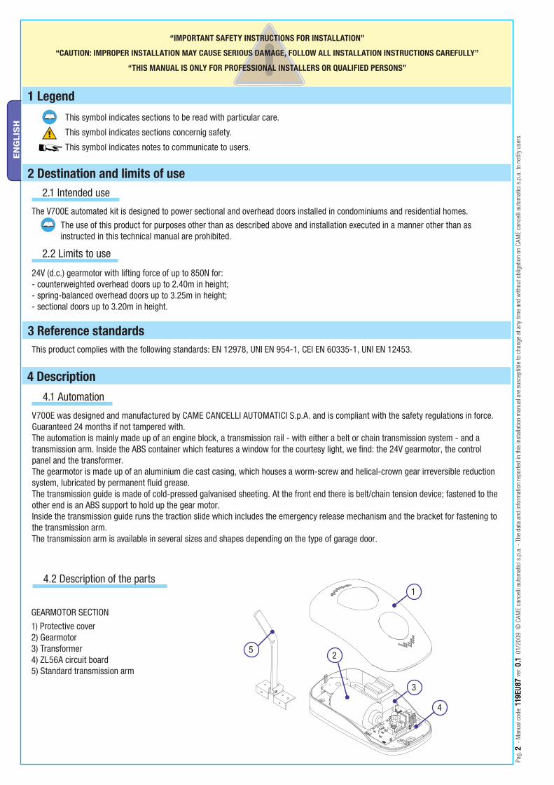
V700E was designed and manufactured by CAME CANCELLI AUTOMATICI S.p.A. and is compliant with the safety regulations in force. Guaranteed 24 months if not tampered with.The automation is mainly made up of an engine block, a transmission rail - with either a belt or chain transmission system - and a transmission arm. Inside the ABS container which features a window for the courtesy light, we fi nd: the 24V gearmotor, the control panel and the transformer. The gearmotor is made up of an aluminium die cast casing, which houses a worm-screw and helical-crown gear irreversible reduction system, lubricated by permanent fl uid grease. The transmission guide is made of cold-pressed galvanised sheeting. At the front end there is belt/chain tension device; fastened to the other end is an ABS support to hold up the gear motor.Inside the transmission guide runs the traction slide which includes the emergency release mechanism and the bracket for fastening to the transmission arm. The transmission arm is available in several sizes and shapes depending on the type of garage door.
4.2 Description of the parts
GEARMOTOR SECTION
1) Protective cover 2) Gearmotor3) Transformer4) ZL56A circuit board5) Standard transmission arm
12
21
Pag.
33 -
Man
ual c
ode :
119
EU87
119E
U87
ver
. 0.10.1
01 /
2009
© C
AME
canc
elli
auto
mat
ici s
.p.a
. - T
he d
ata
and
info
rmat
ion
repo
rted
in th
is in
stal
latio
n m
anua
l are
sus
cept
ible
to c
hang
e at
any
tim
e an
d w
ithou
t obl
igat
ion
on C
AME
canc
elli
auto
mat
ici s
.p.a
. to
notif
y us
ers.
EN
GLIS
HImportant! Check that the safety equipment and accessories are CAME originals; this is a guarantee that also makes the system easy to set up and upkeep.
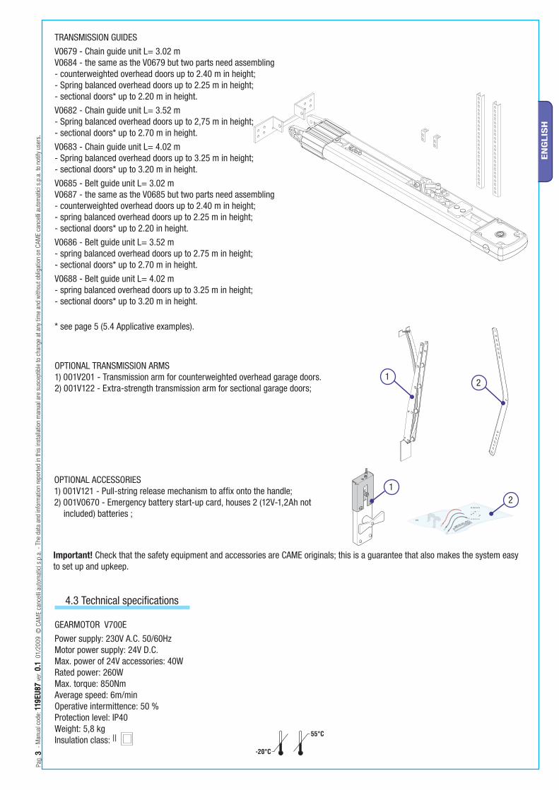
TRANSMISSION GUIDES
V0679 - Chain guide unit L= 3.02 mV0684 - the same as the V0679 but two parts need assembling- counterweighted overhead doors up to 2.40 m in height;- Spring balanced overhead doors up to 2.25 m in height;- sectional doors* up to 2.20 m in height.
V0682 - Chain guide unit L= 3.52 m- Spring balanced overhead doors up to 2,75 m in height;- sectional doors* up to 2.70 m in height.
V0683 - Chain guide unit L= 4.02 m- Spring balanced overhead doors up to 3.25 m in height;- sectional doors* up to 3.20 m in height.
V0685 - Belt guide unit L= 3.02 mV0687 - the same as the V0685 but two parts need assembling- counterweighted overhead doors up to 2.40 m in height;- spring balanced overhead doors up to 2.25 m in height;- sectional doors* up to 2.20 in height.
V0686 - Belt guide unit L= 3.52 m- spring balanced overhead doors up to 2.75 m in height;- sectional doors* up to 2.70 m in height.
V0688 - Belt guide unit L= 4.02 m- spring balanced overhead doors up to 3.25 m in height;- sectional doors* up to 3.20 m in height.
* see page 5 (5.4 Applicative examples).
4.3 Technical specifications
GEARMOTOR V700E
Power supply: 230V A.C. 50/60HzMotor power supply: 24V D.C.Max. power of 24V accessories: 40WRated power: 260WMax. torque: 850NmAverage speed: 6m/minOperative intermittence: 50 %Protection level: IP40Weight: 5,8 kgInsulation class: ||
OPTIONAL TRANSMISSION ARMS1) 001V201 - Transmission arm for counterweighted overhead garage doors.2) 001V122 - Extra-strength transmission arm for sectional garage doors;
OPTIONAL ACCESSORIES1) 001V121 - Pull-string release mechanism to affix onto the handle;2) 001V0670 - Emergency battery start-up card, houses 2 (12V-1,2Ah not
included) batteries ;
Pag.
44 -
Man
ual c
ode:
119
EU87
119E
U87
ver
. 0.10.1
01/
2009
© C
AME
canc
elli
auto
mat
ici s
.p.a
. - T
he d
ata
and
info
rmat
ion
repo
rted
in th
is in
stal
latio
n m
anua
l are
sus
cept
ible
to c
hang
e at
any
tim
e an
d w
ithou
t obl
igat
ion
on C
AME
canc
elli
auto
mat
ici s
.p.a
. to
notif
y us
ers.
EN
GLIS
H
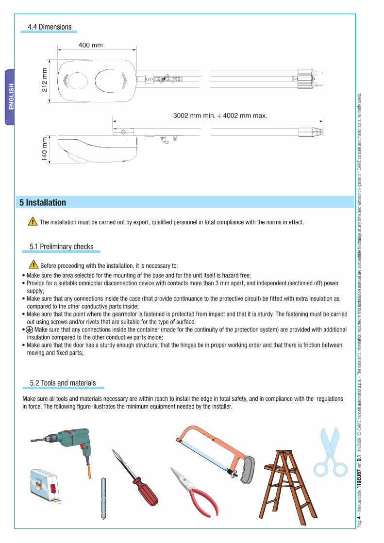
5 Installation
Make sure all tools and materials necessary are within reach to install the edge in total safety, and in compliance with the regulations in force. The following figure illustrates the minimum equipment needed by the installer.
Before proceeding with the installation, it is necessary to:
• Make sure the area selected for the mounting of the base and for the unit itself is hazard free;• Provide for a suitable omnipolar disconnection device with contacts more than 3 mm apart, and independent (sectioned off) power
supply;• Make sure that any connections inside the case (that provide continuance to the protective circuit) be fitted with extra insulation as
compared to the other conductive parts inside;• Make sure that the point where the gearmotor is fastened is protected from impact and that it is sturdy. The fastening must be carried
out using screws and/or rivets that are suitable for the type of surface;• Make sure that any connections inside the container (made for the continuity of the protection system) are provided with additional
insulation compared to the other conductive parts inside;• Make sure that the door has a sturdy enough structure, that the hinges be in proper working order and that there is friction between
moving and fixed parts;
The installation must be carried out by export, qualified personnel in total compliance with the norms in effect.
5.1 Preliminary checks
5.2 Tools and materials
4.4 Dimensions
9
1
6 10
9
3
45
78
2
11
H -
100
mm
H
Pag.
55 -
Man
ual c
ode :
119
EU87
119E
U87
ver
. 0.10.1
01 /
2009
© C
AME
canc
elli
auto
mat
ici s
.p.a
. - T
he d
ata
and
info
rmat
ion
repo
rted
in th
is in
stal
latio
n m
anua
l are
sus
cept
ible
to c
hang
e at
any
tim
e an
d w
ithou
t obl
igat
ion
on C
AME
canc
elli
auto
mat
ici s
.p.a
. to
notif
y us
ers.
EN
GLIS
H
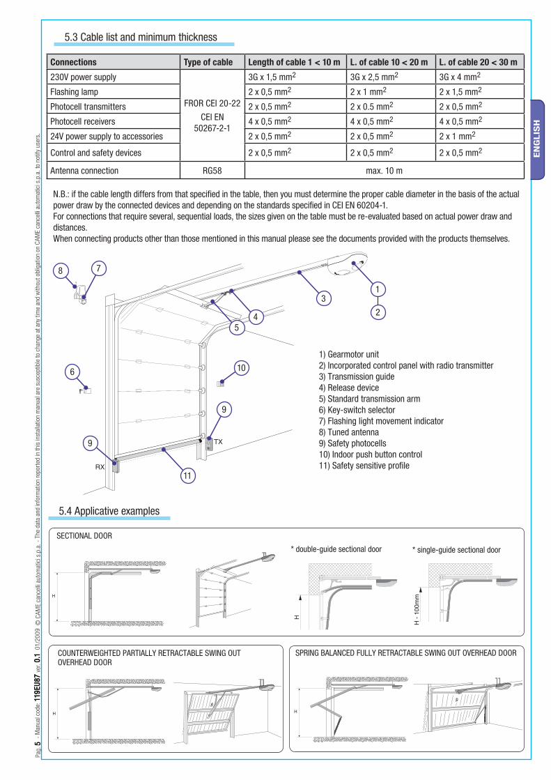
N.B.: if the cable length differs from that specified in the table, then you must determine the proper cable diameter in the basis of the actual power draw by the connected devices and depending on the standards specified in CEI EN 60204-1.For connections that require several, sequential loads, the sizes given on the table must be re-evaluated based on actual power draw and distances.When connecting products other than those mentioned in this manual please see the documents provided with the products themselves.
5.3 Cable list and minimum thickness
Connections Type of cable Length of cable 1 < 10 m L. of cable 10 < 20 m L. of cable 20 < 30 m
230V power supply
FROR CEI 20-22
CEI EN 50267-2-1
3G x 1,5 mm2 3G x 2,5 mm2 3G x 4 mm2
Flashing lamp 2 x 0,5 mm2 2 x 1 mm2 2 x 1,5 mm2
Photocell transmitters 2 x 0,5 mm2 2 x 0.5 mm2 2 x 0,5 mm2
Photocell receivers 4 x 0,5 mm2 4 x 0,5 mm2 4 x 0,5 mm2
24V power supply to accessories 2 x 0,5 mm2 2 x 0,5 mm2 2 x 1 mm2
Control and safety devices 2 x 0,5 mm2 2 x 0,5 mm2 2 x 0,5 mm2
Antenna connection RG58 max. 10 m
1) Gearmotor unit 2) Incorporated control panel with radio transmitter3) Transmission guide4) Release device5) Standard transmission arm6) Key-switch selector7) Flashing light movement indicator 8) Tuned antenna9) Safety photocells10) Indoor push button control11) Safety sensitive profi le
5.4 Applicative examples
* single-guide sectional door * double-guide sectional door
COUNTERWEIGHTED PARTIALLY RETRACTABLE SWING OUT OVERHEAD DOOR
SPRING BALANCED FULLY RETRACTABLE SWING OUT OVERHEAD DOOR
SECTIONAL DOOR
M6 x 20M6
V122
V201
Pag.
66 -
Man
ual c
ode:
119
EU87
119E
U87
ver
. 0.10.1
01/
2009
© C
AME
canc
elli
auto
mat
ici s
.p.a
. - T
he d
ata
and
info
rmat
ion
repo
rted
in th
is in
stal
latio
n m
anua
l are
sus
cept
ible
to c
hang
e at
any
tim
e an
d w
ithou
t obl
igat
ion
on C
AME
canc
elli
auto
mat
ici s
.p.a
. to
notif
y us
ers.
EN
GLIS
H
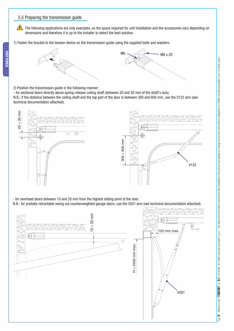
The following applications are only examples, as the space required for unit installation and the accessories vary depending on dimensions and therefore it is up to the installer to select the best solution.
2) Position the transmission guide in the following manner:- for sectional doors directly above spring-release coiling shaft (between 20 and 30 mm of the shaft’s axis).N.B.: if the distance between the coiling shaft and the top part of the door is between 300 and 600 mm, use the V122 arm (see technical documentation attached);
1) Fasten the bracket to the tension device on the transmission guide using the supplied bolts and washers.
- for overhead doors between 10 and 20 mm from the highest sliding point of the door.N.B.: for pratially-retractable swing out counterweighted garage doors, use the V201 arm (see technical documentation attached).
5.5 Preparing the transmission guide
M6 x 14
M6
Pag.
77 -
Man
ual c
ode :
119
EU87
119E
U87
ver
. 0.10.1
01 /
2009
© C
AME
canc
elli
auto
mat
ici s
.p.a
. - T
he d
ata
and
info
rmat
ion
repo
rted
in th
is in
stal
latio
n m
anua
l are
sus
cept
ible
to c
hang
e at
any
tim
e an
d w
ithou
t obl
igat
ion
on C
AME
canc
elli
auto
mat
ici s
.p.a
. to
notif
y us
ers.
EN
GLIS
H
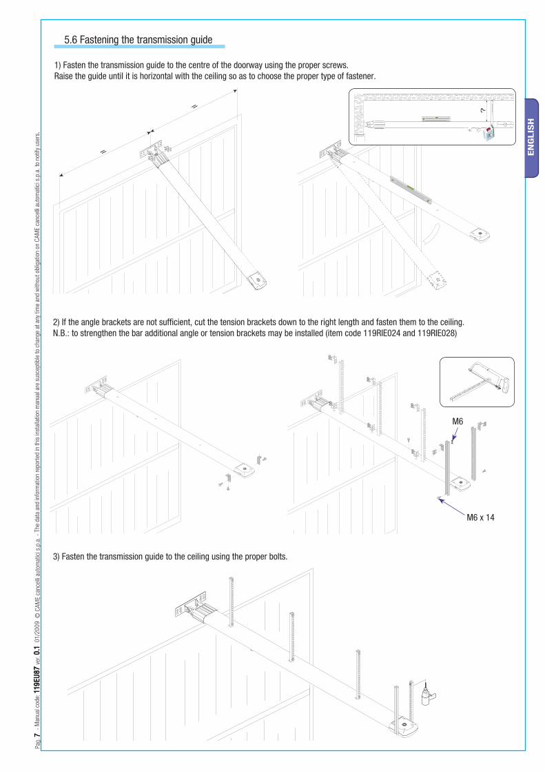
1) Fasten the transmission guide to the centre of the doorway using the proper screws. Raise the guide until it is horizontal with the ceiling so as to choose the proper type of fastener.
2) If the angle brackets are not suffi cient, cut the tension brackets down to the right length and fasten them to the ceiling.N.B.: to strengthen the bar additional angle or tension brackets may be installed (item code 119RIE024 and 119RIE028)
3) Fasten the transmission guide to the ceiling using the proper bolts.
5.6 Fastening the transmission guide
UNI 5739 M6 x 20
Pag.
88 -
Man
ual c
ode:
119
EU87
119E
U87
ver
. 0.10.1
01/
2009
© C
AME
canc
elli
auto
mat
ici s
.p.a
. - T
he d
ata
and
info
rmat
ion
repo
rted
in th
is in
stal
latio
n m
anua
l are
sus
cept
ible
to c
hang
e at
any
tim
e an
d w
ithou
t obl
igat
ion
on C
AME
canc
elli
auto
mat
ici s
.p.a
. to
notif
y us
ers.
EN
GLIS
H
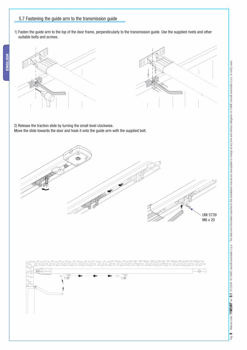
1) Fasten the guide arm to the top of the door frame, perpendicularly to the transmission guide. Use the supplied rivets and other suitable bolts and screws.
5.7 Fastening the guide arm to the transmission guide
2) Release the traction slide by turning the small level clockwise. Move the slide towards the door and hook it onto the guide arm with the supplied bolt.
UNI 6954 ø 3.9 x 13
UNI 6955 ø 6.3 x 45
Pag.
99 -
Man
ual c
ode :
119
EU87
119E
U87
ver
. 0.10.1
01 /
2009
© C
AME
canc
elli
auto
mat
ici s
.p.a
. - T
he d
ata
and
info
rmat
ion
repo
rted
in th
is in
stal
latio
n m
anua
l are
sus
cept
ible
to c
hang
e at
any
tim
e an
d w
ithou
t obl
igat
ion
on C
AME
canc
elli
auto
mat
ici s
.p.a
. to
notif
y us
ers.
EN
GLIS
H
5.8 Fastening the gearmotor to the transmission guide
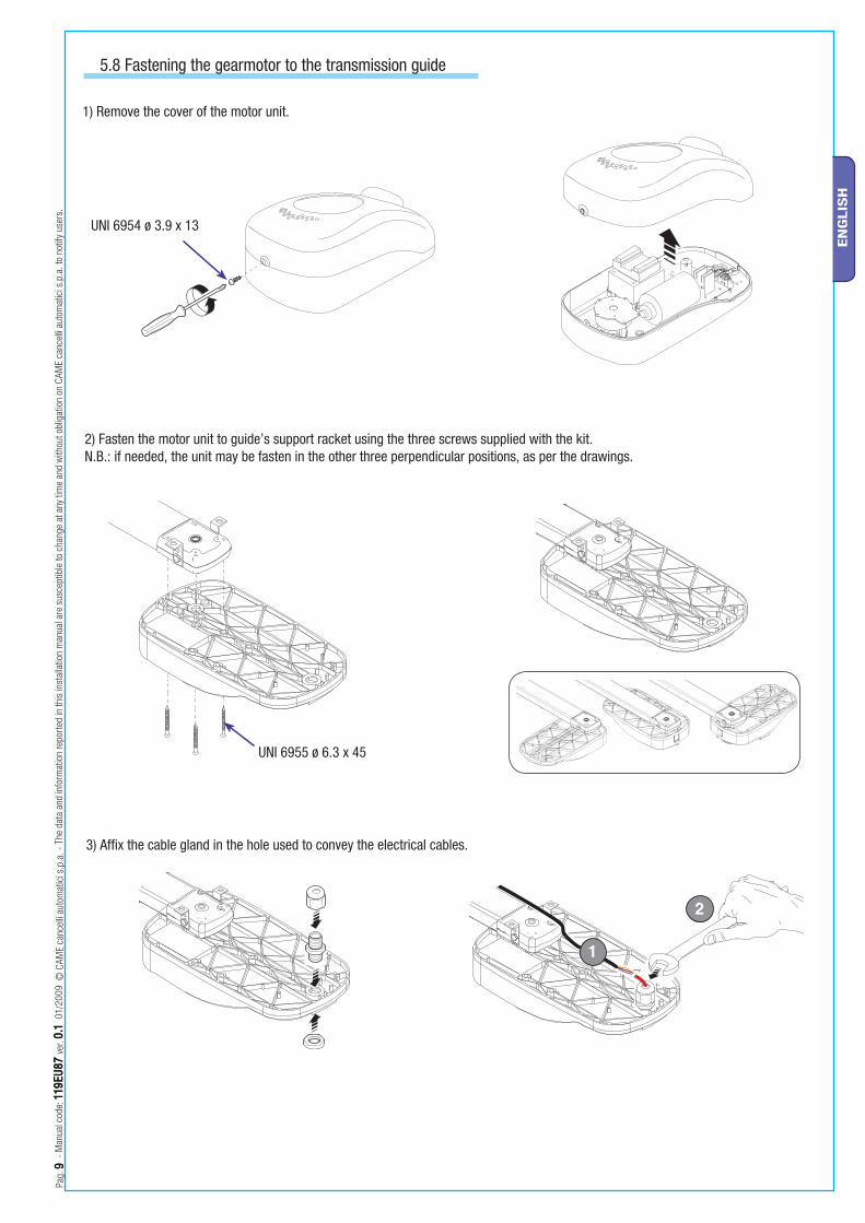
1) Remove the cover of the motor unit.
2) Fasten the motor unit to guide’s support racket using the three screws supplied with the kit.N.B.: if needed, the unit may be fasten in the other three perpendicular positions, as per the drawings.
3) Affi x the cable gland in the hole used to convey the electrical cables.
Pag.
1010
- M
anua
l cod
e: 1
19EU
8711
9EU
87 v
er. 0
.10.1
01/
2009
© C
AME
canc
elli
auto
mat
ici s
.p.a
. - T
he d
ata
and
info
rmat
ion
repo
rted
in th
is in
stal
latio
n m
anua
l are
sus
cept
ible
to c
hang
e at
any
tim
e an
d w
ithou
t obl
igat
ion
on C
AME
canc
elli
auto
mat
ici s
.p.a
. to
notif
y us
ers.
EN
GLIS
H
6.1 General description
6 Electronic control panel
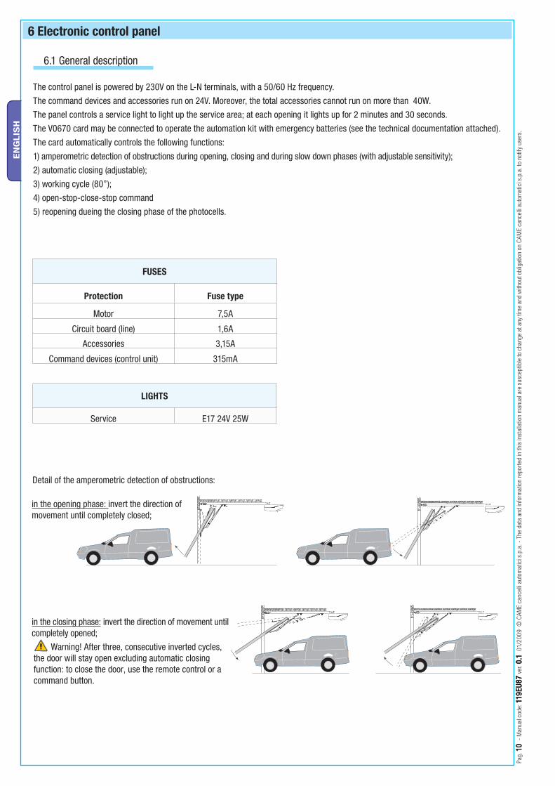
The control panel is powered by 230V on the L-N terminals, with a 50/60 Hz frequency.
The command devices and accessories run on 24V. Moreover, the total accessories cannot run on more than 40W.
The panel controls a service light to light up the service area; at each opening it lights up for 2 minutes and 30 seconds.
The V0670 card may be connected to operate the automation kit with emergency batteries (see the technical documentation attached).
The card automatically controls the following functions:
1) amperometric detection of obstructions during opening, closing and during slow down phases (with adjustable sensitivity);
2) automatic closing (adjustable);
3) working cycle (80”);
4) open-stop-close-stop command
5) reopening dueing the closing phase of the photocells.
in the closing phase: invert the direction of movement until completely opened;
Warning! After three, consecutive inverted cycles, the door will stay open excluding automatic closing function: to close the door, use the remote control or a command button.
in the opening phase: invert the direction of movement until completely closed;
FUSES
Protection Fuse type
Motor 7,5A
Circuit board (line) 1,6A
Accessories 3,15A
Command devices (control unit) 315mA
LIGHTS
Service E17 24V 25W
Detail of the amperometric detection of obstructions:
+
2
3
4
19
5 7 8
9
1011
1 6
18 12 13 14 15
16
17
24 20
22
2521
23
-
Pag.
1111
- M
anua
l cod
e : 1
19EU
8711
9EU
87 v
er. 0
.10.1
01 /
2009
© C
AME
canc
elli
auto
mat
ici s
.p.a
. - T
he d
ata
and
info
rmat
ion
repo
rted
in th
is in
stal
latio
n m
anua
l are
sus
cept
ible
to c
hang
e at
any
tim
e an
d w
ithou
t obl
igat
ion
on C
AME
canc
elli
auto
mat
ici s
.p.a
. to
notif
y us
ers.
EN
GLIS
H
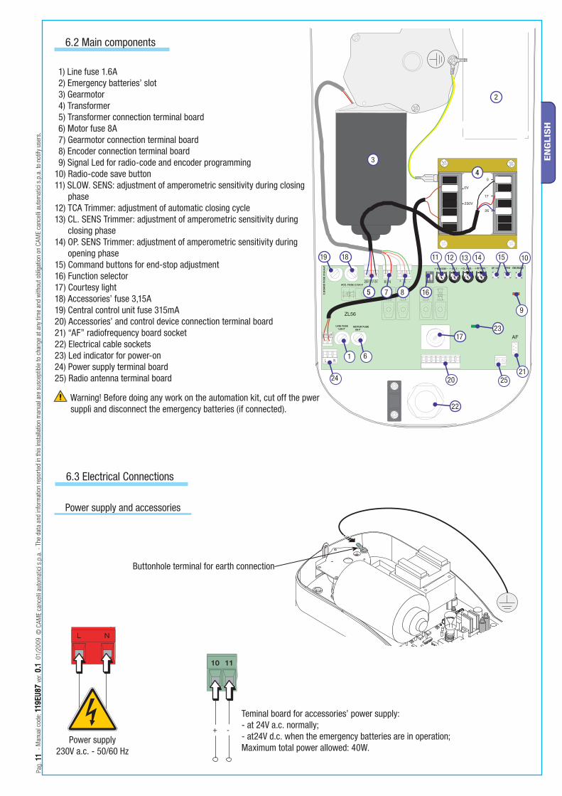
6.2 Main components
1) Line fuse 1.6A2) Emergency batteries’ slot3) Gearmotor4) Transformer5) Transformer connection terminal board6) Motor fuse 8A7) Gearmotor connection terminal board8) Encoder connection terminal board9) Signal Led for radio-code and encoder programming
10) Radio-code save button11) SLOW. SENS: adjustment of amperometric sensitivity during closing
phase12) TCA Trimmer: adjustment of automatic closing cycle13) CL. SENS Trimmer: adjustment of amperometric sensitivity during
closing phase14) OP. SENS Trimmer: adjustment of amperometric sensitivity during
opening phase15) Command buttons for end-stop adjustment16) Function selector17) Courtesy light18) Accessories’ fuse 3,15A19) Central control unit fuse 315mA20) Accessories’ and control device connection terminal board21) “AF” radiofrequency board socket22) Electrical cable sockets23) Led indicator for power-on24) Power supply terminal board25) Radio antenna terminal board
6.3 Electrical Connections
Power supply and accessories
Teminal board for accessories’ power supply: - at 24V a.c. normally;- at24V d.c. when the emergency batteries are in operation;Maximum total power allowed: 40W.
Buttonhole terminal for earth connection
Power supply 230V a.c. - 50/60 Hz
Warning! Before doing any work on the automation kit, cut off the pwer supplì and disconnect the emergency batteries (if connected).
RX TX
Pag.
1212
- M
anua
l cod
e: 1
19EU
8711
9EU
87 v
er. 0
.10.1
01/
2009
© C
AME
canc
elli
auto
mat
ici s
.p.a
. - T
he d
ata
and
info
rmat
ion
repo
rted
in th
is in
stal
latio
n m
anua
l are
sus
cept
ible
to c
hang
e at
any
tim
e an
d w
ithou
t obl
igat
ion
on C
AME
canc
elli
auto
mat
ici s
.p.a
. to
notif
y us
ers.
EN
GLIS
H
RE
D
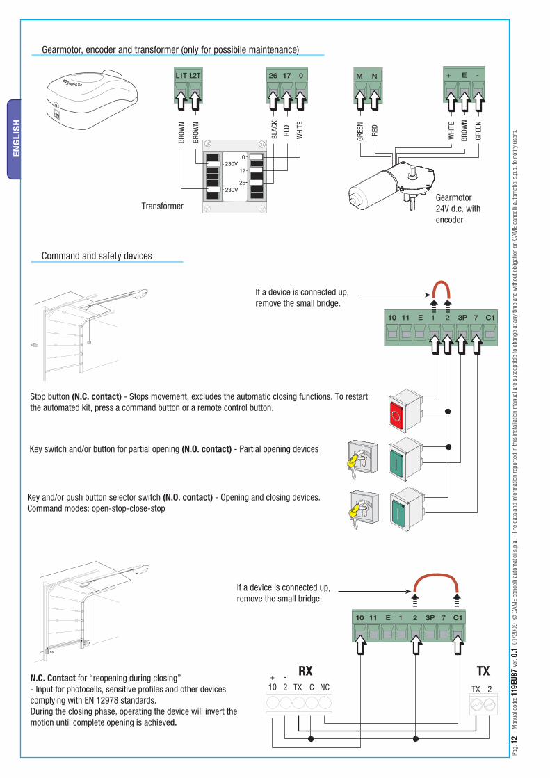
Gearmotor, encoder and transformer (only for possibile maintenance)
RE
D
BLAC
K
WHI
TE
BROW
N
BROW
N
GREE
N
GRE
EN
BRO
WN
WHI
TE
Gearmotor 24V d.c. with encoder
Transformer
Command and safety devices
Stop button (N.C. contact) - Stops movement, excludes the automatic closing functions. To restart the automated kit, press a command button or a remote control button.
Key and/or push button selector switch (N.O. contact) - Opening and closing devices. Command modes: open-stop-close-stop
N.C. Contact for “reopening during closing”- Input for photocells, sensitive profi les and other devices complying with EN 12978 standards.During the closing phase, operating the device will invert the motion until complete opening is achieved.
If a device is connected up, remove the small bridge.
Key switch and/or button for partial opening (N.O. contact) - Partial opening devices
If a device is connected up, remove the small bridge.
ON
OFF
Pag.
1313
- M
anua
l cod
e : 1
19EU
8711
9EU
87 v
er. 0
.10.1
01 /
2009
© C
AME
canc
elli
auto
mat
ici s
.p.a
. - T
he d
ata
and
info
rmat
ion
repo
rted
in th
is in
stal
latio
n m
anua
l are
sus
cept
ible
to c
hang
e at
any
tim
e an
d w
ithou
t obl
igat
ion
on C
AME
canc
elli
auto
mat
ici s
.p.a
. to
notif
y us
ers.
EN
GLIS
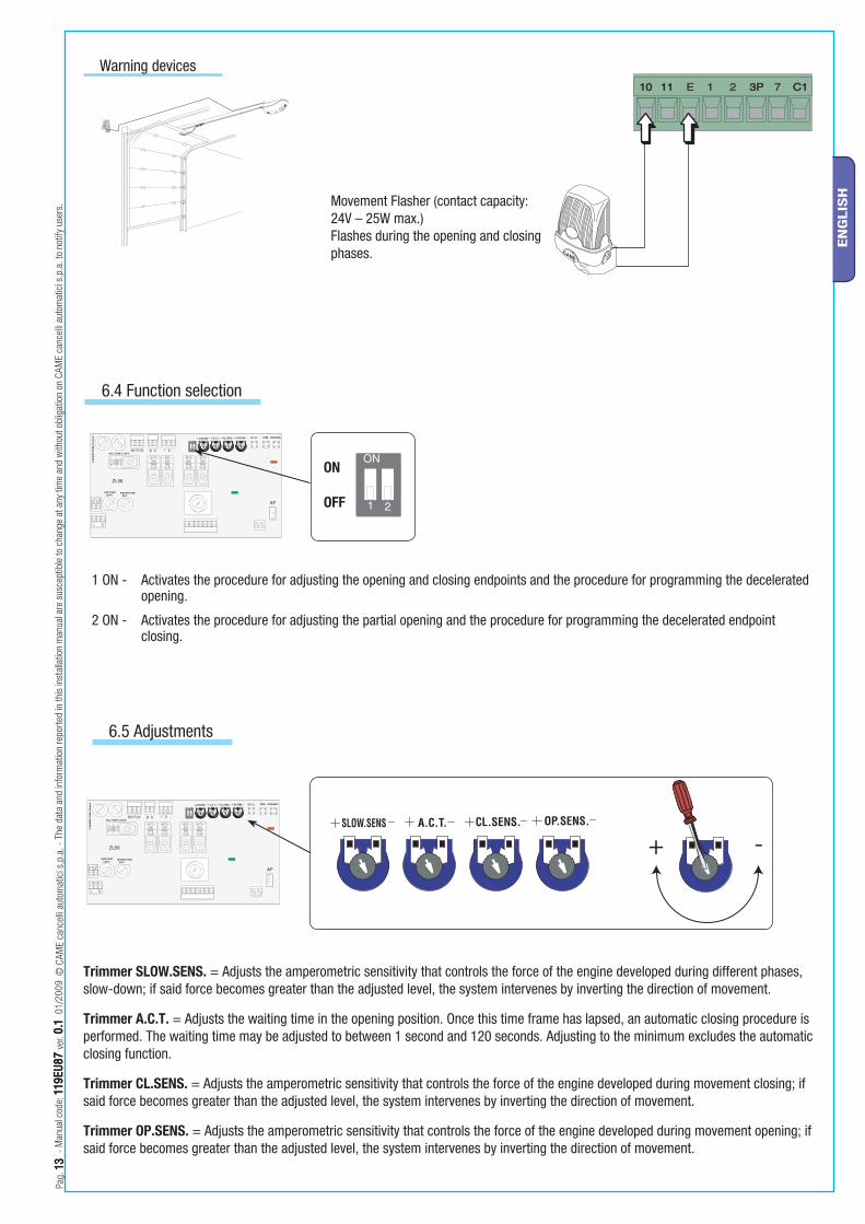
HMovement Flasher (contact capacity: 24V – 25W max.) Flashes during the opening and closing phases.
Warning devices
6.5 Adjustments
6.4 Function selection
Trimmer SLOW.SENS. = Adjusts the amperometric sensitivity that controls the force of the engine developed during different phases, slow-down; if said force becomes greater than the adjusted level, the system intervenes by inverting the direction of movement.
Trimmer A.C.T. = Adjusts the waiting time in the opening position. Once this time frame has lapsed, an automatic closing procedure is performed. The waiting time may be adjusted to between 1 second and 120 seconds. Adjusting to the minimum excludes the automatic closing function.
Trimmer CL.SENS. = Adjusts the amperometric sensitivity that controls the force of the engine developed during movement closing; if said force becomes greater than the adjusted level, the system intervenes by inverting the direction of movement.
Trimmer OP.SENS. = Adjusts the amperometric sensitivity that controls the force of the engine developed during movement opening; if said force becomes greater than the adjusted level, the system intervenes by inverting the direction of movement.
1 ON - Activates the procedure for adjusting the opening and closing endpoints and the procedure for programming the decelerated opening.
2 ON - Activates the procedure for adjusting the partial opening and the procedure for programming the decelerated endpoint closing.
Pag.
1414
- M
anua
l cod
e: 1
19EU
8711
9EU
87 v
er. 0
.10.1
01/
2009
© C
AME
canc
elli
auto
mat
ici s
.p.a
. - T
he d
ata
and
info
rmat
ion
repo
rted
in th
is in
stal
latio
n m
anua
l are
sus
cept
ible
to c
hang
e at
any
tim
e an
d w
ithou
t obl
igat
ion
on C
AME
canc
elli
auto
mat
ici s
.p.a
. to
notif
y us
ers.
EN
GLIS
H
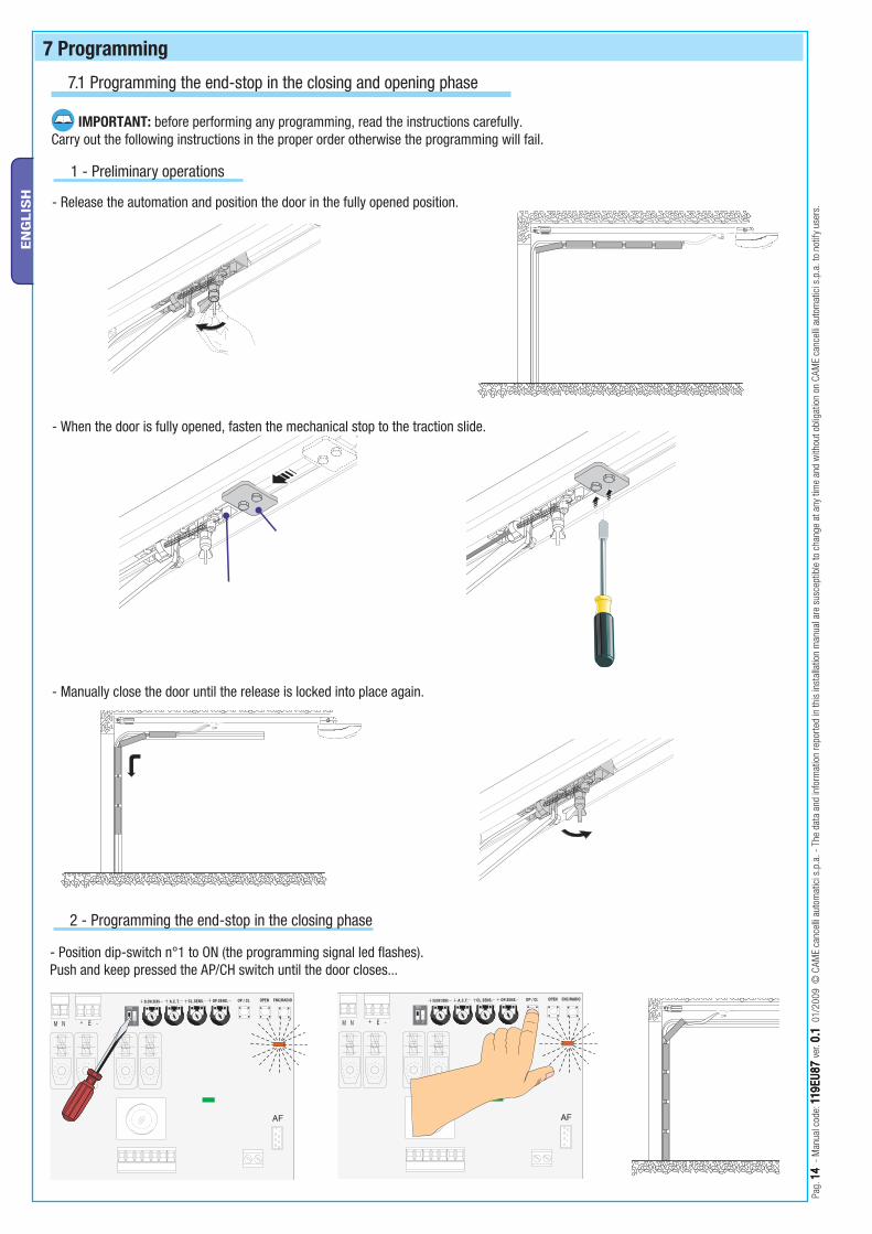
7 Programming
- Release the automation and position the door in the fully opened position.
IMPORTANT: before performing any programming, read the instructions carefully.Carry out the following instructions in the proper order otherwise the programming will fail.
- When the door is fully opened, fasten the mechanical stop to the traction slide.
1 - Preliminary operations
- Position dip-switch n°1 to ON (the programming signal led fl ashes).Push and keep pressed the AP/CH switch until the door closes...
2 - Programming the end-stop in the closing phase
- Manually close the door until the release is locked into place again.
7.1 Programming the end-stop in the closing and opening phase
CL.SENS.
ZL56A
OP.SENS.
MOTOR FUSE 8A-F
21
ON
ACC. FUSE 3,15A-F
LINE FUSE 1,6A-F
OPENOP / CL
AF
26V 17V 0V M N + E -
ENC/RADIOA.C.T.SLOW.SENS
N
CL.SENS.
ZL56A
OP.SENS.
MOTOR FUSE 8A-F
21
ON
ACC. FUSE 3,15A-F
LINE FUSE 1,6A-F
OPENOP / CL
AF
26V 17V 0V M N + E -
ENC/RADIOA.C.T.SLOW.SENS
CL.SENS.
ZL56A
OP.SENS.
MOTOR FUSE 8A-F
21
ON
ACC. FUSE 3,15A-F
E FUSE6A-F
OPENOP / CL
AF
26V 17V 0V M N + E -
ENC/RADIOA.C.T.SLOW.SENS
CL.SENS.
ZL56A
OP.SENS.
MOTOR FUSE 8A-F
21
ON
ACC. FUSE 3,15A-F
NE FUSE1,6A-F
OPENOP / CL
AF
26V 17V 0V M N + E -
ENC/RADIOA.C.T.SLOW.SENS CL.SENS.
ZL56A
OP.SENS.
MOTOR FUSE 8A-F
21
ON
ACC. FUSE 3,15A-F
NE FUSE1,6A-F
OPENOP / CL
AF
26V 17V 0V M N + E -
ENC/RADIOA.C.T.SLOW.SENS
Pag.
1515
- M
anua
l cod
e : 1
19EU
8711
9EU
87 v
er. 0
.10.1
01 /
2009
© C
AME
canc
elli
auto
mat
ici s
.p.a
. - T
he d
ata
and
info
rmat
ion
repo
rted
in th
is in
stal
latio
n m
anua
l are
sus
cept
ible
to c
hang
e at
any
tim
e an
d w
ithou
t obl
igat
ion
on C
AME
canc
elli
auto
mat
ici s
.p.a
. to
notif
y us
ers.
EN
GLIS
H
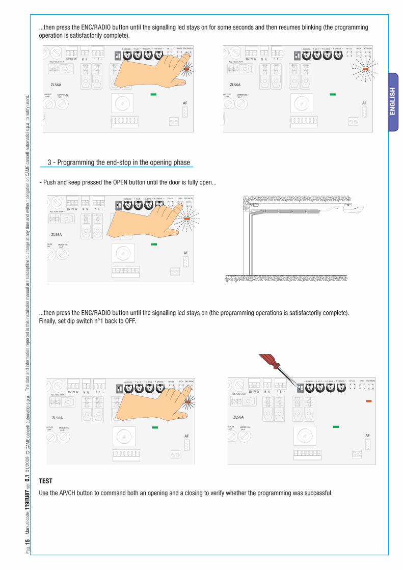
...then press the ENC/RADIO button until the signalling led stays on for some seconds and then resumes blinking (the programming operation is satisfactorily complete).
- Push and keep pressed the OPEN button until the door is fully open...
3 - Programming the end-stop in the opening phase
...then press the ENC/RADIO button until the signalling led stays on (the programming operations is satisfactorily complete).Finally, set dip switch n°1 back to OFF.
TEST
Use the AP/CH button to command both an opening and a closing to verify whether the programming was successful.
CL.SENS.
ZL56A
OP.SENS.
MOTOR FUSE 8A-F
21
ON
ACC. FUSE 3,15A-F
NE FUSE1,6A-F
OPENOP / CL
AF
26V 17V 0V M N + E -
ENC/RADIOA.C.T.SLOW.SENS
Pag.
1616
- M
anua
l cod
e: 1
19EU
8711
9EU
87 v
er. 0
.10.1
01/
2009
© C
AME
canc
elli
auto
mat
ici s
.p.a
. - T
he d
ata
and
info
rmat
ion
repo
rted
in th
is in
stal
latio
n m
anua
l are
sus
cept
ible
to c
hang
e at
any
tim
e an
d w
ithou
t obl
igat
ion
on C
AME
canc
elli
auto
mat
ici s
.p.a
. to
notif
y us
ers.
EN
GLIS
H
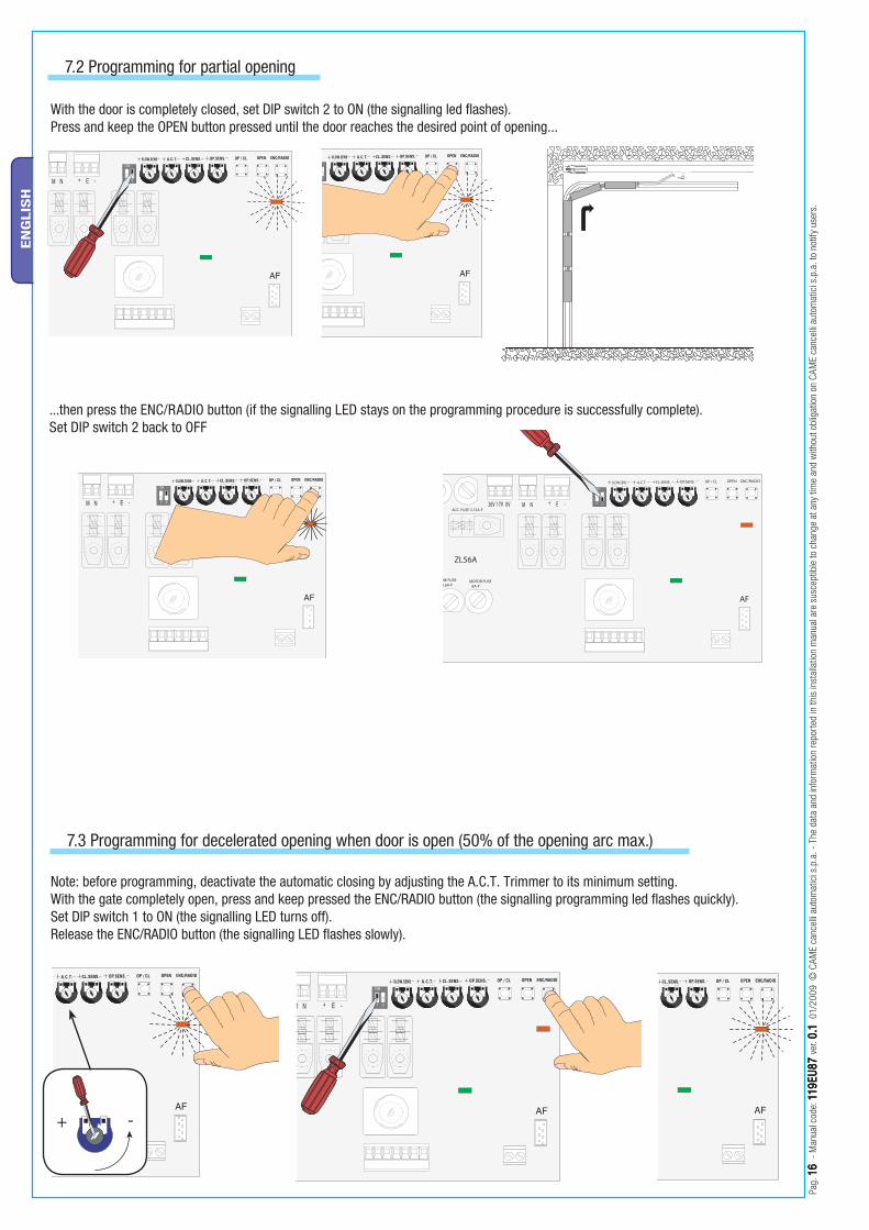
With the door is completely closed, set DIP switch 2 to ON (the signalling led fl ashes).Press and keep the OPEN button pressed until the door reaches the desired point of opening...
7.3 Programming for decelerated opening when door is open (50% of the opening arc max.)
Note: before programming, deactivate the automatic closing by adjusting the A.C.T. Trimmer to its minimum setting.With the gate completely open, press and keep pressed the ENC/RADIO button (the signalling programming led fl ashes quickly).Set DIP switch 1 to ON (the signalling LED turns off).Release the ENC/RADIO button (the signalling LED fl ashes slowly).
...then press the ENC/RADIO button (if the signalling LED stays on the programming procedure is successfully complete).Set DIP switch 2 back to OFF
7.2 Programming for partial opening
Pag.
1717
- M
anua
l cod
e : 1
19EU
8711
9EU
87 v
er. 0
.10.1
01 /
2009
© C
AME
canc
elli
auto
mat
ici s
.p.a
. - T
he d
ata
and
info
rmat
ion
repo
rted
in th
is in
stal
latio
n m
anua
l are
sus
cept
ible
to c
hang
e at
any
tim
e an
d w
ithou
t obl
igat
ion
on C
AME
canc
elli
auto
mat
ici s
.p.a
. to
notif
y us
ers.
EN
GLIS
H
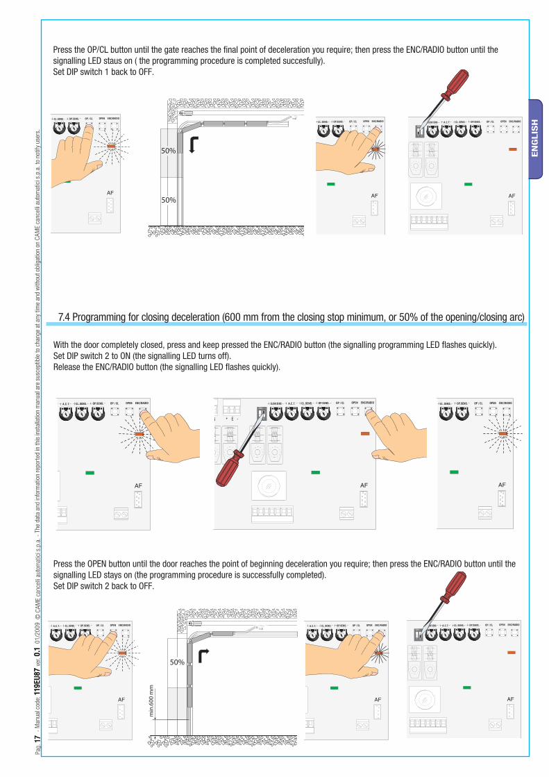
7.4 Programming for closing deceleration (600 mm from the closing stop minimum, or 50% of the opening/closing arc)
With the door completely closed, press and keep pressed the ENC/RADIO button (the signalling programming LED fl ashes quickly).Set DIP switch 2 to ON (the signalling LED turns off).Release the ENC/RADIO button (the signalling LED fl ashes quickly).
Press the OP/CL button until the gate reaches the fi nal point of deceleration you require; then press the ENC/RADIO button until the signalling LED staus on ( the programming procedure is completed succesfully).Set DIP switch 1 back to OFF.
Press the OPEN button until the door reaches the point of beginning deceleration you require; then press the ENC/RADIO button until the signalling LED stays on (the programming procedure is successfully completed).Set DIP switch 2 back to OFF.
CL.SENS.
ZL56A
OP.SENS.
MOTOR FUSE 8A-F
21
ON
ACC. FUSE 3,15A-F
LINE FUSE 1,6A-F
OPENOP / CL
AF
26V 17V 0V M N + E -
ENC/RADIOA.C.T.SLOW.SENS
C.BO
ARD
FU
SE 3
15m
A-F
L1T
L
L2T
N
ATOMO
AT01 • AT02 • AT04
CAME
CAMECAME
CAMECAME
CAMECAME
TOP
TOP-432NA • TOP-434NATOP-432S
TOP
TOP-302A • TOP-304A
TOP
TOP-432A • TOP-434A
TAM
T432 • T434 • T438 TAM-432SA
CAMECAME
CAME
TOUCH
TCH 4024 • TCH 4048
TWIN
TWIN2 • TWIN4
CAME
CAME
CAME
CAME
CAME
CAME
TFM
T132 • T134 • T138T152 • T154 • T158
AF43S
AF30 AF40AF150
AF43TWTWIN
TWIN2 • TWIN4
Pag.
1818
- M
anua
l cod
e: 1
19EU
8711
9EU
87 v
er. 0
.10.1
01/
2009
© C
AME
canc
elli
auto
mat
ici s
.p.a
. - T
he d
ata
and
info
rmat
ion
repo
rted
in th
is in
stal
latio
n m
anua
l are
sus
cept
ible
to c
hang
e at
any
tim
e an
d w
ithou
t obl
igat
ion
on C
AME
canc
elli
auto
mat
ici s
.p.a
. to
notif
y us
ers.
EN
GLIS
H
Radiofrequency card
Electrical board
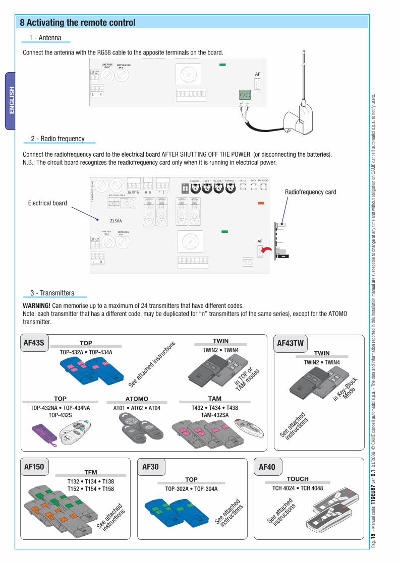
8 Activating the remote control
Connect the radiofrequency card to the electrical board AFTER SHUTTING OFF THE POWER (or disconnecting the batteries). N.B.: The circuit board recognizes the readiofrequency card only when it is running in electrical power.
Connect the antenna with the RG58 cable to the apposite terminals on the board.
1 - Antenna
2 - Radio frequency
3 - Transmitters
WARNING! Can memorise up to a maximum of 24 transmitters that have different codes.Note: each transmitter that has a different code, may be duplicated for “n” transmitters (of the same series), except for the ATOMO transmitter.
See a
ttach
ed
instru
ction
s
See a
ttach
ed
instru
ction
s
See a
ttach
ed
instru
ction
s
See a
ttach
ed
instru
ction
s
in Ke
y-Bloc
k
Mode
in TO
P or
TAM m
odes
See a
ttach
ed in
struc
tions
T2
T1
Pag.
1919
- M
anua
l cod
e : 1
19EU
8711
9EU
87 v
er. 0
.10.1
01 /
2009
© C
AME
canc
elli
auto
mat
ici s
.p.a
. - T
he d
ata
and
info
rmat
ion
repo
rted
in th
is in
stal
latio
n m
anua
l are
sus
cept
ible
to c
hang
e at
any
tim
e an
d w
ithou
t obl
igat
ion
on C
AME
canc
elli
auto
mat
ici s
.p.a
. to
notif
y us
ers.
EN
GLIS
H
Flashing LED
ENC/RADIO
Lit LED
AF Card
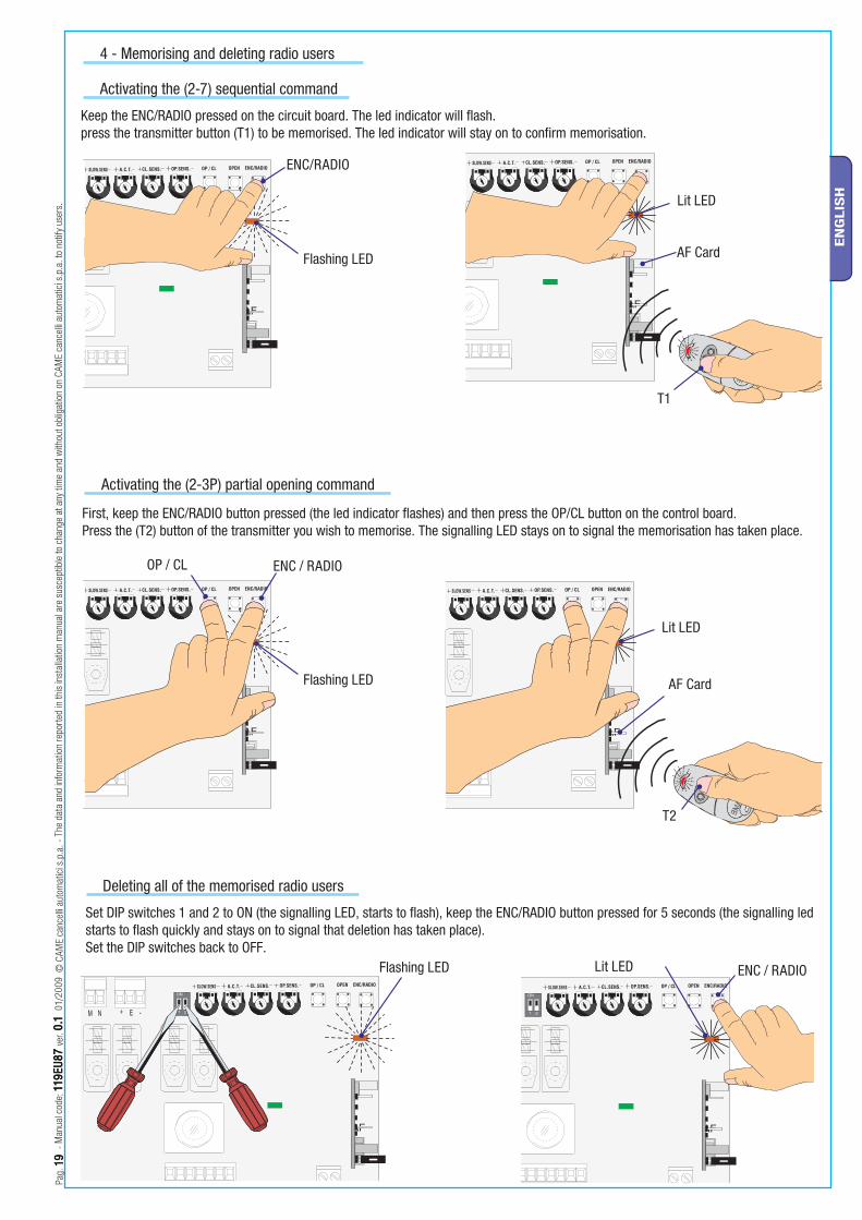
Keep the ENC/RADIO pressed on the circuit board. The led indicator will fl ash.press the transmitter button (T1) to be memorised. The led indicator will stay on to confi rm memorisation.
Flashing LED
ENC / RADIO
Lit LED
AF Card
OP / CL
First, keep the ENC/RADIO button pressed (the led indicator fl ashes) and then press the OP/CL button on the control board.Press the (T2) button of the transmitter you wish to memorise. The signalling LED stays on to signal the memorisation has taken place.
Set DIP switches 1 and 2 to ON (the signalling LED, starts to fl ash), keep the ENC/RADIO button pressed for 5 seconds (the signalling led starts to fl ash quickly and stays on to signal that deletion has taken place).Set the DIP switches back to OFF.
ENC / RADIOFlashing LED Lit LED
Activating the (2-3P) partial opening command
Deleting all of the memorised radio users
Activating the (2-7) sequential command
4 - Memorising and deleting radio users
Pag.
2020
- M
anua
l cod
e: 1
19EU
8711
9EU
87 v
er. 0
.10.1
01/
2009
© C
AME
canc
elli
auto
mat
ici s
.p.a
. - T
he d
ata
and
info
rmat
ion
repo
rted
in th
is in
stal
latio
n m
anua
l are
sus
cept
ible
to c
hang
e at
any
tim
e an
d w
ithou
t obl
igat
ion
on C
AME
canc
elli
auto
mat
ici s
.p.a
. to
notif
y us
ers.
EN
GLIS
H
10 Maintenance
10.1 Periodic maintenance
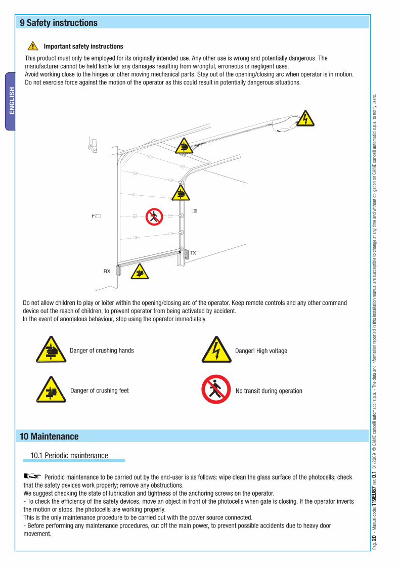
Periodic maintenance to be carried out by the end-user is as follows: wipe clean the glass surface of the photocells; check that the safety devices work properly; remove any obstructions.We suggest checking the state of lubrication and tightness of the anchoring screws on the operator.- To check the efficiency of the safety devices, move an object in front of the photocells when gate is closing. If the operator inverts the motion or stops, the photocells are working properly.This is the only maintenance procedure to be carried out with the power source connected.- Before performing any maintenance procedures, cut off the main power, to prevent possible accidents due to heavy door movement.
9 Safety instructions
This product must only be employed for its originally intended use. Any other use is wrong and potentially dangerous. The manufacturer cannot be held liable for any damages resulting from wrongful, erroneous or negligent uses.Avoid working close to the hinges or other moving mechanical parts. Stay out of the opening/closing arc when operator is in motion.Do not exercise force against the motion of the operator as this could result in potentially dangerous situations.
Do not allow children to play or loiter within the opening/closing arc of the operator. Keep remote controls and any other command device out the reach of children, to prevent operator from being activated by accident.In the event of anomalous behaviour, stop using the operator immediately.
Important safety instructions
Danger of crushing hands
Danger of crushing feet
Danger! High voltage
No transit during operation
Pag.
2121
- M
anua
l cod
e : 1
19EU
8711
9EU
87 v
er. 0
.10.1
01 /
2009
© C
AME
canc
elli
auto
mat
ici s
.p.a
. - T
he d
ata
and
info
rmat
ion
repo
rted
in th
is in
stal
latio
n m
anua
l are
sus
cept
ible
to c
hang
e at
any
tim
e an
d w
ithou
t obl
igat
ion
on C
AME
canc
elli
auto
mat
ici s
.p.a
. to
notif
y us
ers.
EN
GLIS
H
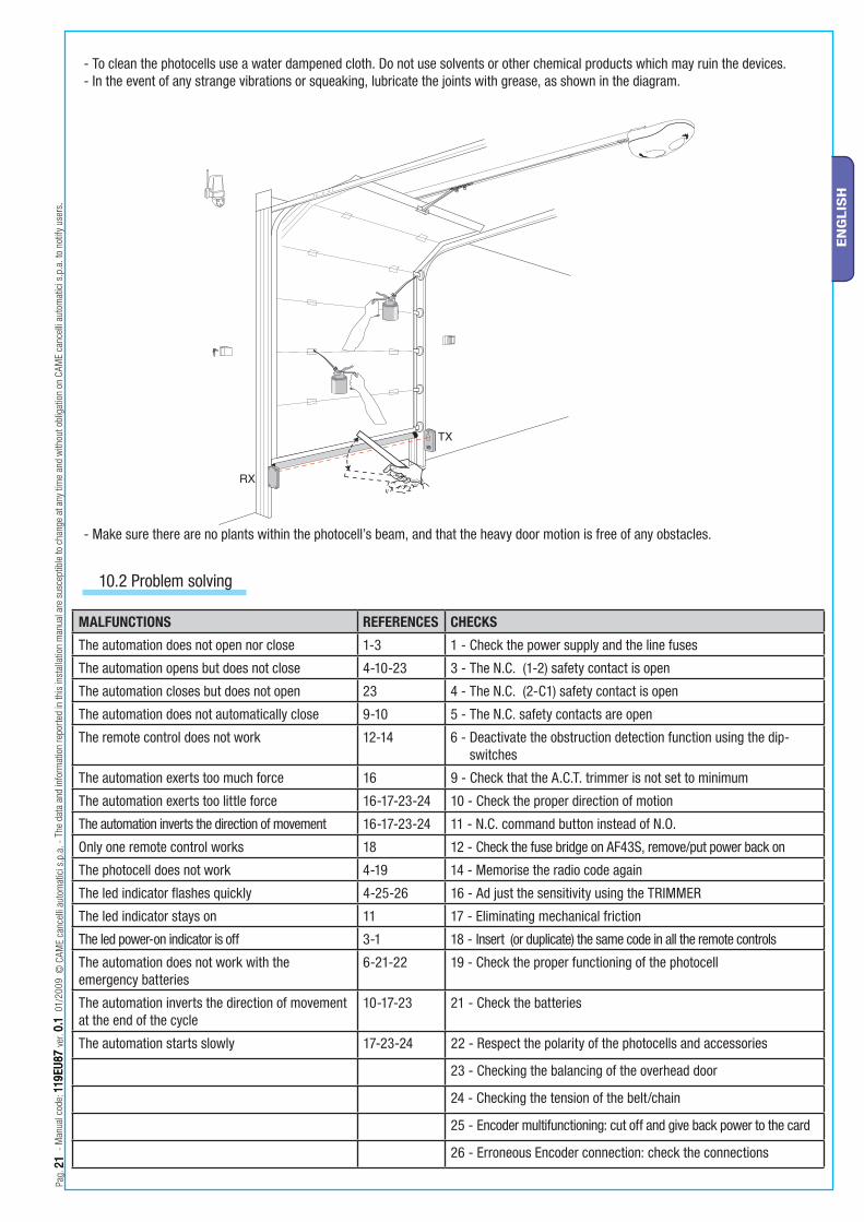
- To clean the photocells use a water dampened cloth. Do not use solvents or other chemical products which may ruin the devices.- In the event of any strange vibrations or squeaking, lubricate the joints with grease, as shown in the diagram.
- Make sure there are no plants within the photocell’s beam, and that the heavy door motion is free of any obstacles.
10.2 Problem solving
MALFUNCTIONS REFERENCES CHECKS
The automation does not open nor close 1-3 1 - Check the power supply and the line fuses
The automation opens but does not close 4-10-23 3 - The N.C. (1-2) safety contact is open
The automation closes but does not open 23 4 - The N.C. (2-C1) safety contact is open
The automation does not automatically close 9-10 5 - The N.C. safety contacts are open
The remote control does not work 12-14 6 - Deactivate the obstruction detection function using the dip-switches
The automation exerts too much force 16 9 - Check that the A.C.T. trimmer is not set to minimum
The automation exerts too little force 16-17-23-24 10 - Check the proper direction of motion
The automation inverts the direction of movement 16-17-23-24 11 - N.C. command button instead of N.O.
Only one remote control works 18 12 - Check the fuse bridge on AF43S, remove/put power back on
The photocell does not work 4-19 14 - Memorise the radio code again
The led indicator flashes quickly 4-25-26 16 - Ad just the sensitivity using the TRIMMER
The led indicator stays on 11 17 - Eliminating mechanical friction
The led power-on indicator is off 3-1 18 - Insert (or duplicate) the same code in all the remote controls
The automation does not work with the emergency batteries
6-21-22 19 - Check the proper functioning of the photocell
The automation inverts the direction of movement at the end of the cycle
10-17-23 21 - Check the batteries
The automation starts slowly 17-23-24 22 - Respect the polarity of the photocells and accessories
23 - Checking the balancing of the overhead door
24 - Checking the tension of the belt/chain
25 - Encoder multifunctioning: cut off and give back power to the card
26 - Erroneous Encoder connection: check the connections
Pag.
2222
- M
anua
l cod
e: 1
19EU
8711
9EU
87 v
er. 0
.10.1
01/
2009
© C
AME
canc
elli
auto
mat
ici s
.p.a
. - T
he d
ata
and
info
rmat
ion
repo
rted
in th
is in
stal
latio
n m
anua
l are
sus
cept
ible
to c
hang
e at
any
tim
e an
d w
ithou
t obl
igat
ion
on C
AME
canc
elli
auto
mat
ici s
.p.a
. to
notif
y us
ers.
EN
GLIS
H
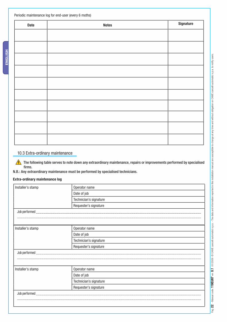
10.3 Extra-ordinary maintenance
The following table serves to note down any extraordinary maintenance, repairs or improvements performed by specialised firms.
N.B.: Any extraordinary maintenance must be performed by specialised technicians.
Extra-ordinary maintenance log
Date Notes Signature
Periodic maintenance log for end-user (every 6 moths)
Installer’s stamp Operator name
Date of job
Technician’s signature
Requester’s signature
Job performed __________________________________________________________________________________________________________________________________________________________________________________________
Installer’s stamp Operator name
Date of job
Technician’s signature
Requester’s signature
Job performed __________________________________________________________________________________________________________________________________________________________________________________________
Installer’s stamp Operator name
Date of job
Technician’s signature
Requester’s signature
Job performed __________________________________________________________________________________________________________________________________________________________________________________________
Pag.
2323
- M
anua
l cod
e : 1
19EU
8711
9EU
87 v
er. 0
.10.1
01 /
2009
© C
AME
canc
elli
auto
mat
ici s
.p.a
. - T
he d
ata
and
info
rmat
ion
repo
rted
in th
is in
stal
latio
n m
anua
l are
sus
cept
ible
to c
hang
e at
any
tim
e an
d w
ithou
t obl
igat
ion
on C
AME
canc
elli
auto
mat
ici s
.p.a
. to
notif
y us
ers.
EN
GLIS
H
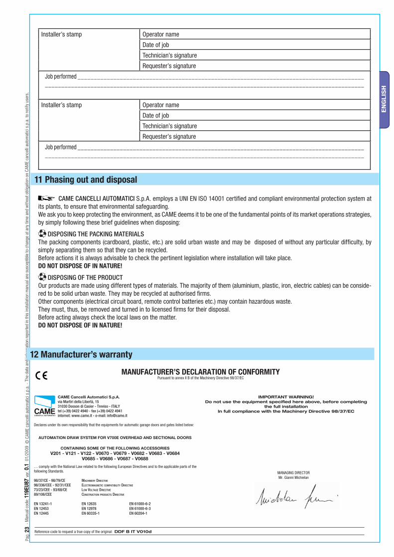
MANUFACTURER’S DECLARATION OF CONFORMITYPursuant to annex II B of the Machinery Directive 98/37/EC
CAME Cancelli Automatici S.p.A. via Martiri della Libertà, 15 31030 Dosson di Casier - Treviso - ITALY tel (+39) 0422 4940 - fax (+39) 0422 4941 internet: www.came.it - e-mail: [email protected]
Declares under its own responsibility that the equipments for automatic garage doors and gates listed below:
… comply with the National Law related to the following European Directives and to the applicable parts of the following Standards.
98/37/CE - 98/79/CE MACHINERY DIRECTIVE 98/336/CEE - 92/31/CEE ELECTROMAGNETIC COMPATIBILITY DIRECTIVE
73/23/CEE - 93/68/CE LOW VOLTAGE DIRECTIVE
89/106/CEE CONSTRUCTION PRODUCTS DIRECTIVE
EN 13241-1 EN 12635 EN 61000-6-2 EN 12453 EN 12978 EN 61000-6-3 EN 12445 EN 60335-1 EN 60204-1
IMPORTANT WARNING!Do not use the equipment specifi ed here above, before completing
the full installationIn full compliance with the Machinery Directive 98/37/EC
MANAGING DIRECTORMr. Gianni Michielan
12 Manufacturer’s warranty
Reference code to request a true copy of the original: DDF B IT V010d
AUTOMATION DRAW SYSTEM FOR V700E OVERHEAD AND SECTIONAL DOORS
CONTAINING SOME OF THE FOLLOWING ACCESSORIESV201 - V121 - V122 - V0670 - V0679 - V0682 - V0683 - V0684
V0685 - V0686 - V0687 - V0688
11 Phasing out and disposal
CAME CANCELLI AUTOMATICI S.p.A. employs a UNI EN ISO 14001 certified and compliant environmental protection system at its plants, to ensure that environmental safeguarding.We ask you to keep protecting the environment, as CAME deems it to be one of the fundamental points of its market operations strategies, by simply following these brief guidelines when disposing:
DISPOSING THE PACKING MATERIALSThe packing components (cardboard, plastic, etc.) are solid urban waste and may be disposed of without any particular difficulty, by simply separating them so that they can be recycled.Before actions it is always advisable to check the pertinent legislation where installation will take place.DO NOT DISPOSE OF IN NATURE!
DISPOSING OF THE PRODUCTOur products are made using different types of materials. The majority of them (aluminium, plastic, iron, electric cables) can be conside-red to be solid urban waste. They may be recycled at authorised firms. Other components (electrical circuit board, remote control batteries etc.) may contain hazardous waste. They must, thus, be removed and turned in to licensed firms for their disposal.Before acting always check the local laws on the matter.DO NOT DISPOSE OF IN NATURE!
Installer’s stamp Operator name
Date of job
Technician’s signature
Requester’s signature
Job performed __________________________________________________________________________________________________________________________________________________________________________________________
Installer’s stamp Operator name
Date of job
Technician’s signature
Requester’s signature
Job performed __________________________________________________________________________________________________________________________________________________________________________________________
CAME France S.a.CAME France S.a.7, Rue Des HarasZ.i. Des Hautes Patures92737 Nanterre Cedex - Nanterre Cedex - FRANCE
(+33) 1 46 13 05 05 (+33) 1 46 13 05 00
CAME Gmbh SeefeldCAME Gmbh SeefeldAkazienstrasse, 9
16356 Seefeld Seefeld Bei Berlin - DEUTSCHLAND
(+49) 33 3988390 (+49) 33 39883985
CAME Automatismes S.a.CAME Automatismes S.a.3, Rue Odette Jasse13015 Marseille - Marseille - FRANCE
(+33) 4 95 06 33 70 (+33) 4 91 60 69 05
CAME GmbhCAME GmbhKornwestheimer Str. 37
70825 Korntal Korntal Munchingen Bei Stuttgart - DEUTSCHLAND
(+49) 71 5037830 (+49) 71 50378383
CAME Automatismos S.a.CAME Automatismos S.a.C/juan De Mariana, N. 17-local28045 Madrid - Madrid - SPAIN
(+34) 91 52 85 009 (+34) 91 46 85 442
CAME Americas Automation LlcCAME Americas Automation Llc1560 Sawgrass Corporate Pkwy, 4th Floor
SunriseSunrise, FL 33323 - U.S.A (+1) 305 433 3307 (+1) 305 396 3331
CAME Automatismos Catalunya S.a.CAME Automatismos Catalunya S.a.P.i. Moli Dels Frares N. 23 C/a08620 Sant Vicenc Del Horts - Sant Vicenc Del Horts - SPAIN
(+34) 93 65 67 694 (+34) 93 67 24 505
CAME Middle East FzcoCAME Middle East FzcoPo Box 17131 Warehouse N. Be02
South Zone - Jebel Ali Free Zone - Dubai - Dubai - U.A.E. (+971) 4 8860046 (+971) 4 8860048
Paf - CAMEPaf - CAMEEstrada Nacional 249-4 Ao Km 4,35Cabra Figa - Trajouce2635-047 Rio De Mouro - Rio De Mouro - PORTUGAL
(+351) 219 257 471 (+35) 219 257 485
CAME Polska Sp.Zo.oCAME Polska Sp.Zo.oUl. Ordona 1
01-237 Warszawa - Warszawa - POLAND (+48) 22 8365076 (+48) 22 8363296
CAME United Kingdom Ltd.CAME United Kingdom Ltd.Unit 3 Orchard Business ParkTown Street, SandiacreNottingham Nottingham - Ng10 5du - UNITED KINGDOM
(+44) 115 9210430 (+44) 115 9210431
S.c. CAME Romania S.r.l.S.c. CAME Romania S.r.l.B-dul Mihai Eminescu, Nr. 2, Bloc R2
Scara A, Parter, Ap. 3Buftea, Judet Ilfov Bucarest - Bucarest - ROMANIA
(+40) 21 3007344 (+40) 21 3007344
CAME Belgium SprlCAME Belgium SprlZoning Ouest 77860 Lessines - Lessines - BELGIUM
(+32) 68 333014 (+32) 68 338019
CAME RussiaCAME RussiaLeningradskij Prospekt, Dom 80
Pod’ezd 3, offi ce 608125190, MoskvaMoskva - RUSSIA
(+7) 495 937 33 07 (+7) 495 937 33 08
CAME Cancelli Automatici S.p.a.CAME Cancelli Automatici S.p.a.Via Martiri Della Libertà, 1531030 Dosson Di Casier Dosson Di Casier (Tv)
(+39) 0422 4940 (+39) 0422 4941
Informazioni Commerciali 800 848095www.came.it
CAME Nord s.r.l.CAME Nord s.r.l.Piazza Castello, 16
20093 Cologno Monzese Cologno Monzese (MI) (+39) 02 26708293 (+39) 02 25490288
CAME Service Italia S.r.l.CAME Service Italia S.r.l.Via Della Pace, 2831030 Dosson Di Casier Dosson Di Casier (Tv)
(+39) 0422 383532 (+39) 0422 490044
Assistenza Tecnica 800 295830Assistenza Tecnica 800 295830
CAME Sud s.r.l.CAME Sud s.r.l.Via F. Imparato, 198
Cm2 Lotto A/7 80146 Napoli Napoli
(+39) 081 7524455 (+39) 081 7529109
Engl
ish
Engl
ish
- M
anua
l cod
e: ..
......
......
......
.. v
er. .
..... .
./....
© C
AME
canc
elli
auto
mat
ici s
.p.a
. Th
e da
ta a
nd in
form
atio
n re
port
ed in
this
inst
alla
tion
man
ual a
re s
usce
ptib
le to
cha
nge
at a
ny ti
me
and
with
out o
blig
atio
n on
CAM
E ca
ncel
li au
tom
atic
i s.p
.a. t
o no
tify
user
s.