Embed Size (px)
Citation preview
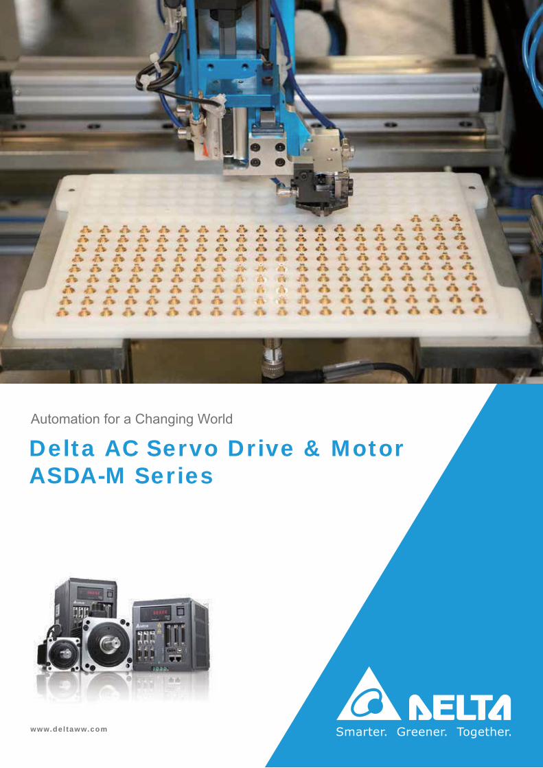
Delta AC Servo Drive & MotorASDA-M Series
www.del taww.com
Automation for a Changing World
1
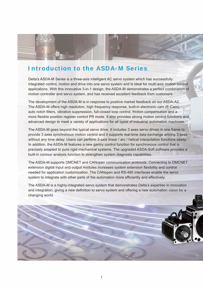
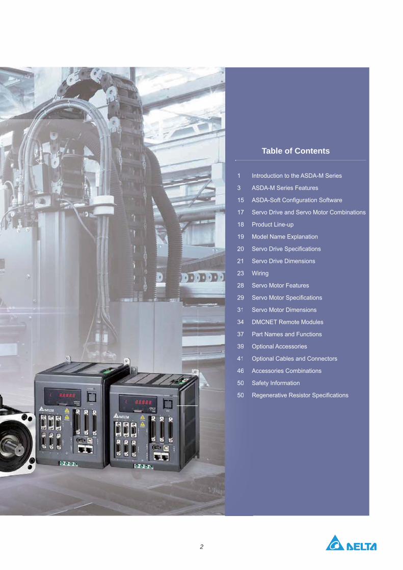
Delta's ASDA-M Series is a three-axis intelligent AC servo system which has successfully integrated control, motion and drive into one servo system and is ideal for multi-axis motion control applications. With this innovative 3-in-1 design, the ASDA-M demonstrates a perfect combination of motion controller and servo system, and has received excellent feedback from customers.
The development of the ASDA-M is in response to positive market feedback on our ASDA-A2. The ASDA-M offers high resolution, high frequency response, built-in electronic cam (E-Cam),
advanced design to meet a variety of applications for all types of industrial automation machines.
provide 3 axes synchronous motion control and it supports real-time data exchange among 3 axes without any time delay. Users can perform 3-axis linear / arc / helical interpolation functions easily.
precisely adapted to pure rigid mechanical systems. The upgraded ASDA-Soft software provides a built-in contour analysis function to strengthen system diagnosis capabilities.
The ASDA-M supports DMCNET and CANopen communication protocols. Connecting to DMCNET
The ASDA-M is a highly-integrated servo system that demonstrates Delta’s expertise in innovation
changing world.
Introduction to the ASDA-M Series
apabilities.
otocols. Conn
s Delta’s exp
necting to DMCNET
pertisese in innovation
2
1
3
17
19
20
21
23
29
31
37
39
31
37
39
Table of Contents
ASDA-M Series Features
Servo Drive and Servo Motor Combinations
Model Name Explanation
Servo Drive Dimensions
Wiring
Servo Motor Features
Servo Motor Dimensions
Optional Accessories
Optional Cables and Connectors
Accessories Combinations
3
DT3
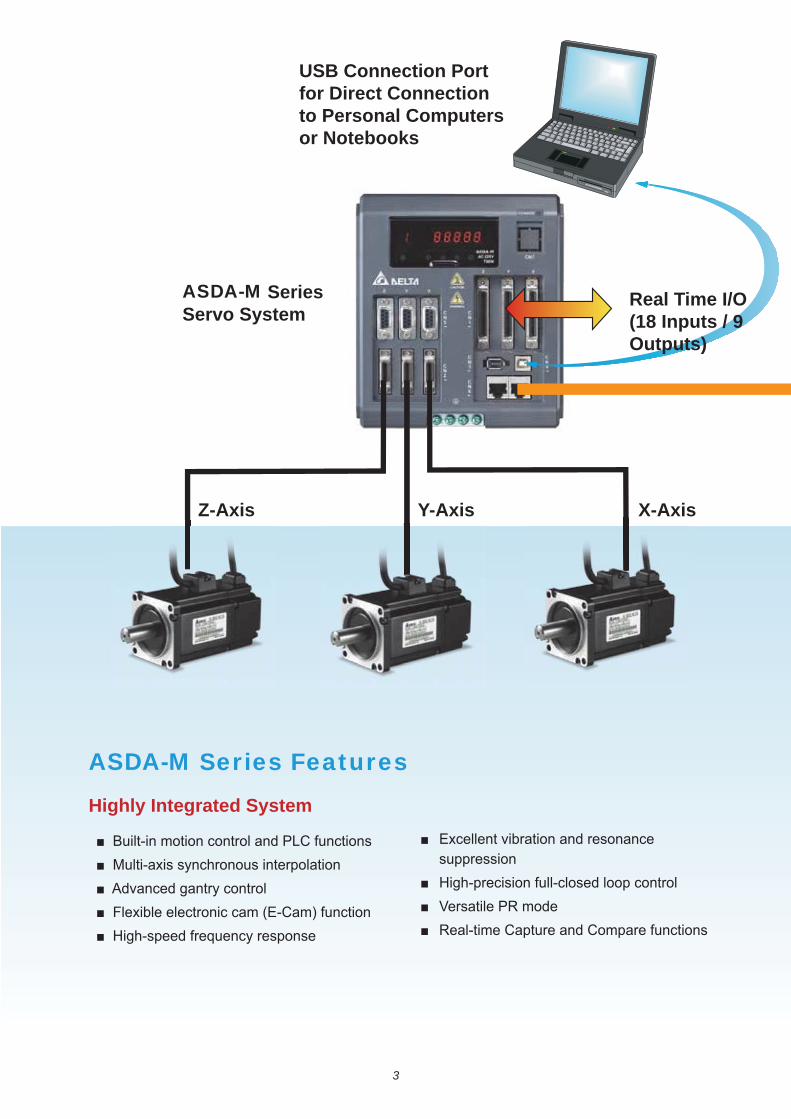
ASDA-M Series Features
ASDA-M Series Servo System
Real Time I/O (18 Inputs / 9 Outputs)
USB Connection Port for Direct Connection to Personal Computers or Notebooks
Z-Axis Y-Axis X-Axis
Highly Integrated System
suppression
4
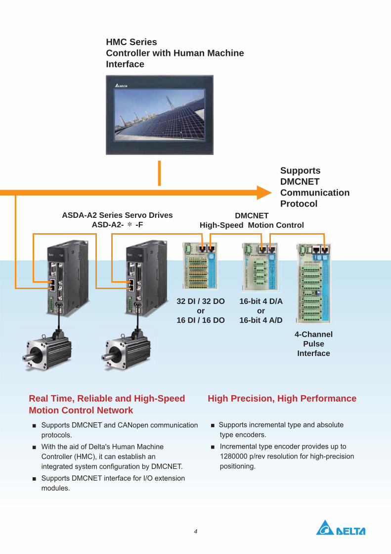
HMC SeriesController with Human Machine Interface
ASDA-A2 Series Servo DrivesASD-A2-* -F
DMCNET High-Speed Motion Control
Supports DMCNET Communication Protocol
32 DI / 32 DO or
16 DI / 16 DO
16-bit 4 D/Aor
16-bit 4 A/D
4-Channel Pulse
Interface
protocols.
modules.
High Precision, High Performance
type encoders.
positioning.
Real Time, Reliable and High-Speed Motion Control Network
5
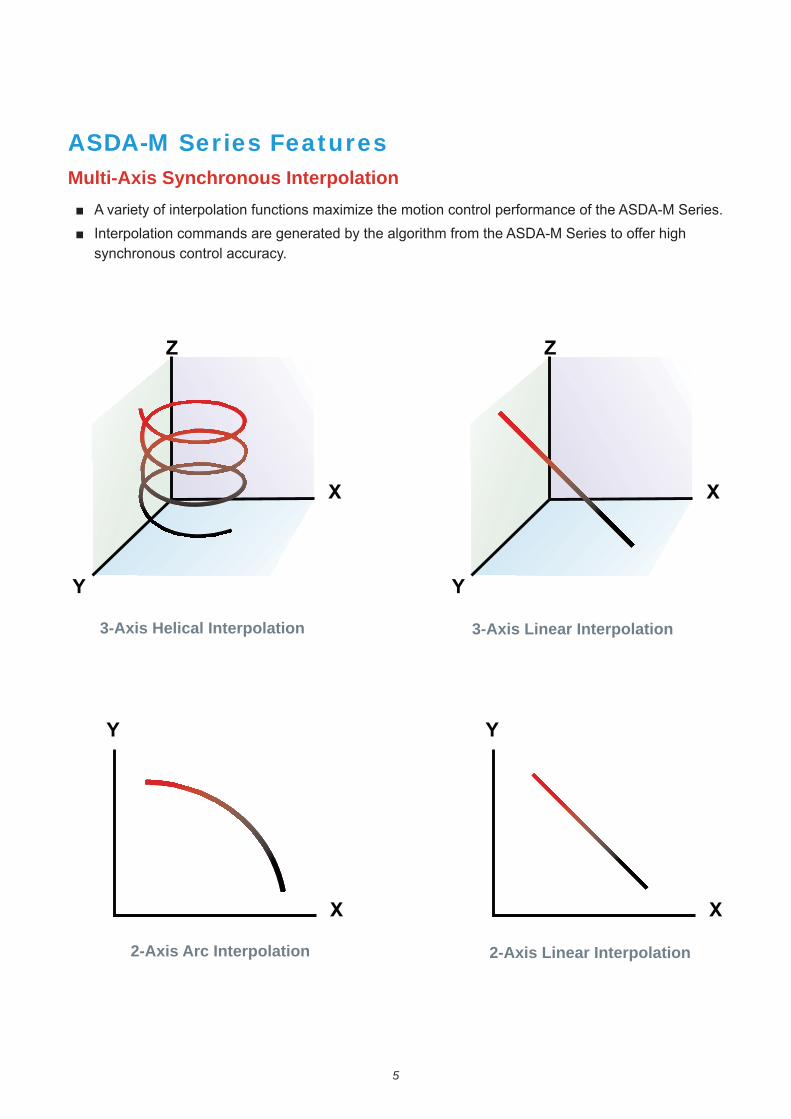
ASDA-M Series FeaturesMulti-Axis Synchronous Interpolation
synchronous control accuracy.
3-Axis Linear Interpolation3-Axis Helical Interpolation
2-Axis Arc Interpolation 2-Axis Linear Interpolation

6
commands are exchanged between Axis 1 and Axis 2 every
Excellent Synchronous Control
Advanced Gantry Control
the ASDA-M Series can perform precise motion control and drive each axis simultaneously.
Axis 1 Axis 2
Gantry Control

7
ASDA-M Series Features
Distributed Motion Control System - HMC Series serves as a Master
Provides an integrated development environment
HMC SeriesController with Human Machine Interface
Real Time I / O (18 Inputs / 9 Outputs )
ASDA-M Series Servo SystemASD-M-* -F
Ethernet
RS-485
High speed RS-422 (10 Mbps)
I / O Module
I / O Module
Pulse Input
DMCNET High-Speed Motion Control
32 DI / 32 DO or
16 DI / 16 DO
Manual Pulse Generator (MPG)
ECMA Series Servo Motors
Z- Axis Y- Axis X- Axis
within 1ms.
combination of distributed systems to increase effectiveness.

8
Contour Analysis Function in ASDA-Soft
Contour Test Contour analysis of position feedback signals between two servo motors
9
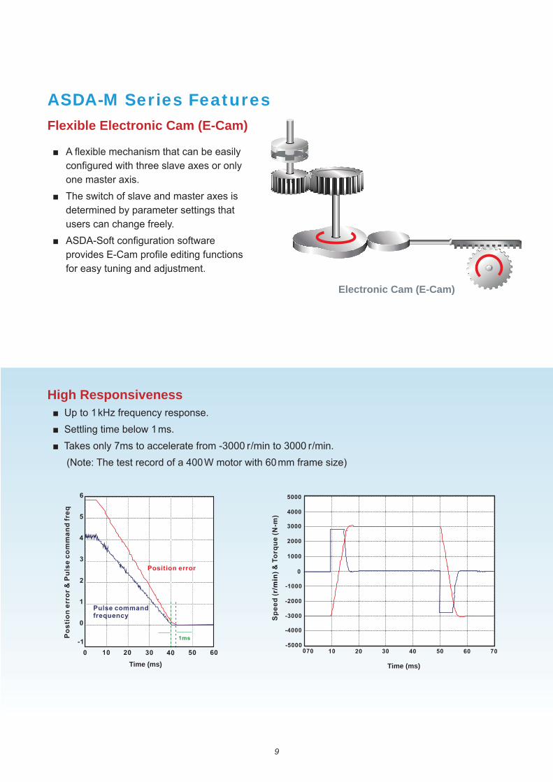
ASDA-M Series FeaturesFlexible Electronic Cam (E-Cam)
High Responsiveness
3000 r/min to 3000 r/min.
one master axis.
determined by parameter settings that users can change freely.
Electronic Cam (E-Cam)
Time (ms) Time (ms)
10
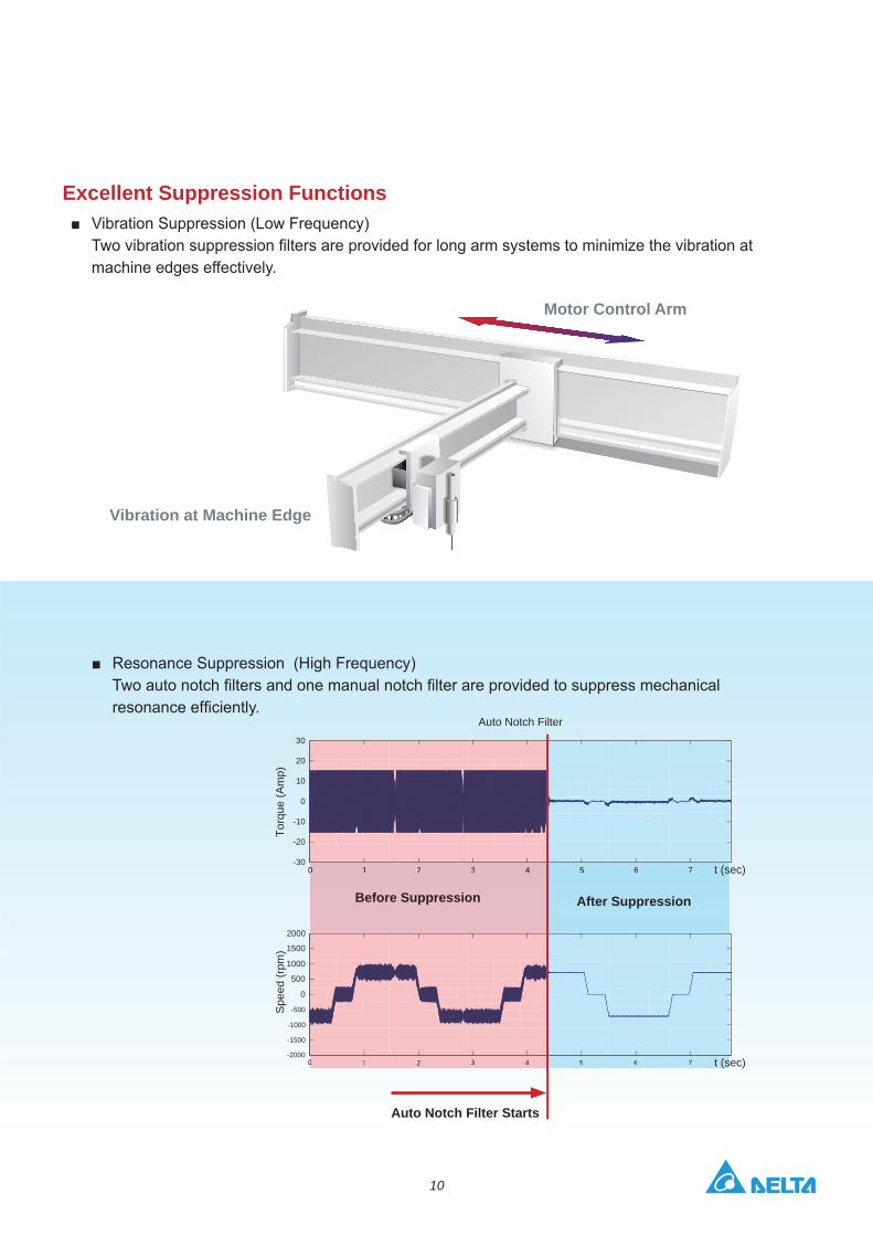
Excellent Suppression Functions
machine edges effectively.
0 1 2 3 4 5 6 7-30
-20
-10
0
10
20
30
Torq
ue (A
mp)
Auto Notch Filter
0 1 2 3 4 5 6 7-2000
-1500
-1000
-500
0
500
1000
1500
2000
Spe
ed (r
pm)
0 1 2 3 4
0 1 2 3 4 5 6 7
5 6 7
t (sec)
t (sec)
Motor Control Arm
Vibration at Machine Edge
Before Suppression After Suppression
Auto Notch Filter Starts
11
ASDA-M Series Features
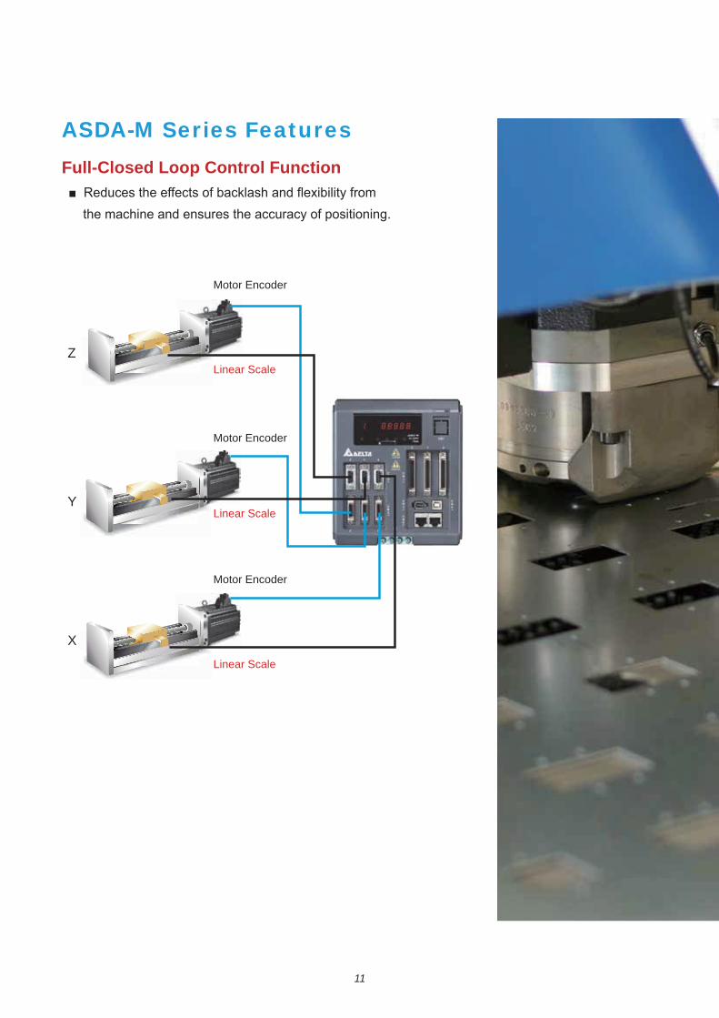
Full-Closed Loop Control Function
the machine and ensures the accuracy of positioning.
Motor Encoder
Motor Encoder
Motor Encoder
Linear Scale
Linear Scale
Linear Scale
X
Y
Z

12
Versatile PR Mode
continuous position control.
instantaneously.
accuracy and variable speed.
position mode / Multi-axis linear interpolation mode / 2-Axis arc interpolation mode / 3-Axis helical
commands for accurate positioning control.
moment it is inserted.
Sequential Command
P_Command 1 P_Command 1 P_Command 2 P_Command 2
Overlap Command
A command is executed only when the previous command is completed.
The second command is executed after the delay time or during the deceleration period.
Insertion Command
P_Command 1
External command triggered
P_Command 2
13
ASDA-M Series FeaturesReal Time Capture and Compare Functions Position Latch Function (Capture)
.
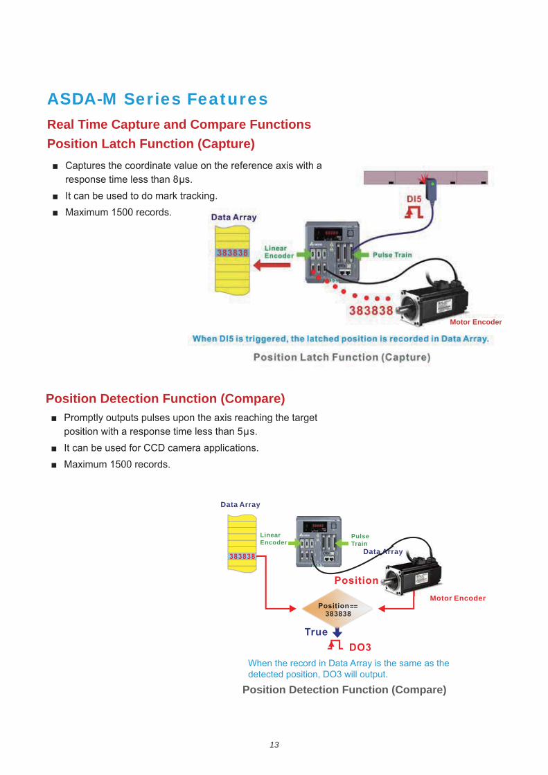
Position Detection Function (Compare)
.
When the record in Data Array is the same as the detected position, DO3 will output.
Motor Encoder
Position Detection Function (Compare)
==
Data Array
Data Array
Linear Encoder
Pulse Train
Motor Encoder
14
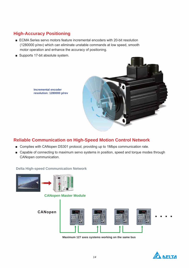
High-Accuracy Positioning
motor operation and enhance the accuracy of positioning.
Reliable Communication on High-Speed Motion Control Network
CANopen communication.
Incremental encoder resolution: 1280000 p/rev
Maximum 127 axes systems working on the same bus
Delta High-speed Communication Network
CANopen Master Module
15
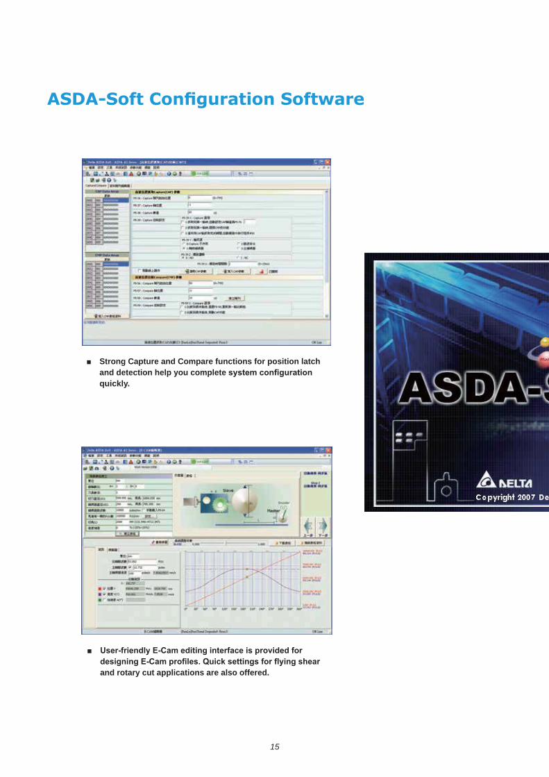
Strong Capture and Compare functions for position latch and detection help you complete quickly.
and rotary cut applications are also offered.

16
digital oscilloscope is able to quickly record the status and data of each axis. Real-time monitoring is easy.
troubleshooting the system easily and recommending timely corrective actions.
enhanced PR control mode. Homing, point-to-point and other motion control functions for multi-axis positioning control are easy to achieve.
17
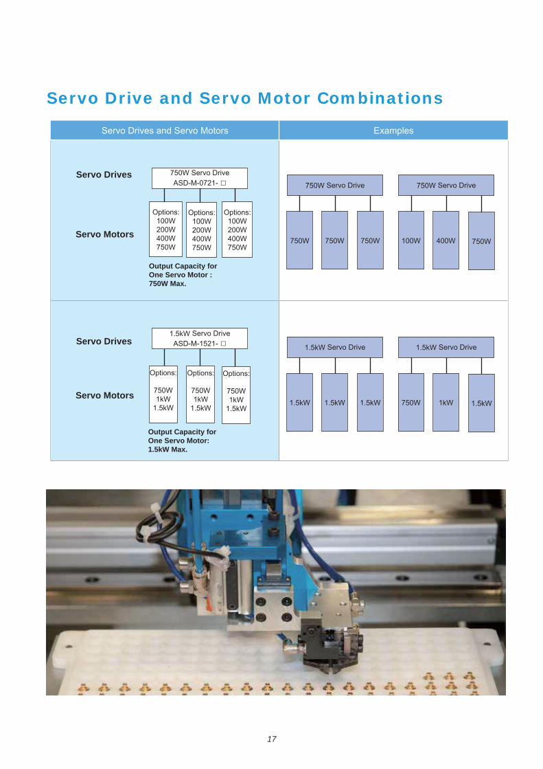
Servo Drives and Servo Motors Examples
ASD-M-0721-
Options:100W200W400W750W
Options:100W200W400W750W
Options:100W200W400W750W
Output Capacity for One Servo Motor : 750W Max.
Output Capacity for One Servo Motor: 1.5kW Max.
Servo Drives
Servo Drives
Servo Motors
Servo Motors
1.5kW Servo Drive ASD-M-1521-
Options:
750W1kW
1.5kW
Options:
750W1kW
1.5kW
Options:
750W1kW
1.5kW
750W Servo Drive
750W 750W 750W
750W Servo Drive
100W 400W 750W
1.5kW Servo Drive
1.5kW 1.5kW 1.5kW
1.5kW Servo Drive
750W 1kW 1.5kW
Servo Drive and Servo Motor Combinations
18
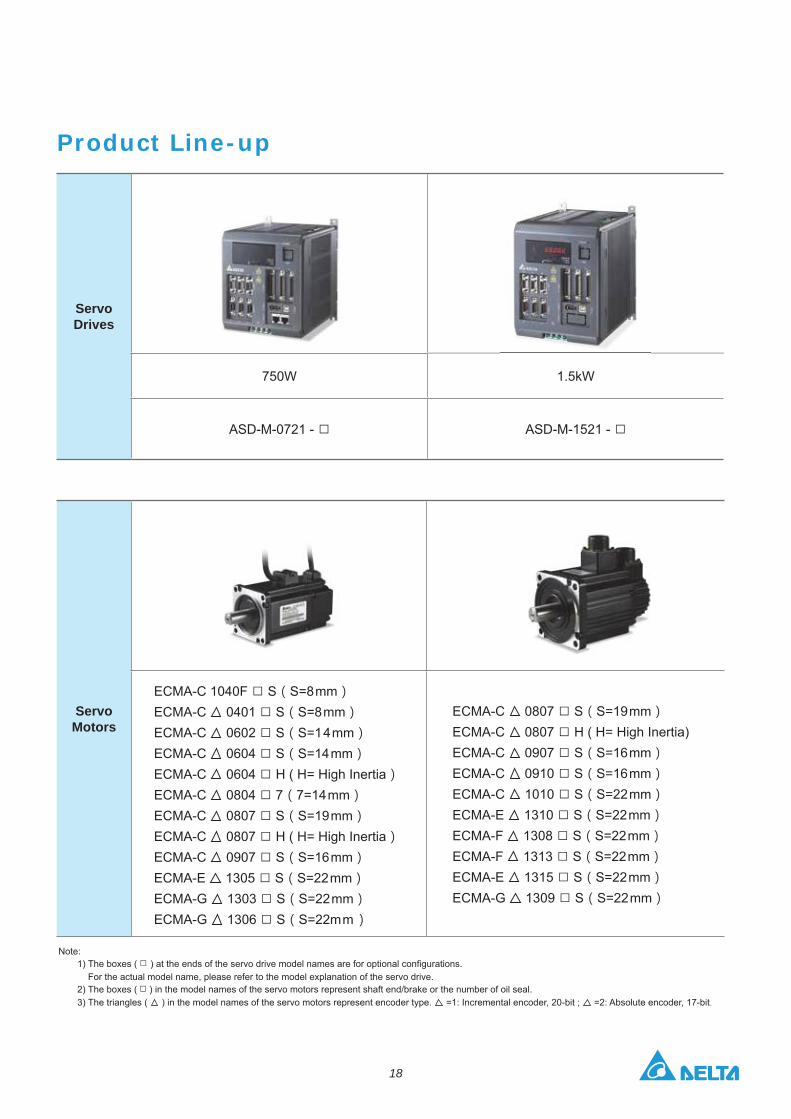
Servo Motors
ECMA-C 1040F S S=8mmECMA-C 0401 S S=8mmECMA-C 0602 S S=14mmECMA-C 0604 S S=14mmECMA-C 0604 H ( H= High InertiaECMA-C 0804 7 7=14mmECMA-C 0807 S S=19mmECMA-C 0807 H ( H= High InertiaECMA-C 0907 S S=16mmECMA-E 1305 S S=22mmECMA-G 1303 S S=22mmECMA-G 1306 S S=22mm
ECMA-C 0807 S S=19mmECMA-C 0807 H ( H= High Inertia)ECMA-C 0907 S S=16mmECMA-C 0910 S S=16mmECMA-C 1010 S S=22mmECMA-E 1310 S S=22mmECMA-F 1308 S S=22mm ECMA-F 1313 S S=22mmECMA-E 1315 S S=22mmECMA-G 1309 S S=22mm
Product Line-up
Servo Drives
750W 1.5kW
ASD-M-0721 - ASD-M-1521 -
Note:1) The boxes (
For the actual model name, please refer to the model explanation of the servo drive.2) The boxes ( ) in the model names of the servo motors represent shaft end/brake or the number of oil seal. 3) The triangles ( ) in the model names of the servo motors represent encoder type. =2: Absolute encoder, 17-bit.
19
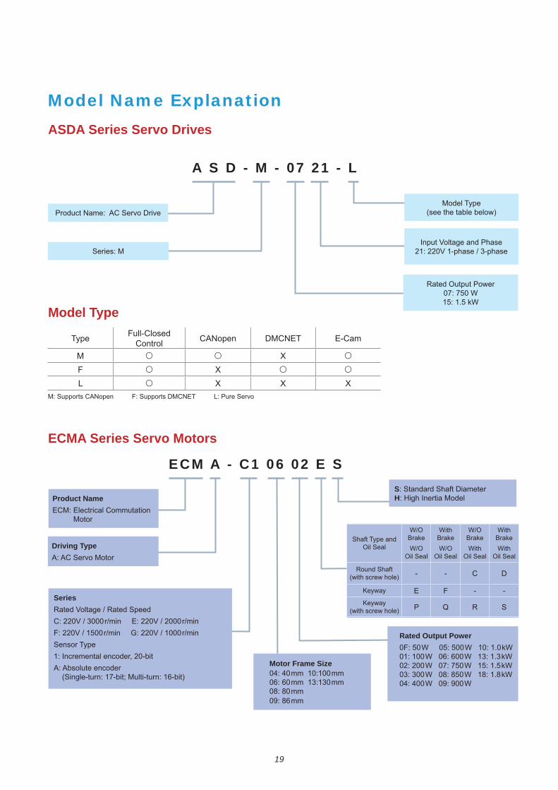
Model Name Explanation
ASDA Series Servo Drives
Model Type
A S D - M - 07 21 - L
Series: M
Model Type (see the table below)
Input Voltage and Phase21: 220V 1-phase / 3-phase
Rated Output Power07: 750 W 15: 1.5 kW
Type Full-ClosedControl CANopen DMCNET E-Cam
M XF XL X X X
M: Supports CANopen F: Supports DMCNET L: Pure Servo
ECMA Series Servo Motors
ECM A - C1 06 02 E S
Product NameECM: Electrical Commutation Motor
Driving TypeA: AC Servo Motor
S: Standard Shaft DiameterH: High Inertia Model
Rated Output Power0F: 50W 05: 500W 10: 1.0kW01: 100W 06: 600W 13: 1.3kW02: 200W 07: 750W 15: 1.5kW03: 300W 08: 850W 18: 1.8kW04: 400W 09: 900W
SeriesRated Voltage / Rated SpeedC: 220V / 3000r/min E: 220V / 2000r/minF: 220V / 1500r/min G: 220V / 1000r/minSensor Type1: Incremental encoder, 20-bitA: Absolute encoder (Single-turn: 17-bit; Multi-turn: 16-bit)
Motor Frame Size04: 40mm 10:100mm 06: 60mm 13:130mm 08: 80mm 09: 86mm
Shaft Type and Oil Seal
W/O
W/O Oil Seal
With
W/O Oil Seal
W/O
With Oil Seal
With
With Oil Seal
(with screw hole) - - C D
Keyway E F - -Keyway
(with screw hole) P Q R S
20
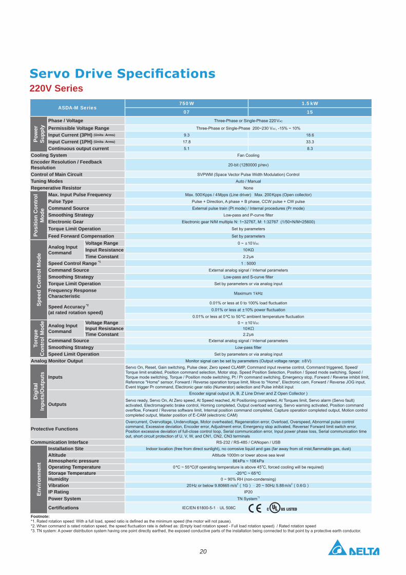
220V Series
ASDA-M Series750 W 1.5 kW
07 15
Pow
er
Supp
ly
Phase / Voltage Three-Phase or Single-Phase 220 VAC
Permissible Voltage Range Three-Phase or Single-Phase 200~230 VAC, -15% ~ 10%
Input Current (3PH) 9.3 18.6
Input Current (1PH) 17.8 33.3
Continuous output current 5.1 8.3
Cooling System Fan Cooling
Encoder Resolution / Feedback Resolution 20-bit (1280000 p/rev)
Control of Main Circuit SVPWM (Space Vector Pulse Width Modulation) Control
Tuning Modes Auto / Manual
Regenerative Resistor None
Posi
tion
Con
trol
M
ode
Max. Input Pulse Frequency Max. 500 Kpps / 4 Mpps (Line driver) Max. 200 Kpps (Open collector)
Pulse Type Pulse + Direction, A phase + B phase, CCW pulse + CW pulse
Command Source External pulse train (Pt mode) / Internal procedures (Pr mode)
Smoothing StrategyElectronic Gear Electronic gear N/M multiple N: 1~32767, M: 1:32767 (1/50<N/M<25600)
Torque Limit Operation Set by parameters
Feed Forward Compensation Set by parameters
Spee
d C
ontr
ol M
ode
Analog Input Command
Voltage Range 0 ~ 10 VDC
Input Resistance 10 K
Time Constant 2.2
Speed Control Range *1 1 : 5000
Command Source External analog signal / Internal parameters
Smoothing StrategyTorque Limit Operation Set by parameters or via analog input
Frequency Response Characteristic Maximum 1 kHz
Speed Accuracy *2
(at rated rotation speed) 0.01% or less at
Torq
ue
Con
trol
Mod
e Analog Input Command
Voltage Range 0 ~ 10 VDC
Input Resistance 10 KTime Constant 2.2
Command Source External analog signal / Internal parameters
Smoothing StrategySpeed Limit Operation Set by parameters or via analog input
Analog Monitor Output Monitor signal can be set by parameters (Output voltage range: 8 V)
Dig
ital
Inpu
ts/O
utpu
ts Inputs
Servo On, Reset, Gain switching, Pulse clear, Zero speed CLAMP, Command input reverse control, Command triggered, Speed/Torque limit enabled, Position command selection, Motor stop, Speed Position Selection, Position / Speed mode switching, Speed / Torque mode switching, Torque / Position mode switching, Pt / Pr command switching, Emergency stop, Forward / Reverse inhibit limit, Reference "Home" sensor, Forward / Reverse operation torque limit, Move to "Home", Electronic cam, Forward / Reverse JOG input, Event trigger Pr command, Electronic gear ratio (Numerator) selection and Pulse inhibit input
Outputs
Encoder signal output (A, B, Z Line Driver and Z Open Collector )
Servo ready, Servo On, At Zero speed, At Speed reached, At Positioning completed, At Torques limit, Servo alarm (Servo fault) activated, Electromagnetic brake control, Homing completed, Output overload warning, Servo warning activated, Position command
completed output, Master position of E-CAM (electronic CAM)
Protective FunctionsOvercurrent, Overvoltage, Undervoltage, Motor overheated, Regeneration error, Overload, Overspeed, Abnormal pulse control command, Excessive deviation, Encoder error, Adjustment error, Emergency stop activated, Reverse/ Forward limit switch error, Position excessive deviation of full-close control loop, Serial communication error, Input power phase loss, Serial communication time out, short circuit protection of U, V, W, and CN1, CN2, CN3 terminals
Communication Interface RS-232 / RS-485 / CANopen / USB
Envi
ronm
ent
Installation SiteAltitude Altitude 1000m or lower above sea levelAtmospheric pressure 86 kPa ~ 106 kPaOperating Temperature 0 ºC ~ 55 ºC(If operating temperature is above 45oC, forced cooling will be required)Storage Temperature -20 ºC ~ 65 ºC Humidity 0 ~ 90% RH (non-condensing)Vibration 20 Hz or below 9.80665 m/s2 1G 20 ~ 50Hz 5.88 m/s2 0.6 GIP Rating IP20
Power System TN System*3
IEC/EN 61800-5-1 UL 508C
Footnote:*1. *2. *3. TN system: A power distribution system having one point directly earthed, the exposed conductive parts of the installation being connected to that point by a protective earth conductor.
21
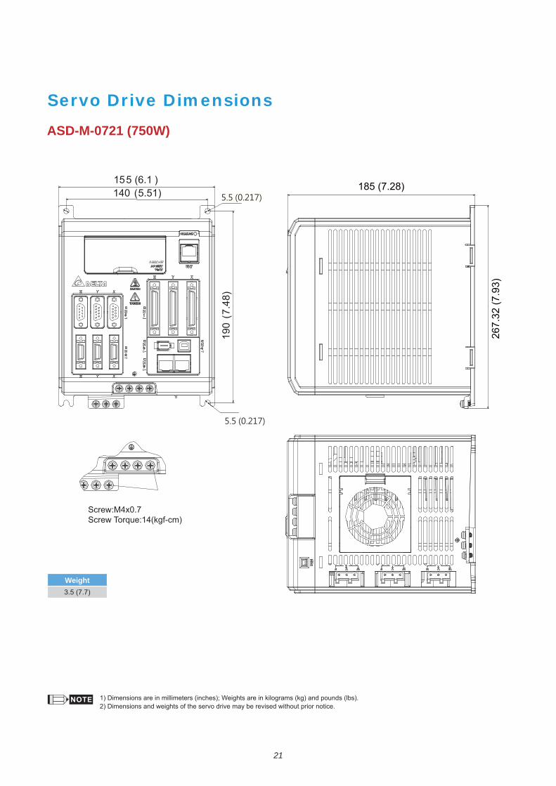
Servo Drive Dimensions
ASD-M-0721 (750W)
1) Dimensions are in millimeters (inches); Weights are in kilograms (kg) and pounds (lbs).2) Dimensions and weights of the servo drive may be revised without prior notice.
Weight
185 (7.28)
267.
32 (7
.93)
190
(7.
48)
140 (5.51) 5.5 (0.217)
155 (6.1 )
22
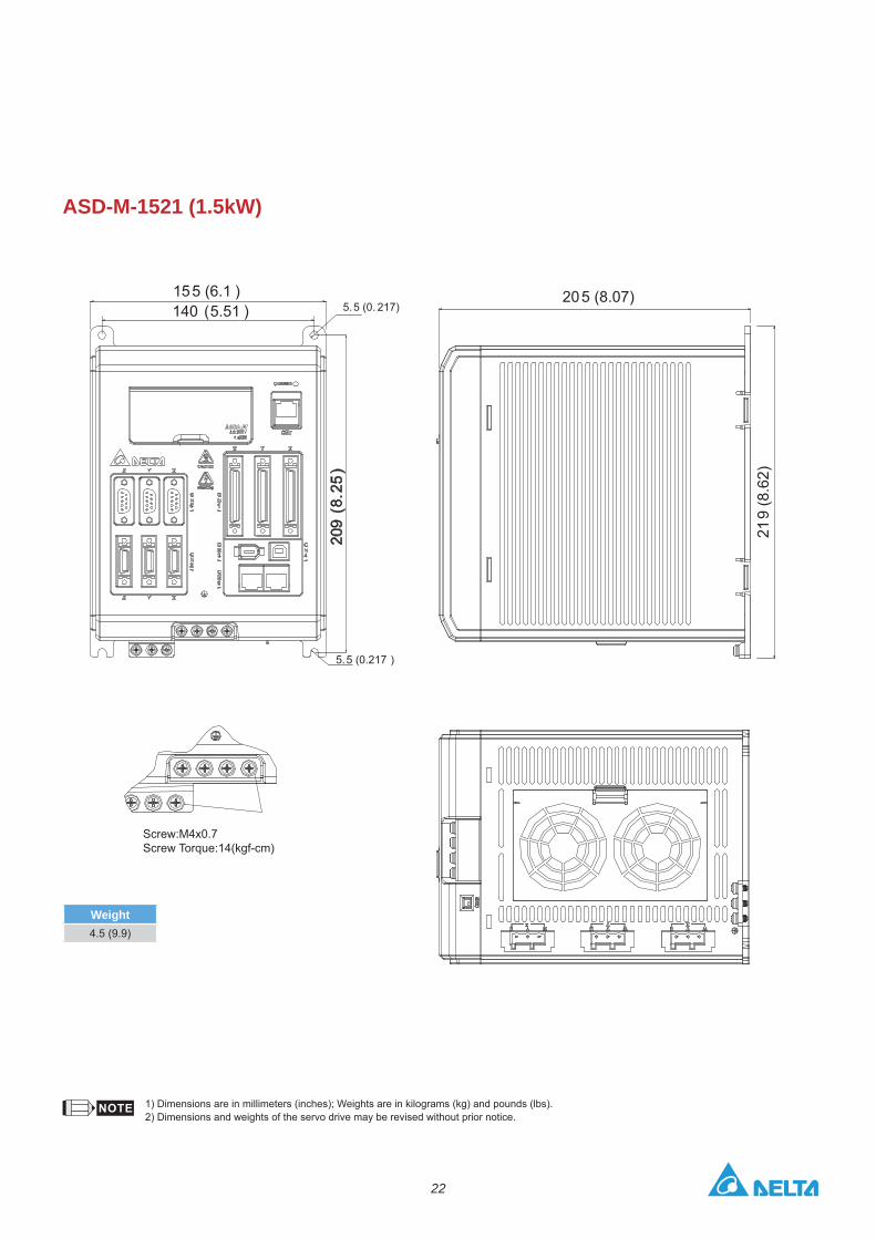
ASD-M-1521 (1.5kW)
1) Dimensions are in millimeters (inches); Weights are in kilograms (kg) and pounds (lbs).2) Dimensions and weights of the servo drive may be revised without prior notice.
Weight
140 (5.51 )155 (6.1 )
209
(8.
25)
5.5 (0. 217)
5.5 (0.217 )
205 (8.07)
219
(8.6
2)
23
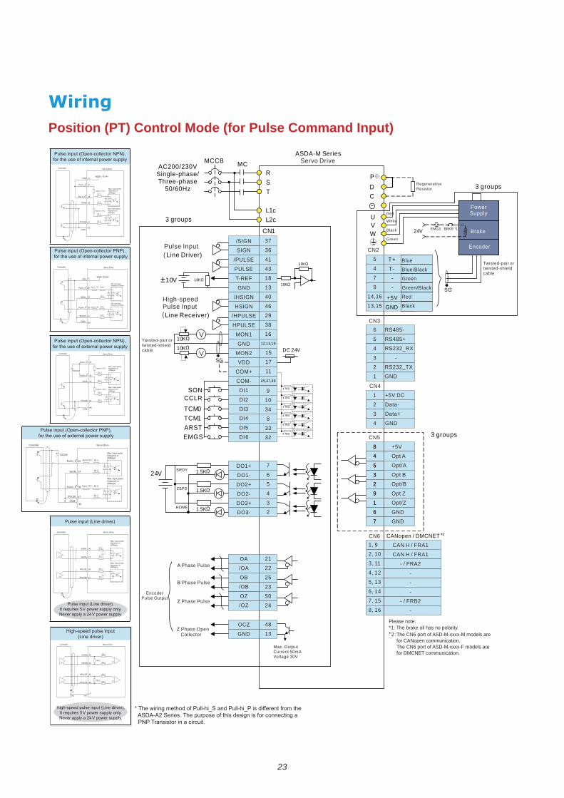
Position (PT) Control Mode (for Pulse Command Input)
High-speed pulse input (Line driver)
Pulse input (Open-collector NPN), for the use of internal power supply
Pulse input (Open-collector PNP), for the use of internal power supply
Pulse input (Open-collector NPN), for the use of external power supply
for the use of external power supply
Pulse input (Line driver)
Pulse input (Line driver).It requires 5 V power supply only.Never apply a 24 V power supply.
High-speed pulse input (Line driver).It requires 5 V power supply only.Never apply a 24 V power supply.
DC24V
51
51
51
1K
1K
Max. Input pulse frequency is200Kpps
Max. Input pulse frequency is200Kpps
51
SG
COM-
/SIGN
/PULSE
Pull-hi_S
VDD 17
35
45
37
41
Controller Servo Drive
Pull-hi_P 39
DC24V
51
51
51
51
SG COM-
/SIGN
/PULSE
VDD 17
35
45
37
41
39Pull-hi_P
Pull-hi_S
Controller Servo Drive
Max. Input pulse frequency is 200Kpps
Max. Input pulse frequency is 200Kpps
1K
1K
DC24V51
51
51
51
SG
COM-
/SIGN
/PULSE
Pull-hi_S 35
45
37
41
Pull-hi_P 39
+-
Controller Servo Drive
1K
1K
Max. Input pulse frequency is 200Kpps
Max. Input pulse frequency is 200Kpps
1K 51
51
51
51SG
COM-
/SIGN
/PULSE
35
45
37
41
39Pull-hi_P
Pull-hi_S
DC24V+-
Controller Servo Drive
Max. Input pulse frequency is 200Kpps
Max. Input pulse frequency is 200Kpps
Approx.
1KApprox.
51
51
51
51
SG
/SIGN
/PULSE
SIGN 36
37
43 PULSE
41
Controller Servo Drive
Max. Input pulse frequency is 200Kpps
Max. Input pulse frequency is 200Kpps
2K
2K
2K
2K
SG
/HSIGN
/HPULSE
HSIGN 46
40
38 HPULSE
29
100
100
GNDGND13
Controller Servo Drive
* The wiring method of Pull-hi_S and Pull-hi_P is different from the ASDA-A2 Series. The purpose of this design is for connecting a PNP Transistor in a circuit.
SIGN/SIGN
12,13,19
45,47,49
T+
T-
-
+5V
-
GND
CN1
PDC
UVW
RST
L1cL2c
MCMCCBAC200/230V
Single-phase/Three-phase
50/60Hz
ASDA-M SeriesServo Drive
SONCCLRTCM0TCM1ARSTEMGS
1.5K
1.5K
1.5K
SRDY
ZSPD
HOME
24V
A Phase Pulse
Z
Phase Open Collector
10K
10K
Pulse InputLine Driver)
10K10V
High-speed Pulse InputLine Receiver)
10K
10K
DC 24V
SG
SG
Brake
Power Supply
Encoder
24V
3 groups
3 groups
3 groups
CANopen / DMCNET
Regenerative Resistor
Twisted-pair or twisted-shield cable
Encoder Pulse Output
RS485-
RS485+
RS232_RX
-
RS232_TX
GND
6
5
4
3
2
1
+5V DC
Data-
Data+
GND
CN3
5
4
7
9
14,16
13,15
CN2
CN41
2
3
4
CN5
8
4
5
3
2
9
1
6
7
+
Opt B
Opt/B
Opt Z
Opt/Z
GND
5V
Opt A
Opt/A
GND
CN61, 9
2, 10
3, 11
4, 12
5, 13
6, 14
7, 15
8, 16
CAN H / FRA1
CAN H / FRA1
- / FRA2
-
-
-
- / FRB2
-
8
4
5
3
2
9
1
6
7
37
36
41
43
18
13
40
46
29
38
16
15
17
11
9
10
34
8
33
32
7
6
5
4
3
2
21
22
25
23
50
24
48
13
/SIGN
SIGN
/PULSE
PULSE
T-REF
GND
/HSIGN
HSIGN
/HPULSE
HPULSE
MON1
GND
MON2
VDD
COM+
COM-
DI1
DI2
DI3
DI4
DI5
DI 6
DO1+
DO1-
DO2+
DO2-
DO3+
DO3-
OA
/OA
OB
/OB
OZ
/OZ
OCZ
GND
Red
White
Black
Green
Blue
Blue/Black
Green
Green/Black
Black
Red
Twisted-pair or twisted-shield cable
B Phase Pulse
Z Phase Pulse
EMGS BRKR *1
*²
(
(
±
Max. OutputCurrent 50mAVoltage 30V
**1:2:
The CN6 port of ASD-M-xxxx-M models arefor CANopen communication. The CN6 port of ASD-M-xxxx-F models arefor DMCNET communication.
The brake oil has no polarity.Please note:
24
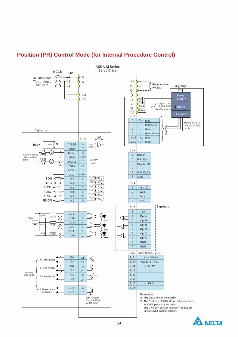
Position (PR) Control Mode (for Internal Procedure Control)
12,13,19
45,47,49
18
13
16
CN1
RST
L1cL2c
MCMCCB
AC200/230V
50/60HzThree-phase
SONCTRGPOS0POS1ARSTEMGS
1.5K
1.5K
1.5K
SRDY
ZSPD
HOME
24V
10K
10K
10K10V10K
10K
DC 24V
SG
PDC
UVW
SG
24V
3 groups
CANH / FRA1
CANL / FRAB1
- / FRA2
-
-
- / FRB2
-
CN2
CN3
6
5
4
3
2
1
RS485-
RS485+
RS232_RX
-
RS232_TX
GND
CN4
1
2
3
4
+5V DC
Data-
Data+
GND
3 groupsCN5
8
4
5
3
2
9
1
6
7
+5V
Opt A
Opt /A
Opt B
Opt /B
Opt Z
Opt /Z
GND
GND
CN61, 9
2, 10
3, 11
4, 12
5, 13
6, 14
7, 15
8, 16
CANopen / DMCNET
3 groups
T-REF
GND
MON1
GND
MON2
VDD
COM+
COM-
DI1
DI2
DI3
DI4
DI5
DI6
DO1+
DO1-
DO2+
DO2-
DO3+
DO3-
OA
/OA
OB
/OB
OZ
/OZ
15
17
11
9
10
34
8
33
32
7
6
5
4
3
2
21
22
25
23
50
24
48
13
OCZ
GND
Twisted-pair ortwisted-shieldcable
RegenerativeResistor
Green
RedWhite
Black
Twisted-pair ortwisted-shieldcable
T+
T-
-
+5V
-
GND
5
4
7
9
14,16
13,15
Blue
Blue/Black
Green
Green/Black
Black
Red
A Phase Pulse
Z Phase OpenCollector
EncoderPulse Output
B Phase Pulse
Z Phase Pulse
Max. OutputCurrent 50mAVoltage 30V
EMGS BRKR *1
*²
±
Brake
Power Supply
Encoder
ASDA-M SeriesServo Drive
**1:2:
The CN6 port of ASD-M-xxxx-M models arefor CANopen communication. The CN6 port of ASD-M-xxxx-F models arefor DMCNET communication.
The brake oil has no polarity.Please note:

25
Speed (S, Sz) Control Mode (for Analog Voltage Input and Internal Parameter Setting)
12,13,19
45,47,49
CN1
RST
L1cL2c
MCMCCB
SONTRQLM
SPD0SPD1ARSTEMGS
1.5K
1.5K
1.5K
SRDY
ZSPD
TSPD
24V
10K
10K
10K10V10K
10K
DC 24V
SG
10K
10K10K10V
PDC
UVW
SG
24V
3 groups
RS485-
RS485+
RS232_RX
-
RS232_TX
GND
6
5
4
3
2
1
CN3
CN2
+5V DC
Data-
Data+
GND
CN4
1
2
3
4
3 groupsCN5+
Opt B
Opt/B
Opt Z
Opt/Z
GND
5V
Opt A
Opt/A
GND
8
4
5
3
2
9
1
6
7
CANopen / DMCNETCN61, 9
2, 10
3, 11
4, 12
5, 13
6, 14
7, 15
8, 16
CAN H / FRA1
CAN H / FRA1
- / FRA2
-
-
-
- / FRB2
-
V-REF
GND
T-REF
GND
MON1
GND
MON2
VDD
COM+
COM-
DI1
DI2
DI3
DI4
DI5
DI16
DO1+
DO1-
DO2+
DO2-
DO3+
DO3-
OA
/OA
OB
/OB
OZ
/OZ
42
44
18
13
16
15
17
11
9
10
34
8
33
32
7
6
5
4
3
2
21
22
25
23
50
24
48
13
OCZ
GND
3 groups
AC200/230V
50/60HzThree-phase
T+
T-
-
+5V
-
GND
5
4
7
9
14,16
13,15
Blue
Blue/Black
Green
Green/Black
Black
Red
Red
White
Black
Green
A Phase Pulse
Z Phase OpenCollector
EncoderPulse Output
B Phase Pulse
Z Phase Pulse
Max. OutputCurrent 50mAVoltage 30V
Twisted-pair ortwisted-shieldcable
Twisted-pair ortwisted-shieldcable
RegenerativeResistor
EMGS BRKR *1
*²
±
±
Brake
Power Supply
Encoder
Please note:**1:2:
The CN6 port of ASD-M-xxxx-M models arefor CANopen communication. The CN6 port of ASD-M-xxxx-F models arefor DMCNET communication.
ASDA-M SeriesServo Drive
The brake oil has no polarity.
26
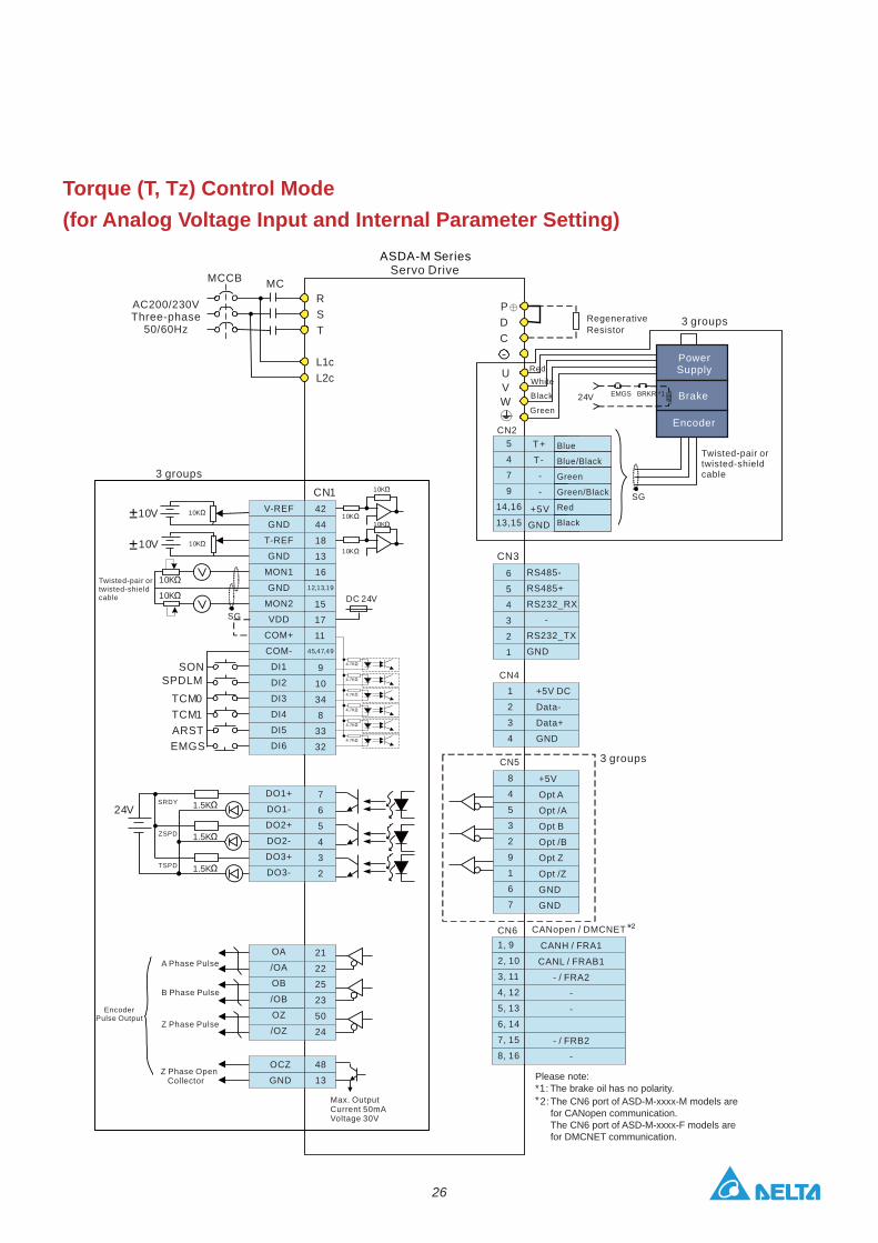
Torque (T, Tz) Control Mode (for Analog Voltage Input and Internal Parameter Setting)
12,13,19
45,47,49
CN1
RST
L1cL2c
MCMCCB
SONSPDLM
TCM0TCM1ARSTEMGS
1.5K
1.5K
1.5K
SRDY
ZSPD
TSPD
24V
10K
10K
10K10V10K
10K
DC 24V
SG
10K
10K10K10V
PDC
UVW
SG
24V
4.7K
4.7K
4.7K
4.7K
4.7K
4.7K
3 groups
CN2
CN36
5
4
3
2
1
RS485-
RS485+
RS232_RX
-
RS232_TX
GND
CN4
1
2
3
4
+5V DC
Data-
Data+
GND
CN5
8
4
5
3
2
9
1
6
7
+5V
Opt A
Opt /A
Opt B
Opt /B
Opt Z
Opt /Z
GND
GND
3 groups
CANH / FRA1
CANL / FRAB1
- / FRA2
-
-
- / FRB2
-
CN6 CANopen / DMCNET1, 9
2, 10
3, 11
4, 12
5, 13
6, 14
7, 15
8, 1648
13
OCZ
GND
42
44
18
13
16
3 groups
V-REF
GND
T-REF
GND
MON1
GND
MON2
VDD
COM+
COM-
DI1
DI2
DI3
DI4
DI5
DI6
DO1+
DO1-
DO2+
DO2-
DO3+
DO3-
OA
/OA
OB
/OB
OZ
/OZ
15
17
11
9
10
34
8
33
32
7
6
5
4
3
2
21
22
25
23
50
24
AC200/230V
50/60HzThree-phase Regenerative
Resistor
Twisted-pair ortwisted-shieldcable
Green
RedWhite
Black
T+
T-
-
+5V
-
GND
5
4
7
9
14,16
13,15
Blue
Blue/Black
Green
Green/Black
Black
Red
Twisted-pair ortwisted-shieldcable
A Phase Pulse
Z Phase OpenCollector
EncoderPulse Output
B Phase Pulse
Z Phase Pulse
Max. OutputCurrent 50mAVoltage 30V
*²
EMGS BRKR *1
±
±
Brake
Power Supply
Encoder
ASDA-M SeriesServo Drive
**1:2:
The CN6 port of ASD-M-xxxx-M models arefor CANopen communication. The CN6 port of ASD-M-xxxx-F models arefor DMCNET communication.
The brake oil has no polarity.Please note:
27
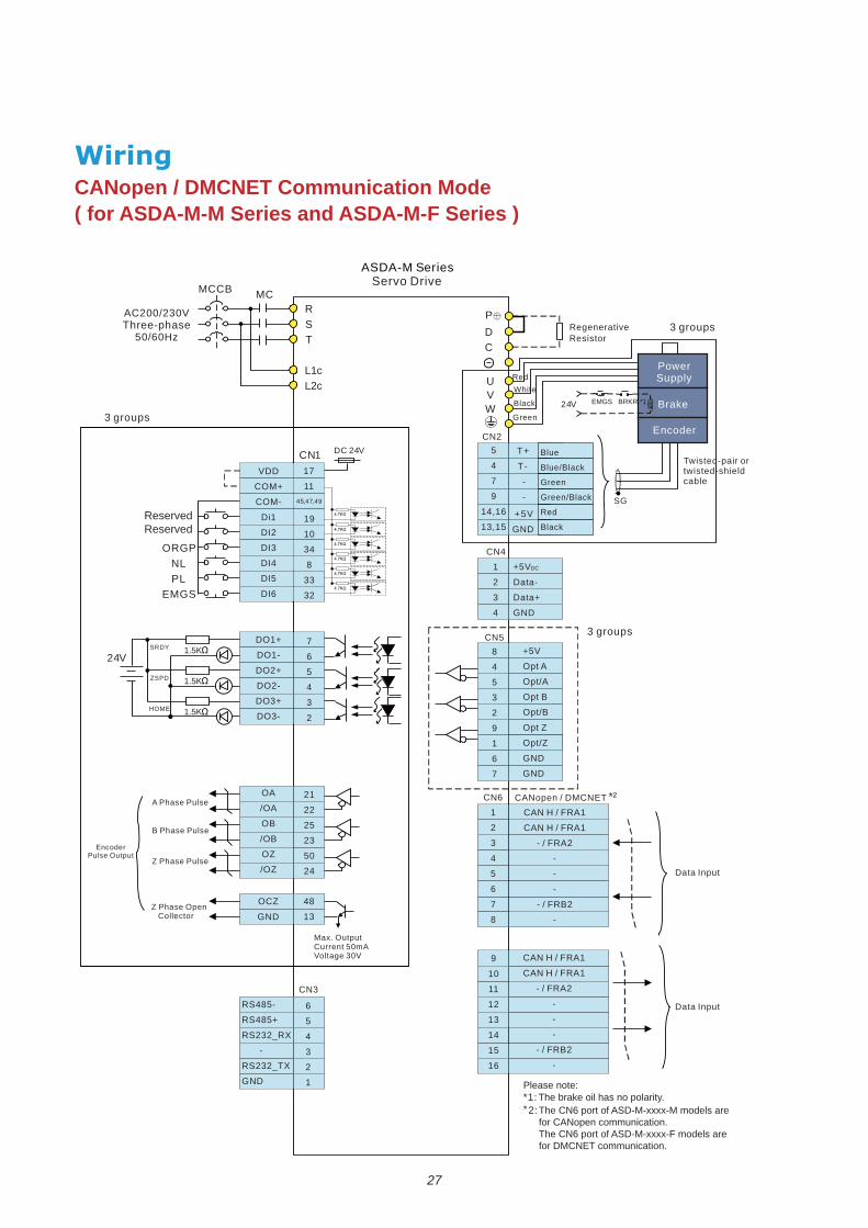
CANopen / DMCNET Communication Mode ( for ASDA-M-M Series and ASDA-M-F Series )
45,47,49
CN1
RST
L1cL2c
MCMCCB
PLEMGS
1.5K
1.5K
1.5K
SRDY
ZSPD
HOME
DC 24V
PDC
UVW
SG
24V
Data Input
ORGPNL
24V
3 groups
CN2
+5V
Data-
Data+
GND
CN4
1
2
3
4
3 groupsCN5+
Opt B
Opt/B
Opt Z
Opt/Z
GND
5V
Opt A
Opt/A
GND
8
4
5
3
2
9
1
6
7
CANopen / DMCNETCN61
2
3
4
5
6
7
8
CAN H / FRA1
CAN H / FRA1
- / FRA2
-
-
-
- / FRB2
-
CAN H / FRA1
CAN H / FRA1
- / FRA2
-
-
-
- / FRB2
-
9
10
11
12
13
14
15
16
48
13
OCZ
GND
3 groups
17
11
19
10
34
8
33
32
7
6
5
4
3
2
21
22
25
23
50
24
VDD
COM+
COM-
Di1
DI2
DI3
DI4
DI5
DI6
DO1+
DO1-
DO2+
DO2-
DO3+
DO3-
OA
/OA
OB
/OB
OZ
/OZ
RS485-
RS485+
RS232_RX
-
RS232_TX
GND
6
5
4
3
2
1
CN3
A Phase Pulse
Z Phase OpenCollector
EncoderPulse Output
B Phase Pulse
Z Phase Pulse
Max. OutputCurrent 50mAVoltage 30V
AC200/230V
50/60HzThree-phase Regenerative
Resistor
Twisted-pair ortwisted-shieldcable
T+
T-
-
+5V
-
GND
5
4
7
9
14,16
13,15
Blue
Blue/Black
Green
Green/Black
Black
Red
Green
RedWhite
Black
Data Input
EMGS BRKR *1
ReservedReserved
*²
DC
Brake
Power Supply
Encoder
**1:2:
The CN6 port of ASD-M-xxxx-M models arefor CANopen communication. The CN6 port of ASD-M-xxxx-F models arefor DMCNET communication.
The brake oil has no polarity.
ASDA-M SeriesServo Drive
Please note:

28
Servo Motor Features
ECMA Series servo motors are permanent AC servo motors. There are six kinds of frame sizes
for various applications.
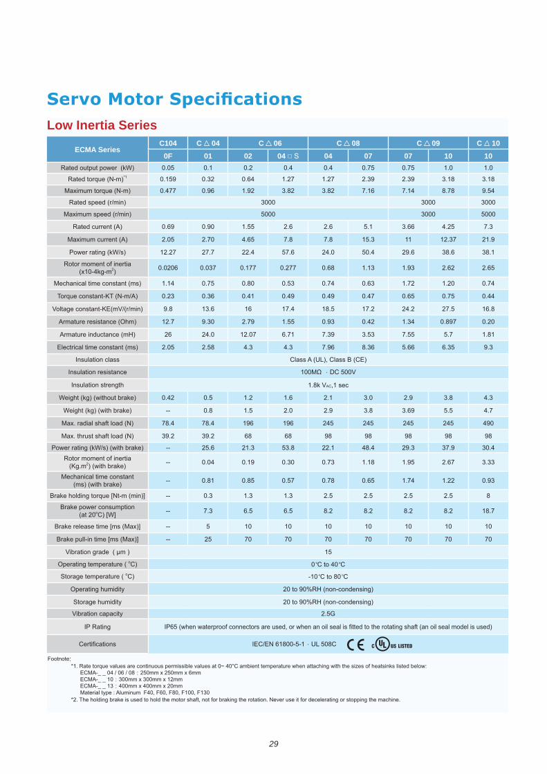
29
Low Inertia Series
ECMA SeriesC104 C 04 C 06 C 08 C 09 C 10
0F 01 02 04 S 04 07 07 10 10 0.1 0.2 1.0 1.0
*1 0.32 1.27 1.27 2.39 2.39
Maximum torque (N-m) 1.92
3000 3000 3000
Maximum speed (r/min) 3000
0.90 7.3
Maximum current (A) 2.70 11 12.37 21.9
12.27 27.7
2) 0.037 0.177 0.277 1.13 1.93
Mechanical time constant (ms) 1.72 1.20
Torque constant-KT (N-m/A) 0.23
17.2
Armature resistance (Ohm) 12.7 9.30 2.79 0.93 0.20
12.07 7.39
Electrical time constant (ms) 9.3
1.8k VAC,1 sec
Weight (kg) (without brake) 1.2 2.1 3.0 2.9
Weight (kg) (with brake) -- 2.0 2.9
Max. radial shaft load (N)
Max. thrust shaft load (N) 39.2 39.2
-- 21.3 22.1 29.3 37.9
(Kg.m2) (with brake) -- 0.19 0.30 0.73 3.33
Mechanical time constant (ms) (with brake) -- 1.22 0.93
-- 0.3 1.3 1.3
(at 20o -- 7.3
-- 10 10 10 10 10 10 10
-- 70 70 70 70 70 70 70
Operating temperature ( oC) 0 OC to 40 OC
Storage temperature ( oC) -10 OC to 80 OC
Operating humidity
Storage humidity
Footnote:
ECMA-_ _ 10 300mm x 300mm x 12mmECMA-_ _ 13
*2. The holding brake is used to hold the motor shaft, not for braking the rotation. Never use it for decelerating or stopping the machine.
30
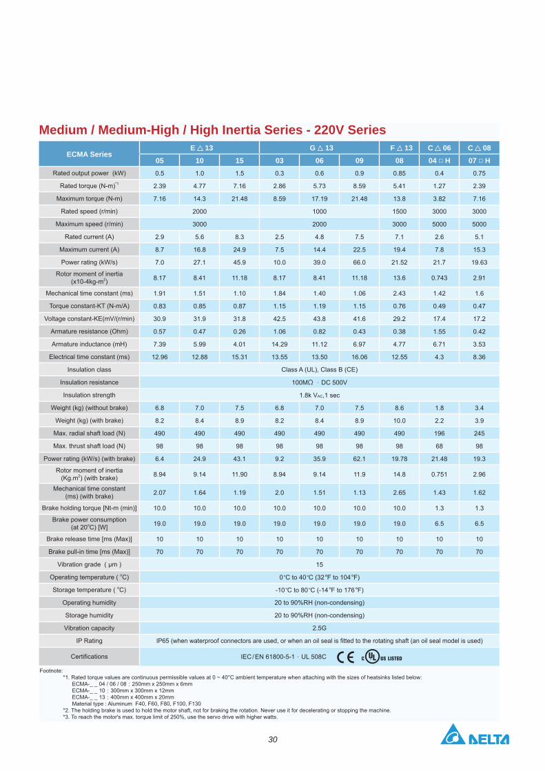
Medium / Medium-High / High Inertia Series - 220V Series
ECMA Series E 13 G 13 F 13 C 06 C 08
05 10 15 03 06 09 08 04 H 07 H0.5 1.0 1.5 0.3 0.6 0.9 0.85 0.4 0.75
*1 2.39 4.77 7.16 2.86 5.73 8.59 5.41 1.27 2.39
Maximum torque (N-m) 7.16 14.3 21.48 8.59 17.19 21.48 13.8 3.82 7.16
2000 1000 1500 3000 3000
Maximum speed (r/min) 3000 2000 3000 5000 5000
2.9 5.6 8.3 2.5 4.8 7.5 7.1 2.6 5.1
Maximum current (A) 8.7 16.8 24.9 7.5 14.4 22.5 19.4 7.8 15.3
7.0 27.1 45.9 10.0 39.0 66.0 21.52 21.7 19.63
2) 8.17 8.41 11.18 8.17 8.41 11.18 13.6 0.743 2.91
Mechanical time constant (ms) 1.91 1.51 1.10 1.84 1.40 1.06 2.43 1.42 1.6
Torque constant-KT (N-m/A) 0.83 0.85 0.87 1.15 1.19 1.15 0.76 0.49 0.47
30.9 31.9 31.8 42.5 43.8 41.6 29.2 17.4 17.2
Armature resistance (Ohm) 0.57 0.47 0.26 1.06 0.82 0.43 0.38 1.55 0.42
7.39 5.99 4.01 14.29 11.12 6.97 4.77 6.71 3.53
Electrical time constant (ms) 12.96 12.88 15.31 13.55 13.50 16.06 12.55 4.3 8.36
100M DC 500V
1.8k VAC,1 sec
Weight (kg) (without brake) 6.8 7.0 7.5 6.8 7.0 7.5 8.6 1.8 3.4
Weight (kg) (with brake) 8.2 8.4 8.9 8.2 8.4 8.9 10.0 2.2 3.9
Max. radial shaft load (N) 490 490 490 490 490 490 490 196 245
Max. thrust shaft load (N) 98 98 98 98 98 98 98 68 98
6.4 24.9 43.1 9.2 35.9 62.1 19.78 21.48 19.3
(Kg.m2) (with brake) 8.94 9.14 11.90 8.94 9.14 11.9 14.8 0.751 2.96
Mechanical time constant (ms) (with brake) 2.07 1.64 1.19 2.0 1.51 1.13 2.65 1.43 1.62
10.0 10.0 10.0 10.0 10.0 10.0 10.0 1.3 1.3
(at 20o 19.0 19.0 19.0 19.0 19.0 19.0 19.0 6.5 6.5
10 10 10 10 10 10 10 10 10
70 70 70 70 70 70 70 70 70
15
Operating temperature ( oC) 0 OC to 40 OC (32 OF to 104 OF)
Storage temperature ( oC) -10 OC to 80 OC (-14 OF to 176 OF)
Operating humidity
Storage humidity
IEC / EN 61800-5-1 UL 508C
Footnote:
ECMA-_ _ 10 300mm x 300mm x 12mmECMA-_ _ 13
*2. The holding brake is used to hold the motor shaft, not for braking the rotation. Never use it for decelerating or stopping the machine.
31
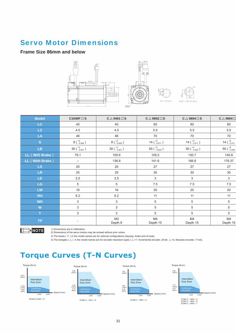
Frame Size 86mm and below
Servo Motor Dimensions
Model C1040F S C 0401 S C 0602 S C 0604 S C 0604
LC 40 40 60 60 60
LZ 4.5 4.5 5.5 5.5 5.5
LA 46 46 70 70 70
S 8 ( +0- 0.009 ) 8 ( +0
- 0.009 ) 14 ( +0- 0.011 ) 14 ( +0
- 0.011 ) 14 ( +0- 0.011 )
LB 30 ( +0- 0.021 ) 30 ( +0
- 0.021 ) 50 ( +0 ) 50 ( +0 ) 50 ( +0 )
LL W/O Brake 79.1 100.6 105.5 130.7 145.8
LL With Brake -- 136.8 141.6 166.8 176.37
LS 20 20 27 27 27
LR 25 25 30 30 30
LE 2.5 2.5 3 3 3
LG 5 5 7.5 7.5 7.5
LW 16 16 20 20 20
RH 6.2 6.2 11 11 11
WK 3 3 5 5 5
W 3 3 5 5 5
T 3 3 5 5 5
TP - M3Depth 8
M4Depth 15
M4Depth 15
M4Depth 15
ECMA-C 0602 S ECMA-C 0804 SECMA-C 0804 H ECMA-C 0804 7
ECMA-C 0401 S
Torque (N-m)
ECMA-C1040F S
1) Dimensions are in millimeters.2) Dimensions of the servo motors may be revised without prior notice.3) The boxes ( 4) The triangles ( ) in the model names are for encoder resolution types ( =1: Incremental encoder, 20-bit; =2: Absolute encoder, 17-bit).
Duty Zone Duty Zone Duty Zone Duty Zone
Torque (N-m)
Continuous Duty Zone
Continuous Duty Zone
Continuous Duty Zone
Continuous Duty Zone
Speed (r/min)Speed (r/min) Speed (r/min) Speed (r/min)
Torque (N-m) Torque (N-m)
32
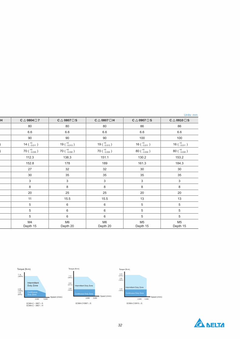
Units: mm
H C 0804 7 C 0807 S C 0807 H C 0907 S C 0910 S
80 80 80 86 86
6.6 6.6 6.6 6.6 6.6
90 90 90 100 100
) 14 ( +0- 0.011 ) 19 ( +0
- 0.013 ) 19 ( +0- 0.013 ) 16 ( +0
- 0.011 ) 16 ( +0- 0.011 )
) 70 ( +0- 0.030 ) 70 ( +0
- 0.030 ) 70 ( +0- 0.030 ) 80 ( +0
- 0.030 ) 80 ( +0- 0.030 )
112.3 138.3 151.1 130.2 153.2
152.8 178 189 161.3 184.3
27 32 32 30 30
30 35 35 35 35
3 3 3 3 3
8 8 8 8 8
20 25 25 20 20
11 15.5 15.5 13 13
5 6 6 5 5
5 6 6 5 5
5 6 6 5 5
M4Depth 15
M6Depth 20
M6Depth 20
M5Depth 15
M5Depth 15
ECMA-C 0807 SECMA-C 0807 H
Duty Zone
Continuous Duty Zone
Speed (r/min)
Torque (N-m)
ECMA-C10910 S
Torque (N-m)
7.14(298%)
2.38(100%)
6.00(251%)
Speed (r/min)
ECMA-C10907 S
Continuous Duty Zone
Intermittent Duty Zone
8.78(276%)
3.18(100%)
2,000 3,000
Torque (N-m)
Speed (r/min)
Continuous Duty Zone
Intermittent Duty Zone
5.85(184%)
33
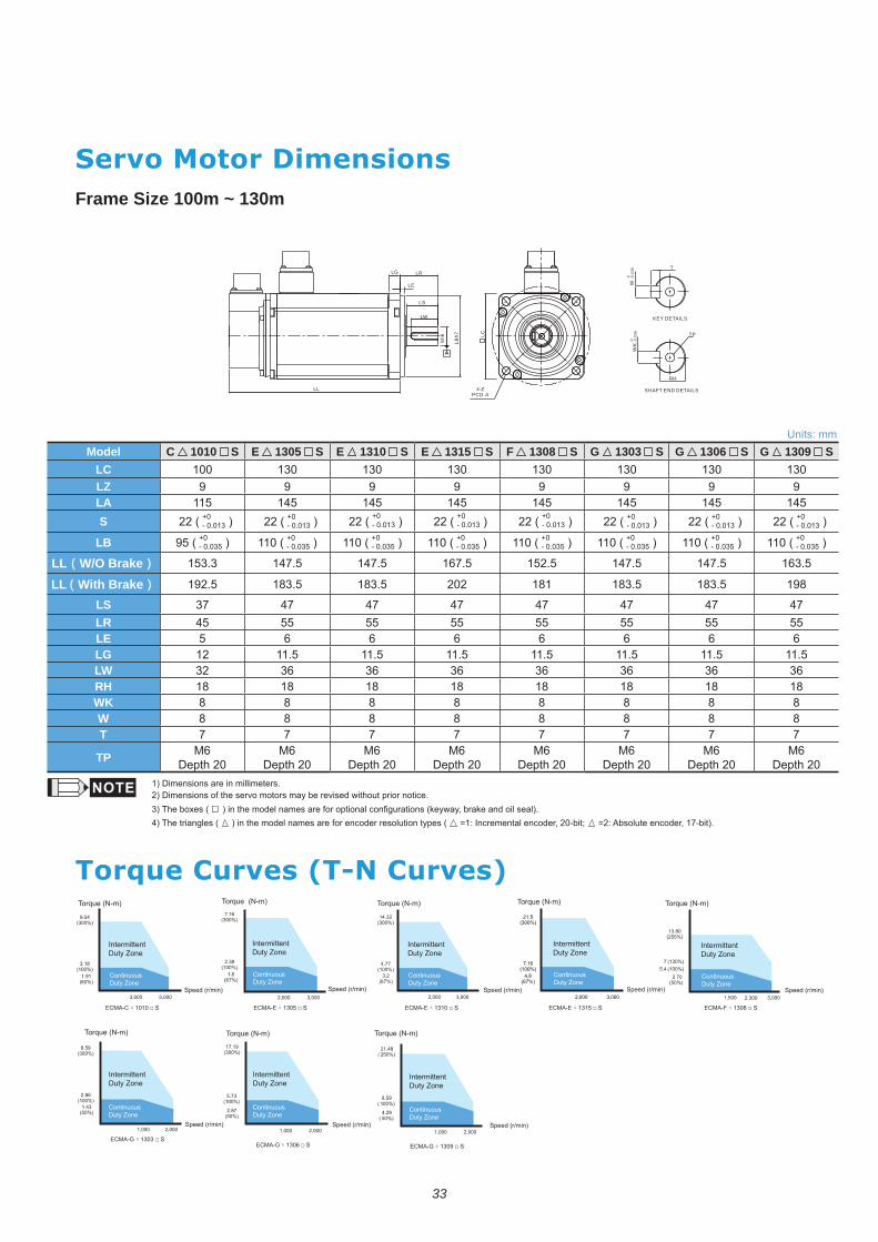
Frame Size 100m ~ 130m
LG LR
LE
LS
LW
LBh7
SHAFT END DETAILS
KEY DETAILS
Sh6
4-ZPCD-A
W -0
.036
0
-0.0
360
T
TP
RH
LC
LL
Units: mmModel C 1010 S E 1305 S E 1310 S E 1315 S F 1308 S G 1303 S G 1306 S G 1309 S
LC 100 130 130 130 130 130 130 130LZ 9 9 9 9 9 9 9 9LA 115 145 145 145 145 145 145 145S 22 ( +0
- 0.013 ) 22 ( +0- 0.013 ) 22 ( +0
- 0.013 ) 22 ( +0- 0.013 ) 22 ( +0
- 0.013 ) 22 ( +0- 0.013 ) 22 ( +0
- 0.013 ) 22 ( +0- 0.013 )
LB 95 ( +0 ) 110 ( +0 ) 110 ( +0 ) 110 ( +0 ) 110 ( +0 ) 110 ( +0 ) 110 ( +0 ) 110 ( +0 )
LL W/O Brake 153.3 147.5 147.5 167.5 152.5 147.5 147.5 163.5
LL With Brake 192.5 183.5 183.5 202 181 183.5 183.5 198
LS 37 47 47 47 47 47 47 47LR 45 55 55 55 55 55 55 55LE 5 6 6 6 6 6 6 6LG 12 11.5 11.5 11.5 11.5 11.5 11.5 11.5LW 32 36 36 36 36 36 36 36RH 18 18 18 18 18 18 18 18WK 8 8 8 8 8 8 8 8W 8 8 8 8 8 8 8 8T 7 7 7 7 7 7 7 7
TP M6Depth 20
M6Depth 20
M6Depth 20
M6Depth 20
M6Depth 20
M6Depth 20
M6Depth 20
M6Depth 20
1) Dimensions are in millimeters.2) Dimensions of the servo motors may be revised without prior notice.3) The boxes ( 4) The triangles ( ) in the model names are for encoder resolution types ( =1: Incremental encoder, 20-bit; =2: Absolute encoder, 17-bit).
ECMA-C 1010 S
ECMA-G 1306 S ECMA-G 1309 S
ECMA-E 1310 S ECMA-F 1308 S
2,300
ECMA-G 1303 S
ECMA-E 1305 S ECMA-E 1315 S
Torque (N-m)
Duty Zone
Continuous Duty Zone
Speed (r/min)
Torque (N-m) Torque (N-m) Torque (N-m) Torque (N-m)
Torque (N-m) Torque (N-m) Torque (N-m)
Duty Zone Duty Zone Duty Zone Duty Zone
Duty ZoneDuty ZoneDuty Zone
Continuous Duty Zone
Continuous Duty Zone
Continuous Duty Zone
Continuous Duty Zone
Continuous Duty Zone
Continuous Duty Zone
Continuous Duty Zone
Speed (r/min) Speed (r/min) Speed (r/min) Speed (r/min)
Speed (r/min)Speed (r/min)Speed (r/min)
34
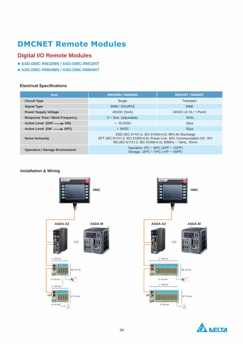
Digital I/O Remote ModulesASD-DMC-RM32MN / ASD-DMC-RM32NTASD-DMC-RM64MN / ASD-DMC-RM64NT
Installation & Wiring
Item RM32MN / RM64MN RM32NT / RM64NT
Circuit Type Single Transistor
Signal Type SINK / SOURCE SINK
Power Supply Voltage 24VDC (5mA) 24VDC (0.1A / 1 Point)
Response Time / Work Frequency 0 ~ 3ms (adjustable) 1KHz
Active Level (OFF ON) 16.5VDC 20μs
Active Level (ON OFF) 8VDC 30μs
Noise ImmunityESD (IEC 61131-2, IEC 61000-4-2): 8KV Air Discharge
EFT (IEC 61131-2, IEC 61000-4-4): Power Line: 2KV, Communication I/O: 1KV RS (IEC 61131-2, IEC 61000-4-3): 80MHz ~ 1GHz, 10V/m
Operation / Storage Environment Operation: 0ºC ~ 50ºC (32ºF ~ 122ºF)Storage: -20ºC ~ 70ºC (-4ºF ~ 158ºF)
OR OR
W W
HMC HMC
ASDA-M ASDA-MASDA-A2 ASDA-A2
35
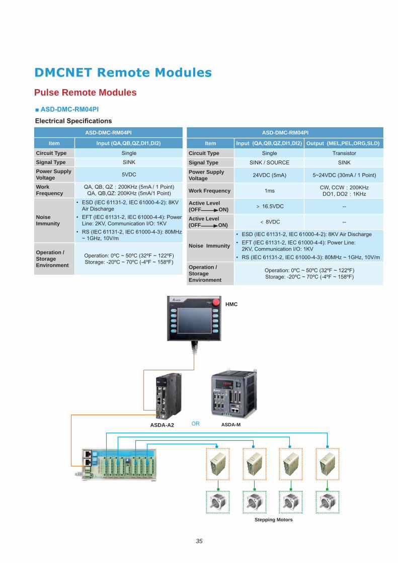
ASD-DMC-RM04PI
Item
Circuit Type Single
Signal TypePower Supply VoltageWork Frequency
Noise Immunity
• Air Discharge
•
•
Operation / Storage Environment
ASD-DMC-RM04PI
Item Output (MEL,PEL,ORG,SLD)
Circuit Type Single Transistor
Signal Type
Power Supply Voltage
Work Frequency 1ms CW, CCWDO1, DO2
Active Level (OFF ON) --
Active Level (OFF ON) --
Noise Immunity
• •
•
Operation / Storage Environment
OR
HMC
ASDA-M
Stepping Motors
ASDA-A2
Pulse Remote Modules

36
ASD-DMC-RM04DA
Item Analog to Digital - Input Point (RM04AD)
Analog Output Channel
Range of Analog Voltage Output
Range of Analog Current Output
Over Range of Analog Output 10%
Max. Output Current 20mA
Allowable Load Impedance
Range of Digital Data
Resolution
DC Output Impedance
Response Time 1ms
Digital Data Format
Isolation isolated by optical coupler.
Protection damage to internal circuits. Current output can be open circuit.
Noise Immunity
• Discharge
•
• •
Operation / Storage Environment
ASD-DMC-RM04AD
Item Analog to Digital - Input Point (RM04AD)
Analog Output Channel
Range of Analog Voltage Output
Range of Analog Current Output
Range of Digital Data
Resolution
Voltage Input Impedance
Current Input Impedance
Overall Accuracy
Response Time Min. 1ms. Max. 3ms × the number of channels
Isolation isolated by optical coupler.
Range of Absolute Voltage Input
Range of Absolute Current Input 32mA
Digital Data Format
Noise Immunity
• Discharge
•
• •
Operation / Storage Environment
HMCHMC
ASDA-MASDA-M
ASDA-A2ASDA-A2
OROR
Analog I/O Remote Modules
37
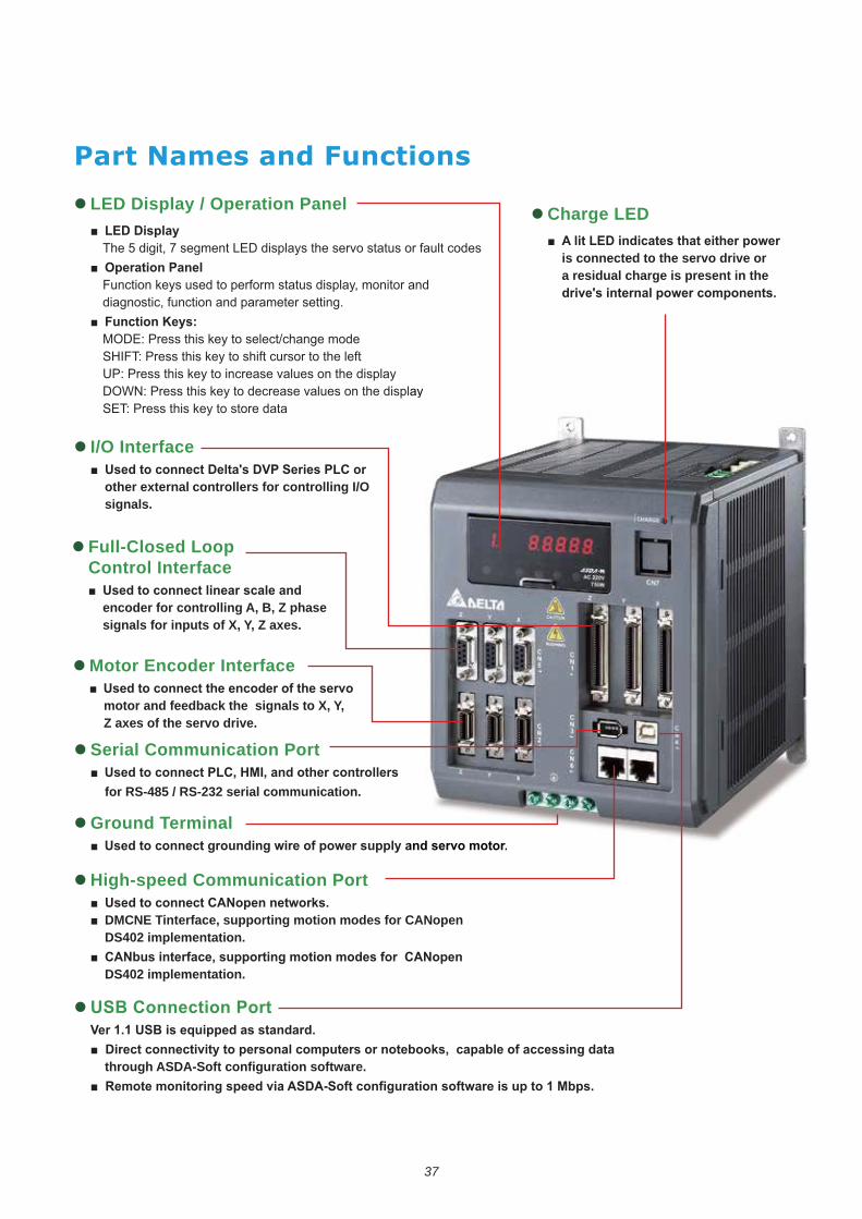
LED Display / Operation Panel
Function keys used to perform status display, monitor and diagnostic, function and parameter setting.
I/O Interface
other external controllers for controlling I/O signals.
Charge LED
is connected to the servo drive or a residual charge is present in the
Full-Closed Loop Control Interface
encoder for controlling A, B, Z phase signals for inputs of X, Y, Z axes.
Motor Encoder Interface
motor and feedback the signals to X, Y, Z axes of the servo drive.
Serial Communication Port
for RS-485 / RS-232 serial communication.
High-speed Communication Port
DMCNE Tinterface, supporting motion modes for CANopen DS402 implementation.
DS402 implementation.
Ground Terminal
through ASDA-Soft configuration software.
38
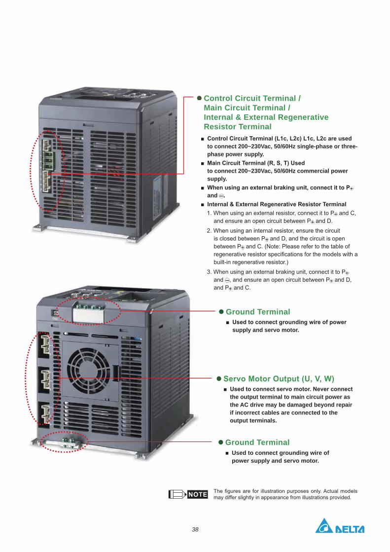
Control Circuit Terminal / Main Circuit Terminal / Internal & External Regenerative Resistor Terminal
Ground Terminal
supply and servo motor.
the output terminal to main circuit power as the AC drive may be damaged beyond repair if incorrect cables are connected to the output terminals.
Ground TerminalUsed to connect grounding wire of power supply and servo motor.
to connect 200~230Vac, 50/60Hz single-phase or three-phase power supply.
to connect 200~230Vac, 50/60Hz commercial power supply.
and .
and C, and D.
2. When using an internal resistor, ensure the circuit and D, and the circuit is open
regenerative resistor specifications for the models with a built-in regenerative resistor.)
and and D,
and C.
may differ slightly in appearance from illustrations provided.
39
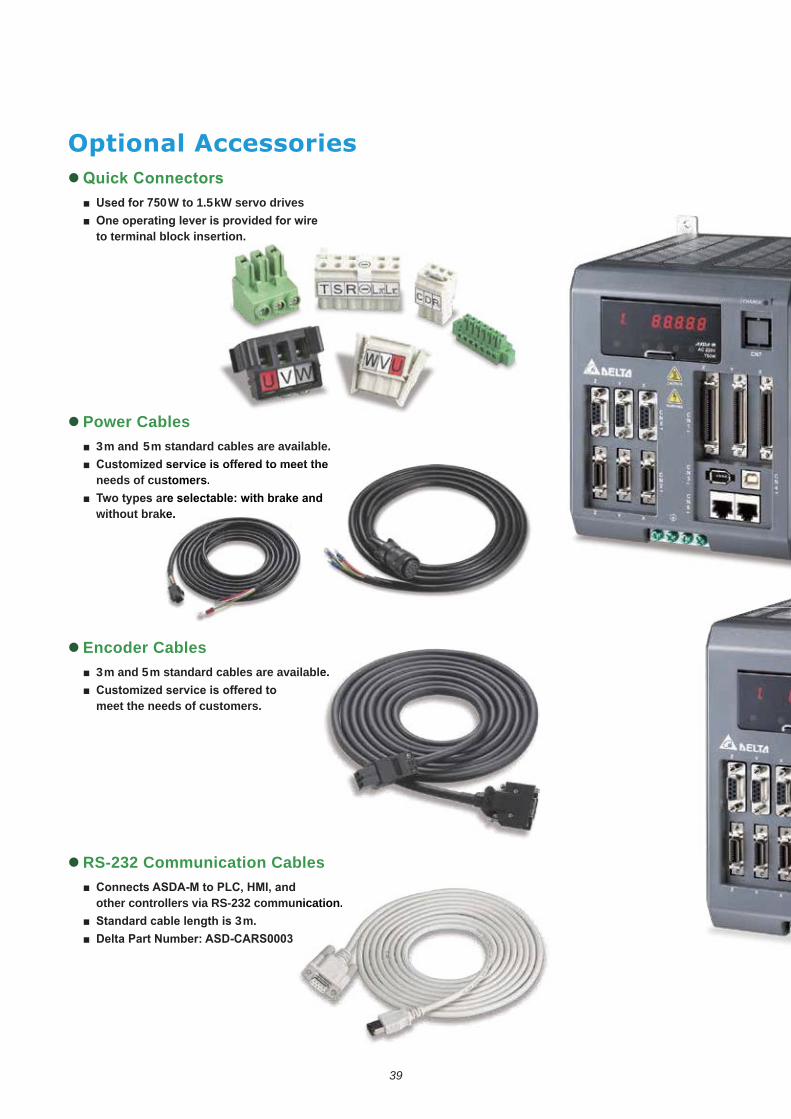
0W to 1.5kW servo drives
to terminal block insertion.
Power Cables3m and 5m standard cables are available.
needs of customers.
without brake.
Encoder Cables3m and 5m standard cables are available.
meet the needs of customers.
RS-232 Communication Cables
other controllers via RS-232 communication.3m.
stomers.
ke.
e.
nication.
40
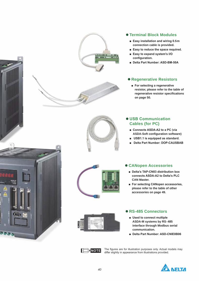
Terminal Block Modules5m
connection cable is provided.
configuration.
Regenerative Resistors
resistor, please refer to the table of regenerative resistor specifications on page 50.
Cables (for PC)
ASDA-Soft configuration software)
CANopen Accessories
CAN Master.
please refer to the table of other accessories on page 49.
RS-485 Connectors
ASDA-M systems by RS-485 interface through Modbus serial communication.
differ slightly in appearance from illustrations provided.

41
Optional Cables and Connectors Power Connectors
Power Cables
ASDBCAPW0000
ASD-ABPW0003, ASD-ABPW0005
ASDBCAPW0100 ASD-CAPW1000
Item Part No.L
mm inch
1 ASD-ABPW0003 3000 100 118 4
2 ASD-ABPW0005 5000 100 197 4
Item Part No.L
mm inch
1 ASD-ABPW0103 3000 100 118 4
2 ASD-ABPW0105 5000 100 197 4
3106A-20-18S
L
L
ASD-ABPW0103, ASD-ABPW0105
42
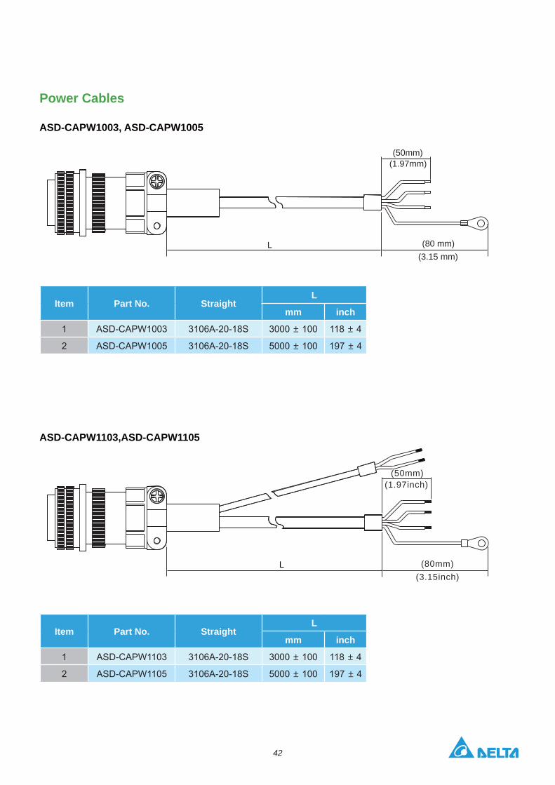
Power Cables
(80 mm)(3.15 mm)
(50mm)(1.97mm)
L
(3.15inch)(80mm)
(1.97inch)(50mm)
L
ASD-CAPW1003, ASD-CAPW1005
ASD-CAPW1103,ASD-CAPW1105
Item Part No. StraightL
mm inch
1 ASD-CAPW1003 3106A-20-18S 3000 100 118 4
2 ASD-CAPW1005 3106A-20-18S 5000 100 197 4
Item Part No. StraightL
mm inch
1 ASD-CAPW1103 3106A-20-18S 3000 100 118 4
2 ASD-CAPW1105 3106A-20-18S 5000 100 197 4
43
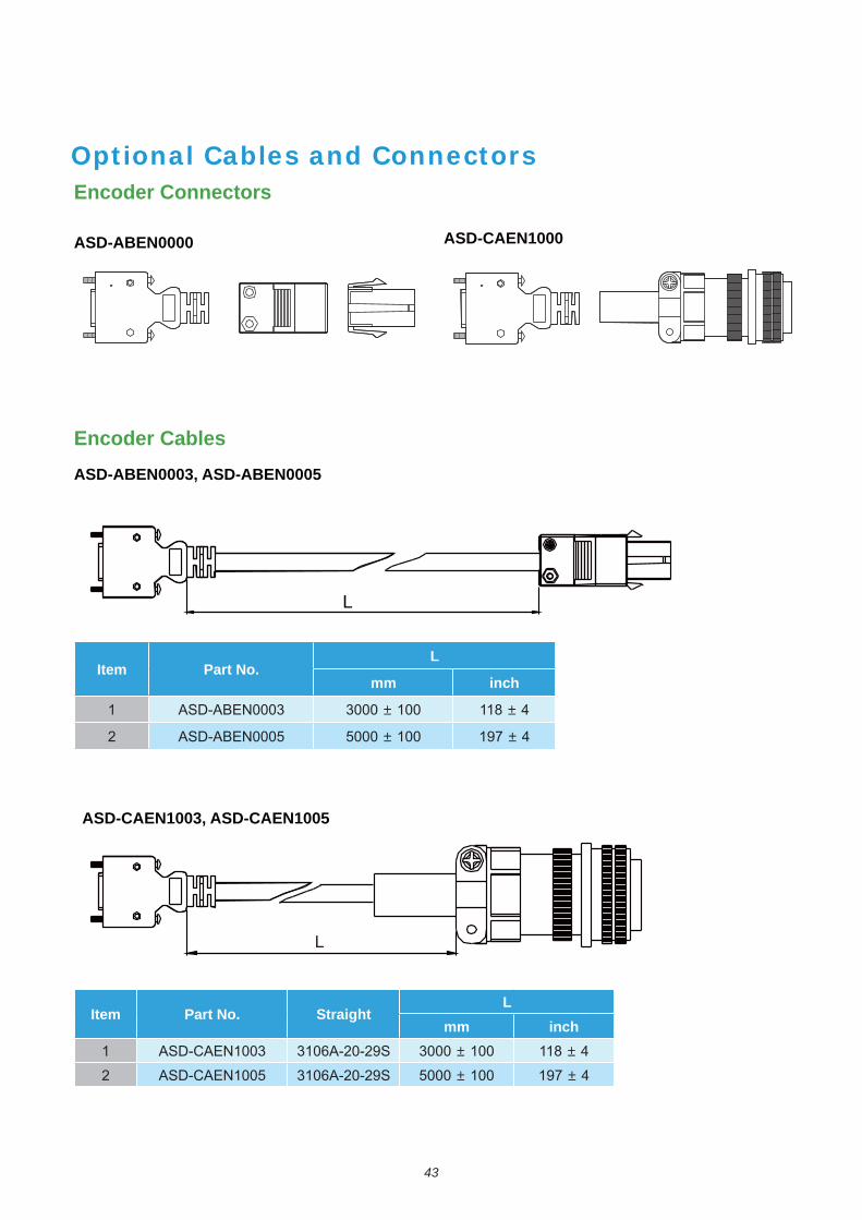
Optional Cables and Connectors
Encoder CablesASD-ABEN0003, ASD-ABEN0005
ASD-CAEN1003, ASD-CAEN1005
Item Part No. StraightL
mm inch1 ASD-CAEN1003 3106A-20-29S 3000 100 118 4
2 ASD-CAEN1005 3106A-20-29S 5000 100 197 4
L
L
Encoder Connectors
ASD-ABEN0000 ASD-CAEN1000
Item Part No.L
mm inch
1 ASD-ABEN0003 3000 100 118 4
2 ASD-ABEN0005 5000 100 197 4
44
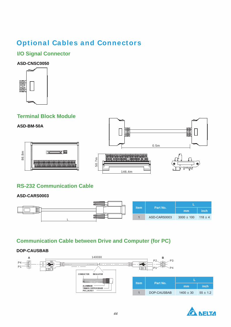
Optional Cables and Connectors I/O Signal Connector
ASD-CNSC0050
Terminal Block Module
ASD-BM-50A
RS-232 Communication Cable
ASD-CARS0003
Communication Cable between Drive and Computer (for PC)
DOP-CAUSBAB
L
146.4 mm
50.7
mm
86.8
mm
0.5m
86.8
m
50.7
m
146.4m
P4P1
120.5 120.5
140030A BP2
P1
P3
P4
CONDUCTOR INSULATOR
ALUMINUMTINNED COPPER BRAIDPVC JACKET
Item Part No.L
mm inch
1 ASD-CARS0003 3000 100 118 4
Item Part No.L
mm inch
1 DOP-CAUSBAB 1400 30 55 1.2
45
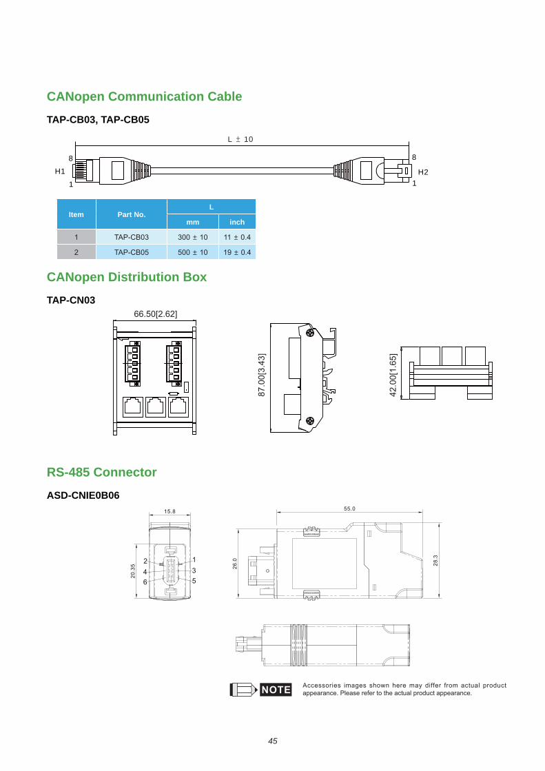
66.50[2.62]
87.0
0[3.
43]
42.0
0[1.
65]
H1
1
8
L 10
8
1H2
CANopen Communication Cable
TAP-CB03, TAP-CB05
CANopen Distribution Box
TAP-CN03
RS-485 Connector
ASD-CNIE0B06
Item Part No.L
mm inch
1 TAP-CB03 300 10 11 0.4
2 TAP-CB05 500 10 19 0.4
Accessories images shown here may differ from actual product appearance. Please refer to the actual product appearance.
46
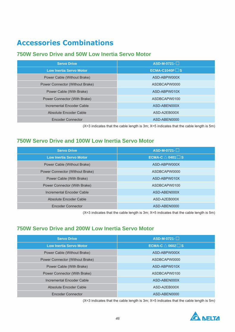
750W Servo Drive and 100W Low Inertia Servo Motor
750W Servo Drive and 50W Low Inertia Servo Motor
750W Servo Drive and 200W Low Inertia Servo Motor
Servo Drive ASD-M-0721-
Low Inertia Servo Motor ECMA-C 0401 S
Power Cable (Without Brake) ASD-ABPW000X
Power Connector (Without Brake) ASDBCAPW0000
Power Cable (With Brake) ASD-ABPW010X
Power Connector (With Brake) ASDBCAPW0100
Incremental Encoder Cable ASD-ABEN000X
Absolute Encoder Cable ASD-A2EB000X
Encoder Connector ASD-ABEN0000
(X=3 indicates that the cable length is 3m; X=5 indicates that the cable length is 5m)
Servo Drive ASD-M-0721-
Low Inertia Servo Motor ECMA-C 0602 S
Power Cable (Without Brake) ASD-ABPW000X
Power Connector (Without Brake) ASDBCAPW0000
Power Cable (With Brake) ASD-ABPW010X
Power Connector (With Brake) ASDBCAPW0100
Incremental Encoder Cable ASD-ABEN000X
Absolute Encoder Cable ASD-A2EB000X
Encoder Connector ASD-ABEN0000
(X=3 indicates that the cable length is 3m; X=5 indicates that the cable length is 5m)
Servo Drive ASD-M-0721-
Low Inertia Servo Motor ECMA-C1040F S
Power Cable (Without Brake) ASD-ABPW000X
Power Connector (Without Brake) ASDBCAPW0000
Power Cable (With Brake) ASD-ABPW010X
Power Connector (With Brake) ASDBCAPW0100
Incremental Encoder Cable ASD-ABEN000X
Absolute Encoder Cable ASD-A2EB000X
Encoder Connector ASD-ABEN0000
(X=3 indicates that the cable length is 3m; X=5 indicates that the cable length is 5m)

47
750W Servo Drive and 500W Medium Inertia Servo Motor
750W Servo Drive and 300W High Inertia Servo Motor
750W Servo Drive and 400W Low Inertia Servo Motor Servo Drive ASD-M-0721-
Low Inertia Servo MotorECMA-C 0604 SECMA-C 0604 HECMA-C 0804 7
Power Cable (Without Brake) ASD-ABPW000X
Power Connector (Without Brake) ASDBCAPW0000
Power Cable (With Brake) ASD-ABPW010X
Power Connector (With Brake) ASDBCAPW0100
Incremental Encoder Cable ASD-ABEN000X
Absolute Encoder Cable ASD-A2EB000X
Encoder Connector ASD-ABEN0000
(X=3 indicates that the cable length is 3m; X=5 indicates that the cable length is 5m)
Servo Drive ASD-M-0721-
Medium Inertia Servo Motor ECMA-E 1305 S
Power Cable (Without Brake) ASD-CAPW100X
Power Cable (With Brake) ASD-CAPW110X
Power Connector ASD-CAPW1000
Power Connector (With Brake) ASD-CAEN100X
Incremental Encoder Cable ASD-CAEN100X
Absolute Encoder Cable ASD-A2EB100X
Encoder Connector ASD-CAEN1000
(X=3 indicates that the cable length is 3m; X=5 indicates that the cable length is 5m)
Servo Drive ASD-M-0721-
High Inertia Servo Motor ECMA-G 1303 S
Power Cable (Without Brake) ASD-CAPW100X
Power Connector (Without Brake) ASD-CAPW110X
Power Cable (With Brake) ASD-CAPW1000
Power Connector (With Brake) ASD-CAEN100X
Incremental Encoder Cable ASD-A2EB100X
Absolute Encoder Cable ASD-CAEN1000
Encoder Connector ASD-CAEN1000
(X=3 indicates that the cable length is 3m; X=5 indicates that the cable length is 5m)

48
750kW Servo Drive and 600kW High Inertia Servo Motor
1.5kW Servo Drive and 850W High Inertia Servo Motor
750W Servo Drive and 750W Low Inertia Servo Motor
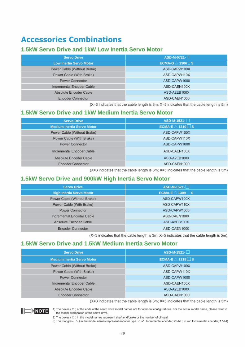
1.5kW Servo Drive and 1kW Low Inertia Servo Motor
Servo Drive ASD-M-1521-Medium Inertia Servo Motor ECMA-F 1308 SPower Cable (Without Brake) ASD-CAPW100X
Power Cable (With Brake) ASD-CAPW110X
Power Connector ASD-CAPW1000
Incremental Encoder Cable ASD-CAEN100X
Absolute Encoder Cable ASD-A2EB100X
Encoder Connector ASD-CAEN1000
(X=3 indicates that the cable length is 3m; X=5 indicates that the cable length is 5m)
Servo Drive ASD-M-1521-High Inertia Servo Motor ECMA-C 1010 S
Power Cable (Without Brake) ASD-CAPW100X
Power Cable (With Brake) ASD-CAPW110X
Power Connector ASD-CAPW1000
Incremental Encoder Cable ASD-CAEN100X
Absolute Encoder Cable ASD-A2EB100X
Encoder Connector ASD-CAEN1000
(X=3 indicates that the cable length is 3m; X=5 indicates that the cable length is 5m)
Servo Drive ASD-M-0721-
Low Inertia Servo MotorECMA-C 0807 SECMA-C 0807 HECMA-C 0907 S
Power Cable (Without Brake) ASD-ABPW000X
Power Connector (Without Brake) ASDBCAPW0000
Power Cable (With Brake) ASD-ABPW010X
Power Connector (With Brake) ASDBCAPW0100
Incremental Encoder Cable ASD-ABEN000X
Absolute Encoder Cable ASD-A2EB000X
Encoder Connector ASD-ABEN0000
(X=3 indicates that the cable length is 3m; X=5 indicates that the cable length is 5m)
Servo Drive ASD-M-1521-Low Inertia Servo Motor ECMA-C 0910 S
Power Cable (Without Brake) ASD-ABPW000X
Power Connector (Without Brake) ASDBCAPW0000
Power Cable (With Brake) ASD-ABPW010X
Power Connector (With Brake) ASDBCAPW0100
Incremental Encoder Cable ASD-ABEN000X
Absolute Encoder Cable ASD-A2EB000X
Encoder Connector ASD-ABEN0000
(X=3 indicates that the cable length is 3m; X=5 indicates that the cable length is 5m)
49
1.5kW Servo Drive and 900kW High Inertia Servo Motor
1.5kW Servo Drive and 1kW Medium Inertia Servo Motor
1.5kW Servo Drive and 1.5kW Medium Inertia Servo Motor
Servo Drive ASD-M-1521-High Inertia Servo Motor ECMA-E 1309 S
Power Cable (Without Brake) ASD-CAPW100X
Power Cable (With Brake) ASD-CAPW110X
Power Connector ASD-CAPW1000
Incremental Encoder Cable ASD-CAEN100X
Absolute Encoder Cable ASD-A2EB100X
Encoder Connector ASD-CAEN1000
(X=3 indicates that the cable length is 3m; X=5 indicates that the cable length is 5m)
Servo Drive ASD-M-1521-
Medium Inertia Servo Motor ECMA-E 1315 S
Power Cable (Without Brake) ASD-CAPW100X
Power Cable (With Brake) ASD-CAPW110X
Power Connector ASD-CAPW1000
Incremental Encoder Cable ASD-CAEN100X
Absolute Encoder Cable ASD-A2EB100X
Encoder Connector ASD-CAEN1000
(X=3 indicates that the cable length is 3m; X=5 indicates that the cable length is 5m)
Servo Drive ASD-M-1521-Medium Inertia Servo Motor ECMA-E 1310 SPower Cable (Without Brake) ASD-CAPW100X
Power Cable (With Brake) ASD-CAPW110X
Power Connector ASD-CAPW1000
Incremental Encoder Cable ASD-CAEN100X
Absolute Encoder Cable ASD-A2EB100X
Encoder Connector ASD-CAEN1000
(X=3 indicates that the cable length is 3m; X=5 indicates that the cable length is 5m)
1) The boxes ( the model explanation of the servo drive.
2) The boxes ( ) in the model names represent shaft end/brake or the number of oil seal.3) The triangles ( ) in the model names represent encoder type.
1.5kW Servo Drive and 1kW Low Inertia Servo Motor Servo Drive ASD-M-0721-
Low Inertia Servo Motor ECMA-G 1306 SPower Cable (Without Brake) ASD-CAPW100X
Power Cable (With Brake) ASD-CAPW110X
Power Connector ASD-CAPW1000
Incremental Encoder Cable ASD-CAEN100X
Absolute Encoder Cable ASD-A2EB100X
Encoder Connector ASD-CAEN1000
(X=3 indicates that the cable length is 3m; X=5 indicates that the cable length is 5m)
50
Safety Information
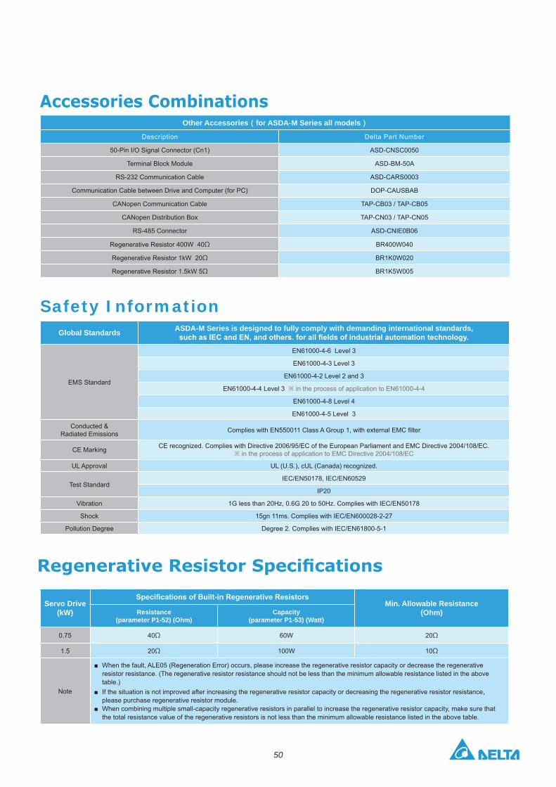
Other Accessories for ASDA-M Series all models
Description
CANopen Communication Cable
Regenerative Resistor 400W 40 BR400W040
Regenerative Resistor 1kW 20 BR1K0W020
Regenerative Resistor 1.5kW 5 BR1K5W005
Global Standards ASDA-M Series is designed to fully comply with demanding international standards,
EMS Standard
EN61000-4-6 Level 3
EN61000-4-3 Level 3
EN61000-4-2 Level 2 and 3
EN61000-4-4 Level 3 in the process of application to EN61000-4-4
EN61000-4-8 Level 4
EN61000-4-5 Level 3
Conducted & Radiated Emissions
CE Marking CE recognized. Complies with Directive 2006/95/EC of the European Parliament and EMC Directive 2004/108/EC. in the process of application to EMC Directive 2004/108/EC
UL Approval UL (U.S.), cUL (Canada) recognized.
Test StandardIEC/EN50178, IEC/EN60529
IP20
Vibration 1G less than 20Hz, 0.6G 20 to 50Hz. Complies with IEC/EN50178
Shock 15gn 11ms. Complies with IEC/EN600028-2-27
Pollution Degree Degree 2. Complies with IEC/EN61800-5-1
Servo Drive (kW)
Min. Allowable Resistance (Ohm)Resistance
(parameter P1-52) (Ohm)Capacity
(parameter P1-53) (Watt)
0.75 40 60W 20
1.5 20 100W 10
Note
resistor resistance. (The regenerative resistor resistance should not be less than the minimum allowable resistance listed in the above table.)
please purchase regenerative resistor module.
When combining multiple small-capacity regenerative resistors in parallel to increase the regenerative resistor capacity, make sure that the total resistance value of the regenerative resistors is not less than the minimum allowable resistance listed in the above table.

DELTA_IA-ASDA_ASDA-M_C_EN_20170317
Industrial Automation HeadquartersDelta Electronics, Inc. Taoyuan Technology CenterNo.18, Xinglong Rd., Taoyuan City, Taoyuan County 33068, TaiwanTEL: 886-3-362-6301 / FAX: 886-3-371-6301
AsiaDelta Electronics (Jiangsu) Ltd.Wujiang Plant 31688 Jiangxing East Road, Wujiang Economic Development ZoneWujiang City, Jiang Su Province, People's Republic of China (Post code: 215200)TEL: 86-512-6340-3008 / FAX: 86-769-6340-7290
Delta Greentech (China) Co., Ltd.238 Min-Xia Road, Pudong District, ShangHai, P.R.C.Post code : 201209TEL: 86-21-58635678 / FAX: 86-21-58630003 Delta Electronics (Japan), Inc.
2-1-14 Minato-ku Shibadaimon, Tokyo 105-0012, JapanTEL: 81-3-5733-1111 / FAX: 81-3-5733-1211
Delta Electronics (Korea), Inc.1511, Byucksan Digital Valley 6-cha, Gasan-dong, Geumcheon-gu, Seoul, Korea, 153-704TEL: 82-2-515-5303 / FAX: 82-2-515-5302
Delta Electronics Int’l (S) Pte Ltd4 Kaki Bukit Ave 1, #05-05, Singapore 417939TEL: 65-6747-5155 / FAX: 65-6744-9228
Delta Electronics (India) Pvt. Ltd.Plot No 43 Sector 35, HSIIDC Gurgaon, PIN 122001, Haryana, India TEL : 91-124-4874900 / FAX : 91-124-4874945
AmericasDelta Products Corporation (USA)
P.O. Box 12173,5101 Davis Drive, Research Triangle Park, NC 27709, U.S.A.TEL: 1-919-767-3800 / FAX: 1-919-767-8080
Delta Greentech (Brasil) S.A
01332-000-São Paulo-SP-BrazilTEL: +55 11 3568-3855 / FAX: +55 11 3568-3865
EuropeDelta Electronics (Netherlands) B.V.
De Witbogt 20, 5652 AG Eindhoven, The Netherlands TEL: +31 (0)40-8003800 / FAX: +31 (0)40-8003898
*We reserve the right to change the information in this catalogue without prior notice.