Embed Size (px)
Citation preview
1 - 8 0 0 - 6 3 3 - 0 4 0 515–24 Drives/Motors/Motion
AC Servo Drive Specifications
SureServo systems run "out-of-the-box"… but may be reconfigured for many applications!The SureServo drives are fully digital and include over 165programmable parameters. For convenience, the parameters aregrouped into five categories:
1) Monitor parameters2) Basic parameters3) Extended parameters4) Communication parameters5) Diagnostic parameters.
All parameters have commonly used default values which allowyou to operate the SureServo system "out-of-the-box". However,the programmability and large variety of parameters make theSureServo systems suitable for a very broad range of applications,including almost all types of general purpose industrial machinerysuch as assembly, test, packaging, machine tool, and robotics.
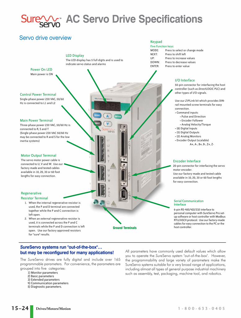
Power On LEDMain power is ON
LED DisplayThe LED display has 5 full digits and is used toindicate servo status and alarms
Ground Terminals
Serial CommunicationInterface6-pin RS-485/422/232 interface topersonal computer with SureServo Pro set-up software or host controller with ModbusRTU/ASCII protocol. Use our factory-madecables for easy connection to the PC or thehost controller.
I/O Interface50-pin connector for interfacing the hostcontroller (such as DirectLOGIC PLC) andother types of I/O signals.
Use our ZIPLink kit which provides DIN-rail mounted screw terminals for easyconnection.• Command inputs :
• Pulse and Direction• Encoder Follower• Analog Velocity/Torque
• (8) Digital Inputs• (5) Digital Outputs• (2) Analog Monitors• Encoder Output (scalable)
A+, A-, B+, B-, Z+, Z-
KeypadFive Function keys:MODE: Press to select or change modeNEXT: Press to shift leftUP: Press to increase valuesDOWN: Press to decrease valuesENTER: Press to enter value
Encoder Interface20-pin connector for interfacing the servomotor encoder. Use our factory-made and tested cableavailable in 10, 20, 30 or 60 foot lengthsfor easy connection.
Control Power TerminalSingle-phase power 230 VAC, 50/60Hz is connected to L1 and L2
Main Power TerminalThree-phase power 230 VAC, 50/60 Hz isconnected to R, S and T(Single-phase power 230 VAC 50/60 Hzmay be connected to R and S for the lowinertia systems)
Motor Output TerminalThe servo motor power cable isconnected to U, V and W. Use ourfactory made and tested cablesavailable in 10, 20, 30 or 60 footlengths for easy connection.
RegenerativeResistor Terminal
1. When the internal regenerative resistor isused, the P and D terminal are connectedtogether while the P and C connection is left open.
2. When an external regenerative resistor isused, it is connected across the P and Cterminals while the P and D connection is leftopen. Use our factory approved resistorsfor "sure" results.
Servo drive overview
2007_tsureservo_unpriced:2007_tsureservo_priced.qxd 9/10/2007 4:24 PM Page 15–24
AC Servo Drive Specifications
Servo drive specificationsGeneral Drive Specifications
Permissible Frequency 50/60 Hz ±5%
Encoder Resolution / Feedback Resolution 2500 lines / 10000 ppr
Control of Main Circuit SVPWM (Space Vector Pulse Width Modulation) Control
Tuning Modes Easy / Auto / Manual
Dynamic Brake Built-in control
Analog Monitor Outputs (2) Monitor signal can be set by parameters (Output voltage range: ±8V)
8 Programmable Digital Inputs(45 selectable functions)
Servo enable, Alarm reset, Gain switching, Pulse counter clear, Fault stop, CW/CCW over-travel
Internal parameter selection, Torque limit activation, Velocity limit activation, Control mode selection
Scalable Encoder Output Encoder signal output A, /A, B, /B, Z /Z, Line Driver
5 Programmable Outputs(9 selectable indicators)
Servo ready, Servo On, Low velocity, Velocity reached, In Position, Torque limiting, Servo fault, Electromagnetic brake control, Home search completed
Communication Interface RS-232 / RS-485 / RS-422 / Modbus ASCII & RTU up to 115k Baud
Protective Functions Overcurrent, Overvoltage, Undervoltage, Overload, Excessive velocity/position error, Encoder error, Regeneration error, Communication error
Installation Site Indoor location (free from direct sunlight), no corrosive liquid and gas (far away from oil mist, flammable gas, dust)
Altitude 1000m above sea level - maximum
Operating Temperature 0 to 55°C (If operating temperature is above 50°C [131°F], forced cooling will be required). For long-term reliability, the ambient temperature of SureServo systems should be under 45°C (143°F).
Storage Temperature -20° to 65°C (-4° to 149°F)
Humidity 0 to 90% (non-condensing)
Vibration 9.81 m/s2 (1G) less than 20Hz, 5.88 m/s2 (0.6G) 20 to 50 Hz
Protection IP 20
Agency Approvals CE; UL listed (U.S. and Canada)
w w w . a u t o m a t i o n d i r e c t . c o m / s e r v o s 15–25Drives/Motors/Motion
PLC Overview
DL05/06 PLC
DL105 PLC
DL205 PLC
DL305 PLC
DL405 PLC
Field I/O
Software
C-more HMIs
Other HMI
AC Drives
Motors
Steppers/Servos
Motor Controls
ProximitySensors
Photo Sensors
Limit Switches
Encoders
CurrentSensors
Pushbuttons/Lights
Process
Relays/Timers
Comm.
TB’s & Wiring
Power
CircuitProtection
Enclosures
Appendix
Part Index
2007_tsureservo_unpriced:2007_tsureservo_priced.qxd 9/10/2007 4:24 PM Page 15–25

1 - 8 0 0 - 6 3 3 - 0 4 0 515–26 Drives/Motors/Motion
Model and Mode Specific Drive SpecificationsAC Servo Model SVA-2040 SVA-2100 SVA-2300
Price <---> <---> <--->
Voltage Phase Single-phase or Three-phase Three-phase
Voltage and Frequency Range 3-phase: 170~255 VAC @ 50/60 Hz ±5%; 1-phase: 200~255 VAC @ 50/60 Hz ±5%
170~255 VAC @ 50/60 Hz ±5%
Main Circuit InputCurrent
Single Phase 3.4A @ 400W 8.0A @ 1kW -
Three Phase 2.6A @ 400W 6.2A @ 1kW 13.6A @ 3kW
Main Circuit Inrush Current 44A 77A 87A
Main Circuit Power Cycling Maximum 1 power cycle per minute
Control Circuit Current and Voltage 43 mA @ 200~255 VAC, 1 phase
Control Circuit Inrush Current 32A maximum
Cooling System Natural Air Circulation Internal Cooling Fan
Weight 1.5 kg 2.0 kg 3.0 kg
Posi
tion
Cont
rol M
ode
Max. Input Pulse Frequency Max. 500 kpps (Line driver); Max. 200 kpps (Open collector)
Pulse Type Pulse + Direction, A phase + B phase Quadrature, CCW pulse + CW pulse
Command Source External pulse train / Onboard indexer
Smoothing Strategy Low-pass and P-curve filter
Electronic Gear Electronic gear N/M multipleN: 1~32767, M: 1~32767(1/50<N/M<200)
Torque Limit Operation Set by parameters or by analog input
Feed Forward Compensation Set by parameters
Velo
city
Con
trol M
ode
Analog InputCommand
Voltage Range Bipolar ±10 VDC
Input Resistance 10 kΩ
Time Constant 2.2 µs
Speed Control Range 1:5000
Command Source External analog signal / Onboard indexer
Smoothing Strategy Low-pass and S-curve filter
Torque Limit Operation Set by parameters or via analog input
Frequency Response Characteristic Maximum 450 Hz
Speed Accuracy(at rated rotation speed)
0.01% or less at 0 to 100% load fluctuation
0.01% or less at ±10% power fluctuation
0.01% or less at 0 to 50°C ambient temperature fluctuation
Torq
ue C
ontro
l Mod
e Analog InputCommand
Voltage Range Bipolar ±10 VDC
Input Resistance 10 kΩ
Time Constant 2.2 µs
Permissible Time for Overload 8 sec. under 200% rated output
Command Source External analog signal / Onboard indexer
Smoothing Strategy Low-pass filter
Speed Limit Operation Set by parameters or via analog input
AC Servo Drive Specifications
Servo drive specifications (continued)
2007_tsureservo_unpriced:2007_tsureservo_priced.qxd 9/10/2007 4:24 PM Page 15–26
AC Servo Motor Specifications
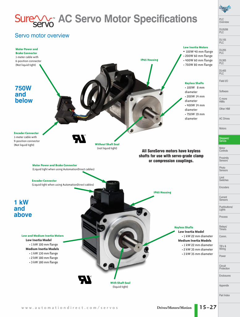
With Shaft Seal(liquid tight)
IP65 Housing
IP65 Housing
Low and Medium Inertia Motors
Low Inertia Model• 1 kW 100 mm flange
Medium Inertia Models• 1 kW 130 mm flange• 2 kW 180 mm flange• 3 kW 180 mm flange
Low Inertia Motors
• 100W 40 mm flange• 200W 60 mm flange• 400W 60 mm flange• 750W 80 mm flange
Keyless Shafts
Low Inertia Model• 1 kW 22 mm diameter
Medium Inertia Models• 1 kW 22 mm diameter• 2 kW 35 mm diameter• 3 kW 35 mm diameter
Keyless Shafts
• 100W 8 mmdiameter• 200W 14 mmdiameter• 400W 14 mmdiameter• 750W 19 mmdiameter
Motor Power and Brake Connector(Liquid tight when using AutomationDirect cables)
Without Shaft Seal(not liquid tight)
Encoder Connector(Liquid tight when using AutomationDirect cables)
Encoder Connector1-meter cable with9-position connector(Not liquid tight)
Motor Power and Brake Connector1-meter cable with6-position connector(Not liquid tight)
All SureServo motors have keylessshafts for use with servo-grade clamp
or compression couplings.
Servo motor overview
750Wandbelow
1 kWandabove
w w w . a u t o m a t i o n d i r e c t . c o m / s e r v o s 15–27Drives/Motors/Motion
PLC Overview
DL05/06 PLC
DL105 PLC
DL205 PLC
DL305 PLC
DL405 PLC
Field I/O
Software
C-more HMIs
Other HMI
AC Drives
Motors
Steppers/Servos
Motor Controls
ProximitySensors
Photo Sensors
Limit Switches
Encoders
CurrentSensors
Pushbuttons/Lights
Process
Relays/Timers
Comm.
TB’s & Wiring
Power
CircuitProtection
Enclosures
Appendix
Part Index
2007_tsureservo_unpriced:2007_tsureservo_priced.qxd 9/10/2007 4:24 PM Page 15–27
1 - 8 0 0 - 6 3 3 - 0 4 0 515–28 Drives/Motors/Motion
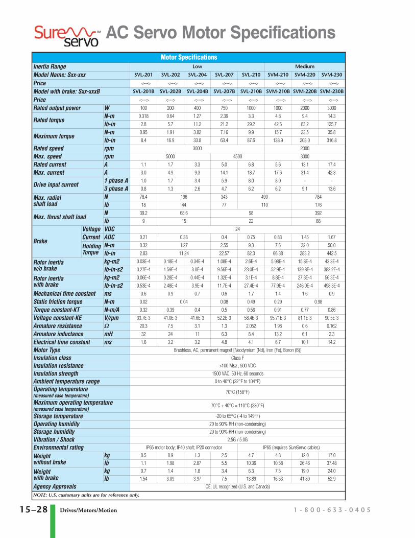
AC Servo Motor SpecificationsMotor Specifications
Inertia Range Low Medium
Model Name: Sxx-xxx SVL-201 SVL-202 SVL-204 SVL-207 SVL-210 SVM-210 SVM-220 SVM-230
Price <---> <---> <---> <---> <---> <---> <---> <--->
Model with brake: Sxx-xxxB SVL-201B SVL-202B SVL-204B SVL-207B SVL-210B SVM-210B SVM-220B SVM-230B
Price <---> <---> <---> <---> <---> <---> <---> <--->
Rated output power W 100 200 400 750 1000 1000 2000 3000
Rated torqueN-m 0.318 0.64 1.27 2.39 3.3 4.8 9.4 14.3
lb-in 2.8 5.7 11.2 21.2 29.2 42.5 83.2 125.7
Maximum torqueN-m 0.95 1.91 3.82 7.16 9.9 15.7 23.5 35.8
lb-in 8.4 16.9 33.8 63.4 87.6 138.9 208.0 316.8
Rated speed rpm 3000 2000
Max. speed rpm 5000 4500 3000
Rated current A 1.1 1.7 3.3 5.0 6.8 5.6 13.1 17.4
Max. current A 3.0 4.9 9.3 14.1 18.7 17.6 31.4 42.3
Drive input current1 phase A 1.0 1.7 3.4 5.9 8.0 8.0 - -
3 phase A 0.8 1.3 2.6 4.7 6.2 6.2 9.1 13.6
Max. radialshaft load
N 78.4 196 343 490 784
lb 18 44 77 110 176
Max. thrust shaft loadN 39.2 68.6 98 392
lb 9 15 22 88
Brake
Voltage VDC 24
Current ADC 0.21 0.38 0.4 0.75 0.83 1.45 1.67
HoldingTorque
N-m 0.32 1.27 2.55 9.3 7.5 32.0 50.0
lb-in 2.83 11.24 22.57 82.3 66.38 283.2 442.5
Rotor inertiaw/o brake
kg-m2 0.03E-4 0.18E-4 0.34E-4 1.08E-4 2.6E-4 5.98E-4 15.8E-4 43.3E-4
lb-in-s2 0.27E-4 1.59E-4 3.0E-4 9.56E-4 23.0E-4 52.9E-4 139.8E-4 383.2E-4
Rotor inertiawith brake
kg-m2 0.06E-4 0.28E-4 0.44E-4 1.32E-4 3.1E-4 8.8E-4 27.8E-4 56.3E-4
lb-in-s2 0.53E-4 2.48E-4 3.9E-4 11.7E-4 27.4E-4 77.9E-4 246.0E-4 498.3E-4
Mechanical time constant ms 0.6 0.9 0.7 0.6 1.7 1.4 1.6 0.9
Static friction torque N-m 0.02 0.04 0.08 0.49 0.29 0.98
Torque constant-KT N-m/A 0.32 0.39 0.4 0.5 0.56 0.91 0.77 0.86
Voltage constant-KE V/rpm 33.7E-3 41.0E-3 41.6E-3 52.2E-3 58.4E-3 95.71E-3 81.1E-3 90.5E-3
Armature resistance Ω 20.3 7.5 3.1 1.3 2.052 1.98 0.6 0.162
Armature inductance mH 32 24 11 6.3 8.4 13.2 6.1 2.3
Electrical time constant ms 1.6 3.2 3.2 4.8 4.1 6.7 10.1 14.2
Motor Type Brushless, AC, permanent magnet [Neodymium (Nd), Iron (Fe), Boron (B)]
Insulation class Class F
Insulation resistance >100 MΩ , 500 VDC
Insulation strength 1500 VAC, 50 Hz, 60 seconds
Ambient temperature range 0 to 40°C (32°F to 104°F)
Operating temperature (measured case temperature)
70°C (158°F)
Maximum operating temperature(measured case temperature)
70°C + 40°C = 110°C (230°F)
Storage temperature -20 to 65°C (-4 to 149°F)
Operating humidity 20 to 90% RH (non-condensing)
Storage humidity 20 to 90% RH (non-condensing)
Vibration / Shock 2.5G / 5.0G
Environmental rating IP65 motor body; IP40 shaft; IP20 connector IP65 (requires SureServo cables)
Weightwithout brake
kg 0.5 0.9 1.3 2.5 4.7 4.8 12.0 17.0
lb 1.1 1.98 2.87 5.5 10.36 10.58 26.46 37.48
Weightwith brake
kg 0.7 1.4 1.8 3.4 6.3 7.5 19.0 24.0
lb 1.54 3.09 3.97 7.5 13.89 16.53 41.89 52.9
Agency Approvals CE; UL recognized (U.S. and Canada)
NOTE: U.S. customary units are for reference only.
230 VACSingle-phase
or Three-phase50/60 Hz
SIGN/SIGNPULSE/PULSET-REFGND
373641431813, 44
RST
L2L1
547910214,1 613,1 5
PDCUVW
(FG)
A/AB
/BZ
/Z+5VGND
CN2
MCCB
±10V
SVC-Exx-xxxEncoderCable Set
MCServo Drive
PulseGenerator
ServoMotor
Encoder
VDDCOM +COM -DI 1DI 2DI 3DI 4DI 5DI 6DI 7DI 8
1711
91034833323130
45,47,4 9
DO 1 +DO 1 -DO 2 +DO 2 -DO 3 +DO 3 -DO 4 +DO 4 -DO 5 +DO 5 -
7654321262827
CN1
CN1
Com.Trig. (Pr mode)/Clear Com. (Pt mode)
Alarm ResetReverse Inhibit OvertravelForward Inhibit Overtravel
Fault Stop
1612,13,1915
MON 1GNDMON 2
212225235024
OA/OAOB/OBOZ/OZ
SG
CN1
CN1
A phase pulse
B phase pulse
Z phase pulse
654321
RS422 TXD-RS422 TXD+RS422 RXD- & RS232 RXRS422 RXD+RS232 TXGND
CN3
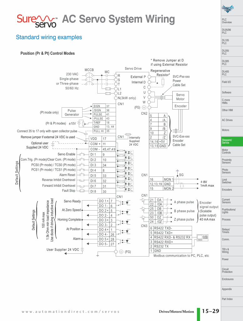
Position (Pr & Pt) Control Modes
(Pt mode only)
(Pr & Pt modes)
PCS0 (Pr mode) / TCS0 (Pt mode)PCS1 (Pr mode) / TCS1 (Pt mode)
Encodersignal output(Scalablepulse output)
SVC-Pxx-xxxPowerCable Set
Servo Ready
At Zero Speed
Homing Complete
Alarm
Servo Enable
(FG)
InternallySupplied24 VDC
Remove jumper if external 24 VDC is usedOptional user
Supplied 24 VDC
User Supplier 24 VDC
Defa
ult S
ettin
gs
ExternalInternal
+_ 8V1mA max
40 mA max
PULL HI 35Connect 35 to 17 only with open collector pulse
At Position100 m
A ma
x1.5
k Ohm
min
load i
mped
ance
Use d
iode i
f driv
ing in
ducti
ve lo
ad
CN1
* Remove Jumper at Dif using External Resistor
RegenerativeResistor*
*
N(3kW only)
Defau
lt Sett
ings
Modbus communication to PC, PLC, etc
w w w . a u t o m a t i o n d i r e c t . c o m / s e r v o s 15–29Drives/Motors/Motion
PLC Overview
DL05/06 PLC
DL105 PLC
DL205 PLC
DL305 PLC
DL405 PLC
Field I/O
Software
C-more HMIs
Other HMI
AC Drives
Motors
Steppers/Servos
Motor Controls
ProximitySensors
Photo Sensors
Limit Switches
Encoders
CurrentSensors
Pushbuttons/Lights
Process
Relays/Timers
Comm.
TB’s & Wiring
Power
CircuitProtection
Enclosures
Appendix
Part Index
Standard wiring examples
AC Servo System Wiring
2007_tsureservo_unpriced:2007_tsureservo_priced.qxd 9/10/2007 4:24 PM Page 15–29
1 - 8 0 0 - 6 3 3 - 0 4 0 515–30
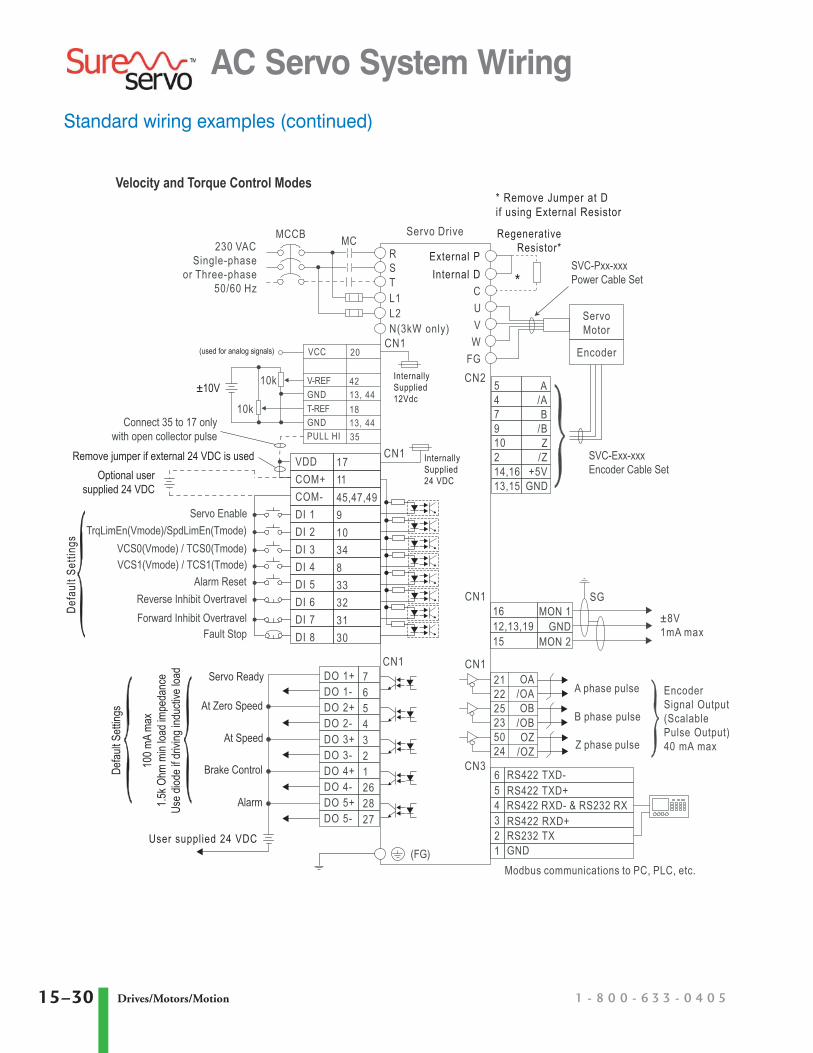
Standard wiring examples (continued)
AC Servo System Wiring
Velocity and Torque Control Modes
RST
L2L1
VDDCOM+COM-DI 1DI 2DI 3DI 4DI 5DI 6DI 7DI 8
1711
91034833323130
45,47,49Servo Enable
TrqLimEn(Vmode)/SpdLimEn(Tmode)VCS0(Vmode) / TCS0(Tmode)VCS1(Vmode) / TCS1(Tmode)
Alarm ResetReverse Inhibit OvertravelForward Inhibit Overtravel
Fault Stop
DO 1+DO 1-DO 2+DO 2-DO 3+DO 3-DO 4+DO 4-DO 5+DO 5-
7654321262827
CN1
CN1
Servo Drive
VCC 20
547910214,1613,15
CUVW
FG
A/AB
/BZ
/Z+5V
GND
CN2
1612,13,1915
MON 1GND
MON 2
SGCN1
212225235024
OA/OAOB
/OBOZ
/OZCN3
CN1
A phase pulse
B phase pulse
Z phase pulse
EncoderSignal Output(ScalablePulse Output)40 mA max
SVC-Exx-xxxEncoder Cable Set
ServoMotor
Encoder
SVC-Pxx-xxxPower Cable Set
External PInternal D
* Remove Jumper at Dif using External Resistor
Remove jumper if external 24 VDC is usedOptional user
supplied 24 VDC
PULL HI 35Connect 35 to 17 only
with open collector pulse
V-REFGND
4213, 44
T-REFGND
1813, 44
10k
10k
Servo Ready
At Zero Speed
At Speed
Alarm
User supplied 24 VDC
Brake Control100 m
A ma
x1.5
k Ohm
min
load i
mped
ance
Use d
iode i
f driv
ing in
ducti
ve lo
ad
±10V
±8V1mA max
Defa
ult S
ettin
gs
(used for analog signals)
(FG)
CN1
InternallySupplied24 VDC
654321
RS422 TXD-RS422 TXD+RS422 RXD- & RS232 RXRS422 RXD+RS232 TXGND
RegenerativeResistor*
*
InternallySupplied12Vdc
230 VACSingle-phase
or Three-phase50/60 Hz
N(3kW only)
Defau
lt Sett
ings
Modbus communications to PC, PLC, etc.
MCCB MC
Drives/Motors/Motion
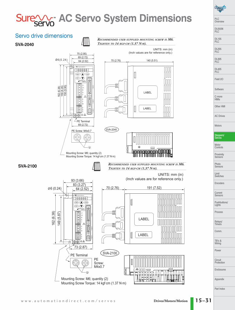
Servo drive dimensionsSVA-2040
SVA-2100
AC Servo System Dimensions
PE Screw: M4x0.7 SVA-2040
Mounting Screw: M6; quantity (2)Mounting Screw Torque: 14 kgf·cm (1.37 N·m)
70 (2.76) 140 (5.51)
LABEL
LABEL
75 (2.95)69 (2.72)64 (2.52)
162
(6.3
8)15
9 (6
.26)
150
(5.9
0)
Ø 6 ( 0 . 2 4 )
L1
L2
R
S
T
U
V
W
PDC
CN1
CN2
CN3
PE Terminal69 (2.72)
Sureservo
MODE ENTER
NEXT
AUTOMATIONDIRECT
UNITS: mm (in)(Inch values are for reference only.)
PEScrew:M4x0.7
SVA-2100PE Terminal
70 (2.76) 191 (7.52)
LABEL
LABEL
93 (3.66)83 (3.27)
64 (2.52)
162
(6.3
8)14
9 (5
.87)
Ø6 (0.24)
L1
L2
R
S
T
U
V
W
PDC
CN1
CN2
CN3
73 (2.87)
MODE ENTER
NEXT
AUTOMATIONDIRECT
Sureservo
UNITS: mm (in)(Inch values are for reference only.)
Mounting Screw: M6; quantity (2)Mounting Screw Torque: 14 kgf·cm (1.37 N·m)
RECOMMENDED USER SUPPLIED MOUNTING SCREW IS M6.TIGHTEN TO 14 KGF·CM (1.37 N·M).
RECOMMENDED USER SUPPLIED MOUNTING SCREW IS M6.TIGHTEN TO 14 KGF·CM (1.37 N·M).
w w w . a u t o m a t i o n d i r e c t . c o m / s e r v o s 15–31Drives/Motors/Motion
PLC Overview
DL05/06 PLC
DL105 PLC
DL205 PLC
DL305 PLC
DL405 PLC
Field I/O
Software
C-more HMIs
Other HMI
AC Drives
Motors
Steppers/Servos
Motor Controls
ProximitySensors
Photo Sensors
Limit Switches
Encoders
CurrentSensors
Pushbuttons/Lights
Process
Relays/Timers
Comm.
TB’s & Wiring
Power
CircuitProtection
Enclosures
Appendix
Part Index
2007_tsureservo_unpriced:2007_tsureservo_priced.qxd 9/10/2007 4:24 PM Page 15–31
1 - 8 0 0 - 6 3 3 - 0 4 0 515–32 Drives/Motors/Motion
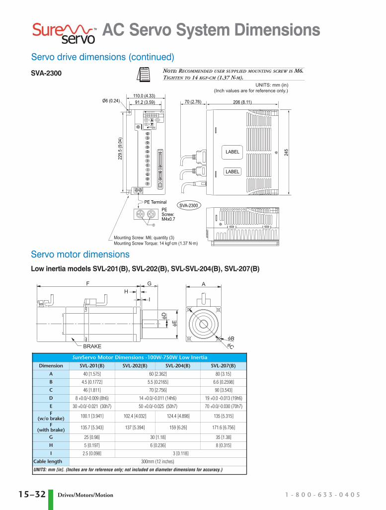
SVA-2300
Servo drive dimensions (continued)
Servo motor dimensionsLow inertia models SVL-201(B), SVL-202(B), SVL-SVL-204(B), SVL-207(B)
AC Servo System Dimensions
PEScrew:M4x0.7
SVA-2300PE Terminal
70 (2.76) 206 (8.11)
LABEL
LABEL
245
110.0 (4.33)91.2 (3.59)
229.
5 (9
.04)
MODE ENTER
NEXT
AUTOMATIONDIRECT
Sureservo
O6 (0.24)
UNITS: mm (in)(Inch values are for reference only.)
Mounting Screw: M6; quantity (3)Mounting Screw Torque: 14 kgf·cm (1.37 N·m)
BRAKE
FH
G
I
φD
φE
φBφC
A
SureServo Motor Dimensions -100W-750W Low Inertia
Dimension SVL-201(B) SVL-202(B) SVL-204(B) SVL-207(B)
A 40 [1.575] 60 [2.362] 80 [3.15]
B 4.5 [0.1772] 5.5 [0.2165] 6.6 [0.2598]
C 46 [1.811] 70 [2.756] 90 [3.543]
D 8 +0.0/-0.009 (8h6) 14 +0.0/-0.011 (14h6) 19 +0.0 -0.013 (19h6)
E 30 +0.0/-0.021 (30h7) 50 +0.0/-0.025 (50h7) 70 +0.0/-0.030 (70h7)F
(w/o brake) 100.1 [3.941] 102.4 [4.032] 124.4 [4.898] 135 [5.315]
F(with brake) 135.7 [5.343] 137 [5.394] 159 [6.26] 171.6 [6.756]
G 25 [0.98] 30 [1.18] 35 [1.38]
H 5 [0.197] 6 [0.236] 8 [0.315]
I 2.5 [0.098] 3 [0.118]
Cable length 300mm (12 inches)
UNITS: mm [in]. (Inches are for reference only; not included on diameter dimensions for accuracy.)
NOTE: RECOMMENDED USER SUPPLIED MOUNTING SCREW IS M6.TIGHTEN TO 14 KGF·CM (1.37 N·M).
2007_tsureservo_unpriced:2007_tsureservo_priced.qxd 9/10/2007 4:24 PM Page 15–32

w w w . a u t o m a t i o n d i r e c t . c o m / s e r v o s 15–33Drives/Motors/Motion
PLC Overview
DL05/06 PLC
DL105 PLC
DL205 PLC
DL305 PLC
DL405 PLC
Field I/O
Software
C-more HMIs
Other HMI
AC Drives
Motors
Steppers/Servos
Motor Controls
ProximitySensors
Photo Sensors
Limit Switches
Encoders
CurrentSensors
Pushbuttons/Lights
Process
Relays/Timers
Comm.
TB’s & Wiring
Power
CircuitProtection
Enclosures
Appendix
Part Index
Servo motor dimensions (continued)Low inertia models SVL-210(B)
Medium inertia models SVM-210(B), SVM-220(B), SVM-230(B)
AC Servo System Dimensions
BRAKE
F
H
G
I
φD φE
φBφC
A SureServo Motor Dimensions -1000W Low Inertia
Dimension SVL-210(B)
A 100 [3.937]B 9 [0.3543]C 115 +0.2/-0.2 [4.258]D 22 +0.0/-0.013 (22h6) E 95 +0.0/-0.035 (95h7) F
(w/o brake) 158 [6.22]
F(with brake) 190 [7.48]
G 45 [1.77]H 17 [0.669]I 7 [0.28]
UNITS: mm [in] (Inches are for reference only; not included ondiameter dimensions for accuracy.)
SureServo Motor Dimensions -1000W-3000W Medium Inertia
Dimension SVM-210(B) SVM-220(B) SVM-230(B)
A 130 [5.118] 180 [7.087]B 9 [0.3543] 13.5 [0.5315]C 145 +0.2/-0.2 [5.709] 200 +0.2/-0.2 [7.874]D 22 +0.0/-0.013 (22h6) 35 +0.0/-0.016 (35h6) E 110 +0.0/-0.035 (110h7) 114.3 +0/-0.035 (114.3h7)F
(w/o brake) 143 [5.63] 164 [6.457] 212 [8.35]
F(with brake) 181 [7.126] 213 [8.386] 258 [10.16]
G 55 [2.17] 75 [2.95]H 15 [0.591] 20 [0.787]I 4 [0.157]
UNITS: mm [in] (Inches are for reference only; not included on diameter dimensions for accuracy.)
F
H
G
I
φD φE
φC
A
φB
2007_tsureservo_unpriced:2007_tsureservo_priced.qxd 9/10/2007 4:24 PM Page 15–33
1 - 8 0 0 - 6 3 3 - 0 4 0 515–34 Drives/Motors/Motion
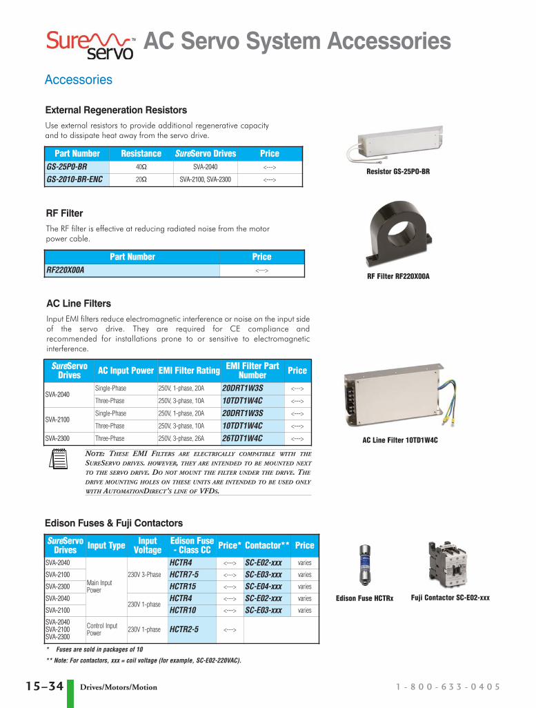
Accessories
AC Servo System Accessories
SureServoDrives Input Type Input
VoltageEdison Fuse- Class CC Price* Contactor** Price
SVA-2040
Main InputPower
230V 3-Phase
HCTR4 <---> SC-E02-xxx varies
SVA-2100 HCTR7-5 <---> SC-E03-xxx varies
SVA-2300 HCTR15 <---> SC-E04-xxx varies
SVA-2040230V 1-phase
HCTR4 <---> SC-E02-xxx varies
SVA-2100 HCTR10 <---> SC-E03-xxx varies
SVA-2040SVA-2100SVA-2300
Control InputPower 230V 1-phase HCTR2-5 <--->
SureServoDrives AC Input Power EMI Filter Rating EMI Filter Part
Number Price
SVA-2040Single-Phase 250V, 1-phase, 20A 20DRT1W3S <--->
Three-Phase 250V, 3-phase, 10A 10TDT1W4C <--->
SVA-2100Single-Phase 250V, 1-phase, 20A 20DRT1W3S <--->
Three-Phase 250V, 3-phase, 10A 10TDT1W4C <--->
SVA-2300 Three-Phase 250V, 3-phase, 26A 26TDT1W4C <--->
Part Number PriceRF220X00A <--->
Fuji Contactor SC-E02-xxxEdison Fuse HCTRx
RF Filter RF220X00A
RF FilterThe RF filter is effective at reducing radiated noise from the motorpower cable.
Edison Fuses & Fuji Contactors
AC Line FiltersInput EMI filters reduce electromagnetic interference or noise on the input sideof the servo drive. They are required for CE compliance andrecommended for installations prone to or sensitive to electromagneticinterference.
Resistor GS-25PO-BR
* Fuses are sold in packages of 10
** Note: For contactors, xxx = coil voltage (for example, SC-E02-220VAC).
AC Line Filter 10TD1W4C
Part Number Resistance SureServo Drives PriceGS-25P0-BR 40Ω SVA-2040 <--->
GS-2010-BR-ENC 20Ω SVA-2100, SVA-2300 <--->
NOTE: THESE EMI FILTERS ARE ELECTRICALLY COMPATIBLE WITH THE
SURESERVO DRIVES. HOWEVER, THEY ARE INTENDED TO BE MOUNTED NEXT
TO THE SERVO DRIVE. DO NOT MOUNT THE FILTER UNDER THE DRIVE. THE
DRIVE MOUNTING HOLES ON THESE UNITS ARE INTENDED TO BE USED ONLY
WITH AUTOMATIONDIRECT’S LINE OF VFDS.
External Regeneration ResistorsUse external resistors to provide additional regenerative capacityand to dissipate heat away from the servo drive.
2007_tsureservo_unpriced:2007_tsureservo_priced.qxd 9/10/2007 4:25 PM Page 15–34


![SERVO-DRIVE - [Blum Connect]connect.blum.com/files/brochure/BRO014_SERVODRIVEforTBX_ZZ1.pdf · 4 5 Create more freedom of motion with SERVO-DRIVE SERVO-DRIVE at a glance SERVO-DRIVE](https://img.pdfslide.us/doc/110x75/5b705e257f8b9abb7c8dc582/servo-drive-blum-connect-4-5-create-more-freedom-of-motion-with-servo-drive.jpg)