Embed Size (px)
Citation preview
AUTOMATIC PARKING OF SELF-DRIVING CAR BASED ON LIDAR
Bijun Lee a, Yang Weia, I. Yuan Guo a
a State Key Laboratory of Information Engineering in Surveying, Mapping and Remote Sensing, Wuhan University, China -
(Lee, guoyuan, yangwei)@whu.edu.cn
Commission VI, WG VI/4
KEY WORDS: Automatic driving, Parallel driving, Perpendicular driving, Path planning, Fuzzy logic controller
ABSTRACT:
To overcome the deficiency of ultrasonic sensor and camera, this paper proposed a method of autonomous parking based on the self-
driving car, using HDL-32E LiDAR. First the 3-D point cloud data was preprocessed. Then we calculated the minimum size of parking
space according to the dynamic theories of vehicle. Second the rapidly-exploring random tree algorithm (RRT) algorithm was improved
in two aspects based on the moving characteristic of autonomous car. And we calculated the parking path on the basis of the vehicle’s
dynamics and collision constraints. Besides, we used the fuzzy logic controller to control the brake and accelerator in order to realize
the stably of speed. At last the experiments were conducted in an autonomous car, and the results show that the proposed automatic
parking system is feasible and effective.
1. INTRODUCTION
Autonomous vehicle is a hot research area now. And automatic
parking as an important part of autonomous vehicle have been
concerned by more and more researchers. Besides, as the number
of car increases, parking has becoming an increasingly difficult
matter. In this case, automatic parking is an indispensable part in
our life.
The automatic parking system consists of target position
designation, path planning and parking guidance (Wang, Song et
al. 2014). The scanning laser radar (Jung, Cho et al. 2008),
ultrasonic sensor, (Park, Kim et al. 2008) and binocular
(Kaempchen, Franke et al. 2002) are used to gather exteroceptive
information and identify the parking spot. However the ultrasonic
sensor can’t adapt to the situation that the both sides of parking
place is empty and there are lots of blind spots when using camera.
In order to improve the efficiency of automatic parking, we chose
the HDL-32 LiDAR to detect parking spot.
About the path planning and control, there are mainly about two
categories(Marouf, Pollard et al. 2014). One is based on the fuzzy
logic to transfer human driver’s parking skill to automatic
parking controller(Laugier and Paromtchik 1996). Yanan Zhao
designed novel fuzzy logic controllers using the kinematic model
of a skid steering autonomous ground vehicle((Zhao and Jr 2005).
And Xiyang Yang designed a fuzzy logic control method
combined hierarchical control and variable universe(Yang and
You 2010). However it is difficult to model in this way.
The other one is based on vehicle’s dynamics and constraints to
planning a feasible geometry path in advance, and then the
vehicle is controlled to follow the reference path(Min and Choi
2013). Inoue proposed a path planning method composed of
control laws for the steering angle and the driving velocity (Liu,
Dao et al. 2005). JinZe Song proposed a method to generate
collision-free space based on the differential flat theory and
spline theory (song 2009). This approach requires high control
precision of speed and direction. And it is more appropriate to
apply to autonomous car.
In this paper, we choose the second way. And we proved the RRT
algorithm to plan parking path.
2. PREPROCESSING AND CALCULATING
In order to increase efficiency, the preprocessing and
segmentation of 3-D cloud data is necessary since the large
amount of data. We extracted the available parking space
information by recognizing the geometric feature of stopped car.
2.1 PREPROCESSING OF DATA
In china, traffic keeps on the right of the road. We need to find
the parking spot on the right side of the car. And the obstacle
information on the left side is used to constrain the parking path.
However, the data in the distance will interfere the process of
information extraction and increase the time and calculating cost.
For this reason, we defined the region of interest (ROI). The
distance to the left and right of LiDAR are 8m and 10m and the
distance to the forward and backward of LiDAR are 16m and 8m.
We care about the information of parked cars and the obstacles.
Ground data and the point data of tree are useless for us. The
distance from LiDAR to ground is 2m. And the tree is taller than
LiDAR. So the through filter is used to retain the data -2m<z<0m.
There exist safe distance between parked cars and obstacles.
Based on this feature, the Euclidean cluster is applied to extract
parked cars and obstacles. At last we projected the data to XOY
plane and replaced it by minimum bounding rectangle (MBR).
Figure 1(a) shows the original 3D point cloud. Figure 1(b)
depicts the extracted ROI. The result of Euclidean cluster is
depicted by Figure 1(c). And Figure 1(d) shows the MBR of
parked cars and obstacles.
The distance between MBR compared to the minimum size of
parking spot can determine the area of parking.
The International Archives of the Photogrammetry, Remote Sensing and Spatial Information Sciences, Volume XLII-2/W7, 2017 ISPRS Geospatial Week 2017, 18–22 September 2017, Wuhan, China
This contribution has been peer-reviewed. https://doi.org/10.5194/isprs-archives-XLII-2-W7-241-2017 | © Authors 2017. CC BY 4.0 License.
241
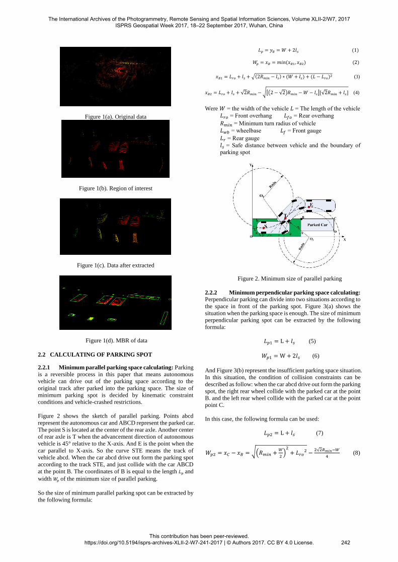
Figure 1(a). Original data
Figure 1(b). Region of interest
Figure 1(c). Data after extracted
Figure 1(d). MBR of data
2.2 CALCULATING OF PARKING SPOT
2.2.1 Minimum parallel parking space calculating: Parking
is a reversible process in this paper that means autonomous
vehicle can drive out of the parking space according to the
original track after parked into the parking space. The size of
minimum parking spot is decided by kinematic constraint
conditions and vehicle-crashed restrictions.
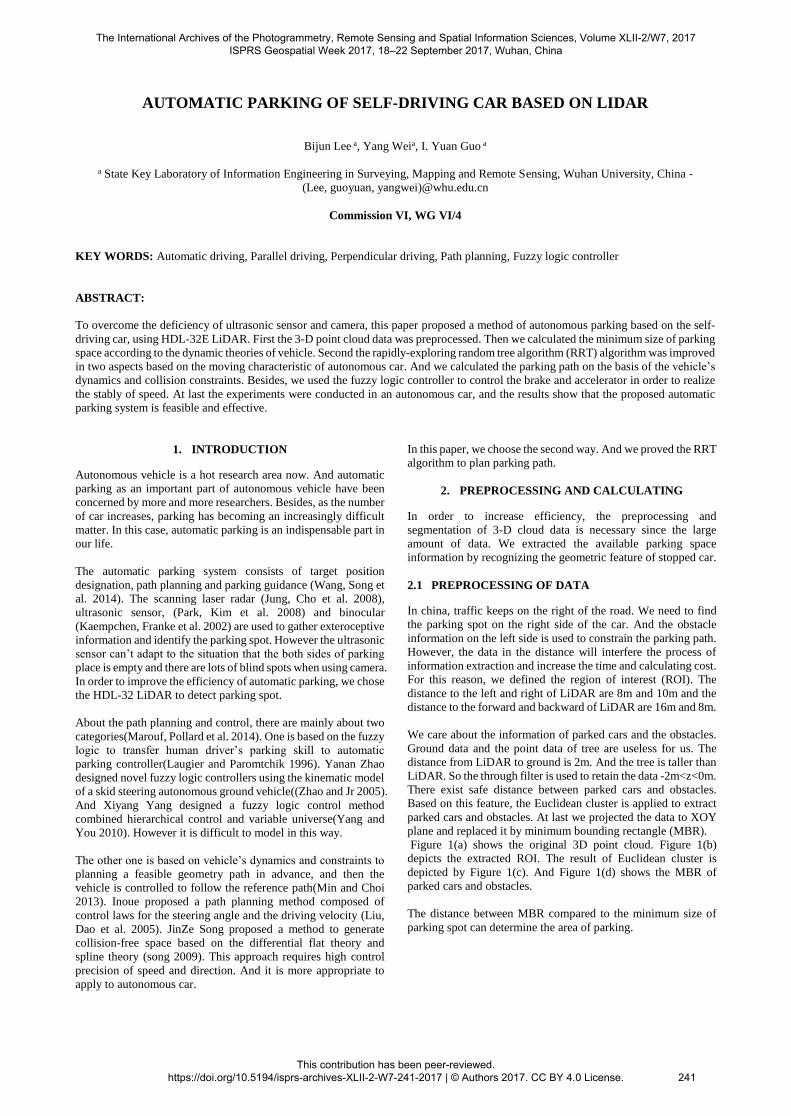
Figure 2 shows the sketch of parallel parking. Points abcd
represent the autonomous car and ABCD represent the parked car.
The point S is located at the center of the rear axle. Another center
of rear axle is T when the advancement direction of autonomous
vehicle is 45° relative to the X-axis. And E is the point when the
car parallel to X-axis. So the curve STE means the track of
vehicle abcd. When the car abcd drive out form the parking spot
according to the track STE, and just collide with the car ABCD
at the point B. The coordinates of B is equal to the length 𝐿𝑝 and
width 𝑊𝑝 of the minimum size of parallel parking.
So the size of minimum parallel parking spot can be extracted by
the following formula:
𝐿𝑝 = 𝑦𝐵 = 𝑊 + 2𝑙𝑠 (1)
𝑊𝑝 = 𝑥𝐵 = 𝑚𝑖𝑛(𝑥𝐵1, 𝑥𝐵2) (2)
𝑥𝐵1 = 𝐿𝑟𝑜 + 𝑙𝑠 +√(2𝑅𝑚𝑖𝑛 − 𝑙𝑠) ∗ (𝑊 + 𝑙𝑠) + (𝐿 − 𝐿𝑟𝑜)2 (3)
𝑥𝐵2 = 𝐿𝑟𝑜 + 𝑙𝑠 + √2𝑅𝑚𝑖𝑛 −√[(2 − √2)𝑅𝑚𝑖𝑛 −𝑊 − 𝑙𝑠][√2𝑅𝑚𝑖𝑛 + 𝑙𝑠] (4)
Were 𝑊 = the width of the vehicle 𝐿 = The length of the vehicle
𝐿𝑟𝑜 = Front overhang 𝐿𝑓𝑜 = Rear overhang
𝑅𝑚𝑖𝑛 = Minimum turn radius of vehicle
𝐿𝑤𝑏 = wheelbase 𝐿𝑓 = Front gauge
𝐿𝑟 = Rear gauge
𝑙𝑠 = Safe distance between vehicle and the boundary of
parking spot
Figure 2. Minimum size of parallel parking
2.2.2 Minimum perpendicular parking space calculating: Perpendicular parking can divide into two situations according to
the space in front of the parking spot. Figure 3(a) shows the
situation when the parking space is enough. The size of minimum
perpendicular parking spot can be extracted by the following
formula:
𝐿𝑝1 = L + 𝑙𝑠 (5)
𝑊𝑝1 = W+ 2𝑙𝑠 (6)
And Figure 3(b) represent the insufficient parking space situation.
In this situation, the condition of collision constraints can be
described as follow: when the car abcd drive out form the parking
spot, the right rear wheel collide with the parked car at the point
B. and the left rear wheel collide with the parked car at the point
point C.
In this case, the following formula can be used:
𝐿𝑝2 = L + 𝑙𝑠 (7)
𝑊𝑝2 = 𝑥𝐶 − 𝑥𝐵 = √(𝑅𝑚𝑖𝑛 +𝑊
2)2+ 𝐿𝑟𝑜
2 −2√2𝑅𝑚𝑖𝑛−𝑊
4 (8)
The International Archives of the Photogrammetry, Remote Sensing and Spatial Information Sciences, Volume XLII-2/W7, 2017 ISPRS Geospatial Week 2017, 18–22 September 2017, Wuhan, China
This contribution has been peer-reviewed. https://doi.org/10.5194/isprs-archives-XLII-2-W7-241-2017 | © Authors 2017. CC BY 4.0 License.
242
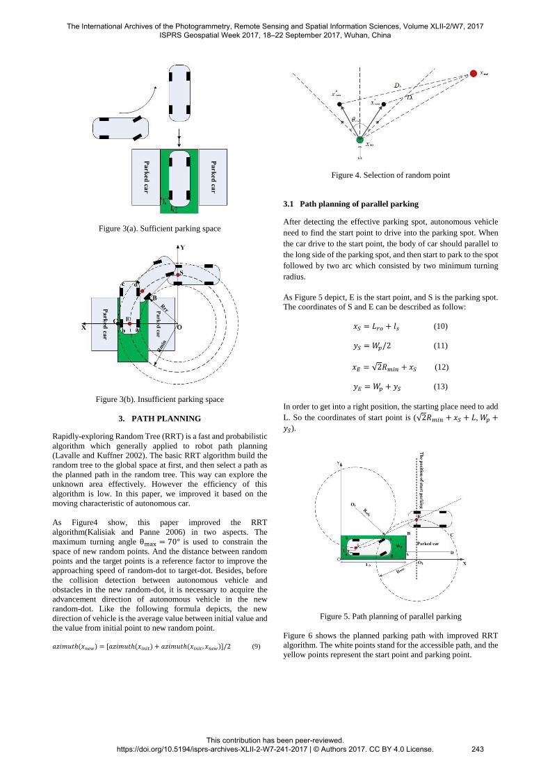
Figure 3(a). Sufficient parking space
Figure 3(b). Insufficient parking space
3. PATH PLANNING
Rapidly-exploring Random Tree (RRT) is a fast and probabilistic
algorithm which generally applied to robot path planning
(Lavalle and Kuffner 2002). The basic RRT algorithm build the
random tree to the global space at first, and then select a path as
the planned path in the random tree. This way can explore the
unknown area effectively. However the efficiency of this
algorithm is low. In this paper, we improved it based on the
moving characteristic of autonomous car.
As Figure4 show, this paper improved the RRT
algorithm(Kalisiak and Panne 2006) in two aspects. The
maximum turning angle θmax = 70° is used to constrain the
space of new random points. And the distance between random
points and the target points is a reference factor to improve the
approaching speed of random-dot to target-dot. Besides, before
the collision detection between autonomous vehicle and
obstacles in the new random-dot, it is necessary to acquire the
advancement direction of autonomous vehicle in the new
random-dot. Like the following formula depicts, the new
direction of vehicle is the average value between initial value and
the value from initial point to new random point.
𝑎𝑧𝑖𝑚𝑢𝑡ℎ(𝑥𝑛𝑒𝑤) = [𝑎𝑧𝑖𝑚𝑢𝑡ℎ(𝑥𝑖𝑛𝑖𝑡) + 𝑎𝑧𝑖𝑚𝑢𝑡ℎ(𝑥𝑖𝑛𝑖𝑡, 𝑥𝑛𝑒𝑤)]/2 (9)
Figure 4. Selection of random point
3.1 Path planning of parallel parking
After detecting the effective parking spot, autonomous vehicle
need to find the start point to drive into the parking spot. When
the car drive to the start point, the body of car should parallel to
the long side of the parking spot, and then start to park to the spot
followed by two arc which consisted by two minimum turning
radius.
As Figure 5 depict, E is the start point, and S is the parking spot.
The coordinates of S and E can be described as follow:
𝑥𝑆 = 𝐿𝑟𝑜 + 𝑙𝑠 (10)
𝑦𝑆 = 𝑊𝑝/2 (11)
𝑥𝐸 = √2𝑅𝑚𝑖𝑛 + 𝑥𝑆 (12)
𝑦𝐸 = 𝑊𝑝 + 𝑦𝑆 (13)
In order to get into a right position, the starting place need to add
L. So the coordinates of start point is (√2𝑅𝑚𝑖𝑛 + 𝑥𝑆 + 𝐿,𝑊𝑝 +
𝑦𝑆).
Figure 5. Path planning of parallel parking
Figure 6 shows the planned parking path with improved RRT
algorithm. The white points stand for the accessible path, and the
yellow points represent the start point and parking point.
The International Archives of the Photogrammetry, Remote Sensing and Spatial Information Sciences, Volume XLII-2/W7, 2017 ISPRS Geospatial Week 2017, 18–22 September 2017, Wuhan, China
This contribution has been peer-reviewed. https://doi.org/10.5194/isprs-archives-XLII-2-W7-241-2017 | © Authors 2017. CC BY 4.0 License.
243
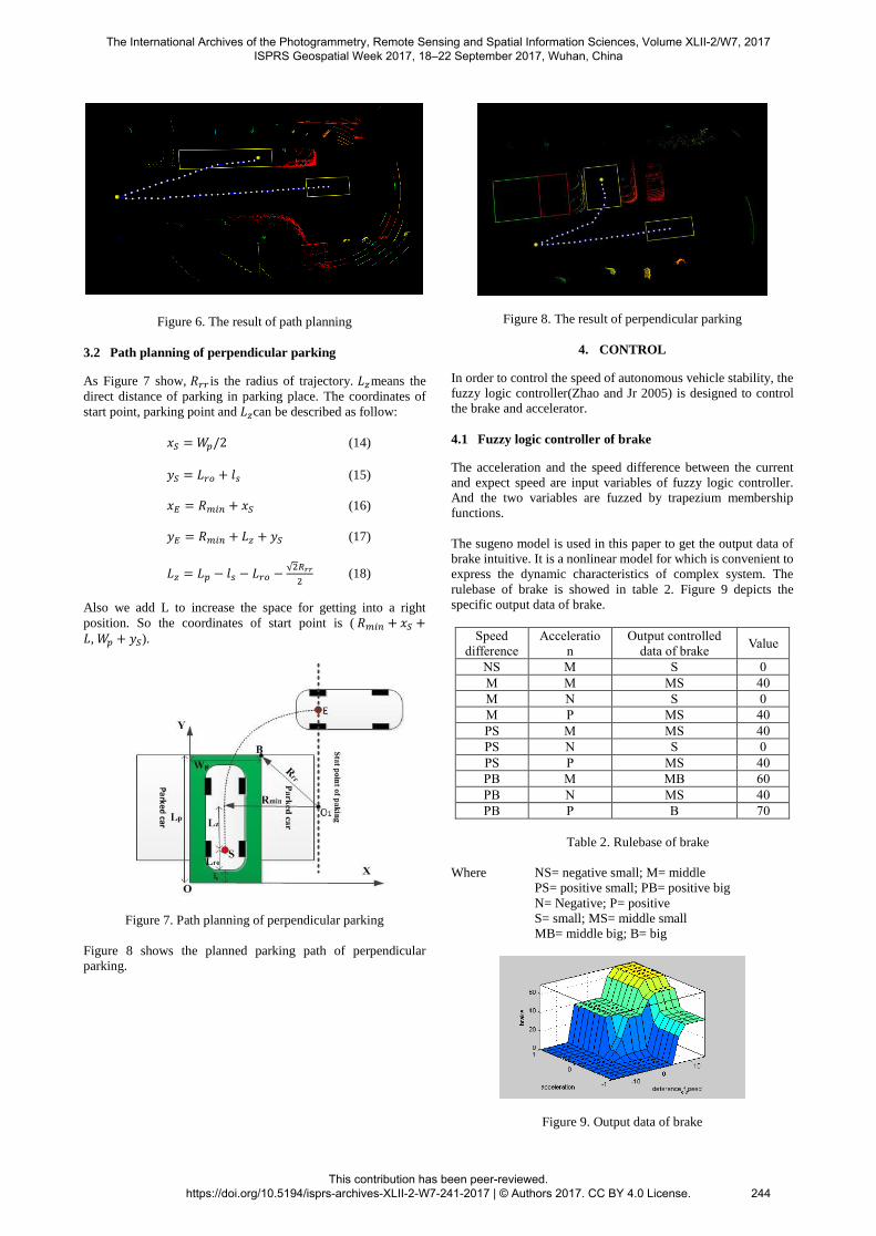
Figure 6. The result of path planning
3.2 Path planning of perpendicular parking
As Figure 7 show, 𝑅𝑟𝑟 is the radius of trajectory. 𝐿𝑧means the
direct distance of parking in parking place. The coordinates of
start point, parking point and 𝐿𝑧can be described as follow:
𝑥𝑆 = 𝑊𝑝/2 (14)
𝑦𝑆 = 𝐿𝑟𝑜 + 𝑙𝑠 (15)
𝑥𝐸 = 𝑅𝑚𝑖𝑛 + 𝑥𝑆 (16)
𝑦𝐸 = 𝑅𝑚𝑖𝑛 + 𝐿𝑧 + 𝑦𝑆 (17)
𝐿𝑧 = 𝐿𝑝 − 𝑙𝑠 − 𝐿𝑟𝑜 −√2𝑅𝑟𝑟
2(18)
Also we add L to increase the space for getting into a right
position. So the coordinates of start point is ( 𝑅𝑚𝑖𝑛 + 𝑥𝑆 +𝐿,𝑊𝑝 + 𝑦𝑆).
Figure 7. Path planning of perpendicular parking
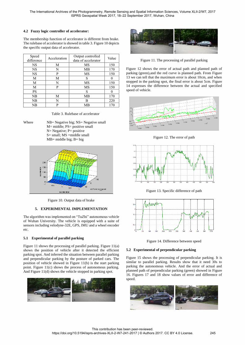
Figure 8 shows the planned parking path of perpendicular
parking.
Figure 8. The result of perpendicular parking
4. CONTROL
In order to control the speed of autonomous vehicle stability, the
fuzzy logic controller(Zhao and Jr 2005) is designed to control
the brake and accelerator.
4.1 Fuzzy logic controller of brake
The acceleration and the speed difference between the current
and expect speed are input variables of fuzzy logic controller.
And the two variables are fuzzed by trapezium membership
functions.
The sugeno model is used in this paper to get the output data of
brake intuitive. It is a nonlinear model for which is convenient to
express the dynamic characteristics of complex system. The
rulebase of brake is showed in table 2. Figure 9 depicts the
specific output data of brake.
Speed
difference
Acceleratio
n
Output controlled
data of brake Value
NS M S 0
M M MS 40
M N S 0
M P MS 40
PS M MS 40
PS N S 0
PS P MS 40
PB M MB 60
PB N MS 40
PB P B 70
Table 2. Rulebase of brake
Where NS= negative small; M= middle
PS= positive small; PB= positive big
N= Negative; P= positive
S= small; MS= middle small
MB= middle big; B= big
Figure 9. Output data of brake
The International Archives of the Photogrammetry, Remote Sensing and Spatial Information Sciences, Volume XLII-2/W7, 2017 ISPRS Geospatial Week 2017, 18–22 September 2017, Wuhan, China
This contribution has been peer-reviewed. https://doi.org/10.5194/isprs-archives-XLII-2-W7-241-2017 | © Authors 2017. CC BY 4.0 License.
244
4.2 Fuzzy logic controller of accelerator:
The membership function of accelerator is different from brake.
The rulebase of accelerator is showed in table 3. Figure 10 depicts
the specific output data of accelerator.
Speed
difference Acceleration
Output controlled
data of accelerator Value
NS M MS 150
NS N MB 170
NS P MS 150
M M S 0
M N MS 150
M P MS 150
PS S 0
NB M MB 170
NB N B 220
NB P MB 170
Table 3. Rulebase of accelerator
Where NB= Negative big; NS= Negative small
M= middle; PS= positive small
N= Negative; P= positive
S= small; MS =middle small
MB= middle big; B= big
Figure 10. Output data of brake
5. EXPERIMENTAL IMPLEMENTATION
The algorithm was implemented on “TuZhi” autonomous vehicle
of Wuhan University. The vehicle is equipped with a suite of
sensors including velodyne-32E, GPS, IMU and a wheel encoder
etc.
5.1 Experimental of parallel parking
Figure 11 shows the processing of parallel parking. Figure 11(a)
shows the position of vehicle after it detected the efficient
parking spot. And inferred the situation between parallel parking
and perpendicular parking by the posture of parked cars. The
position of vehicle showed in Figure 11(b) is the start parking
point. Figure 11(c) shows the process of autonomous parking.
And Figure 11(d) shows the vehicle stopped in parking spot.
Figure 11. The processing of parallel parking
Figure 12 shows the error of actual path and planned path of
parking (green),and the red curve is planned path. From Figure
13 we can tell that the maximum error is about 10cm, and when
stopped in the parking spot, the final error is about 5cm. Figure
14 expresses the difference between the actual and specified
speed of vehicle.
Figure 12. The error of path
Figure 13. Specific difference of path
Figure 14. Difference between speed
5.2 Experimental of perpendicular parking
Figure 15 shows the processing of perpendicular parking. It is
similar to parallel parking. Results show that it need 30s to
parking the autonomous vehicle. And the error of actual and
planned path of perpendicular parking (green) showed in Figure
16. Figures 17 and 18 show values of error and difference of
speed.
The International Archives of the Photogrammetry, Remote Sensing and Spatial Information Sciences, Volume XLII-2/W7, 2017 ISPRS Geospatial Week 2017, 18–22 September 2017, Wuhan, China
This contribution has been peer-reviewed. https://doi.org/10.5194/isprs-archives-XLII-2-W7-241-2017 | © Authors 2017. CC BY 4.0 License.
245
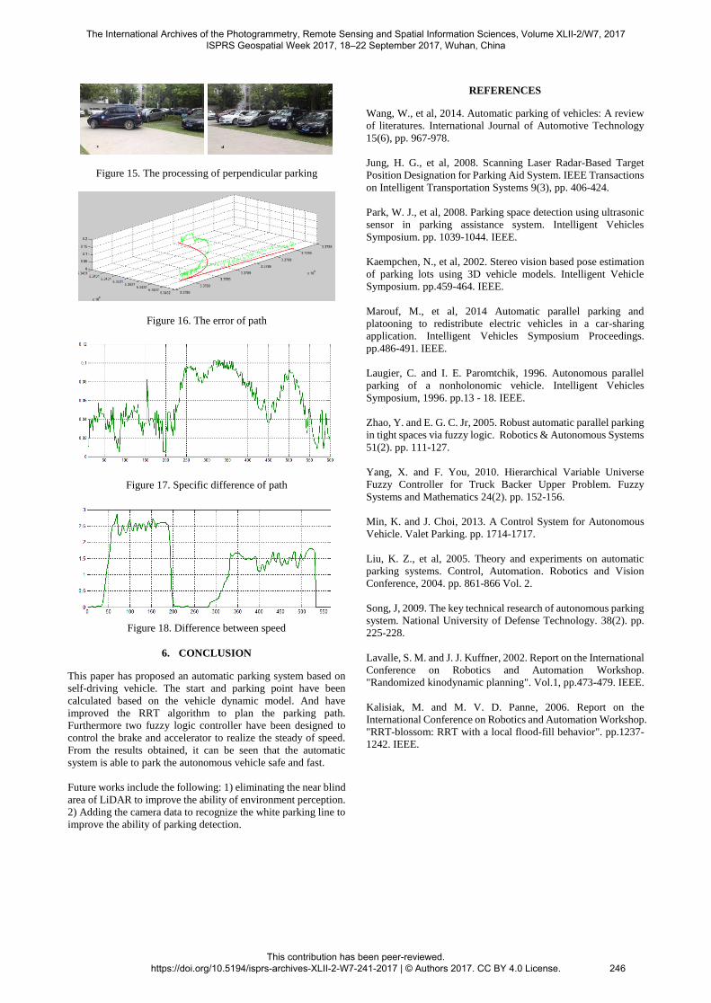
Figure 15. The processing of perpendicular parking
Figure 16. The error of path
Figure 17. Specific difference of path
Figure 18. Difference between speed
6. CONCLUSION
This paper has proposed an automatic parking system based on
self-driving vehicle. The start and parking point have been
calculated based on the vehicle dynamic model. And have
improved the RRT algorithm to plan the parking path.
Furthermore two fuzzy logic controller have been designed to
control the brake and accelerator to realize the steady of speed.
From the results obtained, it can be seen that the automatic
system is able to park the autonomous vehicle safe and fast.
Future works include the following: 1) eliminating the near blind
area of LiDAR to improve the ability of environment perception.
2) Adding the camera data to recognize the white parking line to
improve the ability of parking detection.
REFERENCES
Wang, W., et al, 2014. Automatic parking of vehicles: A review
of literatures. International Journal of Automotive Technology
15(6), pp. 967-978.
Jung, H. G., et al, 2008. Scanning Laser Radar-Based Target
Position Designation for Parking Aid System. IEEE Transactions
on Intelligent Transportation Systems 9(3), pp. 406-424.
Park, W. J., et al, 2008. Parking space detection using ultrasonic
sensor in parking assistance system. Intelligent Vehicles
Symposium. pp. 1039-1044. IEEE.
Kaempchen, N., et al, 2002. Stereo vision based pose estimation
of parking lots using 3D vehicle models. Intelligent Vehicle
Symposium. pp.459-464. IEEE.
Marouf, M., et al, 2014 Automatic parallel parking and
platooning to redistribute electric vehicles in a car-sharing
application. Intelligent Vehicles Symposium Proceedings.
pp.486-491. IEEE.
Laugier, C. and I. E. Paromtchik, 1996. Autonomous parallel
parking of a nonholonomic vehicle. Intelligent Vehicles
Symposium, 1996. pp.13 - 18. IEEE.
Zhao, Y. and E. G. C. Jr, 2005. Robust automatic parallel parking
in tight spaces via fuzzy logic. Robotics & Autonomous Systems
51(2). pp. 111-127.
Yang, X. and F. You, 2010. Hierarchical Variable Universe
Fuzzy Controller for Truck Backer Upper Problem. Fuzzy
Systems and Mathematics 24(2). pp. 152-156.
Min, K. and J. Choi, 2013. A Control System for Autonomous
Vehicle. Valet Parking. pp. 1714-1717.
Liu, K. Z., et al, 2005. Theory and experiments on automatic
parking systems. Control, Automation. Robotics and Vision
Conference, 2004. pp. 861-866 Vol. 2.
Song, J, 2009. The key technical research of autonomous parking
system. National University of Defense Technology. 38(2). pp.
225-228.
Lavalle, S. M. and J. J. Kuffner, 2002. Report on the International
Conference on Robotics and Automation Workshop.
"Randomized kinodynamic planning". Vol.1, pp.473-479. IEEE.
Kalisiak, M. and M. V. D. Panne, 2006. Report on the
International Conference on Robotics and Automation Workshop.
"RRT-blossom: RRT with a local flood-fill behavior". pp.1237-
1242. IEEE.
The International Archives of the Photogrammetry, Remote Sensing and Spatial Information Sciences, Volume XLII-2/W7, 2017 ISPRS Geospatial Week 2017, 18–22 September 2017, Wuhan, China
This contribution has been peer-reviewed. https://doi.org/10.5194/isprs-archives-XLII-2-W7-241-2017 | © Authors 2017. CC BY 4.0 License.
246