Embed Size (px)
Citation preview
Journal of JSAM 70(6): 76~84, 2008Research Paper
Automatic Guidance System in Real-time
Orchard Application (Part1)
-A Novel Research on Coconut Field Application Using Laser Scanner-
Oscar C. BARAWID Jr.*1, Rahman FARROKHI TEIMOURLOU*1,
Noboru NOGUCHI*2, Kazunobu ISHII*2
Abstract
The research objective was to develop an automatic guidance system in a real-time coconut field
application using a laser scanner. Seven methods were used in this research, data and information
gathering, tree row recognition using Hough transform, masking method to get the ROI (region-of-interest), simulated coconut environment, SMA (simple moving average), steering control algorithm,
and experimental test runs. This research dealt with the recognition of tree rows as a straight line,
to be followed by the robot tractor in real-time coconut field straight path navigation.
[Keywords] region-of-interest, laser scanner, Hough transform, SMA (simple moving average), coconut field
Ⅰ Introduction
Presently only a few research institutions are con-
ducting studies on orchard applications using robotics
technology. Barawid et al., (2006) conducted a related
research entitled "Development of an autonomous
navigation system using two-dimensional laser scan-
ner in an orchard application". Rovira-Mas et al., (2005)
also developed a related research entitled "The Hough
transform based vision algorithm for crop row detec-
tion method for tractor automated guidance". Kise et
al., (2005) developed a similar research for crop row
detection using stereovision based agricultural ma-
chinery entitled "A stereovision based crop row detec-
tion method for tractor automated guidance". All of
these researches focused solely on general orchard
application and row crop detection.
This paper aims to describe the automatic guidance
system in a coconut field. The coconut industry is one
of the top five net foreign exchange earners with an
income of US$ 760M per annum in the Philippines. 3.5
million farmers are directly engaged in coconut culti-
vation. Developing an autonomous navigation system
in a coconut field will help the farmers in the Philip-
pines to collect the harvested fruits, to save time and
effort in harvesting coconuts, to perform an autono-
mous weeding, and to make coconut farming to be
highly-industrialized. These are the reasons why the
coconut orchard was chosen as the subject of study.
The coconut is a member of the palm family. It
grows to 30m tall, with pinnate leaves 4-6m long.
The trees flourish in tropical climates as in the Philip-
pines. One can see these trees lining the vast shore-
lines. The large bulk of the trees however are con-
tained in plantations owned by private individuals.
Continuous cultivation is due to marketing desirabili-
ty of the tree. The coconut has long been called the"tree of life" by the Filipinos due to its
abundant uses.
Water from the coconut is known for its therapeutic
value and as a natural body coolant. Coconut meat is
used as food. Much of the harvested coconuts are
sun-dried and turned into copra (dried coconut kernels).
The oil from the copra is an important ingredient in
soap and cosmetic-making (Wikipedia The Free Ency-
clopedia, 2007).
Vehicle Robotics Laboratory (Vebots), Hokkaido
University has already developed two robot tractors
that can perform various tasks such as autonomous
weeding, autonomous spraying, autonomous cultivat-
ing, and data gathering in an autonomous navigation.
To perform these tasks, the robot tractors used RTK-
GPS (real-time kinematic global positioning system)
and an IMU (inertial measurement unit) to follow a
specific navigation map. Most of the studies about
automatic guidance systems dealt with spatial posi-
tinning-sensing systems and steering control systems
for following a predetermined path (Noguchi and
Terao, 1997; Noguchi et al., 1997).
*2 JSAM Student Member , Graduate School of Agriculture, Hokkaido University, Kita-9, Nishi-9, Kita-Ku, Sapporo, 060-8589, Japan,
TEL 011-706-2568
*2 JSAM Member , Corresponding author, Graduate School of Agriculture, Hokkaido University, Kita-9, Nishi-9, Kita-Ku, Sapporo, 060-
8589, Japan, TEL 011-706-2568;
BARAWID Jr., FARROKHI TEIMOURLOU, NOGUCHI, ISHII:Automatic Guidance System in Real-time Orchard Application (Part1) 77
The main goal of this research is to find more appli-
cations of these robot tractors. Our laboratory came
up with the idea to apply this robot tractor in an
orchard autonomous navigation. The application of
autonomous navigation in an orchard is an ideal task
because the same operations are repeatedly performed
year after year (Barawid et al., 2006). In orchard ap-
placation, it is impossible to use the RTK-GPS due tothe presence of obstructions within the vicinity. A
global sensing method works only in open spaces
(Hakura and Yoshikazu, 2001). A Laser scanner (SICKLMS 291) was used as the navigation sensor instead of
the RTK-GPS. Study on a straight follower control
algorithm also used a laser scanner as the navigation
sensor (Abe et al., 2005).
Vebots has already developed an automatic guid-
ance system in real-time orchard application using a
laser scanner (Barawid et al., 2006). The system was
tested in two vertical rows which resembles an or-
chard. The system worked well and obtained good
results. The system only described as a general or-
chard application without discussing its specific appli-
cation. General application means that the system
can be applied in an orchard where foliage is dense
and the spaces between two trees are small thereby
making it easy for the laser scanner to recognize the
tree rows as a straight line during the autonomous
navigation. Specific application means that the system
is concentrated in a particular field which, in this
particular research, is the coconut field. Therefore,objective of this research (Part1) was to modify this
developed automatic guidance system in order to
apply or use a specific autonomous guidance in a
coconut field using 2-dimensional laser scanner as the
navigation sensor. This research was the first attempt
to describe an automatic guidance system in coconut
field application. The difference between the coconut
field and other orchards like apple, strawberry, grape,
citrus orchards, etc. is the distance between the trees
and the density of the foliage. As pointed out, a
coconut tree is very tall and its branches are concen-
trated only at the topmost point. This tree feature
makes it difficult for the laser scanner to recognize the
coconut tree rows as a straight line. The previous
developed automatic guidance system for general or-
chard application (Barawid et al., 2006) worked well in
two vertical rows that resembled an orchard, because
the distances between the trees in the experiment area
were close to each other. A masking method was used
to get the region-of-interest (ROI). This method
focused solely in the rows where the robot vehicle
autonomously navigates. Hough transform was used
to recognize the coconut tree rows as straight lines.
The sensor used to recognize the coconut tree rows
was two-dimensional laser scanner which can obtain
the distance and angle of an object.
Ⅱ Research materials and methods
1. Test equipment
The research used LMS 291 (laser measurement
system) scanner as the navigation sensor substitute to
GPS. The laser scanner is NCMS (non-contact meas-
urement system), which can scan its surrounding in
two-dimensional measurements, the object's distance
and the object's angle with respect to the direction of
transmission which is counterclockwise. Table 1
Table 1 Technical specification of the laser measurement system (LMS 219)
laser scanner
78 Journal of the Japanese Society of Agricultural Machinery Vol. 70, No. 6 (2008)
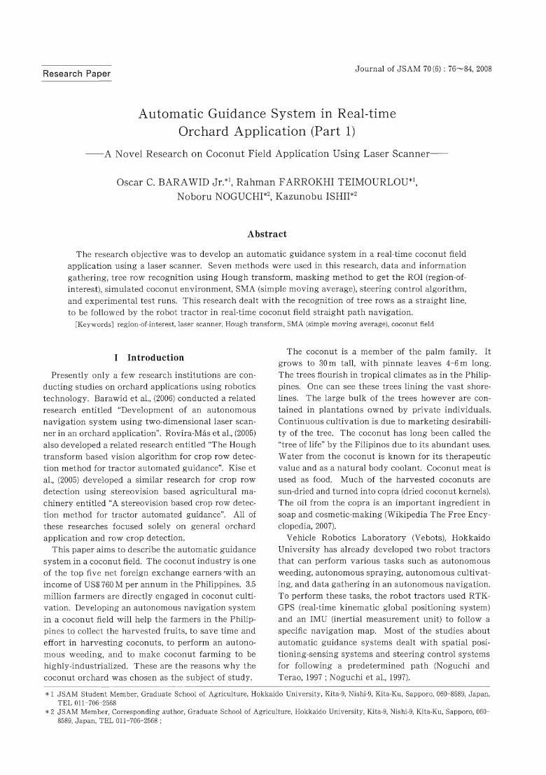
Fig. 1 Laser scanner attachment position on the
front of the robot tractor
shows the technical specification of the LMS SICK 291.
The laser scanner was attached to the front of the
robot tractor as shown in Fig. 1.
KUBOTA GL320 (24-kW) agricultural tractor was
used as the platform for this research that was
modified into a robot tractor. The robot tractor can
control steering, transmission (forward and neutral),
brake system, and three-point hitches (up and down).
For evaluation accuracy of the robot tractor in auton-
omous run, VRS-RTK-GPS (virtual reference station
real-time kinematic global positioning system) was
used as the positioning sensor to get the absolute
position of the vehicle in UTM (universal transverse
Mercator) coordinate system, and IMU (inertial meas-
urement unit) was used as the heading sensor to
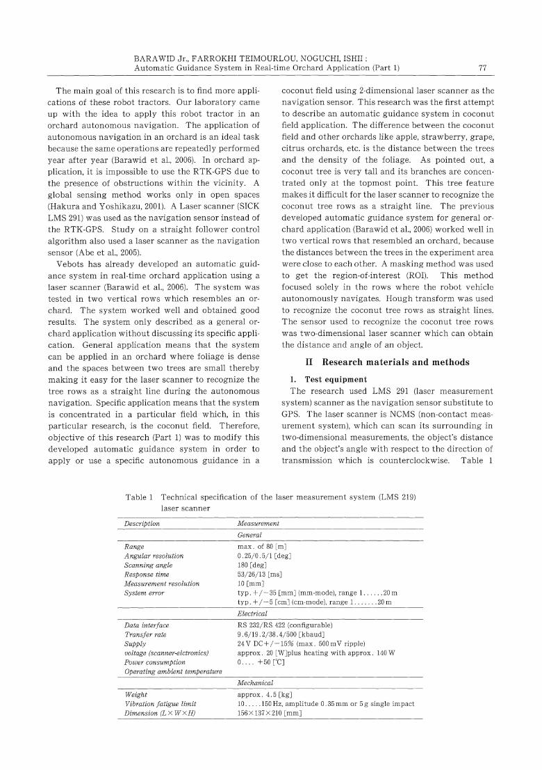
obtain the heading angle of the vehicle. Figure 2
shows the schematic diagram of the robot tractor and
its research components. All sensors are connected to
the laptop PC using RS-232 cable.
2. Data gathering
In Sapporo, Japan, there is no coconut field. It is
difficult to know the actual environment of coconut
field and difficult to conduct an experiment. Actual
coconut field experiment was conducted on March 17-21
, 2006 in Aurora, Philippines. The purpose of this
experiment was to obtain data from actual environ-
went of the coconut field and to test the developed
automatic guidance system for general orchard appli-
cation (Barawid et al., 2006) to see if the laser scanner
could recognize the coconut trees as a straight line.
The vehicle was run manually between coconut trees
and obtained data necessary for modification of the
automatic guidance system for general orchard appli-
cation into specific application that was the coconut
field. The laser scanner was attached on front of the
Fig. 2 Schematic diagram of the robot tractor and
its research components
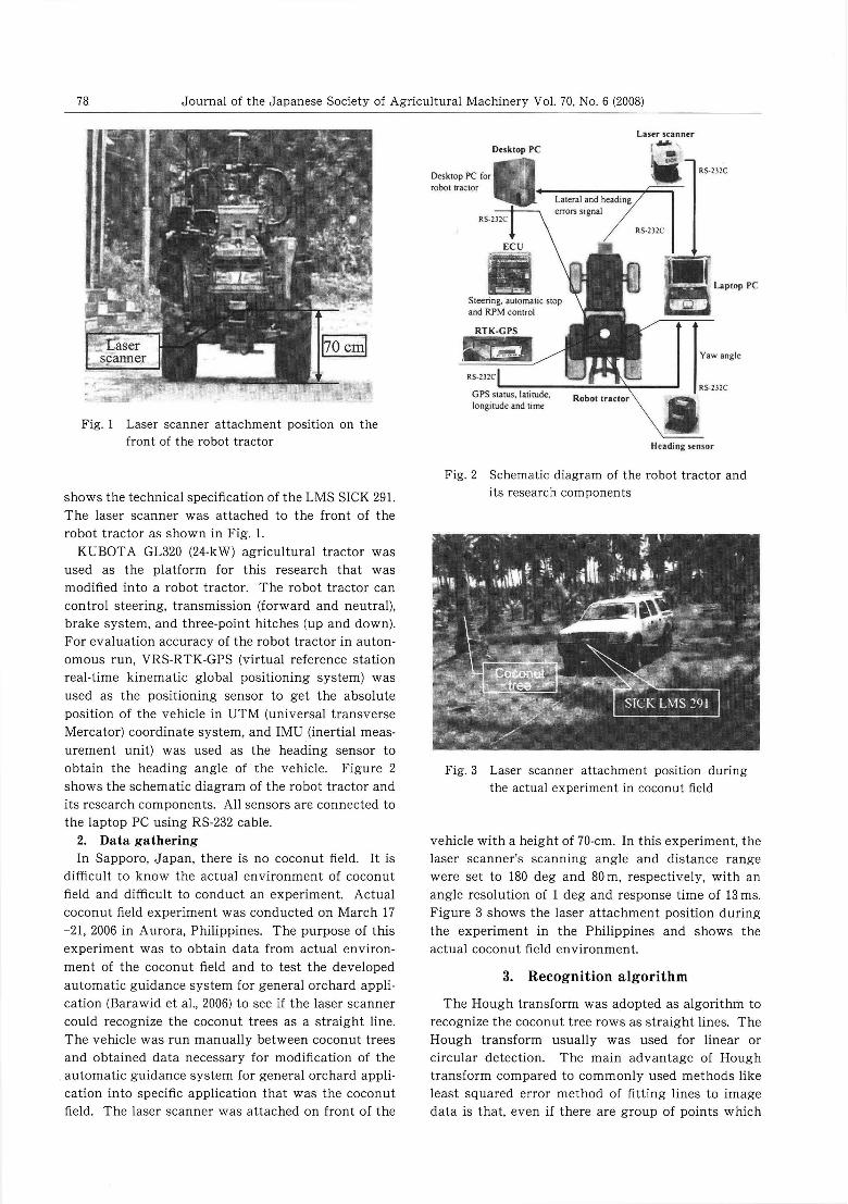
Fig. 3 Laser scanner attachment position during
the actual experiment in coconut field
vehicle with a height of 70-cm. In this experiment, the
laser scanner's scanning angle and distance range
were set to 180 deg and 80m, respectively, with an
angle resolution of 1 deg and response time of 13ms.
Figure 3 shows the laser attachment position during
the experiment in the Philippines and shows the
actual coconut field environment.
3. Recognition algorithm
The Hough transform was adopted as algorithm to
recognize the coconut tree rows as straight lines. The
Hough transform usually was used for linear or
circular detection. The main advantage of Hough
transform compared to commonly used methods like
least squared error method of fitting lines to image
data is that, even if there are group of points which
BARAWID Jr., FARROKHI TEIMOURLOU, NOGUCHI, ISHII:Automatic Guidance System in Real-time Orchard Application (Part1) 79
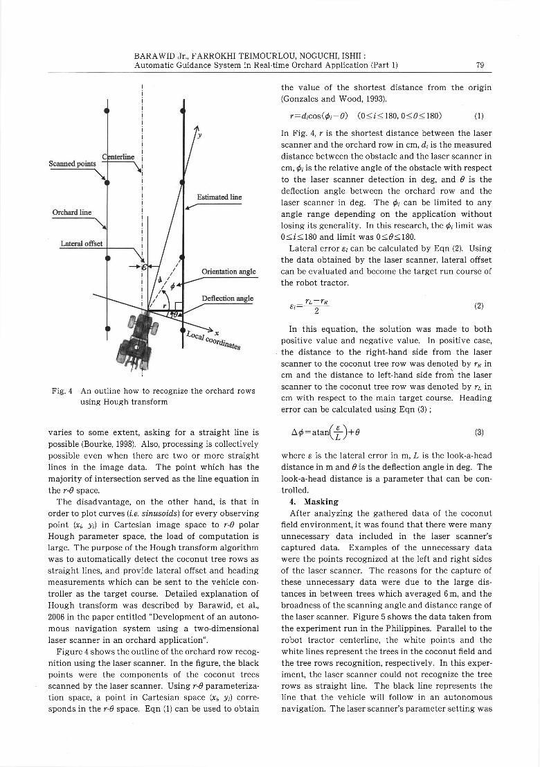
Fig. 4 An outline how to recognize the orchard rows
using Hough transform
varies to some extent, asking for a straight line is
possible (Bourke, 1998). Also, processing is collectively
possible even when there are two or more straight
lines in the image data. The point which has the
majority of intersection served as the line equation in
the r-θ space.
The disadvantage, on the other hand, is that in
order to plot curves (i. e. sinusoids) for every observing
point (xi,yi) in Cartesian image space to r-θ polar
Hough parameter space, the load of computation is
large. The purpose of the Hough transform algorithm
was to automatically detect the coconut tree rows as
straight lines, and provide lateral offset and heading
measurements which can be sent to the vehicle con-
troller as the target course. Detailed explanation of
Hough transform was described by Barawid, et al.,
2006 in the paper entitled "Development of an autono-
mous navigation system using a two-dimensional
laser scanner in an orchard application".
Figure 4 shows the outline of the orchard row recog-
nition using the laser scanner. In the figure, the black
points were the components of the coconut trees
scanned by the laser scanner. Using r-θ parameteriza-
tion space, a point in Cartesian space (xi,yi) corre-
sponds in the r-θ space. Eqn (1) can be used to obtain
the value of the shortest distance from the origin
(Gonzales and Wood, 1993).
r=dicos(φi-θ) (0〓i〓180, 0〓 θ〓180) (1)
In Fig. 4, r is the shortest distance between the laser
scanner and the orchard row in cm, di is the measured
distance between the obstacle and the laser scanner in
cm, φi is the relative angle of the obstacle with respect
to the laser scanner detection in deg, and θ is the
deflection angle between the orchard row and the
laser scanner in deg. The φi can be limited to any
angle range depending on the application without
losing its generality. In this research, the φi limit was
0〓i〓_180 and limit was 0〓 θ〓180.
Lateral error εl can be calcuiated by Eqn (2). Using
the data obtained by the laser scanner, lateral offset
can be evaluated and become the target run course of
the robot tractor.
(2)
In this equation, the solution was made to both
positive value and negative value. In positive case,
the distance to the right-hand side from the laser
scanner to the coconut tree row was denoted by rR in
cm and the distance to left-hand side from the laser
scanner to the coconut tree row was denoted by rL in
cm with respect to the main target course. Heading
error can be calculated using Eqn (3);
(3)
where ε is the lateral error in m, L is the look-a-head
distance in m and θ is the deflection angle in deg. The
look-a-head distance is a parameter that can be con-
trolled.
4. Masking
After analyzing the gathered data of the coconut
field environment, it was found that there were many
unnecessary data included in the laser scanner's
captured data. Examples of the unnecessary data
were the points recognized at the left and right sides
of the laser scanner. The reasons for the capture of
these unnecessary data were due to the large dis-
tances in between trees which averaged 6m, and the
broadness of the scanning angle and distance range of
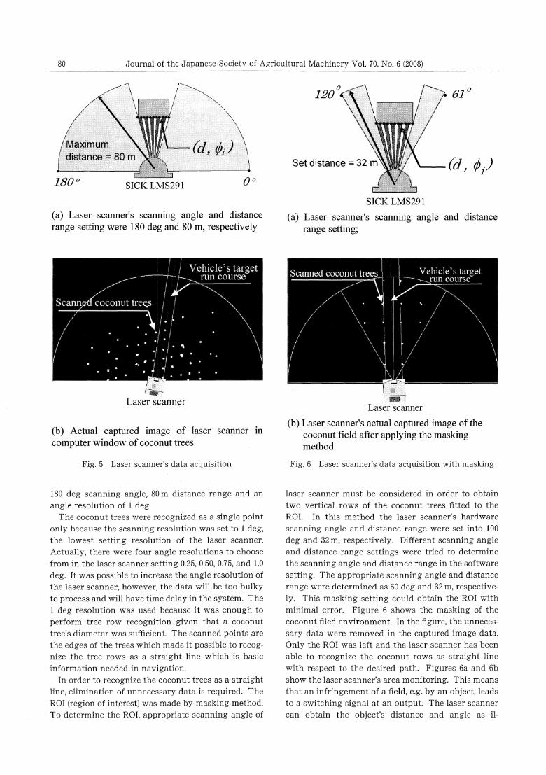
the laser scanner. Figure 5 shows the data taken from
the experiment run in the Philippines. Parallel to the
robot tractor centerline, the white points and the
white lines represent the trees in the coconut field and
the tree rows recognition, respectively. In this exper-
iment, the laser scanner could not recognize the tree
rows as straight line. The black line represents the
line that the vehicle will follow in an autonomous
navigation. The laser scanner's parameter setting was
80 Journal of the Japanese Society of Agricultural Machinery Vol. 70, No. 6 (2008)
(a) Laser scanner's scanning angle and distancerange setting were 180deg and 80m, respectively
(b) Actual captured image of laser scanner incomputer window of coconut trees
Fig. 5 Laser scanner's data acquisition
180deg scanning angle, 80m distance range and an
angle resolution of 1deg.
The coconut trees were recognized as a single point
only because the scanning resolution was set to 1deg,
the lowest setting resolution of the laser scanner.
Actually, there were four angle resolutions to choose
from in the laser scanner setting 0.25, 0.50, 0.75, and 1.0
deg. It was possible to increase the angle resolution of
the laser scanner, however, the data will be too bulky
to process and will have time delay in the system. The
1deg resolution was used because it was enough to
perform tree row recognition given that a coconuttree's diameter was sufficient. The scanned points are
the edges of the trees which made it possible to recog-
nize the tree rows as a straight line which is basic
information needed in navigation.
In order to recognize the coconut trees as a straight
line, elimination of unnecessary data is required. The
ROI (region-of-interest) was made by masking method.
To determine the ROI, appropriate scanning angle of
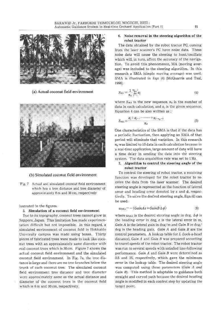
(a) Laser scanner's scanning angle and distancerange setting;
(b) Laser scanner's actual captured image of thecoconut field after applying the maskingmethod.
Fig. 6 Laser scanner's data acquisition with masking
laser scanner must be considered in order to obtain
two vertical rows of the coconut trees fitted to the
ROI. In this method the laser scanner's hardware
scanning angle and distance range were set into 100
deg and 32m, respectively. Different scanning angle
and distance range settings were tried to determine
the scanning angle and distance range in the software
setting. The appropriate scanning angle and distance
range were determined as 60deg and 32m, respective-
ly. This masking setting could obtain the ROI with
minimal error. Figure 6 shows the masking of the
coconut filed environment. In the figure, the unneces-
sary data were removed in the captured image data.
Only the ROI was left and the laser scanner has been
able to recognize the coconut rows as straight line
with respect to the desired path. Figures 6a and 6b
show the laser scanner's area monitoring. This means
that an infringement of a field, e. g. by an object, leads
to a switching signal at an output. The laser scanner
can obtain the object's distance and angle as il-
BARAWID Jr., FARROKHI TEIMOURLOU, NOGUCHI, ISHII:
Automatic Guidance System in Real-time Orchard Application (Part1) 81
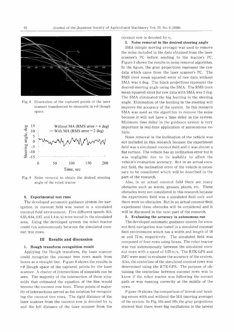
(a) Actual coconut field environment
(b) Simulated coconut field environment
Fig. 7 Actual and simulated coconut field environment
which has a tree distance and tree diameter of
approximately 6m and 30cm, respectively
lustrated in the figures.
5. Simulation of a coconut field environment
Due to its topography, coconut trees cannot grow in
Sapporo, Japan. This limitation has made experimen-
tation difficult but not impossible. In this regard, a
simulated environment of coconut field in Hokkaido
University campus was made using boxes. Thirty
pieces of fabricated trees were made to look like coco-
nut trees with an approximately same diameter with
real coconut trees which is 30cm. Figure 7 shows the
actual coconut field environment and the simulated
coconut field environment. In Fig. 7a, the tree dis-
tance is large and there are no tree branches below the
trunk of each coconut tree. The simulated coconut
field environment tree distance and tree diameter
were approximately same as the actual distance and
diameter of the coconut trees in the coconut field
which is 6m and 30cm, respectively.
6. Noise removal in the steering algorithm of the
robot tractor
The data obtained by the robot tractor PC, coming
from the laser scanner's PC have noise data. These
noise data will cause the steering to hunt/oscillate
which will, in turn, affect the accuracy of the naviga-
tion. To avoid this phenomenon, MA (moving aver-
age) was included to the steering algorithm. In this
research a SMA (simple moving average) was used.
SMA is illustrated in Eqn (4) (McQuarrie and Tsai,
1998).
(4)
where SMA is the new sequence, nd is the number of
data in each calculation, and aj is the given sequence.
Equation 4 can be also written as;
(5)
One characteristics of the SMA is that if the data has
a periodic fluctuation, then applying an SMA of that
period will eliminate that variation. In this research
nd was limited to 10 data in each calculation because in
a real-time application, large amount of data will have
a time delay in sending the data into the steering
system. The data acquisition rate was set to 1Hz.
7. Algorithm to control the steering angle of the
robot tractor
To control the steering of robot tractor, a receiving
function was developed for the robot tractor to re-
ceive the data from the laser scanner. The desired
steering angle is represented as the function of lateral
error and heading error denoted by ε and φ, respec-
tively. To solve the desired steering angle, Eqn (6) can
be used.
ωDSA=-(GainAε+GainBΔ φ) (6)
where ωDSA is the desired steering angle in deg, Δ φ is
the heading error in deg, ε is the lateral error in m,
Gain A is the lateral gain in deg/m and Gain B in deg/
deg is the heading gain. Gain A and Gain B are the
control parameters. A lookup table for L (look-a-head
distance), Gain A and Gain B was prepared according
to travel speeds of the robot tractor. The robot tractor
was run to several speeds with satisfied line-following
performance. Gain A and Gain B were determined as
0.5 and 35, respectively, which gave the minimum
error in the lookup table. The desired steering angle
was computed using these parameters (Gain A and
Gain B). This method is adaptable to guidance both
straight and curved path because the desired heading
angle is modified in each control step by updating the
target point.
82 Journal of the Japanese Society of Agricultural Machinery Vol. 70, No. 6 (2008)
Fig. 8 Illustration of the captured points of the laser
scanner transformed to sinusoids in r-θ Hough
space.
Fig. 9 Noise removal to obtain the desired steering
angle of the robot tractor
8. Experimental test runs
The developed automatic guidance system for nav-
igation in coconut field was tested in a simulated
coconut field environment. Five different speeds (0.5,
0.55, 0.64, 0.87, and 1.4m/s) were tested in the simulated
area. Using the developed system the robot tractor
could run autonomously between the simulated coco-
nut tree rows.
Ⅲ Results and discussion
1. Hough transform recognition result
Applying the Hough transform, the laser scanner
could recognize the coconut tree rows made from
boxes as a straight line. Figure 8 shows the results in
r-θ Hough space of the captured points by the laser
scanner. A cluster of intersections of sinusoids can be
seen. The majority of the intersection of these sinu-
soids that estimated the equation of the line would
become the coconut row lines. These points of major-
ity of intersections served as the solution for recogniz-
ing the coconut tree rows. The right distance of the
laser scanner from the coconut row is denoted by rR
and the left distance of the laser scanner from the
coconut row is denoted by rL.
2. Noise removal in the desired steering angle
SMA (simple moving average) was used to remove
the noise included in the data obtained from the laser
scanner's PC before sending to the tractor's PC.
Figure 9 shows the results in noise removal algorithm.
In the figure, the gray projections represent the raw
data which came from the laser scanner's PC. The
RMS (root mean squared) error of raw data without
SMA was 4deg. The black projections represent the
desired steering angle using the SMA. The RMS (root
mean squared) error for raw data with SMA was 2deg.
The SMA eliminated the big hunting in the steering
angle. Elimination of the hunting in the steering will
improve the accuracy of the system. In this research
SMA was used as the algorithm to remove the noise
because, it will not have a time delay in the system.
Minimum time delay in the guidance system is very
important in real-time application of autonomous ve-
hicle.
Noise removal in the inclination of the vehicle was
not included in this research because the experiment
field was a simulated coconut field and it was almost a
flat surface. The vehicle has an inclination error but it
was negligible due to its inability to affect the
vehicle's evaluation accuracy. But in an actual coco-
nut field, the inclination error of the vehicle is neces-
sary to be considered which will be described in the
part of the research.Also, in an actual coconut field there are many
obstacles such as weeds, grasses, plants, etc. These
obstacles were not considered in this research because
the experiment field was a simulated field only and
there were no obstacles. But in an actual coconut field
experiment these obstacles will be considered and it
will be discussed in the next part of the research.
3. Evaluating the accuracy in autonomous run
The developed automatic guidance system for coco-
nut field navigation was tested in a simulated coconut
field environment which has a width and length of 18
m and 72m, respectively. The simulated field was
composed of four rows using boxes. The robot tractor
was run autonomously between the simulated coco-
nut rows with a speed of 0.55m/s. The RTK-GPS and
IMU were used to evaluate the accuracy of the system.
Also, the centerline of the simulated coconut rows was
determined using the RTK-GPS. The purpose of ob-
taining the centerline between coconut rows was to
know if the robot tractor was following the correct
path or was running correctly at the middle of therows.
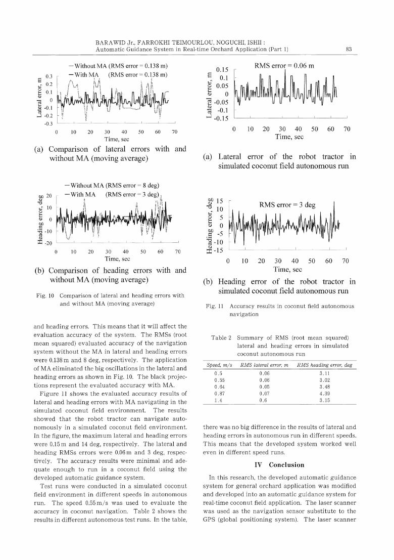
Figure 10 shows the comparison of lateral and head-
ing errors with and without the MA (moving average)
of the system. In Fig. 10a and 10b, the gray projections
showed that there were big oscillations in the lateral
BARAWID Jr., FARROKHI TEIMOURLOU, NOGUCHI, ISHII:
Automatic Guidance System in Real-time Orchard Application (Part 1) 83
(a) Comparison of lateral errors with andwithout MA (moving average)
(b) Comparison of heading errors with andwithout MA (moving average)
Fig. 10 Comparison of lateral and heading errors with
and without MA (moving average)
and heading errors. This means that it will affect the
evaluation accuracy of the system. The RMSs (root
mean squared) evaluated accuracy of the navigation
system without the MA in lateral and heading errors
were 0.138m and 8deg, respectively. The application
of MA eliminated the big oscillations in the lateral and
heading errors as shown in Fig. 10. The black projec-
tions represent the evaluated accuracy with MA.
Figure 11 shows the evaluated accuracy results of
lateral and heading errors with MA navigating in the
simulated coconut field environment. The results
showed that the robot tractor can navigate auto-
nomously in a simulated coconut field environment.
In the figure, the maximum lateral and heading errors
were 0.15m and 14deg, respectively. The lateral and
heading RMSs errors were 0.06m and 3deg, respec-
tively. The accuracy results were minimal and ade-
quate enough to run in a coconut field using thedeveloped automatic guidance system.
Test runs were conducted in a simulated coconut
field environment in different speeds in autonomous
run. The speed 0.55m/s was used to evaluate the
accuracy in coconut navigation. Table 2 shows the
results in different autonomous test runs. In the table,
(a) Lateral error of the robot tractor insimulated coconut field autonomous run
(b) Heading error of the robot tractor insimulated coconut field autonomous run
Fig. 11 Accuracy results in coconut field autonomous
navigation
Table 2 Summary of RMS (root mean squared)
lateral and heading errors in simulated
coconut autonomous run
there was no big difference in the results of lateral and
heading errors in autonomous run in different speeds.
This means that the developed system worked well
even in different speed runs.
Ⅳ Conclusion
In this research, the developed automatic guidance
system for general orchard application was modified
and developed into an automatic guidance system for
real-time coconut field application. The laser scanner
was used as the navigation sensor substitute to the
GPS (global positioning system). The laser scanner
84 Journal of the Japanese Society of Agricultural Machinery Vol. 70, No. 6 (2008)
obtained the data necessary for orchard path naviga-
tion such as the object's distance and object's angle.
An actual experiment was conducted in the Philip-
pines to obtain the data necessary for modifying thedeveloped automatic guidance system. The research
used a masking method to obtain the ROI (region-of-
interest) in the data obtained by the laser scanner.
The evaluated accuracy of the automatic guidance
system for lateral and heading errors were 0.06m and
3deg, respectively. These results were adequate enough
to navigate the robot tractor in real-time coconut field
application. The developed system was evaluated at
0.55m/s speed.
The future works of the research are (1) to test
experimental runs in an actual coconut field or appli-
cation in different orchards such as citrus, apple,
strawberry, banana, etc.; (2) to make a turning algo-
rithm for autonomous navigation in an orchard; and
(3) to develop a low cost and small scale robot vehiclethat can navigate in any given orchard application
because the vehicle platform used in this research
were expensive and quite big.
Acknowledgement
The author wishes to acknowledge the Japanese
Ministry of Education, Culture, Sports, Science, and
Technology for providing a scholarship grant to con-
duct a research in Hokkaido University, Sapporo,
Japan about the automatic guidance system using
robot tractors.
References
Abe, G., Mizushima, A., Noguchi N. (2005). Study on a straight
follower control algorithm based on a laser scanner. Journal
of the JSAM, 67 (3), 65-71.
Barawid, O. C. Jr., Ishii, K., Noguchi N. (2006). Development of an
autonomous navigation system using two-dimensional laser
scanner in an orchard application. Biosystems Engineering,
doi: 10.1016/j.biosystemseng.
Bourke, P. (1998). Auto-regression Analysis (AR). http://local.
wasp.uwa.edu.au/pbourkke/other/ar/(August11,2006)
Gonzales, R. C., Woods, R. E. (1993). Digital Image Processing.
Addisoon-Wesley Publishing, USA.
Hakura, J., Yoshikazu, A. (2001). Self-localization based on ego
motion detection using optic flow. Proceedings of the Fourth
IFAC Symposium on Intelligent Autonomous Vehicle, pp.
320-331.
Kise, M., Noguchi, N., Ishii, K., Terao, H. (2001). Development of
the agricultural autonomous tractor with an RTK-GPS and
FOG. Proceedings of the Fourth IFAC Symposium on Intelli-
gent Autonomous Vehicle, 103-108.
McQuarrie, A., Tsai, C. L. (1998). Regression and Time Series Model
Selection. World Scientific, Singapore.
Noguchi, N., Terao, H. (1997). Path planning of an agricultural
mobile robot by neural network and genetic algorithm.
Biosystems Engineering, 18, 187-204.
Noguchi, N., Ishii, K., Terao, H. (1997). Development of anagricul-
tural mobile robot using a geomagnetic direction sensor and
image sensors. Journal of Agricultural Engineering, 67, 1-15.
Rovira-Mas, F., Zhang, Q., Reid, J. F., Will, J. D. (2005). Hough-
transform-based vision algorithm for crop row detection of
an automated agricultural vehicle. Journal of Automobile
Engineering, 219(8), 999-1010.
Wikipedia, The Free Encyclopedia (2007). http://en.wikipedia.
org/wiki/Coconut_trees(March16,2007).
(Received: 14 November. 2007・Question time limit: 31 January. 2009)
「研 究 論 文 」
果 樹 園作 業 の た め の 自動 走 行 シス テ ム(第1報)-レ ー ザ ス キ ャ ナ を用 い た シ ス テ ム の コ コ ナ ッ ツ園 へ の
適 用-
バ ラ ウ ィ ッ ド オ ス カ ー ジ ュ ニ ア*1・ フ ァ ロイ テ イ モ ロ
ウ ラー マ ン*1・ 野 口 伸*2・ 石 井 一 暢*2
要 旨
コ コ ナ ッ ツ園 に お け る作 業 を想 定 して,レ ー ザ ス キ ャ
ナ を 航 法 セ ンサ と した 自動 走 行 シ ス テ ム の 開 発 を研 究 の
目的 と した。本 研 究 で は,自 動 走 行 シス テ ムを 開 発 す る上
で7つ の プ ロ セ ス が 採 用 さ れ た 。 レー ザ ー ス キ ャナ に よ
るデ ー タ取 得 ・処 理,ハ ブ変 換 に よ る樹 列 認 識 取 得 され
た距 離 空 間情 報 の マ ス キ ン グ処 理,擬 似 的 コ コ ナ ツ園 に
お け る試 験,ナ ビゲ ー シ ョ ン シ グ ナル の ノ イ ズ 除 去 の た
め の 移 動 平 均 処 理,操 舵 制 御 ア ル ゴ リズ ム お よ び 自動 走
行 試 験 で あ る。また,採 用 した ハ ブ変 換 は樹 列 を 直線 と し
て認 識 ・処 理 し,車 両 は そ の認 識 され た 直 線 を走 行 す る
よ うに操 舵 制 御 した。
[キーワー ド] (ROI) region-of-interest, 2次元 レーザスキャナ,
ハブ変換,最 小二乗法,単 純移動変換,コ コナツ園
*1 学 生会 員,北 海 道大 学大 学院 農学 研究科(〒060-8589 札 幌市北
区 北9条 西9丁 目 TEL 011-706-2568)
*2 会 員,北 海 道大 学大 学院 農学 研究 科(〒060-8589 札 幌市北 区北
9条 西9丁 目 TEL 011-706-3847)