Embed Size (px)
Citation preview
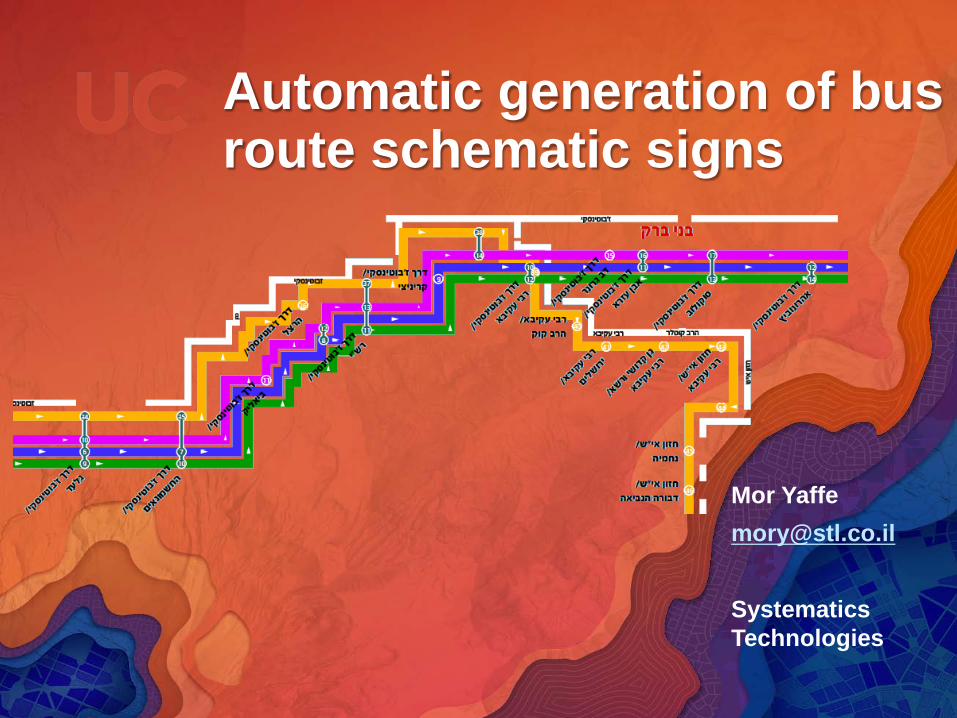
Automatic generation of bus route schematic signs
Systematics Technologies
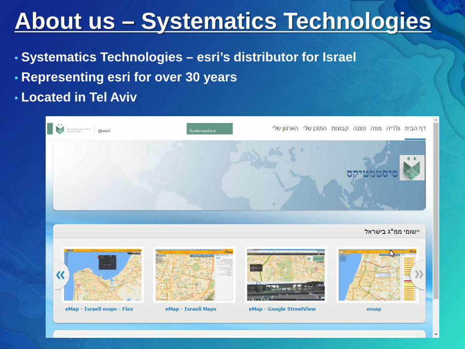
About us – Systematics Technologies• Systematics Technologies – esri’s distributor for Israel• Representing esri for over 30 years• Located in Tel Aviv
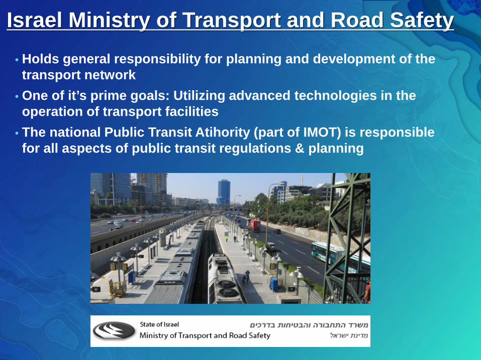
Israel Ministry of Transport and Road Safety• Holds general responsibility for planning and development of the transport network
• One of it’s prime goals: Utilizing advanced technologies in the operation of transport facilities
• The national Public Transit Atihority (part of IMOT) is responsible for all aspects of public transit regulations & planning
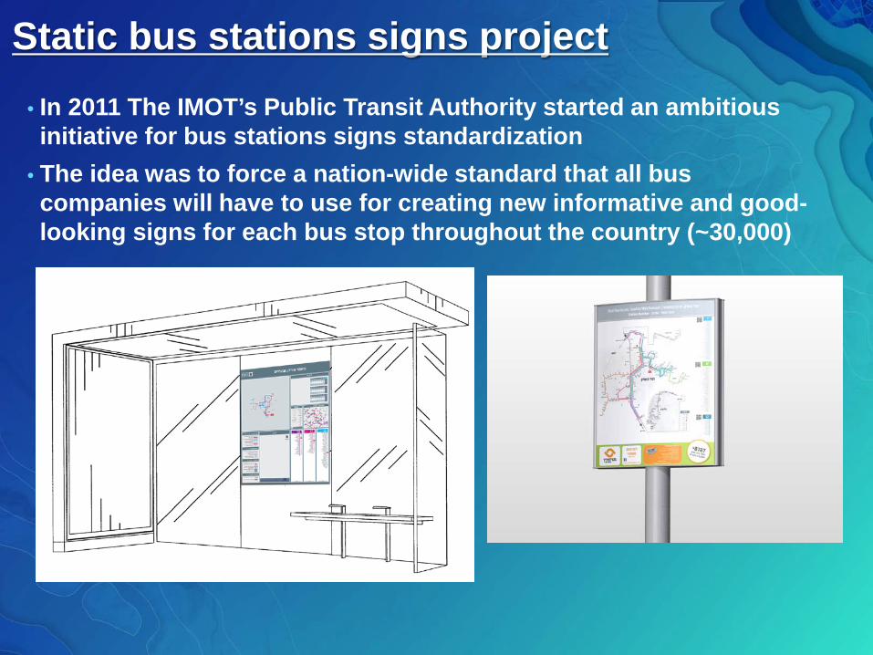
Static bus stations signs project• In 2011 The IMOT’s Public Transit Authority started an ambitious initiative for bus stations signs standardization
• The idea was to force a nation-wide standard that all bus companies will have to use for creating new informative and good-looking signs for each bus stop throughout the country (~30,000)
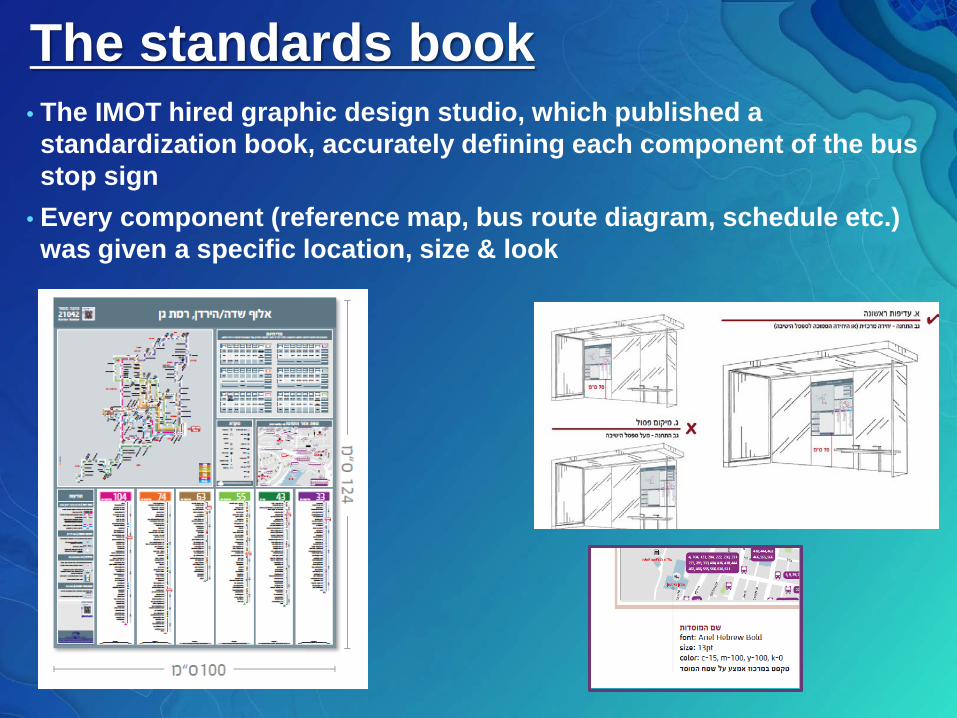
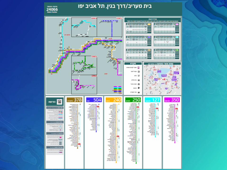
The standards book• The IMOT hired graphic design studio, which published a standardization book, accurately defining each component of the bus stop sign
• Every component (reference map, bus route diagram, schedule etc.) was given a specific location, size & look
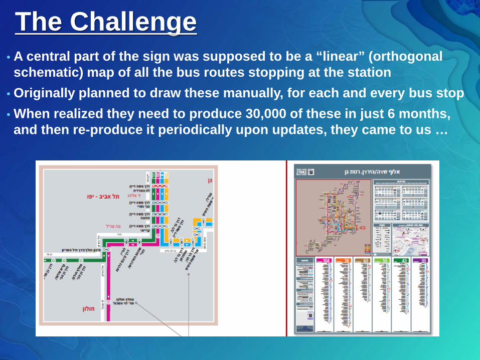
The Challenge• A central part of the sign was supposed to be a “linear” (orthogonal schematic) map of all the bus routes stopping at the station
• Originally planned to draw these manually, for each and every bus stop• When realized they need to produce 30,000 of these in just 6 months, and then re-produce it periodically upon updates, they came to us …
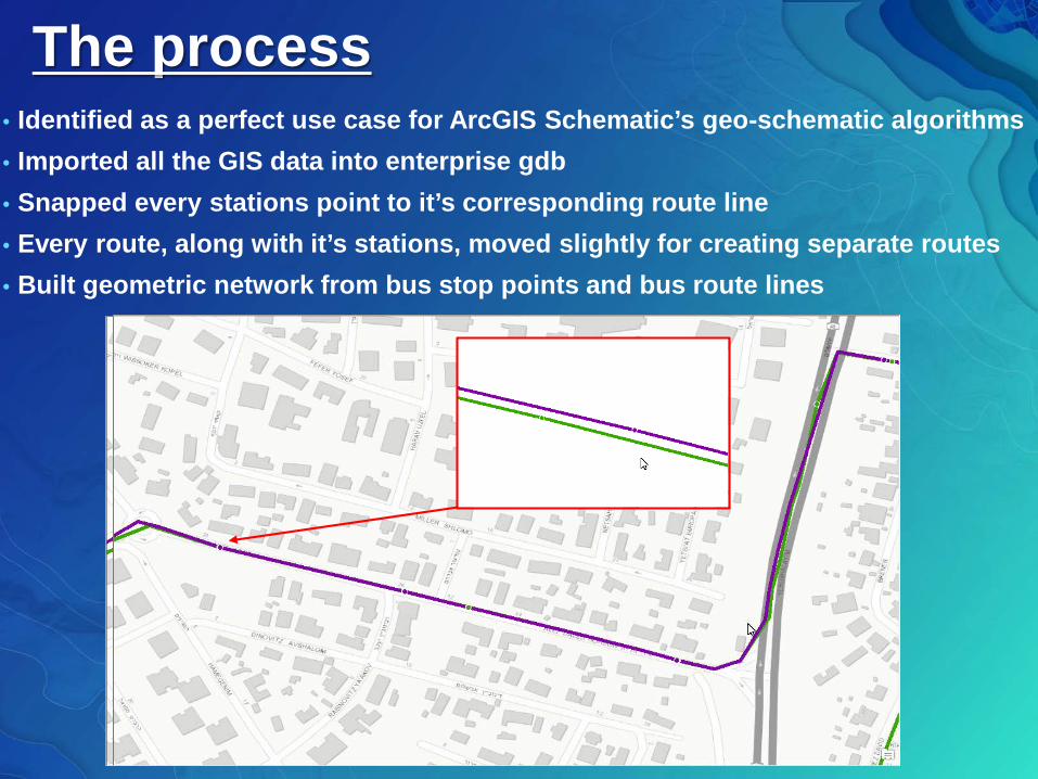
The process• Identified as a perfect use case for ArcGIS Schematic’s geo-schematic algorithms• Imported all the GIS data into enterprise gdb• Snapped every stations point to it’s corresponding route line• Every route, along with it’s stations, moved slightly for creating separate routes• Built geometric network from bus stop points and bus route lines
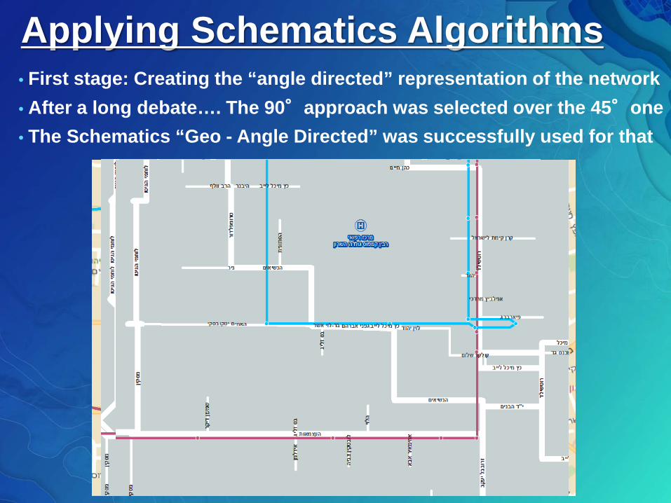
Applying Schematics Algorithms• First stage: Creating the “angle directed” representation of the network• After a long debate…. The 90°approach was selected over the 45°one• The Schematics “Geo - Angle Directed” was successfully used for that
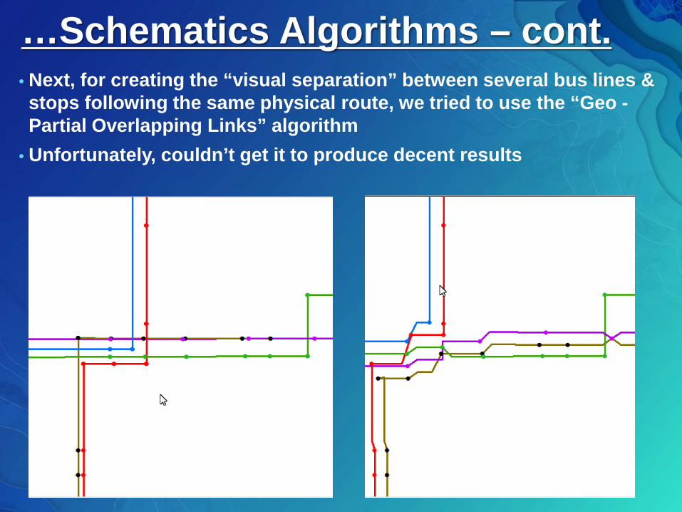
…Schematics Algorithms – cont.• Next, for creating the “visual separation” between several bus lines & stops following the same physical route, we tried to use the “Geo -Partial Overlapping Links” algorithm
• Unfortunately, couldn’t get it to produce decent results
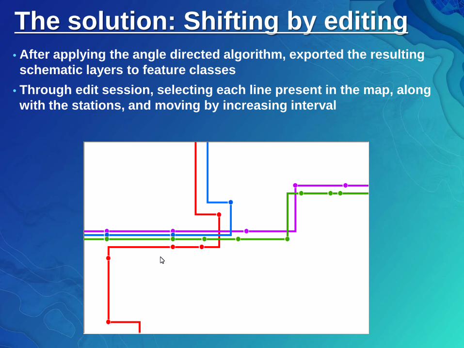
The solution: Shifting by editing• After applying the angle directed algorithm, exported the resulting schematic layers to feature classes
• Through edit session, selecting each line present in the map, along with the stations, and moving by increasing interval
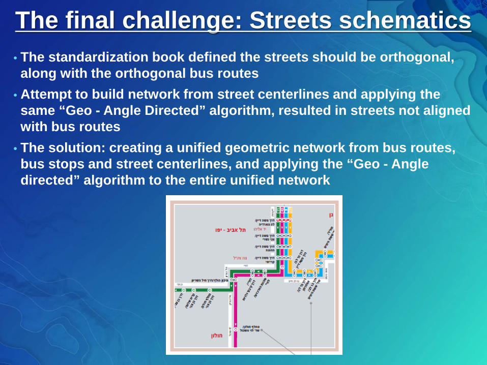
The final challenge: Streets schematics• The standardization book defined the streets should be orthogonal, along with the orthogonal bus routes
• Attempt to build network from street centerlines and applying the same “Geo - Angle Directed” algorithm, resulted in streets not aligned with bus routes
• The solution: creating a unified geometric network from bus routes, bus stops and street centerlines, and applying the “Geo - Angle directed” algorithm to the entire unified network
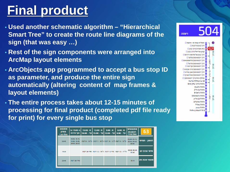
Final product• Used another schematic algorithm – “Hierarchical Smart Tree” to create the route line diagrams of the sign (that was easy …)
• Rest of the sign components were arranged into ArcMap layout elements
• ArcObjects app programmed to accept a bus stop ID as parameter, and produce the entire sign automatically (altering content of map frames & layout elements)
• The entire process takes about 12-15 minutes of processing for final product (completed pdf file ready for print) for every single bus stop
Lessons learned & Conclusion• The IMOT approached us only for the linear map component, but eventually, ArcMap’s API enabled the automation of the entire sign
• The only schematic algorithm which was actually used for the linear map is “Angle Directed”, but it saved 100s of hours of manual drawing
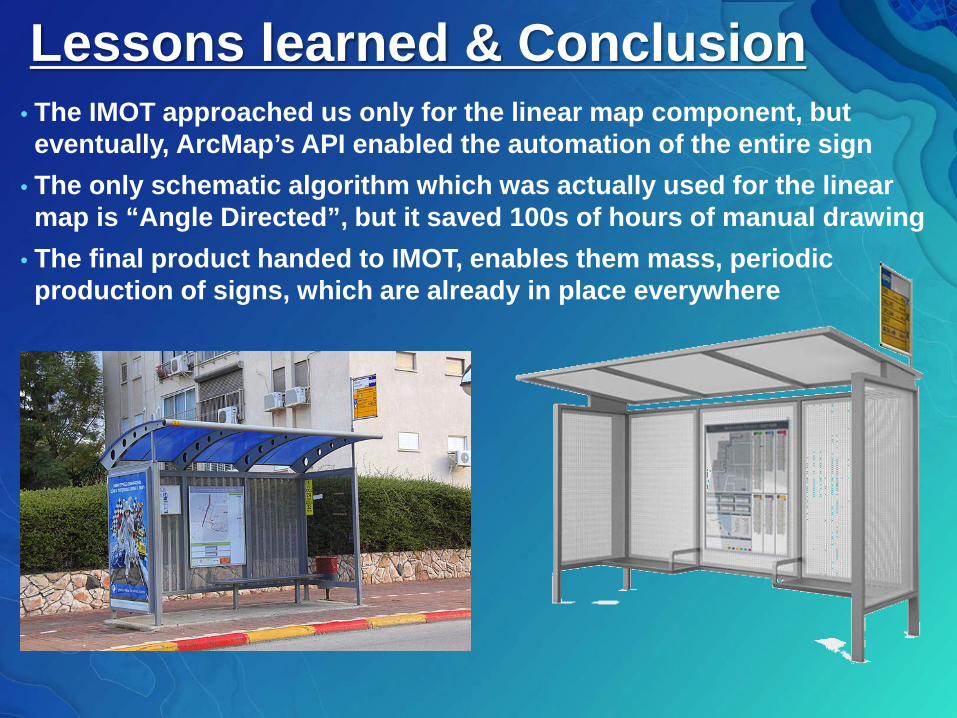
• The final product handed to IMOT, enables them mass, periodic production of signs, which are already in place everywhere