Embed Size (px)
Citation preview
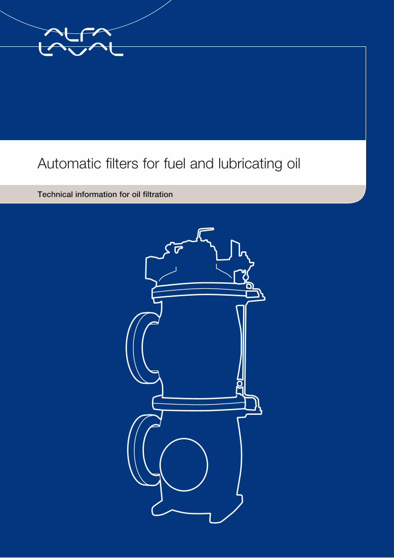
Technical information for oil filtration
Automatic filters for fuel and lubricating oil

Inside view
3 Summary
4 Background
5 Filtration theory
11 The Alfa Laval filter
14 Innovations Automatic filter with integrated centrifuge Fuel oil filter – F-152 range Lube oil filter – 350 range
20 Lubricating oil filtration
24 Fuel oil filtration
This technical handbook provides an insight into filtration technology in general and the Alfa Laval automatic filters in particular.
Alfa Laval automatic filters
4
Alfa Laval automatic filters
4
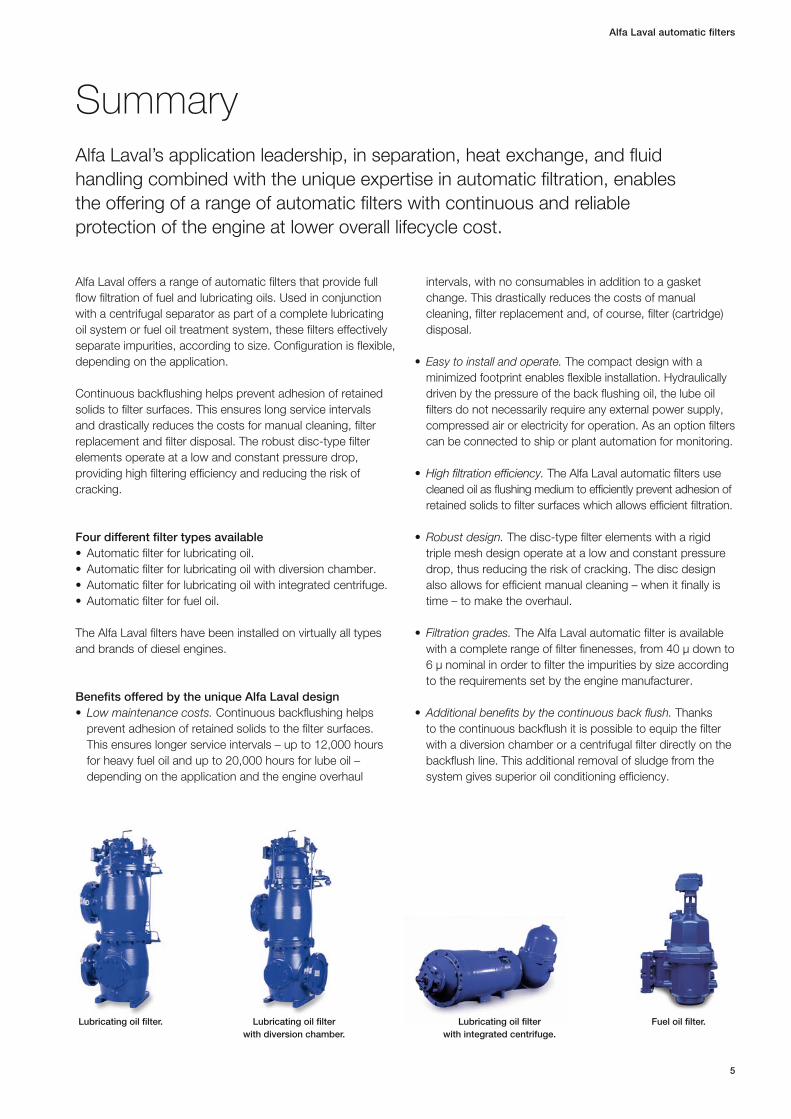
SummaryAlfa Laval’s application leadership, in separation, heat exchange, and fluid handling combined with the unique expertise in automatic filtration, enables the offering of a range of automatic filters with continuous and reliable protection of the engine at lower overall lifecycle cost.
Alfa Laval offers a range of automatic filters that provide full flow filtration of fuel and lubricating oils. Used in conjunction with a centrifugal separator as part of a complete lubricating oil system or fuel oil treatment system, these filters effectively separate impurities, according to size. Configuration is flexible, depending on the application.
Continuous backflushing helps prevent adhesion of retained solids to filter surfaces. This ensures long service intervals and drastically reduces the costs for manual cleaning, filter replace ment and filter disposal. The robust disc-type filter elements operate at a low and constant pressure drop, providing high filtering efficiency and reducing the risk of cracking .
Four different filter types available• Automaticfilterforlubricatingoil.• Automaticfilterforlubricatingoilwithdiversionchamber.• Automaticfilterforlubricatingoilwithintegratedcentrifuge.• Automaticfilterforfueloil.
The Alfa Laval filters have been installed on virtually all types and brands of diesel engines.
Benefits offered by the unique Alfa Laval design• Low maintenance costs. Continuous backflushing helps
prevent adhesion of retained solids to the filter surfaces. This ensures longer service intervals – up to 12,000 hours for heavy fuel oil and up to 20,000 hours for lube oil – depending on the application and the engine overhaul
intervals , with no consumables in addition to a gasket change. This drastically reduces the costs of manual cleaning, filter replacement and, of course, filter (cartridge) disposal.
• Easy to install and operate. The compact design with a minimized footprint enables flexible installation. Hydraulically driven by the pressure of the back flushing oil, the lube oil filters do not necessarily require any external power supply, compressed air or electricity for operation. As an option filters can be connected to ship or plant automation for monitoring.
•High filtration efficiency. The Alfa Laval automatic filters use cleaned oil as flushing medium to efficiently prevent adhesion of retained solids to filter surfaces which allows efficient filtration.
•Robust design. The disc-type filter elements with a rigid triple mesh design operate at a low and constant pressure drop, thus reducing the risk of cracking. The disc design also allows for efficient manual cleaning – when it finally is time – to make the overhaul.
• Filtration grades. The Alfa Laval automatic filter is available with a complete range of filter finenesses, from 40 μ down to 6 μ nominal in order to filter the impurities by size according to the requirements set by the engine manufacturer.
•Additional benefits by the continuous back flush. Thanks to the continuous backflush it is possible to equip the filter with a diversion chamber or a centrifugal filter directly on the backflush line. This additional removal of sludge from the system gives superior oil conditioning efficiency.
5
Alfa Laval automatic filters
Lubricating oil filter. Lubricating oil filter with diversion chamber.
Lubricating oil filter with integrated centrifuge.
Fuel oil filter.
Alfa Laval automatic filters
6
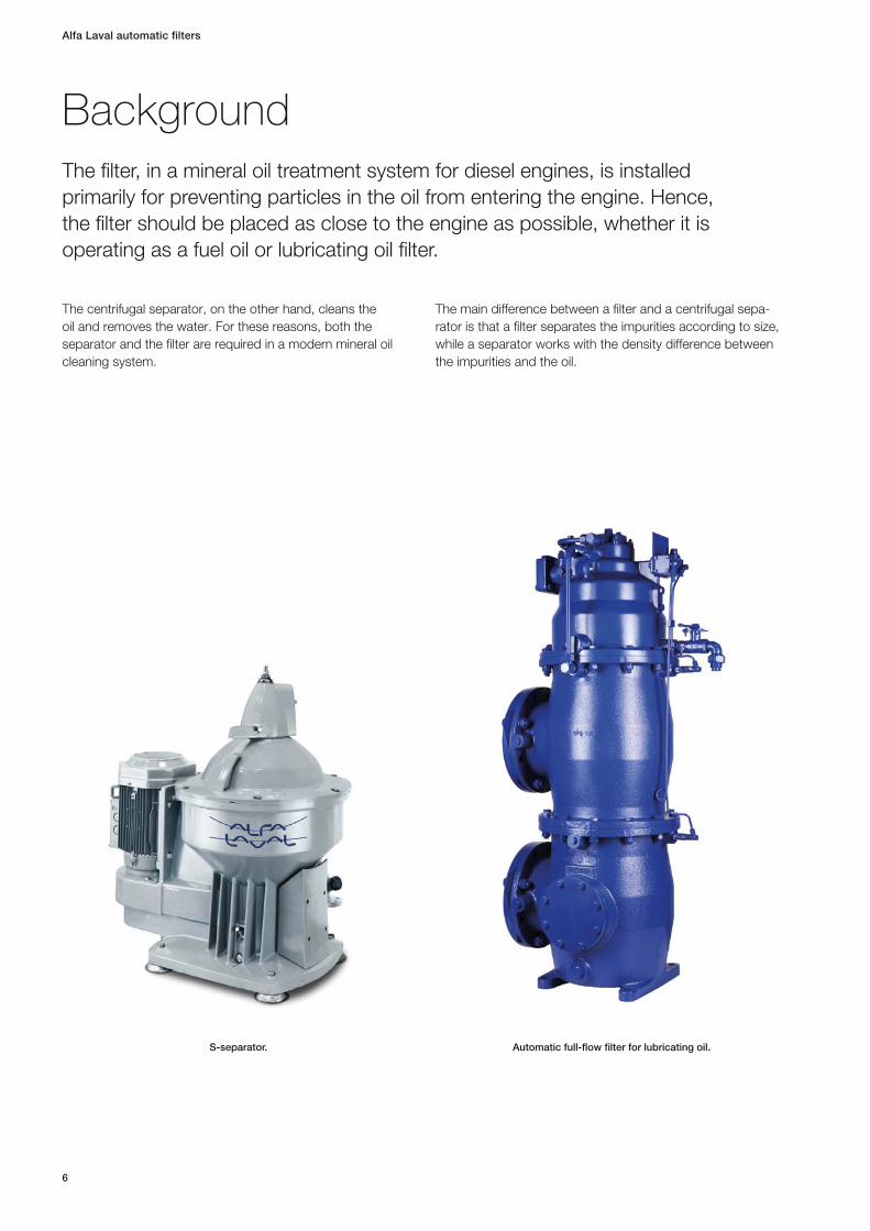
BackgroundThe filter, in a mineral oil treatment system for diesel engines, is installed primarily for preventing particles in the oil from entering the engine. Hence, the filter should be placed as close to the engine as possible, whether it is operating as a fuel oil or lubricating oil filter.
The centrifugal separator, on the other hand, cleans the oil and removes the water. For these reasons, both the separator and the filter are required in a modern mineral oil cleaning system.
The main difference between a filter and a centrifugal sepa-rator is that a filter separates the impurities according to size, while a separator works with the density difference between the impurities and the oil.
Automatic full-flow filter for lubricating oil.S-separator.

Filtration theoryFiltration can be defined as the process of collecting solid particles from a fluid by passing the fluid through a filter medium (which could be a filter screen or a paper element) where the particles are retained.
Two basic methods of filtration are used:1. Surface filtration, used in strainers and cake filters.2. Deep-bed filtration, used in depth filters.
The principles of particle collection in surface filtration and deep-bed filtration are entirely different.
In surface filtration the particles are collected on the surface of the filter medium, whereby a filter cake of retained particles is created. This cake can be removed by back-flushing the filter.
In deep-bed filtration the particles pass through a filter and are collected inside the filter. Since different capture mechanisms are used in surface filtration and deep-bed filtration , the value of comparing filter finenesses of the two types is questionable.
Figure 2 shows the different mechanisms operating in surface filtration and deep-bed filtration, respectively.
As the solid particles accumulate in a depth filter, the pressure drop increases during filtration. When the pressure drop reaches a certain level, the filter elements must be replaced.
Figure 3 shows examples of filter screen configurations used on surface filters.
7
Alfa Laval automatic filters
Fluid with solid particles
Filtrated �uid (�ltrate)
Filter medium
Figure 1. Schematic diagram of a filtration system.
Fluid
Cake of captured particlesFilter medium Filter medium
Deep-bed filtrationSurface filtration
Fluid
Figure 2. Principles of surface and deep-bed filtration.
Figure 3. Examples of filter cloths.
A B C D E F
Due to the different screen configurations, comparisons of given filter finenesses on different filter screens with one another are of doubtful value.
The advantage of using a surface filter, rather than a depth filter, is that the filter screens can be cleaned, thus the filter can be reused. If the filter is backflushed continuously, the pressure drop across the filter will remain constant.
In practice, a filter can be retained in operation without interruption , provided that the backflushing is a part of the filter construction. If so, the filter is called automatic back-flushing, or just automatic.
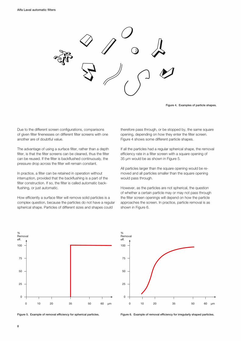
How efficiently a surface filter will remove solid particles is a complex question, because the particles do not have a regular spherical shape. Particles of different sizes and shapes could
therefore pass through, or be stopped by, the same square opening, depending on how they enter the filter screen. Figure 4 shows some different particle shapes.
If all the particles had a regular spherical shape, the removal efficiency rate in a filter screen with a square opening of 35 µm would be as shown in Figure 5.
All particles larger than the square opening would be re-moved and all particles smaller than the square opening would pass through.
However, as the particles are not spherical, the question of whether a certain particle may or may not pass through the filter screen openings will depend on how the particle approaches the screen. In practice, particle removal is as shown in Figure 6.
Alfa Laval automatic filters
8
Figure 4. Examples of particle shapes.
%Removaleff.
100
75
50
25
100 20 50 60 μm
0
35 μm
%Removaleff.
100
75
50
25
100 20 50 60
0
35
Figure 5. Example of removal efficiency for spherical particles. Figure 6. Example of removal efficiency for irregularly shaped particles.
Consequently, some particles larger than the square opening will pass through, and some particles smaller than the square opening will not.
When comparing surface filters, it is important to specify the size of the square opening being used. Since particles have irregular shapes, their ability to pass or not pass through the filter depends on whether they arrive at the filter screen with their small end first, or broadside. The term “nominal filter fineness ” has therefore been applied to surface filters.
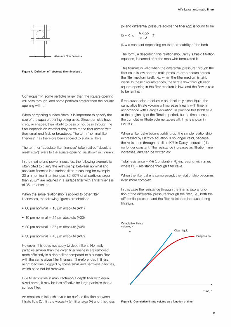
The term for “absolute filter fineness” (often called “absolute mesh size”) refers to the square opening, as shown in Figure 7.
In the marine and power industries, the following example is often cited to clarify the relationship between nominal and absolute fineness in a surface filter, measuring for example 20 µm nominal filter fineness: 85–90% of all particles larger than 20 µm are retained in a surface filter with a filter fineness of 35 µm absolute.
When the same relationship is applied to other filter finenesses , the following figures are obtained:
• 06µmnominal→ 10 µm absolute (A01)
• 10µmnominal→ 25 µm absolute (A03)
• 20µmnominal→ 35 µm absolute (A05)
• 30µmnominal→ 45 µm absolute (A07)
However, this does not apply to depth filters. Normally, particles smaller than the given filter fineness are removed more efficiently in a depth filter compared to a surface filter with the same given filter fineness. Therefore, depth filters might become clogged by these small and harmless particles, which need not be removed.
Due to difficulties in manufacturing a depth filter with equal sized pores, it may be less effective for large particles than a surface filter.
An empirical relationship valid for surface filtration between filtrate flow (Q), filtrate viscosity (n), filter area (A) and thickness
(d) and differential pressure across the filter (∆p) is found to be
Q = K x A x ∆p
(1)
u x d
(K = a constant depending on the permeability of the bed)
The formula describing this relationship, Darcy’s basic filtration equation, is named after the man who formulated it.
This formula is valid when the differential pressure through the filter cake is low and the main pressure drop occurs across the filter medium itself, i.e., when the filter medium is fairly clean. In these circumstances, the filtrate flow through each square opening in the filter medium is low, and the flow is said to be laminar.
If the suspension medium is an absolutely clean liquid, the cumulative filtrate volume will increase linearly with time, in accordance with Darcy’s equation. In practice this holds true at the beginning of the filtration period, but as time passes, the cumulative filtrate volume tapers off. This is shown in Figure 8.
When a filter cake begins building up, the simple relationship expressed by Darcy’s equation is no longer valid, because the resistance through the filter (K/d in Darcy’s equation) is no longer constant. The resistance increases as filtration time increases, and can be written as:
Total resistance = K/d (constant) + Rc (increasing with time), where Rc = resistance through filter cake.
When the filter cake is compressed, the relationship becomes even more complex.
In this case the resistance through the filter is also a func-tion of the differential pressure through the filter, i.e., both the differential pressure and the filter resistance increase during filtration.
9
Alfa Laval automatic filters
Absolute �lter �neness
Time, t
Cumulative �ltratevolume, V
Clean liquid
Suspension
Figure 8. Cumulative filtrate volume as a function of time.
Figure 7. Definition of “absolute filter fineness”.

Alfa Laval automatic filters
10
Figure 9. Automatic lubricating oil filter with diversion chamber.
Unfiltered oil
Filtered oilto engine
Filtered oil
Unfiltered oil
Filtered oil
To lubricating oil sump
Hydraulic motor
Drain cockFiltered oil to
hydraulic motor
Distributor
Strainer
Full-flow chamber
Diversion chamber
11
Alfa Laval automatic filters
DesignThe Alfa Laval filter consists of: • Thefilterhousing.• Thefilteringunitanddistributor.• Thehydraulicmotor.
The filter housing for the automatic filter can have one or two chambers. The first chamber, where the cleaning of the oil occurs, is called the full-flow chamber. The second chamber, where the impurities stopped by the full-flow chamber are collected , is called the diversion chamber. Cross-sections of the filter with diversion chamber are shown in Figure 9.
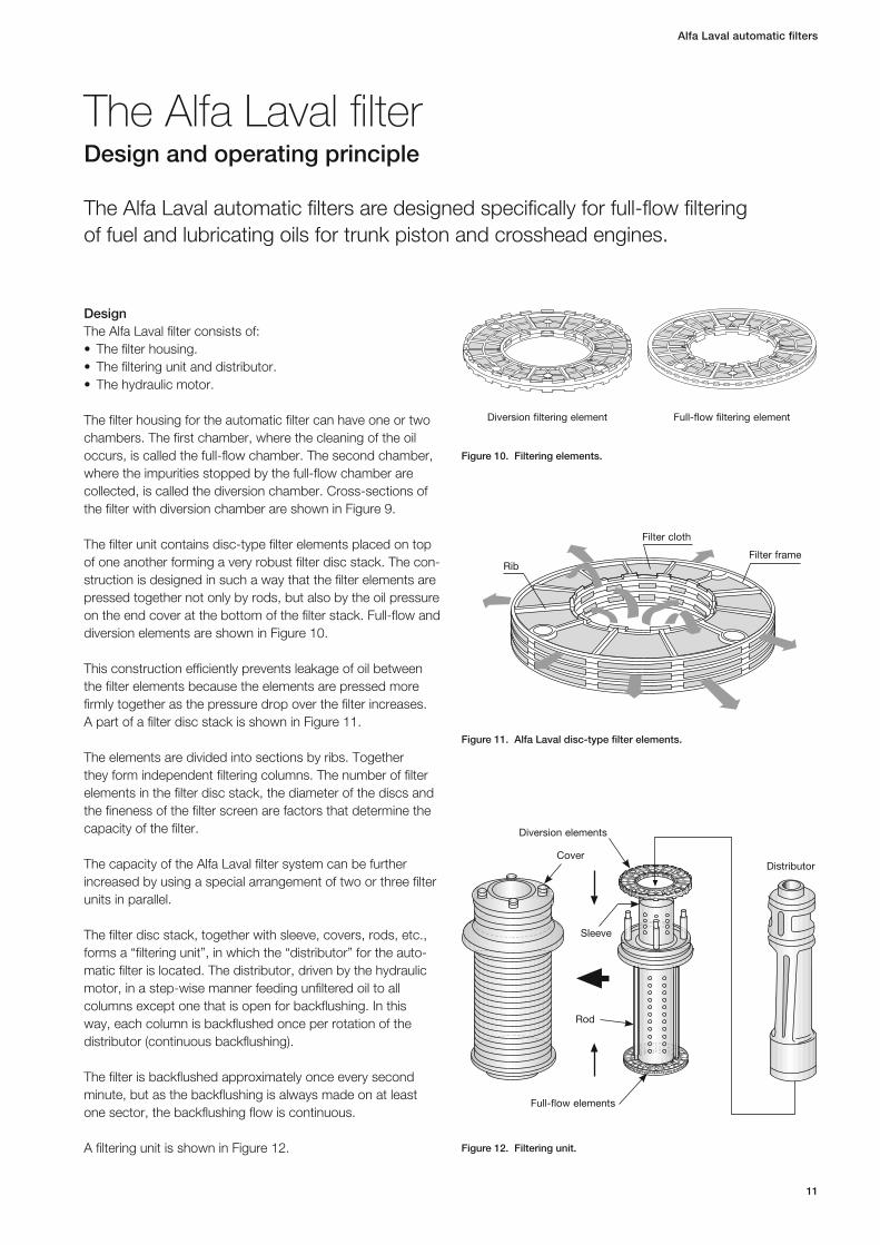
The filter unit contains disc-type filter elements placed on top of one another forming a very robust filter disc stack. The con-struction is designed in such a way that the filter elements are pressed together not only by rods, but also by the oil pressure on the end cover at the bottom of the filter stack. Full-flow and diversion elements are shown in Figure 10.
This construction efficiently prevents leakage of oil between the filter elements because the elements are pressed more firmly together as the pressure drop over the filter increases. A part of a filter disc stack is shown in Figure 11.
The elements are divided into sections by ribs. Together they form independent filtering columns. The number of filter elements in the filter disc stack, the diameter of the discs and the fineness of the filter screen are factors that determine the capacity of the filter.
The capacity of the Alfa Laval filter system can be further increased by using a special arrangement of two or three filter units in parallel.
The filter disc stack, together with sleeve, covers, rods, etc., forms a “filtering unit”, in which the “distributor” for the auto-matic filter is located. The distributor, driven by the hydraulic motor, in a step-wise manner feeding unfiltered oil to all columns except one that is open for backflushing. In this way, each column is backflushed once per rotation of the distributor (continuous backflushing).
The filter is backflushed approximately once every second minute, but as the backflushing is always made on at least one sector, the backflushing flow is continuous.
A filtering unit is shown in Figure 12.
The Alfa Laval filterDesign and operating principle
The Alfa Laval automatic filters are designed specifically for full-flow filtering of fuel and lubricating oils for trunk piston and crosshead engines.
Full-flow filtering elementDiversion filtering element
Figure 12. Filtering unit.
Figure 11. Alfa Laval disc-type filter elements.
Figure 10. Filtering elements.
Filter frame
Filter cloth
Rib
Distributor
Full-flow elements
Diversion elements
Cover
Sleeve
Rod
The filtering unit and distributor are placed in the filter housing , which, for the automatic filters with filtration of the backflushing oil, forms two filter chambers:
• Thefull-flowchamberwithfull-flowfilterelements,where the harmful solids are removed from the oil flowing towards the engine.
• Thediversionchamberwithdiversionfilterelements, where the backflushed oil is filtered and the solids will be concentrated and removed from the oil system by periodic draining.
The distributor is rotated by the hydraulic motor, which in turn is driven by a small supply of the oil from the outlet of the filter (approximately 200 l/h).
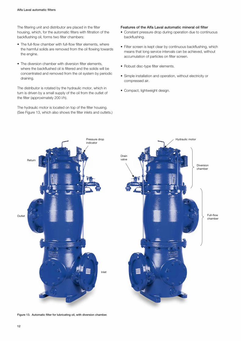
The hydraulic motor is located on top of the filter housing. (See Figure 13, which also shows the filter inlets and outlets.)
Features of the Alfa Laval automatic mineral oil filter• Constantpressuredropduringoperationduetocontinuous
backflushing.
• Filterscreeniskeptclearbycontinuousbackflushing,whichmeans that long service intervals can be achieved, without accumulation of particles on filter screen.
• Robustdisc-typefilterelements.
• Simpleinstallationandoperation,withoutelectricityorcompressed air.
• Compact,lightweightdesign.
Alfa Laval automatic filters
12
Figure 13. Automatic filter for lubricating oil, with diversion chamber.
Drain valveReturn
Pressure drop indicator
Outlet
Inlet
Hydraulic motor
Diversion chamber
Full-flow chamber

Operating principle, automatic filter with diversion chamberThe operating principle of an automatic filter is explained below . (The capital letters in the text refer to Figure 14.)
Phase 1Filtering in the full-flow chamber1. Unfiltered oil enters the full-flow chamber of the filter at
“A” and flows into chamber “B” – the space between the distributor “C” and the inner perimeter of the sleeve where the filter elements “D” are fitted.
2. From chamber “B” the oil is distributed into and through the filtering columns formed by elements “D”. The solids present are trapped.
3. The filtered oil is fed into chamber “E”, where it flows to the engine through the filter outlet “F”. Approximately 200 l/h of the filtered oil flows from chamber “E” to the hydraulic motor “H” through the feed pipe “G” to drive the hydraulic motor.
Backflushing in the full-flow chamber4. While the “full-flow” filtration takes place in all columns
except one, solids are removed in one column by back-flushing, using part of the filtered oil from chamber “E”.
5. The backflushing oil with its solids passes through channel “K” in the distributor “C” to the diversion chamber “L”.
Filtering in the diversion chamber6. The backflushing oil passes from diversion chamber “L”
through the diversion filter elements “M” to the passage in the distributor “N”.
7. Filtered oil is taken back through passage “N” in the distributor via outlet “P”.
8. In this first phase, no backflushing is performed in the diversion chamber.
Phase 2Filtering in the full-flow chamber and diversion chamberBackflushing in the diversion chamberIn this phase, the distributor has rotated one step compared with Phase 1.
9. Part of the filtered oil in chamber “E” can now pass through the channel “R” in the distributor and through the diversion filter elements “M” (from inside to outside) removing the trapped particles from the outer side of the elements.
10. The particles trapped by the filtering elements “M” can thus settle to the bottom of the diversion chamber “L”.
Removal of the filtered solids11. The solids filtered out in the diversion chamber are then
discharged from the system by periodic draining by an automatic or manual valve “V”.
13
Alfa Laval automatic filters
Figure 14. The flow of oil through an Alfa Laval filter.
N
P
L
K
E F
C
B
A
H
M
G
D
Phase 1
Phase 2
M
L
V
N
P
R
E F
A
Alfa Laval automatic filters
14
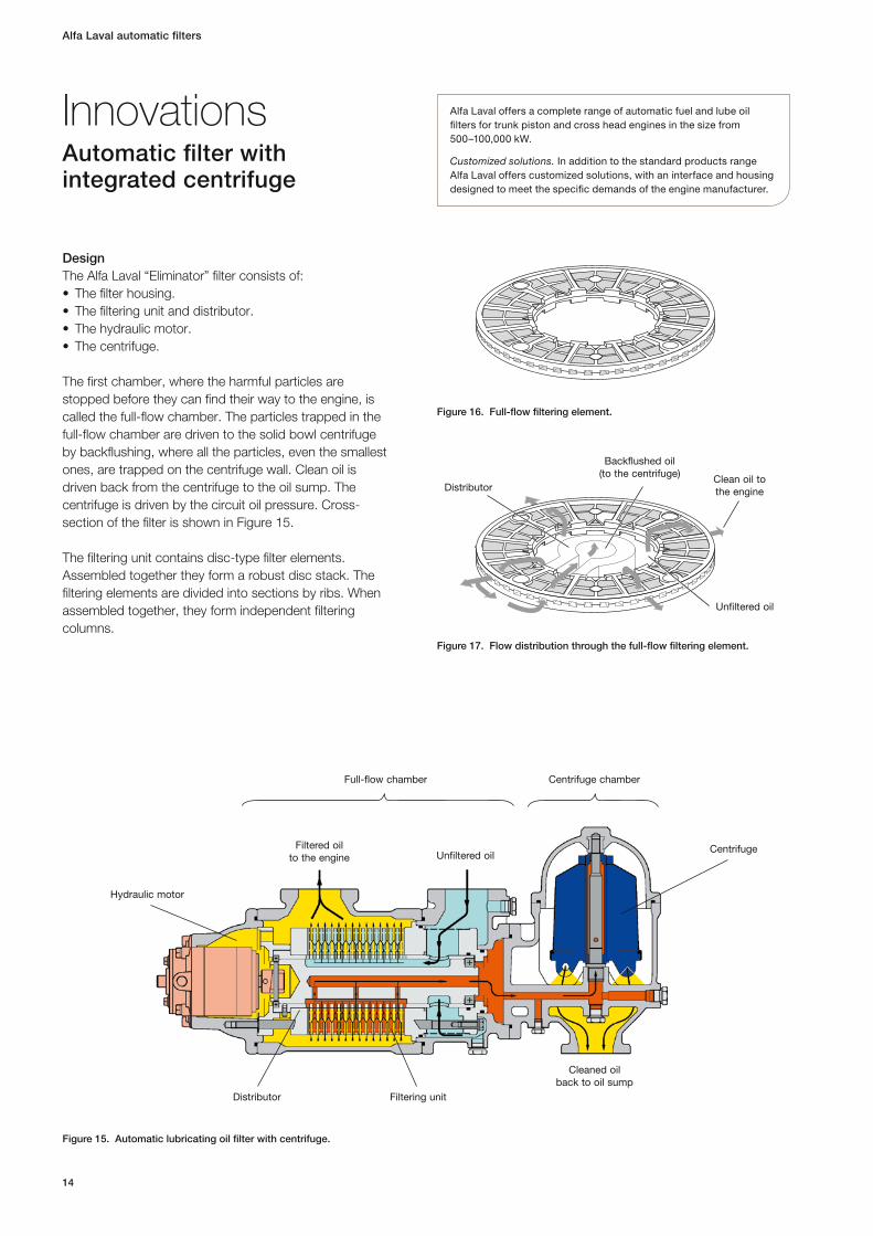
DesignThe Alfa Laval “Eliminator” filter consists of:• Thefilterhousing.• Thefilteringunitanddistributor.• Thehydraulicmotor.• Thecentrifuge.
The first chamber, where the harmful particles are stopped before they can find their way to the engine, is called the full-flow chamber. The particles trapped in the full-flow chamber are driven to the solid bowl centrifuge by backflushing, where all the particles, even the smallest ones, are trapped on the centrifuge wall. Clean oil is driven back from the centrifuge to the oil sump. The centrifuge is driven by the circuit oil pressure . Cross-section of the filter is shown in Figure 15.
The filtering unit contains disc-type filter elements. Assembled together they form a robust disc stack. The filtering elements are divided into sections by ribs. When assembled together, they form independent filtering columns.
InnovationsAutomatic filter with integrated centrifuge
Figure 15. Automatic lubricating oil filter with centrifuge.
Figure 17. Flow distribution through the full-flow filtering element.
Figure 16. Full-flow filtering element.
Distributor
Backflushed oil(to the centrifuge) Clean oil to
the engine
Unfiltered oil
Hydraulic motor
Distributor
CentrifugeFiltered oil to the engine
Full-flow chamber Centrifuge chamber
Unfiltered oil
Filtering unit
Cleaned oil back to oil sump
Alfa Laval offers a complete range of automatic fuel and lube oil filters for trunk piston and cross head engines in the size from 500–100,000 kW.
Customized solutions. In addition to the standard products range Alfa Laval offers customized solutions, with an interface and housing designed to meet the specific demands of the engine manufacturer.

15
Alfa Laval automatic filters
The filter disc stack, together with filter head, sleeve, distributor , rods and covers, forms the filtering unit. The distributor, driven by the hydraulic motor, rotates at regular intervals, feeding unfiltered oil to all columns except one, that is open for backflushing. In this way, each column is back-flushed once per full rotation of the distributor (continuous back flushing). A filtering unit is shown in Figure 18.
The distributor is rotated by the hydraulic motor, which is driven by a small amount of the clean oil downstream the filter elements. The hydraulic motor is located on the side of the filter housing (see Figure 20).
The backflushed oil from the full-flow chamber enters the centrifuge , where a high efficiency axial disc stack separates the harmful particles from the oil. The particles collect on the rotor wall. The cleaned oil is ejected through the nozzles, which give the rotating energy for the centrifuge, then the oil goes back to the lubricating oil sump by gravity. (See Figure 19.)
Features of the Alfa Laval “Eliminator” automatic mineral oil filter• Constantpressuredropduringoperationduetocontinuous
backflushing.
• Contaminationleveloftheoilkeptatverylowlevel,thanksto the high efficiency disc-stack centrifuge.
• Filterscreenkeptclearbycontinuousbackflushingwhichmeans that long service intervals can be achieved.
• Robustdisc-typefilterelements.
• Simpleinstallationandoperation,withoutelectricityandcompressed air.
• Compact,lightweightdesign.
Unfiltered oilFiltered oil to the engine
Hydraulic motor
Cleaned oil back to oil sump
Full-flow chamber Centrifuge chamber
Figure 20. “Eliminator” Automatic Filter with centrifuge.
Complete filtering
unit
Filtering element
Filter head
Distributor
Rod
Sleeve
Figure 19. Centrifuge chamber.
Backflushed oil from full-
flow filter
Rotor wall
Axial disc stack
Nozzles
To lubricating oil sump
15
Figure 18. Filtering unit.

Alfa Laval automatic filters
16
The 152 fuel oil filterThe F-152 automatic filter range provides full-flow fine filtration of heavy fuel oil (HFO) up to 700 cSt/50°C. Developed to cover all the requirements of modern two- and four-stroke engines, the F-152 requires minimal investment yet delivers highly reliable operation and true peace of mind.
The new FM152DE 60/24 contains two filtering units. Each filtering unit comprises a distribution in the centre which routes the incoming oil and controls the filtering and back flushing procedure fuel oil filters offer the smallest footprint/filtra tion capacity ratio in the market. Available with auto-manual con-figurations complete with diversion chamber it offers both a reliability and ease of operation.
Key benefits•Robust design. Reduces risk of the filter element cracking.
•Easy maintenance. Continuous backflushing significantly prevents adhesion of retained solids to filter surfaces, which results in:– No manual cleaning of filter elements.– Low and constant pressure drop across the filter
elements , which further reduces the risk of cracking.
•Self-sufficient. Use of filtered oil for the backflushing process eliminates the need for compressed air.
•Durable. Installation is recommended on the circulation side (hot loop) of the fuel oil system for maximum engine protection . The robust design and elimination of colder backflush media prevents thermal shock which can result in the formation of asphaltenes.
•Easy to troubleshoot. Constant pressure drop across the filter, combined with the pressure drop indicator, facilitates the detection of a malfunction in the fuel oil system.
•Environmental friendly. Cleaning of backflushed flow enables recirculation of fuel and reduces sludge volume to a minimum.
•Easy to install and retrofit. Easy to install in new fuel oil systems and to retrofit existing ones.
•No need for a sludge treatment unit (consumable item or manual cleaning system). The diversion chamber acts as an automatic maintenance-free sludge treatment system, collecting particles backflushed from the full-flow chamber and cleaning itself to concentrate sludge.
Fuel oil filter – F-152 range
Figure 21. Automatic fuel oil filter, FM152DE 60/24.
17
Alfa Laval automatic filters
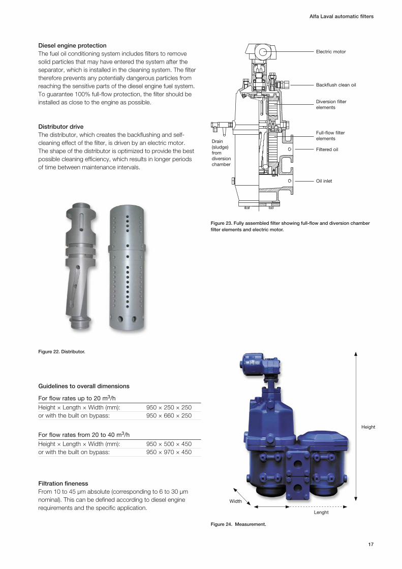
Diesel engine protectionThe fuel oil conditioning system includes filters to remove solid particles that may have entered the system after the separator, which is installed in the cleaning system. The filter therefore prevents any potentially dangerous particles from reaching the sensitive parts of the diesel engine fuel system. To guarantee 100% full-flow protection, the filter should be installed as close to the engine as possible.
Distributor driveThe distributor, which creates the backflushing and self-cleaning effect of the filter, is driven by an electric motor. The shape of the distributor is optimized to provide the best possible cleaning efficiency, which results in longer periods of time between maintenance intervals.
Guidelines to overall dimensions
For flow rates up to 20 m3/h
Height × Length × Width (mm): 950 × 250 × 250or with the built on bypass: 950 × 660 × 250
For flow rates from 20 to 40 m3/h
Height × Length × Width (mm): 950 × 500 × 450or with the built on bypass: 950 × 970 × 450
Filtration finenessFrom 10 to 45 μm absolute (corresponding to 6 to 30 μm nominal). This can be defined according to diesel engine requirements and the specific application.
Figure 22. Distributor.
Figure 23. Fully assembled filter showing full-flow and diversion chamber filter elements and electric motor.
Lenght
Width
Height
Electric motor
Backflush clean oil
Diversion filter elements
Full-flow filter elements
Drain (sludge) from diversion chamber
Filtered oil
Oil inlet
Figure 24. Measurement.

Alfa Laval automatic filters
18
The new 350-range offers a compact and lightweight lube oil filter solution for the largest trunk piston and crosshead engines.
Available in single, double and triple configurations as well as duplex auto-manual version it covers a flow range from 200–1 000 m3/h.
Innovative distribution systemWith its new innovative distribution system the 350 range offers the unique advantages with the continuous backflushing but with a reduced number of components.
Lube oil filter – 350 range
Figure 25. Automatic lube oil filter.
ApplicationThe automatic filter 350 is designed specifically for full-flow filtration of lubricating oil used in large engines that burn all types of fuels (distil-late, gas, DO, bio-fuels and HFO) dedicated to high capacities .
The 350 is intended for protection of:•Mainlubricationsystemoncrossheadand
trunk piston engines .• Servoorcontroloilsystemsincrosshead
engines .
The 350 requires minimal investment yet delivers :• Highlyreliableoperationwithminimalrunning
costs.• Truepeaceofmind.
Figure 26. Continous back flushing with a reduced number of components.
19
Alfa Laval automatic filters
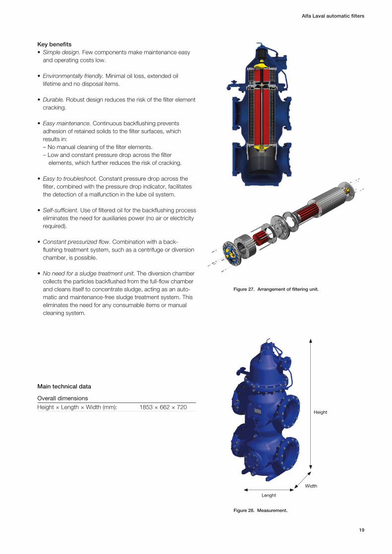
Figure 27. Arrangement of filtering unit.
Lenght
Width
Height
Key benefits•Simple design. Few components make maintenance easy
and operating costs low.
•Environmentally friendly. Minimal oil loss, extended oil lifetime and no disposal items.
•Durable. Robust design reduces the risk of the filter element cracking.
•Easy maintenance. Continuous backflushing prevents adhesion of retained solids to the filter surfaces, which results in:– No manual cleaning of the filter elements.– Low and constant pressure drop across the filter
elements , which further reduces the risk of cracking.
•Easy to troubleshoot. Constant pressure drop across the filter, combined with the pressure drop indicator, facilitates the detection of a malfunction in the lube oil system.
•Self-sufficient. Use of filtered oil for the backflushing process eliminates the need for auxiliaries power (no air or electricity required).
•Constant pressurized flow. Combination with a back-flushing treatment system, such as a centrifuge or diversion chamber , is possible.
•No need for a sludge treatment unit. The diversion chamber collects the particles backflushed from the full -flow chamber and cleans itself to concentrate sludge, acting as an auto-matic and maintenance-free sludge treatment system. This eliminates the need for any consumable items or manual cleaning system.
Main technical data
Overall dimensions
Height × Length × Width (mm): 1853 × 662 × 720
Figure 28. Measurement.
Alfa Laval automatic filters
20
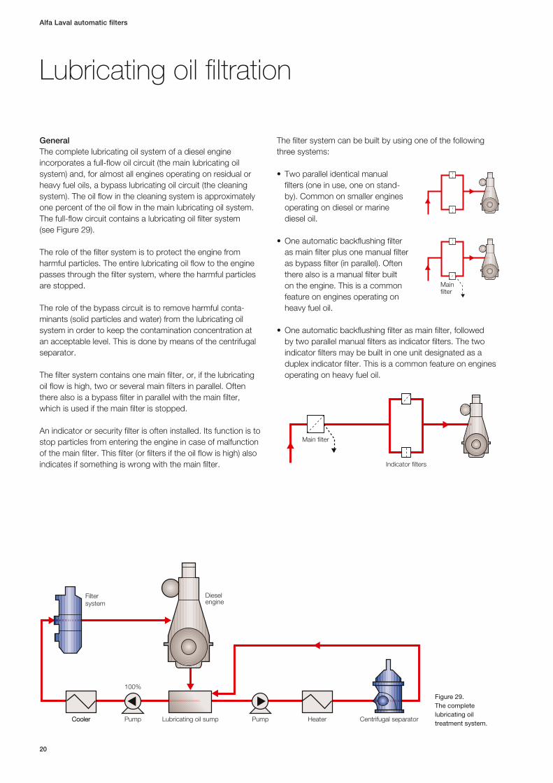
GeneralThe complete lubricating oil system of a diesel engine incorporates a full-flow oil circuit (the main lubricating oil system) and, for almost all engines operating on residual or heavy fuel oils, a bypass lubricating oil circuit (the cleaning system). The oil flow in the cleaning system is approximately one percent of the oil flow in the main lubricating oil system. The full-flow circuit contains a lubricating oil filter system (see Figure 29).
The role of the filter system is to protect the engine from harmful particles. The entire lubricating oil flow to the engine passes through the filter system, where the harmful particles are stopped.
The role of the bypass circuit is to remove harmful conta-minants (solid particles and water) from the lubricating oil system in order to keep the contamination concentration at an acceptable level. This is done by means of the centrifugal separator.
The filter system contains one main filter, or, if the lubricating oil flow is high, two or several main filters in parallel. Often there also is a bypass filter in parallel with the main filter, which is used if the main filter is stopped.
An indicator or security filter is often installed. Its function is to stop particles from entering the engine in case of malfunction of the main filter. This filter (or filters if the oil flow is high) also indicates if something is wrong with the main filter.
The filter system can be built by using one of the following three systems:
• Twoparallelidenticalmanualfilters (one in use, one on stand-by). Common on smaller engines operating on diesel or marine diesel oil.
•Oneautomaticbackflushingfilteras main filter plus one manual filter as bypass filter (in parallel). Often there also is a manual filter built on the engine. This is a common feature on engines operating on heavy fuel oil.
•Oneautomaticbackflushingfilterasmainfilter,followedby two parallel manual filters as indicator filters. The two indicator filters may be built in one unit designated as a duplex indicator filter. This is a common feature on engines operating on heavy fuel oil.
Lubricating oil filtration
Filtersystem
Lubricating oil sumpPump PumpCoolerCooler Heater
100%
Centrifugal separator
Dieselengine
Figure 29.The complete lubricating oil treatment system.
Mainfilter
Main filter
Indicator filters

21
Alfa Laval automatic filters
Denomination of Alfa Laval lubricating oil filtersThe denomination of lubricating oil filters is built up in the following manner:
Single or module filter:Protector T 280 D 50 / 8 A07 1 2 4 5 6 7 8
Duplex filter:Protector T L 280 D 50 / 8 A07 1 2 3 4 5 6 7 8
1 Generic name for the Alfa Laval filters
2 Type of main filter T Automatic filter for Trunk Piston Engines X Automatic filter for Crosshead Engines L Manual filter
3 Type of secondary filter (if duplex filters only) T Automatic filter for Trunk Piston Engines X Automatic filter for Crosshead Engines L Manual filter
4 External diameter of the filtering elements (automatic filters), of the filter insert (manual filters). Dimensions: 120, 140, 150, 240, 280, 350.
5 Type of diversion chamber – No diversion chamber D Filter with diversion chamber C Filter with centrifugal separator
6 Automatic filters: Number of full-flow filtering elements (total number of elements for module filters).
Manual filters: Filtering area in dm3 (total surface area of module filters).
7 Number of diversion elements (if applicable).
8 Filtration code.
Alfa Laval lubricating oil filters can be equipped with different finenesses of filter screens. The filter fineness is specified by the engine manufacturer. A sketch of an Alfa Laval lubricating oil filter installation is shown in Figure 30.
The filter normally has a pressure drop between the oil entering the filter and the clean oil (P1–P2) of 0.2–0.5 bar. The amount of filtered oil needed to backflush the filter screen and drive the hydraulic motor (Q3) is between three and five percent of the oil entering the filter.
For reliable backflushing and driving of the hydraulic motor, it is important to have a pressure difference of at least 1.4 bar for crosshead engines and 2.8 bar for trunk piston engines between the filtered oil and the oil returning to the sump (P2–P3).
Dieselengine
Filter
2
3
Cooler
Lubricatingoil sump
Pump
Stand-bypump
1
Figure 30. Installation flow sheet for Alfa Laval lubricating oil filter.
Alfa Laval automatic filters
22
Alfa Laval lubricating oil filters for crosshead enginesThe Alfa Laval lubricating oil filters for crosshead engines differ from those for trunk piston engines. Higher flow rate of the lubricating oil, different demands on filter fineness, properties of contaminants, low oil pressure at the inlet to the engine, etc., are factors that require additional lubricating oil filter specifications on the part of the engine manufacturer.
Pre-lubricationIn some installations the filter must operate during pre -lubrication. (The engine is stopped, but the lubricating oil is pumped with reduced capacity through the engine for rapid startup.)
This can influence the filtering process. If the pre-lubrication period is longer than 24 hours and the pressure difference between the cleaned oil and the return oil to sump (P2–P3) is less than 0.8 bar, the pressure difference is not sufficient to operate the automatic filter.
In this case an additional filter has to be installed in a separate prelubrication circuit.
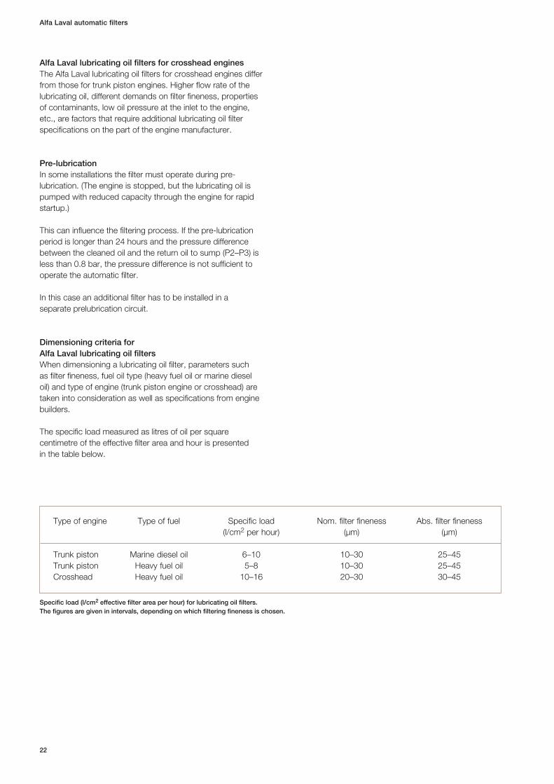
Dimensioning criteria for Alfa Laval lubricating oil filtersWhen dimensioning a lubricating oil filter, parameters such as filter fineness, fuel oil type (heavy fuel oil or marine diesel oil) and type of engine (trunk piston engine or crosshead) are taken into consideration as well as specifications from engine builders.
The specific load measured as litres of oil per square centimetre of the effective filter area and hour is presented in the table below.
Type of engine Type of fuel Specific load Nom. filter fineness Abs. filter fineness (l/cm2 per hour) (µm) (µm)
Trunk piston Marine diesel oil 6–10 10–30 25–45 Trunk piston Heavy fuel oil 5–8 10–30 25–45 Crosshead Heavy fuel oil 10–16 20–30 30–45
Specific load (l/cm2 effective filter area per hour) for lubricating oil filters. The figures are given in intervals, depending on which filtering fineness is chosen.
23
Alfa Laval automatic filters
Alfa Laval automatic filters
24
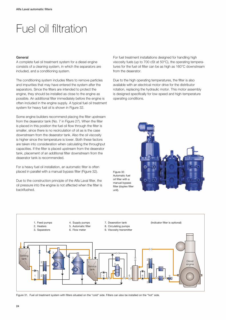
GeneralA complete fuel oil treatment system for a diesel engine consists of a cleaning system, in which the separators are included, and a conditioning system.
The conditioning system includes filters to remove particles and impurities that may have entered the system after the separators. Since the filters are intended to protect the engine, they should be installed as close to the engine as possible . An additional filter immediately before the engine is often included in the engine supply. A typical fuel oil treatment system for heavy fuel oil is shown in Figure 32.
Some engine builders recommend placing the filter upstream from the deaerator tank (No. 7 in Figure 27). When the filter is placed in this position the fuel oil flow through the filter is smaller, since there is no recirculation of oil as is the case downstream from the deaerator tank. Also the oil viscosity is higher since the temperature is lower. Both these factors are taken into consideration when calculating the throughput capacities. If the filter is placed upstream from the deaerator tank, placement of an additional filter downstream from the deaerator tank is recommended.
For a heavy fuel oil installation, an automatic filter is often placed in parallel with a manual bypass filter (Figure 32).
Due to the construction principle of the Alfa Laval filter, the oil pressure into the engine is not affected when the filter is backflushed.
For fuel treatment installations designed for handling high viscosity fuels (up to 700 cSt at 50°C), the operating tempera-tures for the fuel oil filter can be as high as 160°C downstream from the deaerator.
Due to the high operating temperatures, the filter is also available with an electrical motor drive for the distributor rotation, replacing the hydraulic motor. This motor assembly is designed specifically for low-speed and high-temperature operating conditions.
Fuel oil filtration
6
7
8 91
2
2
3
3Settling
tank
Servicetank
5
4FM
2
2Dieselengine
1. Feed pumps 2. Heaters 3. Separators
4. Supply pumps 5. Automatic filter 6. Flow meter
7. Deaeration tank 8. Circulating pumps 9. Viscosity transmitter
(Indicator filter is optional)
Figure 31. Fuel oil treatment system with filters situated on the “cold” side. Filters can also be installed on the “hot” side.
Figure 32. Automatic fuel oil filter with a manual bypass filter (duplex filter unit).
25
Alfa Laval automatic filtersAlfa Laval automatic filters
This arrangement provides simplified maintenance and assures rotation of the distributor even in the most arduous operating conditions.
The motor can be supplied for 110 or 220 VAC supply, 50 or 60 Hz, and it draws around 0.1A to 0.4A according to filter size and current during normal operation.
The electrical motor can be upgraded onto existing installa-tions using a simple upgrade kit available for most models.
Designation and operating conditions for fuel oil filtersThe denomination of fuel oil filters is built up in the following manner:
Single or module filterProtector F 150 D E 30 / 12 A05 1 2 4 5 6 7 8 9
Duplex filterProtector F M 150 D E 30 / 12 A05 1 2 3 4 5 6 7 8 9
1 Generic name for the Alfa Laval filters
2 Type of main filter F Automatic fuel oil filter M Manual fuel oil filter
3 Type of secondary filter (if duplex filters only) F Automatic fuel oil filter M Manual fuel oil filter
4 External diameter of the filtering elements (automatic filters), of the filter insert (manual filters). Dimensions: 120, 140, 150, 240, 280.
5 Type of diversion chamber D filter with diversion chamber
6 Type of driving motor for backflushing – Hydraulic motor E Electric motor
7 Automatic filters: Number of full-flow filtering elements (total number of elements for module filters)
Manual filters: Filtering area, in dm3 (total surface area of module filters)
8 Number of diversion elements (if applicable)
9 Filtration code
The use of the electrical motor means that this filter is suitable for “hot” and “cold” side installations, according to customer requirements and without limitations.
To ensure proper backflushing (and rotation of the hydraulic motor on the automatic filter when fitted), it is important that the pressure difference between the filtered oil and the oil going back to the suction side of the fuel oil pump (P2–P3) is at least 2 bar. For this reason the viscosity of the fuel oil should also be below 75 cSt when the filter is placed down-stream from the deaerator tank (150 cSt upstream from the deaerator tank). In contrast to the lubricating oil filter, the hydraulic motor of the fuel oil filter is driven by the filtered oil from the diversion chamber.
The pressure drop between the unfiltered and filtered oil (P1–P2) is normally 0.2–0.5 bar. The necessary amount of oil for backflushing the filter is normally 7–15 percent of the oil flow entering the filter. The same oil that is used for back-flushing is also used to drive the hydraulic motor.
Another factor that influences the sizing of the filter is the fineness of the filter screen. This is determined by the require-ments of the diesel engine manufacturers. The filter size for a given fuel flow increases when a smaller filter screen is used, due to the fact that the number of particles collected on the filter screen will increase.
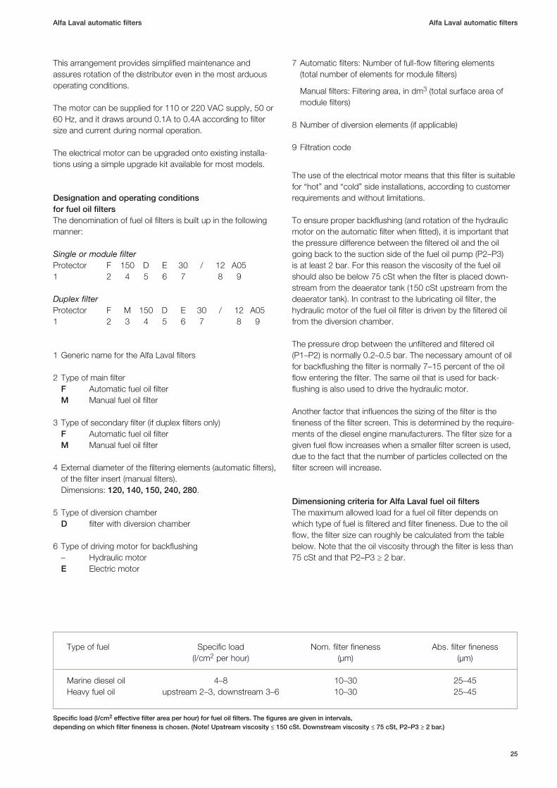
Dimensioning criteria for Alfa Laval fuel oil filtersThe maximum allowed load for a fuel oil filter depends on which type of fuel is filtered and filter fineness. Due to the oil flow, the filter size can roughly be calculated from the table below. Note that the oil viscosity through the filter is less than 75 cSt and that P2–P3 ≥ 2 bar.
Type of fuel Specific load Nom. filter fineness Abs. filter fineness (l/cm2 per hour) (µm) (µm)
Marine diesel oil 4–8 10–30 25–45 Heavy fuel oil upstream 2–3, downstream 3–6 10–30 25–45
Specific load (l/cm2 effective filter area per hour) for fuel oil filters. The figures are given in intervals, depending on which filter fineness is chosen. (Note! Upstream viscosity ≤ 150 cSt. Downstream viscosity ≤ 75 cSt, P2–P3 ≥ 2 bar.)
Alfa Laval automatic filters
26
Alfa Laval supplies each delivered automatic filter with full documentation either as paper copies or as PDF (Portable Document Format) files on a CD.
The instruction manual covers: • Safety• Systemdescription•Operatinginstructions• Troubleshooting•Maintenancemanual• Sparepartscatalogue
Documentation
Commissioning, service, support and training in all aspects of oil treatment are globally available through Alfa Laval’s net-work. Alfa Laval also provides spare and replacement parts for all service needs. All services can be incorporated into tailored “Performance Agreements”.
The full support includes:
•AglobalnetworkofServiceCentres•DistributionCentreswith24/7emergencyphoneservice•Onboardinspectionsservice•Training•Preventivemaintenanceprogram•Consultancyandoptimization•E-business
The Alfa Laval automatic filters are ideal not only for newbuildings, but also for replacing old or inefficient filters on existing installations.
A compact design with small footprint and no required external power supply, compressed air or electricity, allows for a flexible installation.
No disposables and long service intervals can drastically reduce operation and maintenance costs.
Retrofitting
Alfa Laval ensures that the whole standard range of automatic filters fulfil the requirements of all major clas-sification societies. Upon request, Alfa Laval delivers the automatic filters with individual test certificates. This includes approval by the respective society, as well as, the factory test certificate.
Classification society approval
Service and support

27
Alfa Laval automatic filters
EMD00100EN 1210
Alfa
Lav
al is
a t
rad
emar
k re
gis
tere
d a
nd o
wne
d b
y A
lfa L
aval
Co
rpo
rate
AB
.A
lfa L
aval
res
erve
s th
e ri
ght
to
cha
nge
spec
ifica
tions
with
out
pri
or
notifi
catio
n.
ww
w.f
oto
skri
ft.s
e
Alfa Laval in brief
Alfa Laval is a leading global provider of specialized products and engineered solutions.
Our equipment, systems and services are dedicated to helping customers to optimize the perform ance of their pro-cesses. Time and time again.
We help our customers to heat, cool, separate and transport products such as oil, water, chemicals, beverages, foodstuff, starch and pharmaceuticals.
Our worldwide organization works closely with customers in almost 100 countries to help them stay ahead.
How to contact Alfa Laval
Up-to-date Alfa Laval contact details for all countries are always available on our website at www.alfalaval.com