Embed Size (px)
Citation preview
HAL Id: hal-01351735https://hal.archives-ouvertes.fr/hal-01351735
Submitted on 4 Aug 2016
HAL is a multi-disciplinary open accessarchive for the deposit and dissemination of sci-entific research documents, whether they are pub-lished or not. The documents may come fromteaching and research institutions in France orabroad, or from public or private research centers.
L’archive ouverte pluridisciplinaire HAL, estdestinée au dépôt et à la diffusion de documentsscientifiques de niveau recherche, publiés ou non,émanant des établissements d’enseignement et derecherche français ou étrangers, des laboratoirespublics ou privés.
Automated visual inspection of an airplane exteriorIgor Jovančević, Jean-José Orteu, Thierry Sentenac, Rémi Gilblas
To cite this version:Igor Jovančević, Jean-José Orteu, Thierry Sentenac, Rémi Gilblas. Automated visual inspection of anairplane exterior. 12th International Conference on Quality Control by Artificial Vision (QCAV’2015),Jun 2015, Le Creusot, France. �10.1117/12.2182811�. �hal-01351735�
Automated visual inspection of an airplane exterior
Igor Jovancevic, Jean-Jose Orteu, Thierry Sentenac and Remi Gilblas
Universite de Toulouse ; INSA, UPS, Mines Albi, ISAE ; ICA (Institut Clement Ader) ;Campus Jarlard, F-81013 Albi, France
ABSTRACT
This paper deals with the inspection of an airplane using a Pan-Tilt-Zoom camera mounted on a mobile robotmoving around the airplane. We present image processing methods for detection and inspection of four differenttypes of items on the airplane exterior. Our detection approach is focused on the regular shapes such as roundedcorner rectangles and ellipses, while inspection relies on clues such as uniformity of isolated image regions,convexity of segmented shapes and periodicity of the image intensity signal. The initial results are promisingand demonstrate the feasibility of the envisioned robotic system.
Keywords: inspection, airplane exterior, image processing, PTZ camera
1. INTRODUCTION
Airplanes are periodically inspected, either on the airport tarmac between two fligths or in a hangar duringmaintenance operations. Today, these inspections are done by human operators, mainly visually and sometimeswith the help of some inspection tools, for instance to evaluate the criticality of a crack detected on the planefuselage. In order to make the inspection quicker, more exhaustive and more accurate, as well as for traceabilityreasons, a multi-partners research project is being carried on in order to develop a mobile robot equipped withseveral optical sensors (cameras and 3D scanners) to perform an automatic inspection of an airplane.
The approach chosen in the project is based on an autonomous mobile robot on the ground, capable tocommunicate with human operators and infrastructures around the aircraft. The collaborative robot (cobot) hasto move autonomously between different checkpoints while interacting with pilot, workers, vehicles and airportinformation systems. In addition to the long range navigation task, at each checkpoint (around twenty for a pre-flight inspection) the cobot has to perform an inspection task of several items (probes, doors, etc.). Around 240items to be inspected are identified for the whole plane. Automated image acquisition is provided by controllingsensors and pointing them towards the item to be inspected. This is feasible by taking into account the positionof the robot with respect to the plane and the position of the item in the 3D model of the plane. Inspection isthen performed by processing the Pan-Tilt-Zoom (PTZ) camera images and 3D point clouds provided by a 3Dscanner. For each item, integrity or right configuration should be verified. Accordingly, one of the three generalstrategies is then chosen and applied: (A) single view 2D image processing; (B) model based image processing(single view image processing by using 3D CAD model of the element); (C) processing of 3D point clouds. Firststrategy is preferred whenever possible, for the time reasons. Second strategy is used when image processing isnot sufficient, for ex. for inspecting probes. Third strategy is employed for detecting damages on the airplaneskin (cracks, dents, bumps).
Robotic airplane inspection from the ground, based on computer vision, is a specific application not yetstudied. Previous efforts1–5 were mainly focused on detailed airplane skin inspection with robot crawling onthe airplane surface. In most cases, industrial automation systems6 are used to inspect known objects at fixedpositions with appropriate illumination necessary to extract meaningful features. In our application, however,sensors are mounted on the moving robot and no additional illumination is used. Moreover, our intention is toenable robot to cover as many items as possible from one position, i.e. to move as less as possible. Since 2Dimage processing approaches are preferred, initial strategy is to assess performances of the 2D image processingmethods and this article is focused on presenting these results.
E-mail: [email protected]
Twelfth International Conference on Quality Control by Artificial Vision, edited by Fabrice Meriaudeau, Olivier Aubreton, Proc. of SPIE Vol. 9534, 95340Y · © 2015
SPIE · CCC code: 0277-786X/15/$18 · doi: 10.1117/12.2182811
Proc. of SPIE Vol. 9534 95340Y-1
2. PROPOSED METHODS FOR FOUR TYPES OF ITEMS
Results in inspecting some of the items will be presented. For all the items, the approach comprises detection ofregion of interest (ROI) and the inspection, i.e. making decision. When possible, the presence of other detectableelements is exploited to narrow down the search area for an item to be inspected. Adopted strategy is to detectthe ROI, point the camera in order to have the item in the center of the image, zoom in and finally perform theinspection on the zoomed item. Since the inspection is done only on zoomed images, we can accept certain levelof imprecision in ROI detection on small zoom images.
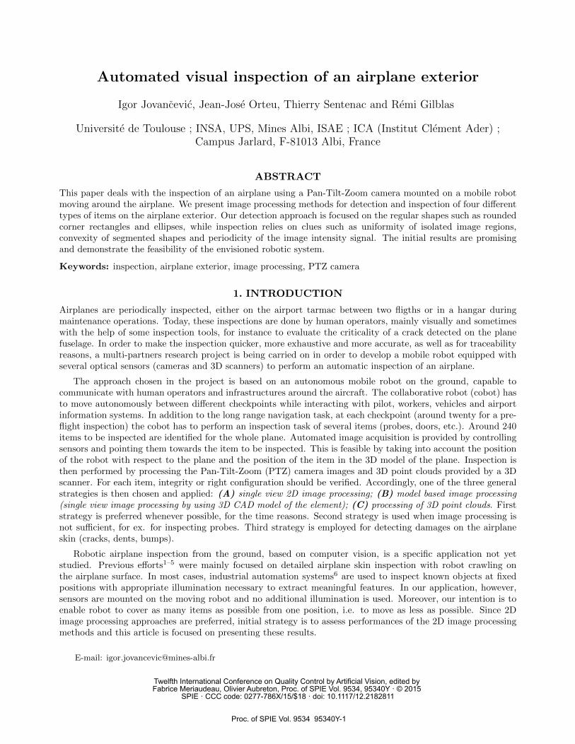
Usual weakness of an inspection system is being specialized in inspecting one particular object. In that sense,each of the items on the plane could be an isolated, specific, inspection problem. Our intention is to design moregeneral strategies, applicable to a class of similar items by changing just parameters and geometry. Methods aretested on a dataset of real A320 airplane images acquired by PTZ camera in AIRBUS hangar (Fig. 1).
Figure 1. Robot in the hangar (Courtesy of AIRBUS).
2.1 Preprocessing step: background removal
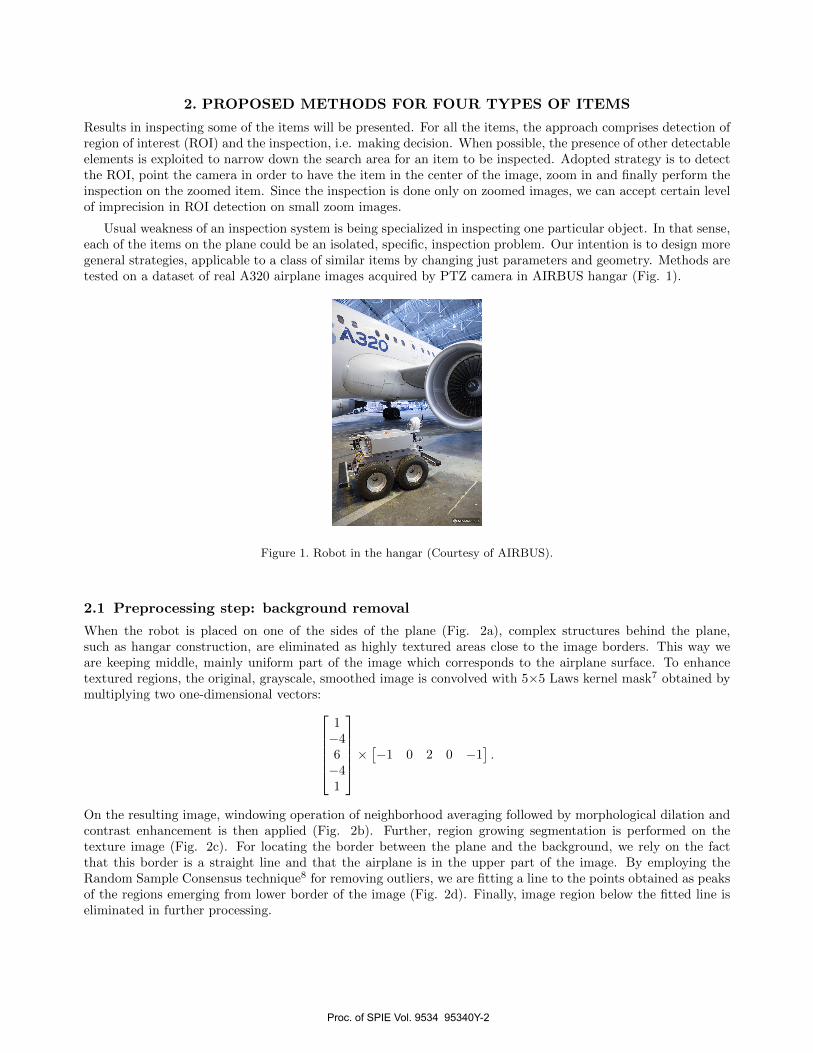
When the robot is placed on one of the sides of the plane (Fig. 2a), complex structures behind the plane,such as hangar construction, are eliminated as highly textured areas close to the image borders. This way weare keeping middle, mainly uniform part of the image which corresponds to the airplane surface. To enhancetextured regions, the original, grayscale, smoothed image is convolved with 5×5 Laws kernel mask7 obtained bymultiplying two one-dimensional vectors:
1−46−41
×[−1 0 2 0 −1
].
On the resulting image, windowing operation of neighborhood averaging followed by morphological dilation andcontrast enhancement is then applied (Fig. 2b). Further, region growing segmentation is performed on thetexture image (Fig. 2c). For locating the border between the plane and the background, we rely on the factthat this border is a straight line and that the airplane is in the upper part of the image. By employing theRandom Sample Consensus technique8 for removing outliers, we are fitting a line to the points obtained as peaksof the regions emerging from lower border of the image (Fig. 2d). Finally, image region below the fitted line iseliminated in further processing.
Proc. of SPIE Vol. 9534 95340Y-2
':
:
o`
(a) Original image. (b) Texture image after dilation andcontrast enhancement.
(c) Region growing segmentation ontexture image.
(d) Line fitted on the points which areon the top of the regions emerging fromthe low border of the image.
Figure 2. Removing the background.
2.2 Oxygen bay handle
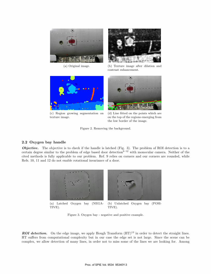
Objective. The objective is to check if the handle is latched (Fig. 3). The problem of ROI detection is to acertain degree similar to the problem of edge based door detection9–12 with monocular camera. Neither of thecited methods is fully applicable to our problem. Ref. 9 relies on corners and our corners are rounded, whileRefs. 10, 11 and 12 do not enable rotational invariance of a door.
(a) Latched Oxygen bay (NEGA-TIVE).
(b) Unlatched Oxygen bay (POSI-TIVE).
Figure 3. Oxygen bay - negative and positive example.
ROI detection. On the edge image, we apply Hough Transform (HT)13 in order to detect the straight lines.HT suffers from computational complexity but in our case the edge set is not large. Since the scene can becomplex, we allow detection of many lines, in order not to miss some of the lines we are looking for. Among
Proc. of SPIE Vol. 9534 95340Y-3
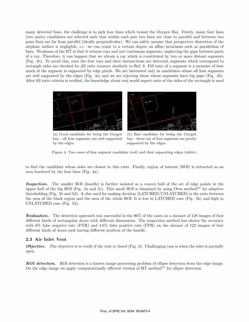
many detected lines, the challenge is to pick four lines which bound the Oxygen Bay. Firstly, many four lines(two pairs) candidates are selected such that within each pair two lines are close to parallel and between twopairs lines are far from parallel (ideally perpendicular). We can safely assume that perspective distortion of theairplane surface is negligible, i.e. we can count to a certain degree on affine invariants such as parallelism oflines. Weakness of the HT is that it returns rays and not continuous segments, neglecting the gaps between partsof a ray. Therefore, it can happen that we obtain a ray which is constituted by two or more distant segments(Fig. 4b). To avoid this, once the four rays and their intersections are detected, segments which correspond torectangle sides are checked for fill ratio measure similarly to Ref. 9. Fill ratio of a segment is a measure of howmuch of the segment is supported by edge pixels. We are interested only in candidates whose all four segmentsare well supported by the edges (Fig. 4a) and we are rejecting those whose segments have big gaps (Fig. 4b).After fill ratio criteria is verified, the knowledge about real world aspect ratio of the sides of the rectangle is used
(a) Good candidate for being the Oxygenbay - all four segments are well supportedby the edges.
(b) Bad candidate for being the Oxygenbay - three out of four segments are poorlysupported by the edges.
Figure 4. Two cases of four segment candidate (red) and their supporting edges (white).
to find the candidate whose sides are closest to this ratio. Finally, region of interest (ROI) is extracted as anarea bordered by the four lines (Fig. 4a).
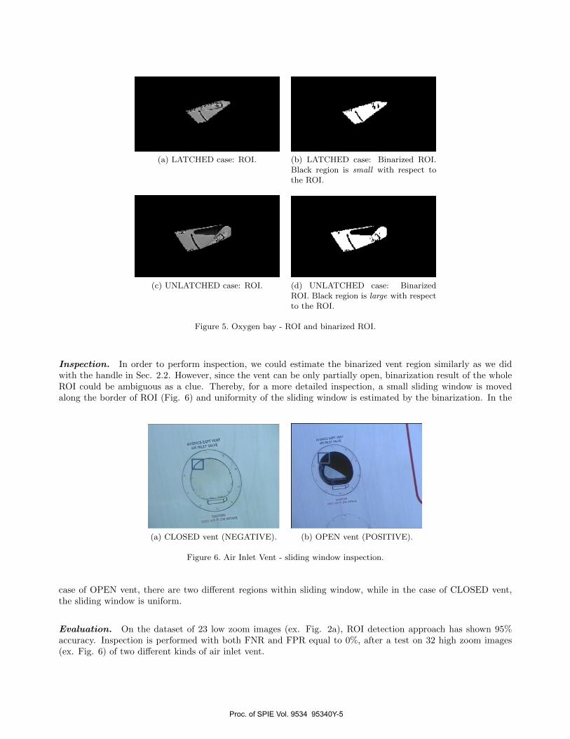
Inspection. The smaller ROI (handle) is further isolated as a convex hull of the set of edge points in theupper half of the big ROI (Fig. 5a and 5c). This small ROI is binarized by using Otsu method14 for adaptivethresholding (Fig. 5b and 5d). A clue used for making decision (LATCHED/UNLATCHED) is the ratio betweenthe area of the black region and the area of the whole ROI. It is low in LATCHED case (Fig. 5b) and high inUNLATCHED case (Fig. 5d).
Evaluation. The detection approach was successful in the 96% of the cases on a dataset of 128 images of fourdifferent kinds of rectangular doors with different dimensions. The inspection method has shown the accuracywith 0% false negative rate (FNR) and 4.6% false positive rate (FPR) on the dataset of 122 images of fourdifferent kinds of doors each having different position of the handle.
2.3 Air Inlet Vent
Objective. The objective is to verify if the vent is closed (Fig. 6). Challenging case is when the inlet is partiallyopen.
ROI detection. ROI detection is a known image processing problem of ellipse detection from the edge image.On the edge image we apply computationally efficient version of HT method15 for ellipse detection.
Proc. of SPIE Vol. 9534 95340Y-4
A.10Nic5 EOVT VENT
V R iNEET WIVE
EAMONN... ASR ROW INTAKE
1
(a) LATCHED case: ROI. (b) LATCHED case: Binarized ROI.Black region is small with respect tothe ROI.
(c) UNLATCHED case: ROI. (d) UNLATCHED case: BinarizedROI. Black region is large with respectto the ROI.
Figure 5. Oxygen bay - ROI and binarized ROI.
Inspection. In order to perform inspection, we could estimate the binarized vent region similarly as we didwith the handle in Sec. 2.2. However, since the vent can be only partially open, binarization result of the wholeROI could be ambiguous as a clue. Thereby, for a more detailed inspection, a small sliding window is movedalong the border of ROI (Fig. 6) and uniformity of the sliding window is estimated by the binarization. In the
(a) CLOSED vent (NEGATIVE). (b) OPEN vent (POSITIVE).
Figure 6. Air Inlet Vent - sliding window inspection.
case of OPEN vent, there are two different regions within sliding window, while in the case of CLOSED vent,the sliding window is uniform.
Evaluation. On the dataset of 23 low zoom images (ex. Fig. 2a), ROI detection approach has shown 95%accuracy. Inspection is performed with both FNR and FPR equal to 0%, after a test on 32 high zoom images(ex. Fig. 6) of two different kinds of air inlet vent.
Proc. of SPIE Vol. 9534 95340Y-5
.-1 s1}!l r`' qq aTT' fiS-``yy71R1ik
2.4 Static ports
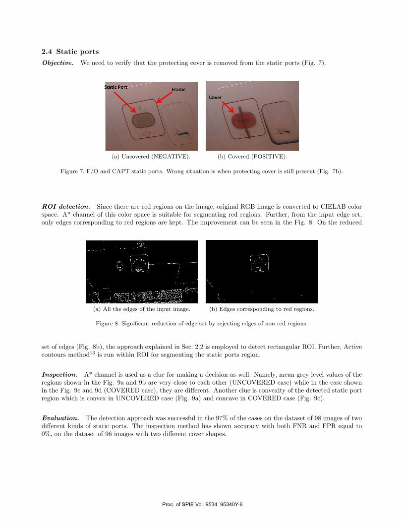
Objective. We need to verify that the protecting cover is removed from the static ports (Fig. 7).
(a) Uncovered (NEGATIVE). (b) Covered (POSITIVE).
Figure 7. F/O and CAPT static ports. Wrong situation is when protecting cover is still present (Fig. 7b).
ROI detection. Since there are red regions on the image, original RGB image is converted to CIELAB colorspace. A* channel of this color space is suitable for segmenting red regions. Further, from the input edge set,only edges corresponding to red regions are kept. The improvement can be seen in the Fig. 8. On the reduced
(a) All the edges of the input image. (b) Edges corresponding to red regions.
Figure 8. Significant reduction of edge set by rejecting edges of non-red regions.
set of edges (Fig. 8b), the approach explained in Sec. 2.2 is employed to detect rectangular ROI. Further, Activecontours method16 is run within ROI for segmenting the static ports region.
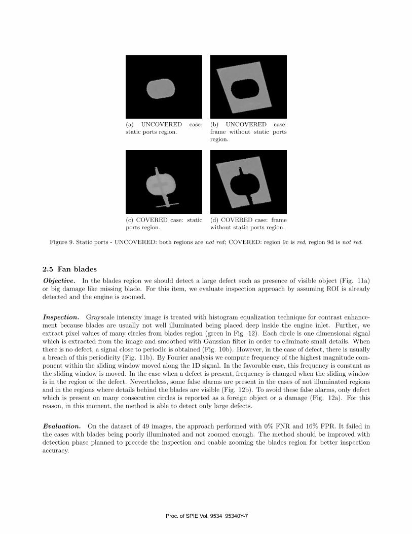
Inspection. A* channel is used as a clue for making a decision as well. Namely, mean grey level values of theregions shown in the Fig. 9a and 9b are very close to each other (UNCOVERED case) while in the case shownin the Fig. 9c and 9d (COVERED case), they are different. Another clue is convexity of the detected static portregion which is convex in UNCOVERED case (Fig. 9a) and concave in COVERED case (Fig. 9c).
Evaluation. The detection approach was successful in the 97% of the cases on the dataset of 98 images of twodifferent kinds of static ports. The inspection method has shown accuracy with both FNR and FPR equal to0%, on the dataset of 96 images with two different cover shapes.
Proc. of SPIE Vol. 9534 95340Y-6
44 tl
(a) UNCOVERED case:static ports region.
(b) UNCOVERED case:frame without static portsregion.
(c) COVERED case: staticports region.
(d) COVERED case: framewithout static ports region.
Figure 9. Static ports - UNCOVERED: both regions are not red ; COVERED: region 9c is red, region 9d is not red.
2.5 Fan blades
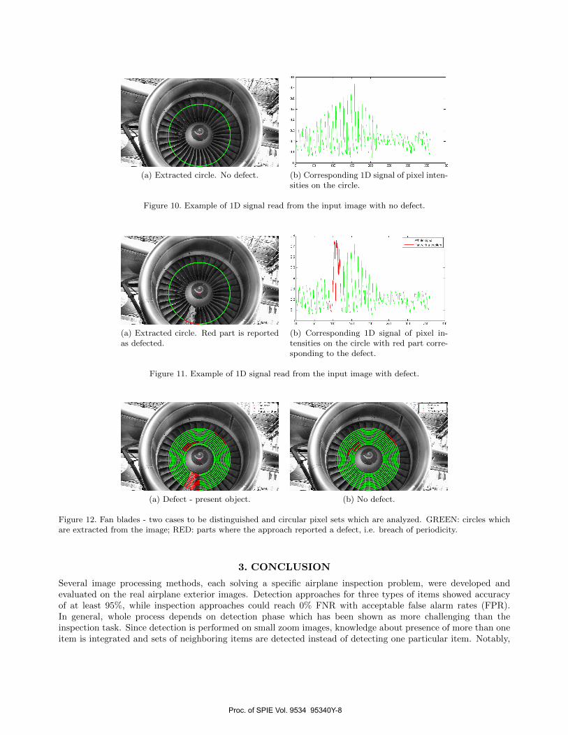
Objective. In the blades region we should detect a large defect such as presence of visible object (Fig. 11a)or big damage like missing blade. For this item, we evaluate inspection approach by assuming ROI is alreadydetected and the engine is zoomed.
Inspection. Grayscale intensity image is treated with histogram equalization technique for contrast enhance-ment because blades are usually not well illuminated being placed deep inside the engine inlet. Further, weextract pixel values of many circles from blades region (green in Fig. 12). Each circle is one dimensional signalwhich is extracted from the image and smoothed with Gaussian filter in order to eliminate small details. Whenthere is no defect, a signal close to periodic is obtained (Fig. 10b). However, in the case of defect, there is usuallya breach of this periodicity (Fig. 11b). By Fourier analysis we compute frequency of the highest magnitude com-ponent within the sliding window moved along the 1D signal. In the favorable case, this frequency is constant asthe sliding window is moved. In the case when a defect is present, frequency is changed when the sliding windowis in the region of the defect. Nevertheless, some false alarms are present in the cases of not illuminated regionsand in the regions where details behind the blades are visible (Fig. 12b). To avoid these false alarms, only defectwhich is present on many consecutive circles is reported as a foreign object or a damage (Fig. 12a). For thisreason, in this moment, the method is able to detect only large defects.
Evaluation. On the dataset of 49 images, the approach performed with 0% FNR and 16% FPR. It failed inthe cases with blades being poorly illuminated and not zoomed enough. The method should be improved withdetection phase planned to precede the inspection and enable zooming the blades region for better inspectionaccuracy.
Proc. of SPIE Vol. 9534 95340Y-7
r
OS
wmm. signalParr xilb. problem
V1
551 100 2160 260 SOO 360 400
+
(a) Extracted circle. No defect. (b) Corresponding 1D signal of pixel inten-sities on the circle.
Figure 10. Example of 1D signal read from the input image with no defect.
(a) Extracted circle. Red part is reportedas defected.
(b) Corresponding 1D signal of pixel in-tensities on the circle with red part corre-sponding to the defect.
Figure 11. Example of 1D signal read from the input image with defect.
(a) Defect - present object. (b) No defect.
Figure 12. Fan blades - two cases to be distinguished and circular pixel sets which are analyzed. GREEN: circles whichare extracted from the image; RED: parts where the approach reported a defect, i.e. breach of periodicity.
3. CONCLUSION
Several image processing methods, each solving a specific airplane inspection problem, were developed andevaluated on the real airplane exterior images. Detection approaches for three types of items showed accuracyof at least 95%, while inspection approaches could reach 0% FNR with acceptable false alarm rates (FPR).In general, whole process depends on detection phase which has been shown as more challenging than theinspection task. Since detection is performed on small zoom images, knowledge about presence of more than oneitem is integrated and sets of neighboring items are detected instead of detecting one particular item. Notably,
Proc. of SPIE Vol. 9534 95340Y-8
our method for red regions detection has been shown quite robust, therefore it is often employed to facilitatedetection of other items. In the article, we presented inspection approaches for four representative types of items.Nevertheless, other items marked as highly important by human inspectors, has been treated as well.
ACKNOWLEDGMENTS
This work is part of the AIR-COBOT project (http://aircobot.akka.eu) approved by the Aerospace Valleyworld competitiveness cluster. We gratefully acknowledge financial support from the French Government viathe Single Inter-Ministry Fund (FUI). The partners of the AIR-COBOT project (AKKA TECHNOLOGIES,AIRBUS Group, ARMINES, 2MoRO Solutions, LAAS-CNRS, M3 SYSTEMS and STERELA) are also gratefullyacknowledged for their support.
REFERENCES
[1] Siegel, M., Gunatilake, P., and Podnar, G., “Robotic assistants for aircraft inspectors,” InstrumentationMeasurement Magazine, IEEE 1, 16–30 (Mar 1998).
[2] Siegel, M., Kaufman, W., and Alberts, C., “Mobile robots for difficult measurements in difficult environ-ments: Application to aging aircraft inspection,” Robotics and Autonomous Systems 11(3-4), 187 – 194(1993).
[3] Davis, I. L. and Siegel, M., “Automated nondestructive inspector of aging aircraft,” in [Measurement Tech-nology and Intelligent Instruments ], Zhu, L., ed., Proc. SPIE 2101, 190–201, SPIE, Wuhan, China (1993).
[4] Gunatilake, P. and Siegel, M., “Remote enhanced visual inspection of aircraft by a mobile robot,” in [Proc.1998 IEEE Int’l Workshop on Emerging Technologies, Intelligent Measurement and Virtual Systems forInstrumentation and Measurement (ETIMVIS’98) ], IEEE, Saint-Paul (MN, USA) (15-16 May 1998).
[5] Mumtaz, R., Mumtaz, M., Mansoor, A. B., and Masood, H., “Computer aided visual inspection of aircraftsurfaces,” International Journal of Image Processing (IJIP) 6(1), 38–53 (2012).
[6] Malamas, E. N., Petrakis, E. G., Zervakis, M., Petit, L., and Legat, J.-D., “A survey on industrial visionsystems, applications and tools,” Image and Vision Computing 21(2), 171 – 188 (2003).
[7] Laws, K., “Texture energy measures,” in [Proceedings of image understanding workshop ], 47–51 (November1979).
[8] Fischler, M. and Bolles, R., “Random sample consensus: A paradigm for model fitting with applications toimage analysis and automated cartography,” Communications of the ACM 24, 381–395 (1981).
[9] Tian, Y., Yang, X., and Arditi, A., “Computer vision-based door detection for accessibility of unfamiliarenvironments to blind persons,” in [Proceedings of the 12th International Conference on Computers HelpingPeople with Special Needs ], ICCHP’10, 263–270, Springer-Verlag, Vienna, Austria (2010).
[10] Juenemann, C., Corbin, A., and Li, J., “Robust door detection.” Final Project - Stanford Electrical Engi-neering Dept. Course EE368 (2010).
[11] Majumdar, J., Jain, R. P. K., M, V. G., and R, S., “Intelligent vision system for door sensing mobile robot,”IAES International Journal of Robotics and Automation (IJRA) 1(4), 190–202 (2012).
[12] Munoz Salinas, R., Aguirre, E., and Garcıa-Silvente, M., “Detection of doors using a genetic visual fuzzysystem for mobile robots,” Autonomous Robots 21(2), 123–141 (2006).
[13] Duda, R. O. and Hart, P. E., “Use of the hough transformation to detect lines and curves in pictures,”Commun. ACM 15, 11–15 (Jan. 1972).
[14] Otsu, N., “A Threshold Selection Method from Gray-level Histograms,” IEEE Transactions on Systems,Man and Cybernetics 9(1), 62–66 (1979).
[15] Xie, Y. and Ji, Q., “A new efficient ellipse detection method,” in [Proceedings. 16th International Conferenceon Pattern Recognition ], 2, 957–960, IEEE, Quebec, Canada (August 2002).
[16] Chan, T. F. and Vese, L. A., “Active contours without edges,” Trans. Img. Proc. 10, 266–277 (Feb. 2001).
Proc. of SPIE Vol. 9534 95340Y-9