Embed Size (px)
Citation preview

AUTOMATED ULTRASONIC SCANNING AND IMAGING SYSTEM
FOR APPLICATION AT CIVIL STRUCTURES
Martin SCHICKERT Institute of Materials Research and Testing (MFPA Weimar), Weimar, Germany
Wolfgang HILLGER Ing.-Büro Dr. Hillger, Braunschweig, Germany
Abstract. Ultrasonic testing can be used to inspect the inner structure of concrete elements at one-sided access. Especially imaging methods like the SAFT reconstruction (Synthetic Aper-ture Focusing Technique) are able to provide detailed three-dimensional representations of the concrete volume. Inner objects such as built-in parts, design elements, and defects can be de-tected and localised.For comprehensive examination of concrete structures automated meas-urement and imaging systems are a necessity. This contribution presents an integrated ultra-sonic measurement and imaging system built specifically for this purpose, and shows results obtained with different transducer configurations. The system covers the complete acquisition and evaluation process of ultrasonic measurements on concrete structures. It consists of a multi-channel ultrasonic instrument, a three axes, automated mechanical scanner with 1.0 m x 0.8 m scan area, and an integrated SAFT reconstruction imaging software that converts the measurements into two-dimensional and three-dimensional images. For optimised adaptation to different applications, various transducers can be used including longitudinal water coupled transducers and dry-coupled shear transducers. Highlight is a 48-element/16-channel array transducer which can be electronically switched to increase the measurement speed by a factor of 10 to a minimum of 12 min/m². Special three-dimensional sliced SAFT images are pro-vided directly after the measurement. The system can universally be used for precision labora-tory work as well as field applications.
The systems capabilities are demonstrated with measurement results obtained at different test specimens. Based on two-dimensional and three-dimensional measurement results at point-like and extended targets, a number of measurement topics will be discussed including imag-ing possibilities, direct and indirect target detection, structural noise, and scan speed.
1 Introduction
A detailed investigation of parts of concrete structures is often desirable for quality assurance or failure analysis during construction, after completion, or in use of civil structures. As far as such analysis is performed at all, it is usually restricted to visual testing or core sampling. Echo methods imaging the internal structure of concrete elements can offer a non-destructive alter-native or supplement [1]. In particular ultrasonic imaging methods are well suited to image built-in parts, design elements, and defects. In ultrasound images, back walls, tendon ducts, voids, surface-parallel cracks, larger reinforcement bars and delaminations become visible and can be located.

Under favourable conditions, ungrouted regions in tendon ducts and areas destroyed by corrosion are also detectable [2]. Only one-sided access to the component is required for testing. New developments are directed towards automated measuring systems, which can generate three-dimensional pictures of concrete areas directly after the measurement. In this contribution such a measuring system is presented, which uses an automated scanner for measurement and SAFT re-construction (Synthetic Aperture Focusing Technique) as imaging method. Depending on applica-tion, 2500 to 10000 single measurements per square meter are acquired and are computed to an im-age, which can be evaluated as three-dimensional overview or in sectional views. The use of an ultrasonic probe array with 48 single transducers in 16 groups reduces the measurement time con-siderately. This development contributes to efficient tests that can open new application areas to the building industry such as quality assurance and fault-detection. The measurement system can be used in the field, in the laboratory, and in production and can be adapted to specific tasks. Meas-urement examples at a test field in the MFPA experimental hall and at another test specimen illus-trate the application potential of the method.
2 Ultrasonic Imaging Methods
Ultrasound waves transmitted by an ultrasonic transducer propagate in concrete until they are re-flected by inner objects such as tendon ducts or fade away by loss of amplitude. Ultrasonic echo measurements are based on the reception of reflected signals which indicate existence and location of the object. Fig. 1, left, shows the fundamental measurement set-up. An ultrasonic instrument generates electri-cal sending pulses, and amplifies and digitizes received signals after their reflection in the concrete. In order to determine the depth of an object, the measured signals are represented as time signals and calibrated on the pulse velocity of the concrete element.
Fig. 1 Principal measurement set-up for ultrasonic imaging methods (left); coordinate system and arrangement of image sections (right)
However, ultrasonic pulses are reflected in the concrete not only by searched objects, but also at aggregate, at pores, and at reinforcement. This leads to a superposition of the signals with so called structural noise that can limit the significance of the measurements. Structural noise can be reduced by the choice of lower inspection frequencies, which in turn goes at the expense of resolution. In addition, strong scattering of the ultrasonic signal leads to a small penetration depth of the ultra-sonic waves. Furthermore, ultrasound cannot penetrate even thin layers of air, e. g. between con-crete and plastic liners. Transmission of ultrasonic waves from a transducer into the concrete and back therefore requires a direct contact or a coupling agent such as water.

2.1 Single Measurements and Manual Cross Sections
For simple measurement tasks such as thickness determination it is often sufficient to evaluate time signals of single measurements. In contrast, the recording of cross sections through the concrete element is necessary for the investigation of varying thickness, for the localisation of larger objects, and under unfavourable measurement conditions like disturbing reflections or structural noise. For this purpose several single measurements are acquired along a line (x-direction in Fig. 1). This can be done manually. The amplitudes of the received signals are colour-coded and are then plotted side by side as a B-scan, resulting in an image similar to a cross section. Internal objects are registered by measurements at several scanning points, whereby small objects in B-scans are represented as characteristic hyperbolas.
2.2 Two-dimensional and Three-dimensional SAFT Reconstructions
A detailed, localised image of the inner structure of concrete elements can be obtained by line or planar scanning at a large number of measurement points and subsequent SAFT reconstruction (Synthetic Aperture Focusing Technique) [3]. Such measurements can only be accomplished eco-nomically employing automated measurement systems. Ultrasonic SAFT reconstruction utilises the information content of many echo measurements at different positions to display an image of the examined concrete region. The measurements are re-corded on the surface of the concrete at a linear or planar grid, sometimes called aperture (Fig. 1, right). In the reconstruction calculation, the SAFT algorithm coherently superimposes the measured signals to the pixels or voxels of the reconstructed region, thus synthesizing a transducer of the size of the aperture with variable focus to each image element. Indications in SAFT images are recon-structions of internal object boundaries. Since object borders are imaged to their actual position, the resulting images are easier to examine than B-scans. Line scans lead to two-dimensional images, planar scans to three-dimensional images. Reconstruction results can be displayed as cross or depth sections through the reconstructed concrete region (Fig. 1, right). An overview of the whole recon-structed regions provides an iso-surface volume view (Fig. 8 and 9).
2.3 Application Possibilities
Non-destructive ultrasonic imaging methods can be used to solve a number of tasks during con-struction, after completion, or during operation of concrete structures. Main application areas are quality control, condition analysis, and flaw detection. Typical measurement tasks are thickness determination, detection and localisation of inner objects, and the detection of voids, compaction faults and delaminations. The significance of the findings depends on the measurement conditions, mainly on concrete recipe, thickness, reinforcement, and surface quality.
3 Automated Ultrasonic Imaging System
During the last years, an integrated, automated ultrasonic measurement and imaging system for the evaluation of concrete structures was assembled at MFPA Weimar. The system consists of a com-mercial low-frequency ultrasonic instrument, a mechanical scanner including software, and an inte-grated software environment for image calculation and display (Fig. 2). At one-sided access, two-dimensional and three-dimensional images of concrete regions can be generated largely automati-cally. Depending on application, single-channel transducers or multi-channel transducer arrays are employed. The measurement system is constructed for precision laboratory work as well as for field measurements. Two persons can transport the system and make it operational within 30 minutes.

Fig. 2 Automated measurement system with single-channel, dry-coupled transducer attached
3.1 Single-channel Measurement System
The ultrasonic instrument was made by Ing.-Büro Dr. Hillger, Braunschweig, Germany. It contains two channels for measurements using conventional and air-coupled transducers, respectively, in a frequency range from 20 kHz to 10 MHz. Features like a variable-width rectangular burst sender and a set of reception filters make it specifically suited for low frequency applications. Signals are digitized with 12 Bit at 50 Ms/s. A broad range of ultrasonic transducers for pressure waves, shear waves, and Rayleigh waves is used with the instrument. Coupling is achieved by viscous or fluid coupling agents, by dry coupling, or by air coupling. The mechanical Scanner for line and planar scanning is a proprietary development of MFPA Wei-mar. Water-coupled and air-coupled transducers are moved along the x and y directions, while dry-coupled transducers are additionally moved perpendicularly to and from the concrete surface using the z axis. The scan area is 1.00 m x 0.80 m; for larger scans the system is shifted. The scanner can be operated horizontally, upright, or suspended. For planar scans, 2500 to 10000 single measure-ments per square meter are acquired, depending on stepping intervals. Measurement times are be-tween 1.5 and 6 hours per square meter. The measurement system is operated from control programs for ultrasonic instrument and scanner. All measurement signals are processed in an integrated program environment including graphic user interface developed at MFPA Weimar. Depending on application, several signal processing steps are performed, and direct cross sections (B-scans, C-scans) and two-dimensional and three-dimensional SAFT reconstructions are computed and displayed. Three-dimensional iso-surface views can be generated and rotated in real-time.
3.2 Multi-channel FLEXUS Scanner
The electronic FLEXUS scanner was developed in order to accelerate data acquisition and image calculation. The scanner consists of a transducer array and an electronic multiplexer, which together replace a conventional single-channel transducer (Fig. 3). The scanner substitutes mechanical scan-ning in one coordinate axes (x direction in Fig. 1) largely by electronic switching of transducer groups. In each measurement step, a xz SAFT cross section image in direction of the array exten-

sion is computed and displayed. Mechanical movement is confined to tracks in y direction perpen-dicularly to the array extension. For larger area measurement, several scan tracks are run one after each other. The FLEXUS scanner was developed in a joint project of MFPA Weimar and Ing.-Büro Dr. Hillger.
Fig. 3 Detail of the automated imaging system: ultrasonic transducer array and electron c multiplexer i
The transducer array consists of 48 single transducers which are arranged in 16 groups with three transducers each (Fig. 4, left). During measurement of a cross sectional image, every trans-ducer group is dynamically switched as sender or receiver. In contrast, each 12 sending transducers and 12 receiving transducers are fixed-wired in the single-channel transducer made by ACSYS, Moscow (Fig. 4, right). In both transducers the same 55 kHz shear wave transducers are used. By means of their ceramic tips, direct (dry) coupling and therefore simple operation with automated scanners are provided.
Fig. 4 Ultrasonic multi-channel array of 48 transducers in 16 groups (left), single-channel transducer of each 12 sending and receiving transducers, respectively (right)
The multiplexer is a computer-controlled amplifying and switching unit containing 32/64 channels (Fig. 3). Any group of three transducers of the transducer array can be dynamically set as sender, as receiver, or inoperable. Fig. 5 shows an example of the control possibilities by the multiplexer, in which each group of six transducers acts as sender or receiver, respectively, in a pitch-catch con-figuration. The group of active transducers moves on to the next position with every clock cycle,
thereby realising a linear electronic scan of the surface of the concrete element. The user can con-figure arbitrary control patterns by programming a text file.
Fig. 5 Example of two cycles of a control pattern for the transducer array as senders (S) and receivers (R) (8 of 16 channels are shown)
After every electronic scan with the transducer array a two-dimensional SAFT image is computed from the measurement data and displayed on a second computer. The complete cycle for electronic scan, mechanical movement, and SAFT image calculation amounts to a minimum of 3 seconds de-pending on the configuration. Directly after completion of the measurements, a three-dimensional volume representation of the inspected region is available that is composed from two-dimensional cross-sections. A completely focused three-dimensional SAFT reconstruction can be computed as needed. Through minimised transducer movement, acceleration by a factor of 10 compared to single-channel measurements can be realised. The measurement time reduces to 12 min/m². With the FLEXUS scanner, acquisition and calculation of three-dimensional, high-resolution images be-comes possible directly at the construction site.
4 Measurement Examples
4.1 Test Site MFPA Hall Floor
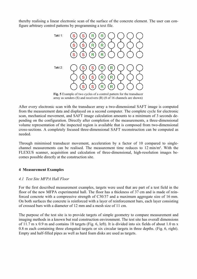
For the first described measurement examples, targets were used that are part of a test field in the floor of the new MFPA experimental hall. The floor has a thickness of 37 cm and is made of rein-forced concrete with a compressive strength of C30/37 and a maximum aggregate size of 16 mm. On both surfaces the concrete is reinforced with a layer of reinforcement bars, each layer consisting of crossed bars with a diameter of 12 mm and a mesh size of 11 cm. The purpose of the test site is to provide targets of simple geometry to compare measurement and imaging methods in a known but real construction environment. The test site has overall dimensions of 11.7 m x 0.9 m and contains 18 targets (Fig. 6, left). It is divided into six fields of about 1.0 m x 0.8 m each containing three elongated targets or six circular targets in three depths. (Fig. 6, right). Empty and half-filled pipes as well as hard foam disks are used as targets.

Fig. 6 Overview of the test site during construction (left); test field R1 with three pipes ∅ 87 mm, divided in an empty part and a part filled with mortar
In the first experiment, a longitudinal transducer with water coupling was used to scan the R1 field containing three pipes of 87 mm diameter, half of the length being filled with mortar, the other half left empty (Fig. 6, right). The transducer has a relatively high frequency spectrum from 180 to 570 kHz in glass and a centre frequency at about 200 kHz in concrete, which qualifies it for high-resolution images in near-surface regions of the concrete. Fig. 7 shows bipolar xy depth sections of the three-dimensional SAFT reconstruction at two differ-ent depths. In the left image, reinforcement bars of the upper layer extending in the x direction are imaged at a depth of z = -68 mm. Their y directed counterparts are shown in the right image at a depth of z = -80 mm. Indications of reconstructed reinforcement bars that have higher acoustical impedance than concrete start with a positive (light) half wave, whereas the indication of the empty part of the pipe that has lower impedance than concrete starts with a negative (dark) half wave. The right image also shows an indication of the topmost of the three pipe targets. This indication be-longs to the empty half of the pipe; the indication becomes stronger at greater depths. Reflexions of the half of the pipe filled with mortar are so small that they do not appear in this image.
Fig 7 Bipolar depth sections of the upper reinforcement layer: reinforcement in x direction at z = -68 mm (left) and in y direction at z = -80 mm (right). The empty part of the uppermost pipe is so visible (arrow). al
The following measurement example was acquired with the single-channel transducer of Fig. 4 at the same test field R1. The mechanical scan of an area of 1.0 m x 0.8 m in a 10 mm x 10 mm grid took four hours, the SAFT reconstruction 77 minutes, and the display 2 minutes. Fig. 8 shows the result of the three-dimensional SAFT reconstruction in three different iso-surface views. The colours of the colour table are changed with depth for better differentiation of object

locations. This iso-surface view gives a good overview of the complete region, but it lacks ampli-tude gradients and is therefore less suited for detailed evaluation. As with every SAFT reconstruc-tion, the images do not show the inner composition of concrete structures directly but rather need to be interpreted. All views in Fig. 8 are displayed as direct output from the reconstruction and evaluation program without any further manual processing. In the images, the empty parts of the pipes are well repro-duced. Uneven indications are caused by shadowing of reinforcement and concrete inhomogenei-ties. The filled parts of the pipes were reconstructed with low contrast and cannot be identified here. The back wall is displayed not as an even plane but jagged due to shadowing and amplitude varia-tions. Some indications of back side reinforcement and of spacers can be distinguished in front of the back wall. It is possible to reconstruct the reinforcement grid of 11 cm from these. Due to the poor near field resolution of these transducers, the front side reinforcement is not imaged. Image noise as well as local reflections would be visible as “clots”, but are rarely seen here because of the good signal-to-noise ratio.
Fig. 8 Result of three-dimenstional SAFT reconstruction of test field R1 in Fig. 6, right, in three different views. The three pipes are marked with arrows.
4.2 Test Specimen with Void and Back Wall Displacement
An additional examination was conducted at the test specimen in Fig. 2. The specimen has dimen-sions of 1.2 m x 0.8 m x 0.2 m and contains a void (rigid foam sphere) of 50 mm diameter and 100 mm cover, and also has a back wall displacement from 200 mm to 150 mm in one of its edges. Measurements were done using the electronic FLEXUS scanner. The transducer array was aligned in x direction, had a track width of 240 mm, and was moved along the y direction. The complete scan covered an area of 240 mm x 720 mm with a scan grid of 20 mm x 10 mm. Measurement and

SAFT reconstruction took 16 minutes, the image display 1 minute. A faster measurement with a measurement time of 2 minutes delivered a slightly deteriorated image quality. The SAFT cross sections of the electronic scans were permanently calculated and combined by the imaging software to form a three-dimensional data set. Right after the measurement, the result could be viewed as the iso-surface view in Fig. 9. Again, no manual processing was applied. The void is both directly imaged and indirectly recognisable by its back wall shadowing; the back wall displacement is also clearly visible.
Fig. 9 Result of three-dimensional sliced SAFT reconstruction of measurement using the electronic FLEXUS array at the test specimen with void of 50 mm diameter and back wall displacement
5 Prospects
Automated ultrasonic imaging methods offer the possibility to fully image the volume of concrete structures. Depending on measurement conditions, high resolution images can be generated, which show even small built-in parts and faults. Different optimisations for penetration depth and scan-ning speed are offered by single-channel transducers and the multi-channel FLEXUS scanner. Work is under way to integrate the advantages of either probe in one device. New application possibilities are opened for civil engineering by automated measurement technolo-gies, as investigations in the areas of quality assurance and defect detection become economically feasible. Critical regions can be comprehensively examined after construction and for periodic test-ing of e. g. bridges [4]. In perspective, such investigations can become standard practice and can help to ensure building quality during construction and operation. Other applications of automated measurement techniques are under development. The feasibility of tomographic flaw imaging in concrete columns has already been shown [5]. Even shorter measure-ment times can be achieved with the employment of air-coupled ultrasound [6, 7].
Acknowledgement
The automated imaging system has been developed within the framework of the FOR384 and USSTAT projects, which were supported by the Deutsche Forschungsgemeinschaft (German re-search council), and the within the framework of the PRO INNO II joint project FLEXUS sup-ported by BMWi. In addition, the authors like to thank Mr. U. Tümmler (MFPA Weimar), Mr. D. Ilse und Dr. L. Bühling (Ing.-Büro Dr. Hillger) for their collaboration on the measurement sys-tem. Mr. U. Tümmler has also assisted in the discussed measurements.

References
[1] Ch. Maierhofer, H.-W. Reinhardt, G. Dobmann: Non-destructive Evaluation of Reinforced Concrete Structures. Cambridge: Woodhead (to be published 2010).
[2] M. Krause, B. Milmann, F. Mielentz, D. Streicher, B. Redmer, K. Mayer, K.-J. Langenberg, M. Schickert: Ultrasonic Imaging Methods for Investigation of Post-tensioned Concrete Structures: A Study of Interfaces at Artificial Grouting Faults and Its Verification. Journal of Nondestructive Evaluation, Special Issue on Acoustic and Electromag. Nondestr. Eval. of Concrete Structures, 27 (2008) pp. 67–82.
[3] M. Schickert, M. Krause, W. Müller: Ultrasonic Imaging of Concrete Elements Using Recon-struction by Synthetic Aperture Focusing Technique. Journal of Materials in Civil Engineer-ing 15 (2003) 235–246.
[4] M. Krause, H. Wiggenhauser, J. Krieger: NDE of a Post Tensioned Concrete Bridge Girder Using Ultrasonic Pulse Echo and Impact Echo; Structural Materials Technology (SMT): NDE/NDT for Highways and Bridges, Cincinatti, Ohio, 10.–13.9.2002. Columbus, Ohio: American Society for Nondestructive Testing (ASNT), 2002.
[5] M. Schickert: Progress in Ultrasonic Imaging of Concrete. Materials and Structures, Special issue on Concrete Science and Engineering, 38 (2005) 807–815.
[6] B. Gräfe, M. Krause: Basic Investigation with Air-Coupled Ultrasonic Echo for Concrete Elements. 6th International symposium on NDT in Civil Engineering (NDT-CE), St. Louis, Missouri, 14.–18.8.2006. Columbus, Ohio: American Society for Nondestructive Testing, 2006.
[7] M. Schickert, U. Tümmler, L. Bühling: Rapid Scanning Approaches for Ultrasonic Imaging of Concrete. 9th European Conference on NDT (ECNDT), Berlin, 25.–29.9.2006. Berlin: Deutsche Gesellschaft für Zerstörungsfreie Prüfung (DGZfP), 2006, CD-ROM, 1–8.