Embed Size (px)
Citation preview
Scanning Imaging Photometer System
(SIPS)
Ionospheric Space Weather Sensor
!
Chad Fish, Geoff Crowley, Irfan Azeem, Marcin Pilinski!ASTRA LLC., Boulder, CO!
John Noto, Mike Migliosi!Scientific Solutions, Inc.!North Chelmsford, MA!
Rick Doe, Kyle Leveque!SRI International!Menlo Park, CA !
ASTRA • www.astraspace.net • 303-993-8039 • [email protected] © 2015 Atmospheric & Space Technology Research Associates, LLC
• Atmospheric & Space Technology Research Associates LLC
• Small business (Boulder, CO)
• Specializing in Solar-Terrestrial research/applications/products
• Current/recent customers:
• AFRL
• AFOSR
• ONR
• NRL
• NASA
• NSF
• JHU-APL
• Aerospace Corp.
• Los Alamos National Laboratory
• Various universities
Science! Technology !
Applications! Bringing It All Together!
"
"
"
"
"
"
"
"
"
"
"
"
"
"
"
"
"
"
"
"
"
"
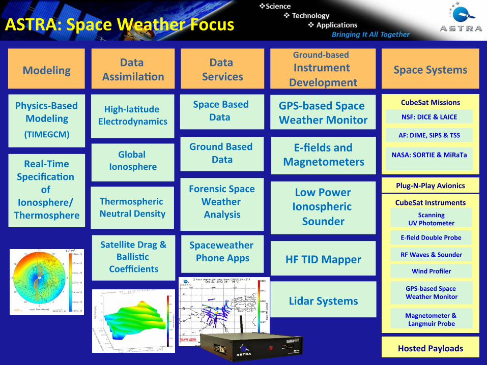
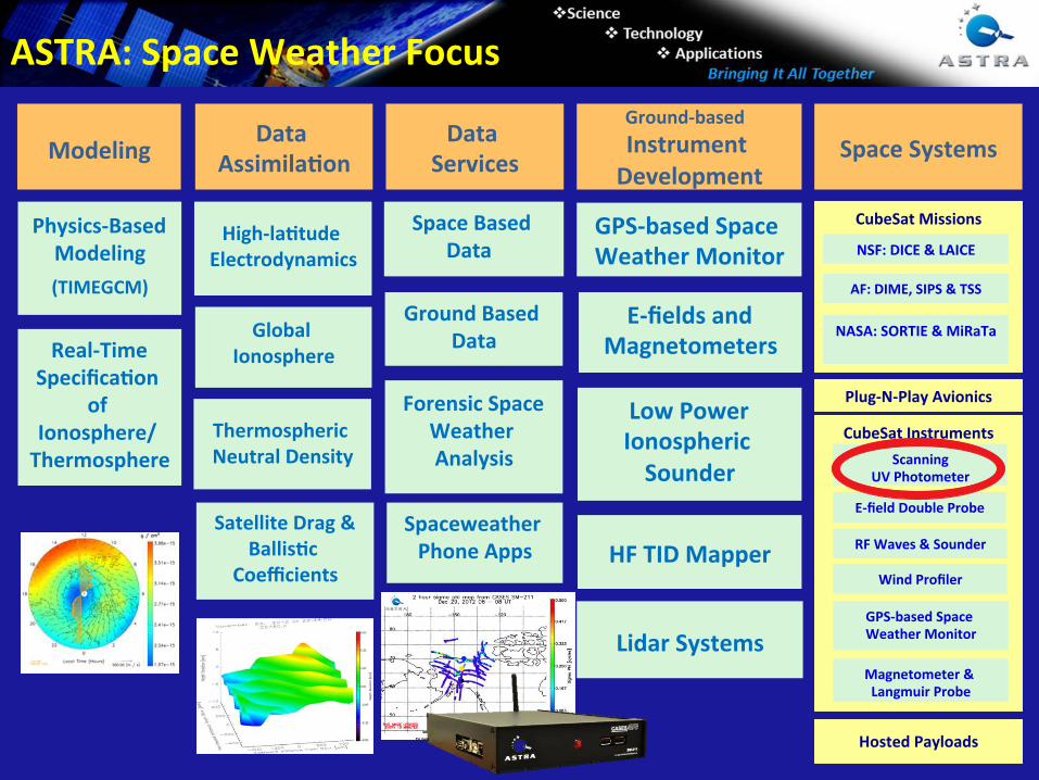
Spaceweather
Phone Apps
Modeling
Ground‐based
Instrument
Development
Data
Assimila=on
Data
Services
Global
Ionosphere
Physics‐Based Modeling
(TIMEGCM)
High‐la=tude
Electrodynamics
Space Based
Data
Ground Based
Data
HF TID Mapper
Space Systems
GPS‐based Space
Weather Monitor
CubeSat Instruments
Scanning
UV Photometer
E‐field Double Probe
GPS‐based Space
Weather Monitor
RF Waves & Sounder
Wind Profiler
CubeSat Missions
NASA: SORTIE & MiRaTa
AF: DIME, SIPS & TSS
NSF: DICE & LAICE
Plug‐N‐Play Avionics
Hosted Payloads
ASTRA: Space Weather Focus
Thermospheric
Neutral Density
Satellite Drag &
Ballis=c
Coefficients
Lidar Systems
E‐fields and
Magnetometers
Forensic Space
Weather
Analysis
Real‐Time
Specifica=on
of
Ionosphere/
Thermosphere
Low Power
Ionospheric
Sounder
Magnetometer &
Langmuir Probe
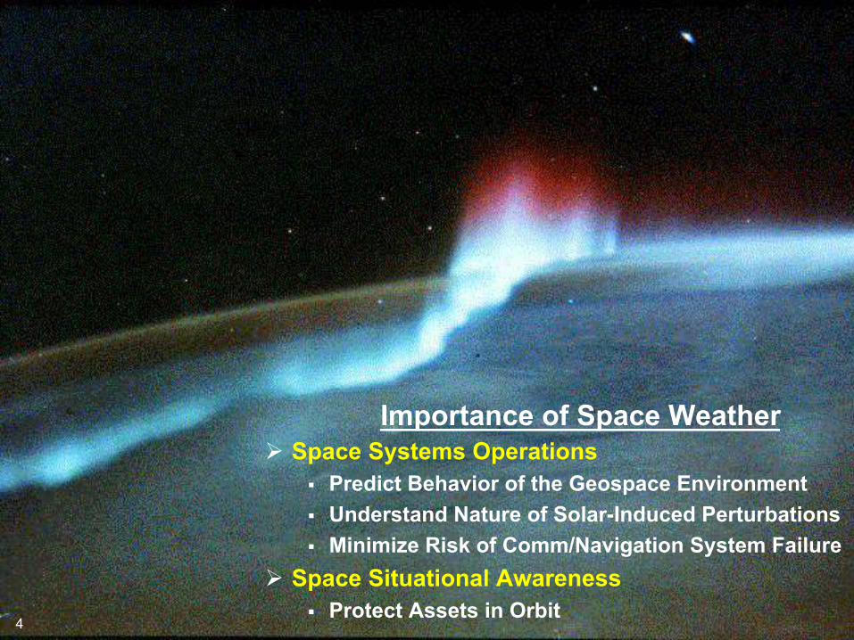
Importance of Space Weather
Space Systems Operations
Predict Behavior of the Geospace Environment
Understand Nature of Solar-Induced Perturbations
Minimize Risk of Comm/Navigation System Failure
Space Situational Awareness
Protect Assets in Orbit 4
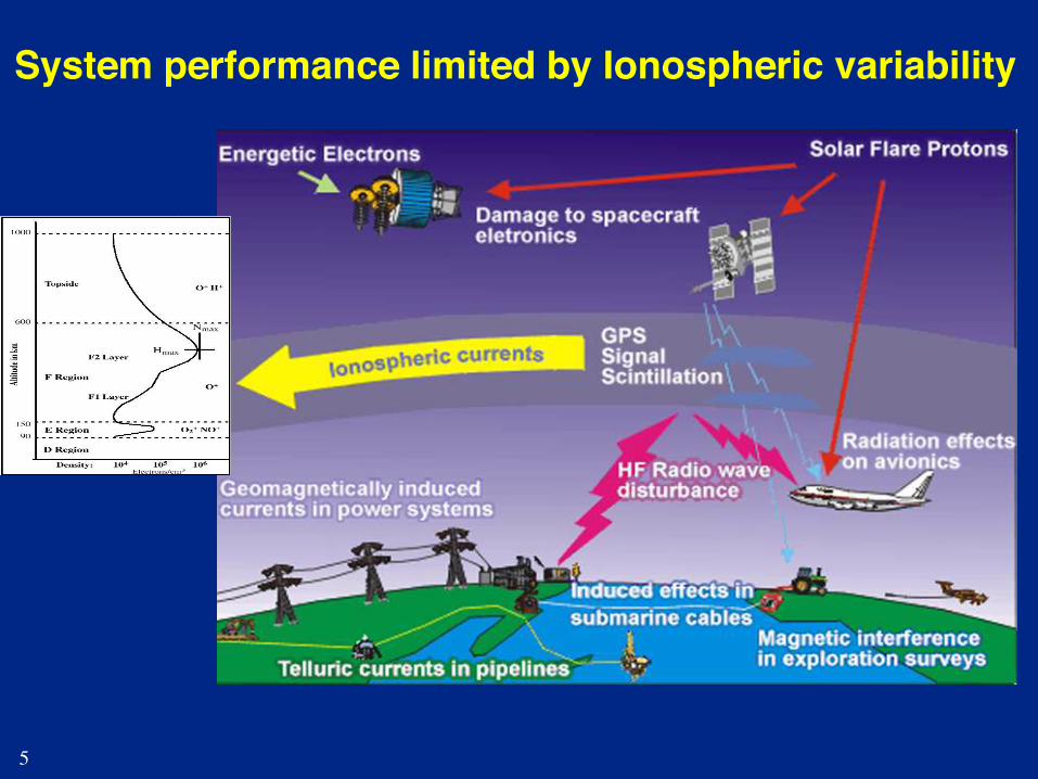
System performance limited by Ionospheric variability!
5
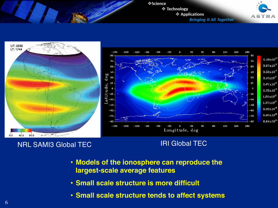
NRL SAMI3 Global TEC" IRI Global TEC"
• Models of the ionosphere can reproduce the largest-scale average features !
• Small scale structure is more difficult!
• Small scale structure tends to affect systems!6
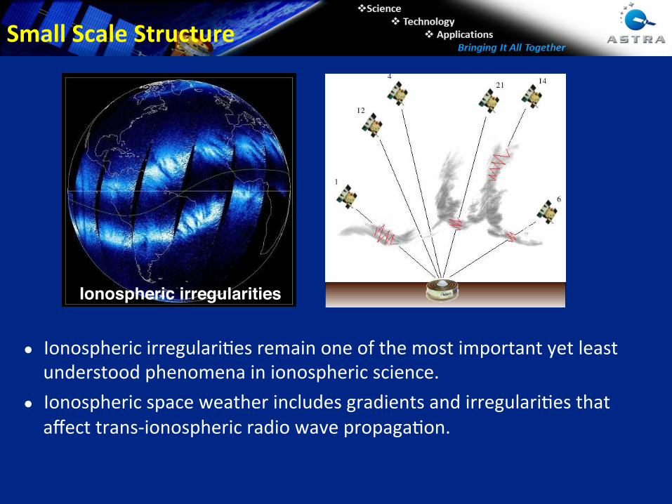
● Ionospheric irregulari1es remain one of the most important yet least
understood phenomena in ionospheric science.
● Ionospheric space weather includes gradients and irregulari1es that
affect trans‐ionospheric radio wave propaga1on.
Ionospheric irregularities!
Small Scale Structure
"
"
"
"
"
"
"
"
"
"
"
"
"
"
"
"
"
"
"
"
"
"
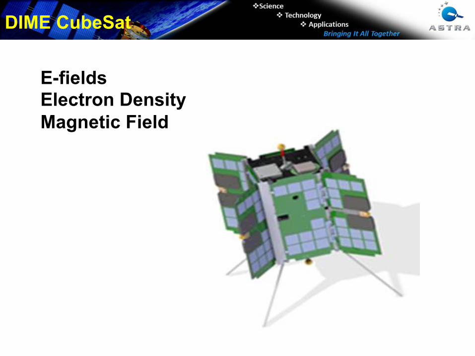
DIME CubeSat
E-fields
Electron Density
Magnetic Field
"
"
"
"
"
"
"
"
"
"
"
"
"
"
"
"
"
"
"
"
"
"
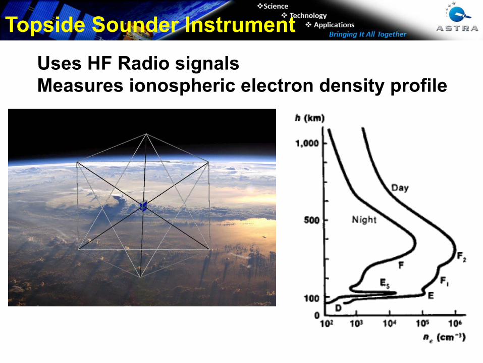
Topside Sounder Instrument
Uses HF Radio signals
Measures ionospheric electron density profile
"
"
"
"
"
"
"
"
"
"
"
"
"
"
"
"
"
"
"
"
"
"
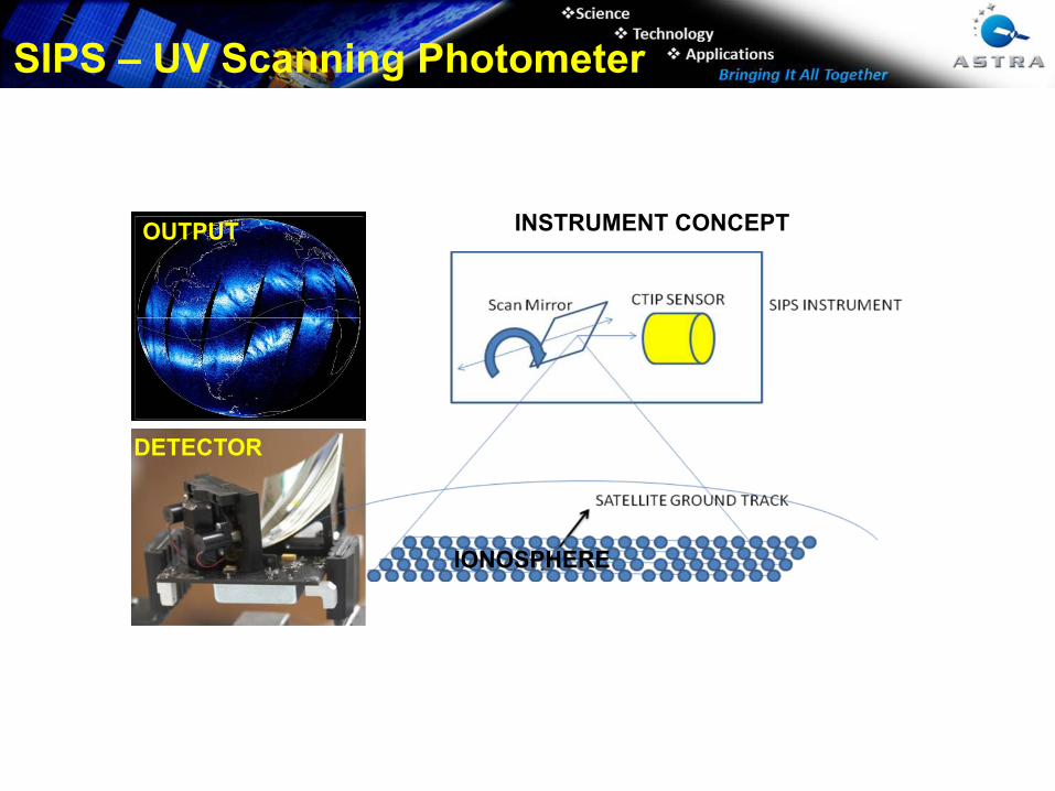
OUTPUT
DETECTOR
INSTRUMENT CONCEPT
IONOSPHERE
SIPS – UV Scanning Photometer
"
"
"
"
"
"
"
"
"
"
"
"
"
"
"
"
"
"
"
"
"
"
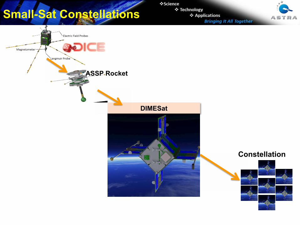
Constellation
ASSP Rocket
Payloads
DIMESat
SDL/14-112
Small-Sat Constellations
ASSP Rocket!
"
"
"
"
"
"
"
"
"
"
"
"
"
"
"
"
"
"
"
"
"
"
Spaceweather
Phone Apps
Modeling
Ground‐based
Instrument
Development
Data
Assimila=on
Data
Services
Global
Ionosphere
Physics‐Based Modeling
(TIMEGCM)
High‐la=tude
Electrodynamics
Space Based
Data
Ground Based
Data
HF TID Mapper
Space Systems
GPS‐based Space
Weather Monitor
CubeSat Instruments
Scanning
UV Photometer
E‐field Double Probe
GPS‐based Space
Weather Monitor
RF Waves & Sounder
Wind Profiler
CubeSat Missions
NASA: SORTIE & MiRaTa
AF: DIME, SIPS & TSS
NSF: DICE & LAICE
Plug‐N‐Play Avionics
Hosted Payloads
ASTRA: Space Weather Focus
Thermospheric
Neutral Density
Satellite Drag &
Ballis=c
Coefficients
Lidar Systems
E‐fields and
Magnetometers
Forensic Space
Weather
Analysis
Real‐Time
Specifica=on
of
Ionosphere/
Thermosphere
Low Power
Ionospheric
Sounder
Magnetometer &
Langmuir Probe
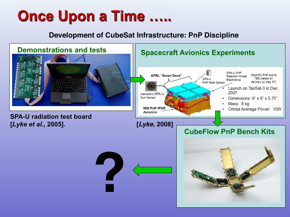
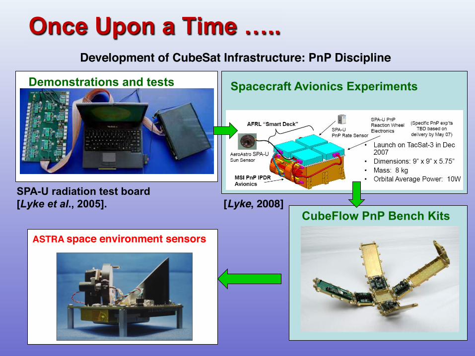
Once Upon a Time …..
CubeFlow PnP Bench Kits
Demonstrations and tests
SPA-U radiation test board
[Lyke et al., 2005].
Spacecraft Avionics Experiments
Development of CubeSat Infrastructure: PnP Discipline!
[Lyke, 2008]"
?!
Once Upon a Time …..
CubeFlow PnP Bench Kits
Demonstrations and tests
SPA-U radiation test board
[Lyke et al., 2005].
Spacecraft Avionics Experiments
Development of CubeSat Infrastructure: PnP Discipline!
[Lyke, 2008]"
ASTRA space environment sensors!
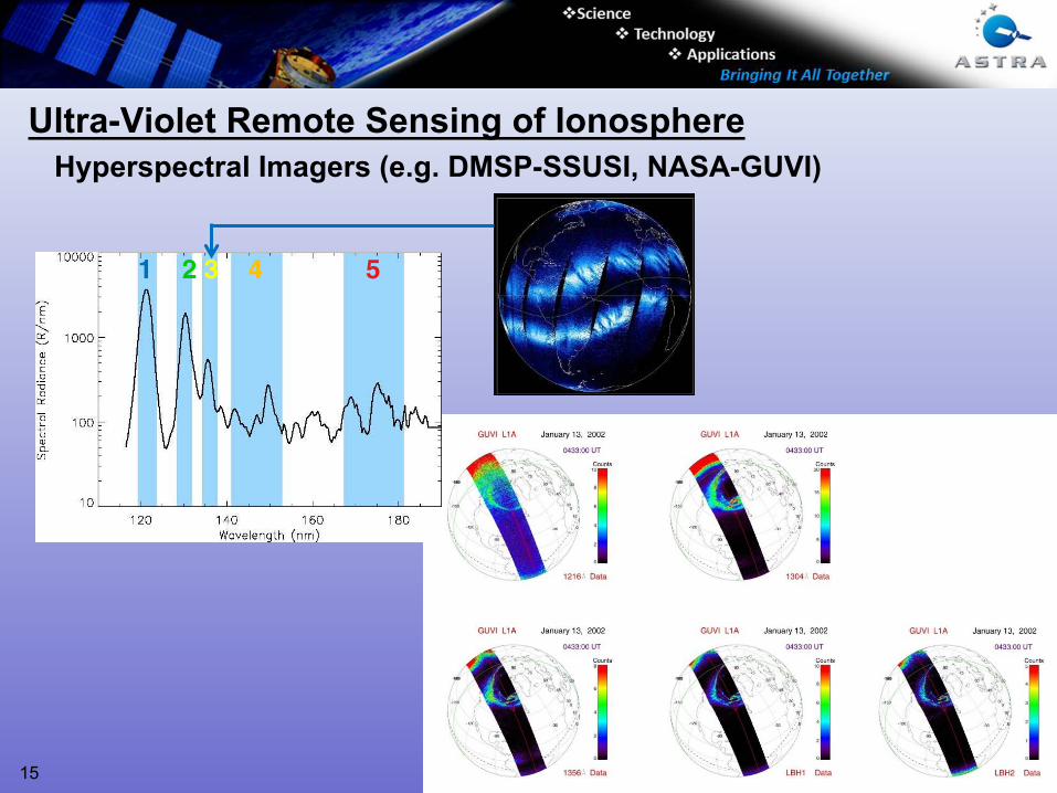
Ultra-Violet Remote Sensing of Ionosphere
Hyperspectral Imagers (e.g. DMSP-SSUSI, NASA-GUVI)
1 2 3 4 5 !
15
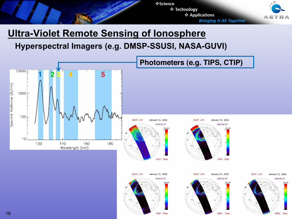
Ultra-Violet Remote Sensing of Ionosphere
Hyperspectral Imagers (e.g. DMSP-SSUSI, NASA-GUVI)
1 2 3 4 5 !
16
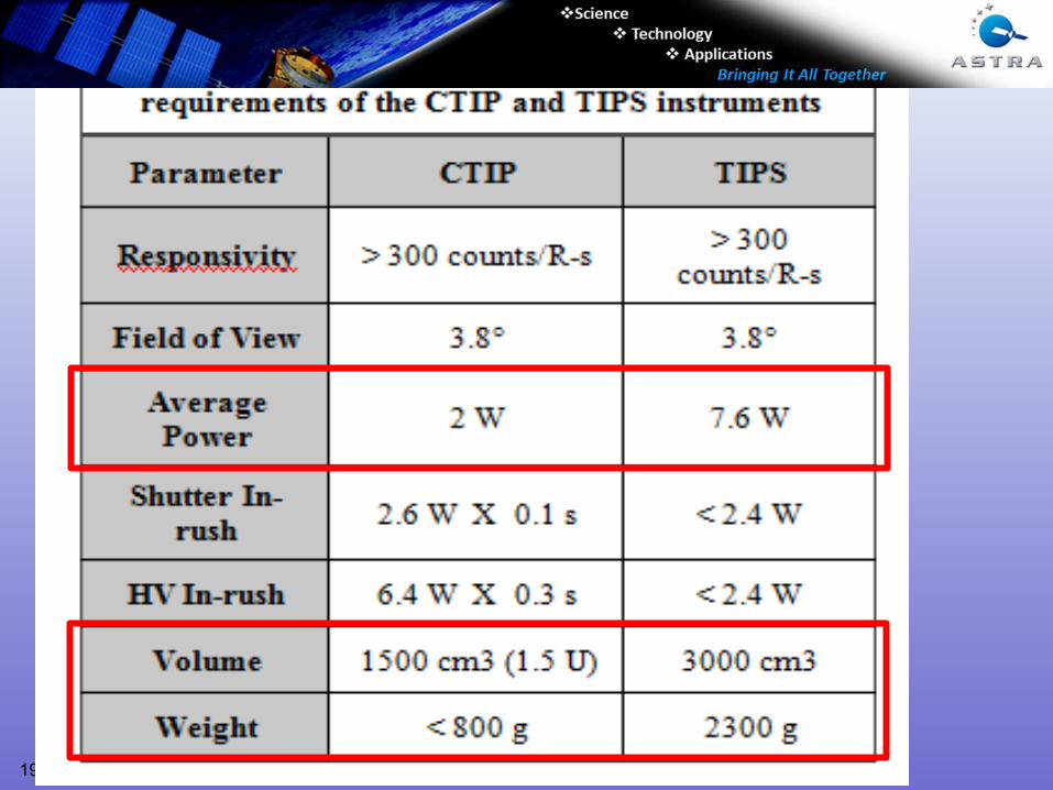
Photometers (e.g. TIPS, CTIP)"
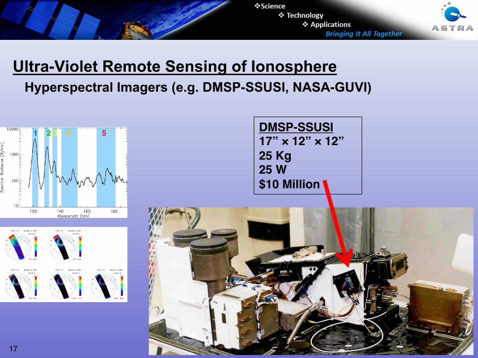
Ultra-Violet Remote Sensing of Ionosphere
Hyperspectral Imagers (e.g. DMSP-SSUSI, NASA-GUVI)
1 2 3 4 5 !
DMSP-SSUSI!17” × 12” × 12”!25 Kg!25 W!$10 Million!
17
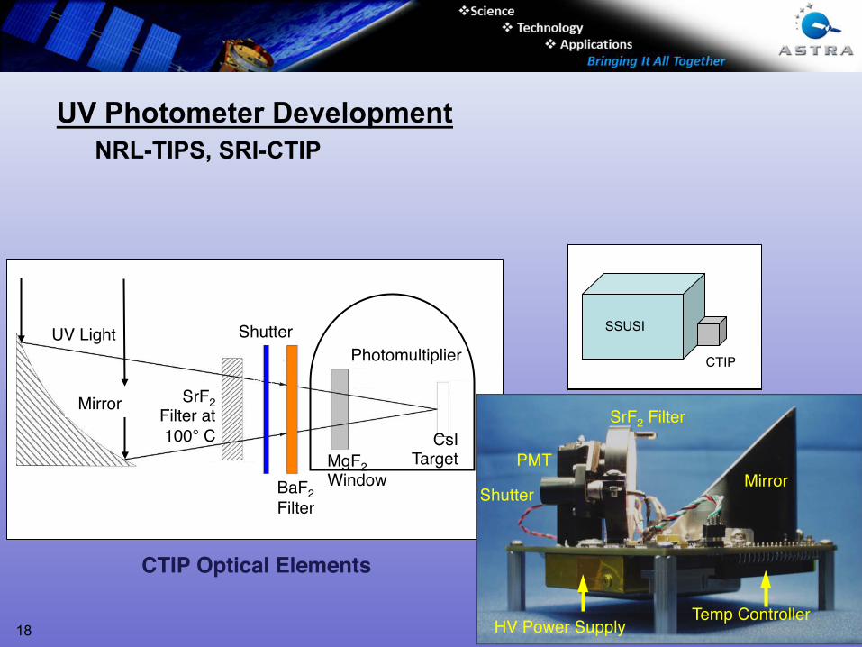
UV Photometer Development
NRL-TIPS, SRI-CTIP
UV Light"
Photomultiplier"
!
BaF2"
Filter"
Solenoid"Operated "
BaF2"
Filter"SrF2"
Filter at"
100° C"
Shutter"
Hamamatsu R7511 "
Hamamatsu R7511 "Hamamat
su R7511 !
"
Mirror"
MgF2"
Window!
Hamamatsu R7511 " Hamam
atsu
R7511 "
CsI"Target!
CTIP Optical Elements!
HV PS !
SrF2 Filter "
PMT"
Shutter"Mirror "
HV Power Supply "Temp Controller "
CTIP!4” × 4” × 4”!2.5 Kg!2.5 W!$1 Million!
SSUSI"
CTIP"
18
19
"
"
"
"
"
"
"
"
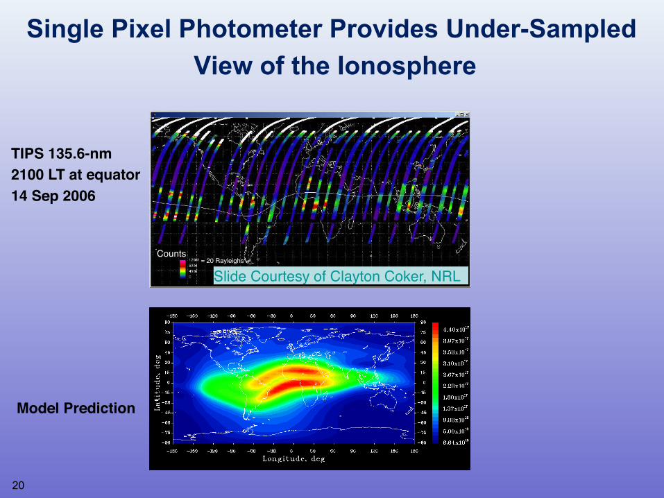
Single Pixel Photometer Provides Under-Sampled
View of the Ionosphere
TIPS 135.6-nm !
2100 LT at equator!
14 Sep 2006!
Counts"= 20 Rayleighs"
Slide Courtesy of Clayton Coker, NRL"
Model Prediction!
20
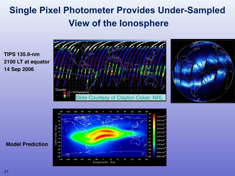
Single Pixel Photometer Provides Under-Sampled
View of the Ionosphere
TIPS 135.6-nm !
2100 LT at equator!
14 Sep 2006!
Counts"= 20 Rayleighs"
Slide Courtesy of Clayton Coker, NRL"
Model Prediction!
21
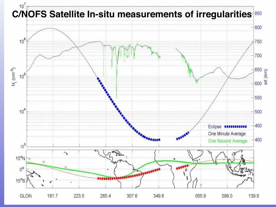
C/NOFS Satellite In-situ measurements of irregularities!
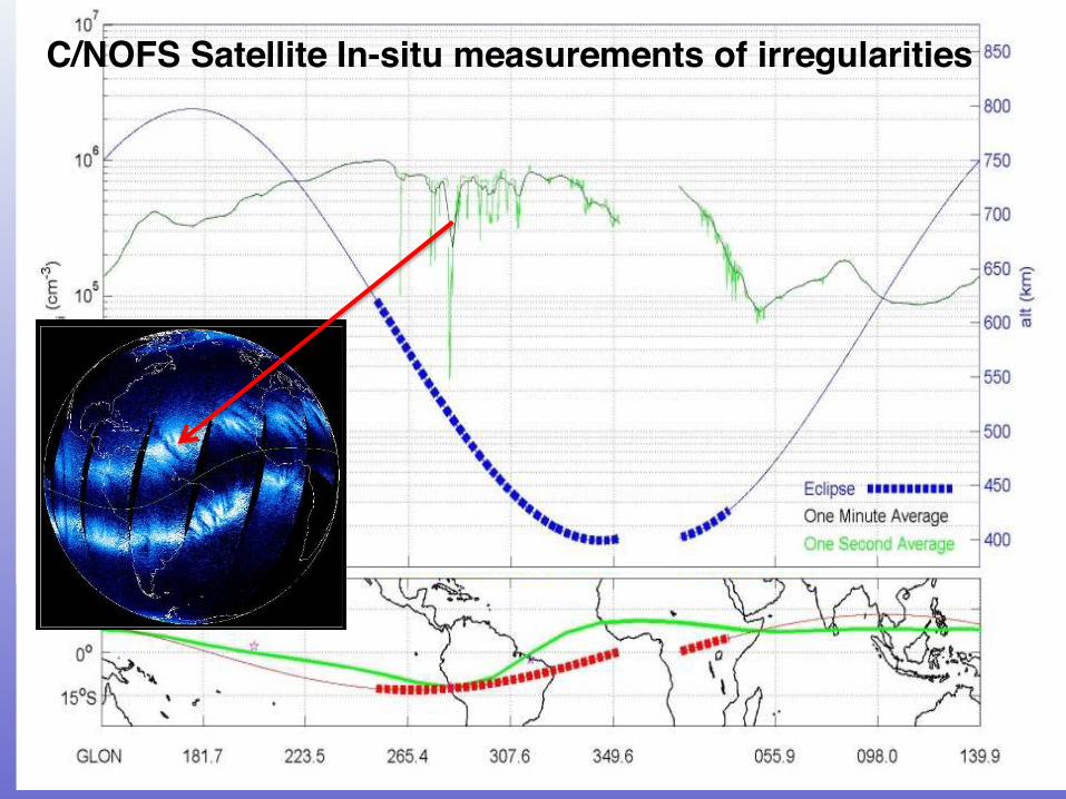
C/NOFS Satellite In-situ measurements of irregularities!
24
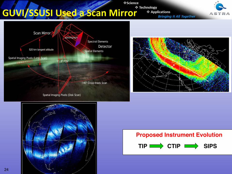
TIP! CTIP! SIPS!
Proposed Instrument Evolution!
GUVI/SSUSI Used a Scan Mirror
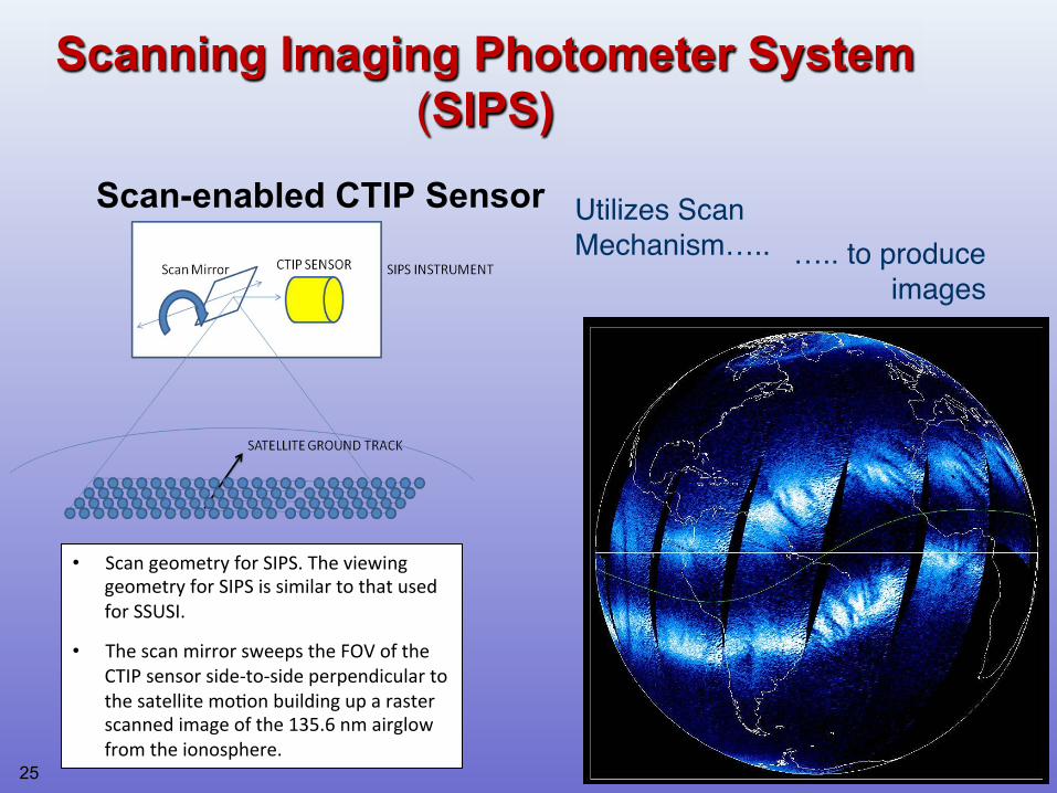
Scanning Imaging Photometer System
(SIPS)
Utilizes Scan
Mechanism….." ….. to produce
images"
Scan-enabled CTIP Sensor
• Scan geometry for SIPS. The viewing
geometry for SIPS is similar to that used
for SSUSI.
• The scan mirror sweeps the FOV of the
CTIP sensor side‐to‐side perpendicular to
the satellite mo1on building up a raster
scanned image of the 135.6 nm airglow
from the ionosphere.
25
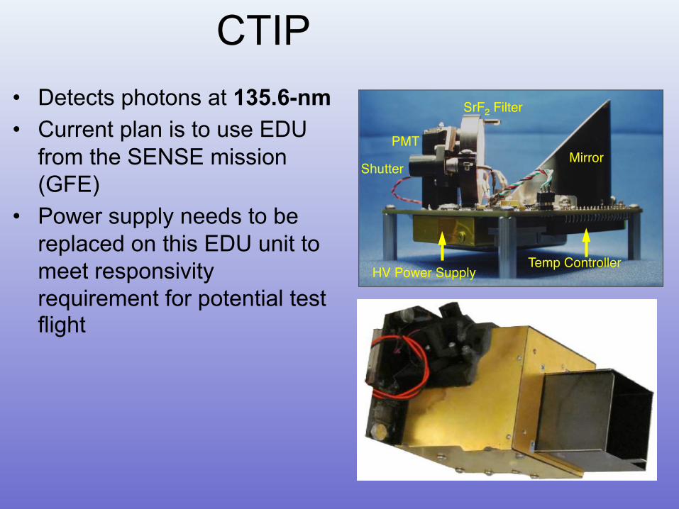
CTIP
• Detects photons at 135.6-nm
• Current plan is to use EDU
from the SENSE mission
(GFE)
• Power supply needs to be
replaced on this EDU unit to
meet responsivity
requirement for potential test flight
HV PS !
SrF2 Filter "
PMT"
Shutter"Mirror "
HV Power Supply "Temp Controller "
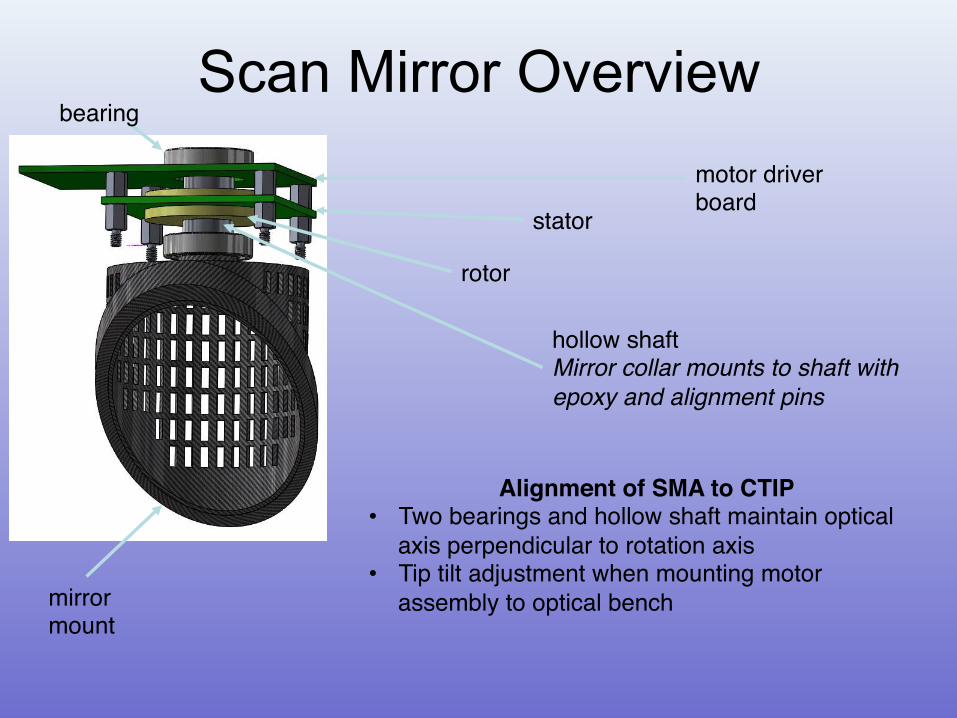
Scan Mirror Overview bearing"
rotor"
stator"
motor driver board"
mirror mount"
hollow shaft"Mirror collar mounts to shaft with
epoxy and alignment pins!
Alignment of SMA to CTIP"• Two bearings and hollow shaft maintain optical
axis perpendicular to rotation axis"• Tip tilt adjustment when mounting motor
assembly to optical bench"
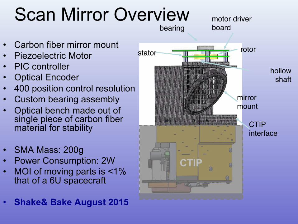
Scan Mirror Overview
• Carbon fiber mirror mount
• Piezoelectric Motor
• PIC controller
• Optical Encoder
• 400 position control resolution
• Custom bearing assembly
• Optical bench made out of single piece of carbon fiber material for stability
• SMA Mass: 200g
• Power Consumption: 2W
• MOI of moving parts is <1% that of a 6U spacecraft
• Shake& Bake August 2015
bearing"
rotor"
motor driver board"
mirror mount"
hollow shaft"
stator"
CTIP interface"
CTIP
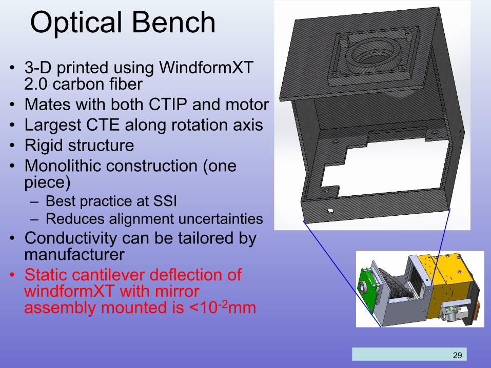
Optical Bench
• 3-D printed using WindformXT 2.0 carbon fiber
• Mates with both CTIP and motor
• Largest CTE along rotation axis
• Rigid structure
• Monolithic construction (one piece) – Best practice at SSI
– Reduces alignment uncertainties
• Conductivity can be tailored by manufacturer
• Static cantilever deflection of windformXT with mirror assembly mounted is <10-2mm
29
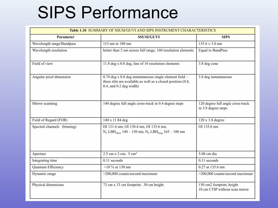
SIPS Performance Table 1.10 SUMMARY OF SSUSI/GUVI AND SIPS INSTRUMENT CHARACTERISTICS
Parameter SSUSI/GUVI SIPS
Wavelength range/Bandpass 115 nm to 180 nm 135.6 ± 3.0 nm
Wavelength resolution better than 2 nm across full range, 160 resolution elements Equal to BandPass
Field of view 11.8 deg x 0.8 deg, line of 16 resolution elements 3.8 deg cone
Angular pixel dimension 0.74 deg x 0.8 deg instantaneous single element field –
three slits are available as well as a closed position (0.8,
0.4, and 0.2 deg width)
3.8 deg instantaneous
Mirror scanning 140 degree full angle cross-track in 0.4 degree steps 120 degree full angle cross-track
in 3.8 degree steps
Field of Regard (FOR) 140 x 11.84 deg 120 x 3.8 degree
Spectral channels (binning) HI 121.6 nm, OI 130.4 nm, OI 135.6 nm, N2 LBHshort 140 – 150 nm, N2 LBHlong 165 – 180 nm
OI 135.6 nm
Aperture 2.5 cm x 2 cm; 5 cm2 5.08 cm dia
Integrating time 0.11 seconds 0.11 seconds
Quantum Efficiency >10 % at 130 nm 0.27 at 135.6 nm
Dynamic range >200,000 counts/second maximum >200,000 counts/second maximum
Physical dimensions 73 cm x 33 cm footprint; 30 cm height 150 cm2 footprint, height 10 cm CTIP without scan mirror
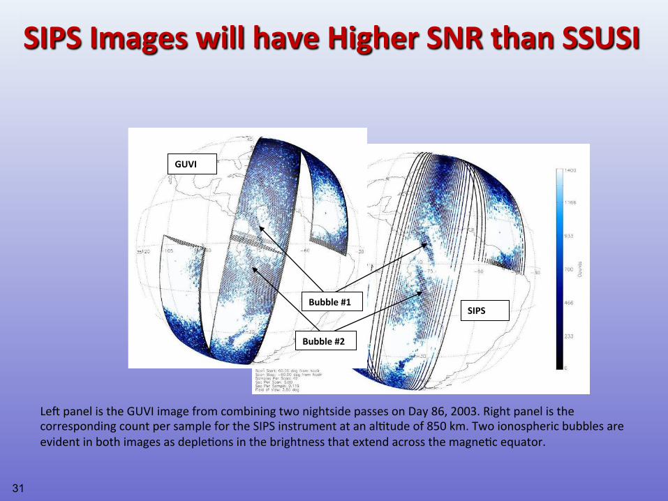
Bubble #2
Bubble #1
GUVI
SIPS
LeJ panel is the GUVI image from combining two nightside passes on Day 86, 2003. Right panel is the
corresponding count per sample for the SIPS instrument at an al1tude of 850 km. Two ionospheric bubbles are
evident in both images as deple1ons in the brightness that extend across the magne1c equator.
"
SIPS Images will have Higher SNR than SSUSI
31
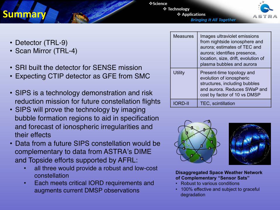
Measures Images ultraviolet emissions from nightside ionosphere and aurora; estimates of TEC and
aurora; identifies presence, location, size, drift, evolution of
plasma bubbles and aurora
Utility Present-time topology and evolution of ionospheric structures, including bubbles
and aurora. Reduces SWaP and cost by factor of 10 vs DMSP
IORD-II TEC, scintillation
Disaggregated Space Weather Network of Complementary “Sensor Sats” • Robust to various conditions
• 100% effective and subject to graceful degradation
• Detector (TRL-9)"• Scan Mirror (TRL-4)"
"
• SRI built the detector for SENSE mission"
• Expecting CTIP detector as GFE from SMC"
• SIPS is a technology demonstration and risk
reduction mission for future constellation flights"• SIPS will prove the technology by imaging
bubble formation regions to aid in specification
and forecast of ionospheric irregularities and their effects"
• Data from a future SIPS constellation would be complementary to data from ASTRAʼs DIME
and Topside efforts supported by AFRL: "• all three would provide a robust and low-cost
constellation "• Each meets critical IORD requirements and
augments current DMSP observations"
Summary
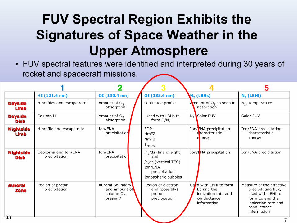
FUV Spectral Region Exhibits the
Signatures of Space Weather in the
Upper Atmosphere • FUV spectral features were identified and interpreted during 30 years of
rocket and spacecraft missions.
HI (121.6 nm) OI (130.4 nm) OI (135.6 nm) N2 (LBHs) N2 (LBHl)
Dayside Limb
H profiles and escape rate1 Amount of O2 absorption1
O altitude profile Amount of O2 as seen in absorption
N2, Temperature
Dayside Disk
Column H Amount of O2 absorption1
Used with LBHs to form O/N2
N2, Solar EUV Solar EUV
Nightside Limb
H profile and escape rate Ion/ENA precipitation
EDP
HmF2
NmF2
Tplasma
Ion/ENA precipitation characteristic
energy
Ion/ENA precipitation characteristic
energy
Nightside Disk
Geocorna and Ion/ENA precipitation
Ion/ENA precipitation
∫ne2ds (line of sight) and
∫nedz (vertical TEC)
Ion/ENA precipitation
Ionospheric bubbles
Ion/ENA precipitation Ion/ENA precipitation
Auroral Zone
Region of proton precipitation
Auroral Boundary and amount of
column O2
present1
Region of electron and (possibly)
proton
precipitation
Used with LBHl to form Eo and the
ionization rate and
conductance
information
Measure of the effective precipitating flux,
used with LBHl to
form Eo and the
ionization rate and conductance
information
1 2 3 4 5 !
7 33