Embed Size (px)
Citation preview
Automated Radioscopic Inspection of Aluminum Die Castings
Domingo Mery
Departamento de Ciencia de la Computación Pontificia Universidad Católica de Chile
Av. Vicuña Mackena 4860(183) Santiago de Chile
Tel: (+562) 354 5820,Fax: (+562) 354 4444, E-mail : [email protected] URL : http://dccplone.ing.puc.cl/dmery/dmery
Abstract Castings produced for the automotive industry are considered important components for overall roadworthiness. To ensure the safety of construction, it is necessary to check every part thoroughly using non-destructive testing. Radioscopy rapidly became the accepted way for controlling the quality of die cast pieces. In this paper the fundamental principles of the automated detection of casting discontinuities are explained. A general automated inspection schema is presented, and several methods that have appeared in the literature in the past twenty years were explained showing the development of this sector in the areas of industry and academia. Finally, advances in the simulation of defects, used for assessing the performance of an inspection method, are outlined. Keywords: Automated inspection, discontinuity detection, aluminum castings, computer vision, X-ray testing, flaw simulation.
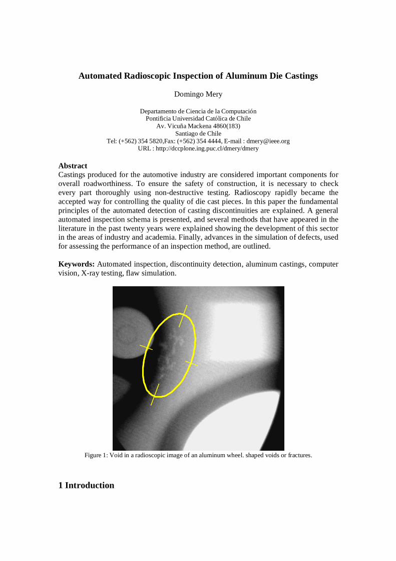
Figure 1: Void in a radioscopic image of an aluminum wheel. shaped voids or fractures.
1 Introduction
Shrinkage as molten metal cools during the manufacture of die-castings, can cause non-homogeneous regions within the work piece. These are manifested, for example, by bubble shaped voids or factures. Voids occur when the liquid metal fails to flow into the die or flows in too slowly, whereas fractures are caused by mechanical stresses when neighboring regions develop different temperature gradients on cooling. Other possible casting discontinuities include inclusions or slag formation. Light-alloy castings produced for the automotive industry, such as wheel rims, steering knuckles and steering gear boxes are considered important components for overall roadworthiness. To ensure the safety of construction, it is necessary to check every part thoroughly. Radioscopy rapidly became the accepted way for controlling the quality of die cast pieces through visual or computer-aided analysis of X-ray images. The purpose of this non-destructive testing (NDT) method is to identify casting discontinuities, which may be located within the piece and thus are undetectable to the naked eye. An example of such discontinuities in a light-alloy wheel is shown in the X-ray image in Fig. 1.
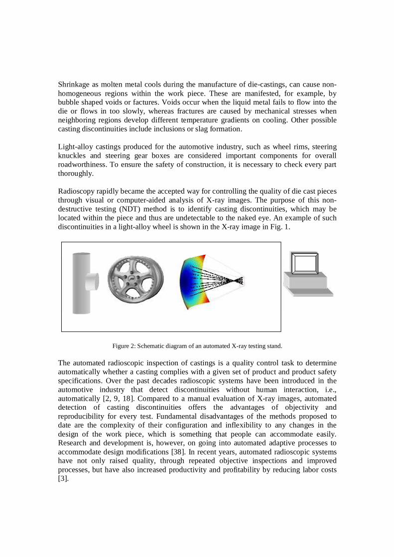
Figure 2: Schematic diagram of an automated X-ray testing stand. The automated radioscopic inspection of castings is a quality control task to determine automatically whether a casting complies with a given set of product and product safety specifications. Over the past decades radioscopic systems have been introduced in the automotive industry that detect discontinuities without human interaction, i.e., automatically [2, 9, 18]. Compared to a manual evaluation of X-ray images, automated detection of casting discontinuities offers the advantages of objectivity and reproducibility for every test. Fundamental disadvantages of the methods proposed to date are the complexity of their configuration and inflexibility to any changes in the design of the work piece, which is something that people can accommodate easily. Research and development is, however, on going into automated adaptive processes to accommodate design modifications [38]. In recent years, automated radioscopic systems have not only raised quality, through repeated objective inspections and improved processes, but have also increased productivity and profitability by reducing labor costs [3].

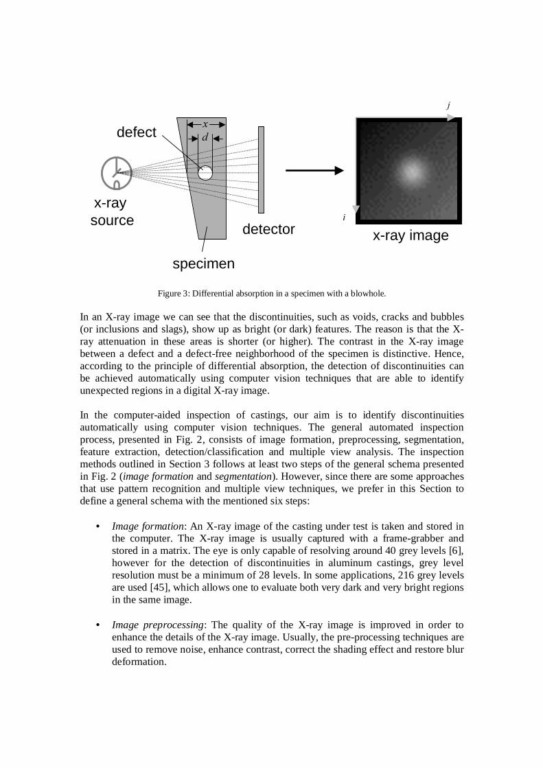
The principle aspects of an automated X-ray inspection unit are shown in Fig. 2. Typically, it comprises the following five steps [42]: i) a manipulator for handling the test piece,ii) an X-ray source, which irradiates the test piece with a conical beam to generate an X-ray image of the test piece,iii) an image intensifier which transforms the invisible X-ray image into a visible one, iv) a CCD camera which records the visible X-ray image,and v) a computer to perform the digital image processing of the X-ray image and to classify the test piece accepting or rejecting it. The computer may also control the manipulator for positioning the test piece in the desired inspection position, although this task is normally performed by a programmable logic controller (PLC). Nowadays, flat amorphous silicon detectors are used as image sensors in some industrial inspection systems [45]. In such detectors, using a semi-conductor, energy from the X-ray is converted directly into an electrical signal (without image intensifier). However, NDT using flat detectors is less feasible due to their higher cost in comparison to image intensifiers. In automated discontinuity detection in die castings the throughput cycle time is principally determined by the mechanical speed. In order to optimize the mechanical cycle, a new concept was presented recently in [49], in which the test object and the X-ray source can be moved simultaneously. This concept gives 30% higher throughput. In this paper, we will discuss the use of computer vision as a tool in the automated radioscopic inspection of aluminum die castings. The paper is organized as follows: Section 2 introduces the reader to the computer vision theory employed when inspecting aluminum castings. Section 3 presents a survey of several of the automated visual inspection approaches adopted for aluminum castings that have been reported since 1985. In order to evaluate the performance of a method that inspects castings, it is convenient to examine simulated data. This evaluation gives the possibility of tuning the parameters of the inspection method and of testing how the method works in critical cases. For this reason, Section 4 is dedicated to the state-of-the-art of discontinuity simulation techniques in castings. Finally, Section 5 concludes and offers suggestions for future research. 2 Computer Vision In X-ray examination, X-ray radiation is passed through the material under test, and a detector senses the radiation intensity attenuated by the material. A discontinuity in the material modifies the expected radiation received by the sensor [13]. This phenomenon, called differential absorption, is illustrated in Fig. 3 where a blowhole with diameter d is located inside of the specimen.
x-raysource
specimen
defect
detector x-ray image
xd
j
i
Figure 3: Differential absorption in a specimen with a blowhole. In an X-ray image we can see that the discontinuities, such as voids, cracks and bubbles (or inclusions and slags), show up as bright (or dark) features. The reason is that the X-ray attenuation in these areas is shorter (or higher). The contrast in the X-ray image between a defect and a defect-free neighborhood of the specimen is distinctive. Hence, according to the principle of differential absorption, the detection of discontinuities can be achieved automatically using computer vision techniques that are able to identify unexpected regions in a digital X-ray image. In the computer-aided inspection of castings, our aim is to identify discontinuities automatically using computer vision techniques. The general automated inspection process, presented in Fig. 2, consists of image formation, preprocessing, segmentation, feature extraction, detection/classification and multiple view analysis. The inspection methods outlined in Section 3 follows at least two steps of the general schema presented in Fig. 2 (image formation and segmentation). However, since there are some approaches that use pattern recognition and multiple view techniques, we prefer in this Section to define a general schema with the mentioned six steps:
• Image formation: An X-ray image of the casting under test is taken and stored in the computer. The X-ray image is usually captured with a frame-grabber and stored in a matrix. The eye is only capable of resolving around 40 grey levels [6], however for the detection of discontinuities in aluminum castings, grey level resolution must be a minimum of 28 levels. In some applications, 216 grey levels are used [45], which allows one to evaluate both very dark and very bright regions in the same image.
• Image preprocessing: The quality of the X-ray image is improved in order to
enhance the details of the X-ray image. Usually, the pre-processing techniques are used to remove noise, enhance contrast, correct the shading effect and restore blur deformation.
• Image segmentation: The digital images is divided into disjoint regions with the
purpose of separating the parts of interest from the rest of the scene. The idea is to segment those regions that correspond to the defects of the specimen.
• Feature extraction: Since some structural parts of the object could be erroneously
segmented as defectively regions in previous step, they are denoted as hypothetical defects. Subsequently, additional steps are required to eliminate the false alarms of the hypothetical defects. The first of these steps is feature extraction, which is centered principally around the measurement of geometric properties and on the intensity characteristics of regions. It is important to know which features provide information about discontinuities. With this end, a feature selection is carried out to find the best subset of the input future set.
• Detection/classification: The extracted (and selected) features of each region are
analyzed in order to detect or classify the existing defects. We will differentiate between the detection of discontinuities and the classification of discontinuities. Detection corresponds to a binary classification, because in the detection problem, the classes that exist are only two: `discontinuities' (defects) or `regular structures' (no defects), whereas the recognition of the type of discontinuity (e.g., voids, cracks, bubbles, inclusions and slags) is known as classification of discontinuity types.
• Multiple view analysis: Some methods use an additional step based on multiple
view geometry. The key idea of the multiple view analysis is to gain more information about a test object by analyzing multiple views taken at different viewpoints. It is a useful and powerful alternative for examining complex objects were uncertainty can lead to misinterpretation, because two or more views of the same object taken from different viewpoints can be used to confirm and improve the diagnostic done by analyzing only one image.
3 A review In this Section, different methods for the automated detection of casting discontinuities using computer vision techniques will be briefly presented. These methods have been described in the literature within the past twenty years and are considered to be the state of the art in this field. One can see that the approaches to detecting can be grouped into three groups: i) approaches where an error-free reference image is used,ii) approaches using pattern recognition, expert systems, artificial neural networks, general filters or multiple view analyzes to make them independent of the position and structure of the test piece,and iii) approaches using computer tomography to make a reconstruction of the cast piece and thereby detect discontinuities. Since the industrial use of computer tomography for the inspection of die cast parts for the automotive industry is currently limited to the areas of materials research and development as well as to the inspection of especially
important and expensive parts1, we limit this review to approaches of the i) and ii) only. Extended reviews of existing approaches (published before 2003) of automated discontinuity detection in aluminum castings can be found in [43, 30].
xy x-y e
IntegrationIntegration FilterpFilterp DetectionDetection
pPosition p
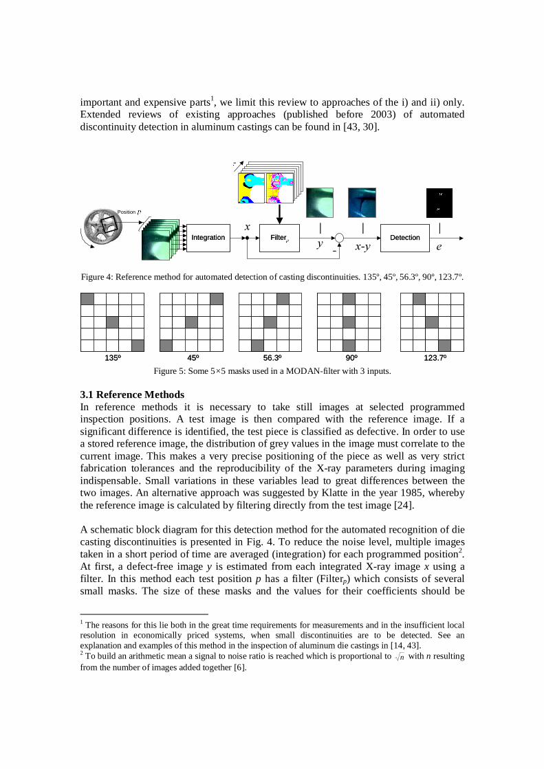
Figure 4: Reference method for automated detection of casting discontinuities. 135º, 45º, 56.3º, 90º, 123.7º.
135º 45º 56.3º 90º 123.7º135º 45º 56.3º 90º 123.7º
Figure 5: Some 5×5 masks used in a MODAN-filter with 3 inputs. 3.1 Reference Methods In reference methods it is necessary to take still images at selected programmed inspection positions. A test image is then compared with the reference image. If a significant difference is identified, the test piece is classified as defective. In order to use a stored reference image, the distribution of grey values in the image must correlate to the current image. This makes a very precise positioning of the piece as well as very strict fabrication tolerances and the reproducibility of the X-ray parameters during imaging indispensable. Small variations in these variables lead to great differences between the two images. An alternative approach was suggested by Klatte in the year 1985, whereby the reference image is calculated by filtering directly from the test image [24]. A schematic block diagram for this detection method for the automated recognition of die casting discontinuities is presented in Fig. 4. To reduce the noise level, multiple images taken in a short period of time are averaged (integration) for each programmed position2. At first, a defect-free image y is estimated from each integrated X-ray image x using a filter. In this method each test position p has a filter (Filterp) which consists of several small masks. The size of these masks and the values for their coefficients should be
1 The reasons for this lie both in the great time requirements for measurements and in the insufficient local resolution in economically priced systems, when small discontinuities are to be detected. See an explanation and examples of this method in the inspection of aluminum die castings in [14, 43]. 2 To build an arithmetic mean a signal to noise ratio is reached which is proportional to n with n resulting from the number of images added together [6].
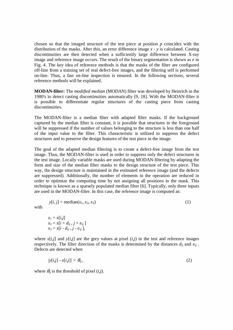
chosen so that the imaged structure of the test piece at position p coincides with the distribution of the masks. After this, an error difference image x - y is calculated. Casting discontinuities are then detected when a sufficiently large difference between X-ray image and reference image occurs. The result of the binary segmentation is shown as e in Fig. 4. The key idea of reference methods is that the masks of the filter are configured off-line from a training set of real defect-free images, and the filtering self is performed on-line. Thus, a fast on-line inspection is ensured. In the following sections, several reference methods will be explained. MODAN-filter: The modified median (MODAN) filter was developed by Heinrich in the 1980's to detect casting discontinuities automatically [9, 18]. With the MODAN-filter it is possible to differentiate regular structures of the casting piece from casting discontinuities. The MODAN-filter is a median filter with adapted filter masks. If the background captured by the median filter is constant, it is possible that structures in the foreground will be suppressed if the number of values belonging to the structure is less than one half of the input value to the filter. This characteristic is utilized to suppress the defect structures and to preserve the design features of the test piece in the image. The goal of the adapted median filtering is to create a defect-free image from the test image. Thus, the MODAN-filter is used in order to suppress only the defect structures in the test image. Locally variable masks are used during MODAN-filtering by adapting the form and size of the median filter masks to the design structure of the test piece. This way, the design structure is maintained in the estimated reference image (and the defects are suppressed). Additionally, the number of elements in the operation are reduced in order to optimize the computing time by not assigning all positions in the mask. This technique is known as a sparsely populated median filter [6]. Typically, only three inputs are used in the MODAN-filter. In this case, the reference image is computed as:
y[i, j] = median(x1, x2, x3) (1) with
x1 = x[i,j] x2 = x[i + dij , j + eij ] x3 = x[i - dij , j - eij ],
where x[i,j] and y[i,j ] are the grey values at pixel (i,j) in the test and reference images respectively. The filter direction of the masks is determined by the distances dij and eij . Defects are detected when
|y[i,j ] - x[i,j ]| > θij , (2)
where θij is the threshold of pixel (i,j).
i
j
dij1 dij2eij2eij1
x[i,j]
i
j
y[i,j]
median
bij1
bij2
Test imageReferenceimage
aij2aij1
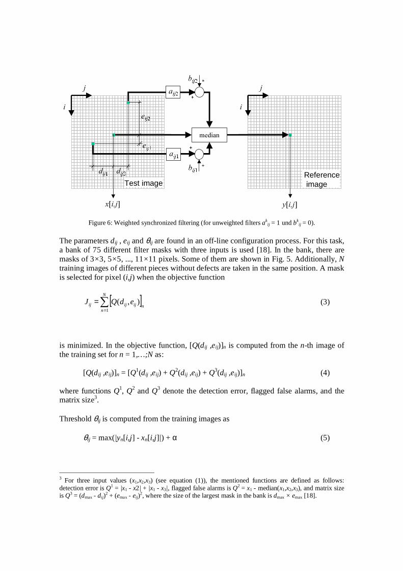
Figure 6: Weighted synchronized filtering (for unweighted filters akij = 1 und bk
ij = 0). The parameters dij , eij and θij are found in an off-line configuration process. For this task, a bank of 75 different filter masks with three inputs is used [18]. In the bank, there are masks of 3×3, 5×5, ..., 11×11 pixels. Some of them are shown in Fig. 5. Additionally, N training images of different pieces without defects are taken in the same position. A mask is selected for pixel (i,j) when the objective function
[ ]∑=
=N
nnijijij edQJ
1
),( (3)
is minimized. In the objective function, [Q(dij ,eij)]n is computed from the n-th image of the training set for n = 1,…;N as:
[Q(dij ,eij)]n = [Q1(dij ,eij) + Q2(dij ,eij) + Q3(dij ,eij)]n (4) where functions Q1, Q2 and Q3 denote the detection error, flagged false alarms, and the matrix size3. Threshold θij is computed from the training images as
θij = max(|yn[i,j ] - xn[i,j ]|) + α (5)
3 For three input values (x1,x2,x3) (see equation (1)), the mentioned functions are defined as follows: detection error is Q1 = |x1 - x2| + |x1 - x3|, flagged false alarms is Q2 = x1 - median(x1,x2,x3), and matrix size is Q3 = (dmax - dij)
2 + (emax - eij)2, where the size of the largest mask in the bank is dmax × emax [18].

With α = 0 we ensure that no false alarm is flagged in all training images. However, it is convenient to set α > 0 to give a larger confidence region. Thus, once the mask is selected, the error-free reference image is estimated on-line using (1) when condition (2) is satisfied. Signal synchronized filter: Hecker developed the signal synchronized filter in [16] to calculate the background image function. This method generalizes the equation used for the MODAN-filter (1) according to Fig. 6. 3 The estimation of the parameters of this filter can be formulated as an optimization problem that minimizes an objective function that considers around N = 20 representative images per position of the casting [16, 43]. As the absolute minimum of the objective function is found by exhaustive searching, the determination of the filter parameters presents an enormous computational effort. Typically, the search for optimal parameters for a test piece takes several weeks. Trained median filter: A new filter, called the trained median filter (TMF), based on the signal synchronized filter discussed in previous paragraph, was developed for the automatic discontinuity recognition of aluminum castings [20, 21]. TMF is a non-linear, non-local filter where the kernel consists of the whole X-ray image. In the filtering, the output pixel y[i,j] is defined as the median of the input pixel x[i,j ] and three pixels that are similar to x[i,j], i.e., y[i,j ] = median(x[i,j],R1,R2,R3). In a training phase, the three similar pixels are selected for each pixel of the image. The idea is to find those pixels (in the whole image) that have a similar behavior to x[i,j ] in representative piece images which were obtained from the same cast piece and same position without discontinuities. Since the test images are flawless, the training is unsupervised in the sense that all regions obtained in the segmentation process belong to the class `regular structure'. In this unsupervised training the TMF generates a knowledge database of flawless X-ray images of the cast piece. The obtained knowledge base is used in a classification process in order to distinguish between discontinuities and regular structures automatically. According to the authors, both very small discontinuities with very low contrast and big low intensity discontinuities with superimposed structures can be detected. The computation time of this method is very low. Experimental results of this method are not published. System PXV-5000: The radioscopic test system PXV-5000 was developed in the early 1990's by Philips Industrial X-ray GmbH as a fully automatic radioscopic testing device [17, 26]. The system was further developed by YXLON International X-ray GmbH. The testing system evaluates a random sample of an error-free test piece in a learning process. Every structure and every irregularity that the system finds in the test piece is classified as a regular structure and entered into an appropriate library [25]. In order to suppress the noise level, depending on the application, 4 to 16 X-ray frames are averaged at the same test piece position. The PXV-5000 makes the application of up to eight processing steps per position, in which different filters can be selected from a long list of filter algorithms and masks which can be combined freely. In this way, an error-free X-ray image can be identified in the test image. A difference image is generated from the comparison of both images. Afterward, all irrelevant structures which are located outside of a freely definable mask are removed. Later, potential discontinuity structures are segmented, using a two-threshold procedure. The higher threshold value serves to detect the potential
discontinuity and the lower to detect the projected size in the image. Geometric and intensity features are extracted from the segmented regions. Finally, by comparison of the model's features from which they were extracted during the learning process and stored in a library, it is possible to eliminate the regular structures of the piece. According to YXLON, only 3 false detections were flagged during the inspection of 600 aluminum die cast pieces. Furthermore, all casting discontinuities larger than 1,56 mm2 were detected. However, details of the filters are not published. System SABA-2000T: The fully automatic radioscopic examination device Seifert Automatic Image Evaluation (SABA in German) was developed in the late 1980's by Rich. Seifert & Co. [47]. Continual improvements in mechanical drives and computer speeds by Seifert made it possible to develop the radioscopic examination device SABA-2000 in the year 1994 [46] and the SABA-2000T in 1998 [48], which reached higher digital image resolutions and faster testing speeds. According to the Seifert company, as reported in [34], the detection approach used in the SABA series has remained unchanged, as it is based on an optimization of the modified median (MODAN)-filter, as developed in the 1980's for the approximation of an error-free X-ray image. The detection of casting discontinuities is performed as in Fig. 4. According to the authors, this testing system determined only two deviations during the inspection with 1034 concurring decisions [47]. Block correlative approach: Usually, the reference methods estimate the defect free image from the test image itself. Another way is the use of a golden image, i.e., a stored defect-free image as reference. However, it is well known in discontinuity recognition based on reference methods, that the use of a golden image makes a very precise positioning of the piece, as well as very strict fabrication tolerances, and the reproducibility of the X-ray parameters during imaging, indispensable, because the distribution of grey values in the reference image should correlate to the test image very well. Small variations in these variables lead to great differences between the two images [43]. A solution to this problem was recently suggested in [53], whereby a block correlative approach and confidence based filtering are used. The block correlative approach is based on an optical flow methodology: the test image is divided into blocks, and for each block X of the test image a local translation vector is estimated by finding a block Y in the golden image where the correlation between X and Y is maximal. The resulting displacement field is regularized using a confidence index. Thus, the accuracy of the displacement of blocks containing few structures can be improved by including neighboring blocks. The reference image is then warped into the geometry of the inspected one by translating each block according to the estimated displacement vectors. Once this procedure is done, the detection is performed by simple difference between corrected golden image and test image. According to the authors, the new algorithm achieves a satisfactory detection rate on real X-ray images. However, the parameters of the method must be correctly tuned. Experimental results of this method are not published. 3.2 Methods without a priori knowledge
Methods will be described in this section which can detect casting discontinuities in a test piece without prior knowledge of the piece's structure. Boerner and Strecker's Method: At the end of the 1980's Boerner and Strecker presented in [2] a method for the automated casting discontinuity recognition which they had developed on their own at the Philips Research Laboratory in Hamburg. As usual, the method is centered on the analysis of individual X-ray images taken at the desired position of the test piece. After improving the image quality with a look-up-table [6] and shading correction [18], the procedure extracts the feature to be segmented in every pixel of the X-ray image. A classifier is designed to assign every pixel (i,j) to only one class, namely class k. There are typically only two classes: the class k = 1 for a regular structure of the piece and the class k = 2 for discontinuities. In general, the method is valid for NK classes. Once the classifier has been learned using a linear regression, a pixel (i,j) in a test image is placed in class k when dk[i,j] ¸ dk' [i,j ] > θk, for k' = 1,…;NK where θk is the threshold value for the pth class. Following this, the defective neighboring pixels are combined to build regions. Finally, a region is detected as being defective if it has a circular form and covers a large enough area. Boerner and Strecker suggested that the difference between the original image and its image filtered by a DoG [4, 6] or median methods and the rotation invariant Zernike feature be named pixel features. The latter designates the use of the grey value of the pixel relative to its surroundings developed in a series of Zernike polynomes [54]. According to the authors, 92% of all discontinuities were recognized with less than 4% false detection in an inspection of 200 die cast pieces. However, the method can only detect circular discontinuities. Intelligent System for Automated Radioscopic testing (ISAR): ISAR was developed by the Fraunhofer Institute for Integrated Circuits (IIS-A) in the 1990's [56]. Inspection is performed with the aid of a COMbined MEDian (COMMED) filter, also developed by the Fraunhofer Institute. The die cast pieces are identified by the system, so that an examination specifically for that piece can be performed. After the die cast piece is identified, X-ray parameters, testing criteria, translocation of the handling device and inspection positions are selected. According to IIS-A, the COMMED-filter can detect casting discontinuities without a priori knowledge of the test piece structure. The algorithm can differentiate between the structure of the test piece (edges, corners, bore holes etc.) and structures which are not part of the piece. During the testing of wheel rims, for example, the time for image analysis for an aluminum wheel with a diameter of 17" was about 35 s for the required 25 different positions. Kehoe and Parker's Method: In 1992 Kehoe and Parker presented in [23] an intelligent, knowledge-based casting discontinuity detection which utilizes an image processor and an expert system to automatically recognizes die casting discontinuities. At first, possible discontinuities are segmented in small regions by adaptive thresholding. Then the detected possible discontinuities are fused by dilation and erosion (closing)4 [6]. Afterward, geometric characteristics are extracted from the fused regions. Finally, by
4 The dilation of a binary object incorporates into the object all the background pixels that touch it. On the other hand, the erosion eliminates all the boundary pixels from the object. Thus, the process of dilation followed by erosion (closing) fills small holes in the object [6].
using an expert system the regions are classified into disjoint classes e.g. bubbles, slack, cracks etc. This system was tested in the laboratory with eight X-ray images and compared with visual detection. The automated detector was able to identify more discontinuities than human operators could find. The difficulty with this method lies in the creation of a knowledge data bank which includes all possible discontinuities. Lawson and Parker 's Method: In 1994 Lawson and Parker proposed in [27] that artificial neural networks (ANN) can be used for the automated detection of discontinuities in X-ray images. The method generates a binary image from the test image where each pixel is either 0 when a regular structure feature of the piece or 1 when a discontinuity is detected. This entails the supervised learning of a multi-layer perceptron network (MLP) where the attempt is made to obtain a detection from training data. A back propagation algorithm is used for the assignment of weightings within the MLP. The authors use one of two hidden layers in the network topography of the ANN, where the input signal corresponds to a window of m × m grey values in the X-ray image. The output signal is the pixel at the image center in the binary image. Since the threshold value functions for the neurons are sigmoidal in this method, a threshold is used to obtain a binary output signal. The two hidden layers each have ten cells. During the investigation it was determined that the size of the window for the input signal must be larger than 7×7 (m > 7), otherwise, convergence will not be obtained in the learning phase. A group of 50 000 randomly chosen windows were used as the basis of the training data. The desired detection in the training data was obtained with a segmenting procedure based on an adaptive threshold. During the experiments of five X-ray images, Lawson and Parker show that the detection using ANN is superior to the segmenting method using adapted thresholds. The discontinuities were found successfully and there were no false detections. Automatic Inspector (AI): A new methodology based on neuronal networks for automatic discontinuity recognition in aluminum castings was presented in [50] developed by YXLON Industrial X-ray GmbH. The neuronal networks are used in two tasks: a) selection of regions of interest (ROI's), and b) configuration of detection filters. The ROI's are selected in order to inspect every part of the image with different settings. For each ROI a filter is configured. After an automated training phase, where no action of the operator is required, the filters are able to estimate a reference image from the test image. Discontinuities are detected where the difference is considerable. More details of the algorithm are not given in the paper. Automated multiple view inspection (AMVI): Motivated by visual inspections that are able to differentiate between regular structures and discontinuities by looking at the moving radioscopic image of the casting under test with the aid of monocular X-ray image sequences, a new method based on geometric computer vision [15, 8], was presented in [38]. The key idea of this multiple view analysis is to gain more information about a test object by processing X-ray images taken at different viewpoints. It is a useful and powerful alternative for examining complex objects were uncertainty can lead to misinterpretation, because two or more views of the same object taken from different viewpoints can be used to confirm and improve the diagnostic done by analyzing only
one image. The procedure is able to perform casting discontinuity detection in two stages with a single filter and without a priori knowledge of the test piece structure automatically. [+] Detection: In the first step, an edge detection procedure based on the LoG operator is performed in every X-ray image of the sequence without frame averaging [6]. These edges are then utilized to search for hypothetical discontinuities defined as regions with a certain area and a high contrast level compared to their surroundings5. In [31], the detection is improved by analyzing the contrast of crossing line profiles, i.e., the grey level profiles along straight lines crossing each segmented potential discontinuity in the middle. After the segmentation, the automatic detection of discontinuities uses pattern recognition methodology with binary classification. In this problem a decision is made about whether or not an initially segmented hypothetical discontinuity in an image is in fact a discontinuity. The binary classification problem is outlined in [37], where more than 400 features are evaluated and statistical classifiers are implemented. Unfortunately, in real automatic discontinuity detection problems there are a reduced number of discontinuities in comparison with the large number of regular structures. This seriously limits the application of classification techniques such as artificial neuronal networks due to the imbalance between classes. In [5], a new methodology for efficient training with imbalances in classes is presented. The premise of this approach is that if there are sufficient cases of the smaller class, then it is possible to reduce the size of the larger class by using the correlation between cases of this latter class, with a minimum information loss. It is then possible to create a training set for a neuronal model that allows good classification. Additionally, the classification problem was outlined using a neuro-fuzzy approach [19] and fusion strategies [36]. By analyzing 50 X-ray images, more than 22 000 regions were segmented, however only 60 of them were discontinuities (the rest were false alarms). Nevertheless, after the binary classification with neuronal networks, 57 of 60 discontinuities were detected, with only one ore two false alarms per image. [+] Tracking: In the second step, an attempt is made to track the hypothetical casting discontinuities in the sequence of images. False detections can be eliminated successfully in this manner, since they do not appear in the following images and, thus, cannot be tracked. In contrast, the true casting discontinuities in the image sequence can be tracked successfully because they are located in the position dictated by the geometric conditions. The tracking of the hypothetical casting discontinuities in the image sequence is performed according to the principle of multiple view analysis [33, 34]. Multi-focal tensors are applied to reduce the computation time. Following a 3D reconstruction of the position of the hypothetical casting discontinuity tracked in the image sequence, it is possible to eliminate those which do not lie within the boundaries of the test piece. Further details of the tracking algorithm can be found in [44]. The elements of this method were tested in a laboratory prototype on simulated and real cases [55]. The preliminary results obtained with multiple view analysis are promising in calibrated image sequences, i.e., where the projection model 3D → 2D is off-line estimated [32]. In
5 Other methods for segmenting hypothetical casting discontinuities, such as in the PXV -5000 (outlined in Section 3.1) could be used in this first step [40].

these experiments, 15 real image sequences and 24 semi-synthetic image sequences (real images with simulated discontinuities [28]) were analyzed. The tracking step was able to recognize 100% of all existing discontinuities with no false detection. Above and beyond this, the required computing time is acceptable for practical applications [55]. In addition, positive preliminary results were reported in [39], where aluminum castings in motion were inspected automatically by analyzing sequences of radioscopic images. Nevertheless, it is difficult to implement this method in industrial environments. The main reasons are i) the calibration process is a very difficult task (for details see [32]),ii) the vibrations of the imaging system induce inaccuracies in the estimated parameters of the multiple view geometric model, i.e., the calibration is not stable and the imaging system must be calibrated periodically,and iii) the configuration of the method is performed manually. There is however, ongoing research and development into developing a tracking method for uncalibrated image sequences to avoid the problems mentioned above [35]. 4 Simulation of flaws Generally, the automatic defect recognition consists on a binary classification, where a decision is performed about whether or not an initially identified hypothetical defect in an image is in fact a defect. Unfortunately, in real automatic flaw detection problems there are a reduced number of flaws in comparison with the large number of non-flaws. This skewed class distribution seriously limits the application of classification techniques [5]. Usually, the performance of an inspection method can be assessed on a few images, and an evaluation on a broader and a representative data base is necessary. In these cases, the evaluation on simulated data can play a significant role, because it gives the possibility of tuning the parameters of the inspection method and of testing how the method works in critical cases. Among the NDT community there are two groups of methods to obtain this simulated data: invasive and non-invasive methods. 4.1 Invasive Methods In the invasive methods, discontinuities are produced in the test object artificially. There are two published invasive methods: i) drilling holes on the object surface [38], and ii) designing a test piece with small spherical cavities [1]. Usually, the first technique drills small holes (e.g., ,= 1.0 ~ 4.0 mm) in positions of the casting which are known to be difficult to detect. In the second technique, a sphere is produced for example by gluing together two aluminum pieces containing half-spherical cavities. The principal advantage of these methods is that the discontinuity image is real. However, the disadvantages are: i) it is impossible to introduce cavities in the middle of the object without destroying it, and ii) cavities like cracks are practically impossible to reproduce. 4.2 Non-invasive Methods In the non-invasive methods, X-ray images are generated or modified without altering the test object. There are three widespread approaches that produce this simulated data [28]:
i) mask superimposition, ii) CAD models for casting and flaw and iii) CAD models for flaws only. They will be described in further detail: Mask superimposition. The first technique attempts to simulate flaws by superimposing circles with different gray values onto real radioscopic images [9, 18, 16]. This approach is quite simple, because it does not need any complex 3D model of the object under test nor of the flaw. Additionally, it offers a real radioscopic image with real disturbances (with simulated flaws). Nevertheless, the flaws simulated by this method differ significantly from the real ones. The reason being that a real flaw does not look like a projection of a disc. This method can only be used in restricted cases. CAD models for casting and flaw. The second approach makes a simulation of the entire X-ray imaging process [52, 51, 10, 7, 11, 22]. There are many commercially available full-scale simulation tool for X-ray applications (see for example XRSIM developed at Iowa State University's Center for Nondestructive Evaluation). In this approach, the characteristic of the X-ray source, the geometry and material properties of objects and their defects, as well as the imaging process itself are modeled and simulated independently. Complex objects and defect shapes can be simulated using CAD models. Although this approach offers excellent flexibility in setting the objects and flaws to be tested, it presents the following three disadvantages to the evaluation of the inspection methods' performance: i) the radioscopic image of the object under test is simulated (it would be better if we could count on real images with simulated flaws), ii) the simulation approach is only available when using a sophisticated computer package, iii) it is very time consuming.
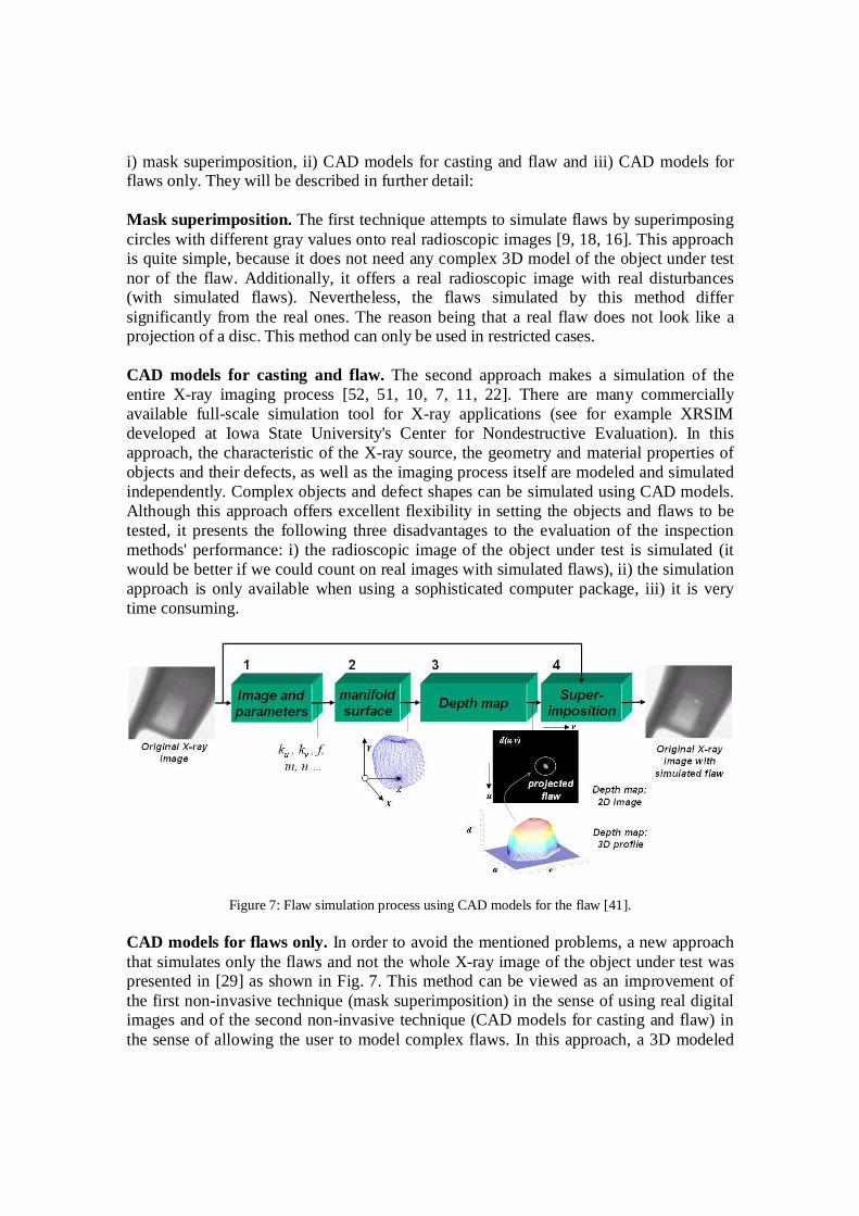
Figure 7: Flaw simulation process using CAD models for the flaw [41]. CAD models for flaws only. In order to avoid the mentioned problems, a new approach that simulates only the flaws and not the whole X-ray image of the object under test was presented in [29] as shown in Fig. 7. This method can be viewed as an improvement of the first non-invasive technique (mask superimposition) in the sense of using real digital images and of the second non-invasive technique (CAD models for casting and flaw) in the sense of allowing the user to model complex flaws. In this approach, a 3D modeled
flaw is projected and superimposed onto a real X-ray image of a homogeneous object according to the exponential attenuation law for X-rays [12]. A first approach was made in [29], where the flaws were strictly ellipsoidal, which restricts the kind of flaws that can be superimposed. Recently, a general approach using manifold surfaces was presented in [41]. This approach suits best reality not only for defects like voids or blowholes, but also cracks and any complex flaw located at any position of an aluminum casting. 5 Summary In this paper the fundamental principles of the automated detection of die casting discontinuities have been explained. A general inspection schema was presented, and several methods that have appeared in the literature in the past twenty years were explained showing the development of this sector in the areas of industry and academia. As a result of its peak detection performance, the reference inspection methods have become most widely established in industrial applications. These methods suffer from the complicated configuration of their filtering, which is tailored to the test piece. Typically, this optimization process takes two or more weeks, independently of whether it is performed manually or automatically. On the other hand, the prerequisite for the use of a method with no a priori information of the piece's structure, is the existence of common properties which define all casting discontinuities well and also differentiate them from design features of the test pieces. These prerequisites are often fulfilled only in special testing situations. Since the reported experiments do not use the same data, it is evident that an objective comparison is very difficult. Furthermore, the performance of some methods has only been tested on a limited number of cases, i.e., the reported performances are not comparable either. In addition, some methods are not reproducible because they were developed by the industry, where the know-how details may not be published. However, it is clear that the recent progress in computer technology allows the handling of various theoretical and experimental problems in science and technology which were inaccessible before. Currently, the processing of image sequences, the use of sophisticated filters in digital image processing and the simulation of discontinuities using CAD tools -to cite a few- are possible. However, in order to asses the performance objectively, it will be necessary to analyze a broader and public databank. Acknowledgment The author acknowledges the financial support from Fondecyt-Chile grant N. 1040210. References [1] K. Bavendiek. Prüfkörper für die automatischen Überprüfung der Bildqualität und der Messung der Erkennungssicherheit bei ADR Systemen. In German Conference on Nondestructive Testing, Berlin, 21-23 May 2001. (in German).
[2] H. Boerner and H. Strecker. Automated X-ray inspection of aluminum casting. IEEE Trans. Pattern Analysis and Machine Intelligence, 10(1):79-91, 1988. [3] F. Brandt. The use of X-ray inspection techniques to improve quality and reduce costs. The e-Journal of Nondestructive Testing & Ultrasonics (www.ndt.net), 5(5), May 2000. [4] J. Canny. A computational approach to edge detection. IEEE Trans. Pattern Analysis and Machine Intelligence, PAMI-8(6):679-698, 1986. [5] K. Carvajal, M. Chacón, D. Mery, and G. Acuña. Neural network method for failure detection with skewed class distribution. Insight, 46(7):399-402, 2004. [6] K.R. Castleman. Digital image processing. Prentice-Hall, Englewood Cliffs, New Jersey, 1996. [7] P. Duvauchelle, N. Freud, V. Kaftandjian, and D. Babot. A computer code to simulate X-ray imaging techniques. Nuclear Instruments and Methods in Physics Research B, 2000(170):245-258, 2000. [8] O. Faugeras, Q.-T. Luong, and T. Papadopoulo. The geometry of multiple images: The laws that govern the formation of multiple images of a scene and some of their applications. The MIT Press, Cambridge MA, London, 2001. [9] D. Filbert, R. Klatte, W. Heinrich, and M. Purschke. Computer aided inspection of castings. In IEEE-IAS Annual Meeting, pages 1087-1095, Atlanta, USA, 1987. [10] N. Freud, P. Duvauchelle, and D. Babot. Simulation of X-ray NDT imaging techniques. In Proceedings of the 15th World Conference on Non-Destructive Testing (WCNDT-2000), Rome, Oct. 15-21 2000. [11] N. Freud, P. Duvauchelle, and D. Babot. New developments in virtual X-ray imaging: Fast simulation using a deterministic approach. In AIP Conference Proceedings, volume 657(1), pages 553-560, 27 March 2003. [12] H. Haken and H.C.Wolf. The Physics of Atoms and Quanta: Introduction to Experiments and Theory. Springer, Berlin, Heidelberg, 5 edition, 1996. [13] R. Halmshaw. Non-Destructive-Testing. Edward Arnold, London, 2 edition, 1991. [14] R. Hanke, A. Kugel, and P. Troup. Automated high speed volume computed tomography for inline quality control. In Proceedings of the 16th World Conference on Non-Destructive Testing (WCNDT-2004), Montreal, Aug. 30 Sep 3 2004. [15] R. I. Hartley and A. Zisserman. Multiple view geometry in computer vision. Cambridge University Press, 2000.
[16] H. Hecker. A new method to process X-ray images in the automated inspection of castings. PhD thesis, Institute for Measurement and Automation, Faculty of Electrical Engineering, Technical University of Berlin, 1995. (in German). [17] H. Hecker. PXV 5000.2: Full automatic radioscopic test system. User manual, Philips Industrial X-ray GmbH, Hamburg, 1996. (in German). [18] W. Heinrich. Automated inspection of castings using X-ray testing. PhD thesis, Institute for Measurement and Automation, Faculty of Electrical Engineering, Technical University of Berlin, 1988. (in German). [19] S. Hernández, D. Sáez, and D. Mery. Neuro-fuzzy method for automated defect detection of aluminium castings. Lecture Notes in Computer Science, 3212:826-833, 2004. [20] F. Herold, K. Bavendiek, and R. Grigat. A new analysis and classification method for automatic defect recognition in X-ray images of castings. In 8th European Conference on Non-Destructive Testing (ECNDT 2002), Barcelona, 17-21 June 2002. [21] F. Herold, K. Bavendiek, and R. Grigat. A third generation automatic defect recognition system. In Proceedings of the 16th World Conference on Non-Destructive Testing (WCNDT-2004), Montreal, Aug. 30 Sep 3 2004. [22] F. Inanc and J.N. Gray. Scattering simulations in radiography. Applied Radiation and Isotopes, 48(10-12):1299-1305, 1997. [23] A. Kehoe and G.A. Parker. An intelligent knowledge based approach for the automated radiographic inspection of castings. NDT & E International, 25(1):23-36, 1992. [24] R. Klatte. Computer aided X-ray testing for objective quality control of workpieces. PhD thesis, Institute for Measurement and Automation, Faculty of Electrical Engineering, Technical University of Berlin, 1985. (in German). [25] J.-M. Kosanetzky. Optimization of production process in the die casting industry using full automatic radioscopic system. In Proceedings of Annual Conference of German Society of Non-Destructive Testing, volume 59.2, Dresden, 1997. (in German). [26] J.-M. Kosanetzky and H. Putzbach. Modern X-ray inspection in the automotive industry. In Proceedings of the 14th World Conference on Non-Destructive Testing (WCNDT- 1996), New Delhi, Dec. 8-13 1996. [27] S.W. Lawson and G.A. Parker. Intelligent segmentation of industrial radiographic images using neural networks. In Machine Vision Applications and Systems Integration III, Proc. of SPIE, volume 2347, pages 245-255, November 1994.
[28] D. Mery. Flaw simulation in castings inspection by radioscopy. Insight, 43(10):664-668, 2001. [29] D. Mery. A new algorithm for flaw simulation in castings by superimposing projections of 3D models onto X-ray images. In Proceedings of the XXI International Conference of the Chilean Computer Science Society (SCCC-2001), pages 193-202, Punta Arenas, 6-8 Nov. 2001. IEEE Computer Society Press. [30] D. Mery. New approaches for defect recognition with X-ray testing. Insight, 44(10):614- 615, 2002. [31] D. Mery. Crossing line profile: a new approach to detecting defects in aluminium castings. Lecture Notes in Computer Science, 2749:725-732, 2003. [32] D. Mery. Explicit geometric model of a radioscopic imaging system. NDT & E International, 36(8):587-599, 2003. [33] D. Mery. Exploiting multiple view geometry in X-ray testing: Part I, theory. Materials Evaluation, 61(11):1226-1233, November 2003. [34] D. Mery. Exploiting multiple view geometry in X-ray testing: Part II, applications. Materials Evaluation, 61(12):1311-1314, December 2003. [35] D. Mery and M. Carrasco. Automated multiple view inspection based on uncalibrated image sequences. Lecture Notes in Computer Science, 3540:1238-1247, 2005. [36] D. Mery, M. Chacón, L. Muñoz, and L. González. Automated inspection of aluminium castings using fusion strategies. Materials Evaluation, 63(2):148-153, 2005. [37] D. Mery, R. da Silva, L.P. Caloba, and J.M.A. Rebello. Pattern recognition in the automatic inspection of aluminium castings. Insight, 45(7):475-483, 2003. [38] D. Mery and D. Filbert. Automated flaw detection in aluminum castings based on the tracking of potential defects in a radioscopic image sequence. IEEE Trans. Robotics and Automation, 18(6):890-901, December 2002. [39] D. Mery and D. Filbert. Automated inspection of moving aluminium castings. The e-Journal of Nondestructive Testing & Ultrasonics (www.ndt.net), 7(12), 2002. [40] D. Mery, D. Filbert, and N. Parspour. Improvement in automated aluminum casting inspection by finding correspondence of potential flaws in multiple radioscopic images. In Proceedings of the 15th World Conference on Non-Destructive Testing (WCNDT-2000), Rome, Oct. 15-21 2000.
[41] D. Mery, D. Hahn, and N. Hitschfeld. Simulation of defects in aluminum castings using cad models of flaws and real x-ray images. Insight, 2005. (in Press). [42] D. Mery, Th. Jaeger, and D. Filbert. Fully automated X-ray inspection: Non-destructive testing in industrial applications. Materialprüufung (Material Testing), 43(11-12):433-441, 2001. (in German). [43] D. Mery, Th. Jaeger, and D. Filbert. A review of methods for automated recognition of casting defects. Insight, 44(7):428-436, 2002. [44] D. Mery, F. Ochoa, and R. Vidal. Tracking of points in a calibrated and noisy image sequence. Lecture Notes in Computer Science, 3211:647-654, 2004. [45] M. Purschke. IQI-sensitivity and applications of flat panel detectors and X-ray image intensifiers - a comparison. Insight, 44(10):628-630, 2002. [46] M. Purschke and H. Schulenburg. New possibilities in objective X-ray testing. In Proceedings of Annual Conference of German Society of Non-Destructive Testing, pages 145-151, Timmendorfer Strand, 9-11 Mai 1994. (in German). [47] M. Schaefer and M. Purschke. Full automated X-ray system: reliable and economic. QualitÄat und ZuverlÄassigkeit, 36(7), 1991. (in German). [48] H. Schulenburg and M. Purschke. Advances in the automatic evaluation of radioscopic images. In Proceedings of Anglo-German Conference on NDT Imaging and Signal Processing, Oxford, 27-28 March 1998. [49] D. Steiner and K. Bavendiek. New design of a cost effective ADR X-ray solution. In 8th European Conference on Non-Destructive Testing (ECNDT 2002), Barcelona, 17-21 June 2002. [50] G. Theis and T. Kahrs. Fully automatic X-ray inspection of aluminium wheels. In 8th European Conference on Non-Destructive Testing (ECNDT 2002), Barcelona, 17-21 June 2002. [51] G.-R. Tillack. Sophisticated X-ray imaging modalities. Insight, 44(3):158-165, 2002. [52] G.-R. Tillack, C. Nockemann, and C. Bellon. X-ray modelling for industrial applications. NDT & E International, 33(1):481-488, 2000. [53] A.G. Vincent, V. Rebuffel, R. Guillemaud, L. Gerfault, and P Y Coulon. Defect detection in industrial casting components using digital X-ray radiography. Insight, 44(10):623-627, 2004.

[54] A. Wallin and O. Kübler. Complete sets of complex Zernike moment invariants and the role of the pseudoinvariants. IEEE Trans. Pattern Analysis and Machine Intelligence, 17(11):1106-1110, 1995. [55] I. Weiske, D. Mery, C. Geisert, and D. Filbert. Implementation of a method for flaw detection in aluminium castings. The e-Journal of Nondestructive Testing & Ultrasonics (www.ndt.net), 7(3), 2002. [56] T. Wenzel and R. Hanke. Fast image processing on die castings. In Anglo-German Conference on NDT Imaging and Signal Processing, Oxford, 27-28 March 1998. Has been published in Materials Evaluation, 65(6): 643-647. ISSN 0025-5327