Embed Size (px)
Citation preview
Are the Mechanical Properties of High Pressure Die-Castings Directional?
Roger Lumley 1,2
1. Professor & Head, Department of Engineering
La Trobe University, Melbourne, Victoria 3086 , Australia
2. Technical Advisor, AWBell Pty Ltd, 145 Abbotts Road Dandenong South 3175 Victoria
ABSTRACT
A program of work examined the tensile and fracture properties of a thin wall high pressure die-cast Al-Si-Cu alloy. Plate shaped castings were used to determine whether the mechanical behaviour was influenced by the direction of metal flow. The mechanical testing results suggested that the properties of pressure die-castings may be anisotropic under some conditions. This behaviour influences both the tensile ductility and fracture resistance. It is proposed that microstructural defects are largely responsible for the anisotropy, since laminar porosity, oxide films and brittle intermetallic particles may be expected to align with the direction of metal flow. This effect appears to be operative in as-cast, T4 and T6 heat treated material, and may be instructive when considering the way in which structural thin wall die cast parts are gated.
INTRODUCTION
Aluminium alloys used for high pressure die-casting are mostly those based on the alloying systems Al-Si-Cu/Mg, and account for approximately 50% of the aluminium castings produced worldwide. Recently, the heat treatment of conventional aluminium high pressure die cast (HPDC) parts has been shown to be possible without encountering problems with blistering or dimensional instability. This process uses a heat treatment procedure which involves the use of a severely truncated solution treatment stage, followed by quenching and age hardening, a process that may significantly improve the strength properties [1]. One issue, however, is the possibility that heat treating die castings to increase tensile properties may have an adverse effect on fracture toughness. Studies of the alloys A360, A380 and C380 have shown that T4 and underaged (UA) T6 tempers produce an optimal combination of fracture resistance and tear strength [2]. Furthermore, the fracture properties compare well with permanent mold and sand cast aluminium alloys, for similar levels of tensile properties. Further improvements in fracture resistance are possible by the use of HPDC alloys tailored specifically for high fracture resistance [3].
The current paper outlines one outcome of a program of work to develop new alloy compositions with high fracture resistance [3]. Observations of anisotropic fracture behaviour are presented, which are found to be, in part, dependent on the orientation of metal flow.
EXPERIMENTAL
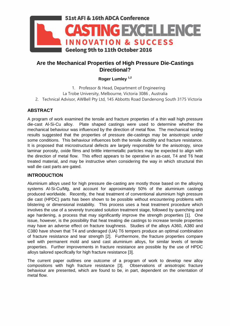
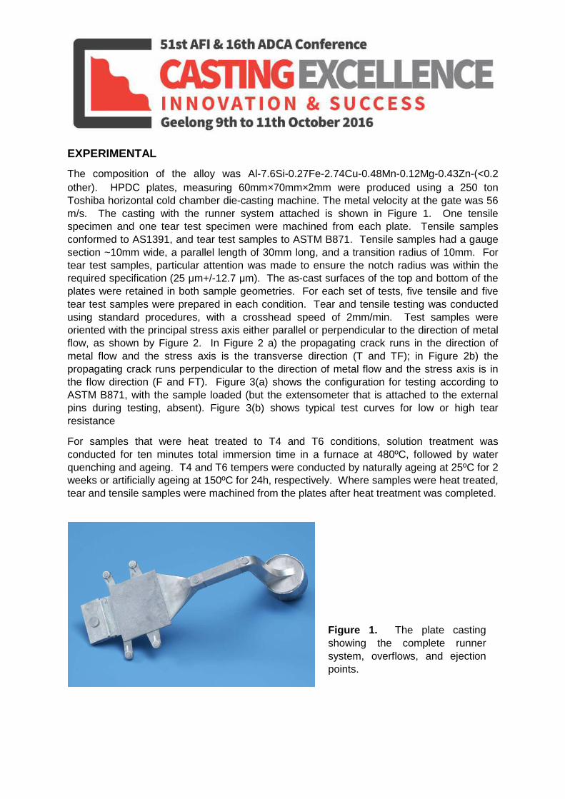
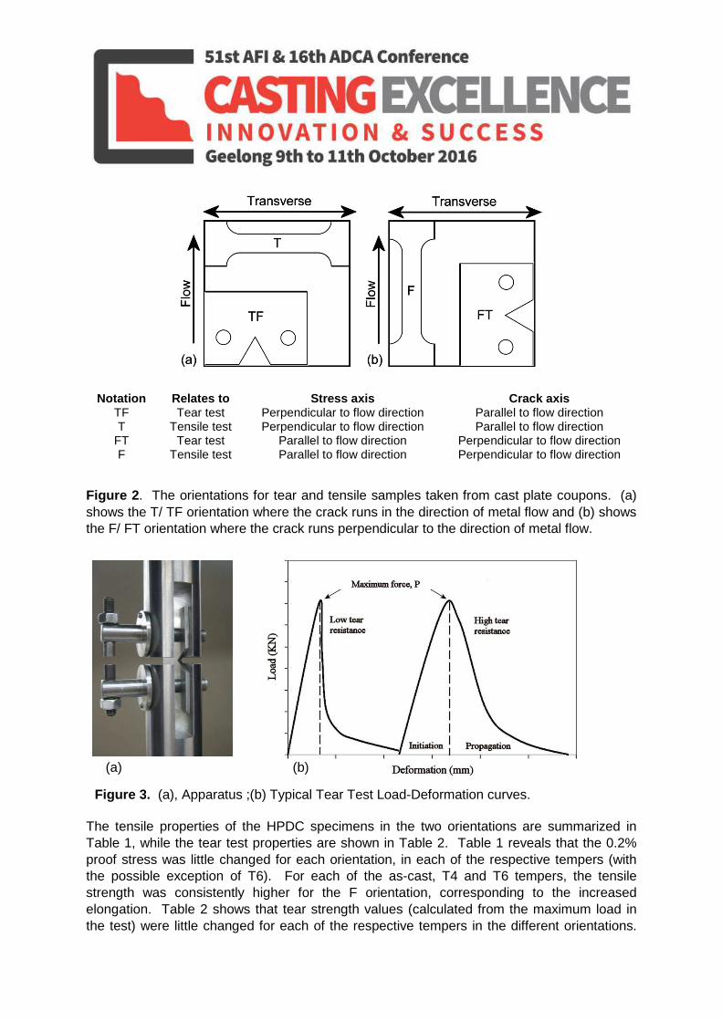
The composition of the alloy was Al-7.6Si-0.27Fe-2.74Cu-0.48Mn-0.12Mg-0.43Zn-(<0.2 other). HPDC plates, measuring 60mm×70mm×2mm were produced using a 250 ton Toshiba horizontal cold chamber die-casting machine. The metal velocity at the gate was 56 m/s. The casting with the runner system attached is shown in Figure 1. One tensile specimen and one tear test specimen were machined from each plate. Tensile samples conformed to AS1391, and tear test samples to ASTM B871. Tensile samples had a gauge section ~10mm wide, a parallel length of 30mm long, and a transition radius of 10mm. For tear test samples, particular attention was made to ensure the notch radius was within the required specification (25 μm+/-12.7 μm). The as-cast surfaces of the top and bottom of the plates were retained in both sample geometries. For each set of tests, five tensile and five tear test samples were prepared in each condition. Tear and tensile testing was conducted using standard procedures, with a crosshead speed of 2mm/min. Test samples were oriented with the principal stress axis either parallel or perpendicular to the direction of metal flow, as shown by Figure 2. In Figure 2 a) the propagating crack runs in the direction of metal flow and the stress axis is the transverse direction (T and TF); in Figure 2b) the propagating crack runs perpendicular to the direction of metal flow and the stress axis is in the flow direction (F and FT). Figure 3(a) shows the configuration for testing according to ASTM B871, with the sample loaded (but the extensometer that is attached to the external pins during testing, absent). Figure 3(b) shows typical test curves for low or high tear resistance
For samples that were heat treated to T4 and T6 conditions, solution treatment was conducted for ten minutes total immersion time in a furnace at 480ºC, followed by water quenching and ageing. T4 and T6 tempers were conducted by naturally ageing at 25ºC for 2 weeks or artificially ageing at 150ºC for 24h, respectively. Where samples were heat treated, tear and tensile samples were machined from the plates after heat treatment was completed.
Figure 1. The plate casting showing the complete runner system, overflows, and ejection points.
Notation Relates to Stress axis Crack axis TF Tear test Perpendicular to flow direction Parallel to flow direction T Tensile test Perpendicular to flow direction Parallel to flow direction
FT Tear test Parallel to flow direction Perpendicular to flow direction F Tensile test Parallel to flow direction Perpendicular to flow direction
Figure 2. The orientations for tear and tensile samples taken from cast plate coupons. (a) shows the T/ TF orientation where the crack runs in the direction of metal flow and (b) shows the F/ FT orientation where the crack runs perpendicular to the direction of metal flow.
The tensile properties of the HPDC specimens in the two orientations are summarized in Table 1, while the tear test properties are shown in Table 2. Table 1 reveals that the 0.2% proof stress was little changed for each orientation, in each of the respective tempers (with the possible exception of T6). For each of the as-cast, T4 and T6 tempers, the tensile strength was consistently higher for the F orientation, corresponding to the increased elongation. Table 2 shows that tear strength values (calculated from the maximum load in the test) were little changed for each of the respective tempers in the different orientations.
Figure 3. (a), Apparatus ;(b) Typical Tear Test Load-Deformation curves.
(a) (b)
The T6 temper again was an exception, where the sample from the FT orientation displayed higher average tear strengths of 295 MPa compared to 288 MPa for the TF orientation. The T4 temper displayed the highest tear strength of all conditions, with values of close to 340 MPa for each orientation. The notch sensitivity indices (the ratio of the tear strength to the yield strength), was also similar for each temper. Table 2 also shows the unit initiation energy, UIE (the energy absorbed up to the onset of cracking), unit propagation energy, UPE (the energy absorbed to propagate the crack), and the unit total energy, UTE for the different test conditions. What is particularly interesting is that the UIE and UPE were consistently higher on average for the FT orientation. That is, where crack propagation runs parallel to the direction of metal flow, lower overall fracture resistance is observed. As may be appreciated, the tensile properties therefore correlate to the tear test results because the elongation and tensile strength are consistently lower in the T orientations.
Table 1. Tensile properties for each of the tested conditions in each orientation
Temper and (Orientation) 0.2% Proof Stress, MPa Tensile Strength, MPa Elongation, % As Cast (T) 158 MPa 302 MPa 3.2 As Cast (F) 156 MPa 333 MPa 4.9
T4 (T) 213 MPa 357 MPa 5.1 T4 (F) 213 MPa 381 MPa 7.3 T6 (T) 331 MPa 392 MPa 2.2 T6 (F) 315 MPa 420 MPa 4.4
Table 2. Tear test properties for each of the tested conditions in each orientation.
Temper and (Orientation)
Tear Strength (MPa)
Notch Sensitivity
UIE (KJ/m2)
UPE (KJ/m2)
UTE (KJ/m2)
As Cast (TF) 242 1.55 15.9 16.9 32.8 As Cast (FT) 247 1.58 17.7 18 35.7
T4 (TF) 340 1.6 29.2 33.5 62.7 T4 (FT) 341 1.6 32.5 37.5 70 T6 (TF) 288 0.87 14.1 6.3 20.4 T6 (FT) 295 0.92 14.6 8.4 23
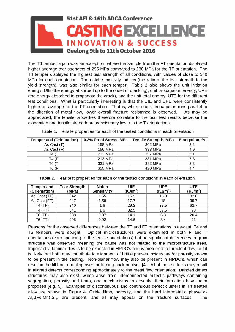
Reasons for the observed differences between the TF and FT orientations in as-cast, T4 and T6 tempers were sought. Optical microstructures were examined in both F and T orientations (corresponding to the tensile orientations) but no significant differences in grain structure was observed meaning the cause was not related to the microstructure itself. Importantly, laminar flow is to be expected in HPDC’s and is preferred to turbulent flow, but it is likely that both may contribute to alignment of brittle phases, oxides and/or porosity known to be present in the casting. Non-planar flow may also be present in HPDC’s, which can result in the fill front doubling over, or turning back on itself [4]. All of these effects may result in aligned defects corresponding approximately to the metal flow orientation. Banded defect structures may also exist, which arise from interconnected eutectic pathways containing segregation, porosity and tears, and mechanisms to describe their formation have been proposed [e.g. 5]. Examples of discontinuous and continuous defect clusters in T4 treated alloy are shown in Figure 4. Oxide films, porosity, and the hard intermetallic phase α- Al15(Fe,Mn)3Si2, are present, and all may appear on the fracture surfaces. The
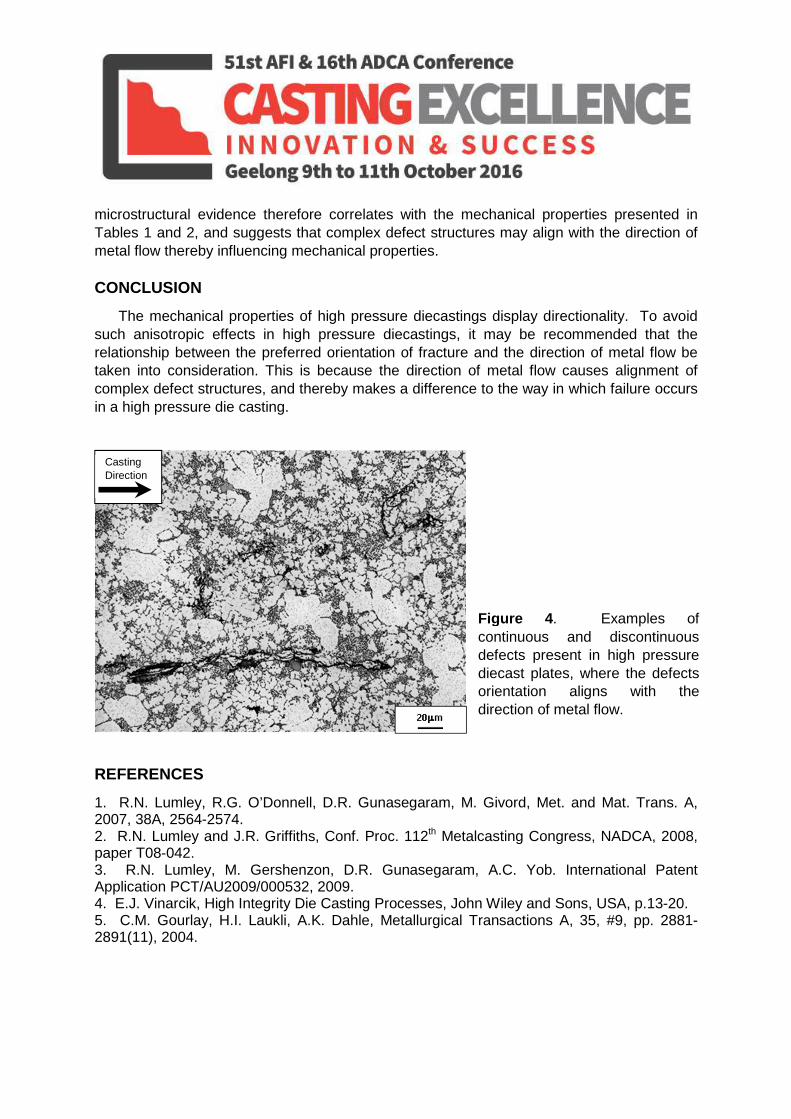
microstructural evidence therefore correlates with the mechanical properties presented in Tables 1 and 2, and suggests that complex defect structures may align with the direction of metal flow thereby influencing mechanical properties. CONCLUSION
The mechanical properties of high pressure diecastings display directionality. To avoid such anisotropic effects in high pressure diecastings, it may be recommended that the relationship between the preferred orientation of fracture and the direction of metal flow be taken into consideration. This is because the direction of metal flow causes alignment of complex defect structures, and thereby makes a difference to the way in which failure occurs in a high pressure die casting.
REFERENCES
1. R.N. Lumley, R.G. O’Donnell, D.R. Gunasegaram, M. Givord, Met. and Mat. Trans. A, 2007, 38A, 2564-2574. 2. R.N. Lumley and J.R. Griffiths, Conf. Proc. 112th Metalcasting Congress, NADCA, 2008, paper T08-042. 3. R.N. Lumley, M. Gershenzon, D.R. Gunasegaram, A.C. Yob. International Patent Application PCT/AU2009/000532, 2009. 4. E.J. Vinarcik, High Integrity Die Casting Processes, John Wiley and Sons, USA, p.13-20. 5. C.M. Gourlay, H.I. Laukli, A.K. Dahle, Metallurgical Transactions A, 35, #9, pp. 2881-2891(11), 2004.
Casting Direction
Figure 4. Examples of continuous and discontinuous defects present in high pressure diecast plates, where the defects orientation aligns with the direction of metal flow.