Embed Size (px)
DESCRIPTION
Fundamentals of CNC Machining
Citation preview
© 2011 Autodesk
5.0 - CNC Programming language

© 2011 Autodesk
Review: CNC process
• Solid Model• CAM Application
• Generate toolpaths• Verify
• Post Process• Writes G-code file
• Run G-code file on CNC machine
Solid Model
CAM(Toolpath | Verify
| Post Process)
(G-Code File) %O01111 (FACE(T2 D=0.375 )N10 G90 G94 G17N15 G20N20 G28 G91 Z0.
CNC Machine

© 2011 Autodesk
Lesson Overview
• 5.1 - CNC Language & Structure• 5.2 - CNC Editor• 5.3 - Alphabetic & Special Character Codes• 5.4 - G&M Codes• 5.5 - Select G codes in detail• 5.6 - Canned Cycles
© 2011 Autodesk
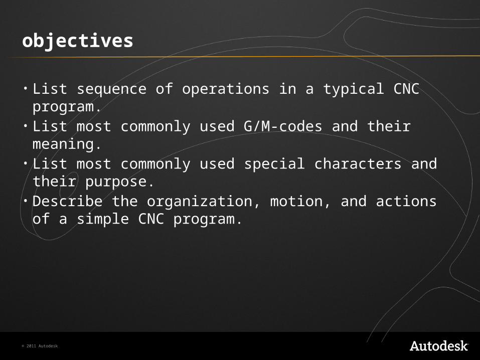
objectives
• List sequence of operations in a typical CNC program.• List most commonly used G/M-codes and their meaning.• List most commonly used special characters and their purpose.• Describe the organization, motion, and actions of a simple CNC
program.

© 2011 Autodesk
%O62806 (FACE-CONTOUR)N10 G90 G94N15 G20N20 G28 G91 Z0.N25 G90N30 M09N35 T1 M06N40 T3N45 S8149 M03N50 G54N55 M08N60 G00 X4.495 Y-3.9294N65 G43 Z0.8 H01N70 Z0.2N75 G01 Z0.0425 F20.N80 G18 G03 X4.4575 Z0.005 I-0.0375N85 G01 X-0.2575 F32.59N90 X-0.436N95 G17 G02 Y-3.7486 J0.0904N100 G01 X4.636N105 X4.6375N110 G03 Y-3.5677 J0.0904N115 G01 X-0.4375N120 G02 Y-3.3869 J0.0904N125 G01 X4.6375N130 G03 Y-3.2061 J0.0904N135 G01 X-0.4375N140 G02 Y-3.0253 J0.0904N145 G01 X4.6375
5.1 - CNC language
• CNC Machines are accurate and powerful industrial robots.
• Language: RS-274D set by Electronics Industry Association (EIA).
• Developed in 1960’s when computers had little memory.
• Slang: G-code, because many codes begin with letter “G”.

© 2011 Autodesk
Cnc language
• Very efficient and compact language.• Standardized…sort of.
• Not strictly enforced.• Many variations due to different manufacturers and machine options.
• Most common dialect: “Fanuc®” • Rhymes with “Panic”• A Japanese company.
• About 100 “words”.• About 30 used often.

© 2011 Autodesk
CNC Language
• G-code is a simple ASCII text file.• Can be read/edited in any text editor.• You DO NOT need to learn every code or how to write program by
hand.• CAM Post Processor should produce perfect code.
• CAM software should do it all, but…• It helps to know the most common codes.
• Work more efficiently.• Credibility with subordinates.

© 2011 Autodesk
CNC Program structure
• Instructions are performed in order written.• Reads like a book:
• Left -> Right• Top -> Down
• Each line (row) is called a Block.• Arranged in predictable sequence that promotes safety and
readability.
© 2011 Autodesk
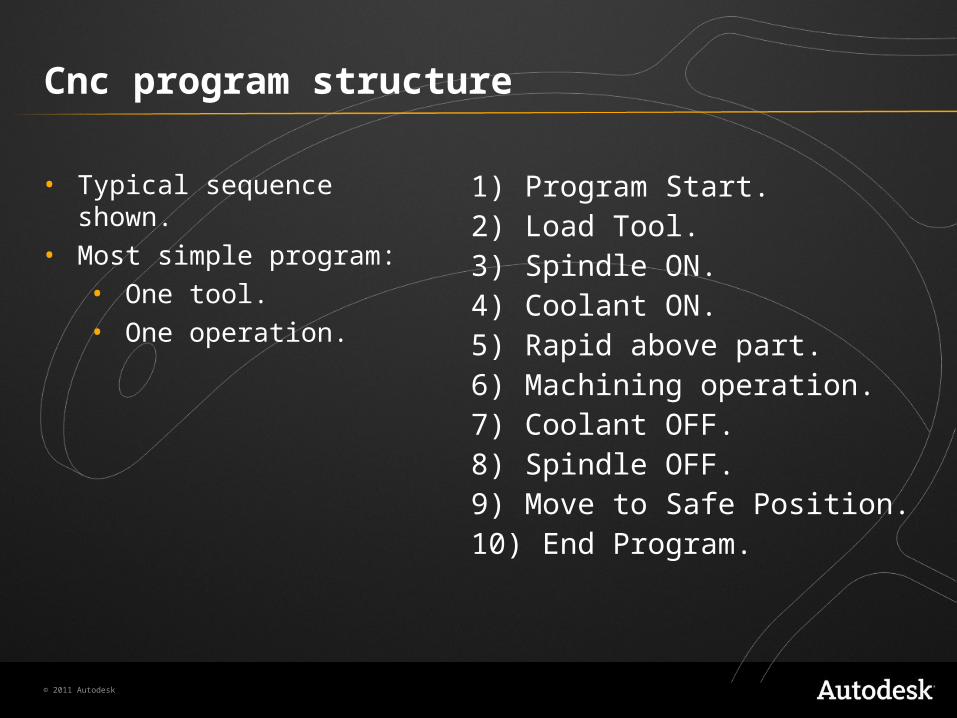
Cnc program structure
1) Program Start.2) Load Tool.3) Spindle ON.4) Coolant ON.5) Rapid above part.6) Machining operation.7) Coolant OFF.8) Spindle OFF.9) Move to Safe Position.10) End Program.
• Typical sequence shown.• Most simple program:
• One tool.• One operation.

© 2011 Autodesk
Example CNC Program
Block Description Purpose% Start of program. StartO0001 (PROJECT1) Program number (Program Name). Program(T1 0.25 END MILL) Tool description for operator.N1 G17 G20 G40 G49 G80 G90 Safety block to ensure machine is in safe mode.N2 T1 M6 Load Tool #1. ChangeN3 S9200 M3 Spindle Speed 9200 RPM, On CW. ToolN4 G54 Use Fixture Offset #1. MoveN5 M8 Coolant On. ToN6 G00 X-0.025 Y-0.275 Rapid above part. PositionN7 G43 Z1. H1 Rapid to safe plane, use Tool Length Offset #1.N8 Z0.1 Rapid to feed plane.N9 G01 Z-0.1 F18. Line move to cutting depth at 18 IPM.N10 G41 Y0.1 D1 F36. CDC Left, Lead in line, Dia. Offset #1, 36 IPM. MachineN11 Y2.025 Line move. ContourN12 X2.025 Line move.N13 Y-0.025 Line move.N14 X-0.025 Line move.N15 G40 X-0.4 Turn CDC off with lead-out move.N16 G00 Z1. Rapid to safe plane.Figure 1: Simple CNC Program

© 2011 Autodesk
Example CNC Program
Block Description PurposeN17 M5 Spindle Off. ChangeN18 M9 Coolant Off. Tool(T2 0.25 DRILL) Tool description for operator.N19 T2 M6 Load Tool #2.N20 S3820 M3 Spindle Speed 3820 RPM, On CW.N21 M8 Coolant On. MoveN22 X1. Y1. Rapid above hole. ToN23 G43 Z1. H2 Rapid to safe plane, use Tool Length Offset 2. PositionN24 Z0.25 Rapid to feed plane.N25 G98 G81 Z-0.325 R0.1 F12. Drill hole (canned) cycle, Depth Z-.325, F12. DrillN26 G80 Cancel drill cycle. HoleN27 Z1. Rapid to safe plane.N28 M5 Spindle Off. EndN29 M9 Coolant Off. ProgramN30 G91 G28 Z0N31 G91 G28 X0 Y0N32 G90
Return to machine Home position in Z.Return to machine Home position in XY.Reset to absolute positioning mode (for safety).
N33 M30 Reset program to beginning.% End Program.Figure 1: Simple CNC Program

© 2011 Autodesk
5.2 - Cnc editor
• A CNC Editor is a ASCII* text editor and CNC machine communications application.• View/Edit G-code file.• Backplot G-code file.• Transmit via RS-232 Serial communications to machine.
*ASCII (American Standard for Information Interchange) is used to represent text in computers and communications equipment.

© 2011 Autodesk
Hsmworks editor Interface

© 2011 Autodesk
5.3 Alphabetic codes/Special characters
ABCDEFGHIJKLMNOPQRSTUVWXYZ% () / ;

© 2011 Autodesk
Alphabetic codes/Special characters
• Every letter of alphabet is used.• Some used more than once.
• Meaning changes depending on G-code in same block.• Example: G02 Y-3.3869 I0.0904 J0.0904
• I, J = Arc Center data
• Example: G83 Z-.62 F15. R.05 I.15 J.01 K.005• I, J = Peck drill parameters
© 2011 Autodesk
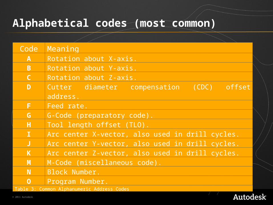
Alphabetical codes (most common)
Code MeaningA Rotation about X-axis.B Rotation about Y-axis.C Rotation about Z-axis.D Cutter diameter compensation (CDC) offset address.F Feed rate.G G-Code (preparatory code).H Tool length offset (TLO).I Arc center X-vector, also used in drill cycles.J Arc center Y-vector, also used in drill cycles.K Arc center Z-vector, also used in drill cycles.M M-Code (miscellaneous code).N Block Number.O Program Number.
Table 3: Common Alphanumeric Address Codes
© 2011 Autodesk
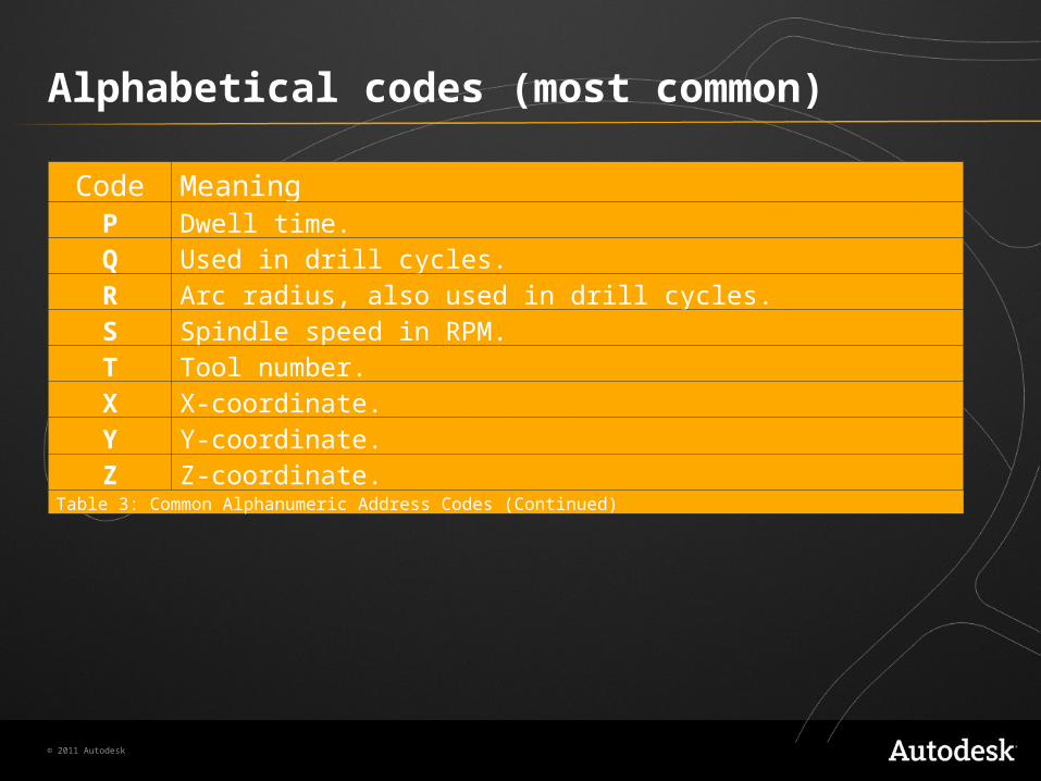
Alphabetical codes (most common)
Code MeaningP Dwell time.Q Used in drill cycles.R Arc radius, also used in drill cycles.S Spindle speed in RPM.T Tool number.X X-coordinate.Y Y-coordinate.Z Z-coordinate.
Table 3: Common Alphanumeric Address Codes (Continued)

© 2011 Autodesk
Special characters
• % Marks start and end of program.• ( ) Operator comments.• / Block Delete. This line ignored when the “Block Delete”
switch* is ON.• ; End of Block (line).
*This is a toggle switch on the CNC Control labeled, “Block Delete”.
© 2011 Autodesk
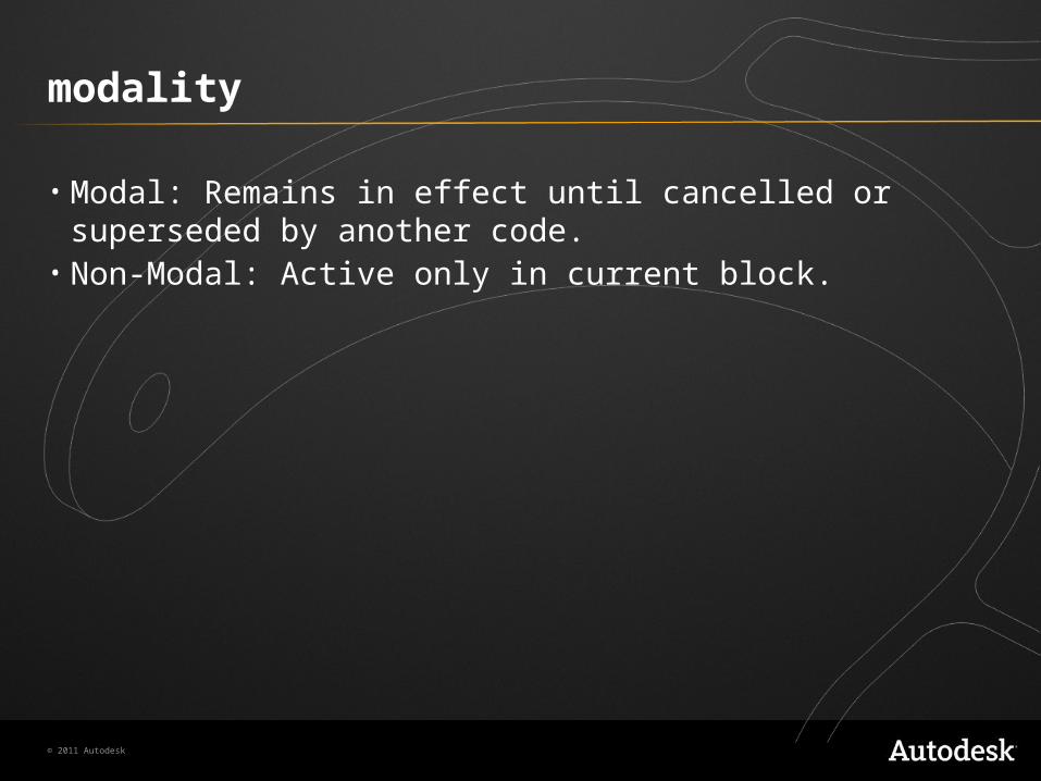
modality
• Modal: Remains in effect until cancelled or superseded by another code.
• Non-Modal: Active only in current block.

© 2011 Autodesk
5.4 - G & M codes
G1 G2 G3 G4 G28 G40 G41 G42 G43 G54 G55 G56 G57 G58 G59 G80 G81 G82 G83 G84 G90 G91 G98 G99
M0 M1 M2 M3 M4 M5 M6 M8 M9 M30

© 2011 Autodesk
G&M codes
• G-code syntax• Overview of common g-codes
• Only the ones you should know.• M-codes
• Purpose of M-codes.• M-codes you should know.

© 2011 Autodesk
G-Codes
• Begin with letter G.• Called “Preparatory codes” because they prepare machine for
certain type of motion.• Followed by 1 or 2 digit number.• Older machines required leading zeros:
• Example: G01• Newer machines do not:
• Example: G1

© 2011 Autodesk
G-Codes (Most common)
Code MeaningG0 Rapid motion. Positions machine for non-milling moves.G1 Line motion at a specified feed rate.G2 Clockwise arc.G3 Counterclockwise arc.G4 Dwell.G28 Return to machine home position.G40 Cutter Diameter Compensation (CDC) off.G41 Cutter Diameter Compensation (CDC) left.G42 Cutter Diameter Compensation (CDC) right.G43 Tool length offset (TLO).G54 Fixture Offset #1.G55 Fixture Offset #2.G56 Fixture Offset #3.
Table 1: Common G-Codes and their meaning.
© 2011 Autodesk
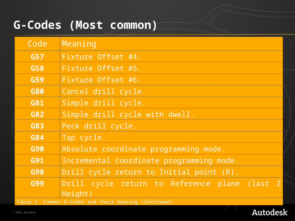
G-Codes (Most common)
Code Meaning
G57 Fixture Offset #4.
G58 Fixture Offset #5.
G59 Fixture Offset #6.
G80 Cancel drill cycle.
G81 Simple drill cycle.
G82 Simple drill cycle with dwell.
G83 Peck drill cycle.
G84 Tap cycle.
G90 Absolute coordinate programming mode.
G91 Incremental coordinate programming mode.
G98 Drill cycle return to Initial point (R).
G99 Drill cycle return to Reference plane (last Z Height)Table 1: Common G-Codes and their meaning (Continued)

© 2011 Autodesk
M-Codes
• Begin with the letter M.• Called “Miscellaneous codes” because they control machine
auxiliary options:• Coolant.• Spindle direction.
• Followed by 1 or 2 digit number.• Only one M-code per block of code.

© 2011 Autodesk
M-codes (most common)
Code Meaning
M0 Program stop. Press Cycle Start button to continue.
M1Optional stop. Only executed if Op Stop switch on the CNC control is turned ON.
M2 End of program.
M3 Spindle on Clockwise.
M4 Spindle on Counterclockwise.
M5 Spindle stop.
M6 Change tool.
M8 Coolant on.
M9 Coolant off.M30 End program and press Cycle Start to run it again.
Table 2: Common M-Codes

© 2011 Autodesk
5.5 - Select G-codes (in detail)
G0 G1 G2 G3 MotionG17 G18 G19 PlanesG43 G40 G41 G42 Tool OffsetsG54-G59 Fixture Offsets

© 2011 Autodesk
G-codes (g0 - rapid)
• Commands machine to move as fast as possible.• Caution: G0 does not move in a straight line.
• Each axis driven at max rate independently.• Result: “Dogleg” move.

© 2011 Autodesk
G-codes (g1 - linear)
• Moves machine in a straight line at a programmed feed rate.• Example: G1 X1. Y1.1255 F32.
• Read: “Move in straight line from current position to X1. Y1.1255 at a feed rate of 32 inches per minute.”

© 2011 Autodesk
G-codes (g2/g3)
• G2 = Clockwise arc.• G3 = Counterclockwise arc.• Arcs must line in a major plane (XY, XZ, YZ).• I,J are incremental distance are incremental distance arc start to
center.
© 2011 Autodesk
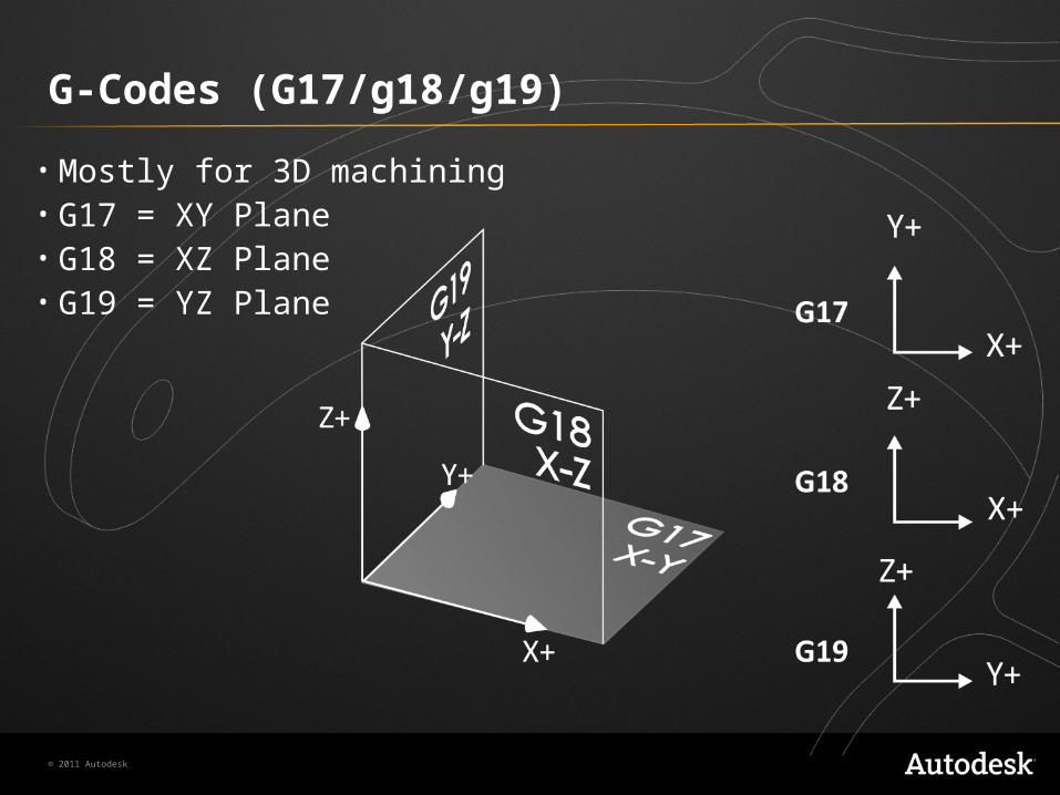
G-Codes (G17/g18/g19)
• Mostly for 3D machining• G17 = XY Plane• G18 = XZ Plane• G19 = YZ Plane

© 2011 Autodesk
G-codes (G40/G41/G42)
• Cutter diameter compensation.• A “fudge factor” used to compensate for tool wear and deflection.• A key to high precision machining!• Highly restrictive in its use (see Lesson 6: 2D Toolpaths).• G40 = OFF• G41 = LEFT• G42 = RIGHT
© 2011 Autodesk
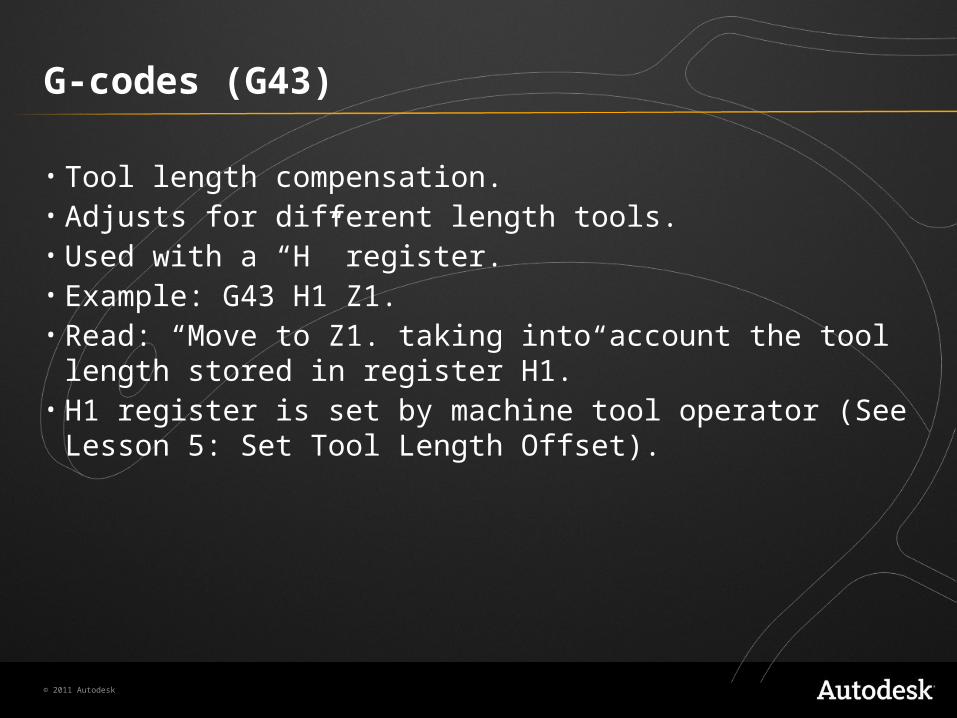
G-codes (G43)
• Tool length compensation.• Adjusts for different length tools.• Used with a “H” register.• Example: G43 H1 Z1.• Read: “Move to Z1. taking into account the tool length stored in
register H1.”• H1 register is set by machine tool operator (See Lesson 5: Set
Tool Length Offset).

© 2011 Autodesk
G-codes (g54 – G59)
• Work Coordinate Offset (WCS).• Call a machine WCS register.• XY shifts CNC from Machine Coordinates to CNC program
coordinates.• Z along with TLO shifts CNC from Machine Coordinates to CNC
program coordinates, taking into account each tool’s unique length (how far it extends from machine spindle face).
© 2011 Autodesk
5.6 - Canned cycles
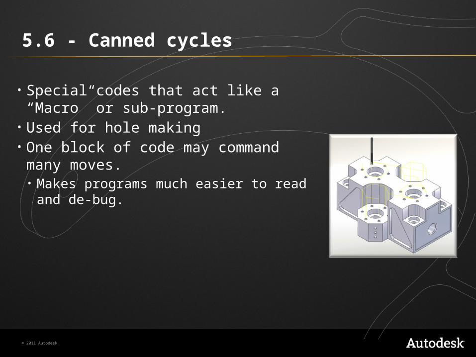
• Special codes that act like a “Macro” or sub-program.
• Used for hole making• One block of code may command many
moves.• Makes programs much easier to read and de-
bug.

© 2011 Autodesk
Canned cycle vs. expanded code
N70 G98 G83 X1. Y1. Z-1.04 R0.06 Q0.15 P0 F9.N75 G80
N70 Z0.06N75 Z0.04N80 G01 Z-0.19 F9.N85 G00 Z0.06N90 Z-0.11N95 G01 Z-0.34N100 G00 Z0.06N105 Z-0.26N110 G01 Z-0.49.N115 G00 Z0.06N120 Z-0.41N125 G01 Z-0.64.N130 G00 Z0.06N135 Z-0.56N140 G01 Z-0.79N145 G00 Z0.06N150 Z-0.71N155 G01 Z-0.94.N160 G00 Z0.06N165 Z-0.86N170 G01 Z-1.04.N175 G00 Z0.25
Canned Cycle Equivalent Motion: Expanded Code

© 2011 Autodesk
G-codes (G81)
• Simple drill cycle.• Drill in/Rapid out.• Example: G98 G81 X.5 Y.5 Z-1. R.1 F9.5• R is rapid plane (sets retract Z).• G98/G99 controls how much tool retracts between holes.• Read: “Go to X.5, Y.5, Z.1 (set by R.1) and drill to depth Z-1. at a
feed rate of 9.5 in/min.”

© 2011 Autodesk
G-codes (g82)
• Spot drill cycle.• Same as drill cycle but with dwell to produce a clean face, set by
P-value.• Example: G98 G82 X.5 Y.5 Z-.0925 P.1 R.1 F9.5• P.1 = .1 second dwell after reaching Z-.0925 then rapid retract.
© 2011 Autodesk
G-codes (G84)
• Tapping cycle.• Feed rate is determined by spindle speed and thread lead.• Many machines have rigid tapping.
• Can tap on machine without special attachments.• Spindle rotation precisely controlled by servo.• Will reverse at hole bottom and back out again.

© 2011 Autodesk
G-codes (g90)
• Absolute positioning mode.• All CAM-generated programs positions should be in Absolute
mode.
© 2011 Autodesk
G-codes (G91)
• Incremental positioning.• Only has one purpose with CAM-generated programs: fully
retract spindle in XY or Z.• Example:
G91 G28 Z0. (RETRACT IN Z)G90 (RESET TO ABSOLUTE)
© 2011 Autodesk
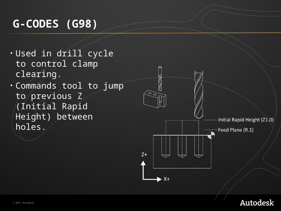
G-CODES (G98)
• Used in drill cycle to control clamp clearing.
• Commands tool to jump to previous Z (Initial Rapid Height) between holes.
© 2011 Autodesk
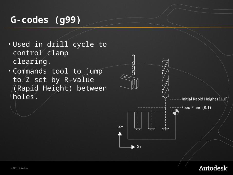
G-codes (g99)
• Used in drill cycle to control clamp clearing.
• Commands tool to jump to Z set by R-value (Rapid Height) between holes.

© 2011 Autodesk
summary
• CNC Program is called a “G-code” file.• A simple ASCII character file.• Can be read in any text editor.• Fanuc is common standard.• Programs should follow a predictable specific sequence of events.• G-codes = Preparatory commands.• M-codes = Miscellaneous commands.

© 2011 Autodesk
summary
• Alphabetic address codes: • Can have different meanings depending on which G-code
accompanied by.• Special characters (see list).• Canned Cycles (G80-G84) work like a macro.• G0 is rapid (not necessarily a straight line).• G1 is straight line move at programmed feed rate.
© 2011 Autodesk
summary
• G2 is Clockwise arc.• G3 is Counterclockwise arc.• CAM software should output absolutely edit-free code.
• If not -contact the manufacturer.• You should know the most commonly used codes so you can
work efficiently.