Embed Size (px)
Citation preview
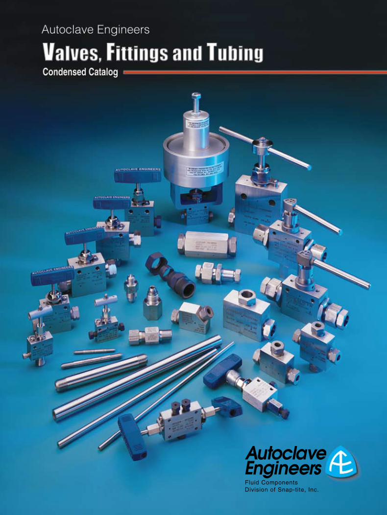
Autoclave Engineers
2
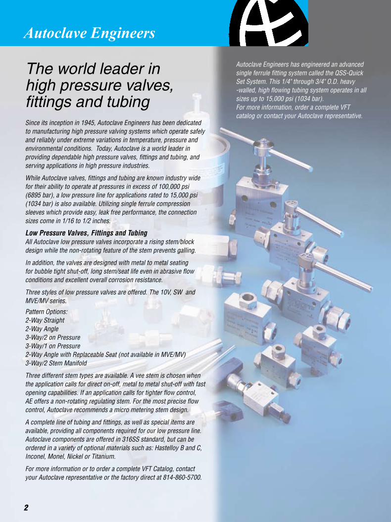
The world leader in high pressure valves, fittings and tubingSince its inception in 1945, Autoclave Engineers has been dedicated to manufacturing high pressure valving systems which operate safely and reliably under extreme variations in temperature, pressure and environmental conditions. Today, Autoclave is a world leader in providing dependable high pressure valves, fittings and tubing, and serving applications in high pressure industries.
While Autoclave valves, fittings and tubing are known industry wide for their ability to operate at pressures in excess of 100,000 psi (6895 bar), a low pressure line for applications rated to 15,000 psi (1034 bar) is also available. Utilizing single ferrule compression sleeves which provide easy, leak free performance, the connection sizes come in 1/16 to 1/2 inches.
Low Pressure Valves, Fittings and TubingAll Autoclave low pressure valves incorporate a rising stem/block design while the non-rotating feature of the stem prevents galling.
In addition, the valves are designed with metal to metal seating for bubble tight shut-off, long stem/seat life even in abrasive flow conditions and excellent overall corrosion resistance.
Three styles of low pressure valves are offered. The 10V, SW and MVE/MV series.
Pattern Options:2-Way Straight2-Way Angle3-Way/2 on Pressure3-Way/1 on Pressure2-Way Angle with Replaceable Seat (not available in MVE/MV)3-Way/2 Stem Manifold
Three different stem types are available. A vee stem is chosen when the application calls for direct on-off, metal to metal shut-off with fast opening capabilities. If an application calls for tighter flow control, AE offers a non-rotating regulating stem. For the most precise flow control, Autoclave recommends a micro metering stem design.
A complete line of tubing and fittings, as well as special items are available, providing all components required for our low pressure line. Autoclave components are offered in 316SS standard, but can be ordered in a variety of optional materials such as: Hastelloy B and C, Inconel, Monel, Nickel or Titanium.
For more information or to order a complete VFT Catalog, contact your Autoclave representative or the factory direct at 814-860-5700.
Autoclave Engineers has engineered an advanced single ferrule fitting system called the QSS-Quick Set System. This 1/4" through 3/4" O.D. heavy -walled, high flowing tubing system operates in all sizes up to 15,000 psi (1034 bar). For more information, order a complete VFT catalog or contact your Autoclave representative.
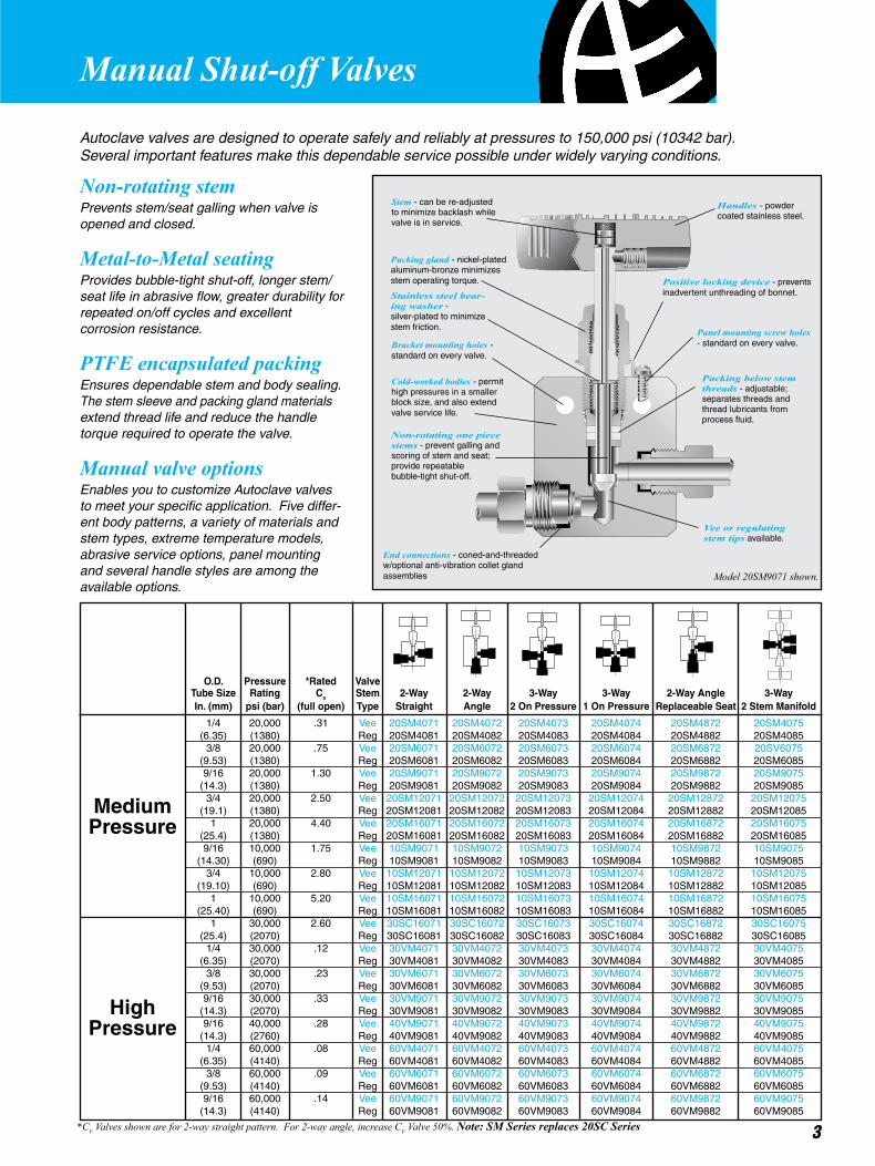
Autoclave valves are designed to operate safely and reliably at pressures to 150,000 psi (10342 bar). Several important features make this dependable service possible under widely varying conditions.
Manual Shut-off Valves
Non-rotating stemPrevents stem/seat galling when valve is opened and closed.
Metal-to-Metal seatingProvides bubble-tight shut-off, longer stem/seat life in abrasive flow, greater durability for repeated on/off cycles and excellent corrosion resistance.
PTFE encapsulated packingEnsures dependable stem and body sealing. The stem sleeve and packing gland materials extend thread life and reduce the handle torque required to operate the valve.
Manual valve optionsEnables you to customize Autoclave valves to meet your specific application. Five differ-ent body patterns, a variety of materials and stem types, extreme temperature models, abrasive service options, panel mounting and several handle styles are among the available options.
O.D. Pressure *Rated Valve Tube Size Rating Cv Stem 2-Way 2-Way 3-Way 3-Way 2-Way Angle 3-Way In. (mm) psi (bar) (full open) Type Straight Angle 2 On Pressure 1 On Pressure Replaceable Seat 2 Stem Manifold
1/4 20,000 .31 Vee 20SM4071 20SM4072 20SM4073 20SM4074 20SM4872 20SM4075 (6.35) (1380) Reg 20SM4081 20SM4082 20SM4083 20SM4084 20SM4882 20SM4085 3/8 20,000 .75 Vee 20SM6071 20SM6072 20SM6073 20SM6074 20SM6872 20SV6075 (9.53) (1380) Reg 20SM6081 20SM6082 20SM6083 20SM6084 20SM6882 20SM6085 9/16 20,000 1.30 Vee 20SM9071 20SM9072 20SM9073 20SM9074 20SM9872 20SM9075 (14.3) (1380) Reg 20SM9081 20SM9082 20SM9083 20SM9084 20SM9882 20SM9085 3/4 20,000 2.50 Vee 20SM12071 20SM12072 20SM12073 20SM12074 20SM12872 20SM12075 (19.1) (1380) Reg 20SM12081 20SM12082 20SM12083 20SM12084 20SM12882 20SM12085 1 20,000 4.40 Vee 20SM16071 20SM16072 20SM16073 20SM16074 20SM16872 20SM16075 (25.4) (1380) Reg 20SM16081 20SM16082 20SM16083 20SM16084 20SM16882 20SM16085 9/16 10,000 1.75 Vee 10SM9071 10SM9072 10SM9073 10SM9074 10SM9872 10SM9075 (14.30) (690) Reg 10SM9081 10SM9082 10SM9083 10SM9084 10SM9882 10SM9085 3/4 10,000 2.80 Vee 10SM12071 10SM12072 10SM12073 10SM12074 10SM12872 10SM12075 (19.10) (690) Reg 10SM12081 10SM12082 10SM12083 10SM12084 10SM12882 10SM12085 1 10,000 5.20 Vee 10SM16071 10SM16072 10SM16073 10SM16074 10SM16872 10SM16075 (25.40) (690) Reg 10SM16081 10SM16082 10SM16083 10SM16084 10SM16882 10SM16085 1 30,000 2.60 Vee 30SC16071 30SC16072 30SC16073 30SC16074 30SC16872 30SC16075 (25.4) (2070) Reg 30SC16081 30SC16082 30SC16083 30SC16084 30SC16882 30SC16085 1/4 30,000 .12 Vee 30VM4071 30VM4072 30VM4073 30VM4074 30VM4872 30VM4075 (6.35) (2070) Reg 30VM4081 30VM4082 30VM4083 30VM4084 30VM4882 30VM4085 3/8 30,000 .23 Vee 30VM6071 30VM6072 30VM6073 30VM6074 30VM6872 30VM6075 (9.53) (2070) Reg 30VM6081 30VM6082 30VM6083 30VM6084 30VM6882 30VM6085 9/16 30,000 .33 Vee 30VM9071 30VM9072 30VM9073 30VM9074 30VM9872 30VM9075 (14.3) (2070) Reg 30VM9081 30VM9082 30VM9083 30VM9084 30VM9882 30VM9085 9/16 40,000 .28 Vee 40VM9071 40VM9072 40VM9073 40VM9074 40VM9872 40VM9075 (14.3) (2760) Reg 40VM9081 40VM9082 40VM9083 40VM9084 40VM9882 40VM9085 1/4 60,000 .08 Vee 60VM4071 60VM4072 60VM4073 60VM4074 60VM4872 60VM4075 (6.35) (4140) Reg 60VM4081 60VM4082 60VM4083 60VM4084 60VM4882 60VM4085 3/8 60,000 .09 Vee 60VM6071 60VM6072 60VM6073 60VM6074 60VM6872 60VM6075 (9.53) (4140) Reg 60VM6081 60VM6082 60VM6083 60VM6084 60VM6882 60VM6085 9/16 60,000 .14 Vee 60VM9071 60VM9072 60VM9073 60VM9074 60VM9872 60VM9075 (14.3) (4140) Reg 60VM9081 60VM9082 60VM9083 60VM9084 60VM9882 60VM9085
MediumPressure
HighPressure
Stem - can be re-adjusted to minimize backlash while valve is in service.
Model 20SM9071 shown.
Packing gland - nickel-plated aluminum-bronze minimizes stem operating torque.
End connections - coned-and-threaded w/optional anti-vibration collet gland assemblies
Non-rotating one piece stems - prevent galling and scoring of stem and seat; provide repeatable bubble-tight shut-off.
Cold-worked bodies - permit high pressures in a smaller block size, and also extend valve service life.
Bracket mounting holes - standard on every valve.
Panel mounting screw holes - standard on every valve.
Vee or regulating stem tips available.
Packing below stem threads - adjustable; separates threads and thread lubricants from process fluid.
Stainless steel bear-ing washer - silver-plated to minimize stem friction.
Positive locking device - prevents inadvertent unthreading of bonnet.
3*CV Valves shown are for 2-way straight pattern. For 2-way angle, increase CV Valve 50%. Note: SM Series replaces 20SC Series
Handles - powdercoated stainless steel.
4
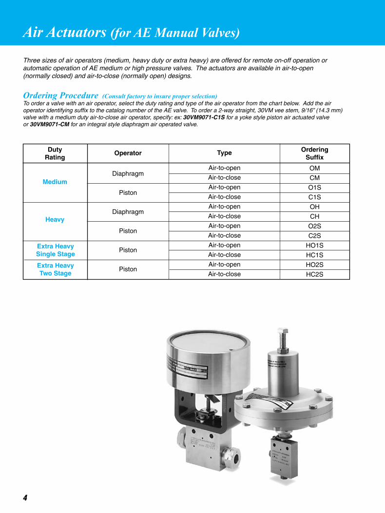
Three sizes of air operators (medium, heavy duty or extra heavy) are offered for remote on-off operation or automatic operation of AE medium or high pressure valves. The actuators are available in air-to-open (normally closed) and air-to-close (normally open) designs.
Ordering Procedure (Consult factory to insure proper selection)To order a valve with an air operator, select the duty rating and type of the air operator from the chart below. Add the air operator identifying suffix to the catalog number of the AE valve. To order a 2-way straight, 30VM vee stem, 9/16” (14.3 mm) valve with a medium duty air-to-close air operator, specify: ex: 30VM9071-C1S for a yoke style piston air actuated valve or 30VM9071-CM for an integral style diaphragm air operated valve.
DutyRating
OrderingSuffix
Operator Type
Air-to-open
Air-to-close
Air-to-open
Air-to-close
Air-to-open
Air-to-close
Air-to-open
Air-to-close
Air-to-open
Air-to-close
Air-to-open
Air-to-close
OM
CM
O1S
C1S
OH
CH
O2S
C2S
HO1S
HC1S
HO2S
HC2S
Diaphragm
Piston
Diaphragm
Piston
Piston
Piston
Medium
Heavy
Extra HeavySingle Stage
Air Actuators (for AE Manual Valves)
Extra HeavyTwo Stage

This table is designed to allow quick selection of an appropriate air actuator based on valve style and size, maximum system operating pressure and maximum available air pressure. For example, if the system operating pressure is 25,000 psi (1723 bar) and the available air pressure is 60 psi (4.1 bar) and an air-to-open (spring fail closed) valve is required, a 30VM or 60VM valve with a heavy duty air operator can be used.
ValveSeries
O.D.Tube
in. (mm)
SystemPress.
psi (bar)
AirPress.
psi (bar)
SystemPress.
psi (bar)
AirPress.
psi (bar)
SystemPress.
psi (bar)
AirPress.
psi (bar)
Medium Heavy Extra Heavy Single Stage
9/16 8,600 100 10,000 55 10,000 45 10,000 20 (14.3) (593) (6.9) (690) (3.8) (690) (3.10) (690) (1.4) 3/4 4,800 100 10,000 100 10,000 70 10,000 35 (19.1) (331) (6.9) (690) (6.9) (690) (4.83) (690) (2.4) 1 2,800 100 6,300 100 8,500 95 10,000 55 (25.4) (193) (6.9) (434) (6.9) (586) (6.55) (690) (3.79) 1/4 20,000 95 20,000 50 __ __ __ __ (6.35) (1380) (6.5) (1380) (3.5) 3/8 19,000 100 20,000 55 __ __ __ __ (9.53) (1310) (6.9) (1380) (3.8) 9/16 10,700 100 20,000 85 20,000 65 20,000 30 (14.3) (734) (6.9) (1380) (5.9) (1380) (4.48) (1380) (2.1) 3/4 6,100 100 13,600 100 19,000 100 20,000 50 (19.1) (421) (6.9) (938) (6.9) (1310) (6.90) (1380) (3.4) 1 3,900 100 8,800 100 19,000 95 20,000 75 (25.4) (269) (6.9) (607) (6.9) (1310) (6.55) (1380) (5.1) 1 __ __ __ __ __ __ 30,000 80 (25.4) (2068) (5.5) 1/4 30,000 55 30,000 30 __ __ __ __ (6.35) (2068) (3.8) (2068) (2.0) 3/8 30,000 75 30,000 40 __ __ __ __ (9.53) (2068) (5.2) (2068) (2.8) 9/16 30,000 75 30,000 40 __ __ __ __ (14.3) (2068) (5.2) (2068) (2.8) 9/16 __ __ 40,000 45 __ __ __ __ (14.3) (2758) (3.1) 1/4 60,000 75 60,000 40 __ __ __ __ (6.35) (4137) (5.2) (4137) (2.8) 3/8 60,000 75 60,000 40 __ __ __ __ (9.53) (4137) (5.2) (4137) (2.8) 9/16 60,000 90 60,000 45 __ __ __ __ (14.3) (4137) (6.2) (4137) (3.1)
1/4 20,000 95 20,000 50 __ __ __ __ (6.35) (1380) (6.6) (1380) (3.4) 3/8 18,250 95 18,250 50 __ __ __ __ (9.53) (1258) (6.6) (1258) (3.4) 9/16 9,800 95 15,700 75 20,000 85 20,000 55 (14.3) (676) (6.6) (1082) (5.1) (1379) (5.86) (1380) (3.8) 3/4 __ __ 6,000 75 15,000 100 20,000 80 (19.1) (414) (5.1) (1034) (6.90) (1380) (5.5) 1 __ __ 4,000 75 10,000 100 20,000 100 (25.4) (276) (5.1) (690) (6.90) (1380) (6.9) 1 __ __ __ __ __ __ 30,000 100 (25.4) (2068) (6.9) 1/4 30,000 75 30,000 40 __ __ __ __ (6.35) (2068) (5.2) (2068) (2.8) 3/8 30,000 95 30,000 50 __ __ __ __ (9.53) (2068) (6.5) (2068) (3.5) 9/16 30,000 95 30,000 50 __ __ __ __ (14.3) (2068) (6.5) (2068) (3.5) 9/16 __ __ 40,000 55 __ __ __ __ (14.3) (2758) (3.8) 1/4 60,000 95 60,000 50 __ __ __ __ (6.35) (4137) (6.5) (4137) (3.5) 3/8 60,000 95 60,000 50 __ __ __ __ (9.53) (4137) (6.5) (4137) (3.5) 9/16 60,000 95 60,000 50 __ __ __ __ (14.3) (4137) (6.5) (4137) (3.5)
5
Air-to-open
Air-to-close
10SM
30SC
30VM
40VM
60VM
20SM
30SC
30VM
40VM
60VM
20SM
9/16 7,900 95 10,000 75 10,000 60 10,000 40 (14.3) (545) (6.6) (690) (5.1) (690) (4.13) (690) (2.8) 3/4 __ __ __ __ 10,000 95 10,000 60 (9.1) (690) (6.55) (690) (4.1) 1 __ __ __ __ 6,500 100 10,000 85 (25.4) (448) (6.90) (690) (5.9)
10SM
Extra Heavy Two StageSystemPress.
psi (bar)
AirPress.
psi (bar)
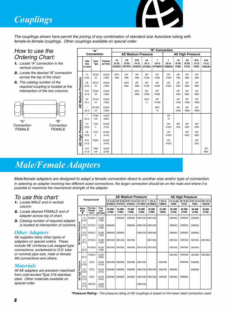
Couplings
6
The couplings shown here permit the joining of any combination of standard size Autoclave tubing with female-to-female couplings. Other couplings available on special order.
Male/Female AdaptersMale/female adapters are designed to adapt a female connection direct to another size and/or type of connection.In selecting an adapter involving two different sized connections, the larger connection should be on the male end where it is possible to maximize the mechanical strength of the adapter.
How to use the Ordering Chart:1. Locate “A” connection in the vertical column.
2. Locate the desired “B” connection across the top of the chart.
3. The catalog number of the required coupling is located at the intersection of the two columns.
To use this chart:1. Locate MALE end in vertical column.2. Locate desired FEMALE end of adapter across top of chart.3. Catalog number of required adapter is located at intersection of columns.
Other AdaptersAE supplies many other types of adapters on special orders. These include AE UniVersa-Lok swaged-type connections, socketweld to O.D. tube or nominal pipe size, male or female AN connections and others.
MaterialsAll AE adapters are precision machined from cold-worked Type 316 stainless steel. Other materials available on special order.
TubeSize
in.(mm)
Conn.Type
Pressurepsi*(bar)
1/4 (6.35)
SF250CX
3/8 (9.53)
SF375CX
9/16(14.3)
SF562CX
3/4(19.1)
SF750CX
1(25.4)
SF1000CX
1(25.4)
F1000C43
1/4(6.35)F250C
3/8(9.53)F375C
9/16(14.3)F562C
“A”Connection
“B” Connection
AE
Med
ium
Pre
ssu
reA
E H
igh
Pre
ssu
re
1/4 SF250 20,000 20FX 20F 20F 20F 20F 20F 20F 20F 20F (6.35) CX (1380) 4466 4666 4966 41266 41666 41663 4463 4663 4963
3/8 SF375 20,000 20FX 20F 20F 20F 20F 20F 20F 20F (9.53) CX (1380) 6666 6966 61266 61666 61663 6463 6663 6963
9/16 SF562 20,000 20FX 20F 20F 20F 20F 20F (14.3) CX (1380) 9966 91266 91666 9463 9663 9963
3/4 SF750 20,000 20FX 20F 20F 20F 20F (19.1) CX (1380) 12 121666 12463 12663 12963
1 SF1000 20,000 20FX 20F 20F 20F (25.4) CX (1380) 16 16463 16663 16963
1 F1000 43,000 43F (25.4) C43 (2964) 16
1/4 F250 60,000 43F 60F 60F 60F (6.35) C (4140) 41633 4433 4633 4933
3/8 F375 60,000 43F 60F 60F (9.53) C (4140) 61633 6633 6933
9/16 F562C 60,000 43F 60F (14.3) (4140) 91633 9333
9/16 F562 40,000 (14.3) C40 (2758)
AE Medium Pressure AE High Pressure
9/16”(14.3)F562C
Female End AE Medium Pressure AE High Pressure
AE
Med
ium
Pre
ssu
reA
E H
igh
Pre
ssu
re
MaleEnd
3/8”(9.53)F375C
1/4”(6.35)F250C
1”(25.4)F1000C43
1”(25.4)SF1000CX
3/4”(19.1)SF750CX
9/16”(14.3)SF562CX
3/8”(9.53)SF375CX
1/4”(6.35)SF250CX
Fits thisFemaleConn.
Pres-sure
psi*(bar)
1/4 (6.35)
3/8 (9.53)
9/16 (14.3)
3/4 (19.1)
1 (25.4)
1 (25.4)
1/4 (6.35)
3/8 (9.53)
9/16 (14.3)
SF250CX
SF375CX
SF562CX
SF750CX
SF1000CX
F1000C43
F250C
F375C
F562C
20M64K6
20M94K6
20M124K6
20M164K6
20M44B6
20M64B6
20M94B6
20M46K6
20M96K6
20M126K6
20M166K6
20M46B6
20M66B6
20M96B6
20M49K6
20M69K6
20M129K6
20M169K6
20M49B6
20M69B6
20M99B6
20M412K6
20M612K6
20M912K6
20M1612K6
20M412B6
20M612B6
20M912B6
20M416K6
20M616K6
20M916K6
20M1216K6
20M1616K6
20M616B6
20M916B6
43M416B6
43M616B6
43M916B6
20M44K3
20M64K3
20M94K3
20M124K3
20M164K3
43M164B3
60M64B3
60M94B3
20M46K3
20M66K3
20M96K3
20M126K3
20M166K3
43M166B3
60M46B3
60M96B3
20M49K3
20M69K3
20M99K3
20M129K3
20M169K3
43M169B3
60M49B3
60M69B3
20,000 (1380)
“A” ConnectionFEMALE
“B” ConnectionFEMALE
*Pressure Rating - The pressure rating of AE couplings is based on the lower rated connection used.
20,000 (1380)
20,000 (1380)
20,000 (1380)
20,000 (1380)
43,000 (2964)
60,000 (4140)
60,000 (4140)
60,000 (4140)
20,000 (1380)
20,000 (1380)
20,000 (1380)
20,000 (1380)
20,000 (1380)
43,000 (2964)
60,000 (4140)
60,000 (4140)
60,000 (4140)
9/16(14.3)
F562C40
40F9933
9/16”(14.3)F562C40
40,000 (2758)
20M129K40
9/16 (14.3)
F562C40 40,000 (2758)
20M912G6
43M169B40
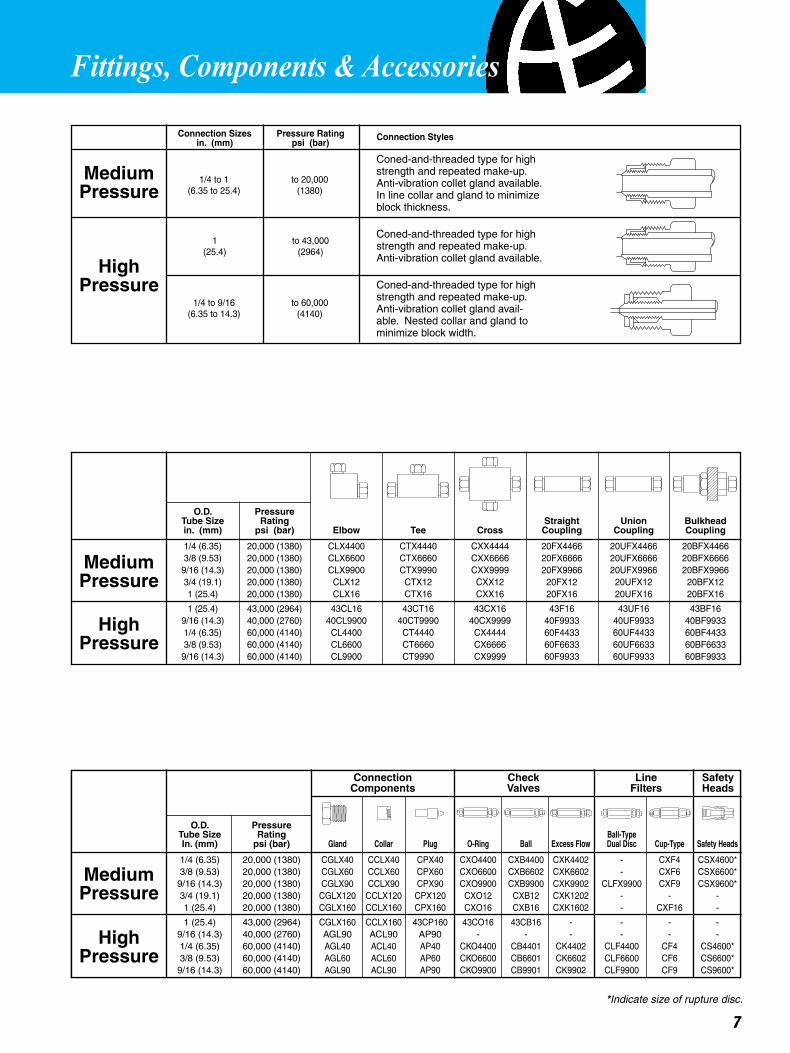
7
Coned-and-threaded type for high strength and repeated make-up. Anti-vibration collet gland available. In line collar and gland to minimize block thickness.
Coned-and-threaded type for high strength and repeated make-up. Anti-vibration collet gland available.
Coned-and-threaded type for high strength and repeated make-up. Anti-vibration collet gland avail-able. Nested collar and gland to minimize block width.
1/4 to 1 to 20,000 (6.35 to 25.4) (1380)
Connection Sizes Pressure Rating in. (mm) psi (bar)
Connection Check Line Safety Components Valves Filters Heads
O.D. Pressure Tube Size Rating Straight Union Bulkhead in. (mm) psi (bar) Elbow Tee Cross Coupling Coupling Coupling
1/4 (6.35) 20,000 (1380) CLX4400 CTX4440 CXX4444 20FX4466 20UFX4466 20BFX4466 3/8 (9.53) 20,000 (1380) CLX6600 CTX6660 CXX6666 20FX6666 20UFX6666 20BFX6666 9/16 (14.3) 20,000 (1380) CLX9900 CTX9990 CXX9999 20FX9966 20UFX9966 20BFX9966 3/4 (19.1) 20,000 (1380) CLX12 CTX12 CXX12 20FX12 20UFX12 20BFX12 1 (25.4) 20,000 (1380) CLX16 CTX16 CXX16 20FX16 20UFX16 20BFX16
1 (25.4) 43,000 (2964) 43CL16 43CT16 43CX16 43F16 43UF16 43BF16 9/16 (14.3) 40,000 (2760) 40CL9900 40CT9990 40CX9999 40F9933 40UF9933 40BF9933 1/4 (6.35) 60,000 (4140) CL4400 CT4440 CX4444 60F4433 60UF4433 60BF4433 3/8 (9.53) 60,000 (4140) CL6600 CT6660 CX6666 60F6633 60UF6633 60BF6633 9/16 (14.3) 60,000 (4140) CL9900 CT9990 CX9999 60F9933 60UF9933 60BF9933
1 to 43,000 (25.4) (2964)
1/4 to 9/16 to 60,000 (6.35 to 14.3) (4140)
Connection Styles
MediumPressure
HighPressure
MediumPressure
HighPressure
MediumPressure
HighPressure
*Indicate size of rupture disc.
Fittings, Components & Accessories
O.D. Pressure Tube Size Rating Ball-Type In. (mm) psi (bar) Gland Collar Plug O-Ring Ball Excess Flow Dual Disc Cup-Type Safety Heads
1/4 (6.35) 20,000 (1380) CGLX40 CCLX40 CPX40 CXO4400 CXB4400 CXK4402 - CXF4 CSX4600* 3/8 (9.53) 20,000 (1380) CGLX60 CCLX60 CPX60 CXO6600 CXB6602 CXK6602 - CXF6 CSX6600* 9/16 (14.3) 20,000 (1380) CGLX90 CCLX90 CPX90 CXO9900 CXB9900 CXK9902 CLFX9900 CXF9 CSX9600* 3/4 (19.1) 20,000 (1380) CGLX120 CCLX120 CPX120 CXO12 CXB12 CXK1202 - - - 1 (25.4) 20,000 (1380) CGLX160 CCLX160 CPX160 CXO16 CXB16 CXK1602 - CXF16 -
1 (25.4) 43,000 (2964) CGLX160 CCLX160 43CP160 43CO16 43CB16 - - - - 9/16 (14.3) 40,000 (2760) AGL90 ACL90 AP90 - - - - - - 1/4 (6.35) 60,000 (4140) AGL40 ACL40 AP40 CKO4400 CB4401 CK4402 CLF4400 CF4 CS4600* 3/8 (9.53) 60,000 (4140) AGL60 ACL60 AP60 CKO6600 CB6601 CK6602 CLF6600 CF6 CS6600* 9/16 (14.3) 60,000 (4140) AGL90 ACL90 AP90 CKO9900 CB9901 CK9902 CLF9900 CF9 CS9600*
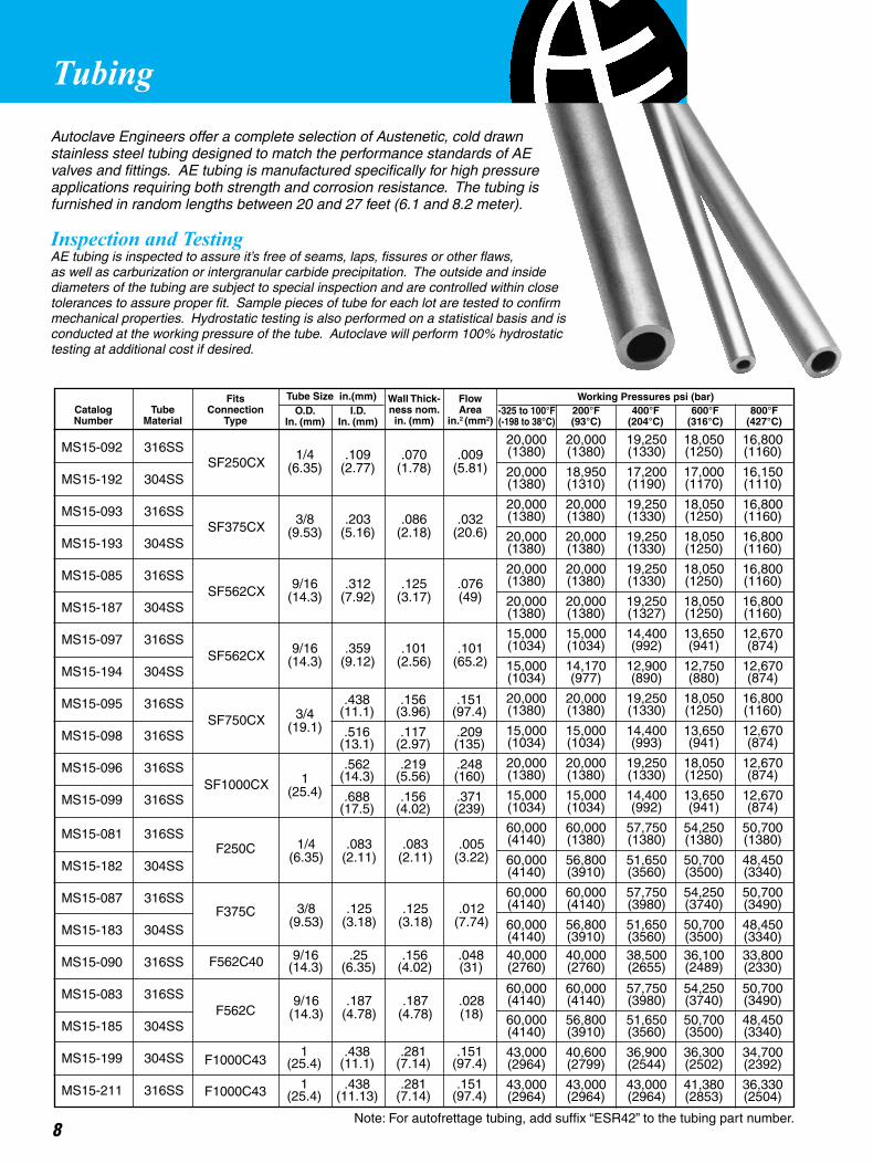
Autoclave Engineers offer a complete selection of Austenetic, cold drawn stainless steel tubing designed to match the performance standards of AE valves and fittings. AE tubing is manufactured specifically for high pressure applications requiring both strength and corrosion resistance. The tubing is furnished in random lengths between 20 and 27 feet (6.1 and 8.2 meter).
Inspection and TestingAE tubing is inspected to assure it’s free of seams, laps, fissures or other flaws, as well as carburization or intergranular carbide precipitation. The outside and inside diameters of the tubing are subject to special inspection and are controlled within close tolerances to assure proper fit. Sample pieces of tube for each lot are tested to confirm mechanical properties. Hydrostatic testing is also performed on a statistical basis and is conducted at the working pressure of the tube. Autoclave will perform 100% hydrostatic testing at additional cost if desired.
Fits Wall Thick- Flow Catalog Tube Connection ness nom. Area Number Material Type in. (mm) in.2 (mm2)
Working Pressures psi (bar)Tube Size in.(mm)O.D.
In. (mm)I.D.
In. (mm)200°F(93°C)
400°F(204°C)
600°F(316°C)
800°F(427°C)
-325 to 100°F(-198 to 38°C)
Tubing
8
20,000 20,000 19,250 18,050 16,800 (1380) (1380) (1330) (1250) (1160)
20,000 18,950 17,200 17,000 16,150 (1380) (1310) (1190) (1170) (1110)
20,000 20,000 19,250 18,050 16,800 (1380) (1380) (1330) (1250) (1160)
20,000 20,000 19,250 18,050 16,800 (1380) (1380) (1330) (1250) (1160)
20,000 20,000 19,250 18,050 16,800 (1380) (1380) (1330) (1250) (1160)
20,000 20,000 19,250 18,050 16,800 (1380) (1380) (1327) (1250) (1160)
15,000 15,000 14,400 13,650 12,670 (1034) (1034) (992) (941) (874)
15,000 14,170 12,900 12,750 12,670 (1034) (977) (890) (880) (874)
20,000 20,000 19,250 18,050 16,800 (1380) (1380) (1330) (1250) (1160)
15,000 15,000 14,400 13,650 12,670 (1034) (1034) (993) (941) (874)
20,000 20,000 19,250 18,050 12,670 (1380) (1380) (1330) (1250) (874)
15,000 15,000 14,400 13,650 12,670 (1034) (1034) (992) (941) (874)
60,000 60,000 57,750 54,250 50,700 (4140) (1380) (1380) (1380) (1380)
60,000 56,800 51,650 50,700 48,450 (4140) (3910) (3560) (3500) (3340)
60,000 60,000 57,750 54,250 50,700 (4140) (4140) (3980) (3740) (3490)
60,000 56,800 51,650 50,700 48,450 (4140) (3910) (3560) (3500) (3340)
60,000 60,000 57,750 54,250 50,700 (4140) (4140) (3980) (3740) (3490)
60,000 56,800 51,650 50,700 48,450 (4140) (3910) (3560) (3500) (3340)
43,000 40,600 36,900 36,300 34,700 (2964) (2799) (2544) (2502) (2392)
43,000 43,000 43,000 41,380 36,330 (2964) (2964) (2964) (2853) (2504)
1/4 .109 .070 .009 (6.35) (2.77) (1.78) (5.81)
3/8 .203 .086 .032 (9.53) (5.16) (2.18) (20.6)
9/16 .312 .125 .076 (14.3) (7.92) (3.17) (49)
9/16 .359 .101 .101 (14.3) (9.12) (2.56) (65.2)
1/4 .083 .083 .005 (6.35) (2.11) (2.11) (3.22)
3/8 .125 .125 .012 (9.53) (3.18) (3.18) (7.74)
9/16 .187 .187 .028 (14.3) (4.78) (4.78) (18)
3/4 (19.1)
1 (25.4)
.438 .156 .151 (11.1) (3.96) (97.4)
.516 .117 .209 (13.1) (2.97) (135)
.562 .219 .248 (14.3) (5.56) (160)
.688 .156 .371 (17.5) (4.02) (239)
MS15-092 316SS
MS15-192 304SS
MS15-093 316SS
MS15-193 304SS
MS15-085 316SS
MS15-187 304SS
MS15-097 316SS
MS15-194 304SS
MS15-095 316SS
MS15-098 316SS
MS15-096 316SS
MS15-099 316SS
MS15-081 316SS
MS15-182 304SS
MS15-087 316SS
MS15-183 304SS
MS15-090 316SS
MS15-083 316SS
MS15-185 304SS
MS15-199 304SS
MS15-211 316SS
Note: For autofrettage tubing, add suffix “ESR42” to the tubing part number.
SF250CX
SF375CX
SF562CX
SF562CX
SF750CX
SF1000CX
F250C
F375C
F562C
F1000C43
F1000C43
1 .438 .281 .151 (25.4) (11.1) (7.14) (97.4)
1 .438 .281 .151 (25.4) (11.13) (7.14) (97.4)
F562C40 9/16 .25 .156 .048 (14.3) (6.35) (4.02) (31)
40,000 40,000 38,500 36,100 33,800 (2760) (2760) (2655) (2489) (2330)
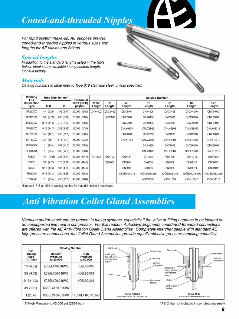
Coned-and-threaded Nipples
For rapid system make-up, AE supplies pre-cut, coned-and-threaded nipples in various sizes and lengths for AE valves and fittings.
Special lengthsIn addition to the standard lengths listed in the table below, nipples are available in any custom length. Consult factory.
MaterialsCatalog numbers in table refer to Type 316 stainless steel, unless specified.
Anti Vibration Collet Gland Assemblies
2.75” 3” 4” 6” 8” 10” 12” Length Length Length Length Length Length Length
Catalog NumberTube Size in.(mm)
9
Vibration and/or shock can be present in tubing systems, especially if the valve or fitting happens to be located on an unsupported line near a compressor. For this reason, Autoclave Engineers coned-and-threaded connections are offered with the AE Anti-Vibration Collet Gland Assemblies. Completely interchangeable with standard AE high pressure connections, the Collet Gland Assemblies provide equally effective pressure handling capability.
1/4 (6.35) KCBGLX40-316MC KCGL40-316
3/8 (9.53) KCBGLX60-316MC KCGL60-316
9/16 (14.3) KCBGLX90-316MC KCGL90-316
3/4 (19.1) KCBGLX120-316MC -
1 (25.4) KCBGLX160-316MC †KCBGLX160-316MC
O.D.Tubing
Sizein. (mm)
MediumPressureto 20,000
HighPressureto 60,000
Catalog Number Gland Nut
Collet gripstubing here for anti-vibration support
Collar*
Slotted collet
Collet body
Valve or fitting body
Line contactsealing
Series KCBGLXPressures to 20,000 psi (1380 bar)
Slotted collet
Valve or fitting body
Series KCGLPressures to 60,000 psi (1440 bar)
Gland Nut
Collet gripstubing here foranti-vibrationsupport
Collar*
Line contactsealing
*AE Collar not included in complete assembly.
CNX4402 CNX4403 CNX4404 CNX4406 CNX4408 CNX44010 CNX44012
CNX6603 CNX6604 CNX6606 CNX6608 CNX66010 CNX66012
CNX9904 CNX9906 CNX9908 CNX99010 CNX99012
CNLX9904 CNLX9906 CNLX9908 CNLX99010 CNLX99012
CNX1204 CNX1206 CNX1208 CNX12010 CNX12012
CNLX1204 CNLX1206 CNLX1208 CNLX12010 CNLX12012
CNX1606 CNX1608 CNX16010 CNX16012
CNLX1606 CNLX1608 CNLX16010 CNLX16012
CN4402 CN4403 CN4404 CN4406 CN4408 CN44010 CN44012
CN6603 CN6604 CN6606 CN6608 CN66010 CN66012
CN9904 CN9906 CN9908 CN99010 CN99012
40CN9904-316 40CN9906-316 40CN9908-316 40CN99010-316 40CN99012-316
43CN1606 43CN1608 43CN16010 43CN16012
Working Fits Pressure at Connection 100°F(38ºC) Type O.D. I.D. psi(bar)
† 1” High Pressure to 43,000 psi (2964 bar)
SF250CX 1/4 (6.35) .109 (2.77) 20,000 (1380)
SF375CX 3/8 (9.53) .203 (5.16) 20,000 (1380)
SF562CX 9/16 (14.3) .312 (7.92) 20,000 (1380)
SF562CX 9/16 (14.3) .359 (9.12) 15,000 (1034)
SF750CX 3/4 (19.1) .438 (11.1) 20,000 (1380)
SF750CX 3/4 (19.1) .515 (13.1) 15,000 (1034)
SF1000CX 1 (25.4) .562 (14.3) 20,000 (1380)
SF1000CX 1 (25.4) .688 (17.5) 15,000 (1034)
F250C 1/4 (6.35) .083 (2.11) 60,000 (4140)
F375C 3/8 (9.53) .125 (3.18) 60,000 (4140)
F562C 9/16 (14.3) .187 (4.78) 60,000 (4140)
F562C40 9/16 (14.3) .250 (6.35) 40,000 (2760)
F1000C43 1 (25.4) .438 (11.1) 43,000 (2964)
Note: Add -316 or -304 to catalog number for material choice if not shown.

Materials and features• Accuracy within ±0.5% of full scale range• Plastic dial cover/solid front aluminum alloy case• Blow-out back panel for pressure relief in the event of Bourdon tube failure• 316 Stainless steel Bourdon tubes**• Precision stainless steel movement for accuracy and resistance to atmospheric corrosion• Pointer zero adjustment located on front of gauge behind dial cover for convenience
Instrument quality gauges• Flush panel mounting - Interchangeable dial cover retaining rings are stocked to permit flush panel mounting of any instrument quality gauge. These will be furnished at an additional charge when specified on order -- add “PM” to order number.
• Optional electrical contact face - Available for all instrument quality gauges. With adjustable low and high electrical contacts, this option permits gauges to provide pressure control for automatic or remote operation, or for fail-safe set points.
** Bourdon Tube material for 0-80,000 psi (0-5116 bar) and 0-50,000 psi (0-3447 bar) gauge is Inconel 718. Bourdon Tube material for 0-30,000 psi (0-2068 bar) gauge is K Monel.
P-0499-CG 0-1000 10 4-1/2 P-0479-CG 0-1500 10 4-1/2 P-0480-CG 0-3000 20 4-1/2 P-0481-CG 0-5000 50 4-1/2 P-0482-CG 0-10,000 100 4-1/2 P-0483-CG 0-15,000 100 4-1/2 P-0487-CG 0-20,000 200 4-1/2 P-0488-CG** 0-30,000 200 6 P-0489-CG** 0-50,000 500 6 P-0490-CG** 0-80,000 1,000 6
MinorIntervalValue(psi)
Calibrated in psi Only
DialDiameter(inches)
PressureRange(psi)
CatalogNumber
P-0713 4-1/2 P-0714 6
Optional Electrical Contact Face
Catalog NumberFits Gauge Dial Diameter
(inches)
1/4" (F250C)Coned-and-Threaded Connection Furnished with Collar and Gland
10
AE Instrument Quality Gauges
Note: Gauges available with back connections. Add B to the base catalog number. Ex: P-047B-CG
11
Specialty Products
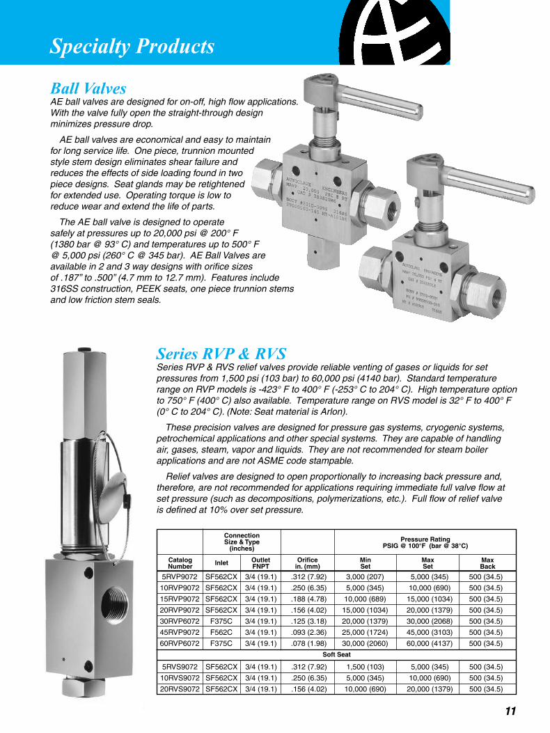
Ball ValvesAE ball valves are designed for on-off, high flow applications. With the valve fully open the straight-through design minimizes pressure drop.
AE ball valves are economical and easy to maintain for long service life. One piece, trunnion mounted style stem design eliminates shear failure and reduces the effects of side loading found in two piece designs. Seat glands may be retightened for extended use. Operating torque is low to reduce wear and extend the life of parts.
The AE ball valve is designed to operate safely at pressures up to 20,000 psi @ 200° F (1380 bar @ 93° C) and temperatures up to 500° F @ 5,000 psi (260° C @ 345 bar). AE Ball Valves are available in 2 and 3 way designs with orifice sizes of .187’’ to .500’’ (4.7 mm to 12.7 mm). Features include 316SS construction, PEEK seats, one piece trunnion stems and low friction stem seals.
Series RVP & RVS Series RVP & RVS relief valves provide reliable venting of gases or liquids for set pressures from 1,500 psi (103 bar) to 60,000 psi (4140 bar). Standard temperature range on RVP models is -423° F to 400° F (-253° C to 204° C). High temperature option to 750° F (400° C) also available. Temperature range on RVS model is 32° F to 400° F (0° C to 204° C). (Note: Seat material is Arlon).
These precision valves are designed for pressure gas systems, cryogenic systems, petrochemical applications and other special systems. They are capable of handling air, gases, steam, vapor and liquids. They are not recommended for steam boiler applications and are not ASME code stampable.
Relief valves are designed to open proportionally to increasing back pressure and, therefore, are not recommended for applications requiring immediate full valve flow at set pressure (such as decompositions, polymerizations, etc.). Full flow of relief valve is defined at 10% over set pressure.
5RVP9072 SF562CX 3/4 (19.1) .312 (7.92) 3,000 (207) 5,000 (345) 500 (34.5)
10RVP9072 SF562CX 3/4 (19.1) .250 (6.35) 5,000 (345) 10,000 (690) 500 (34.5)
15RVP9072 SF562CX 3/4 (19.1) .188 (4.78) 10,000 (689) 15,000 (1034) 500 (34.5)
20RVP9072 SF562CX 3/4 (19.1) .156 (4.02) 15,000 (1034) 20,000 (1379) 500 (34.5)
30RVP6072 F375C 3/4 (19.1) .125 (3.18) 20,000 (1379) 30,000 (2068) 500 (34.5)
45RVP9072 F562C 3/4 (19.1) .093 (2.36) 25,000 (1724) 45,000 (3103) 500 (34.5)
60RVP6072 F375C 3/4 (19.1) .078 (1.98) 30,000 (2060) 60,000 (4137) 500 (34.5)
ConnectionSize & Type
(inches)Pressure Rating
PSIG @ 100°F (bar @ 38°C)
CatalogNumber Inlet Outlet
FNPTOrifice
in. (mm)MinSet
MaxSet
MaxBack
Soft Seat
5RVS9072 SF562CX 3/4 (19.1) .312 (7.92) 1,500 (103) 5,000 (345) 500 (34.5)
10RVS9072 SF562CX 3/4 (19.1) .250 (6.35) 5,000 (345) 10,000 (690) 500 (34.5)
20RVS9072 SF562CX 3/4 (19.1) .156 (4.02) 10,000 (690) 20,000 (1379) 500 (34.5)
Specialty Products
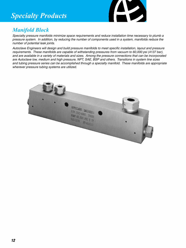
Manifold BlockSpecialty pressure manifolds minimize space requirements and reduce installation time necessary to plumb a pressure system. In addition, by reducing the number of components used in a system, manifolds reduce the number of potential leak joints.
Autoclave Engineers will design and build pressure manifolds to meet specific installation, layout and pressure requirements. These manifolds are capable of withstanding pressures from vacuum to 60,000 psi (4137 bar), and are available in a variety of materials and sizes. Among the pressure connections that can be incorporated are Autoclave low, medium and high pressure, NPT, SAE, BSP and others. Transitions in system line sizes and tubing pressure series can be accomplished through a specialty manifold. These manifolds are appropriate wherever pressure tubing systems are utilized.
12
13
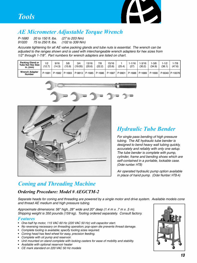
AE Micrometer Adjustable Torque WrenchP-1680 20 to 150 ft. lbs. (27 to 203 Nm)91020 75 to 250 ft. lbs. (102 to 339 Nm)
Accurate tightening for all AE valve packing glands and tube nuts is essential. The wrench can be adjusted to the ranges shown and is used with interchangeable wrench adapters for hex sizes from 1/2" through 1-7/8". Part numbers for wrench adapters are listed on chart.
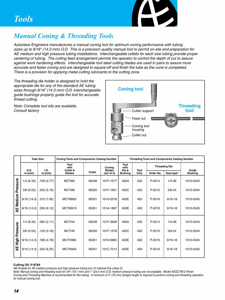
Hydraulic Tube Bender
For single pass bending of high pressure tubing. The AE hydraulic tube bender is designed to bend heavy wall tubing quickly, accurately and reliably with only one setup. The tube bender is complete with pump, cylinder, frame and bending shoes which are self-contained in a portable, lockable case. (Order number: HTB)
Air operated hydraulic pump option available in place of hand pump. (Order Number: HTB-A)
Packing Gland orTube Nut Hex Size
in. (mm)
1/2 9/16 5/8 3/4 13/16 7/8 15/16 1 1-1/16 1-3/16 1-3/8 1-1/2 1-7/8 (12.7) (14.3) (15.9) (19.05) (20.6) (22.2) (23.8) (25.4) (27) (30.2) (34.9) (38.1) (47.6) P-1681 P-1682 P-1683 P-9813 P-1685 P-1686 P-1687 P-9901 P-1688 P-1689 P-1690 P-6040 P-10076Wrench Adapter
Number
Coning and Threading MachineOrdering Procedure: Model # AEGCTM-2Separate heads for coning and threading are powered by a single motor and drive system. Available models cone and thread AE medium and high pressure tubing.
Approximate dimensions: 56" high, 28" wide and 20" deep (1.4 m x .7 m x .5 m). Shipping weight is 350 pounds (159 kg). Tooling ordered separately. Consult factory.
Features• One-half hp motor, 115 VAC 60 Hz (220 VAC 50 Hz) volt capacitor start.• No reversing necessary on threading operation; pop-open die prevents thread damage.• Complete tooling is available; specify tooling sizes required.• Coning head has feed wheel for easy, precision feeding. • Complete with oil pump and reservoir.• Unit mounted on stand complete with locking casters for ease of mobility and stability.• Available with optional reservoir heater• CE mark standard on 220 VAC 50 Hz models
Tools
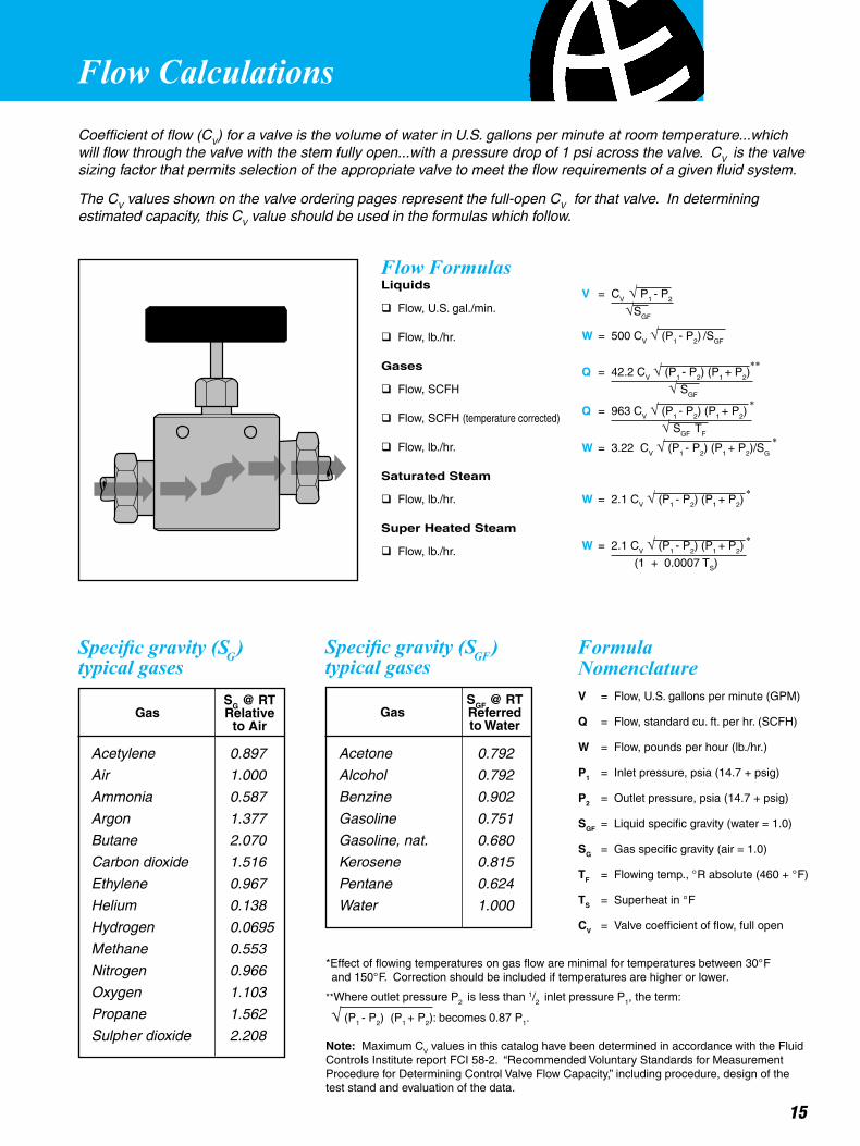
Autoclave Engineers manufactures a manual coning tool for optimum coning performance with tubing sizes up to 9/16" (14.3 mm) O.D. This is a precision quality manual tool to permit on-site end preparation for AE medium and high pressure tubing installations. Interchangeable collets for each size tubing provide proper centering of tubing. The cutting feed arrangement permits the operator to control the depth of cut to assure against work hardening effects. Interchangeable tool steel cutting blades are used in pairs to assure more accurate and faster coning and are designed to square-off and finish the tube as the cone is completed. There is a provision for applying metal cutting lubricants to the cutting zone.
The threading die holder is designed to hold the appropriate die for any of the standard AE tubing sizes through 9/16” (14.3 mm) O.D. Interchangeable guide bushings properly guide the tool for accurate thread cutting.
Note: Complete tool kits are available. Consult factory
Coning Tools and Components Catalog NumberTube Size
O.D.in.(mm)
I.D.in.(mm)
Toolwith
Collet &Blades
Toolwith
Die &BushingCollet
ConingBlades
(set of 2)ToolOnly
Guide BushingSize-type*Order No.
Threading Tools and Components Catalog Number
Threading Die
AE
Hig
h P
ress
ure
AE
Med
ium
Pre
ssur
e
1/4 (6.35) .109 (2.77) MCTM4 90248 101F-1577 402A 402 P-0214 1/4-28 1010-0343
3/8 (9.53) .203 (5.16) MCTM6 90250 101F-1601 402C 402 P-0215 3/8-24 1010-0344
9/16 (14.3) .312 (7.92) MCTM920 90251 1010-5218 402E 402 P-0216 9/16-18 1010-0345
9/16 (14.3) .359 (9.12) MCTM910 90251 101A-1897 402E 402 P-0216 9/16-18 1010-0345
1/4 (6.35) .083 (2.11) MCTH4 90248 101F-3939 402A 402 P-0214 1/4-28 1010-0343
3/8 (9.53) .125 (3.18) MCTH6 90250 101F-1578 402C 402 P-0215 3/8-24 1010-0344
9/16 (14.3) .188 (4.78) MCTH960 90251 1010-0883 402E 402 P-0216 9/16-18 1010-0345
9/16 (14.3) .250 (6.35) MCTH940 90251 101C-7214 402E 402 P-0216 9/16-18 1010-0345
Tools
Manual Coning & Threading Tools
Coning tool
Cutter support
Feed nut
Collet nut
Coning toolhousing
Threadingtool
Cutting Oil: P-8784• All threads for AE medium pressure and high pressure tubing are LH national fine (class 2).Note: Manual coning and threading tools for 3/4" (19.1 mm) and 1" (25.4 mm) O.D. medium pressure tubing are not available. Model AEGCTM-2 Power Coning-and-Threading Machine is recommended for this tubing. A minimum of 3" (76 mm) straight length is required to perform coning and threading operation for manual coning tool.
14
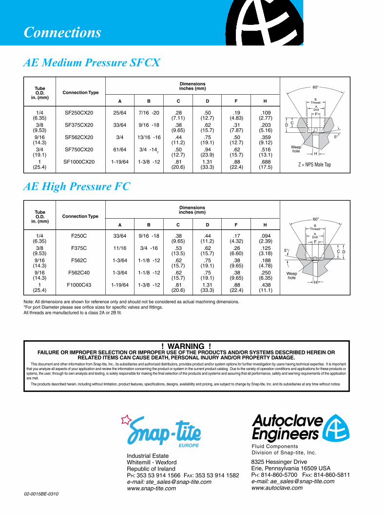
Flow Calculations
15
Coefficient of flow (CV) for a valve is the volume of water in U.S. gallons per minute at room temperature...which will flow through the valve with the stem fully open...with a pressure drop of 1 psi across the valve. CV is the valve sizing factor that permits selection of the appropriate valve to meet the flow requirements of a given fluid system.
The CV values shown on the valve ordering pages represent the full-open CV for that valve. In determining estimated capacity, this CV value should be used in the formulas which follow.
Formula NomenclatureV = Flow, U.S. gallons per minute (GPM)
Q = Flow, standard cu. ft. per hr. (SCFH)
W = Flow, pounds per hour (lb./hr.)
P1 = Inlet pressure, psia (14.7 + psig)
P2 = Outlet pressure, psia (14.7 + psig)
SGF = Liquid specific gravity (water = 1.0)
SG = Gas specific gravity (air = 1.0)
TF = Flowing temp., °R absolute (460 + °F)
TS = Superheat in °F
CV = Valve coefficient of flow, full open
Acetone 0.792
Alcohol 0.792
Benzine 0.902
Gasoline 0.751
Gasoline, nat. 0.680
Kerosene 0.815
Pentane 0.624
Water 1.000
Specific gravity (SG )typical gases
SG @ RTRelative
to AirGas
Acetylene 0.897
Air 1.000
Ammonia 0.587
Argon 1.377
Butane 2.070
Carbon dioxide 1.516
Ethylene 0.967
Helium 0.138
Hydrogen 0.0695
Methane 0.553
Nitrogen 0.966
Oxygen 1.103
Propane 1.562
Sulpher dioxide 2.208
Specific gravity (SGF)typical gases
SGF @ RTReferredto Water
Gas
*Effect of flowing temperatures on gas flow are minimal for temperatures between 30°F and 150°F. Correction should be included if temperatures are higher or lower.
**Where outlet pressure P2 is less than 1/2 inlet pressure P1, the term:
√ (P1 - P2) (P1 + P2): becomes 0.87 P1.
Note: Maximum CV values in this catalog have been determined in accordance with the Fluid Controls Institute report FCI 58-2. “Recommended Voluntary Standards for Measurement Procedure for Determining Control Valve Flow Capacity,” including procedure, design of the test stand and evaluation of the data.
Flow FormulasLiquids
q Flow, U.S. gal./min.
q Flow, lb./hr.
Gases
q Flow, SCFH
q Flow, SCFH (temperature corrected)
q Flow, lb./hr.
Saturated Steam
q Flow, lb./hr.
Super Heated Steam
q Flow, lb./hr.
V = CV √ P1 - P2
√SGF
W = 500 CV √ (P1 - P2) /SGF
Q = 42.2 CV √ (P1 - P2) (P1 + P2)
√ SGF
Q = 963 CV √ (P1 - P2) (P1 + P2)
√ SGF TF
W = 3.22 CV √ (P1 - P2) (P1 + P2)/SG
W = 2.1 CV √ (P1 - P2) (P1 + P2)
W = 2.1 CV √ (P1 - P2) (P1 + P2)
(1 + 0.0007 TS)
*
*
*
*
**
Connections
! WARNING !FAILURE OR IMPROPER SELECTION OR IMPROPER USE OF THE PRODUCTS AND/OR SYSTEMS DESCRIBED HEREIN OR
RELATED ITEMS CAN CAUSE DEATH, PERSONAL INJURY AND/OR PROPERTY DAMAGE. This document and other information from Snap-tite, Inc., its subsidiaries and authorized distributors, provides product and/or system options for further investigation by users having technical expertise. It is important that you analyze all aspects of your application and review the information concerning the product or system in the current product catalog. Due to the variety of operation conditions and applications for these products or sytems, the user, through its own analysis and testing, is solely responsible for making the final selection of the products and systems and assuring that all performance, safety and warning requirements of the application are met.
The products described herein, including without limitation, product features, specifications, designs, availability and pricing, are subject to change by Snap-tite, Inc. and its subsidiaries at any time without notice.
02-0015BE-0310
1/4 SF250CX20 25/64 7/16 -20 .28 .50 .19 .109 (6.35) (7.11) (12.7) (4.83) (2.77) 3/8 SF375CX20 33/64 9/16 -18 .38 .62 .31 .203 (9.53) (9.65) (15.7) (7.87) (5.16) 9/16 SF562CX20 3/4 13/16 -16 .44 .75 .50 .359 (14.3) (11.2) (19.1) (12.7) (9.12) 3/4 SF750CX20 61/64 3/4 -14z .50 .94 .62 .516 (19.1) (12.7) (23.9) (15.7) (13.1) 1 SF1000CX20 1-19/64 1-3/8 -12 .81 1.31 .88 .688 (25.4) (20.6) (33.3) (22.4) (17.5)
Dimensionsinches (mm)Tube
O.D.in. (mm)
A B C D F H
Connection Type
AE Medium Pressure SFCX
1/4 F250C 33/64 9/16 -18 .38 .44 .17 .094 (6.35) (9.65) (11.2) (4.32) (2.39) 3/8 F375C 11/16 3/4 -16 .53 .62 .26 .125 (9.53) (13.5) (15.7) (6.60) (3.18) 9/16 F562C 1-3/64 1-1/8 -12 .62 .75 .38 .188 (14.3) (15.7) (19.1) (9.65) (4.78) 9/16 F562C40 1-3/64 1-1/8 -12 .62 .75 .38 .250 (14.3) (15.7) (19.1) (9.65) (6.35) 1 F1000C43 1-19/64 1-3/8 -12 .81 1.31 .88 .438 (25.4) (20.6) (33.3) (22.4) (11.1)
Dimensionsinches (mm)Tube
O.D.in. (mm)
A B C D F H
Connection Type
AE High Pressure FC
Note: All dimensions are shown for reference only and should not be considered as actual machining dimensions.*For port Diameter please see orifice sizes for specific valves and fittings.All threads are manufactured to a class 2A or 2B fit.
8325 Hessinger DriveErie, Pennsylvania 16509 USAPh: 814-860-5700 Fax: 814-860-5811e-mail: [email protected]
Industrial EstateWhitemill - WexfordRepublic of IrelandPh: 353 53 914 1566 Fax: 353 53 914 1582e-mail: [email protected]
Z = NPS Male Tap
F
BThread
ADrill
5°
Weephole
60°
C D
H
D C
H
BThread
ADrill
5°
60°
Weephole
F