Embed Size (px)
Citation preview

Note 1) Since the switch bracket (made from nylon) are affected in an environment where alcohol, chloroform, methylamines, hydrochloric acid or sulfuric acid is splashed over, so it cannot be used. Please contact SMC regarding other chemicals.
Note 2) As the indicator LED is projected from the switch unit, indicator LED may be damaged if the switch bracket is fixed on the indicator LED.
Note 3) The D-A3lA/A44A/G39A/K39A cannot be mounted on the centralized piping type CDM2lP series.
Auto switch modelBore size (mm)
ø20 ø25 ø32 ø40
D-M9l(V)D-M9lW(V)D-A9l(V)
BM5-020(A set of a, b, c, d)
BM5-025(A set of a, b, c, d)
BM5-032(A set of a, b, c, d)
BM5-040(A set of a, b, c, d)
D-M9lA(V) Note 2)BM5-020S
(A set of b, c, d, e)BM5-025S
(A set of b, c, d, e)BM5-032S
(A set of b, c, d, e)BM5-040S
(A set of b, c, d, e)
D-H7lD-H7lWD-H7NFD-C7l/C80D-C73C/C80C
BM2-020A(A set of band and screw)
BM2-025A(A set of band and screw)
BM2-032A(A set of band and screw)
BM2-040A(A set of band and screw)
D-H7BABM2-020AS
(A set of band and screw)BM2-025AS
(A set of band and screw)BM2-032AS
(A set of band and screw)BM2-040AS
(A set of band and screw)
D-B5l/B64D-B59WD-G5NT
BA2-020(A set of band and screw)
BA2-025(A set of band and screw)
BA2-032(A set of band and screw)
BA2-040(A set of band and screw)
D-A3lA/A44A Note 3)
D-G39A/K39ABM3-020
(A set of band and screw)BM3-025
(A set of band and screw)BM3-032
(A set of band and screw)BM3-040
(A set of band and screw)
Auto switch
Switch holder(Zinc)
b
Auto switch mounting screwd
Auto switch mounting bandc
Switch bracket (Resin)Transparent (Nylon) Note 1)
White (PBT)
a
e
Band Mounting Brackets Set Part No.Set part no. Contents
BM2-lllA(S)* S: Stainless steel screw
Auto switch mounting band (c)Auto switch mounting screw (d)
BJ4-1 Switch bracket (White/PBT) (e)Switch holder (b)
BJ5-1 Switch bracket (Transparent/Nylon) (a)Switch holder (b)
Other than the applicable auto switches listed in “How to Order”, the following auto switches are mountable.Refer to the WEB catalog or the Best Pneumatics No. 2 for the detailed specifications.
* With pre-wired connector is also available for solid state auto switches. For details, refer to the WEB catalog or the Best Pneumatics No. 2.* Normally closed (NC = b contact) solid state auto switches (D-F9G/F9H) are also available. For details, refer to the WEB catalog or the Best Pneumatics No. 2.
Type Model Electrical entry Features
Solid state
D-H7A1, H7A2, H7B
Grommet (In-line)
—
D-H7NW, H7PW, H7BW Diagnostic indication (2-color indication)
D-H7BA Water resistant (2-color indication)
D-G5NT With timer
ReedD-B53, C73, C76
Grommet (In-line)—
D-C80 Without indicator light
Auto Switch Mounting Brackets/Part No.
99
Series CM2

Switch bracket (Resin)Transparent (Nylon) Note 1)
White (PBT)
a
e
Auto switch
Switch holderb
Auto switchmounting screw
d
Auto switch mounting bandc
Note 1) Since the switch bracket (made from nylon) are affected in an environment where alcohol, chloroform, methylamines, hydrochloric acid or sulfuric acid is splashed over, so it cannot be used. Please contact SMC regarding other chemicals.
Note 2) As the indicator LED is projected from the switch unit, indicator LED may be damaged if the switch bracket is fixed on the indicator LED.
[Stainless Steel Mounting Screw]The following stainless steel mounting screw kit is available. Use it in accordance with the operating environment.(Since the auto switch mounting bracket is not included, order it separately.)
BBA3: D-B5/B6/G5/K5 typesNote 3) Refer to the WEB catalog or the Best Pneumatics No. 2 for details on the BBA3.
When the D-G5BA type auto switch is shipped independently, the BBA3 is attached.
Auto switch modelBore size (mm)
20 25 32 40 50 63 80 100D-M9(V)D-M9W(V)D-A9(V)
BMA3-020(A set of a, b, c, d)
BMA3-025(A set of a, b, c, d)
BMA3-032(A set of a, b, c, d)
BMA3-040(A set of a, b, c, d)
BMA3-050(A set of a, b, c, d)
BMA3-063(A set of a, b, c, d)
— —
D-M9A(V) Note 2) BMA3-020S(A set of b, c, d, e)
BMA3-025S(A set of b, c, d, e)
BMA3-032S(A set of b, c, d, e)
BMA3-040S(A set of b, c, d, e)
BMA3-050S(A set of b, c, d, e)
BMA3-063S(A set of b, c, d, e)
— —
D-H7D-H7WD-H7NFD-C7/C80D-C73C/C80C
BMA2-020A(A set of band and screw)
BMA2-025A(A set of band and screw)
BMA2-032A(A set of band and screw)
BMA2-040A(A set of band and screw)
BMA2-050A(A set of band and screw)
BMA2-063A(A set of band and screw)
— —
D-H7BA BMA2-020AS(A set of band and screw)
BMA2-025AS(A set of band and screw)
BMA2-032AS(A set of band and screw)
BMA2-040AS(A set of band and screw)
BMA2-050AS(A set of band and screw)
BMA2-063AS(A set of band and screw)
— —
D-G5/K59D-G5W/K59WD-G5BA/G59FD-G5NTD-B5/B64D-B59WD-G5NB
BA-01(A set of band and screw)
BA-02(A set of band and screw)
BA-32(A set of band and screw)
BA-04(A set of band and screw)
BA-05(A set of band and screw)
BA-06(A set of band and screw)
BA-08(A set of band and screw)
BA-10(A set of band and screw)
∗ Band (c) is mounted so that the projected part is on the internal side (contact side with the tube).
Band Mounting Brackets Set Part No.Set part no. Contents
BMA2-A(S)∗ S: Stainless steel screw
· Auto switch mounting band (c)· Auto switch mounting screw (d)
BJ4-1 · Switch bracket (White/PBT) (e)· Switch holder (b)
BJ5-1 · Switch bracket (Transparent/Nylon) (a)· Switch holder (b)
Auto Switch Mounting Brackets/Part No.
73
Series CG1

∗: Values which include hysteresis are for guideline purposes only, they are not a guarantee (assuming approximately ±30% dispersion) and may change substantially depending on the ambient environment.
[mm]
Auto switch
mountingAuto switch model
Bore size [mm]
6 10 16
Band mounting
D-M9lD-M9lVD-M9lWD-M9lWVD-A9lD-A9lV
BJ6-006(A set of a, b, d, f)
BJ6-010(A set of a, b, c, d)
BJ6-016(A set of a, b, c, d)
D-M9lA ∗2
D-M9lAV∗2BJ6-006S
(A set of a, b, d, g)BJ6-010S
(A set of a, b, d, e)BJ6-016S
(A set of a, b, d, e)
Switch bracket (Resin)Transparent (Nylon)∗1
Transparent blue (Nylon)∗1
White (PBT)
c
f
Black (PBT)ge
Switch holder(Zinc die-casted)
d
Auto switch mounting banda
Auto switch mounting screwb
Band mounting
D-H7l/H7lWD-H7BA/H7NFD-C7l/C80D-C73C/C80C
BJ2-006(A set of band and
screw)
BJ2-010(A set of band and
screw)
BJ2-016(A set of band and
screw)
∗4
Rail mounting
D-M9lD-M9lVD-M9lWD-M9lWVD-M9lA ∗4
D-M9lAV∗4
D-A9lD-A9lV
—
BQ2-012 (S)(A set of a and b)
BQ2-012 (S)(A set of a and b)
Set screw(Accessory)
Auto switchmounting screw
b
BQ2-012BQ2-012S
Auto switchmounting bracket
a
Nut (Cylinder accessory)
Auto switch modelBore size
6 10 16
Ban
d m
ount
ing
D-M9l/M9lVD-M9lW/M9lWVD-M9lA/M9lAV
2 2.5 3
D-A9l 4.5 6 7
D-H7l/H7lWD-H7BA/H7NF 3 4 4
D-H7C 5 8 9
D-C7l/C80/C73C/C80C 6 7 7
Rai
l mou
ntin
g
D-M9l/M9lVD-M9lW/M9lWVD-M9lA/M9lAV
— 3 3.5
D-A9l/A9lV — 6 6.5
D-F7l/J79/F7lW/J79WD-F7lV/F7lWV/F79FD-J79C/F7BA/F7BAVD-F7NT
— 5 5
D-A7l/A80/A7H/A80HD-A73C/A80C — 8 9
D-A79W — 11 13
∗1: Since the switch bracket (made from nylon) are affected in an environment where alcohol, chloroform, methylamines, hydrochloric acid or sulfuric acid is splashed over, so it cannot be used. Please contact SMC regarding other chemicals.
∗2: As the indicator LED is projected from the auto switch unit, indicator LED may be damaged if the switch bracket is fixed on the indicator LED.
∗3: When the cylinder is shipped, the auto switch mounting bracket and the auto switch will be included.
∗4: For D-M9lA(V), order the BQ2-012S, which uses stainless steel mounting screws.
[Stainless Steel Mounting Screw]The following stainless steel mounting screw kit is available. Use it in accordance with the operating environment. (Since the auto switch mounting bracket is not included, order it separately.)
BBA4: For D-C7/C8/H7 types∗5: Refer to the WEB catalog or the Best Pneumatics No. 2 for details on the BBA4.
When the D-H7BA type auto switch is shipped independently, the BBA4 is attached.
Set part no. ContentsBore size [mm]
6 10 16
BJ2-lll • Auto switch mounting band (a)• Auto switch mounting screw (b)
BJ2-006 BJ2-010 BJ2-016
BJ4-1 • Switch bracket (White/PBT) (e)• Switch holder (d)
— V V
BJ4-2 • Switch bracket (Black/PBT) (g)• Switch holder (d)
V — —
BJ5-1 • Switch bracket (Transparent/Nylon) (c)∗1
• Switch holder (d)— V V
BJ5-2 • Switch bracket (Transparent blue/Nylon) (f)∗1
• Switch holder (d)V — —
Band Mounting Brackets Set Part No.
Operating Range Auto Switch Mounting Brackets/Part No.
107
Series CJ2

53
Series NCM
Auto switch modelBore size
D-M9�(V)D-M9�W(V)D-A9�(V)
Auto Switch Mounting
D-G5NTLD-B5�/B59W/B64
D-H7�D-H7�WD-H7BALD-H7NFD-C7�/80D-C73C/80C
D-H7BAL switch is set on the cylinder with the stainless steel screws (BBA4) above when shipped.When only a switch is shipped independently, BBA4 screws are attached.
Stainless steel screw setThe set of stainless steel mounting screws described below is available and can be used depending on the operating environment. As auto switch bracket is not included, order separately.
Auto Switch Mounting Bracket Part No.
NCMB-200BJ3-1
Note 1)
200
NBM2-150BJ3-1
Note 1)
150
NBM2-125BJ3-1
Note 1)
125
NBM2-106BJ3-1
Note 1)
106
NBM2-088BJ3-1
Note 1)
088
NBM2-075BJ3-1
Note 1)
075
BJ2-015BJ3-1
Note 1)
056
BJ2-012BJ3-1
Note 1)
044
NCMA-200NBA-150NBA-125NBA-106NBA-088NBA-075––
NCMB-200NBM2-150NBM2-125NBM2-088NBM2-088NBM2-075BJ2-015BJ2-012
Part no. Applicable auto switchmounting bracket part no.
Applicableauto switch
Content
BBA3
BBA4
D-G5NTLD-B5��D-B64
D-H7��D-C7��D-C80�
Detailed Contents of Stainless Steel Mounting Screw Sets
SizeDescription
M4X0.7X22L
Qty.
1 NBA-075/088/106/125/150NCMA-200
Auto switchmounting screw
M3X0.5X14L 1BJ2-012/015NBM2-075/088/106/125/150NCMB-200
Auto switchmounting screw
Note 1) Two types of auto switch mounting brackets are used as a set.Note 2) D-G5NTL, B5�, B64, B59W cannot be mounted on models with bore size 044 and 056.
a Switch mounting band
bSwitch mounting screw
dSwitch holder
(Resin)
Set screw (Not used)
Auto switch
eSwitch spacer(Stainless steel)
cSwitch bracket(Stainless steel)
Cylinder tubing
A set of the parts marked a and b in the diagram is used for types BJ2-���, NBM2-���, and NCMB-200.A set of the parts marked c , d and e in the diagram is used for type BJ3-1.
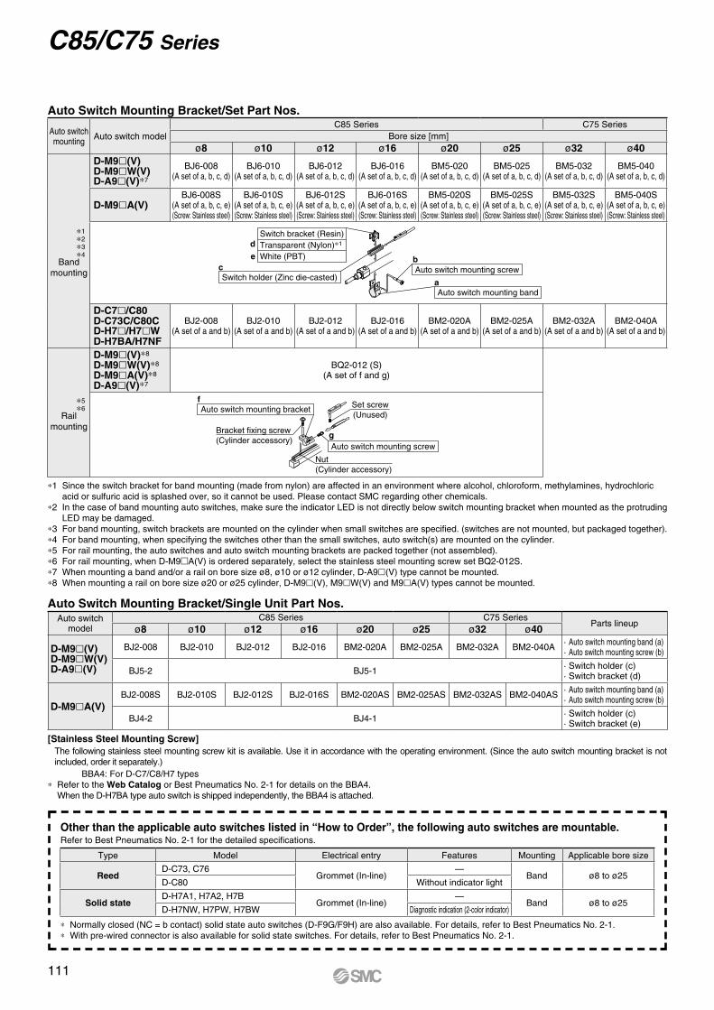
C85/C75 Series
Auto Switch Mounting Bracket/Set Part Nos.
Auto Switch Mounting Bracket/Single Unit Part Nos.
*1 Since the switch bracket for band mounting (made from nylon) are affected in an environment where alcohol, chloroform, methylamines, hydrochloric acid or sulfuric acid is splashed over, so it cannot be used. Please contact SMC regarding other chemicals.
*2 In the case of band mounting auto switches, make sure the indicator LED is not directly below switch mounting bracket when mounted as the protruding LED may be damaged.
*3 For band mounting, switch brackets are mounted on the cylinder when small switches are specified. (switches are not mounted, but packaged together).*4 For band mounting, when specifying the switches other than the small switches, auto switch(s) are mounted on the cylinder.*5 For rail mounting, the auto switches and auto switch mounting brackets are packed together (not assembled).*6 For rail mounting, when D-M9mA(V) is ordered separately, select the stainless steel mounting screw set BQ2-012S.*7 When mounting a band and/or a rail on bore size ø8, ø10 or ø12 cylinder, D-A9l(V) type cannot be mounted.*8 When mounting a rail on bore size ø20 or ø25 cylinder, D-M9l(V), M9lW(V) and M9lA(V) types cannot be mounted.
Other than the applicable auto switches listed in “How to Order”, the following auto switches are mountable.Refer to Best Pneumatics No. 2-1 for the detailed specifications.
* Normally closed (NC = b contact) solid state auto switches (D-F9G/F9H) are also available. For details, refer to Best Pneumatics No. 2-1.* With pre-wired connector is also available for solid state switches. For details, refer to Best Pneumatics No. 2-1.
Type Model Electrical entry Features Mounting Applicable bore size
ReedD-C73, C76
Grommet (In-line)—
Band ø8 to ø25D-C80 Without indicator light
Solid stateD-H7A1, H7A2, H7B
Grommet (In-line)—
Band ø8 to ø25D-H7NW, H7PW, H7BW Diagnostic indication (2-color indicator)
Auto switchmounting Auto switch model
C85 Series C75 SeriesBore size [mm]
ø8 ø10 ø12 ø16 ø20 ø25 ø32 ø40
*1*2*3*4
Band mounting
D-M9l(V)D-M9lW(V)D-A9l(V)*7
BJ6-008(A set of a, b, c, d)
BJ6-010(A set of a, b, c, d)
BJ6-012(A set of a, b, c, d)
BJ6-016(A set of a, b, c, d)
BM5-020(A set of a, b, c, d)
BM5-025(A set of a, b, c, d)
BM5-032(A set of a, b, c, d)
BM5-040(A set of a, b, c, d)
D-M9lA(V)BJ6-008S
(A set of a, b, c, e)(Screw: Stainless steel)
BJ6-010S(A set of a, b, c, e)(Screw: Stainless steel)
BJ6-012S(A set of a, b, c, e)(Screw: Stainless steel)
BJ6-016S(A set of a, b, c, e)(Screw: Stainless steel)
BM5-020S(A set of a, b, c, e)(Screw: Stainless steel)
BM5-025S(A set of a, b, c, e)(Screw: Stainless steel)
BM5-032S(A set of a, b, c, e)(Screw: Stainless steel)
BM5-040S(A set of a, b, c, e)(Screw: Stainless steel)
Switch holder (Zinc die-casted)c
Switch bracket (Resin)Transparent (Nylon)∗1
White (PBT)
d
e
Auto switch mounting banda
Auto switch mounting screwb
D-C7l/C80D-C73C/C80CD-H7l/H7lWD-H7BA/H7NF
BJ2-008(A set of a and b)
BJ2-010(A set of a and b)
BJ2-012(A set of a and b)
BJ2-016(A set of a and b)
BM2-020A(A set of a and b)
BM2-025A(A set of a and b)
BM2-032A(A set of a and b)
BM2-040A(A set of a and b)
*5*6
Rail mounting
D-M9l(V)*8
D-M9lW(V)*8
D-M9lA(V)*8
D-A9l(V)*7
BQ2-012 (S)(A set of f and g)
Auto switch mounting bracketf
Nut(Cylinder accessory)
Auto switch mounting screwg
Set screw(Unused)
Bracket fixing screw(Cylinder accessory)
Auto switch model
C85 Series C75 SeriesParts lineup
ø8 ø10 ø12 ø16 ø20 ø25 ø32 ø40
D-M9l(V)D-M9lW(V)D-A9l(V)
BJ2-008 BJ2-010 BJ2-012 BJ2-016 BM2-020A BM2-025A BM2-032A BM2-040A · Auto switch mounting band (a)· Auto switch mounting screw (b)
BJ5-2 BJ5-1 · Switch holder (c)· Switch bracket (d)
D-M9lA(V)BJ2-008S BJ2-010S BJ2-012S BJ2-016S BM2-020AS BM2-025AS BM2-032AS BM2-040AS · Auto switch mounting band (a)
· Auto switch mounting screw (b)
BJ4-2 BJ4-1 · Switch holder (c)· Switch bracket (e)
[Stainless Steel Mounting Screw]The following stainless steel mounting screw kit is available. Use it in accordance with the operating environment. (Since the auto switch mounting bracket is not included, order it separately.) BBA4: For D-C7/C8/H7 types
* Refer to the Web Catalog or Best Pneumatics No. 2-1 for details on the BBA4. When the D-H7BA type auto switch is shipped independently, the BBA4 is attached.
111

q
w
q
w
ø12 to ø25 ø32
—
ø40 to ø100
D-A7/A80 D-A73C/A80CD-A7H/A80HD-A79WD-F7/J79D-F7VD-J79CD-F7W/J79WD-F7WVD-F7BA/F7BAVD-F79F/F7NT
D-P4DW
BQ-1 BQ-2
BQP1-050
D-A9D-A9VD-M9D-M9VD-M9WD-M9WVD-M9AD-M9AV
ø12, ø16, ø20, ø25 ø32 to ø100
A
B
C
Applicable Cylinder Series: CDQP2, CDQP2-S/-T (Axial piping)
Auto Switch Mounting Brackets/Part No.4
Auto switchmounting surface
Auto switchmodel
Bore size (mm)
Auto switch mounting surface
A/B/C side
Auto switch mounting surface
Auto switch mounting rail side only
Note 1) When shipping cylinders, auto switch mounting brackets and auto switches are shipped together.
BQ-1BQ2-012
Two kinds of auto switch brackets are used as a set.
BQ-2BQ2-012
Two kinds of auto switch brackets are used as a set.
Set screw(Not used)
Set screw(Not used)
Bore size (mm)Auto switch model
Note 2) When shipping cylinders, auto switch mounting brackets and auto switches are shipped together.However, when the D-P4DW type with ø40 to ø100 is mounted, the auto switch is assembled at the time of shipment.
Note 3) Refer to pages 1658 to 1660 for further information on auto switch mounting method.
[Stainless Steel Mounting Screw Kit]The following stainless steel mounting screw kit (with nuts) is available. Use it in accordance with the operating environment. (Since auto switch spacer (for BQ-2) is not included, order BQ-2 separately.) BBA2: For D-A7/A8/F7/J7 typesThe above stainless steel screws are used when a cylinder is shipped with the D-F7BA/F7BAV auto switches.When only an auto switch is shipped independently, BBA2 is attached.Note 4) Refer to page 1659 for details of BBA2.Note 5) When the D-M9A(V) type is mounted, order auto switch mounting
brackets BQ2-012S, BQ-2 or the stainless steel mounting screw kit BBA2 separately.
Auto Switch Mounting Bracket/WeightApplicable bore size
ø12 to ø25
ø32 to ø100
ø12 to ø25
ø40 to ø100
Weight (g)
1.5
1.5
5
16
BQ-1
BQ-2
BQ2-012
BQP1-050
Mounting bracket part no.
Compact Cylinder: Axial Piping Series CDQP2
911
CUJ
CU
CQSCQ2-Z
RQ
CQM
CQUMU-Z
D-
-XTechnicaldata
CQ2-Z

q
w
D-A9D-A9VD-M9D-M9VD-M9WD-M9WVD-M9AD-M9AV
ø20, ø25 ø63, ø80, ø100ø32, ø40, ø50
B
C A C
B
AC
B
A
BQ-2
BQ2-012
BQP1-050
1008063504032
BQP1-050—
D-A7/A80D-A73C/A80CD-A7H/A80HD-A79WD-F7/J79D-F7VD-J79CD-F7W/J79WD-F7WVD-F7BA/F7BAVD-F79F/F7NT
D-P4DW
BQ-2
1.5
5
16
Auto switchmounting surface
Auto switchmodel
Bore size (mm)
Auto switch mounting surface
Port side
BQ-2 BQ2-012Two kinds of auto switch brackets areused as a set.
Auto switch mounting bracketsare not required.
Auto switch mounting bracketsare not required.
Aut
o sw
itch
mou
ntin
g br
acke
tsar
e no
t req
uire
d.
A/B/C side
Auto switch mounting surface
Port/A/B/C side
Auto switch mounting surface
Port/A/B/C side
Port side Port sidePort side
Set screw(Not used)
Auto Switch Mounting Brackets/Part No.4
Applicable Cylinder Series: CDBQ2 (With end lock)
Note 1) When a compact auto switch is mounted on the three sides (A, B and C above) other than the port side of ø32 to ø50 cylinders, auto switch mounting brackets shown above are required. Order them separately from cylinders.
(The above is also applicable when a compact auto switch is mounted using an auto switch mounting rail, but not using a compact auto switch installation groove for ø63 to ø100 cylinders.)
Ordering example CDBQ2B32-50D-M9BW······1 pc. BQ-2······2 pcs. BQ2-012······2 pcs.Note 2) When shipping cylinders, auto switch mounting brackets and auto switches are shipped together.
Bore size (mm)Auto switch model
Note 3) When shipping cylinders, auto switch mounting brackets and auto switches are shipped together.
Note 4) Refer to pages 1658 to 1660 for further information on auto switch mounting method.
Auto Switch Mounting Bracket/Weight
Weight (g)Mounting bracketpart no.
[Stainless Steel Mounting Screw Kit]The following stainless steel mounting screw kit (with nuts) is available. Use it in accordance with the operating environment. (Since auto switch spacer (for BQ- 2) is not included, order BQ-2 separately.) BBA2: For D-A7/A8/F7/J7 typesThe above stainless steel mounting screws are used when a cylinder is shipped with the D-F7BA/F7BAV auto switches.When only an auto switch is shipped independently, BBA2 is attached.Note 5) Refer to page 1659 for details of BBA2.Note 6) When the D-M9A(V) type is mounted on a port side other than ø32,
ø40 or ø50, order auto switch mounting brackets BQ2-012S, BQ-2 or the stainless steel mounting screw kit BBA2 separately.
Series CDBQ2Compact Cylinder: With End Lock
939
CUJ
CU
CQSCQ2-Z
RQ
CQM
CQUMU-Z
D-
-XTechnicaldata
CQ2-Z

Port side
A
B
C
Auto switch mounting screw (M3 x 0.5 x 8L)
Auto switch fixing screw(M2.5 x 0.45 x 10L)
Auto switch mounting nut
Auto switch spacer
Auto switch
Auto switch mounting screw(M2.5 x 0.45 x 8L)
Auto switch mounting nut
Auto switch
Auto switch mounting screw
Autoswitch
D-M9/M9VD-M9W/M9WVD-M9A/M9AVD-A9/A9V
D-F7/F7V/J79/J79C/F7W/J79W/F7WVD-F7BA/F7BAV/F79F/F7NTD-A7/A80/A7H/A80H/A73C/A80C/A79W
D-P3DWAApplicableauto switch
Auto switchmounting bracket
fitting partslineup/Weight
Auto switch mountingbracket part no.
Auto switchmounting surface
Mounting ofauto switch
Bore size (mm) ø12 to ø200 ø12 to ø25 ø32 to ø160
—
— —
BQ4-012 BQ5-032
• Auto switch fixing screw(M2.5 x 10L)
• Auto switch mounting screw(M3 x 8L)
• Auto switch spacer• Auto switch mounting nutWeight: 3.5 g
• Auto switch mounting screw(M2.5 x 8L)
• Auto switch mounting nutWeight: 1.5 g
ø32 to ø100
—
Surfaces with auto switch mounting slot Auto switch mounting rail side only A/B/C side except port side Surfaces with auto switch mounting slot
• When tightening the auto switch mounting screw, use a watchmak-ers’ screwdriver with a handle 5 to 6 mm in diameter.
Tightening torque for auto switch mounting screwAuto switch model Tightening torqueD-M9(V)D-M9W(V)D-M9A(V)D-A9(V)
0.05 to 0.15
0.10 to 0.20
(N·m)
ø12 ø12
ø16 to ø25
ø16 to ø25
ø32 to ø200
q Insert the nut into the auto switch mounting slot on the cylinder tube, and place it in the roughly estimated setting position.
w With the lower tapered part of the auto switch spacer facing the outside of the cylinder tube, line up the M2.5 through hole with the M2.5 female thread of the auto switch mounting nut.
e Gently screw the auto switch mounting nut fixing screw (M2.5) into the thread of the auto switch mounting nut through the mounting hole.
r Engage the ridge on the auto switch mounting arm with the recess in the auto switch spacer.
t Tighten the auto switch mounting screw (M3) to fix the auto switch. The tighten-ing torque of the M3 screw must be 0.35 to 0.45 N·m.
y Confirm where the mounting position is, and tighten the auto switch fixing screw (M2.5) to fix the auto switch mounting nut. The tightening torque of the M2.5 screw must be 0.25 to 0.35 N·m.
u The detection position can be changed under the conditions in step t.
q Insert the nut into the auto switch mounting slot on the cylinder tube, and place it in the roughly estimated setting position.
w Engage the ridge on the auto switch mounting arm with the recess in the cyl-inder tube rail, and slide it to the posi-tion of the nut.
e Gently screw the auto switch mounting screw into the thread of the auto switch mounting nut through the mounting hole on the auto switch mounting arm.
r Confirm where the mounting position is, and tighten the auto switch mounting screw to fix the auto switch. The tighten-ing torque of the M2.5 screw must be 0.25 to 0.35 N·m.
t The detection position can be changed under the conditions in step e.
Note) Auto switch mounting bracket and auto switch are enclosed with the cylinder for shipment. For an environment that needs the water resistant auto switch, select the D-M9A(V) type.Auto switch mounting bracket for the D-F7BA(V) type uses BQ4-012 and BQ5-032 normal specifications (metal screw).
∗ The auto switches applicable to the CDQ2R/V (water resistant) is the D-M9A(V) type.∗ The applicable auto switches for the CDQ2-S/-T (single acting) are those except for the D-P3DW type.
When requesting the enclosure of the auto switch mounting brackets (2 pcs.) with the cylinder for shipment, add “-BQ” to the end of the cylinder model number.Standard model no. +BQ Example) CDQ2B32-30DZ-BQ/ CDQ2B32-30DZ-BQ-XC4 (Made to Order)
Auto Switch Mounting Brackets/Part No.4Applicable Cylinder Series: CDQ2, CDQ2W, CDQ2-S/-T (Single acting), CDQ2, CDQ2W (Large bore size), CDQ2K, CDQ2KW (Non-rotating rod), CDQ2 (Long stroke), CDQ2S (Anti-lateral load), CDQ2R/V (Water resistant)
Series CDQ2Compact Cylinder
q Insert the mounting bracket into the mating groove of the cylinder tube.
w Check the detecting position of the auto switch and fix the auto switch firmly with the hexagon socket head cap screw (M2.5 x 12 L).∗
e If the detecting position is changed, go back to step q.
Note 1) Ensure that the auto switch is covered with the mating groove to protect the auto switch.
Note 2) The tightening torque for the hexagon socket head cap screw (M2.5 x 12 L) is 0.2 to 0.3 N·m.
Hexagon socket head cap screw(Included with auto switch)(M2.5 x 12 L)
959
CUJ
CU
CQSCQ2-Z
RQ
CQM
CQUMU-Z
D-
-XTechnicaldata
CQ2-Z
A

107
Auto Switch Mounting Series CQ2Y
Port side
A
B
C
Auto switch
Auto switchmounting screw
Auto switch mounting nut
Auto switch spacer
Auto switch fixing screw(M 2.5 x 0.45 x 10 L)
Auto switch
Auto switch mounting screw(M3 x 0.5 x 8 L)
Hexagon socket head cap screw(attached to the auto switch)
(M 2.5 x 9.5 L)
Hexagon socket head cap screw(M2.5 x 6 L)
Auto switchmounting bracket
Applicable Cylinder Series: CDQ2
Note) Auto switch mounting bracket and auto switch are enclosed with the cylinder for shipment. The auto switch mounting bracket for the D-F7BA(V) type uses the BQ5-032 with the normal specifications (iron screw).
¡When tightening the auto switch mounting screw, use a watchmakers' screwdriver with a handle 5 to 6 mm in diameter.
Tightening torque for autoswitch mounting screw lbf·ft (N·m)
Auto switch model Tightening torqueD-M9 (V)D-M9 W(V)D-M9 A(V)
0.04 to 0.11(0.05 to 0.15)
D-A9 (V)0.07 to 0.15
(0.10 to 0.20)
Applicableauto switch
D-M9 /M9 VD-M9 W/M9 WVD-M9 A/M9 AVD-A9 /A9 V
D-F7 /F7 V/J79/J79C/F7 WJ79W/F7 WV/D-F7BA/F7BAVF79F/F7NT/D-A7 /A80/A7 HA80H/A73C/A80C/A79W
D-P3DW
Bore size (mm) ø32 to ø100
Auto switch mountingbracket part no. BQ5-032 BQ6-032S
Auto switchmounting bracket
fitting partslineup/Weight
¡Auto switch fixing screw (M2.5 x 10 L)¡Auto switch mounting screw (M3 x 8 L)¡Auto switch spacer¡Auto switch mounting nutWeight: 3.5 g
¡Hexagon socket head cap screw (M 2.5 x 6 L)¡Auto switch mounting bracket (nut) Weight: 5 g
When requesting the enclosure of the auto switch mounting brackets (2 pcs.)with the cylinder for shipment, add “-BQ” to the end of the cylinder model number.Standard model no. + BQ Example) CDQ2B32-30DZ-BQ
Auto switchmounting surface
Surfaces with auto switch mounting slot A/B/C side except port side Surfaces with auto switch mounting slot
Mounting ofauto switch
Auto Switch Mounting Brackets/Part No.
q Insert the nut into the auto switch mounting slot on the cylinder tube, and place it in the roughly estimated setting position.
w With the lower tapered part of the auto switch spacer facing the outside of the cylinder tube, line up the M2.5 through hole with the M2.5 female thread of the auto switch mounting nut.
e Gently screw the auto switch mounting nut fixing screw (M2.5) into the thread of the auto switch mounting nut through the mounting hole.
r Engage the ridge on the auto switch mounting arm with the recess in the auto switch spacer.
t Tighten the auto switch mounting screw (M3) to fix the auto switch. The tightening torque of the M3 screw must be 0.26 to 0.33 lbf·ft (0.35 to 0.45 N·m).
y Confirm where the mounting position is, and tighten the auto switch fixing screw (M2.5) to fix the auto switch mounting nut. The tightening torque of the M2.5 screw must be 0.18 to 0.26 lbf·ft (0.25 to 0.35 N·m).
u The detection position can be changed under the conditions in step t.
q Fix the auto switch and the auto switch mounting bracket temporarily by tightening the hexagon socket head cap screw (M2.5 x 9.5 L) attached to the auto switch 1 to 2 turns.
w Insert the temporarily tightened mounting bracket into the mating groove of the cylinder tube, and slide the auto switch onto the cylinder tube through the groove.
To insert the auto switch onto the cylinder/actuator through the groove, first hold the back of the auto switch (lead wire side) and the back of the auto switch mounting bracket together.
e Check the detecting position of the auto switch and fix the auto switch firmly with the hexagon socket head cap screw (M2.5 x 6 L, M2.5 x 9.5 L).∗
r If the detecting position is changed, go back to step w.
∗ The hexagon socket head cap screw (M2.5 x 6 L) is used to fix the mounting bracket and cylinder tube. This enables the replacement of the auto switch without adjusting the auto switch position.
Note 1) Ensure that the auto switch is covered with the mating groove to protect the auto switch.
Note 2) The tightening torque of the hexagon socket head cap screw (M2.5 x 6 L, M2.5 x 9.5 L) must be 0.15 to 0.22 lbf·ft (0.2 to 0.3 N·m).
Note 3) Tighten the hexagon socket head cap screws evenly.
CJ2
Y-Z
CM
2Y-Z
CG
1Y-Z
MB
Y-Z
CA
2Y-Z
CS
2YC
QS
YC
Q2Y
-ZC
J2X
-ZC
M2X
-ZC
QS
XC
Q2X
CU
X
Sm
ooth
Cyl
inde
rsLo
w S
peed
Cyl
inde
rs
Aut
o Sw
itch
Mad
e to
Ord
er

*: Auto switch mounting brackets and auto switches are enclosed with the cylinder for shipment. For an environment that needs the water-resistant auto switch, select the D-M9lA(V) type.
Auto Switch Mounting
Applicable Cylinder: MGP-Z (Basic type), MGP-AZ (Air cushion)
Applicableauto switches
D-M9l/M9lVD-M9lW/M9lWVD-M9lA/M9lAVD-A9l/A9lV
D-P3DWA
Bore size [mm] ø12 to ø100 ø25 to ø100
Auto switchtightening torque
0.2 to 0.3 N·m
Applicable auto switches D-P4DWBore size [mm] ø32 to ø100
Auto switch mounting bracket part no.
BMG7-032
Auto switch mounting bracket/
Quantity
Auto switch mounting bracket x 1 pc.Auto switch mounting nut x 1 pc.Hexagon socket head cap screw x 2 pcs.Hexagon socket head cap screw x 2 pcs.
(With spring washer x 2 pcs.)
Auto switchmounting surface
Mounting ofauto switch
1. Attach the auto switch to the auto switch mounting bracket with the hexagon socket head cap screw (M3 x 14 L). The tightening torque for the M3 hexagon socket head cap screw is 0.5 to 0.8 N·m.
2. Fix the auto switch mounting nut and the auto switch mounting bracket temporarily by tightening the hexagon socket head cap screw (M2.5 x 5 L).
3. Insert the temporarily fixed auto switch mounting bracket into the auto switch mounting groove, and slide the auto switch through the auto switch mounting groove.
4. Check the detecting position of the auto switch and fix the auto switch firmly with the hexagon socket head cap screw (M2.5 x 5 L). The tightening torque for the M2.5 hexagon socket head cap screw is 0.2 to 0.3 N·m.
5. If the detecting position is changed, go back to step 3.
Auto switch mounting nut
Auto switch mounting bracket
Auto switch
Hexagon socket head cap screw
Hexagon socket head cap screw
[N·m]
Auto switch model Tightening torqueD-M9l(V)D-M9lW(V)D-M9lA(V)
0.05 to 0.15
D-A9l(V) 0.10 to 0.20
· For D-A9l(V)/M9l(V)/M9lW(V)/M9lA(V)
BMG2-012
Applicable Cylinder: MGP (With end lock),MGPS(Heavy duty guide rod type)
Auto switch modelBore size [mm]
ø25 ø32 to ø100
D-M9l/M9lVD-M9lW/M9lWVD-M9lA/M9lAVD-A9l/A9lV
BMG2-012
D-P3DWA BMG2-012
D-P4DW — BMG1-040
*: Cylinders with an end lock are available in ø20 to ø100.*: The heavy duty guide rod type is available in ø50 and ø80.
67
Series MGP

• The figure shows the mounting example for the D-M9l(V)/M9lW(V)/M9lA(V)/A9l(V).
[Stainless Steel Mounting Screw]The following stainless steel mounting screw kit (including set screws) is available. Use it in accordance withthe operating environment. (Since the auto switch mounting bracket is not included, order it separately.)
BBA1: For D-A5/A6/F5/J5 typesNote 1) Refer to the WEB catalog or the Best Pneumatics No. 2 for details on the BBA1.
The above stainless steel screws are used when a cylinder is shipped with the D-F5BA auto switch. When only one auto switch is shipped independently, the BBA1 is attached.
Note 2) When using the D-M9A(V) or Y7BA, do not use the steel set screws which are included with the auto switch mounting brackets above (BMB5-032, BA7-, BMB4-, BA4-). Order a stainless steel screw kit (BBA1) separately, and use the M4 x 6 L stainless steel set screws included in the BBA1.
Auto switch modelBore size [mm]
ø32 ø40 ø50 ø63 ø80 ø100 ø125D-M9l/M9lVD-M9lW/M9lWVD-M9lA/M9lAVD-A9l/A9lV
BMB5-032 BMB5-032 BA7-040 BA7-040 BA7-063 BA7-063 BA7-080
D-A3l/A44D-G39/K39 BMB2-032 BMB2-040 BMB1-050 BMB1-063 BMB1-080 BMB1-100 BS1-125
D-F5l/J59D-F5lW/J59WD-F59F/F5BAD-F5NTD-A5l/A6l/A59W
BT-03 BT-03 BT-05 BT-05 BT-06 BT-06 BT-08
D-P3DWA — BA10-040S BA10-050S BA10-050S BA10-063S BA10-063S BA10-080SD-P3DW BMB9-032S — — — — — —D-P4DW BMB3T-040 BMB3T-040 BMB3T-050 BMB3T-050 BMB3T-080 BMB3T-080 BAP2T-080D-Y59l/Y69lD-Y7P/Y7PVD-Y7lW/Y7lWVD-Y7BAD-Z7l/Z80
BMB4-032 BMB4-032 BMB4-050 BMB4-050 BA4-063 BA4-063 BA4-080
[mm]
* Values which include hysteresis are for guideline purposes only, they are not a guarantee (assuming approximately ±30% dispersion) and may change substantially depending on the ambient environment.
Auto switch modelBore size [mm]
32 40 50 63 80 100 125
D-M9l/M9lVD-M9lW/M9lWVD-M9lA/M9lAV
4 4.5 4.5 4.5 5 6 7
D-Y59l/Y69lD-Y7P/Y7lVD-Y7lW/Y7lWVD-Y7BA
5.5 5.5 7 7.5 6.5 5.5 7
D-F5l/J59D-F5lW/J59WD-F5BA/F5NTD-F59F
3.5 4 4 4.5 4.5 4.5 5
D-G39/K39 9 9 9 10 10 11 11
D-P3DWA — 4.5 4.5 5 5 5.5 6.5
D-P3DW 4.5 — — — — — —
D-P4DW 4 4 4 4.5 4 4.5 4.5
D-A9l/A9lV 7 7.5 8.5 9.5 9.5 10.5 12
D-Z7l/Z80 7.5 8.5 7.5 9.5 9.5 10.5 13
D-A5l/A6l 9 9 10 11 11 11 10
D-A59W 13 13 13 14 14 15 17
D-A3l/A44 9 9 10 11 11 11 10
Auto Switch Mounting Brackets/Part No.
Operating Range
44
Auto Switch Mounting Series MB
MB
MB
WM
BK
MB
BM
B
QM
BK
W
Sta
ndar
dN
on-r
otat
ing
Rod
With
End
Loc
kLo
w F
rictio
nD
oubl
e A
ctin
g, S
ingl
e R
odD
oubl
e A
ctin
g, S
ingl
e R
odD
oubl
e A
ctin
g, D
oubl
e R
odD
oubl
e A
ctin
g, D
oubl
e R
od
Au
to S
wit
chM
ade
to O
rder

qBMP1-032
wBMG2-012
[mm]
Operating Range
* With pre-wired connector is also available for solid state auto switches. For details, refer to the WEB catalog or the Best Pneumatics No. 2.* Normally closed (NC = b contact) solid state auto switches (D-F9G/F9H/Y7G/Y7H) are also available. For details, refer to the WEB catalog or
the Best Pneumatics No. 2.
Other than the applicable auto switches listed in “How to Order”, the following auto switches are mountable.Refer to the WEB catalog or the Best Pneumatics No.2 for the detailed specifications.
Auto Switch Mounting Brackets/Part No.
Note) Two kinds of auto switch mounting brackets are used as a set.
D-M9l(V)/M9lW(V)/M9lA(V)/A9l(V)
* Values which include hysteresis are for guideline purposes only, they are not a guarantee (assuming approximately ±30% dispersion) and may change substantially depending on the ambient environment.
Auto switch modelBore size
32 40 50 63 80 100 125
D-M9l/M9lVD-M9lW/M9lWVD-M9lA/M9lAV
4 4.5 5 6 6 6 7
D-A9l/A9lV 7 7.5 8 9 9.5 10.5 12.5
D-Y59l/Y69lD-Y7P/Y7PVD-Y7lW/Y7lWVD-Y7BA
5 4.5 5 5 6.5 7 7
D-Z7l/Z80 10 10 10 11 11 12 14
Auto switch modelBore size [mm]
32 to 125
D-M9l/M9lVD-M9lW/M9lWVD-M9lA/M9lAVD-A9l/A9lV
Note)q BMP1-032w BMG2-012
D-Y5l/Y7PD-Y7lWD-Y6l/Y7PVD-Y7lWVD-Y7BAD-Z7l/Z80
q BMP1-032
Type Model Electrical entry Features
Solid state
D-Y69A, Y69B, Y7PVGrommet (Perpendicular)
—
D-Y7NWV, Y7PWV, Y7BWV Diagnostic indication (2-color indication)
D-Y59A, Y59B, Y7P
Grommet (In-line)
—
D-Y7NW, Y7PW, Y7BW Diagnostic indication (2-color indication)
D-Y7BA Water resistant (2-color indication)
ReedD-Z73, Z76
Grommet (In-line)—
D-Z80 Without indicator light
26
Auto Switch Mounting Series MB1
MB
1M
B1W
MB
1KD
oubl
e A
ctin
g, S
ingl
e R
odS
tand
ard
Non
-rot
atin
g R
odD
oubl
e A
ctin
g, D
oubl
e R
odD
oubl
e A
ctin
g, S
ingl
e R
od
Au
to S
wit
chM
ade
to O
rder

∗ With pre-wired connector is also available for solid state auto switches. For details, refer to the WEB catalog or Best Pneumatics No. 3.∗ Normally closed (NC = b contact) solid state auto switches (D-F9G/F9H/Y7G/Y7H) are also available. For details, refer to pages the WEB
catalog or Best Pneumatics No. 3.
Other than the applicable auto switches listed in “How to Order”, the following auto switches are mountable.Refer to the WEB catalog or Best Pneumatics No. 3 for the detailed specifications.
Type Model Electrical entry Features
Reed
D-A93V/A96VGrommet (Perpendicular)
—
D-A90V Without indicator light
D-B35
Grommet (In-line)—
D-A53/A56/Z73/Z76
D-A67/Z80 Without indicator light
Solid state
D-M9NV/M9PV/M9BV
Grommet (Perpendicular)
—D-Y69A/Y69B/Y7PV
D-M9NWV/M9PWV/M9BWV Diagnostic indication(2-color indication)D-Y7NWV/Y7PWV/Y7BWV
D-M9NAV/M9PAV/M9BAV Water resistant (2-color indication)
D-P4DW Magnetic field resistant (2-color indication)
D-F59/F5P/J59
Grommet (In-line)
—D-Y59A/Y59B/Y7P
D-Y7H
D-F59W/F5PW/J59W Diagnostic indication(2-color indication)D-Y7NW/Y7PW/Y7BW
D-F5BA/Y7BA Water resistant (2-color indication)
D-F5NT With timer
D-P5DW Magnetic field resistant (2-color indication)
· The figure shows the mounting example for the D-A9(V)/M9(V)/M9W(V)/M9A(V).
[Stainless Steel Mounting Screw]The following stainless steel mounting screw kit (including set screws) is available. Use it in accordance with the operating environment. (Since the auto switch mounting bracket is not included, order it separately.)
BBA1: For D-A5/A6/F5/J5 typesNote 1) Refer to the WEB catalog or Best Pneumatics No. 3 for details on the BBA1.
The above stainless steel screws are used when a cylinder is shipped with the D-F5BA auto switch. When only the auto switch is shipped independently, the BBA1 is attached.
Note 2) When using the D-M9A(V) or Y7BA, do not use the steel set screws which are included with the auto switch mounting brackets above (BMB5-032, BA7-, BMB4-, BA4-). Order a stainless steel screw kit (BBA1) separately, and use the M4 x 6 L stainless steel set screws included in the BBA1.
Auto Switch Mounting Brackets/Part No.
Auto switch modelBore size (mm)
ø32 ø40 ø50 ø63 ø80 ø100D-M9W/M9WVD-M9A/M9AVD-M9/M9VD-A9/A9V
BMB5-032 BMB5-032 BA7-040 BA7-040 BA7-063 BA7-063
D-A3/A44D-G39/K39 BMB2-032 BMB2-040 BMB1-050 BMB1-063 BMB1-080 BMB1-100
D-A5/A6/A59WD-F5/J59D-F5W/J59WD-F59F/F5BAD-F5NT
BT-03 BT-03 BT-05 BT-05 BT-06 BT-06
D-P3DWA — BA10-040S BA10-050S BA10-050S BA10-063S BA10-063SD-P3DW BMB9-032S — — — — —D-P4DW BMB3T-040 BMB3T-040 BMB3T-050 BMB3T-050 BMB3T-080 BMB3T-080D-Z7/Z80D-Y59/Y69D-Y7P/Y7PVD-Y7W/Y7WVD-Y7BA
BMB4-032 BMB4-032 BMB4-050 BMB4-050 BA4-063 BA4-063
56
Series MBY
A

Auto Switch Mounting Bracket Part No.
[Mounting screws set made of stainless steel]The following set of mounting screws made of stainless steel is also available. Use it in accordance with the operating environment. (Please order the auto switch mounting bracket separately, since it is not included.) BBA1: For D-A5/A6/F5/J5 typesD-F5BA auto switch is set on the cylinder with the stainless steel screws above when shipped. When an auto switch is shipped independently, BBA1 is attached.Note 1) Refer to page 1997 for the details of BBA1.Note 2) When using D-M9A(V)/Y7BA, do not use the steel set screws which is included with the auto switch mounting
brackets above (BMB5-032, BA7-, BMB4-, BA4-). Order a stainless steel screw set (BBA1) separately, and select and use the M4 x 6L stainless steel set screws included in the BBA1.
Auto switch type Model FeaturesElectrical entry (Fetching direction)
D-A93V, A96V
D-A90V
D-A53, A56, Z73, Z76
D-A67, Z80
D-M9NV, M9PV, M9BV
D-Y69A, Y69B, Y7PV
D-M9NWV, M9PWV, M9BWV
D-Y7NWV, Y7PWV, Y7BWV
D-M9NAV, M9PAV, M9BAV
D-F59, F5P, J59
D-Y59A, Y59B, Y7P
D-F59W, F5PW, J59W
D-Y7NW, Y7PW, Y7BW
D-F5BA, Y7BA
D-F5NT
D-P5DW
—
Without indicator light
—
Without indicator light
—
Grommet (Perpendicular)
Grommet (In-line)
Grommet (Perpendicular)
Grommet (In-line)
Reed
Solid state
• The above figure shows the mounting example of D-A9(V)/M9(V)/M9W(V)/ M9A(V).
Auto switch modelBore size (mm)
D-M9/M9VD-M9W/M9WVD-M9A/M9AVD-A9/A9V
ø32 ø40 ø50
BMB5-032 BMB5-032 BA7-040
ø63
BA7-040
ø80
BA7-063
ø100
BA7-063
D-A3/A44D-G39/K39
D-A5/A6D-A59WD-F5/J59D-F5W/J59WD-F5FD-F5BAD-F5NT
BMB2-032
BMB4-032
BMB9-032S
—
BT-03
BMB2-040
BMB4-032
BA10-040S
BT-03
BMB1-050
BMB4-050
BA10-050S
BT-05
BMB1-063
BMB4-050
BA10-050S
BT-05
BMB1-080
BA4-063
BA10-063S
BT-06
BMB1-100
BA4-063
BA10-063S
— — — — —
BT-06
D-P3DWAD-P3DW
BMB3T-040 BMB3T-040 BMB3T-050 BMB3T-050 BMB3T-080 BMB3T-080D-P4DW
D-Z7/Z80D-Y59/Y69D-Y7P/Y7PVD-Y7WD-Y7WVD-Y7BA
Besides the models listed in How to Order, the following auto switches are applicable.For detailed specifications, refer to pages 1893 to 2007.
Diagnostic indication (2-color indication)
Diagnostic indication (2-color indication)
Water resistant (2-color indication)
Water resistant (2-color indication)
—
With timerMagnetic field resistant (2-color indication)
∗ With pre-wired connector is available for solid state auto switches. For details, refer to pages 1960 and 1961. ∗ Normally closed (NC = b contact), solid state auto switch (D-F9G/F9H/Y7G/Y7H type) are also available. For details, refer to pages 1911
and 1913.
Auto Switch Mounting Series MNB
827
CLJ2
CLM2
CLG1
CL1
MLGC
CNG
MNB
CNA2
CNS
CLS
CLQ
RLQ
MLU
MLGP
ML1C
D-
-X
MNB
A

58
Auto Switch Mounting Series CA2
* The figure shows the mounting example for the D-M9l(V)/M9lW(V)/M9lA(V)/A9l(V) types.
[Stainless Steel Mounting Screw]The following stainless steel mounting screw kit (including set screws) is also available. Use it in accordance with the operating environment. (Since the auto switch mounting bracket and band are not included, order them separately.)
BBA1: For D-A5/A6/F5/J5 typesBBA3: For D-B5/B6/G5/K5 types
Note 2) Refer to the WEB catalog or the Best Pneumatics No. 2 for details on the BBA1 and BBA3.The above stainless steel screws are used when a cylinder is shipped with D-F5BA or G5BA auto switches. When only an auto switch is shipped independently, the BBA1 or BBA3 is attached.
Note 3) When using the D-M9lA(V) or Y7BA, do not use the steel set screws which are included with the above auto switch mounting brackets (BA7-lll, BA4-lll). Order a stainless steel screw kit (BBA1) separately, and use the M4 x 6 L stainless steel set screws included in the BBA1.
Note 4) There is a difference in the cylinder tube thickness depending on the cylinder model. Use caution when a band mounting type is used as an applicable auto switch and a cylinder model is changed.
Note 1) Auto switch brackets are included in the D-A3lC/A44C/G39C/K39C types. Specify the part number as follows depending on the cylinder size when ordering.(Example) ø40: D-A3lC-4, ø50: D-A3lC-5, ø63: D-A3lC-6, ø80: D-A3lC-8, ø100: D-A3lC-10
<Band mounting>Except air-hydro type Air-hydro type
Auto switchmodel
Bore size (mm)
40 50 63 80 100D-G39/K39D-A3l/A44
BD1-04M BD1-05M BD1-06M BD1-08M BD1-10M
D-G5l/K59D-G5lW/K59WD-G59FD-G5NTD-G5NBD-B5l/B64D-B59W
BA-04 BA-05 BA-06 BA-08 BA-10
<Tie-rod mounting>
Auto switchmodel
Bore size (mm)
40 50 63 80 100D-G39/K39D-A3l/A44
BDS-04M BDS-05M BMB1-063 BMB1-080 BMB1-100
D-G5l/K59D-G5lW/K59WD-G59FD-G5NTD-G5NBD-B5l/B64D-B59W
BH2-040 BA5-050 BAF-06 BAF-08 BAF-10
Auto switchmodel
Bore size (mm)
40 50 63 80 100D-M9l/M9lVD-M9lW/M9lWVD-M9lA/M9lAVD-A9l/A9lV
BA7-040 BA7-040 BA7-063 BA7-080 BA7-080
D-F5l/J59D-F5lW/J59WD-F59F/F5NTD-A5l/A6lD-A59W
BT-04 BT-04 BT-06 BT-08 BT-08
D-G39C/K39CD-A3lC/A44C
BA3-040 BA3-050 BA3-063 BA3-080 BA3-100
D-Y59l/Y69lD-Y7P/Y7PVD-Y7lW/Y7lWVD-Y7BAD-Z7l/Z80
BA4-040 BA4-040 BA4-063 BA4-080 BA4-080
D-P3DW BMB9-050S BMB9-050S BA9T-063S BA9T-080S BA9T-080S
D-P4DW BAP2-040 BAP2-040 BAP2-063 BAP2-080 BAP2-080
* With pre-wired connector is also available for solid state auto switches. For details, refer to the WEB catalog or the Best Pneumatics No. 2.* Normally closed (NC = b contact) solid state auto switches (D-F9G/F9H/Y7G/Y7H) are also available. For details, refer to the WEB catalog or the Best
Pneumatics No. 2.
Other than the applicable auto switches listed in “How to Order”, the following auto switches are mountable.Refer to the WEB catalog or the Best Pneumatics No. 2 for the detailed specifications.
Type Model Electrical entry Features
Solid state
D-M9NV/M9PV/M9BV
Grommet (Perpendicular)
—D-Y69A/Y69B/Y7PVD-M9NWV/M9PWV/M9BWV Diagnostic indication
(2-color indication)D-Y7NWV/Y7PWV/Y7BWVD-M9NAV/M9PAV/M9BAV Water resistant (2-color indication)D-Y59A/Y59B/Y7P
Grommet (In-line)
—D-F59/F5P/J59D-Y7NW/Y7PW/Y7BW Diagnostic indication
(2-color indication)D-F59W/F5PW/J59WD-F5BA/Y7BA Water resistant (2-color indication)D-F5NT/G5NT With timerD-P5DW Magnetic field resistant (2-color indication)
Reed
D-A93V/A96VGrommet (Perpendicular)
—D-A90V Without indicator lightD-A53/A56/B53/Z73/Z76
Grommet (In-line)—
D-A67/Z80 Without indicator light
Auto Switch Mounting Brackets/Part No.
CA
2C
A2W
CA
2KC
BA
2C
A2
QC
A2K
WC
A2
HC
A2W
H
Sta
ndar
dN
on-r
otat
ing
Rod
With
End
Loc
kA
ir-hy
dro
Low
Fric
tion
Dou
ble
Act
ing,
Sin
gle
Rod
Dou
ble
Act
ing,
Sin
gle
Rod
Dou
ble
Act
ing,
Dou
ble
Rod
Dou
ble
Act
ing,
Dou
ble
Rod
Dou
ble
Act
ing,
Dou
ble
Rod
Dou
ble
Act
ing,
Sin
gle
Rod
Au
to S
wit
chM
ade
to O
rder

69
Auto Switch Mounting Series CA2Y
Auto Switch Mounting Brackets/Part No.
[Stainless Steel Mounting Screw]The following stainless steel mounting screw kit (including set screws) is also available. Use it in accordance with the operating environment. (Since the auto switch mounting bracket is not included, order it separately.)
BBA1: For D-A5/A6/F5/J5 typesBBA3: For D-B5/B6/G5/K5 types
Note 2) Refer to the WEB catalog or Best Pneumatics No. 3 for details on the BBA1 and BBA3.The above stainless steel screws are used when a cylinder is shipped with D-F5BA or G5BA auto switches. When only an auto switch is shipped independently, the BBA1 or BBA3 is attached.
Note 3) When using the D-M9A(V) or Y7BA, do not use the steel set screws which are included with the auto switch mounting brackets above (BA7-, BA4-). Order a stainless steel screw kit (BBA1) separately, and use the M4 x 6L stainless steel set screws included in the BBA1.
Note 4) There is a difference in the cylinder tube thickness depending on the cylinder model. When a band mounting type is used as an applicable auto switch and a cylinder model is changed, use caution.
Note 1) The auto switch mounting bracket is included in the D-A3C/A44C/G39C/K39C types. Specify the part number as follows depending on the cylinder size when ordering.(Example) ø40: D-A3C-4, ø50: D-A3C-5, ø63: D-A3C-6, ø80: D-A3C-8, ø100: D-A3C-10
<Tie-rod mounting> <Band mounting>
∗ The figure shows the mounting example for the D-A9(V)/M9(V)/M9W(V)/M9A(V)L types.
Auto switchmodel
Bore size (mm)
40 50 63 80 100
D-A3/A44D-G39/K39
BDS-04M BDS-05M BMB1-063 BMB1-080 BMB1-100
D-B5/B64D-B59WD-G5/K59D-G5W/K59WD-G59FD-G5NTD-G5NB
BH2-040 BA5-050 BAF-06 BAF-08 BAF-10
Auto switchmodel
Bore size (mm)
40 50 63 80 100
D-A9/A9VD-M9/M9VD-M9W/M9WVD-M9A/M9AV
BA7-040 BA7-040 BA7-063 BA7-080 BA7-080
D-A5/A6D-A59WD-F5/J5D-F5W/J59WD-F59F/F5NT
BT-04 BT-04 BT-06 BT-08 BT-08
D-A3C/A44CD-G39C/K39C
BA3-040 BA3-050 BA3-063 BA3-080 BA3-100
D-Z7/Z80D-Y59/Y69D-Y7P/Y7PVD-Y7W/Y7WVD-Y7BA
BA4-040 BA4-040 BA4-063 BA4-080 BA4-080
D-P3DW BMB9-050S BMB9-050S BA9T-063S BA9T-080S BA9T-080S
D-P4DW BAP2-040 BAP2-040 BAP2-063 BAP2-080 BAP2-080
∗ With pre-wired connector is also available for solid state auto switches. For details, refer to the WEB catalog or Best Pneumatics No. 3.∗ Normally closed (NC = b contact) solid state auto switches (D-F9G/F9H/Y7G/Y7H) are also available. For details, refer to the WEB catalog or
Best Pneumatics No. 3. ∗ Wide range detection type, solid state auto switch (D-G5NBL) is also available. For details, refer to the WEB catalog or Best Pneumatics No. 3.
Other than the applicable auto switches listed in “How to Order”, the following auto switches are mountable.Refer to the WEB catalog or Best Pneumatics No. 3 for the detailed specifications.
Type Model Electrical entry Features
Reed
D-A93V/A96VGrommet (Perpendicular)
—
D-A90V Without indicator light
D-A53/A56/B53/Z73/Z76Grommet (In-line)
—
D-A67/Z80 Without indicator light
Solid state
D-M9NV/M9PV/M9BV
Grommet (Perpendicular)
—D-Y69A/Y69B/Y7PV
D-M9NWV/M9PWV/M9BWV Diagnostic indication(2-color indication)D-Y7NWV/Y7PWV/Y7BWV
D-M9NAV/M9PAV/M9BAV Water resistant (2-color)
D-Y59A/Y59B/Y7P
Grommet (In-line)
—D-F59/F5P/J59
D-Y7NW/Y7PW/Y7BW Diagnostic indication (2-color indication)D-F59W/F5PW/J59W
D-F5BA/Y7BA Water resistant (2-color)
D-F5NT/G5NT With timer
D-P5DW Magnetic field resistant (2-color)
CJ2
Y-Z
CM
2Y-Z
CG
1Y-Z
MB
Y-Z
CA
2Y-Z
CS
2YC
QS
YC
Q2Y
-ZC
J2X
-ZC
M2X
-ZC
QS
XC
Q2X
CU
X
Sm
ooth
Cyl
inde
rsLo
w S
peed
Cyl
inde
rs
Aut
o Sw
itch
Mad
e to
Ord
er