Embed Size (px)
Citation preview
DSE Model 4110 AutoStart Operators Manual
4110 OPERATING MANUAL ISSUE 3 19/11/03 10:01 JR 1
DEEP SEA ELECTRONICS PLC
4110 AUTOMATIC START MODULE
OPERATING MANUAL
Author:- John Ruddock
Deep Sea Electronics PlcHighfield House
HunmanbyNorth Yorkshire
YO14 0PHEngland
Tel: +44 (0) 1723 890099Fax: +44 (0) 1723 893303
email: [email protected]
DSE Model 4110 AutoStart Operators Manual
4110 OPERATING MANUAL ISSUE 3 19/11/03 10:01 JR2
<<< THIS PAGE INTENTIONALLY BLANK >>><<< THIS PAGE INTENTIONALLY BLANK >>><<< THIS PAGE INTENTIONALLY BLANK >>><<< THIS PAGE INTENTIONALLY BLANK >>>
DSE Model 4110 AutoStart Operators Manual
4110 OPERATING MANUAL ISSUE 3 19/11/03 10:01 JR 3
TABLE OF CONTENTS
Section Page1 INTRODUCTION ..............................................................................................4
2 CLARIFICATION OF NOTATION USED WITHIN THIS PUBLICATION. ........4
3 OPERATION ....................................................................................................53.1 AUTOMATIC MODE OF OPERATION ...............................................................................53.2 MANUAL OPERATION .......................................................................................................6
4 PROTECTIONS................................................................................................74.1 WARNINGS .........................................................................................................................74.2 SHUTDOWNS......................................................................................................................7
5 DESCRIPTION OF CONTROLS ......................................................................8
6 FRONT PANEL CONFIGURATION .................................................................96.1 ACCESSING THE FRONT PANEL CONFIGURATION EDITOR ......................................96.2 EDITING THE CONFIGURATION.......................................................................................9
7 CONFIGURATION TABLES ..........................................................................10
8 INSTALLATION INSTRUCTIONS..................................................................148.1 PANEL CUT-OUT..............................................................................................................148.2 COOLING...........................................................................................................................158.3 UNIT DIMENSIONS...........................................................................................................158.4 FRONT PANEL LAYOUT..................................................................................................178.5 REAR PANEL LAYOUT....................................................................................................17
9 ELECTRICAL CONNECTIONS......................................................................189.1 CONNECTION DETAILS...................................................................................................189.2 CONNECTOR FUNCTION DETAILS................................................................................19
10 SPECIFICATION .........................................................................................20
11 COMMISSIONING.......................................................................................2111.1 PRE-COMMISSIONING.....................................................................................................21
12 FAULT FINDING .........................................................................................22
13 TYPICAL WIRING DIAGRAM .....................................................................23
14 APPENDIX ..................................................................................................2414.1 SOLID STATE OUTPUTS .................................................................................................2414.2 PUSH BUTTONS...............................................................................................................2514.3 ALARM / SHUTDOWN INDICATIONS .............................................................................25
DSE Model 4110 AutoStart Operators Manual
4110 OPERATING MANUAL ISSUE 3 19/11/03 10:01 JR4
1 INTRODUCTION
The DSE 4110 automatic start module has been primarily designed to allow the user to start and stop thegenerator, transferring the load automatically to the generator. If required the generator can be started andstopped manually.
The DSE 4110 module has a built in LCD hours counter, which displays the number of hours that the generatorhas run, to the nearest 1/10 hour.
The DSE 4110 module monitors the engine, utilising 8 LEDs to indicate fault conditions. When a fault is detectedthe generator is automatically shut down, giving a true first up fault condition.
The customer, using the module’s front panel configuration editor, can alter selective operational sequences,timers and alarm trips.
The module is housed in a fully enclosed robust plastic case for front panel mounting, offering a high rating of IP56with the optional gasket. Connections to the module are via locking plug and sockets.
2 CLARIFICATION OF NOTATION USED WITHIN THIS PUBLICATION.
NOTE:Highlights an essential element of a procedure to ensure correctness.
CAUTION!Indicates a procedure or practice which, if not strictly observed, could resultin damage or destruction of equipment.
WARNING!Indicates a procedure or practice, which could result in injury to personnelor loss of life if not followed correctly.
����
Deep Sea Electronics Plc owns the copyright to this manual, which cannotbe copied, reproduced or disclosed to a third party without prior writtenpermission.
Compliant with BS EN 60950 Low Voltage DirectiveCompliant with BS EN 50081-2 EMC DirectiveCompliant with BS EN 50082-2 EMC Directive
UL Registered Component for USA & Canada
Year 2000 Compliant
DSE Model 4110 AutoStart Operators Manual
4110 OPERATING MANUAL ISSUE 3 19/11/03 10:01 JR 5
3 OPERATION
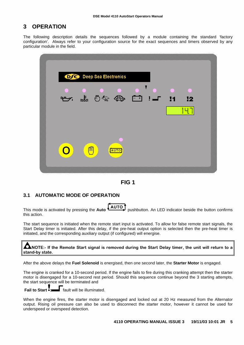
The following description details the sequences followed by a module containing the standard ‘factoryconfiguration’. Always refer to your configuration source for the exact sequences and timers observed by anyparticular module in the field.
FIG 1
3.1 AUTOMATIC MODE OF OPERATION
This mode is activated by pressing the Auto pushbutton. An LED indicator beside the button confirmsthis action.
The start sequence is initiated when the remote start input is activated. To allow for false remote start signals, theStart Delay timer is initiated. After this delay, if the pre-heat output option is selected then the pre-heat timer isinitiated, and the corresponding auxiliary output (if configured) will energise.
NOTE:- If the Remote Start signal is removed during the Start Delay timer, the unit will return to astand-by state.
After the above delays the Fuel Solenoid is energised, then one second later, the Starter Motor is engaged.
The engine is cranked for a 10-second period. If the engine fails to fire during this cranking attempt then the startermotor is disengaged for a 10-second rest period. Should this sequence continue beyond the 3 starting attempts,the start sequence will be terminated and
Fail to Start fault will be illuminated.
When the engine fires, the starter motor is disengaged and locked out at 20 Hz measured from the Alternatoroutput. Rising oil pressure can also be used to disconnect the starter motor, however it cannot be used forunderspeed or overspeed detection.
DSE Model 4110 AutoStart Operators Manual
4110 OPERATING MANUAL ISSUE 3 19/11/03 10:01 JR6
After the starter motor has disengaged, the Safety On timer is activated, allowing Oil Pressure, High EngineTemperature, Under-speed, Charge Fail and any delayed Auxiliary fault inputs to stabilise without triggering thefault.
Once the engine is running, the Warm Up timer, if selected, is initiated, allowing the engine to stabilise before itcan be loaded.
Once the Warm Up timer has expired, the output Load Transfer is activated if it has been configured.
On removal of the Remote Start signal the Stop Delay timer is initiated. After which the Load Transfer output (ifconfigured) is deactivated, and the Cool Down Period is initiated. After the Cool Down Period has elapsed, theFuel Solenoid is de-energised, bringing the generator to a stop.
NOTE:- The safety on time (used for delayed alarms) is pre set to 12 seconds and can not bechanged.
3.2 MANUAL OPERATION
To initiate a start sequence in MANUAL, press the pushbutton.
NOTE:- There is no Start Delay in this mode of operation.
If the pre-heat output option is selected this timer is then initiated, and the auxiliary output selected is energised.
After the above delay the Fuel Solenoid is energised, then the Starter Motor is engaged.
The engine is cranked for a 10 second period. If the engine fails to fire during this cranking attempt then the startermotor is disengaged for the 10 second rest period. Should this sequence continue beyond the 3 cranking attempts,
the start sequence will be terminated and Fail to Start fault will be displayed.
When the engine fires, the starter motor is disengaged and locked out at 20 Hz measured from the Alternatoroutput. Rising oil pressure can also be used to disconnect the starter motor, however it cannot be used forunderspeed or overspeed detection.
After the starter motor has disengaged, the Safety On timer is activated, allowing Oil Pressure, High EngineTemperature, Under-speed and any delayed Auxiliary fault inputs to stabilise without triggering the fault.
NOTE:- The safety on time (used for delayed alarms) is pre set to 12 seconds and can not bechanged.
Once the engine is running, the Warm Up timer, if selected, is initiated, allowing the engine to stabilise before itcan be loaded.
The generator will continue to run until the Auto mode is selected.
If Auto mode is selected, and the automatic start not active, then the Remote Stop Delay Timer begins, afterwhich the Fuel Solenoid is de-energised, bringing the generator to a stop.
Selecting STOP (O) de-energises the FUEL SOLENOID, bringing the generator to a stop.
DSE Model 4110 AutoStart Operators Manual
4110 OPERATING MANUAL ISSUE 3 19/11/03 10:01 JR 7
4 PROTECTIONS
The module will indicate that an alarm has occurred by illuminating the relevant LED.
4.1 WARNINGS
Warnings are used to warn the operator of an impending fault
BATTERY CHARGE FAILURE, if the module does not detect a voltage from the warning light terminal on theauxiliary charge alternator, the icon will illuminate. (Either 8 Volts or 16 Volts depending on the configurationof Nominal DC Voltage).
Inputs 1 and 2 can be configured as warnings or shutdowns. The relevant icon will be illuminated when the input isactive
4.2 SHUTDOWNS
Shutdowns are latching and stop the Generator. The alarm must be cleared, and the fault removed to reset themodule. In the event of a shutdown the appropriate icon will be illuminated
NOTE:- The alarm condition must be rectified before a reset will take place. If the alarm conditionremains it will not be possible to reset the unit (The exception to this is the Low Oil Pressure alarm andsimilar ‘delayed alarms’, as the oil pressure will be low with the engine at rest). Any subsequentwarnings or shutdowns that occur will be displayed steady, therefore only the first-up shutdown willappear flashing.
NOTE:- The safety on time (used for delayed alarms) is pre set to 12 seconds and can not bechanged.
FAIL TO START, if the engine does not fire after the pre-set 3 attempts at starting, a shutdown will be initiated.The icon will illuminate.
LOW OIL PRESSURE, if the module detects that the engine oil pressure has fallen below the low oil pressureswitch after the Safety On timer has expired, a shutdown will occur.The icon will illuminate.
HIGH ENGINE TEMPERATURE if the module detects that the engine coolant temperature has exceeded the highengine temperature switch after the Safety On timer has expired, a shutdown will occur.
The icon will illuminate.
OVERSPEED, if the engine speed exceeds the pre-set trip (14% above the nominal frequency) a shutdown isinitiated. Overspeed is not delayed, it is an immediate shutdown.
The icon will illuminate.
NOTE:- During the start-up sequence the overspeed trip level is extended to 24% above the normalfrequency for the duration of the saftey timer to allow an extra trip level margin. This is used to preventnuisance tripping on start-up.
UNDERSPEED, if the engine speed falls below the pre-set trip (20% of the nominal frequency) after the Safety Ontimer has expired, a shutdown is initiated.
The icon will illuminate.
Inputs 1 and 2 can be configured as warnings or shutdowns. The relevant icon will be illuminated when the input isactive
DSE Model 4110 AutoStart Operators Manual
4110 OPERATING MANUAL ISSUE 3 19/11/03 10:01 JR8
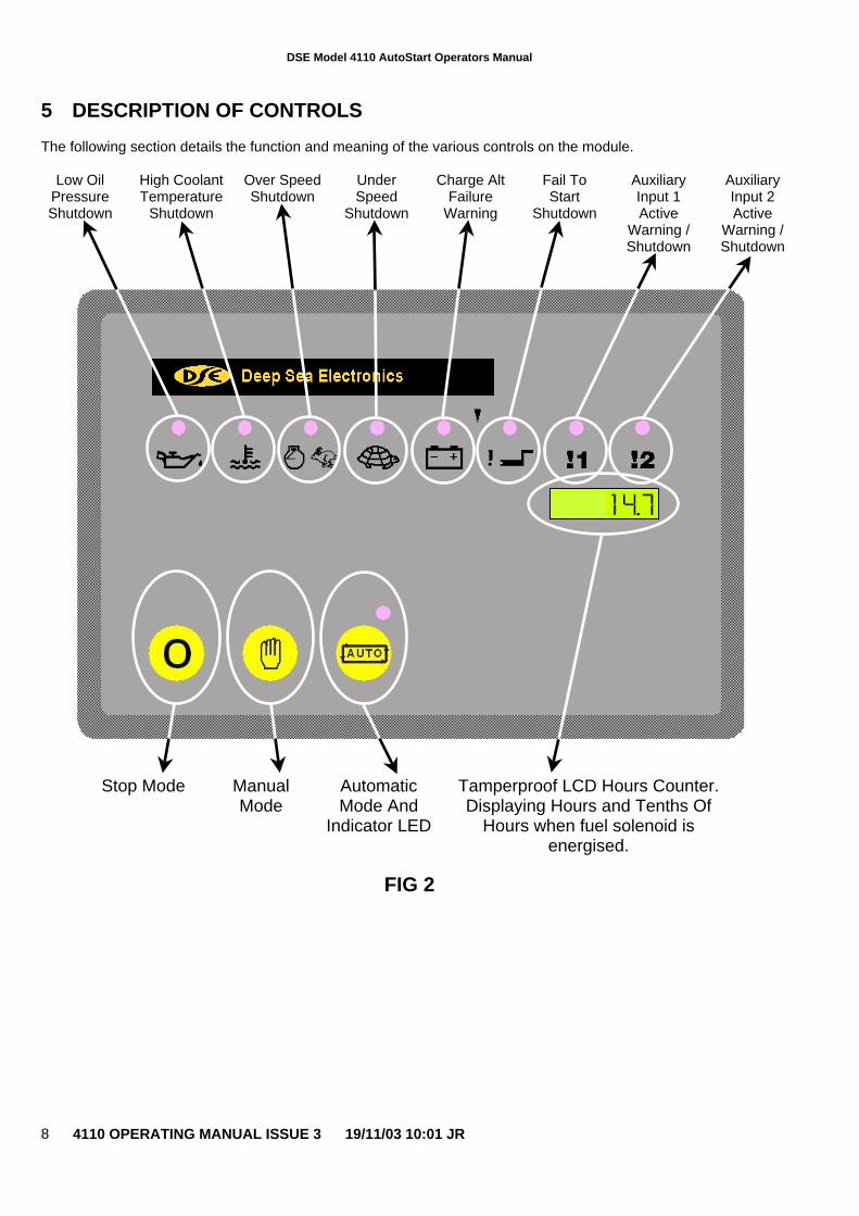
5 DESCRIPTION OF CONTROLS
The following section details the function and meaning of the various controls on the module.
Low OilPressureShutdown
High CoolantTemperature
Shutdown
Over SpeedShutdown
UnderSpeed
Shutdown
Charge AltFailure
Warning
Fail ToStart
Shutdown
AuxiliaryInput 1Active
Warning /Shutdown
AuxiliaryInput 2Active
Warning /Shutdown
Stop Mode ManualMode
AutomaticMode And
Indicator LED
Tamperproof LCD Hours Counter.Displaying Hours and Tenths Of
Hours when fuel solenoid isenergised.
FIG 2
DSE Model 4110 AutoStart Operators Manual
4110 OPERATING MANUAL ISSUE 3 19/11/03 10:01 JR 9
6 FRONT PANEL CONFIGURATION
The DSE 4110 module is fully configurable from the front panel. There is no requirement for a PC / Laptop orsoftware.
6.1 ACCESSING THE FRONT PANEL CONFIGURATION EDITOR
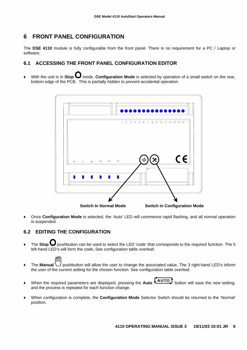
♦ With the unit is in Stop mode, Configuration Mode is selected by operation of a small switch on the rear,bottom edge of the PCB. This is partially hidden to prevent accidental operation.
Switch In Normal Mode Switch in Configuration Mode
♦ Once Configuration Mode is selected, the ‘Auto’ LED will commence rapid flashing, and all normal operationis suspended.
6.2 EDITING THE CONFIGURATION
♦ The Stop pushbutton can be used to select the LED ‘code’ that corresponds to the required function. The 5left-hand LED’s will form the code. See configuration table overleaf.
♦ The Manual pushbutton will allow the user to change the associated value. The 3 right-hand LED’s informthe user of the current setting for the chosen function. See configuration table overleaf.
♦ When the required parameters are displayed, pressing the Auto button will save the new setting,and the process is repeated for each function change.
♦ When configuration is complete, the Configuration Mode Selector Switch should be returned to the ‘Normal’position.
DSE Model 4110 AutoStart Operators Manual
4110 OPERATING MANUAL ISSUE 3 19/11/03 10:01 JR10
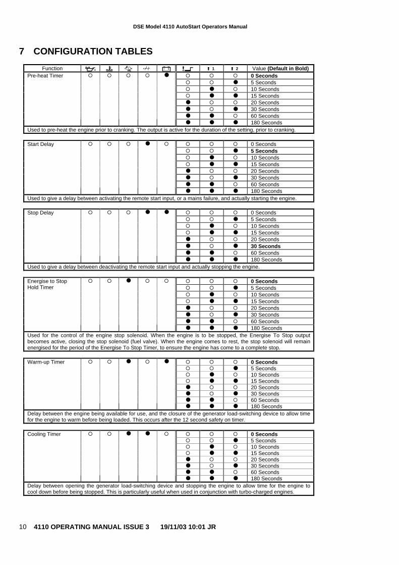
7 CONFIGURATION TABLES
Function !!!! 1 !!!! 2 Value (Default in Bold)� � � 0 Seconds� � ● 5 Seconds� ● � 10 Seconds� ● ● 15 Seconds● � � 20 Seconds● � ● 30 Seconds● ● � 60 Seconds
Pre-heat Timer � � � � ●
● ● ● 180 SecondsUsed to pre-heat the engine prior to cranking. The output is active for the duration of the setting, prior to cranking.
� � � 0 Seconds� � ● 5 Seconds� ● � 10 Seconds� ● ● 15 Seconds● � � 20 Seconds● � ● 30 Seconds● ● � 60 Seconds
Start Delay � � � ● �
● ● ● 180 SecondsUsed to give a delay between activating the remote start input, or a mains failure, and actually starting the engine.
� � � 0 Seconds� � ● 5 Seconds� ● � 10 Seconds� ● ● 15 Seconds● � � 20 Seconds● � ● 30 Seconds● ● � 60 Seconds
Stop Delay � � � ● ●
● ● ● 180 SecondsUsed to give a delay between deactivating the remote start input and actually stopping the engine.
� � � 0 Seconds� � ● 5 Seconds� ● � 10 Seconds� ● ● 15 Seconds● � � 20 Seconds● � ● 30 Seconds● ● � 60 Seconds
Energise to StopHold Timer
� � ● � �
● ● ● 180 SecondsUsed for the control of the engine stop solenoid. When the engine is to be stopped, the Energise To Stop outputbecomes active, closing the stop solenoid (fuel valve). When the engine comes to rest, the stop solenoid will remainenergised for the period of the Energise To Stop Timer, to ensure the engine has come to a complete stop.
� � � 0 Seconds� � ● 5 Seconds� ● � 10 Seconds� ● ● 15 Seconds● � � 20 Seconds● � ● 30 Seconds● ● � 60 Seconds
Warm-up Timer � � ● � ●
● ● ● 180 SecondsDelay between the engine being available for use, and the closure of the generator load-switching device to allow timefor the engine to warm before being loaded. This occurs after the 12 second safety on timer.
� � � 0 Seconds� � ● 5 Seconds� ● � 10 Seconds� ● ● 15 Seconds● � � 20 Seconds● � ● 30 Seconds● ● � 60 Seconds
Cooling Timer � � ● ● �
● ● ● 180 SecondsDelay between opening the generator load-switching device and stopping the engine to allow time for the engine tocool down before being stopped. This is particularly useful when used in conjunction with turbo-charged engines.
DSE Model 4110 AutoStart Operators Manual
4110 OPERATING MANUAL ISSUE 3 19/11/03 10:01 JR 11
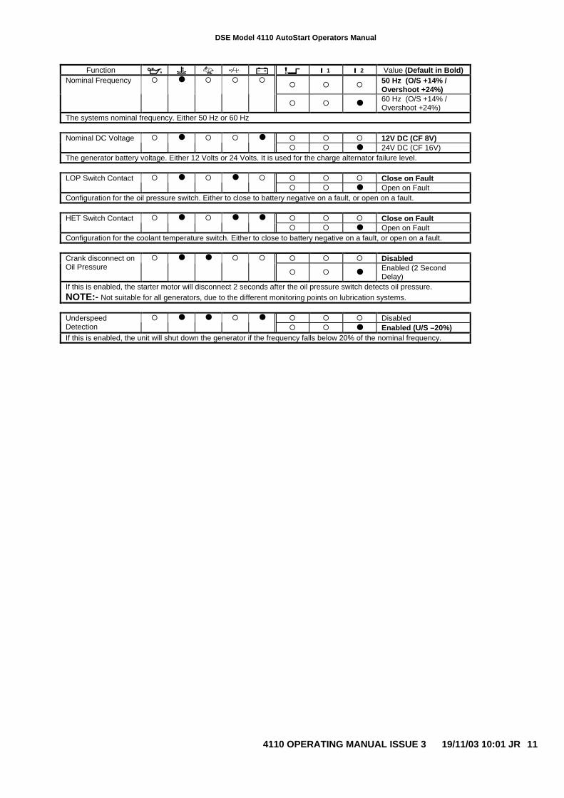
Function !!!! 1 !!!! 2 Value (Default in Bold)
� � �50 Hz (O/S +14% /Overshoot +24%)
Nominal Frequency � ● � � �
� � ●60 Hz (O/S +14% /Overshoot +24%)
The systems nominal frequency. Either 50 Hz or 60 Hz
� � � 12V DC (CF 8V)Nominal DC Voltage � ● � � ●
� � ● 24V DC (CF 16V)The generator battery voltage. Either 12 Volts or 24 Volts. It is used for the charge alternator failure level.
� � � Close on FaultLOP Switch Contact � ● � ● �
� � ● Open on FaultConfiguration for the oil pressure switch. Either to close to battery negative on a fault, or open on a fault.
� � � Close on FaultHET Switch Contact � ● � ● ●
� � ● Open on FaultConfiguration for the coolant temperature switch. Either to close to battery negative on a fault, or open on a fault.
� � � DisabledCrank disconnect onOil Pressure
� ● ● � �
� � ●Enabled (2 SecondDelay)
If this is enabled, the starter motor will disconnect 2 seconds after the oil pressure switch detects oil pressure.NOTE:- Not suitable for all generators, due to the different monitoring points on lubrication systems.
� � � DisabledUnderspeedDetection
� ● ● � ●
� � ● Enabled (U/S –20%)If this is enabled, the unit will shut down the generator if the frequency falls below 20% of the nominal frequency.
DSE Model 4110 AutoStart Operators Manual
4110 OPERATING MANUAL ISSUE 3 19/11/03 10:01 JR12
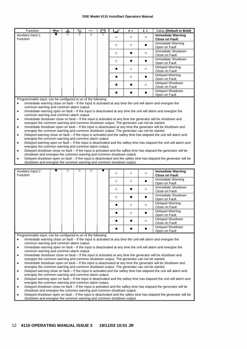
Function !!!! 1 !!!! 2 Value (Default in Bold)
� � �Immediate WarningClose on Fault
� � ●Immediate WarningOpen on Fault
� ● �Immediate ShutdownClose on Fault
� ● ●Immediate ShutdownOpen on Fault
● � �Delayed WarningClose on Fault
● � ●Delayed WarningOpen on Fault
● ● �Delayed ShutdownClose on Fault
Auxiliary Input 1Function
● � � � �
● ● ●Delayed ShutdownOpen on Fault
Programmable input, can be configured to on of the following♦ Immediate warning close on fault – If the input is activated at any time the unit will alarm and energise the
common warning and common alarm output.♦ Immediate warning open on fault – If the input is deactivated at any time the unit will alarm and energise the
common warning and common alarm output.♦ Immediate shutdown close on fault – If the input is activated at any time the generator will be shutdown and
energise the common warning and common shutdown output. The generator can not be started.♦ Immediate shutdown open on fault – If the input is deactivated at any time the generator will be shutdown and
energise the common warning and common shutdown output. The generator can not be started.♦ Delayed warning close on fault – If the input is activated and the saftey time has elapsed the unit will alarm and
energise the common warning and common alarm output.♦ Delayed warning open on fault – If the input is deactivated and the saftey time has elapsed the unit will alarm and
energise the common warning and common alarm output.♦ Delayed shutdown close on fault – If the input is activated and the saftey time has elapsed the generator will be
shutdown and energise the common warning and common shutdown output.♦ Delayed shutdown open on fault – If the input is deactivated and the saftey time has elapsed the generator will be
shutdown and energise the common warning and common shutdown output.
� � �Immediate WarningClose on Fault
� � ●Immediate WarningOpen on Fault
� ● �Immediate ShutdownClose on Fault
� ● ●Immediate ShutdownOpen on Fault
● � �Delayed WarningClose on Fault
● � ●Delayed WarningOpen on Fault
● ● �Delayed ShutdownClose on Fault
Auxiliary Input 2Function
● � � � ●
● ● ●Delayed ShutdownOpen on Fault
Programmable input, can be configured to on of the following♦ Immediate warning close on fault – If the input is activated at any time the unit will alarm and energise the
common warning and common alarm output.♦ Immediate warning open on fault – If the input is deactivated at any time the unit will alarm and energise the
common warning and common alarm output.♦ Immediate shutdown close on fault – If the input is activated at any time the generator will be shutdown and
energise the common warning and common shutdown output. The generator can not be started.♦ Immediate shutdown open on fault – If the input is deactivated at any time the generator will be shutdown and
energise the common warning and common shutdown output. The generator can not be started.♦ Delayed warning close on fault – If the input is activated and the saftey time has elapsed the unit will alarm and
energise the common warning and common alarm output.♦ Delayed warning open on fault – If the input is deactivated and the saftey time has elapsed the unit will alarm and
energise the common warning and common alarm output.♦ Delayed shutdown close on fault – If the input is activated and the saftey time has elapsed the generator will be
shutdown and energise the common warning and common shutdown output.♦ Delayed shutdown open on fault – If the input is deactivated and the saftey time has elapsed the generator will be
shutdown and energise the common warning and common shutdown output.
DSE Model 4110 AutoStart Operators Manual
4110 OPERATING MANUAL ISSUE 3 19/11/03 10:01 JR 13
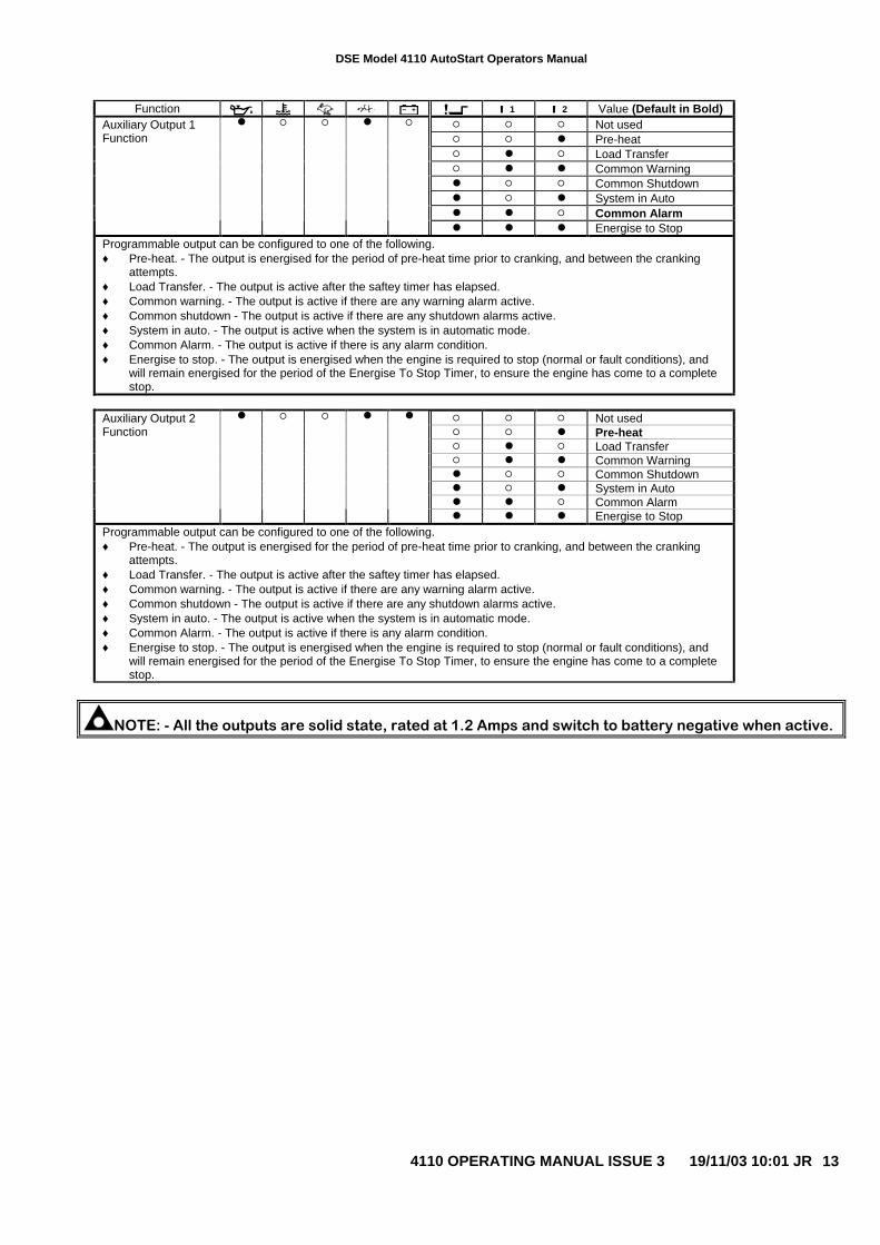
Function !!!! 1 !!!! 2 Value (Default in Bold)� � � Not used� � ● Pre-heat� ● � Load Transfer� ● ● Common Warning● � � Common Shutdown● � ● System in Auto● ● � Common Alarm
Auxiliary Output 1Function
● � � ● �
● ● ● Energise to StopProgrammable output can be configured to one of the following.♦ Pre-heat. - The output is energised for the period of pre-heat time prior to cranking, and between the cranking
attempts.♦ Load Transfer. - The output is active after the saftey timer has elapsed.♦ Common warning. - The output is active if there are any warning alarm active.♦ Common shutdown - The output is active if there are any shutdown alarms active.♦ System in auto. - The output is active when the system is in automatic mode.♦ Common Alarm. - The output is active if there is any alarm condition.♦ Energise to stop. - The output is energised when the engine is required to stop (normal or fault conditions), and
will remain energised for the period of the Energise To Stop Timer, to ensure the engine has come to a completestop.
� � � Not used� � ● Pre-heat� ● � Load Transfer� ● ● Common Warning● � � Common Shutdown● � ● System in Auto● ● � Common Alarm
Auxiliary Output 2Function
● � � ● ●
● ● ● Energise to StopProgrammable output can be configured to one of the following.♦ Pre-heat. - The output is energised for the period of pre-heat time prior to cranking, and between the cranking
attempts.♦ Load Transfer. - The output is active after the saftey timer has elapsed.♦ Common warning. - The output is active if there are any warning alarm active.♦ Common shutdown - The output is active if there are any shutdown alarms active.♦ System in auto. - The output is active when the system is in automatic mode.♦ Common Alarm. - The output is active if there is any alarm condition.♦ Energise to stop. - The output is energised when the engine is required to stop (normal or fault conditions), and
will remain energised for the period of the Energise To Stop Timer, to ensure the engine has come to a completestop.
NOTE: - All the outputs are solid state, rated at 1.2 Amps and switch to battery negative when active.
DSE Model 4110 AutoStart Operators Manual
4110 OPERATING MANUAL ISSUE 3 19/11/03 10:01 JR14
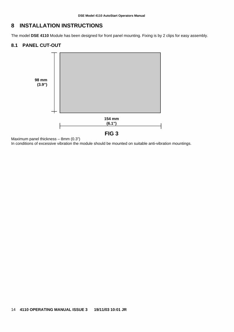
8 INSTALLATION INSTRUCTIONS
The model DSE 4110 Module has been designed for front panel mounting. Fixing is by 2 clips for easy assembly.
8.1 PANEL CUT-OUT
154 mm(6.1”)
FIG 3Maximum panel thickness – 8mm (0.3”)In conditions of excessive vibration the module should be mounted on suitable anti-vibration mountings.
98 mm(3.9”)
DSE Model 4110 AutoStart Operators Manual
4110 OPERATING MANUAL ISSUE 3 19/11/03 10:01 JR 15
8.2 COOLING
The module has been designed to operate over a wide temperature range -30 to +70º C. Allowances should bemade for the temperature rise within the control panel enclosure. Care should be taken NOT to mount possibleheat sources near the module unless adequate ventilation is provided. The relative humidity inside the controlpanel enclosure should not exceed 95%.
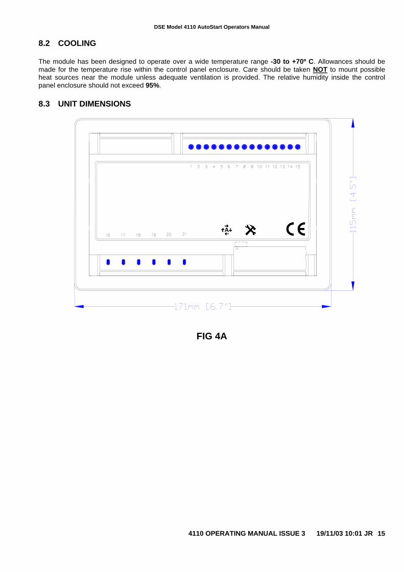
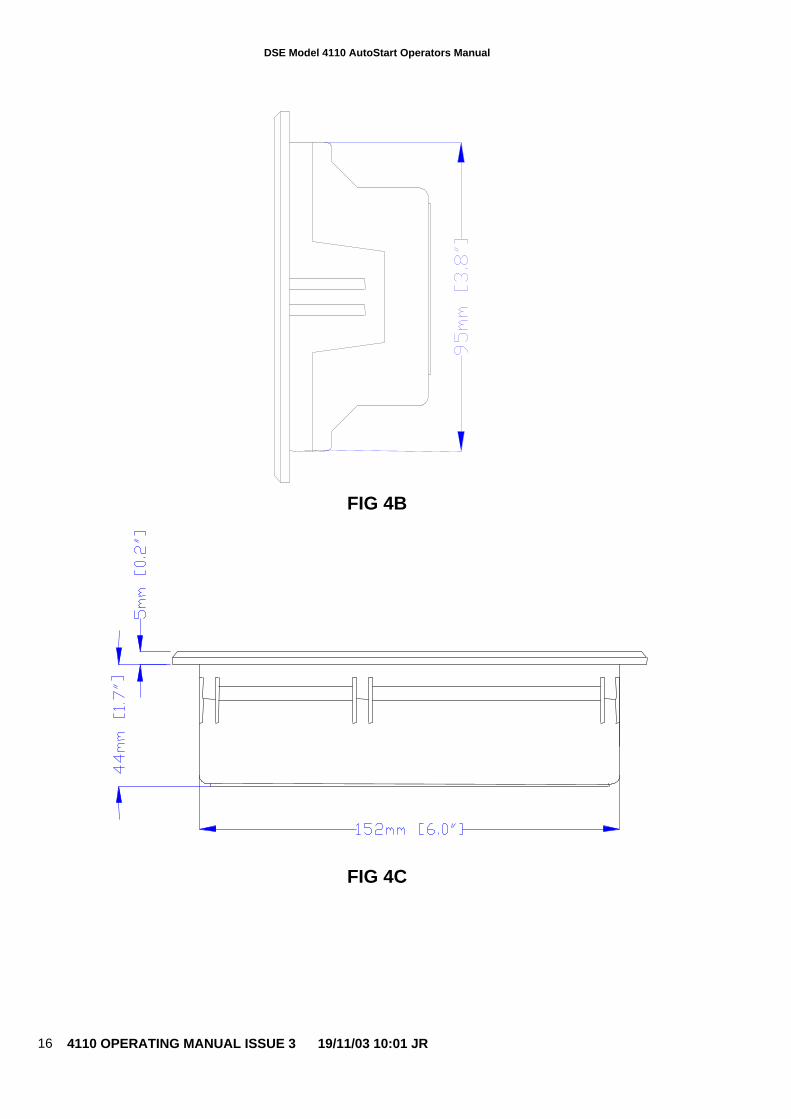
8.3 UNIT DIMENSIONS
FIG 4A
DSE Model 4110 AutoStart Operators Manual
4110 OPERATING MANUAL ISSUE 3 19/11/03 10:01 JR16
FIG 4B
FIG 4C
DSE Model 4110 AutoStart Operators Manual
4110 OPERATING MANUAL ISSUE 3 19/11/03 10:01 JR 17
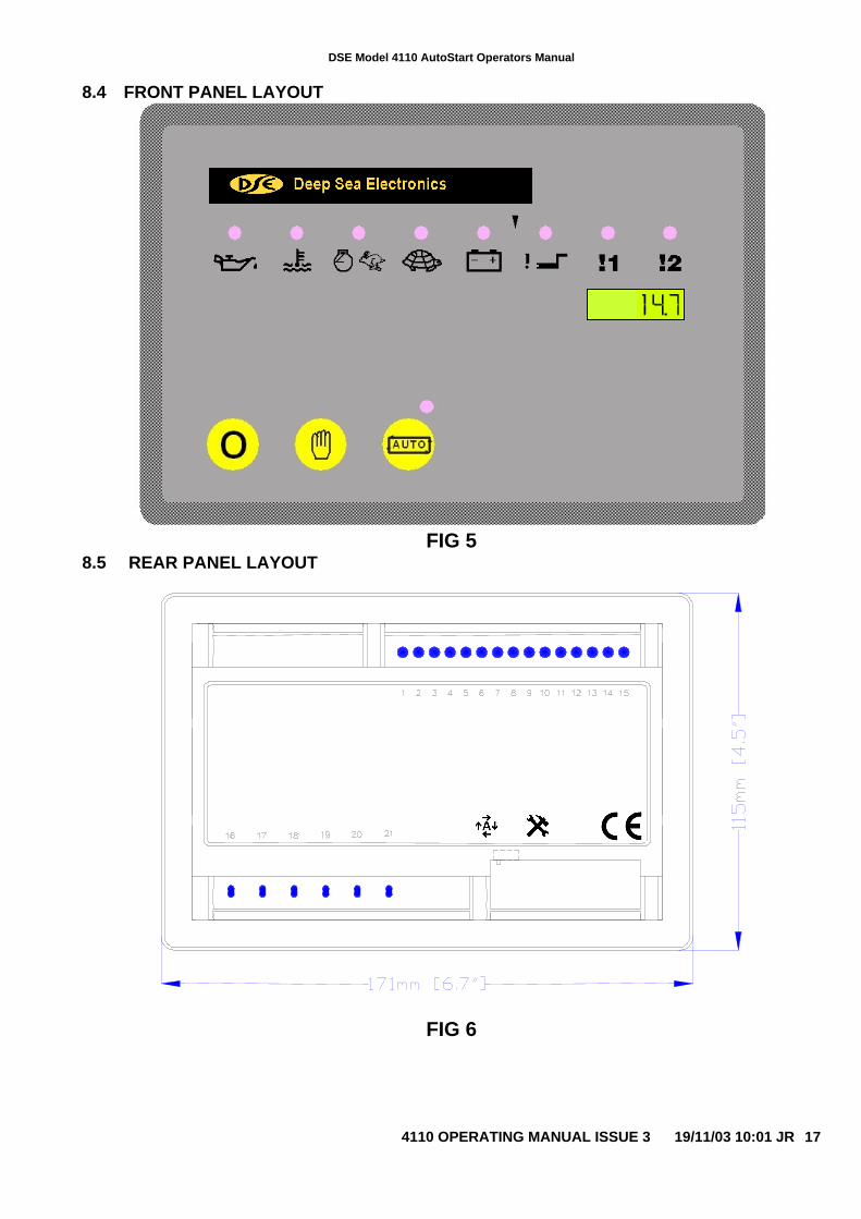
8.4 FRONT PANEL LAYOUT
FIG 58.5 REAR PANEL LAYOUT
FIG 6
DSE Model 4110 AutoStart Operators Manual
4110 OPERATING MANUAL ISSUE 3 19/11/03 10:01 JR18
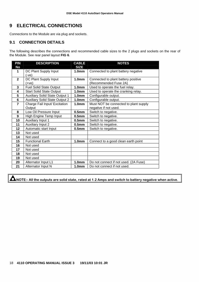
9 ELECTRICAL CONNECTIONS
Connections to the Module are via plug and sockets.
9.1 CONNECTION DETAILS
The following describes the connections and recommended cable sizes to the 2 plugs and sockets on the rear ofthe Module. See rear panel layout FIG 6.
PINNo
DESCRIPTION CABLESIZE
NOTES
1 DC Plant Supply Input(-ve)
1.0mm Connected to plant battery negative
2 DC Plant Supply Input(+ve)
1.0mm Connected to plant battery positive(Recommended Fuse 2A)
3 Fuel Solid State Output 1.0mm Used to operate the fuel relay.4 Start Solid State Output 1.0mm Used to operate the cranking relay.5 Auxiliary Solid State Output 1 1.0mm Configurable output.6 Auxiliary Solid State Output 2 1.0mm Configurable output.7 Charge Fail Input/ Excitation
Output1.0mm Must NOT be connected to plant supply
negative if not used.8 Low Oil Pressure Input 0.5mm Switch to negative.9 High Engine Temp Input 0.5mm Switch to negative.
10 Auxiliary Input 1 0.5mm Switch to negative.11 Auxiliary Input 2 0.5mm Switch to negative.12 Automatic start Input 0.5mm Switch to negative.13 Not used14 Not used15 Functional Earth 1.0mm Connect to a good clean earth point16 Not used17 Not used18 Not used19 Not used20 Alternator Input L1 1.0mm Do not connect if not used. (2A Fuse)21 Alternator Input N 1.0mm Do not connect if not used.
NOTE:- All the outputs are solid state, rated at 1.2 Amps and switch to battery negative when active.
DSE Model 4110 AutoStart Operators Manual
4110 OPERATING MANUAL ISSUE 3 19/11/03 10:01 JR 19
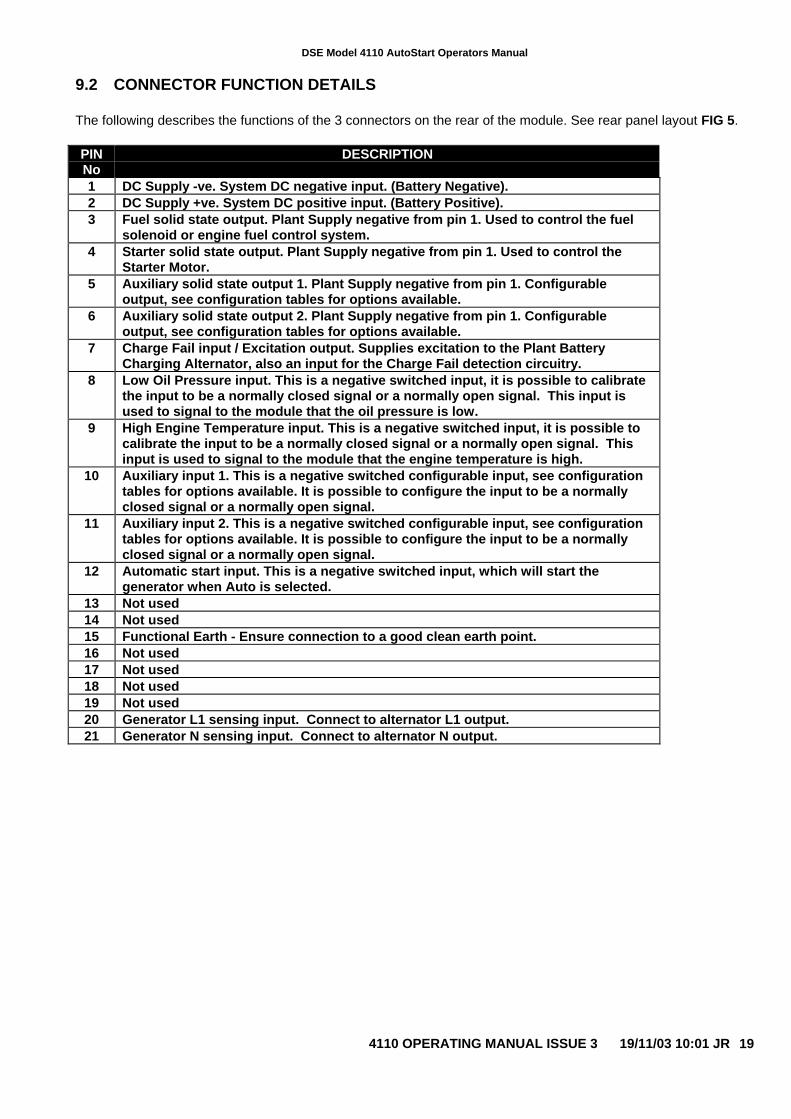
9.2 CONNECTOR FUNCTION DETAILS
The following describes the functions of the 3 connectors on the rear of the module. See rear panel layout FIG 5.
PINNo
DESCRIPTION
1 DC Supply -ve. System DC negative input. (Battery Negative).2 DC Supply +ve. System DC positive input. (Battery Positive).3 Fuel solid state output. Plant Supply negative from pin 1. Used to control the fuel
solenoid or engine fuel control system.4 Starter solid state output. Plant Supply negative from pin 1. Used to control the
Starter Motor.5 Auxiliary solid state output 1. Plant Supply negative from pin 1. Configurable
output, see configuration tables for options available.6 Auxiliary solid state output 2. Plant Supply negative from pin 1. Configurable
output, see configuration tables for options available.7 Charge Fail input / Excitation output. Supplies excitation to the Plant Battery
Charging Alternator, also an input for the Charge Fail detection circuitry.8 Low Oil Pressure input. This is a negative switched input, it is possible to calibrate
the input to be a normally closed signal or a normally open signal. This input isused to signal to the module that the oil pressure is low.
9 High Engine Temperature input. This is a negative switched input, it is possible tocalibrate the input to be a normally closed signal or a normally open signal. Thisinput is used to signal to the module that the engine temperature is high.
10 Auxiliary input 1. This is a negative switched configurable input, see configurationtables for options available. It is possible to configure the input to be a normallyclosed signal or a normally open signal.
11 Auxiliary input 2. This is a negative switched configurable input, see configurationtables for options available. It is possible to configure the input to be a normallyclosed signal or a normally open signal.
12 Automatic start input. This is a negative switched input, which will start thegenerator when Auto is selected.
13 Not used14 Not used15 Functional Earth - Ensure connection to a good clean earth point.16 Not used17 Not used18 Not used19 Not used20 Generator L1 sensing input. Connect to alternator L1 output.21 Generator N sensing input. Connect to alternator N output.
DSE Model 4110 AutoStart Operators Manual
4110 OPERATING MANUAL ISSUE 3 19/11/03 10:01 JR20
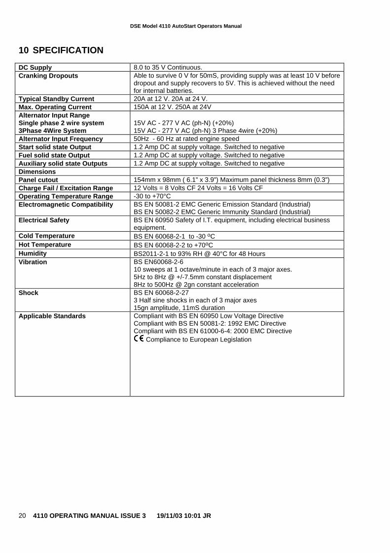
10 SPECIFICATION
DC Supply 8.0 to 35 V Continuous.Cranking Dropouts Able to survive 0 V for 50mS, providing supply was at least 10 V before
dropout and supply recovers to 5V. This is achieved without the needfor internal batteries.
Typical Standby Current 20A at 12 V. 20A at 24 V.Max. Operating Current 150A at 12 V. 250A at 24VAlternator Input RangeSingle phase 2 wire system 15V AC - 277 V AC (ph-N) (+20%)3Phase 4Wire System 15V AC - 277 V AC (ph-N) 3 Phase 4wire (+20%)Alternator Input Frequency 50Hz - 60 Hz at rated engine speedStart solid state Output 1.2 Amp DC at supply voltage. Switched to negativeFuel solid state Output 1.2 Amp DC at supply voltage. Switched to negativeAuxiliary solid state Outputs 1.2 Amp DC at supply voltage. Switched to negativeDimensionsPanel cutout 154mm x 98mm ( 6.1” x 3.9”) Maximum panel thickness 8mm (0.3”)Charge Fail / Excitation Range 12 Volts = 8 Volts CF 24 Volts = 16 Volts CFOperating Temperature Range -30 to +70°CElectromagnetic Compatibility BS EN 50081-2 EMC Generic Emission Standard (Industrial)
BS EN 50082-2 EMC Generic Immunity Standard (Industrial)Electrical Safety BS EN 60950 Safety of I.T. equipment, including electrical business
equipment.Cold Temperature BS EN 60068-2-1 to -30 oCHot Temperature BS EN 60068-2-2 to +70oCHumidity BS2011-2-1 to 93% RH @ 40°C for 48 HoursVibration BS EN60068-2-6
10 sweeps at 1 octave/minute in each of 3 major axes.5Hz to 8Hz @ +/-7.5mm constant displacement8Hz to 500Hz @ 2gn constant acceleration
Shock BS EN 60068-2-273 Half sine shocks in each of 3 major axes15gn amplitude, 11mS duration
Applicable Standards Compliant with BS EN 60950 Low Voltage DirectiveCompliant with BS EN 50081-2: 1992 EMC DirectiveCompliant with BS EN 61000-6-4: 2000 EMC Directive
Compliance to European Legislation
DSE Model 4110 AutoStart Operators Manual
4110 OPERATING MANUAL ISSUE 3 19/11/03 10:01 JR 21
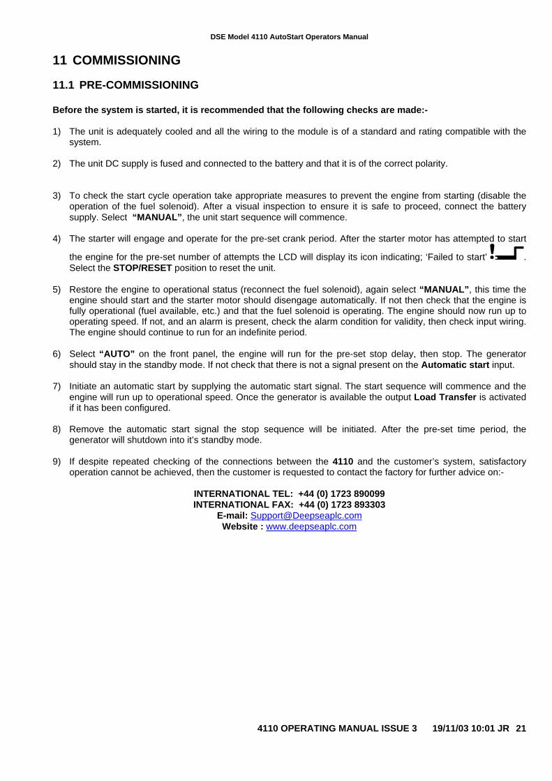
11 COMMISSIONING
11.1 PRE-COMMISSIONING
Before the system is started, it is recommended that the following checks are made:-
1) The unit is adequately cooled and all the wiring to the module is of a standard and rating compatible with thesystem.
2) The unit DC supply is fused and connected to the battery and that it is of the correct polarity.
3) To check the start cycle operation take appropriate measures to prevent the engine from starting (disable theoperation of the fuel solenoid). After a visual inspection to ensure it is safe to proceed, connect the batterysupply. Select “MANUAL”, the unit start sequence will commence.
4) The starter will engage and operate for the pre-set crank period. After the starter motor has attempted to start
the engine for the pre-set number of attempts the LCD will display its icon indicating; ‘Failed to start’ .Select the STOP/RESET position to reset the unit.
5) Restore the engine to operational status (reconnect the fuel solenoid), again select “MANUAL”, this time theengine should start and the starter motor should disengage automatically. If not then check that the engine isfully operational (fuel available, etc.) and that the fuel solenoid is operating. The engine should now run up tooperating speed. If not, and an alarm is present, check the alarm condition for validity, then check input wiring.The engine should continue to run for an indefinite period.
6) Select “AUTO” on the front panel, the engine will run for the pre-set stop delay, then stop. The generatorshould stay in the standby mode. If not check that there is not a signal present on the Automatic start input.
7) Initiate an automatic start by supplying the automatic start signal. The start sequence will commence and theengine will run up to operational speed. Once the generator is available the output Load Transfer is activatedif it has been configured.
8) Remove the automatic start signal the stop sequence will be initiated. After the pre-set time period, thegenerator will shutdown into it’s standby mode.
9) If despite repeated checking of the connections between the 4110 and the customer’s system, satisfactoryoperation cannot be achieved, then the customer is requested to contact the factory for further advice on:-
INTERNATIONAL TEL: +44 (0) 1723 890099INTERNATIONAL FAX: +44 (0) 1723 893303
E-mail: [email protected] : www.deepseaplc.com
DSE Model 4110 AutoStart Operators Manual
4110 OPERATING MANUAL ISSUE 3 19/11/03 10:01 JR22
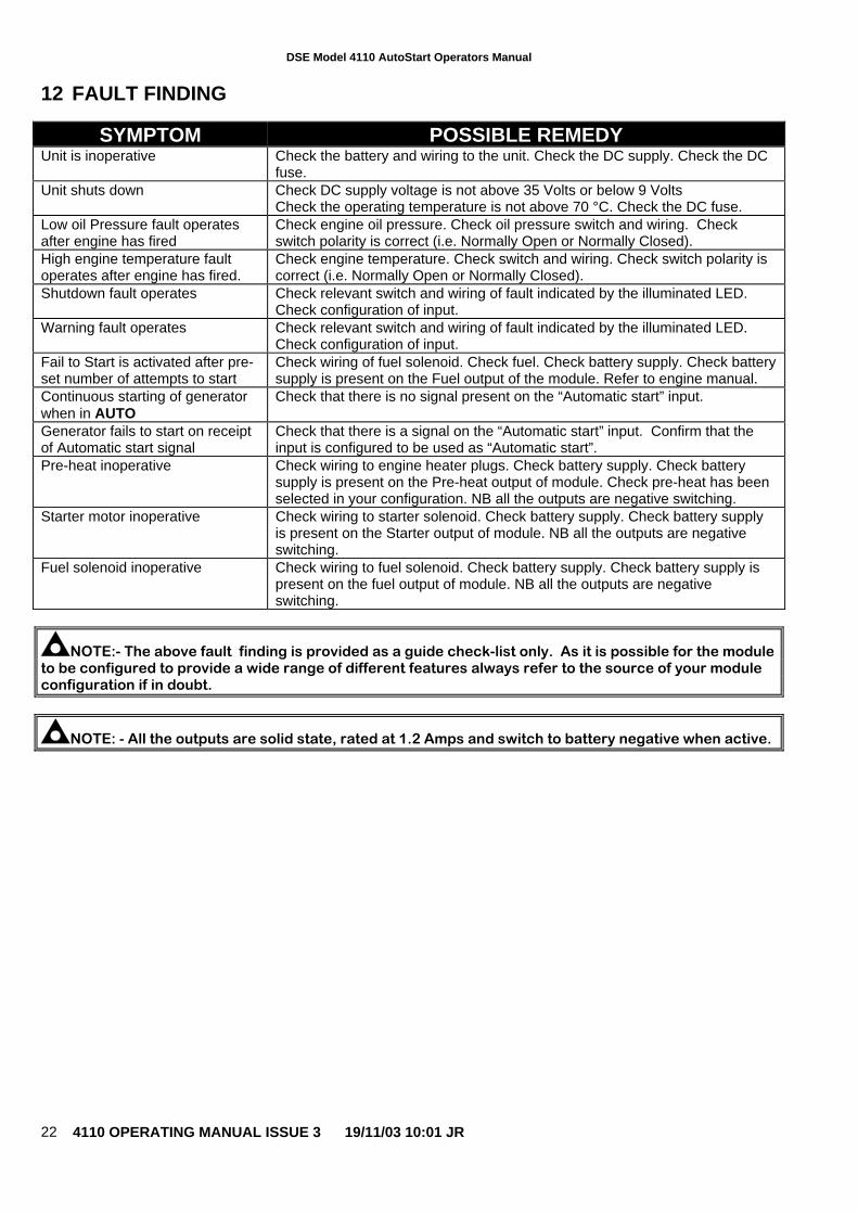
12 FAULT FINDING
SYMPTOM POSSIBLE REMEDYUnit is inoperative Check the battery and wiring to the unit. Check the DC supply. Check the DC
fuse.Unit shuts down Check DC supply voltage is not above 35 Volts or below 9 Volts
Check the operating temperature is not above 70 °C. Check the DC fuse.Low oil Pressure fault operatesafter engine has fired
Check engine oil pressure. Check oil pressure switch and wiring. Checkswitch polarity is correct (i.e. Normally Open or Normally Closed).
High engine temperature faultoperates after engine has fired.
Check engine temperature. Check switch and wiring. Check switch polarity iscorrect (i.e. Normally Open or Normally Closed).
Shutdown fault operates Check relevant switch and wiring of fault indicated by the illuminated LED.Check configuration of input.
Warning fault operates Check relevant switch and wiring of fault indicated by the illuminated LED.Check configuration of input.
Fail to Start is activated after pre-set number of attempts to start
Check wiring of fuel solenoid. Check fuel. Check battery supply. Check batterysupply is present on the Fuel output of the module. Refer to engine manual.
Continuous starting of generatorwhen in AUTO
Check that there is no signal present on the “Automatic start” input.
Generator fails to start on receiptof Automatic start signal
Check that there is a signal on the “Automatic start” input. Confirm that theinput is configured to be used as “Automatic start”.
Pre-heat inoperative Check wiring to engine heater plugs. Check battery supply. Check batterysupply is present on the Pre-heat output of module. Check pre-heat has beenselected in your configuration. NB all the outputs are negative switching.
Starter motor inoperative Check wiring to starter solenoid. Check battery supply. Check battery supplyis present on the Starter output of module. NB all the outputs are negativeswitching.
Fuel solenoid inoperative Check wiring to fuel solenoid. Check battery supply. Check battery supply ispresent on the fuel output of module. NB all the outputs are negativeswitching.
NOTE:- The above fault finding is provided as a guide check-list only. As it is possible for the moduleto be configured to provide a wide range of different features always refer to the source of your moduleconfiguration if in doubt.
NOTE: - All the outputs are solid state, rated at 1.2 Amps and switch to battery negative when active.

DSE Model 4110 AutoStart Operators Manual
4110 OPERATING MANUAL ISSUE 3 19/11/03 10:01 JR 23
13 TYPICAL WIRING DIAGRAM
DSE Model 4110 AutoStart Operators Manual
4110 OPERATING MANUAL ISSUE 3 19/11/03 10:01 JR24
14 APPENDIX
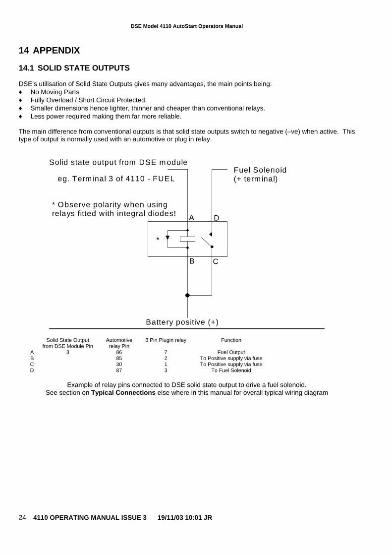
14.1 SOLID STATE OUTPUTS
DSE’s utilisation of Solid State Outputs gives many advantages, the main points being:♦ No Moving Parts♦ Fully Overload / Short Circuit Protected.♦ Smaller dimensions hence lighter, thinner and cheaper than conventional relays.♦ Less power required making them far more reliable.
The main difference from conventional outputs is that solid state outputs switch to negative (–ve) when active. Thistype of output is normally used with an automotive or plug in relay.
Battery positive (+)
Solid state output from DSE module
eg. Term inal 3 of 4110 - FUELFuel Solenoid(+ term inal)
* Observe polarity when usingrelays fitted with integral diodes!
*
A D
B C
Solid State Outputfrom DSE Module Pin
Automotiverelay Pin
8 Pin Plugin relay Function
3 86 7 Fuel Output85 2 To Positive supply via fuse30 1 To Positive supply via fuse
ABCD 87 3 To Fuel Solenoid
Example of relay pins connected to DSE solid state output to drive a fuel solenoid.See section on Typical Connections else where in this manual for overall typical wiring diagram
DSE Model 4110 AutoStart Operators Manual
4110 OPERATING MANUAL ISSUE 3 19/11/03 10:01 JR 25
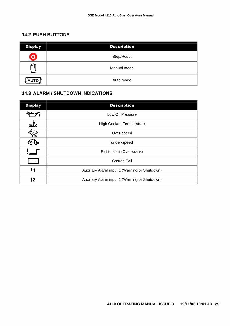
14.2 PUSH BUTTONS
Display Description
Stop/Reset
Manual mode
Auto mode
14.3 ALARM / SHUTDOWN INDICATIONS
Display Description
Low Oil Pressure
High Coolant Temperature
Over-speed
under-speed
Fail to start (Over-crank)
Charge Fail
!!!!1 Auxiliary Alarm input 1 (Warning or Shutdown)
!!!!2 Auxiliary Alarm input 2 (Warning or Shutdown)

DSE Model 4110 AutoStart Operators Manual
4110 OPERATING MANUAL ISSUE 3 19/11/03 10:01 JR26
<<< THIS PAGE INTENTIONALLY BLANK >>><<< THIS PAGE INTENTIONALLY BLANK >>><<< THIS PAGE INTENTIONALLY BLANK >>><<< THIS PAGE INTENTIONALLY BLANK >>>