Embed Size (px)
Citation preview
Author's personal copy
Investigation of effect of polyurea on response of steel platesto impulsive loads in direct pressure-pulse experiments
M.R. Amini, J. Isaacs, S. Nemat-Nasser *
Center of Excellence for Advanced Materials, Department of Mechanical and Aerospace Engineering, University of California, San Diego,La Jolla, CA 92093-0416, USA
a r t i c l e i n f o
Article history:Received 25 September 2009
Keywords:Direct ballisticSteel-polyurea bilayerFracture resistance
a b s t r a c t
We summarize the results of the response of monolithic steel plates and steel-polyureabilayer plates to impulsive blast loads produced in direct pressure-pulse experiments,focusing on the deformation and failure modes of the plates. In these experiments, animpulsive pressure pulse is applied to a steel plate through water or soft polyurethane thatsimulates shock loading with a peak pressure of �80 MPa and duration of �50 ls, followedby a cavitation period and a post-cavitation peak pressure of �40 MPa and �400 ls dura-tion. The pressure pulse is produced by a projectile that impacts either a confined water- orsoft polyurethane-layer which in turn transmits the pulse and loads the sample supportedby a hollow steel cylinder. Using high-speed photography, the deformation and fracturingof some of the plates are also captured. In addition, the total force acting on the steel plateis measured as a function of time in several selected cases.
The experimental results suggest that the presence of polyurea on the back face (oppositeto the load-receiving side) of the steel plates can enhance the energy absorption of theplates and help to mitigate their failure. On the other hand, when polyurea is placed onthe front face (load-receiving side), it will magnify the initial shock effect and promote fail-ure. These experimental results are paralleled by numerical simulations of the entireexperiment, employing physics-based models for the DH-36 steel and polyurea (Aminiet al., 2010b.
� 2009 Published by Elsevier Ltd.
1. Introduction
Enhancing the energy absorption and improving the dy-namic fracture resistance of steel plate structures havebeen the focus of many studies for decades. Coating thesteel plates with a polyurea layer has proven to signifi-cantly affect the survivability of such structures under highintensity impulsive loads, including those encountered inblast events. Polyurea is an inexpensive, fire-resistant,light-weight, soft, and abrasion-resistant retrofit for steelplates. It can be easily applied through spray-cast tech-niques to large steel panels (e.g., ship hulls).
There are only a few published experimental studies onthe effect of polyurea on the blast resistance of steel plates,as controlled laboratory-scale blast experiments are diffi-cult to perform. In a recent study, Amini et al. (2010a) em-ployed a reverse impact experimental technique toinvestigate the effect of polyurea on the impulsive re-sponse of steel plates. Using direct penetration tests, Mockand Balizer (2005) report that a polyurea layer cast ontothe back face of a steel plate can change the response ofthe plate from full penetration of the impacting projectileto its full arrest.
In the present experimental study, we have examinedthe deformation and failure modes of steel (DH-36) andsteel-polyurea bilayer plates to impulsive pressure loads,using a direct pressure-pulse technique. In these experi-ments, an impulsive pressure pulse is applied to a steel
0167-6636/$ - see front matter � 2009 Published by Elsevier Ltd.doi:10.1016/j.mechmat.2009.09.008
* Corresponding author. Address: Mechanical and Aerospace Engineer-ing, University of California at San Diego, 4209 Engineering Building 1,9500 Gilman Drive, La Jolla, CA 92093-0416, USA. Tel.: +1 858 534 4914.
E-mail address: [email protected] (S. Nemat-Nasser).
Mechanics of Materials 42 (2010) 628–639
Contents lists available at ScienceDirect
Mechanics of Materials
journal homepage: www.elsevier .com/locate /mechmat
Author's personal copy
plate through water or soft polyurethane that simulatesshock loading with a peak pressure of about 80 MPa andduration of about 50 ls, followed by a cavitation periodand a post-cavitation peak pressure of about 40 MPa and400 ls duration. This experimental method allows us toassess the shock resistance, dynamic response, and fractur-ing of monolithic steel and steel-polyurea bilayer plates.High-speed photography is also employed to investigatethe time variation of the deformation and the subsequentfailure of some of the plates.
2. Materials and samples
2.1. Materials
2.1.1. DH-36. SteelThe plates are made out of DH-36 steel sheets. DH-36
steel is a high-strength steel used in naval applications.The stress–strain behavior of this material has been sys-tematically studied by Nemat-Nasser and Guo (2003) overa wide range of strain rates and temperatures. Nemat-Nas-ser and Guo also developed a physics-based (PB) constitu-tive model for this material. It is known that themechanical properties of steel may vary depending onthe rolling direction and other production details. In orderto compare the high strain rate properties of the presentDH-36 with those reported in Nemat-Nasser and Guo(2003), a set of Hopkinson bar experiments are performedat various strain rates. It is observed that the plate used inthe current study has approximately 10% higher flow stresscompared with the one reported in Nemat-Nasser and Guo(2003). Considering this difference, minor changes are ap-plied to the PB model presented by Nemat-Nasser and Guo.This modified PB model is incorporated into the commer-cially available finite-element code, LS-DYNA, and used topredict the experimental results (Amini et al., 2010a).
2.1.2. PolyureaThe bilayer plates are comprised of polyurea and DH-36
steel. Polyurea’s physical and mechanical properties varywith its composition. The polyurea used in this study isprepared at CEAM/UCSD, using Isonate 2143 (The DowChemical Company, 2001) and Versalink P1000 (Air Prod-ucts and Chemicals, Inc., 2003). The viscoelastic propertiesof this polyurea have been experimentally studied by Ami-rkhizi et al. (2006) over a wide range of temperatures andstrain rates, including its pressure sensitivity. Based on thisstudy (Amirkhizi et al., 2006), a pressure, temperature, and
strain-rate dependent model has been developed by theseauthors and implemented into LS-DYNA.
2.2. Monolithic DH-36 steel plate samples
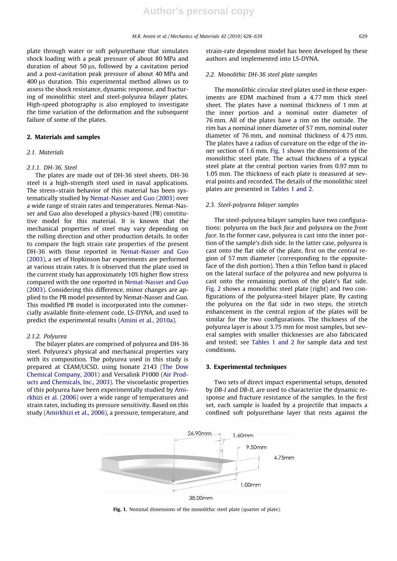
The monolithic circular steel plates used in these exper-iments are EDM machined from a 4.77 mm thick steelsheet. The plates have a nominal thickness of 1 mm atthe inner portion and a nominal outer diameter of76 mm. All of the plates have a rim on the outside. Therim has a nominal inner diameter of 57 mm, nominal outerdiameter of 76 mm, and nominal thickness of 4.75 mm.The plates have a radius of curvature on the edge of the in-ner section of 1.6 mm. Fig. 1 shows the dimensions of themonolithic steel plate. The actual thickness of a typicalsteel plate at the central portion varies from 0.97 mm to1.05 mm. The thickness of each plate is measured at sev-eral points and recorded. The details of the monolithic steelplates are presented in Tables 1 and 2.
2.3. Steel-polyurea bilayer samples
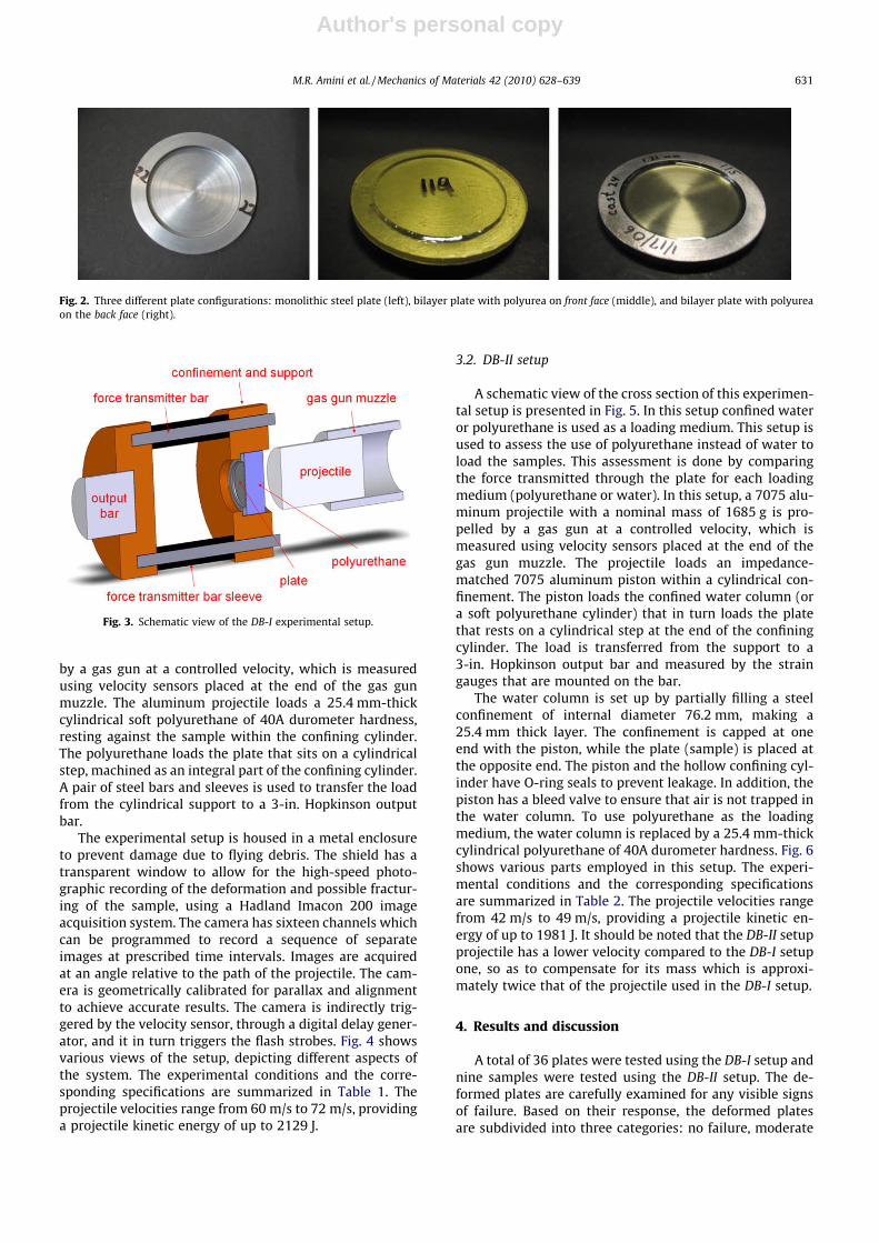
The steel-polyurea bilayer samples have two configura-tions: polyurea on the back face and polyurea on the frontface. In the former case, polyurea is cast into the inner por-tion of the sample’s dish side. In the latter case, polyurea iscast onto the flat side of the plate, first on the central re-gion of 57 mm diameter (corresponding to the opposite-face of the dish portion). Then a thin Teflon band is placedon the lateral surface of the polyurea and new polyurea iscast onto the remaining portion of the plate’s flat side.Fig. 2 shows a monolithic steel plate (right) and two con-figurations of the polyurea-steel bilayer plate. By castingthe polyurea on the flat side in two steps, the stretchenhancement in the central region of the plates will besimilar for the two configurations. The thickness of thepolyurea layer is about 3.75 mm for most samples, but sev-eral samples with smaller thicknesses are also fabricatedand tested; see Tables 1 and 2 for sample data and testconditions.
3. Experimental techniques
Two sets of direct impact experimental setups, denotedby DB-I and DB-II, are used to characterize the dynamic re-sponse and fracture resistance of the samples. In the firstset, each sample is loaded by a projectile that impacts aconfined soft polyurethane layer that rests against the
Fig. 1. Nominal dimensions of the monolithic steel plate (quarter of plate).
M.R. Amini et al. / Mechanics of Materials 42 (2010) 628–639 629
Author's personal copy
sample, while, in the second set, a layer of confined wateris used in some of the tests and soft polyurethane in others.These techniques are developed at UCSD’s Center of Excel-lence for Advanced Materials’ gas gun facilities laboratory.They are discussed in what follows.
3.1. DB-I setup
A schematic view of the cross section of this experimen-tal setup is presented in Fig. 3. In this setup, a 7075 alumi-num projectile with a nominal mass of 832 g is propelled
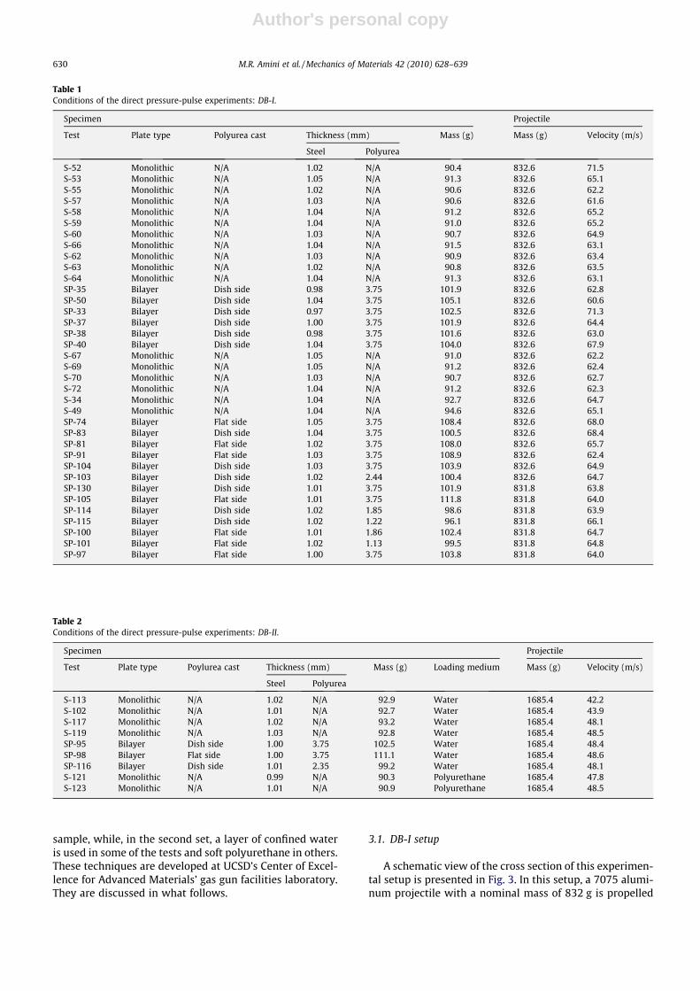
Table 1Conditions of the direct pressure-pulse experiments: DB-I.
Specimen Projectile
Test Plate type Polyurea cast Thickness (mm) Mass (g) Mass (g) Velocity (m/s)
Steel Polyurea
S-52 Monolithic N/A 1.02 N/A 90.4 832.6 71.5S-53 Monolithic N/A 1.05 N/A 91.3 832.6 65.1S-55 Monolithic N/A 1.02 N/A 90.6 832.6 62.2S-57 Monolithic N/A 1.03 N/A 90.6 832.6 61.6S-58 Monolithic N/A 1.04 N/A 91.2 832.6 65.2S-59 Monolithic N/A 1.04 N/A 91.0 832.6 65.2S-60 Monolithic N/A 1.03 N/A 90.7 832.6 64.9S-66 Monolithic N/A 1.04 N/A 91.5 832.6 63.1S-62 Monolithic N/A 1.03 N/A 90.9 832.6 63.4S-63 Monolithic N/A 1.02 N/A 90.8 832.6 63.5S-64 Monolithic N/A 1.04 N/A 91.3 832.6 63.1SP-35 Bilayer Dish side 0.98 3.75 101.9 832.6 62.8SP-50 Bilayer Dish side 1.04 3.75 105.1 832.6 60.6SP-33 Bilayer Dish side 0.97 3.75 102.5 832.6 71.3SP-37 Bilayer Dish side 1.00 3.75 101.9 832.6 64.4SP-38 Bilayer Dish side 0.98 3.75 101.6 832.6 63.0SP-40 Bilayer Dish side 1.04 3.75 104.0 832.6 67.9S-67 Monolithic N/A 1.05 N/A 91.0 832.6 62.2S-69 Monolithic N/A 1.05 N/A 91.2 832.6 62.4S-70 Monolithic N/A 1.03 N/A 90.7 832.6 62.7S-72 Monolithic N/A 1.04 N/A 91.2 832.6 62.3S-34 Monolithic N/A 1.04 N/A 92.7 832.6 64.7S-49 Monolithic N/A 1.04 N/A 94.6 832.6 65.1SP-74 Bilayer Flat side 1.05 3.75 108.4 832.6 68.0SP-83 Bilayer Dish side 1.04 3.75 100.5 832.6 68.4SP-81 Bilayer Flat side 1.02 3.75 108.0 832.6 65.7SP-91 Bilayer Flat side 1.03 3.75 108.9 832.6 62.4SP-104 Bilayer Dish side 1.03 3.75 103.9 832.6 64.9SP-103 Bilayer Dish side 1.02 2.44 100.4 832.6 64.7SP-130 Bilayer Dish side 1.01 3.75 101.9 831.8 63.8SP-105 Bilayer Flat side 1.01 3.75 111.8 831.8 64.0SP-114 Bilayer Dish side 1.02 1.85 98.6 831.8 63.9SP-115 Bilayer Dish side 1.02 1.22 96.1 831.8 66.1SP-100 Bilayer Flat side 1.01 1.86 102.4 831.8 64.7SP-101 Bilayer Flat side 1.02 1.13 99.5 831.8 64.8SP-97 Bilayer Flat side 1.00 3.75 103.8 831.8 64.0
Table 2Conditions of the direct pressure-pulse experiments: DB-II.
Specimen Projectile
Test Plate type Poylurea cast Thickness (mm) Mass (g) Loading medium Mass (g) Velocity (m/s)
Steel Polyurea
S-113 Monolithic N/A 1.02 N/A 92.9 Water 1685.4 42.2S-102 Monolithic N/A 1.01 N/A 92.7 Water 1685.4 43.9S-117 Monolithic N/A 1.02 N/A 93.2 Water 1685.4 48.1S-119 Monolithic N/A 1.03 N/A 92.8 Water 1685.4 48.5SP-95 Bilayer Dish side 1.00 3.75 102.5 Water 1685.4 48.4SP-98 Bilayer Flat side 1.00 3.75 111.1 Water 1685.4 48.6SP-116 Bilayer Dish side 1.01 2.35 99.2 Water 1685.4 48.1S-121 Monolithic N/A 0.99 N/A 90.3 Polyurethane 1685.4 47.8S-123 Monolithic N/A 1.01 N/A 90.9 Polyurethane 1685.4 48.5
630 M.R. Amini et al. / Mechanics of Materials 42 (2010) 628–639
Author's personal copy
by a gas gun at a controlled velocity, which is measuredusing velocity sensors placed at the end of the gas gunmuzzle. The aluminum projectile loads a 25.4 mm-thickcylindrical soft polyurethane of 40A durometer hardness,resting against the sample within the confining cylinder.The polyurethane loads the plate that sits on a cylindricalstep, machined as an integral part of the confining cylinder.A pair of steel bars and sleeves is used to transfer the loadfrom the cylindrical support to a 3-in. Hopkinson outputbar.
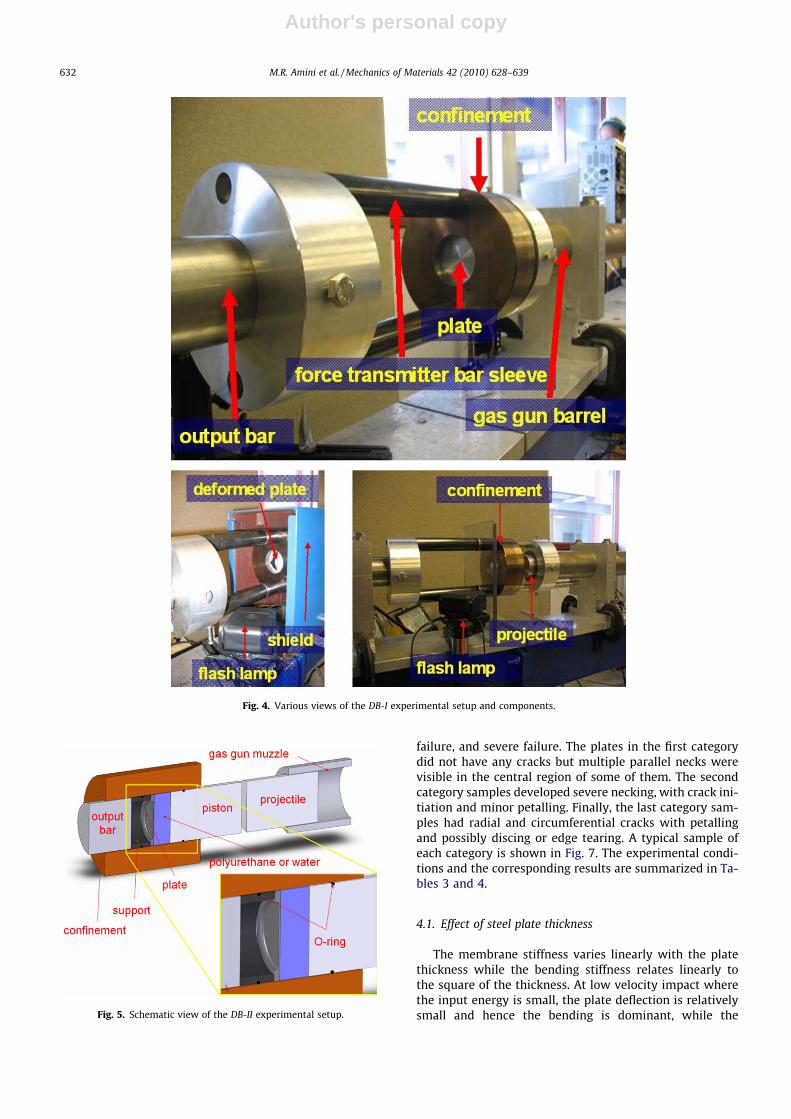
The experimental setup is housed in a metal enclosureto prevent damage due to flying debris. The shield has atransparent window to allow for the high-speed photo-graphic recording of the deformation and possible fractur-ing of the sample, using a Hadland Imacon 200 imageacquisition system. The camera has sixteen channels whichcan be programmed to record a sequence of separateimages at prescribed time intervals. Images are acquiredat an angle relative to the path of the projectile. The cam-era is geometrically calibrated for parallax and alignmentto achieve accurate results. The camera is indirectly trig-gered by the velocity sensor, through a digital delay gener-ator, and it in turn triggers the flash strobes. Fig. 4 showsvarious views of the setup, depicting different aspects ofthe system. The experimental conditions and the corre-sponding specifications are summarized in Table 1. Theprojectile velocities range from 60 m/s to 72 m/s, providinga projectile kinetic energy of up to 2129 J.
3.2. DB-II setup
A schematic view of the cross section of this experimen-tal setup is presented in Fig. 5. In this setup confined wateror polyurethane is used as a loading medium. This setup isused to assess the use of polyurethane instead of water toload the samples. This assessment is done by comparingthe force transmitted through the plate for each loadingmedium (polyurethane or water). In this setup, a 7075 alu-minum projectile with a nominal mass of 1685 g is pro-pelled by a gas gun at a controlled velocity, which ismeasured using velocity sensors placed at the end of thegas gun muzzle. The projectile loads an impedance-matched 7075 aluminum piston within a cylindrical con-finement. The piston loads the confined water column (ora soft polyurethane cylinder) that in turn loads the platethat rests on a cylindrical step at the end of the confiningcylinder. The load is transferred from the support to a3-in. Hopkinson output bar and measured by the straingauges that are mounted on the bar.
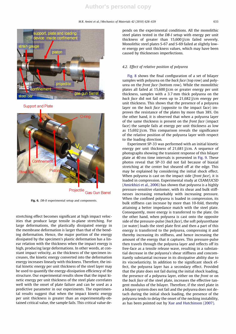
The water column is set up by partially filling a steelconfinement of internal diameter 76.2 mm, making a25.4 mm thick layer. The confinement is capped at oneend with the piston, while the plate (sample) is placed atthe opposite end. The piston and the hollow confining cyl-inder have O-ring seals to prevent leakage. In addition, thepiston has a bleed valve to ensure that air is not trapped inthe water column. To use polyurethane as the loadingmedium, the water column is replaced by a 25.4 mm-thickcylindrical polyurethane of 40A durometer hardness. Fig. 6shows various parts employed in this setup. The experi-mental conditions and the corresponding specificationsare summarized in Table 2. The projectile velocities rangefrom 42 m/s to 49 m/s, providing a projectile kinetic en-ergy of up to 1981 J. It should be noted that the DB-II setupprojectile has a lower velocity compared to the DB-I setupone, so as to compensate for its mass which is approxi-mately twice that of the projectile used in the DB-I setup.
4. Results and discussion
A total of 36 plates were tested using the DB-I setup andnine samples were tested using the DB-II setup. The de-formed plates are carefully examined for any visible signsof failure. Based on their response, the deformed platesare subdivided into three categories: no failure, moderate
Fig. 2. Three different plate configurations: monolithic steel plate (left), bilayer plate with polyurea on front face (middle), and bilayer plate with polyureaon the back face (right).
Fig. 3. Schematic view of the DB-I experimental setup.
M.R. Amini et al. / Mechanics of Materials 42 (2010) 628–639 631
Author's personal copy
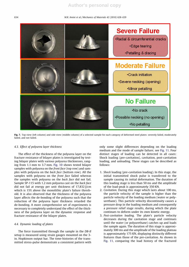
failure, and severe failure. The plates in the first categorydid not have any cracks but multiple parallel necks werevisible in the central region of some of them. The secondcategory samples developed severe necking, with crack ini-tiation and minor petalling. Finally, the last category sam-ples had radial and circumferential cracks with petallingand possibly discing or edge tearing. A typical sample ofeach category is shown in Fig. 7. The experimental condi-tions and the corresponding results are summarized in Ta-bles 3 and 4.
4.1. Effect of steel plate thickness
The membrane stiffness varies linearly with the platethickness while the bending stiffness relates linearly tothe square of the thickness. At low velocity impact wherethe input energy is small, the plate deflection is relativelysmall and hence the bending is dominant, while the
Fig. 4. Various views of the DB-I experimental setup and components.
Fig. 5. Schematic view of the DB-II experimental setup.
632 M.R. Amini et al. / Mechanics of Materials 42 (2010) 628–639
Author's personal copy
stretching effect becomes significant at high impact veloc-ities that produce large tensile in-plane stretching. Forlarge deformations, the plastically dissipated energy inthe membrane deformation is larger than that of the bend-ing deformation. Hence, the major portion of the energydissipated by the specimen’s plastic deformation has a lin-ear relation with the thickness when the impact energy ishigh, producing large deformations. In other words, at con-stant impact velocity, as the thickness of the specimen in-creases, the kinetic energy converted into the deformationenergy increases linearly with thickness. Therefore, the ini-tial kinetic energy per unit thickness of the steel layer maybe used to quantify the energy-dissipation efficiency of thestructure. Our experimental results show that the input ki-netic energy per unit thickness of the steel plate correlateswell with the onset of plate failure and can be used as apredictive parameter in our experiments. The experimen-tal results suggest that when the impact kinetic energyper unit thickness is greater than an experimentally-ob-tained critical value, the sample fails. This critical value de-
pends on the experimental conditions. All the monolithicsteel plates tested in the DB-I setup with energy per unitthickness of greater than 15,600 J/cm failed severely.Monolithic steel plates S-67 and S-69 failed at slightly low-er energy per unit thickness values, which may have beencaused by thicknesses imperfections.
4.2. Effect of relative position of polyurea
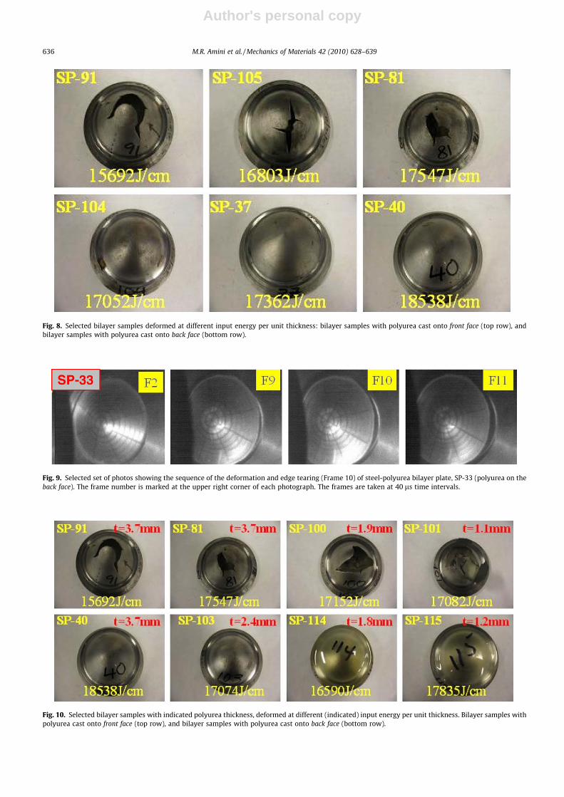
Fig. 8 shows the final configuration of a set of bilayersamples with polyurea on the back face (top row) and poly-urea on the front face (bottom row). While the monolithicplates all failed at 15,600 J/cm or greater energy per unitthickness, samples with a 3.7 mm thick polyurea on theback face did not fail even up to 21,682 J/cm energy perunit thickness. This shows that the presence of a polyurealayer on the back face (opposite to the impact face) im-proves the resistance of the plates by more than 38%. Onthe other hand, it is observed that when a polyurea layerof the same thickness is present on the front face (impactface) the sample fails at energy per unit thickness as lowas 15,692 J/cm. This comparison reveals the significanceof the relative position of the polyurea layer with respectto the loading direction.
Experiment SP-33 was performed with an initial kineticenergy per unit thickness of 21,681 J/cm. A sequence ofphotographs showing the transient response of this bilayerplate at 40 ms time intervals is presented in Fig. 9. Thesephotos reveal that SP-33 did not fail because of biaxialstretching at the center but sheared off at the edge. Thismay be explained by considering the initial shock effect.When polyurea is cast on the impact side (front face), it isloaded in compression. Experimental study at CEAM/UCSD(Amirkhizi et al., 2006) has shown that polyurea is a highlypressure-sensitive elastomer, with its shear and bulk stiff-nesses increasing remarkably with increasing pressure.When the confined polyurea is loaded in compression, itsbulk stiffness can increase by more than 10-fold, therebyattaining a better impedance match with the steel plate.Consequently, more energy is transferred to the plate. Onthe other hand, when polyurea is cast onto the oppositeside of the pressure-pulse (back face), the soft polyurethane(or water) loads the steel plate first and then a part of thisenergy is transferred to the polyurea, compressing it andthereby increasing its stiffness, and hence increasing theamount of the energy that it captures. This pressure-pulsethen travels through the polyurea layer and reflects off itsfree-face as a tensile release wave, resulting in a substan-tial decrease in the polyurea’s shear stiffness and concom-itantly substantial increase in its dissipative ability due toits viscoelasticity. In addition to the significant shock ef-fect, the polyurea layer has a secondary effect. Providedthat the plate does not fail during the initial shock loading,the presence of a polyurea layer, either on the front or onthe back face of the steel plate, increases the effective tan-gent modulus of the bilayer. Therefore, if the steel plate ina bilayer system does not fail and the polyurea does not de-tach during the initial shock loading, the presence of thepolyurea tends to delay the onset of the necking instability,as has been pointed out by Xue and Hutchinson (2007).
Fig. 6. DB-II experimental setup and components.
M.R. Amini et al. / Mechanics of Materials 42 (2010) 628–639 633
Author's personal copy
4.3. Effect of polyurea layer thickness
The effect of the thickness of the polyurea layer on thefracture resistance of bilayer plates is investigated by test-ing bilayer plates with various polyurea thicknesses, rang-ing from 1.1 mm to 3.7 mm. Fig. 10 shows tested bilayersamples with polyurea on the front face (top row) and sam-ples with polyurea on the back face (bottom row). All thesamples with polyurea on the front face failed whereasthe samples with polyurea on the back face did not fail.Sample SP-115 with 1.2 mm polyurea cast on the back facedid not fail at energy per unit thickness of 17,832 J/cmwhich is 15% above the monolithic plate’s failure thresh-old. It is also observed that the thickness of the polyurealayer affects the de-bonding of the polyurea such that thereduction of the polyurea layer thickness retarded thede-bonding. A more comprehensive set of experiments isnecessary to completely understand the effect of the thick-ness of the polyurea layer on the dynamic response andfracture resistance of the bilayer plates.
4.4. Dynamic loading of plates
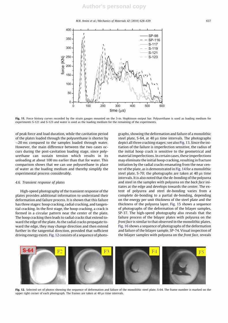
The force transmitted through the sample in the DB-IIsetup is measured using strain gauges mounted on the 3-in. Hopkinson output bar. The time-histories of the trans-mitted stress-pulse demonstrate a consistent pattern with
only some slight differences depending on the loadingmedium and the mode of sample failure; see Fig. 11. Fourdistinct stages of loading can be detected in all cases:Shock loading (pre-cavitation), cavitation, post-cavitationloading, and unloading. These stages can be described asfollows:
1. Shock loading (pre-cavitation loading). In this stage, theinitial transmitted shock pulse is transferred to thesample causing its initial deformation. The duration ofthis loading stage is less than 50 ms and the amplitudeof the load-peak is approximately 350 KN.
2. Cavitation. During this stage which lasts about 100 ms,the particle velocity of the sample is higher than theparticle velocity of the loading medium (water or poly-urethane). This particle velocity discontinuity causes apressure drop in the loading medium and consequentlya pressure relief stage results, during which the platecontinues to deform under its own kinetic energy.
3. Post-cavitation loading. The plate’s particle velocitydecreases during the cavitation stage and continuesuntil the water (or polyurethane) catches up and loadsthe sample again. The duration of this stage is approxi-mately 300 ms and the amplitude of the loading plateauis approximately 175 KN, displaying distinctly differentfeatures than those of the pre-cavitation. As shown inFig. 11, comparing the load history of the fractured
Fig. 7. Top view (left column) and side view (middle column) of a selected sample for each category of deformed steel plates: severely failed, moderatelyfailed, and not failed.
634 M.R. Amini et al. / Mechanics of Materials 42 (2010) 628–639
Author's personal copy
and unfractured samples, it follows that the fracturingof the sample reduces the loading duration of this stageby 75 ls.
4. Unloading. After the post-cavitation loading stage, thesample is unloaded and the average pressure in theloading medium drops back to zero. This stage is com-pleted within 150 ms after the post-cavitation loading.
4.5. Comparison of water and polyurethane
We have used both water and soft polyurethane as themedium through which the pressure pulse is transmittedto load the sample. The corresponding transmitted load-histories are presented in Fig. 11. The first stage of theloads has the same characteristics for both media in terms
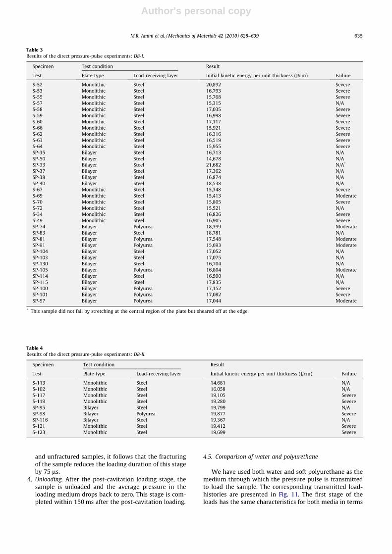
Table 3Results of the direct pressure-pulse experiments: DB-I.
Specimen Test condition Result
Test Plate type Load-receiving layer Initial kinetic energy per unit thickness (J/cm) Failure
S-52 Monolithic Steel 20,892 SevereS-53 Monolithic Steel 16,793 SevereS-55 Monolithic Steel 15,768 SevereS-57 Monolithic Steel 15,315 N/AS-58 Monolithic Steel 17,035 SevereS-59 Monolithic Steel 16,998 SevereS-60 Monolithic Steel 17,117 SevereS-66 Monolithic Steel 15,921 SevereS-62 Monolithic Steel 16,316 SevereS-63 Monolithic Steel 16,519 SevereS-64 Monolithic Steel 15,955 SevereSP-35 Bilayer Steel 16,713 N/ASP-50 Bilayer Steel 14,678 N/ASP-33 Bilayer Steel 21,682 N/A*
SP-37 Bilayer Steel 17,362 N/ASP-38 Bilayer Steel 16,874 N/ASP-40 Bilayer Steel 18,538 N/AS-67 Monolithic Steel 15,348 SevereS-69 Monolithic Steel 15,413 ModerateS-70 Monolithic Steel 15,805 SevereS-72 Monolithic Steel 15,521 N/AS-34 Monolithic Steel 16,826 SevereS-49 Monolithic Steel 16,905 SevereSP-74 Bilayer Polyurea 18,399 ModerateSP-83 Bilayer Steel 18,781 N/ASP-81 Bilayer Polyurea 17,548 ModerateSP-91 Bilayer Polyurea 15,693 ModerateSP-104 Bilayer Steel 17,052 N/ASP-103 Bilayer Steel 17,075 N/ASP-130 Bilayer Steel 16,704 N/ASP-105 Bilayer Polyurea 16,804 ModerateSP-114 Bilayer Steel 16,590 N/ASP-115 Bilayer Steel 17,835 N/ASP-100 Bilayer Polyurea 17,152 SevereSP-101 Bilayer Polyurea 17,082 SevereSP-97 Bilayer Polyurea 17,044 Moderate
* This sample did not fail by stretching at the central region of the plate but sheared off at the edge.
Table 4Results of the direct pressure-pulse experiments: DB-II.
Specimen Test condition Result
Test Plate type Load-receiving layer Initial kinetic energy per unit thickness (J/cm) Failure
S-113 Monolithic Steel 14,681 N/AS-102 Monolithic Steel 16,058 N/AS-117 Monolithic Steel 19,105 SevereS-119 Monolithic Steel 19,280 SevereSP-95 Bilayer Steel 19,799 N/ASP-98 Bilayer Polyurea 19,877 SevereSP-116 Bilayer Steel 19,367 N/AS-121 Monolithic Steel 19,412 SevereS-123 Monolithic Steel 19,699 Severe
M.R. Amini et al. / Mechanics of Materials 42 (2010) 628–639 635
Author's personal copy
Fig. 8. Selected bilayer samples deformed at different input energy per unit thickness: bilayer samples with polyurea cast onto front face (top row), andbilayer samples with polyurea cast onto back face (bottom row).
Fig. 9. Selected set of photos showing the sequence of the deformation and edge tearing (Frame 10) of steel-polyurea bilayer plate, SP-33 (polyurea on theback face). The frame number is marked at the upper right corner of each photograph. The frames are taken at 40 ls time intervals.
Fig. 10. Selected bilayer samples with indicated polyurea thickness, deformed at different (indicated) input energy per unit thickness. Bilayer samples withpolyurea cast onto front face (top row), and bilayer samples with polyurea cast onto back face (bottom row).
636 M.R. Amini et al. / Mechanics of Materials 42 (2010) 628–639
Author's personal copy
of peak force and load duration, while the cavitation periodof the plates loaded through the polyurethane is shorter by�20 ms compared to the samples loaded through water.However, the main difference between the two cases oc-curs during the post-cavitation loading stage, since poly-urethane can sustain tension which results in itsunloading at about 100 ms earlier than that for water. Thiscomparison shows that we can use polyurethane in placeof water as the loading medium and thereby simplify theexperimental process considerably.
4.6. Transient response of plates
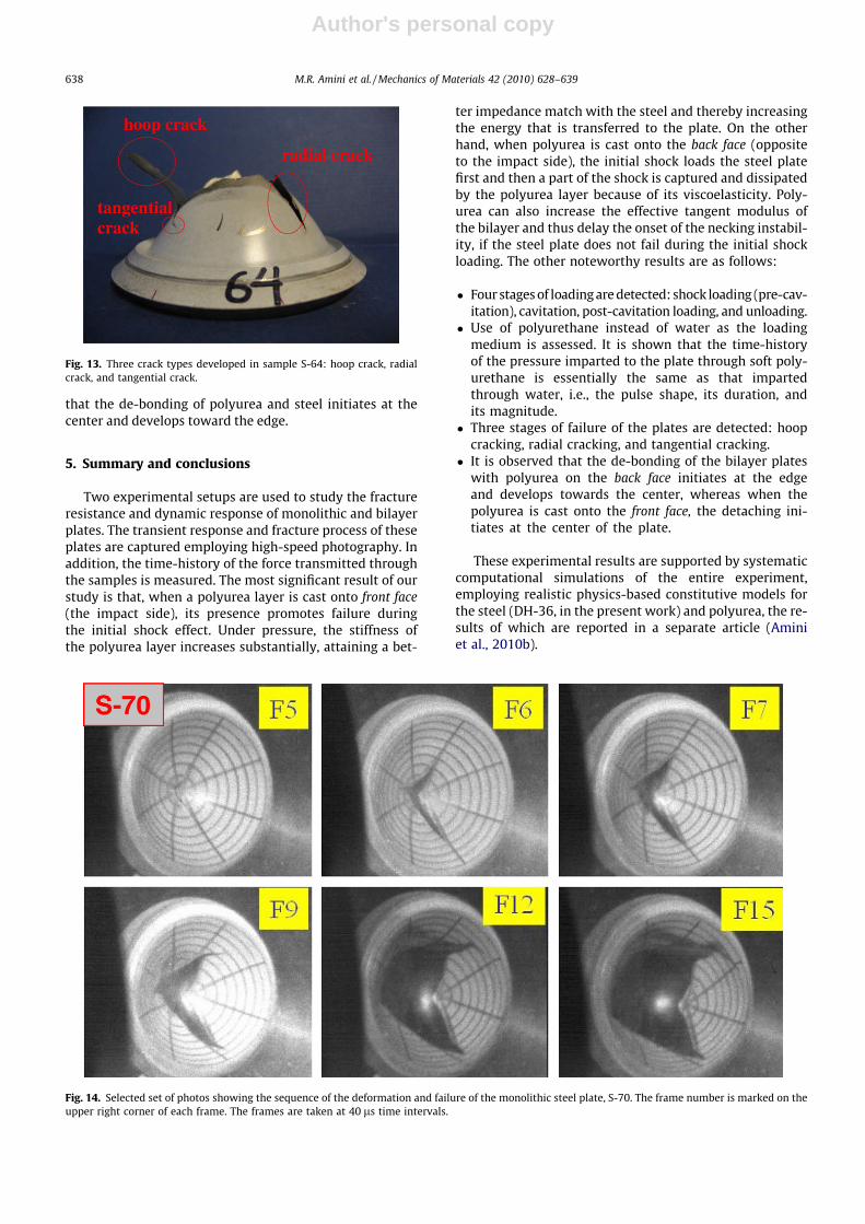
High-speed photography of the transient response of theplates provides additional information to understand theirdeformation and failure process. It is shown that this failurehas three stages: hoop cracking, radial cracking, and tangen-tial cracking. In the first stage, the hoop cracking, a crack isformed in a circular pattern near the center of the plate.The hoop cracking then leads to radial cracks that extend to-ward the edge of the plate. As the radial cracks propagate to-ward the edge, they may change direction and then extendfurther in the tangential direction, provided that sufficientdriving energy exists. Fig. 12 consists of a sequence of photo-
graphs, showing the deformation and failure of a monolithicsteel plate, S-64, at 40 ls time intervals. The photographsdepict all three cracking stages; see also Fig. 13. Since the ini-tiation of the failure is imperfection sensitive, the radius ofthe initial hoop crack is sensitive to the geometrical andmaterial imperfections. In certain cases, these imperfectionsmay eliminate the initial hoop cracking, resulting in fractureinitiation by the radial cracks emanating from the near cen-ter of the plate, as is demonstrated in Fig. 14 for a monolithicsteel plate, S-70; the photographs are taken at 40 ls timeintervals. It is also noted that the de-bonding of the polyureaand steel in the samples with polyurea on the back face ini-tiates at the edge and develops towards the center. The ex-tent of polyurea and steel de-bonding varies from acomplete de-bonding to a partial de-bonding, dependingon the energy per unit thickness of the steel plate and thethickness of the polyurea layer. Fig. 15 shows a sequenceof photographs of the deformation of the bilayer samples,SP-37. The high-speed photography also reveals that thefailure process of the bilayer plates with polyurea on thefront face is similar to that observed in the monolithic plates.Fig. 16 shows a sequence of photographs of the deformationand failure of the bilayer sample, SP-74. Visual inspection ofthe bilayer samples with polyurea on the front face, reveals
0 100 200 300 400 500 6000
50
100
150
200
250
300
350
400
forc
e (K
N)
time (µs)
SP-98SP-116S-117 S-119S-121S-123
Fig. 11. Force history curves recorded by the strain gauges mounted on the 3-in. Hopkinson output bar. Polyurethane is used as loading medium forexperiments S-121 and S-123 and water is used as the loading medium for the remaining of the experiments.
Fig. 12. Selected set of photos showing the sequence of deformation and failure of the monolithic steel plate, S-64. The frame number is marked on theupper right corner of each photograph. The frames are taken at 40 ls time intervals.
M.R. Amini et al. / Mechanics of Materials 42 (2010) 628–639 637
Author's personal copy
that the de-bonding of polyurea and steel initiates at thecenter and develops toward the edge.
5. Summary and conclusions
Two experimental setups are used to study the fractureresistance and dynamic response of monolithic and bilayerplates. The transient response and fracture process of theseplates are captured employing high-speed photography. Inaddition, the time-history of the force transmitted throughthe samples is measured. The most significant result of ourstudy is that, when a polyurea layer is cast onto front face(the impact side), its presence promotes failure duringthe initial shock effect. Under pressure, the stiffness ofthe polyurea layer increases substantially, attaining a bet-
ter impedance match with the steel and thereby increasingthe energy that is transferred to the plate. On the otherhand, when polyurea is cast onto the back face (oppositeto the impact side), the initial shock loads the steel platefirst and then a part of the shock is captured and dissipatedby the polyurea layer because of its viscoelasticity. Poly-urea can also increase the effective tangent modulus ofthe bilayer and thus delay the onset of the necking instabil-ity, if the steel plate does not fail during the initial shockloading. The other noteworthy results are as follows:
� Four stages of loading are detected: shock loading (pre-cav-itation), cavitation, post-cavitation loading, and unloading.
� Use of polyurethane instead of water as the loadingmedium is assessed. It is shown that the time-historyof the pressure imparted to the plate through soft poly-urethane is essentially the same as that impartedthrough water, i.e., the pulse shape, its duration, andits magnitude.
� Three stages of failure of the plates are detected: hoopcracking, radial cracking, and tangential cracking.
� It is observed that the de-bonding of the bilayer plateswith polyurea on the back face initiates at the edgeand develops towards the center, whereas when thepolyurea is cast onto the front face, the detaching ini-tiates at the center of the plate.
These experimental results are supported by systematiccomputational simulations of the entire experiment,employing realistic physics-based constitutive models forthe steel (DH-36, in the present work) and polyurea, the re-sults of which are reported in a separate article (Aminiet al., 2010b).
Fig. 13. Three crack types developed in sample S-64: hoop crack, radialcrack, and tangential crack.
Fig. 14. Selected set of photos showing the sequence of the deformation and failure of the monolithic steel plate, S-70. The frame number is marked on theupper right corner of each frame. The frames are taken at 40 ls time intervals.
638 M.R. Amini et al. / Mechanics of Materials 42 (2010) 628–639

Author's personal copy
Acknowledgments
This work has been supported by the ONR (MURI) grantN000140210666 to the University of California, San Diego,with Dr. Roshdy G. Barsoum as program manager.
References
Air Products and Chemicals, Inc., 2003. Polyurethane specialty products.(Air Products and Chemicals, Allentown, PA).
Amini, M.R., Isaacs, J., Nemat-Nasser, S., 2010a. Experimentalinvestigation of response of monolithic and bilayer plates toimpulsive loads. International Journal of Impact Engineering 37 (1),82–89.
Amini, M.R., Simon, J., Nemat-Nasser, S., 2010b. Numerical modeling ofeffect of polyurea on response of steel plates to impulsive loads in
direct pressure-pulse experiments. Mechanics of Materials 42, 615–627.
Amirkhizi, A.V., Isaacs, J., McGee, J., Nemat-Nasser, S., 2006. Anexperimentally-based viscoelastic constitutive model for polyurea,including pressure and temperature effects. Philosophical Magazineand Philosophical Magazine Letters 86 (36), 5847–5866.
Mock, W., Balizer, E., 2005. Penetration protection of steel plates withpolyurea layer. Presented at Polyurea Properties and Enhancement ofStructures under Dynamic Loads, Airlie, VA.
Nemat-Nasser, S., Guo, W.G., 2003. Thermomechanical response of DH-36structural steel over a wide range of strain rates and temperatures.Mechanics of Materials 35, 1023–1047.
The Dow Chemical Company, 2001. Isonate� 2143L; Modified MDI. (DowChemical, Midland, MI).
Xue, Z., Hutchinson, J.W., 2007. Neck retardation and enhanced energyabsorption in metal–elastomer bilayers. Mechanics of Materials 39,473–487.
Fig. 15. Selected set of photos showing the sequence of the deformation and de-bonding of the steel-polyurea bilayer plate, SP-37 (polyurea on the backface). The frame number is marked on the upper top right corner of each frame. The frames are taken at 40 ls time intervals.
Fig. 16. Selected set of photos showing the sequence of the deformation and fracture of the steel-polyurea bilayer plate, SP-74 (polyurea on the front face).The frame number is marked on the upper right corner side of each frame. The frames are at 40 ls time intervals.
M.R. Amini et al. / Mechanics of Materials 42 (2010) 628–639 639