Embed Size (px)
Citation preview

1
title: Fabrication of Polymer Solar Cells (PSCs): Can a ternary device perform better? A
preliminary lab report.
authors: Peter Dimoulas and Dr. Su Huang.
last updated : August 1, 2014
Introduction
We fabricated polymer solar cells (PSCs) on planar substrates. Our goal was to characterize the
performance of PSCs with 2 donors - 1 acceptor systems (ternary PSC) in relation to that of PSCs
with 1 active donor - 1 acceptor system.
A ternary PSC involves two distinct active polymer, donor-acceptor interfaces, as well as a donor-
donor interface, in contrast to a single donor-acceptor interface for standard PSCs. Ternary PSCs
have the potential to widen the effective wavelengths and increase the percent absorption thereby
enhancing the power conversion efficiency (PCE) and peak, or open-circuit voltage (Voc).
Moreover, an additional donor-donor interface may yield finer phase separation, which is ideal for
charge separation at the donor-acceptor interface (L. Gang et al., 2012). On the other hand, the
resultant energy cascades may be negatively impacted by competing donor-acceptor systems (Y.-
C. Chen et al., 2013). Furthermore, the stability and processability of the polymers requires
careful consideration in order to optimize the performance of the two, polymer donor-acceptor
interfaces. For the purposes of our study we used the following polymers: PTB7, Poly({4,8-bis[(2-
ethylhexyl)oxy]benzo[1,2-b:4,5-b′]dithiophene-2,6-diyl}{3-fluoro-2-[(2-
ethylhexyl)carbonyl]thieno[3,4-b]thiophenediyl}); P3HT, Poly(3-hexylthiophene-2,5-diyl); PCBM,
Phenyl-C61-butyric acid methyl ester.
Regarding stability and processability of PTB7, several studies have fabricated and encapsulated
PBT7-based devices within an N2 environment, within a glove box (Y. Liang et al. 2009 and 2010;
and J. You et al. 2012). Presumably, this was to account for PTB7’s air sensitivity. Unfortunately,
this was not possible given our facilities. Additionally, recent studies have annealed PTB7-based
devices at room temperature (A. Guerrero et al. 2013; H.-Y. Park et al. 2013; S. Cho et al. 2014;
and T. Yanagidate et al. 2014). Interestingly, Dr. Su Huang previously annealed a PTB7:PCBM
device at 120°C for 10 minutes and found significant charge leakage. On the other hand, P3HT is
not known to be particularly air-sensitive. In terms of annealing, Dr. Su Huang has found that,
under conditions within our facilities, P3HT-based devices yield their best results when then
annealed at 160°C for 10 minutes (Voc = 0.63; PCE = 4.3, fill factor (FF) = 0.4; photocurrent
density (A/m2) = 141).
We examined the performance of several batches of PSCs with a variety of PTB7: P3HT: PCBM
ratios that were annealed at temperatures ranging from 22°C to 165°C. Our aim was to realize
conditions suitable for fabricating a PTB7: P3HT: PCBM based ternary PSC with enhanced
performance relative to either single, polymer interface system.
methods

2
Planar substrates that include ITO on glass obtained from Candice Veligra and Noga Kornblum.
Substrates subsequently underwent oxygen, plasma cleaning within a vacuum for 10 minutes.
Filtered polymer solutions, which were passed through a filter (0.2um PTFE with 13mm diameter),
were spin-coated onto substrates. Prior to the filtering and throughout the spin-coating processes
polymer solutions were placed on a hot plate at 65°C to maintain lower solution viscosity. Coated
substrates were transferred into a glove box (with a nitrogen environment) and annealed.
Following annealing of spin-coated polymer solutions for 10 minutes, layers of MoO3 and Ag were
deposited via thermal evaporation within a vacuum. Finished devices were tested in ambient air
using PV-measurement software, from which we obtained the following measurements: open-
circuit voltage (Voc), fill factor (FF), photocurrent density, and power conversion efficiency (PCE).
For more specific information on how specific samples were treated please see table 1. Light
used to test devices is passed through a KG5 filter (300-800 nm) that is applied to better simulate
sunlight.
Results
Among the devices with single active-donor interfaces PTB7:PCBM outperformed P3HT:PCBM for
each parameter tested, including Voc, FF, photocurrent density, and PCE (tables 2 and 3).
Regardless, of annealing conditions, neither ternary device outperformed PTB7:PCBM; however,
most of ternary devices did realize a similar or improved Voc relative to P3HT:PCBM (figs. 1-4).
On average, for Voc, photocurrent density, and PCE, our ternary devices realized improved
performance at higher annealing temperatures; although, we did not find a consistent relationship
between annealing temperature and FF among polymer systems and conditions that were
considered (figs. 1-4). We also obtained similar results for 2 devices that were tested following
annealing at 2 distinct temperatures (table 4).
We also found that PTB7 devices annealed at 22°C realized an asymptotic rise in Voc and PCE
as a function of time spent exposed to our light source (figs. 5 & 8); though, we did observe an
initial rise rise in FF and photocurrent, it was more modest (figs. 6 & 7). For sample 5, PTB7: 2.5,
P3HT: 7, PCBM (from July 21), we periodically turned off the light source and subsequently found
decreases in Voc, FF, photocurrent density, and PCE.
Discussion
We fabricated several PSCs with varying ratios of PTB7, P3HT, and PCBM. Our goal was to
elucidate conditions via which a ternary device, with 2 donor-acceptor systems, PTB7: PCBM and
P3HT: PCBM, would out-perform either single donor-acceptor system. We found that some of our
ternary devices did realize an elevated Voc relative to a P3HT: PCBM donor systems; however,
this was not the case for our ternary devices in terms of FF, photocurrent density, or PCE
compared with either PTB7: PCBM or P3HT: PCBM donor systems. Among our ternary devices,
we found a positive relationship for Voc, photocurrent density, and PCE with increasing annealing
temperature; although, we did not find such a relationship for FF. Additionally, individual ternary
devices tested following annealing at room temperature and retested following annealing at a

3
higher temperature also realized an increase in Voc, photocurrent density, and PCE but not for
FF.
Our P3HT:PCBM devices performed on par when compared to those completed by previous
studies (Gang et al., 2005; Reyes-Reyes et al.; 2005); however, our PTB7:PCBM devices did not
perform as well (A. Guerrero et al., 2013.; H.-Y. Park et al., 2013.; Yanagidate et al., 2014). We
believe that this difference can be attributed to our fabrication conditions. In fact, those studies
fabricated and tested their devices entirely within a glove box (with a nitrogen environment), in
addition to annealing at room temperature, and only exposed their device to air after it was
encapsulated. We propose that PTB7 is air (or oxygen) sensitive, exposure to which may limit its
ability to generate excitons.
Regarding device performance and changes in annealing temperatures, previous work revealed
that P3HT:PCBM devices generally realized enhanced performance when annealed at higher
temperatures, although this relationship is time-dependent and device performance can
deteriorate, eventually (Gang et al., 2005; Reyes-Reyes et al.; 2005). The authors suggested that
annealing at higher temperatures tends to tighten packing of P3HT polymer chains, which better
enable the generation and separation of excitons. Among our findings, we examined Voc and
PCE as a function of annealing temperature and percent composition (of P3HT and PTB7) and
found no noticeable or consistent relationship (figs. 9 and 10, and table 5).
Ternary PSCs have the potential to realized enhanced performance (L. Gang et al., 2012).
Indeed, we found that under specific conditions PTB7:P3HT:PCBM devices realized elevated Voc
relative to P3HT:PCBM alone, but not compared to PTB7:PCBM; additionally, the FF,
photocurrent density, and PCE of our ternary PSCs were less than that of both P3HT:PCBM and
PTB7:PCBM devices. Unfortunately, PTB7-based devices realized optimal performance when
fabricated within an inert environment and annealed at room temperature and P3HT-devices
perform better when annealed at higher temperatures. Therefore, we believe that our ternary
devices did not perform as well as due to the disparate processing conditions under which PTB7-
and P3HT- based PSCs perform best.
Although we found that our ternary PSCs tended not to perform as well as single-interface PSCs,
provided that multiple polymers can be processed under similar conditions; and realize phase
separation, based on their inherent polar or non-polar properties, on the order of 10-20 nms,
consistent with the working distance of excitons; ternary PSCs should perform better. Going
forward, future studies should carefully consider selection of appropriate polymers with similar,
optimal processing conditions.
Acknowledgements
This research was primarily supported by NSF Grant MRSEC DMR 111-9826 (CRISP Research
Experiences for Teachers Program). Additionally, thank you to CRISP, Professor Christine
Broadbridge and Carol Jenkins for administering this program and making this work possible. A
special thanks to Dr. Su Huang, my mentor and device making guru. I would also like to thank
Candice Pelligra and Noga Kornblum, for fabricating substrates (including ZnO nanorod forests).

4
Thank you to Professor Chinedum Osuji for welcoming me into his lab and providing additional
guidance and support for this work. Finally, thank you to all the members of the Osuji lab for
being warm and friendly as well as keeping a high-energy and motivating environment.

5
References
Chen, Y.-C.; C.-Y. Hsu; R. Y.-Y. Lin; K.-C. Ho; and J.T. Lin. (2013). Materials for Active Layer of
Organic Photovoltaics Ternary Solar Cell Approach. Chem. SUS Chem Reviews (6): 20-35.
Gang, L.; V. Shrotriya; Y. Yao; and Y. Yang. (2005). Investigation of annealing effects and film
thickness dependence of polymer solar cells based on poly(3-hexylthiophene). Joumal of
Applied Physics; 98, 043704.
Guerrero, A.; N.F. Montcada; J. Ajuria; I. Etxebarria; R. Pacios; G. Garcia-Belmonte; and E.
Palomares. (2013). Charge carrier transport and contact selectivity limit the operation of
PTB7-based organic solar cells of varying active layer thickness. Journal of Material
Chemistry, A (1): 12345-54.
Huang, S. (2014, July). Personal Communication.
Liang, Y.; Z. Xu; J. Xia; S.-T. Tsai; Y. Wu; G. Li; C. Ray; and L. Yu. (2010). For the Bright Future -
Bulk Heterojunction Polymer Solar cells with Power Conversion Efficiency of 7.4%.
Advanced Materials (22): E135-8.
Park, H.-Y.; D. Lim; K.-D. Kim; and S.-Y. Jang. (2013). Performance of low-temperature-annealed
solution-processible ZnO buffer layers for inverted solar cells. Journal of Material
Chemistry, A (1): 6327-34.
Reyes-Reyes, M.; K Kim; and D.L. Carrolla. (2005). High-efficiency photovoltaic devices based on
annealed poly„3-hexylthiophene… and 1-„3-methoxycarbonyl… -propyl-1-phenyl-„6,6…C61
blends. Applied Physics Letters (87), 083506.
Yanagidate, T.; S. Fujii; M. Ohzeki; Y. Yanagi; Y. Arai; T. Okukawa; A. Yoshida; H. Kataura; and
Y. Nishioka. (2014). Flexible PTB7:PC71BM bulk heterojunction solar cells with LiF buffer
layer. Japanese Journal of Applied Physics (53): 2BE05.
You, J.; C.-C. Chen; L. Dou; S. Murase; H.-S. Duan; S.A. Hawks; T. Xu; H.-J. Son; L. Yu; G. Li;
and Y. Yang. (2012). Metal Oxide Nanoparticles as an Electron-Transport Layer in High-
Performance and Stable Inverted Polymer Solar Cells. Advanced Materials (24): 5267-72.

6
Figures
Figure 1
Figure 2

7
Figure 3
Figure 4

8
Figure 5
Lights were turned off for sample 3b between 9:20-14:05, 15:11-27:49, and 45:18-1:16:59; for
sample 5, PTB7: 2.5, P3HT: 7, PCBM between 1:02:53-1:23:23.
Figure 6
Lights were turned off for sample 3b between 9:20-14:05, 15:11-27:49, and 45:18-1:16:59; for
sample 5, PTB7: 2.5, P3HT: 7, PCBM between 1:02:53-1:23:23.

9
Figure 7
Lights were turned off for sample 3b between 9:20-14:05, 15:11-27:49, and 45:18-1:16:59; for
sample 5, PTB7: 2.5, P3HT: 7, PCBM between 1:02:53-1:23:23.
Figure 8
Lights were turned off for sample 3b between 9:20-14:05, 15:11-27:49, and 45:18-1:16:59; for
sample 5, PTB7: 2.5, P3HT: 7, PCBM between 1:02:53-1:23:23.

10
figure 9
figure 10

11
Tables
fabrication
date
test
date
sample
IDs
polymer
solvent
polymer ratio spin-coating
(rpms)
annealing
temperature (°C)
7/9/14 7/9/14 A 3% DIO,in
Cl-benzene
5, PTB7: 20,
P3HT: 19,
PCBM
2000 22
7/9/14 7/9/14 C 3% DIO,in
Cl-benzene
5, PTB7: 20,
P3HT: 19,
PCBM
2000 90
7/9/14 7/9/14 F 3% DIO,in
Cl-benzene
5, PTB7: 20,
P3HT: 19,
PCBM
2000 120
7/11/14 7/11/14 A Cl-benzene 5, PTB7: 20,
P3HT: 12,
PCBM
2000 120
7/11/14 7/11/14 C Cl-benzene 5, PTB7: 20,
P3HT: 12,
PCBM
2000 140
7/15/14 7/15/14 1a Cl-benzene 20, P3HT: 12,
PCBM
3500 165
7/17/14 7/17/14 2b Cl-benzene 5, PTB7: 7,
PCBM
1000 22
7/18/14 7/21/14 4a Cl-benzene 5, PTB7: 2.5,
P3HT: 7, PCBM
1000 22
7/18/14 7/21/14 4a1 Cl-benzene 5, PTB7: 2.5,
P3HT: 7, PCBM
1000 95
7/18/14 7/21/14 3a Cl-benzene 5, PTB7: 2.5,
P3HT: 7, PCBM
1000 22
7/18/14 7/21/14 3a1 Cl-benzene 5, PTB7: 2.5,
P3HT: 7, PCBM
1000 121
Table 1
1 samples were initially tested and then retested after annealing in ambient air.

12
The above table includes more detailed information regarding how specific samples were treated
prior to testing, obtaining I-V curves.
13
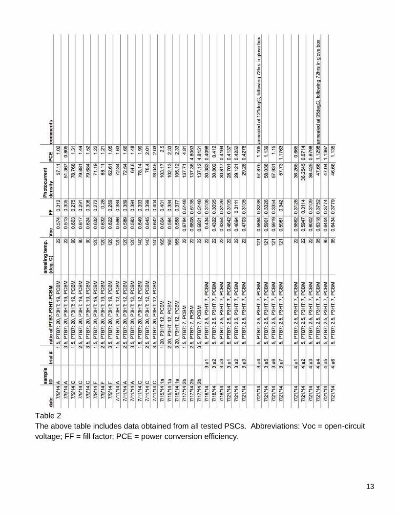
Table 2
The above table includes data obtained from all tested PSCs. Abbreviations: Voc = open-circuit
voltage; FF = fill factor; PCE = power conversion efficiency.

14
date sample ID
ratio of PTB7-P3HT-PCBM
annealing temp. (°C)
Voc FF Photocurrent density
PCE
7/9/14 A 5, PTB7: 20, P3HT: 19, PCBM
22 0.544 0.31 54.239 0.913
7/9/14 C 5, PTB7: 20, P3HT: 19, PCBM
90 0.615 0.29 79.444 1.423
7/9/14 F 5, PTB7: 20, P3HT: 19, PCBM
120 0.629 0.27 67.303 1.160
7/11/14 A 5, PTB7: 20, P3HT: 12, PCBM
120 0.586 0.39 69.827 1.590
7/11/14 C 5, PTB7: 20, P3HT: 12, PCBM
140 0.645 0.40 78.195 2.010
7/15/14 1a 20, P3HT: 12, PCBM
165 0.595 0.39 103.473 2.387
7/17/14 2b 5, PTB7: 7, PCBM 22 0.680 0.51 137.403 4.810
7/21/14 4a 5, PTB7: 2.5, P3HT: 7, PCBM
22 0.593 0.31 36.3148 0.672
7/21/14 4a 5, PTB7: 2.5, P3HT: 7, PCBM
95 0.638 0.38 47.1267 1.134
7/21/14 3a 5, PTB7: 2.5, P3HT: 7, PCBM
22 0.468 0.31 29.034 0.422
7/21/14 3a 5, PTB7: 2.5, P3HT: 7, PCBM
121 0.592 0.33 57.8935 1.143
Table 3
The above table includes average findings, calculated from the raw data (table 2).

15
sample ID annealing regime (°C)
Voc FF Photocurrent density
PCE
4a 22-95 0.076 0.209 0.298 0.687
3a 22-121 0.265 0.073 0.994 1.706
Table 4
The above table indicates the fractional improvement in Voc, FF, photocurrent density, and PCE
for PSCs fabricated on July 18, 2014 and tested on July 21, 2014. Baseline data was obtained
following annealing at 22°C. Samples were subsequently annealed, for a second time in ambient
air, and retested.
date sample ID
ratio of PTB7-P3HT-PCBM
Percent P3HT (%)
annealing temp. (deg. C)
Voc PCE
7/17/14 2b 5, PTB7: 7, PCBM 0 22 0.680 4.810
7/21/14 4a 5, PTB7: 2.5, P3HT: 7, PCBM
33 22 0.594 0.672
7/9/14 A 5, PTB7: 20, P3HT: 19, PCBM
80 22 0.544 0.913
7/9/14 C 5, PTB7: 20, P3HT: 19, PCBM
80 90 0.615 1.423
7/21/14 4a 5, PTB7: 2.5, P3HT: 7, PCBM
33 95 0.639 1.134
7/21/14 3a 5, PTB7: 2.5, P3HT: 7, PCBM
33 121 0.592 1.143
7/11/14 A 5, PTB7: 20, P3HT: 12, PCBM
80 120 0.586 1.590
7/11/14 C 5, PTB7: 20, P3HT: 12, PCBM
80 140 0.645 2.010
7/15/14 1a 20, P3HT: 12, PCBM 100 165 0.595 2.387
Table 5
The above table includes average findings including with figures 9 and 10. Percent P3HT was
obtained by dividing the mass of P3HT (within solution) by the total mass, or sum of PTB7 and
P3HT.


![MixtureDifferentialCryptanalysisandStructural ... › 2017 › 832.pdf · YoyoGame 4 2CP+2ACC 2XOR [RBH17] ImpossibleDifferential 4 216.25 CP 222 3 M≈216 E [BK01] MixtureDiff](https://img.pdfslide.us/doc/110x75/5f143c29d734996e930a8ce8/mixturediierentialcryptanalysisandstructural-a-2017-a-832pdf-yoyogame.jpg)