Embed Size (px)
Citation preview
Page | 1
Australian Wiring Instructions:
Generator/Switch Wiring: Remove the generator controller fascia and identify wire #44 going to the
circuit breaker in the external connection box, this wire is the active (hot) wire and has a piece of brown
heat shrink for identification to coincide with Australian standard structural wiring. Wire #11, also going
to the generator breaker is the neutral and it has a piece of blue heat shrink on it for identification.
Wire 11 (Neutral)
Wire 44 (Active)
Generator Circuit Breaker
Page | 2
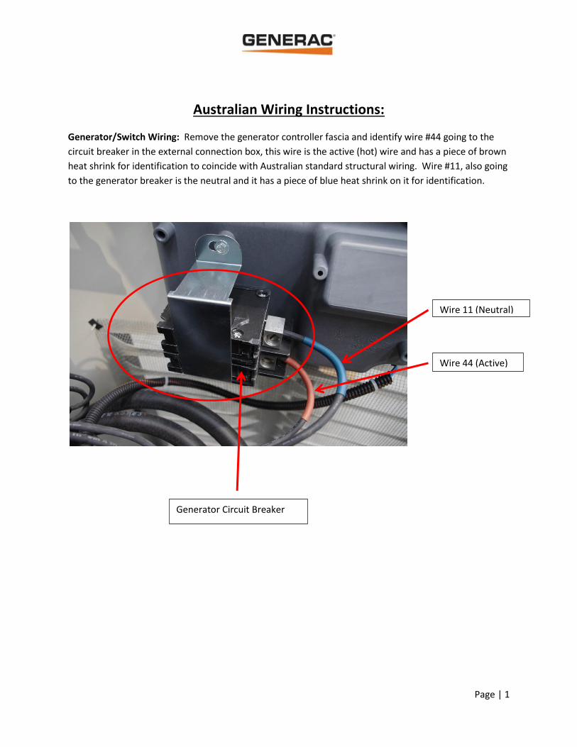
The installer will need to provide a NEMA 3R box to house a 35, 50 or 65 amp, Australian approved
single pole breaker which can be mounted on the building or on the generator itself. The installer would
connect the brown conductor (hot wire) to the opposite side of the circuit breaker that is fed by wire
#44 identified by the brown heat shrink. This wire is then fed into the NEMA 3R box and connected on
the input side of the Australian approved breaker. Another brown conductor will be run out of the box
after being protected on the output side of the Australian breaker and fed to the transfer switch. An
example of the required box is pictured below, it can be found at any electrical distributor for less than
$30.
A blue conductor (neutral) will be connected to the breaker opposite to the wire identified as #11 and
identified by the blue heat shrink. This conductor is then run to the transfer switch. It does not need to
be routed with the brown conductor but can be for ease of wire routing/conduit connection.
Installer provided NEMA 3R box
and Australian approved breaker
Generator circuit breaker Neutral
Active
Page | 3
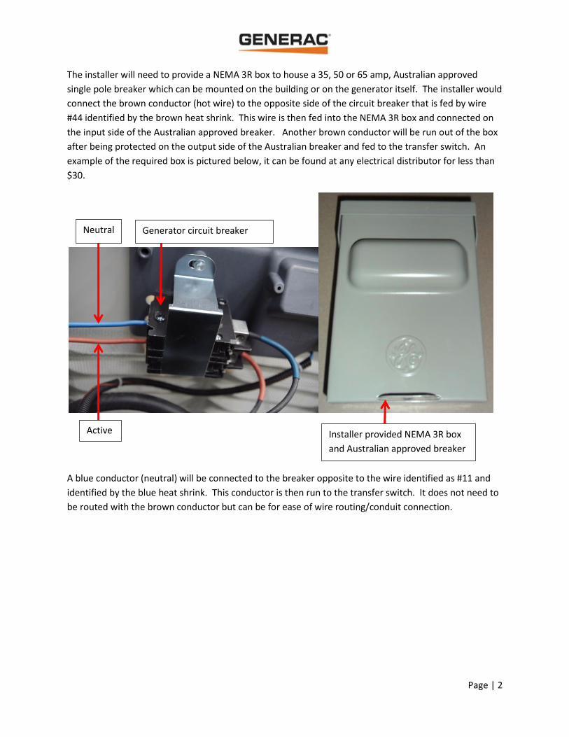
A green/yellow conductor (earth) will be landed on the ground block connector in the generator
connection shelf, then run to the transfer switch. It does not need to be routed with the brown (active)
conductor but can be for ease of wire routing/conduit connection.
Connect your control wires (N1, N2, 23, 194, T1 & T2) to the appropriate landings on the generator
connection shelf. NOTE: In this application, T2 will be landed on the main neutral post.
These wires can be run in the same conduit as the power wires if the proper insulation is used.
Earth/Ground
Land T2 wire here to
the Neutral post
Control wires N1, N2, 23, 194, T1

Page | 4
RTS Transfer Switch:
After mounting the switch, remove the cover to make the electrical connections. Please note that if
being used in an application to back up the entire electrical panel, this switch requires a disconnect be
installed between the electrical meter and transfer switch since this is a non-service rated switch.
Next, install a jumper wire between the provided Neutral block and Earth ground. See below.
Page | 5
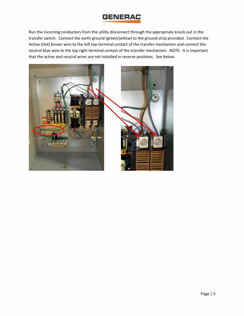
Run the incoming conductors from the utility disconnect through the appropriate knock out in the
transfer switch. Connect the earth ground (green/yellow) to the ground strip provided. Connect the
Active (Hot) brown wire to the left top terminal contact of the transfer mechanism and connect the
neutral blue wire to the top right terminal contact of the transfer mechanism. NOTE: It is important
that the active and neutral wires are not installed in reverse positions. See below.
Page | 6
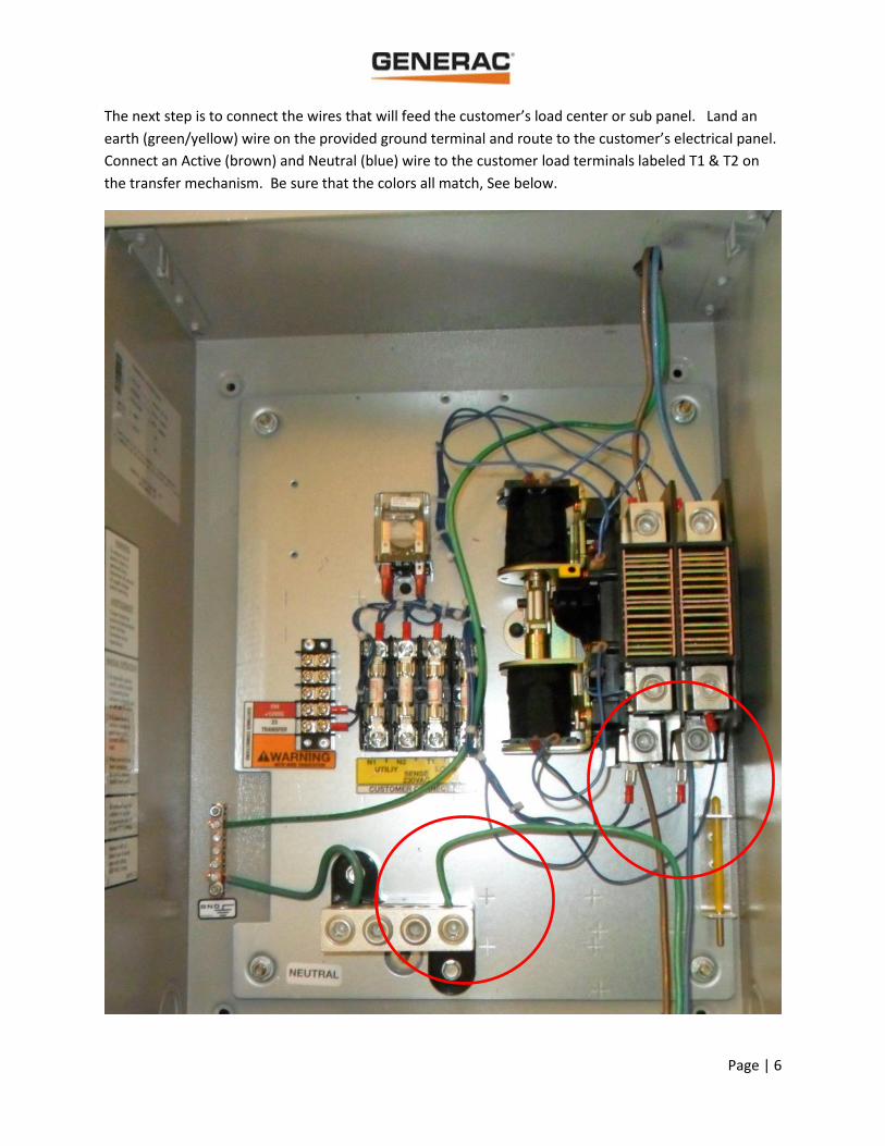
The next step is to connect the wires that will feed the customer’s load center or sub panel. Land an
earth (green/yellow) wire on the provided ground terminal and route to the customer’s electrical panel.
Connect an Active (brown) and Neutral (blue) wire to the customer load terminals labeled T1 & T2 on
the transfer mechanism. Be sure that the colors all match, See below.
Page | 7
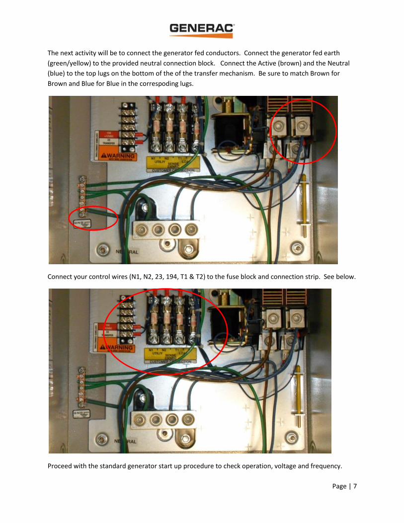
The next activity will be to connect the generator fed conductors. Connect the generator fed earth
(green/yellow) to the provided neutral connection block. Connect the Active (brown) and the Neutral
(blue) to the top lugs on the bottom of the of the transfer mechanism. Be sure to match Brown for
Brown and Blue for Blue in the correspoding lugs.
Connect your control wires (N1, N2, 23, 194, T1 & T2) to the fuse block and connection strip. See below.
Proceed with the standard generator start up procedure to check operation, voltage and frequency.
![Classic · PDF file16-Pulse GM / Chrysler Signal Generator [SN16] _____ 2 Ford Signal Generator Adapter [SN17] _____ 2 3 ⅜” Speedometer Wiring to SN16 _____ 3 4 5/ 8” Speedometer](https://img.pdfslide.us/doc/110x75/5a8543387f8b9a9f1b8c5919/classic-gm-chrysler-signal-generator-sn16-2-ford-signal-generator-adapter.jpg)