Embed Size (px)
Citation preview
AusNet Transmission Group Pty Ltd
Transmission Revenue Review 2017-2022
Revised Revenue Proposal
Appendix 3G: East Rowville Terminal Station Planning Report
Public Version
Submitted: 21 September 2016
Electricity Transmission Network
Planning Report Project TD-0003440
East Rowville Terminal Station Transformer Replacement
Document number
Issue number 1
Status Final
Approver J Bridge
Date of approval 8/09/2016
AusNet Services
Project Planning Report TD-0003440 – ERTS Transformer Replacement
ISSUE 1 9/9/2016 2 / 28
UNCONTROLLED WHEN PRINTED
ISSUE/AMENDMENT STATUS
Issue Number
Date Description Author Approved by
1 8/09/2016 Final Report H De Beer J Bridge
Disclaimer
This template is for generating internal and external document belonging to AusNet Services and may or may not contain all available information on the subject matter this document purports to address.
The information contained in this document is subject to review and AusNet Services may amend this document at any time. Amendments will be indicated in the Amendment Table, but AusNet Services does not undertake to keep this document up to date.
To the maximum extent permitted by law, AusNet Services makes no representation or warranty (express or implied) as to the accuracy, reliability, or completeness of the information contained in this document, or its suitability for any intended purpose. AusNet Services (which, for the purposes of this disclaimer, includes all of its related bodies corporate, its officers, employees, contractors, agents and consultants, and those of its related bodies corporate) shall have no liability for any loss or damage (be it direct or indirect, including liability by reason of negligence or negligent misstatement) for any statements, opinions, information or matter (expressed or implied) arising out of, contained in, or derived from, or for any omissions from, the information in this document.
Contact
This document is the responsibility of the Asset Management Division of AusNet Services. Please contact the indicated owner of the document with any inquiries.
J Bridge
AusNet Services
Level 31, 2 Southbank Boulevard
Melbourne Victoria 3006
Ph: (03) 9695 6000
AusNet Services
Project Planning Report TD-0003440 – ERTS Transformer Replacement
ISSUE 1 9/9/2016 3 / 28
UNCONTROLLED WHEN PRINTED
Table of Contents
1 Executive Summary ..................................................................................................................... 4
1.1 Responsibility .............................................................................................................................................. 4
1.2 Emerging Constraints ................................................................................................................................. 4
1.3 Economic Option ......................................................................................................................................... 4
2 Purpose ......................................................................................................................................... 5
3 Regulatory Obligations and Customer Requirements ............................................................. 5
4 Background .................................................................................................................................. 6
5 Planning Considerations ............................................................................................................. 9
5.1 Planning Responsibilities ............................................................................................................................ 9
5.2 Demand ....................................................................................................................................................... 9
5.3 Future Planning Requirements ................................................................................................................ 11
6 Asset Condition .......................................................................................................................... 12
6.1 220/66 kV Power Transformers ............................................................................................................... 12
6.2 220 kV Circuit Breakers ............................................................................................................................ 13
6.3 66 kV Circuit Breakers .............................................................................................................................. 13
6.4 Secondary Systems .................................................................................................................................. 14
7 Emerging Constraints................................................................................................................ 15
7.1 Safety and Environmental Hazards ......................................................................................................... 15
7.2 Safety, Plant Collateral Damage and Environmental Risk Cost ............................................................. 15
7.3 Reliability and Security of Supply Risk ..................................................................................................... 16
7.4 Baseline Risk ............................................................................................................................................. 17
8 Options to Address Risks ......................................................................................................... 19
9 Evaluation of Options ................................................................................................................ 19
9.1 Option 1: Business as Usual .................................................................................................................... 19
9.2 Option 2: Non network options of embedded generation and/or demand side response .................... 20
9.3 Option 3: Run to failure ............................................................................................................................. 20
9.4 Option 4: Integrated Replacement ........................................................................................................... 20
9.5 Option 5: Staged Replacement – Defer Replacement of Two Transformers ........................................ 20
9.6 Option 6: Staged Replacement – Defer Circuit Breaker Replacements ................................................ 21
9.7 PV Analysis ............................................................................................................................................... 22
9.8 Economic Option and Economical Timing ............................................................................................... 23
9.9 Sensitivity Studies ..................................................................................................................................... 24
10 Scope of Work ............................................................................................................................ 27
AusNet Services
Project Planning Report TD-0003440 – ERTS Transformer Replacement
ISSUE 1 9/9/2016 4 / 28
UNCONTROLLED WHEN PRINTED
1 Executive Summary
1.1 Responsibility
AusNet Transmission Group (AusNet Services) as a Transmission Network Service Provider (TNSP) in the state of Victoria has the ownership, operation and maintenance responsibility for East Rowville Terminal Station (ERTS). TNSP obligations include maintaining a safe working environment for staff and contractors, maintaining the quality, reliability and security of customer supplies, and preventing operating and maintenance costs from escalating to inefficient levels.
1.2 Emerging Constraints
ERTS was developed in the 1970’s. The majority of the electricity assets at ERTS are 45 years old and condition assessments indicate that several assets are approaching the end of their technical lives. The emerging service constraints are:
• Health and safety risks presented by a possible explosive failure of 220 kV circuit breaker bushings, 66 kV bulk oil circuit breakers or transformer bushings;
• Security of supply risks presented by a failure of the 220/66 kV transformers, 220 kV circuit breakers or 66 kV circuit breakers;
• Collateral plant damage risks presented by an explosive failure of a transformer bushing, 220 kV circuit breaker bushing or bulk oil 66 kV circuit breaker bushing;
• Environmental risks associated with insulating oil spill or fire.
1.3 Economic Option
This planning study considers credible options to address the service constraints and to meet the long term planning requirements for ERTS outlined in the Victorian Annual Planning Report and Transmission Connection Planning Report (TCPR). The options that have been assessed are:
• Business as usual to define the baseline risk;
• Non network option of embedded generation and/or demand side response;
• Run to failure and replace assets upon failure;
• Integrated asset replacement;
• Staged asset replacement;
The most economic option to address the emerging constraints at ERTS is an integrated asset replacement project that replaces the three [C-I-C] 220/66 kV transformers and selected 220 kV and 66 kV circuit breakers. This option has the lowest present value cost ($27.1 M) and is consistent with the future development plans for ERTS. The economic timing for project completion is 2019/20 with an estimated total capital cost of $22.1 M ($19.8 M direct $2016).
AusNet Services
Project Planning Report TD-0003440 – ERTS Transformer Replacement
ISSUE 1 9/9/2016 5 / 28
UNCONTROLLED WHEN PRINTED
2 Purpose
This planning report outlines asset condition, asset failure risks and network development plans relevant to ERTS for the planning period from 2016/17 to 2025/26. It provides an analysis of viable options to address the identified risks and maintain the efficient delivery of electrical energy from ERTS consistent with the National Electricity Rules (NER) and stakeholder’s requirements. It also summarizes the scope, delivery schedule and expenditures associated with the most economical solution to emerging constraints.
3 Regulatory Obligations and Customer Requirements
This planning report acknowledges AusNet Services’ obligations as a TNSP under the National Electricity Rules with particular emphasis on:
Clause 6A.6.7 of the National Electricity Rules requires AusNet Services to propose capital expenditures necessary to:
(1) meet or manage the expected demand for prescribed transmission services over that period;
(2) comply with all applicable regulatory obligations or requirements associated with the provision of
prescribed transmission services;
(3) to the extent that there is no applicable regulatory obligation or requirement in relation to:
(i) the quality, reliability or security of supply of prescribed transmission services; or
(ii) the reliability or security of the transmission system through the supply of prescribed transmission
services,
to the relevant extent:
(iii) maintain the quality, reliability and security of supply of prescribed transmission services; and
(iv) maintain the reliability and security of the transmission system through the supply of prescribed
transmission services; and
(4) maintain the safety of the transmission system through the supply of prescribed transmission services.
The Electricity Safety Act (section 98(a)) requires AusNet Services to “design, construct, operate, maintain and decommission its supply network to minimise the hazards and risks, so far as is practicable, to the safety of any person arising from the supply network; having regard to the:
a) severity of the hazard or risk in question; and
b) state of knowledge about the hazard or risk and any ways of removing or mitigating the hazard or
risk; and
c) availability and suitability of ways to remove or mitigate the hazard or risk; and
d) cost of removing or mitigating the hazard or risk”.
AusNet Services
Project Planning Report TD-0003440 – ERTS Transformer Replacement
ISSUE 1 9/9/2016 6 / 28
UNCONTROLLED WHEN PRINTED
4 Background
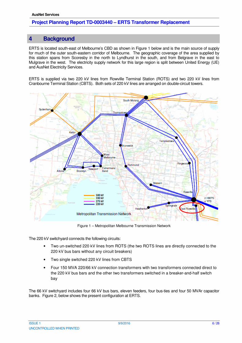
ERTS is located south-east of Melbourne’s CBD as shown in Figure 1 below and is the main source of supply for much of the outer south-eastern corridor of Melbourne. The geographic coverage of the area supplied by this station spans from Scoresby in the north to Lyndhurst in the south, and from Belgrave in the east to Mulgrave in the west. The electricity supply network for this large region is split between United Energy (UE) and AusNet Electricity Services.
ERTS is supplied via two 220 kV lines from Rowville Terminal Station (ROTS) and two 220 kV lines from Cranbourne Terminal Station (CBTS). Both sets of 220 kV lines are arranged on double-circuit towers.
Figure 1 – Metropolitan Melbourne Transmission Network
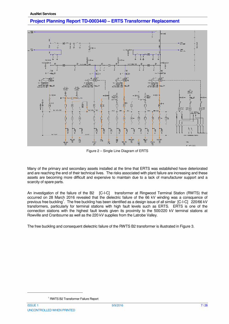
The 220 kV switchyard connects the following circuits:
• Two un-switched 220 kV lines from ROTS (the two ROTS lines are directly connected to the
220 kV bus bars without any circuit breakers)
• Two single switched 220 kV lines from CBTS
• Four 150 MVA 220/66 kV connection transformers with two transformers connected direct to
the 220 kV bus bars and the other two transformers switched in a breaker-and-half switch
bay
The 66 kV switchyard includes four 66 kV bus bars, eleven feeders, four bus-ties and four 50 MVAr capacitor banks. Figure 2, below shows the present configuration at ERTS.
AusNet Services
Project Planning Report TD-0003440 – ERTS Transformer Replacement
ISSUE 1 9/9/2016 7 / 28
UNCONTROLLED WHEN PRINTED
Figure 2 – Single Line Diagram of ERTS
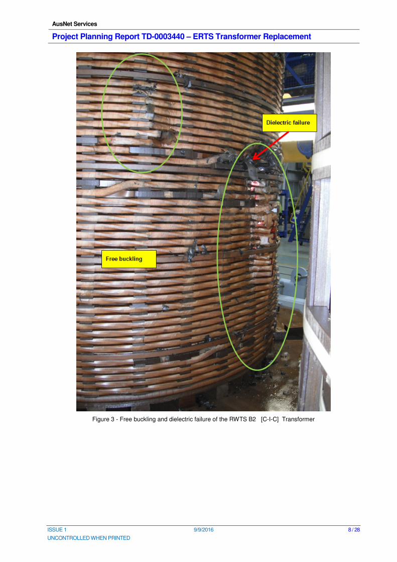
Many of the primary and secondary assets installed at the time that ERTS was established have deteriorated and are reaching the end of their technical lives. The risks associated with plant failure are increasing and these assets are becoming more difficult and expensive to maintain due to a lack of manufacturer support and a scarcity of spare parts.
An investigation of the failure of the B2 [C-I-C] transformer at Ringwood Terminal Station (RWTS) that occurred on 28 March 2016 revealed that the dielectric failure of the 66 kV winding was a consquence of previous free buckling
1. The free buckling has been identified as a design issue of all similar [C-I-C] 220/66 kV
transformers, particularly for terminal stations with high fault levels such as ERTS. ERTS is one of the connection stations with the highest fault levels given its proximity to the 500/220 kV terminal stations at Rowville and Cranbourne as well as the 220 kV supplies from the Latrobe Valley.
The free buckling and consequent dielectric failure of the RWTS B2 transformer is illustrated in Figure 3.
1 RWTS B2 Transformer Failure Report
AusNet Services
Project Planning Report TD-0003440 – ERTS Transformer Replacement
ISSUE 1 9/9/2016 8 / 28
UNCONTROLLED WHEN PRINTED
Figure 3 - Free buckling and dielectric failure of the RWTS B2 [C-I-C] Transformer
AusNet Services
Project Planning Report TD-0003440 – ERTS Transformer Replacement
ISSUE 1 9/9/2016 9 / 28
UNCONTROLLED WHEN PRINTED
5 Planning Considerations
5.1 Planning Responsibilities
The augmentation responsibility for ERTS lays with the Australian Energy Market Operator (AEMO) for the shared transmission network and with the distributors, United Energy and AusNet Electricity Services, for the transmission connection assets.
5.2 Demand
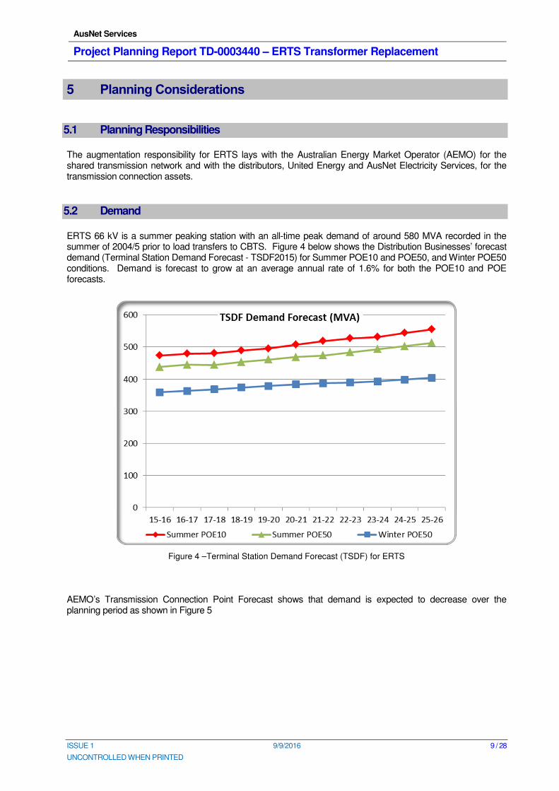
ERTS 66 kV is a summer peaking station with an all-time peak demand of around 580 MVA recorded in the summer of 2004/5 prior to load transfers to CBTS. Figure 4 below shows the Distribution Businesses’ forecast demand (Terminal Station Demand Forecast - TSDF2015) for Summer POE10 and POE50, and Winter POE50 conditions. Demand is forecast to grow at an average annual rate of 1.6% for both the POE10 and POE forecasts.
Figure 4 –Terminal Station Demand Forecast (TSDF) for ERTS
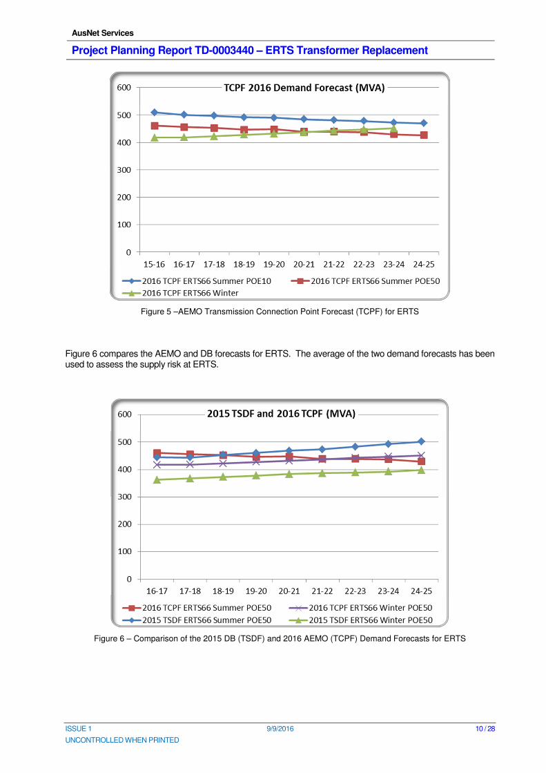
AEMO’s Transmission Connection Point Forecast shows that demand is expected to decrease over the planning period as shown in Figure 5
AusNet Services
Project Planning Report TD-0003440 – ERTS Transformer Replacement
ISSUE 1 9/9/2016 10 / 28
UNCONTROLLED WHEN PRINTED
Figure 5 –AEMO Transmission Connection Point Forecast (TCPF) for ERTS
Figure 6 compares the AEMO and DB forecasts for ERTS. The average of the two demand forecasts has been used to assess the supply risk at ERTS.
Figure 6 – Comparison of the 2015 DB (TSDF) and 2016 AEMO (TCPF) Demand Forecasts for ERTS
AusNet Services
Project Planning Report TD-0003440 – ERTS Transformer Replacement
ISSUE 1 9/9/2016 11 / 28
UNCONTROLLED WHEN PRINTED
5.3 Future Planning Requirements
Any significant asset replacements at ERTS must consider the longer term shared network and connection network development plans of other parties to ensure individual decisions will not compromise security of supply or impede economic future capacity augmentation.
AusNet Services’ redevelopment project accommodates AEMO’s and the Distribution Business’ future plans for ERTS, which include the following:
• Five 150 MVA 220/66 kV transformers;
• Fourteen 66 kV feeders;
• Four 50 MVAr 66 kV shunt capacitor banks;
AusNet Services
Project Planning Report TD-0003440 – ERTS Transformer Replacement
ISSUE 1 9/9/2016 12 / 28
UNCONTROLLED WHEN PRINTED
6 Asset Condition
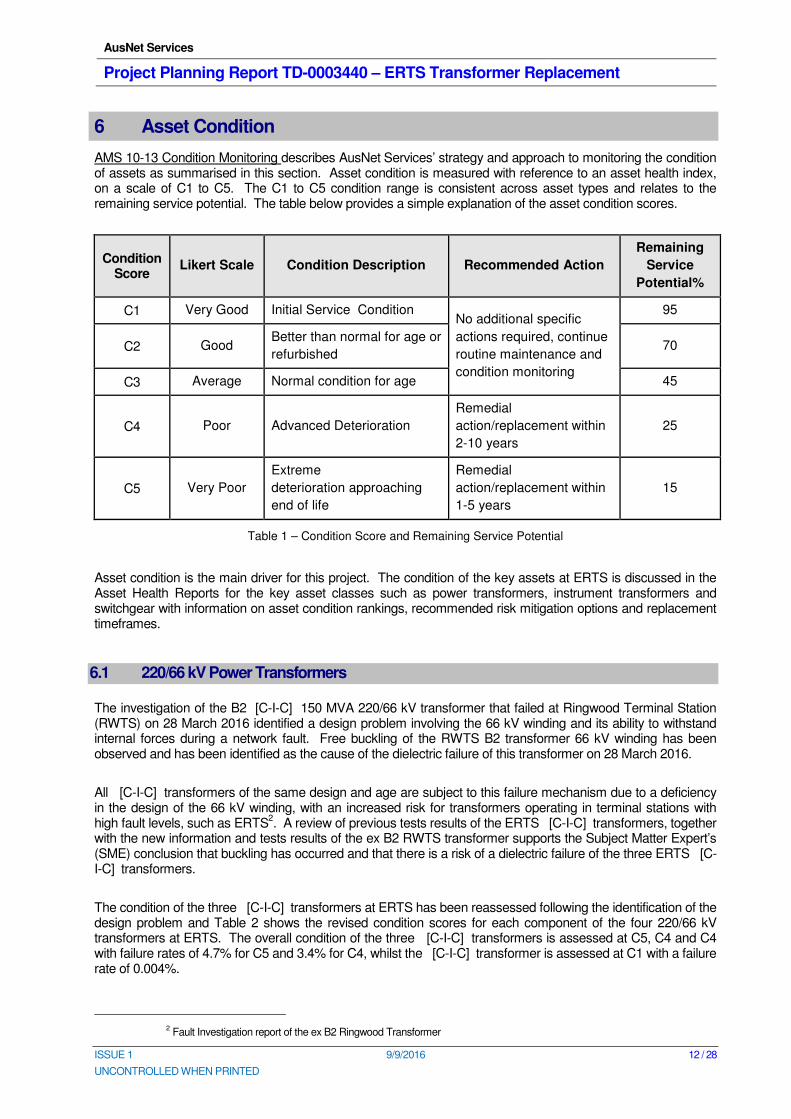
AMS 10-13 Condition Monitoring describes AusNet Services’ strategy and approach to monitoring the condition of assets as summarised in this section. Asset condition is measured with reference to an asset health index, on a scale of C1 to C5. The C1 to C5 condition range is consistent across asset types and relates to the remaining service potential. The table below provides a simple explanation of the asset condition scores.
Condition Score
Likert Scale Condition Description Recommended Action
Remaining
Service
Potential%
C1 Very Good Initial Service Condition No additional specific
actions required, continue
routine maintenance and
condition monitoring
95
C2 Good Better than normal for age or
refurbished 70
C3 Average Normal condition for age 45
C4 Poor Advanced Deterioration
Remedial
action/replacement within
2-10 years
25
C5 Very Poor
Extreme
deterioration approaching
end of life
Remedial
action/replacement within
1-5 years
15
Table 1 – Condition Score and Remaining Service Potential
Asset condition is the main driver for this project. The condition of the key assets at ERTS is discussed in the Asset Health Reports for the key asset classes such as power transformers, instrument transformers and switchgear with information on asset condition rankings, recommended risk mitigation options and replacement timeframes.
6.1 220/66 kV Power Transformers
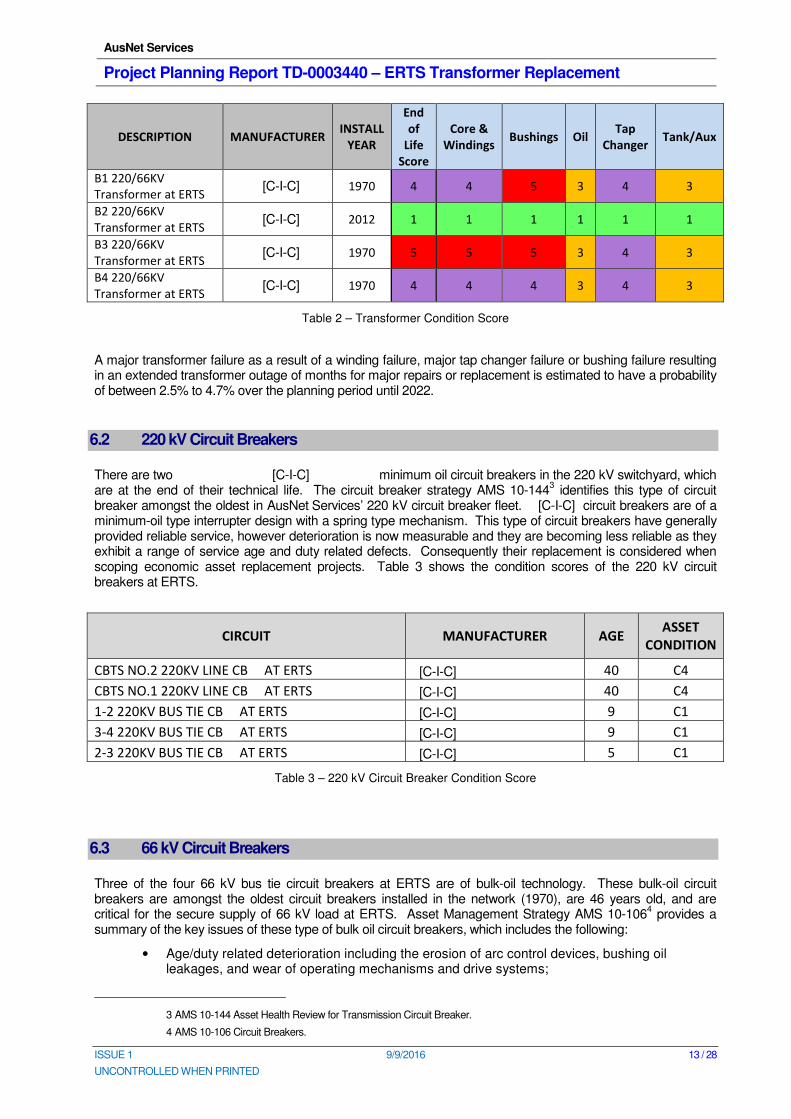
The investigation of the B2 [C-I-C] 150 MVA 220/66 kV transformer that failed at Ringwood Terminal Station (RWTS) on 28 March 2016 identified a design problem involving the 66 kV winding and its ability to withstand internal forces during a network fault. Free buckling of the RWTS B2 transformer 66 kV winding has been observed and has been identified as the cause of the dielectric failure of this transformer on 28 March 2016.
All [C-I-C] transformers of the same design and age are subject to this failure mechanism due to a deficiency in the design of the 66 kV winding, with an increased risk for transformers operating in terminal stations with high fault levels, such as ERTS
2. A review of previous tests results of the ERTS [C-I-C] transformers, together
with the new information and tests results of the ex B2 RWTS transformer supports the Subject Matter Expert’s (SME) conclusion that buckling has occurred and that there is a risk of a dielectric failure of the three ERTS [C-I-C] transformers.
The condition of the three [C-I-C] transformers at ERTS has been reassessed following the identification of the design problem and Table 2 shows the revised condition scores for each component of the four 220/66 kV transformers at ERTS. The overall condition of the three [C-I-C] transformers is assessed at C5, C4 and C4 with failure rates of 4.7% for C5 and 3.4% for C4, whilst the [C-I-C] transformer is assessed at C1 with a failure rate of 0.004%.
2 Fault Investigation report of the ex B2 Ringwood Transformer
AusNet Services
Project Planning Report TD-0003440 – ERTS Transformer Replacement
ISSUE 1 9/9/2016 13 / 28
UNCONTROLLED WHEN PRINTED
DESCRIPTION MANUFACTURER INSTALL
YEAR
End
of
Life
Score
Core &
Windings Bushings Oil
Tap
Changer Tank/Aux
B1 220/66KV
Transformer at ERTS [C-I-C] 1970 4 4 5 3 4 3
B2 220/66KV
Transformer at ERTS [C-I-C] 2012 1 1 1 1 1 1
B3 220/66KV
Transformer at ERTS [C-I-C] 1970 5 5 5 3 4 3
B4 220/66KV
Transformer at ERTS [C-I-C] 1970 4 4 4 3 4 3
Table 2 – Transformer Condition Score
A major transformer failure as a result of a winding failure, major tap changer failure or bushing failure resulting in an extended transformer outage of months for major repairs or replacement is estimated to have a probability of between 2.5% to 4.7% over the planning period until 2022.
6.2 220 kV Circuit Breakers
There are two [C-I-C] minimum oil circuit breakers in the 220 kV switchyard, which are at the end of their technical life. The circuit breaker strategy AMS 10-144
3 identifies this type of circuit
breaker amongst the oldest in AusNet Services’ 220 kV circuit breaker fleet. [C-I-C] circuit breakers are of a minimum-oil type interrupter design with a spring type mechanism. This type of circuit breakers have generally provided reliable service, however deterioration is now measurable and they are becoming less reliable as they exhibit a range of service age and duty related defects. Consequently their replacement is considered when scoping economic asset replacement projects. Table 3 shows the condition scores of the 220 kV circuit breakers at ERTS.
CIRCUIT MANUFACTURER AGE ASSET
CONDITION
CBTS NO.2 220KV LINE CB AT ERTS [C-I-C] 40 C4
CBTS NO.1 220KV LINE CB AT ERTS [C-I-C] 40 C4
1-2 220KV BUS TIE CB AT ERTS [C-I-C] 9 C1
3-4 220KV BUS TIE CB AT ERTS [C-I-C] 9 C1
2-3 220KV BUS TIE CB AT ERTS [C-I-C] 5 C1
Table 3 – 220 kV Circuit Breaker Condition Score
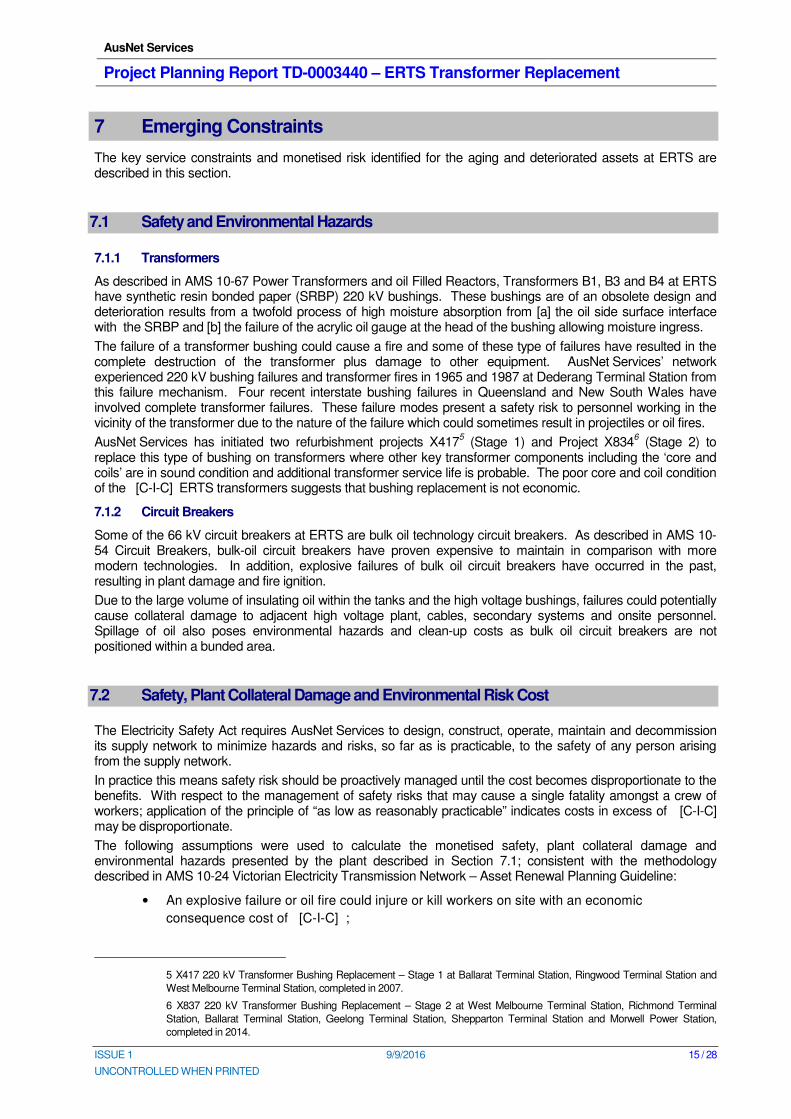
6.3 66 kV Circuit Breakers
Three of the four 66 kV bus tie circuit breakers at ERTS are of bulk-oil technology. These bulk-oil circuit breakers are amongst the oldest circuit breakers installed in the network (1970), are 46 years old, and are critical for the secure supply of 66 kV load at ERTS. Asset Management Strategy AMS 10-106
4 provides a
summary of the key issues of these type of bulk oil circuit breakers, which includes the following:
• Age/duty related deterioration including the erosion of arc control devices, bushing oil leakages, and wear of operating mechanisms and drive systems;
3 AMS 10-144 Asset Health Review for Transmission Circuit Breaker.
4 AMS 10-106 Circuit Breakers.
AusNet Services
Project Planning Report TD-0003440 – ERTS Transformer Replacement
ISSUE 1 9/9/2016 14 / 28
UNCONTROLLED WHEN PRINTED
• Limited fault level capability requiring restrictive switching configurations;
• Maintenance intensive;
• Manufacturer no-longer provides technical support or spares;
• Insufficient oil bunding.
CIRCUIT STATION INSTALL
YEAR VOLTAGE MANUFACTURER
ASSET
CONDITION
2-3 66KV BUS TIE CB AT ERTS ERTS 1970 66 [C-I-C] C4
1-4 66KV BUS TIE CB AT ERTS ERTS 1970 66 [C-I-C] C4
3-4 66KV BUS TIE CB AT ERTS ERTS 1970 66 [C-I-C] C4
Table 4 – 66 kV Circuit Breaker Condition Score
6.4 Secondary Systems
The protection and control systems at ERTS consist of varied technologies. Some of the electromechanical type relays originally installed are still in service. Over the years, protection system upgrades for specific primary assets have been necessary, resulting in the existence of first generation digital relays as well as some newer protection equipment.
The electromechanical and first generation digital relays have mal-operated in the past and have reached the end of their technical lives. The lack of serial link ports to interface with Remote Telemetry Unit (RTU) makes operation and maintenance challenging and more risky in network contingency situations. Interfacing the existing equipment with new protection systems required for new primary plant will further complicate the non-standard protection system configuration at ERTS and increase the associated operation and maintenance costs and risks.
AusNet Services
Project Planning Report TD-0003440 – ERTS Transformer Replacement
ISSUE 1 9/9/2016 15 / 28
UNCONTROLLED WHEN PRINTED
7 Emerging Constraints
The key service constraints and monetised risk identified for the aging and deteriorated assets at ERTS are described in this section.
7.1 Safety and Environmental Hazards
7.1.1 Transformers
As described in AMS 10-67 Power Transformers and oil Filled Reactors, Transformers B1, B3 and B4 at ERTS have synthetic resin bonded paper (SRBP) 220 kV bushings. These bushings are of an obsolete design and deterioration results from a twofold process of high moisture absorption from [a] the oil side surface interface with the SRBP and [b] the failure of the acrylic oil gauge at the head of the bushing allowing moisture ingress.
The failure of a transformer bushing could cause a fire and some of these type of failures have resulted in the complete destruction of the transformer plus damage to other equipment. AusNet Services’ network experienced 220 kV bushing failures and transformer fires in 1965 and 1987 at Dederang Terminal Station from this failure mechanism. Four recent interstate bushing failures in Queensland and New South Wales have involved complete transformer failures. These failure modes present a safety risk to personnel working in the vicinity of the transformer due to the nature of the failure which could sometimes result in projectiles or oil fires.
AusNet Services has initiated two refurbishment projects X4175 (Stage 1) and Project X834
6 (Stage 2) to
replace this type of bushing on transformers where other key transformer components including the ‘core and coils’ are in sound condition and additional transformer service life is probable. The poor core and coil condition of the [C-I-C] ERTS transformers suggests that bushing replacement is not economic.
7.1.2 Circuit Breakers
Some of the 66 kV circuit breakers at ERTS are bulk oil technology circuit breakers. As described in AMS 10-54 Circuit Breakers, bulk-oil circuit breakers have proven expensive to maintain in comparison with more modern technologies. In addition, explosive failures of bulk oil circuit breakers have occurred in the past, resulting in plant damage and fire ignition.
Due to the large volume of insulating oil within the tanks and the high voltage bushings, failures could potentially cause collateral damage to adjacent high voltage plant, cables, secondary systems and onsite personnel. Spillage of oil also poses environmental hazards and clean-up costs as bulk oil circuit breakers are not positioned within a bunded area.
7.2 Safety, Plant Collateral Damage and Environmental Risk Cost
The Electricity Safety Act requires AusNet Services to design, construct, operate, maintain and decommission its supply network to minimize hazards and risks, so far as is practicable, to the safety of any person arising from the supply network.
In practice this means safety risk should be proactively managed until the cost becomes disproportionate to the benefits. With respect to the management of safety risks that may cause a single fatality amongst a crew of workers; application of the principle of “as low as reasonably practicable” indicates costs in excess of [C-I-C] may be disproportionate.
The following assumptions were used to calculate the monetised safety, plant collateral damage and environmental hazards presented by the plant described in Section 7.1; consistent with the methodology described in AMS 10-24 Victorian Electricity Transmission Network – Asset Renewal Planning Guideline:
• An explosive failure or oil fire could injure or kill workers on site with an economic
consequence cost of [C-I-C] ;
5 X417 220 kV Transformer Bushing Replacement – Stage 1 at Ballarat Terminal Station, Ringwood Terminal Station and
West Melbourne Terminal Station, completed in 2007.
6 X837 220 kV Transformer Bushing Replacement – Stage 2 at West Melbourne Terminal Station, Richmond Terminal
Station, Ballarat Terminal Station, Geelong Terminal Station, Shepparton Terminal Station and Morwell Power Station,
completed in 2014.
AusNet Services
Project Planning Report TD-0003440 – ERTS Transformer Replacement
ISSUE 1 9/9/2016 16 / 28
UNCONTROLLED WHEN PRINTED
• Plant that contains large volumes of oil poses an environmental risk with an average
consequence cost of $30k per event;
• Transformer with oil that contains poly-chlorinated biphenyls (PCB) poses an environmental
risk with an average consequence cost of $100k per event;
• Plant collateral damage, including consequent supply outages, is on average $1.0 Million per
event.
The likelihood of the above hazards occurring at ERTS have been calculated from the major failure rates in the circuit breaker and power transformer reliability centred maintenance (RCM) models and the CIGRE research into the probability of explosion and fire associated with major plant failures
7.
Figure 7 shows the expected safety, plant collateral damage and environmental risk cost at ERTS based on the following risks:
• Health and safety risk due to a power transformer bushing or circuit breaker explosive failure;
• Environmental risk presented by insulating oil spillage;
• Collateral damage to adjacent plant due to catastrophic failure of plant.
[C-I-C]
Figure 7 – Expected Annual Safety, Plant Collateral Damage and Environmental Risk Cost
7.3 Reliability and Security of Supply Risk
7.3.1 220 kV Switchyard
Cranbourne (CBTS), Tyabb (TBTS) and JLA are supplied from ERTS via the two ERTS-CBTS 220 kV lines during an outage of the CBTS A1 500/220 kV transformer. The two ERTS-CBTS 220 kV lines are only single switched at ERTS and the condition of these two minimum oil circuit breakers are C4.
The entire CBTS, TBTS and JLA load of about 770 MW is at risk for a simultaneous outage of the two ERTS-CBTS 220 kV lines and CBTS A1 500/220 kV transformer.
7 Cigre Final Report of the 2004 – 2007 International Enquiry on Reliability of High Voltage Equipment.
AusNet Services
Project Planning Report TD-0003440 – ERTS Transformer Replacement
ISSUE 1 9/9/2016 17 / 28
UNCONTROLLED WHEN PRINTED
7.3.2 66 kV Switchyard
Some of the 66 kV circuit breakers at ERTS are bulk oil technology circuit breakers and the following supply risk for a failure of a 66 kV circuit breaker has been identified:
• A fault on any of the bus-tie circuit breakers could cause a short outage of two buses. All circuits may be restored after isolating the faulty circuit breaker. The result of such an event is that potentially tens of thousands of customers will experience a power outage for at least 60 minutes.
7.3.3 Expected Supply Risk
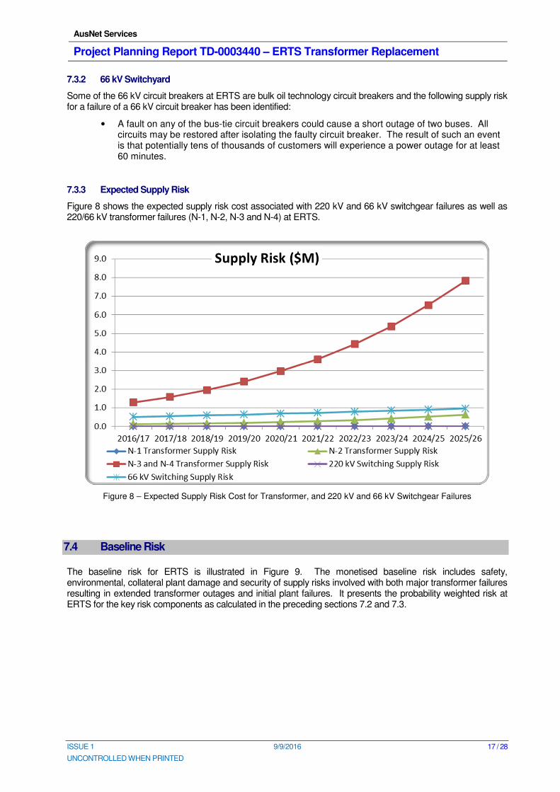
Figure 8 shows the expected supply risk cost associated with 220 kV and 66 kV switchgear failures as well as 220/66 kV transformer failures (N-1, N-2, N-3 and N-4) at ERTS.
Figure 8 – Expected Supply Risk Cost for Transformer, and 220 kV and 66 kV Switchgear Failures
7.4 Baseline Risk
The baseline risk for ERTS is illustrated in Figure 9. The monetised baseline risk includes safety, environmental, collateral plant damage and security of supply risks involved with both major transformer failures resulting in extended transformer outages and initial plant failures. It presents the probability weighted risk at ERTS for the key risk components as calculated in the preceding sections 7.2 and 7.3.
AusNet Services
Project Planning Report TD-0003440 – ERTS Transformer Replacement
ISSUE 1 9/9/2016 18 / 28
UNCONTROLLED WHEN PRINTED
[C-I-C]
Figure 9 – Baseline Risk
The baseline risk in Figure 9 is the probability weighted risk cost at ERTS of low probability, but high consequence events. It does not represent the actual societal cost of a fatality or injury, or loss of supply event. The societal cost of explosive plant failures that could injure or kill workers on site and/or critical plant outages that could result in a loss of supply from ERTS are much higher than the probability weighted monetised risk presented in Figure 9. It is estimated at [C-I-C] for a fatality, $34 M for a major failure of two transformers, which is a credible event given the design issue with the [C-I-C] Transformers, and $5 M for a circuit breaker failure. The high societal cost of plant failures, including explosive failures, suggests that options such as “Do nothing” or “Business as usual” or “Run to Failure” are not prudent asset management strategies for the asset failure risks at ERTS.
The safety and asset failure risk is forecast to progressively increase over time, predominantly due to the deteriorating condition of the transformers and switchgear. The societal cost due to plant failures at ERTS is also expected to increase as demand increases. Table 5 illustrates that significant capital investments may be economic to address the increasing base line risk at ERTS.
YEAR 2016/
17 2017/
18 2018/
19 2019/
20 2020/
21 2021/
22 2022/
23 2023/
24 2024/
25
Annual Risk Cost ($) 2.3 2.6 3.1 3.6 4.3 5.1 6.0 7.2 8.5
Present Value Risk Cost at 7.5% Discount Rate ($M)
28.9 33.4 39.5 46.4 55.4 64.9 77.3 91.8 108.6
Table 5 – Societal Risk
AusNet Services
Project Planning Report TD-0003440 – ERTS Transformer Replacement
ISSUE 1 9/9/2016 19 / 28
UNCONTROLLED WHEN PRINTED
8 Options to Address Risks
The following options have been assessed to address the increasing community risk at ERTS:
• Business as usual. This option is included in the option analysis to define the baseline risk
and to quantify the potential benefits of options that address the baseline risk;
• Non network option of embedded generation and/or demand side response;
• Run to failure and replace assets upon failure;
• Integrated replacement
• Staged replacement
9 Evaluation of Options
An economic cost-benefit assessment is used to assess and rank the economic efficiency of the non-network and network options listed in Section 8. The option analysis considers key aspects like operating and capital cost trade-offs, security of supply risk during the construction phase of the project, economic merits of each option and the future augmentation plans for ERTS.
A “Business as usual” option (Option 1) has been included in the option analysis to present the baseline risk. It illustrates whether deferment of asset replacement presents an economical option or whether the risk has reached a level that needs to be addressed during the 2017 to 2022 regulatory control period. Option 2 assesses the technical and economic merits of non-network options such as embedded generation and demand side management. Option 3 is a reactive asset replacement option. Options 4, 5 and 6 involve proactive replacement of deteriorated and failure prone equipment based on the assessed risk of an asset failure. Option 5 and 6 investigate the merit of selective asset replacement by staging the asset replacement projects rather than undertaking it as an integrated project (Option 4).
The economic analysis allows comparison of the economic cost and benefits of each option, to rank the options and to determine the economic timing of the preferred option. It quantifies the capital, operation and maintenance, and risk cost for each option. The risk cost includes safety, security of supply, environmental and collateral damage risks at ERTS. The robustness of the economic evaluation is tested for three discount rates, a sensitivity analysis of forecast plant failure rates, different demand growth scenarios and different VCR rates.
Each of the identified options for ERTS is evaluated based on the incremental benefits it delivers in the following areas:
• Reduction in health and safety risk due to plant explosive failures;
• Reduction in supply risk due to unplanned outages;
• Reduction in environmental risk due to insulating oil spillage;
• Reduction in collateral plant damage risk due to explosive plant failures;
• Reduction in operation and maintenance cost, including network losses.
9.1 Option 1: Business as Usual
The baseline risk at ERTS, as shown in Figure 9 and Table 5, defines the economic cost for the “Business as Usual” option for the period until 2024/25. It shows that the annual risk cost increases from $2.3 M to $8.5 M over the period from 2016/17 to 2024/25. The Present Value of the risk cost, assuming a flat risk profile after 2024/25, is more than $109 M
8. This suggests that a “Business as Usual” approach would not be an
economical option or a prudent management strategy for the assets at ERTS.
8 This is a conservative assumption as the risk cost is likely to increase as a result of deteriorating plant condition and
consequent failure rates.
AusNet Services
Project Planning Report TD-0003440 – ERTS Transformer Replacement
ISSUE 1 9/9/2016 20 / 28
UNCONTROLLED WHEN PRINTED
The progressive reduction in reliability of supply and increase in safety risk is inconsistent with AusNet Services’ obligations under the National Electricity Rules. Recurring asset failures is furthermore inconsistent with the requirements of the Electricity Safety Act and AusNet Services’ accepted Electricity Safety Management Scheme.
This option is used in the economic evaluation as a reference to measure the economic benefits of options that mitigate the identified risks at ERTS and to ascertain the economical time
9 for a particular option to proceed.
9.2 Option 2: Non network options of embedded generation and/or demand side response
ERTS does not have any N-1 energy at risk under 50% POE and 10% POE conditions based on the current demand forecast for the planning period. The economic benefits of non-network options are hence limited over the planning period and insufficient to warrant further analysis of this option based on typical costs for non-network options. Non network options can furthermore not address the safety risk or meet the full supply requirement of ERTS.
9.3 Option 3: Run to failure
This option involves replacing assets upon failure, which poses a significant risk to the community. The community costs that would result from applying an asset management strategy to only replace an asset after the asset has failed is as follows:
• $34 M for a major failure of two 220/66 kV transformer.
• $5 M for a circuit breaker failure.
Some of the plant (transformer bushings, 220 kV circuit breaker bushings and bulk oil 66 kV circuit breakers) at ERTS also present a safety risk should they fail explosively. This risk cannot be managed with a “run to failure” strategy as it would involve workers replacing failed equipment in a switchyard containing other equipment known to be in a deteriorated condition with a potentially hazardous mode of failure. This type of safety risk is valued at [C-I-C] as a person/s could be injured or killed following an explosive failure.
Unplanned replacement of assets after a failure occurred is furthermore an inefficient asset replacement strategy for terminal stations due to the significant higher cost (project mobilisation and demobilisation) of emergency replacements.
Recurring unplanned outages associated with a series of asset failures is inconsistent with the requirements of the Electricity Safety Act, AusNet Services’ accepted Electricity Safety Management Scheme and the National Electricity Rules. This option is hence only used for modelling purposes.
9.4 Option 4: Integrated Replacement
This option involves replacement of selected 220 kV and 66 kV circuit breakers and all three [C-I-C] 150 MVA 220/66 kV transformers based on elevated failure risks.
This option has the highest capital cost ($22.1 M), delivers significant benefits and addresses most of the risks.
9.5 Option 5: Staged Replacement – Defer Replacement of Two Transformers
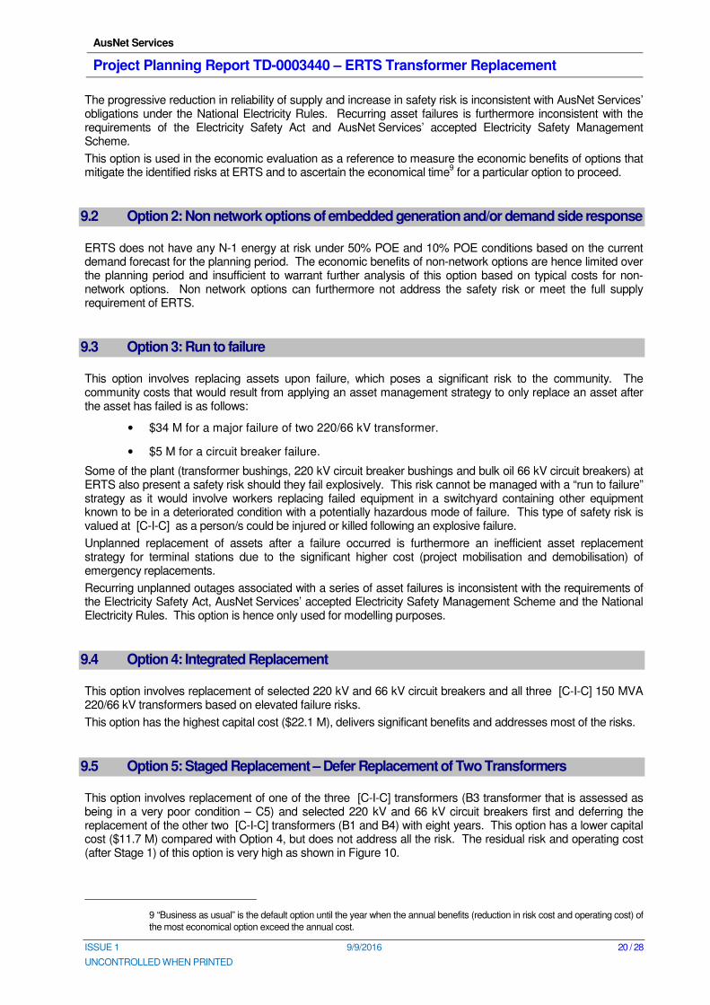
This option involves replacement of one of the three [C-I-C] transformers (B3 transformer that is assessed as being in a very poor condition – C5) and selected 220 kV and 66 kV circuit breakers first and deferring the replacement of the other two [C-I-C] transformers (B1 and B4) with eight years. This option has a lower capital cost ($11.7 M) compared with Option 4, but does not address all the risk. The residual risk and operating cost (after Stage 1) of this option is very high as shown in Figure 10.
9 “Business as usual” is the default option until the year when the annual benefits (reduction in risk cost and operating cost) of
the most economical option exceed the annual cost.
AusNet Services
Project Planning Report TD-0003440 – ERTS Transformer Replacement
ISSUE 1 9/9/2016 21 / 28
UNCONTROLLED WHEN PRINTED
Figure 10 – PV Residual Risk and Operating Cost for Option 5
9.6 Option 6: Staged Replacement – Defer Circuit Breaker Replacements
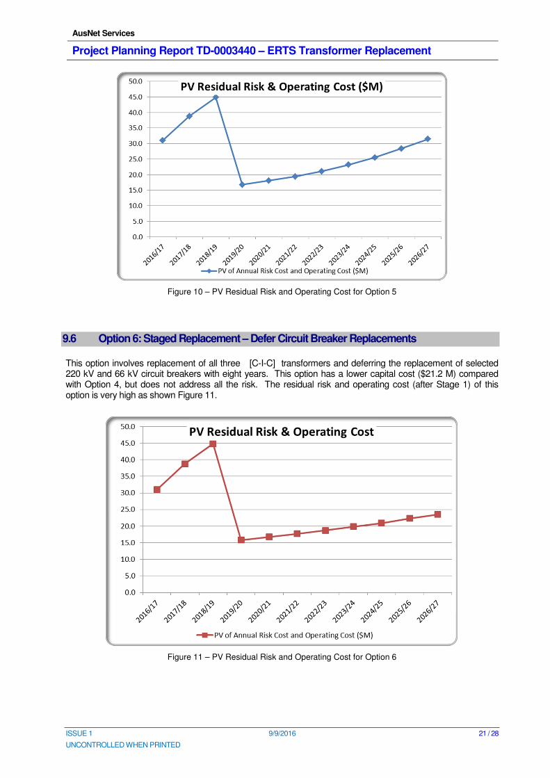
This option involves replacement of all three [C-I-C] transformers and deferring the replacement of selected 220 kV and 66 kV circuit breakers with eight years. This option has a lower capital cost ($21.2 M) compared with Option 4, but does not address all the risk. The residual risk and operating cost (after Stage 1) of this option is very high as shown Figure 11.
Figure 11 – PV Residual Risk and Operating Cost for Option 6
AusNet Services
Project Planning Report TD-0003440 – ERTS Transformer Replacement
ISSUE 1 9/9/2016 22 / 28
UNCONTROLLED WHEN PRINTED
9.7 PV Analysis
The present value cost (taking into account the total project capital cost, supply risk cost, operation and maintenance cost, safety risk cost, environment cost and plant collateral damage risk costs) is calculated for all credible options and is summarised in Table 6. This allows for the options to be ranked based on their economic merits. A real discount rate of 7.5% is used for the base case.
Options Title Assessment of Options Capital Cost
10
PV Cost (7.5% DCR)
11
1. Business as usual The baseline risk rises quickly, suggesting that a “Business as usual” approach is not sustainable.
More than
$113 M
2. Non-Network Option
This is not an economic or technically feasible solution based on the magnitude of the load and the safety risk at ERTS, which cannot be addressed with a non-network option.
Uneconomic
3. Run to failure
This option is inconsistent with AusNet Services’ accepted ESMS, the Electricity Safety Act and AusNet Services’ obligations under the NER. The baseline risk has reached a level that requires a proactive asset management strategy. Uneconomic option.
4. Integrated Replacement Address all the identified risks in a single efficient project.
$22.1 M $27.1 M
5. Staged Replacement – Defer Replacement of Two Transformers
Significant residual risk and operating cost $11.7 M $32.5 M
6. Staged Replacement – Defer Circuit Breaker Replacements
Significant residual risk and operating cost $21.2 M $35 M
Table 6 – Economic Assessment of Options – Base case assumptions
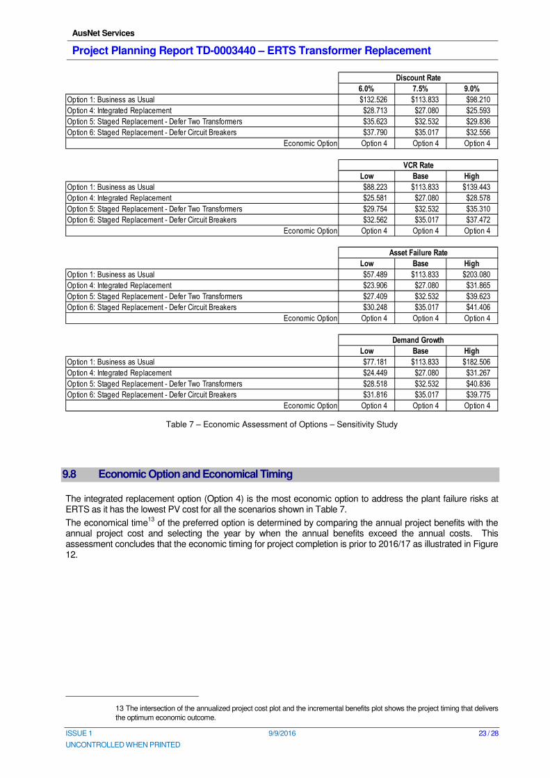
The robustness of the economic assessment is tested for different discount rates12
, asset failure rates (low case at 0.75 x base case failure rate and high case at 1.25 x base case failure rate), demand growth rates (plus and minus 15% of the base case forecast) and VCR rates (low case at 0.75 x base case and high case at 1.25 x base case) as shown in Table 7 below.
10 Total project cost expressed in real 2016 dollars.
11 Present value cost expressed in real 2016 dollars at a 7.5% discount rate.
12 AER Regulatory Investment Test for Transmission, June 2010. The present value calculations must use a commercial
discount rate appropriate for the analysis of a private enterprise investment in the electricity sector. The discount rate used
must be consistent with the cash flows being discounted. The lower boundary should be the regulated cost of capital, which
is estimated at 6% (real and pre-tax).
AusNet Services
Project Planning Report TD-0003440 – ERTS Transformer Replacement
ISSUE 1 9/9/2016 23 / 28
UNCONTROLLED WHEN PRINTED
Table 7 – Economic Assessment of Options – Sensitivity Study
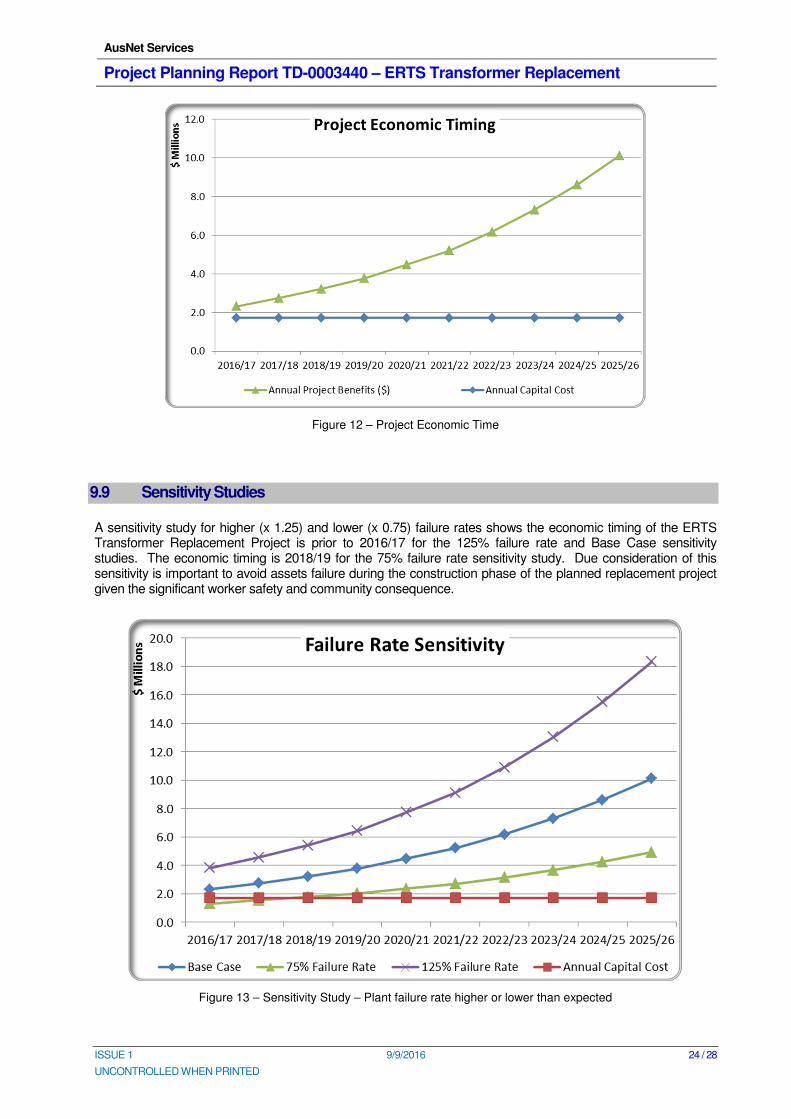
9.8 Economic Option and Economical Timing
The integrated replacement option (Option 4) is the most economic option to address the plant failure risks at ERTS as it has the lowest PV cost for all the scenarios shown in Table 7.
The economical time13
of the preferred option is determined by comparing the annual project benefits with the annual project cost and selecting the year by when the annual benefits exceed the annual costs. This assessment concludes that the economic timing for project completion is prior to 2016/17 as illustrated in Figure 12.
13 The intersection of the annualized project cost plot and the incremental benefits plot shows the project timing that delivers
the optimum economic outcome.
6.0% 7.5% 9.0%
Option 1: Business as Usual $132.526 $113.833 $98.210
Option 4: Integrated Replacement $28.713 $27.080 $25.593
Option 5: Staged Replacement - Defer Two Transformers $35.623 $32.532 $29.836
Option 6: Staged Replacement - Defer Circuit Breakers $37.790 $35.017 $32.556
Economic Option Option 4 Option 4 Option 4
Low Base High
Option 1: Business as Usual $88.223 $113.833 $139.443
Option 4: Integrated Replacement $25.581 $27.080 $28.578
Option 5: Staged Replacement - Defer Two Transformers $29.754 $32.532 $35.310
Option 6: Staged Replacement - Defer Circuit Breakers $32.562 $35.017 $37.472
Economic Option Option 4 Option 4 Option 4
Low Base High
Option 1: Business as Usual $57.489 $113.833 $203.080
Option 4: Integrated Replacement $23.906 $27.080 $31.865
Option 5: Staged Replacement - Defer Two Transformers $27.409 $32.532 $39.623
Option 6: Staged Replacement - Defer Circuit Breakers $30.248 $35.017 $41.406
Economic Option Option 4 Option 4 Option 4
Low Base High
Option 1: Business as Usual $77.181 $113.833 $182.506
Option 4: Integrated Replacement $24.449 $27.080 $31.267
Option 5: Staged Replacement - Defer Two Transformers $28.518 $32.532 $40.836
Option 6: Staged Replacement - Defer Circuit Breakers $31.816 $35.017 $39.775
Economic Option Option 4 Option 4 Option 4
Discount Rate
VCR Rate
Asset Failure Rate
Demand Growth
AusNet Services
Project Planning Report TD-0003440 – ERTS Transformer Replacement
ISSUE 1 9/9/2016 24 / 28
UNCONTROLLED WHEN PRINTED
Figure 12 – Project Economic Time
9.9 Sensitivity Studies
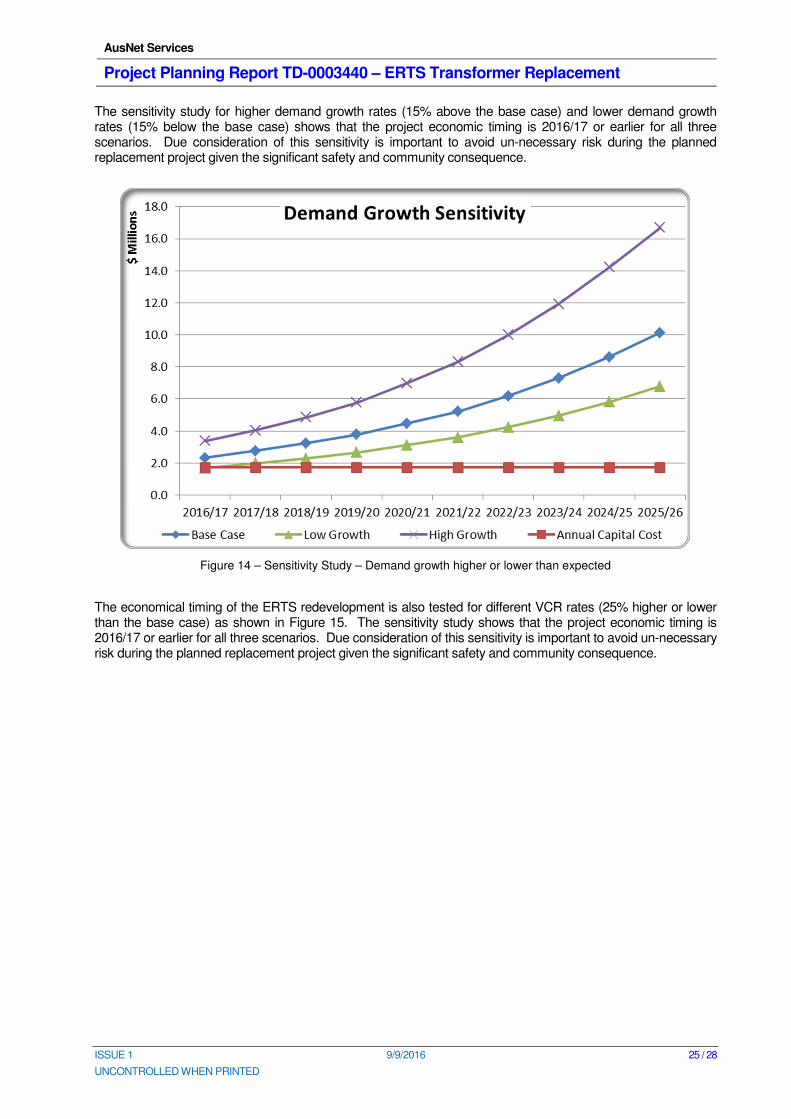
A sensitivity study for higher (x 1.25) and lower (x 0.75) failure rates shows the economic timing of the ERTS Transformer Replacement Project is prior to 2016/17 for the 125% failure rate and Base Case sensitivity studies. The economic timing is 2018/19 for the 75% failure rate sensitivity study. Due consideration of this sensitivity is important to avoid assets failure during the construction phase of the planned replacement project given the significant worker safety and community consequence.
Figure 13 – Sensitivity Study – Plant failure rate higher or lower than expected
AusNet Services
Project Planning Report TD-0003440 – ERTS Transformer Replacement
ISSUE 1 9/9/2016 25 / 28
UNCONTROLLED WHEN PRINTED
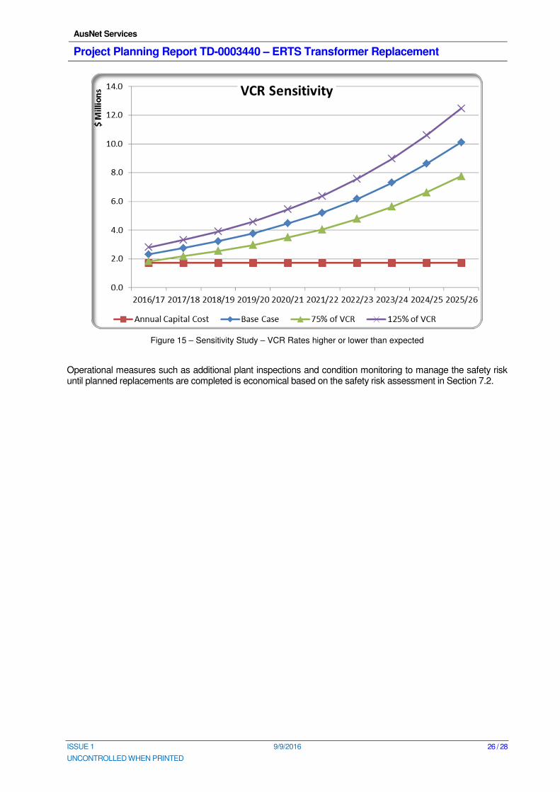
The sensitivity study for higher demand growth rates (15% above the base case) and lower demand growth rates (15% below the base case) shows that the project economic timing is 2016/17 or earlier for all three scenarios. Due consideration of this sensitivity is important to avoid un-necessary risk during the planned replacement project given the significant safety and community consequence.
Figure 14 – Sensitivity Study – Demand growth higher or lower than expected
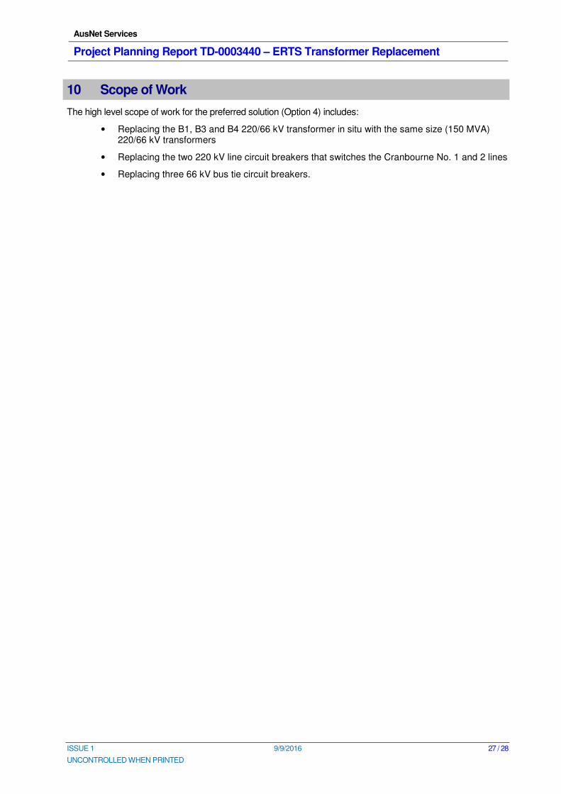
The economical timing of the ERTS redevelopment is also tested for different VCR rates (25% higher or lower than the base case) as shown in Figure 15. The sensitivity study shows that the project economic timing is 2016/17 or earlier for all three scenarios. Due consideration of this sensitivity is important to avoid un-necessary risk during the planned replacement project given the significant safety and community consequence.
AusNet Services
Project Planning Report TD-0003440 – ERTS Transformer Replacement
ISSUE 1 9/9/2016 26 / 28
UNCONTROLLED WHEN PRINTED
Figure 15 – Sensitivity Study – VCR Rates higher or lower than expected
Operational measures such as additional plant inspections and condition monitoring to manage the safety risk until planned replacements are completed is economical based on the safety risk assessment in Section 7.2.
AusNet Services
Project Planning Report TD-0003440 – ERTS Transformer Replacement
ISSUE 1 9/9/2016 27 / 28
UNCONTROLLED WHEN PRINTED
10 Scope of Work
The high level scope of work for the preferred solution (Option 4) includes:
• Replacing the B1, B3 and B4 220/66 kV transformer in situ with the same size (150 MVA) 220/66 kV transformers
• Replacing the two 220 kV line circuit breakers that switches the Cranbourne No. 1 and 2 lines
• Replacing three 66 kV bus tie circuit breakers.
AusNet Services
Project Planning Report TD-0003440 – ERTS Transformer Replacement
ISSUE 1 9/9/2016 28 / 28
UNCONTROLLED WHEN PRINTED
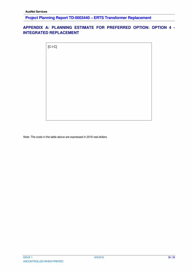
APPENDIX A: PLANNING ESTIMATE FOR PREFERRED OPTION: OPTION 4 -
INTEGRATED REPLACEMENT
[C-I-C]
Note: The costs in the table above are expressed in 2016 real dollars.