Embed Size (px)
Citation preview

AUK North 4th Well MetrologyAUK North 4th Well Metrology
THSIS - 29 Feb 2012
Presenters:
Pieter Jansen: Talisman-Energy (UK) Ltd
Greg Hammond Star Net Geomatics Ltd
AUK North 4th Well Metrology
OVERVIEW
• Project Requirements
• Existing Situation
• Development of Offshore Execution Plan
• Results
2
• Results
• Conclusions
• Future improvements
AUK North 4th Well Metrology
Project Requirements
• Execution of Laser Scan Survey of Auk North 4th Well Manifold
• Installation of new Auk North 4th Well Manifold next to existing Manifold
• Installation of 8 inch spoolpiece connecting both Manifolds
3
Note:
o Tight installation tolerances (70mm) due to short distance (12m) and relatively large
diameter pipe (8 inch).
o No installation aids remaining on existing Manifold
o Tie-in Flange on existing Manifold covered by protection panel during metrology
operations
AUK North 4th Well Metrology
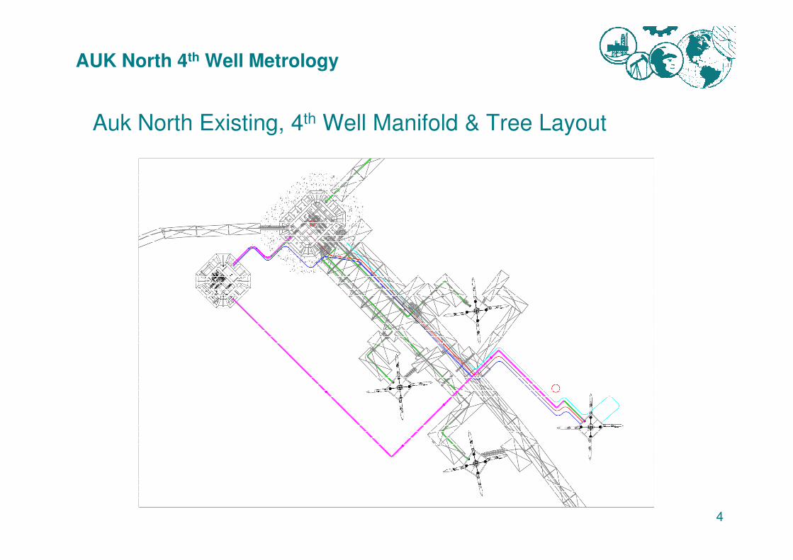
Auk North Existing, 4th Well Manifold & Tree Layout
4
AUK North 4th Well Metrology
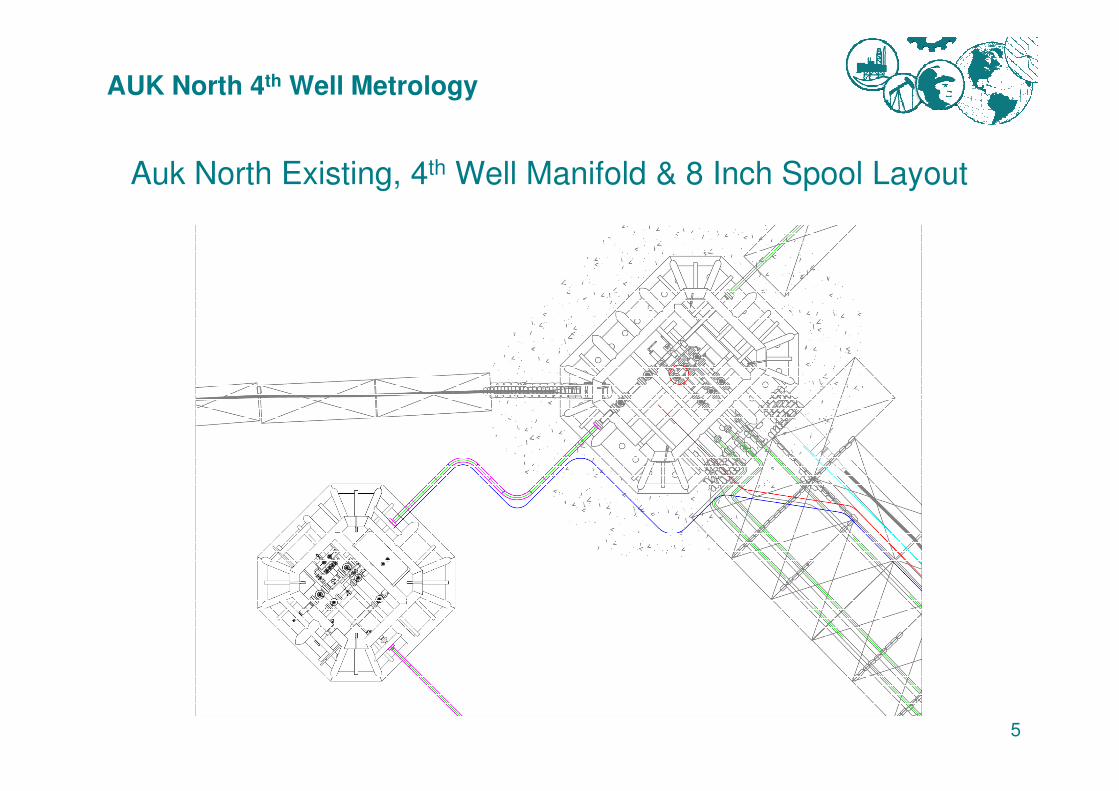
Auk North Existing, 4th Well Manifold & 8 Inch Spool Layout
5
AUK North 4th Well Metrology
Auk North Existing Infrastructure
• As-Built Information of Existing Manifoldo Existing Laser Scan XYZ Data Set
o Dimensional Control Survey Report of Existing Manifold
o Metrology Report (Existing Manifold to the three Trees)
6
<Show terrestrial data set>
AUK North 4th Well Metrology
Development of Project Execution Plan
• Construction of Spheres and Scanner Tripod with focus on deployment and recovery
• Development of standalone BlueView system applicable for ROV & Diver deployment
• Development of Scanner and Target Sphere locations
7
• Development of Scanner and Target Sphere locations
• Introducing vertical control to the Data Set
• Incorporating Processing Control, setting ground rules on how to process
• Point Cloud acquisition / processing / QC
• Assessment of Offshore Personnel Requirements
Note:
o Weekly meetings commencing from the 23rd of August until the Mobilisation mid
December
AUK North 4th Well Metrology
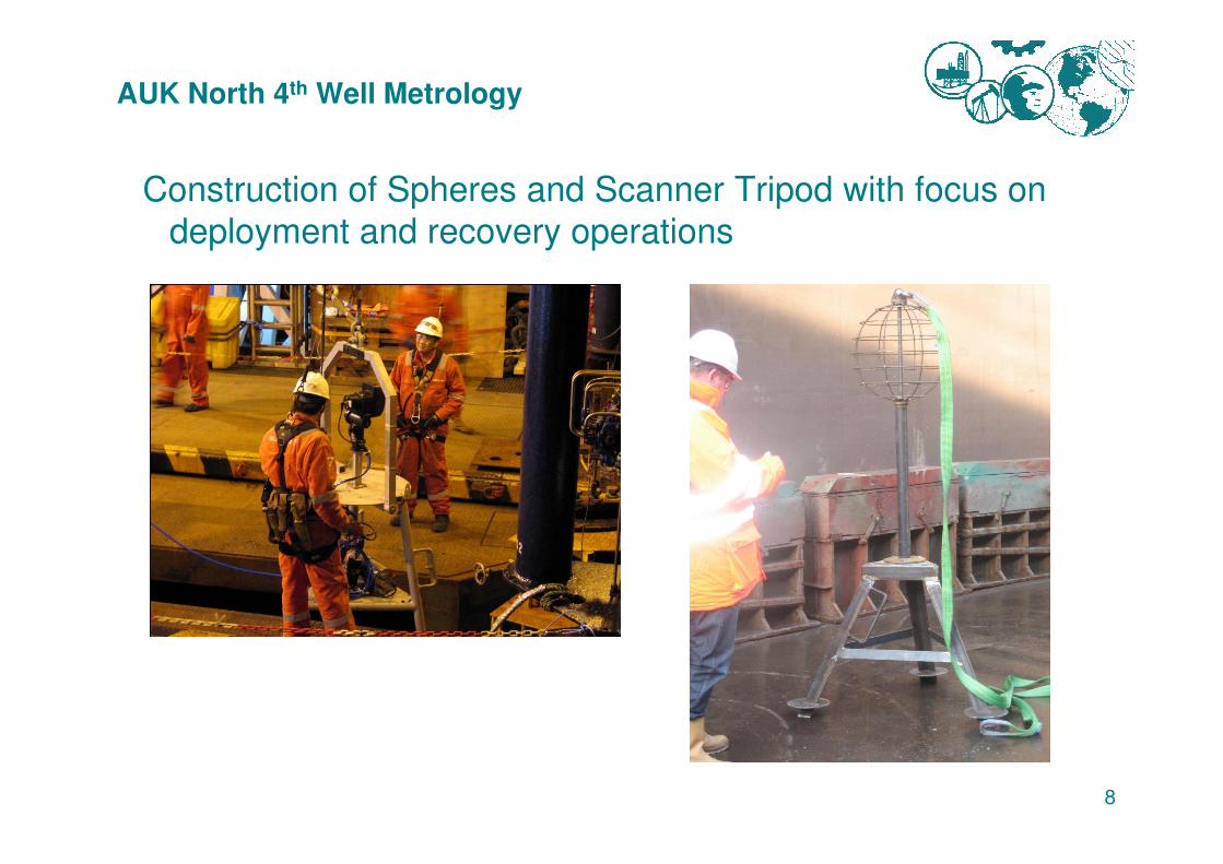
Construction of Spheres and Scanner Tripod with focus on
deployment and recovery operations
8
AUK North 4th Well Metrology
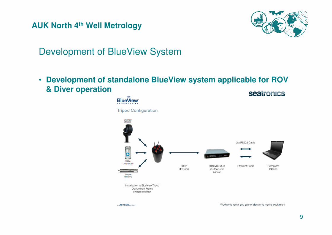
Development of BlueView System
• Development of standalone BlueView system applicable for ROV & Diver operation
9
AUK North 4th Well Metrology
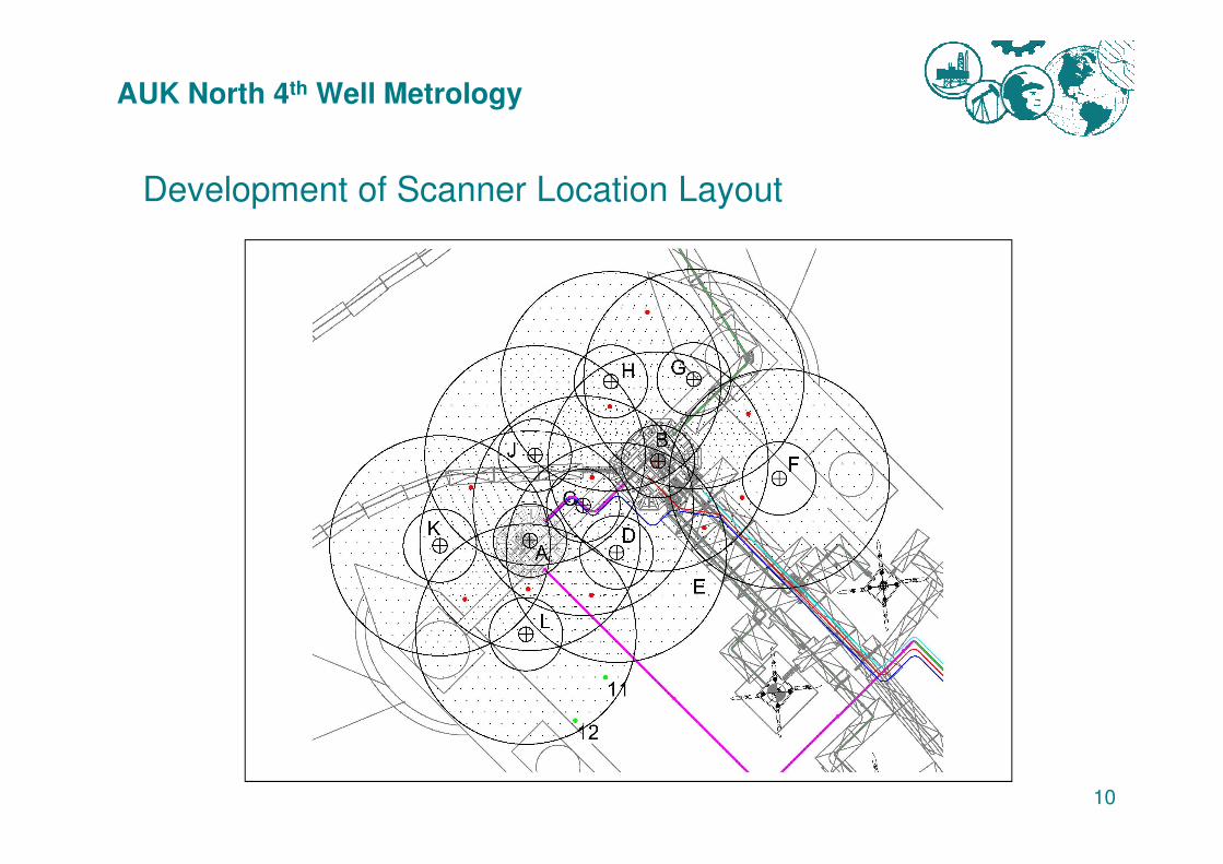
Development of Scanner Location Layout
10
AUK North 4th Well Metrology
Development of Scanner Location Layout
Taking into account the:
• Geometry of Asset, Flange and Sphere layout
• Behaviour of BlueView scanning returns
• Minimum and maximum range of BlueView scanner
11
• Minimum and maximum range of BlueView scanner
• Elevation of BlueView scanner in relationship to target
AUK North 4th Well Metrology
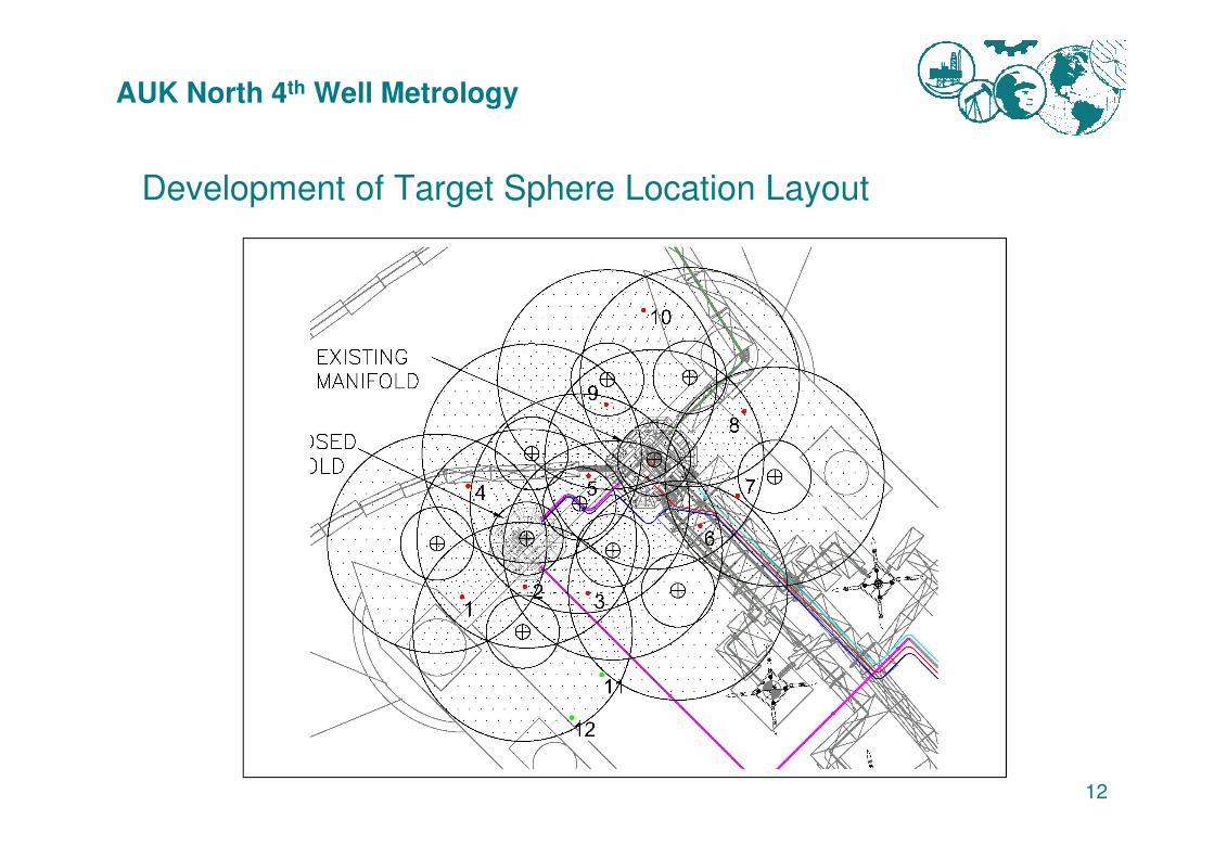
Development of Target Sphere Location Layout
12
AUK North 4th Well Metrology
Development of Target Sphere Location Layout
Taking into account the:
• Insonification of the Target Sphere by at least two BlueView scanner positions
• Geometry with the BlueView scanner positions and range in between
13
between
• Existing Infrastructure (can demand further Target Sphere locations AND further BlueView scanner positions)
• Terrain topography
AUK North 4th Well Metrology
Introducing vertical control to the Data Set
• Assigning a depth to each target sphere will provide a vertical datum to counteract any warping of the model.
• Additional depth control measures are in place; common registration objects include seabed sections which have a greater ‘warping’ restriction as the object is a plane and not a single point
14
‘warping’ restriction as the object is a plane and not a single point
AUK North 4th Well Metrology
Incorporating Processing Control
• Identification of registration objects <show>
• Assess weighting of each object
• Checking data integrity of acquired point clouds
• Data registration of point cloud subsets to registration objects
15
• Data registration of point cloud subsets to registration objects
• Network adjustment and review of parameters and registration objects to highlight problem areas within the data set
• Check results against implemented benchmarks (e.g. acoustic baseline) to quality control scaling and rotational issues
AUK North 4th Well Metrology
Offshore Personnel Requirements
• 24 hour operational cover
• 2 x Star Net Geomatics Processors
• 1 x BlueView Engineer
• 1 x Seatronics Engineer
16
• 1 x Seatronics Engineer
AUK North 4th Well Metrology
Results
• BlueView Target Sphere representation
− Effect on elevated position for scanner or target sphere
− Effect of range to Target Sphere shape
17
<show>
AUK North 4th Well Metrology
Results
• Angle of object to BlueView scanner
− Effect of striking angle of beam with object
<show>
18
AUK North 4th Well Metrology
Results
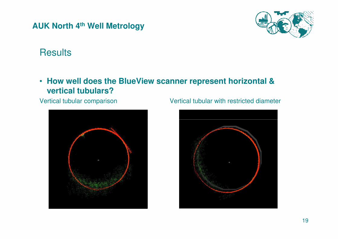
• How well does the BlueView scanner represent horizontal & vertical tubulars?
Vertical tubular comparison Vertical tubular with restricted diameter
19
AUK North 4th Well Metrology
Results
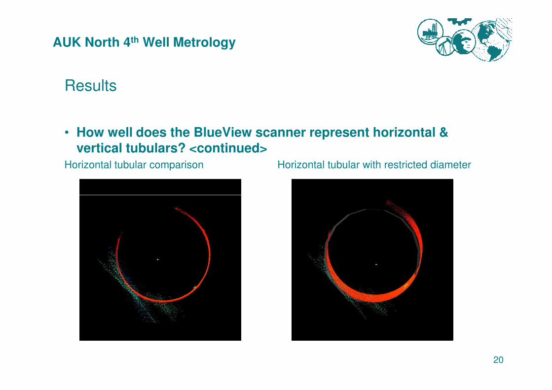
• How well does the BlueView scanner represent horizontal & vertical tubulars? <continued>
Horizontal tubular comparison Horizontal tubular with restricted diameter
20
AUK North 4th Well Metrology
Results
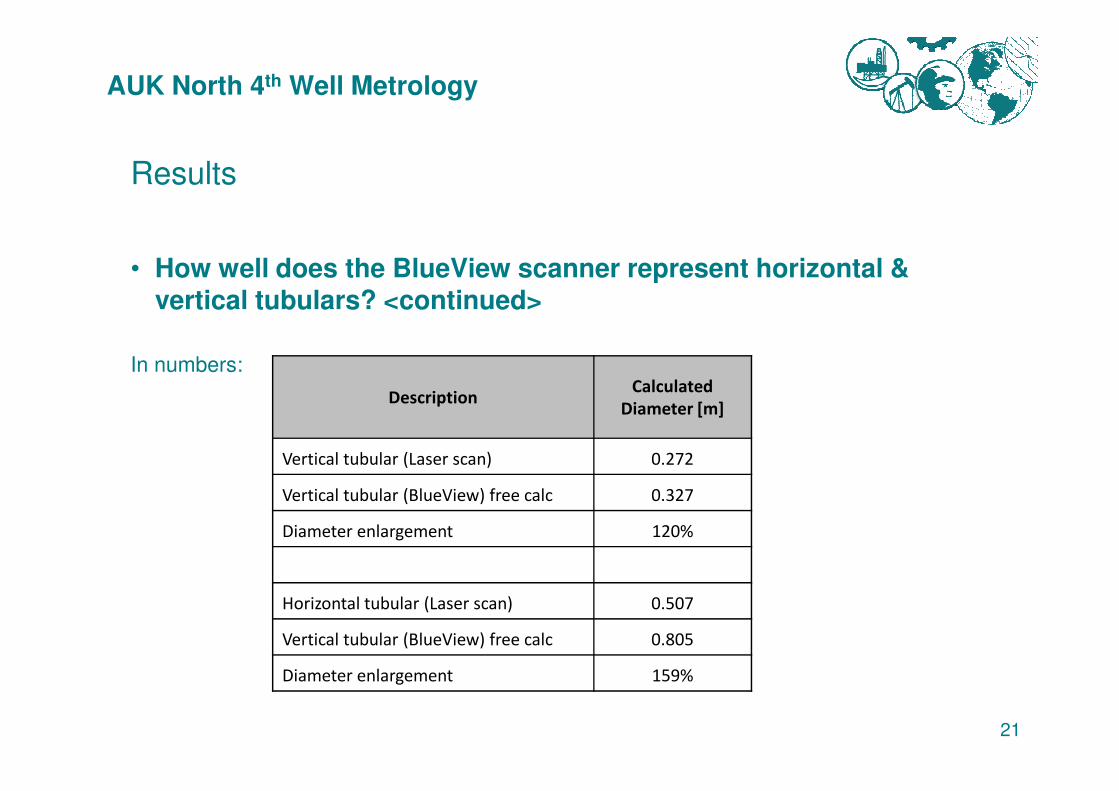
• How well does the BlueView scanner represent horizontal & vertical tubulars? <continued>
In numbers:
DescriptionCalculated
21
DescriptionCalculated
Diameter [m]
Vertical tubular (Laser scan) 0.272
Vertical tubular (BlueView) free calc 0.327
Diameter enlargement 120%
Horizontal tubular (Laser scan) 0.507
Vertical tubular (BlueView) free calc 0.805
Diameter enlargement 159%
AUK North 4th Well Metrology
Results
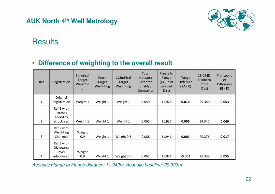
• Difference of weighting to the overall result
Ref Registration
Spherical
Target
Weightin
g
Patch
Target
Weighting
Cylindrical
Target
Weighting
Total
Network
Error for
Enabled
Contraints
Flange to
Flange
(C) (Point
to Point
Dist)
Flange
Differenc
e (A - C)
C3-C8 (D)
(Point to
Point
Dist)
Transpond
er
Difference
(B - D)
Original
22
Acoustic Flange to Flange distance: 11.942m, Acoustic baseline: 29.393m
1
Original
Registration Weight 1 Weight 1 Weight 1 0.059 11.928 0.014 29.340 0.053
2
Ref 1 with
Patches
added to
structures Weight 1 Weight 1 Weight 1 0.065 11.937 0.005 29.347 0.046
3
Ref 2 with
Weighting
Changed
Weight
0.9 Weight 1 Weight 0.5 0.088 11.941 0.001 29.376 0.017
4
Ref 3 with
Digiquartz
level
introduced
Weight
0.9 Weight 1 Weight 0.5 0.067 11.944 -0.002 29.338 0.055
AUK North 4th Well Metrology
Results
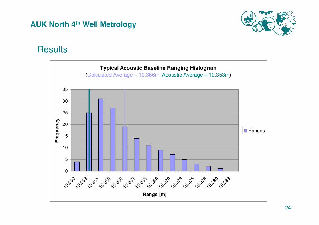
• Comparison between laser scan and BlueView point clouds of the Manifold top tubulars
− BlueView data set projects tubulars as long
− Data set therefore appears to not conform to the Gauss distribution
− Any distance based on an average (as provided by any network adjustment) will
23
− Any distance based on an average (as provided by any network adjustment) will
therefore always be long of the absolute length
AUK North 4th Well Metrology
Results
Typical Acoustic Baseline Ranging Histogram
(Calculated Average = 10.366m, Acoustic Average = 10.353m)
25
30
35
24
0
5
10
15
20
25
10.3
5010
.353
10.3
5510
.358
10.3
6010
.363
10.3
6510
.368
10.3
7010
.373
10.3
7510
.378
10.3
8010
.383
Range [m]
Fre
qu
en
cy
Ranges
AUK North 4th Well Metrology
Results
25
AUK North 4th Well Metrology
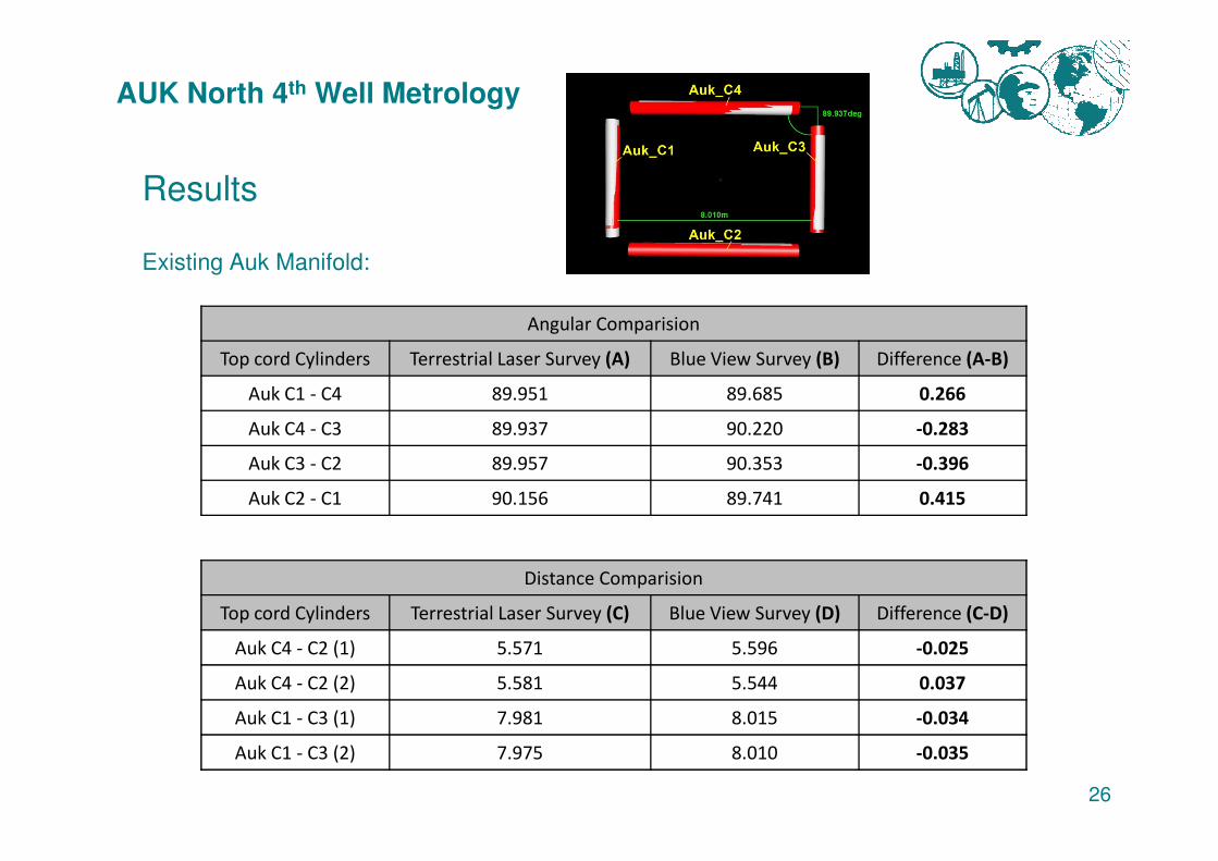
Results
Existing Auk Manifold:
Angular Comparision
Top cord Cylinders Terrestrial Laser Survey (A) Blue View Survey (B) Difference (A-B)
Auk C1 - C4 89.951 89.685 0.266
Auk C4 - C3 89.937 90.220 -0.283
26
Auk C4 - C3 89.937 90.220 -0.283
Auk C3 - C2 89.957 90.353 -0.396
Auk C2 - C1 90.156 89.741 0.415
Distance Comparision
Top cord Cylinders Terrestrial Laser Survey (C) Blue View Survey (D) Difference (C-D)
Auk C4 - C2 (1) 5.571 5.596 -0.025
Auk C4 - C2 (2) 5.581 5.544 0.037
Auk C1 - C3 (1) 7.981 8.015 -0.034
Auk C1 - C3 (2) 7.975 8.010 -0.035
AUK North 4th Well Metrology
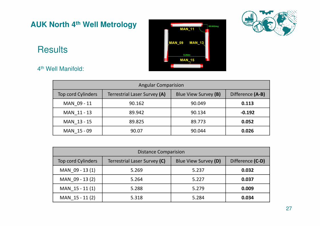
Results
4th Well Manifold:
Angular Comparision
Top cord Cylinders Terrestrial Laser Survey (A) Blue View Survey (B) Difference (A-B)
MAN_09 - 11 90.162 90.049 0.113
MAN_11 - 13 89.942 90.134 -0.192
27
MAN_11 - 13 89.942 90.134 -0.192
MAN_13 - 15 89.825 89.773 0.052
MAN_15 - 09 90.07 90.044 0.026
Distance Comparision
Top cord Cylinders Terrestrial Laser Survey (C) Blue View Survey (D) Difference (C-D)
MAN_09 - 13 (1) 5.269 5.237 0.032
MAN_09 - 13 (2) 5.264 5.227 0.037
MAN_15 - 11 (1) 5.288 5.279 0.009
MAN_15 - 11 (2) 5.318 5.284 0.034
AUK North 4th Well Metrology
Conclusions
• BlueView / Star Net solution with scanner at three primary locations inbetween the two manifolds have great correlation with LBL acoustic derived Flange to Flange position
• Registering objects and assign weighting to each class is the
28
• Registering objects and assign weighting to each class is the basis for a sound network adjustment and final result. The fine tuning will need to be perfected over time
• Shorter BlueView ranges are more accurate, as the beam width casts greater footprints at longer distances.
• Ranging comparison against known acoustic baseline is invaluable
AUK North 4th Well Metrology
Conclusions
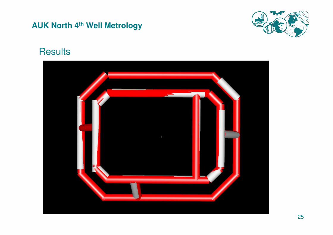
• Terrestrial laser scanning dramatically improves metrology results. The model is best fitted within the BlueView point cloud hence providing additional accuracy detail (e.g. inclination of flanges) <show>
29
• Operational execution time is dramatically reduced. Auk North 4th
well metrology took 8.5 hours (excluding bathy depth loops)
• Longitudinal profile along spoolpiece route is a natural by-product of BlueView metrology
• BlueView system meets the Measurement Accuracy required to satisfy the Auk North 8 inch spool operational expansion budget (due to temperature and pressure) of 70mm
AUK North 4th Well Metrology
Future Improvements:
• Selective area scanning
• Multiple ranging detection by (manually) setting of (time) gates
• Narrowing of beam width to improve resolution
30
AUK North 4th Well Metrology
Questions?
31
Questions?