Embed Size (px)
Citation preview
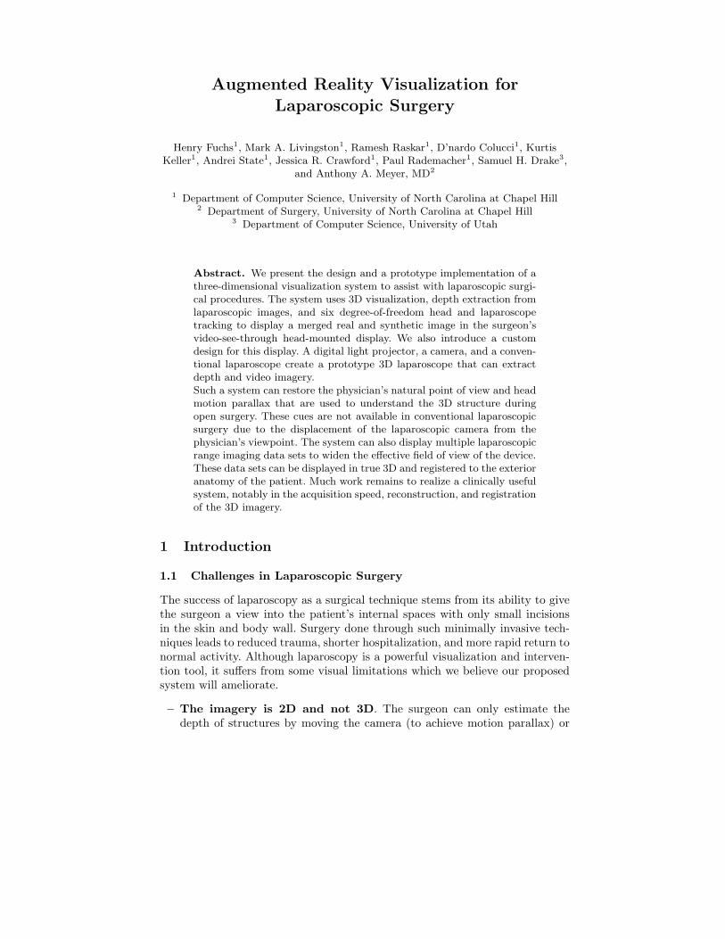
Augmented Reality Visualization for
Laparoscopic Surgery
Henry Fuchs1, Mark A. Livingston1, Ramesh Raskar1, D’nardo Colucci1, KurtisKeller1, Andrei State1, Jessica R. Crawford1, Paul Rademacher1, Samuel H. Drake3,
and Anthony A. Meyer, MD2
1 Department of Computer Science, University of North Carolina at Chapel Hill2 Department of Surgery, University of North Carolina at Chapel Hill
3 Department of Computer Science, University of Utah
Abstract. We present the design and a prototype implementation of athree-dimensional visualization system to assist with laparoscopic surgi-cal procedures. The system uses 3D visualization, depth extraction fromlaparoscopic images, and six degree-of-freedom head and laparoscopetracking to display a merged real and synthetic image in the surgeon’svideo-see-through head-mounted display. We also introduce a customdesign for this display. A digital light projector, a camera, and a conven-tional laparoscope create a prototype 3D laparoscope that can extractdepth and video imagery.Such a system can restore the physician’s natural point of view and headmotion parallax that are used to understand the 3D structure duringopen surgery. These cues are not available in conventional laparoscopicsurgery due to the displacement of the laparoscopic camera from thephysician’s viewpoint. The system can also display multiple laparoscopicrange imaging data sets to widen the effective field of view of the device.These data sets can be displayed in true 3D and registered to the exterioranatomy of the patient. Much work remains to realize a clinically usefulsystem, notably in the acquisition speed, reconstruction, and registrationof the 3D imagery.
1 Introduction
1.1 Challenges in Laparoscopic Surgery
The success of laparoscopy as a surgical technique stems from its ability to givethe surgeon a view into the patient’s internal spaces with only small incisionsin the skin and body wall. Surgery done through such minimally invasive tech-niques leads to reduced trauma, shorter hospitalization, and more rapid return tonormal activity. Although laparoscopy is a powerful visualization and interven-tion tool, it suffers from some visual limitations which we believe our proposedsystem will ameliorate.
– The imagery is 2D and not 3D. The surgeon can only estimate thedepth of structures by moving the camera (to achieve motion parallax) or
by physically probing the structures. While stereo laparoscopes and stereodisplays ameliorate this problem, they still separate the camera from thephysician’s point of view and fail to provide head-motion parallax.
– The laparoscope has a small field of view. The surgeon must frequentlyadjust the camera position and orientation, which requires skilled coordina-tion with the assistant. A surgeon may opt to operate the camera himself toreduce the discoordination of the actual view with the desired view, but thatlimits him to only one hand with which to operate. Fixed camera holders canbe used, but then the viewpoint and view direction are limited; this intro-duces risk due to the possible presence of important, vulnerable structuresoutside the viewing field.
– The procedure requires significant hand-eye coordination. The la-paroscopic camera does not generally face the direction in which the surgeonis facing. This means that the instruments’ on-screen movements will notmatch the surgeon’s hand movements. It requires experience and hand-eyecoordination for a surgeon to adjust to this disparity.
1.2 Benefits of Augmented Reality
Augmented reality (AR) refers to systems that attempt to merge computergraphics and real imagery into a single, coherent perception of an enhancedworld around the user. Emerging AR technologies have the potential to reducethe problems caused by the visual limitations of laparoscopy. The AR system candisplay the resulting 3D imagery in the proper place with respect to the exterioranatomy of the patient. By acquiring depth information and rendering true 3Dimages of the structures visible in the laparoscopic camera, the AR system givesthe physician most of the depth cues of natural vision. (Exceptions include fo-cus and visual acuity.) The display of the laparoscopic data is not limited to thecurrent viewpoint of the camera, but can include data acquired from a previouscamera location (perhaps subject to a limit on the length of time the data isconsidered “current”). Thus objects not currently within view of the camera canstill be displayed by the AR system.
We want to emphasize that this technology is fundamentally different thancoupling a stereo laparoscope with a stereo display system. AR systems allowthe surgeon to view the medical imagery from the natural viewpoint, use head-induced motion parallax (instead of hand-eye coordination and camera-inducedmotion parallax), allow the medical imagery to be visually aligned to the exterioranatomy of the patient, and incorporate proprioceptive (body-relative) cues.
The lack of depth perception in laparoscopic surgery might limit delicatedissection or suturing [Durrani95]. An AR display presents objects in correctperspective depth, assuming that the geometry has been accurately acquired.With an AR guidance system, a laparoscopic surgeon might be able to view theperitoneal cavity from any angle merely by moving his head, without movingthe endoscopic camera. AR may be able to free the surgeon from the technicallimitations of the imaging and visualization methods, recapturing much of thephysical simplicity and direct visualization characteristic of open surgery.
2 Previous Work
2.1 Medical Augmented Reality Systems
The first medical application of AR was to neurosurgery [Kelly86]. Similar sys-tems [Lorensen93,Grimson95] have been developed independently. AR has alsobeen applied to otolaryngology [Edwards95]. These applications demand less ofthe AR system than laparoscopy for four reasons. The surgical field is small, thepatient doesn’t move, the view into the patient is from a single viewpoint andview direction, and this viewpoint is external to the patient (e.g. already suit-able for a hand-eye coordination). This simplifies the difficult task of buildingan enhanced visualization system.
Our research on medical applications of AR has until recently concentratedon ultrasound-guided procedures such as fetal examination [Bajura92,State94]and breast biopsy [Fuchs96,State96]. In the latter system, the ultrasound datais captured as a video stream and registered to the patient in real time. Thephysician’s head must be tracked in order to view the dynamic data from anydirection. We calibrate the location of the ultrasound data with respect to theprobe geometry and track the probe location. These two tasks enable registrationof multiple discrete slices to each other and registration of the ultrasound dataset to the patient. A virtual pit [Bajura92] within the patient’s body providesproper occlusion cues for the registered ultrasound data. We base our proposedsystem to aid laparoscopic surgery on this system.
2.2 Depth Extraction
The major new technology needed for laparoscopic visualization is acquisitionof the depth map associated with the image from the laparoscopic camera. De-termination of 3D scene structure from a sequence of 2D images is one of theclassic problems in computer vision [Faugeras93]. There are numerous techniquesfor computing 3D structure, including cues from motion, stereo, shading, focus,defocus, contours, and structured light. We chose structured light for severalreasons. It is an efficient and direct computation. It is as robust to shading vari-ations and repeating patterns as other methods (although no method is immuneto some features, such as specular highlights) and can be dynamically tuned toincrease robustness. It offers a large depth range and allows us to trade speedfor spatial resolution in the acquisition.
Structured light has long been used in computer vision to acquire depthinformation [Besl89,Daley95]. A variety of patterns have been tried: points, lines,multiple points, multiple lines, grids, circles, cross-hairs, thick stripes, binary-coded patterns, color-coded stripes, and random textures. Pseudo-random binaryarrays [Lavoie96] are grids with recognizable points based on a pattern of “large”and “small” intersection points. We initially chose binary-coded patterns, butswitched to lines since our prototype system cannot acquire images of the patternfast enough to support depth extraction from dynamic scenes. (See Section 7 forour future plans regarding this issue.)
3 Hardware Configuration
There are four primary hardware components to our system. Three are thestandard tools of AR systems: an image generation platform, a set of trackingsystems, and a see-through head-mounted display (HMD) that allows the userto see the real environment. The fourth component required for this applicationis a 3D laparoscope that can acquire both color and range data. As noted above,we have previously applied AR to in-place visualization of ultrasound imagery.The current system is similar to that system [State96,Fuchs96].
3.1 See-Through Head-Mounted Display
We believe that the depth cue of occlusion is vital to the physician in determiningthe 3D structure of the medical imagery. Video-see-through (VST) displays offerthe possibility of complete occlusion of the real world by the computer-generatedimagery, which in this case is the medical image data. (The other option, optical-see-through displays, cannot achieve complete occlusion of the real world.) Beingunaware of any commercially available VST HMDs, we initially built a simpleprototype VST HMD from commercial components [State96]. This device hadnumerous limitations [Fuchs96]. In response to our experience with that device,we designed and implemented a new VST HMD, which is described in Section 4.
3.2 Image Generation
Having chosen to build a VST system, we needed an image generation platformcapable of acquiring multiple, real-time video streams. We use an Onyx Infi-nite Reality system from Silicon Graphics, Inc. equipped with a Sirius VideoCapturetmunit. This loads video imagery from the cameras on the VST HMDdirectly into the frame buffer. We augment this background image with a reg-istered model of the patient’s skin acquired during system calibration [State96].We then render the synthetic imagery in the usual manner for 3D computergraphics. At pixels for which there is depth associated with the video imagery(e.g. the patient’s skin), the depth of the synthetic imagery is compared. Thesynthetic imagery is painted only if it is closer. This properly resolves occlusionbetween the synthetic imagery and the patient’s skin.
The video output capabilities of the Infinite Reality architecture allow usto output two VGA signals to the displays in the HMD and a high resolutionvideo signal, which contains a user interface and is displayed on a conventionalmonitor. The system architecture is depicted graphically in Figure ??.
3.3 Tracking Systems
We use UNC’s optoelectronic ceiling tracker [Welch96] for tracking the physi-cian’s head. It offers a high update rate, a high degree of accuracy, and a largerange of head positions and orientations. The large range allows the physician
to move freely around the patient and to examine the patient from many view-points. We track the laparoscope with the FlashPointtm 5000 [IGT97] opticaltracker from Image-Guided Technologies, Inc. It also offers high accuracy, butover a small range. Since the laparoscope does not move much, this is suitable forour system. Its accuracy enables the registration between multiple laparoscopedata images and between the laparoscopic data set and the patient.
3.4 3D Laparoscope
To properly display the 3D structure, the laparoscope must acquire depth infor-mation. To properly display the visual texture (e.g. color, shading), the laparo-scope must acquire the usual 2D color video image. We can then texture theresulting 3D mesh with the color data. We designed a custom device, describedin Section 5. The device requires input of structured light images and outputs im-ages suitable for depth and color processing. We off-load the processing of theseimage streams to a Silicon Graphics O2, which outputs the structured light andacquires the camera video. After simple image processing, the O2 sends to theOnyx a list of lit pixels, from which the depth is computed.
4 Video-See-Through Head-Mounted Display
We use a miniature HMD custom-designed at the computer science laboratoriesat the University of North Carolina and University of Utah. This VST HMDhas a miniature video camera mounted in each display optic in front of eacheye (Figure ??). A pair of mirrors place the apparent centroid of the camera inthe same location as the center of the eye when the HMD is properly fitted tothe user. A 640 × 480 LCD mounted in the eyepiece is viewed through a prismassembly which folds the optical path within a small cube. This design reducesthe problem of unequal depths for the user’s visual and tactile senses. The HMDhas two eyepieces mounted on a horizontal bar which provides one degree oftranslational freedom and one degree of rotational freedom. This allows the userto adjust the inter-camera distance and the convergence angle. The entire frontbar can be moved out of the way (Figure ??). The complete HMD weighs onlytwelve ounces, compared to six pounds for our initial prototype.
5 3D Laparoscope
To extract 3D shape, we added a structured light to a conventional laparoscope.Our “structure” is a vertical line in the image plane of the projector. We calibratethe device by building a table of depth values, then use a simple extractionalgorithm which interpolates through the table. This technique has performedwell on simple geometry such as scenes with little or none of the surface occludedfrom the projector’s view. It has not yet performed well on topologically complexmodels that have great discontinuities in depth, highly specular reflections, lowreflectance, or large patches of surfaces hidden from the projector’s viewpoint.
5.1 3D Laparoscope Design
The structured light 3D laparoscope design (Figure ??) uses a conventional la-paroscope in a rather unique way. Instead of being the both the illuminationsource and imaging device, it is only a projector—but of structured light pat-terns. A digital micromirror device [Hornbeck95] projector displays its imagethrough a custom optic and through a standard laparoscope, projecting its imageinside the patient. The image is the dynamic, calibrated structured light image.Alongside the projecting laparoscope is a miniature video camera mounted in ametal tube similar to a second laparoscope. This camera observes the structuredlight pattern on the scene and sends the image to the host. The two laparoscopesare mounted a fixed distance from each other for accurate and repeatable depthextraction.
5.2 Depth Calibration and Extraction
We measure the reflected light pattern for a set of known depths and store theresults in a table. By imaging each potential light stripe from the projector ontoa flat grid at a known depth, we can determine the 3D location of the pointat each pixel in the camera image. With several depths, we can build a tableindexed by the column number from the projector and the u and v-coordinateson the camera image plane. At each cell in the table is a 3D point. Simplethresholding determines which pixels in the camera image are illuminated bythe light stripe. We find the centroid of the biggest and brightest 1D blob oneach camera scanline. The 3D location of this point is interpolated from thetable.
6 Experiments and Results
We have implemented two versions of this system. In the first prototype, weacquired depth via manual digitization. This implies a pre-operative acquisitionof the 3D structure of the internal anatomy. Guided by real-time color imagestextured onto the 3D mesh, the surgeon (Meyer) successfully pierced a smallfoam target inside the abdominal cavity of a life-sized human model (Figures ??
and ??). This experiment showed the potential of our proposed paradigm forlaparoscopic surgery. It also emphasized the importance of extracting the internal3D structure in real time. For example, a manipulator inserted into the abdomenwas severely distorted onto the surface mesh instead of appearing to be abovethe surface because only imagery was acquired in real time, not the 3D structure.
The second experiment was recently conducted with a system that imple-ments interactive depth extraction. The results of this system have been promis-ing (Figure ??). The augmented images shown to a moving HMD user clearlypresent the 3D structure. The computer-generated imagery of the internal struc-ture is visually aligned with the exterior patient anatomy.
7 Discussion
We are currently focusing on three issues. First, depth extraction is slow dueto inconsistent delay between commanding the projector to emit a pattern andreceiving the image of the pattern from the camera. (This is more complex thansynchronizing the vertical refresh.) Second, gathering multiple views is difficultdue to the rigid connection between the (bulky) projector and the laparoscope.Third, multiple depth images are misregistered due to poor depth calibration.
Our current solution to the slow speed is to wait for the delay to expire. Weare developing a tighter, coupled control of the camera and projector. When thisis in place, we will be able to extract new data at every frame. We can also returnto using binary-coded patterns as the structured light. These algorithmic andhardware improvements, along with a higher-speed projector and camera, willenable us to incrementally update an entire range image with each new videoimage of the pattern, thus extracting depth from a larger area of the surgical fieldat each time step. We will investigate methods of adaptive depth acquisition toincrease accuracy and resolution in regions of particular concern to the surgeon.For gathering multiple views, we are working with fiberoptic cables and miniaturecameras and displays to make the 3D laparoscope smaller and easier to maneuverinto multiple positions. By improving depth calibration and merging multiplerange images [Turk94], we hope to provide a more complete view of the interiorscene than visible from a single laparoscope location, approaching the wide-areasurgical field in open surgery. In the future, by registering pre-operative images(e.g. MRI or CT), surgical planning data, and intra-operative (e.g. ultrasound),we hope to provide a more comprehensive visualization of the surgical field thaneven open surgery.
We postulate that viewing laparoscopic images with our augmented realityparadigm, from outside the body, as if there were an opening into the patient, willbe more intuitive than observing laparoscopic imagery on a video monitor or evenviewing images from stereo laparoscopes on a stereo video monitor. We expectthat the physician will still choose to move the laparoscope frequently (closerto view structures of interest or farther away to view of the entire interventionsite), but with our system such movements will not cause confusing changes inthe viewpoint requiring mental adaptation. Rather they will change the levelof detail and update the visualization of structures that become visible to thelaparoscope. We expect the physician’s use of the laparoscope to be somewhatakin to exploring a dark room with a flashlight, with the added benefit of visualpersistence of the regions of the scene that were previously illuminated.
We hope that our proposed system will eventually offer the following specificbenefits. It could reduce the average time for the procedures (benefiting bothphysician and patient), reduce training time for physicians to learn these pro-cedures, increase accuracy in the procedures due to better understanding of thestructures in question and better hand-eye coordination, reduce trauma to thepatient through shorter and more accurate procedures, and increase availabilityof the procedures due to ease of performing them.
References
[Bajura92] Bajura, M., Fuchs, H., and Ohbuchi, R. (1992). Merging virtual objectswith the real world: Seeing ultrasound imagery within the patient. In ComputerGraphics (SIGGRAPH ’92 Proceedings), volume 26, pages 203–210.
[Besl89] Besl, P. J. (1989). Active optical range imaging sensors. In Advances inMachine Vision, pages 1–63. Springer-Verlag.
[Daley95] Daley, R. C., Hassebrook, L. G., Stanley C. Tungate, J., Jones, J. M.,Reisig, H. T., Reed, T. A., Williams, B. K., Daugherty, J. S., and Bond, M. (1995).Topographical analysis with time modulated structured light. SPIE Proceedings,2488(5):396–407.
[Durrani95] Durrani, A. F. and Preminger, G. M. (1995). Three-dimensional videoimaging for endoscopic surgery. Computers in Biological Medicine, 25(2):237–247.
[Edwards95] Edwards, P., Hawkes, D., Hill, D., Jewell, D., Spink, R., Strong, A., andGleeson, M. (1996). Augmentation of reality in the stereo operating microscope forotolaryngology and neurosurgical guidance. Journal of Image-Guided Surgery, 1(3).
[Faugeras93] Faugeras, O. (1993). Three-Dimensional Computer Vision: A GeometricViewpoint. MIT Press.
[Fuchs96] Fuchs, H., State, A., Pisano MD, E. D., Garrett, W. F., Hirota, G., Liv-ingston, M. A., Whitton, M. C., and Pizer, S. M. (1996). Towards performingultrasound-guided needle biopsies from within a head-mounted display. In Visu-alization in Biomedical Computing 1996, pages 591–600.
[Grimson95] Grimson, W., Ettinger, G., White, S., Gleason, P., Lozano-Perez, T.,Wells III, W., and Kikinis, R. (1995). Evaluating and validating an automated regis-tration system for enhanced reality visualization in surgery. In Proceedings of Com-puter Vision, Virtual Reality, and Robotics in Medicine ’95 (CVRMed ’95),.
[Hornbeck95] Hornbeck, L. J. (1995). Digital light processing and MEMS: Timelyconvergence for a bright future. In Micromachining and Microfabrication ’95.
[IGT97] Image-Guided Technologies, Inc. (1997). FlashPointtmModel 5000 3D Local-izer User’s & Programmer’s Manual. Boulder, CO.
[Kelly86] Kelly MD, P. J., Kall, B., and Goerss, S. (1986). Computer-assisted stereo-taxic resection of intra-axial brain neoplasms. Journal of Neurosurgery, 64:427–439.
[Lavoie96] Lavoie, P., Ionescu, D., and Petriu, E. M. (1996). 3-D object model recoveryfrom 2-D images using structured light. In IEEE Instrument Measurement TechnologyConference, pages 377–382.
[Lorensen93] Lorensen, W., Cline, H., Nafis, C., Kikinis, R., Altobelli, D., and Glea-son, L. (1993). Enhancing reality in the operating room. In Proceedings of IEEEVisualization ’93.
[State94] State, A., Chen, D. T., Tector, C., Brandt, A., Chen, H., Ohbuchi, R., Bajura,M., and Fuchs, H. (1994). Case study: Observing a volume-rendered fetus within apregnant patient. In Proceedings of IEEE Visualization ’94, pages 364–368.
[State96] State, A., Livingston, M. A., Hirota, G., Garrett, W. F., Whitton, M. C., andFuchs, H. (1996). Technologies for augmented-reality systems: Realizing ultrasound-guided needle biopsies. In SIGGRAPH 96 Conference Proceedings, Annual Confer-ence Series, pages 439–446. ACM SIGGRAPH, Addison Wesley.
[Turk94] Turk, G. and Levoy, M. (1994). Zippered polygon meshes from range im-ages. In Proceedings of SIGGRAPH ’94, Computer Graphics Proceedings, AnnualConference Series, pages 311–318.
[Welch96] Welch, G. F. (1996). Single-Constraint-At-A-Time Tracking. Ph.D. Disser-tation, University of North Carolina at Chapel Hill.
Sirius
SGI
ONYX
Infinite
Reality
L R
PatientInterior
L
R
videomux
Cameras
OpticalEmitters
Optical Tracker(FlashPoint)
SGI O2
Cam
Pro
PartialDepth
Video Images
Structured Light
UNC Optical Ceiling Tracker
HiBall
Color
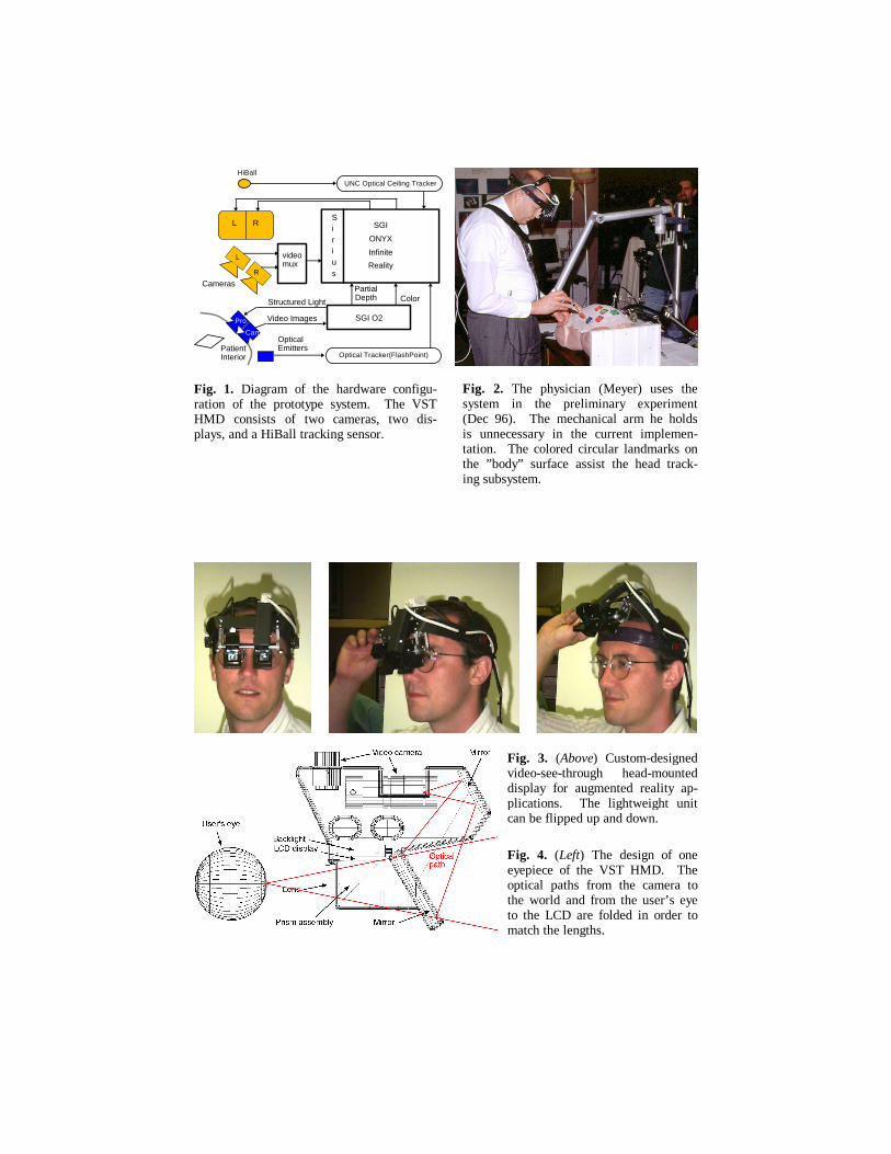
Fig. 1. Diagram of the hardware configu-ration of the prototype system. The VST HMD consists of two cameras, two dis- plays, and a HiBall tracking sensor.
Fig. 2. The physician (Meyer) uses the system in the preliminary experiment (Dec 96). The mechanical arm he holds is unnecessary in the current implemen-tation. The colored circular landmarks on the ”body” surface assist the head track- ing subsystem.
Fig. 3. (Above) Custom-designed video-see-through head-mounted display for augmented reality ap-plications. The lightweight unit can be flipped up and down.
Fig. 4. (Left) The design of one eyepiece of the VST HMD. The optical paths from the camera to the world and from the user’s eye to the LCD are folded in order to match the lengths.
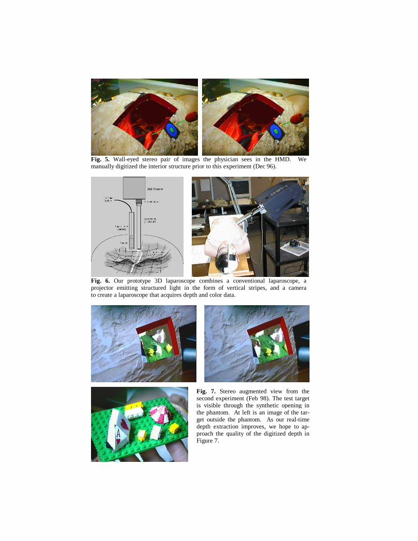
Fig. 5. Wall-eyed stereo pair of images the physician sees in the HMD. We manually digitized the interior structure prior to this experiment (Dec 96).
Fig. 6. Our prototype 3D laparoscope combines a conventional laparoscope, a projector emitting structured light in the form of vertical stripes, and a camera to create a laparoscope that acquires depth and color data.
Fig. 7. Stereo augmented view from the second experiment (Feb 98). The test target is visible through the synthetic opening in the phantom. At left is an image of the tar-get outside the phantom. As our real-time depth extraction improves, we hope to ap-proach the quality of the digitized depth in Figure 7.