Embed Size (px)
Citation preview
32
IX. Évfolyam 3. szám - 2014. szeptember
Lukács Lóránd [email protected]
AUGMENTED REALITY FOR AIRCRAFT CONTROL
Abstract
The paper presents a low computational cost system engineering solution which
can be used for the control and navigation of airplanes in low visibility when
Instrumental Flight Rules apply. The application presented in the paper uses the
orientation and navigation information of a glider aircraft superimposed on images
acquired with a wide angle lens camera during flight. Using this method of
displaying data, the crucial information needed for aircraft control such as
orientation, heading, airspeed, vertical speed, altitude, angle of attack and slip
angle of the aircraft can be viewed by pilots without requiring them to lose sight of
their visual viewpoints. The paper emphasizes on determining the correct position
of the main visual elements on the image plane required for maintaining the desired
heading and attitude of the aircraft. The developed method can also be applied for
UAVs controlled via video link.
A tanulmány légi járművek irányításához szükséges alacsony számítási költségekkel
járó megoldást mutat be, ami alkalmazható rossz látási körülmények közötti
vezérlésénél vagy olyan esetekben, amikor műszerrepülési helyzetek lépnek fel. A
bemutatott alkalmazás egy vitorlázó repülőgép példáján becsült orientációs és
navigációs adatokat helyez széles látószögű videó kamera által rögzített képekre
repülés közben. Ez az adatmegjelenítési módszer a repülőgép vezérléséhez
szükséges elengedhetetlen információkat, mint orientáció, útirány, repülési
sebesség, vertikális sebesség, magasság, állásszög és oldalcsúszási szög értékeket
jelenít meg anélkül, hogy a pilóta kényszerítve legyen, hogy szem elől tévessze a
repüléshez szükséges vizuális referenciáit. A cikk fő hangsúlya a repülőgép
orientációjához szükséges főbb vizuális elemek képsíkon való helyének
meghatározására esik. A módszer videó kapcsolaton keresztül vezérelt
embernélküli légi járművek irányításánál is alkalmazható.
Keywords: heads up display, artificial horizon, aircraft control, UAV control ~
homloküveg kijelző, mesterséges horizon, repülés irányítás, UAV irányítás
33
INTRODUCTION
In case of a conventional aircraft or Unmanned Aerial Vehicle (UAV) controlled via video link,
by implementing a heads-up display for aircraft control, the critical information required to fly
the aircraft is presented in the pilot’s forward field of view, which eliminates the need of
continual transition from head-down instruments to head-up, out-the window view during
critical phases of flight. With the eyes of the pilot focused out in front of the aircraft and viewing
the presentation of airspeed, altitude, aircraft heading and attitude, flight path, flight path angle,
pilots can achieve greater precision and situational awareness at all times.
The paper presents a head-up display design method on the example of a glider aircraft with
an added video camera, GPS and IMU sensory information. Some details of state estimation
[9], [10] and image processing [7] used in the paper can be found in earlier publications.
Since the method uses a wide angle lens camera, this approach can be best implemented on
unmanned aerial vehicles or UAVs. The main scope of the paper is the determination of correct
artificial horizon and velocity vector placement on the image plane when a wide angle lens
camera is used as the means for flying the aircraft by instrumental flight rules (IFR).
Commercial fixed mounted head-up displays typically project the visual data on an angled
flat transparent surface (also called a combiner) located directly in front of the pilot. Acting as
a beam splitter, this redirects the projected image from the projector in a way that allows the
pilot to see the field of view and the projected image at infinity at the same time. Combiners
may have special coatings that reflect the monochromatic light used to project the necessary
imagery and symbology to be displayed while allowing all other wavelengths of light to pass
through. The employment of a head-up display system has the proven result of allowing higher
piloting precision while having a standardized HUD system enables easier transition between
different types of aircraft.
Early head up displays had been employed on military aircraft and were focused on
computed gunnery solutions, using aircraft information such as airspeed and angle of attack,
thus greatly increasing the accuracy pilots could achieve in air to air battles. Today, we also see
HUD’s being increasingly available on commercial passenger aircrafts.
Despite showing substantial flexibility in the use of head-up displays on commercial aircraft,
basic HUDs displays use the following symbols:
airspeed, altitude, vertical velocity
a horizon line (artificial horizon)
aircraft attitude indicator in the form of a so called ‘ladder’, displaying the aircraft's
pitch and roll relative to the ground's level/horizon in degrees
turn/bank and slip/skid indicators
waterline symbol or aircraft boresight- shows where the nose of the aircraft is actually
pointing
course and/or heading – where heading is defined by the angle between the direction
in which the vehicle's nose is pointing and a reference direction (e.g. true north)
Flight Path Vector (Velocity Vector Symbol) - shows where the aircraft is actually
going, which is useful for example, in a situation where the aircraft is pitched up but
is losing energy. Here, the waterline and velocity vectors do not overlap as the former
is above, while the latter is below the horizon line. This information is particularly
useful on landing approach, where the pilot can visualize the location on the runway
where the aircraft will touch down. The velocity vector symbol also shows if the
aircraft is slipping/skidding, a situation that reduces aerodynamic efficiency. Keeping
the velocity vector symbol on the waterline symbol allows the pilot to perform level
turns at various angles of bank.
34
Unmanned aerial vehicles lack a pilot in the cockpit and are controlled using a specialized
data link with live video feed. The video system of the aircraft consists of one or more video
cameras for aircraft control. The limitations of using video cameras for manual aircraft control
consist mainly in the narrow field of view of the employed camera system which limits the
UAV operator’s situational awareness. This problem can be addressed to a certain degree by
using a wide angle lens camera to increase the pilot’s field of view.
The two problems to be overcome when using wide angle lens cameras are the heavy
distortion of the lens and the need of a 1:1 scaling of the displayed image so that the projected
HUD elements overlay those of the outside world. This presents a nonlinear problem
accentuating the difficulty in determination of relevant HUD symbol positions on the image
plane.
The chosen platform for flight data gathering was the R26S-Góbé type two-seater sailplane
(glider). The visual images have been supplied by a wide angle lens camera externally mounted
on the vertical stabilizer of the aircraft, facing in the direction of flight.
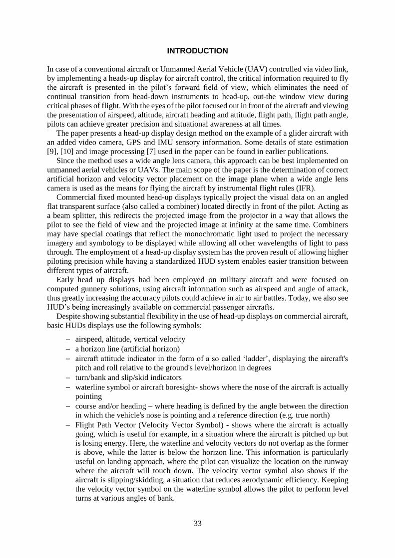
Regarding the terminology of the paper, the usual ECI, ECEF, NED and ABC (Aircraft Body
or shortly Body) coordinate systems (frames) used for aerial navigation are used, see Figure 1.
The frames are referred to by the indexes 𝑖, 𝑒, 𝑛, 𝑏.
Lacking an onboard navigation system, an external sensory system had been fitted on the
aircraft in the form of an accelerometer, angular velocity meter, magnetometer (IMU) and
differential GPS receivers. State estimation for the aircraft is based on a two level Extended
Kalman Filtering with an additional external correction loop. The state estimator also supplies
the data needed for displaying the Flight Path Vector in the form of flight path angle and drift
information in degrees.
The problems to be solved are:
accurately show the direction at which the nose of the aircraft is pointing
(Boresighting);
overlapping the vertical horizon line on the visible horizon line of the images supplied
by the wide angle lens camera;
displaying a set of compass values on the virtual horizon line so that the virtual cardinal
directions shown overlap the actual cardinal directions seen from the aircraft;
displaying the actual direction of flight by the means of a Flight Path Vector (FPV) by
taking into account the drift and actual angle of attack of the aircraft.
Figure 1. Coordinate systems used in navigation
35
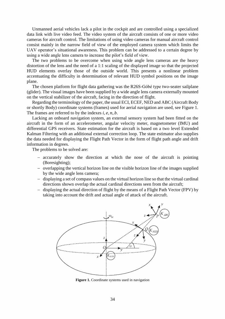
The signals belonging to the body frame are shown in Figure 2, where Φ,Θ,Ѱ denote the
Euler (roll, pitch, yaw) angles, 𝑈, 𝑉,𝑊 represent the velocity, 𝑃, 𝑄, 𝑅 the angular velocity,
𝑋, 𝑌, 𝑍 the force and 𝐿,𝑀,𝑁 the torque components, 𝑣𝑇 is the magnitude of the velocity, 𝛼 is
the angle of attack and 𝛽 is the sideslip angle.
Figure 2. Aircraft frame and kinematic force/torque variables
DATA USED FOR DISPLAYING INFORMATION ON THE HEADS UP DISPLAY
For accurately displaying information needed to fly the airplane or unmanned aerial vehicle,
the variables on the HUD use the data supplied by the state estimator. The supplied data consists
of the following:
measured GPS position in the 𝐾𝑒 frame in [m]
estimated velocity in the aircraft’s 𝐾𝑏 frame of reference along its three axis in m/s
quaternion based orientation in 𝐾𝑏
The data supplied by the state estimator undergoes a transformation that allows it to be used
on the HUD. Firstly, the position of the aircraft measured in the 𝐾𝑒 frame has to be converted
to the 𝐾𝑛 frame used in aerial navigation. When displaying the height of the aircraft, the ‘Down’
axis position can be used. For using the QFE altimeter settings, the stationary position of the
aircraft has been used as a reference point to zero the altimeter.
The velocity of the aircraft is displayed according to its 𝑥𝑏values and converted from m/s to
km/h. Since the sensors available are not capable of measuring wind speed and direction, these
values are also estimated and taken into account when displaying the velocity of the aircraft.
Due to the fact the velocity of the aircraft is estimated in 𝐾𝑏 and the wind speed in 𝐾𝑛, the
following conversion needs to be implemented in order to get the correct data in 𝐾𝑏. By
knowing the direction and intensity of the wind, the projections of the wind effect on the 𝑥𝑛, 𝑦𝑛
axes are obtained:
𝑣𝑤𝑖𝑛𝑑_𝑛 = (𝑣𝑤𝑖𝑛𝑑 ⋅ 𝐶𝑤𝑖𝑛𝑑_𝑑𝑖𝑟𝑣𝑤𝑖𝑛𝑑 ⋅ 𝑆𝑤𝑖𝑛𝑑_𝑑𝑖𝑟
0
) (1)
Where the short forms 𝐶𝑤𝑖𝑛𝑑_𝑑𝑖𝑟 and 𝑆𝑤𝑖𝑛𝑑_𝑑𝑖𝑟 denote cos (𝑥) and sin (𝑥) respectively.
36
The aircraft velocity corrected for wind effects will be:
𝑣𝑎_𝑤_𝑛 = 𝑣𝑎_𝑛 + 𝑣𝑤𝑖𝑛𝑑_𝑛 (2)
Finally, the velocity of the aircraft corrected for wind effects in Kb will take the form of:
𝑣𝑎𝑖𝑟𝑐𝑟_𝑏 = 𝑅𝑏2𝑛
𝑇 ⋅ 𝑣𝑎_𝑤_𝑛 (3)
where:
𝑣𝑎𝑖𝑟𝑐𝑟_𝑏 = (
𝑈𝑏𝑉𝑏𝑊𝑏
) (4)
and:
𝑣𝑤𝑖𝑛𝑑 – wind direction and intensity in 𝐾𝑛
𝑣𝑎_𝑤_𝑛 – aircraft velocity corrected for wind effects
𝑣𝑎_𝑛 – estimated aircraft velocity
𝑣𝑤𝑖𝑛𝑑_𝑛 – estimated wind speed
𝑅𝑏2𝑛𝑇 – transpose of 𝐾𝑏 to 𝐾𝑛 transformation matrix
The vertical velocity indicator of the HUD uses the aircrafts velocity along its ‘Down’ axis in
m/s after a conversion to the 𝐾𝑛 frame.
The quaternion based orientation of the aircraft is firstly converted to Euler’s RPY angles in
degrees and converted from 𝐾𝑏 to the 𝐾𝑛 frame using (5). This information is used to display
heading and the virtual horizon elements of the HUD. In this article the notation for the RPY
Euler angles will use Φ,Θ and Ѱ.
�̂�𝑏
𝑅𝐵2𝑁→ Φ𝑛 , Θ𝑛, Ѱ𝑛 (5)
The 𝛽 slip angle and 𝛼 angle of attack is calculated according to the following [3]:
𝛼 = 𝑎𝑡𝑎𝑛 (𝑊𝑏𝑈𝑏) (6)
𝛽 = 𝑎𝑠𝑖𝑛 (
𝑉𝑏𝑣𝑎𝑏𝑠
) (7)
where: 𝑣𝑎𝑏𝑠 = ‖𝑣𝑎𝑖𝑟𝑐𝑟_𝑏‖ (8)
VIDEO CAMERA CALIBRATION AND BORESIGHTING
To be able to display the required data accurately, the internal and external parameters of the
video camera have to be known. The internal parameters of the camera are: image size, focal
length, principal point, skew, radial and tangential distortion coefficients. The video camera’s
internal parameters are a priori identified using a chess board like picture rendition and the
camera’s K matrix is regarded as known [5]:
37
𝐾 = [𝑓𝑥 𝛼𝑐 ⋅ 𝑓𝑥 𝑐𝑥0 𝑓𝑦 𝑐𝑦0 0 1
] (9)
where:
𝑓𝑥 , 𝑓𝑦 - identified focal length in pixels
𝑐𝑥, 𝑐𝑦 - principal point of the camera
𝛼𝑐 - skew
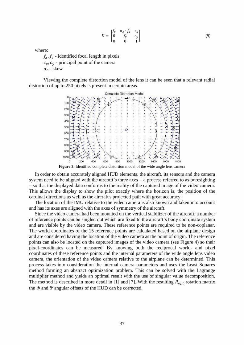
Viewing the complete distortion model of the lens it can be seen that a relevant radial
distortion of up to 250 pixels is present in certain areas.
Figure 3. Identified complete distortion model of the wide angle lens camera
In order to obtain accurately aligned HUD elements, the aircraft, its sensors and the camera
system need to be aligned with the aircraft’s three axes – a process referred to as boresighting
– so that the displayed data conforms to the reality of the captured image of the video camera.
This allows the display to show the pilot exactly where the horizon is, the position of the
cardinal directions as well as the aircraft's projected path with great accuracy.
The location of the IMU relative to the video camera is also known and taken into account
and has its axes are aligned with the axes of symmetry of the aircraft.
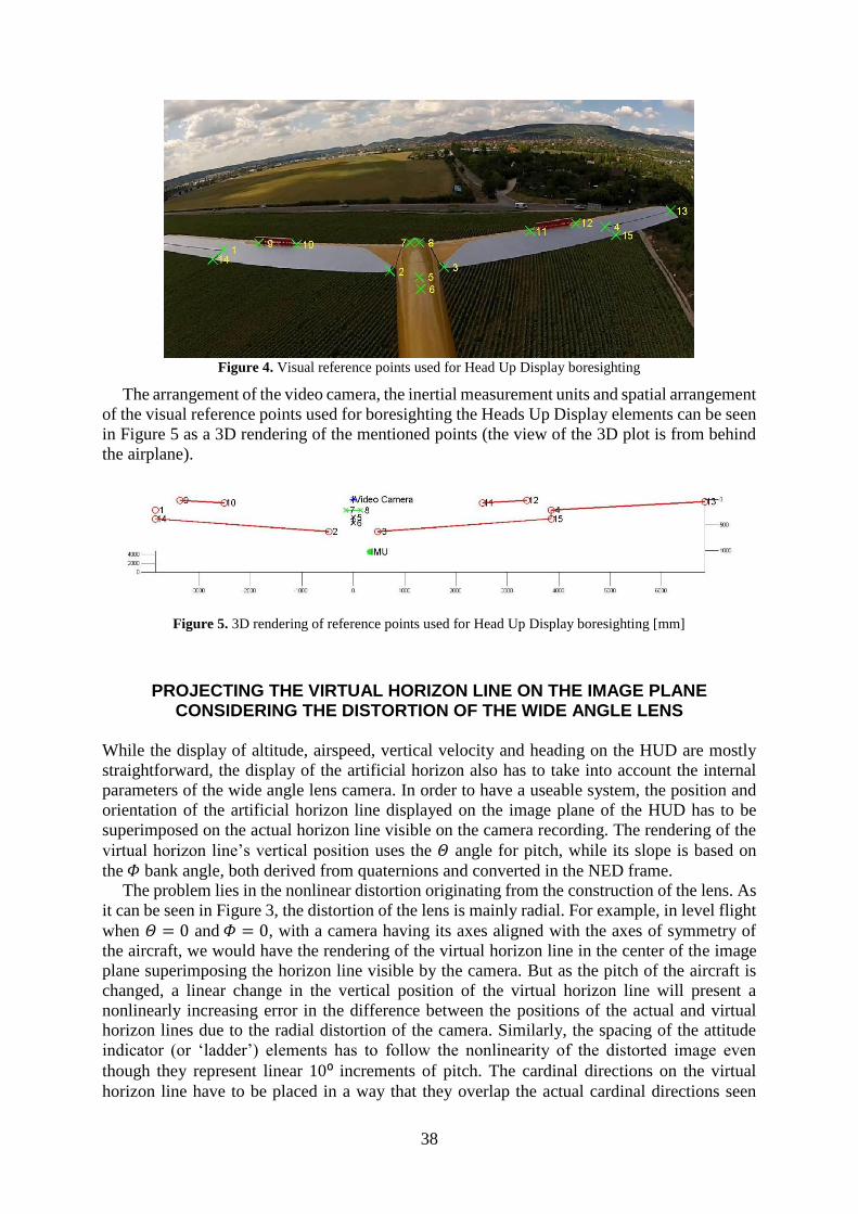
Since the video camera had been mounted on the vertical stabilizer of the aircraft, a number
of reference points can be singled out which are fixed to the aircraft’s body coordinate system
and are visible by the video camera. These reference points are required to be non-coplanar.
The world coordinates of the 15 reference points are calculated based on the airplane design
and are considered having the location of the video camera as the point of origin. The reference
points can also be located on the captured images of the video camera (see Figure 4) so their
pixel-coordinates can be measured. By knowing both the reciprocal world- and pixel
coordinates of these reference points and the internal parameters of the wide angle lens video
camera, the orientation of the video camera relative to the airplane can be determined. This
process takes into consideration the internal camera parameters and uses the Least Squares
method forming an abstract optimization problem. This can be solved with the Lagrange
multiplier method and yields an optimal result with the use of singular value decomposition.
The method is described in more detail in [1] and [7]. With the resulting 𝑅𝑜𝑝𝑡 rotation matrix
the Φ and Ѱ angular offsets of the HUD can be corrected.
38
Figure 4. Visual reference points used for Head Up Display boresighting
The arrangement of the video camera, the inertial measurement units and spatial arrangement
of the visual reference points used for boresighting the Heads Up Display elements can be seen
in Figure 5 as a 3D rendering of the mentioned points (the view of the 3D plot is from behind
the airplane).
Figure 5. 3D rendering of reference points used for Head Up Display boresighting [mm]
PROJECTING THE VIRTUAL HORIZON LINE ON THE IMAGE PLANE CONSIDERING THE DISTORTION OF THE WIDE ANGLE LENS
While the display of altitude, airspeed, vertical velocity and heading on the HUD are mostly
straightforward, the display of the artificial horizon also has to take into account the internal
parameters of the wide angle lens camera. In order to have a useable system, the position and
orientation of the artificial horizon line displayed on the image plane of the HUD has to be
superimposed on the actual horizon line visible on the camera recording. The rendering of the
virtual horizon line’s vertical position uses the 𝛩 angle for pitch, while its slope is based on
the 𝛷 bank angle, both derived from quaternions and converted in the NED frame.
The problem lies in the nonlinear distortion originating from the construction of the lens. As
it can be seen in Figure 3, the distortion of the lens is mainly radial. For example, in level flight
when 𝛩 = 0 and 𝛷 = 0, with a camera having its axes aligned with the axes of symmetry of
the aircraft, we would have the rendering of the virtual horizon line in the center of the image
plane superimposing the horizon line visible by the camera. But as the pitch of the aircraft is
changed, a linear change in the vertical position of the virtual horizon line will present a
nonlinearly increasing error in the difference between the positions of the actual and virtual
horizon lines due to the radial distortion of the camera. Similarly, the spacing of the attitude
indicator (or ‘ladder’) elements has to follow the nonlinearity of the distorted image even
though they represent linear 10⁰ increments of pitch. The cardinal directions on the virtual
horizon line have to be placed in a way that they overlap the actual cardinal directions seen
39
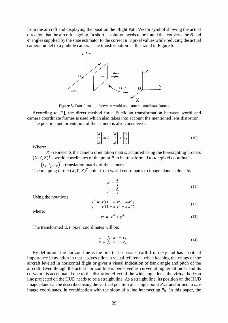
from the aircraft and displaying the position the Flight Path Vector symbol showing the actual
direction that the aircraft is going. In short, a solution needs to be found that converts the 𝛩 and
𝛷 angles supplied by the state estimator to the correct 𝑢, 𝑣 pixel values while reducing the actual
camera model to a pinhole camera. The transformation is illustrated in Figure 5.
Figure 5. Transformation between world and camera coordinate frames
According to [2], the direct method for a Euclidian transformation between world and
camera coordinate frames is used which also takes into account the mentioned lens distortion.
The position and orientation of the camera is also considered:
[𝑋𝑌𝑍] = 𝑅 ⋅ [
𝑋𝑌𝑍] + [
𝑡𝑥𝑡𝑦𝑡𝑧
] (10)
Where:
𝑅 - represents the camera orientation matrix acquired using the boresighting process
(𝑋, 𝑌, 𝑍)𝑇 - world coordinates of the point 𝑃 to be transformed to 𝑢, 𝑣pixel coordinates
(𝑡𝑥, 𝑡𝑦, 𝑡𝑧)𝑇- translation matrix of the camera
The mapping of the (𝑋, 𝑌, 𝑍)𝑇 point from world coordinates to image plane is done by:
𝑥′ =
𝑥
𝑧
𝑦′ = 𝑦
𝑧
(11)
Using the notations: 𝑥′′ = 𝑥′(1 + 𝑘1𝑟
2 + 𝑘2𝑟4)
𝑦′′ = 𝑦′(1 + 𝑘1𝑟2 + 𝑘2𝑟
4) (12)
where: 𝑟2 = 𝑥′
2+ 𝑦′
2 (13)
The transformed 𝑢, 𝑣 pixel coordinates will be:
𝑢 = 𝑓𝑥 ⋅ 𝑥
′′ + 𝑐𝑥
𝑣 = 𝑓𝑦 ⋅ 𝑦′′ + 𝑐𝑦
(14)
By definition, the horizon line is the line that separates earth from sky and has a critical
importance in aviation in that it gives pilots a visual reference when keeping the wings of the
aircraft leveled in horizontal flight or gives a visual indication of bank angle and pitch of the
aircraft. Even though the actual horizon line is perceived as curved at higher altitudes and its
curvature is accentuated due to the distortion effect of the wide angle lens, the virtual horizon
line projected on the HUD needs to be a straight line. As a straight line, its position on the HUD
image plane can be described using the vertical position of a single point 𝑃𝐻 transformed to 𝑢, 𝑣
image coordinates, in combination with the slope of a line intersecting 𝑃𝐻. In this paper, the
40
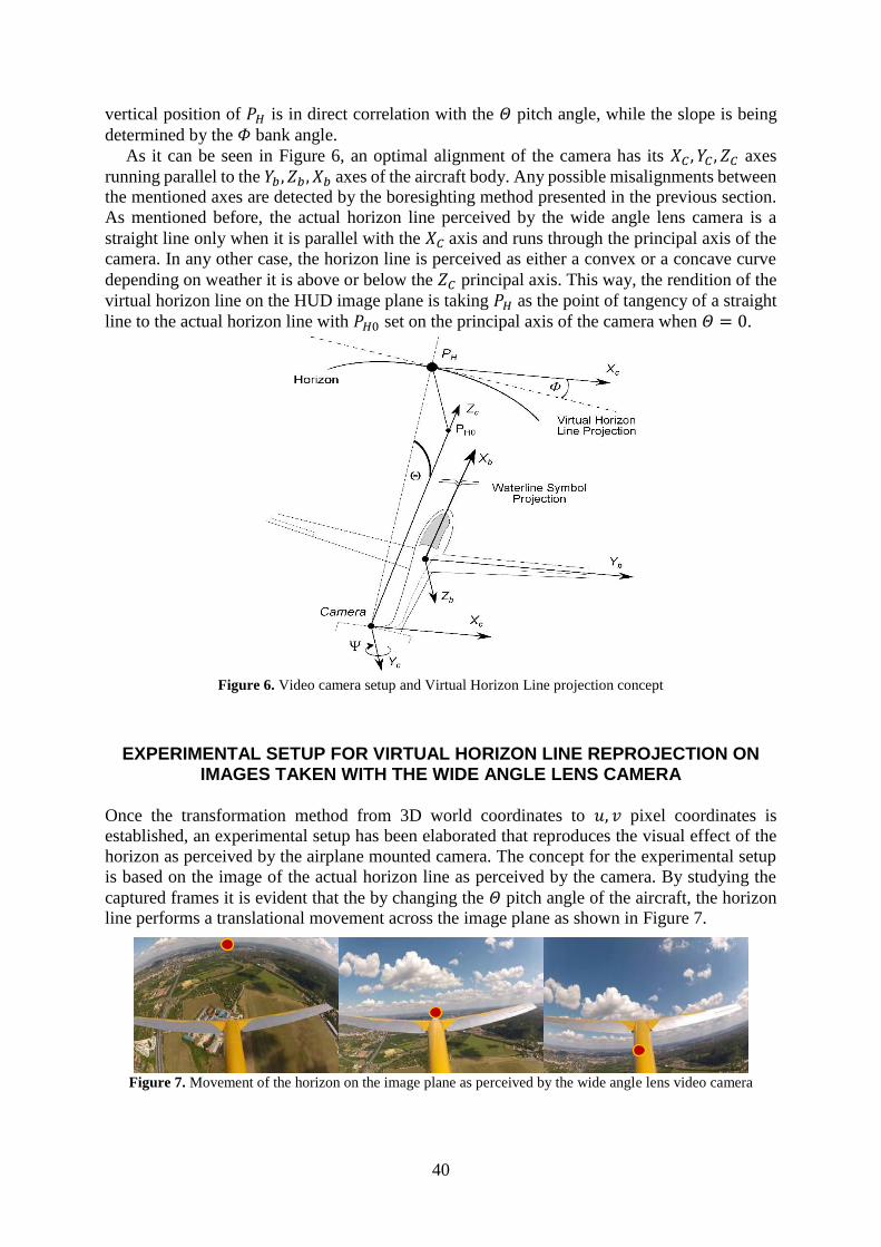
vertical position of 𝑃𝐻 is in direct correlation with the 𝛩 pitch angle, while the slope is being
determined by the 𝛷 bank angle.
As it can be seen in Figure 6, an optimal alignment of the camera has its 𝑋𝐶 , 𝑌𝐶 , 𝑍𝐶 axes
running parallel to the 𝑌𝑏 , 𝑍𝑏 , 𝑋𝑏 axes of the aircraft body. Any possible misalignments between
the mentioned axes are detected by the boresighting method presented in the previous section.
As mentioned before, the actual horizon line perceived by the wide angle lens camera is a
straight line only when it is parallel with the 𝑋𝐶 axis and runs through the principal axis of the
camera. In any other case, the horizon line is perceived as either a convex or a concave curve
depending on weather it is above or below the 𝑍𝐶 principal axis. This way, the rendition of the
virtual horizon line on the HUD image plane is taking 𝑃𝐻 as the point of tangency of a straight
line to the actual horizon line with 𝑃𝐻0 set on the principal axis of the camera when 𝛩 = 0.
Figure 6. Video camera setup and Virtual Horizon Line projection concept
EXPERIMENTAL SETUP FOR VIRTUAL HORIZON LINE REPROJECTION ON IMAGES TAKEN WITH THE WIDE ANGLE LENS CAMERA
Once the transformation method from 3D world coordinates to 𝑢, 𝑣 pixel coordinates is
established, an experimental setup has been elaborated that reproduces the visual effect of the
horizon as perceived by the airplane mounted camera. The concept for the experimental setup
is based on the image of the actual horizon line as perceived by the camera. By studying the
captured frames it is evident that the by changing the 𝛩 pitch angle of the aircraft, the horizon
line performs a translational movement across the image plane as shown in Figure 7.
Figure 7. Movement of the horizon on the image plane as perceived by the wide angle lens video camera
41
This simplification is performed with regards to the fact that for pitch control the position of a
single point 𝑃𝐻 relative to the 𝑋𝐶 axis of the camera is sufficient, noting that 𝑃𝐻 is formed by
the intersection between the visible horizon line and the 𝑌𝐶 , 𝑍𝐶 plane (see Figure 6). Due to the
fact that 𝑃𝐻 is a point, no perspective issues arise.
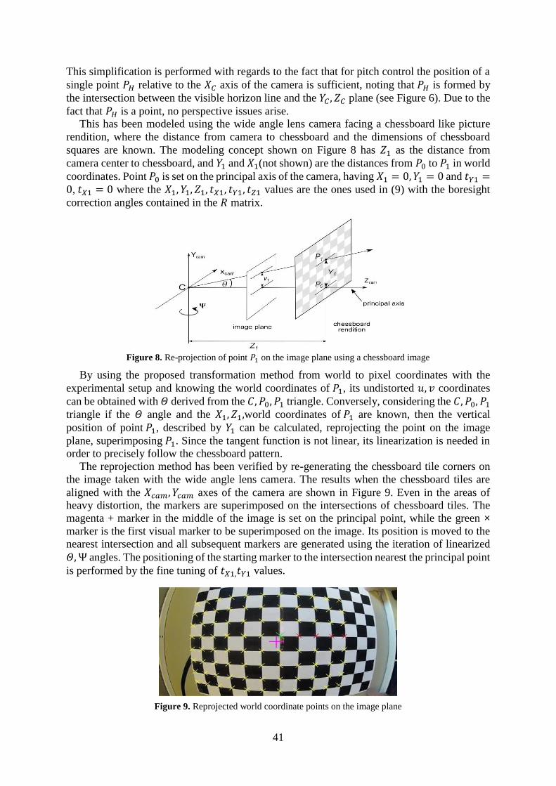
This has been modeled using the wide angle lens camera facing a chessboard like picture
rendition, where the distance from camera to chessboard and the dimensions of chessboard
squares are known. The modeling concept shown on Figure 8 has 𝑍1 as the distance from
camera center to chessboard, and 𝑌1 and 𝑋1(not shown) are the distances from 𝑃0 to 𝑃1 in world
coordinates. Point 𝑃0 is set on the principal axis of the camera, having 𝑋1 = 0, 𝑌1 = 0 and 𝑡𝑌1 =0, 𝑡𝑋1 = 0 where the 𝑋1, 𝑌1, 𝑍1, 𝑡𝑋1, 𝑡𝑌1, 𝑡𝑍1 values are the ones used in (9) with the boresight
correction angles contained in the 𝑅 matrix.
Figure 8. Re-projection of point 𝑃1 on the image plane using a chessboard image
By using the proposed transformation method from world to pixel coordinates with the
experimental setup and knowing the world coordinates of 𝑃1, its undistorted 𝑢, 𝑣 coordinates
can be obtained with 𝛩 derived from the 𝐶, 𝑃0, 𝑃1 triangle. Conversely, considering the 𝐶, 𝑃0, 𝑃1 triangle if the 𝛩 angle and the 𝑋1, 𝑍1,world coordinates of 𝑃1 are known, then the vertical
position of point 𝑃1, described by 𝑌1 can be calculated, reprojecting the point on the image
plane, superimposing 𝑃1. Since the tangent function is not linear, its linearization is needed in
order to precisely follow the chessboard pattern.
The reprojection method has been verified by re-generating the chessboard tile corners on
the image taken with the wide angle lens camera. The results when the chessboard tiles are
aligned with the 𝑋𝑐𝑎𝑚, 𝑌𝑐𝑎𝑚 axes of the camera are shown in Figure 9. Even in the areas of
heavy distortion, the markers are superimposed on the intersections of chessboard tiles. The
magenta + marker in the middle of the image is set on the principal point, while the green ×
marker is the first visual marker to be superimposed on the image. Its position is moved to the
nearest intersection and all subsequent markers are generated using the iteration of linearized
𝛩,Ѱ angles. The positioning of the starting marker to the intersection nearest the principal point
is performed by the fine tuning of 𝑡𝑋1,𝑡𝑌1 values.
Figure 9. Reprojected world coordinate points on the image plane
42
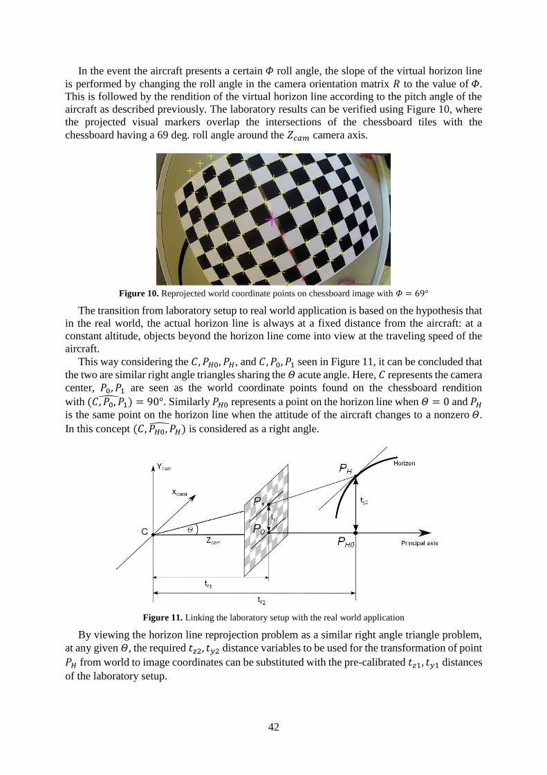
In the event the aircraft presents a certain 𝛷 roll angle, the slope of the virtual horizon line
is performed by changing the roll angle in the camera orientation matrix 𝑅 to the value of 𝛷.
This is followed by the rendition of the virtual horizon line according to the pitch angle of the
aircraft as described previously. The laboratory results can be verified using Figure 10, where
the projected visual markers overlap the intersections of the chessboard tiles with the
chessboard having a 69 deg. roll angle around the 𝑍𝑐𝑎𝑚 camera axis.
Figure 10. Reprojected world coordinate points on chessboard image with 𝛷 = 69°
The transition from laboratory setup to real world application is based on the hypothesis that
in the real world, the actual horizon line is always at a fixed distance from the aircraft: at a
constant altitude, objects beyond the horizon line come into view at the traveling speed of the
aircraft.
This way considering the 𝐶, 𝑃𝐻0, 𝑃𝐻, and 𝐶, 𝑃0, 𝑃1 seen in Figure 11, it can be concluded that
the two are similar right angle triangles sharing the 𝛩 acute angle. Here, 𝐶 represents the camera
center, 𝑃0, 𝑃1 are seen as the world coordinate points found on the chessboard rendition
with (𝐶, 𝑃0, 𝑃1)̂ = 90°. Similarly 𝑃𝐻0 represents a point on the horizon line when 𝛩 = 0 and 𝑃𝐻
is the same point on the horizon line when the attitude of the aircraft changes to a nonzero 𝛩.
In this concept (𝐶, 𝑃𝐻0, 𝑃𝐻)̂ is considered as a right angle.
Figure 11. Linking the laboratory setup with the real world application
By viewing the horizon line reprojection problem as a similar right angle triangle problem,
at any given 𝛩, the required 𝑡𝑧2, 𝑡𝑦2 distance variables to be used for the transformation of point
𝑃𝐻 from world to image coordinates can be substituted with the pre-calibrated 𝑡𝑧1, 𝑡𝑦1 distances
of the laboratory setup.
43
HEADS UP DISPLAY APPLICATION USING ACTUAL FLIGHT DATA
Besides laboratory testing, the presented method has been verified by constructing a working
Heads Up Display using the aircraft mounted wide angle lens video camera during flight and
actual flight data.
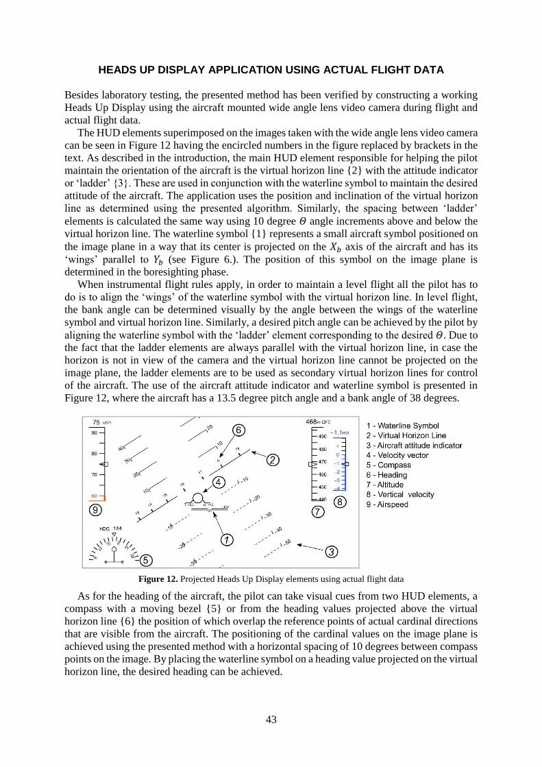
The HUD elements superimposed on the images taken with the wide angle lens video camera
can be seen in Figure 12 having the encircled numbers in the figure replaced by brackets in the
text. As described in the introduction, the main HUD element responsible for helping the pilot
maintain the orientation of the aircraft is the virtual horizon line {2} with the attitude indicator
or ‘ladder’ {3}. These are used in conjunction with the waterline symbol to maintain the desired
attitude of the aircraft. The application uses the position and inclination of the virtual horizon
line as determined using the presented algorithm. Similarly, the spacing between ‘ladder’
elements is calculated the same way using 10 degree 𝛩 angle increments above and below the
virtual horizon line. The waterline symbol {1} represents a small aircraft symbol positioned on
the image plane in a way that its center is projected on the 𝑋𝑏 axis of the aircraft and has its
‘wings’ parallel to 𝑌𝑏 (see Figure 6.). The position of this symbol on the image plane is
determined in the boresighting phase.
When instrumental flight rules apply, in order to maintain a level flight all the pilot has to
do is to align the ‘wings’ of the waterline symbol with the virtual horizon line. In level flight,
the bank angle can be determined visually by the angle between the wings of the waterline
symbol and virtual horizon line. Similarly, a desired pitch angle can be achieved by the pilot by
aligning the waterline symbol with the ‘ladder’ element corresponding to the desired 𝛩. Due to
the fact that the ladder elements are always parallel with the virtual horizon line, in case the
horizon is not in view of the camera and the virtual horizon line cannot be projected on the
image plane, the ladder elements are to be used as secondary virtual horizon lines for control
of the aircraft. The use of the aircraft attitude indicator and waterline symbol is presented in
Figure 12, where the aircraft has a 13.5 degree pitch angle and a bank angle of 38 degrees.
Figure 12. Projected Heads Up Display elements using actual flight data
As for the heading of the aircraft, the pilot can take visual cues from two HUD elements, a
compass with a moving bezel {5} or from the heading values projected above the virtual
horizon line {6} the position of which overlap the reference points of actual cardinal directions
that are visible from the aircraft. The positioning of the cardinal values on the image plane is
achieved using the presented method with a horizontal spacing of 10 degrees between compass
points on the image. By placing the waterline symbol on a heading value projected on the virtual
horizon line, the desired heading can be achieved.
44
The airspeed {9}, altitude {7} and vertical velocity {8} indicators have moving bezels with
the actual values displayed numerically above the indicator boxes. All three indicators have
scales moving behind a fixed arrow found in the middle of the indicator boxes. Moving scales
have an advantage over numerical displays in being able to conveniently display the operating
ranges of the aircraft, for example, by using a color coding on the airspeed indicator.
In this case, the 60 km/h stall speed of the aircraft is visible in orange and helps the pilot to
intuitively determine how close the aircraft is to a stall. Minimum and maximum flaps and
landing gear retraction and extension speeds can also be displayed using this method.
The Flight Path Vector or FPV {4} shows the aircraft as seen from behind and represents
the direction the aircraft is actually moving as this does not always coincide with the direction
the nose of the aircraft is pointing (Waterline symbol). Its use significantly reduces pilot
workload on landing approaches and when flying in crosswinds. The position of the FPV
coincides with that of the waterline symbol in cases when the angle of attack 𝛼 = 0 and the slip
angle β = 0. The position of the FPV on the image plane and its deviation from its neutral
position is also determined with the presented method according to the angular values of 𝛼
and β.
Placement of the FPV along the pitch axis indicates the Flight path angle (FPA). When the
FPV is on the horizon line, the FPA is zero (level flight). If the FPV is above the horizon line,
the airplane is climbing; below the line, the airplane is descending regardless where the nose of
the aircraft is pointing. The angle of climb or descent corresponds to where the center of the
FPV intersects the pitch scale so flying the FPV to 3° below the horizon always produces a 3°
glidepath. In the case presented in Figure 12, as a left hand turn is performed, even though its
nose is pointing to -13.5 degrees, the flight path angle of the aircraft is only -4.5 degrees.
In the case presented in Figure 12, the FPV also shows that the aircraft is slipping, meaning
that it is sideways to the relative airflow. This undesirable state can thus be visualized and
corrected using the FPV.
RESULTS
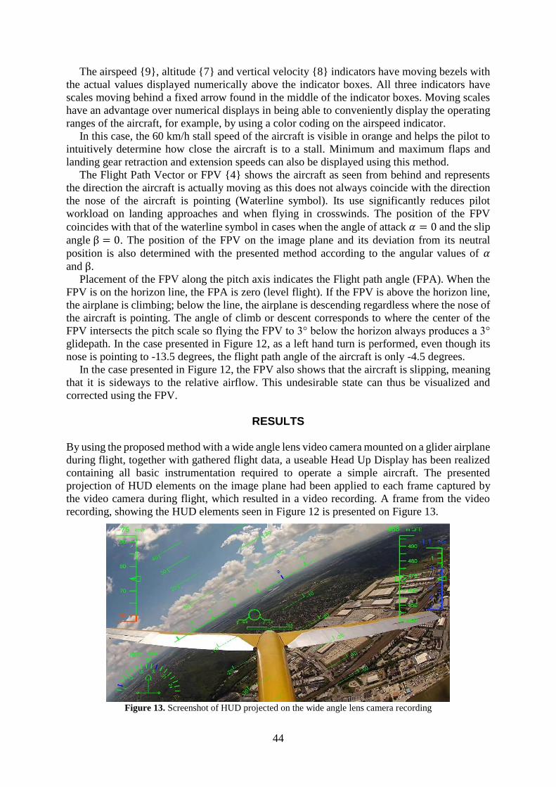
By using the proposed method with a wide angle lens video camera mounted on a glider airplane
during flight, together with gathered flight data, a useable Head Up Display has been realized
containing all basic instrumentation required to operate a simple aircraft. The presented
projection of HUD elements on the image plane had been applied to each frame captured by
the video camera during flight, which resulted in a video recording. A frame from the video
recording, showing the HUD elements seen in Figure 12 is presented on Figure 13.
Figure 13. Screenshot of HUD projected on the wide angle lens camera recording
45
The validation of the proposed method had been performed in two ways. Firstly, by visual
verification of the alignment of the actual horizon with the position of the virtual horizon line,
and secondly, by means of image processing.
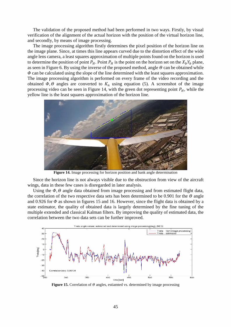
The image processing algorithm firstly determines the pixel position of the horizon line on
the image plane. Since, at times this line appears curved due to the distortion effect of the wide
angle lens camera, a least squares approximation of multiple points found on the horizon is used
to determine the position of point 𝑃𝐻. Point 𝑃𝐻 is the point on the horizon set on the 𝑋𝑏𝑌𝑏 plane,
as seen in Figure 6. By using the inverse of the proposed method, angle 𝛩 can be obtained while
𝛷 can be calculated using the slope of the line determined with the least squares approximation.
The image processing algorithm is performed on every frame of the video recording and the
obtained 𝛷, 𝛩 angles are converted to 𝐾𝑛 using equation (5). A screenshot of the image
processing video can be seen in Figure 14, with the green dot representing point 𝑃𝐻, while the
yellow line is the least squares approximation of the horizon line.
Figure 14. Image processing for horizon position and bank angle determination
Since the horizon line is not always visible due to the obstruction from view of the aircraft
wings, data in these few cases is disregarded in later analysis.
Using the 𝛷,𝛩 angle data obtained from image processing and from estimated flight data,
the correlation of the two respective data sets has been determined to be 0.901 for the 𝛩 angle
and 0.926 for 𝛷 as shown in figures 15 and 16. However, since the flight data is obtained by a
state estimator, the quality of obtained data is largely determined by the fine tuning of the
multiple extended and classical Kalman filters. By improving the quality of estimated data, the
correlation between the two data sets can be further improved.
Figure 15. Correlation of 𝛩 angles, estiamted vs. determined by image processing

46
Figure 16. Correlation of 𝛷 angles, estiamted vs. determined by image processing
CONCLUSION
The paper presented methods and algorithms to solve the problem of a Heads Up Display
projection on images taken with a wide angle lens camera. The method can prove especially
useful in unmanned aerial vehicle control, where the use of a wide angle lens increases the field
of view of the pilot thus increasing situational awareness. However, the use of a wide angle lens
camera introduces severe distortion effects, a nonlinear problem that needs to be solved when
placing the HUD elements responsible for attitude control on the image plane.
The paper gives a viable method for overcoming this problem, while realizing the 1:1 scaling
of the displayed images so that the projected HUD elements overlay those of the outside world.
This is achieved at a low computational cost implementable on portable systems.
References
[1] Tél F, Stereo Image Processing System for Robotic Applications, PhD Thesis. Budapest
University of Technology and Economics, Department of Control Engineering and
Information Technology, Budapest, 2009
[2] R. Hartley and A. Zissermann, Multiple View Geometry in Computer Vision. Cambridge
University Press, 2003
[3] B. Lantos and L. Márton, Nonlinear Control Of Vehicles and Robots. London: Springer,
2011
[4] Zhengyou Zhang, On the Epipolar Geometry Between Two Images With Lens
distortion, Proc. Int’l Conf. Pattern Recognition (ICPR), Vol. I, pages 407-411, Aug.
1996, Vienna
[5] Zhengyou Zhang, A Flexible New Technique for Camera Calibration, IEEE
Transactions on Pattern Analysis and Machine Intelligence, Vol. 22, No. 11, November
2000
[6] Heikkila, J. and Silven, O, A four-step camera calibration procedure with implicit
image correction. CVPR97, 1997
[7] L. Lukács and B. Lantos, Data Fusion and Primary Image Processing for Aircraft
Identification. Periodica Polytechnica, electrical Engineering and Computer Science,
56/3, pages 83-94, Budapest 2012
[8] Ed. Cary R. Spitzer, The Avionics Handbook. Boca Raton, CRC Press LLC. 2001
47
[9] L. Lukács, State Estimation Method For Aircraft Identification Purposes. 9-th IEEE
Symposium on Applied Computational Intelligence and Informatics, pages 31-35, May
15-17, Timisoara 2014
[10] L. Lukács and B. Lantos, Identification of the nonlinear dynamic model of sailplanes
involving state estimation and image processing for actuator signal computation. 12-th
IEEE International Symposium on Intelligent Systems and Informatics, accepted for
publication, September 11-13, Subotica 2014


![State of Augmented Reality, Virtual Reality and Mixed Reality · State of Augmented Reality, Virtual Reality and Mixed Reality [Microsoft Hololen] [Ready Player One] Augmented Reality](https://img.pdfslide.us/doc/110x75/5f82ab6da2d89130b90d78c7/state-of-augmented-reality-virtual-reality-and-mixed-reality-state-of-augmented.jpg)