Embed Size (px)
Citation preview
8122019 augi world 2013 10
httpslidepdfcomreaderfullaugi-world-2013-10 152
Personalized
ProductsCustomizingAutodesk Software
wwwaugiworldcom
Also in this issue
bull Transition Roadmap for Revit MEP
bull 10 Inventor App Exchange Reviews
bull The AutoCAD Rainbow
US $800
October 2013AUGIWorldT h e O f f i c i a l P u b l i c a t i o n o f A u t o d e s k U s e r G r o u p I n t e r n a t i o n a l
Diamond Sponsor
8122019 augi world 2013 10
httpslidepdfcomreaderfullaugi-world-2013-10 252
8122019 augi world 2013 10
httpslidepdfcomreaderfullaugi-world-2013-10 352
contents
columns
15 28
4836
4 Editorrsquos Note
22 AUGI Forums String Theory
51 Inside Track
Cover mage
Project West Valley-Mission CollegeCCD Mission College Main BuildingReplacement Phase II
Software used Revit (BIM) 3ds MaxDesign (rendering) Photoshop (post-
production)Lionakis 2012
AUGIWorld
6 AutoCAD The AutoCAD Rainbow
10 AutoCAD Architecture Efficiency with
Renovation Mode
15 Inventor 10 App Exchange Reviews
24 Revit Architecture Myth Buster Revit amp IFC
Part 3
28 3ds Max Customizing the UI
36 AutoCAD MEP BIM Is Whatrsquos Driving the
Industry
40 Revit Structure Streamlining Sheet Lists with
a Custom Application
44 AutoCAD Civil 3D Customize Correctly
48 Revit MEP Transition Roadmap
8122019 augi world 2013 10
httpslidepdfcomreaderfullaugi-world-2013-10 452
wwwaugiworld com
EditorsEditor-in-Chief David Harrington - davidharringtonaugicom
Copy EditorMarilyn Law - marilynlawaugicom
Layout EditorTim Varnau - timvarnauaugicom
Content Managers3ds Max - Brian ChapmanAutoCAD - Curt MorenoAutoCAD Architecture - Melinda HeavrinAutoCAD Civil 3D - Christopher FugittAutoCAD MEP - William CampbellColumn Inside Track - Lee AmbrosiusInventor - John EvansNavisworks - Michael SmithProduct Review - Lonnie CumptonRevit Architecture - Jay ZallanRevit MEP - Todd ShackelfordRevit Structure - Phil Russo
Advertising Reprint SalesDavid Harrington - salesdirectoraugicom
AUGI Management
President
David Harrington
Vice-President
R Robert Bell
Treasurer
Desireacutee Mackey
Secretary
Melanie Perry
Community Director
Kevin Merritt
AUGI Board of DirectorsShaun Bryant
Tommy HolderKate Morrical
Michael Smith
Matt Worland
Scott Wilcox
Publication InformationAUGIWorld magazine is a benefit of specificAUGI membership plans Direct magazinesubscriptions are not available Please visithttpwwwaugicomaccountregister to join or up-grade your membership to receiveAUGIWorld magazine in print To manage your AUGI membership andaddress please visit httpwwwaugicomaccount For all other magazine inquires please contactaugiworldaugicom
Published by
AUGIWorld is published by Autodesk User GroupInternational Inc AUGI makes no warranty for theuse of its products and assumes no responsibility forany errors which may appear in this publication nordoes it make a commitment to update the informatiocontained herein
AUGIWorld is Copyright copy2013 AUGI No informa-tion in this magazine may be reproduced withoutexpressed written permission from AUGI
All registered trademarks and trademarks included this magazine are held by their respective companieEvery attempt was made to include all trademarksand registered trademarks where indicated by theircompanies
AUGIWorld (San Francisco Calif)ISSN 2163-7547
Hello AUGIWorld Reader
Welcome to the October 2013 issue which isgenerally focused on customization of Autodesksoftware Tis is a nebulous subject as one personrsquossimple customization is anotherrsquos advanced highly
enhanced software add-on
But before we run down who and what is in this awesome issue a quick mention ofour wonderful cover graphic Tis was created by the team at Lionakis and is the 2nd
place winner for Best Presentation at the recent 2013 Revit echnology ConferenceNorth America It is always very interesting how people use Autodesk softwarealong with other products to create some really wonderful work
We begin this month with an article by Curt Moreno who is discussing the rainbowof AutoCAD flavors available in todayrsquos workplace We follow this with a pieceby Michael Beall sharing how to find settings for variables And then we have thevenerable Melinda Heavrin covering AutoCAD Architecture and Renovation mode
Next up is a review by Mark Flayler of 10 Exchange Apps for Inventor You simplydonrsquot know what you donrsquot knowmdashyou really need to check this out Melanie Perry
returns this month with her new column String Teory which highlights some ofthe most interesting AUGI Forum threads of the month And then Martijn de Rietbrings us part 3 of Revit and IFC busting myths for the final time
We then have Chris Murray who brings us customizing essentials for the userinterface in 3ds Max He shows us how to create a custom UI scheme for Max 2014Next we have Vladimir riantafillidis discussing AutoCAD MEP and helping toexplain what is driving the MEP industry And then Jonathan Albert shows how tostreamline using AutoCAD sheet sets with Revit Structure
Switching to the AutoCAD Civil 3D world ench ilghman explains how to
customize correctly (always a great goal to have) Ten odd Shackelford breaksdown the transitional roadmap when using Revit MEP It is much more than justsoftware guys Lastly Lee Ambrosius brings us the monthly Inside rack columnwith new releases from CSC SofiSiK and Autodesk
And with that this issue is a wrap urn the page and get to customizing Autodesksoftware
ake care
David Harrington
Editorrsquos Note
OCTOBER2013
AUGIWorld
8122019 augi world 2013 10
httpslidepdfcomreaderfullaugi-world-2013-10 552
BIM LibraryARCAT has the most comprehensive collecon of BIM objectsyou will find available free of charge and without registraon
The ARCAT BIM Library is also accessible in the ARCAT app
with eding capabilies in the AutoCAD 360 app
arcatcom facebook
8122019 augi world 2013 10
httpslidepdfcomreaderfullaugi-world-2013-10 652wwwaugicom October 20
AutoCAD 2014
PRO
DUCT
FOCUS
by Curt Moren
When you are a long-time CADprofessional and AutoCADreg user ina position where you provide supportto others every phone call can bring
something new to you Maybe the phone will ringand someone will need help using AutoCAD to create a designfor a life-saving medical device Or maybe the phone will ring and
someone will need help with the next great design for front-endsuspension on a luxury car Or maybe it is a first-time user callingwith a question that yoursquove never even heard before Unfortunatelyit is most likely going to be someone asking you the same questionthat you have been asked 10000 times before
Tat call is the one that came today Ringhellip ringhellip ldquoHi Irsquove beenusing AutoCAD for a few years and now I have to do this joband I want to customize my AutoCAD What would you dordquoTatrsquos right it was the dreaded ldquohow do I customize AutoCADrdquocall Over the years I have gotten this call more times than Icare to count
Tere was a time when I would have taken more time to discuworkflows and industry specifics with the caller I would hagotten my little yellow sticky notes and made scribbles about othscribbles Inevitably I would have had to do some research ancheck some prices and then report back to this caller
In 1991 the world was very different If you worked in a certa
industry and wanted your AutoCAD installation to have librariand scripts specific to your industry things were not easy Yohad to delve deep into the dark arts of variables and plug-ins Yohad to purchase libraries and install side applications Maybe yoeven wrote your own LISP routines and made your own customenus imes are different now and like the Monkees said ldquoTwas then this is nowrdquo In 2013 I sort of wonder why people whwant industry specific customizations even want to go through tprocess of customization
oday Autodesk offers so many flavors of AutoCAD that choosia certain version is more akin to choosing a new flavor of ice creaat Baskin Robbins than buying software If you are working in t
TheAutoCAD
Rainbow
8122019 augi world 2013 10
httpslidepdfcomreaderfullaugi-world-2013-10 752October 2013 wwwaugiworldcom
AutoCAD 2014
civil engineering field then AutoCADreg Civil 3Dreg is the AutoCADfor you For those in the utility market AutoCADreg Utility Designis your choice Te list goes on but more on that later rulytodayrsquos modern AutoCAD has fulfilled the promise of a ldquoplatformrdquorather than a single product
Rather than spending this ldquoCustomizationrdquo issue of AUGIWorlddiscussing the endless ways in which you are able to outfit AutoCADwe are going to discuss the variety of AutoCAD packages on themarket All the software packages we will look at share not onlythe AutoCAD engine but also the interface Soon it will becomeobvious why I feel that patching plugging and twisting standardvanilla AutoCAD is not as necessary as it once was
AUTOCAD CIVIL 3DTe first AutoCAD variant we will look at is the one that I use
just about every single day AutoCAD Civil 3D Although Civil3D is a very close cousin to AutoCAD it is packed with tools androutines germane to civil engineering projects made for design anddocumentation Whether your infrastructure project is a retention
pond a neighborhood subdivision or a major highway Civil 3Dhas the tools for you
With features such as survey data collection and advanced gradingCivil 3D is stuffed full of just the types of tools civil designersneed Major features include advanced surface modeling functionscorridor design and modeling parcel design and advanced stylemanagement Tere are even newly enhanced tools for pipenetworks that include both pressure and gravity systems
As a long-time AutoCAD Civil 3D user I cannot imagine takingthe standard version of AutoCAD and customizing it to better
suit the needs of a civil engineering office
AUTOCAD ARCHITECTUREOne of Autodeskrsquos flagship products is the Autodeskreg Revitregcollection of programs Over the past few years Revit hasbecome the de facto standard in nearly every architecture officein the country With the increasing popularity of the BuildingInformation Modeling (BIM) concept Revit has spread evenfurther into adjacent disciplines As wonderful as Revit is inthe eyes of many CAD users it lacks one major feature theAutoCAD interface
Because Revit is a completely separate product from AutoCADit does not share the AutoCAD engine or interface Tat can be astumbling block and cause a steep learning curve for transitioningCAD professionals Never fear Autodesk has just the solution forthe CAD professional seeking to customize the tried-and-trueAutoCAD installation for a more architecturally oriented taskAutoCADreg Architecture
From the simplest sections and elevations to the most complexmaterials schedules and renovations AutoCAD Architecturebrings all the tools the AutoCAD professional needs to tackle theproject And all of it is powered by the familiar AutoCAD engineand features the familiar interface
Users moving from standard AutoCAD to AutoCAD Architecturewill begin making short work of just about any architecture taskWith enhanced tools for placing walls doors and windows layoutswill happen faster than ever Room documentation and advancedtagging and annotation features along with the industry-standardbuildingSMAR system Industry Foundation Class will makesharing work with others quick and easy
Going from AutoCAD to AutoCAD Architecture will helpexperienced users move from standard drafting to completearchitecture plan sets and rendering quickly and easily Check thisprogram out before digging around the Internet looking for a set
of pre-made door blocks to use
AUTOCAD MECHANICALAnother important product for Autodesk is Autodesk InventorregYou have no doubt heard of this powerful program but may havethought ldquoIrsquom too far into my career to move from AutoCAD tosomething newrdquo o that I would first say ldquoYoursquore never too oldrdquoSecondly I would take a moment to understand that feeling (wersquoveall been there) and tell you to check out AutoCADreg Mechanical
Designers working on a wide variety of mechanical projects willwelcome the features AutoCAD Mechanical has to offer Whetheryou are tired of drawing tension springs or you need some helpdetermining the perfect design for rotation pattern of your camyou are going to find a tool to help you here
Why would you take the time to find blocks even dynamicblocks or bolts or threads or any of that AutoCAD Mechanicalcomes with a multitude of tools that are perfectly suited for thissort of work Sporting a robust library of more than 700000discipline-specific parts and shapes support for multiplestandards and intelligent dynamic geometry this is a packageready to do some work Of course all of this sits atop the familiarAutoCAD interface
TODAY AUTODESK
OFFERS SO MANY
FLAVORS OF AUTOCAD
THAT CHOOSING A
CERTAIN VERSION ISMORE AKIN TO CHOOSING
A NEW FLAVOR OF
ICE CREAM AT BASKIN
ROBBINS THAN BUYING
SOFTWARE
8122019 augi world 2013 10
httpslidepdfcomreaderfullaugi-world-2013-10 852wwwaugicom October 20
AutoCAD 2014
PRO
DUCT
FOCUS
AUTOCAD ELECTRICALIt seems that one of the largest groups of users I meet looking tocustomize their AutoCAD installations work in the Electricalfields Whether it is a small contractor trying to find an economicalroute or a large outfit looking to retool I pose this question ldquoWhydonrsquot you check out AutoCADreg Electricalrdquo
Like all AutoCAD-based products AutoCAD Electrical is aproduct intended for both design and documentation Tat meanselectrical designers are going to find the tools they need all in onepackage that has the familiar AutoCAD interface and commandsin addition to many industry-specific functions Whether you arelaying out panels or bringing together your bill of materials thereis something here for you
One of the common (but unloved) tasks I hear electrical designersand CAD professionals discuss is creating Programmable LogicControls AutoCAD Electrical offers the automation and dynamiclogic that makes this sort of job much easier Not only willelectrical designers be able to choose from a prepared library of
more than 3000 PLC IO modules they can create their own PLCIO modules with the Module Builder tool Tat one feature aloneis enough to save any electrical designer or CAD professional froma head full of gray hair
Documentation tools are just as robust in AutoCAD Electrical asthe design tools Out of the box your designer or CAD professionalis going to be armed with automated report generation features tocreate bills of material terminal plans wire labels and much moreProbably just as fantastic is the fact that you can run reports on asheet a panel a section of design or just about any other selectionyou can need
Sure you could piece together all this sort of functionalityyourself You could go out and download modules and blocksfrom manufacturer sites or purchase plug-ins with similarroutines Ten you could do the installation and compatibilitydance but why AutoCAD Electrical is ready for the electricaldesigner or CAD professional now requiring no more effort thanto install it
THE REST OF THE RAINBOWWe have taken a look at three of the AutoCAD-based productsthat I point people to most often Te wonderful part is that thereis still a whole slew of products out there built on the AutoCAD
platform Users seeking to customize their AutoCAD installationwith model-based GIS tools PampID libraries or structuraldetailing documentation reports just need to check out the rest ofthe impressive collection of AutoCAD-based products
bull AutoCAD Architecture ndash for architectural layouts elevationsand other projects
bull AutoCAD Civil 3D ndash for all manner of civil engineeringprojects from roads to water systems
bull AutoCAD Electrical ndash for electrical distribution projectsbull AutoCAD Map 3D ndash for adding mapping and GIS data to
support planning projects
bull AutoCAD Mechanical ndash for a wide variety of mechanical amanufacturing projects
bull AutoCAD MEP ndash for adding mechanical electrical aplumbing documentation to building projects
bull AutoCAD PampID ndash for design and documentation in pipidesign projects
bull AutoCAD Plant 3D ndash for the 3D layout and design of proceand manufacturing facilities
bull AutoCAD Structural Detailing ndash for creating shop drawinfor steel and concrete structures
bull AutoCAD Utility Design ndash for the rules-based design anlayout of electrical distribution systems
THE END OF THE RAINBOWAs you can see there is wide variety of predesigned industrspecific flavors of AutoCAD From laying out processing facilitto bringing electrical water or sewer services to that facility therean AutoCAD out there for you If you are like me and many othCAD professionals I know you will probably find that selectione of these versions of AutoCAD is much quicker easier an
often cheaper than taking the time to search out purchase ainstall various plug-ins for a standard AutoCAD installation
While there are certainly other Autodesk products that performany of these functions they are not AutoCAD-based and whave different interfaces Tis change in user interface and produdesign can often bring a steep and unwanted learning curve tofirm or project By choosing an AutoCAD-based product you wnot only be adding specific functionality you will also be able benefit from the familiar AutoCAD design and user interface
So the next time you are considering taking the time to customiyour standard AutoCAD installation with various librariscripts or plug-ins think about the alternatives ake a mometo investigate the world of AutoCAD products that are readand available to serve your industry-specific needs You may surprised at how much benefit the rainbow of AutoCAD versiocan bring to your company
Based in Houston exas Curt is aCAD Coordinator for a civil engineer-ing firm and the owner and editor ofthe Kung Fu Drafter blog He beganusing AutoCAD with Release 10 and
has spent the past 20+ years workingwith various Autodesk products includ-ing AutoCAD Civil 3D Map 3Dand SketchBook Designer Curt is alsoa freelance content creator featuredAutodesk University speaker andtraining content developer In his sparetime Curt writes games and spendstime with his dog and horses
8122019 augi world 2013 10
httpslidepdfcomreaderfullaugi-world-2013-10 952October 2013 wwwaugiworldcom
AutoCAD 2014
And Herersquos theExpress Toolhellip
to Find the Settingsfor Variables
Variables come in two flavors (if you donrsquot count those thatare lsquoRead Onlyrsquo) Tose that are saved in the Drawing andthose that are saved in the Registry For example the variableCURSORSIZE is saved in the Registry Te variableEXSIZE is saved by Drawing
But what about the less obvious ones Did you know theOSMODE variablemdasha Registry settingmdashstores a bitcodethat represents the combination of Osnaps you have set Wersquollactually be covering that tidbit in my 90-minute Lab at Autodesk University this year ldquoClick My Ride Customizing AutodeskregAutoCADreg for How You Workrdquo
SYSTEM VARIABLES EDITOROn the Express ools tab gtools panel click System Variables
Terersquos a field at the top that acts as a search feature and thataccepts wildcard characters of for a single character and
for everything before and after Enter MODE to find everyvariable with the word lsquoMODErsquo in it
A bonus feature is the ability to Save All the variables to a SVFfile that you can then read into another system Love this thing
Michael E Beall (B Arch) is an AutodeskAuthorized Author and the owner of CADrainer Guy LLC He has been present-ing onsite CAD training around the plan-et for more than 30 years Contact him atmichaelbeallcadtrainerguycom or givehim a call at 5025002267
8122019 augi world 2013 10
httpslidepdfcomreaderfullaugi-world-2013-10 1052wwwaugicom October 20
AutoCAD Architecture 2014
PRO
DUCT
FOCUS
by Melinda Heavr
Renovation Mode in AutoCADregArchitecture 2014 easily identifies objectsand associates them with different phasesof a renovation project allowing for clear
construction drawings each and every time Younow have the ability to display existing demolished and newconstruction all in one drawing Working within one drawingand having the ability to switch between renovation plan typesallows you to avoid errors that are typically caused by editingmultiple drawings
ACTIVATING RENOVATION MODETe first time Renovation mode is activated a specific Renovationdisplay configuration is created Once activated you will noticethat this specific configuration is a copy of the existing displayconfiguration with ldquoRenovationrdquo added as a prefix (see Figure 1)
o begin Renovation Mode click the Manage tab of the ribbonStyle amp Display panel Renovation Mode Tis brings up the FirstActivation of Renovation Mode dialog box that allows you togive a name to the new display configuration Please note that itis best to maintain the default prefixes for display configurationsto eliminate confusion later Next select the Options button to
change settings using the Display Layers and Styles Blocand Materials tabs Click OK and you are now working Renovation mode
WORKING IN RENOVATION MODEWhen you begin Renovation mode the existing category is assignto existing objects Objects that are added to the drawing while yoare working in Renovation Mode are automatically categorized New If objects are deleted they are assigned to the demo categorhowever they are not actually deleted For example moving a do
Efficiencywith
RenovationMode
Figure 1 First activation of Renovation Mode dialog box
8122019 augi world 2013 10
httpslidepdfcomreaderfullaugi-world-2013-10 1152October 2013 wwwaugiworldcom
AutoCAD Architecture 2014
will create a new door as well as a demo door alongwith the corresponding wall openings It is importantto note that existing and new walls will automaticallyclean up after each other while in Renovation Modehowever demolition and new objects do not interactTis will be discussed more later in the article
In the display configuration for Renovation objectsare displayed according to their display representationWithin this display configuration Existing Newand Demolished categories are specified Tey can beviewed in plan elevation and section displays Both 2Dand 3D objects will display according to the categoriesthey are assigned in plan elevation and section viewsDimensions are important to mention here aswell When you use AEC dimensions you cannotautomatically ignore objects by Renovation categoryAll existing demolished and new objects aredimensioned Any undesirable dimensions must bemanually removed
Objects can be manually assigned to a Renovationcategory if needed Te display properties will changeaccording to the category specified Tis option maybe necessary for 2D multi-view block or block objectsbecause these objects are automatically assigned tothe Existing category when you begin a Renovationsession o do this click the Assign Existing AssignNew or Assign Demo buttons according to yourneeds Next select the objects to be assigned to thespecified category and hit Enter
o make things easier you can click the Select
Existing Select New or Select Demo buttons on theRenovation panel of the ribbon if you have severalitems to work with at once Once selected you cancomplete a command such as Delete
RENOVATION MODE SETTINGS
FOR OBJECTSDesign rules for New Demolished and Existingcategories by object type are controlled by Renovationstyles You can import Renovation Styles fromexternal catalogs or export to external catalogs inthe Renovation Options dialog box For maximumflexibility Renovation styles for display and layerassignment can be specified independently from eachother and are saved to the current drawing
In the Renovation options dialog box the Display taballows you to specify the Renovation Display Style aswell as to set specific design rules for objects such aswalls and doors (see Figure 2) Te layer tab allowsyou to set the Layer Assignment Style and to specifya prefix or suffix to layers in lieu of changing the layername (see Figure 3) Te Styles Blocks and Materialstab allows you to add a prefix or suffix to styleblock
Figure 2 Display options
Figure 3 Layer options
8122019 augi world 2013 10
httpslidepdfcomreaderfullaugi-world-2013-10 1252wwwaugicom October 20
AutoCAD Architecture 2014
PRO
DUCT
FOCUS
names to avoid naming conflicts between objects in differentRenovation categories (see Figure 4) Tis is much quicker thanhaving to manually rename each object When the DuplicateMaterial Definitions box is checked a copy of the material isautomatically generated and assigned to the building object Tecorresponding color settings will automatically display
ENDING A SESSION IN RENOVATION
MODEOnce you are finished working in Renovation Mode endingthe session is simple On the Renovation panel click the CloseRenovation Mode tool It is important to note that if changesare made to the drawing after Renovation Mode has ended theuncategorized objects are automatically assigned to the Existingcategory when you reactivate Renovation mode
MODIFYING THE RENOVATION DISPLAYYou can change how properties of objects within specific categoriesare displayed in the drawing by unlocking them changing themindividually per object type and saving them as the Renovationdisplay style Modifications made are saved to the current drawingTe lock icon to the left of the property signals whether thisproperty can be changed If the property is unlocked any changesmade to the display are reflected in the drawing
With the Renovation drawing open in an active Renovation modeclick Options on the Renovation panel Te Renovation Optionsdialog box displays On the Display tab select the display style toapply to the current drawing and enter a description Renovation
styles can be modified and saved deleted and imported fromexported to an external catalog Now select the object type fthe design rules and then select the checkbox to the left of eaproperty value for the category you want to change Modify tproperties as desired and select Prompt for objects to updatSelect the objects to modify or press Enter to select all objec
Changes to the selected properties for the specified objetype are applied in the current drawing
CONTINUING TO WORK IN
RENOVATION MODEWhen Renovation Mode is reactivated in your drawing texisting Renovation display configuration can still be used you can create a new one Te objects that were previouscategorized in an earlier Renovation phase will retain therepresentation and category Any objects that do not yhave a Renovation category will be automatically categorizand displayed as Existing objects Te ldquoShow existing neand demolished objectsrdquo option is automatically selected default It is recommended that this option remain selecteas it ensures that categorized objects in your Renovatioplan remain visible while switching between the DemolitioRenovation and Revision displays
o continue working in Renovation Mode select the Manatab on the ribbon then click the Style amp Display panand finally click Renovation Mode Tis will display tRepeated Activation of Renovation Mode dialog box (sFigure 5) Next you will need to specify the settings in tdialog depending on what you want to do o begin with existing Renovation display configuration click the drodown arrow next to Activate an Existing Renovation Displ
Configuration select the display you wish to use and cliOK o begin with a new display configuration select t
Create a New Renovation Display Configuration Named buttoenter a name for the new configuration and click OK Next yocan change the display style or design rules of objects by clickinthe Options button at the bottom left of the dialog box Click Owhen finished Ten click OK again to exit the dialog box You anow working in Renovation Mode again
Figure 4 Styles Blocks and Materials options
Figure 5 Repeated activation of Renovation Mode
8122019 augi world 2013 10
httpslidepdfcomreaderfullaugi-world-2013-10 1352
AUGI Members Prepare for the Future of Design
Join industry experts and design visionaries for 3 intensive days of classes andconversations on this yearrsquos hottest topics ndash 3D Printing BIM Cloud ServicesPLM Reality Capture and more
AUGI Highlights at AU 2013
bull AUGI Day Join the scavenger hunt and win great prices
bull AUGI Annual meeting and Beer Bust Get informed on AUGIprograms and planshellipand end the day with a cold brew
bull AUGI Top DAUG Contest Show your cerebral prowess the grandprize winner receives a free AU 2014 pass and HP notebook
bull Come visit the Community Pavilion on the Exhibit Floor to meetyour fellow professionals from the International Communities
Register starting September 12 2013 at httpauautodeskcom
Autodesk University 2013December 3-5 2013The Venetian Hotel Las Vegas
8122019 augi world 2013 10
httpslidepdfcomreaderfullaugi-world-2013-10 1452wwwaugicom October 20
PRO
DUCT
FOCUSAutoCAD Architecture 2013
ACTIVATING A DEMOLITION PLANTe display of a demolition plan shows existing construction andthose objects categorized as demolished All new objects howeverare hidden Display settings for the demolition plan type arelocated in the options dialog box for Renovation Mode
o create a demolition plan activate Renovation Mode as
previously discussed and then select the button for DemolitionPlan on the Renovation panel of the ribbon You can now selecta Renovation Display Configuration to activate Te box next toHide All New Objects is automatically checked If you want Newobjects to show while you are working in the drawing click in thebox to deselect the item and then click OK You can also click theNew ShowHide button on the Renovation panel You are nowready to begin creating a demolition plan
Please note that yellow is automatically assigned by default todemolition objects Tis can be changed in the options dialog boxfor Renovation mode under the Layer tab
ACTIVATING A REVISION PLANA revision plan displays new and existing construction objects butall demolition objects are hidden automatically Display settingsfor the revision plan type are located in the options dialog box forRenovation mode
o create a renovation plan activate Renovation Mode as previouslydiscussed and then select the button for Revision Plan on theRenovation panel of the ribbon You can now select a Revision
Plan Display configuration to activate Te box next to HiAll Demolished Objects is automatically checked If you waDemolition objects to show while you are working in the drawinclick the box next to deselect the item and then click OK You caalso click the Demo ShowHide button on the Renovation panYou are now ready to begin creating a revision plan
MANUAL MODIFICATIONSSometimes walls of different renovation categories do not intersecorrectly so manual modifications become necessary Tis can bdone by temporarily suspending Renovation mode For exampyou may have a plan that includes walls categorized as demolitioand walls categorized as existing with wall edges that need to corrected Remember objects categorized as New do not interawith objects categorized as Demolition When you need to maka manual correction you temporarily interrupt Renovation moby freezing the walls you want to modify and then correcting thedges Tese changes are not considered part of Renovation Toption to freeze or thaw walls is only available when Renovatiomode is active
Letrsquos make this a little clearer o do a manual modification clicthe Freeze Walls button on the Renovation panel of the ribboNext select the walls in question and hit Enter Renovation mois now temporarily suspended Proceed with correcting the wedges and then click Taw Walls when finished Renovatiomode resumes
RENOVATION STYLES CATALOGTe Renovation styles catalog contains display and layassignment styles AutoCAD Architecture-based styles for objecare managed with Style Manager By default the Renovation styl
catalog is installed in ProgramDataAutodeskACA ltversiongtenuStyles If the Renovation styles catalog is renamed or movethe styles are disabled and cannot be accessed Use the RenovatiStyles Catalog Settings dialog box to specify a valid catalog
With the Renovation drawing open in an active Renovation modclick Styles Catalog from the Options drop-down menu on tRenovation panel Te Renovation Styles Catalog Settings dialbox displays Select the Import renovation styles from catalcheckbox for drawings to be populated with all Renovation stylin the specified catalog Clear the Import renovation styles frocatalog checkbox for new drawings to include standard styles onlBrowse to the location of the Renovation styles catalog you wa
to use Click OK
Melinda Heavrin is a CAD Co-ordinator amp Facility Planner forNorton Healthcare in LouisvilleKentucky She has been usingAutoCAD Architecture since re-lease 2000 Melinda can be reached
for comments and questions atmelindaheavrinnortonhealthcareorg
Figure 6 Demolition dialog box
Figure 7 Revision dialog box
8122019 augi world 2013 10
httpslidepdfcomreaderfullaugi-world-2013-10 1552October 2013 wwwaugiworldcom
Inventor 2014by Mark Flayler
F
ree Autodesk Inventorreg apps You meanlike a Bloominrsquo Onion at Outback Countme in Wait you mean Inventor apps asin applications that change how Inventor
works for me and makes me more productive OkayIrsquom still in but I also still want some fried food
In this article we will take a look at severalof the free apps available in the AutodeskInventor Exchange store for trial purchase andSubscription customer benefits
DESIGN CHECKERTe first one we will take a look at is the DesignChecker that was previously called Validus and
sold through DMSI Autodesk purchased thissoftware in a manner similar to its purchaseof the iLogic code from Logimetrix a coupleyears ago Luckily I was a user back before thisacquisition so I know the tool pretty well Tefact that the software went from costing around$3000 to being a free tool delivered exclusivelyto Subscription customers is a really nice benefitfor having an Autodesk subscription right now
Te Inventor Design Checker is a productivitysolution that gives the designer insight into the
adherence of company or customer standards for
the product being designed Live Checking gives instant feedbackto the user and ensures a high level of quality for the entiredesign process
Users can use pre-defined checks or define custom checks withiLogic scripts to perform design checking Executing the on-
10 AppExchange
Reviews
Figure 1
8122019 augi world 2013 10
httpslidepdfcomreaderfullaugi-world-2013-10 1652wwwaugicom October 20
Inventor 2014
PRO
DUCT
FOCUS
demand checking updates the design checker results and enablingthe live-checking allows users to get the real-time feedback fromthe design checker during design process Te Design CheckerResults ree Browser allows users to interactively edit the objectswith failed checks and a Design Checker Results Report shows allthe passed and failed check results and allows users to export thereport to Excel Word or pdf or print the report
Now what I really enjoy about this tool is the iProperty checks andsome of the modeling checks Te machining checks I could livewithout mostly due to the fact that most companies try not to hireusers who make such drastic mistakes in machining operationsMy favorite thus far is the unconstrained sketches check thatvalidates my design before adding it to Vault I have also usedthis as a measuring stick before hiring new engineers or bringingvendor Inventor models into my design
AUTODESK REMOTETis next app allows some really nice RDP usefor Autodesk Inventor Autodesk Remote is astandalone application for Microsoft Window7 and 8 and is compatible with all Autodeskproducts It lets you drive Autodesk softwareinstalled on your primary computer from aremote computer or iPad for fast access to nativedesign data over standard networks o use itsimply install Autodesk Remote on the PC you
want to share Install it again on the machine youwant to connect from and start your connectionNote Autodesk Remote currently works only inNorth America
Autodesk Remote also has a companion applicationfor the iPad that allows you to access your hostPC from an iPad Te iPad app is optimized forAutodesk Inventor so you can work from anywhereimproving collaboration and increasing flexibilityDownlaod the iPad app from the Apple Store
Te controls in the iPad app are pretty easy to understand bthat doesnrsquot make a high-end CAD product made for the Pinstantly translatable to a touch interface You can see wheinterface elements of Inventor have started to lean more towarthis inevitable progression though
From my usage of the iPad app on my iPad 3 I found the usagelittle sluggish and gesturing a bit picky I found the use the ES
Figure 2
Figure 3
Figure 4
Figure 5
8122019 augi world 2013 10
httpslidepdfcomreaderfullaugi-world-2013-10 1752October 2013 wwwaugiworldcom
Inventor 2014
key a mandatory function as I often initiated one navigation tooland found myself trying to start something else before finishing thetool I was in In the end I see some fantastic usage on the horizonfor this app but right now it is pretty gimmicky for my taste I dopicture myself at some point on my front porch with my tabletinstead of my computer I would look cooler to the neighborhoodkids too
Be aware you will probably have to troubleshoot the setup of thisapp a bit I had to lock and unlock my computer and restart theapp several times before I got it just right
FEATURE RECOGNITIONTe Feature Recognition application converts neutral 3D CAD
models such as SEP SA or IGES solids into full-featuredAutodesk Inventor models Feature mapping could be executedautomatically or interactively as needed to maintain design intentCurrently there is one Automatic Feature Recognition commandand eight feature recognition commands you can use
Automatic Feature Recognition attempts to recognize specificfeature types and populate the browser tree with the recognizedfeatures A dialog box displays the feature types you can recognizein the Features section with the defaults checked You can selectfeatures you want to recognize and deselect features you do notwant to recognize
When you import a file it will offer to start feature recognition Ifyou decide to do it later you will have to find your Base1 solid inyour tree and right click on it to start it again
Tis tool has been around for a long time previously only on
Autodesk Labs Personally I donrsquot like it mainly because I have toconstrain and dimension the sketches when they get recognized bythe tool If your goal is to bring in a solid and then do some minormodifications to it then you are better off using the Edit Solidtools also shown in the image above If you want Work Plane toolsalso remember to turn off the Import into Repair Environment aswell before opening the file
If you really had to go the distance and recognize features it isactually a lot quicker and generally creates a more intelligentmodeling history if you just redo it yourself in Inventor Terecognition tools only lend themselves to simple parts inmost cases
Figure 6
Figure 7
Figure 8
Figure 9
8122019 augi world 2013 10
httpslidepdfcomreaderfullaugi-world-2013-10 1852wwwaugicom October 20
Inventor 2014
PRO
DUCT
FOCUS
WORK FEATURE VISIBILITYTis product allows Inventor users to manage all work featurevisibility in a fast and easy way keeping full awareness of the involvedentities Tis app consists of six buttons on part environment andanother six on assembly environment Inside of part environmenta user can choose to enable or disable the visibility property ofplanes axes or points Inside of assembly environment a user can
also choose on which components to enable or disable the visibilityproperty of planes axes or points
I had a little trouble with this app in the assembly environmentbut that was due to some bad installation files Tis is one appreally worth the $099 How often have you been in an assemblyand not wanted to go back to the part files to turn on and offwork features I recommend ungrouping them so you access bothcommands faster
SHEET METAL FLAT EXPORTTere seems to be a plethora of these apps on the Exchange witheach of them varying in price and options In general the ideabehind these apps is to help automate the process of getting a DXF
to a machine that reads them for manufacturing in a more efficientmanner Tese programs will scan an assembly file and find thesheet metal files on which to perform their routines
Te different variations of this program range from free trialsupwards of $100 for the paid apps I started with one that gave me
a ldquoliterdquo version that would do 20 sheet metal files and I liked it much I started using the full version
FEATURE MIGRATORTe Feature Migrator tool allows Inventor users to more eascreate part features from assembly features User can migraassembly features either by selecting them in the Feature Migratbrowser or by right-clicking on one or several of them and theusing the ldquoSend to Partsrdquo commands Features can also be directmigrated from the regular Inventor model browser using thcontext menu item added by the add-in
Once the operation of migrating features is completed the FeatuMigrator displays a dialog that provides information about thresults Tis first dialog is a ldquohigh-levelrdquo report of the migrationprovides the opportunity for the user to select the action to takfor all the assembly features migrated Suppress if SucceedeSuppress always Delete if Succeeded Delete always or Nothingalso for the part features that havenrsquot been migrated correctSuppress Delete or Nothing Features created by the add-in cbe in an invalid state in the parts for a number of reasons
Te user can also see when a feature is out of date from thassembly and perform updates from the part side
Figure 10
Figure 11
Figure 12
8122019 augi world 2013 10
httpslidepdfcomreaderfullaugi-world-2013-10 1952
8122019 augi world 2013 10
httpslidepdfcomreaderfullaugi-world-2013-10 2052wwwaugicom October 20
Inventor 2014
PRO
DUCT
FOCUS
TIME STAMPime Stamp is an Autodesk Inventor add-in that provides bull A low-cost simple-to-use tool that adds plot time information
to your printsbull A plot stamp that does not dirty the Inventor drawing
documentbull
A simple dockable user interface that keeps out of the way
Te ime Stamp editor lets you size position and orient thestamp relative to the adjacent sheet edges You can include datetime and current user information in the stamp Te time stamponly appears on the plot it does not alter the Inventor drawing
What I really like about this app even though it costs $500 perlicense is that you can find the price yourself and buy it It doeseverything it says it does and it provides an easy-to-use interfacewith an icon that changes based on whether the tool is on or offIf you want even more control over your plot stamping there is amore professional version offered by this company on their websitefor about $4000 a license which will allow more reporting fieldsand more control on the look and location of the stamp
SIMPLE SHEET SETTINGSSimple Sheet Settings combines the existing sheet settings withsome new tools such as changing the title block and also the abilityto make changes to all sheets in a document at once
Instead of first deleting the existing title block from a sheetexpanding the title block folder and inserting the desired titleblock then opening another window to change the sheet size andorientation just click the ldquoSettingsrdquo button located on the Sheetspanel in the Placed Views tab (right next to ldquoNew Sheetrdquo) andhave access to all those options in one location
When the Simple Sheet Settings window is loaded it gathers all the existing title block names and puts them into one drop-dowmenu o change the title block on the current sheet simply selethe desired title block from the drop-down menu and click OKTere is also the ability to change the title block sheet size ansheet orientation to all sheets at one time
Tis is a great little app that saves clicks and only costs a dollaQuite useful and no real setup involved
INTERACTIVE TUTORIALTe Create an Interactive utorial app provides instructions fcreating your own interactive Inventor tutorial Te Guide alincludes how to customize the Welcome Screen to display yointeractive tutorial and add to the ribbon
Tis one definitely falls under the ldquotoo much time on your handuser or CAD admin After reading through the guide on how create the interactive tutorials you find yourself asking the questioldquoWhy donrsquot I just save videos of the process we use in a companserver locationrdquo And that is when you uninstall this app as yohave realized that while it sounded good to you at first there abetter ways to accomplish the goal of company-specific tutoria
and process documentation
Figure 16
Figure 17
8122019 augi world 2013 10
httpslidepdfcomreaderfullaugi-world-2013-10 2152October 2013 wwwaugiworldcom
Inventor 2014
Te tools actually rely on too much externally controlled softwaresuch as Camtasia and other plug-ins and third-party apps to makeit work correctly Save your time and just use Camtasia from
echsmith to do your bidding
KEEPING UP TO DATEWith all these apps it is easy to understand how a user could getbehind on the updates to so many tools With that in mind theExchange Manager found on the ools tab in Inventor will keeptrack of that for you and offer assistance not only in updating butalso uninstalling and specialized help for each app
As a reminder with regard to third-party apps if you startexperiencing undesired effects in Inventor start turning add-ins
off one by one until you isolate which one is giving you fits Properreporting back on the app to the developers makes everyonehappier when the issue gets resolved Tus far I havenrsquot had nearas many issues as I thought I would have
ANY MANY MOREWith 80+ apps currently in the store and about 60 of them ready
for 2014 at the time of this article you should take some time andlook through what is available Tere are apps which are very nicheto the user base as well as those that have you scratching your headover why they are not already part of the core software Below aresome I would write about if I had more room in the article andora fatter PayPal walletbull BOM oolsbull EDM Expressbull Sketch Symbol Librarybull SolidWorks iProperty Importbull Quick Viewsbull 3D Pipebull Point Linkerbull Kwikools
Mark Flayler is an application engi-neer with IMAGINi echnologiesspecializing in manufacturing environ-ments He has implemented Autodeskmanufacturing products within severalindustries including the blowinjectionmolding automotive and custom ma-chinery markets When not providingtraining support and implementationhe writes the IMAGINi Manufac-turing Blog and takes an active role inthe manufacturing community Markis an AC certified instructor and isPSE and AC certified in AutoCADAutoCAD Mechanical AutoCADElectrical Autodesk Data Manage-ment and Autodesk Inventor
Figure 18
Figure 19
8122019 augi world 2013 10
httpslidepdfcomreaderfullaugi-world-2013-10 2252wwwaugicom October 20
SPECIALFEATUREAUGI Forums by Melanie Perr
The AUGI Forums are as always a busyplace Ask a question and you mightsee half a dozen varied methods andworkarounds posted in a single thread If
you have not had any questions yourself I would stilllike to encourage you to pop into the Forums and see
if there are any problems you could solve especially if you use one
of the less adopted products Tere will always be many helpinghands in the AutoCAD and Revit Forums but what about themechanical products or design visualization or structural detailingForums Peek in and see if you can share your experiences andwisdom with the community
I confess that I only scoured the English-speaking Forums forcontent for this article but please keep in mind that there areAUGI Forums available in 12 other languages so users have theoption of asking for support in their native tongue
AUTOCAD ndash SYSTEM VARIABLE
DISCUSSIONhttpbitly15M1hB9
Tis topic started out when a user couldnrsquot delete Te solution wasultimately the PICKFIRS variable but the discussion evolved tosafeguarding other variables automatically just to protect against aloss of settings in the event of a crash User Coloradomrg offeredthe safeguard shown in figure 1
Norton_cad also suggestsDIMLFAC EXPER andBLIPMODE be addedto the list
REVIT ndash
UNDERLAY
BEHAVIOR
EXPLAINEDhttpbitly15M1iFd
Mschroeder opened thediscussion with If you haveever wondered why some wallsdonrsquot show up in underlays or
show up inconsistently from floor to floor or why roofs and vieranges affect their behavior then read on
First rule of underlays Underlay view extent properties (cut rangdepth) are not user modifiable and not coupled to any othviewrsquos properties
Itrsquos also been mentioned ldquoIf objects are visible in the view ranof your current view AND in the view range of your Underlathey are automatically hidden in your underlay so there isnrsquotdouble instancerdquo
Users twiceroadsfool and dbaldacchino helped clarify the effecby posting sample models and pertinent data from the AutodeKnowledgebase and Autodesk Support Visibility View RangDetail Level and Cut Planes are all touched on in this discussioNeed clarity on how to make the most of Underlays Check inthis thread on the Forums
LISP ndash MAKING A DIALOG BOX RETAIN
ITS SELECTIONShttpbitly15JzMCc
Te LISP Forum always has such fascinating topics it is hato decide which to highlight From locking OSNAP options setting Explode options along with troubleshooting of existincode But the discussion surrounding the tutorials and metho
to retain selectioin a dialog box wvaried and lively so had to check it ou r e a v e s 0 4 4 1 3 2 1
even posted a sampdcl file when he wfinished
String Theory
8122019 augi world 2013 10
httpslidepdfcomreaderfullaugi-world-2013-10 2352October 2013 wwwaugiworldcom
AUGI Forums
AUTOCAD ELECTRICAL ndash LINES BEING
LABELED AS WIREShttpbitly1ew9p9D
Dinochrome says that one of his coworkers has reported aproblem with regular AutoCAD lines being labeled as wires
Crosswire35 advises ry checking your wire type edit dialogbox and make sure the ldquomake all lines valid wiresrdquo checkbox is unchecked
And IMCO goes on to say Using the vanilla line command inACADE will still place that line on a wire layer Change your linesto layer 0 and ACADE will not give them a wire number
AUTOCAD STRUCTURAL DETAILING ndash
TUTORIALShttpbitly17kW7cc
Te consensus is that this product is a little confusing to figure outand that most of the tutorials out there are older Most productshave a few videos floating around on Youube but this one doesnot seem to have too many yet
Jpo82 chimes in with I guess only tutorials forthis software are those found at Autodesk websiteTey are for versions 2010 and 2011 but still validhttpusaautodeskcomadskservlet12ampid=13111928 Irsquom not sure but sometimes I feel that the only new feature inASD 2013 is that itrsquos more stable than previous releases
Lucis29 goes on to say Also you might check some movieshttpwwwrobotofficecomasd but they are very old
Spenner then linked to his reporting of the Service Pack andissues it addressed hoping that it addressed some of the issuesthat came up in this discussion
NAVISWORKS ndash IMPROVE ANIMATION
EXPORT QUALITYhttpbitly1fQLoIv
Different methods are discussed from exporting individual imageframes to exporting a video (and how long) but I will leave youwith the following list from Revit For Breakfast
Here are the secrets to movies in Navisworks1 Donrsquot use materials ndash you make your render time much longer2 Use the PNG export option 15fps3 Make your video export twice as long as you need Ten speed it
up for a faux 30fps Tis is faster4 Look up the Navisworks blog by Lee Mullin and Paul Walker
about gooch and phong Tere is your faux render setting5 If you have NW 2012 you wonrsquot have gooch or phong but you
will have better export options 2013 has gooch and Phong butfewer export options
6 Te flickering occurs when multiple shapes overlap If you care
delete them in your export model Sometimes flickering occurs
in the generation of your frames on the PNG export You mayhave a frame that is ldquooffrdquo
7 Set your anti-aliasing to 4x or better on the png export8 Check out my old post httpforumsaugicomshowthread
php132209-Animation-Resolutionampp=1138298ampviewfull=1post1138298
CAD MANAGEMENT ndash NETWORK DRIVE
CHANGED BY IT WITHOUT WARNINGhttpbitly18J4k9c
Blackbox advises edinsmore595165 straight off to utilize theReference Manager program that comes with AutoCAD inorder to reconnect all of the external reference paths that werebroken when the I department upgraded their archaic serversHe further points out that moving from hard pathing to relativepathing would make things easier in the future
Feargt offers another twist Another option which would workon a need only basis when you open the specific drawing Change
XREF and Image paths in drawing to Network path throughscript on a need only basis Basically this will only change pathsPlace this line in a acaddoclsp file(command ldquoscriptrdquo ldquoyourserver and pathXREFREDIRECscrrdquo)and the following in a script fileREDIRB enter name of path to be replacedP enter new path
Tere was also a debate in this thread about obstacles and benefitsof user-managed and I-managed drive mapping
Melanie Perry is a Facilites-Manage-ment Coordinator and echnical Edi-tor in St Louis MO She is the AUGISalary Survey Manager and is curring-ly serving as an Officer on the Board ofDirectors Melanie can be reached atmistressofthedorknessgmailcomor found on witter asMistresDorkness
OTHER HOT TOPICSHave you found a Forum solution so mind-bogglinglyuseful that you leapt out of your chair with a whoopingcheer (or were at least tempted to) Please let me know Asingle person cannot read every post in our bustling AUGIForums so if you would like to see a thread highlighted ina future edition of String Teory feel free to let me knowSend me Wanderer a PM in the Forums or send an emailto MelaniePerryaugicom
See you on the Forums
8122019 augi world 2013 10
httpslidepdfcomreaderfullaugi-world-2013-10 2452wwwaugicom October 20
Revit Architecture 2014
PRO
DUCT
FOCUS
by Martijn de Rie
Myth Buster
Revit amp IFCPart 3
Irsquove given a lot of thought as to how this trilogyof articles should end At first I thought Irsquoduse the Coordination View 20 EXPRESS-GWallPaper for IFC2x3 (httpwwwmdr-
adviesnlwp-contentuploadsCoordinationView_V2-0_WallPaper_IFC2X3_Version-1pdf ) as a stepping stoneto give an ldquoIFC for Dummiesrdquo type of solution But that turnedout to be quite lengthy and rather boring But the link is includedabove for obvious reasonsmdashitrsquos useful
So I went back a little and asked myself ldquoWhy IFCrdquo And with thatquestion the inevitable follow-up immediately appeared ldquoWhynot IFCrdquo I realized that in the previous articles I failed to explainwhy in my humble opinion we should care about this somewhatcrooked badly implemented severe headache-inducing formatTerefore instead of explaining the fundamental technicalities ofIFC that can be explored in other places this final installment willexplore the Why versus Why Not IFC discussion and begin withthe latter
WHY NOT IFCWhen everybody uses Autodeskreg RevitregWell in this case itrsquos a no-brainer Share your Revit files Period
Loss of dataTis is an easier way to share data instead of hacking your wthrough IFC and praying your stuff doesnrsquot get lost in the proce
Even when you manage to export your geometry through IFtherersquos always loss of data
Loss of intelligence during importEven if you only need to send over geometry not data importithat into Revit makes it utterly useless All constraints are locomponent parametrics are gone and so on
Availability of bidirectional linksWhen not everyone uses Revit on a given project (which is quoften when yoursquore not located in the US) why not simply ua bidirectional linking between proprietary software standardTis can be easier and better to control
8122019 augi world 2013 10
httpslidepdfcomreaderfullaugi-world-2013-10 2552October 2013 wwwaugiworldcom
Revit Architecture 2014
WHY IFCWhich may be asked as why would you want to use IFC Or moreaccurately why would you want that option available
Consider what Sir Arthur Conan Doyle wrote ldquoOnce you eliminatethe impossible whatever remains no matter how improbablemust be the truthrdquo
Letrsquos put that to the test shall we
When everybody uses RevitOkay simple math Autodesk has around 7000 employees Teworld has about 72 billion people What are the chances someonenot working for Autodesk has a brilliant idea and creates thesoftware you need tomorrow Tere will always be better solutionsTey might not be viable for you overall but therersquos no reason toshut down access to them Revit is a wonderful generic tool forwhich I see a brilliant future with all kinds of additions for specificniche-markets like AutoCAD has
What about today DDS is MEP-engineering software that cando energy calculations (not simulations) inside your modelRhino lets you model things on the fly that could (arguably)take ages in Revitmdashif you ever get them done ekla lays wasteto the Revit structural rebar functionality any day of the weekwithout breaking a sweat Solibri is a wonderful solution for clashdetection and most importantly rule-based model checking andreportingmdashsomething Revit (or Navisworks) doesnrsquot do
Should I go on
Only problem for all this magnificent software Itrsquos either based onthe IFC format or requires model exchange through IFC
Te fact of the matter is there will always be better softwareAny one may be the software for you but that doesnrsquot mean yourpartners associates etc need to have the choice to use it forcedupon them
Loss of dataOn July 1 2013 there was an extra release for Autodesk softwareTe Sourceforge Open Source IFC Exporter released a new versionthat incorporated the option to map custom Revit parameters(shared or non-shared family or project even calculated values) totheir IFC counterparts
On September 28 2013 I had the honor of showing the secondstep in a complete and controllable data export from Revit
During my RC Europe class I showed the new option to create acustom IFC Property Set and map any given Revit parameter intoIFC fully customizable
IFC does not automatically lead to loss of data Tat idea is simplynot true Incomplete implementation in Revit does lead to loss ofdata As of now you are able to put any piece of data into an IFCeven calculated values And we didnrsquot change the IFC format We
just improved implementation in Revit
Loss of intelligence during importldquoJust because something hasnrsquot happened yet doesnrsquot meanitrsquos impossiblerdquo
I donrsquot know who originally had this insight and I doubt it to bethe movie line I remember but it is true
In the same RC Europe class I showed a native Revit familybeing exported to IFC altered and re-importedmdashwhile keepingall parametric constraints and even adjusting to the alterationsmade directly in the IFC file It is possible but not with thecurrent importer
Availability of bidirectional linksIrsquove been using Revit for almost 10 years now For 4-5 years I didnrsquotknow about IFC at all Before a year ago this was my strongestargument against IFC Why would you need a generic ldquolanguagerdquowith all its limitations (of which there are) weaker implementationand use of parametric capabilities (because it has) and lag-times indevelopment (by nature)
IFC will never be able to do what native software does simplybecause itrsquos responsive in nature Development budgets are afraction of what Autodesk rimble or Nemetschek get to spendon their software
So why not keep it simple and use a bidirectional link Revit has itwith a lot of other Autodesk software and third-party applications
But how long have we waited for them And are they even trulybidirectional Do they exactly do what you want them to do In myhumble opinion the answer to these questions is not very inspiringEven bidirectional links tend to have major limitations and severe
constraints in flexibility And most important Te link itself isalso propriety software No way of adjusting it to your needs
WHAT IF MORE PEOPLE STOPPED
TALKING ABOUT IT AND JUST GOT
INVOLVEDTe improbableFirst off itrsquos a matter of simple logic As Sir Arthur suggested ifwe can successfully check off all likely options to NO want touse IFC doesnrsquot that mean the improbable is true Tat IFC is infact a valuable tool in our toolkit and we should be able to use it
when necessary
Mind you Irsquom not saying you should use IFC If yoursquore on a Revit-only project it would be insane Just send and receive RVs Tefact is this will only be viable for limited parts of the buildinglifecycle If yoursquore lucky the entire design team is on Revit Butmanufacturers have other software facility managers too
As for the design team what if the best structural engineer is not[on Revit] or the MEP guy that has loads of experience in similarprojects Would you settle for second-best just because someoneuses the same brand of tools you do I wouldnrsquot
8122019 augi world 2013 10
httpslidepdfcomreaderfullaugi-world-2013-10 2652wwwaugicom October 20
PRO
DUCT
FOCUS
Revit Architecture 2013
Open AccessWhich brings us to the biggest advantage of IFC (or any open
format) itrsquos open Which means itrsquos adjustable to your needs Nowdonrsquot go ldquothatrsquos too difficult expensiverdquo Tatrsquos bullocks
Te first external enhancement to the Open Source Exporter wascreated by om Pesman a self-employed API specialist
Parametric IFCImplemented by Jon Mirtschin also self-employed IFCparametrics is available Agreed Jon is a well-known IFC guru butstill the point holds
Custom property sets and parametersWim as owner of a small MEP engineering firm hasadded functionalities toward this end and hersquos not even a trueAPI specialist
All these developments were done for free by altruistic volunteerefforts as part of the creation of the Dutch Revit Standards Andof course with the invaluable help of the Autodesk Open SourceIFC Exporter team Angel Velez in particular
But what if these guys actually got paid What if this projectwasnrsquot a Saturday night side-job What if more people stoppedtalking about it and just got involvedmdasheither by themselves or byleveraging experts to get what is needed Te entire IFC format is
Open Source the source code is out there which basically meansyou can do whatever you want and create whatever you needmdasheven on a project-by-project basis
BIM ITrsquoS THE ldquoIrdquo THAT MATTERSIn my humble opinion the entire debate on BIM is focusing on thewrong part of the acronym I donrsquot care if ldquoBuildingrdquo is a noun ora verb Nor do I care whether itrsquos ldquoModelrdquo or ldquoModelingrdquo nor am Icommenting on whether one should say ldquoBIM Modelrdquo
Itrsquos the ldquoIrdquo that matters If wersquore collaborating the Informationis most all I care about I just want your datamdashin the leanest
smartest and most effective way possible
A Revit model will do conversely a lot of times A Revit model w
give me heaps of data I donrsquot want geometry I donrsquot care about ana file format I canrsquot use Now we can all keep on being really anabout it or we can simply use the tools available to us one of thebeing IFC
A FINAL NOTEAs stated at the beginning of the article I really enjoyed writinthis series and for now this is the last of the series But if yoursquointerested in more tips and tricks on IFC let me know I might able to persuade the guys at AUGI to let me write about it againLord knows there is still a lot to talk about regarding IFC
Martijn de Riet is a self-employedBIM Consultant from the Nether-lands working with Revit since version51 Martijn has a bachelor degree inBuilding Science After his studieshe started his own engineering firmworking for contractors architects and
private clients Starting in 2007 hiscompany transformed into a full-timeBIM consultancy service At the mo-ment Martijnrsquos clients vary from mid-sized architectural firms to the largest
dutch General Contracter and MEPEngineering firms with a focus onspecific corporate solutions design andimplementations of Revit and BIMworkflows Martijn is a member ofthe Dutch Revit User Group and cur-rently working on creating a Masteremplate and Component LibraryHe provides lectures for companiestechnical universities seminars etc ona regular basis
Itrsquos the ldquoIrdquo that matters If wersquore collaborating the Information is most all I care about I justwant your datamdashin the leanest smartest and
most effective way possible
8122019 augi world 2013 10
httpslidepdfcomreaderfullaugi-world-2013-10 2752
wwwxicomputercom
8122019 augi world 2013 10
httpslidepdfcomreaderfullaugi-world-2013-10 2852wwwaugicom October 20
3ds Max 2014
PRO
DUCT
FOCUS
by Chris Murra
SUMMARY WHATrsquoS
CUSTOMIZABLE IN MAX
(HIGH LEVEL)When it comes to the customizability of Autodesk 3ds Maxregitrsquos no secret that it can morph itself into whatever you want theprogram to become
Whether yoursquore a modeler animator lighter rigger generalist ortechnical artist 3ds Max can become your own personalized toolbox that is an extension of your own hand in your daily workYou can now combine different command types (such as creatingobjects and object modifiers) into a single menu reducing themouse travel and improving efficiency
In this article wersquore going to take a closer look at one specificaspect of customization with 3ds Max the new enhanced UI Aspart of this article besides taking a deep dive into the operationof this feature I will also be showing how I created the ldquoMographrdquo
tools UI that includes custom buttons and icons At the end this article I will also provide a link to this UI so you can use customize it yourself or share it with others
ENHANCED UI SUMMARYWhat is the Enhanced UI
Te Enhanced UI is a new graphical user interface system thdoes two main things
1) It provides a refreshed 3ds Max user interface with updattool categories and new clusters of pre-existing tools in groupinthat are more akin to their intended purpose as opposed to somtechnical requirement for menu placement
2) It provides a way to allow you the end user to customize thmenu system in almost any way you choose Te drop-down menare ldquotear-ablerdquo (not to be confused with ldquoterriblerdquohellip but I digresand the resulting configurations are savable either by scene or
3ds MaxEssentialsCustomizing
the UI
8122019 augi world 2013 10
httpslidepdfcomreaderfullaugi-world-2013-10 2952October 2013 wwwaugiworldcom
3ds Max 2014
a preset Tey are also distributable and deployable so they can beshared with others
Where is the Enhanced UITe Enhanced UI can be found in the upper left hand corner of themain UI at the very top of the screen Tere is a drop-down menuthat says ldquoWorkspace Defaultrdquo Tis default is the same baselineUI that ships with all 3ds Max installs (Figure 1)
Within the drop-down you can find the ldquoDefault with EnhancedMenusrdquo Tis is the alternative default menu system that youcan use on its own or use as a starting point to create your owncustomized menus
BASIC DEFAULT CUSTOMIZATIONEnhanced UI Customization BasicsNow that wersquove enabled the Enhanced UI how can we change it
SOP Before you begin mucking around with the UI Itrsquos importantto understand what I call the ldquosave-logicrdquo as it pertains to custom UIs
Te UI Save LogicIf you plan on saving this UI for future use there is a specificmethod you must follow to properly save the UI you want and notwreck the default Enhanced UI
Te Save Logic is as follows Itrsquos simple but important
Step 1 urn on Enhanced Default UI (Figure 3)
Step 2 Click ldquoSave as New Workspacerdquo FIRS At this point youwill be prompted for a new name (Figure 4)
Step 3 Edit and change the UI at will
NOE All future edits are ldquoautomatically rememberedrdquo as you go (Iintentionally did not use the word ldquosaverdquo)
Step 4 Te ldquosave as default staterdquo button is important When wehave completed the customization process we then choose thisbutton to ldquolockrdquo in the changes Tis is different than Saving a UIwith a custom name
HO IP ldquoBut this methodology seems backwardrdquo
I can see how yoursquod say that but remember that any changes you make
to any enhanced UI are automatically ldquorememberedrdquo If you create acustom UI then while working you make some temporary changeswhen doing something specific those little changes are automaticallyremembered If you want to return to the default state [of yourcustomized UI] you select ldquoReset to default staterdquo Tis does NObring back the default Max UI rather it brings back the customizedUI you created in ldquolockedrdquo in Step 4
Okay now that you have the save logic down letrsquos begin customizing
1) If you havenrsquot done so already turn on the Default Enhanced UI
2) Go to ldquoManage workspacesrdquo from the drop-down and in the
Figure 1 Workspaces are in the Workspace drop-down menu
Figure 2 Default UI (left) and the Default Enhanced UI (right)
Figure 4 Saving the New UI Workspace
Figure 3 Turning on the Enhanced Default UI
8122019 augi world 2013 10
httpslidepdfcomreaderfullaugi-world-2013-10 3052wwwaugicom October 20
3ds Max 2014
PRO
DUCT
FOCUS
Manage workspaces dialog choose ldquoSave as new Workspacerdquo Giveit a specific name
3) Begin making your desired changes
Since a custom UI is specific to any one individual letrsquos take a lookat what types of customizations can be made
Simple ChangesOne of the simplest things to do is peel off any commandgroup (see Figure 5) Just click the group title bar and drag Tecommand group becomes a floating dialog box Now just becauseyoursquove peeled it off does not mean that yoursquove removed it fromthe drop-down menu Te ldquooriginalrdquo command group remains inthe drop-down You can just close the floating dialog when yoursquoredone with it
Probably the simplest thing you can do is reorganize the menusIn each drop-down menu appears a group of commands You maynotice that some command groups are icons and some are words(Figure 6) o change the appearance of the commands there is asmall icon in the upper right corner of each group of commands(Figure 7)
Te next change is alreally simple Is tcommand group op(expanded) or clos(rolled up) Just clion the plus or minsign in the upper le
corner to set this stafor the next time yolaunch 3ds Max (Figu8) Remember thesettings are saved as yogo so whether it is opor closed is your choicbut the state the menis in when you cloMax is the one that remembered the netime Max opens
What about Saving tDefault state More othis later
Once you have floating menu yocan combine differecommand groups dragging any othcommand group to aother floating dial
that yoursquove created Tis makes for easy creation of custom dialo
based on specific tasks Figure 9 shows a command group fcharacter animationFigure 5 A floating menu that has been torn off the drop-downmenu
Figure 6 The different display states of the menus
Figure 7 Changing menu layouts
Figure 8 Rollouts
8122019 augi world 2013 10
httpslidepdfcomreaderfullaugi-world-2013-10 3152October 2013 wwwaugiworldcom
3ds Max 2014
ADVANCED CUSTOMIZATION
What about completely custom interfaces Herersquos how we do thatwith the Enhanced UI menu system
Te following is the high-level overview of the process Wersquoll thenunpack each step in more detail
If you havenrsquot read the section on Basic default customizationplease do so before continuing Before starting this phase ofcreating your new UI you should have saved your new UI stateTat process is explained in the previous section
1) Create a main drop-down menu (like ldquoMy oolsrdquo)
2) Create a tools category menu into which you will place yourtools (a submenu such as ldquoModeling oolsrdquo or ldquoAnimation oolsrdquo)Drop-downs can have more than one subcategory
3) Add commands to various submenus
4) Clean up the UI by creating custom names adding separatorsor creating custom icons
First letrsquos create a new menu for the menu bar Tis is done easilyfrom the CustomizegtCustomize [Rollout]gtCustomize UserInterface dialog box
Steps for Creating a Drop-Down Menu1) Create a New Menu and give it a name (see Figure 10)
2) Locate your new menu in the Menus window It will be listedalphabetically (Figure 11)
Figure 9 Multiple command groups in one menu
Figure 10 ndash Creating a new drop down menu
Figure 11 Location of new menu
8122019 augi world 2013 10
httpslidepdfcomreaderfullaugi-world-2013-10 3252wwwaugicom October 20
3ds Max 2014
PRO
DUCT
FOCUS
3) Drag your newly created menu category over to the column onthe right Tis will add your new drop-down menu to the interfaceimmediately and you can begin populating it with menu items (seeFigure 12)
UI DESIGN IP Te actual menu name and display name can bedifferent I used a custom menu name behind the scenes so I couldeasily differentiate my menus from the ones created by default or other
tool companies After you create a menu and add it to the right column you can right-click on it and change its display name (see Figure 13)
Next letrsquos create a command group1) Just like in Step 1 from the previous section create a new men
2) Tis time before you drag it to the right column click thplus sign next to your drop-down menu item to expand it Tedrag the new item to the right column dropping it ldquounderrdquo thmenu name
3) Drag any commands from the Commands window on the leto the submenu on the right (see Figure 15)
Herersquos an example from my Mograph ools workspace thshows how a completed menu looks once it is created (Figu16) In the following figure you see both the menu as it appeain the Customize UI dialog and the actual menu (which has bepeeled off)
Notice that some of the commands on the menu are greyed ouTatrsquos because this new menu combines both ldquoObject creatcommands and ldquoObject Modify Commandsrdquo in one menTey will remain grey until you create an object on which thwill be used
Figure 12 Adding the new menu to the UI
Figure 14 Creating a command group
Figure 15 Dragging commands onto the menu
Figure 13 Custom menu names
8122019 augi world 2013 10
httpslidepdfcomreaderfullaugi-world-2013-10 3352October 2013 wwwaugiworldcom
3ds Max 2014
Adding SeparatorsSeparating commands is easy and is recommended to help you oryour intended user make sense of the how the tools are arranged inthe menu Creating a separator is as easy as dragging one over theright column just like a menu or command
HO IP ldquoWhy do I need to create another menu Why canrsquot I addtools right to my menurdquo
Te main reason is that adding a submenu gives you the ability to tearoff the submenu If it werenrsquot in a submenu it wouldnrsquot be tear-ableSo itrsquos really a ldquobest practicesrdquo kind of thing But even if you try to notadd the submenu it will happen automatically Itrsquos important to do it
explicitly so you are aware of what submenus are in the menu and that you are the one in control of what command is going where
CUSTOM ICONSNo custom UI is complete without a custom set of iconsAdditionally not all commands in 3ds Max have their own iconyet But itrsquos important to realize that regardless of how you set up
your UI yoursquore still working within the framework of an existingapplication and there are boundaries to what you can edit andcreate Icons have specific requirements both in their creation(size) location and file name that must be adhered to in order forthem to work properly
SizeformatTe size of icon is pretty simple It must be 32x32 pixels andPNG format
LocationTe location is very specific New icons must be added to thislocation
CProgram FilesAutodesk3ds Max 2014UI_lnResourcesDarkIconsMain
Te new icons I created for the Mograph UI are shown inFigure 17)
Icon File NameIf yoursquore still with me at this point we are now getting into thenether regions of customizing a UI Tis is where things get a littletricky but itrsquos really not too bad File names are specific and aregenerated by the application (3ds Max)
So letrsquos begin First identify the command for which you want aniconmdashusually itrsquos one that doesnrsquot already have an icon But if itdoes and yoursquore changing it MAKE A BACK UP of the originalicon PNG file Tis is because as previously stated you donrsquot havecontrol over the file name Tat means if yoursquore creating your ownicon you need to overwrite the existing one and use its name foryour new icon So back up any original icons
Figure 16 The completed menu
Figure 17 ndash The created icons
8122019 augi world 2013 10
httpslidepdfcomreaderfullaugi-world-2013-10 3452wwwaugicom October 20
3ds Max 2014
PRO
DUCT
FOCUS
It really doesnrsquot matter whether you make the icon first or not ofind the name you need to use you need to navigate as follows
NOE Yoursquore about to edit the ribbon Tere is no need to save thesechanges as we are merely extracting information from it But if yoursquoredoing a lot of custom icon work you may want to save this change to theribbon so you can come back and continue your work in later sessionswithout have to recreate this every time just to get the proper file nameSaving this ribbon is not related to saving your default state of yourUI When yoursquore done creating all your UI icons you can just delete
whatever changes you make to the ribbon
1) Open the ldquoCustomize Ribbonrdquo dialog box
2) Create a new ldquotabrdquo by dragging it onto the ldquoExisting Ucolumn in the middle (see Figure 18)
3) Using the same drag method add a new ldquopanelrdquo to ttemp tab (Figure 19)
4) Now you can get the information you need Find tcommand for which you are creating an icon and dragto the panel
5) Locate the ldquoinfordquo portion of the ldquoPreview Windocolumn At the bottom of the column is the file namneeded to have the icon used properly by the applicati(Figure 20)
CONCLUSIONSo now you know how to create a custom UI scheme f3ds Max 2014 and up By using the Enhanced UI me
system itrsquos really easy to generate a multitude of workspathat allow Max to work the way you want to work
Te example used in this article was the ldquoMographrdquo UI thI created for NAB 2013 If you would like to downloand install it you can get it from my ldquoPinning the Stacblog on the Area herehttpareaautodeskcomblogschrismurray
Enjoy
Chris Murray works for Autodesk
Media amp Entertainment He istrained as an animator (3D variety)but considers himself a creative tech-nologist His daily role is a technicalldquoevangelistrdquo for Autodesk creating marketing deliverables for 3ds Max Heis the author of Mastering 3D StudioMax He has a Masters in Fine Arts(MFA) in Computer Animation fromMiami International University of Artand Design Follow him on witterchrismmurray
Figure 18 Creating a tab on the ribbon
Figure 19 Adding a panel to the tab
Figure 20 Finding the required file name
8122019 augi world 2013 10
httpslidepdfcomreaderfullaugi-world-2013-10 3552
AUGIMembersReach Higherwith ExpandedBenefitsAUGI is introducing three new Membership levelsthat will bring you more benefits than ever beforeEach level will bring you more content and expertiseto share with fellow members plus provide anexpanded more interactive website publicationaccess and much more
MEMBERMEMBER MEMBER
Basic members haveaccess tobull Forums
bullHotNews (last 12 months)
bull AUGIWorld (last 12 months)
DUES Free
Premier members haveaccess tobull Forums
bullHotNews (last 24 months)
bull AUGIWorld (last 24 months)
DUES $25
Professional members haveaccess tobull Forums
bullHotNews (full access)
bull AUGIWorld (full access and in print)
bull ADN 2013 Standard Membership Offer
DUES $100
Are you ready to upgrade yourself and your membership
Access additional benefits and upgrade at wwwaugicom
8122019 augi world 2013 10
httpslidepdfcomreaderfullaugi-world-2013-10 3652wwwaugicom October 20
AutoCAD MEP 2013
PRO
DUCT
FOCUS
by Vladimir Triantafillid
BIM IsWhatrsquos
Driving theIndustry
For the past decade many would arguethat building information modeling(BIM) has metastasized aggressivelythroughout the AEC industry but what
does BIM really mean More importantly whatdoes it do for us and for our industry Ask someone who hasbeen in this industry for more than 25 years or those nearingretirement and yoursquoll find that less than half see its value muchless care to make the effort with its implementation hesequestions mean something different for those who have beenin the industry the past 10-15 years Recent college graduates
however with their tech-savvy capacity and high expectationare eager to implement anything that resembles cutting-edgflashy technology ypical ly they are the ones most receptivenot adamant about putting their talents to use through BIM
I recently gave a BIM presentation with an emphasis on mchanical systems to the summer interns and new hires our companymdashall were non-BIM users except for onemdashbmy presentation did little justice to BIM Half of my audence had found a cure for their insomnia when they realizthis wasnrsquot the latest edition of ldquoCall of Dutyrdquo hat was n
8122019 augi world 2013 10
httpslidepdfcomreaderfullaugi-world-2013-10 3752October 2013 wwwaugiworldcom
AutoCAD MEP 2013
reflection on BIM by any measure Simply put I fell shortof connecting with a potentially captive audience eager toknow what really makes BIM intriguing or how it wouldgive them an edge in the industry I didnrsquot think to look pastpresenting the facts of its processes and benefits o simplyhave stated that proficiency in any of its many facets willpromote a lucrative career would give those still awake theimpetus to jump ship In hindsight the first step I shouldhave taken to begin this presentation was to ask what theywanted to get out of BIM
If you think itrsquos hard conveying the value and splendor ofBIM to receptive and impressionable young minds try toconvince the weathered veterans dead-set in their ldquooldtricksrdquo For every experienced veteran who has converted toBIM there are two ldquoold dogsrdquo that canrsquot shake ldquothe good olrsquodays when we used vellum and light tablesrdquo Guess whatmdashanincreasing amount of naysayers are starting to come aroundincluding those who say theyrsquove been burned by BIM in thepast hey are seeing the simple solutions BIM presents and
how these solutions translate into cost savings More andmore of those who had formerly questioned BIMrsquos utility areconvinced when installation efficiencies are not only real-ized but quantified
Another factor in the evolution of BIM is its tendency toexpand faster than the pace of its general population of us-ers hose of us proud to be catching up to what we think iscutting edge quickly realize it was just another false sense ofaccomplishment as BIMrsquos web continues to grow exponen-tially he solution is rather simple Focus on what you canhandle and always have the presence of mind and sense ofcaution to avoid being overwhelmed by the wake of BIMrsquos
progress herersquos plenty of money to be made and countlessfacets to explore as long we have the following mentality Welive in the information age and those wi lling to share knowl-edge will reap the rewards of communal synergy
On the opposite end of the spectrum you might find ourindustryrsquos opportunists In a hurried frenzy to claim theirspot in the intellectual property queue these opportunistsget carried away with pioneering what they assume is the lat-est improvements to BIM Instead of stopping to absorb anddevelop the benefits of 4D 5D 6D and so on the pioneersare spreading these ldquoDsrdquo thin with abandon further expand-
ing the gap between quality and quantity None of this i s tosay that wersquore heading in the wrong direction On the con-trary letrsquos call it more of a positive economic problemmdashthedemand for BIM expertise and development outweighs thesupply of available users
Fortunately as collegiate curricula catch on to this industrytrend the point of equilibrium will soon follow For as longas I can remember respective companiesrsquo 2D CAD depart-ments have been a significant source as the breeding groundfor potential BIM users While this route hasnrsquot changedregarding the career path of a draftsperson the source poolhas expanded to include architects engineers and construc-
tion managers just to name a few Itrsquos even hard not to noticeits stark demand when BIM and Revit courses are being in-creasingly offered at local community colleges I knew thenthat you didnrsquot necessarily need an undergraduate degreeback when I got my foot in the door of this industry hisprobably wonrsquot hold true in the coming years Still the privi-leged few who are already a part of this industry subset canrely on their experience in this fast-paced market to con-tinue to propel their careers forward ever faster All thesefew need to do is grab onto a small piece of BIMrsquos wing andhang on tight for the ride he fresh-out-of-college e ntrantsmight have a harder time grabbing onto this wing thatrsquos al-ready in motion
o those who are only vaguely famili ar with BIM it is typi-cally perceived as the equivalent of a 3D role-playing videogame In this case itrsquos not difficult to capture a ldquosnapshotrdquoimage of a 3D model shadows cast across random metal ob-
jects taking up space in an orderly fashion between ceil ingspaces and walls What is difficult is conveying the abun-dance of value behind the pretty picture to a client whorsquosonly interested in the pretty picture Who isnrsquot familiar withthe adage ldquoa picture is worth a thousand wordsrdquo Why notchange that saying to ldquoa BIM model is worth five thousandhyperlinksrdquo Now wersquore talking lifec ycles and facilities man-
More and moreof those who had
formerly questioned
BIMrsquos utilityare convinced
when installationefficiencies are notonly realized but
quantified
8122019 augi world 2013 10
httpslidepdfcomreaderfullaugi-world-2013-10 3852wwwaugicom October 20
AutoCAD MEP 2013
PRO
DUCT
FOCUS
agement his supposed video game has suddenly becomean encyclopedia of usable information But wait itrsquos not juststatic information thatrsquos stuck on a DVD on a shelf i n someownerrsquos random storage closet It has now become a livingdynamic source of real-time data Maintenance technicianswill know exactly where to go when the active 3D modelloaded on their laptop highlights a hot water pump needingservice while concurrently bringing up the cut sheets andoperation and maintenance manuals specific to that pumpor system Better still the source of information has shiftedfrom multiple stacks of large drawing sets collecting dust toseveral hundred gigabytes on a hard drive Yes Mrs Clientyour 3D BIM model will be usable for the next 20+ years
Even though you might not necessarily think about i t someof you probably realize that BIM has become the ldquomiddle-manrdquo for so many key components in the construction cyclewell beyond its intermediary role between design and con-struction phases You want to do some significant tenantimprovement in an existing building Laser-scan the exist-ing conditions hatrsquos BIM Is the general contractor rackingtheir brain trying to f igure out where to station the crane forthe project or pave the pathways for delivery trucks Nowtheyrsquore looking to BIM to answer these questions and opti-mize their decisions o take it a step further at which endof the building do we want to load thousands and thousands
of pounds of sheet metal and pipe And then which tradesshould be installing their systems first in any given area ofthe building hatrsquos right wersquore deriving sequencing andtimelines from the BIM model to e stablish the best routes totake while addressing any constructability issues BIM hasbecome the consultant that wears most of the hats Itrsquos ourone-stop shop
I know that Irsquove personified BIM as if itrsquos the brains behindall of its success Letrsquos take a moment to focus instead on itscollaborators or the sum of its integral parts to show thatin reality we are Dr Frankenstein and BIM is our monster
Except in our ca se wersquore beginning to ta me our monster anthose who were previously frightened by it are starting to sthat it indeed is no monster In fact while evolving to domdashand becomemdashgreater things BIM is transforming into aindustry hero he point of convergence is approaching bcause wersquore saving money time and even trees Soon enougBIM will be the industry standard even on the smaller proects Letrsquos keep the pedal to the meta l
You want to know the best news Most of us havenrsquot evebegun to scratch the surface of BIM but wersquore in strategpositions to reap the rewards aking the possibility of ivast potential into account isnrsquot it reassuring knowing th
in these tough economic times wersquore engaged in an industthat has a shortage of well-qualified BIM experts Our eposure alone sets us up for success Now ask yourselves thquestion Is BIM driving our industry or is it the BIM use
Vladimir riantafillidis works for aleading mechanical contractor in theSan Francisco Bay Area with morethan 10 years of experience in the in-dustry Although he has a bachelorrsquosdegree in biology his unique careerchoices have firmly rooted him in a
substantial BIM role awarding himthe opportunity of progressing along-side the relentless evolution of BIMOutside of his career hersquos always opento new adventures whether trying anew cuisine exotic travels or extremesports Te latter adventures have re-cently subsided as the balance of lifehas shifted his focus on spending timewith his growing family
You want to know the best news Most of us havenrsquot
even begun to scratch the surface of BIM but wersquore
in strategic positions to reap the rewards
8122019 augi world 2013 10
httpslidepdfcomreaderfullaugi-world-2013-10 3952
8122019 augi world 2013 10
httpslidepdfcomreaderfullaugi-world-2013-10 4052wwwaugicom October 20
Revit Structure 2014
PRO
DUCT
FOCUS
Streamlining
Sheet Listswith a Custom
Application
In this article we take a brief look a simpleadd-in for Autodeskreg Revitreg named X-Sheetswhich provides tools for incorporating sheetsfrom an AutoCADreg sheet set in a Revit sheet
list ypically this is handled by manually addingplaceholder sheets to the Revit sheet list Tis can be problematicbecause the sheet list becomes disconnected from the sourceand must be updated manually With X-Sheets sheet set datais exported directly from AutoCAD linked to a Revit project
and included in the sheet list by automatically addingupdatinplaceholder sheets For this example all structural scheduleplans elevations and section sheets are in Revit Structure Adetail sheets will be pulled from an external AutoCAD sheet set
X-SHEETS RIBBON PANEL Te first command on our ribbon panel is Discipline Tcommand is used to establish the Revit project parameter twhich the AutoCAD sheet subsets will be mapped For th
by Jonathan Albe
Figure 1 Revit X-Sheets ribbon panel
8122019 augi world 2013 10
httpslidepdfcomreaderfullaugi-world-2013-10 4152October 2013 wwwaugiworldcom
Revit Structure 2014
example we have created a project parameter named My DisciplineParameter Each Revit Structural sheet has been assigned a valueof SRUCURALmdashthe same as the subset name for theAutoCAD detail sheets Te sheet list is grouped and sorted bythis parameter
Te next command on the ribbon panel is Links Tis command isused to establish a link between the Revit project and XML file(s)
containing sheet information exported from AutoCAD You cancreate as many links as needed and use relative paths if required
Te next two commands Sheets and Update do the work ofaddingupdating placeholder sheets to the sheet list While theSheets command allows you to select individual sheets from linksto include in the sheet list the Update command includes all sheetsfrom all links
EXPORT SHEETS FROM AUTOCADFigure 3 shows the AutoCAD X-Sheets ribbon panel and asample sheet set containing structural detail sheets Notice thedetail sheets are grouped under a subset named SRUCURALTis subset name can be exported with each sheet and mapped to
the My Discipline Parameter in Revit Figure 3 shows the ExportSheets dialog with an option to include subset information and theability to exclude individual sheets Selecting the Export buttonprompts us with a dialog to save an XML file to be linked into ourRevit project
Figure 2 Discipline command dialog
Figure 3 AutoCAD X-Sheets ribbon panel and sample sheet set
Figure 4 Export sheets dialog
Figure 5 Export complete
8122019 augi world 2013 10
httpslidepdfcomreaderfullaugi-world-2013-10 4252wwwaugicom October 20
Revit Structure 2014
PRO
DUCT
FOCUS
ESTABLISH LINK TO XML FILE IN REVIT
PROJECTFigure 6 shows the Manage Links dialog A link has been added tothe XML file we generated when exporting sheets from AutoCADNotice there is an option to make the link path relative to our
Revit Project location
IMPORT SHEETS FROM XML LINKFigure 7 shows the Revit Structure sheet list before any sheetshave been imported from AutoCAD After selecting the Sheetscommand we are prompted with a Manage Sheets dialog
For this example we have selected all sheets from the XML linto include in our sheet list After confirming the dialog neplaceholder sheets are immediately added to the sheet list angrouped according to the SubsetDiscipline mapping Te neplaceholder sheets are identified behind the scenes as being relatto the X-Sheets XML link for later updating
Figure 6 Manage Links dialog
Figure 9 Sheet list after import
Figure 7 Sheet list before import
Figure 8 Manage Sheets dialog
The X-Sheets
add-in is a great tool
for incorporating
AutoCAD sheets into
a Revit sheet list
8122019 augi world 2013 10
httpslidepdfcomreaderfullaugi-world-2013-10 4352October 2013 wwwaugiworldcom
Revit Structure 2014
UPDATE SHEETSFigure 10 shows the Export Sheets dialog in AutoCAD afterdetail sheets have been renumbered to include ldquo-Ardquo When changesare made to AutoCAD sheets the original export steps must befollowed to replace the XML file linked to our Revit project Oncethe XML has been replaced simply run the Update command inRevit to update the sheet list
SUMMARYTe X-Sheets add-in is a great tool for incorporating AutoCADsheets into a Revit sheet list Te add-in saves time by automatically
adding placeholder sheets eliminates room for error in manualtranslation and helps to keep your sheet list up to date withminimal effort
Jonathan Albert is co-founder of BIM- pulse echnologies LLC amp SeniorApplications Developer at LindemanBentzon Bojack Engineering in Cler-mont Florida He has worked morethan 15 years implementing and usingBIM echnology for some of the na-tionrsquos leading production home build-
ers Most recently he has developedBIMpulse an Options Managementand Material akeoff Add-In for Au-toCAD Architecture Revit and Au-todesk Design Review Jonathan can bereached at jonalbbecom
Figure 10 Export Sheets dialog after sheet renumber
Figure 11 Update complete
Figure 12 Sheet list after update
The X-Sheets
add-in is agreat tool for
incorporatingAutoCAD
sheets intoa Revit
sheet list
8122019 augi world 2013 10
httpslidepdfcomreaderfullaugi-world-2013-10 4452wwwaugicom October 20
AutoCAD Civil 3D 2014
PRO
DUCT
FOCUS
by Tench Tilghma
Itrsquos a fact Jack You invested money in the worldrsquosmost popular civil engineering and designsoftware You (or someone else) will have workhard to make the software run productively
and publish the engineering design or surveywork acceptably
Every AutoCADreg Civil 3Dreg user will tell you ldquoYou need a Civil3D templaterdquo
heyrsquore right sort of You need more than one he suppliedexample Autodesk template files (dwt) are just thatmdashexamplesto show you that things are possible A great many ldquothingsrdquo arepossible in Civil 3D It is data-centric model-based software Asa dedicated content developer and continuous customizer of Civil3D I hope the following perspectives and tips help shorten thecycles and reduce the pain of customizing the software
AutoCAD Civil 3D was constructed from the ground up todisconnect the survey and engineering data from how that missioncritical data is represented
WITH LIBERTY COMES RESPONSIBILITYAs far as Autodesk is concerned what you want the many Civil 3Dldquothingsrdquo to look like and how the Civil 3D data is to be annotated istotally up to you hatrsquos not really true is it Plan sets are publishedin arcane symbolic graphic languages designed to faithfully conveythe design intent to someone who must build it with a plan checkeror two (or three or four) stuck in between
As a professional I prefer to call them ldquoPlan Set Languagesrdquo hhelps focus the development to the publishing of Civil 3D datMost people throw a fuzzy word around this complex mix human perceptive agendas and call that ldquoCAD Standardsrdquo
ldquohe wonderful thing about standards is there are so many of themndash Grace Hopper et al
PICK A STANDARD AND MANAGE BY ITldquoWe already have a CAD standardrdquo his may be the first anworst Civil 3D customization mistake any skilled AutoCAD usor organization can make he odds are the CAD standards yoemployed before do not take into account the data centric anmodel-based methods that Civil 3D employs Simply put Civ3D manages how things look and behave by Style Primitive-basAutoCADreg standards may get in the way
Older ldquoCADrdquo standards by definition must be focused on CAprimitive publishing specifics layer textstyle (height) blo
CustomizeCorrectly
Figure 1 Standards documentation is required
8122019 augi world 2013 10
httpslidepdfcomreaderfullaugi-world-2013-10 4552October 2013 wwwaugiworldcom
AutoCAD Civil 3D 2014
graphics standards and so on In raw AutoCAD and AutoCAD-based drafting and design software the only way to manage all theCAD primitive stuff was to be SPECIFIC about all the details allthe time he drawing we create and check things in is the drawingwe publish
If you publish work out of quality control or design drawingsin Civil 3D this is a sign you may be missing some of its timesaving advantages
While the old CADD process works it requires a lot of man-hoursdedicated to maintaining and checking the details Clearly one ofCivil 3Drsquos critical design development goals is to rid organizationsand Civil 3D users of this expensive man-hour burden and costhe idea here is to put the man-hours into the iterative engineeringprocess instead Civil 3D Feature data and Style make this possible
Civil 3D styles and label styles do employ the AutoCAD layertextstyle block references AutoCAD customizers are used tohe software is still called ldquoAutoCADrdquo Civil 3D after all Our
AutoCAD customization skills still apply But we must applythem differently and much more systematically Herersquos whyhellip
YOU NAME ITmdashTHE MOST CRITICAL
STANDARDCivil 3D Styles and label styles employ (reference) the AutoCADldquonamedrdquo parts to ldquoexpressrdquo themselves Style tools just look for andmatch the ldquorightrdquo names Change the ldquomeaningrdquo andor definitionof the names and you can change anything
We call this fundamental property and benefit of object-orientedprogramming the Power of Names In programming speak this
concept and practical reality is called a ldquonamespacerdquo
Such a namespace in engineering speak answers the questionldquoIn this context does ldquoDIrdquo means a ldquodrop inletrdquo In a minute wersquollget to the structure of a customization ldquonamespacerdquo for Civil 3DAutoCAD references
THE POWER OF NAMESGo ahead and make a drawing from your current Civil 3D templateoss in some Civil 3D data by data reference from any projectUse the RENAME command on any of the old AutoCAD stylecollectionsmdashtry layers
Rename like crazy Your existing Civil 3D styles and label styles willhappily work exactly the same he components in the Civil3DFeature and Label Styles will go to your renamed layers Becauseyou didnrsquot change the properties of the layers either nothingchanges Itrsquos not too exciting until you think about what it means
FOLLOW A SCRIPTObviously as customizers we never want to do this sort of workmanually Computers are faster better and more exact typists thanwe are We commonly rely on AutoCAD scripts generated from
Microsoft Excel spreadsheets (See the end of the article)
here are a couple of key collections in the object model thatCivil 3D walls off from this form of potentially destructiveuser madnessmdashObject Properties in Drawing Settings and afew things like Figure Prefix Dbs values that are not ever in thedrawing per se
WHAT REALLY MATTERSAutoCAD Civil 3D style is mind-boggling abstraction Everythingis designed and built to point at references We can employ styleabstraction for our benefit
In one sense AutoCAD Civil 3D style doesnrsquot care aboutAutoCAD layer standards block libraries textstyles colorsplotstyles or really anything else AutoCAD From our perspectiveall the Civil 3D styles care about are the arbitrary and exact namesthey currently reference
he Civil 3D customizerrsquos dilemma Keep book on the exactnames here are a lot of names to keep track of You must havea plan You must have rules You must employ the same processesconsistently in the same order to get quality assured results
Figure 2 Are description keys a namespace
Figure 3 Rename the AutoCAD reference names
8122019 augi world 2013 10
httpslidepdfcomreaderfullaugi-world-2013-10 4652wwwaugicom October 20
AutoCAD Civil 3D 2014
PRO
DUCT
FOCUS
hat Current word is a wonderfully relative term forthe customizer
Build a set of styles extract them to another drawing rename andor redefine the references and quickly produce a different resulthe Current method makes it easy to propagate success andmistake It makes it repetitively tedious to make fixes
NO CAN STOPAs innovative content developers for Civil 3D we chose to employthe National CAD Standard (NCS) as our fundamental Namestandard Not because we like the NCS but because of all thehard-won experience expressed in these tested standards Inmany respects we employ the NCS UDS (Uniform DrawingStandards) etc in our Production Solution products becauseof the underlying How and Why for those standards and theirpractical published Rules
We want to build faster high-performance vehicles Why reinventthe wheel when we can improve on it
STANDARD KEYS TO NAMEShe NCS employs a hierarchical concept of Keys here areMajor Keys Minor Keys etc that have order precedence and aninterpreted meaning he NCS Layer standard employs the Key-based rules to produce defined meanings to Layers
You can in practice employ the same Layer Keys to be genericor granularly specific about where the published results go Allthe annotation can go to one layer or many different layers forexample Styles andor sets do the work
his KEY CODE structure produces a flexible and structuredldquonamespacerdquo we referred to earlier Itrsquos a namespace that both thesoftware can employ and is relatively easy for us dumb-bunnyhumans to learn to decode when we must Most of the time theusers donrsquot and shouldnrsquot care anyway
Figure 4 shows a few of the NCS ldquolikerdquo Keys we employ in ourproducts We employ them for both layer and block collectionsand even the structure of libraries hey may even be employedin Civil 3D style names when thatrsquos appropriate (See the endof the article)
he customizing key point is that the meanings of these specificKeys can be translated into any other set (or sets) of different
Keys he Key changes can be systematically applied to whatevAutoCAD reference tables and resources we require
he results of any changes will float uphill to the named Civil 3Styles we choose to employ hink of all the AutoCAD referencin a template as a Set
BEYOND AUTOCADNow wersquove looped back to Civil 3D style tools and substantivetheir names and what their parts refer to Welcome to the circuland iterative world that is customizing and employing Civil 3D
Aside from the requisite customization skills and experience build style tools our practical biggest customization issues afrankly Civil 3D human interface issues
No matter how you cut it you have a very limited amount of tespace to help users decide on the ldquorightrdquo style tool to use he teof the style toolrsquos name is all you get to deliver to the user ypicaitrsquos a pick box list
You might get lucky and have the Style Viewer but that Viewcannot represent everything a style can do
FEATURE STYLES NAMESWhat we call the ldquoFeature Stylesrdquo (the Ci3D Featurersquos graphics) require that our stynames explain in simple readable humterms what the tool does For examplesurface style like ldquoContours 1-5 Proposed
Figure 4 Some standard keys
Figure 5 The limitations of user style choice
8122019 augi world 2013 10
httpslidepdfcomreaderfullaugi-world-2013-10 4752October 2013 wwwaugiworldcom
AutoCAD Civil 3D 2014
For the common and most understood features this makes somesense ASCII order rules how named Styles organize Names mustsort that out
Complex graphic features such as Views have a lot more going onldquoMy Standard Profile Viewrdquo doesnrsquot cut it except in a publishingtemplate he style names must be more informative and specificDoes the Profile View include grid lines or not We must recognizethat the engineering data behind what we want to visualize isvariable and the user will have specific needs to get work doneWhen you check a surface you need to see the data in differentways than when the result is published
Choice of style is productive Choice is not contrary to publishingstandards unless you mix the two
LABEL STYLE NAME FACTORSWhen we open the Alignment Label Style collection andorstart to assemble Sets of Label Styles we see any hope of namesimplicity for label styles disappears in a flash
he majority of styles are annotative here are a lot of formsand specific types of them Label Style ype matters he smartcustomizer employs the Label Style Default (LSD) hierarchyexpressed in the oolspacegtgtSettings tab or ignores it and missesthe benefits
Label styles often must have a geometric framework to themItrsquos about ldquoreadabilityrdquo and meaning Whether this label goes upor down or attaches here and not there is critical to annotativeclarity he graphic structure of many data-rich label styles alsofundamentally matters to the stylersquos upgrade stability herersquos
a maintenance cost to pay if you refuse to employ consistentgeometric structures in label styles
CUSTOM USAGECan users see the right data and at the right time Will the useremploy a general alignment parcel or figure line and curve labelHow do they see the difference in a simple list It is easy to misshow ldquoon-the-flyrdquo annotative information negatively or positivelyeffects design time decision making and quality control Peoplewill make things to get the job done Do you fight it or enable ithe Simple Style Rules anyone can learn
THE CIVIL 3D NAMESPACESA Civil 3D style naming convention must be human readablecreate order in the interface and therefore include a rule-basedeasy-to-learn code system that expresses quickly the critical detailso customize we need two namespaces One for the top-end stylesand one for the back-end AutoCAD references In productionprojects we need a third namespace for how we name the featuresbut thatrsquos another story
his client and this project demand these CAD standards specificsAnother client and project demand something different Even ifyou donrsquot believe you regularly face that common problem you
still have to improve the internal production templates themselveshe method and process arenrsquot different
In our project-based production world Civil 3D users andsupervisory staff can always work with the familiar and publishwhat is demanded in a customized publishing template hetwo-pronged project template approach has the added benefit ofpotentially quantifying the costs and real return on investment forthe customization itself
CUSTOMIZE TO PUBLISH ON DEMANDIn practical terms we can change the expressed graphicsmdashthe PlanSet Language (CAD standards) with managed intern level staffEven non-CAD people can see and identify graphic differenceOnly basic AutoCAD and basic spreadsheets skills are requiredfor much of the work if you have a naming plan ldquoChange thatmanhole block to look like this manhole blockrdquo Your ldquothatrdquo mustbe specific
ldquoPublish on demandrdquo capability is a productivity and competitive
advantage but it takes repetitions to develop and practice the skillsWe must endlessly customize Civil 3Dmdashreap the benefits
CIVIL 3D NAME RESOURCEShe Standard Keys the NCS-like AutoCAD reference namespacehe Jump Standards includes the detailed and documented stylenamespace Find them at wwwcadpilotcomresourcesaspx
Excel Cell Formula Script ExampleHerersquos the pseudo code for a typical formula-based layer script thatmakes a layer table with all the details filled in from a cell It createsa series of quote wrapped strings when a column of such cells is
copied and pasted to an ASCII text file
ltLayerCommandgtampCHAR(13)amprdquoSrdquoampCHAR(13)ampltOldLayergtampCHAR(13)amprdquoRrdquoampCHAR(13)ampltNewLayergtampCHAR(13)ampltNewLayergtampCHAR(13)amprdquoCrdquoampCHAR(13)ampltColorgtampCHAR(13)ampCHAR(13)amprdquoLWrdquoampCHAR(13)ampltLineweightgtampCHAR(13)ampCHAR(13)amprdquoPSrdquoampCHAR(13)ampltPlotstylegtampCHAR(13)ampCHAR(13)amprdquoDrdquoampCHAR(13)ampltDescriptiongtampCHAR(13)ampltNewLayergtampCHAR(13)
ench ilghman is President ofMoreCompetency Inc an Autodesk
Developer Partner specializing in in-novative Civil 3D Production Solu-tion products and consulting services
for AutoCAD Civil 3D ench is aregular speaker at Autodesk Univer-sity and AEC industry events on thetopics of technology adoption innova-tion and (his personal favorite) peopleskills He posts on the Get the Jump onCivil 3D blog
8122019 augi world 2013 10
httpslidepdfcomreaderfullaugi-world-2013-10 4852wwwaugicom October 20
Revit MEP 2014
PRO
DUCT
FOCUS
by Todd Shackelfor
W
hen any new technology hits theground there are plenty of false startsand backtracking In time shortcutsare found tricks of the trade are
discovered and best practices are defined So is thecase with Autodeskreg Revitreg even for MEP users his article willoutline a logical roadmap of technical and non-technical mustdorsquos and donrsquot dorsquos for transitioning to Revit MEP From settingexpectations defining goals and plotting in Revit to addressingBIM IPD and VDC the checklist of elements required to helpRevit really work in an office will be covered Every implementationwill come with resistance workflow issues and plenty of headachesbut staying on course and hitting the important milestones alongthe way will help reduce stress of something akin to the craziestfamily trip ever
FIRST CONSIDERATIONS ndash SOFTWAREOne might think it is all about Revit he truth is that Revit reallywants to act as a central location for data that is constantly on themove Much like a smartphone leverages the power of thousandsof applications Revit plugs into workflows with more than a fewAutodesk programs as well as a host of third-party programs hesimple fact that the Building Design Suite comes with so manyvaried applications is a pretty big hint that Revit wants to play ona team Firms need to look at their processes from a high level andlook for the best workflows and programs for the team
FIRST CONSIDERATIONS ndash HARDWAREEvaluate the PCs and know what their capabilities are anknow what Revit requires Search Autodeskrsquos website for systerequirements for Revit products Requirements for three tieof deployment are listed for systems covering an entry-levconfiguration a balanced performance configuration and performance configuration Certified and supported graphi
hardware is also accessible from this page he non-hardwasavvy should seek input from an I professional Revit cannand will not perform on outdated or entry-level PCs and thperson leading the implementation usually takes the blame wheexpectations fall short Best advice is overkill it on hardware Whseems over the top today is inadequate in a year
FIRST CONSIDERATIONS ndash TRAININGhere is no way to get around the fact that training will need tbe done Even if every person in the firm has already used Revtraining on using Revit company standards must still take plachere are many ways to deliver training An in-house expe
TransitionRoadmap
8122019 augi world 2013 10
httpslidepdfcomreaderfullaugi-world-2013-10 4952October 2013 wwwaugiworldcom
Revit MEP 2014
can provide just-in-time all the time Autodesk resellers andconsultants typically provide three- to five-day immersion trainingand short- to long-term consulting here are countless web-based training optionsmdashfree and paid Community colleges thatoffer Revit training usually require a final project that will putstudents through the paces and better entrench the
knowledge and skills
On the down side Revit MEP-specific classes areall but impossible to find Lastly the extreme go-getter can buy a book and learn on the job In realityeveryone learns differently and being preparedto leverage all these types of training is the bestsolution People will gravitate to the solution thatworks best for them when it is provided
FIRST CONSIDERATIONS ndash
LINE UP YOUR DUCTS (UGH hellip
DUCKS)Set appropriate goals based on the size of thefirm Small medium and large firms will havedrastically different goals and timelines It mightseem odd but small firms have the upper hand inadopting new technologies and processes hinkabout it What is easiermdashgetting 3 people toagree or 300 Recognize that an AE firm will havecompletely different goals and processes than a solely MEP firmDuring any shift in process be prepared to support the old andnew at the same time and sometimes in the same project hiswill mean keeping symbols in Revit as close as possible to symbols
in AutoCADreg Consider how quality reviews are done and clientexpectations When things look different it is an impediment tochange Minimizing the impediments will help tremendously
All that being said communication is the real key to most everyprojectrsquos success It is important keep information flowing upand down the chain and set the expectations early Some criticalexpectations for this type of implementation are that things will gowrong things will take longer things will look different things willhave to change and things will continue to evolve Remind usersand management of the progress they have been made by trackingand documenting incremental goals
With a general direction and expectations set itrsquos time to get morespecific about the journey his trip is a long one and a phasedapproach is best Firms can tailor the following phasing to suitindividual needs his example has four phasesmdasheach with itsown goals building off the previous phases
Phase 1 - Goals1 Create construction documents2 Improved collaboration3 Interference mitigationo obtain these goals the following Revit items need to be addressedhe first group addresses the goal of good construction documentshe second group deals with process and keeping things standardhe space available in this article doesnrsquot allow for ldquoHow torsquosrdquo foreach item but each is well documented in the Revit help pageand all over the Internet Get a couple points of view and marrythe possibilities to the culture and needs of the firm in question
bull Line styles createdbull Fonts set for plan text titles title blocks tags and everything
elsebull Object styles ndash Define the weight color tone and transparency
of everything bull Incorporation of standard detailsbull Browser organization ndash Decide how you want to see views
organizedbull Filters ndash Know if you need standard filters and create them
ahead of timebull Phasesbull View templatesbull Project templatebull Duct Stylesbull Pipe stylesbull Family creation
Figure 1
Figure 2
8122019 augi world 2013 10
httpslidepdfcomreaderfullaugi-world-2013-10 5052
8122019 augi world 2013 10
httpslidepdfcomreaderfullaugi-world-2013-10 5152October 2013 wwwaugiworldcom
Inside Track
CSCrsquos Integratorhttpwwwcscworldcom
Integrator is a tool that allows you to synchronize structural designscreated in CSCrsquos Fastrak Building Designer (steel building designsoftware) and Orion (structural concrete building design software)with Autodeskreg Revitreg 2014
ldquoLeading structural software provider CSC has released a new versionof Integrator its market leading Structural BIM integration softwarefor synchronizing code-compliant models produced in CSCrsquos buildingdesign software Fastrak and Orion with Autodeskreg Revitreg Nowfully compatible with Autodesk Revit 2014 structural engineers andtechnicians have even greater control during the integration process
Using Integrator full and part models can be synchronized betweenFastrak or Orion and Autodesk Revit with the ability to manageadded deleted and modified members and their associated
design datardquo
BiMTOOLShttpwwwsofistikcom
BiMOOLS is a set of productivity tools that are designed forAutodeskreg Revitreg 2014 Te plug-in can be installed from theAutodesk Exchange Apps store
ldquoTe first international version of the SOFiSiK BiMOOLS isnow available SOFiSiK BiMOOLS is a collection of free tools forAutodeskreg Revitreg Structure to enhance the productivity up to 50Te features range from easy font type substitution and automaticgeneration of dimensional lines over the automatic positioning ofstructural elements to the comprehensive Family Creator to generatefamilies of eg beams braces and columns for optimal communicationwith FE analysis tools like the SOFiSiK softwarerdquo
Find further information and download links for Revit 2012 and
2013 on the dedicated BiMOOLS website
Autodesk AutoCAD 360 21httpswwwautocad360com
Autodeskreg AutoCADreg 360 is a mobile and web-based application that allows you to view editand share drawing files created with AutoCADand AutoCAD-based products Te mobile appis available from the Apple iunes App Store andGoogle Play Store
ldquoAutoCAD 360 is a free easy-to-use drawing and drafting mobileapp that allows you to view edit and share AutoCAD drawingsmdashanytime anywhere Simplify site visits and fieldwork with powerfuldesign review and markup toolsmdashavailable online and offline
Seamlessly share drawings with others across desktop web andmobile devices Easily access drawings from web browsers using
the free companion AutoCAD 360 web app AutoCAD 360Pro subscription plans further expand the functionality of
the app bringing additional capabilities to the fieldrdquo
Te updates that are in this latest release arebull Stunning high-resolution drawings display
via full retina supportbull Better display through improved PDF
supportbull Easy switching between metric and imperial
unitsbull Saves time with faster app loading bull Improved collaboration through in-app
notifications and streamlined sharing bull New properties for Properties Palette
(Pro version)
AUGIWorldbrings
you recentdevelopmentsin Autodeskand AEC-relatedsoftwareitems
Until next issue
If you have some news to share with us for future issues please let usknow Likewise if you are a user of a featured product or news itemand would like to write a review we want to know
By Lee Ambrosius
8122019 augi world 2013 10
httpslidepdfcomreaderfullaugi-world-2013-10 5252

8122019 augi world 2013 10
httpslidepdfcomreaderfullaugi-world-2013-10 552
BIM LibraryARCAT has the most comprehensive collecon of BIM objectsyou will find available free of charge and without registraon
The ARCAT BIM Library is also accessible in the ARCAT app
with eding capabilies in the AutoCAD 360 app
arcatcom facebook
8122019 augi world 2013 10
httpslidepdfcomreaderfullaugi-world-2013-10 652wwwaugicom October 20
AutoCAD 2014
PRO
DUCT
FOCUS
by Curt Moren
When you are a long-time CADprofessional and AutoCADreg user ina position where you provide supportto others every phone call can bring
something new to you Maybe the phone will ringand someone will need help using AutoCAD to create a designfor a life-saving medical device Or maybe the phone will ring and
someone will need help with the next great design for front-endsuspension on a luxury car Or maybe it is a first-time user callingwith a question that yoursquove never even heard before Unfortunatelyit is most likely going to be someone asking you the same questionthat you have been asked 10000 times before
Tat call is the one that came today Ringhellip ringhellip ldquoHi Irsquove beenusing AutoCAD for a few years and now I have to do this joband I want to customize my AutoCAD What would you dordquoTatrsquos right it was the dreaded ldquohow do I customize AutoCADrdquocall Over the years I have gotten this call more times than Icare to count
Tere was a time when I would have taken more time to discuworkflows and industry specifics with the caller I would hagotten my little yellow sticky notes and made scribbles about othscribbles Inevitably I would have had to do some research ancheck some prices and then report back to this caller
In 1991 the world was very different If you worked in a certa
industry and wanted your AutoCAD installation to have librariand scripts specific to your industry things were not easy Yohad to delve deep into the dark arts of variables and plug-ins Yohad to purchase libraries and install side applications Maybe yoeven wrote your own LISP routines and made your own customenus imes are different now and like the Monkees said ldquoTwas then this is nowrdquo In 2013 I sort of wonder why people whwant industry specific customizations even want to go through tprocess of customization
oday Autodesk offers so many flavors of AutoCAD that choosia certain version is more akin to choosing a new flavor of ice creaat Baskin Robbins than buying software If you are working in t
TheAutoCAD
Rainbow
8122019 augi world 2013 10
httpslidepdfcomreaderfullaugi-world-2013-10 752October 2013 wwwaugiworldcom
AutoCAD 2014
civil engineering field then AutoCADreg Civil 3Dreg is the AutoCADfor you For those in the utility market AutoCADreg Utility Designis your choice Te list goes on but more on that later rulytodayrsquos modern AutoCAD has fulfilled the promise of a ldquoplatformrdquorather than a single product
Rather than spending this ldquoCustomizationrdquo issue of AUGIWorlddiscussing the endless ways in which you are able to outfit AutoCADwe are going to discuss the variety of AutoCAD packages on themarket All the software packages we will look at share not onlythe AutoCAD engine but also the interface Soon it will becomeobvious why I feel that patching plugging and twisting standardvanilla AutoCAD is not as necessary as it once was
AUTOCAD CIVIL 3DTe first AutoCAD variant we will look at is the one that I use
just about every single day AutoCAD Civil 3D Although Civil3D is a very close cousin to AutoCAD it is packed with tools androutines germane to civil engineering projects made for design anddocumentation Whether your infrastructure project is a retention
pond a neighborhood subdivision or a major highway Civil 3Dhas the tools for you
With features such as survey data collection and advanced gradingCivil 3D is stuffed full of just the types of tools civil designersneed Major features include advanced surface modeling functionscorridor design and modeling parcel design and advanced stylemanagement Tere are even newly enhanced tools for pipenetworks that include both pressure and gravity systems
As a long-time AutoCAD Civil 3D user I cannot imagine takingthe standard version of AutoCAD and customizing it to better
suit the needs of a civil engineering office
AUTOCAD ARCHITECTUREOne of Autodeskrsquos flagship products is the Autodeskreg Revitregcollection of programs Over the past few years Revit hasbecome the de facto standard in nearly every architecture officein the country With the increasing popularity of the BuildingInformation Modeling (BIM) concept Revit has spread evenfurther into adjacent disciplines As wonderful as Revit is inthe eyes of many CAD users it lacks one major feature theAutoCAD interface
Because Revit is a completely separate product from AutoCADit does not share the AutoCAD engine or interface Tat can be astumbling block and cause a steep learning curve for transitioningCAD professionals Never fear Autodesk has just the solution forthe CAD professional seeking to customize the tried-and-trueAutoCAD installation for a more architecturally oriented taskAutoCADreg Architecture
From the simplest sections and elevations to the most complexmaterials schedules and renovations AutoCAD Architecturebrings all the tools the AutoCAD professional needs to tackle theproject And all of it is powered by the familiar AutoCAD engineand features the familiar interface
Users moving from standard AutoCAD to AutoCAD Architecturewill begin making short work of just about any architecture taskWith enhanced tools for placing walls doors and windows layoutswill happen faster than ever Room documentation and advancedtagging and annotation features along with the industry-standardbuildingSMAR system Industry Foundation Class will makesharing work with others quick and easy
Going from AutoCAD to AutoCAD Architecture will helpexperienced users move from standard drafting to completearchitecture plan sets and rendering quickly and easily Check thisprogram out before digging around the Internet looking for a set
of pre-made door blocks to use
AUTOCAD MECHANICALAnother important product for Autodesk is Autodesk InventorregYou have no doubt heard of this powerful program but may havethought ldquoIrsquom too far into my career to move from AutoCAD tosomething newrdquo o that I would first say ldquoYoursquore never too oldrdquoSecondly I would take a moment to understand that feeling (wersquoveall been there) and tell you to check out AutoCADreg Mechanical
Designers working on a wide variety of mechanical projects willwelcome the features AutoCAD Mechanical has to offer Whetheryou are tired of drawing tension springs or you need some helpdetermining the perfect design for rotation pattern of your camyou are going to find a tool to help you here
Why would you take the time to find blocks even dynamicblocks or bolts or threads or any of that AutoCAD Mechanicalcomes with a multitude of tools that are perfectly suited for thissort of work Sporting a robust library of more than 700000discipline-specific parts and shapes support for multiplestandards and intelligent dynamic geometry this is a packageready to do some work Of course all of this sits atop the familiarAutoCAD interface
TODAY AUTODESK
OFFERS SO MANY
FLAVORS OF AUTOCAD
THAT CHOOSING A
CERTAIN VERSION ISMORE AKIN TO CHOOSING
A NEW FLAVOR OF
ICE CREAM AT BASKIN
ROBBINS THAN BUYING
SOFTWARE
8122019 augi world 2013 10
httpslidepdfcomreaderfullaugi-world-2013-10 852wwwaugicom October 20
AutoCAD 2014
PRO
DUCT
FOCUS
AUTOCAD ELECTRICALIt seems that one of the largest groups of users I meet looking tocustomize their AutoCAD installations work in the Electricalfields Whether it is a small contractor trying to find an economicalroute or a large outfit looking to retool I pose this question ldquoWhydonrsquot you check out AutoCADreg Electricalrdquo
Like all AutoCAD-based products AutoCAD Electrical is aproduct intended for both design and documentation Tat meanselectrical designers are going to find the tools they need all in onepackage that has the familiar AutoCAD interface and commandsin addition to many industry-specific functions Whether you arelaying out panels or bringing together your bill of materials thereis something here for you
One of the common (but unloved) tasks I hear electrical designersand CAD professionals discuss is creating Programmable LogicControls AutoCAD Electrical offers the automation and dynamiclogic that makes this sort of job much easier Not only willelectrical designers be able to choose from a prepared library of
more than 3000 PLC IO modules they can create their own PLCIO modules with the Module Builder tool Tat one feature aloneis enough to save any electrical designer or CAD professional froma head full of gray hair
Documentation tools are just as robust in AutoCAD Electrical asthe design tools Out of the box your designer or CAD professionalis going to be armed with automated report generation features tocreate bills of material terminal plans wire labels and much moreProbably just as fantastic is the fact that you can run reports on asheet a panel a section of design or just about any other selectionyou can need
Sure you could piece together all this sort of functionalityyourself You could go out and download modules and blocksfrom manufacturer sites or purchase plug-ins with similarroutines Ten you could do the installation and compatibilitydance but why AutoCAD Electrical is ready for the electricaldesigner or CAD professional now requiring no more effort thanto install it
THE REST OF THE RAINBOWWe have taken a look at three of the AutoCAD-based productsthat I point people to most often Te wonderful part is that thereis still a whole slew of products out there built on the AutoCAD
platform Users seeking to customize their AutoCAD installationwith model-based GIS tools PampID libraries or structuraldetailing documentation reports just need to check out the rest ofthe impressive collection of AutoCAD-based products
bull AutoCAD Architecture ndash for architectural layouts elevationsand other projects
bull AutoCAD Civil 3D ndash for all manner of civil engineeringprojects from roads to water systems
bull AutoCAD Electrical ndash for electrical distribution projectsbull AutoCAD Map 3D ndash for adding mapping and GIS data to
support planning projects
bull AutoCAD Mechanical ndash for a wide variety of mechanical amanufacturing projects
bull AutoCAD MEP ndash for adding mechanical electrical aplumbing documentation to building projects
bull AutoCAD PampID ndash for design and documentation in pipidesign projects
bull AutoCAD Plant 3D ndash for the 3D layout and design of proceand manufacturing facilities
bull AutoCAD Structural Detailing ndash for creating shop drawinfor steel and concrete structures
bull AutoCAD Utility Design ndash for the rules-based design anlayout of electrical distribution systems
THE END OF THE RAINBOWAs you can see there is wide variety of predesigned industrspecific flavors of AutoCAD From laying out processing facilitto bringing electrical water or sewer services to that facility therean AutoCAD out there for you If you are like me and many othCAD professionals I know you will probably find that selectione of these versions of AutoCAD is much quicker easier an
often cheaper than taking the time to search out purchase ainstall various plug-ins for a standard AutoCAD installation
While there are certainly other Autodesk products that performany of these functions they are not AutoCAD-based and whave different interfaces Tis change in user interface and produdesign can often bring a steep and unwanted learning curve tofirm or project By choosing an AutoCAD-based product you wnot only be adding specific functionality you will also be able benefit from the familiar AutoCAD design and user interface
So the next time you are considering taking the time to customiyour standard AutoCAD installation with various librariscripts or plug-ins think about the alternatives ake a mometo investigate the world of AutoCAD products that are readand available to serve your industry-specific needs You may surprised at how much benefit the rainbow of AutoCAD versiocan bring to your company
Based in Houston exas Curt is aCAD Coordinator for a civil engineer-ing firm and the owner and editor ofthe Kung Fu Drafter blog He beganusing AutoCAD with Release 10 and
has spent the past 20+ years workingwith various Autodesk products includ-ing AutoCAD Civil 3D Map 3Dand SketchBook Designer Curt is alsoa freelance content creator featuredAutodesk University speaker andtraining content developer In his sparetime Curt writes games and spendstime with his dog and horses
8122019 augi world 2013 10
httpslidepdfcomreaderfullaugi-world-2013-10 952October 2013 wwwaugiworldcom
AutoCAD 2014
And Herersquos theExpress Toolhellip
to Find the Settingsfor Variables
Variables come in two flavors (if you donrsquot count those thatare lsquoRead Onlyrsquo) Tose that are saved in the Drawing andthose that are saved in the Registry For example the variableCURSORSIZE is saved in the Registry Te variableEXSIZE is saved by Drawing
But what about the less obvious ones Did you know theOSMODE variablemdasha Registry settingmdashstores a bitcodethat represents the combination of Osnaps you have set Wersquollactually be covering that tidbit in my 90-minute Lab at Autodesk University this year ldquoClick My Ride Customizing AutodeskregAutoCADreg for How You Workrdquo
SYSTEM VARIABLES EDITOROn the Express ools tab gtools panel click System Variables
Terersquos a field at the top that acts as a search feature and thataccepts wildcard characters of for a single character and
for everything before and after Enter MODE to find everyvariable with the word lsquoMODErsquo in it
A bonus feature is the ability to Save All the variables to a SVFfile that you can then read into another system Love this thing
Michael E Beall (B Arch) is an AutodeskAuthorized Author and the owner of CADrainer Guy LLC He has been present-ing onsite CAD training around the plan-et for more than 30 years Contact him atmichaelbeallcadtrainerguycom or givehim a call at 5025002267
8122019 augi world 2013 10
httpslidepdfcomreaderfullaugi-world-2013-10 1052wwwaugicom October 20
AutoCAD Architecture 2014
PRO
DUCT
FOCUS
by Melinda Heavr
Renovation Mode in AutoCADregArchitecture 2014 easily identifies objectsand associates them with different phasesof a renovation project allowing for clear
construction drawings each and every time Younow have the ability to display existing demolished and newconstruction all in one drawing Working within one drawingand having the ability to switch between renovation plan typesallows you to avoid errors that are typically caused by editingmultiple drawings
ACTIVATING RENOVATION MODETe first time Renovation mode is activated a specific Renovationdisplay configuration is created Once activated you will noticethat this specific configuration is a copy of the existing displayconfiguration with ldquoRenovationrdquo added as a prefix (see Figure 1)
o begin Renovation Mode click the Manage tab of the ribbonStyle amp Display panel Renovation Mode Tis brings up the FirstActivation of Renovation Mode dialog box that allows you togive a name to the new display configuration Please note that itis best to maintain the default prefixes for display configurationsto eliminate confusion later Next select the Options button to
change settings using the Display Layers and Styles Blocand Materials tabs Click OK and you are now working Renovation mode
WORKING IN RENOVATION MODEWhen you begin Renovation mode the existing category is assignto existing objects Objects that are added to the drawing while yoare working in Renovation Mode are automatically categorized New If objects are deleted they are assigned to the demo categorhowever they are not actually deleted For example moving a do
Efficiencywith
RenovationMode
Figure 1 First activation of Renovation Mode dialog box
8122019 augi world 2013 10
httpslidepdfcomreaderfullaugi-world-2013-10 1152October 2013 wwwaugiworldcom
AutoCAD Architecture 2014
will create a new door as well as a demo door alongwith the corresponding wall openings It is importantto note that existing and new walls will automaticallyclean up after each other while in Renovation Modehowever demolition and new objects do not interactTis will be discussed more later in the article
In the display configuration for Renovation objectsare displayed according to their display representationWithin this display configuration Existing Newand Demolished categories are specified Tey can beviewed in plan elevation and section displays Both 2Dand 3D objects will display according to the categoriesthey are assigned in plan elevation and section viewsDimensions are important to mention here aswell When you use AEC dimensions you cannotautomatically ignore objects by Renovation categoryAll existing demolished and new objects aredimensioned Any undesirable dimensions must bemanually removed
Objects can be manually assigned to a Renovationcategory if needed Te display properties will changeaccording to the category specified Tis option maybe necessary for 2D multi-view block or block objectsbecause these objects are automatically assigned tothe Existing category when you begin a Renovationsession o do this click the Assign Existing AssignNew or Assign Demo buttons according to yourneeds Next select the objects to be assigned to thespecified category and hit Enter
o make things easier you can click the Select
Existing Select New or Select Demo buttons on theRenovation panel of the ribbon if you have severalitems to work with at once Once selected you cancomplete a command such as Delete
RENOVATION MODE SETTINGS
FOR OBJECTSDesign rules for New Demolished and Existingcategories by object type are controlled by Renovationstyles You can import Renovation Styles fromexternal catalogs or export to external catalogs inthe Renovation Options dialog box For maximumflexibility Renovation styles for display and layerassignment can be specified independently from eachother and are saved to the current drawing
In the Renovation options dialog box the Display taballows you to specify the Renovation Display Style aswell as to set specific design rules for objects such aswalls and doors (see Figure 2) Te layer tab allowsyou to set the Layer Assignment Style and to specifya prefix or suffix to layers in lieu of changing the layername (see Figure 3) Te Styles Blocks and Materialstab allows you to add a prefix or suffix to styleblock
Figure 2 Display options
Figure 3 Layer options
8122019 augi world 2013 10
httpslidepdfcomreaderfullaugi-world-2013-10 1252wwwaugicom October 20
AutoCAD Architecture 2014
PRO
DUCT
FOCUS
names to avoid naming conflicts between objects in differentRenovation categories (see Figure 4) Tis is much quicker thanhaving to manually rename each object When the DuplicateMaterial Definitions box is checked a copy of the material isautomatically generated and assigned to the building object Tecorresponding color settings will automatically display
ENDING A SESSION IN RENOVATION
MODEOnce you are finished working in Renovation Mode endingthe session is simple On the Renovation panel click the CloseRenovation Mode tool It is important to note that if changesare made to the drawing after Renovation Mode has ended theuncategorized objects are automatically assigned to the Existingcategory when you reactivate Renovation mode
MODIFYING THE RENOVATION DISPLAYYou can change how properties of objects within specific categoriesare displayed in the drawing by unlocking them changing themindividually per object type and saving them as the Renovationdisplay style Modifications made are saved to the current drawingTe lock icon to the left of the property signals whether thisproperty can be changed If the property is unlocked any changesmade to the display are reflected in the drawing
With the Renovation drawing open in an active Renovation modeclick Options on the Renovation panel Te Renovation Optionsdialog box displays On the Display tab select the display style toapply to the current drawing and enter a description Renovation
styles can be modified and saved deleted and imported fromexported to an external catalog Now select the object type fthe design rules and then select the checkbox to the left of eaproperty value for the category you want to change Modify tproperties as desired and select Prompt for objects to updatSelect the objects to modify or press Enter to select all objec
Changes to the selected properties for the specified objetype are applied in the current drawing
CONTINUING TO WORK IN
RENOVATION MODEWhen Renovation Mode is reactivated in your drawing texisting Renovation display configuration can still be used you can create a new one Te objects that were previouscategorized in an earlier Renovation phase will retain therepresentation and category Any objects that do not yhave a Renovation category will be automatically categorizand displayed as Existing objects Te ldquoShow existing neand demolished objectsrdquo option is automatically selected default It is recommended that this option remain selecteas it ensures that categorized objects in your Renovatioplan remain visible while switching between the DemolitioRenovation and Revision displays
o continue working in Renovation Mode select the Manatab on the ribbon then click the Style amp Display panand finally click Renovation Mode Tis will display tRepeated Activation of Renovation Mode dialog box (sFigure 5) Next you will need to specify the settings in tdialog depending on what you want to do o begin with existing Renovation display configuration click the drodown arrow next to Activate an Existing Renovation Displ
Configuration select the display you wish to use and cliOK o begin with a new display configuration select t
Create a New Renovation Display Configuration Named buttoenter a name for the new configuration and click OK Next yocan change the display style or design rules of objects by clickinthe Options button at the bottom left of the dialog box Click Owhen finished Ten click OK again to exit the dialog box You anow working in Renovation Mode again
Figure 4 Styles Blocks and Materials options
Figure 5 Repeated activation of Renovation Mode
8122019 augi world 2013 10
httpslidepdfcomreaderfullaugi-world-2013-10 1352
AUGI Members Prepare for the Future of Design
Join industry experts and design visionaries for 3 intensive days of classes andconversations on this yearrsquos hottest topics ndash 3D Printing BIM Cloud ServicesPLM Reality Capture and more
AUGI Highlights at AU 2013
bull AUGI Day Join the scavenger hunt and win great prices
bull AUGI Annual meeting and Beer Bust Get informed on AUGIprograms and planshellipand end the day with a cold brew
bull AUGI Top DAUG Contest Show your cerebral prowess the grandprize winner receives a free AU 2014 pass and HP notebook
bull Come visit the Community Pavilion on the Exhibit Floor to meetyour fellow professionals from the International Communities
Register starting September 12 2013 at httpauautodeskcom
Autodesk University 2013December 3-5 2013The Venetian Hotel Las Vegas
8122019 augi world 2013 10
httpslidepdfcomreaderfullaugi-world-2013-10 1452wwwaugicom October 20
PRO
DUCT
FOCUSAutoCAD Architecture 2013
ACTIVATING A DEMOLITION PLANTe display of a demolition plan shows existing construction andthose objects categorized as demolished All new objects howeverare hidden Display settings for the demolition plan type arelocated in the options dialog box for Renovation Mode
o create a demolition plan activate Renovation Mode as
previously discussed and then select the button for DemolitionPlan on the Renovation panel of the ribbon You can now selecta Renovation Display Configuration to activate Te box next toHide All New Objects is automatically checked If you want Newobjects to show while you are working in the drawing click in thebox to deselect the item and then click OK You can also click theNew ShowHide button on the Renovation panel You are nowready to begin creating a demolition plan
Please note that yellow is automatically assigned by default todemolition objects Tis can be changed in the options dialog boxfor Renovation mode under the Layer tab
ACTIVATING A REVISION PLANA revision plan displays new and existing construction objects butall demolition objects are hidden automatically Display settingsfor the revision plan type are located in the options dialog box forRenovation mode
o create a renovation plan activate Renovation Mode as previouslydiscussed and then select the button for Revision Plan on theRenovation panel of the ribbon You can now select a Revision
Plan Display configuration to activate Te box next to HiAll Demolished Objects is automatically checked If you waDemolition objects to show while you are working in the drawinclick the box next to deselect the item and then click OK You caalso click the Demo ShowHide button on the Renovation panYou are now ready to begin creating a revision plan
MANUAL MODIFICATIONSSometimes walls of different renovation categories do not intersecorrectly so manual modifications become necessary Tis can bdone by temporarily suspending Renovation mode For exampyou may have a plan that includes walls categorized as demolitioand walls categorized as existing with wall edges that need to corrected Remember objects categorized as New do not interawith objects categorized as Demolition When you need to maka manual correction you temporarily interrupt Renovation moby freezing the walls you want to modify and then correcting thedges Tese changes are not considered part of Renovation Toption to freeze or thaw walls is only available when Renovatiomode is active
Letrsquos make this a little clearer o do a manual modification clicthe Freeze Walls button on the Renovation panel of the ribboNext select the walls in question and hit Enter Renovation mois now temporarily suspended Proceed with correcting the wedges and then click Taw Walls when finished Renovatiomode resumes
RENOVATION STYLES CATALOGTe Renovation styles catalog contains display and layassignment styles AutoCAD Architecture-based styles for objecare managed with Style Manager By default the Renovation styl
catalog is installed in ProgramDataAutodeskACA ltversiongtenuStyles If the Renovation styles catalog is renamed or movethe styles are disabled and cannot be accessed Use the RenovatiStyles Catalog Settings dialog box to specify a valid catalog
With the Renovation drawing open in an active Renovation modclick Styles Catalog from the Options drop-down menu on tRenovation panel Te Renovation Styles Catalog Settings dialbox displays Select the Import renovation styles from catalcheckbox for drawings to be populated with all Renovation stylin the specified catalog Clear the Import renovation styles frocatalog checkbox for new drawings to include standard styles onlBrowse to the location of the Renovation styles catalog you wa
to use Click OK
Melinda Heavrin is a CAD Co-ordinator amp Facility Planner forNorton Healthcare in LouisvilleKentucky She has been usingAutoCAD Architecture since re-lease 2000 Melinda can be reached
for comments and questions atmelindaheavrinnortonhealthcareorg
Figure 6 Demolition dialog box
Figure 7 Revision dialog box
8122019 augi world 2013 10
httpslidepdfcomreaderfullaugi-world-2013-10 1552October 2013 wwwaugiworldcom
Inventor 2014by Mark Flayler
F
ree Autodesk Inventorreg apps You meanlike a Bloominrsquo Onion at Outback Countme in Wait you mean Inventor apps asin applications that change how Inventor
works for me and makes me more productive OkayIrsquom still in but I also still want some fried food
In this article we will take a look at severalof the free apps available in the AutodeskInventor Exchange store for trial purchase andSubscription customer benefits
DESIGN CHECKERTe first one we will take a look at is the DesignChecker that was previously called Validus and
sold through DMSI Autodesk purchased thissoftware in a manner similar to its purchaseof the iLogic code from Logimetrix a coupleyears ago Luckily I was a user back before thisacquisition so I know the tool pretty well Tefact that the software went from costing around$3000 to being a free tool delivered exclusivelyto Subscription customers is a really nice benefitfor having an Autodesk subscription right now
Te Inventor Design Checker is a productivitysolution that gives the designer insight into the
adherence of company or customer standards for
the product being designed Live Checking gives instant feedbackto the user and ensures a high level of quality for the entiredesign process
Users can use pre-defined checks or define custom checks withiLogic scripts to perform design checking Executing the on-
10 AppExchange
Reviews
Figure 1
8122019 augi world 2013 10
httpslidepdfcomreaderfullaugi-world-2013-10 1652wwwaugicom October 20
Inventor 2014
PRO
DUCT
FOCUS
demand checking updates the design checker results and enablingthe live-checking allows users to get the real-time feedback fromthe design checker during design process Te Design CheckerResults ree Browser allows users to interactively edit the objectswith failed checks and a Design Checker Results Report shows allthe passed and failed check results and allows users to export thereport to Excel Word or pdf or print the report
Now what I really enjoy about this tool is the iProperty checks andsome of the modeling checks Te machining checks I could livewithout mostly due to the fact that most companies try not to hireusers who make such drastic mistakes in machining operationsMy favorite thus far is the unconstrained sketches check thatvalidates my design before adding it to Vault I have also usedthis as a measuring stick before hiring new engineers or bringingvendor Inventor models into my design
AUTODESK REMOTETis next app allows some really nice RDP usefor Autodesk Inventor Autodesk Remote is astandalone application for Microsoft Window7 and 8 and is compatible with all Autodeskproducts It lets you drive Autodesk softwareinstalled on your primary computer from aremote computer or iPad for fast access to nativedesign data over standard networks o use itsimply install Autodesk Remote on the PC you
want to share Install it again on the machine youwant to connect from and start your connectionNote Autodesk Remote currently works only inNorth America
Autodesk Remote also has a companion applicationfor the iPad that allows you to access your hostPC from an iPad Te iPad app is optimized forAutodesk Inventor so you can work from anywhereimproving collaboration and increasing flexibilityDownlaod the iPad app from the Apple Store
Te controls in the iPad app are pretty easy to understand bthat doesnrsquot make a high-end CAD product made for the Pinstantly translatable to a touch interface You can see wheinterface elements of Inventor have started to lean more towarthis inevitable progression though
From my usage of the iPad app on my iPad 3 I found the usagelittle sluggish and gesturing a bit picky I found the use the ES
Figure 2
Figure 3
Figure 4
Figure 5
8122019 augi world 2013 10
httpslidepdfcomreaderfullaugi-world-2013-10 1752October 2013 wwwaugiworldcom
Inventor 2014
key a mandatory function as I often initiated one navigation tooland found myself trying to start something else before finishing thetool I was in In the end I see some fantastic usage on the horizonfor this app but right now it is pretty gimmicky for my taste I dopicture myself at some point on my front porch with my tabletinstead of my computer I would look cooler to the neighborhoodkids too
Be aware you will probably have to troubleshoot the setup of thisapp a bit I had to lock and unlock my computer and restart theapp several times before I got it just right
FEATURE RECOGNITIONTe Feature Recognition application converts neutral 3D CAD
models such as SEP SA or IGES solids into full-featuredAutodesk Inventor models Feature mapping could be executedautomatically or interactively as needed to maintain design intentCurrently there is one Automatic Feature Recognition commandand eight feature recognition commands you can use
Automatic Feature Recognition attempts to recognize specificfeature types and populate the browser tree with the recognizedfeatures A dialog box displays the feature types you can recognizein the Features section with the defaults checked You can selectfeatures you want to recognize and deselect features you do notwant to recognize
When you import a file it will offer to start feature recognition Ifyou decide to do it later you will have to find your Base1 solid inyour tree and right click on it to start it again
Tis tool has been around for a long time previously only on
Autodesk Labs Personally I donrsquot like it mainly because I have toconstrain and dimension the sketches when they get recognized bythe tool If your goal is to bring in a solid and then do some minormodifications to it then you are better off using the Edit Solidtools also shown in the image above If you want Work Plane toolsalso remember to turn off the Import into Repair Environment aswell before opening the file
If you really had to go the distance and recognize features it isactually a lot quicker and generally creates a more intelligentmodeling history if you just redo it yourself in Inventor Terecognition tools only lend themselves to simple parts inmost cases
Figure 6
Figure 7
Figure 8
Figure 9
8122019 augi world 2013 10
httpslidepdfcomreaderfullaugi-world-2013-10 1852wwwaugicom October 20
Inventor 2014
PRO
DUCT
FOCUS
WORK FEATURE VISIBILITYTis product allows Inventor users to manage all work featurevisibility in a fast and easy way keeping full awareness of the involvedentities Tis app consists of six buttons on part environment andanother six on assembly environment Inside of part environmenta user can choose to enable or disable the visibility property ofplanes axes or points Inside of assembly environment a user can
also choose on which components to enable or disable the visibilityproperty of planes axes or points
I had a little trouble with this app in the assembly environmentbut that was due to some bad installation files Tis is one appreally worth the $099 How often have you been in an assemblyand not wanted to go back to the part files to turn on and offwork features I recommend ungrouping them so you access bothcommands faster
SHEET METAL FLAT EXPORTTere seems to be a plethora of these apps on the Exchange witheach of them varying in price and options In general the ideabehind these apps is to help automate the process of getting a DXF
to a machine that reads them for manufacturing in a more efficientmanner Tese programs will scan an assembly file and find thesheet metal files on which to perform their routines
Te different variations of this program range from free trialsupwards of $100 for the paid apps I started with one that gave me
a ldquoliterdquo version that would do 20 sheet metal files and I liked it much I started using the full version
FEATURE MIGRATORTe Feature Migrator tool allows Inventor users to more eascreate part features from assembly features User can migraassembly features either by selecting them in the Feature Migratbrowser or by right-clicking on one or several of them and theusing the ldquoSend to Partsrdquo commands Features can also be directmigrated from the regular Inventor model browser using thcontext menu item added by the add-in
Once the operation of migrating features is completed the FeatuMigrator displays a dialog that provides information about thresults Tis first dialog is a ldquohigh-levelrdquo report of the migrationprovides the opportunity for the user to select the action to takfor all the assembly features migrated Suppress if SucceedeSuppress always Delete if Succeeded Delete always or Nothingalso for the part features that havenrsquot been migrated correctSuppress Delete or Nothing Features created by the add-in cbe in an invalid state in the parts for a number of reasons
Te user can also see when a feature is out of date from thassembly and perform updates from the part side
Figure 10
Figure 11
Figure 12
8122019 augi world 2013 10
httpslidepdfcomreaderfullaugi-world-2013-10 1952
8122019 augi world 2013 10
httpslidepdfcomreaderfullaugi-world-2013-10 2052wwwaugicom October 20
Inventor 2014
PRO
DUCT
FOCUS
TIME STAMPime Stamp is an Autodesk Inventor add-in that provides bull A low-cost simple-to-use tool that adds plot time information
to your printsbull A plot stamp that does not dirty the Inventor drawing
documentbull
A simple dockable user interface that keeps out of the way
Te ime Stamp editor lets you size position and orient thestamp relative to the adjacent sheet edges You can include datetime and current user information in the stamp Te time stamponly appears on the plot it does not alter the Inventor drawing
What I really like about this app even though it costs $500 perlicense is that you can find the price yourself and buy it It doeseverything it says it does and it provides an easy-to-use interfacewith an icon that changes based on whether the tool is on or offIf you want even more control over your plot stamping there is amore professional version offered by this company on their websitefor about $4000 a license which will allow more reporting fieldsand more control on the look and location of the stamp
SIMPLE SHEET SETTINGSSimple Sheet Settings combines the existing sheet settings withsome new tools such as changing the title block and also the abilityto make changes to all sheets in a document at once
Instead of first deleting the existing title block from a sheetexpanding the title block folder and inserting the desired titleblock then opening another window to change the sheet size andorientation just click the ldquoSettingsrdquo button located on the Sheetspanel in the Placed Views tab (right next to ldquoNew Sheetrdquo) andhave access to all those options in one location
When the Simple Sheet Settings window is loaded it gathers all the existing title block names and puts them into one drop-dowmenu o change the title block on the current sheet simply selethe desired title block from the drop-down menu and click OKTere is also the ability to change the title block sheet size ansheet orientation to all sheets at one time
Tis is a great little app that saves clicks and only costs a dollaQuite useful and no real setup involved
INTERACTIVE TUTORIALTe Create an Interactive utorial app provides instructions fcreating your own interactive Inventor tutorial Te Guide alincludes how to customize the Welcome Screen to display yointeractive tutorial and add to the ribbon
Tis one definitely falls under the ldquotoo much time on your handuser or CAD admin After reading through the guide on how create the interactive tutorials you find yourself asking the questioldquoWhy donrsquot I just save videos of the process we use in a companserver locationrdquo And that is when you uninstall this app as yohave realized that while it sounded good to you at first there abetter ways to accomplish the goal of company-specific tutoria
and process documentation
Figure 16
Figure 17
8122019 augi world 2013 10
httpslidepdfcomreaderfullaugi-world-2013-10 2152October 2013 wwwaugiworldcom
Inventor 2014
Te tools actually rely on too much externally controlled softwaresuch as Camtasia and other plug-ins and third-party apps to makeit work correctly Save your time and just use Camtasia from
echsmith to do your bidding
KEEPING UP TO DATEWith all these apps it is easy to understand how a user could getbehind on the updates to so many tools With that in mind theExchange Manager found on the ools tab in Inventor will keeptrack of that for you and offer assistance not only in updating butalso uninstalling and specialized help for each app
As a reminder with regard to third-party apps if you startexperiencing undesired effects in Inventor start turning add-ins
off one by one until you isolate which one is giving you fits Properreporting back on the app to the developers makes everyonehappier when the issue gets resolved Tus far I havenrsquot had nearas many issues as I thought I would have
ANY MANY MOREWith 80+ apps currently in the store and about 60 of them ready
for 2014 at the time of this article you should take some time andlook through what is available Tere are apps which are very nicheto the user base as well as those that have you scratching your headover why they are not already part of the core software Below aresome I would write about if I had more room in the article andora fatter PayPal walletbull BOM oolsbull EDM Expressbull Sketch Symbol Librarybull SolidWorks iProperty Importbull Quick Viewsbull 3D Pipebull Point Linkerbull Kwikools
Mark Flayler is an application engi-neer with IMAGINi echnologiesspecializing in manufacturing environ-ments He has implemented Autodeskmanufacturing products within severalindustries including the blowinjectionmolding automotive and custom ma-chinery markets When not providingtraining support and implementationhe writes the IMAGINi Manufac-turing Blog and takes an active role inthe manufacturing community Markis an AC certified instructor and isPSE and AC certified in AutoCADAutoCAD Mechanical AutoCADElectrical Autodesk Data Manage-ment and Autodesk Inventor
Figure 18
Figure 19
8122019 augi world 2013 10
httpslidepdfcomreaderfullaugi-world-2013-10 2252wwwaugicom October 20
SPECIALFEATUREAUGI Forums by Melanie Perr
The AUGI Forums are as always a busyplace Ask a question and you mightsee half a dozen varied methods andworkarounds posted in a single thread If
you have not had any questions yourself I would stilllike to encourage you to pop into the Forums and see
if there are any problems you could solve especially if you use one
of the less adopted products Tere will always be many helpinghands in the AutoCAD and Revit Forums but what about themechanical products or design visualization or structural detailingForums Peek in and see if you can share your experiences andwisdom with the community
I confess that I only scoured the English-speaking Forums forcontent for this article but please keep in mind that there areAUGI Forums available in 12 other languages so users have theoption of asking for support in their native tongue
AUTOCAD ndash SYSTEM VARIABLE
DISCUSSIONhttpbitly15M1hB9
Tis topic started out when a user couldnrsquot delete Te solution wasultimately the PICKFIRS variable but the discussion evolved tosafeguarding other variables automatically just to protect against aloss of settings in the event of a crash User Coloradomrg offeredthe safeguard shown in figure 1
Norton_cad also suggestsDIMLFAC EXPER andBLIPMODE be addedto the list
REVIT ndash
UNDERLAY
BEHAVIOR
EXPLAINEDhttpbitly15M1iFd
Mschroeder opened thediscussion with If you haveever wondered why some wallsdonrsquot show up in underlays or
show up inconsistently from floor to floor or why roofs and vieranges affect their behavior then read on
First rule of underlays Underlay view extent properties (cut rangdepth) are not user modifiable and not coupled to any othviewrsquos properties
Itrsquos also been mentioned ldquoIf objects are visible in the view ranof your current view AND in the view range of your Underlathey are automatically hidden in your underlay so there isnrsquotdouble instancerdquo
Users twiceroadsfool and dbaldacchino helped clarify the effecby posting sample models and pertinent data from the AutodeKnowledgebase and Autodesk Support Visibility View RangDetail Level and Cut Planes are all touched on in this discussioNeed clarity on how to make the most of Underlays Check inthis thread on the Forums
LISP ndash MAKING A DIALOG BOX RETAIN
ITS SELECTIONShttpbitly15JzMCc
Te LISP Forum always has such fascinating topics it is hato decide which to highlight From locking OSNAP options setting Explode options along with troubleshooting of existincode But the discussion surrounding the tutorials and metho
to retain selectioin a dialog box wvaried and lively so had to check it ou r e a v e s 0 4 4 1 3 2 1
even posted a sampdcl file when he wfinished
String Theory
8122019 augi world 2013 10
httpslidepdfcomreaderfullaugi-world-2013-10 2352October 2013 wwwaugiworldcom
AUGI Forums
AUTOCAD ELECTRICAL ndash LINES BEING
LABELED AS WIREShttpbitly1ew9p9D
Dinochrome says that one of his coworkers has reported aproblem with regular AutoCAD lines being labeled as wires
Crosswire35 advises ry checking your wire type edit dialogbox and make sure the ldquomake all lines valid wiresrdquo checkbox is unchecked
And IMCO goes on to say Using the vanilla line command inACADE will still place that line on a wire layer Change your linesto layer 0 and ACADE will not give them a wire number
AUTOCAD STRUCTURAL DETAILING ndash
TUTORIALShttpbitly17kW7cc
Te consensus is that this product is a little confusing to figure outand that most of the tutorials out there are older Most productshave a few videos floating around on Youube but this one doesnot seem to have too many yet
Jpo82 chimes in with I guess only tutorials forthis software are those found at Autodesk websiteTey are for versions 2010 and 2011 but still validhttpusaautodeskcomadskservlet12ampid=13111928 Irsquom not sure but sometimes I feel that the only new feature inASD 2013 is that itrsquos more stable than previous releases
Lucis29 goes on to say Also you might check some movieshttpwwwrobotofficecomasd but they are very old
Spenner then linked to his reporting of the Service Pack andissues it addressed hoping that it addressed some of the issuesthat came up in this discussion
NAVISWORKS ndash IMPROVE ANIMATION
EXPORT QUALITYhttpbitly1fQLoIv
Different methods are discussed from exporting individual imageframes to exporting a video (and how long) but I will leave youwith the following list from Revit For Breakfast
Here are the secrets to movies in Navisworks1 Donrsquot use materials ndash you make your render time much longer2 Use the PNG export option 15fps3 Make your video export twice as long as you need Ten speed it
up for a faux 30fps Tis is faster4 Look up the Navisworks blog by Lee Mullin and Paul Walker
about gooch and phong Tere is your faux render setting5 If you have NW 2012 you wonrsquot have gooch or phong but you
will have better export options 2013 has gooch and Phong butfewer export options
6 Te flickering occurs when multiple shapes overlap If you care
delete them in your export model Sometimes flickering occurs
in the generation of your frames on the PNG export You mayhave a frame that is ldquooffrdquo
7 Set your anti-aliasing to 4x or better on the png export8 Check out my old post httpforumsaugicomshowthread
php132209-Animation-Resolutionampp=1138298ampviewfull=1post1138298
CAD MANAGEMENT ndash NETWORK DRIVE
CHANGED BY IT WITHOUT WARNINGhttpbitly18J4k9c
Blackbox advises edinsmore595165 straight off to utilize theReference Manager program that comes with AutoCAD inorder to reconnect all of the external reference paths that werebroken when the I department upgraded their archaic serversHe further points out that moving from hard pathing to relativepathing would make things easier in the future
Feargt offers another twist Another option which would workon a need only basis when you open the specific drawing Change
XREF and Image paths in drawing to Network path throughscript on a need only basis Basically this will only change pathsPlace this line in a acaddoclsp file(command ldquoscriptrdquo ldquoyourserver and pathXREFREDIRECscrrdquo)and the following in a script fileREDIRB enter name of path to be replacedP enter new path
Tere was also a debate in this thread about obstacles and benefitsof user-managed and I-managed drive mapping
Melanie Perry is a Facilites-Manage-ment Coordinator and echnical Edi-tor in St Louis MO She is the AUGISalary Survey Manager and is curring-ly serving as an Officer on the Board ofDirectors Melanie can be reached atmistressofthedorknessgmailcomor found on witter asMistresDorkness
OTHER HOT TOPICSHave you found a Forum solution so mind-bogglinglyuseful that you leapt out of your chair with a whoopingcheer (or were at least tempted to) Please let me know Asingle person cannot read every post in our bustling AUGIForums so if you would like to see a thread highlighted ina future edition of String Teory feel free to let me knowSend me Wanderer a PM in the Forums or send an emailto MelaniePerryaugicom
See you on the Forums
8122019 augi world 2013 10
httpslidepdfcomreaderfullaugi-world-2013-10 2452wwwaugicom October 20
Revit Architecture 2014
PRO
DUCT
FOCUS
by Martijn de Rie
Myth Buster
Revit amp IFCPart 3
Irsquove given a lot of thought as to how this trilogyof articles should end At first I thought Irsquoduse the Coordination View 20 EXPRESS-GWallPaper for IFC2x3 (httpwwwmdr-
adviesnlwp-contentuploadsCoordinationView_V2-0_WallPaper_IFC2X3_Version-1pdf ) as a stepping stoneto give an ldquoIFC for Dummiesrdquo type of solution But that turnedout to be quite lengthy and rather boring But the link is includedabove for obvious reasonsmdashitrsquos useful
So I went back a little and asked myself ldquoWhy IFCrdquo And with thatquestion the inevitable follow-up immediately appeared ldquoWhynot IFCrdquo I realized that in the previous articles I failed to explainwhy in my humble opinion we should care about this somewhatcrooked badly implemented severe headache-inducing formatTerefore instead of explaining the fundamental technicalities ofIFC that can be explored in other places this final installment willexplore the Why versus Why Not IFC discussion and begin withthe latter
WHY NOT IFCWhen everybody uses Autodeskreg RevitregWell in this case itrsquos a no-brainer Share your Revit files Period
Loss of dataTis is an easier way to share data instead of hacking your wthrough IFC and praying your stuff doesnrsquot get lost in the proce
Even when you manage to export your geometry through IFtherersquos always loss of data
Loss of intelligence during importEven if you only need to send over geometry not data importithat into Revit makes it utterly useless All constraints are locomponent parametrics are gone and so on
Availability of bidirectional linksWhen not everyone uses Revit on a given project (which is quoften when yoursquore not located in the US) why not simply ua bidirectional linking between proprietary software standardTis can be easier and better to control
8122019 augi world 2013 10
httpslidepdfcomreaderfullaugi-world-2013-10 2552October 2013 wwwaugiworldcom
Revit Architecture 2014
WHY IFCWhich may be asked as why would you want to use IFC Or moreaccurately why would you want that option available
Consider what Sir Arthur Conan Doyle wrote ldquoOnce you eliminatethe impossible whatever remains no matter how improbablemust be the truthrdquo
Letrsquos put that to the test shall we
When everybody uses RevitOkay simple math Autodesk has around 7000 employees Teworld has about 72 billion people What are the chances someonenot working for Autodesk has a brilliant idea and creates thesoftware you need tomorrow Tere will always be better solutionsTey might not be viable for you overall but therersquos no reason toshut down access to them Revit is a wonderful generic tool forwhich I see a brilliant future with all kinds of additions for specificniche-markets like AutoCAD has
What about today DDS is MEP-engineering software that cando energy calculations (not simulations) inside your modelRhino lets you model things on the fly that could (arguably)take ages in Revitmdashif you ever get them done ekla lays wasteto the Revit structural rebar functionality any day of the weekwithout breaking a sweat Solibri is a wonderful solution for clashdetection and most importantly rule-based model checking andreportingmdashsomething Revit (or Navisworks) doesnrsquot do
Should I go on
Only problem for all this magnificent software Itrsquos either based onthe IFC format or requires model exchange through IFC
Te fact of the matter is there will always be better softwareAny one may be the software for you but that doesnrsquot mean yourpartners associates etc need to have the choice to use it forcedupon them
Loss of dataOn July 1 2013 there was an extra release for Autodesk softwareTe Sourceforge Open Source IFC Exporter released a new versionthat incorporated the option to map custom Revit parameters(shared or non-shared family or project even calculated values) totheir IFC counterparts
On September 28 2013 I had the honor of showing the secondstep in a complete and controllable data export from Revit
During my RC Europe class I showed the new option to create acustom IFC Property Set and map any given Revit parameter intoIFC fully customizable
IFC does not automatically lead to loss of data Tat idea is simplynot true Incomplete implementation in Revit does lead to loss ofdata As of now you are able to put any piece of data into an IFCeven calculated values And we didnrsquot change the IFC format We
just improved implementation in Revit
Loss of intelligence during importldquoJust because something hasnrsquot happened yet doesnrsquot meanitrsquos impossiblerdquo
I donrsquot know who originally had this insight and I doubt it to bethe movie line I remember but it is true
In the same RC Europe class I showed a native Revit familybeing exported to IFC altered and re-importedmdashwhile keepingall parametric constraints and even adjusting to the alterationsmade directly in the IFC file It is possible but not with thecurrent importer
Availability of bidirectional linksIrsquove been using Revit for almost 10 years now For 4-5 years I didnrsquotknow about IFC at all Before a year ago this was my strongestargument against IFC Why would you need a generic ldquolanguagerdquowith all its limitations (of which there are) weaker implementationand use of parametric capabilities (because it has) and lag-times indevelopment (by nature)
IFC will never be able to do what native software does simplybecause itrsquos responsive in nature Development budgets are afraction of what Autodesk rimble or Nemetschek get to spendon their software
So why not keep it simple and use a bidirectional link Revit has itwith a lot of other Autodesk software and third-party applications
But how long have we waited for them And are they even trulybidirectional Do they exactly do what you want them to do In myhumble opinion the answer to these questions is not very inspiringEven bidirectional links tend to have major limitations and severe
constraints in flexibility And most important Te link itself isalso propriety software No way of adjusting it to your needs
WHAT IF MORE PEOPLE STOPPED
TALKING ABOUT IT AND JUST GOT
INVOLVEDTe improbableFirst off itrsquos a matter of simple logic As Sir Arthur suggested ifwe can successfully check off all likely options to NO want touse IFC doesnrsquot that mean the improbable is true Tat IFC is infact a valuable tool in our toolkit and we should be able to use it
when necessary
Mind you Irsquom not saying you should use IFC If yoursquore on a Revit-only project it would be insane Just send and receive RVs Tefact is this will only be viable for limited parts of the buildinglifecycle If yoursquore lucky the entire design team is on Revit Butmanufacturers have other software facility managers too
As for the design team what if the best structural engineer is not[on Revit] or the MEP guy that has loads of experience in similarprojects Would you settle for second-best just because someoneuses the same brand of tools you do I wouldnrsquot
8122019 augi world 2013 10
httpslidepdfcomreaderfullaugi-world-2013-10 2652wwwaugicom October 20
PRO
DUCT
FOCUS
Revit Architecture 2013
Open AccessWhich brings us to the biggest advantage of IFC (or any open
format) itrsquos open Which means itrsquos adjustable to your needs Nowdonrsquot go ldquothatrsquos too difficult expensiverdquo Tatrsquos bullocks
Te first external enhancement to the Open Source Exporter wascreated by om Pesman a self-employed API specialist
Parametric IFCImplemented by Jon Mirtschin also self-employed IFCparametrics is available Agreed Jon is a well-known IFC guru butstill the point holds
Custom property sets and parametersWim as owner of a small MEP engineering firm hasadded functionalities toward this end and hersquos not even a trueAPI specialist
All these developments were done for free by altruistic volunteerefforts as part of the creation of the Dutch Revit Standards Andof course with the invaluable help of the Autodesk Open SourceIFC Exporter team Angel Velez in particular
But what if these guys actually got paid What if this projectwasnrsquot a Saturday night side-job What if more people stoppedtalking about it and just got involvedmdasheither by themselves or byleveraging experts to get what is needed Te entire IFC format is
Open Source the source code is out there which basically meansyou can do whatever you want and create whatever you needmdasheven on a project-by-project basis
BIM ITrsquoS THE ldquoIrdquo THAT MATTERSIn my humble opinion the entire debate on BIM is focusing on thewrong part of the acronym I donrsquot care if ldquoBuildingrdquo is a noun ora verb Nor do I care whether itrsquos ldquoModelrdquo or ldquoModelingrdquo nor am Icommenting on whether one should say ldquoBIM Modelrdquo
Itrsquos the ldquoIrdquo that matters If wersquore collaborating the Informationis most all I care about I just want your datamdashin the leanest
smartest and most effective way possible
A Revit model will do conversely a lot of times A Revit model w
give me heaps of data I donrsquot want geometry I donrsquot care about ana file format I canrsquot use Now we can all keep on being really anabout it or we can simply use the tools available to us one of thebeing IFC
A FINAL NOTEAs stated at the beginning of the article I really enjoyed writinthis series and for now this is the last of the series But if yoursquointerested in more tips and tricks on IFC let me know I might able to persuade the guys at AUGI to let me write about it againLord knows there is still a lot to talk about regarding IFC
Martijn de Riet is a self-employedBIM Consultant from the Nether-lands working with Revit since version51 Martijn has a bachelor degree inBuilding Science After his studieshe started his own engineering firmworking for contractors architects and
private clients Starting in 2007 hiscompany transformed into a full-timeBIM consultancy service At the mo-ment Martijnrsquos clients vary from mid-sized architectural firms to the largest
dutch General Contracter and MEPEngineering firms with a focus onspecific corporate solutions design andimplementations of Revit and BIMworkflows Martijn is a member ofthe Dutch Revit User Group and cur-rently working on creating a Masteremplate and Component LibraryHe provides lectures for companiestechnical universities seminars etc ona regular basis
Itrsquos the ldquoIrdquo that matters If wersquore collaborating the Information is most all I care about I justwant your datamdashin the leanest smartest and
most effective way possible
8122019 augi world 2013 10
httpslidepdfcomreaderfullaugi-world-2013-10 2752
wwwxicomputercom
8122019 augi world 2013 10
httpslidepdfcomreaderfullaugi-world-2013-10 2852wwwaugicom October 20
3ds Max 2014
PRO
DUCT
FOCUS
by Chris Murra
SUMMARY WHATrsquoS
CUSTOMIZABLE IN MAX
(HIGH LEVEL)When it comes to the customizability of Autodesk 3ds Maxregitrsquos no secret that it can morph itself into whatever you want theprogram to become
Whether yoursquore a modeler animator lighter rigger generalist ortechnical artist 3ds Max can become your own personalized toolbox that is an extension of your own hand in your daily workYou can now combine different command types (such as creatingobjects and object modifiers) into a single menu reducing themouse travel and improving efficiency
In this article wersquore going to take a closer look at one specificaspect of customization with 3ds Max the new enhanced UI Aspart of this article besides taking a deep dive into the operationof this feature I will also be showing how I created the ldquoMographrdquo
tools UI that includes custom buttons and icons At the end this article I will also provide a link to this UI so you can use customize it yourself or share it with others
ENHANCED UI SUMMARYWhat is the Enhanced UI
Te Enhanced UI is a new graphical user interface system thdoes two main things
1) It provides a refreshed 3ds Max user interface with updattool categories and new clusters of pre-existing tools in groupinthat are more akin to their intended purpose as opposed to somtechnical requirement for menu placement
2) It provides a way to allow you the end user to customize thmenu system in almost any way you choose Te drop-down menare ldquotear-ablerdquo (not to be confused with ldquoterriblerdquohellip but I digresand the resulting configurations are savable either by scene or
3ds MaxEssentialsCustomizing
the UI
8122019 augi world 2013 10
httpslidepdfcomreaderfullaugi-world-2013-10 2952October 2013 wwwaugiworldcom
3ds Max 2014
a preset Tey are also distributable and deployable so they can beshared with others
Where is the Enhanced UITe Enhanced UI can be found in the upper left hand corner of themain UI at the very top of the screen Tere is a drop-down menuthat says ldquoWorkspace Defaultrdquo Tis default is the same baselineUI that ships with all 3ds Max installs (Figure 1)
Within the drop-down you can find the ldquoDefault with EnhancedMenusrdquo Tis is the alternative default menu system that youcan use on its own or use as a starting point to create your owncustomized menus
BASIC DEFAULT CUSTOMIZATIONEnhanced UI Customization BasicsNow that wersquove enabled the Enhanced UI how can we change it
SOP Before you begin mucking around with the UI Itrsquos importantto understand what I call the ldquosave-logicrdquo as it pertains to custom UIs
Te UI Save LogicIf you plan on saving this UI for future use there is a specificmethod you must follow to properly save the UI you want and notwreck the default Enhanced UI
Te Save Logic is as follows Itrsquos simple but important
Step 1 urn on Enhanced Default UI (Figure 3)
Step 2 Click ldquoSave as New Workspacerdquo FIRS At this point youwill be prompted for a new name (Figure 4)
Step 3 Edit and change the UI at will
NOE All future edits are ldquoautomatically rememberedrdquo as you go (Iintentionally did not use the word ldquosaverdquo)
Step 4 Te ldquosave as default staterdquo button is important When wehave completed the customization process we then choose thisbutton to ldquolockrdquo in the changes Tis is different than Saving a UIwith a custom name
HO IP ldquoBut this methodology seems backwardrdquo
I can see how yoursquod say that but remember that any changes you make
to any enhanced UI are automatically ldquorememberedrdquo If you create acustom UI then while working you make some temporary changeswhen doing something specific those little changes are automaticallyremembered If you want to return to the default state [of yourcustomized UI] you select ldquoReset to default staterdquo Tis does NObring back the default Max UI rather it brings back the customizedUI you created in ldquolockedrdquo in Step 4
Okay now that you have the save logic down letrsquos begin customizing
1) If you havenrsquot done so already turn on the Default Enhanced UI
2) Go to ldquoManage workspacesrdquo from the drop-down and in the
Figure 1 Workspaces are in the Workspace drop-down menu
Figure 2 Default UI (left) and the Default Enhanced UI (right)
Figure 4 Saving the New UI Workspace
Figure 3 Turning on the Enhanced Default UI
8122019 augi world 2013 10
httpslidepdfcomreaderfullaugi-world-2013-10 3052wwwaugicom October 20
3ds Max 2014
PRO
DUCT
FOCUS
Manage workspaces dialog choose ldquoSave as new Workspacerdquo Giveit a specific name
3) Begin making your desired changes
Since a custom UI is specific to any one individual letrsquos take a lookat what types of customizations can be made
Simple ChangesOne of the simplest things to do is peel off any commandgroup (see Figure 5) Just click the group title bar and drag Tecommand group becomes a floating dialog box Now just becauseyoursquove peeled it off does not mean that yoursquove removed it fromthe drop-down menu Te ldquooriginalrdquo command group remains inthe drop-down You can just close the floating dialog when yoursquoredone with it
Probably the simplest thing you can do is reorganize the menusIn each drop-down menu appears a group of commands You maynotice that some command groups are icons and some are words(Figure 6) o change the appearance of the commands there is asmall icon in the upper right corner of each group of commands(Figure 7)
Te next change is alreally simple Is tcommand group op(expanded) or clos(rolled up) Just clion the plus or minsign in the upper le
corner to set this stafor the next time yolaunch 3ds Max (Figu8) Remember thesettings are saved as yogo so whether it is opor closed is your choicbut the state the menis in when you cloMax is the one that remembered the netime Max opens
What about Saving tDefault state More othis later
Once you have floating menu yocan combine differecommand groups dragging any othcommand group to aother floating dial
that yoursquove created Tis makes for easy creation of custom dialo
based on specific tasks Figure 9 shows a command group fcharacter animationFigure 5 A floating menu that has been torn off the drop-downmenu
Figure 6 The different display states of the menus
Figure 7 Changing menu layouts
Figure 8 Rollouts
8122019 augi world 2013 10
httpslidepdfcomreaderfullaugi-world-2013-10 3152October 2013 wwwaugiworldcom
3ds Max 2014
ADVANCED CUSTOMIZATION
What about completely custom interfaces Herersquos how we do thatwith the Enhanced UI menu system
Te following is the high-level overview of the process Wersquoll thenunpack each step in more detail
If you havenrsquot read the section on Basic default customizationplease do so before continuing Before starting this phase ofcreating your new UI you should have saved your new UI stateTat process is explained in the previous section
1) Create a main drop-down menu (like ldquoMy oolsrdquo)
2) Create a tools category menu into which you will place yourtools (a submenu such as ldquoModeling oolsrdquo or ldquoAnimation oolsrdquo)Drop-downs can have more than one subcategory
3) Add commands to various submenus
4) Clean up the UI by creating custom names adding separatorsor creating custom icons
First letrsquos create a new menu for the menu bar Tis is done easilyfrom the CustomizegtCustomize [Rollout]gtCustomize UserInterface dialog box
Steps for Creating a Drop-Down Menu1) Create a New Menu and give it a name (see Figure 10)
2) Locate your new menu in the Menus window It will be listedalphabetically (Figure 11)
Figure 9 Multiple command groups in one menu
Figure 10 ndash Creating a new drop down menu
Figure 11 Location of new menu
8122019 augi world 2013 10
httpslidepdfcomreaderfullaugi-world-2013-10 3252wwwaugicom October 20
3ds Max 2014
PRO
DUCT
FOCUS
3) Drag your newly created menu category over to the column onthe right Tis will add your new drop-down menu to the interfaceimmediately and you can begin populating it with menu items (seeFigure 12)
UI DESIGN IP Te actual menu name and display name can bedifferent I used a custom menu name behind the scenes so I couldeasily differentiate my menus from the ones created by default or other
tool companies After you create a menu and add it to the right column you can right-click on it and change its display name (see Figure 13)
Next letrsquos create a command group1) Just like in Step 1 from the previous section create a new men
2) Tis time before you drag it to the right column click thplus sign next to your drop-down menu item to expand it Tedrag the new item to the right column dropping it ldquounderrdquo thmenu name
3) Drag any commands from the Commands window on the leto the submenu on the right (see Figure 15)
Herersquos an example from my Mograph ools workspace thshows how a completed menu looks once it is created (Figu16) In the following figure you see both the menu as it appeain the Customize UI dialog and the actual menu (which has bepeeled off)
Notice that some of the commands on the menu are greyed ouTatrsquos because this new menu combines both ldquoObject creatcommands and ldquoObject Modify Commandsrdquo in one menTey will remain grey until you create an object on which thwill be used
Figure 12 Adding the new menu to the UI
Figure 14 Creating a command group
Figure 15 Dragging commands onto the menu
Figure 13 Custom menu names
8122019 augi world 2013 10
httpslidepdfcomreaderfullaugi-world-2013-10 3352October 2013 wwwaugiworldcom
3ds Max 2014
Adding SeparatorsSeparating commands is easy and is recommended to help you oryour intended user make sense of the how the tools are arranged inthe menu Creating a separator is as easy as dragging one over theright column just like a menu or command
HO IP ldquoWhy do I need to create another menu Why canrsquot I addtools right to my menurdquo
Te main reason is that adding a submenu gives you the ability to tearoff the submenu If it werenrsquot in a submenu it wouldnrsquot be tear-ableSo itrsquos really a ldquobest practicesrdquo kind of thing But even if you try to notadd the submenu it will happen automatically Itrsquos important to do it
explicitly so you are aware of what submenus are in the menu and that you are the one in control of what command is going where
CUSTOM ICONSNo custom UI is complete without a custom set of iconsAdditionally not all commands in 3ds Max have their own iconyet But itrsquos important to realize that regardless of how you set up
your UI yoursquore still working within the framework of an existingapplication and there are boundaries to what you can edit andcreate Icons have specific requirements both in their creation(size) location and file name that must be adhered to in order forthem to work properly
SizeformatTe size of icon is pretty simple It must be 32x32 pixels andPNG format
LocationTe location is very specific New icons must be added to thislocation
CProgram FilesAutodesk3ds Max 2014UI_lnResourcesDarkIconsMain
Te new icons I created for the Mograph UI are shown inFigure 17)
Icon File NameIf yoursquore still with me at this point we are now getting into thenether regions of customizing a UI Tis is where things get a littletricky but itrsquos really not too bad File names are specific and aregenerated by the application (3ds Max)
So letrsquos begin First identify the command for which you want aniconmdashusually itrsquos one that doesnrsquot already have an icon But if itdoes and yoursquore changing it MAKE A BACK UP of the originalicon PNG file Tis is because as previously stated you donrsquot havecontrol over the file name Tat means if yoursquore creating your ownicon you need to overwrite the existing one and use its name foryour new icon So back up any original icons
Figure 16 The completed menu
Figure 17 ndash The created icons
8122019 augi world 2013 10
httpslidepdfcomreaderfullaugi-world-2013-10 3452wwwaugicom October 20
3ds Max 2014
PRO
DUCT
FOCUS
It really doesnrsquot matter whether you make the icon first or not ofind the name you need to use you need to navigate as follows
NOE Yoursquore about to edit the ribbon Tere is no need to save thesechanges as we are merely extracting information from it But if yoursquoredoing a lot of custom icon work you may want to save this change to theribbon so you can come back and continue your work in later sessionswithout have to recreate this every time just to get the proper file nameSaving this ribbon is not related to saving your default state of yourUI When yoursquore done creating all your UI icons you can just delete
whatever changes you make to the ribbon
1) Open the ldquoCustomize Ribbonrdquo dialog box
2) Create a new ldquotabrdquo by dragging it onto the ldquoExisting Ucolumn in the middle (see Figure 18)
3) Using the same drag method add a new ldquopanelrdquo to ttemp tab (Figure 19)
4) Now you can get the information you need Find tcommand for which you are creating an icon and dragto the panel
5) Locate the ldquoinfordquo portion of the ldquoPreview Windocolumn At the bottom of the column is the file namneeded to have the icon used properly by the applicati(Figure 20)
CONCLUSIONSo now you know how to create a custom UI scheme f3ds Max 2014 and up By using the Enhanced UI me
system itrsquos really easy to generate a multitude of workspathat allow Max to work the way you want to work
Te example used in this article was the ldquoMographrdquo UI thI created for NAB 2013 If you would like to downloand install it you can get it from my ldquoPinning the Stacblog on the Area herehttpareaautodeskcomblogschrismurray
Enjoy
Chris Murray works for Autodesk
Media amp Entertainment He istrained as an animator (3D variety)but considers himself a creative tech-nologist His daily role is a technicalldquoevangelistrdquo for Autodesk creating marketing deliverables for 3ds Max Heis the author of Mastering 3D StudioMax He has a Masters in Fine Arts(MFA) in Computer Animation fromMiami International University of Artand Design Follow him on witterchrismmurray
Figure 18 Creating a tab on the ribbon
Figure 19 Adding a panel to the tab
Figure 20 Finding the required file name
8122019 augi world 2013 10
httpslidepdfcomreaderfullaugi-world-2013-10 3552
AUGIMembersReach Higherwith ExpandedBenefitsAUGI is introducing three new Membership levelsthat will bring you more benefits than ever beforeEach level will bring you more content and expertiseto share with fellow members plus provide anexpanded more interactive website publicationaccess and much more
MEMBERMEMBER MEMBER
Basic members haveaccess tobull Forums
bullHotNews (last 12 months)
bull AUGIWorld (last 12 months)
DUES Free
Premier members haveaccess tobull Forums
bullHotNews (last 24 months)
bull AUGIWorld (last 24 months)
DUES $25
Professional members haveaccess tobull Forums
bullHotNews (full access)
bull AUGIWorld (full access and in print)
bull ADN 2013 Standard Membership Offer
DUES $100
Are you ready to upgrade yourself and your membership
Access additional benefits and upgrade at wwwaugicom
8122019 augi world 2013 10
httpslidepdfcomreaderfullaugi-world-2013-10 3652wwwaugicom October 20
AutoCAD MEP 2013
PRO
DUCT
FOCUS
by Vladimir Triantafillid
BIM IsWhatrsquos
Driving theIndustry
For the past decade many would arguethat building information modeling(BIM) has metastasized aggressivelythroughout the AEC industry but what
does BIM really mean More importantly whatdoes it do for us and for our industry Ask someone who hasbeen in this industry for more than 25 years or those nearingretirement and yoursquoll find that less than half see its value muchless care to make the effort with its implementation hesequestions mean something different for those who have beenin the industry the past 10-15 years Recent college graduates
however with their tech-savvy capacity and high expectationare eager to implement anything that resembles cutting-edgflashy technology ypical ly they are the ones most receptivenot adamant about putting their talents to use through BIM
I recently gave a BIM presentation with an emphasis on mchanical systems to the summer interns and new hires our companymdashall were non-BIM users except for onemdashbmy presentation did little justice to BIM Half of my audence had found a cure for their insomnia when they realizthis wasnrsquot the latest edition of ldquoCall of Dutyrdquo hat was n
8122019 augi world 2013 10
httpslidepdfcomreaderfullaugi-world-2013-10 3752October 2013 wwwaugiworldcom
AutoCAD MEP 2013
reflection on BIM by any measure Simply put I fell shortof connecting with a potentially captive audience eager toknow what really makes BIM intriguing or how it wouldgive them an edge in the industry I didnrsquot think to look pastpresenting the facts of its processes and benefits o simplyhave stated that proficiency in any of its many facets willpromote a lucrative career would give those still awake theimpetus to jump ship In hindsight the first step I shouldhave taken to begin this presentation was to ask what theywanted to get out of BIM
If you think itrsquos hard conveying the value and splendor ofBIM to receptive and impressionable young minds try toconvince the weathered veterans dead-set in their ldquooldtricksrdquo For every experienced veteran who has converted toBIM there are two ldquoold dogsrdquo that canrsquot shake ldquothe good olrsquodays when we used vellum and light tablesrdquo Guess whatmdashanincreasing amount of naysayers are starting to come aroundincluding those who say theyrsquove been burned by BIM in thepast hey are seeing the simple solutions BIM presents and
how these solutions translate into cost savings More andmore of those who had formerly questioned BIMrsquos utility areconvinced when installation efficiencies are not only real-ized but quantified
Another factor in the evolution of BIM is its tendency toexpand faster than the pace of its general population of us-ers hose of us proud to be catching up to what we think iscutting edge quickly realize it was just another false sense ofaccomplishment as BIMrsquos web continues to grow exponen-tially he solution is rather simple Focus on what you canhandle and always have the presence of mind and sense ofcaution to avoid being overwhelmed by the wake of BIMrsquos
progress herersquos plenty of money to be made and countlessfacets to explore as long we have the following mentality Welive in the information age and those wi lling to share knowl-edge will reap the rewards of communal synergy
On the opposite end of the spectrum you might find ourindustryrsquos opportunists In a hurried frenzy to claim theirspot in the intellectual property queue these opportunistsget carried away with pioneering what they assume is the lat-est improvements to BIM Instead of stopping to absorb anddevelop the benefits of 4D 5D 6D and so on the pioneersare spreading these ldquoDsrdquo thin with abandon further expand-
ing the gap between quality and quantity None of this i s tosay that wersquore heading in the wrong direction On the con-trary letrsquos call it more of a positive economic problemmdashthedemand for BIM expertise and development outweighs thesupply of available users
Fortunately as collegiate curricula catch on to this industrytrend the point of equilibrium will soon follow For as longas I can remember respective companiesrsquo 2D CAD depart-ments have been a significant source as the breeding groundfor potential BIM users While this route hasnrsquot changedregarding the career path of a draftsperson the source poolhas expanded to include architects engineers and construc-
tion managers just to name a few Itrsquos even hard not to noticeits stark demand when BIM and Revit courses are being in-creasingly offered at local community colleges I knew thenthat you didnrsquot necessarily need an undergraduate degreeback when I got my foot in the door of this industry hisprobably wonrsquot hold true in the coming years Still the privi-leged few who are already a part of this industry subset canrely on their experience in this fast-paced market to con-tinue to propel their careers forward ever faster All thesefew need to do is grab onto a small piece of BIMrsquos wing andhang on tight for the ride he fresh-out-of-college e ntrantsmight have a harder time grabbing onto this wing thatrsquos al-ready in motion
o those who are only vaguely famili ar with BIM it is typi-cally perceived as the equivalent of a 3D role-playing videogame In this case itrsquos not difficult to capture a ldquosnapshotrdquoimage of a 3D model shadows cast across random metal ob-
jects taking up space in an orderly fashion between ceil ingspaces and walls What is difficult is conveying the abun-dance of value behind the pretty picture to a client whorsquosonly interested in the pretty picture Who isnrsquot familiar withthe adage ldquoa picture is worth a thousand wordsrdquo Why notchange that saying to ldquoa BIM model is worth five thousandhyperlinksrdquo Now wersquore talking lifec ycles and facilities man-
More and moreof those who had
formerly questioned
BIMrsquos utilityare convinced
when installationefficiencies are notonly realized but
quantified
8122019 augi world 2013 10
httpslidepdfcomreaderfullaugi-world-2013-10 3852wwwaugicom October 20
AutoCAD MEP 2013
PRO
DUCT
FOCUS
agement his supposed video game has suddenly becomean encyclopedia of usable information But wait itrsquos not juststatic information thatrsquos stuck on a DVD on a shelf i n someownerrsquos random storage closet It has now become a livingdynamic source of real-time data Maintenance technicianswill know exactly where to go when the active 3D modelloaded on their laptop highlights a hot water pump needingservice while concurrently bringing up the cut sheets andoperation and maintenance manuals specific to that pumpor system Better still the source of information has shiftedfrom multiple stacks of large drawing sets collecting dust toseveral hundred gigabytes on a hard drive Yes Mrs Clientyour 3D BIM model will be usable for the next 20+ years
Even though you might not necessarily think about i t someof you probably realize that BIM has become the ldquomiddle-manrdquo for so many key components in the construction cyclewell beyond its intermediary role between design and con-struction phases You want to do some significant tenantimprovement in an existing building Laser-scan the exist-ing conditions hatrsquos BIM Is the general contractor rackingtheir brain trying to f igure out where to station the crane forthe project or pave the pathways for delivery trucks Nowtheyrsquore looking to BIM to answer these questions and opti-mize their decisions o take it a step further at which endof the building do we want to load thousands and thousands
of pounds of sheet metal and pipe And then which tradesshould be installing their systems first in any given area ofthe building hatrsquos right wersquore deriving sequencing andtimelines from the BIM model to e stablish the best routes totake while addressing any constructability issues BIM hasbecome the consultant that wears most of the hats Itrsquos ourone-stop shop
I know that Irsquove personified BIM as if itrsquos the brains behindall of its success Letrsquos take a moment to focus instead on itscollaborators or the sum of its integral parts to show thatin reality we are Dr Frankenstein and BIM is our monster
Except in our ca se wersquore beginning to ta me our monster anthose who were previously frightened by it are starting to sthat it indeed is no monster In fact while evolving to domdashand becomemdashgreater things BIM is transforming into aindustry hero he point of convergence is approaching bcause wersquore saving money time and even trees Soon enougBIM will be the industry standard even on the smaller proects Letrsquos keep the pedal to the meta l
You want to know the best news Most of us havenrsquot evebegun to scratch the surface of BIM but wersquore in strategpositions to reap the rewards aking the possibility of ivast potential into account isnrsquot it reassuring knowing th
in these tough economic times wersquore engaged in an industthat has a shortage of well-qualified BIM experts Our eposure alone sets us up for success Now ask yourselves thquestion Is BIM driving our industry or is it the BIM use
Vladimir riantafillidis works for aleading mechanical contractor in theSan Francisco Bay Area with morethan 10 years of experience in the in-dustry Although he has a bachelorrsquosdegree in biology his unique careerchoices have firmly rooted him in a
substantial BIM role awarding himthe opportunity of progressing along-side the relentless evolution of BIMOutside of his career hersquos always opento new adventures whether trying anew cuisine exotic travels or extremesports Te latter adventures have re-cently subsided as the balance of lifehas shifted his focus on spending timewith his growing family
You want to know the best news Most of us havenrsquot
even begun to scratch the surface of BIM but wersquore
in strategic positions to reap the rewards
8122019 augi world 2013 10
httpslidepdfcomreaderfullaugi-world-2013-10 3952
8122019 augi world 2013 10
httpslidepdfcomreaderfullaugi-world-2013-10 4052wwwaugicom October 20
Revit Structure 2014
PRO
DUCT
FOCUS
Streamlining
Sheet Listswith a Custom
Application
In this article we take a brief look a simpleadd-in for Autodeskreg Revitreg named X-Sheetswhich provides tools for incorporating sheetsfrom an AutoCADreg sheet set in a Revit sheet
list ypically this is handled by manually addingplaceholder sheets to the Revit sheet list Tis can be problematicbecause the sheet list becomes disconnected from the sourceand must be updated manually With X-Sheets sheet set datais exported directly from AutoCAD linked to a Revit project
and included in the sheet list by automatically addingupdatinplaceholder sheets For this example all structural scheduleplans elevations and section sheets are in Revit Structure Adetail sheets will be pulled from an external AutoCAD sheet set
X-SHEETS RIBBON PANEL Te first command on our ribbon panel is Discipline Tcommand is used to establish the Revit project parameter twhich the AutoCAD sheet subsets will be mapped For th
by Jonathan Albe
Figure 1 Revit X-Sheets ribbon panel
8122019 augi world 2013 10
httpslidepdfcomreaderfullaugi-world-2013-10 4152October 2013 wwwaugiworldcom
Revit Structure 2014
example we have created a project parameter named My DisciplineParameter Each Revit Structural sheet has been assigned a valueof SRUCURALmdashthe same as the subset name for theAutoCAD detail sheets Te sheet list is grouped and sorted bythis parameter
Te next command on the ribbon panel is Links Tis command isused to establish a link between the Revit project and XML file(s)
containing sheet information exported from AutoCAD You cancreate as many links as needed and use relative paths if required
Te next two commands Sheets and Update do the work ofaddingupdating placeholder sheets to the sheet list While theSheets command allows you to select individual sheets from linksto include in the sheet list the Update command includes all sheetsfrom all links
EXPORT SHEETS FROM AUTOCADFigure 3 shows the AutoCAD X-Sheets ribbon panel and asample sheet set containing structural detail sheets Notice thedetail sheets are grouped under a subset named SRUCURALTis subset name can be exported with each sheet and mapped to
the My Discipline Parameter in Revit Figure 3 shows the ExportSheets dialog with an option to include subset information and theability to exclude individual sheets Selecting the Export buttonprompts us with a dialog to save an XML file to be linked into ourRevit project
Figure 2 Discipline command dialog
Figure 3 AutoCAD X-Sheets ribbon panel and sample sheet set
Figure 4 Export sheets dialog
Figure 5 Export complete
8122019 augi world 2013 10
httpslidepdfcomreaderfullaugi-world-2013-10 4252wwwaugicom October 20
Revit Structure 2014
PRO
DUCT
FOCUS
ESTABLISH LINK TO XML FILE IN REVIT
PROJECTFigure 6 shows the Manage Links dialog A link has been added tothe XML file we generated when exporting sheets from AutoCADNotice there is an option to make the link path relative to our
Revit Project location
IMPORT SHEETS FROM XML LINKFigure 7 shows the Revit Structure sheet list before any sheetshave been imported from AutoCAD After selecting the Sheetscommand we are prompted with a Manage Sheets dialog
For this example we have selected all sheets from the XML linto include in our sheet list After confirming the dialog neplaceholder sheets are immediately added to the sheet list angrouped according to the SubsetDiscipline mapping Te neplaceholder sheets are identified behind the scenes as being relatto the X-Sheets XML link for later updating
Figure 6 Manage Links dialog
Figure 9 Sheet list after import
Figure 7 Sheet list before import
Figure 8 Manage Sheets dialog
The X-Sheets
add-in is a great tool
for incorporating
AutoCAD sheets into
a Revit sheet list
8122019 augi world 2013 10
httpslidepdfcomreaderfullaugi-world-2013-10 4352October 2013 wwwaugiworldcom
Revit Structure 2014
UPDATE SHEETSFigure 10 shows the Export Sheets dialog in AutoCAD afterdetail sheets have been renumbered to include ldquo-Ardquo When changesare made to AutoCAD sheets the original export steps must befollowed to replace the XML file linked to our Revit project Oncethe XML has been replaced simply run the Update command inRevit to update the sheet list
SUMMARYTe X-Sheets add-in is a great tool for incorporating AutoCADsheets into a Revit sheet list Te add-in saves time by automatically
adding placeholder sheets eliminates room for error in manualtranslation and helps to keep your sheet list up to date withminimal effort
Jonathan Albert is co-founder of BIM- pulse echnologies LLC amp SeniorApplications Developer at LindemanBentzon Bojack Engineering in Cler-mont Florida He has worked morethan 15 years implementing and usingBIM echnology for some of the na-tionrsquos leading production home build-
ers Most recently he has developedBIMpulse an Options Managementand Material akeoff Add-In for Au-toCAD Architecture Revit and Au-todesk Design Review Jonathan can bereached at jonalbbecom
Figure 10 Export Sheets dialog after sheet renumber
Figure 11 Update complete
Figure 12 Sheet list after update
The X-Sheets
add-in is agreat tool for
incorporatingAutoCAD
sheets intoa Revit
sheet list
8122019 augi world 2013 10
httpslidepdfcomreaderfullaugi-world-2013-10 4452wwwaugicom October 20
AutoCAD Civil 3D 2014
PRO
DUCT
FOCUS
by Tench Tilghma
Itrsquos a fact Jack You invested money in the worldrsquosmost popular civil engineering and designsoftware You (or someone else) will have workhard to make the software run productively
and publish the engineering design or surveywork acceptably
Every AutoCADreg Civil 3Dreg user will tell you ldquoYou need a Civil3D templaterdquo
heyrsquore right sort of You need more than one he suppliedexample Autodesk template files (dwt) are just thatmdashexamplesto show you that things are possible A great many ldquothingsrdquo arepossible in Civil 3D It is data-centric model-based software Asa dedicated content developer and continuous customizer of Civil3D I hope the following perspectives and tips help shorten thecycles and reduce the pain of customizing the software
AutoCAD Civil 3D was constructed from the ground up todisconnect the survey and engineering data from how that missioncritical data is represented
WITH LIBERTY COMES RESPONSIBILITYAs far as Autodesk is concerned what you want the many Civil 3Dldquothingsrdquo to look like and how the Civil 3D data is to be annotated istotally up to you hatrsquos not really true is it Plan sets are publishedin arcane symbolic graphic languages designed to faithfully conveythe design intent to someone who must build it with a plan checkeror two (or three or four) stuck in between
As a professional I prefer to call them ldquoPlan Set Languagesrdquo hhelps focus the development to the publishing of Civil 3D datMost people throw a fuzzy word around this complex mix human perceptive agendas and call that ldquoCAD Standardsrdquo
ldquohe wonderful thing about standards is there are so many of themndash Grace Hopper et al
PICK A STANDARD AND MANAGE BY ITldquoWe already have a CAD standardrdquo his may be the first anworst Civil 3D customization mistake any skilled AutoCAD usor organization can make he odds are the CAD standards yoemployed before do not take into account the data centric anmodel-based methods that Civil 3D employs Simply put Civ3D manages how things look and behave by Style Primitive-basAutoCADreg standards may get in the way
Older ldquoCADrdquo standards by definition must be focused on CAprimitive publishing specifics layer textstyle (height) blo
CustomizeCorrectly
Figure 1 Standards documentation is required
8122019 augi world 2013 10
httpslidepdfcomreaderfullaugi-world-2013-10 4552October 2013 wwwaugiworldcom
AutoCAD Civil 3D 2014
graphics standards and so on In raw AutoCAD and AutoCAD-based drafting and design software the only way to manage all theCAD primitive stuff was to be SPECIFIC about all the details allthe time he drawing we create and check things in is the drawingwe publish
If you publish work out of quality control or design drawingsin Civil 3D this is a sign you may be missing some of its timesaving advantages
While the old CADD process works it requires a lot of man-hoursdedicated to maintaining and checking the details Clearly one ofCivil 3Drsquos critical design development goals is to rid organizationsand Civil 3D users of this expensive man-hour burden and costhe idea here is to put the man-hours into the iterative engineeringprocess instead Civil 3D Feature data and Style make this possible
Civil 3D styles and label styles do employ the AutoCAD layertextstyle block references AutoCAD customizers are used tohe software is still called ldquoAutoCADrdquo Civil 3D after all Our
AutoCAD customization skills still apply But we must applythem differently and much more systematically Herersquos whyhellip
YOU NAME ITmdashTHE MOST CRITICAL
STANDARDCivil 3D Styles and label styles employ (reference) the AutoCADldquonamedrdquo parts to ldquoexpressrdquo themselves Style tools just look for andmatch the ldquorightrdquo names Change the ldquomeaningrdquo andor definitionof the names and you can change anything
We call this fundamental property and benefit of object-orientedprogramming the Power of Names In programming speak this
concept and practical reality is called a ldquonamespacerdquo
Such a namespace in engineering speak answers the questionldquoIn this context does ldquoDIrdquo means a ldquodrop inletrdquo In a minute wersquollget to the structure of a customization ldquonamespacerdquo for Civil 3DAutoCAD references
THE POWER OF NAMESGo ahead and make a drawing from your current Civil 3D templateoss in some Civil 3D data by data reference from any projectUse the RENAME command on any of the old AutoCAD stylecollectionsmdashtry layers
Rename like crazy Your existing Civil 3D styles and label styles willhappily work exactly the same he components in the Civil3DFeature and Label Styles will go to your renamed layers Becauseyou didnrsquot change the properties of the layers either nothingchanges Itrsquos not too exciting until you think about what it means
FOLLOW A SCRIPTObviously as customizers we never want to do this sort of workmanually Computers are faster better and more exact typists thanwe are We commonly rely on AutoCAD scripts generated from
Microsoft Excel spreadsheets (See the end of the article)
here are a couple of key collections in the object model thatCivil 3D walls off from this form of potentially destructiveuser madnessmdashObject Properties in Drawing Settings and afew things like Figure Prefix Dbs values that are not ever in thedrawing per se
WHAT REALLY MATTERSAutoCAD Civil 3D style is mind-boggling abstraction Everythingis designed and built to point at references We can employ styleabstraction for our benefit
In one sense AutoCAD Civil 3D style doesnrsquot care aboutAutoCAD layer standards block libraries textstyles colorsplotstyles or really anything else AutoCAD From our perspectiveall the Civil 3D styles care about are the arbitrary and exact namesthey currently reference
he Civil 3D customizerrsquos dilemma Keep book on the exactnames here are a lot of names to keep track of You must havea plan You must have rules You must employ the same processesconsistently in the same order to get quality assured results
Figure 2 Are description keys a namespace
Figure 3 Rename the AutoCAD reference names
8122019 augi world 2013 10
httpslidepdfcomreaderfullaugi-world-2013-10 4652wwwaugicom October 20
AutoCAD Civil 3D 2014
PRO
DUCT
FOCUS
hat Current word is a wonderfully relative term forthe customizer
Build a set of styles extract them to another drawing rename andor redefine the references and quickly produce a different resulthe Current method makes it easy to propagate success andmistake It makes it repetitively tedious to make fixes
NO CAN STOPAs innovative content developers for Civil 3D we chose to employthe National CAD Standard (NCS) as our fundamental Namestandard Not because we like the NCS but because of all thehard-won experience expressed in these tested standards Inmany respects we employ the NCS UDS (Uniform DrawingStandards) etc in our Production Solution products becauseof the underlying How and Why for those standards and theirpractical published Rules
We want to build faster high-performance vehicles Why reinventthe wheel when we can improve on it
STANDARD KEYS TO NAMEShe NCS employs a hierarchical concept of Keys here areMajor Keys Minor Keys etc that have order precedence and aninterpreted meaning he NCS Layer standard employs the Key-based rules to produce defined meanings to Layers
You can in practice employ the same Layer Keys to be genericor granularly specific about where the published results go Allthe annotation can go to one layer or many different layers forexample Styles andor sets do the work
his KEY CODE structure produces a flexible and structuredldquonamespacerdquo we referred to earlier Itrsquos a namespace that both thesoftware can employ and is relatively easy for us dumb-bunnyhumans to learn to decode when we must Most of the time theusers donrsquot and shouldnrsquot care anyway
Figure 4 shows a few of the NCS ldquolikerdquo Keys we employ in ourproducts We employ them for both layer and block collectionsand even the structure of libraries hey may even be employedin Civil 3D style names when thatrsquos appropriate (See the endof the article)
he customizing key point is that the meanings of these specificKeys can be translated into any other set (or sets) of different
Keys he Key changes can be systematically applied to whatevAutoCAD reference tables and resources we require
he results of any changes will float uphill to the named Civil 3Styles we choose to employ hink of all the AutoCAD referencin a template as a Set
BEYOND AUTOCADNow wersquove looped back to Civil 3D style tools and substantivetheir names and what their parts refer to Welcome to the circuland iterative world that is customizing and employing Civil 3D
Aside from the requisite customization skills and experience build style tools our practical biggest customization issues afrankly Civil 3D human interface issues
No matter how you cut it you have a very limited amount of tespace to help users decide on the ldquorightrdquo style tool to use he teof the style toolrsquos name is all you get to deliver to the user ypicaitrsquos a pick box list
You might get lucky and have the Style Viewer but that Viewcannot represent everything a style can do
FEATURE STYLES NAMESWhat we call the ldquoFeature Stylesrdquo (the Ci3D Featurersquos graphics) require that our stynames explain in simple readable humterms what the tool does For examplesurface style like ldquoContours 1-5 Proposed
Figure 4 Some standard keys
Figure 5 The limitations of user style choice
8122019 augi world 2013 10
httpslidepdfcomreaderfullaugi-world-2013-10 4752October 2013 wwwaugiworldcom
AutoCAD Civil 3D 2014
For the common and most understood features this makes somesense ASCII order rules how named Styles organize Names mustsort that out
Complex graphic features such as Views have a lot more going onldquoMy Standard Profile Viewrdquo doesnrsquot cut it except in a publishingtemplate he style names must be more informative and specificDoes the Profile View include grid lines or not We must recognizethat the engineering data behind what we want to visualize isvariable and the user will have specific needs to get work doneWhen you check a surface you need to see the data in differentways than when the result is published
Choice of style is productive Choice is not contrary to publishingstandards unless you mix the two
LABEL STYLE NAME FACTORSWhen we open the Alignment Label Style collection andorstart to assemble Sets of Label Styles we see any hope of namesimplicity for label styles disappears in a flash
he majority of styles are annotative here are a lot of formsand specific types of them Label Style ype matters he smartcustomizer employs the Label Style Default (LSD) hierarchyexpressed in the oolspacegtgtSettings tab or ignores it and missesthe benefits
Label styles often must have a geometric framework to themItrsquos about ldquoreadabilityrdquo and meaning Whether this label goes upor down or attaches here and not there is critical to annotativeclarity he graphic structure of many data-rich label styles alsofundamentally matters to the stylersquos upgrade stability herersquos
a maintenance cost to pay if you refuse to employ consistentgeometric structures in label styles
CUSTOM USAGECan users see the right data and at the right time Will the useremploy a general alignment parcel or figure line and curve labelHow do they see the difference in a simple list It is easy to misshow ldquoon-the-flyrdquo annotative information negatively or positivelyeffects design time decision making and quality control Peoplewill make things to get the job done Do you fight it or enable ithe Simple Style Rules anyone can learn
THE CIVIL 3D NAMESPACESA Civil 3D style naming convention must be human readablecreate order in the interface and therefore include a rule-basedeasy-to-learn code system that expresses quickly the critical detailso customize we need two namespaces One for the top-end stylesand one for the back-end AutoCAD references In productionprojects we need a third namespace for how we name the featuresbut thatrsquos another story
his client and this project demand these CAD standards specificsAnother client and project demand something different Even ifyou donrsquot believe you regularly face that common problem you
still have to improve the internal production templates themselveshe method and process arenrsquot different
In our project-based production world Civil 3D users andsupervisory staff can always work with the familiar and publishwhat is demanded in a customized publishing template hetwo-pronged project template approach has the added benefit ofpotentially quantifying the costs and real return on investment forthe customization itself
CUSTOMIZE TO PUBLISH ON DEMANDIn practical terms we can change the expressed graphicsmdashthe PlanSet Language (CAD standards) with managed intern level staffEven non-CAD people can see and identify graphic differenceOnly basic AutoCAD and basic spreadsheets skills are requiredfor much of the work if you have a naming plan ldquoChange thatmanhole block to look like this manhole blockrdquo Your ldquothatrdquo mustbe specific
ldquoPublish on demandrdquo capability is a productivity and competitive
advantage but it takes repetitions to develop and practice the skillsWe must endlessly customize Civil 3Dmdashreap the benefits
CIVIL 3D NAME RESOURCEShe Standard Keys the NCS-like AutoCAD reference namespacehe Jump Standards includes the detailed and documented stylenamespace Find them at wwwcadpilotcomresourcesaspx
Excel Cell Formula Script ExampleHerersquos the pseudo code for a typical formula-based layer script thatmakes a layer table with all the details filled in from a cell It createsa series of quote wrapped strings when a column of such cells is
copied and pasted to an ASCII text file
ltLayerCommandgtampCHAR(13)amprdquoSrdquoampCHAR(13)ampltOldLayergtampCHAR(13)amprdquoRrdquoampCHAR(13)ampltNewLayergtampCHAR(13)ampltNewLayergtampCHAR(13)amprdquoCrdquoampCHAR(13)ampltColorgtampCHAR(13)ampCHAR(13)amprdquoLWrdquoampCHAR(13)ampltLineweightgtampCHAR(13)ampCHAR(13)amprdquoPSrdquoampCHAR(13)ampltPlotstylegtampCHAR(13)ampCHAR(13)amprdquoDrdquoampCHAR(13)ampltDescriptiongtampCHAR(13)ampltNewLayergtampCHAR(13)
ench ilghman is President ofMoreCompetency Inc an Autodesk
Developer Partner specializing in in-novative Civil 3D Production Solu-tion products and consulting services
for AutoCAD Civil 3D ench is aregular speaker at Autodesk Univer-sity and AEC industry events on thetopics of technology adoption innova-tion and (his personal favorite) peopleskills He posts on the Get the Jump onCivil 3D blog
8122019 augi world 2013 10
httpslidepdfcomreaderfullaugi-world-2013-10 4852wwwaugicom October 20
Revit MEP 2014
PRO
DUCT
FOCUS
by Todd Shackelfor
W
hen any new technology hits theground there are plenty of false startsand backtracking In time shortcutsare found tricks of the trade are
discovered and best practices are defined So is thecase with Autodeskreg Revitreg even for MEP users his article willoutline a logical roadmap of technical and non-technical mustdorsquos and donrsquot dorsquos for transitioning to Revit MEP From settingexpectations defining goals and plotting in Revit to addressingBIM IPD and VDC the checklist of elements required to helpRevit really work in an office will be covered Every implementationwill come with resistance workflow issues and plenty of headachesbut staying on course and hitting the important milestones alongthe way will help reduce stress of something akin to the craziestfamily trip ever
FIRST CONSIDERATIONS ndash SOFTWAREOne might think it is all about Revit he truth is that Revit reallywants to act as a central location for data that is constantly on themove Much like a smartphone leverages the power of thousandsof applications Revit plugs into workflows with more than a fewAutodesk programs as well as a host of third-party programs hesimple fact that the Building Design Suite comes with so manyvaried applications is a pretty big hint that Revit wants to play ona team Firms need to look at their processes from a high level andlook for the best workflows and programs for the team
FIRST CONSIDERATIONS ndash HARDWAREEvaluate the PCs and know what their capabilities are anknow what Revit requires Search Autodeskrsquos website for systerequirements for Revit products Requirements for three tieof deployment are listed for systems covering an entry-levconfiguration a balanced performance configuration and performance configuration Certified and supported graphi
hardware is also accessible from this page he non-hardwasavvy should seek input from an I professional Revit cannand will not perform on outdated or entry-level PCs and thperson leading the implementation usually takes the blame wheexpectations fall short Best advice is overkill it on hardware Whseems over the top today is inadequate in a year
FIRST CONSIDERATIONS ndash TRAININGhere is no way to get around the fact that training will need tbe done Even if every person in the firm has already used Revtraining on using Revit company standards must still take plachere are many ways to deliver training An in-house expe
TransitionRoadmap
8122019 augi world 2013 10
httpslidepdfcomreaderfullaugi-world-2013-10 4952October 2013 wwwaugiworldcom
Revit MEP 2014
can provide just-in-time all the time Autodesk resellers andconsultants typically provide three- to five-day immersion trainingand short- to long-term consulting here are countless web-based training optionsmdashfree and paid Community colleges thatoffer Revit training usually require a final project that will putstudents through the paces and better entrench the
knowledge and skills
On the down side Revit MEP-specific classes areall but impossible to find Lastly the extreme go-getter can buy a book and learn on the job In realityeveryone learns differently and being preparedto leverage all these types of training is the bestsolution People will gravitate to the solution thatworks best for them when it is provided
FIRST CONSIDERATIONS ndash
LINE UP YOUR DUCTS (UGH hellip
DUCKS)Set appropriate goals based on the size of thefirm Small medium and large firms will havedrastically different goals and timelines It mightseem odd but small firms have the upper hand inadopting new technologies and processes hinkabout it What is easiermdashgetting 3 people toagree or 300 Recognize that an AE firm will havecompletely different goals and processes than a solely MEP firmDuring any shift in process be prepared to support the old andnew at the same time and sometimes in the same project hiswill mean keeping symbols in Revit as close as possible to symbols
in AutoCADreg Consider how quality reviews are done and clientexpectations When things look different it is an impediment tochange Minimizing the impediments will help tremendously
All that being said communication is the real key to most everyprojectrsquos success It is important keep information flowing upand down the chain and set the expectations early Some criticalexpectations for this type of implementation are that things will gowrong things will take longer things will look different things willhave to change and things will continue to evolve Remind usersand management of the progress they have been made by trackingand documenting incremental goals
With a general direction and expectations set itrsquos time to get morespecific about the journey his trip is a long one and a phasedapproach is best Firms can tailor the following phasing to suitindividual needs his example has four phasesmdasheach with itsown goals building off the previous phases
Phase 1 - Goals1 Create construction documents2 Improved collaboration3 Interference mitigationo obtain these goals the following Revit items need to be addressedhe first group addresses the goal of good construction documentshe second group deals with process and keeping things standardhe space available in this article doesnrsquot allow for ldquoHow torsquosrdquo foreach item but each is well documented in the Revit help pageand all over the Internet Get a couple points of view and marrythe possibilities to the culture and needs of the firm in question
bull Line styles createdbull Fonts set for plan text titles title blocks tags and everything
elsebull Object styles ndash Define the weight color tone and transparency
of everything bull Incorporation of standard detailsbull Browser organization ndash Decide how you want to see views
organizedbull Filters ndash Know if you need standard filters and create them
ahead of timebull Phasesbull View templatesbull Project templatebull Duct Stylesbull Pipe stylesbull Family creation
Figure 1
Figure 2
8122019 augi world 2013 10
httpslidepdfcomreaderfullaugi-world-2013-10 5052
8122019 augi world 2013 10
httpslidepdfcomreaderfullaugi-world-2013-10 5152October 2013 wwwaugiworldcom
Inside Track
CSCrsquos Integratorhttpwwwcscworldcom
Integrator is a tool that allows you to synchronize structural designscreated in CSCrsquos Fastrak Building Designer (steel building designsoftware) and Orion (structural concrete building design software)with Autodeskreg Revitreg 2014
ldquoLeading structural software provider CSC has released a new versionof Integrator its market leading Structural BIM integration softwarefor synchronizing code-compliant models produced in CSCrsquos buildingdesign software Fastrak and Orion with Autodeskreg Revitreg Nowfully compatible with Autodesk Revit 2014 structural engineers andtechnicians have even greater control during the integration process
Using Integrator full and part models can be synchronized betweenFastrak or Orion and Autodesk Revit with the ability to manageadded deleted and modified members and their associated
design datardquo
BiMTOOLShttpwwwsofistikcom
BiMOOLS is a set of productivity tools that are designed forAutodeskreg Revitreg 2014 Te plug-in can be installed from theAutodesk Exchange Apps store
ldquoTe first international version of the SOFiSiK BiMOOLS isnow available SOFiSiK BiMOOLS is a collection of free tools forAutodeskreg Revitreg Structure to enhance the productivity up to 50Te features range from easy font type substitution and automaticgeneration of dimensional lines over the automatic positioning ofstructural elements to the comprehensive Family Creator to generatefamilies of eg beams braces and columns for optimal communicationwith FE analysis tools like the SOFiSiK softwarerdquo
Find further information and download links for Revit 2012 and
2013 on the dedicated BiMOOLS website
Autodesk AutoCAD 360 21httpswwwautocad360com
Autodeskreg AutoCADreg 360 is a mobile and web-based application that allows you to view editand share drawing files created with AutoCADand AutoCAD-based products Te mobile appis available from the Apple iunes App Store andGoogle Play Store
ldquoAutoCAD 360 is a free easy-to-use drawing and drafting mobileapp that allows you to view edit and share AutoCAD drawingsmdashanytime anywhere Simplify site visits and fieldwork with powerfuldesign review and markup toolsmdashavailable online and offline
Seamlessly share drawings with others across desktop web andmobile devices Easily access drawings from web browsers using
the free companion AutoCAD 360 web app AutoCAD 360Pro subscription plans further expand the functionality of
the app bringing additional capabilities to the fieldrdquo
Te updates that are in this latest release arebull Stunning high-resolution drawings display
via full retina supportbull Better display through improved PDF
supportbull Easy switching between metric and imperial
unitsbull Saves time with faster app loading bull Improved collaboration through in-app
notifications and streamlined sharing bull New properties for Properties Palette
(Pro version)
AUGIWorldbrings
you recentdevelopmentsin Autodeskand AEC-relatedsoftwareitems
Until next issue
If you have some news to share with us for future issues please let usknow Likewise if you are a user of a featured product or news itemand would like to write a review we want to know
By Lee Ambrosius
8122019 augi world 2013 10
httpslidepdfcomreaderfullaugi-world-2013-10 5252
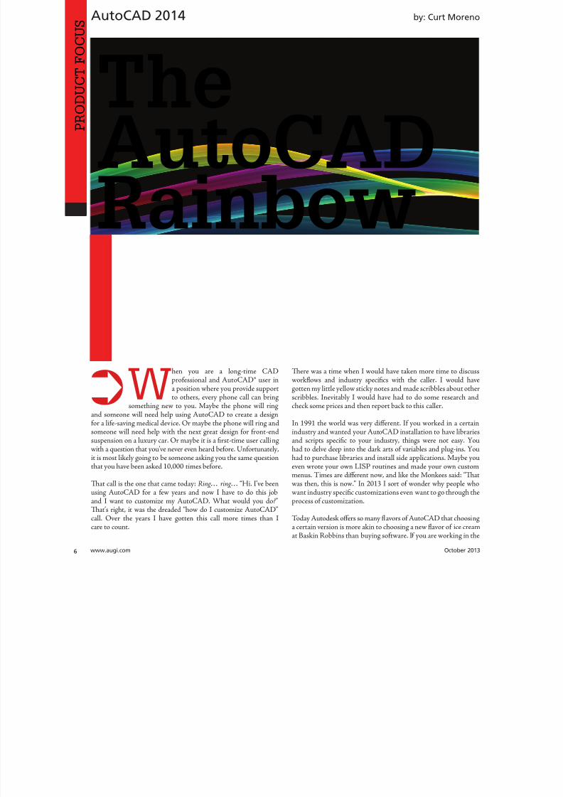
8122019 augi world 2013 10
httpslidepdfcomreaderfullaugi-world-2013-10 652wwwaugicom October 20
AutoCAD 2014
PRO
DUCT
FOCUS
by Curt Moren
When you are a long-time CADprofessional and AutoCADreg user ina position where you provide supportto others every phone call can bring
something new to you Maybe the phone will ringand someone will need help using AutoCAD to create a designfor a life-saving medical device Or maybe the phone will ring and
someone will need help with the next great design for front-endsuspension on a luxury car Or maybe it is a first-time user callingwith a question that yoursquove never even heard before Unfortunatelyit is most likely going to be someone asking you the same questionthat you have been asked 10000 times before
Tat call is the one that came today Ringhellip ringhellip ldquoHi Irsquove beenusing AutoCAD for a few years and now I have to do this joband I want to customize my AutoCAD What would you dordquoTatrsquos right it was the dreaded ldquohow do I customize AutoCADrdquocall Over the years I have gotten this call more times than Icare to count
Tere was a time when I would have taken more time to discuworkflows and industry specifics with the caller I would hagotten my little yellow sticky notes and made scribbles about othscribbles Inevitably I would have had to do some research ancheck some prices and then report back to this caller
In 1991 the world was very different If you worked in a certa
industry and wanted your AutoCAD installation to have librariand scripts specific to your industry things were not easy Yohad to delve deep into the dark arts of variables and plug-ins Yohad to purchase libraries and install side applications Maybe yoeven wrote your own LISP routines and made your own customenus imes are different now and like the Monkees said ldquoTwas then this is nowrdquo In 2013 I sort of wonder why people whwant industry specific customizations even want to go through tprocess of customization
oday Autodesk offers so many flavors of AutoCAD that choosia certain version is more akin to choosing a new flavor of ice creaat Baskin Robbins than buying software If you are working in t
TheAutoCAD
Rainbow
8122019 augi world 2013 10
httpslidepdfcomreaderfullaugi-world-2013-10 752October 2013 wwwaugiworldcom
AutoCAD 2014
civil engineering field then AutoCADreg Civil 3Dreg is the AutoCADfor you For those in the utility market AutoCADreg Utility Designis your choice Te list goes on but more on that later rulytodayrsquos modern AutoCAD has fulfilled the promise of a ldquoplatformrdquorather than a single product
Rather than spending this ldquoCustomizationrdquo issue of AUGIWorlddiscussing the endless ways in which you are able to outfit AutoCADwe are going to discuss the variety of AutoCAD packages on themarket All the software packages we will look at share not onlythe AutoCAD engine but also the interface Soon it will becomeobvious why I feel that patching plugging and twisting standardvanilla AutoCAD is not as necessary as it once was
AUTOCAD CIVIL 3DTe first AutoCAD variant we will look at is the one that I use
just about every single day AutoCAD Civil 3D Although Civil3D is a very close cousin to AutoCAD it is packed with tools androutines germane to civil engineering projects made for design anddocumentation Whether your infrastructure project is a retention
pond a neighborhood subdivision or a major highway Civil 3Dhas the tools for you
With features such as survey data collection and advanced gradingCivil 3D is stuffed full of just the types of tools civil designersneed Major features include advanced surface modeling functionscorridor design and modeling parcel design and advanced stylemanagement Tere are even newly enhanced tools for pipenetworks that include both pressure and gravity systems
As a long-time AutoCAD Civil 3D user I cannot imagine takingthe standard version of AutoCAD and customizing it to better
suit the needs of a civil engineering office
AUTOCAD ARCHITECTUREOne of Autodeskrsquos flagship products is the Autodeskreg Revitregcollection of programs Over the past few years Revit hasbecome the de facto standard in nearly every architecture officein the country With the increasing popularity of the BuildingInformation Modeling (BIM) concept Revit has spread evenfurther into adjacent disciplines As wonderful as Revit is inthe eyes of many CAD users it lacks one major feature theAutoCAD interface
Because Revit is a completely separate product from AutoCADit does not share the AutoCAD engine or interface Tat can be astumbling block and cause a steep learning curve for transitioningCAD professionals Never fear Autodesk has just the solution forthe CAD professional seeking to customize the tried-and-trueAutoCAD installation for a more architecturally oriented taskAutoCADreg Architecture
From the simplest sections and elevations to the most complexmaterials schedules and renovations AutoCAD Architecturebrings all the tools the AutoCAD professional needs to tackle theproject And all of it is powered by the familiar AutoCAD engineand features the familiar interface
Users moving from standard AutoCAD to AutoCAD Architecturewill begin making short work of just about any architecture taskWith enhanced tools for placing walls doors and windows layoutswill happen faster than ever Room documentation and advancedtagging and annotation features along with the industry-standardbuildingSMAR system Industry Foundation Class will makesharing work with others quick and easy
Going from AutoCAD to AutoCAD Architecture will helpexperienced users move from standard drafting to completearchitecture plan sets and rendering quickly and easily Check thisprogram out before digging around the Internet looking for a set
of pre-made door blocks to use
AUTOCAD MECHANICALAnother important product for Autodesk is Autodesk InventorregYou have no doubt heard of this powerful program but may havethought ldquoIrsquom too far into my career to move from AutoCAD tosomething newrdquo o that I would first say ldquoYoursquore never too oldrdquoSecondly I would take a moment to understand that feeling (wersquoveall been there) and tell you to check out AutoCADreg Mechanical
Designers working on a wide variety of mechanical projects willwelcome the features AutoCAD Mechanical has to offer Whetheryou are tired of drawing tension springs or you need some helpdetermining the perfect design for rotation pattern of your camyou are going to find a tool to help you here
Why would you take the time to find blocks even dynamicblocks or bolts or threads or any of that AutoCAD Mechanicalcomes with a multitude of tools that are perfectly suited for thissort of work Sporting a robust library of more than 700000discipline-specific parts and shapes support for multiplestandards and intelligent dynamic geometry this is a packageready to do some work Of course all of this sits atop the familiarAutoCAD interface
TODAY AUTODESK
OFFERS SO MANY
FLAVORS OF AUTOCAD
THAT CHOOSING A
CERTAIN VERSION ISMORE AKIN TO CHOOSING
A NEW FLAVOR OF
ICE CREAM AT BASKIN
ROBBINS THAN BUYING
SOFTWARE
8122019 augi world 2013 10
httpslidepdfcomreaderfullaugi-world-2013-10 852wwwaugicom October 20
AutoCAD 2014
PRO
DUCT
FOCUS
AUTOCAD ELECTRICALIt seems that one of the largest groups of users I meet looking tocustomize their AutoCAD installations work in the Electricalfields Whether it is a small contractor trying to find an economicalroute or a large outfit looking to retool I pose this question ldquoWhydonrsquot you check out AutoCADreg Electricalrdquo
Like all AutoCAD-based products AutoCAD Electrical is aproduct intended for both design and documentation Tat meanselectrical designers are going to find the tools they need all in onepackage that has the familiar AutoCAD interface and commandsin addition to many industry-specific functions Whether you arelaying out panels or bringing together your bill of materials thereis something here for you
One of the common (but unloved) tasks I hear electrical designersand CAD professionals discuss is creating Programmable LogicControls AutoCAD Electrical offers the automation and dynamiclogic that makes this sort of job much easier Not only willelectrical designers be able to choose from a prepared library of
more than 3000 PLC IO modules they can create their own PLCIO modules with the Module Builder tool Tat one feature aloneis enough to save any electrical designer or CAD professional froma head full of gray hair
Documentation tools are just as robust in AutoCAD Electrical asthe design tools Out of the box your designer or CAD professionalis going to be armed with automated report generation features tocreate bills of material terminal plans wire labels and much moreProbably just as fantastic is the fact that you can run reports on asheet a panel a section of design or just about any other selectionyou can need
Sure you could piece together all this sort of functionalityyourself You could go out and download modules and blocksfrom manufacturer sites or purchase plug-ins with similarroutines Ten you could do the installation and compatibilitydance but why AutoCAD Electrical is ready for the electricaldesigner or CAD professional now requiring no more effort thanto install it
THE REST OF THE RAINBOWWe have taken a look at three of the AutoCAD-based productsthat I point people to most often Te wonderful part is that thereis still a whole slew of products out there built on the AutoCAD
platform Users seeking to customize their AutoCAD installationwith model-based GIS tools PampID libraries or structuraldetailing documentation reports just need to check out the rest ofthe impressive collection of AutoCAD-based products
bull AutoCAD Architecture ndash for architectural layouts elevationsand other projects
bull AutoCAD Civil 3D ndash for all manner of civil engineeringprojects from roads to water systems
bull AutoCAD Electrical ndash for electrical distribution projectsbull AutoCAD Map 3D ndash for adding mapping and GIS data to
support planning projects
bull AutoCAD Mechanical ndash for a wide variety of mechanical amanufacturing projects
bull AutoCAD MEP ndash for adding mechanical electrical aplumbing documentation to building projects
bull AutoCAD PampID ndash for design and documentation in pipidesign projects
bull AutoCAD Plant 3D ndash for the 3D layout and design of proceand manufacturing facilities
bull AutoCAD Structural Detailing ndash for creating shop drawinfor steel and concrete structures
bull AutoCAD Utility Design ndash for the rules-based design anlayout of electrical distribution systems
THE END OF THE RAINBOWAs you can see there is wide variety of predesigned industrspecific flavors of AutoCAD From laying out processing facilitto bringing electrical water or sewer services to that facility therean AutoCAD out there for you If you are like me and many othCAD professionals I know you will probably find that selectione of these versions of AutoCAD is much quicker easier an
often cheaper than taking the time to search out purchase ainstall various plug-ins for a standard AutoCAD installation
While there are certainly other Autodesk products that performany of these functions they are not AutoCAD-based and whave different interfaces Tis change in user interface and produdesign can often bring a steep and unwanted learning curve tofirm or project By choosing an AutoCAD-based product you wnot only be adding specific functionality you will also be able benefit from the familiar AutoCAD design and user interface
So the next time you are considering taking the time to customiyour standard AutoCAD installation with various librariscripts or plug-ins think about the alternatives ake a mometo investigate the world of AutoCAD products that are readand available to serve your industry-specific needs You may surprised at how much benefit the rainbow of AutoCAD versiocan bring to your company
Based in Houston exas Curt is aCAD Coordinator for a civil engineer-ing firm and the owner and editor ofthe Kung Fu Drafter blog He beganusing AutoCAD with Release 10 and
has spent the past 20+ years workingwith various Autodesk products includ-ing AutoCAD Civil 3D Map 3Dand SketchBook Designer Curt is alsoa freelance content creator featuredAutodesk University speaker andtraining content developer In his sparetime Curt writes games and spendstime with his dog and horses
8122019 augi world 2013 10
httpslidepdfcomreaderfullaugi-world-2013-10 952October 2013 wwwaugiworldcom
AutoCAD 2014
And Herersquos theExpress Toolhellip
to Find the Settingsfor Variables
Variables come in two flavors (if you donrsquot count those thatare lsquoRead Onlyrsquo) Tose that are saved in the Drawing andthose that are saved in the Registry For example the variableCURSORSIZE is saved in the Registry Te variableEXSIZE is saved by Drawing
But what about the less obvious ones Did you know theOSMODE variablemdasha Registry settingmdashstores a bitcodethat represents the combination of Osnaps you have set Wersquollactually be covering that tidbit in my 90-minute Lab at Autodesk University this year ldquoClick My Ride Customizing AutodeskregAutoCADreg for How You Workrdquo
SYSTEM VARIABLES EDITOROn the Express ools tab gtools panel click System Variables
Terersquos a field at the top that acts as a search feature and thataccepts wildcard characters of for a single character and
for everything before and after Enter MODE to find everyvariable with the word lsquoMODErsquo in it
A bonus feature is the ability to Save All the variables to a SVFfile that you can then read into another system Love this thing
Michael E Beall (B Arch) is an AutodeskAuthorized Author and the owner of CADrainer Guy LLC He has been present-ing onsite CAD training around the plan-et for more than 30 years Contact him atmichaelbeallcadtrainerguycom or givehim a call at 5025002267
8122019 augi world 2013 10
httpslidepdfcomreaderfullaugi-world-2013-10 1052wwwaugicom October 20
AutoCAD Architecture 2014
PRO
DUCT
FOCUS
by Melinda Heavr
Renovation Mode in AutoCADregArchitecture 2014 easily identifies objectsand associates them with different phasesof a renovation project allowing for clear
construction drawings each and every time Younow have the ability to display existing demolished and newconstruction all in one drawing Working within one drawingand having the ability to switch between renovation plan typesallows you to avoid errors that are typically caused by editingmultiple drawings
ACTIVATING RENOVATION MODETe first time Renovation mode is activated a specific Renovationdisplay configuration is created Once activated you will noticethat this specific configuration is a copy of the existing displayconfiguration with ldquoRenovationrdquo added as a prefix (see Figure 1)
o begin Renovation Mode click the Manage tab of the ribbonStyle amp Display panel Renovation Mode Tis brings up the FirstActivation of Renovation Mode dialog box that allows you togive a name to the new display configuration Please note that itis best to maintain the default prefixes for display configurationsto eliminate confusion later Next select the Options button to
change settings using the Display Layers and Styles Blocand Materials tabs Click OK and you are now working Renovation mode
WORKING IN RENOVATION MODEWhen you begin Renovation mode the existing category is assignto existing objects Objects that are added to the drawing while yoare working in Renovation Mode are automatically categorized New If objects are deleted they are assigned to the demo categorhowever they are not actually deleted For example moving a do
Efficiencywith
RenovationMode
Figure 1 First activation of Renovation Mode dialog box
8122019 augi world 2013 10
httpslidepdfcomreaderfullaugi-world-2013-10 1152October 2013 wwwaugiworldcom
AutoCAD Architecture 2014
will create a new door as well as a demo door alongwith the corresponding wall openings It is importantto note that existing and new walls will automaticallyclean up after each other while in Renovation Modehowever demolition and new objects do not interactTis will be discussed more later in the article
In the display configuration for Renovation objectsare displayed according to their display representationWithin this display configuration Existing Newand Demolished categories are specified Tey can beviewed in plan elevation and section displays Both 2Dand 3D objects will display according to the categoriesthey are assigned in plan elevation and section viewsDimensions are important to mention here aswell When you use AEC dimensions you cannotautomatically ignore objects by Renovation categoryAll existing demolished and new objects aredimensioned Any undesirable dimensions must bemanually removed
Objects can be manually assigned to a Renovationcategory if needed Te display properties will changeaccording to the category specified Tis option maybe necessary for 2D multi-view block or block objectsbecause these objects are automatically assigned tothe Existing category when you begin a Renovationsession o do this click the Assign Existing AssignNew or Assign Demo buttons according to yourneeds Next select the objects to be assigned to thespecified category and hit Enter
o make things easier you can click the Select
Existing Select New or Select Demo buttons on theRenovation panel of the ribbon if you have severalitems to work with at once Once selected you cancomplete a command such as Delete
RENOVATION MODE SETTINGS
FOR OBJECTSDesign rules for New Demolished and Existingcategories by object type are controlled by Renovationstyles You can import Renovation Styles fromexternal catalogs or export to external catalogs inthe Renovation Options dialog box For maximumflexibility Renovation styles for display and layerassignment can be specified independently from eachother and are saved to the current drawing
In the Renovation options dialog box the Display taballows you to specify the Renovation Display Style aswell as to set specific design rules for objects such aswalls and doors (see Figure 2) Te layer tab allowsyou to set the Layer Assignment Style and to specifya prefix or suffix to layers in lieu of changing the layername (see Figure 3) Te Styles Blocks and Materialstab allows you to add a prefix or suffix to styleblock
Figure 2 Display options
Figure 3 Layer options
8122019 augi world 2013 10
httpslidepdfcomreaderfullaugi-world-2013-10 1252wwwaugicom October 20
AutoCAD Architecture 2014
PRO
DUCT
FOCUS
names to avoid naming conflicts between objects in differentRenovation categories (see Figure 4) Tis is much quicker thanhaving to manually rename each object When the DuplicateMaterial Definitions box is checked a copy of the material isautomatically generated and assigned to the building object Tecorresponding color settings will automatically display
ENDING A SESSION IN RENOVATION
MODEOnce you are finished working in Renovation Mode endingthe session is simple On the Renovation panel click the CloseRenovation Mode tool It is important to note that if changesare made to the drawing after Renovation Mode has ended theuncategorized objects are automatically assigned to the Existingcategory when you reactivate Renovation mode
MODIFYING THE RENOVATION DISPLAYYou can change how properties of objects within specific categoriesare displayed in the drawing by unlocking them changing themindividually per object type and saving them as the Renovationdisplay style Modifications made are saved to the current drawingTe lock icon to the left of the property signals whether thisproperty can be changed If the property is unlocked any changesmade to the display are reflected in the drawing
With the Renovation drawing open in an active Renovation modeclick Options on the Renovation panel Te Renovation Optionsdialog box displays On the Display tab select the display style toapply to the current drawing and enter a description Renovation
styles can be modified and saved deleted and imported fromexported to an external catalog Now select the object type fthe design rules and then select the checkbox to the left of eaproperty value for the category you want to change Modify tproperties as desired and select Prompt for objects to updatSelect the objects to modify or press Enter to select all objec
Changes to the selected properties for the specified objetype are applied in the current drawing
CONTINUING TO WORK IN
RENOVATION MODEWhen Renovation Mode is reactivated in your drawing texisting Renovation display configuration can still be used you can create a new one Te objects that were previouscategorized in an earlier Renovation phase will retain therepresentation and category Any objects that do not yhave a Renovation category will be automatically categorizand displayed as Existing objects Te ldquoShow existing neand demolished objectsrdquo option is automatically selected default It is recommended that this option remain selecteas it ensures that categorized objects in your Renovatioplan remain visible while switching between the DemolitioRenovation and Revision displays
o continue working in Renovation Mode select the Manatab on the ribbon then click the Style amp Display panand finally click Renovation Mode Tis will display tRepeated Activation of Renovation Mode dialog box (sFigure 5) Next you will need to specify the settings in tdialog depending on what you want to do o begin with existing Renovation display configuration click the drodown arrow next to Activate an Existing Renovation Displ
Configuration select the display you wish to use and cliOK o begin with a new display configuration select t
Create a New Renovation Display Configuration Named buttoenter a name for the new configuration and click OK Next yocan change the display style or design rules of objects by clickinthe Options button at the bottom left of the dialog box Click Owhen finished Ten click OK again to exit the dialog box You anow working in Renovation Mode again
Figure 4 Styles Blocks and Materials options
Figure 5 Repeated activation of Renovation Mode
8122019 augi world 2013 10
httpslidepdfcomreaderfullaugi-world-2013-10 1352
AUGI Members Prepare for the Future of Design
Join industry experts and design visionaries for 3 intensive days of classes andconversations on this yearrsquos hottest topics ndash 3D Printing BIM Cloud ServicesPLM Reality Capture and more
AUGI Highlights at AU 2013
bull AUGI Day Join the scavenger hunt and win great prices
bull AUGI Annual meeting and Beer Bust Get informed on AUGIprograms and planshellipand end the day with a cold brew
bull AUGI Top DAUG Contest Show your cerebral prowess the grandprize winner receives a free AU 2014 pass and HP notebook
bull Come visit the Community Pavilion on the Exhibit Floor to meetyour fellow professionals from the International Communities
Register starting September 12 2013 at httpauautodeskcom
Autodesk University 2013December 3-5 2013The Venetian Hotel Las Vegas
8122019 augi world 2013 10
httpslidepdfcomreaderfullaugi-world-2013-10 1452wwwaugicom October 20
PRO
DUCT
FOCUSAutoCAD Architecture 2013
ACTIVATING A DEMOLITION PLANTe display of a demolition plan shows existing construction andthose objects categorized as demolished All new objects howeverare hidden Display settings for the demolition plan type arelocated in the options dialog box for Renovation Mode
o create a demolition plan activate Renovation Mode as
previously discussed and then select the button for DemolitionPlan on the Renovation panel of the ribbon You can now selecta Renovation Display Configuration to activate Te box next toHide All New Objects is automatically checked If you want Newobjects to show while you are working in the drawing click in thebox to deselect the item and then click OK You can also click theNew ShowHide button on the Renovation panel You are nowready to begin creating a demolition plan
Please note that yellow is automatically assigned by default todemolition objects Tis can be changed in the options dialog boxfor Renovation mode under the Layer tab
ACTIVATING A REVISION PLANA revision plan displays new and existing construction objects butall demolition objects are hidden automatically Display settingsfor the revision plan type are located in the options dialog box forRenovation mode
o create a renovation plan activate Renovation Mode as previouslydiscussed and then select the button for Revision Plan on theRenovation panel of the ribbon You can now select a Revision
Plan Display configuration to activate Te box next to HiAll Demolished Objects is automatically checked If you waDemolition objects to show while you are working in the drawinclick the box next to deselect the item and then click OK You caalso click the Demo ShowHide button on the Renovation panYou are now ready to begin creating a revision plan
MANUAL MODIFICATIONSSometimes walls of different renovation categories do not intersecorrectly so manual modifications become necessary Tis can bdone by temporarily suspending Renovation mode For exampyou may have a plan that includes walls categorized as demolitioand walls categorized as existing with wall edges that need to corrected Remember objects categorized as New do not interawith objects categorized as Demolition When you need to maka manual correction you temporarily interrupt Renovation moby freezing the walls you want to modify and then correcting thedges Tese changes are not considered part of Renovation Toption to freeze or thaw walls is only available when Renovatiomode is active
Letrsquos make this a little clearer o do a manual modification clicthe Freeze Walls button on the Renovation panel of the ribboNext select the walls in question and hit Enter Renovation mois now temporarily suspended Proceed with correcting the wedges and then click Taw Walls when finished Renovatiomode resumes
RENOVATION STYLES CATALOGTe Renovation styles catalog contains display and layassignment styles AutoCAD Architecture-based styles for objecare managed with Style Manager By default the Renovation styl
catalog is installed in ProgramDataAutodeskACA ltversiongtenuStyles If the Renovation styles catalog is renamed or movethe styles are disabled and cannot be accessed Use the RenovatiStyles Catalog Settings dialog box to specify a valid catalog
With the Renovation drawing open in an active Renovation modclick Styles Catalog from the Options drop-down menu on tRenovation panel Te Renovation Styles Catalog Settings dialbox displays Select the Import renovation styles from catalcheckbox for drawings to be populated with all Renovation stylin the specified catalog Clear the Import renovation styles frocatalog checkbox for new drawings to include standard styles onlBrowse to the location of the Renovation styles catalog you wa
to use Click OK
Melinda Heavrin is a CAD Co-ordinator amp Facility Planner forNorton Healthcare in LouisvilleKentucky She has been usingAutoCAD Architecture since re-lease 2000 Melinda can be reached
for comments and questions atmelindaheavrinnortonhealthcareorg
Figure 6 Demolition dialog box
Figure 7 Revision dialog box
8122019 augi world 2013 10
httpslidepdfcomreaderfullaugi-world-2013-10 1552October 2013 wwwaugiworldcom
Inventor 2014by Mark Flayler
F
ree Autodesk Inventorreg apps You meanlike a Bloominrsquo Onion at Outback Countme in Wait you mean Inventor apps asin applications that change how Inventor
works for me and makes me more productive OkayIrsquom still in but I also still want some fried food
In this article we will take a look at severalof the free apps available in the AutodeskInventor Exchange store for trial purchase andSubscription customer benefits
DESIGN CHECKERTe first one we will take a look at is the DesignChecker that was previously called Validus and
sold through DMSI Autodesk purchased thissoftware in a manner similar to its purchaseof the iLogic code from Logimetrix a coupleyears ago Luckily I was a user back before thisacquisition so I know the tool pretty well Tefact that the software went from costing around$3000 to being a free tool delivered exclusivelyto Subscription customers is a really nice benefitfor having an Autodesk subscription right now
Te Inventor Design Checker is a productivitysolution that gives the designer insight into the
adherence of company or customer standards for
the product being designed Live Checking gives instant feedbackto the user and ensures a high level of quality for the entiredesign process
Users can use pre-defined checks or define custom checks withiLogic scripts to perform design checking Executing the on-
10 AppExchange
Reviews
Figure 1
8122019 augi world 2013 10
httpslidepdfcomreaderfullaugi-world-2013-10 1652wwwaugicom October 20
Inventor 2014
PRO
DUCT
FOCUS
demand checking updates the design checker results and enablingthe live-checking allows users to get the real-time feedback fromthe design checker during design process Te Design CheckerResults ree Browser allows users to interactively edit the objectswith failed checks and a Design Checker Results Report shows allthe passed and failed check results and allows users to export thereport to Excel Word or pdf or print the report
Now what I really enjoy about this tool is the iProperty checks andsome of the modeling checks Te machining checks I could livewithout mostly due to the fact that most companies try not to hireusers who make such drastic mistakes in machining operationsMy favorite thus far is the unconstrained sketches check thatvalidates my design before adding it to Vault I have also usedthis as a measuring stick before hiring new engineers or bringingvendor Inventor models into my design
AUTODESK REMOTETis next app allows some really nice RDP usefor Autodesk Inventor Autodesk Remote is astandalone application for Microsoft Window7 and 8 and is compatible with all Autodeskproducts It lets you drive Autodesk softwareinstalled on your primary computer from aremote computer or iPad for fast access to nativedesign data over standard networks o use itsimply install Autodesk Remote on the PC you
want to share Install it again on the machine youwant to connect from and start your connectionNote Autodesk Remote currently works only inNorth America
Autodesk Remote also has a companion applicationfor the iPad that allows you to access your hostPC from an iPad Te iPad app is optimized forAutodesk Inventor so you can work from anywhereimproving collaboration and increasing flexibilityDownlaod the iPad app from the Apple Store
Te controls in the iPad app are pretty easy to understand bthat doesnrsquot make a high-end CAD product made for the Pinstantly translatable to a touch interface You can see wheinterface elements of Inventor have started to lean more towarthis inevitable progression though
From my usage of the iPad app on my iPad 3 I found the usagelittle sluggish and gesturing a bit picky I found the use the ES
Figure 2
Figure 3
Figure 4
Figure 5
8122019 augi world 2013 10
httpslidepdfcomreaderfullaugi-world-2013-10 1752October 2013 wwwaugiworldcom
Inventor 2014
key a mandatory function as I often initiated one navigation tooland found myself trying to start something else before finishing thetool I was in In the end I see some fantastic usage on the horizonfor this app but right now it is pretty gimmicky for my taste I dopicture myself at some point on my front porch with my tabletinstead of my computer I would look cooler to the neighborhoodkids too
Be aware you will probably have to troubleshoot the setup of thisapp a bit I had to lock and unlock my computer and restart theapp several times before I got it just right
FEATURE RECOGNITIONTe Feature Recognition application converts neutral 3D CAD
models such as SEP SA or IGES solids into full-featuredAutodesk Inventor models Feature mapping could be executedautomatically or interactively as needed to maintain design intentCurrently there is one Automatic Feature Recognition commandand eight feature recognition commands you can use
Automatic Feature Recognition attempts to recognize specificfeature types and populate the browser tree with the recognizedfeatures A dialog box displays the feature types you can recognizein the Features section with the defaults checked You can selectfeatures you want to recognize and deselect features you do notwant to recognize
When you import a file it will offer to start feature recognition Ifyou decide to do it later you will have to find your Base1 solid inyour tree and right click on it to start it again
Tis tool has been around for a long time previously only on
Autodesk Labs Personally I donrsquot like it mainly because I have toconstrain and dimension the sketches when they get recognized bythe tool If your goal is to bring in a solid and then do some minormodifications to it then you are better off using the Edit Solidtools also shown in the image above If you want Work Plane toolsalso remember to turn off the Import into Repair Environment aswell before opening the file
If you really had to go the distance and recognize features it isactually a lot quicker and generally creates a more intelligentmodeling history if you just redo it yourself in Inventor Terecognition tools only lend themselves to simple parts inmost cases
Figure 6
Figure 7
Figure 8
Figure 9
8122019 augi world 2013 10
httpslidepdfcomreaderfullaugi-world-2013-10 1852wwwaugicom October 20
Inventor 2014
PRO
DUCT
FOCUS
WORK FEATURE VISIBILITYTis product allows Inventor users to manage all work featurevisibility in a fast and easy way keeping full awareness of the involvedentities Tis app consists of six buttons on part environment andanother six on assembly environment Inside of part environmenta user can choose to enable or disable the visibility property ofplanes axes or points Inside of assembly environment a user can
also choose on which components to enable or disable the visibilityproperty of planes axes or points
I had a little trouble with this app in the assembly environmentbut that was due to some bad installation files Tis is one appreally worth the $099 How often have you been in an assemblyand not wanted to go back to the part files to turn on and offwork features I recommend ungrouping them so you access bothcommands faster
SHEET METAL FLAT EXPORTTere seems to be a plethora of these apps on the Exchange witheach of them varying in price and options In general the ideabehind these apps is to help automate the process of getting a DXF
to a machine that reads them for manufacturing in a more efficientmanner Tese programs will scan an assembly file and find thesheet metal files on which to perform their routines
Te different variations of this program range from free trialsupwards of $100 for the paid apps I started with one that gave me
a ldquoliterdquo version that would do 20 sheet metal files and I liked it much I started using the full version
FEATURE MIGRATORTe Feature Migrator tool allows Inventor users to more eascreate part features from assembly features User can migraassembly features either by selecting them in the Feature Migratbrowser or by right-clicking on one or several of them and theusing the ldquoSend to Partsrdquo commands Features can also be directmigrated from the regular Inventor model browser using thcontext menu item added by the add-in
Once the operation of migrating features is completed the FeatuMigrator displays a dialog that provides information about thresults Tis first dialog is a ldquohigh-levelrdquo report of the migrationprovides the opportunity for the user to select the action to takfor all the assembly features migrated Suppress if SucceedeSuppress always Delete if Succeeded Delete always or Nothingalso for the part features that havenrsquot been migrated correctSuppress Delete or Nothing Features created by the add-in cbe in an invalid state in the parts for a number of reasons
Te user can also see when a feature is out of date from thassembly and perform updates from the part side
Figure 10
Figure 11
Figure 12
8122019 augi world 2013 10
httpslidepdfcomreaderfullaugi-world-2013-10 1952
8122019 augi world 2013 10
httpslidepdfcomreaderfullaugi-world-2013-10 2052wwwaugicom October 20
Inventor 2014
PRO
DUCT
FOCUS
TIME STAMPime Stamp is an Autodesk Inventor add-in that provides bull A low-cost simple-to-use tool that adds plot time information
to your printsbull A plot stamp that does not dirty the Inventor drawing
documentbull
A simple dockable user interface that keeps out of the way
Te ime Stamp editor lets you size position and orient thestamp relative to the adjacent sheet edges You can include datetime and current user information in the stamp Te time stamponly appears on the plot it does not alter the Inventor drawing
What I really like about this app even though it costs $500 perlicense is that you can find the price yourself and buy it It doeseverything it says it does and it provides an easy-to-use interfacewith an icon that changes based on whether the tool is on or offIf you want even more control over your plot stamping there is amore professional version offered by this company on their websitefor about $4000 a license which will allow more reporting fieldsand more control on the look and location of the stamp
SIMPLE SHEET SETTINGSSimple Sheet Settings combines the existing sheet settings withsome new tools such as changing the title block and also the abilityto make changes to all sheets in a document at once
Instead of first deleting the existing title block from a sheetexpanding the title block folder and inserting the desired titleblock then opening another window to change the sheet size andorientation just click the ldquoSettingsrdquo button located on the Sheetspanel in the Placed Views tab (right next to ldquoNew Sheetrdquo) andhave access to all those options in one location
When the Simple Sheet Settings window is loaded it gathers all the existing title block names and puts them into one drop-dowmenu o change the title block on the current sheet simply selethe desired title block from the drop-down menu and click OKTere is also the ability to change the title block sheet size ansheet orientation to all sheets at one time
Tis is a great little app that saves clicks and only costs a dollaQuite useful and no real setup involved
INTERACTIVE TUTORIALTe Create an Interactive utorial app provides instructions fcreating your own interactive Inventor tutorial Te Guide alincludes how to customize the Welcome Screen to display yointeractive tutorial and add to the ribbon
Tis one definitely falls under the ldquotoo much time on your handuser or CAD admin After reading through the guide on how create the interactive tutorials you find yourself asking the questioldquoWhy donrsquot I just save videos of the process we use in a companserver locationrdquo And that is when you uninstall this app as yohave realized that while it sounded good to you at first there abetter ways to accomplish the goal of company-specific tutoria
and process documentation
Figure 16
Figure 17
8122019 augi world 2013 10
httpslidepdfcomreaderfullaugi-world-2013-10 2152October 2013 wwwaugiworldcom
Inventor 2014
Te tools actually rely on too much externally controlled softwaresuch as Camtasia and other plug-ins and third-party apps to makeit work correctly Save your time and just use Camtasia from
echsmith to do your bidding
KEEPING UP TO DATEWith all these apps it is easy to understand how a user could getbehind on the updates to so many tools With that in mind theExchange Manager found on the ools tab in Inventor will keeptrack of that for you and offer assistance not only in updating butalso uninstalling and specialized help for each app
As a reminder with regard to third-party apps if you startexperiencing undesired effects in Inventor start turning add-ins
off one by one until you isolate which one is giving you fits Properreporting back on the app to the developers makes everyonehappier when the issue gets resolved Tus far I havenrsquot had nearas many issues as I thought I would have
ANY MANY MOREWith 80+ apps currently in the store and about 60 of them ready
for 2014 at the time of this article you should take some time andlook through what is available Tere are apps which are very nicheto the user base as well as those that have you scratching your headover why they are not already part of the core software Below aresome I would write about if I had more room in the article andora fatter PayPal walletbull BOM oolsbull EDM Expressbull Sketch Symbol Librarybull SolidWorks iProperty Importbull Quick Viewsbull 3D Pipebull Point Linkerbull Kwikools
Mark Flayler is an application engi-neer with IMAGINi echnologiesspecializing in manufacturing environ-ments He has implemented Autodeskmanufacturing products within severalindustries including the blowinjectionmolding automotive and custom ma-chinery markets When not providingtraining support and implementationhe writes the IMAGINi Manufac-turing Blog and takes an active role inthe manufacturing community Markis an AC certified instructor and isPSE and AC certified in AutoCADAutoCAD Mechanical AutoCADElectrical Autodesk Data Manage-ment and Autodesk Inventor
Figure 18
Figure 19
8122019 augi world 2013 10
httpslidepdfcomreaderfullaugi-world-2013-10 2252wwwaugicom October 20
SPECIALFEATUREAUGI Forums by Melanie Perr
The AUGI Forums are as always a busyplace Ask a question and you mightsee half a dozen varied methods andworkarounds posted in a single thread If
you have not had any questions yourself I would stilllike to encourage you to pop into the Forums and see
if there are any problems you could solve especially if you use one
of the less adopted products Tere will always be many helpinghands in the AutoCAD and Revit Forums but what about themechanical products or design visualization or structural detailingForums Peek in and see if you can share your experiences andwisdom with the community
I confess that I only scoured the English-speaking Forums forcontent for this article but please keep in mind that there areAUGI Forums available in 12 other languages so users have theoption of asking for support in their native tongue
AUTOCAD ndash SYSTEM VARIABLE
DISCUSSIONhttpbitly15M1hB9
Tis topic started out when a user couldnrsquot delete Te solution wasultimately the PICKFIRS variable but the discussion evolved tosafeguarding other variables automatically just to protect against aloss of settings in the event of a crash User Coloradomrg offeredthe safeguard shown in figure 1
Norton_cad also suggestsDIMLFAC EXPER andBLIPMODE be addedto the list
REVIT ndash
UNDERLAY
BEHAVIOR
EXPLAINEDhttpbitly15M1iFd
Mschroeder opened thediscussion with If you haveever wondered why some wallsdonrsquot show up in underlays or
show up inconsistently from floor to floor or why roofs and vieranges affect their behavior then read on
First rule of underlays Underlay view extent properties (cut rangdepth) are not user modifiable and not coupled to any othviewrsquos properties
Itrsquos also been mentioned ldquoIf objects are visible in the view ranof your current view AND in the view range of your Underlathey are automatically hidden in your underlay so there isnrsquotdouble instancerdquo
Users twiceroadsfool and dbaldacchino helped clarify the effecby posting sample models and pertinent data from the AutodeKnowledgebase and Autodesk Support Visibility View RangDetail Level and Cut Planes are all touched on in this discussioNeed clarity on how to make the most of Underlays Check inthis thread on the Forums
LISP ndash MAKING A DIALOG BOX RETAIN
ITS SELECTIONShttpbitly15JzMCc
Te LISP Forum always has such fascinating topics it is hato decide which to highlight From locking OSNAP options setting Explode options along with troubleshooting of existincode But the discussion surrounding the tutorials and metho
to retain selectioin a dialog box wvaried and lively so had to check it ou r e a v e s 0 4 4 1 3 2 1
even posted a sampdcl file when he wfinished
String Theory
8122019 augi world 2013 10
httpslidepdfcomreaderfullaugi-world-2013-10 2352October 2013 wwwaugiworldcom
AUGI Forums
AUTOCAD ELECTRICAL ndash LINES BEING
LABELED AS WIREShttpbitly1ew9p9D
Dinochrome says that one of his coworkers has reported aproblem with regular AutoCAD lines being labeled as wires
Crosswire35 advises ry checking your wire type edit dialogbox and make sure the ldquomake all lines valid wiresrdquo checkbox is unchecked
And IMCO goes on to say Using the vanilla line command inACADE will still place that line on a wire layer Change your linesto layer 0 and ACADE will not give them a wire number
AUTOCAD STRUCTURAL DETAILING ndash
TUTORIALShttpbitly17kW7cc
Te consensus is that this product is a little confusing to figure outand that most of the tutorials out there are older Most productshave a few videos floating around on Youube but this one doesnot seem to have too many yet
Jpo82 chimes in with I guess only tutorials forthis software are those found at Autodesk websiteTey are for versions 2010 and 2011 but still validhttpusaautodeskcomadskservlet12ampid=13111928 Irsquom not sure but sometimes I feel that the only new feature inASD 2013 is that itrsquos more stable than previous releases
Lucis29 goes on to say Also you might check some movieshttpwwwrobotofficecomasd but they are very old
Spenner then linked to his reporting of the Service Pack andissues it addressed hoping that it addressed some of the issuesthat came up in this discussion
NAVISWORKS ndash IMPROVE ANIMATION
EXPORT QUALITYhttpbitly1fQLoIv
Different methods are discussed from exporting individual imageframes to exporting a video (and how long) but I will leave youwith the following list from Revit For Breakfast
Here are the secrets to movies in Navisworks1 Donrsquot use materials ndash you make your render time much longer2 Use the PNG export option 15fps3 Make your video export twice as long as you need Ten speed it
up for a faux 30fps Tis is faster4 Look up the Navisworks blog by Lee Mullin and Paul Walker
about gooch and phong Tere is your faux render setting5 If you have NW 2012 you wonrsquot have gooch or phong but you
will have better export options 2013 has gooch and Phong butfewer export options
6 Te flickering occurs when multiple shapes overlap If you care
delete them in your export model Sometimes flickering occurs
in the generation of your frames on the PNG export You mayhave a frame that is ldquooffrdquo
7 Set your anti-aliasing to 4x or better on the png export8 Check out my old post httpforumsaugicomshowthread
php132209-Animation-Resolutionampp=1138298ampviewfull=1post1138298
CAD MANAGEMENT ndash NETWORK DRIVE
CHANGED BY IT WITHOUT WARNINGhttpbitly18J4k9c
Blackbox advises edinsmore595165 straight off to utilize theReference Manager program that comes with AutoCAD inorder to reconnect all of the external reference paths that werebroken when the I department upgraded their archaic serversHe further points out that moving from hard pathing to relativepathing would make things easier in the future
Feargt offers another twist Another option which would workon a need only basis when you open the specific drawing Change
XREF and Image paths in drawing to Network path throughscript on a need only basis Basically this will only change pathsPlace this line in a acaddoclsp file(command ldquoscriptrdquo ldquoyourserver and pathXREFREDIRECscrrdquo)and the following in a script fileREDIRB enter name of path to be replacedP enter new path
Tere was also a debate in this thread about obstacles and benefitsof user-managed and I-managed drive mapping
Melanie Perry is a Facilites-Manage-ment Coordinator and echnical Edi-tor in St Louis MO She is the AUGISalary Survey Manager and is curring-ly serving as an Officer on the Board ofDirectors Melanie can be reached atmistressofthedorknessgmailcomor found on witter asMistresDorkness
OTHER HOT TOPICSHave you found a Forum solution so mind-bogglinglyuseful that you leapt out of your chair with a whoopingcheer (or were at least tempted to) Please let me know Asingle person cannot read every post in our bustling AUGIForums so if you would like to see a thread highlighted ina future edition of String Teory feel free to let me knowSend me Wanderer a PM in the Forums or send an emailto MelaniePerryaugicom
See you on the Forums
8122019 augi world 2013 10
httpslidepdfcomreaderfullaugi-world-2013-10 2452wwwaugicom October 20
Revit Architecture 2014
PRO
DUCT
FOCUS
by Martijn de Rie
Myth Buster
Revit amp IFCPart 3
Irsquove given a lot of thought as to how this trilogyof articles should end At first I thought Irsquoduse the Coordination View 20 EXPRESS-GWallPaper for IFC2x3 (httpwwwmdr-
adviesnlwp-contentuploadsCoordinationView_V2-0_WallPaper_IFC2X3_Version-1pdf ) as a stepping stoneto give an ldquoIFC for Dummiesrdquo type of solution But that turnedout to be quite lengthy and rather boring But the link is includedabove for obvious reasonsmdashitrsquos useful
So I went back a little and asked myself ldquoWhy IFCrdquo And with thatquestion the inevitable follow-up immediately appeared ldquoWhynot IFCrdquo I realized that in the previous articles I failed to explainwhy in my humble opinion we should care about this somewhatcrooked badly implemented severe headache-inducing formatTerefore instead of explaining the fundamental technicalities ofIFC that can be explored in other places this final installment willexplore the Why versus Why Not IFC discussion and begin withthe latter
WHY NOT IFCWhen everybody uses Autodeskreg RevitregWell in this case itrsquos a no-brainer Share your Revit files Period
Loss of dataTis is an easier way to share data instead of hacking your wthrough IFC and praying your stuff doesnrsquot get lost in the proce
Even when you manage to export your geometry through IFtherersquos always loss of data
Loss of intelligence during importEven if you only need to send over geometry not data importithat into Revit makes it utterly useless All constraints are locomponent parametrics are gone and so on
Availability of bidirectional linksWhen not everyone uses Revit on a given project (which is quoften when yoursquore not located in the US) why not simply ua bidirectional linking between proprietary software standardTis can be easier and better to control
8122019 augi world 2013 10
httpslidepdfcomreaderfullaugi-world-2013-10 2552October 2013 wwwaugiworldcom
Revit Architecture 2014
WHY IFCWhich may be asked as why would you want to use IFC Or moreaccurately why would you want that option available
Consider what Sir Arthur Conan Doyle wrote ldquoOnce you eliminatethe impossible whatever remains no matter how improbablemust be the truthrdquo
Letrsquos put that to the test shall we
When everybody uses RevitOkay simple math Autodesk has around 7000 employees Teworld has about 72 billion people What are the chances someonenot working for Autodesk has a brilliant idea and creates thesoftware you need tomorrow Tere will always be better solutionsTey might not be viable for you overall but therersquos no reason toshut down access to them Revit is a wonderful generic tool forwhich I see a brilliant future with all kinds of additions for specificniche-markets like AutoCAD has
What about today DDS is MEP-engineering software that cando energy calculations (not simulations) inside your modelRhino lets you model things on the fly that could (arguably)take ages in Revitmdashif you ever get them done ekla lays wasteto the Revit structural rebar functionality any day of the weekwithout breaking a sweat Solibri is a wonderful solution for clashdetection and most importantly rule-based model checking andreportingmdashsomething Revit (or Navisworks) doesnrsquot do
Should I go on
Only problem for all this magnificent software Itrsquos either based onthe IFC format or requires model exchange through IFC
Te fact of the matter is there will always be better softwareAny one may be the software for you but that doesnrsquot mean yourpartners associates etc need to have the choice to use it forcedupon them
Loss of dataOn July 1 2013 there was an extra release for Autodesk softwareTe Sourceforge Open Source IFC Exporter released a new versionthat incorporated the option to map custom Revit parameters(shared or non-shared family or project even calculated values) totheir IFC counterparts
On September 28 2013 I had the honor of showing the secondstep in a complete and controllable data export from Revit
During my RC Europe class I showed the new option to create acustom IFC Property Set and map any given Revit parameter intoIFC fully customizable
IFC does not automatically lead to loss of data Tat idea is simplynot true Incomplete implementation in Revit does lead to loss ofdata As of now you are able to put any piece of data into an IFCeven calculated values And we didnrsquot change the IFC format We
just improved implementation in Revit
Loss of intelligence during importldquoJust because something hasnrsquot happened yet doesnrsquot meanitrsquos impossiblerdquo
I donrsquot know who originally had this insight and I doubt it to bethe movie line I remember but it is true
In the same RC Europe class I showed a native Revit familybeing exported to IFC altered and re-importedmdashwhile keepingall parametric constraints and even adjusting to the alterationsmade directly in the IFC file It is possible but not with thecurrent importer
Availability of bidirectional linksIrsquove been using Revit for almost 10 years now For 4-5 years I didnrsquotknow about IFC at all Before a year ago this was my strongestargument against IFC Why would you need a generic ldquolanguagerdquowith all its limitations (of which there are) weaker implementationand use of parametric capabilities (because it has) and lag-times indevelopment (by nature)
IFC will never be able to do what native software does simplybecause itrsquos responsive in nature Development budgets are afraction of what Autodesk rimble or Nemetschek get to spendon their software
So why not keep it simple and use a bidirectional link Revit has itwith a lot of other Autodesk software and third-party applications
But how long have we waited for them And are they even trulybidirectional Do they exactly do what you want them to do In myhumble opinion the answer to these questions is not very inspiringEven bidirectional links tend to have major limitations and severe
constraints in flexibility And most important Te link itself isalso propriety software No way of adjusting it to your needs
WHAT IF MORE PEOPLE STOPPED
TALKING ABOUT IT AND JUST GOT
INVOLVEDTe improbableFirst off itrsquos a matter of simple logic As Sir Arthur suggested ifwe can successfully check off all likely options to NO want touse IFC doesnrsquot that mean the improbable is true Tat IFC is infact a valuable tool in our toolkit and we should be able to use it
when necessary
Mind you Irsquom not saying you should use IFC If yoursquore on a Revit-only project it would be insane Just send and receive RVs Tefact is this will only be viable for limited parts of the buildinglifecycle If yoursquore lucky the entire design team is on Revit Butmanufacturers have other software facility managers too
As for the design team what if the best structural engineer is not[on Revit] or the MEP guy that has loads of experience in similarprojects Would you settle for second-best just because someoneuses the same brand of tools you do I wouldnrsquot
8122019 augi world 2013 10
httpslidepdfcomreaderfullaugi-world-2013-10 2652wwwaugicom October 20
PRO
DUCT
FOCUS
Revit Architecture 2013
Open AccessWhich brings us to the biggest advantage of IFC (or any open
format) itrsquos open Which means itrsquos adjustable to your needs Nowdonrsquot go ldquothatrsquos too difficult expensiverdquo Tatrsquos bullocks
Te first external enhancement to the Open Source Exporter wascreated by om Pesman a self-employed API specialist
Parametric IFCImplemented by Jon Mirtschin also self-employed IFCparametrics is available Agreed Jon is a well-known IFC guru butstill the point holds
Custom property sets and parametersWim as owner of a small MEP engineering firm hasadded functionalities toward this end and hersquos not even a trueAPI specialist
All these developments were done for free by altruistic volunteerefforts as part of the creation of the Dutch Revit Standards Andof course with the invaluable help of the Autodesk Open SourceIFC Exporter team Angel Velez in particular
But what if these guys actually got paid What if this projectwasnrsquot a Saturday night side-job What if more people stoppedtalking about it and just got involvedmdasheither by themselves or byleveraging experts to get what is needed Te entire IFC format is
Open Source the source code is out there which basically meansyou can do whatever you want and create whatever you needmdasheven on a project-by-project basis
BIM ITrsquoS THE ldquoIrdquo THAT MATTERSIn my humble opinion the entire debate on BIM is focusing on thewrong part of the acronym I donrsquot care if ldquoBuildingrdquo is a noun ora verb Nor do I care whether itrsquos ldquoModelrdquo or ldquoModelingrdquo nor am Icommenting on whether one should say ldquoBIM Modelrdquo
Itrsquos the ldquoIrdquo that matters If wersquore collaborating the Informationis most all I care about I just want your datamdashin the leanest
smartest and most effective way possible
A Revit model will do conversely a lot of times A Revit model w
give me heaps of data I donrsquot want geometry I donrsquot care about ana file format I canrsquot use Now we can all keep on being really anabout it or we can simply use the tools available to us one of thebeing IFC
A FINAL NOTEAs stated at the beginning of the article I really enjoyed writinthis series and for now this is the last of the series But if yoursquointerested in more tips and tricks on IFC let me know I might able to persuade the guys at AUGI to let me write about it againLord knows there is still a lot to talk about regarding IFC
Martijn de Riet is a self-employedBIM Consultant from the Nether-lands working with Revit since version51 Martijn has a bachelor degree inBuilding Science After his studieshe started his own engineering firmworking for contractors architects and
private clients Starting in 2007 hiscompany transformed into a full-timeBIM consultancy service At the mo-ment Martijnrsquos clients vary from mid-sized architectural firms to the largest
dutch General Contracter and MEPEngineering firms with a focus onspecific corporate solutions design andimplementations of Revit and BIMworkflows Martijn is a member ofthe Dutch Revit User Group and cur-rently working on creating a Masteremplate and Component LibraryHe provides lectures for companiestechnical universities seminars etc ona regular basis
Itrsquos the ldquoIrdquo that matters If wersquore collaborating the Information is most all I care about I justwant your datamdashin the leanest smartest and
most effective way possible
8122019 augi world 2013 10
httpslidepdfcomreaderfullaugi-world-2013-10 2752
wwwxicomputercom
8122019 augi world 2013 10
httpslidepdfcomreaderfullaugi-world-2013-10 2852wwwaugicom October 20
3ds Max 2014
PRO
DUCT
FOCUS
by Chris Murra
SUMMARY WHATrsquoS
CUSTOMIZABLE IN MAX
(HIGH LEVEL)When it comes to the customizability of Autodesk 3ds Maxregitrsquos no secret that it can morph itself into whatever you want theprogram to become
Whether yoursquore a modeler animator lighter rigger generalist ortechnical artist 3ds Max can become your own personalized toolbox that is an extension of your own hand in your daily workYou can now combine different command types (such as creatingobjects and object modifiers) into a single menu reducing themouse travel and improving efficiency
In this article wersquore going to take a closer look at one specificaspect of customization with 3ds Max the new enhanced UI Aspart of this article besides taking a deep dive into the operationof this feature I will also be showing how I created the ldquoMographrdquo
tools UI that includes custom buttons and icons At the end this article I will also provide a link to this UI so you can use customize it yourself or share it with others
ENHANCED UI SUMMARYWhat is the Enhanced UI
Te Enhanced UI is a new graphical user interface system thdoes two main things
1) It provides a refreshed 3ds Max user interface with updattool categories and new clusters of pre-existing tools in groupinthat are more akin to their intended purpose as opposed to somtechnical requirement for menu placement
2) It provides a way to allow you the end user to customize thmenu system in almost any way you choose Te drop-down menare ldquotear-ablerdquo (not to be confused with ldquoterriblerdquohellip but I digresand the resulting configurations are savable either by scene or
3ds MaxEssentialsCustomizing
the UI
8122019 augi world 2013 10
httpslidepdfcomreaderfullaugi-world-2013-10 2952October 2013 wwwaugiworldcom
3ds Max 2014
a preset Tey are also distributable and deployable so they can beshared with others
Where is the Enhanced UITe Enhanced UI can be found in the upper left hand corner of themain UI at the very top of the screen Tere is a drop-down menuthat says ldquoWorkspace Defaultrdquo Tis default is the same baselineUI that ships with all 3ds Max installs (Figure 1)
Within the drop-down you can find the ldquoDefault with EnhancedMenusrdquo Tis is the alternative default menu system that youcan use on its own or use as a starting point to create your owncustomized menus
BASIC DEFAULT CUSTOMIZATIONEnhanced UI Customization BasicsNow that wersquove enabled the Enhanced UI how can we change it
SOP Before you begin mucking around with the UI Itrsquos importantto understand what I call the ldquosave-logicrdquo as it pertains to custom UIs
Te UI Save LogicIf you plan on saving this UI for future use there is a specificmethod you must follow to properly save the UI you want and notwreck the default Enhanced UI
Te Save Logic is as follows Itrsquos simple but important
Step 1 urn on Enhanced Default UI (Figure 3)
Step 2 Click ldquoSave as New Workspacerdquo FIRS At this point youwill be prompted for a new name (Figure 4)
Step 3 Edit and change the UI at will
NOE All future edits are ldquoautomatically rememberedrdquo as you go (Iintentionally did not use the word ldquosaverdquo)
Step 4 Te ldquosave as default staterdquo button is important When wehave completed the customization process we then choose thisbutton to ldquolockrdquo in the changes Tis is different than Saving a UIwith a custom name
HO IP ldquoBut this methodology seems backwardrdquo
I can see how yoursquod say that but remember that any changes you make
to any enhanced UI are automatically ldquorememberedrdquo If you create acustom UI then while working you make some temporary changeswhen doing something specific those little changes are automaticallyremembered If you want to return to the default state [of yourcustomized UI] you select ldquoReset to default staterdquo Tis does NObring back the default Max UI rather it brings back the customizedUI you created in ldquolockedrdquo in Step 4
Okay now that you have the save logic down letrsquos begin customizing
1) If you havenrsquot done so already turn on the Default Enhanced UI
2) Go to ldquoManage workspacesrdquo from the drop-down and in the
Figure 1 Workspaces are in the Workspace drop-down menu
Figure 2 Default UI (left) and the Default Enhanced UI (right)
Figure 4 Saving the New UI Workspace
Figure 3 Turning on the Enhanced Default UI
8122019 augi world 2013 10
httpslidepdfcomreaderfullaugi-world-2013-10 3052wwwaugicom October 20
3ds Max 2014
PRO
DUCT
FOCUS
Manage workspaces dialog choose ldquoSave as new Workspacerdquo Giveit a specific name
3) Begin making your desired changes
Since a custom UI is specific to any one individual letrsquos take a lookat what types of customizations can be made
Simple ChangesOne of the simplest things to do is peel off any commandgroup (see Figure 5) Just click the group title bar and drag Tecommand group becomes a floating dialog box Now just becauseyoursquove peeled it off does not mean that yoursquove removed it fromthe drop-down menu Te ldquooriginalrdquo command group remains inthe drop-down You can just close the floating dialog when yoursquoredone with it
Probably the simplest thing you can do is reorganize the menusIn each drop-down menu appears a group of commands You maynotice that some command groups are icons and some are words(Figure 6) o change the appearance of the commands there is asmall icon in the upper right corner of each group of commands(Figure 7)
Te next change is alreally simple Is tcommand group op(expanded) or clos(rolled up) Just clion the plus or minsign in the upper le
corner to set this stafor the next time yolaunch 3ds Max (Figu8) Remember thesettings are saved as yogo so whether it is opor closed is your choicbut the state the menis in when you cloMax is the one that remembered the netime Max opens
What about Saving tDefault state More othis later
Once you have floating menu yocan combine differecommand groups dragging any othcommand group to aother floating dial
that yoursquove created Tis makes for easy creation of custom dialo
based on specific tasks Figure 9 shows a command group fcharacter animationFigure 5 A floating menu that has been torn off the drop-downmenu
Figure 6 The different display states of the menus
Figure 7 Changing menu layouts
Figure 8 Rollouts
8122019 augi world 2013 10
httpslidepdfcomreaderfullaugi-world-2013-10 3152October 2013 wwwaugiworldcom
3ds Max 2014
ADVANCED CUSTOMIZATION
What about completely custom interfaces Herersquos how we do thatwith the Enhanced UI menu system
Te following is the high-level overview of the process Wersquoll thenunpack each step in more detail
If you havenrsquot read the section on Basic default customizationplease do so before continuing Before starting this phase ofcreating your new UI you should have saved your new UI stateTat process is explained in the previous section
1) Create a main drop-down menu (like ldquoMy oolsrdquo)
2) Create a tools category menu into which you will place yourtools (a submenu such as ldquoModeling oolsrdquo or ldquoAnimation oolsrdquo)Drop-downs can have more than one subcategory
3) Add commands to various submenus
4) Clean up the UI by creating custom names adding separatorsor creating custom icons
First letrsquos create a new menu for the menu bar Tis is done easilyfrom the CustomizegtCustomize [Rollout]gtCustomize UserInterface dialog box
Steps for Creating a Drop-Down Menu1) Create a New Menu and give it a name (see Figure 10)
2) Locate your new menu in the Menus window It will be listedalphabetically (Figure 11)
Figure 9 Multiple command groups in one menu
Figure 10 ndash Creating a new drop down menu
Figure 11 Location of new menu
8122019 augi world 2013 10
httpslidepdfcomreaderfullaugi-world-2013-10 3252wwwaugicom October 20
3ds Max 2014
PRO
DUCT
FOCUS
3) Drag your newly created menu category over to the column onthe right Tis will add your new drop-down menu to the interfaceimmediately and you can begin populating it with menu items (seeFigure 12)
UI DESIGN IP Te actual menu name and display name can bedifferent I used a custom menu name behind the scenes so I couldeasily differentiate my menus from the ones created by default or other
tool companies After you create a menu and add it to the right column you can right-click on it and change its display name (see Figure 13)
Next letrsquos create a command group1) Just like in Step 1 from the previous section create a new men
2) Tis time before you drag it to the right column click thplus sign next to your drop-down menu item to expand it Tedrag the new item to the right column dropping it ldquounderrdquo thmenu name
3) Drag any commands from the Commands window on the leto the submenu on the right (see Figure 15)
Herersquos an example from my Mograph ools workspace thshows how a completed menu looks once it is created (Figu16) In the following figure you see both the menu as it appeain the Customize UI dialog and the actual menu (which has bepeeled off)
Notice that some of the commands on the menu are greyed ouTatrsquos because this new menu combines both ldquoObject creatcommands and ldquoObject Modify Commandsrdquo in one menTey will remain grey until you create an object on which thwill be used
Figure 12 Adding the new menu to the UI
Figure 14 Creating a command group
Figure 15 Dragging commands onto the menu
Figure 13 Custom menu names
8122019 augi world 2013 10
httpslidepdfcomreaderfullaugi-world-2013-10 3352October 2013 wwwaugiworldcom
3ds Max 2014
Adding SeparatorsSeparating commands is easy and is recommended to help you oryour intended user make sense of the how the tools are arranged inthe menu Creating a separator is as easy as dragging one over theright column just like a menu or command
HO IP ldquoWhy do I need to create another menu Why canrsquot I addtools right to my menurdquo
Te main reason is that adding a submenu gives you the ability to tearoff the submenu If it werenrsquot in a submenu it wouldnrsquot be tear-ableSo itrsquos really a ldquobest practicesrdquo kind of thing But even if you try to notadd the submenu it will happen automatically Itrsquos important to do it
explicitly so you are aware of what submenus are in the menu and that you are the one in control of what command is going where
CUSTOM ICONSNo custom UI is complete without a custom set of iconsAdditionally not all commands in 3ds Max have their own iconyet But itrsquos important to realize that regardless of how you set up
your UI yoursquore still working within the framework of an existingapplication and there are boundaries to what you can edit andcreate Icons have specific requirements both in their creation(size) location and file name that must be adhered to in order forthem to work properly
SizeformatTe size of icon is pretty simple It must be 32x32 pixels andPNG format
LocationTe location is very specific New icons must be added to thislocation
CProgram FilesAutodesk3ds Max 2014UI_lnResourcesDarkIconsMain
Te new icons I created for the Mograph UI are shown inFigure 17)
Icon File NameIf yoursquore still with me at this point we are now getting into thenether regions of customizing a UI Tis is where things get a littletricky but itrsquos really not too bad File names are specific and aregenerated by the application (3ds Max)
So letrsquos begin First identify the command for which you want aniconmdashusually itrsquos one that doesnrsquot already have an icon But if itdoes and yoursquore changing it MAKE A BACK UP of the originalicon PNG file Tis is because as previously stated you donrsquot havecontrol over the file name Tat means if yoursquore creating your ownicon you need to overwrite the existing one and use its name foryour new icon So back up any original icons
Figure 16 The completed menu
Figure 17 ndash The created icons
8122019 augi world 2013 10
httpslidepdfcomreaderfullaugi-world-2013-10 3452wwwaugicom October 20
3ds Max 2014
PRO
DUCT
FOCUS
It really doesnrsquot matter whether you make the icon first or not ofind the name you need to use you need to navigate as follows
NOE Yoursquore about to edit the ribbon Tere is no need to save thesechanges as we are merely extracting information from it But if yoursquoredoing a lot of custom icon work you may want to save this change to theribbon so you can come back and continue your work in later sessionswithout have to recreate this every time just to get the proper file nameSaving this ribbon is not related to saving your default state of yourUI When yoursquore done creating all your UI icons you can just delete
whatever changes you make to the ribbon
1) Open the ldquoCustomize Ribbonrdquo dialog box
2) Create a new ldquotabrdquo by dragging it onto the ldquoExisting Ucolumn in the middle (see Figure 18)
3) Using the same drag method add a new ldquopanelrdquo to ttemp tab (Figure 19)
4) Now you can get the information you need Find tcommand for which you are creating an icon and dragto the panel
5) Locate the ldquoinfordquo portion of the ldquoPreview Windocolumn At the bottom of the column is the file namneeded to have the icon used properly by the applicati(Figure 20)
CONCLUSIONSo now you know how to create a custom UI scheme f3ds Max 2014 and up By using the Enhanced UI me
system itrsquos really easy to generate a multitude of workspathat allow Max to work the way you want to work
Te example used in this article was the ldquoMographrdquo UI thI created for NAB 2013 If you would like to downloand install it you can get it from my ldquoPinning the Stacblog on the Area herehttpareaautodeskcomblogschrismurray
Enjoy
Chris Murray works for Autodesk
Media amp Entertainment He istrained as an animator (3D variety)but considers himself a creative tech-nologist His daily role is a technicalldquoevangelistrdquo for Autodesk creating marketing deliverables for 3ds Max Heis the author of Mastering 3D StudioMax He has a Masters in Fine Arts(MFA) in Computer Animation fromMiami International University of Artand Design Follow him on witterchrismmurray
Figure 18 Creating a tab on the ribbon
Figure 19 Adding a panel to the tab
Figure 20 Finding the required file name
8122019 augi world 2013 10
httpslidepdfcomreaderfullaugi-world-2013-10 3552
AUGIMembersReach Higherwith ExpandedBenefitsAUGI is introducing three new Membership levelsthat will bring you more benefits than ever beforeEach level will bring you more content and expertiseto share with fellow members plus provide anexpanded more interactive website publicationaccess and much more
MEMBERMEMBER MEMBER
Basic members haveaccess tobull Forums
bullHotNews (last 12 months)
bull AUGIWorld (last 12 months)
DUES Free
Premier members haveaccess tobull Forums
bullHotNews (last 24 months)
bull AUGIWorld (last 24 months)
DUES $25
Professional members haveaccess tobull Forums
bullHotNews (full access)
bull AUGIWorld (full access and in print)
bull ADN 2013 Standard Membership Offer
DUES $100
Are you ready to upgrade yourself and your membership
Access additional benefits and upgrade at wwwaugicom
8122019 augi world 2013 10
httpslidepdfcomreaderfullaugi-world-2013-10 3652wwwaugicom October 20
AutoCAD MEP 2013
PRO
DUCT
FOCUS
by Vladimir Triantafillid
BIM IsWhatrsquos
Driving theIndustry
For the past decade many would arguethat building information modeling(BIM) has metastasized aggressivelythroughout the AEC industry but what
does BIM really mean More importantly whatdoes it do for us and for our industry Ask someone who hasbeen in this industry for more than 25 years or those nearingretirement and yoursquoll find that less than half see its value muchless care to make the effort with its implementation hesequestions mean something different for those who have beenin the industry the past 10-15 years Recent college graduates
however with their tech-savvy capacity and high expectationare eager to implement anything that resembles cutting-edgflashy technology ypical ly they are the ones most receptivenot adamant about putting their talents to use through BIM
I recently gave a BIM presentation with an emphasis on mchanical systems to the summer interns and new hires our companymdashall were non-BIM users except for onemdashbmy presentation did little justice to BIM Half of my audence had found a cure for their insomnia when they realizthis wasnrsquot the latest edition of ldquoCall of Dutyrdquo hat was n
8122019 augi world 2013 10
httpslidepdfcomreaderfullaugi-world-2013-10 3752October 2013 wwwaugiworldcom
AutoCAD MEP 2013
reflection on BIM by any measure Simply put I fell shortof connecting with a potentially captive audience eager toknow what really makes BIM intriguing or how it wouldgive them an edge in the industry I didnrsquot think to look pastpresenting the facts of its processes and benefits o simplyhave stated that proficiency in any of its many facets willpromote a lucrative career would give those still awake theimpetus to jump ship In hindsight the first step I shouldhave taken to begin this presentation was to ask what theywanted to get out of BIM
If you think itrsquos hard conveying the value and splendor ofBIM to receptive and impressionable young minds try toconvince the weathered veterans dead-set in their ldquooldtricksrdquo For every experienced veteran who has converted toBIM there are two ldquoold dogsrdquo that canrsquot shake ldquothe good olrsquodays when we used vellum and light tablesrdquo Guess whatmdashanincreasing amount of naysayers are starting to come aroundincluding those who say theyrsquove been burned by BIM in thepast hey are seeing the simple solutions BIM presents and
how these solutions translate into cost savings More andmore of those who had formerly questioned BIMrsquos utility areconvinced when installation efficiencies are not only real-ized but quantified
Another factor in the evolution of BIM is its tendency toexpand faster than the pace of its general population of us-ers hose of us proud to be catching up to what we think iscutting edge quickly realize it was just another false sense ofaccomplishment as BIMrsquos web continues to grow exponen-tially he solution is rather simple Focus on what you canhandle and always have the presence of mind and sense ofcaution to avoid being overwhelmed by the wake of BIMrsquos
progress herersquos plenty of money to be made and countlessfacets to explore as long we have the following mentality Welive in the information age and those wi lling to share knowl-edge will reap the rewards of communal synergy
On the opposite end of the spectrum you might find ourindustryrsquos opportunists In a hurried frenzy to claim theirspot in the intellectual property queue these opportunistsget carried away with pioneering what they assume is the lat-est improvements to BIM Instead of stopping to absorb anddevelop the benefits of 4D 5D 6D and so on the pioneersare spreading these ldquoDsrdquo thin with abandon further expand-
ing the gap between quality and quantity None of this i s tosay that wersquore heading in the wrong direction On the con-trary letrsquos call it more of a positive economic problemmdashthedemand for BIM expertise and development outweighs thesupply of available users
Fortunately as collegiate curricula catch on to this industrytrend the point of equilibrium will soon follow For as longas I can remember respective companiesrsquo 2D CAD depart-ments have been a significant source as the breeding groundfor potential BIM users While this route hasnrsquot changedregarding the career path of a draftsperson the source poolhas expanded to include architects engineers and construc-
tion managers just to name a few Itrsquos even hard not to noticeits stark demand when BIM and Revit courses are being in-creasingly offered at local community colleges I knew thenthat you didnrsquot necessarily need an undergraduate degreeback when I got my foot in the door of this industry hisprobably wonrsquot hold true in the coming years Still the privi-leged few who are already a part of this industry subset canrely on their experience in this fast-paced market to con-tinue to propel their careers forward ever faster All thesefew need to do is grab onto a small piece of BIMrsquos wing andhang on tight for the ride he fresh-out-of-college e ntrantsmight have a harder time grabbing onto this wing thatrsquos al-ready in motion
o those who are only vaguely famili ar with BIM it is typi-cally perceived as the equivalent of a 3D role-playing videogame In this case itrsquos not difficult to capture a ldquosnapshotrdquoimage of a 3D model shadows cast across random metal ob-
jects taking up space in an orderly fashion between ceil ingspaces and walls What is difficult is conveying the abun-dance of value behind the pretty picture to a client whorsquosonly interested in the pretty picture Who isnrsquot familiar withthe adage ldquoa picture is worth a thousand wordsrdquo Why notchange that saying to ldquoa BIM model is worth five thousandhyperlinksrdquo Now wersquore talking lifec ycles and facilities man-
More and moreof those who had
formerly questioned
BIMrsquos utilityare convinced
when installationefficiencies are notonly realized but
quantified
8122019 augi world 2013 10
httpslidepdfcomreaderfullaugi-world-2013-10 3852wwwaugicom October 20
AutoCAD MEP 2013
PRO
DUCT
FOCUS
agement his supposed video game has suddenly becomean encyclopedia of usable information But wait itrsquos not juststatic information thatrsquos stuck on a DVD on a shelf i n someownerrsquos random storage closet It has now become a livingdynamic source of real-time data Maintenance technicianswill know exactly where to go when the active 3D modelloaded on their laptop highlights a hot water pump needingservice while concurrently bringing up the cut sheets andoperation and maintenance manuals specific to that pumpor system Better still the source of information has shiftedfrom multiple stacks of large drawing sets collecting dust toseveral hundred gigabytes on a hard drive Yes Mrs Clientyour 3D BIM model will be usable for the next 20+ years
Even though you might not necessarily think about i t someof you probably realize that BIM has become the ldquomiddle-manrdquo for so many key components in the construction cyclewell beyond its intermediary role between design and con-struction phases You want to do some significant tenantimprovement in an existing building Laser-scan the exist-ing conditions hatrsquos BIM Is the general contractor rackingtheir brain trying to f igure out where to station the crane forthe project or pave the pathways for delivery trucks Nowtheyrsquore looking to BIM to answer these questions and opti-mize their decisions o take it a step further at which endof the building do we want to load thousands and thousands
of pounds of sheet metal and pipe And then which tradesshould be installing their systems first in any given area ofthe building hatrsquos right wersquore deriving sequencing andtimelines from the BIM model to e stablish the best routes totake while addressing any constructability issues BIM hasbecome the consultant that wears most of the hats Itrsquos ourone-stop shop
I know that Irsquove personified BIM as if itrsquos the brains behindall of its success Letrsquos take a moment to focus instead on itscollaborators or the sum of its integral parts to show thatin reality we are Dr Frankenstein and BIM is our monster
Except in our ca se wersquore beginning to ta me our monster anthose who were previously frightened by it are starting to sthat it indeed is no monster In fact while evolving to domdashand becomemdashgreater things BIM is transforming into aindustry hero he point of convergence is approaching bcause wersquore saving money time and even trees Soon enougBIM will be the industry standard even on the smaller proects Letrsquos keep the pedal to the meta l
You want to know the best news Most of us havenrsquot evebegun to scratch the surface of BIM but wersquore in strategpositions to reap the rewards aking the possibility of ivast potential into account isnrsquot it reassuring knowing th
in these tough economic times wersquore engaged in an industthat has a shortage of well-qualified BIM experts Our eposure alone sets us up for success Now ask yourselves thquestion Is BIM driving our industry or is it the BIM use
Vladimir riantafillidis works for aleading mechanical contractor in theSan Francisco Bay Area with morethan 10 years of experience in the in-dustry Although he has a bachelorrsquosdegree in biology his unique careerchoices have firmly rooted him in a
substantial BIM role awarding himthe opportunity of progressing along-side the relentless evolution of BIMOutside of his career hersquos always opento new adventures whether trying anew cuisine exotic travels or extremesports Te latter adventures have re-cently subsided as the balance of lifehas shifted his focus on spending timewith his growing family
You want to know the best news Most of us havenrsquot
even begun to scratch the surface of BIM but wersquore
in strategic positions to reap the rewards
8122019 augi world 2013 10
httpslidepdfcomreaderfullaugi-world-2013-10 3952
8122019 augi world 2013 10
httpslidepdfcomreaderfullaugi-world-2013-10 4052wwwaugicom October 20
Revit Structure 2014
PRO
DUCT
FOCUS
Streamlining
Sheet Listswith a Custom
Application
In this article we take a brief look a simpleadd-in for Autodeskreg Revitreg named X-Sheetswhich provides tools for incorporating sheetsfrom an AutoCADreg sheet set in a Revit sheet
list ypically this is handled by manually addingplaceholder sheets to the Revit sheet list Tis can be problematicbecause the sheet list becomes disconnected from the sourceand must be updated manually With X-Sheets sheet set datais exported directly from AutoCAD linked to a Revit project
and included in the sheet list by automatically addingupdatinplaceholder sheets For this example all structural scheduleplans elevations and section sheets are in Revit Structure Adetail sheets will be pulled from an external AutoCAD sheet set
X-SHEETS RIBBON PANEL Te first command on our ribbon panel is Discipline Tcommand is used to establish the Revit project parameter twhich the AutoCAD sheet subsets will be mapped For th
by Jonathan Albe
Figure 1 Revit X-Sheets ribbon panel
8122019 augi world 2013 10
httpslidepdfcomreaderfullaugi-world-2013-10 4152October 2013 wwwaugiworldcom
Revit Structure 2014
example we have created a project parameter named My DisciplineParameter Each Revit Structural sheet has been assigned a valueof SRUCURALmdashthe same as the subset name for theAutoCAD detail sheets Te sheet list is grouped and sorted bythis parameter
Te next command on the ribbon panel is Links Tis command isused to establish a link between the Revit project and XML file(s)
containing sheet information exported from AutoCAD You cancreate as many links as needed and use relative paths if required
Te next two commands Sheets and Update do the work ofaddingupdating placeholder sheets to the sheet list While theSheets command allows you to select individual sheets from linksto include in the sheet list the Update command includes all sheetsfrom all links
EXPORT SHEETS FROM AUTOCADFigure 3 shows the AutoCAD X-Sheets ribbon panel and asample sheet set containing structural detail sheets Notice thedetail sheets are grouped under a subset named SRUCURALTis subset name can be exported with each sheet and mapped to
the My Discipline Parameter in Revit Figure 3 shows the ExportSheets dialog with an option to include subset information and theability to exclude individual sheets Selecting the Export buttonprompts us with a dialog to save an XML file to be linked into ourRevit project
Figure 2 Discipline command dialog
Figure 3 AutoCAD X-Sheets ribbon panel and sample sheet set
Figure 4 Export sheets dialog
Figure 5 Export complete
8122019 augi world 2013 10
httpslidepdfcomreaderfullaugi-world-2013-10 4252wwwaugicom October 20
Revit Structure 2014
PRO
DUCT
FOCUS
ESTABLISH LINK TO XML FILE IN REVIT
PROJECTFigure 6 shows the Manage Links dialog A link has been added tothe XML file we generated when exporting sheets from AutoCADNotice there is an option to make the link path relative to our
Revit Project location
IMPORT SHEETS FROM XML LINKFigure 7 shows the Revit Structure sheet list before any sheetshave been imported from AutoCAD After selecting the Sheetscommand we are prompted with a Manage Sheets dialog
For this example we have selected all sheets from the XML linto include in our sheet list After confirming the dialog neplaceholder sheets are immediately added to the sheet list angrouped according to the SubsetDiscipline mapping Te neplaceholder sheets are identified behind the scenes as being relatto the X-Sheets XML link for later updating
Figure 6 Manage Links dialog
Figure 9 Sheet list after import
Figure 7 Sheet list before import
Figure 8 Manage Sheets dialog
The X-Sheets
add-in is a great tool
for incorporating
AutoCAD sheets into
a Revit sheet list
8122019 augi world 2013 10
httpslidepdfcomreaderfullaugi-world-2013-10 4352October 2013 wwwaugiworldcom
Revit Structure 2014
UPDATE SHEETSFigure 10 shows the Export Sheets dialog in AutoCAD afterdetail sheets have been renumbered to include ldquo-Ardquo When changesare made to AutoCAD sheets the original export steps must befollowed to replace the XML file linked to our Revit project Oncethe XML has been replaced simply run the Update command inRevit to update the sheet list
SUMMARYTe X-Sheets add-in is a great tool for incorporating AutoCADsheets into a Revit sheet list Te add-in saves time by automatically
adding placeholder sheets eliminates room for error in manualtranslation and helps to keep your sheet list up to date withminimal effort
Jonathan Albert is co-founder of BIM- pulse echnologies LLC amp SeniorApplications Developer at LindemanBentzon Bojack Engineering in Cler-mont Florida He has worked morethan 15 years implementing and usingBIM echnology for some of the na-tionrsquos leading production home build-
ers Most recently he has developedBIMpulse an Options Managementand Material akeoff Add-In for Au-toCAD Architecture Revit and Au-todesk Design Review Jonathan can bereached at jonalbbecom
Figure 10 Export Sheets dialog after sheet renumber
Figure 11 Update complete
Figure 12 Sheet list after update
The X-Sheets
add-in is agreat tool for
incorporatingAutoCAD
sheets intoa Revit
sheet list
8122019 augi world 2013 10
httpslidepdfcomreaderfullaugi-world-2013-10 4452wwwaugicom October 20
AutoCAD Civil 3D 2014
PRO
DUCT
FOCUS
by Tench Tilghma
Itrsquos a fact Jack You invested money in the worldrsquosmost popular civil engineering and designsoftware You (or someone else) will have workhard to make the software run productively
and publish the engineering design or surveywork acceptably
Every AutoCADreg Civil 3Dreg user will tell you ldquoYou need a Civil3D templaterdquo
heyrsquore right sort of You need more than one he suppliedexample Autodesk template files (dwt) are just thatmdashexamplesto show you that things are possible A great many ldquothingsrdquo arepossible in Civil 3D It is data-centric model-based software Asa dedicated content developer and continuous customizer of Civil3D I hope the following perspectives and tips help shorten thecycles and reduce the pain of customizing the software
AutoCAD Civil 3D was constructed from the ground up todisconnect the survey and engineering data from how that missioncritical data is represented
WITH LIBERTY COMES RESPONSIBILITYAs far as Autodesk is concerned what you want the many Civil 3Dldquothingsrdquo to look like and how the Civil 3D data is to be annotated istotally up to you hatrsquos not really true is it Plan sets are publishedin arcane symbolic graphic languages designed to faithfully conveythe design intent to someone who must build it with a plan checkeror two (or three or four) stuck in between
As a professional I prefer to call them ldquoPlan Set Languagesrdquo hhelps focus the development to the publishing of Civil 3D datMost people throw a fuzzy word around this complex mix human perceptive agendas and call that ldquoCAD Standardsrdquo
ldquohe wonderful thing about standards is there are so many of themndash Grace Hopper et al
PICK A STANDARD AND MANAGE BY ITldquoWe already have a CAD standardrdquo his may be the first anworst Civil 3D customization mistake any skilled AutoCAD usor organization can make he odds are the CAD standards yoemployed before do not take into account the data centric anmodel-based methods that Civil 3D employs Simply put Civ3D manages how things look and behave by Style Primitive-basAutoCADreg standards may get in the way
Older ldquoCADrdquo standards by definition must be focused on CAprimitive publishing specifics layer textstyle (height) blo
CustomizeCorrectly
Figure 1 Standards documentation is required
8122019 augi world 2013 10
httpslidepdfcomreaderfullaugi-world-2013-10 4552October 2013 wwwaugiworldcom
AutoCAD Civil 3D 2014
graphics standards and so on In raw AutoCAD and AutoCAD-based drafting and design software the only way to manage all theCAD primitive stuff was to be SPECIFIC about all the details allthe time he drawing we create and check things in is the drawingwe publish
If you publish work out of quality control or design drawingsin Civil 3D this is a sign you may be missing some of its timesaving advantages
While the old CADD process works it requires a lot of man-hoursdedicated to maintaining and checking the details Clearly one ofCivil 3Drsquos critical design development goals is to rid organizationsand Civil 3D users of this expensive man-hour burden and costhe idea here is to put the man-hours into the iterative engineeringprocess instead Civil 3D Feature data and Style make this possible
Civil 3D styles and label styles do employ the AutoCAD layertextstyle block references AutoCAD customizers are used tohe software is still called ldquoAutoCADrdquo Civil 3D after all Our
AutoCAD customization skills still apply But we must applythem differently and much more systematically Herersquos whyhellip
YOU NAME ITmdashTHE MOST CRITICAL
STANDARDCivil 3D Styles and label styles employ (reference) the AutoCADldquonamedrdquo parts to ldquoexpressrdquo themselves Style tools just look for andmatch the ldquorightrdquo names Change the ldquomeaningrdquo andor definitionof the names and you can change anything
We call this fundamental property and benefit of object-orientedprogramming the Power of Names In programming speak this
concept and practical reality is called a ldquonamespacerdquo
Such a namespace in engineering speak answers the questionldquoIn this context does ldquoDIrdquo means a ldquodrop inletrdquo In a minute wersquollget to the structure of a customization ldquonamespacerdquo for Civil 3DAutoCAD references
THE POWER OF NAMESGo ahead and make a drawing from your current Civil 3D templateoss in some Civil 3D data by data reference from any projectUse the RENAME command on any of the old AutoCAD stylecollectionsmdashtry layers
Rename like crazy Your existing Civil 3D styles and label styles willhappily work exactly the same he components in the Civil3DFeature and Label Styles will go to your renamed layers Becauseyou didnrsquot change the properties of the layers either nothingchanges Itrsquos not too exciting until you think about what it means
FOLLOW A SCRIPTObviously as customizers we never want to do this sort of workmanually Computers are faster better and more exact typists thanwe are We commonly rely on AutoCAD scripts generated from
Microsoft Excel spreadsheets (See the end of the article)
here are a couple of key collections in the object model thatCivil 3D walls off from this form of potentially destructiveuser madnessmdashObject Properties in Drawing Settings and afew things like Figure Prefix Dbs values that are not ever in thedrawing per se
WHAT REALLY MATTERSAutoCAD Civil 3D style is mind-boggling abstraction Everythingis designed and built to point at references We can employ styleabstraction for our benefit
In one sense AutoCAD Civil 3D style doesnrsquot care aboutAutoCAD layer standards block libraries textstyles colorsplotstyles or really anything else AutoCAD From our perspectiveall the Civil 3D styles care about are the arbitrary and exact namesthey currently reference
he Civil 3D customizerrsquos dilemma Keep book on the exactnames here are a lot of names to keep track of You must havea plan You must have rules You must employ the same processesconsistently in the same order to get quality assured results
Figure 2 Are description keys a namespace
Figure 3 Rename the AutoCAD reference names
8122019 augi world 2013 10
httpslidepdfcomreaderfullaugi-world-2013-10 4652wwwaugicom October 20
AutoCAD Civil 3D 2014
PRO
DUCT
FOCUS
hat Current word is a wonderfully relative term forthe customizer
Build a set of styles extract them to another drawing rename andor redefine the references and quickly produce a different resulthe Current method makes it easy to propagate success andmistake It makes it repetitively tedious to make fixes
NO CAN STOPAs innovative content developers for Civil 3D we chose to employthe National CAD Standard (NCS) as our fundamental Namestandard Not because we like the NCS but because of all thehard-won experience expressed in these tested standards Inmany respects we employ the NCS UDS (Uniform DrawingStandards) etc in our Production Solution products becauseof the underlying How and Why for those standards and theirpractical published Rules
We want to build faster high-performance vehicles Why reinventthe wheel when we can improve on it
STANDARD KEYS TO NAMEShe NCS employs a hierarchical concept of Keys here areMajor Keys Minor Keys etc that have order precedence and aninterpreted meaning he NCS Layer standard employs the Key-based rules to produce defined meanings to Layers
You can in practice employ the same Layer Keys to be genericor granularly specific about where the published results go Allthe annotation can go to one layer or many different layers forexample Styles andor sets do the work
his KEY CODE structure produces a flexible and structuredldquonamespacerdquo we referred to earlier Itrsquos a namespace that both thesoftware can employ and is relatively easy for us dumb-bunnyhumans to learn to decode when we must Most of the time theusers donrsquot and shouldnrsquot care anyway
Figure 4 shows a few of the NCS ldquolikerdquo Keys we employ in ourproducts We employ them for both layer and block collectionsand even the structure of libraries hey may even be employedin Civil 3D style names when thatrsquos appropriate (See the endof the article)
he customizing key point is that the meanings of these specificKeys can be translated into any other set (or sets) of different
Keys he Key changes can be systematically applied to whatevAutoCAD reference tables and resources we require
he results of any changes will float uphill to the named Civil 3Styles we choose to employ hink of all the AutoCAD referencin a template as a Set
BEYOND AUTOCADNow wersquove looped back to Civil 3D style tools and substantivetheir names and what their parts refer to Welcome to the circuland iterative world that is customizing and employing Civil 3D
Aside from the requisite customization skills and experience build style tools our practical biggest customization issues afrankly Civil 3D human interface issues
No matter how you cut it you have a very limited amount of tespace to help users decide on the ldquorightrdquo style tool to use he teof the style toolrsquos name is all you get to deliver to the user ypicaitrsquos a pick box list
You might get lucky and have the Style Viewer but that Viewcannot represent everything a style can do
FEATURE STYLES NAMESWhat we call the ldquoFeature Stylesrdquo (the Ci3D Featurersquos graphics) require that our stynames explain in simple readable humterms what the tool does For examplesurface style like ldquoContours 1-5 Proposed
Figure 4 Some standard keys
Figure 5 The limitations of user style choice
8122019 augi world 2013 10
httpslidepdfcomreaderfullaugi-world-2013-10 4752October 2013 wwwaugiworldcom
AutoCAD Civil 3D 2014
For the common and most understood features this makes somesense ASCII order rules how named Styles organize Names mustsort that out
Complex graphic features such as Views have a lot more going onldquoMy Standard Profile Viewrdquo doesnrsquot cut it except in a publishingtemplate he style names must be more informative and specificDoes the Profile View include grid lines or not We must recognizethat the engineering data behind what we want to visualize isvariable and the user will have specific needs to get work doneWhen you check a surface you need to see the data in differentways than when the result is published
Choice of style is productive Choice is not contrary to publishingstandards unless you mix the two
LABEL STYLE NAME FACTORSWhen we open the Alignment Label Style collection andorstart to assemble Sets of Label Styles we see any hope of namesimplicity for label styles disappears in a flash
he majority of styles are annotative here are a lot of formsand specific types of them Label Style ype matters he smartcustomizer employs the Label Style Default (LSD) hierarchyexpressed in the oolspacegtgtSettings tab or ignores it and missesthe benefits
Label styles often must have a geometric framework to themItrsquos about ldquoreadabilityrdquo and meaning Whether this label goes upor down or attaches here and not there is critical to annotativeclarity he graphic structure of many data-rich label styles alsofundamentally matters to the stylersquos upgrade stability herersquos
a maintenance cost to pay if you refuse to employ consistentgeometric structures in label styles
CUSTOM USAGECan users see the right data and at the right time Will the useremploy a general alignment parcel or figure line and curve labelHow do they see the difference in a simple list It is easy to misshow ldquoon-the-flyrdquo annotative information negatively or positivelyeffects design time decision making and quality control Peoplewill make things to get the job done Do you fight it or enable ithe Simple Style Rules anyone can learn
THE CIVIL 3D NAMESPACESA Civil 3D style naming convention must be human readablecreate order in the interface and therefore include a rule-basedeasy-to-learn code system that expresses quickly the critical detailso customize we need two namespaces One for the top-end stylesand one for the back-end AutoCAD references In productionprojects we need a third namespace for how we name the featuresbut thatrsquos another story
his client and this project demand these CAD standards specificsAnother client and project demand something different Even ifyou donrsquot believe you regularly face that common problem you
still have to improve the internal production templates themselveshe method and process arenrsquot different
In our project-based production world Civil 3D users andsupervisory staff can always work with the familiar and publishwhat is demanded in a customized publishing template hetwo-pronged project template approach has the added benefit ofpotentially quantifying the costs and real return on investment forthe customization itself
CUSTOMIZE TO PUBLISH ON DEMANDIn practical terms we can change the expressed graphicsmdashthe PlanSet Language (CAD standards) with managed intern level staffEven non-CAD people can see and identify graphic differenceOnly basic AutoCAD and basic spreadsheets skills are requiredfor much of the work if you have a naming plan ldquoChange thatmanhole block to look like this manhole blockrdquo Your ldquothatrdquo mustbe specific
ldquoPublish on demandrdquo capability is a productivity and competitive
advantage but it takes repetitions to develop and practice the skillsWe must endlessly customize Civil 3Dmdashreap the benefits
CIVIL 3D NAME RESOURCEShe Standard Keys the NCS-like AutoCAD reference namespacehe Jump Standards includes the detailed and documented stylenamespace Find them at wwwcadpilotcomresourcesaspx
Excel Cell Formula Script ExampleHerersquos the pseudo code for a typical formula-based layer script thatmakes a layer table with all the details filled in from a cell It createsa series of quote wrapped strings when a column of such cells is
copied and pasted to an ASCII text file
ltLayerCommandgtampCHAR(13)amprdquoSrdquoampCHAR(13)ampltOldLayergtampCHAR(13)amprdquoRrdquoampCHAR(13)ampltNewLayergtampCHAR(13)ampltNewLayergtampCHAR(13)amprdquoCrdquoampCHAR(13)ampltColorgtampCHAR(13)ampCHAR(13)amprdquoLWrdquoampCHAR(13)ampltLineweightgtampCHAR(13)ampCHAR(13)amprdquoPSrdquoampCHAR(13)ampltPlotstylegtampCHAR(13)ampCHAR(13)amprdquoDrdquoampCHAR(13)ampltDescriptiongtampCHAR(13)ampltNewLayergtampCHAR(13)
ench ilghman is President ofMoreCompetency Inc an Autodesk
Developer Partner specializing in in-novative Civil 3D Production Solu-tion products and consulting services
for AutoCAD Civil 3D ench is aregular speaker at Autodesk Univer-sity and AEC industry events on thetopics of technology adoption innova-tion and (his personal favorite) peopleskills He posts on the Get the Jump onCivil 3D blog
8122019 augi world 2013 10
httpslidepdfcomreaderfullaugi-world-2013-10 4852wwwaugicom October 20
Revit MEP 2014
PRO
DUCT
FOCUS
by Todd Shackelfor
W
hen any new technology hits theground there are plenty of false startsand backtracking In time shortcutsare found tricks of the trade are
discovered and best practices are defined So is thecase with Autodeskreg Revitreg even for MEP users his article willoutline a logical roadmap of technical and non-technical mustdorsquos and donrsquot dorsquos for transitioning to Revit MEP From settingexpectations defining goals and plotting in Revit to addressingBIM IPD and VDC the checklist of elements required to helpRevit really work in an office will be covered Every implementationwill come with resistance workflow issues and plenty of headachesbut staying on course and hitting the important milestones alongthe way will help reduce stress of something akin to the craziestfamily trip ever
FIRST CONSIDERATIONS ndash SOFTWAREOne might think it is all about Revit he truth is that Revit reallywants to act as a central location for data that is constantly on themove Much like a smartphone leverages the power of thousandsof applications Revit plugs into workflows with more than a fewAutodesk programs as well as a host of third-party programs hesimple fact that the Building Design Suite comes with so manyvaried applications is a pretty big hint that Revit wants to play ona team Firms need to look at their processes from a high level andlook for the best workflows and programs for the team
FIRST CONSIDERATIONS ndash HARDWAREEvaluate the PCs and know what their capabilities are anknow what Revit requires Search Autodeskrsquos website for systerequirements for Revit products Requirements for three tieof deployment are listed for systems covering an entry-levconfiguration a balanced performance configuration and performance configuration Certified and supported graphi
hardware is also accessible from this page he non-hardwasavvy should seek input from an I professional Revit cannand will not perform on outdated or entry-level PCs and thperson leading the implementation usually takes the blame wheexpectations fall short Best advice is overkill it on hardware Whseems over the top today is inadequate in a year
FIRST CONSIDERATIONS ndash TRAININGhere is no way to get around the fact that training will need tbe done Even if every person in the firm has already used Revtraining on using Revit company standards must still take plachere are many ways to deliver training An in-house expe
TransitionRoadmap
8122019 augi world 2013 10
httpslidepdfcomreaderfullaugi-world-2013-10 4952October 2013 wwwaugiworldcom
Revit MEP 2014
can provide just-in-time all the time Autodesk resellers andconsultants typically provide three- to five-day immersion trainingand short- to long-term consulting here are countless web-based training optionsmdashfree and paid Community colleges thatoffer Revit training usually require a final project that will putstudents through the paces and better entrench the
knowledge and skills
On the down side Revit MEP-specific classes areall but impossible to find Lastly the extreme go-getter can buy a book and learn on the job In realityeveryone learns differently and being preparedto leverage all these types of training is the bestsolution People will gravitate to the solution thatworks best for them when it is provided
FIRST CONSIDERATIONS ndash
LINE UP YOUR DUCTS (UGH hellip
DUCKS)Set appropriate goals based on the size of thefirm Small medium and large firms will havedrastically different goals and timelines It mightseem odd but small firms have the upper hand inadopting new technologies and processes hinkabout it What is easiermdashgetting 3 people toagree or 300 Recognize that an AE firm will havecompletely different goals and processes than a solely MEP firmDuring any shift in process be prepared to support the old andnew at the same time and sometimes in the same project hiswill mean keeping symbols in Revit as close as possible to symbols
in AutoCADreg Consider how quality reviews are done and clientexpectations When things look different it is an impediment tochange Minimizing the impediments will help tremendously
All that being said communication is the real key to most everyprojectrsquos success It is important keep information flowing upand down the chain and set the expectations early Some criticalexpectations for this type of implementation are that things will gowrong things will take longer things will look different things willhave to change and things will continue to evolve Remind usersand management of the progress they have been made by trackingand documenting incremental goals
With a general direction and expectations set itrsquos time to get morespecific about the journey his trip is a long one and a phasedapproach is best Firms can tailor the following phasing to suitindividual needs his example has four phasesmdasheach with itsown goals building off the previous phases
Phase 1 - Goals1 Create construction documents2 Improved collaboration3 Interference mitigationo obtain these goals the following Revit items need to be addressedhe first group addresses the goal of good construction documentshe second group deals with process and keeping things standardhe space available in this article doesnrsquot allow for ldquoHow torsquosrdquo foreach item but each is well documented in the Revit help pageand all over the Internet Get a couple points of view and marrythe possibilities to the culture and needs of the firm in question
bull Line styles createdbull Fonts set for plan text titles title blocks tags and everything
elsebull Object styles ndash Define the weight color tone and transparency
of everything bull Incorporation of standard detailsbull Browser organization ndash Decide how you want to see views
organizedbull Filters ndash Know if you need standard filters and create them
ahead of timebull Phasesbull View templatesbull Project templatebull Duct Stylesbull Pipe stylesbull Family creation
Figure 1
Figure 2
8122019 augi world 2013 10
httpslidepdfcomreaderfullaugi-world-2013-10 5052
8122019 augi world 2013 10
httpslidepdfcomreaderfullaugi-world-2013-10 5152October 2013 wwwaugiworldcom
Inside Track
CSCrsquos Integratorhttpwwwcscworldcom
Integrator is a tool that allows you to synchronize structural designscreated in CSCrsquos Fastrak Building Designer (steel building designsoftware) and Orion (structural concrete building design software)with Autodeskreg Revitreg 2014
ldquoLeading structural software provider CSC has released a new versionof Integrator its market leading Structural BIM integration softwarefor synchronizing code-compliant models produced in CSCrsquos buildingdesign software Fastrak and Orion with Autodeskreg Revitreg Nowfully compatible with Autodesk Revit 2014 structural engineers andtechnicians have even greater control during the integration process
Using Integrator full and part models can be synchronized betweenFastrak or Orion and Autodesk Revit with the ability to manageadded deleted and modified members and their associated
design datardquo
BiMTOOLShttpwwwsofistikcom
BiMOOLS is a set of productivity tools that are designed forAutodeskreg Revitreg 2014 Te plug-in can be installed from theAutodesk Exchange Apps store
ldquoTe first international version of the SOFiSiK BiMOOLS isnow available SOFiSiK BiMOOLS is a collection of free tools forAutodeskreg Revitreg Structure to enhance the productivity up to 50Te features range from easy font type substitution and automaticgeneration of dimensional lines over the automatic positioning ofstructural elements to the comprehensive Family Creator to generatefamilies of eg beams braces and columns for optimal communicationwith FE analysis tools like the SOFiSiK softwarerdquo
Find further information and download links for Revit 2012 and
2013 on the dedicated BiMOOLS website
Autodesk AutoCAD 360 21httpswwwautocad360com
Autodeskreg AutoCADreg 360 is a mobile and web-based application that allows you to view editand share drawing files created with AutoCADand AutoCAD-based products Te mobile appis available from the Apple iunes App Store andGoogle Play Store
ldquoAutoCAD 360 is a free easy-to-use drawing and drafting mobileapp that allows you to view edit and share AutoCAD drawingsmdashanytime anywhere Simplify site visits and fieldwork with powerfuldesign review and markup toolsmdashavailable online and offline
Seamlessly share drawings with others across desktop web andmobile devices Easily access drawings from web browsers using
the free companion AutoCAD 360 web app AutoCAD 360Pro subscription plans further expand the functionality of
the app bringing additional capabilities to the fieldrdquo
Te updates that are in this latest release arebull Stunning high-resolution drawings display
via full retina supportbull Better display through improved PDF
supportbull Easy switching between metric and imperial
unitsbull Saves time with faster app loading bull Improved collaboration through in-app
notifications and streamlined sharing bull New properties for Properties Palette
(Pro version)
AUGIWorldbrings
you recentdevelopmentsin Autodeskand AEC-relatedsoftwareitems
Until next issue
If you have some news to share with us for future issues please let usknow Likewise if you are a user of a featured product or news itemand would like to write a review we want to know
By Lee Ambrosius
8122019 augi world 2013 10
httpslidepdfcomreaderfullaugi-world-2013-10 5252
8122019 augi world 2013 10
httpslidepdfcomreaderfullaugi-world-2013-10 852wwwaugicom October 20
AutoCAD 2014
PRO
DUCT
FOCUS
AUTOCAD ELECTRICALIt seems that one of the largest groups of users I meet looking tocustomize their AutoCAD installations work in the Electricalfields Whether it is a small contractor trying to find an economicalroute or a large outfit looking to retool I pose this question ldquoWhydonrsquot you check out AutoCADreg Electricalrdquo
Like all AutoCAD-based products AutoCAD Electrical is aproduct intended for both design and documentation Tat meanselectrical designers are going to find the tools they need all in onepackage that has the familiar AutoCAD interface and commandsin addition to many industry-specific functions Whether you arelaying out panels or bringing together your bill of materials thereis something here for you
One of the common (but unloved) tasks I hear electrical designersand CAD professionals discuss is creating Programmable LogicControls AutoCAD Electrical offers the automation and dynamiclogic that makes this sort of job much easier Not only willelectrical designers be able to choose from a prepared library of
more than 3000 PLC IO modules they can create their own PLCIO modules with the Module Builder tool Tat one feature aloneis enough to save any electrical designer or CAD professional froma head full of gray hair
Documentation tools are just as robust in AutoCAD Electrical asthe design tools Out of the box your designer or CAD professionalis going to be armed with automated report generation features tocreate bills of material terminal plans wire labels and much moreProbably just as fantastic is the fact that you can run reports on asheet a panel a section of design or just about any other selectionyou can need
Sure you could piece together all this sort of functionalityyourself You could go out and download modules and blocksfrom manufacturer sites or purchase plug-ins with similarroutines Ten you could do the installation and compatibilitydance but why AutoCAD Electrical is ready for the electricaldesigner or CAD professional now requiring no more effort thanto install it
THE REST OF THE RAINBOWWe have taken a look at three of the AutoCAD-based productsthat I point people to most often Te wonderful part is that thereis still a whole slew of products out there built on the AutoCAD
platform Users seeking to customize their AutoCAD installationwith model-based GIS tools PampID libraries or structuraldetailing documentation reports just need to check out the rest ofthe impressive collection of AutoCAD-based products
bull AutoCAD Architecture ndash for architectural layouts elevationsand other projects
bull AutoCAD Civil 3D ndash for all manner of civil engineeringprojects from roads to water systems
bull AutoCAD Electrical ndash for electrical distribution projectsbull AutoCAD Map 3D ndash for adding mapping and GIS data to
support planning projects
bull AutoCAD Mechanical ndash for a wide variety of mechanical amanufacturing projects
bull AutoCAD MEP ndash for adding mechanical electrical aplumbing documentation to building projects
bull AutoCAD PampID ndash for design and documentation in pipidesign projects
bull AutoCAD Plant 3D ndash for the 3D layout and design of proceand manufacturing facilities
bull AutoCAD Structural Detailing ndash for creating shop drawinfor steel and concrete structures
bull AutoCAD Utility Design ndash for the rules-based design anlayout of electrical distribution systems
THE END OF THE RAINBOWAs you can see there is wide variety of predesigned industrspecific flavors of AutoCAD From laying out processing facilitto bringing electrical water or sewer services to that facility therean AutoCAD out there for you If you are like me and many othCAD professionals I know you will probably find that selectione of these versions of AutoCAD is much quicker easier an
often cheaper than taking the time to search out purchase ainstall various plug-ins for a standard AutoCAD installation
While there are certainly other Autodesk products that performany of these functions they are not AutoCAD-based and whave different interfaces Tis change in user interface and produdesign can often bring a steep and unwanted learning curve tofirm or project By choosing an AutoCAD-based product you wnot only be adding specific functionality you will also be able benefit from the familiar AutoCAD design and user interface
So the next time you are considering taking the time to customiyour standard AutoCAD installation with various librariscripts or plug-ins think about the alternatives ake a mometo investigate the world of AutoCAD products that are readand available to serve your industry-specific needs You may surprised at how much benefit the rainbow of AutoCAD versiocan bring to your company
Based in Houston exas Curt is aCAD Coordinator for a civil engineer-ing firm and the owner and editor ofthe Kung Fu Drafter blog He beganusing AutoCAD with Release 10 and
has spent the past 20+ years workingwith various Autodesk products includ-ing AutoCAD Civil 3D Map 3Dand SketchBook Designer Curt is alsoa freelance content creator featuredAutodesk University speaker andtraining content developer In his sparetime Curt writes games and spendstime with his dog and horses
8122019 augi world 2013 10
httpslidepdfcomreaderfullaugi-world-2013-10 952October 2013 wwwaugiworldcom
AutoCAD 2014
And Herersquos theExpress Toolhellip
to Find the Settingsfor Variables
Variables come in two flavors (if you donrsquot count those thatare lsquoRead Onlyrsquo) Tose that are saved in the Drawing andthose that are saved in the Registry For example the variableCURSORSIZE is saved in the Registry Te variableEXSIZE is saved by Drawing
But what about the less obvious ones Did you know theOSMODE variablemdasha Registry settingmdashstores a bitcodethat represents the combination of Osnaps you have set Wersquollactually be covering that tidbit in my 90-minute Lab at Autodesk University this year ldquoClick My Ride Customizing AutodeskregAutoCADreg for How You Workrdquo
SYSTEM VARIABLES EDITOROn the Express ools tab gtools panel click System Variables
Terersquos a field at the top that acts as a search feature and thataccepts wildcard characters of for a single character and
for everything before and after Enter MODE to find everyvariable with the word lsquoMODErsquo in it
A bonus feature is the ability to Save All the variables to a SVFfile that you can then read into another system Love this thing
Michael E Beall (B Arch) is an AutodeskAuthorized Author and the owner of CADrainer Guy LLC He has been present-ing onsite CAD training around the plan-et for more than 30 years Contact him atmichaelbeallcadtrainerguycom or givehim a call at 5025002267
8122019 augi world 2013 10
httpslidepdfcomreaderfullaugi-world-2013-10 1052wwwaugicom October 20
AutoCAD Architecture 2014
PRO
DUCT
FOCUS
by Melinda Heavr
Renovation Mode in AutoCADregArchitecture 2014 easily identifies objectsand associates them with different phasesof a renovation project allowing for clear
construction drawings each and every time Younow have the ability to display existing demolished and newconstruction all in one drawing Working within one drawingand having the ability to switch between renovation plan typesallows you to avoid errors that are typically caused by editingmultiple drawings
ACTIVATING RENOVATION MODETe first time Renovation mode is activated a specific Renovationdisplay configuration is created Once activated you will noticethat this specific configuration is a copy of the existing displayconfiguration with ldquoRenovationrdquo added as a prefix (see Figure 1)
o begin Renovation Mode click the Manage tab of the ribbonStyle amp Display panel Renovation Mode Tis brings up the FirstActivation of Renovation Mode dialog box that allows you togive a name to the new display configuration Please note that itis best to maintain the default prefixes for display configurationsto eliminate confusion later Next select the Options button to
change settings using the Display Layers and Styles Blocand Materials tabs Click OK and you are now working Renovation mode
WORKING IN RENOVATION MODEWhen you begin Renovation mode the existing category is assignto existing objects Objects that are added to the drawing while yoare working in Renovation Mode are automatically categorized New If objects are deleted they are assigned to the demo categorhowever they are not actually deleted For example moving a do
Efficiencywith
RenovationMode
Figure 1 First activation of Renovation Mode dialog box
8122019 augi world 2013 10
httpslidepdfcomreaderfullaugi-world-2013-10 1152October 2013 wwwaugiworldcom
AutoCAD Architecture 2014
will create a new door as well as a demo door alongwith the corresponding wall openings It is importantto note that existing and new walls will automaticallyclean up after each other while in Renovation Modehowever demolition and new objects do not interactTis will be discussed more later in the article
In the display configuration for Renovation objectsare displayed according to their display representationWithin this display configuration Existing Newand Demolished categories are specified Tey can beviewed in plan elevation and section displays Both 2Dand 3D objects will display according to the categoriesthey are assigned in plan elevation and section viewsDimensions are important to mention here aswell When you use AEC dimensions you cannotautomatically ignore objects by Renovation categoryAll existing demolished and new objects aredimensioned Any undesirable dimensions must bemanually removed
Objects can be manually assigned to a Renovationcategory if needed Te display properties will changeaccording to the category specified Tis option maybe necessary for 2D multi-view block or block objectsbecause these objects are automatically assigned tothe Existing category when you begin a Renovationsession o do this click the Assign Existing AssignNew or Assign Demo buttons according to yourneeds Next select the objects to be assigned to thespecified category and hit Enter
o make things easier you can click the Select
Existing Select New or Select Demo buttons on theRenovation panel of the ribbon if you have severalitems to work with at once Once selected you cancomplete a command such as Delete
RENOVATION MODE SETTINGS
FOR OBJECTSDesign rules for New Demolished and Existingcategories by object type are controlled by Renovationstyles You can import Renovation Styles fromexternal catalogs or export to external catalogs inthe Renovation Options dialog box For maximumflexibility Renovation styles for display and layerassignment can be specified independently from eachother and are saved to the current drawing
In the Renovation options dialog box the Display taballows you to specify the Renovation Display Style aswell as to set specific design rules for objects such aswalls and doors (see Figure 2) Te layer tab allowsyou to set the Layer Assignment Style and to specifya prefix or suffix to layers in lieu of changing the layername (see Figure 3) Te Styles Blocks and Materialstab allows you to add a prefix or suffix to styleblock
Figure 2 Display options
Figure 3 Layer options
8122019 augi world 2013 10
httpslidepdfcomreaderfullaugi-world-2013-10 1252wwwaugicom October 20
AutoCAD Architecture 2014
PRO
DUCT
FOCUS
names to avoid naming conflicts between objects in differentRenovation categories (see Figure 4) Tis is much quicker thanhaving to manually rename each object When the DuplicateMaterial Definitions box is checked a copy of the material isautomatically generated and assigned to the building object Tecorresponding color settings will automatically display
ENDING A SESSION IN RENOVATION
MODEOnce you are finished working in Renovation Mode endingthe session is simple On the Renovation panel click the CloseRenovation Mode tool It is important to note that if changesare made to the drawing after Renovation Mode has ended theuncategorized objects are automatically assigned to the Existingcategory when you reactivate Renovation mode
MODIFYING THE RENOVATION DISPLAYYou can change how properties of objects within specific categoriesare displayed in the drawing by unlocking them changing themindividually per object type and saving them as the Renovationdisplay style Modifications made are saved to the current drawingTe lock icon to the left of the property signals whether thisproperty can be changed If the property is unlocked any changesmade to the display are reflected in the drawing
With the Renovation drawing open in an active Renovation modeclick Options on the Renovation panel Te Renovation Optionsdialog box displays On the Display tab select the display style toapply to the current drawing and enter a description Renovation
styles can be modified and saved deleted and imported fromexported to an external catalog Now select the object type fthe design rules and then select the checkbox to the left of eaproperty value for the category you want to change Modify tproperties as desired and select Prompt for objects to updatSelect the objects to modify or press Enter to select all objec
Changes to the selected properties for the specified objetype are applied in the current drawing
CONTINUING TO WORK IN
RENOVATION MODEWhen Renovation Mode is reactivated in your drawing texisting Renovation display configuration can still be used you can create a new one Te objects that were previouscategorized in an earlier Renovation phase will retain therepresentation and category Any objects that do not yhave a Renovation category will be automatically categorizand displayed as Existing objects Te ldquoShow existing neand demolished objectsrdquo option is automatically selected default It is recommended that this option remain selecteas it ensures that categorized objects in your Renovatioplan remain visible while switching between the DemolitioRenovation and Revision displays
o continue working in Renovation Mode select the Manatab on the ribbon then click the Style amp Display panand finally click Renovation Mode Tis will display tRepeated Activation of Renovation Mode dialog box (sFigure 5) Next you will need to specify the settings in tdialog depending on what you want to do o begin with existing Renovation display configuration click the drodown arrow next to Activate an Existing Renovation Displ
Configuration select the display you wish to use and cliOK o begin with a new display configuration select t
Create a New Renovation Display Configuration Named buttoenter a name for the new configuration and click OK Next yocan change the display style or design rules of objects by clickinthe Options button at the bottom left of the dialog box Click Owhen finished Ten click OK again to exit the dialog box You anow working in Renovation Mode again
Figure 4 Styles Blocks and Materials options
Figure 5 Repeated activation of Renovation Mode
8122019 augi world 2013 10
httpslidepdfcomreaderfullaugi-world-2013-10 1352
AUGI Members Prepare for the Future of Design
Join industry experts and design visionaries for 3 intensive days of classes andconversations on this yearrsquos hottest topics ndash 3D Printing BIM Cloud ServicesPLM Reality Capture and more
AUGI Highlights at AU 2013
bull AUGI Day Join the scavenger hunt and win great prices
bull AUGI Annual meeting and Beer Bust Get informed on AUGIprograms and planshellipand end the day with a cold brew
bull AUGI Top DAUG Contest Show your cerebral prowess the grandprize winner receives a free AU 2014 pass and HP notebook
bull Come visit the Community Pavilion on the Exhibit Floor to meetyour fellow professionals from the International Communities
Register starting September 12 2013 at httpauautodeskcom
Autodesk University 2013December 3-5 2013The Venetian Hotel Las Vegas
8122019 augi world 2013 10
httpslidepdfcomreaderfullaugi-world-2013-10 1452wwwaugicom October 20
PRO
DUCT
FOCUSAutoCAD Architecture 2013
ACTIVATING A DEMOLITION PLANTe display of a demolition plan shows existing construction andthose objects categorized as demolished All new objects howeverare hidden Display settings for the demolition plan type arelocated in the options dialog box for Renovation Mode
o create a demolition plan activate Renovation Mode as
previously discussed and then select the button for DemolitionPlan on the Renovation panel of the ribbon You can now selecta Renovation Display Configuration to activate Te box next toHide All New Objects is automatically checked If you want Newobjects to show while you are working in the drawing click in thebox to deselect the item and then click OK You can also click theNew ShowHide button on the Renovation panel You are nowready to begin creating a demolition plan
Please note that yellow is automatically assigned by default todemolition objects Tis can be changed in the options dialog boxfor Renovation mode under the Layer tab
ACTIVATING A REVISION PLANA revision plan displays new and existing construction objects butall demolition objects are hidden automatically Display settingsfor the revision plan type are located in the options dialog box forRenovation mode
o create a renovation plan activate Renovation Mode as previouslydiscussed and then select the button for Revision Plan on theRenovation panel of the ribbon You can now select a Revision
Plan Display configuration to activate Te box next to HiAll Demolished Objects is automatically checked If you waDemolition objects to show while you are working in the drawinclick the box next to deselect the item and then click OK You caalso click the Demo ShowHide button on the Renovation panYou are now ready to begin creating a revision plan
MANUAL MODIFICATIONSSometimes walls of different renovation categories do not intersecorrectly so manual modifications become necessary Tis can bdone by temporarily suspending Renovation mode For exampyou may have a plan that includes walls categorized as demolitioand walls categorized as existing with wall edges that need to corrected Remember objects categorized as New do not interawith objects categorized as Demolition When you need to maka manual correction you temporarily interrupt Renovation moby freezing the walls you want to modify and then correcting thedges Tese changes are not considered part of Renovation Toption to freeze or thaw walls is only available when Renovatiomode is active
Letrsquos make this a little clearer o do a manual modification clicthe Freeze Walls button on the Renovation panel of the ribboNext select the walls in question and hit Enter Renovation mois now temporarily suspended Proceed with correcting the wedges and then click Taw Walls when finished Renovatiomode resumes
RENOVATION STYLES CATALOGTe Renovation styles catalog contains display and layassignment styles AutoCAD Architecture-based styles for objecare managed with Style Manager By default the Renovation styl
catalog is installed in ProgramDataAutodeskACA ltversiongtenuStyles If the Renovation styles catalog is renamed or movethe styles are disabled and cannot be accessed Use the RenovatiStyles Catalog Settings dialog box to specify a valid catalog
With the Renovation drawing open in an active Renovation modclick Styles Catalog from the Options drop-down menu on tRenovation panel Te Renovation Styles Catalog Settings dialbox displays Select the Import renovation styles from catalcheckbox for drawings to be populated with all Renovation stylin the specified catalog Clear the Import renovation styles frocatalog checkbox for new drawings to include standard styles onlBrowse to the location of the Renovation styles catalog you wa
to use Click OK
Melinda Heavrin is a CAD Co-ordinator amp Facility Planner forNorton Healthcare in LouisvilleKentucky She has been usingAutoCAD Architecture since re-lease 2000 Melinda can be reached
for comments and questions atmelindaheavrinnortonhealthcareorg
Figure 6 Demolition dialog box
Figure 7 Revision dialog box
8122019 augi world 2013 10
httpslidepdfcomreaderfullaugi-world-2013-10 1552October 2013 wwwaugiworldcom
Inventor 2014by Mark Flayler
F
ree Autodesk Inventorreg apps You meanlike a Bloominrsquo Onion at Outback Countme in Wait you mean Inventor apps asin applications that change how Inventor
works for me and makes me more productive OkayIrsquom still in but I also still want some fried food
In this article we will take a look at severalof the free apps available in the AutodeskInventor Exchange store for trial purchase andSubscription customer benefits
DESIGN CHECKERTe first one we will take a look at is the DesignChecker that was previously called Validus and
sold through DMSI Autodesk purchased thissoftware in a manner similar to its purchaseof the iLogic code from Logimetrix a coupleyears ago Luckily I was a user back before thisacquisition so I know the tool pretty well Tefact that the software went from costing around$3000 to being a free tool delivered exclusivelyto Subscription customers is a really nice benefitfor having an Autodesk subscription right now
Te Inventor Design Checker is a productivitysolution that gives the designer insight into the
adherence of company or customer standards for
the product being designed Live Checking gives instant feedbackto the user and ensures a high level of quality for the entiredesign process
Users can use pre-defined checks or define custom checks withiLogic scripts to perform design checking Executing the on-
10 AppExchange
Reviews
Figure 1
8122019 augi world 2013 10
httpslidepdfcomreaderfullaugi-world-2013-10 1652wwwaugicom October 20
Inventor 2014
PRO
DUCT
FOCUS
demand checking updates the design checker results and enablingthe live-checking allows users to get the real-time feedback fromthe design checker during design process Te Design CheckerResults ree Browser allows users to interactively edit the objectswith failed checks and a Design Checker Results Report shows allthe passed and failed check results and allows users to export thereport to Excel Word or pdf or print the report
Now what I really enjoy about this tool is the iProperty checks andsome of the modeling checks Te machining checks I could livewithout mostly due to the fact that most companies try not to hireusers who make such drastic mistakes in machining operationsMy favorite thus far is the unconstrained sketches check thatvalidates my design before adding it to Vault I have also usedthis as a measuring stick before hiring new engineers or bringingvendor Inventor models into my design
AUTODESK REMOTETis next app allows some really nice RDP usefor Autodesk Inventor Autodesk Remote is astandalone application for Microsoft Window7 and 8 and is compatible with all Autodeskproducts It lets you drive Autodesk softwareinstalled on your primary computer from aremote computer or iPad for fast access to nativedesign data over standard networks o use itsimply install Autodesk Remote on the PC you
want to share Install it again on the machine youwant to connect from and start your connectionNote Autodesk Remote currently works only inNorth America
Autodesk Remote also has a companion applicationfor the iPad that allows you to access your hostPC from an iPad Te iPad app is optimized forAutodesk Inventor so you can work from anywhereimproving collaboration and increasing flexibilityDownlaod the iPad app from the Apple Store
Te controls in the iPad app are pretty easy to understand bthat doesnrsquot make a high-end CAD product made for the Pinstantly translatable to a touch interface You can see wheinterface elements of Inventor have started to lean more towarthis inevitable progression though
From my usage of the iPad app on my iPad 3 I found the usagelittle sluggish and gesturing a bit picky I found the use the ES
Figure 2
Figure 3
Figure 4
Figure 5
8122019 augi world 2013 10
httpslidepdfcomreaderfullaugi-world-2013-10 1752October 2013 wwwaugiworldcom
Inventor 2014
key a mandatory function as I often initiated one navigation tooland found myself trying to start something else before finishing thetool I was in In the end I see some fantastic usage on the horizonfor this app but right now it is pretty gimmicky for my taste I dopicture myself at some point on my front porch with my tabletinstead of my computer I would look cooler to the neighborhoodkids too
Be aware you will probably have to troubleshoot the setup of thisapp a bit I had to lock and unlock my computer and restart theapp several times before I got it just right
FEATURE RECOGNITIONTe Feature Recognition application converts neutral 3D CAD
models such as SEP SA or IGES solids into full-featuredAutodesk Inventor models Feature mapping could be executedautomatically or interactively as needed to maintain design intentCurrently there is one Automatic Feature Recognition commandand eight feature recognition commands you can use
Automatic Feature Recognition attempts to recognize specificfeature types and populate the browser tree with the recognizedfeatures A dialog box displays the feature types you can recognizein the Features section with the defaults checked You can selectfeatures you want to recognize and deselect features you do notwant to recognize
When you import a file it will offer to start feature recognition Ifyou decide to do it later you will have to find your Base1 solid inyour tree and right click on it to start it again
Tis tool has been around for a long time previously only on
Autodesk Labs Personally I donrsquot like it mainly because I have toconstrain and dimension the sketches when they get recognized bythe tool If your goal is to bring in a solid and then do some minormodifications to it then you are better off using the Edit Solidtools also shown in the image above If you want Work Plane toolsalso remember to turn off the Import into Repair Environment aswell before opening the file
If you really had to go the distance and recognize features it isactually a lot quicker and generally creates a more intelligentmodeling history if you just redo it yourself in Inventor Terecognition tools only lend themselves to simple parts inmost cases
Figure 6
Figure 7
Figure 8
Figure 9
8122019 augi world 2013 10
httpslidepdfcomreaderfullaugi-world-2013-10 1852wwwaugicom October 20
Inventor 2014
PRO
DUCT
FOCUS
WORK FEATURE VISIBILITYTis product allows Inventor users to manage all work featurevisibility in a fast and easy way keeping full awareness of the involvedentities Tis app consists of six buttons on part environment andanother six on assembly environment Inside of part environmenta user can choose to enable or disable the visibility property ofplanes axes or points Inside of assembly environment a user can
also choose on which components to enable or disable the visibilityproperty of planes axes or points
I had a little trouble with this app in the assembly environmentbut that was due to some bad installation files Tis is one appreally worth the $099 How often have you been in an assemblyand not wanted to go back to the part files to turn on and offwork features I recommend ungrouping them so you access bothcommands faster
SHEET METAL FLAT EXPORTTere seems to be a plethora of these apps on the Exchange witheach of them varying in price and options In general the ideabehind these apps is to help automate the process of getting a DXF
to a machine that reads them for manufacturing in a more efficientmanner Tese programs will scan an assembly file and find thesheet metal files on which to perform their routines
Te different variations of this program range from free trialsupwards of $100 for the paid apps I started with one that gave me
a ldquoliterdquo version that would do 20 sheet metal files and I liked it much I started using the full version
FEATURE MIGRATORTe Feature Migrator tool allows Inventor users to more eascreate part features from assembly features User can migraassembly features either by selecting them in the Feature Migratbrowser or by right-clicking on one or several of them and theusing the ldquoSend to Partsrdquo commands Features can also be directmigrated from the regular Inventor model browser using thcontext menu item added by the add-in
Once the operation of migrating features is completed the FeatuMigrator displays a dialog that provides information about thresults Tis first dialog is a ldquohigh-levelrdquo report of the migrationprovides the opportunity for the user to select the action to takfor all the assembly features migrated Suppress if SucceedeSuppress always Delete if Succeeded Delete always or Nothingalso for the part features that havenrsquot been migrated correctSuppress Delete or Nothing Features created by the add-in cbe in an invalid state in the parts for a number of reasons
Te user can also see when a feature is out of date from thassembly and perform updates from the part side
Figure 10
Figure 11
Figure 12
8122019 augi world 2013 10
httpslidepdfcomreaderfullaugi-world-2013-10 1952
8122019 augi world 2013 10
httpslidepdfcomreaderfullaugi-world-2013-10 2052wwwaugicom October 20
Inventor 2014
PRO
DUCT
FOCUS
TIME STAMPime Stamp is an Autodesk Inventor add-in that provides bull A low-cost simple-to-use tool that adds plot time information
to your printsbull A plot stamp that does not dirty the Inventor drawing
documentbull
A simple dockable user interface that keeps out of the way
Te ime Stamp editor lets you size position and orient thestamp relative to the adjacent sheet edges You can include datetime and current user information in the stamp Te time stamponly appears on the plot it does not alter the Inventor drawing
What I really like about this app even though it costs $500 perlicense is that you can find the price yourself and buy it It doeseverything it says it does and it provides an easy-to-use interfacewith an icon that changes based on whether the tool is on or offIf you want even more control over your plot stamping there is amore professional version offered by this company on their websitefor about $4000 a license which will allow more reporting fieldsand more control on the look and location of the stamp
SIMPLE SHEET SETTINGSSimple Sheet Settings combines the existing sheet settings withsome new tools such as changing the title block and also the abilityto make changes to all sheets in a document at once
Instead of first deleting the existing title block from a sheetexpanding the title block folder and inserting the desired titleblock then opening another window to change the sheet size andorientation just click the ldquoSettingsrdquo button located on the Sheetspanel in the Placed Views tab (right next to ldquoNew Sheetrdquo) andhave access to all those options in one location
When the Simple Sheet Settings window is loaded it gathers all the existing title block names and puts them into one drop-dowmenu o change the title block on the current sheet simply selethe desired title block from the drop-down menu and click OKTere is also the ability to change the title block sheet size ansheet orientation to all sheets at one time
Tis is a great little app that saves clicks and only costs a dollaQuite useful and no real setup involved
INTERACTIVE TUTORIALTe Create an Interactive utorial app provides instructions fcreating your own interactive Inventor tutorial Te Guide alincludes how to customize the Welcome Screen to display yointeractive tutorial and add to the ribbon
Tis one definitely falls under the ldquotoo much time on your handuser or CAD admin After reading through the guide on how create the interactive tutorials you find yourself asking the questioldquoWhy donrsquot I just save videos of the process we use in a companserver locationrdquo And that is when you uninstall this app as yohave realized that while it sounded good to you at first there abetter ways to accomplish the goal of company-specific tutoria
and process documentation
Figure 16
Figure 17
8122019 augi world 2013 10
httpslidepdfcomreaderfullaugi-world-2013-10 2152October 2013 wwwaugiworldcom
Inventor 2014
Te tools actually rely on too much externally controlled softwaresuch as Camtasia and other plug-ins and third-party apps to makeit work correctly Save your time and just use Camtasia from
echsmith to do your bidding
KEEPING UP TO DATEWith all these apps it is easy to understand how a user could getbehind on the updates to so many tools With that in mind theExchange Manager found on the ools tab in Inventor will keeptrack of that for you and offer assistance not only in updating butalso uninstalling and specialized help for each app
As a reminder with regard to third-party apps if you startexperiencing undesired effects in Inventor start turning add-ins
off one by one until you isolate which one is giving you fits Properreporting back on the app to the developers makes everyonehappier when the issue gets resolved Tus far I havenrsquot had nearas many issues as I thought I would have
ANY MANY MOREWith 80+ apps currently in the store and about 60 of them ready
for 2014 at the time of this article you should take some time andlook through what is available Tere are apps which are very nicheto the user base as well as those that have you scratching your headover why they are not already part of the core software Below aresome I would write about if I had more room in the article andora fatter PayPal walletbull BOM oolsbull EDM Expressbull Sketch Symbol Librarybull SolidWorks iProperty Importbull Quick Viewsbull 3D Pipebull Point Linkerbull Kwikools
Mark Flayler is an application engi-neer with IMAGINi echnologiesspecializing in manufacturing environ-ments He has implemented Autodeskmanufacturing products within severalindustries including the blowinjectionmolding automotive and custom ma-chinery markets When not providingtraining support and implementationhe writes the IMAGINi Manufac-turing Blog and takes an active role inthe manufacturing community Markis an AC certified instructor and isPSE and AC certified in AutoCADAutoCAD Mechanical AutoCADElectrical Autodesk Data Manage-ment and Autodesk Inventor
Figure 18
Figure 19
8122019 augi world 2013 10
httpslidepdfcomreaderfullaugi-world-2013-10 2252wwwaugicom October 20
SPECIALFEATUREAUGI Forums by Melanie Perr
The AUGI Forums are as always a busyplace Ask a question and you mightsee half a dozen varied methods andworkarounds posted in a single thread If
you have not had any questions yourself I would stilllike to encourage you to pop into the Forums and see
if there are any problems you could solve especially if you use one
of the less adopted products Tere will always be many helpinghands in the AutoCAD and Revit Forums but what about themechanical products or design visualization or structural detailingForums Peek in and see if you can share your experiences andwisdom with the community
I confess that I only scoured the English-speaking Forums forcontent for this article but please keep in mind that there areAUGI Forums available in 12 other languages so users have theoption of asking for support in their native tongue
AUTOCAD ndash SYSTEM VARIABLE
DISCUSSIONhttpbitly15M1hB9
Tis topic started out when a user couldnrsquot delete Te solution wasultimately the PICKFIRS variable but the discussion evolved tosafeguarding other variables automatically just to protect against aloss of settings in the event of a crash User Coloradomrg offeredthe safeguard shown in figure 1
Norton_cad also suggestsDIMLFAC EXPER andBLIPMODE be addedto the list
REVIT ndash
UNDERLAY
BEHAVIOR
EXPLAINEDhttpbitly15M1iFd
Mschroeder opened thediscussion with If you haveever wondered why some wallsdonrsquot show up in underlays or
show up inconsistently from floor to floor or why roofs and vieranges affect their behavior then read on
First rule of underlays Underlay view extent properties (cut rangdepth) are not user modifiable and not coupled to any othviewrsquos properties
Itrsquos also been mentioned ldquoIf objects are visible in the view ranof your current view AND in the view range of your Underlathey are automatically hidden in your underlay so there isnrsquotdouble instancerdquo
Users twiceroadsfool and dbaldacchino helped clarify the effecby posting sample models and pertinent data from the AutodeKnowledgebase and Autodesk Support Visibility View RangDetail Level and Cut Planes are all touched on in this discussioNeed clarity on how to make the most of Underlays Check inthis thread on the Forums
LISP ndash MAKING A DIALOG BOX RETAIN
ITS SELECTIONShttpbitly15JzMCc
Te LISP Forum always has such fascinating topics it is hato decide which to highlight From locking OSNAP options setting Explode options along with troubleshooting of existincode But the discussion surrounding the tutorials and metho
to retain selectioin a dialog box wvaried and lively so had to check it ou r e a v e s 0 4 4 1 3 2 1
even posted a sampdcl file when he wfinished
String Theory
8122019 augi world 2013 10
httpslidepdfcomreaderfullaugi-world-2013-10 2352October 2013 wwwaugiworldcom
AUGI Forums
AUTOCAD ELECTRICAL ndash LINES BEING
LABELED AS WIREShttpbitly1ew9p9D
Dinochrome says that one of his coworkers has reported aproblem with regular AutoCAD lines being labeled as wires
Crosswire35 advises ry checking your wire type edit dialogbox and make sure the ldquomake all lines valid wiresrdquo checkbox is unchecked
And IMCO goes on to say Using the vanilla line command inACADE will still place that line on a wire layer Change your linesto layer 0 and ACADE will not give them a wire number
AUTOCAD STRUCTURAL DETAILING ndash
TUTORIALShttpbitly17kW7cc
Te consensus is that this product is a little confusing to figure outand that most of the tutorials out there are older Most productshave a few videos floating around on Youube but this one doesnot seem to have too many yet
Jpo82 chimes in with I guess only tutorials forthis software are those found at Autodesk websiteTey are for versions 2010 and 2011 but still validhttpusaautodeskcomadskservlet12ampid=13111928 Irsquom not sure but sometimes I feel that the only new feature inASD 2013 is that itrsquos more stable than previous releases
Lucis29 goes on to say Also you might check some movieshttpwwwrobotofficecomasd but they are very old
Spenner then linked to his reporting of the Service Pack andissues it addressed hoping that it addressed some of the issuesthat came up in this discussion
NAVISWORKS ndash IMPROVE ANIMATION
EXPORT QUALITYhttpbitly1fQLoIv
Different methods are discussed from exporting individual imageframes to exporting a video (and how long) but I will leave youwith the following list from Revit For Breakfast
Here are the secrets to movies in Navisworks1 Donrsquot use materials ndash you make your render time much longer2 Use the PNG export option 15fps3 Make your video export twice as long as you need Ten speed it
up for a faux 30fps Tis is faster4 Look up the Navisworks blog by Lee Mullin and Paul Walker
about gooch and phong Tere is your faux render setting5 If you have NW 2012 you wonrsquot have gooch or phong but you
will have better export options 2013 has gooch and Phong butfewer export options
6 Te flickering occurs when multiple shapes overlap If you care
delete them in your export model Sometimes flickering occurs
in the generation of your frames on the PNG export You mayhave a frame that is ldquooffrdquo
7 Set your anti-aliasing to 4x or better on the png export8 Check out my old post httpforumsaugicomshowthread
php132209-Animation-Resolutionampp=1138298ampviewfull=1post1138298
CAD MANAGEMENT ndash NETWORK DRIVE
CHANGED BY IT WITHOUT WARNINGhttpbitly18J4k9c
Blackbox advises edinsmore595165 straight off to utilize theReference Manager program that comes with AutoCAD inorder to reconnect all of the external reference paths that werebroken when the I department upgraded their archaic serversHe further points out that moving from hard pathing to relativepathing would make things easier in the future
Feargt offers another twist Another option which would workon a need only basis when you open the specific drawing Change
XREF and Image paths in drawing to Network path throughscript on a need only basis Basically this will only change pathsPlace this line in a acaddoclsp file(command ldquoscriptrdquo ldquoyourserver and pathXREFREDIRECscrrdquo)and the following in a script fileREDIRB enter name of path to be replacedP enter new path
Tere was also a debate in this thread about obstacles and benefitsof user-managed and I-managed drive mapping
Melanie Perry is a Facilites-Manage-ment Coordinator and echnical Edi-tor in St Louis MO She is the AUGISalary Survey Manager and is curring-ly serving as an Officer on the Board ofDirectors Melanie can be reached atmistressofthedorknessgmailcomor found on witter asMistresDorkness
OTHER HOT TOPICSHave you found a Forum solution so mind-bogglinglyuseful that you leapt out of your chair with a whoopingcheer (or were at least tempted to) Please let me know Asingle person cannot read every post in our bustling AUGIForums so if you would like to see a thread highlighted ina future edition of String Teory feel free to let me knowSend me Wanderer a PM in the Forums or send an emailto MelaniePerryaugicom
See you on the Forums
8122019 augi world 2013 10
httpslidepdfcomreaderfullaugi-world-2013-10 2452wwwaugicom October 20
Revit Architecture 2014
PRO
DUCT
FOCUS
by Martijn de Rie
Myth Buster
Revit amp IFCPart 3
Irsquove given a lot of thought as to how this trilogyof articles should end At first I thought Irsquoduse the Coordination View 20 EXPRESS-GWallPaper for IFC2x3 (httpwwwmdr-
adviesnlwp-contentuploadsCoordinationView_V2-0_WallPaper_IFC2X3_Version-1pdf ) as a stepping stoneto give an ldquoIFC for Dummiesrdquo type of solution But that turnedout to be quite lengthy and rather boring But the link is includedabove for obvious reasonsmdashitrsquos useful
So I went back a little and asked myself ldquoWhy IFCrdquo And with thatquestion the inevitable follow-up immediately appeared ldquoWhynot IFCrdquo I realized that in the previous articles I failed to explainwhy in my humble opinion we should care about this somewhatcrooked badly implemented severe headache-inducing formatTerefore instead of explaining the fundamental technicalities ofIFC that can be explored in other places this final installment willexplore the Why versus Why Not IFC discussion and begin withthe latter
WHY NOT IFCWhen everybody uses Autodeskreg RevitregWell in this case itrsquos a no-brainer Share your Revit files Period
Loss of dataTis is an easier way to share data instead of hacking your wthrough IFC and praying your stuff doesnrsquot get lost in the proce
Even when you manage to export your geometry through IFtherersquos always loss of data
Loss of intelligence during importEven if you only need to send over geometry not data importithat into Revit makes it utterly useless All constraints are locomponent parametrics are gone and so on
Availability of bidirectional linksWhen not everyone uses Revit on a given project (which is quoften when yoursquore not located in the US) why not simply ua bidirectional linking between proprietary software standardTis can be easier and better to control
8122019 augi world 2013 10
httpslidepdfcomreaderfullaugi-world-2013-10 2552October 2013 wwwaugiworldcom
Revit Architecture 2014
WHY IFCWhich may be asked as why would you want to use IFC Or moreaccurately why would you want that option available
Consider what Sir Arthur Conan Doyle wrote ldquoOnce you eliminatethe impossible whatever remains no matter how improbablemust be the truthrdquo
Letrsquos put that to the test shall we
When everybody uses RevitOkay simple math Autodesk has around 7000 employees Teworld has about 72 billion people What are the chances someonenot working for Autodesk has a brilliant idea and creates thesoftware you need tomorrow Tere will always be better solutionsTey might not be viable for you overall but therersquos no reason toshut down access to them Revit is a wonderful generic tool forwhich I see a brilliant future with all kinds of additions for specificniche-markets like AutoCAD has
What about today DDS is MEP-engineering software that cando energy calculations (not simulations) inside your modelRhino lets you model things on the fly that could (arguably)take ages in Revitmdashif you ever get them done ekla lays wasteto the Revit structural rebar functionality any day of the weekwithout breaking a sweat Solibri is a wonderful solution for clashdetection and most importantly rule-based model checking andreportingmdashsomething Revit (or Navisworks) doesnrsquot do
Should I go on
Only problem for all this magnificent software Itrsquos either based onthe IFC format or requires model exchange through IFC
Te fact of the matter is there will always be better softwareAny one may be the software for you but that doesnrsquot mean yourpartners associates etc need to have the choice to use it forcedupon them
Loss of dataOn July 1 2013 there was an extra release for Autodesk softwareTe Sourceforge Open Source IFC Exporter released a new versionthat incorporated the option to map custom Revit parameters(shared or non-shared family or project even calculated values) totheir IFC counterparts
On September 28 2013 I had the honor of showing the secondstep in a complete and controllable data export from Revit
During my RC Europe class I showed the new option to create acustom IFC Property Set and map any given Revit parameter intoIFC fully customizable
IFC does not automatically lead to loss of data Tat idea is simplynot true Incomplete implementation in Revit does lead to loss ofdata As of now you are able to put any piece of data into an IFCeven calculated values And we didnrsquot change the IFC format We
just improved implementation in Revit
Loss of intelligence during importldquoJust because something hasnrsquot happened yet doesnrsquot meanitrsquos impossiblerdquo
I donrsquot know who originally had this insight and I doubt it to bethe movie line I remember but it is true
In the same RC Europe class I showed a native Revit familybeing exported to IFC altered and re-importedmdashwhile keepingall parametric constraints and even adjusting to the alterationsmade directly in the IFC file It is possible but not with thecurrent importer
Availability of bidirectional linksIrsquove been using Revit for almost 10 years now For 4-5 years I didnrsquotknow about IFC at all Before a year ago this was my strongestargument against IFC Why would you need a generic ldquolanguagerdquowith all its limitations (of which there are) weaker implementationand use of parametric capabilities (because it has) and lag-times indevelopment (by nature)
IFC will never be able to do what native software does simplybecause itrsquos responsive in nature Development budgets are afraction of what Autodesk rimble or Nemetschek get to spendon their software
So why not keep it simple and use a bidirectional link Revit has itwith a lot of other Autodesk software and third-party applications
But how long have we waited for them And are they even trulybidirectional Do they exactly do what you want them to do In myhumble opinion the answer to these questions is not very inspiringEven bidirectional links tend to have major limitations and severe
constraints in flexibility And most important Te link itself isalso propriety software No way of adjusting it to your needs
WHAT IF MORE PEOPLE STOPPED
TALKING ABOUT IT AND JUST GOT
INVOLVEDTe improbableFirst off itrsquos a matter of simple logic As Sir Arthur suggested ifwe can successfully check off all likely options to NO want touse IFC doesnrsquot that mean the improbable is true Tat IFC is infact a valuable tool in our toolkit and we should be able to use it
when necessary
Mind you Irsquom not saying you should use IFC If yoursquore on a Revit-only project it would be insane Just send and receive RVs Tefact is this will only be viable for limited parts of the buildinglifecycle If yoursquore lucky the entire design team is on Revit Butmanufacturers have other software facility managers too
As for the design team what if the best structural engineer is not[on Revit] or the MEP guy that has loads of experience in similarprojects Would you settle for second-best just because someoneuses the same brand of tools you do I wouldnrsquot
8122019 augi world 2013 10
httpslidepdfcomreaderfullaugi-world-2013-10 2652wwwaugicom October 20
PRO
DUCT
FOCUS
Revit Architecture 2013
Open AccessWhich brings us to the biggest advantage of IFC (or any open
format) itrsquos open Which means itrsquos adjustable to your needs Nowdonrsquot go ldquothatrsquos too difficult expensiverdquo Tatrsquos bullocks
Te first external enhancement to the Open Source Exporter wascreated by om Pesman a self-employed API specialist
Parametric IFCImplemented by Jon Mirtschin also self-employed IFCparametrics is available Agreed Jon is a well-known IFC guru butstill the point holds
Custom property sets and parametersWim as owner of a small MEP engineering firm hasadded functionalities toward this end and hersquos not even a trueAPI specialist
All these developments were done for free by altruistic volunteerefforts as part of the creation of the Dutch Revit Standards Andof course with the invaluable help of the Autodesk Open SourceIFC Exporter team Angel Velez in particular
But what if these guys actually got paid What if this projectwasnrsquot a Saturday night side-job What if more people stoppedtalking about it and just got involvedmdasheither by themselves or byleveraging experts to get what is needed Te entire IFC format is
Open Source the source code is out there which basically meansyou can do whatever you want and create whatever you needmdasheven on a project-by-project basis
BIM ITrsquoS THE ldquoIrdquo THAT MATTERSIn my humble opinion the entire debate on BIM is focusing on thewrong part of the acronym I donrsquot care if ldquoBuildingrdquo is a noun ora verb Nor do I care whether itrsquos ldquoModelrdquo or ldquoModelingrdquo nor am Icommenting on whether one should say ldquoBIM Modelrdquo
Itrsquos the ldquoIrdquo that matters If wersquore collaborating the Informationis most all I care about I just want your datamdashin the leanest
smartest and most effective way possible
A Revit model will do conversely a lot of times A Revit model w
give me heaps of data I donrsquot want geometry I donrsquot care about ana file format I canrsquot use Now we can all keep on being really anabout it or we can simply use the tools available to us one of thebeing IFC
A FINAL NOTEAs stated at the beginning of the article I really enjoyed writinthis series and for now this is the last of the series But if yoursquointerested in more tips and tricks on IFC let me know I might able to persuade the guys at AUGI to let me write about it againLord knows there is still a lot to talk about regarding IFC
Martijn de Riet is a self-employedBIM Consultant from the Nether-lands working with Revit since version51 Martijn has a bachelor degree inBuilding Science After his studieshe started his own engineering firmworking for contractors architects and
private clients Starting in 2007 hiscompany transformed into a full-timeBIM consultancy service At the mo-ment Martijnrsquos clients vary from mid-sized architectural firms to the largest
dutch General Contracter and MEPEngineering firms with a focus onspecific corporate solutions design andimplementations of Revit and BIMworkflows Martijn is a member ofthe Dutch Revit User Group and cur-rently working on creating a Masteremplate and Component LibraryHe provides lectures for companiestechnical universities seminars etc ona regular basis
Itrsquos the ldquoIrdquo that matters If wersquore collaborating the Information is most all I care about I justwant your datamdashin the leanest smartest and
most effective way possible
8122019 augi world 2013 10
httpslidepdfcomreaderfullaugi-world-2013-10 2752
wwwxicomputercom
8122019 augi world 2013 10
httpslidepdfcomreaderfullaugi-world-2013-10 2852wwwaugicom October 20
3ds Max 2014
PRO
DUCT
FOCUS
by Chris Murra
SUMMARY WHATrsquoS
CUSTOMIZABLE IN MAX
(HIGH LEVEL)When it comes to the customizability of Autodesk 3ds Maxregitrsquos no secret that it can morph itself into whatever you want theprogram to become
Whether yoursquore a modeler animator lighter rigger generalist ortechnical artist 3ds Max can become your own personalized toolbox that is an extension of your own hand in your daily workYou can now combine different command types (such as creatingobjects and object modifiers) into a single menu reducing themouse travel and improving efficiency
In this article wersquore going to take a closer look at one specificaspect of customization with 3ds Max the new enhanced UI Aspart of this article besides taking a deep dive into the operationof this feature I will also be showing how I created the ldquoMographrdquo
tools UI that includes custom buttons and icons At the end this article I will also provide a link to this UI so you can use customize it yourself or share it with others
ENHANCED UI SUMMARYWhat is the Enhanced UI
Te Enhanced UI is a new graphical user interface system thdoes two main things
1) It provides a refreshed 3ds Max user interface with updattool categories and new clusters of pre-existing tools in groupinthat are more akin to their intended purpose as opposed to somtechnical requirement for menu placement
2) It provides a way to allow you the end user to customize thmenu system in almost any way you choose Te drop-down menare ldquotear-ablerdquo (not to be confused with ldquoterriblerdquohellip but I digresand the resulting configurations are savable either by scene or
3ds MaxEssentialsCustomizing
the UI
8122019 augi world 2013 10
httpslidepdfcomreaderfullaugi-world-2013-10 2952October 2013 wwwaugiworldcom
3ds Max 2014
a preset Tey are also distributable and deployable so they can beshared with others
Where is the Enhanced UITe Enhanced UI can be found in the upper left hand corner of themain UI at the very top of the screen Tere is a drop-down menuthat says ldquoWorkspace Defaultrdquo Tis default is the same baselineUI that ships with all 3ds Max installs (Figure 1)
Within the drop-down you can find the ldquoDefault with EnhancedMenusrdquo Tis is the alternative default menu system that youcan use on its own or use as a starting point to create your owncustomized menus
BASIC DEFAULT CUSTOMIZATIONEnhanced UI Customization BasicsNow that wersquove enabled the Enhanced UI how can we change it
SOP Before you begin mucking around with the UI Itrsquos importantto understand what I call the ldquosave-logicrdquo as it pertains to custom UIs
Te UI Save LogicIf you plan on saving this UI for future use there is a specificmethod you must follow to properly save the UI you want and notwreck the default Enhanced UI
Te Save Logic is as follows Itrsquos simple but important
Step 1 urn on Enhanced Default UI (Figure 3)
Step 2 Click ldquoSave as New Workspacerdquo FIRS At this point youwill be prompted for a new name (Figure 4)
Step 3 Edit and change the UI at will
NOE All future edits are ldquoautomatically rememberedrdquo as you go (Iintentionally did not use the word ldquosaverdquo)
Step 4 Te ldquosave as default staterdquo button is important When wehave completed the customization process we then choose thisbutton to ldquolockrdquo in the changes Tis is different than Saving a UIwith a custom name
HO IP ldquoBut this methodology seems backwardrdquo
I can see how yoursquod say that but remember that any changes you make
to any enhanced UI are automatically ldquorememberedrdquo If you create acustom UI then while working you make some temporary changeswhen doing something specific those little changes are automaticallyremembered If you want to return to the default state [of yourcustomized UI] you select ldquoReset to default staterdquo Tis does NObring back the default Max UI rather it brings back the customizedUI you created in ldquolockedrdquo in Step 4
Okay now that you have the save logic down letrsquos begin customizing
1) If you havenrsquot done so already turn on the Default Enhanced UI
2) Go to ldquoManage workspacesrdquo from the drop-down and in the
Figure 1 Workspaces are in the Workspace drop-down menu
Figure 2 Default UI (left) and the Default Enhanced UI (right)
Figure 4 Saving the New UI Workspace
Figure 3 Turning on the Enhanced Default UI
8122019 augi world 2013 10
httpslidepdfcomreaderfullaugi-world-2013-10 3052wwwaugicom October 20
3ds Max 2014
PRO
DUCT
FOCUS
Manage workspaces dialog choose ldquoSave as new Workspacerdquo Giveit a specific name
3) Begin making your desired changes
Since a custom UI is specific to any one individual letrsquos take a lookat what types of customizations can be made
Simple ChangesOne of the simplest things to do is peel off any commandgroup (see Figure 5) Just click the group title bar and drag Tecommand group becomes a floating dialog box Now just becauseyoursquove peeled it off does not mean that yoursquove removed it fromthe drop-down menu Te ldquooriginalrdquo command group remains inthe drop-down You can just close the floating dialog when yoursquoredone with it
Probably the simplest thing you can do is reorganize the menusIn each drop-down menu appears a group of commands You maynotice that some command groups are icons and some are words(Figure 6) o change the appearance of the commands there is asmall icon in the upper right corner of each group of commands(Figure 7)
Te next change is alreally simple Is tcommand group op(expanded) or clos(rolled up) Just clion the plus or minsign in the upper le
corner to set this stafor the next time yolaunch 3ds Max (Figu8) Remember thesettings are saved as yogo so whether it is opor closed is your choicbut the state the menis in when you cloMax is the one that remembered the netime Max opens
What about Saving tDefault state More othis later
Once you have floating menu yocan combine differecommand groups dragging any othcommand group to aother floating dial
that yoursquove created Tis makes for easy creation of custom dialo
based on specific tasks Figure 9 shows a command group fcharacter animationFigure 5 A floating menu that has been torn off the drop-downmenu
Figure 6 The different display states of the menus
Figure 7 Changing menu layouts
Figure 8 Rollouts
8122019 augi world 2013 10
httpslidepdfcomreaderfullaugi-world-2013-10 3152October 2013 wwwaugiworldcom
3ds Max 2014
ADVANCED CUSTOMIZATION
What about completely custom interfaces Herersquos how we do thatwith the Enhanced UI menu system
Te following is the high-level overview of the process Wersquoll thenunpack each step in more detail
If you havenrsquot read the section on Basic default customizationplease do so before continuing Before starting this phase ofcreating your new UI you should have saved your new UI stateTat process is explained in the previous section
1) Create a main drop-down menu (like ldquoMy oolsrdquo)
2) Create a tools category menu into which you will place yourtools (a submenu such as ldquoModeling oolsrdquo or ldquoAnimation oolsrdquo)Drop-downs can have more than one subcategory
3) Add commands to various submenus
4) Clean up the UI by creating custom names adding separatorsor creating custom icons
First letrsquos create a new menu for the menu bar Tis is done easilyfrom the CustomizegtCustomize [Rollout]gtCustomize UserInterface dialog box
Steps for Creating a Drop-Down Menu1) Create a New Menu and give it a name (see Figure 10)
2) Locate your new menu in the Menus window It will be listedalphabetically (Figure 11)
Figure 9 Multiple command groups in one menu
Figure 10 ndash Creating a new drop down menu
Figure 11 Location of new menu
8122019 augi world 2013 10
httpslidepdfcomreaderfullaugi-world-2013-10 3252wwwaugicom October 20
3ds Max 2014
PRO
DUCT
FOCUS
3) Drag your newly created menu category over to the column onthe right Tis will add your new drop-down menu to the interfaceimmediately and you can begin populating it with menu items (seeFigure 12)
UI DESIGN IP Te actual menu name and display name can bedifferent I used a custom menu name behind the scenes so I couldeasily differentiate my menus from the ones created by default or other
tool companies After you create a menu and add it to the right column you can right-click on it and change its display name (see Figure 13)
Next letrsquos create a command group1) Just like in Step 1 from the previous section create a new men
2) Tis time before you drag it to the right column click thplus sign next to your drop-down menu item to expand it Tedrag the new item to the right column dropping it ldquounderrdquo thmenu name
3) Drag any commands from the Commands window on the leto the submenu on the right (see Figure 15)
Herersquos an example from my Mograph ools workspace thshows how a completed menu looks once it is created (Figu16) In the following figure you see both the menu as it appeain the Customize UI dialog and the actual menu (which has bepeeled off)
Notice that some of the commands on the menu are greyed ouTatrsquos because this new menu combines both ldquoObject creatcommands and ldquoObject Modify Commandsrdquo in one menTey will remain grey until you create an object on which thwill be used
Figure 12 Adding the new menu to the UI
Figure 14 Creating a command group
Figure 15 Dragging commands onto the menu
Figure 13 Custom menu names
8122019 augi world 2013 10
httpslidepdfcomreaderfullaugi-world-2013-10 3352October 2013 wwwaugiworldcom
3ds Max 2014
Adding SeparatorsSeparating commands is easy and is recommended to help you oryour intended user make sense of the how the tools are arranged inthe menu Creating a separator is as easy as dragging one over theright column just like a menu or command
HO IP ldquoWhy do I need to create another menu Why canrsquot I addtools right to my menurdquo
Te main reason is that adding a submenu gives you the ability to tearoff the submenu If it werenrsquot in a submenu it wouldnrsquot be tear-ableSo itrsquos really a ldquobest practicesrdquo kind of thing But even if you try to notadd the submenu it will happen automatically Itrsquos important to do it
explicitly so you are aware of what submenus are in the menu and that you are the one in control of what command is going where
CUSTOM ICONSNo custom UI is complete without a custom set of iconsAdditionally not all commands in 3ds Max have their own iconyet But itrsquos important to realize that regardless of how you set up
your UI yoursquore still working within the framework of an existingapplication and there are boundaries to what you can edit andcreate Icons have specific requirements both in their creation(size) location and file name that must be adhered to in order forthem to work properly
SizeformatTe size of icon is pretty simple It must be 32x32 pixels andPNG format
LocationTe location is very specific New icons must be added to thislocation
CProgram FilesAutodesk3ds Max 2014UI_lnResourcesDarkIconsMain
Te new icons I created for the Mograph UI are shown inFigure 17)
Icon File NameIf yoursquore still with me at this point we are now getting into thenether regions of customizing a UI Tis is where things get a littletricky but itrsquos really not too bad File names are specific and aregenerated by the application (3ds Max)
So letrsquos begin First identify the command for which you want aniconmdashusually itrsquos one that doesnrsquot already have an icon But if itdoes and yoursquore changing it MAKE A BACK UP of the originalicon PNG file Tis is because as previously stated you donrsquot havecontrol over the file name Tat means if yoursquore creating your ownicon you need to overwrite the existing one and use its name foryour new icon So back up any original icons
Figure 16 The completed menu
Figure 17 ndash The created icons
8122019 augi world 2013 10
httpslidepdfcomreaderfullaugi-world-2013-10 3452wwwaugicom October 20
3ds Max 2014
PRO
DUCT
FOCUS
It really doesnrsquot matter whether you make the icon first or not ofind the name you need to use you need to navigate as follows
NOE Yoursquore about to edit the ribbon Tere is no need to save thesechanges as we are merely extracting information from it But if yoursquoredoing a lot of custom icon work you may want to save this change to theribbon so you can come back and continue your work in later sessionswithout have to recreate this every time just to get the proper file nameSaving this ribbon is not related to saving your default state of yourUI When yoursquore done creating all your UI icons you can just delete
whatever changes you make to the ribbon
1) Open the ldquoCustomize Ribbonrdquo dialog box
2) Create a new ldquotabrdquo by dragging it onto the ldquoExisting Ucolumn in the middle (see Figure 18)
3) Using the same drag method add a new ldquopanelrdquo to ttemp tab (Figure 19)
4) Now you can get the information you need Find tcommand for which you are creating an icon and dragto the panel
5) Locate the ldquoinfordquo portion of the ldquoPreview Windocolumn At the bottom of the column is the file namneeded to have the icon used properly by the applicati(Figure 20)
CONCLUSIONSo now you know how to create a custom UI scheme f3ds Max 2014 and up By using the Enhanced UI me
system itrsquos really easy to generate a multitude of workspathat allow Max to work the way you want to work
Te example used in this article was the ldquoMographrdquo UI thI created for NAB 2013 If you would like to downloand install it you can get it from my ldquoPinning the Stacblog on the Area herehttpareaautodeskcomblogschrismurray
Enjoy
Chris Murray works for Autodesk
Media amp Entertainment He istrained as an animator (3D variety)but considers himself a creative tech-nologist His daily role is a technicalldquoevangelistrdquo for Autodesk creating marketing deliverables for 3ds Max Heis the author of Mastering 3D StudioMax He has a Masters in Fine Arts(MFA) in Computer Animation fromMiami International University of Artand Design Follow him on witterchrismmurray
Figure 18 Creating a tab on the ribbon
Figure 19 Adding a panel to the tab
Figure 20 Finding the required file name
8122019 augi world 2013 10
httpslidepdfcomreaderfullaugi-world-2013-10 3552
AUGIMembersReach Higherwith ExpandedBenefitsAUGI is introducing three new Membership levelsthat will bring you more benefits than ever beforeEach level will bring you more content and expertiseto share with fellow members plus provide anexpanded more interactive website publicationaccess and much more
MEMBERMEMBER MEMBER
Basic members haveaccess tobull Forums
bullHotNews (last 12 months)
bull AUGIWorld (last 12 months)
DUES Free
Premier members haveaccess tobull Forums
bullHotNews (last 24 months)
bull AUGIWorld (last 24 months)
DUES $25
Professional members haveaccess tobull Forums
bullHotNews (full access)
bull AUGIWorld (full access and in print)
bull ADN 2013 Standard Membership Offer
DUES $100
Are you ready to upgrade yourself and your membership
Access additional benefits and upgrade at wwwaugicom
8122019 augi world 2013 10
httpslidepdfcomreaderfullaugi-world-2013-10 3652wwwaugicom October 20
AutoCAD MEP 2013
PRO
DUCT
FOCUS
by Vladimir Triantafillid
BIM IsWhatrsquos
Driving theIndustry
For the past decade many would arguethat building information modeling(BIM) has metastasized aggressivelythroughout the AEC industry but what
does BIM really mean More importantly whatdoes it do for us and for our industry Ask someone who hasbeen in this industry for more than 25 years or those nearingretirement and yoursquoll find that less than half see its value muchless care to make the effort with its implementation hesequestions mean something different for those who have beenin the industry the past 10-15 years Recent college graduates
however with their tech-savvy capacity and high expectationare eager to implement anything that resembles cutting-edgflashy technology ypical ly they are the ones most receptivenot adamant about putting their talents to use through BIM
I recently gave a BIM presentation with an emphasis on mchanical systems to the summer interns and new hires our companymdashall were non-BIM users except for onemdashbmy presentation did little justice to BIM Half of my audence had found a cure for their insomnia when they realizthis wasnrsquot the latest edition of ldquoCall of Dutyrdquo hat was n
8122019 augi world 2013 10
httpslidepdfcomreaderfullaugi-world-2013-10 3752October 2013 wwwaugiworldcom
AutoCAD MEP 2013
reflection on BIM by any measure Simply put I fell shortof connecting with a potentially captive audience eager toknow what really makes BIM intriguing or how it wouldgive them an edge in the industry I didnrsquot think to look pastpresenting the facts of its processes and benefits o simplyhave stated that proficiency in any of its many facets willpromote a lucrative career would give those still awake theimpetus to jump ship In hindsight the first step I shouldhave taken to begin this presentation was to ask what theywanted to get out of BIM
If you think itrsquos hard conveying the value and splendor ofBIM to receptive and impressionable young minds try toconvince the weathered veterans dead-set in their ldquooldtricksrdquo For every experienced veteran who has converted toBIM there are two ldquoold dogsrdquo that canrsquot shake ldquothe good olrsquodays when we used vellum and light tablesrdquo Guess whatmdashanincreasing amount of naysayers are starting to come aroundincluding those who say theyrsquove been burned by BIM in thepast hey are seeing the simple solutions BIM presents and
how these solutions translate into cost savings More andmore of those who had formerly questioned BIMrsquos utility areconvinced when installation efficiencies are not only real-ized but quantified
Another factor in the evolution of BIM is its tendency toexpand faster than the pace of its general population of us-ers hose of us proud to be catching up to what we think iscutting edge quickly realize it was just another false sense ofaccomplishment as BIMrsquos web continues to grow exponen-tially he solution is rather simple Focus on what you canhandle and always have the presence of mind and sense ofcaution to avoid being overwhelmed by the wake of BIMrsquos
progress herersquos plenty of money to be made and countlessfacets to explore as long we have the following mentality Welive in the information age and those wi lling to share knowl-edge will reap the rewards of communal synergy
On the opposite end of the spectrum you might find ourindustryrsquos opportunists In a hurried frenzy to claim theirspot in the intellectual property queue these opportunistsget carried away with pioneering what they assume is the lat-est improvements to BIM Instead of stopping to absorb anddevelop the benefits of 4D 5D 6D and so on the pioneersare spreading these ldquoDsrdquo thin with abandon further expand-
ing the gap between quality and quantity None of this i s tosay that wersquore heading in the wrong direction On the con-trary letrsquos call it more of a positive economic problemmdashthedemand for BIM expertise and development outweighs thesupply of available users
Fortunately as collegiate curricula catch on to this industrytrend the point of equilibrium will soon follow For as longas I can remember respective companiesrsquo 2D CAD depart-ments have been a significant source as the breeding groundfor potential BIM users While this route hasnrsquot changedregarding the career path of a draftsperson the source poolhas expanded to include architects engineers and construc-
tion managers just to name a few Itrsquos even hard not to noticeits stark demand when BIM and Revit courses are being in-creasingly offered at local community colleges I knew thenthat you didnrsquot necessarily need an undergraduate degreeback when I got my foot in the door of this industry hisprobably wonrsquot hold true in the coming years Still the privi-leged few who are already a part of this industry subset canrely on their experience in this fast-paced market to con-tinue to propel their careers forward ever faster All thesefew need to do is grab onto a small piece of BIMrsquos wing andhang on tight for the ride he fresh-out-of-college e ntrantsmight have a harder time grabbing onto this wing thatrsquos al-ready in motion
o those who are only vaguely famili ar with BIM it is typi-cally perceived as the equivalent of a 3D role-playing videogame In this case itrsquos not difficult to capture a ldquosnapshotrdquoimage of a 3D model shadows cast across random metal ob-
jects taking up space in an orderly fashion between ceil ingspaces and walls What is difficult is conveying the abun-dance of value behind the pretty picture to a client whorsquosonly interested in the pretty picture Who isnrsquot familiar withthe adage ldquoa picture is worth a thousand wordsrdquo Why notchange that saying to ldquoa BIM model is worth five thousandhyperlinksrdquo Now wersquore talking lifec ycles and facilities man-
More and moreof those who had
formerly questioned
BIMrsquos utilityare convinced
when installationefficiencies are notonly realized but
quantified
8122019 augi world 2013 10
httpslidepdfcomreaderfullaugi-world-2013-10 3852wwwaugicom October 20
AutoCAD MEP 2013
PRO
DUCT
FOCUS
agement his supposed video game has suddenly becomean encyclopedia of usable information But wait itrsquos not juststatic information thatrsquos stuck on a DVD on a shelf i n someownerrsquos random storage closet It has now become a livingdynamic source of real-time data Maintenance technicianswill know exactly where to go when the active 3D modelloaded on their laptop highlights a hot water pump needingservice while concurrently bringing up the cut sheets andoperation and maintenance manuals specific to that pumpor system Better still the source of information has shiftedfrom multiple stacks of large drawing sets collecting dust toseveral hundred gigabytes on a hard drive Yes Mrs Clientyour 3D BIM model will be usable for the next 20+ years
Even though you might not necessarily think about i t someof you probably realize that BIM has become the ldquomiddle-manrdquo for so many key components in the construction cyclewell beyond its intermediary role between design and con-struction phases You want to do some significant tenantimprovement in an existing building Laser-scan the exist-ing conditions hatrsquos BIM Is the general contractor rackingtheir brain trying to f igure out where to station the crane forthe project or pave the pathways for delivery trucks Nowtheyrsquore looking to BIM to answer these questions and opti-mize their decisions o take it a step further at which endof the building do we want to load thousands and thousands
of pounds of sheet metal and pipe And then which tradesshould be installing their systems first in any given area ofthe building hatrsquos right wersquore deriving sequencing andtimelines from the BIM model to e stablish the best routes totake while addressing any constructability issues BIM hasbecome the consultant that wears most of the hats Itrsquos ourone-stop shop
I know that Irsquove personified BIM as if itrsquos the brains behindall of its success Letrsquos take a moment to focus instead on itscollaborators or the sum of its integral parts to show thatin reality we are Dr Frankenstein and BIM is our monster
Except in our ca se wersquore beginning to ta me our monster anthose who were previously frightened by it are starting to sthat it indeed is no monster In fact while evolving to domdashand becomemdashgreater things BIM is transforming into aindustry hero he point of convergence is approaching bcause wersquore saving money time and even trees Soon enougBIM will be the industry standard even on the smaller proects Letrsquos keep the pedal to the meta l
You want to know the best news Most of us havenrsquot evebegun to scratch the surface of BIM but wersquore in strategpositions to reap the rewards aking the possibility of ivast potential into account isnrsquot it reassuring knowing th
in these tough economic times wersquore engaged in an industthat has a shortage of well-qualified BIM experts Our eposure alone sets us up for success Now ask yourselves thquestion Is BIM driving our industry or is it the BIM use
Vladimir riantafillidis works for aleading mechanical contractor in theSan Francisco Bay Area with morethan 10 years of experience in the in-dustry Although he has a bachelorrsquosdegree in biology his unique careerchoices have firmly rooted him in a
substantial BIM role awarding himthe opportunity of progressing along-side the relentless evolution of BIMOutside of his career hersquos always opento new adventures whether trying anew cuisine exotic travels or extremesports Te latter adventures have re-cently subsided as the balance of lifehas shifted his focus on spending timewith his growing family
You want to know the best news Most of us havenrsquot
even begun to scratch the surface of BIM but wersquore
in strategic positions to reap the rewards
8122019 augi world 2013 10
httpslidepdfcomreaderfullaugi-world-2013-10 3952
8122019 augi world 2013 10
httpslidepdfcomreaderfullaugi-world-2013-10 4052wwwaugicom October 20
Revit Structure 2014
PRO
DUCT
FOCUS
Streamlining
Sheet Listswith a Custom
Application
In this article we take a brief look a simpleadd-in for Autodeskreg Revitreg named X-Sheetswhich provides tools for incorporating sheetsfrom an AutoCADreg sheet set in a Revit sheet
list ypically this is handled by manually addingplaceholder sheets to the Revit sheet list Tis can be problematicbecause the sheet list becomes disconnected from the sourceand must be updated manually With X-Sheets sheet set datais exported directly from AutoCAD linked to a Revit project
and included in the sheet list by automatically addingupdatinplaceholder sheets For this example all structural scheduleplans elevations and section sheets are in Revit Structure Adetail sheets will be pulled from an external AutoCAD sheet set
X-SHEETS RIBBON PANEL Te first command on our ribbon panel is Discipline Tcommand is used to establish the Revit project parameter twhich the AutoCAD sheet subsets will be mapped For th
by Jonathan Albe
Figure 1 Revit X-Sheets ribbon panel
8122019 augi world 2013 10
httpslidepdfcomreaderfullaugi-world-2013-10 4152October 2013 wwwaugiworldcom
Revit Structure 2014
example we have created a project parameter named My DisciplineParameter Each Revit Structural sheet has been assigned a valueof SRUCURALmdashthe same as the subset name for theAutoCAD detail sheets Te sheet list is grouped and sorted bythis parameter
Te next command on the ribbon panel is Links Tis command isused to establish a link between the Revit project and XML file(s)
containing sheet information exported from AutoCAD You cancreate as many links as needed and use relative paths if required
Te next two commands Sheets and Update do the work ofaddingupdating placeholder sheets to the sheet list While theSheets command allows you to select individual sheets from linksto include in the sheet list the Update command includes all sheetsfrom all links
EXPORT SHEETS FROM AUTOCADFigure 3 shows the AutoCAD X-Sheets ribbon panel and asample sheet set containing structural detail sheets Notice thedetail sheets are grouped under a subset named SRUCURALTis subset name can be exported with each sheet and mapped to
the My Discipline Parameter in Revit Figure 3 shows the ExportSheets dialog with an option to include subset information and theability to exclude individual sheets Selecting the Export buttonprompts us with a dialog to save an XML file to be linked into ourRevit project
Figure 2 Discipline command dialog
Figure 3 AutoCAD X-Sheets ribbon panel and sample sheet set
Figure 4 Export sheets dialog
Figure 5 Export complete
8122019 augi world 2013 10
httpslidepdfcomreaderfullaugi-world-2013-10 4252wwwaugicom October 20
Revit Structure 2014
PRO
DUCT
FOCUS
ESTABLISH LINK TO XML FILE IN REVIT
PROJECTFigure 6 shows the Manage Links dialog A link has been added tothe XML file we generated when exporting sheets from AutoCADNotice there is an option to make the link path relative to our
Revit Project location
IMPORT SHEETS FROM XML LINKFigure 7 shows the Revit Structure sheet list before any sheetshave been imported from AutoCAD After selecting the Sheetscommand we are prompted with a Manage Sheets dialog
For this example we have selected all sheets from the XML linto include in our sheet list After confirming the dialog neplaceholder sheets are immediately added to the sheet list angrouped according to the SubsetDiscipline mapping Te neplaceholder sheets are identified behind the scenes as being relatto the X-Sheets XML link for later updating
Figure 6 Manage Links dialog
Figure 9 Sheet list after import
Figure 7 Sheet list before import
Figure 8 Manage Sheets dialog
The X-Sheets
add-in is a great tool
for incorporating
AutoCAD sheets into
a Revit sheet list
8122019 augi world 2013 10
httpslidepdfcomreaderfullaugi-world-2013-10 4352October 2013 wwwaugiworldcom
Revit Structure 2014
UPDATE SHEETSFigure 10 shows the Export Sheets dialog in AutoCAD afterdetail sheets have been renumbered to include ldquo-Ardquo When changesare made to AutoCAD sheets the original export steps must befollowed to replace the XML file linked to our Revit project Oncethe XML has been replaced simply run the Update command inRevit to update the sheet list
SUMMARYTe X-Sheets add-in is a great tool for incorporating AutoCADsheets into a Revit sheet list Te add-in saves time by automatically
adding placeholder sheets eliminates room for error in manualtranslation and helps to keep your sheet list up to date withminimal effort
Jonathan Albert is co-founder of BIM- pulse echnologies LLC amp SeniorApplications Developer at LindemanBentzon Bojack Engineering in Cler-mont Florida He has worked morethan 15 years implementing and usingBIM echnology for some of the na-tionrsquos leading production home build-
ers Most recently he has developedBIMpulse an Options Managementand Material akeoff Add-In for Au-toCAD Architecture Revit and Au-todesk Design Review Jonathan can bereached at jonalbbecom
Figure 10 Export Sheets dialog after sheet renumber
Figure 11 Update complete
Figure 12 Sheet list after update
The X-Sheets
add-in is agreat tool for
incorporatingAutoCAD
sheets intoa Revit
sheet list
8122019 augi world 2013 10
httpslidepdfcomreaderfullaugi-world-2013-10 4452wwwaugicom October 20
AutoCAD Civil 3D 2014
PRO
DUCT
FOCUS
by Tench Tilghma
Itrsquos a fact Jack You invested money in the worldrsquosmost popular civil engineering and designsoftware You (or someone else) will have workhard to make the software run productively
and publish the engineering design or surveywork acceptably
Every AutoCADreg Civil 3Dreg user will tell you ldquoYou need a Civil3D templaterdquo
heyrsquore right sort of You need more than one he suppliedexample Autodesk template files (dwt) are just thatmdashexamplesto show you that things are possible A great many ldquothingsrdquo arepossible in Civil 3D It is data-centric model-based software Asa dedicated content developer and continuous customizer of Civil3D I hope the following perspectives and tips help shorten thecycles and reduce the pain of customizing the software
AutoCAD Civil 3D was constructed from the ground up todisconnect the survey and engineering data from how that missioncritical data is represented
WITH LIBERTY COMES RESPONSIBILITYAs far as Autodesk is concerned what you want the many Civil 3Dldquothingsrdquo to look like and how the Civil 3D data is to be annotated istotally up to you hatrsquos not really true is it Plan sets are publishedin arcane symbolic graphic languages designed to faithfully conveythe design intent to someone who must build it with a plan checkeror two (or three or four) stuck in between
As a professional I prefer to call them ldquoPlan Set Languagesrdquo hhelps focus the development to the publishing of Civil 3D datMost people throw a fuzzy word around this complex mix human perceptive agendas and call that ldquoCAD Standardsrdquo
ldquohe wonderful thing about standards is there are so many of themndash Grace Hopper et al
PICK A STANDARD AND MANAGE BY ITldquoWe already have a CAD standardrdquo his may be the first anworst Civil 3D customization mistake any skilled AutoCAD usor organization can make he odds are the CAD standards yoemployed before do not take into account the data centric anmodel-based methods that Civil 3D employs Simply put Civ3D manages how things look and behave by Style Primitive-basAutoCADreg standards may get in the way
Older ldquoCADrdquo standards by definition must be focused on CAprimitive publishing specifics layer textstyle (height) blo
CustomizeCorrectly
Figure 1 Standards documentation is required
8122019 augi world 2013 10
httpslidepdfcomreaderfullaugi-world-2013-10 4552October 2013 wwwaugiworldcom
AutoCAD Civil 3D 2014
graphics standards and so on In raw AutoCAD and AutoCAD-based drafting and design software the only way to manage all theCAD primitive stuff was to be SPECIFIC about all the details allthe time he drawing we create and check things in is the drawingwe publish
If you publish work out of quality control or design drawingsin Civil 3D this is a sign you may be missing some of its timesaving advantages
While the old CADD process works it requires a lot of man-hoursdedicated to maintaining and checking the details Clearly one ofCivil 3Drsquos critical design development goals is to rid organizationsand Civil 3D users of this expensive man-hour burden and costhe idea here is to put the man-hours into the iterative engineeringprocess instead Civil 3D Feature data and Style make this possible
Civil 3D styles and label styles do employ the AutoCAD layertextstyle block references AutoCAD customizers are used tohe software is still called ldquoAutoCADrdquo Civil 3D after all Our
AutoCAD customization skills still apply But we must applythem differently and much more systematically Herersquos whyhellip
YOU NAME ITmdashTHE MOST CRITICAL
STANDARDCivil 3D Styles and label styles employ (reference) the AutoCADldquonamedrdquo parts to ldquoexpressrdquo themselves Style tools just look for andmatch the ldquorightrdquo names Change the ldquomeaningrdquo andor definitionof the names and you can change anything
We call this fundamental property and benefit of object-orientedprogramming the Power of Names In programming speak this
concept and practical reality is called a ldquonamespacerdquo
Such a namespace in engineering speak answers the questionldquoIn this context does ldquoDIrdquo means a ldquodrop inletrdquo In a minute wersquollget to the structure of a customization ldquonamespacerdquo for Civil 3DAutoCAD references
THE POWER OF NAMESGo ahead and make a drawing from your current Civil 3D templateoss in some Civil 3D data by data reference from any projectUse the RENAME command on any of the old AutoCAD stylecollectionsmdashtry layers
Rename like crazy Your existing Civil 3D styles and label styles willhappily work exactly the same he components in the Civil3DFeature and Label Styles will go to your renamed layers Becauseyou didnrsquot change the properties of the layers either nothingchanges Itrsquos not too exciting until you think about what it means
FOLLOW A SCRIPTObviously as customizers we never want to do this sort of workmanually Computers are faster better and more exact typists thanwe are We commonly rely on AutoCAD scripts generated from
Microsoft Excel spreadsheets (See the end of the article)
here are a couple of key collections in the object model thatCivil 3D walls off from this form of potentially destructiveuser madnessmdashObject Properties in Drawing Settings and afew things like Figure Prefix Dbs values that are not ever in thedrawing per se
WHAT REALLY MATTERSAutoCAD Civil 3D style is mind-boggling abstraction Everythingis designed and built to point at references We can employ styleabstraction for our benefit
In one sense AutoCAD Civil 3D style doesnrsquot care aboutAutoCAD layer standards block libraries textstyles colorsplotstyles or really anything else AutoCAD From our perspectiveall the Civil 3D styles care about are the arbitrary and exact namesthey currently reference
he Civil 3D customizerrsquos dilemma Keep book on the exactnames here are a lot of names to keep track of You must havea plan You must have rules You must employ the same processesconsistently in the same order to get quality assured results
Figure 2 Are description keys a namespace
Figure 3 Rename the AutoCAD reference names
8122019 augi world 2013 10
httpslidepdfcomreaderfullaugi-world-2013-10 4652wwwaugicom October 20
AutoCAD Civil 3D 2014
PRO
DUCT
FOCUS
hat Current word is a wonderfully relative term forthe customizer
Build a set of styles extract them to another drawing rename andor redefine the references and quickly produce a different resulthe Current method makes it easy to propagate success andmistake It makes it repetitively tedious to make fixes
NO CAN STOPAs innovative content developers for Civil 3D we chose to employthe National CAD Standard (NCS) as our fundamental Namestandard Not because we like the NCS but because of all thehard-won experience expressed in these tested standards Inmany respects we employ the NCS UDS (Uniform DrawingStandards) etc in our Production Solution products becauseof the underlying How and Why for those standards and theirpractical published Rules
We want to build faster high-performance vehicles Why reinventthe wheel when we can improve on it
STANDARD KEYS TO NAMEShe NCS employs a hierarchical concept of Keys here areMajor Keys Minor Keys etc that have order precedence and aninterpreted meaning he NCS Layer standard employs the Key-based rules to produce defined meanings to Layers
You can in practice employ the same Layer Keys to be genericor granularly specific about where the published results go Allthe annotation can go to one layer or many different layers forexample Styles andor sets do the work
his KEY CODE structure produces a flexible and structuredldquonamespacerdquo we referred to earlier Itrsquos a namespace that both thesoftware can employ and is relatively easy for us dumb-bunnyhumans to learn to decode when we must Most of the time theusers donrsquot and shouldnrsquot care anyway
Figure 4 shows a few of the NCS ldquolikerdquo Keys we employ in ourproducts We employ them for both layer and block collectionsand even the structure of libraries hey may even be employedin Civil 3D style names when thatrsquos appropriate (See the endof the article)
he customizing key point is that the meanings of these specificKeys can be translated into any other set (or sets) of different
Keys he Key changes can be systematically applied to whatevAutoCAD reference tables and resources we require
he results of any changes will float uphill to the named Civil 3Styles we choose to employ hink of all the AutoCAD referencin a template as a Set
BEYOND AUTOCADNow wersquove looped back to Civil 3D style tools and substantivetheir names and what their parts refer to Welcome to the circuland iterative world that is customizing and employing Civil 3D
Aside from the requisite customization skills and experience build style tools our practical biggest customization issues afrankly Civil 3D human interface issues
No matter how you cut it you have a very limited amount of tespace to help users decide on the ldquorightrdquo style tool to use he teof the style toolrsquos name is all you get to deliver to the user ypicaitrsquos a pick box list
You might get lucky and have the Style Viewer but that Viewcannot represent everything a style can do
FEATURE STYLES NAMESWhat we call the ldquoFeature Stylesrdquo (the Ci3D Featurersquos graphics) require that our stynames explain in simple readable humterms what the tool does For examplesurface style like ldquoContours 1-5 Proposed
Figure 4 Some standard keys
Figure 5 The limitations of user style choice
8122019 augi world 2013 10
httpslidepdfcomreaderfullaugi-world-2013-10 4752October 2013 wwwaugiworldcom
AutoCAD Civil 3D 2014
For the common and most understood features this makes somesense ASCII order rules how named Styles organize Names mustsort that out
Complex graphic features such as Views have a lot more going onldquoMy Standard Profile Viewrdquo doesnrsquot cut it except in a publishingtemplate he style names must be more informative and specificDoes the Profile View include grid lines or not We must recognizethat the engineering data behind what we want to visualize isvariable and the user will have specific needs to get work doneWhen you check a surface you need to see the data in differentways than when the result is published
Choice of style is productive Choice is not contrary to publishingstandards unless you mix the two
LABEL STYLE NAME FACTORSWhen we open the Alignment Label Style collection andorstart to assemble Sets of Label Styles we see any hope of namesimplicity for label styles disappears in a flash
he majority of styles are annotative here are a lot of formsand specific types of them Label Style ype matters he smartcustomizer employs the Label Style Default (LSD) hierarchyexpressed in the oolspacegtgtSettings tab or ignores it and missesthe benefits
Label styles often must have a geometric framework to themItrsquos about ldquoreadabilityrdquo and meaning Whether this label goes upor down or attaches here and not there is critical to annotativeclarity he graphic structure of many data-rich label styles alsofundamentally matters to the stylersquos upgrade stability herersquos
a maintenance cost to pay if you refuse to employ consistentgeometric structures in label styles
CUSTOM USAGECan users see the right data and at the right time Will the useremploy a general alignment parcel or figure line and curve labelHow do they see the difference in a simple list It is easy to misshow ldquoon-the-flyrdquo annotative information negatively or positivelyeffects design time decision making and quality control Peoplewill make things to get the job done Do you fight it or enable ithe Simple Style Rules anyone can learn
THE CIVIL 3D NAMESPACESA Civil 3D style naming convention must be human readablecreate order in the interface and therefore include a rule-basedeasy-to-learn code system that expresses quickly the critical detailso customize we need two namespaces One for the top-end stylesand one for the back-end AutoCAD references In productionprojects we need a third namespace for how we name the featuresbut thatrsquos another story
his client and this project demand these CAD standards specificsAnother client and project demand something different Even ifyou donrsquot believe you regularly face that common problem you
still have to improve the internal production templates themselveshe method and process arenrsquot different
In our project-based production world Civil 3D users andsupervisory staff can always work with the familiar and publishwhat is demanded in a customized publishing template hetwo-pronged project template approach has the added benefit ofpotentially quantifying the costs and real return on investment forthe customization itself
CUSTOMIZE TO PUBLISH ON DEMANDIn practical terms we can change the expressed graphicsmdashthe PlanSet Language (CAD standards) with managed intern level staffEven non-CAD people can see and identify graphic differenceOnly basic AutoCAD and basic spreadsheets skills are requiredfor much of the work if you have a naming plan ldquoChange thatmanhole block to look like this manhole blockrdquo Your ldquothatrdquo mustbe specific
ldquoPublish on demandrdquo capability is a productivity and competitive
advantage but it takes repetitions to develop and practice the skillsWe must endlessly customize Civil 3Dmdashreap the benefits
CIVIL 3D NAME RESOURCEShe Standard Keys the NCS-like AutoCAD reference namespacehe Jump Standards includes the detailed and documented stylenamespace Find them at wwwcadpilotcomresourcesaspx
Excel Cell Formula Script ExampleHerersquos the pseudo code for a typical formula-based layer script thatmakes a layer table with all the details filled in from a cell It createsa series of quote wrapped strings when a column of such cells is
copied and pasted to an ASCII text file
ltLayerCommandgtampCHAR(13)amprdquoSrdquoampCHAR(13)ampltOldLayergtampCHAR(13)amprdquoRrdquoampCHAR(13)ampltNewLayergtampCHAR(13)ampltNewLayergtampCHAR(13)amprdquoCrdquoampCHAR(13)ampltColorgtampCHAR(13)ampCHAR(13)amprdquoLWrdquoampCHAR(13)ampltLineweightgtampCHAR(13)ampCHAR(13)amprdquoPSrdquoampCHAR(13)ampltPlotstylegtampCHAR(13)ampCHAR(13)amprdquoDrdquoampCHAR(13)ampltDescriptiongtampCHAR(13)ampltNewLayergtampCHAR(13)
ench ilghman is President ofMoreCompetency Inc an Autodesk
Developer Partner specializing in in-novative Civil 3D Production Solu-tion products and consulting services
for AutoCAD Civil 3D ench is aregular speaker at Autodesk Univer-sity and AEC industry events on thetopics of technology adoption innova-tion and (his personal favorite) peopleskills He posts on the Get the Jump onCivil 3D blog
8122019 augi world 2013 10
httpslidepdfcomreaderfullaugi-world-2013-10 4852wwwaugicom October 20
Revit MEP 2014
PRO
DUCT
FOCUS
by Todd Shackelfor
W
hen any new technology hits theground there are plenty of false startsand backtracking In time shortcutsare found tricks of the trade are
discovered and best practices are defined So is thecase with Autodeskreg Revitreg even for MEP users his article willoutline a logical roadmap of technical and non-technical mustdorsquos and donrsquot dorsquos for transitioning to Revit MEP From settingexpectations defining goals and plotting in Revit to addressingBIM IPD and VDC the checklist of elements required to helpRevit really work in an office will be covered Every implementationwill come with resistance workflow issues and plenty of headachesbut staying on course and hitting the important milestones alongthe way will help reduce stress of something akin to the craziestfamily trip ever
FIRST CONSIDERATIONS ndash SOFTWAREOne might think it is all about Revit he truth is that Revit reallywants to act as a central location for data that is constantly on themove Much like a smartphone leverages the power of thousandsof applications Revit plugs into workflows with more than a fewAutodesk programs as well as a host of third-party programs hesimple fact that the Building Design Suite comes with so manyvaried applications is a pretty big hint that Revit wants to play ona team Firms need to look at their processes from a high level andlook for the best workflows and programs for the team
FIRST CONSIDERATIONS ndash HARDWAREEvaluate the PCs and know what their capabilities are anknow what Revit requires Search Autodeskrsquos website for systerequirements for Revit products Requirements for three tieof deployment are listed for systems covering an entry-levconfiguration a balanced performance configuration and performance configuration Certified and supported graphi
hardware is also accessible from this page he non-hardwasavvy should seek input from an I professional Revit cannand will not perform on outdated or entry-level PCs and thperson leading the implementation usually takes the blame wheexpectations fall short Best advice is overkill it on hardware Whseems over the top today is inadequate in a year
FIRST CONSIDERATIONS ndash TRAININGhere is no way to get around the fact that training will need tbe done Even if every person in the firm has already used Revtraining on using Revit company standards must still take plachere are many ways to deliver training An in-house expe
TransitionRoadmap
8122019 augi world 2013 10
httpslidepdfcomreaderfullaugi-world-2013-10 4952October 2013 wwwaugiworldcom
Revit MEP 2014
can provide just-in-time all the time Autodesk resellers andconsultants typically provide three- to five-day immersion trainingand short- to long-term consulting here are countless web-based training optionsmdashfree and paid Community colleges thatoffer Revit training usually require a final project that will putstudents through the paces and better entrench the
knowledge and skills
On the down side Revit MEP-specific classes areall but impossible to find Lastly the extreme go-getter can buy a book and learn on the job In realityeveryone learns differently and being preparedto leverage all these types of training is the bestsolution People will gravitate to the solution thatworks best for them when it is provided
FIRST CONSIDERATIONS ndash
LINE UP YOUR DUCTS (UGH hellip
DUCKS)Set appropriate goals based on the size of thefirm Small medium and large firms will havedrastically different goals and timelines It mightseem odd but small firms have the upper hand inadopting new technologies and processes hinkabout it What is easiermdashgetting 3 people toagree or 300 Recognize that an AE firm will havecompletely different goals and processes than a solely MEP firmDuring any shift in process be prepared to support the old andnew at the same time and sometimes in the same project hiswill mean keeping symbols in Revit as close as possible to symbols
in AutoCADreg Consider how quality reviews are done and clientexpectations When things look different it is an impediment tochange Minimizing the impediments will help tremendously
All that being said communication is the real key to most everyprojectrsquos success It is important keep information flowing upand down the chain and set the expectations early Some criticalexpectations for this type of implementation are that things will gowrong things will take longer things will look different things willhave to change and things will continue to evolve Remind usersand management of the progress they have been made by trackingand documenting incremental goals
With a general direction and expectations set itrsquos time to get morespecific about the journey his trip is a long one and a phasedapproach is best Firms can tailor the following phasing to suitindividual needs his example has four phasesmdasheach with itsown goals building off the previous phases
Phase 1 - Goals1 Create construction documents2 Improved collaboration3 Interference mitigationo obtain these goals the following Revit items need to be addressedhe first group addresses the goal of good construction documentshe second group deals with process and keeping things standardhe space available in this article doesnrsquot allow for ldquoHow torsquosrdquo foreach item but each is well documented in the Revit help pageand all over the Internet Get a couple points of view and marrythe possibilities to the culture and needs of the firm in question
bull Line styles createdbull Fonts set for plan text titles title blocks tags and everything
elsebull Object styles ndash Define the weight color tone and transparency
of everything bull Incorporation of standard detailsbull Browser organization ndash Decide how you want to see views
organizedbull Filters ndash Know if you need standard filters and create them
ahead of timebull Phasesbull View templatesbull Project templatebull Duct Stylesbull Pipe stylesbull Family creation
Figure 1
Figure 2
8122019 augi world 2013 10
httpslidepdfcomreaderfullaugi-world-2013-10 5052
8122019 augi world 2013 10
httpslidepdfcomreaderfullaugi-world-2013-10 5152October 2013 wwwaugiworldcom
Inside Track
CSCrsquos Integratorhttpwwwcscworldcom
Integrator is a tool that allows you to synchronize structural designscreated in CSCrsquos Fastrak Building Designer (steel building designsoftware) and Orion (structural concrete building design software)with Autodeskreg Revitreg 2014
ldquoLeading structural software provider CSC has released a new versionof Integrator its market leading Structural BIM integration softwarefor synchronizing code-compliant models produced in CSCrsquos buildingdesign software Fastrak and Orion with Autodeskreg Revitreg Nowfully compatible with Autodesk Revit 2014 structural engineers andtechnicians have even greater control during the integration process
Using Integrator full and part models can be synchronized betweenFastrak or Orion and Autodesk Revit with the ability to manageadded deleted and modified members and their associated
design datardquo
BiMTOOLShttpwwwsofistikcom
BiMOOLS is a set of productivity tools that are designed forAutodeskreg Revitreg 2014 Te plug-in can be installed from theAutodesk Exchange Apps store
ldquoTe first international version of the SOFiSiK BiMOOLS isnow available SOFiSiK BiMOOLS is a collection of free tools forAutodeskreg Revitreg Structure to enhance the productivity up to 50Te features range from easy font type substitution and automaticgeneration of dimensional lines over the automatic positioning ofstructural elements to the comprehensive Family Creator to generatefamilies of eg beams braces and columns for optimal communicationwith FE analysis tools like the SOFiSiK softwarerdquo
Find further information and download links for Revit 2012 and
2013 on the dedicated BiMOOLS website
Autodesk AutoCAD 360 21httpswwwautocad360com
Autodeskreg AutoCADreg 360 is a mobile and web-based application that allows you to view editand share drawing files created with AutoCADand AutoCAD-based products Te mobile appis available from the Apple iunes App Store andGoogle Play Store
ldquoAutoCAD 360 is a free easy-to-use drawing and drafting mobileapp that allows you to view edit and share AutoCAD drawingsmdashanytime anywhere Simplify site visits and fieldwork with powerfuldesign review and markup toolsmdashavailable online and offline
Seamlessly share drawings with others across desktop web andmobile devices Easily access drawings from web browsers using
the free companion AutoCAD 360 web app AutoCAD 360Pro subscription plans further expand the functionality of
the app bringing additional capabilities to the fieldrdquo
Te updates that are in this latest release arebull Stunning high-resolution drawings display
via full retina supportbull Better display through improved PDF
supportbull Easy switching between metric and imperial
unitsbull Saves time with faster app loading bull Improved collaboration through in-app
notifications and streamlined sharing bull New properties for Properties Palette
(Pro version)
AUGIWorldbrings
you recentdevelopmentsin Autodeskand AEC-relatedsoftwareitems
Until next issue
If you have some news to share with us for future issues please let usknow Likewise if you are a user of a featured product or news itemand would like to write a review we want to know
By Lee Ambrosius
8122019 augi world 2013 10
httpslidepdfcomreaderfullaugi-world-2013-10 5252

8122019 augi world 2013 10
httpslidepdfcomreaderfullaugi-world-2013-10 952October 2013 wwwaugiworldcom
AutoCAD 2014
And Herersquos theExpress Toolhellip
to Find the Settingsfor Variables
Variables come in two flavors (if you donrsquot count those thatare lsquoRead Onlyrsquo) Tose that are saved in the Drawing andthose that are saved in the Registry For example the variableCURSORSIZE is saved in the Registry Te variableEXSIZE is saved by Drawing
But what about the less obvious ones Did you know theOSMODE variablemdasha Registry settingmdashstores a bitcodethat represents the combination of Osnaps you have set Wersquollactually be covering that tidbit in my 90-minute Lab at Autodesk University this year ldquoClick My Ride Customizing AutodeskregAutoCADreg for How You Workrdquo
SYSTEM VARIABLES EDITOROn the Express ools tab gtools panel click System Variables
Terersquos a field at the top that acts as a search feature and thataccepts wildcard characters of for a single character and
for everything before and after Enter MODE to find everyvariable with the word lsquoMODErsquo in it
A bonus feature is the ability to Save All the variables to a SVFfile that you can then read into another system Love this thing
Michael E Beall (B Arch) is an AutodeskAuthorized Author and the owner of CADrainer Guy LLC He has been present-ing onsite CAD training around the plan-et for more than 30 years Contact him atmichaelbeallcadtrainerguycom or givehim a call at 5025002267
8122019 augi world 2013 10
httpslidepdfcomreaderfullaugi-world-2013-10 1052wwwaugicom October 20
AutoCAD Architecture 2014
PRO
DUCT
FOCUS
by Melinda Heavr
Renovation Mode in AutoCADregArchitecture 2014 easily identifies objectsand associates them with different phasesof a renovation project allowing for clear
construction drawings each and every time Younow have the ability to display existing demolished and newconstruction all in one drawing Working within one drawingand having the ability to switch between renovation plan typesallows you to avoid errors that are typically caused by editingmultiple drawings
ACTIVATING RENOVATION MODETe first time Renovation mode is activated a specific Renovationdisplay configuration is created Once activated you will noticethat this specific configuration is a copy of the existing displayconfiguration with ldquoRenovationrdquo added as a prefix (see Figure 1)
o begin Renovation Mode click the Manage tab of the ribbonStyle amp Display panel Renovation Mode Tis brings up the FirstActivation of Renovation Mode dialog box that allows you togive a name to the new display configuration Please note that itis best to maintain the default prefixes for display configurationsto eliminate confusion later Next select the Options button to
change settings using the Display Layers and Styles Blocand Materials tabs Click OK and you are now working Renovation mode
WORKING IN RENOVATION MODEWhen you begin Renovation mode the existing category is assignto existing objects Objects that are added to the drawing while yoare working in Renovation Mode are automatically categorized New If objects are deleted they are assigned to the demo categorhowever they are not actually deleted For example moving a do
Efficiencywith
RenovationMode
Figure 1 First activation of Renovation Mode dialog box
8122019 augi world 2013 10
httpslidepdfcomreaderfullaugi-world-2013-10 1152October 2013 wwwaugiworldcom
AutoCAD Architecture 2014
will create a new door as well as a demo door alongwith the corresponding wall openings It is importantto note that existing and new walls will automaticallyclean up after each other while in Renovation Modehowever demolition and new objects do not interactTis will be discussed more later in the article
In the display configuration for Renovation objectsare displayed according to their display representationWithin this display configuration Existing Newand Demolished categories are specified Tey can beviewed in plan elevation and section displays Both 2Dand 3D objects will display according to the categoriesthey are assigned in plan elevation and section viewsDimensions are important to mention here aswell When you use AEC dimensions you cannotautomatically ignore objects by Renovation categoryAll existing demolished and new objects aredimensioned Any undesirable dimensions must bemanually removed
Objects can be manually assigned to a Renovationcategory if needed Te display properties will changeaccording to the category specified Tis option maybe necessary for 2D multi-view block or block objectsbecause these objects are automatically assigned tothe Existing category when you begin a Renovationsession o do this click the Assign Existing AssignNew or Assign Demo buttons according to yourneeds Next select the objects to be assigned to thespecified category and hit Enter
o make things easier you can click the Select
Existing Select New or Select Demo buttons on theRenovation panel of the ribbon if you have severalitems to work with at once Once selected you cancomplete a command such as Delete
RENOVATION MODE SETTINGS
FOR OBJECTSDesign rules for New Demolished and Existingcategories by object type are controlled by Renovationstyles You can import Renovation Styles fromexternal catalogs or export to external catalogs inthe Renovation Options dialog box For maximumflexibility Renovation styles for display and layerassignment can be specified independently from eachother and are saved to the current drawing
In the Renovation options dialog box the Display taballows you to specify the Renovation Display Style aswell as to set specific design rules for objects such aswalls and doors (see Figure 2) Te layer tab allowsyou to set the Layer Assignment Style and to specifya prefix or suffix to layers in lieu of changing the layername (see Figure 3) Te Styles Blocks and Materialstab allows you to add a prefix or suffix to styleblock
Figure 2 Display options
Figure 3 Layer options
8122019 augi world 2013 10
httpslidepdfcomreaderfullaugi-world-2013-10 1252wwwaugicom October 20
AutoCAD Architecture 2014
PRO
DUCT
FOCUS
names to avoid naming conflicts between objects in differentRenovation categories (see Figure 4) Tis is much quicker thanhaving to manually rename each object When the DuplicateMaterial Definitions box is checked a copy of the material isautomatically generated and assigned to the building object Tecorresponding color settings will automatically display
ENDING A SESSION IN RENOVATION
MODEOnce you are finished working in Renovation Mode endingthe session is simple On the Renovation panel click the CloseRenovation Mode tool It is important to note that if changesare made to the drawing after Renovation Mode has ended theuncategorized objects are automatically assigned to the Existingcategory when you reactivate Renovation mode
MODIFYING THE RENOVATION DISPLAYYou can change how properties of objects within specific categoriesare displayed in the drawing by unlocking them changing themindividually per object type and saving them as the Renovationdisplay style Modifications made are saved to the current drawingTe lock icon to the left of the property signals whether thisproperty can be changed If the property is unlocked any changesmade to the display are reflected in the drawing
With the Renovation drawing open in an active Renovation modeclick Options on the Renovation panel Te Renovation Optionsdialog box displays On the Display tab select the display style toapply to the current drawing and enter a description Renovation
styles can be modified and saved deleted and imported fromexported to an external catalog Now select the object type fthe design rules and then select the checkbox to the left of eaproperty value for the category you want to change Modify tproperties as desired and select Prompt for objects to updatSelect the objects to modify or press Enter to select all objec
Changes to the selected properties for the specified objetype are applied in the current drawing
CONTINUING TO WORK IN
RENOVATION MODEWhen Renovation Mode is reactivated in your drawing texisting Renovation display configuration can still be used you can create a new one Te objects that were previouscategorized in an earlier Renovation phase will retain therepresentation and category Any objects that do not yhave a Renovation category will be automatically categorizand displayed as Existing objects Te ldquoShow existing neand demolished objectsrdquo option is automatically selected default It is recommended that this option remain selecteas it ensures that categorized objects in your Renovatioplan remain visible while switching between the DemolitioRenovation and Revision displays
o continue working in Renovation Mode select the Manatab on the ribbon then click the Style amp Display panand finally click Renovation Mode Tis will display tRepeated Activation of Renovation Mode dialog box (sFigure 5) Next you will need to specify the settings in tdialog depending on what you want to do o begin with existing Renovation display configuration click the drodown arrow next to Activate an Existing Renovation Displ
Configuration select the display you wish to use and cliOK o begin with a new display configuration select t
Create a New Renovation Display Configuration Named buttoenter a name for the new configuration and click OK Next yocan change the display style or design rules of objects by clickinthe Options button at the bottom left of the dialog box Click Owhen finished Ten click OK again to exit the dialog box You anow working in Renovation Mode again
Figure 4 Styles Blocks and Materials options
Figure 5 Repeated activation of Renovation Mode
8122019 augi world 2013 10
httpslidepdfcomreaderfullaugi-world-2013-10 1352
AUGI Members Prepare for the Future of Design
Join industry experts and design visionaries for 3 intensive days of classes andconversations on this yearrsquos hottest topics ndash 3D Printing BIM Cloud ServicesPLM Reality Capture and more
AUGI Highlights at AU 2013
bull AUGI Day Join the scavenger hunt and win great prices
bull AUGI Annual meeting and Beer Bust Get informed on AUGIprograms and planshellipand end the day with a cold brew
bull AUGI Top DAUG Contest Show your cerebral prowess the grandprize winner receives a free AU 2014 pass and HP notebook
bull Come visit the Community Pavilion on the Exhibit Floor to meetyour fellow professionals from the International Communities
Register starting September 12 2013 at httpauautodeskcom
Autodesk University 2013December 3-5 2013The Venetian Hotel Las Vegas
8122019 augi world 2013 10
httpslidepdfcomreaderfullaugi-world-2013-10 1452wwwaugicom October 20
PRO
DUCT
FOCUSAutoCAD Architecture 2013
ACTIVATING A DEMOLITION PLANTe display of a demolition plan shows existing construction andthose objects categorized as demolished All new objects howeverare hidden Display settings for the demolition plan type arelocated in the options dialog box for Renovation Mode
o create a demolition plan activate Renovation Mode as
previously discussed and then select the button for DemolitionPlan on the Renovation panel of the ribbon You can now selecta Renovation Display Configuration to activate Te box next toHide All New Objects is automatically checked If you want Newobjects to show while you are working in the drawing click in thebox to deselect the item and then click OK You can also click theNew ShowHide button on the Renovation panel You are nowready to begin creating a demolition plan
Please note that yellow is automatically assigned by default todemolition objects Tis can be changed in the options dialog boxfor Renovation mode under the Layer tab
ACTIVATING A REVISION PLANA revision plan displays new and existing construction objects butall demolition objects are hidden automatically Display settingsfor the revision plan type are located in the options dialog box forRenovation mode
o create a renovation plan activate Renovation Mode as previouslydiscussed and then select the button for Revision Plan on theRenovation panel of the ribbon You can now select a Revision
Plan Display configuration to activate Te box next to HiAll Demolished Objects is automatically checked If you waDemolition objects to show while you are working in the drawinclick the box next to deselect the item and then click OK You caalso click the Demo ShowHide button on the Renovation panYou are now ready to begin creating a revision plan
MANUAL MODIFICATIONSSometimes walls of different renovation categories do not intersecorrectly so manual modifications become necessary Tis can bdone by temporarily suspending Renovation mode For exampyou may have a plan that includes walls categorized as demolitioand walls categorized as existing with wall edges that need to corrected Remember objects categorized as New do not interawith objects categorized as Demolition When you need to maka manual correction you temporarily interrupt Renovation moby freezing the walls you want to modify and then correcting thedges Tese changes are not considered part of Renovation Toption to freeze or thaw walls is only available when Renovatiomode is active
Letrsquos make this a little clearer o do a manual modification clicthe Freeze Walls button on the Renovation panel of the ribboNext select the walls in question and hit Enter Renovation mois now temporarily suspended Proceed with correcting the wedges and then click Taw Walls when finished Renovatiomode resumes
RENOVATION STYLES CATALOGTe Renovation styles catalog contains display and layassignment styles AutoCAD Architecture-based styles for objecare managed with Style Manager By default the Renovation styl
catalog is installed in ProgramDataAutodeskACA ltversiongtenuStyles If the Renovation styles catalog is renamed or movethe styles are disabled and cannot be accessed Use the RenovatiStyles Catalog Settings dialog box to specify a valid catalog
With the Renovation drawing open in an active Renovation modclick Styles Catalog from the Options drop-down menu on tRenovation panel Te Renovation Styles Catalog Settings dialbox displays Select the Import renovation styles from catalcheckbox for drawings to be populated with all Renovation stylin the specified catalog Clear the Import renovation styles frocatalog checkbox for new drawings to include standard styles onlBrowse to the location of the Renovation styles catalog you wa
to use Click OK
Melinda Heavrin is a CAD Co-ordinator amp Facility Planner forNorton Healthcare in LouisvilleKentucky She has been usingAutoCAD Architecture since re-lease 2000 Melinda can be reached
for comments and questions atmelindaheavrinnortonhealthcareorg
Figure 6 Demolition dialog box
Figure 7 Revision dialog box
8122019 augi world 2013 10
httpslidepdfcomreaderfullaugi-world-2013-10 1552October 2013 wwwaugiworldcom
Inventor 2014by Mark Flayler
F
ree Autodesk Inventorreg apps You meanlike a Bloominrsquo Onion at Outback Countme in Wait you mean Inventor apps asin applications that change how Inventor
works for me and makes me more productive OkayIrsquom still in but I also still want some fried food
In this article we will take a look at severalof the free apps available in the AutodeskInventor Exchange store for trial purchase andSubscription customer benefits
DESIGN CHECKERTe first one we will take a look at is the DesignChecker that was previously called Validus and
sold through DMSI Autodesk purchased thissoftware in a manner similar to its purchaseof the iLogic code from Logimetrix a coupleyears ago Luckily I was a user back before thisacquisition so I know the tool pretty well Tefact that the software went from costing around$3000 to being a free tool delivered exclusivelyto Subscription customers is a really nice benefitfor having an Autodesk subscription right now
Te Inventor Design Checker is a productivitysolution that gives the designer insight into the
adherence of company or customer standards for
the product being designed Live Checking gives instant feedbackto the user and ensures a high level of quality for the entiredesign process
Users can use pre-defined checks or define custom checks withiLogic scripts to perform design checking Executing the on-
10 AppExchange
Reviews
Figure 1
8122019 augi world 2013 10
httpslidepdfcomreaderfullaugi-world-2013-10 1652wwwaugicom October 20
Inventor 2014
PRO
DUCT
FOCUS
demand checking updates the design checker results and enablingthe live-checking allows users to get the real-time feedback fromthe design checker during design process Te Design CheckerResults ree Browser allows users to interactively edit the objectswith failed checks and a Design Checker Results Report shows allthe passed and failed check results and allows users to export thereport to Excel Word or pdf or print the report
Now what I really enjoy about this tool is the iProperty checks andsome of the modeling checks Te machining checks I could livewithout mostly due to the fact that most companies try not to hireusers who make such drastic mistakes in machining operationsMy favorite thus far is the unconstrained sketches check thatvalidates my design before adding it to Vault I have also usedthis as a measuring stick before hiring new engineers or bringingvendor Inventor models into my design
AUTODESK REMOTETis next app allows some really nice RDP usefor Autodesk Inventor Autodesk Remote is astandalone application for Microsoft Window7 and 8 and is compatible with all Autodeskproducts It lets you drive Autodesk softwareinstalled on your primary computer from aremote computer or iPad for fast access to nativedesign data over standard networks o use itsimply install Autodesk Remote on the PC you
want to share Install it again on the machine youwant to connect from and start your connectionNote Autodesk Remote currently works only inNorth America
Autodesk Remote also has a companion applicationfor the iPad that allows you to access your hostPC from an iPad Te iPad app is optimized forAutodesk Inventor so you can work from anywhereimproving collaboration and increasing flexibilityDownlaod the iPad app from the Apple Store
Te controls in the iPad app are pretty easy to understand bthat doesnrsquot make a high-end CAD product made for the Pinstantly translatable to a touch interface You can see wheinterface elements of Inventor have started to lean more towarthis inevitable progression though
From my usage of the iPad app on my iPad 3 I found the usagelittle sluggish and gesturing a bit picky I found the use the ES
Figure 2
Figure 3
Figure 4
Figure 5
8122019 augi world 2013 10
httpslidepdfcomreaderfullaugi-world-2013-10 1752October 2013 wwwaugiworldcom
Inventor 2014
key a mandatory function as I often initiated one navigation tooland found myself trying to start something else before finishing thetool I was in In the end I see some fantastic usage on the horizonfor this app but right now it is pretty gimmicky for my taste I dopicture myself at some point on my front porch with my tabletinstead of my computer I would look cooler to the neighborhoodkids too
Be aware you will probably have to troubleshoot the setup of thisapp a bit I had to lock and unlock my computer and restart theapp several times before I got it just right
FEATURE RECOGNITIONTe Feature Recognition application converts neutral 3D CAD
models such as SEP SA or IGES solids into full-featuredAutodesk Inventor models Feature mapping could be executedautomatically or interactively as needed to maintain design intentCurrently there is one Automatic Feature Recognition commandand eight feature recognition commands you can use
Automatic Feature Recognition attempts to recognize specificfeature types and populate the browser tree with the recognizedfeatures A dialog box displays the feature types you can recognizein the Features section with the defaults checked You can selectfeatures you want to recognize and deselect features you do notwant to recognize
When you import a file it will offer to start feature recognition Ifyou decide to do it later you will have to find your Base1 solid inyour tree and right click on it to start it again
Tis tool has been around for a long time previously only on
Autodesk Labs Personally I donrsquot like it mainly because I have toconstrain and dimension the sketches when they get recognized bythe tool If your goal is to bring in a solid and then do some minormodifications to it then you are better off using the Edit Solidtools also shown in the image above If you want Work Plane toolsalso remember to turn off the Import into Repair Environment aswell before opening the file
If you really had to go the distance and recognize features it isactually a lot quicker and generally creates a more intelligentmodeling history if you just redo it yourself in Inventor Terecognition tools only lend themselves to simple parts inmost cases
Figure 6
Figure 7
Figure 8
Figure 9
8122019 augi world 2013 10
httpslidepdfcomreaderfullaugi-world-2013-10 1852wwwaugicom October 20
Inventor 2014
PRO
DUCT
FOCUS
WORK FEATURE VISIBILITYTis product allows Inventor users to manage all work featurevisibility in a fast and easy way keeping full awareness of the involvedentities Tis app consists of six buttons on part environment andanother six on assembly environment Inside of part environmenta user can choose to enable or disable the visibility property ofplanes axes or points Inside of assembly environment a user can
also choose on which components to enable or disable the visibilityproperty of planes axes or points
I had a little trouble with this app in the assembly environmentbut that was due to some bad installation files Tis is one appreally worth the $099 How often have you been in an assemblyand not wanted to go back to the part files to turn on and offwork features I recommend ungrouping them so you access bothcommands faster
SHEET METAL FLAT EXPORTTere seems to be a plethora of these apps on the Exchange witheach of them varying in price and options In general the ideabehind these apps is to help automate the process of getting a DXF
to a machine that reads them for manufacturing in a more efficientmanner Tese programs will scan an assembly file and find thesheet metal files on which to perform their routines
Te different variations of this program range from free trialsupwards of $100 for the paid apps I started with one that gave me
a ldquoliterdquo version that would do 20 sheet metal files and I liked it much I started using the full version
FEATURE MIGRATORTe Feature Migrator tool allows Inventor users to more eascreate part features from assembly features User can migraassembly features either by selecting them in the Feature Migratbrowser or by right-clicking on one or several of them and theusing the ldquoSend to Partsrdquo commands Features can also be directmigrated from the regular Inventor model browser using thcontext menu item added by the add-in
Once the operation of migrating features is completed the FeatuMigrator displays a dialog that provides information about thresults Tis first dialog is a ldquohigh-levelrdquo report of the migrationprovides the opportunity for the user to select the action to takfor all the assembly features migrated Suppress if SucceedeSuppress always Delete if Succeeded Delete always or Nothingalso for the part features that havenrsquot been migrated correctSuppress Delete or Nothing Features created by the add-in cbe in an invalid state in the parts for a number of reasons
Te user can also see when a feature is out of date from thassembly and perform updates from the part side
Figure 10
Figure 11
Figure 12
8122019 augi world 2013 10
httpslidepdfcomreaderfullaugi-world-2013-10 1952
8122019 augi world 2013 10
httpslidepdfcomreaderfullaugi-world-2013-10 2052wwwaugicom October 20
Inventor 2014
PRO
DUCT
FOCUS
TIME STAMPime Stamp is an Autodesk Inventor add-in that provides bull A low-cost simple-to-use tool that adds plot time information
to your printsbull A plot stamp that does not dirty the Inventor drawing
documentbull
A simple dockable user interface that keeps out of the way
Te ime Stamp editor lets you size position and orient thestamp relative to the adjacent sheet edges You can include datetime and current user information in the stamp Te time stamponly appears on the plot it does not alter the Inventor drawing
What I really like about this app even though it costs $500 perlicense is that you can find the price yourself and buy it It doeseverything it says it does and it provides an easy-to-use interfacewith an icon that changes based on whether the tool is on or offIf you want even more control over your plot stamping there is amore professional version offered by this company on their websitefor about $4000 a license which will allow more reporting fieldsand more control on the look and location of the stamp
SIMPLE SHEET SETTINGSSimple Sheet Settings combines the existing sheet settings withsome new tools such as changing the title block and also the abilityto make changes to all sheets in a document at once
Instead of first deleting the existing title block from a sheetexpanding the title block folder and inserting the desired titleblock then opening another window to change the sheet size andorientation just click the ldquoSettingsrdquo button located on the Sheetspanel in the Placed Views tab (right next to ldquoNew Sheetrdquo) andhave access to all those options in one location
When the Simple Sheet Settings window is loaded it gathers all the existing title block names and puts them into one drop-dowmenu o change the title block on the current sheet simply selethe desired title block from the drop-down menu and click OKTere is also the ability to change the title block sheet size ansheet orientation to all sheets at one time
Tis is a great little app that saves clicks and only costs a dollaQuite useful and no real setup involved
INTERACTIVE TUTORIALTe Create an Interactive utorial app provides instructions fcreating your own interactive Inventor tutorial Te Guide alincludes how to customize the Welcome Screen to display yointeractive tutorial and add to the ribbon
Tis one definitely falls under the ldquotoo much time on your handuser or CAD admin After reading through the guide on how create the interactive tutorials you find yourself asking the questioldquoWhy donrsquot I just save videos of the process we use in a companserver locationrdquo And that is when you uninstall this app as yohave realized that while it sounded good to you at first there abetter ways to accomplish the goal of company-specific tutoria
and process documentation
Figure 16
Figure 17
8122019 augi world 2013 10
httpslidepdfcomreaderfullaugi-world-2013-10 2152October 2013 wwwaugiworldcom
Inventor 2014
Te tools actually rely on too much externally controlled softwaresuch as Camtasia and other plug-ins and third-party apps to makeit work correctly Save your time and just use Camtasia from
echsmith to do your bidding
KEEPING UP TO DATEWith all these apps it is easy to understand how a user could getbehind on the updates to so many tools With that in mind theExchange Manager found on the ools tab in Inventor will keeptrack of that for you and offer assistance not only in updating butalso uninstalling and specialized help for each app
As a reminder with regard to third-party apps if you startexperiencing undesired effects in Inventor start turning add-ins
off one by one until you isolate which one is giving you fits Properreporting back on the app to the developers makes everyonehappier when the issue gets resolved Tus far I havenrsquot had nearas many issues as I thought I would have
ANY MANY MOREWith 80+ apps currently in the store and about 60 of them ready
for 2014 at the time of this article you should take some time andlook through what is available Tere are apps which are very nicheto the user base as well as those that have you scratching your headover why they are not already part of the core software Below aresome I would write about if I had more room in the article andora fatter PayPal walletbull BOM oolsbull EDM Expressbull Sketch Symbol Librarybull SolidWorks iProperty Importbull Quick Viewsbull 3D Pipebull Point Linkerbull Kwikools
Mark Flayler is an application engi-neer with IMAGINi echnologiesspecializing in manufacturing environ-ments He has implemented Autodeskmanufacturing products within severalindustries including the blowinjectionmolding automotive and custom ma-chinery markets When not providingtraining support and implementationhe writes the IMAGINi Manufac-turing Blog and takes an active role inthe manufacturing community Markis an AC certified instructor and isPSE and AC certified in AutoCADAutoCAD Mechanical AutoCADElectrical Autodesk Data Manage-ment and Autodesk Inventor
Figure 18
Figure 19
8122019 augi world 2013 10
httpslidepdfcomreaderfullaugi-world-2013-10 2252wwwaugicom October 20
SPECIALFEATUREAUGI Forums by Melanie Perr
The AUGI Forums are as always a busyplace Ask a question and you mightsee half a dozen varied methods andworkarounds posted in a single thread If
you have not had any questions yourself I would stilllike to encourage you to pop into the Forums and see
if there are any problems you could solve especially if you use one
of the less adopted products Tere will always be many helpinghands in the AutoCAD and Revit Forums but what about themechanical products or design visualization or structural detailingForums Peek in and see if you can share your experiences andwisdom with the community
I confess that I only scoured the English-speaking Forums forcontent for this article but please keep in mind that there areAUGI Forums available in 12 other languages so users have theoption of asking for support in their native tongue
AUTOCAD ndash SYSTEM VARIABLE
DISCUSSIONhttpbitly15M1hB9
Tis topic started out when a user couldnrsquot delete Te solution wasultimately the PICKFIRS variable but the discussion evolved tosafeguarding other variables automatically just to protect against aloss of settings in the event of a crash User Coloradomrg offeredthe safeguard shown in figure 1
Norton_cad also suggestsDIMLFAC EXPER andBLIPMODE be addedto the list
REVIT ndash
UNDERLAY
BEHAVIOR
EXPLAINEDhttpbitly15M1iFd
Mschroeder opened thediscussion with If you haveever wondered why some wallsdonrsquot show up in underlays or
show up inconsistently from floor to floor or why roofs and vieranges affect their behavior then read on
First rule of underlays Underlay view extent properties (cut rangdepth) are not user modifiable and not coupled to any othviewrsquos properties
Itrsquos also been mentioned ldquoIf objects are visible in the view ranof your current view AND in the view range of your Underlathey are automatically hidden in your underlay so there isnrsquotdouble instancerdquo
Users twiceroadsfool and dbaldacchino helped clarify the effecby posting sample models and pertinent data from the AutodeKnowledgebase and Autodesk Support Visibility View RangDetail Level and Cut Planes are all touched on in this discussioNeed clarity on how to make the most of Underlays Check inthis thread on the Forums
LISP ndash MAKING A DIALOG BOX RETAIN
ITS SELECTIONShttpbitly15JzMCc
Te LISP Forum always has such fascinating topics it is hato decide which to highlight From locking OSNAP options setting Explode options along with troubleshooting of existincode But the discussion surrounding the tutorials and metho
to retain selectioin a dialog box wvaried and lively so had to check it ou r e a v e s 0 4 4 1 3 2 1
even posted a sampdcl file when he wfinished
String Theory
8122019 augi world 2013 10
httpslidepdfcomreaderfullaugi-world-2013-10 2352October 2013 wwwaugiworldcom
AUGI Forums
AUTOCAD ELECTRICAL ndash LINES BEING
LABELED AS WIREShttpbitly1ew9p9D
Dinochrome says that one of his coworkers has reported aproblem with regular AutoCAD lines being labeled as wires
Crosswire35 advises ry checking your wire type edit dialogbox and make sure the ldquomake all lines valid wiresrdquo checkbox is unchecked
And IMCO goes on to say Using the vanilla line command inACADE will still place that line on a wire layer Change your linesto layer 0 and ACADE will not give them a wire number
AUTOCAD STRUCTURAL DETAILING ndash
TUTORIALShttpbitly17kW7cc
Te consensus is that this product is a little confusing to figure outand that most of the tutorials out there are older Most productshave a few videos floating around on Youube but this one doesnot seem to have too many yet
Jpo82 chimes in with I guess only tutorials forthis software are those found at Autodesk websiteTey are for versions 2010 and 2011 but still validhttpusaautodeskcomadskservlet12ampid=13111928 Irsquom not sure but sometimes I feel that the only new feature inASD 2013 is that itrsquos more stable than previous releases
Lucis29 goes on to say Also you might check some movieshttpwwwrobotofficecomasd but they are very old
Spenner then linked to his reporting of the Service Pack andissues it addressed hoping that it addressed some of the issuesthat came up in this discussion
NAVISWORKS ndash IMPROVE ANIMATION
EXPORT QUALITYhttpbitly1fQLoIv
Different methods are discussed from exporting individual imageframes to exporting a video (and how long) but I will leave youwith the following list from Revit For Breakfast
Here are the secrets to movies in Navisworks1 Donrsquot use materials ndash you make your render time much longer2 Use the PNG export option 15fps3 Make your video export twice as long as you need Ten speed it
up for a faux 30fps Tis is faster4 Look up the Navisworks blog by Lee Mullin and Paul Walker
about gooch and phong Tere is your faux render setting5 If you have NW 2012 you wonrsquot have gooch or phong but you
will have better export options 2013 has gooch and Phong butfewer export options
6 Te flickering occurs when multiple shapes overlap If you care
delete them in your export model Sometimes flickering occurs
in the generation of your frames on the PNG export You mayhave a frame that is ldquooffrdquo
7 Set your anti-aliasing to 4x or better on the png export8 Check out my old post httpforumsaugicomshowthread
php132209-Animation-Resolutionampp=1138298ampviewfull=1post1138298
CAD MANAGEMENT ndash NETWORK DRIVE
CHANGED BY IT WITHOUT WARNINGhttpbitly18J4k9c
Blackbox advises edinsmore595165 straight off to utilize theReference Manager program that comes with AutoCAD inorder to reconnect all of the external reference paths that werebroken when the I department upgraded their archaic serversHe further points out that moving from hard pathing to relativepathing would make things easier in the future
Feargt offers another twist Another option which would workon a need only basis when you open the specific drawing Change
XREF and Image paths in drawing to Network path throughscript on a need only basis Basically this will only change pathsPlace this line in a acaddoclsp file(command ldquoscriptrdquo ldquoyourserver and pathXREFREDIRECscrrdquo)and the following in a script fileREDIRB enter name of path to be replacedP enter new path
Tere was also a debate in this thread about obstacles and benefitsof user-managed and I-managed drive mapping
Melanie Perry is a Facilites-Manage-ment Coordinator and echnical Edi-tor in St Louis MO She is the AUGISalary Survey Manager and is curring-ly serving as an Officer on the Board ofDirectors Melanie can be reached atmistressofthedorknessgmailcomor found on witter asMistresDorkness
OTHER HOT TOPICSHave you found a Forum solution so mind-bogglinglyuseful that you leapt out of your chair with a whoopingcheer (or were at least tempted to) Please let me know Asingle person cannot read every post in our bustling AUGIForums so if you would like to see a thread highlighted ina future edition of String Teory feel free to let me knowSend me Wanderer a PM in the Forums or send an emailto MelaniePerryaugicom
See you on the Forums
8122019 augi world 2013 10
httpslidepdfcomreaderfullaugi-world-2013-10 2452wwwaugicom October 20
Revit Architecture 2014
PRO
DUCT
FOCUS
by Martijn de Rie
Myth Buster
Revit amp IFCPart 3
Irsquove given a lot of thought as to how this trilogyof articles should end At first I thought Irsquoduse the Coordination View 20 EXPRESS-GWallPaper for IFC2x3 (httpwwwmdr-
adviesnlwp-contentuploadsCoordinationView_V2-0_WallPaper_IFC2X3_Version-1pdf ) as a stepping stoneto give an ldquoIFC for Dummiesrdquo type of solution But that turnedout to be quite lengthy and rather boring But the link is includedabove for obvious reasonsmdashitrsquos useful
So I went back a little and asked myself ldquoWhy IFCrdquo And with thatquestion the inevitable follow-up immediately appeared ldquoWhynot IFCrdquo I realized that in the previous articles I failed to explainwhy in my humble opinion we should care about this somewhatcrooked badly implemented severe headache-inducing formatTerefore instead of explaining the fundamental technicalities ofIFC that can be explored in other places this final installment willexplore the Why versus Why Not IFC discussion and begin withthe latter
WHY NOT IFCWhen everybody uses Autodeskreg RevitregWell in this case itrsquos a no-brainer Share your Revit files Period
Loss of dataTis is an easier way to share data instead of hacking your wthrough IFC and praying your stuff doesnrsquot get lost in the proce
Even when you manage to export your geometry through IFtherersquos always loss of data
Loss of intelligence during importEven if you only need to send over geometry not data importithat into Revit makes it utterly useless All constraints are locomponent parametrics are gone and so on
Availability of bidirectional linksWhen not everyone uses Revit on a given project (which is quoften when yoursquore not located in the US) why not simply ua bidirectional linking between proprietary software standardTis can be easier and better to control
8122019 augi world 2013 10
httpslidepdfcomreaderfullaugi-world-2013-10 2552October 2013 wwwaugiworldcom
Revit Architecture 2014
WHY IFCWhich may be asked as why would you want to use IFC Or moreaccurately why would you want that option available
Consider what Sir Arthur Conan Doyle wrote ldquoOnce you eliminatethe impossible whatever remains no matter how improbablemust be the truthrdquo
Letrsquos put that to the test shall we
When everybody uses RevitOkay simple math Autodesk has around 7000 employees Teworld has about 72 billion people What are the chances someonenot working for Autodesk has a brilliant idea and creates thesoftware you need tomorrow Tere will always be better solutionsTey might not be viable for you overall but therersquos no reason toshut down access to them Revit is a wonderful generic tool forwhich I see a brilliant future with all kinds of additions for specificniche-markets like AutoCAD has
What about today DDS is MEP-engineering software that cando energy calculations (not simulations) inside your modelRhino lets you model things on the fly that could (arguably)take ages in Revitmdashif you ever get them done ekla lays wasteto the Revit structural rebar functionality any day of the weekwithout breaking a sweat Solibri is a wonderful solution for clashdetection and most importantly rule-based model checking andreportingmdashsomething Revit (or Navisworks) doesnrsquot do
Should I go on
Only problem for all this magnificent software Itrsquos either based onthe IFC format or requires model exchange through IFC
Te fact of the matter is there will always be better softwareAny one may be the software for you but that doesnrsquot mean yourpartners associates etc need to have the choice to use it forcedupon them
Loss of dataOn July 1 2013 there was an extra release for Autodesk softwareTe Sourceforge Open Source IFC Exporter released a new versionthat incorporated the option to map custom Revit parameters(shared or non-shared family or project even calculated values) totheir IFC counterparts
On September 28 2013 I had the honor of showing the secondstep in a complete and controllable data export from Revit
During my RC Europe class I showed the new option to create acustom IFC Property Set and map any given Revit parameter intoIFC fully customizable
IFC does not automatically lead to loss of data Tat idea is simplynot true Incomplete implementation in Revit does lead to loss ofdata As of now you are able to put any piece of data into an IFCeven calculated values And we didnrsquot change the IFC format We
just improved implementation in Revit
Loss of intelligence during importldquoJust because something hasnrsquot happened yet doesnrsquot meanitrsquos impossiblerdquo
I donrsquot know who originally had this insight and I doubt it to bethe movie line I remember but it is true
In the same RC Europe class I showed a native Revit familybeing exported to IFC altered and re-importedmdashwhile keepingall parametric constraints and even adjusting to the alterationsmade directly in the IFC file It is possible but not with thecurrent importer
Availability of bidirectional linksIrsquove been using Revit for almost 10 years now For 4-5 years I didnrsquotknow about IFC at all Before a year ago this was my strongestargument against IFC Why would you need a generic ldquolanguagerdquowith all its limitations (of which there are) weaker implementationand use of parametric capabilities (because it has) and lag-times indevelopment (by nature)
IFC will never be able to do what native software does simplybecause itrsquos responsive in nature Development budgets are afraction of what Autodesk rimble or Nemetschek get to spendon their software
So why not keep it simple and use a bidirectional link Revit has itwith a lot of other Autodesk software and third-party applications
But how long have we waited for them And are they even trulybidirectional Do they exactly do what you want them to do In myhumble opinion the answer to these questions is not very inspiringEven bidirectional links tend to have major limitations and severe
constraints in flexibility And most important Te link itself isalso propriety software No way of adjusting it to your needs
WHAT IF MORE PEOPLE STOPPED
TALKING ABOUT IT AND JUST GOT
INVOLVEDTe improbableFirst off itrsquos a matter of simple logic As Sir Arthur suggested ifwe can successfully check off all likely options to NO want touse IFC doesnrsquot that mean the improbable is true Tat IFC is infact a valuable tool in our toolkit and we should be able to use it
when necessary
Mind you Irsquom not saying you should use IFC If yoursquore on a Revit-only project it would be insane Just send and receive RVs Tefact is this will only be viable for limited parts of the buildinglifecycle If yoursquore lucky the entire design team is on Revit Butmanufacturers have other software facility managers too
As for the design team what if the best structural engineer is not[on Revit] or the MEP guy that has loads of experience in similarprojects Would you settle for second-best just because someoneuses the same brand of tools you do I wouldnrsquot
8122019 augi world 2013 10
httpslidepdfcomreaderfullaugi-world-2013-10 2652wwwaugicom October 20
PRO
DUCT
FOCUS
Revit Architecture 2013
Open AccessWhich brings us to the biggest advantage of IFC (or any open
format) itrsquos open Which means itrsquos adjustable to your needs Nowdonrsquot go ldquothatrsquos too difficult expensiverdquo Tatrsquos bullocks
Te first external enhancement to the Open Source Exporter wascreated by om Pesman a self-employed API specialist
Parametric IFCImplemented by Jon Mirtschin also self-employed IFCparametrics is available Agreed Jon is a well-known IFC guru butstill the point holds
Custom property sets and parametersWim as owner of a small MEP engineering firm hasadded functionalities toward this end and hersquos not even a trueAPI specialist
All these developments were done for free by altruistic volunteerefforts as part of the creation of the Dutch Revit Standards Andof course with the invaluable help of the Autodesk Open SourceIFC Exporter team Angel Velez in particular
But what if these guys actually got paid What if this projectwasnrsquot a Saturday night side-job What if more people stoppedtalking about it and just got involvedmdasheither by themselves or byleveraging experts to get what is needed Te entire IFC format is
Open Source the source code is out there which basically meansyou can do whatever you want and create whatever you needmdasheven on a project-by-project basis
BIM ITrsquoS THE ldquoIrdquo THAT MATTERSIn my humble opinion the entire debate on BIM is focusing on thewrong part of the acronym I donrsquot care if ldquoBuildingrdquo is a noun ora verb Nor do I care whether itrsquos ldquoModelrdquo or ldquoModelingrdquo nor am Icommenting on whether one should say ldquoBIM Modelrdquo
Itrsquos the ldquoIrdquo that matters If wersquore collaborating the Informationis most all I care about I just want your datamdashin the leanest
smartest and most effective way possible
A Revit model will do conversely a lot of times A Revit model w
give me heaps of data I donrsquot want geometry I donrsquot care about ana file format I canrsquot use Now we can all keep on being really anabout it or we can simply use the tools available to us one of thebeing IFC
A FINAL NOTEAs stated at the beginning of the article I really enjoyed writinthis series and for now this is the last of the series But if yoursquointerested in more tips and tricks on IFC let me know I might able to persuade the guys at AUGI to let me write about it againLord knows there is still a lot to talk about regarding IFC
Martijn de Riet is a self-employedBIM Consultant from the Nether-lands working with Revit since version51 Martijn has a bachelor degree inBuilding Science After his studieshe started his own engineering firmworking for contractors architects and
private clients Starting in 2007 hiscompany transformed into a full-timeBIM consultancy service At the mo-ment Martijnrsquos clients vary from mid-sized architectural firms to the largest
dutch General Contracter and MEPEngineering firms with a focus onspecific corporate solutions design andimplementations of Revit and BIMworkflows Martijn is a member ofthe Dutch Revit User Group and cur-rently working on creating a Masteremplate and Component LibraryHe provides lectures for companiestechnical universities seminars etc ona regular basis
Itrsquos the ldquoIrdquo that matters If wersquore collaborating the Information is most all I care about I justwant your datamdashin the leanest smartest and
most effective way possible
8122019 augi world 2013 10
httpslidepdfcomreaderfullaugi-world-2013-10 2752
wwwxicomputercom
8122019 augi world 2013 10
httpslidepdfcomreaderfullaugi-world-2013-10 2852wwwaugicom October 20
3ds Max 2014
PRO
DUCT
FOCUS
by Chris Murra
SUMMARY WHATrsquoS
CUSTOMIZABLE IN MAX
(HIGH LEVEL)When it comes to the customizability of Autodesk 3ds Maxregitrsquos no secret that it can morph itself into whatever you want theprogram to become
Whether yoursquore a modeler animator lighter rigger generalist ortechnical artist 3ds Max can become your own personalized toolbox that is an extension of your own hand in your daily workYou can now combine different command types (such as creatingobjects and object modifiers) into a single menu reducing themouse travel and improving efficiency
In this article wersquore going to take a closer look at one specificaspect of customization with 3ds Max the new enhanced UI Aspart of this article besides taking a deep dive into the operationof this feature I will also be showing how I created the ldquoMographrdquo
tools UI that includes custom buttons and icons At the end this article I will also provide a link to this UI so you can use customize it yourself or share it with others
ENHANCED UI SUMMARYWhat is the Enhanced UI
Te Enhanced UI is a new graphical user interface system thdoes two main things
1) It provides a refreshed 3ds Max user interface with updattool categories and new clusters of pre-existing tools in groupinthat are more akin to their intended purpose as opposed to somtechnical requirement for menu placement
2) It provides a way to allow you the end user to customize thmenu system in almost any way you choose Te drop-down menare ldquotear-ablerdquo (not to be confused with ldquoterriblerdquohellip but I digresand the resulting configurations are savable either by scene or
3ds MaxEssentialsCustomizing
the UI
8122019 augi world 2013 10
httpslidepdfcomreaderfullaugi-world-2013-10 2952October 2013 wwwaugiworldcom
3ds Max 2014
a preset Tey are also distributable and deployable so they can beshared with others
Where is the Enhanced UITe Enhanced UI can be found in the upper left hand corner of themain UI at the very top of the screen Tere is a drop-down menuthat says ldquoWorkspace Defaultrdquo Tis default is the same baselineUI that ships with all 3ds Max installs (Figure 1)
Within the drop-down you can find the ldquoDefault with EnhancedMenusrdquo Tis is the alternative default menu system that youcan use on its own or use as a starting point to create your owncustomized menus
BASIC DEFAULT CUSTOMIZATIONEnhanced UI Customization BasicsNow that wersquove enabled the Enhanced UI how can we change it
SOP Before you begin mucking around with the UI Itrsquos importantto understand what I call the ldquosave-logicrdquo as it pertains to custom UIs
Te UI Save LogicIf you plan on saving this UI for future use there is a specificmethod you must follow to properly save the UI you want and notwreck the default Enhanced UI
Te Save Logic is as follows Itrsquos simple but important
Step 1 urn on Enhanced Default UI (Figure 3)
Step 2 Click ldquoSave as New Workspacerdquo FIRS At this point youwill be prompted for a new name (Figure 4)
Step 3 Edit and change the UI at will
NOE All future edits are ldquoautomatically rememberedrdquo as you go (Iintentionally did not use the word ldquosaverdquo)
Step 4 Te ldquosave as default staterdquo button is important When wehave completed the customization process we then choose thisbutton to ldquolockrdquo in the changes Tis is different than Saving a UIwith a custom name
HO IP ldquoBut this methodology seems backwardrdquo
I can see how yoursquod say that but remember that any changes you make
to any enhanced UI are automatically ldquorememberedrdquo If you create acustom UI then while working you make some temporary changeswhen doing something specific those little changes are automaticallyremembered If you want to return to the default state [of yourcustomized UI] you select ldquoReset to default staterdquo Tis does NObring back the default Max UI rather it brings back the customizedUI you created in ldquolockedrdquo in Step 4
Okay now that you have the save logic down letrsquos begin customizing
1) If you havenrsquot done so already turn on the Default Enhanced UI
2) Go to ldquoManage workspacesrdquo from the drop-down and in the
Figure 1 Workspaces are in the Workspace drop-down menu
Figure 2 Default UI (left) and the Default Enhanced UI (right)
Figure 4 Saving the New UI Workspace
Figure 3 Turning on the Enhanced Default UI
8122019 augi world 2013 10
httpslidepdfcomreaderfullaugi-world-2013-10 3052wwwaugicom October 20
3ds Max 2014
PRO
DUCT
FOCUS
Manage workspaces dialog choose ldquoSave as new Workspacerdquo Giveit a specific name
3) Begin making your desired changes
Since a custom UI is specific to any one individual letrsquos take a lookat what types of customizations can be made
Simple ChangesOne of the simplest things to do is peel off any commandgroup (see Figure 5) Just click the group title bar and drag Tecommand group becomes a floating dialog box Now just becauseyoursquove peeled it off does not mean that yoursquove removed it fromthe drop-down menu Te ldquooriginalrdquo command group remains inthe drop-down You can just close the floating dialog when yoursquoredone with it
Probably the simplest thing you can do is reorganize the menusIn each drop-down menu appears a group of commands You maynotice that some command groups are icons and some are words(Figure 6) o change the appearance of the commands there is asmall icon in the upper right corner of each group of commands(Figure 7)
Te next change is alreally simple Is tcommand group op(expanded) or clos(rolled up) Just clion the plus or minsign in the upper le
corner to set this stafor the next time yolaunch 3ds Max (Figu8) Remember thesettings are saved as yogo so whether it is opor closed is your choicbut the state the menis in when you cloMax is the one that remembered the netime Max opens
What about Saving tDefault state More othis later
Once you have floating menu yocan combine differecommand groups dragging any othcommand group to aother floating dial
that yoursquove created Tis makes for easy creation of custom dialo
based on specific tasks Figure 9 shows a command group fcharacter animationFigure 5 A floating menu that has been torn off the drop-downmenu
Figure 6 The different display states of the menus
Figure 7 Changing menu layouts
Figure 8 Rollouts
8122019 augi world 2013 10
httpslidepdfcomreaderfullaugi-world-2013-10 3152October 2013 wwwaugiworldcom
3ds Max 2014
ADVANCED CUSTOMIZATION
What about completely custom interfaces Herersquos how we do thatwith the Enhanced UI menu system
Te following is the high-level overview of the process Wersquoll thenunpack each step in more detail
If you havenrsquot read the section on Basic default customizationplease do so before continuing Before starting this phase ofcreating your new UI you should have saved your new UI stateTat process is explained in the previous section
1) Create a main drop-down menu (like ldquoMy oolsrdquo)
2) Create a tools category menu into which you will place yourtools (a submenu such as ldquoModeling oolsrdquo or ldquoAnimation oolsrdquo)Drop-downs can have more than one subcategory
3) Add commands to various submenus
4) Clean up the UI by creating custom names adding separatorsor creating custom icons
First letrsquos create a new menu for the menu bar Tis is done easilyfrom the CustomizegtCustomize [Rollout]gtCustomize UserInterface dialog box
Steps for Creating a Drop-Down Menu1) Create a New Menu and give it a name (see Figure 10)
2) Locate your new menu in the Menus window It will be listedalphabetically (Figure 11)
Figure 9 Multiple command groups in one menu
Figure 10 ndash Creating a new drop down menu
Figure 11 Location of new menu
8122019 augi world 2013 10
httpslidepdfcomreaderfullaugi-world-2013-10 3252wwwaugicom October 20
3ds Max 2014
PRO
DUCT
FOCUS
3) Drag your newly created menu category over to the column onthe right Tis will add your new drop-down menu to the interfaceimmediately and you can begin populating it with menu items (seeFigure 12)
UI DESIGN IP Te actual menu name and display name can bedifferent I used a custom menu name behind the scenes so I couldeasily differentiate my menus from the ones created by default or other
tool companies After you create a menu and add it to the right column you can right-click on it and change its display name (see Figure 13)
Next letrsquos create a command group1) Just like in Step 1 from the previous section create a new men
2) Tis time before you drag it to the right column click thplus sign next to your drop-down menu item to expand it Tedrag the new item to the right column dropping it ldquounderrdquo thmenu name
3) Drag any commands from the Commands window on the leto the submenu on the right (see Figure 15)
Herersquos an example from my Mograph ools workspace thshows how a completed menu looks once it is created (Figu16) In the following figure you see both the menu as it appeain the Customize UI dialog and the actual menu (which has bepeeled off)
Notice that some of the commands on the menu are greyed ouTatrsquos because this new menu combines both ldquoObject creatcommands and ldquoObject Modify Commandsrdquo in one menTey will remain grey until you create an object on which thwill be used
Figure 12 Adding the new menu to the UI
Figure 14 Creating a command group
Figure 15 Dragging commands onto the menu
Figure 13 Custom menu names
8122019 augi world 2013 10
httpslidepdfcomreaderfullaugi-world-2013-10 3352October 2013 wwwaugiworldcom
3ds Max 2014
Adding SeparatorsSeparating commands is easy and is recommended to help you oryour intended user make sense of the how the tools are arranged inthe menu Creating a separator is as easy as dragging one over theright column just like a menu or command
HO IP ldquoWhy do I need to create another menu Why canrsquot I addtools right to my menurdquo
Te main reason is that adding a submenu gives you the ability to tearoff the submenu If it werenrsquot in a submenu it wouldnrsquot be tear-ableSo itrsquos really a ldquobest practicesrdquo kind of thing But even if you try to notadd the submenu it will happen automatically Itrsquos important to do it
explicitly so you are aware of what submenus are in the menu and that you are the one in control of what command is going where
CUSTOM ICONSNo custom UI is complete without a custom set of iconsAdditionally not all commands in 3ds Max have their own iconyet But itrsquos important to realize that regardless of how you set up
your UI yoursquore still working within the framework of an existingapplication and there are boundaries to what you can edit andcreate Icons have specific requirements both in their creation(size) location and file name that must be adhered to in order forthem to work properly
SizeformatTe size of icon is pretty simple It must be 32x32 pixels andPNG format
LocationTe location is very specific New icons must be added to thislocation
CProgram FilesAutodesk3ds Max 2014UI_lnResourcesDarkIconsMain
Te new icons I created for the Mograph UI are shown inFigure 17)
Icon File NameIf yoursquore still with me at this point we are now getting into thenether regions of customizing a UI Tis is where things get a littletricky but itrsquos really not too bad File names are specific and aregenerated by the application (3ds Max)
So letrsquos begin First identify the command for which you want aniconmdashusually itrsquos one that doesnrsquot already have an icon But if itdoes and yoursquore changing it MAKE A BACK UP of the originalicon PNG file Tis is because as previously stated you donrsquot havecontrol over the file name Tat means if yoursquore creating your ownicon you need to overwrite the existing one and use its name foryour new icon So back up any original icons
Figure 16 The completed menu
Figure 17 ndash The created icons
8122019 augi world 2013 10
httpslidepdfcomreaderfullaugi-world-2013-10 3452wwwaugicom October 20
3ds Max 2014
PRO
DUCT
FOCUS
It really doesnrsquot matter whether you make the icon first or not ofind the name you need to use you need to navigate as follows
NOE Yoursquore about to edit the ribbon Tere is no need to save thesechanges as we are merely extracting information from it But if yoursquoredoing a lot of custom icon work you may want to save this change to theribbon so you can come back and continue your work in later sessionswithout have to recreate this every time just to get the proper file nameSaving this ribbon is not related to saving your default state of yourUI When yoursquore done creating all your UI icons you can just delete
whatever changes you make to the ribbon
1) Open the ldquoCustomize Ribbonrdquo dialog box
2) Create a new ldquotabrdquo by dragging it onto the ldquoExisting Ucolumn in the middle (see Figure 18)
3) Using the same drag method add a new ldquopanelrdquo to ttemp tab (Figure 19)
4) Now you can get the information you need Find tcommand for which you are creating an icon and dragto the panel
5) Locate the ldquoinfordquo portion of the ldquoPreview Windocolumn At the bottom of the column is the file namneeded to have the icon used properly by the applicati(Figure 20)
CONCLUSIONSo now you know how to create a custom UI scheme f3ds Max 2014 and up By using the Enhanced UI me
system itrsquos really easy to generate a multitude of workspathat allow Max to work the way you want to work
Te example used in this article was the ldquoMographrdquo UI thI created for NAB 2013 If you would like to downloand install it you can get it from my ldquoPinning the Stacblog on the Area herehttpareaautodeskcomblogschrismurray
Enjoy
Chris Murray works for Autodesk
Media amp Entertainment He istrained as an animator (3D variety)but considers himself a creative tech-nologist His daily role is a technicalldquoevangelistrdquo for Autodesk creating marketing deliverables for 3ds Max Heis the author of Mastering 3D StudioMax He has a Masters in Fine Arts(MFA) in Computer Animation fromMiami International University of Artand Design Follow him on witterchrismmurray
Figure 18 Creating a tab on the ribbon
Figure 19 Adding a panel to the tab
Figure 20 Finding the required file name
8122019 augi world 2013 10
httpslidepdfcomreaderfullaugi-world-2013-10 3552
AUGIMembersReach Higherwith ExpandedBenefitsAUGI is introducing three new Membership levelsthat will bring you more benefits than ever beforeEach level will bring you more content and expertiseto share with fellow members plus provide anexpanded more interactive website publicationaccess and much more
MEMBERMEMBER MEMBER
Basic members haveaccess tobull Forums
bullHotNews (last 12 months)
bull AUGIWorld (last 12 months)
DUES Free
Premier members haveaccess tobull Forums
bullHotNews (last 24 months)
bull AUGIWorld (last 24 months)
DUES $25
Professional members haveaccess tobull Forums
bullHotNews (full access)
bull AUGIWorld (full access and in print)
bull ADN 2013 Standard Membership Offer
DUES $100
Are you ready to upgrade yourself and your membership
Access additional benefits and upgrade at wwwaugicom
8122019 augi world 2013 10
httpslidepdfcomreaderfullaugi-world-2013-10 3652wwwaugicom October 20
AutoCAD MEP 2013
PRO
DUCT
FOCUS
by Vladimir Triantafillid
BIM IsWhatrsquos
Driving theIndustry
For the past decade many would arguethat building information modeling(BIM) has metastasized aggressivelythroughout the AEC industry but what
does BIM really mean More importantly whatdoes it do for us and for our industry Ask someone who hasbeen in this industry for more than 25 years or those nearingretirement and yoursquoll find that less than half see its value muchless care to make the effort with its implementation hesequestions mean something different for those who have beenin the industry the past 10-15 years Recent college graduates
however with their tech-savvy capacity and high expectationare eager to implement anything that resembles cutting-edgflashy technology ypical ly they are the ones most receptivenot adamant about putting their talents to use through BIM
I recently gave a BIM presentation with an emphasis on mchanical systems to the summer interns and new hires our companymdashall were non-BIM users except for onemdashbmy presentation did little justice to BIM Half of my audence had found a cure for their insomnia when they realizthis wasnrsquot the latest edition of ldquoCall of Dutyrdquo hat was n
8122019 augi world 2013 10
httpslidepdfcomreaderfullaugi-world-2013-10 3752October 2013 wwwaugiworldcom
AutoCAD MEP 2013
reflection on BIM by any measure Simply put I fell shortof connecting with a potentially captive audience eager toknow what really makes BIM intriguing or how it wouldgive them an edge in the industry I didnrsquot think to look pastpresenting the facts of its processes and benefits o simplyhave stated that proficiency in any of its many facets willpromote a lucrative career would give those still awake theimpetus to jump ship In hindsight the first step I shouldhave taken to begin this presentation was to ask what theywanted to get out of BIM
If you think itrsquos hard conveying the value and splendor ofBIM to receptive and impressionable young minds try toconvince the weathered veterans dead-set in their ldquooldtricksrdquo For every experienced veteran who has converted toBIM there are two ldquoold dogsrdquo that canrsquot shake ldquothe good olrsquodays when we used vellum and light tablesrdquo Guess whatmdashanincreasing amount of naysayers are starting to come aroundincluding those who say theyrsquove been burned by BIM in thepast hey are seeing the simple solutions BIM presents and
how these solutions translate into cost savings More andmore of those who had formerly questioned BIMrsquos utility areconvinced when installation efficiencies are not only real-ized but quantified
Another factor in the evolution of BIM is its tendency toexpand faster than the pace of its general population of us-ers hose of us proud to be catching up to what we think iscutting edge quickly realize it was just another false sense ofaccomplishment as BIMrsquos web continues to grow exponen-tially he solution is rather simple Focus on what you canhandle and always have the presence of mind and sense ofcaution to avoid being overwhelmed by the wake of BIMrsquos
progress herersquos plenty of money to be made and countlessfacets to explore as long we have the following mentality Welive in the information age and those wi lling to share knowl-edge will reap the rewards of communal synergy
On the opposite end of the spectrum you might find ourindustryrsquos opportunists In a hurried frenzy to claim theirspot in the intellectual property queue these opportunistsget carried away with pioneering what they assume is the lat-est improvements to BIM Instead of stopping to absorb anddevelop the benefits of 4D 5D 6D and so on the pioneersare spreading these ldquoDsrdquo thin with abandon further expand-
ing the gap between quality and quantity None of this i s tosay that wersquore heading in the wrong direction On the con-trary letrsquos call it more of a positive economic problemmdashthedemand for BIM expertise and development outweighs thesupply of available users
Fortunately as collegiate curricula catch on to this industrytrend the point of equilibrium will soon follow For as longas I can remember respective companiesrsquo 2D CAD depart-ments have been a significant source as the breeding groundfor potential BIM users While this route hasnrsquot changedregarding the career path of a draftsperson the source poolhas expanded to include architects engineers and construc-
tion managers just to name a few Itrsquos even hard not to noticeits stark demand when BIM and Revit courses are being in-creasingly offered at local community colleges I knew thenthat you didnrsquot necessarily need an undergraduate degreeback when I got my foot in the door of this industry hisprobably wonrsquot hold true in the coming years Still the privi-leged few who are already a part of this industry subset canrely on their experience in this fast-paced market to con-tinue to propel their careers forward ever faster All thesefew need to do is grab onto a small piece of BIMrsquos wing andhang on tight for the ride he fresh-out-of-college e ntrantsmight have a harder time grabbing onto this wing thatrsquos al-ready in motion
o those who are only vaguely famili ar with BIM it is typi-cally perceived as the equivalent of a 3D role-playing videogame In this case itrsquos not difficult to capture a ldquosnapshotrdquoimage of a 3D model shadows cast across random metal ob-
jects taking up space in an orderly fashion between ceil ingspaces and walls What is difficult is conveying the abun-dance of value behind the pretty picture to a client whorsquosonly interested in the pretty picture Who isnrsquot familiar withthe adage ldquoa picture is worth a thousand wordsrdquo Why notchange that saying to ldquoa BIM model is worth five thousandhyperlinksrdquo Now wersquore talking lifec ycles and facilities man-
More and moreof those who had
formerly questioned
BIMrsquos utilityare convinced
when installationefficiencies are notonly realized but
quantified
8122019 augi world 2013 10
httpslidepdfcomreaderfullaugi-world-2013-10 3852wwwaugicom October 20
AutoCAD MEP 2013
PRO
DUCT
FOCUS
agement his supposed video game has suddenly becomean encyclopedia of usable information But wait itrsquos not juststatic information thatrsquos stuck on a DVD on a shelf i n someownerrsquos random storage closet It has now become a livingdynamic source of real-time data Maintenance technicianswill know exactly where to go when the active 3D modelloaded on their laptop highlights a hot water pump needingservice while concurrently bringing up the cut sheets andoperation and maintenance manuals specific to that pumpor system Better still the source of information has shiftedfrom multiple stacks of large drawing sets collecting dust toseveral hundred gigabytes on a hard drive Yes Mrs Clientyour 3D BIM model will be usable for the next 20+ years
Even though you might not necessarily think about i t someof you probably realize that BIM has become the ldquomiddle-manrdquo for so many key components in the construction cyclewell beyond its intermediary role between design and con-struction phases You want to do some significant tenantimprovement in an existing building Laser-scan the exist-ing conditions hatrsquos BIM Is the general contractor rackingtheir brain trying to f igure out where to station the crane forthe project or pave the pathways for delivery trucks Nowtheyrsquore looking to BIM to answer these questions and opti-mize their decisions o take it a step further at which endof the building do we want to load thousands and thousands
of pounds of sheet metal and pipe And then which tradesshould be installing their systems first in any given area ofthe building hatrsquos right wersquore deriving sequencing andtimelines from the BIM model to e stablish the best routes totake while addressing any constructability issues BIM hasbecome the consultant that wears most of the hats Itrsquos ourone-stop shop
I know that Irsquove personified BIM as if itrsquos the brains behindall of its success Letrsquos take a moment to focus instead on itscollaborators or the sum of its integral parts to show thatin reality we are Dr Frankenstein and BIM is our monster
Except in our ca se wersquore beginning to ta me our monster anthose who were previously frightened by it are starting to sthat it indeed is no monster In fact while evolving to domdashand becomemdashgreater things BIM is transforming into aindustry hero he point of convergence is approaching bcause wersquore saving money time and even trees Soon enougBIM will be the industry standard even on the smaller proects Letrsquos keep the pedal to the meta l
You want to know the best news Most of us havenrsquot evebegun to scratch the surface of BIM but wersquore in strategpositions to reap the rewards aking the possibility of ivast potential into account isnrsquot it reassuring knowing th
in these tough economic times wersquore engaged in an industthat has a shortage of well-qualified BIM experts Our eposure alone sets us up for success Now ask yourselves thquestion Is BIM driving our industry or is it the BIM use
Vladimir riantafillidis works for aleading mechanical contractor in theSan Francisco Bay Area with morethan 10 years of experience in the in-dustry Although he has a bachelorrsquosdegree in biology his unique careerchoices have firmly rooted him in a
substantial BIM role awarding himthe opportunity of progressing along-side the relentless evolution of BIMOutside of his career hersquos always opento new adventures whether trying anew cuisine exotic travels or extremesports Te latter adventures have re-cently subsided as the balance of lifehas shifted his focus on spending timewith his growing family
You want to know the best news Most of us havenrsquot
even begun to scratch the surface of BIM but wersquore
in strategic positions to reap the rewards
8122019 augi world 2013 10
httpslidepdfcomreaderfullaugi-world-2013-10 3952
8122019 augi world 2013 10
httpslidepdfcomreaderfullaugi-world-2013-10 4052wwwaugicom October 20
Revit Structure 2014
PRO
DUCT
FOCUS
Streamlining
Sheet Listswith a Custom
Application
In this article we take a brief look a simpleadd-in for Autodeskreg Revitreg named X-Sheetswhich provides tools for incorporating sheetsfrom an AutoCADreg sheet set in a Revit sheet
list ypically this is handled by manually addingplaceholder sheets to the Revit sheet list Tis can be problematicbecause the sheet list becomes disconnected from the sourceand must be updated manually With X-Sheets sheet set datais exported directly from AutoCAD linked to a Revit project
and included in the sheet list by automatically addingupdatinplaceholder sheets For this example all structural scheduleplans elevations and section sheets are in Revit Structure Adetail sheets will be pulled from an external AutoCAD sheet set
X-SHEETS RIBBON PANEL Te first command on our ribbon panel is Discipline Tcommand is used to establish the Revit project parameter twhich the AutoCAD sheet subsets will be mapped For th
by Jonathan Albe
Figure 1 Revit X-Sheets ribbon panel
8122019 augi world 2013 10
httpslidepdfcomreaderfullaugi-world-2013-10 4152October 2013 wwwaugiworldcom
Revit Structure 2014
example we have created a project parameter named My DisciplineParameter Each Revit Structural sheet has been assigned a valueof SRUCURALmdashthe same as the subset name for theAutoCAD detail sheets Te sheet list is grouped and sorted bythis parameter
Te next command on the ribbon panel is Links Tis command isused to establish a link between the Revit project and XML file(s)
containing sheet information exported from AutoCAD You cancreate as many links as needed and use relative paths if required
Te next two commands Sheets and Update do the work ofaddingupdating placeholder sheets to the sheet list While theSheets command allows you to select individual sheets from linksto include in the sheet list the Update command includes all sheetsfrom all links
EXPORT SHEETS FROM AUTOCADFigure 3 shows the AutoCAD X-Sheets ribbon panel and asample sheet set containing structural detail sheets Notice thedetail sheets are grouped under a subset named SRUCURALTis subset name can be exported with each sheet and mapped to
the My Discipline Parameter in Revit Figure 3 shows the ExportSheets dialog with an option to include subset information and theability to exclude individual sheets Selecting the Export buttonprompts us with a dialog to save an XML file to be linked into ourRevit project
Figure 2 Discipline command dialog
Figure 3 AutoCAD X-Sheets ribbon panel and sample sheet set
Figure 4 Export sheets dialog
Figure 5 Export complete
8122019 augi world 2013 10
httpslidepdfcomreaderfullaugi-world-2013-10 4252wwwaugicom October 20
Revit Structure 2014
PRO
DUCT
FOCUS
ESTABLISH LINK TO XML FILE IN REVIT
PROJECTFigure 6 shows the Manage Links dialog A link has been added tothe XML file we generated when exporting sheets from AutoCADNotice there is an option to make the link path relative to our
Revit Project location
IMPORT SHEETS FROM XML LINKFigure 7 shows the Revit Structure sheet list before any sheetshave been imported from AutoCAD After selecting the Sheetscommand we are prompted with a Manage Sheets dialog
For this example we have selected all sheets from the XML linto include in our sheet list After confirming the dialog neplaceholder sheets are immediately added to the sheet list angrouped according to the SubsetDiscipline mapping Te neplaceholder sheets are identified behind the scenes as being relatto the X-Sheets XML link for later updating
Figure 6 Manage Links dialog
Figure 9 Sheet list after import
Figure 7 Sheet list before import
Figure 8 Manage Sheets dialog
The X-Sheets
add-in is a great tool
for incorporating
AutoCAD sheets into
a Revit sheet list
8122019 augi world 2013 10
httpslidepdfcomreaderfullaugi-world-2013-10 4352October 2013 wwwaugiworldcom
Revit Structure 2014
UPDATE SHEETSFigure 10 shows the Export Sheets dialog in AutoCAD afterdetail sheets have been renumbered to include ldquo-Ardquo When changesare made to AutoCAD sheets the original export steps must befollowed to replace the XML file linked to our Revit project Oncethe XML has been replaced simply run the Update command inRevit to update the sheet list
SUMMARYTe X-Sheets add-in is a great tool for incorporating AutoCADsheets into a Revit sheet list Te add-in saves time by automatically
adding placeholder sheets eliminates room for error in manualtranslation and helps to keep your sheet list up to date withminimal effort
Jonathan Albert is co-founder of BIM- pulse echnologies LLC amp SeniorApplications Developer at LindemanBentzon Bojack Engineering in Cler-mont Florida He has worked morethan 15 years implementing and usingBIM echnology for some of the na-tionrsquos leading production home build-
ers Most recently he has developedBIMpulse an Options Managementand Material akeoff Add-In for Au-toCAD Architecture Revit and Au-todesk Design Review Jonathan can bereached at jonalbbecom
Figure 10 Export Sheets dialog after sheet renumber
Figure 11 Update complete
Figure 12 Sheet list after update
The X-Sheets
add-in is agreat tool for
incorporatingAutoCAD
sheets intoa Revit
sheet list
8122019 augi world 2013 10
httpslidepdfcomreaderfullaugi-world-2013-10 4452wwwaugicom October 20
AutoCAD Civil 3D 2014
PRO
DUCT
FOCUS
by Tench Tilghma
Itrsquos a fact Jack You invested money in the worldrsquosmost popular civil engineering and designsoftware You (or someone else) will have workhard to make the software run productively
and publish the engineering design or surveywork acceptably
Every AutoCADreg Civil 3Dreg user will tell you ldquoYou need a Civil3D templaterdquo
heyrsquore right sort of You need more than one he suppliedexample Autodesk template files (dwt) are just thatmdashexamplesto show you that things are possible A great many ldquothingsrdquo arepossible in Civil 3D It is data-centric model-based software Asa dedicated content developer and continuous customizer of Civil3D I hope the following perspectives and tips help shorten thecycles and reduce the pain of customizing the software
AutoCAD Civil 3D was constructed from the ground up todisconnect the survey and engineering data from how that missioncritical data is represented
WITH LIBERTY COMES RESPONSIBILITYAs far as Autodesk is concerned what you want the many Civil 3Dldquothingsrdquo to look like and how the Civil 3D data is to be annotated istotally up to you hatrsquos not really true is it Plan sets are publishedin arcane symbolic graphic languages designed to faithfully conveythe design intent to someone who must build it with a plan checkeror two (or three or four) stuck in between
As a professional I prefer to call them ldquoPlan Set Languagesrdquo hhelps focus the development to the publishing of Civil 3D datMost people throw a fuzzy word around this complex mix human perceptive agendas and call that ldquoCAD Standardsrdquo
ldquohe wonderful thing about standards is there are so many of themndash Grace Hopper et al
PICK A STANDARD AND MANAGE BY ITldquoWe already have a CAD standardrdquo his may be the first anworst Civil 3D customization mistake any skilled AutoCAD usor organization can make he odds are the CAD standards yoemployed before do not take into account the data centric anmodel-based methods that Civil 3D employs Simply put Civ3D manages how things look and behave by Style Primitive-basAutoCADreg standards may get in the way
Older ldquoCADrdquo standards by definition must be focused on CAprimitive publishing specifics layer textstyle (height) blo
CustomizeCorrectly
Figure 1 Standards documentation is required
8122019 augi world 2013 10
httpslidepdfcomreaderfullaugi-world-2013-10 4552October 2013 wwwaugiworldcom
AutoCAD Civil 3D 2014
graphics standards and so on In raw AutoCAD and AutoCAD-based drafting and design software the only way to manage all theCAD primitive stuff was to be SPECIFIC about all the details allthe time he drawing we create and check things in is the drawingwe publish
If you publish work out of quality control or design drawingsin Civil 3D this is a sign you may be missing some of its timesaving advantages
While the old CADD process works it requires a lot of man-hoursdedicated to maintaining and checking the details Clearly one ofCivil 3Drsquos critical design development goals is to rid organizationsand Civil 3D users of this expensive man-hour burden and costhe idea here is to put the man-hours into the iterative engineeringprocess instead Civil 3D Feature data and Style make this possible
Civil 3D styles and label styles do employ the AutoCAD layertextstyle block references AutoCAD customizers are used tohe software is still called ldquoAutoCADrdquo Civil 3D after all Our
AutoCAD customization skills still apply But we must applythem differently and much more systematically Herersquos whyhellip
YOU NAME ITmdashTHE MOST CRITICAL
STANDARDCivil 3D Styles and label styles employ (reference) the AutoCADldquonamedrdquo parts to ldquoexpressrdquo themselves Style tools just look for andmatch the ldquorightrdquo names Change the ldquomeaningrdquo andor definitionof the names and you can change anything
We call this fundamental property and benefit of object-orientedprogramming the Power of Names In programming speak this
concept and practical reality is called a ldquonamespacerdquo
Such a namespace in engineering speak answers the questionldquoIn this context does ldquoDIrdquo means a ldquodrop inletrdquo In a minute wersquollget to the structure of a customization ldquonamespacerdquo for Civil 3DAutoCAD references
THE POWER OF NAMESGo ahead and make a drawing from your current Civil 3D templateoss in some Civil 3D data by data reference from any projectUse the RENAME command on any of the old AutoCAD stylecollectionsmdashtry layers
Rename like crazy Your existing Civil 3D styles and label styles willhappily work exactly the same he components in the Civil3DFeature and Label Styles will go to your renamed layers Becauseyou didnrsquot change the properties of the layers either nothingchanges Itrsquos not too exciting until you think about what it means
FOLLOW A SCRIPTObviously as customizers we never want to do this sort of workmanually Computers are faster better and more exact typists thanwe are We commonly rely on AutoCAD scripts generated from
Microsoft Excel spreadsheets (See the end of the article)
here are a couple of key collections in the object model thatCivil 3D walls off from this form of potentially destructiveuser madnessmdashObject Properties in Drawing Settings and afew things like Figure Prefix Dbs values that are not ever in thedrawing per se
WHAT REALLY MATTERSAutoCAD Civil 3D style is mind-boggling abstraction Everythingis designed and built to point at references We can employ styleabstraction for our benefit
In one sense AutoCAD Civil 3D style doesnrsquot care aboutAutoCAD layer standards block libraries textstyles colorsplotstyles or really anything else AutoCAD From our perspectiveall the Civil 3D styles care about are the arbitrary and exact namesthey currently reference
he Civil 3D customizerrsquos dilemma Keep book on the exactnames here are a lot of names to keep track of You must havea plan You must have rules You must employ the same processesconsistently in the same order to get quality assured results
Figure 2 Are description keys a namespace
Figure 3 Rename the AutoCAD reference names
8122019 augi world 2013 10
httpslidepdfcomreaderfullaugi-world-2013-10 4652wwwaugicom October 20
AutoCAD Civil 3D 2014
PRO
DUCT
FOCUS
hat Current word is a wonderfully relative term forthe customizer
Build a set of styles extract them to another drawing rename andor redefine the references and quickly produce a different resulthe Current method makes it easy to propagate success andmistake It makes it repetitively tedious to make fixes
NO CAN STOPAs innovative content developers for Civil 3D we chose to employthe National CAD Standard (NCS) as our fundamental Namestandard Not because we like the NCS but because of all thehard-won experience expressed in these tested standards Inmany respects we employ the NCS UDS (Uniform DrawingStandards) etc in our Production Solution products becauseof the underlying How and Why for those standards and theirpractical published Rules
We want to build faster high-performance vehicles Why reinventthe wheel when we can improve on it
STANDARD KEYS TO NAMEShe NCS employs a hierarchical concept of Keys here areMajor Keys Minor Keys etc that have order precedence and aninterpreted meaning he NCS Layer standard employs the Key-based rules to produce defined meanings to Layers
You can in practice employ the same Layer Keys to be genericor granularly specific about where the published results go Allthe annotation can go to one layer or many different layers forexample Styles andor sets do the work
his KEY CODE structure produces a flexible and structuredldquonamespacerdquo we referred to earlier Itrsquos a namespace that both thesoftware can employ and is relatively easy for us dumb-bunnyhumans to learn to decode when we must Most of the time theusers donrsquot and shouldnrsquot care anyway
Figure 4 shows a few of the NCS ldquolikerdquo Keys we employ in ourproducts We employ them for both layer and block collectionsand even the structure of libraries hey may even be employedin Civil 3D style names when thatrsquos appropriate (See the endof the article)
he customizing key point is that the meanings of these specificKeys can be translated into any other set (or sets) of different
Keys he Key changes can be systematically applied to whatevAutoCAD reference tables and resources we require
he results of any changes will float uphill to the named Civil 3Styles we choose to employ hink of all the AutoCAD referencin a template as a Set
BEYOND AUTOCADNow wersquove looped back to Civil 3D style tools and substantivetheir names and what their parts refer to Welcome to the circuland iterative world that is customizing and employing Civil 3D
Aside from the requisite customization skills and experience build style tools our practical biggest customization issues afrankly Civil 3D human interface issues
No matter how you cut it you have a very limited amount of tespace to help users decide on the ldquorightrdquo style tool to use he teof the style toolrsquos name is all you get to deliver to the user ypicaitrsquos a pick box list
You might get lucky and have the Style Viewer but that Viewcannot represent everything a style can do
FEATURE STYLES NAMESWhat we call the ldquoFeature Stylesrdquo (the Ci3D Featurersquos graphics) require that our stynames explain in simple readable humterms what the tool does For examplesurface style like ldquoContours 1-5 Proposed
Figure 4 Some standard keys
Figure 5 The limitations of user style choice
8122019 augi world 2013 10
httpslidepdfcomreaderfullaugi-world-2013-10 4752October 2013 wwwaugiworldcom
AutoCAD Civil 3D 2014
For the common and most understood features this makes somesense ASCII order rules how named Styles organize Names mustsort that out
Complex graphic features such as Views have a lot more going onldquoMy Standard Profile Viewrdquo doesnrsquot cut it except in a publishingtemplate he style names must be more informative and specificDoes the Profile View include grid lines or not We must recognizethat the engineering data behind what we want to visualize isvariable and the user will have specific needs to get work doneWhen you check a surface you need to see the data in differentways than when the result is published
Choice of style is productive Choice is not contrary to publishingstandards unless you mix the two
LABEL STYLE NAME FACTORSWhen we open the Alignment Label Style collection andorstart to assemble Sets of Label Styles we see any hope of namesimplicity for label styles disappears in a flash
he majority of styles are annotative here are a lot of formsand specific types of them Label Style ype matters he smartcustomizer employs the Label Style Default (LSD) hierarchyexpressed in the oolspacegtgtSettings tab or ignores it and missesthe benefits
Label styles often must have a geometric framework to themItrsquos about ldquoreadabilityrdquo and meaning Whether this label goes upor down or attaches here and not there is critical to annotativeclarity he graphic structure of many data-rich label styles alsofundamentally matters to the stylersquos upgrade stability herersquos
a maintenance cost to pay if you refuse to employ consistentgeometric structures in label styles
CUSTOM USAGECan users see the right data and at the right time Will the useremploy a general alignment parcel or figure line and curve labelHow do they see the difference in a simple list It is easy to misshow ldquoon-the-flyrdquo annotative information negatively or positivelyeffects design time decision making and quality control Peoplewill make things to get the job done Do you fight it or enable ithe Simple Style Rules anyone can learn
THE CIVIL 3D NAMESPACESA Civil 3D style naming convention must be human readablecreate order in the interface and therefore include a rule-basedeasy-to-learn code system that expresses quickly the critical detailso customize we need two namespaces One for the top-end stylesand one for the back-end AutoCAD references In productionprojects we need a third namespace for how we name the featuresbut thatrsquos another story
his client and this project demand these CAD standards specificsAnother client and project demand something different Even ifyou donrsquot believe you regularly face that common problem you
still have to improve the internal production templates themselveshe method and process arenrsquot different
In our project-based production world Civil 3D users andsupervisory staff can always work with the familiar and publishwhat is demanded in a customized publishing template hetwo-pronged project template approach has the added benefit ofpotentially quantifying the costs and real return on investment forthe customization itself
CUSTOMIZE TO PUBLISH ON DEMANDIn practical terms we can change the expressed graphicsmdashthe PlanSet Language (CAD standards) with managed intern level staffEven non-CAD people can see and identify graphic differenceOnly basic AutoCAD and basic spreadsheets skills are requiredfor much of the work if you have a naming plan ldquoChange thatmanhole block to look like this manhole blockrdquo Your ldquothatrdquo mustbe specific
ldquoPublish on demandrdquo capability is a productivity and competitive
advantage but it takes repetitions to develop and practice the skillsWe must endlessly customize Civil 3Dmdashreap the benefits
CIVIL 3D NAME RESOURCEShe Standard Keys the NCS-like AutoCAD reference namespacehe Jump Standards includes the detailed and documented stylenamespace Find them at wwwcadpilotcomresourcesaspx
Excel Cell Formula Script ExampleHerersquos the pseudo code for a typical formula-based layer script thatmakes a layer table with all the details filled in from a cell It createsa series of quote wrapped strings when a column of such cells is
copied and pasted to an ASCII text file
ltLayerCommandgtampCHAR(13)amprdquoSrdquoampCHAR(13)ampltOldLayergtampCHAR(13)amprdquoRrdquoampCHAR(13)ampltNewLayergtampCHAR(13)ampltNewLayergtampCHAR(13)amprdquoCrdquoampCHAR(13)ampltColorgtampCHAR(13)ampCHAR(13)amprdquoLWrdquoampCHAR(13)ampltLineweightgtampCHAR(13)ampCHAR(13)amprdquoPSrdquoampCHAR(13)ampltPlotstylegtampCHAR(13)ampCHAR(13)amprdquoDrdquoampCHAR(13)ampltDescriptiongtampCHAR(13)ampltNewLayergtampCHAR(13)
ench ilghman is President ofMoreCompetency Inc an Autodesk
Developer Partner specializing in in-novative Civil 3D Production Solu-tion products and consulting services
for AutoCAD Civil 3D ench is aregular speaker at Autodesk Univer-sity and AEC industry events on thetopics of technology adoption innova-tion and (his personal favorite) peopleskills He posts on the Get the Jump onCivil 3D blog
8122019 augi world 2013 10
httpslidepdfcomreaderfullaugi-world-2013-10 4852wwwaugicom October 20
Revit MEP 2014
PRO
DUCT
FOCUS
by Todd Shackelfor
W
hen any new technology hits theground there are plenty of false startsand backtracking In time shortcutsare found tricks of the trade are
discovered and best practices are defined So is thecase with Autodeskreg Revitreg even for MEP users his article willoutline a logical roadmap of technical and non-technical mustdorsquos and donrsquot dorsquos for transitioning to Revit MEP From settingexpectations defining goals and plotting in Revit to addressingBIM IPD and VDC the checklist of elements required to helpRevit really work in an office will be covered Every implementationwill come with resistance workflow issues and plenty of headachesbut staying on course and hitting the important milestones alongthe way will help reduce stress of something akin to the craziestfamily trip ever
FIRST CONSIDERATIONS ndash SOFTWAREOne might think it is all about Revit he truth is that Revit reallywants to act as a central location for data that is constantly on themove Much like a smartphone leverages the power of thousandsof applications Revit plugs into workflows with more than a fewAutodesk programs as well as a host of third-party programs hesimple fact that the Building Design Suite comes with so manyvaried applications is a pretty big hint that Revit wants to play ona team Firms need to look at their processes from a high level andlook for the best workflows and programs for the team
FIRST CONSIDERATIONS ndash HARDWAREEvaluate the PCs and know what their capabilities are anknow what Revit requires Search Autodeskrsquos website for systerequirements for Revit products Requirements for three tieof deployment are listed for systems covering an entry-levconfiguration a balanced performance configuration and performance configuration Certified and supported graphi
hardware is also accessible from this page he non-hardwasavvy should seek input from an I professional Revit cannand will not perform on outdated or entry-level PCs and thperson leading the implementation usually takes the blame wheexpectations fall short Best advice is overkill it on hardware Whseems over the top today is inadequate in a year
FIRST CONSIDERATIONS ndash TRAININGhere is no way to get around the fact that training will need tbe done Even if every person in the firm has already used Revtraining on using Revit company standards must still take plachere are many ways to deliver training An in-house expe
TransitionRoadmap
8122019 augi world 2013 10
httpslidepdfcomreaderfullaugi-world-2013-10 4952October 2013 wwwaugiworldcom
Revit MEP 2014
can provide just-in-time all the time Autodesk resellers andconsultants typically provide three- to five-day immersion trainingand short- to long-term consulting here are countless web-based training optionsmdashfree and paid Community colleges thatoffer Revit training usually require a final project that will putstudents through the paces and better entrench the
knowledge and skills
On the down side Revit MEP-specific classes areall but impossible to find Lastly the extreme go-getter can buy a book and learn on the job In realityeveryone learns differently and being preparedto leverage all these types of training is the bestsolution People will gravitate to the solution thatworks best for them when it is provided
FIRST CONSIDERATIONS ndash
LINE UP YOUR DUCTS (UGH hellip
DUCKS)Set appropriate goals based on the size of thefirm Small medium and large firms will havedrastically different goals and timelines It mightseem odd but small firms have the upper hand inadopting new technologies and processes hinkabout it What is easiermdashgetting 3 people toagree or 300 Recognize that an AE firm will havecompletely different goals and processes than a solely MEP firmDuring any shift in process be prepared to support the old andnew at the same time and sometimes in the same project hiswill mean keeping symbols in Revit as close as possible to symbols
in AutoCADreg Consider how quality reviews are done and clientexpectations When things look different it is an impediment tochange Minimizing the impediments will help tremendously
All that being said communication is the real key to most everyprojectrsquos success It is important keep information flowing upand down the chain and set the expectations early Some criticalexpectations for this type of implementation are that things will gowrong things will take longer things will look different things willhave to change and things will continue to evolve Remind usersand management of the progress they have been made by trackingand documenting incremental goals
With a general direction and expectations set itrsquos time to get morespecific about the journey his trip is a long one and a phasedapproach is best Firms can tailor the following phasing to suitindividual needs his example has four phasesmdasheach with itsown goals building off the previous phases
Phase 1 - Goals1 Create construction documents2 Improved collaboration3 Interference mitigationo obtain these goals the following Revit items need to be addressedhe first group addresses the goal of good construction documentshe second group deals with process and keeping things standardhe space available in this article doesnrsquot allow for ldquoHow torsquosrdquo foreach item but each is well documented in the Revit help pageand all over the Internet Get a couple points of view and marrythe possibilities to the culture and needs of the firm in question
bull Line styles createdbull Fonts set for plan text titles title blocks tags and everything
elsebull Object styles ndash Define the weight color tone and transparency
of everything bull Incorporation of standard detailsbull Browser organization ndash Decide how you want to see views
organizedbull Filters ndash Know if you need standard filters and create them
ahead of timebull Phasesbull View templatesbull Project templatebull Duct Stylesbull Pipe stylesbull Family creation
Figure 1
Figure 2
8122019 augi world 2013 10
httpslidepdfcomreaderfullaugi-world-2013-10 5052
8122019 augi world 2013 10
httpslidepdfcomreaderfullaugi-world-2013-10 5152October 2013 wwwaugiworldcom
Inside Track
CSCrsquos Integratorhttpwwwcscworldcom
Integrator is a tool that allows you to synchronize structural designscreated in CSCrsquos Fastrak Building Designer (steel building designsoftware) and Orion (structural concrete building design software)with Autodeskreg Revitreg 2014
ldquoLeading structural software provider CSC has released a new versionof Integrator its market leading Structural BIM integration softwarefor synchronizing code-compliant models produced in CSCrsquos buildingdesign software Fastrak and Orion with Autodeskreg Revitreg Nowfully compatible with Autodesk Revit 2014 structural engineers andtechnicians have even greater control during the integration process
Using Integrator full and part models can be synchronized betweenFastrak or Orion and Autodesk Revit with the ability to manageadded deleted and modified members and their associated
design datardquo
BiMTOOLShttpwwwsofistikcom
BiMOOLS is a set of productivity tools that are designed forAutodeskreg Revitreg 2014 Te plug-in can be installed from theAutodesk Exchange Apps store
ldquoTe first international version of the SOFiSiK BiMOOLS isnow available SOFiSiK BiMOOLS is a collection of free tools forAutodeskreg Revitreg Structure to enhance the productivity up to 50Te features range from easy font type substitution and automaticgeneration of dimensional lines over the automatic positioning ofstructural elements to the comprehensive Family Creator to generatefamilies of eg beams braces and columns for optimal communicationwith FE analysis tools like the SOFiSiK softwarerdquo
Find further information and download links for Revit 2012 and
2013 on the dedicated BiMOOLS website
Autodesk AutoCAD 360 21httpswwwautocad360com
Autodeskreg AutoCADreg 360 is a mobile and web-based application that allows you to view editand share drawing files created with AutoCADand AutoCAD-based products Te mobile appis available from the Apple iunes App Store andGoogle Play Store
ldquoAutoCAD 360 is a free easy-to-use drawing and drafting mobileapp that allows you to view edit and share AutoCAD drawingsmdashanytime anywhere Simplify site visits and fieldwork with powerfuldesign review and markup toolsmdashavailable online and offline
Seamlessly share drawings with others across desktop web andmobile devices Easily access drawings from web browsers using
the free companion AutoCAD 360 web app AutoCAD 360Pro subscription plans further expand the functionality of
the app bringing additional capabilities to the fieldrdquo
Te updates that are in this latest release arebull Stunning high-resolution drawings display
via full retina supportbull Better display through improved PDF
supportbull Easy switching between metric and imperial
unitsbull Saves time with faster app loading bull Improved collaboration through in-app
notifications and streamlined sharing bull New properties for Properties Palette
(Pro version)
AUGIWorldbrings
you recentdevelopmentsin Autodeskand AEC-relatedsoftwareitems
Until next issue
If you have some news to share with us for future issues please let usknow Likewise if you are a user of a featured product or news itemand would like to write a review we want to know
By Lee Ambrosius
8122019 augi world 2013 10
httpslidepdfcomreaderfullaugi-world-2013-10 5252
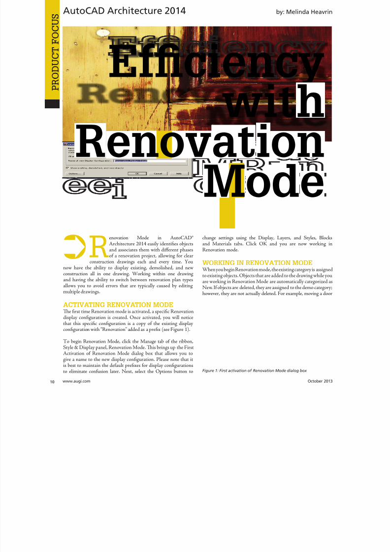
8122019 augi world 2013 10
httpslidepdfcomreaderfullaugi-world-2013-10 1052wwwaugicom October 20
AutoCAD Architecture 2014
PRO
DUCT
FOCUS
by Melinda Heavr
Renovation Mode in AutoCADregArchitecture 2014 easily identifies objectsand associates them with different phasesof a renovation project allowing for clear
construction drawings each and every time Younow have the ability to display existing demolished and newconstruction all in one drawing Working within one drawingand having the ability to switch between renovation plan typesallows you to avoid errors that are typically caused by editingmultiple drawings
ACTIVATING RENOVATION MODETe first time Renovation mode is activated a specific Renovationdisplay configuration is created Once activated you will noticethat this specific configuration is a copy of the existing displayconfiguration with ldquoRenovationrdquo added as a prefix (see Figure 1)
o begin Renovation Mode click the Manage tab of the ribbonStyle amp Display panel Renovation Mode Tis brings up the FirstActivation of Renovation Mode dialog box that allows you togive a name to the new display configuration Please note that itis best to maintain the default prefixes for display configurationsto eliminate confusion later Next select the Options button to
change settings using the Display Layers and Styles Blocand Materials tabs Click OK and you are now working Renovation mode
WORKING IN RENOVATION MODEWhen you begin Renovation mode the existing category is assignto existing objects Objects that are added to the drawing while yoare working in Renovation Mode are automatically categorized New If objects are deleted they are assigned to the demo categorhowever they are not actually deleted For example moving a do
Efficiencywith
RenovationMode
Figure 1 First activation of Renovation Mode dialog box
8122019 augi world 2013 10
httpslidepdfcomreaderfullaugi-world-2013-10 1152October 2013 wwwaugiworldcom
AutoCAD Architecture 2014
will create a new door as well as a demo door alongwith the corresponding wall openings It is importantto note that existing and new walls will automaticallyclean up after each other while in Renovation Modehowever demolition and new objects do not interactTis will be discussed more later in the article
In the display configuration for Renovation objectsare displayed according to their display representationWithin this display configuration Existing Newand Demolished categories are specified Tey can beviewed in plan elevation and section displays Both 2Dand 3D objects will display according to the categoriesthey are assigned in plan elevation and section viewsDimensions are important to mention here aswell When you use AEC dimensions you cannotautomatically ignore objects by Renovation categoryAll existing demolished and new objects aredimensioned Any undesirable dimensions must bemanually removed
Objects can be manually assigned to a Renovationcategory if needed Te display properties will changeaccording to the category specified Tis option maybe necessary for 2D multi-view block or block objectsbecause these objects are automatically assigned tothe Existing category when you begin a Renovationsession o do this click the Assign Existing AssignNew or Assign Demo buttons according to yourneeds Next select the objects to be assigned to thespecified category and hit Enter
o make things easier you can click the Select
Existing Select New or Select Demo buttons on theRenovation panel of the ribbon if you have severalitems to work with at once Once selected you cancomplete a command such as Delete
RENOVATION MODE SETTINGS
FOR OBJECTSDesign rules for New Demolished and Existingcategories by object type are controlled by Renovationstyles You can import Renovation Styles fromexternal catalogs or export to external catalogs inthe Renovation Options dialog box For maximumflexibility Renovation styles for display and layerassignment can be specified independently from eachother and are saved to the current drawing
In the Renovation options dialog box the Display taballows you to specify the Renovation Display Style aswell as to set specific design rules for objects such aswalls and doors (see Figure 2) Te layer tab allowsyou to set the Layer Assignment Style and to specifya prefix or suffix to layers in lieu of changing the layername (see Figure 3) Te Styles Blocks and Materialstab allows you to add a prefix or suffix to styleblock
Figure 2 Display options
Figure 3 Layer options
8122019 augi world 2013 10
httpslidepdfcomreaderfullaugi-world-2013-10 1252wwwaugicom October 20
AutoCAD Architecture 2014
PRO
DUCT
FOCUS
names to avoid naming conflicts between objects in differentRenovation categories (see Figure 4) Tis is much quicker thanhaving to manually rename each object When the DuplicateMaterial Definitions box is checked a copy of the material isautomatically generated and assigned to the building object Tecorresponding color settings will automatically display
ENDING A SESSION IN RENOVATION
MODEOnce you are finished working in Renovation Mode endingthe session is simple On the Renovation panel click the CloseRenovation Mode tool It is important to note that if changesare made to the drawing after Renovation Mode has ended theuncategorized objects are automatically assigned to the Existingcategory when you reactivate Renovation mode
MODIFYING THE RENOVATION DISPLAYYou can change how properties of objects within specific categoriesare displayed in the drawing by unlocking them changing themindividually per object type and saving them as the Renovationdisplay style Modifications made are saved to the current drawingTe lock icon to the left of the property signals whether thisproperty can be changed If the property is unlocked any changesmade to the display are reflected in the drawing
With the Renovation drawing open in an active Renovation modeclick Options on the Renovation panel Te Renovation Optionsdialog box displays On the Display tab select the display style toapply to the current drawing and enter a description Renovation
styles can be modified and saved deleted and imported fromexported to an external catalog Now select the object type fthe design rules and then select the checkbox to the left of eaproperty value for the category you want to change Modify tproperties as desired and select Prompt for objects to updatSelect the objects to modify or press Enter to select all objec
Changes to the selected properties for the specified objetype are applied in the current drawing
CONTINUING TO WORK IN
RENOVATION MODEWhen Renovation Mode is reactivated in your drawing texisting Renovation display configuration can still be used you can create a new one Te objects that were previouscategorized in an earlier Renovation phase will retain therepresentation and category Any objects that do not yhave a Renovation category will be automatically categorizand displayed as Existing objects Te ldquoShow existing neand demolished objectsrdquo option is automatically selected default It is recommended that this option remain selecteas it ensures that categorized objects in your Renovatioplan remain visible while switching between the DemolitioRenovation and Revision displays
o continue working in Renovation Mode select the Manatab on the ribbon then click the Style amp Display panand finally click Renovation Mode Tis will display tRepeated Activation of Renovation Mode dialog box (sFigure 5) Next you will need to specify the settings in tdialog depending on what you want to do o begin with existing Renovation display configuration click the drodown arrow next to Activate an Existing Renovation Displ
Configuration select the display you wish to use and cliOK o begin with a new display configuration select t
Create a New Renovation Display Configuration Named buttoenter a name for the new configuration and click OK Next yocan change the display style or design rules of objects by clickinthe Options button at the bottom left of the dialog box Click Owhen finished Ten click OK again to exit the dialog box You anow working in Renovation Mode again
Figure 4 Styles Blocks and Materials options
Figure 5 Repeated activation of Renovation Mode
8122019 augi world 2013 10
httpslidepdfcomreaderfullaugi-world-2013-10 1352
AUGI Members Prepare for the Future of Design
Join industry experts and design visionaries for 3 intensive days of classes andconversations on this yearrsquos hottest topics ndash 3D Printing BIM Cloud ServicesPLM Reality Capture and more
AUGI Highlights at AU 2013
bull AUGI Day Join the scavenger hunt and win great prices
bull AUGI Annual meeting and Beer Bust Get informed on AUGIprograms and planshellipand end the day with a cold brew
bull AUGI Top DAUG Contest Show your cerebral prowess the grandprize winner receives a free AU 2014 pass and HP notebook
bull Come visit the Community Pavilion on the Exhibit Floor to meetyour fellow professionals from the International Communities
Register starting September 12 2013 at httpauautodeskcom
Autodesk University 2013December 3-5 2013The Venetian Hotel Las Vegas
8122019 augi world 2013 10
httpslidepdfcomreaderfullaugi-world-2013-10 1452wwwaugicom October 20
PRO
DUCT
FOCUSAutoCAD Architecture 2013
ACTIVATING A DEMOLITION PLANTe display of a demolition plan shows existing construction andthose objects categorized as demolished All new objects howeverare hidden Display settings for the demolition plan type arelocated in the options dialog box for Renovation Mode
o create a demolition plan activate Renovation Mode as
previously discussed and then select the button for DemolitionPlan on the Renovation panel of the ribbon You can now selecta Renovation Display Configuration to activate Te box next toHide All New Objects is automatically checked If you want Newobjects to show while you are working in the drawing click in thebox to deselect the item and then click OK You can also click theNew ShowHide button on the Renovation panel You are nowready to begin creating a demolition plan
Please note that yellow is automatically assigned by default todemolition objects Tis can be changed in the options dialog boxfor Renovation mode under the Layer tab
ACTIVATING A REVISION PLANA revision plan displays new and existing construction objects butall demolition objects are hidden automatically Display settingsfor the revision plan type are located in the options dialog box forRenovation mode
o create a renovation plan activate Renovation Mode as previouslydiscussed and then select the button for Revision Plan on theRenovation panel of the ribbon You can now select a Revision
Plan Display configuration to activate Te box next to HiAll Demolished Objects is automatically checked If you waDemolition objects to show while you are working in the drawinclick the box next to deselect the item and then click OK You caalso click the Demo ShowHide button on the Renovation panYou are now ready to begin creating a revision plan
MANUAL MODIFICATIONSSometimes walls of different renovation categories do not intersecorrectly so manual modifications become necessary Tis can bdone by temporarily suspending Renovation mode For exampyou may have a plan that includes walls categorized as demolitioand walls categorized as existing with wall edges that need to corrected Remember objects categorized as New do not interawith objects categorized as Demolition When you need to maka manual correction you temporarily interrupt Renovation moby freezing the walls you want to modify and then correcting thedges Tese changes are not considered part of Renovation Toption to freeze or thaw walls is only available when Renovatiomode is active
Letrsquos make this a little clearer o do a manual modification clicthe Freeze Walls button on the Renovation panel of the ribboNext select the walls in question and hit Enter Renovation mois now temporarily suspended Proceed with correcting the wedges and then click Taw Walls when finished Renovatiomode resumes
RENOVATION STYLES CATALOGTe Renovation styles catalog contains display and layassignment styles AutoCAD Architecture-based styles for objecare managed with Style Manager By default the Renovation styl
catalog is installed in ProgramDataAutodeskACA ltversiongtenuStyles If the Renovation styles catalog is renamed or movethe styles are disabled and cannot be accessed Use the RenovatiStyles Catalog Settings dialog box to specify a valid catalog
With the Renovation drawing open in an active Renovation modclick Styles Catalog from the Options drop-down menu on tRenovation panel Te Renovation Styles Catalog Settings dialbox displays Select the Import renovation styles from catalcheckbox for drawings to be populated with all Renovation stylin the specified catalog Clear the Import renovation styles frocatalog checkbox for new drawings to include standard styles onlBrowse to the location of the Renovation styles catalog you wa
to use Click OK
Melinda Heavrin is a CAD Co-ordinator amp Facility Planner forNorton Healthcare in LouisvilleKentucky She has been usingAutoCAD Architecture since re-lease 2000 Melinda can be reached
for comments and questions atmelindaheavrinnortonhealthcareorg
Figure 6 Demolition dialog box
Figure 7 Revision dialog box
8122019 augi world 2013 10
httpslidepdfcomreaderfullaugi-world-2013-10 1552October 2013 wwwaugiworldcom
Inventor 2014by Mark Flayler
F
ree Autodesk Inventorreg apps You meanlike a Bloominrsquo Onion at Outback Countme in Wait you mean Inventor apps asin applications that change how Inventor
works for me and makes me more productive OkayIrsquom still in but I also still want some fried food
In this article we will take a look at severalof the free apps available in the AutodeskInventor Exchange store for trial purchase andSubscription customer benefits
DESIGN CHECKERTe first one we will take a look at is the DesignChecker that was previously called Validus and
sold through DMSI Autodesk purchased thissoftware in a manner similar to its purchaseof the iLogic code from Logimetrix a coupleyears ago Luckily I was a user back before thisacquisition so I know the tool pretty well Tefact that the software went from costing around$3000 to being a free tool delivered exclusivelyto Subscription customers is a really nice benefitfor having an Autodesk subscription right now
Te Inventor Design Checker is a productivitysolution that gives the designer insight into the
adherence of company or customer standards for
the product being designed Live Checking gives instant feedbackto the user and ensures a high level of quality for the entiredesign process
Users can use pre-defined checks or define custom checks withiLogic scripts to perform design checking Executing the on-
10 AppExchange
Reviews
Figure 1
8122019 augi world 2013 10
httpslidepdfcomreaderfullaugi-world-2013-10 1652wwwaugicom October 20
Inventor 2014
PRO
DUCT
FOCUS
demand checking updates the design checker results and enablingthe live-checking allows users to get the real-time feedback fromthe design checker during design process Te Design CheckerResults ree Browser allows users to interactively edit the objectswith failed checks and a Design Checker Results Report shows allthe passed and failed check results and allows users to export thereport to Excel Word or pdf or print the report
Now what I really enjoy about this tool is the iProperty checks andsome of the modeling checks Te machining checks I could livewithout mostly due to the fact that most companies try not to hireusers who make such drastic mistakes in machining operationsMy favorite thus far is the unconstrained sketches check thatvalidates my design before adding it to Vault I have also usedthis as a measuring stick before hiring new engineers or bringingvendor Inventor models into my design
AUTODESK REMOTETis next app allows some really nice RDP usefor Autodesk Inventor Autodesk Remote is astandalone application for Microsoft Window7 and 8 and is compatible with all Autodeskproducts It lets you drive Autodesk softwareinstalled on your primary computer from aremote computer or iPad for fast access to nativedesign data over standard networks o use itsimply install Autodesk Remote on the PC you
want to share Install it again on the machine youwant to connect from and start your connectionNote Autodesk Remote currently works only inNorth America
Autodesk Remote also has a companion applicationfor the iPad that allows you to access your hostPC from an iPad Te iPad app is optimized forAutodesk Inventor so you can work from anywhereimproving collaboration and increasing flexibilityDownlaod the iPad app from the Apple Store
Te controls in the iPad app are pretty easy to understand bthat doesnrsquot make a high-end CAD product made for the Pinstantly translatable to a touch interface You can see wheinterface elements of Inventor have started to lean more towarthis inevitable progression though
From my usage of the iPad app on my iPad 3 I found the usagelittle sluggish and gesturing a bit picky I found the use the ES
Figure 2
Figure 3
Figure 4
Figure 5
8122019 augi world 2013 10
httpslidepdfcomreaderfullaugi-world-2013-10 1752October 2013 wwwaugiworldcom
Inventor 2014
key a mandatory function as I often initiated one navigation tooland found myself trying to start something else before finishing thetool I was in In the end I see some fantastic usage on the horizonfor this app but right now it is pretty gimmicky for my taste I dopicture myself at some point on my front porch with my tabletinstead of my computer I would look cooler to the neighborhoodkids too
Be aware you will probably have to troubleshoot the setup of thisapp a bit I had to lock and unlock my computer and restart theapp several times before I got it just right
FEATURE RECOGNITIONTe Feature Recognition application converts neutral 3D CAD
models such as SEP SA or IGES solids into full-featuredAutodesk Inventor models Feature mapping could be executedautomatically or interactively as needed to maintain design intentCurrently there is one Automatic Feature Recognition commandand eight feature recognition commands you can use
Automatic Feature Recognition attempts to recognize specificfeature types and populate the browser tree with the recognizedfeatures A dialog box displays the feature types you can recognizein the Features section with the defaults checked You can selectfeatures you want to recognize and deselect features you do notwant to recognize
When you import a file it will offer to start feature recognition Ifyou decide to do it later you will have to find your Base1 solid inyour tree and right click on it to start it again
Tis tool has been around for a long time previously only on
Autodesk Labs Personally I donrsquot like it mainly because I have toconstrain and dimension the sketches when they get recognized bythe tool If your goal is to bring in a solid and then do some minormodifications to it then you are better off using the Edit Solidtools also shown in the image above If you want Work Plane toolsalso remember to turn off the Import into Repair Environment aswell before opening the file
If you really had to go the distance and recognize features it isactually a lot quicker and generally creates a more intelligentmodeling history if you just redo it yourself in Inventor Terecognition tools only lend themselves to simple parts inmost cases
Figure 6
Figure 7
Figure 8
Figure 9
8122019 augi world 2013 10
httpslidepdfcomreaderfullaugi-world-2013-10 1852wwwaugicom October 20
Inventor 2014
PRO
DUCT
FOCUS
WORK FEATURE VISIBILITYTis product allows Inventor users to manage all work featurevisibility in a fast and easy way keeping full awareness of the involvedentities Tis app consists of six buttons on part environment andanother six on assembly environment Inside of part environmenta user can choose to enable or disable the visibility property ofplanes axes or points Inside of assembly environment a user can
also choose on which components to enable or disable the visibilityproperty of planes axes or points
I had a little trouble with this app in the assembly environmentbut that was due to some bad installation files Tis is one appreally worth the $099 How often have you been in an assemblyand not wanted to go back to the part files to turn on and offwork features I recommend ungrouping them so you access bothcommands faster
SHEET METAL FLAT EXPORTTere seems to be a plethora of these apps on the Exchange witheach of them varying in price and options In general the ideabehind these apps is to help automate the process of getting a DXF
to a machine that reads them for manufacturing in a more efficientmanner Tese programs will scan an assembly file and find thesheet metal files on which to perform their routines
Te different variations of this program range from free trialsupwards of $100 for the paid apps I started with one that gave me
a ldquoliterdquo version that would do 20 sheet metal files and I liked it much I started using the full version
FEATURE MIGRATORTe Feature Migrator tool allows Inventor users to more eascreate part features from assembly features User can migraassembly features either by selecting them in the Feature Migratbrowser or by right-clicking on one or several of them and theusing the ldquoSend to Partsrdquo commands Features can also be directmigrated from the regular Inventor model browser using thcontext menu item added by the add-in
Once the operation of migrating features is completed the FeatuMigrator displays a dialog that provides information about thresults Tis first dialog is a ldquohigh-levelrdquo report of the migrationprovides the opportunity for the user to select the action to takfor all the assembly features migrated Suppress if SucceedeSuppress always Delete if Succeeded Delete always or Nothingalso for the part features that havenrsquot been migrated correctSuppress Delete or Nothing Features created by the add-in cbe in an invalid state in the parts for a number of reasons
Te user can also see when a feature is out of date from thassembly and perform updates from the part side
Figure 10
Figure 11
Figure 12
8122019 augi world 2013 10
httpslidepdfcomreaderfullaugi-world-2013-10 1952
8122019 augi world 2013 10
httpslidepdfcomreaderfullaugi-world-2013-10 2052wwwaugicom October 20
Inventor 2014
PRO
DUCT
FOCUS
TIME STAMPime Stamp is an Autodesk Inventor add-in that provides bull A low-cost simple-to-use tool that adds plot time information
to your printsbull A plot stamp that does not dirty the Inventor drawing
documentbull
A simple dockable user interface that keeps out of the way
Te ime Stamp editor lets you size position and orient thestamp relative to the adjacent sheet edges You can include datetime and current user information in the stamp Te time stamponly appears on the plot it does not alter the Inventor drawing
What I really like about this app even though it costs $500 perlicense is that you can find the price yourself and buy it It doeseverything it says it does and it provides an easy-to-use interfacewith an icon that changes based on whether the tool is on or offIf you want even more control over your plot stamping there is amore professional version offered by this company on their websitefor about $4000 a license which will allow more reporting fieldsand more control on the look and location of the stamp
SIMPLE SHEET SETTINGSSimple Sheet Settings combines the existing sheet settings withsome new tools such as changing the title block and also the abilityto make changes to all sheets in a document at once
Instead of first deleting the existing title block from a sheetexpanding the title block folder and inserting the desired titleblock then opening another window to change the sheet size andorientation just click the ldquoSettingsrdquo button located on the Sheetspanel in the Placed Views tab (right next to ldquoNew Sheetrdquo) andhave access to all those options in one location
When the Simple Sheet Settings window is loaded it gathers all the existing title block names and puts them into one drop-dowmenu o change the title block on the current sheet simply selethe desired title block from the drop-down menu and click OKTere is also the ability to change the title block sheet size ansheet orientation to all sheets at one time
Tis is a great little app that saves clicks and only costs a dollaQuite useful and no real setup involved
INTERACTIVE TUTORIALTe Create an Interactive utorial app provides instructions fcreating your own interactive Inventor tutorial Te Guide alincludes how to customize the Welcome Screen to display yointeractive tutorial and add to the ribbon
Tis one definitely falls under the ldquotoo much time on your handuser or CAD admin After reading through the guide on how create the interactive tutorials you find yourself asking the questioldquoWhy donrsquot I just save videos of the process we use in a companserver locationrdquo And that is when you uninstall this app as yohave realized that while it sounded good to you at first there abetter ways to accomplish the goal of company-specific tutoria
and process documentation
Figure 16
Figure 17
8122019 augi world 2013 10
httpslidepdfcomreaderfullaugi-world-2013-10 2152October 2013 wwwaugiworldcom
Inventor 2014
Te tools actually rely on too much externally controlled softwaresuch as Camtasia and other plug-ins and third-party apps to makeit work correctly Save your time and just use Camtasia from
echsmith to do your bidding
KEEPING UP TO DATEWith all these apps it is easy to understand how a user could getbehind on the updates to so many tools With that in mind theExchange Manager found on the ools tab in Inventor will keeptrack of that for you and offer assistance not only in updating butalso uninstalling and specialized help for each app
As a reminder with regard to third-party apps if you startexperiencing undesired effects in Inventor start turning add-ins
off one by one until you isolate which one is giving you fits Properreporting back on the app to the developers makes everyonehappier when the issue gets resolved Tus far I havenrsquot had nearas many issues as I thought I would have
ANY MANY MOREWith 80+ apps currently in the store and about 60 of them ready
for 2014 at the time of this article you should take some time andlook through what is available Tere are apps which are very nicheto the user base as well as those that have you scratching your headover why they are not already part of the core software Below aresome I would write about if I had more room in the article andora fatter PayPal walletbull BOM oolsbull EDM Expressbull Sketch Symbol Librarybull SolidWorks iProperty Importbull Quick Viewsbull 3D Pipebull Point Linkerbull Kwikools
Mark Flayler is an application engi-neer with IMAGINi echnologiesspecializing in manufacturing environ-ments He has implemented Autodeskmanufacturing products within severalindustries including the blowinjectionmolding automotive and custom ma-chinery markets When not providingtraining support and implementationhe writes the IMAGINi Manufac-turing Blog and takes an active role inthe manufacturing community Markis an AC certified instructor and isPSE and AC certified in AutoCADAutoCAD Mechanical AutoCADElectrical Autodesk Data Manage-ment and Autodesk Inventor
Figure 18
Figure 19
8122019 augi world 2013 10
httpslidepdfcomreaderfullaugi-world-2013-10 2252wwwaugicom October 20
SPECIALFEATUREAUGI Forums by Melanie Perr
The AUGI Forums are as always a busyplace Ask a question and you mightsee half a dozen varied methods andworkarounds posted in a single thread If
you have not had any questions yourself I would stilllike to encourage you to pop into the Forums and see
if there are any problems you could solve especially if you use one
of the less adopted products Tere will always be many helpinghands in the AutoCAD and Revit Forums but what about themechanical products or design visualization or structural detailingForums Peek in and see if you can share your experiences andwisdom with the community
I confess that I only scoured the English-speaking Forums forcontent for this article but please keep in mind that there areAUGI Forums available in 12 other languages so users have theoption of asking for support in their native tongue
AUTOCAD ndash SYSTEM VARIABLE
DISCUSSIONhttpbitly15M1hB9
Tis topic started out when a user couldnrsquot delete Te solution wasultimately the PICKFIRS variable but the discussion evolved tosafeguarding other variables automatically just to protect against aloss of settings in the event of a crash User Coloradomrg offeredthe safeguard shown in figure 1
Norton_cad also suggestsDIMLFAC EXPER andBLIPMODE be addedto the list
REVIT ndash
UNDERLAY
BEHAVIOR
EXPLAINEDhttpbitly15M1iFd
Mschroeder opened thediscussion with If you haveever wondered why some wallsdonrsquot show up in underlays or
show up inconsistently from floor to floor or why roofs and vieranges affect their behavior then read on
First rule of underlays Underlay view extent properties (cut rangdepth) are not user modifiable and not coupled to any othviewrsquos properties
Itrsquos also been mentioned ldquoIf objects are visible in the view ranof your current view AND in the view range of your Underlathey are automatically hidden in your underlay so there isnrsquotdouble instancerdquo
Users twiceroadsfool and dbaldacchino helped clarify the effecby posting sample models and pertinent data from the AutodeKnowledgebase and Autodesk Support Visibility View RangDetail Level and Cut Planes are all touched on in this discussioNeed clarity on how to make the most of Underlays Check inthis thread on the Forums
LISP ndash MAKING A DIALOG BOX RETAIN
ITS SELECTIONShttpbitly15JzMCc
Te LISP Forum always has such fascinating topics it is hato decide which to highlight From locking OSNAP options setting Explode options along with troubleshooting of existincode But the discussion surrounding the tutorials and metho
to retain selectioin a dialog box wvaried and lively so had to check it ou r e a v e s 0 4 4 1 3 2 1
even posted a sampdcl file when he wfinished
String Theory
8122019 augi world 2013 10
httpslidepdfcomreaderfullaugi-world-2013-10 2352October 2013 wwwaugiworldcom
AUGI Forums
AUTOCAD ELECTRICAL ndash LINES BEING
LABELED AS WIREShttpbitly1ew9p9D
Dinochrome says that one of his coworkers has reported aproblem with regular AutoCAD lines being labeled as wires
Crosswire35 advises ry checking your wire type edit dialogbox and make sure the ldquomake all lines valid wiresrdquo checkbox is unchecked
And IMCO goes on to say Using the vanilla line command inACADE will still place that line on a wire layer Change your linesto layer 0 and ACADE will not give them a wire number
AUTOCAD STRUCTURAL DETAILING ndash
TUTORIALShttpbitly17kW7cc
Te consensus is that this product is a little confusing to figure outand that most of the tutorials out there are older Most productshave a few videos floating around on Youube but this one doesnot seem to have too many yet
Jpo82 chimes in with I guess only tutorials forthis software are those found at Autodesk websiteTey are for versions 2010 and 2011 but still validhttpusaautodeskcomadskservlet12ampid=13111928 Irsquom not sure but sometimes I feel that the only new feature inASD 2013 is that itrsquos more stable than previous releases
Lucis29 goes on to say Also you might check some movieshttpwwwrobotofficecomasd but they are very old
Spenner then linked to his reporting of the Service Pack andissues it addressed hoping that it addressed some of the issuesthat came up in this discussion
NAVISWORKS ndash IMPROVE ANIMATION
EXPORT QUALITYhttpbitly1fQLoIv
Different methods are discussed from exporting individual imageframes to exporting a video (and how long) but I will leave youwith the following list from Revit For Breakfast
Here are the secrets to movies in Navisworks1 Donrsquot use materials ndash you make your render time much longer2 Use the PNG export option 15fps3 Make your video export twice as long as you need Ten speed it
up for a faux 30fps Tis is faster4 Look up the Navisworks blog by Lee Mullin and Paul Walker
about gooch and phong Tere is your faux render setting5 If you have NW 2012 you wonrsquot have gooch or phong but you
will have better export options 2013 has gooch and Phong butfewer export options
6 Te flickering occurs when multiple shapes overlap If you care
delete them in your export model Sometimes flickering occurs
in the generation of your frames on the PNG export You mayhave a frame that is ldquooffrdquo
7 Set your anti-aliasing to 4x or better on the png export8 Check out my old post httpforumsaugicomshowthread
php132209-Animation-Resolutionampp=1138298ampviewfull=1post1138298
CAD MANAGEMENT ndash NETWORK DRIVE
CHANGED BY IT WITHOUT WARNINGhttpbitly18J4k9c
Blackbox advises edinsmore595165 straight off to utilize theReference Manager program that comes with AutoCAD inorder to reconnect all of the external reference paths that werebroken when the I department upgraded their archaic serversHe further points out that moving from hard pathing to relativepathing would make things easier in the future
Feargt offers another twist Another option which would workon a need only basis when you open the specific drawing Change
XREF and Image paths in drawing to Network path throughscript on a need only basis Basically this will only change pathsPlace this line in a acaddoclsp file(command ldquoscriptrdquo ldquoyourserver and pathXREFREDIRECscrrdquo)and the following in a script fileREDIRB enter name of path to be replacedP enter new path
Tere was also a debate in this thread about obstacles and benefitsof user-managed and I-managed drive mapping
Melanie Perry is a Facilites-Manage-ment Coordinator and echnical Edi-tor in St Louis MO She is the AUGISalary Survey Manager and is curring-ly serving as an Officer on the Board ofDirectors Melanie can be reached atmistressofthedorknessgmailcomor found on witter asMistresDorkness
OTHER HOT TOPICSHave you found a Forum solution so mind-bogglinglyuseful that you leapt out of your chair with a whoopingcheer (or were at least tempted to) Please let me know Asingle person cannot read every post in our bustling AUGIForums so if you would like to see a thread highlighted ina future edition of String Teory feel free to let me knowSend me Wanderer a PM in the Forums or send an emailto MelaniePerryaugicom
See you on the Forums
8122019 augi world 2013 10
httpslidepdfcomreaderfullaugi-world-2013-10 2452wwwaugicom October 20
Revit Architecture 2014
PRO
DUCT
FOCUS
by Martijn de Rie
Myth Buster
Revit amp IFCPart 3
Irsquove given a lot of thought as to how this trilogyof articles should end At first I thought Irsquoduse the Coordination View 20 EXPRESS-GWallPaper for IFC2x3 (httpwwwmdr-
adviesnlwp-contentuploadsCoordinationView_V2-0_WallPaper_IFC2X3_Version-1pdf ) as a stepping stoneto give an ldquoIFC for Dummiesrdquo type of solution But that turnedout to be quite lengthy and rather boring But the link is includedabove for obvious reasonsmdashitrsquos useful
So I went back a little and asked myself ldquoWhy IFCrdquo And with thatquestion the inevitable follow-up immediately appeared ldquoWhynot IFCrdquo I realized that in the previous articles I failed to explainwhy in my humble opinion we should care about this somewhatcrooked badly implemented severe headache-inducing formatTerefore instead of explaining the fundamental technicalities ofIFC that can be explored in other places this final installment willexplore the Why versus Why Not IFC discussion and begin withthe latter
WHY NOT IFCWhen everybody uses Autodeskreg RevitregWell in this case itrsquos a no-brainer Share your Revit files Period
Loss of dataTis is an easier way to share data instead of hacking your wthrough IFC and praying your stuff doesnrsquot get lost in the proce
Even when you manage to export your geometry through IFtherersquos always loss of data
Loss of intelligence during importEven if you only need to send over geometry not data importithat into Revit makes it utterly useless All constraints are locomponent parametrics are gone and so on
Availability of bidirectional linksWhen not everyone uses Revit on a given project (which is quoften when yoursquore not located in the US) why not simply ua bidirectional linking between proprietary software standardTis can be easier and better to control
8122019 augi world 2013 10
httpslidepdfcomreaderfullaugi-world-2013-10 2552October 2013 wwwaugiworldcom
Revit Architecture 2014
WHY IFCWhich may be asked as why would you want to use IFC Or moreaccurately why would you want that option available
Consider what Sir Arthur Conan Doyle wrote ldquoOnce you eliminatethe impossible whatever remains no matter how improbablemust be the truthrdquo
Letrsquos put that to the test shall we
When everybody uses RevitOkay simple math Autodesk has around 7000 employees Teworld has about 72 billion people What are the chances someonenot working for Autodesk has a brilliant idea and creates thesoftware you need tomorrow Tere will always be better solutionsTey might not be viable for you overall but therersquos no reason toshut down access to them Revit is a wonderful generic tool forwhich I see a brilliant future with all kinds of additions for specificniche-markets like AutoCAD has
What about today DDS is MEP-engineering software that cando energy calculations (not simulations) inside your modelRhino lets you model things on the fly that could (arguably)take ages in Revitmdashif you ever get them done ekla lays wasteto the Revit structural rebar functionality any day of the weekwithout breaking a sweat Solibri is a wonderful solution for clashdetection and most importantly rule-based model checking andreportingmdashsomething Revit (or Navisworks) doesnrsquot do
Should I go on
Only problem for all this magnificent software Itrsquos either based onthe IFC format or requires model exchange through IFC
Te fact of the matter is there will always be better softwareAny one may be the software for you but that doesnrsquot mean yourpartners associates etc need to have the choice to use it forcedupon them
Loss of dataOn July 1 2013 there was an extra release for Autodesk softwareTe Sourceforge Open Source IFC Exporter released a new versionthat incorporated the option to map custom Revit parameters(shared or non-shared family or project even calculated values) totheir IFC counterparts
On September 28 2013 I had the honor of showing the secondstep in a complete and controllable data export from Revit
During my RC Europe class I showed the new option to create acustom IFC Property Set and map any given Revit parameter intoIFC fully customizable
IFC does not automatically lead to loss of data Tat idea is simplynot true Incomplete implementation in Revit does lead to loss ofdata As of now you are able to put any piece of data into an IFCeven calculated values And we didnrsquot change the IFC format We
just improved implementation in Revit
Loss of intelligence during importldquoJust because something hasnrsquot happened yet doesnrsquot meanitrsquos impossiblerdquo
I donrsquot know who originally had this insight and I doubt it to bethe movie line I remember but it is true
In the same RC Europe class I showed a native Revit familybeing exported to IFC altered and re-importedmdashwhile keepingall parametric constraints and even adjusting to the alterationsmade directly in the IFC file It is possible but not with thecurrent importer
Availability of bidirectional linksIrsquove been using Revit for almost 10 years now For 4-5 years I didnrsquotknow about IFC at all Before a year ago this was my strongestargument against IFC Why would you need a generic ldquolanguagerdquowith all its limitations (of which there are) weaker implementationand use of parametric capabilities (because it has) and lag-times indevelopment (by nature)
IFC will never be able to do what native software does simplybecause itrsquos responsive in nature Development budgets are afraction of what Autodesk rimble or Nemetschek get to spendon their software
So why not keep it simple and use a bidirectional link Revit has itwith a lot of other Autodesk software and third-party applications
But how long have we waited for them And are they even trulybidirectional Do they exactly do what you want them to do In myhumble opinion the answer to these questions is not very inspiringEven bidirectional links tend to have major limitations and severe
constraints in flexibility And most important Te link itself isalso propriety software No way of adjusting it to your needs
WHAT IF MORE PEOPLE STOPPED
TALKING ABOUT IT AND JUST GOT
INVOLVEDTe improbableFirst off itrsquos a matter of simple logic As Sir Arthur suggested ifwe can successfully check off all likely options to NO want touse IFC doesnrsquot that mean the improbable is true Tat IFC is infact a valuable tool in our toolkit and we should be able to use it
when necessary
Mind you Irsquom not saying you should use IFC If yoursquore on a Revit-only project it would be insane Just send and receive RVs Tefact is this will only be viable for limited parts of the buildinglifecycle If yoursquore lucky the entire design team is on Revit Butmanufacturers have other software facility managers too
As for the design team what if the best structural engineer is not[on Revit] or the MEP guy that has loads of experience in similarprojects Would you settle for second-best just because someoneuses the same brand of tools you do I wouldnrsquot
8122019 augi world 2013 10
httpslidepdfcomreaderfullaugi-world-2013-10 2652wwwaugicom October 20
PRO
DUCT
FOCUS
Revit Architecture 2013
Open AccessWhich brings us to the biggest advantage of IFC (or any open
format) itrsquos open Which means itrsquos adjustable to your needs Nowdonrsquot go ldquothatrsquos too difficult expensiverdquo Tatrsquos bullocks
Te first external enhancement to the Open Source Exporter wascreated by om Pesman a self-employed API specialist
Parametric IFCImplemented by Jon Mirtschin also self-employed IFCparametrics is available Agreed Jon is a well-known IFC guru butstill the point holds
Custom property sets and parametersWim as owner of a small MEP engineering firm hasadded functionalities toward this end and hersquos not even a trueAPI specialist
All these developments were done for free by altruistic volunteerefforts as part of the creation of the Dutch Revit Standards Andof course with the invaluable help of the Autodesk Open SourceIFC Exporter team Angel Velez in particular
But what if these guys actually got paid What if this projectwasnrsquot a Saturday night side-job What if more people stoppedtalking about it and just got involvedmdasheither by themselves or byleveraging experts to get what is needed Te entire IFC format is
Open Source the source code is out there which basically meansyou can do whatever you want and create whatever you needmdasheven on a project-by-project basis
BIM ITrsquoS THE ldquoIrdquo THAT MATTERSIn my humble opinion the entire debate on BIM is focusing on thewrong part of the acronym I donrsquot care if ldquoBuildingrdquo is a noun ora verb Nor do I care whether itrsquos ldquoModelrdquo or ldquoModelingrdquo nor am Icommenting on whether one should say ldquoBIM Modelrdquo
Itrsquos the ldquoIrdquo that matters If wersquore collaborating the Informationis most all I care about I just want your datamdashin the leanest
smartest and most effective way possible
A Revit model will do conversely a lot of times A Revit model w
give me heaps of data I donrsquot want geometry I donrsquot care about ana file format I canrsquot use Now we can all keep on being really anabout it or we can simply use the tools available to us one of thebeing IFC
A FINAL NOTEAs stated at the beginning of the article I really enjoyed writinthis series and for now this is the last of the series But if yoursquointerested in more tips and tricks on IFC let me know I might able to persuade the guys at AUGI to let me write about it againLord knows there is still a lot to talk about regarding IFC
Martijn de Riet is a self-employedBIM Consultant from the Nether-lands working with Revit since version51 Martijn has a bachelor degree inBuilding Science After his studieshe started his own engineering firmworking for contractors architects and
private clients Starting in 2007 hiscompany transformed into a full-timeBIM consultancy service At the mo-ment Martijnrsquos clients vary from mid-sized architectural firms to the largest
dutch General Contracter and MEPEngineering firms with a focus onspecific corporate solutions design andimplementations of Revit and BIMworkflows Martijn is a member ofthe Dutch Revit User Group and cur-rently working on creating a Masteremplate and Component LibraryHe provides lectures for companiestechnical universities seminars etc ona regular basis
Itrsquos the ldquoIrdquo that matters If wersquore collaborating the Information is most all I care about I justwant your datamdashin the leanest smartest and
most effective way possible
8122019 augi world 2013 10
httpslidepdfcomreaderfullaugi-world-2013-10 2752
wwwxicomputercom
8122019 augi world 2013 10
httpslidepdfcomreaderfullaugi-world-2013-10 2852wwwaugicom October 20
3ds Max 2014
PRO
DUCT
FOCUS
by Chris Murra
SUMMARY WHATrsquoS
CUSTOMIZABLE IN MAX
(HIGH LEVEL)When it comes to the customizability of Autodesk 3ds Maxregitrsquos no secret that it can morph itself into whatever you want theprogram to become
Whether yoursquore a modeler animator lighter rigger generalist ortechnical artist 3ds Max can become your own personalized toolbox that is an extension of your own hand in your daily workYou can now combine different command types (such as creatingobjects and object modifiers) into a single menu reducing themouse travel and improving efficiency
In this article wersquore going to take a closer look at one specificaspect of customization with 3ds Max the new enhanced UI Aspart of this article besides taking a deep dive into the operationof this feature I will also be showing how I created the ldquoMographrdquo
tools UI that includes custom buttons and icons At the end this article I will also provide a link to this UI so you can use customize it yourself or share it with others
ENHANCED UI SUMMARYWhat is the Enhanced UI
Te Enhanced UI is a new graphical user interface system thdoes two main things
1) It provides a refreshed 3ds Max user interface with updattool categories and new clusters of pre-existing tools in groupinthat are more akin to their intended purpose as opposed to somtechnical requirement for menu placement
2) It provides a way to allow you the end user to customize thmenu system in almost any way you choose Te drop-down menare ldquotear-ablerdquo (not to be confused with ldquoterriblerdquohellip but I digresand the resulting configurations are savable either by scene or
3ds MaxEssentialsCustomizing
the UI
8122019 augi world 2013 10
httpslidepdfcomreaderfullaugi-world-2013-10 2952October 2013 wwwaugiworldcom
3ds Max 2014
a preset Tey are also distributable and deployable so they can beshared with others
Where is the Enhanced UITe Enhanced UI can be found in the upper left hand corner of themain UI at the very top of the screen Tere is a drop-down menuthat says ldquoWorkspace Defaultrdquo Tis default is the same baselineUI that ships with all 3ds Max installs (Figure 1)
Within the drop-down you can find the ldquoDefault with EnhancedMenusrdquo Tis is the alternative default menu system that youcan use on its own or use as a starting point to create your owncustomized menus
BASIC DEFAULT CUSTOMIZATIONEnhanced UI Customization BasicsNow that wersquove enabled the Enhanced UI how can we change it
SOP Before you begin mucking around with the UI Itrsquos importantto understand what I call the ldquosave-logicrdquo as it pertains to custom UIs
Te UI Save LogicIf you plan on saving this UI for future use there is a specificmethod you must follow to properly save the UI you want and notwreck the default Enhanced UI
Te Save Logic is as follows Itrsquos simple but important
Step 1 urn on Enhanced Default UI (Figure 3)
Step 2 Click ldquoSave as New Workspacerdquo FIRS At this point youwill be prompted for a new name (Figure 4)
Step 3 Edit and change the UI at will
NOE All future edits are ldquoautomatically rememberedrdquo as you go (Iintentionally did not use the word ldquosaverdquo)
Step 4 Te ldquosave as default staterdquo button is important When wehave completed the customization process we then choose thisbutton to ldquolockrdquo in the changes Tis is different than Saving a UIwith a custom name
HO IP ldquoBut this methodology seems backwardrdquo
I can see how yoursquod say that but remember that any changes you make
to any enhanced UI are automatically ldquorememberedrdquo If you create acustom UI then while working you make some temporary changeswhen doing something specific those little changes are automaticallyremembered If you want to return to the default state [of yourcustomized UI] you select ldquoReset to default staterdquo Tis does NObring back the default Max UI rather it brings back the customizedUI you created in ldquolockedrdquo in Step 4
Okay now that you have the save logic down letrsquos begin customizing
1) If you havenrsquot done so already turn on the Default Enhanced UI
2) Go to ldquoManage workspacesrdquo from the drop-down and in the
Figure 1 Workspaces are in the Workspace drop-down menu
Figure 2 Default UI (left) and the Default Enhanced UI (right)
Figure 4 Saving the New UI Workspace
Figure 3 Turning on the Enhanced Default UI
8122019 augi world 2013 10
httpslidepdfcomreaderfullaugi-world-2013-10 3052wwwaugicom October 20
3ds Max 2014
PRO
DUCT
FOCUS
Manage workspaces dialog choose ldquoSave as new Workspacerdquo Giveit a specific name
3) Begin making your desired changes
Since a custom UI is specific to any one individual letrsquos take a lookat what types of customizations can be made
Simple ChangesOne of the simplest things to do is peel off any commandgroup (see Figure 5) Just click the group title bar and drag Tecommand group becomes a floating dialog box Now just becauseyoursquove peeled it off does not mean that yoursquove removed it fromthe drop-down menu Te ldquooriginalrdquo command group remains inthe drop-down You can just close the floating dialog when yoursquoredone with it
Probably the simplest thing you can do is reorganize the menusIn each drop-down menu appears a group of commands You maynotice that some command groups are icons and some are words(Figure 6) o change the appearance of the commands there is asmall icon in the upper right corner of each group of commands(Figure 7)
Te next change is alreally simple Is tcommand group op(expanded) or clos(rolled up) Just clion the plus or minsign in the upper le
corner to set this stafor the next time yolaunch 3ds Max (Figu8) Remember thesettings are saved as yogo so whether it is opor closed is your choicbut the state the menis in when you cloMax is the one that remembered the netime Max opens
What about Saving tDefault state More othis later
Once you have floating menu yocan combine differecommand groups dragging any othcommand group to aother floating dial
that yoursquove created Tis makes for easy creation of custom dialo
based on specific tasks Figure 9 shows a command group fcharacter animationFigure 5 A floating menu that has been torn off the drop-downmenu
Figure 6 The different display states of the menus
Figure 7 Changing menu layouts
Figure 8 Rollouts
8122019 augi world 2013 10
httpslidepdfcomreaderfullaugi-world-2013-10 3152October 2013 wwwaugiworldcom
3ds Max 2014
ADVANCED CUSTOMIZATION
What about completely custom interfaces Herersquos how we do thatwith the Enhanced UI menu system
Te following is the high-level overview of the process Wersquoll thenunpack each step in more detail
If you havenrsquot read the section on Basic default customizationplease do so before continuing Before starting this phase ofcreating your new UI you should have saved your new UI stateTat process is explained in the previous section
1) Create a main drop-down menu (like ldquoMy oolsrdquo)
2) Create a tools category menu into which you will place yourtools (a submenu such as ldquoModeling oolsrdquo or ldquoAnimation oolsrdquo)Drop-downs can have more than one subcategory
3) Add commands to various submenus
4) Clean up the UI by creating custom names adding separatorsor creating custom icons
First letrsquos create a new menu for the menu bar Tis is done easilyfrom the CustomizegtCustomize [Rollout]gtCustomize UserInterface dialog box
Steps for Creating a Drop-Down Menu1) Create a New Menu and give it a name (see Figure 10)
2) Locate your new menu in the Menus window It will be listedalphabetically (Figure 11)
Figure 9 Multiple command groups in one menu
Figure 10 ndash Creating a new drop down menu
Figure 11 Location of new menu
8122019 augi world 2013 10
httpslidepdfcomreaderfullaugi-world-2013-10 3252wwwaugicom October 20
3ds Max 2014
PRO
DUCT
FOCUS
3) Drag your newly created menu category over to the column onthe right Tis will add your new drop-down menu to the interfaceimmediately and you can begin populating it with menu items (seeFigure 12)
UI DESIGN IP Te actual menu name and display name can bedifferent I used a custom menu name behind the scenes so I couldeasily differentiate my menus from the ones created by default or other
tool companies After you create a menu and add it to the right column you can right-click on it and change its display name (see Figure 13)
Next letrsquos create a command group1) Just like in Step 1 from the previous section create a new men
2) Tis time before you drag it to the right column click thplus sign next to your drop-down menu item to expand it Tedrag the new item to the right column dropping it ldquounderrdquo thmenu name
3) Drag any commands from the Commands window on the leto the submenu on the right (see Figure 15)
Herersquos an example from my Mograph ools workspace thshows how a completed menu looks once it is created (Figu16) In the following figure you see both the menu as it appeain the Customize UI dialog and the actual menu (which has bepeeled off)
Notice that some of the commands on the menu are greyed ouTatrsquos because this new menu combines both ldquoObject creatcommands and ldquoObject Modify Commandsrdquo in one menTey will remain grey until you create an object on which thwill be used
Figure 12 Adding the new menu to the UI
Figure 14 Creating a command group
Figure 15 Dragging commands onto the menu
Figure 13 Custom menu names
8122019 augi world 2013 10
httpslidepdfcomreaderfullaugi-world-2013-10 3352October 2013 wwwaugiworldcom
3ds Max 2014
Adding SeparatorsSeparating commands is easy and is recommended to help you oryour intended user make sense of the how the tools are arranged inthe menu Creating a separator is as easy as dragging one over theright column just like a menu or command
HO IP ldquoWhy do I need to create another menu Why canrsquot I addtools right to my menurdquo
Te main reason is that adding a submenu gives you the ability to tearoff the submenu If it werenrsquot in a submenu it wouldnrsquot be tear-ableSo itrsquos really a ldquobest practicesrdquo kind of thing But even if you try to notadd the submenu it will happen automatically Itrsquos important to do it
explicitly so you are aware of what submenus are in the menu and that you are the one in control of what command is going where
CUSTOM ICONSNo custom UI is complete without a custom set of iconsAdditionally not all commands in 3ds Max have their own iconyet But itrsquos important to realize that regardless of how you set up
your UI yoursquore still working within the framework of an existingapplication and there are boundaries to what you can edit andcreate Icons have specific requirements both in their creation(size) location and file name that must be adhered to in order forthem to work properly
SizeformatTe size of icon is pretty simple It must be 32x32 pixels andPNG format
LocationTe location is very specific New icons must be added to thislocation
CProgram FilesAutodesk3ds Max 2014UI_lnResourcesDarkIconsMain
Te new icons I created for the Mograph UI are shown inFigure 17)
Icon File NameIf yoursquore still with me at this point we are now getting into thenether regions of customizing a UI Tis is where things get a littletricky but itrsquos really not too bad File names are specific and aregenerated by the application (3ds Max)
So letrsquos begin First identify the command for which you want aniconmdashusually itrsquos one that doesnrsquot already have an icon But if itdoes and yoursquore changing it MAKE A BACK UP of the originalicon PNG file Tis is because as previously stated you donrsquot havecontrol over the file name Tat means if yoursquore creating your ownicon you need to overwrite the existing one and use its name foryour new icon So back up any original icons
Figure 16 The completed menu
Figure 17 ndash The created icons
8122019 augi world 2013 10
httpslidepdfcomreaderfullaugi-world-2013-10 3452wwwaugicom October 20
3ds Max 2014
PRO
DUCT
FOCUS
It really doesnrsquot matter whether you make the icon first or not ofind the name you need to use you need to navigate as follows
NOE Yoursquore about to edit the ribbon Tere is no need to save thesechanges as we are merely extracting information from it But if yoursquoredoing a lot of custom icon work you may want to save this change to theribbon so you can come back and continue your work in later sessionswithout have to recreate this every time just to get the proper file nameSaving this ribbon is not related to saving your default state of yourUI When yoursquore done creating all your UI icons you can just delete
whatever changes you make to the ribbon
1) Open the ldquoCustomize Ribbonrdquo dialog box
2) Create a new ldquotabrdquo by dragging it onto the ldquoExisting Ucolumn in the middle (see Figure 18)
3) Using the same drag method add a new ldquopanelrdquo to ttemp tab (Figure 19)
4) Now you can get the information you need Find tcommand for which you are creating an icon and dragto the panel
5) Locate the ldquoinfordquo portion of the ldquoPreview Windocolumn At the bottom of the column is the file namneeded to have the icon used properly by the applicati(Figure 20)
CONCLUSIONSo now you know how to create a custom UI scheme f3ds Max 2014 and up By using the Enhanced UI me
system itrsquos really easy to generate a multitude of workspathat allow Max to work the way you want to work
Te example used in this article was the ldquoMographrdquo UI thI created for NAB 2013 If you would like to downloand install it you can get it from my ldquoPinning the Stacblog on the Area herehttpareaautodeskcomblogschrismurray
Enjoy
Chris Murray works for Autodesk
Media amp Entertainment He istrained as an animator (3D variety)but considers himself a creative tech-nologist His daily role is a technicalldquoevangelistrdquo for Autodesk creating marketing deliverables for 3ds Max Heis the author of Mastering 3D StudioMax He has a Masters in Fine Arts(MFA) in Computer Animation fromMiami International University of Artand Design Follow him on witterchrismmurray
Figure 18 Creating a tab on the ribbon
Figure 19 Adding a panel to the tab
Figure 20 Finding the required file name
8122019 augi world 2013 10
httpslidepdfcomreaderfullaugi-world-2013-10 3552
AUGIMembersReach Higherwith ExpandedBenefitsAUGI is introducing three new Membership levelsthat will bring you more benefits than ever beforeEach level will bring you more content and expertiseto share with fellow members plus provide anexpanded more interactive website publicationaccess and much more
MEMBERMEMBER MEMBER
Basic members haveaccess tobull Forums
bullHotNews (last 12 months)
bull AUGIWorld (last 12 months)
DUES Free
Premier members haveaccess tobull Forums
bullHotNews (last 24 months)
bull AUGIWorld (last 24 months)
DUES $25
Professional members haveaccess tobull Forums
bullHotNews (full access)
bull AUGIWorld (full access and in print)
bull ADN 2013 Standard Membership Offer
DUES $100
Are you ready to upgrade yourself and your membership
Access additional benefits and upgrade at wwwaugicom
8122019 augi world 2013 10
httpslidepdfcomreaderfullaugi-world-2013-10 3652wwwaugicom October 20
AutoCAD MEP 2013
PRO
DUCT
FOCUS
by Vladimir Triantafillid
BIM IsWhatrsquos
Driving theIndustry
For the past decade many would arguethat building information modeling(BIM) has metastasized aggressivelythroughout the AEC industry but what
does BIM really mean More importantly whatdoes it do for us and for our industry Ask someone who hasbeen in this industry for more than 25 years or those nearingretirement and yoursquoll find that less than half see its value muchless care to make the effort with its implementation hesequestions mean something different for those who have beenin the industry the past 10-15 years Recent college graduates
however with their tech-savvy capacity and high expectationare eager to implement anything that resembles cutting-edgflashy technology ypical ly they are the ones most receptivenot adamant about putting their talents to use through BIM
I recently gave a BIM presentation with an emphasis on mchanical systems to the summer interns and new hires our companymdashall were non-BIM users except for onemdashbmy presentation did little justice to BIM Half of my audence had found a cure for their insomnia when they realizthis wasnrsquot the latest edition of ldquoCall of Dutyrdquo hat was n
8122019 augi world 2013 10
httpslidepdfcomreaderfullaugi-world-2013-10 3752October 2013 wwwaugiworldcom
AutoCAD MEP 2013
reflection on BIM by any measure Simply put I fell shortof connecting with a potentially captive audience eager toknow what really makes BIM intriguing or how it wouldgive them an edge in the industry I didnrsquot think to look pastpresenting the facts of its processes and benefits o simplyhave stated that proficiency in any of its many facets willpromote a lucrative career would give those still awake theimpetus to jump ship In hindsight the first step I shouldhave taken to begin this presentation was to ask what theywanted to get out of BIM
If you think itrsquos hard conveying the value and splendor ofBIM to receptive and impressionable young minds try toconvince the weathered veterans dead-set in their ldquooldtricksrdquo For every experienced veteran who has converted toBIM there are two ldquoold dogsrdquo that canrsquot shake ldquothe good olrsquodays when we used vellum and light tablesrdquo Guess whatmdashanincreasing amount of naysayers are starting to come aroundincluding those who say theyrsquove been burned by BIM in thepast hey are seeing the simple solutions BIM presents and
how these solutions translate into cost savings More andmore of those who had formerly questioned BIMrsquos utility areconvinced when installation efficiencies are not only real-ized but quantified
Another factor in the evolution of BIM is its tendency toexpand faster than the pace of its general population of us-ers hose of us proud to be catching up to what we think iscutting edge quickly realize it was just another false sense ofaccomplishment as BIMrsquos web continues to grow exponen-tially he solution is rather simple Focus on what you canhandle and always have the presence of mind and sense ofcaution to avoid being overwhelmed by the wake of BIMrsquos
progress herersquos plenty of money to be made and countlessfacets to explore as long we have the following mentality Welive in the information age and those wi lling to share knowl-edge will reap the rewards of communal synergy
On the opposite end of the spectrum you might find ourindustryrsquos opportunists In a hurried frenzy to claim theirspot in the intellectual property queue these opportunistsget carried away with pioneering what they assume is the lat-est improvements to BIM Instead of stopping to absorb anddevelop the benefits of 4D 5D 6D and so on the pioneersare spreading these ldquoDsrdquo thin with abandon further expand-
ing the gap between quality and quantity None of this i s tosay that wersquore heading in the wrong direction On the con-trary letrsquos call it more of a positive economic problemmdashthedemand for BIM expertise and development outweighs thesupply of available users
Fortunately as collegiate curricula catch on to this industrytrend the point of equilibrium will soon follow For as longas I can remember respective companiesrsquo 2D CAD depart-ments have been a significant source as the breeding groundfor potential BIM users While this route hasnrsquot changedregarding the career path of a draftsperson the source poolhas expanded to include architects engineers and construc-
tion managers just to name a few Itrsquos even hard not to noticeits stark demand when BIM and Revit courses are being in-creasingly offered at local community colleges I knew thenthat you didnrsquot necessarily need an undergraduate degreeback when I got my foot in the door of this industry hisprobably wonrsquot hold true in the coming years Still the privi-leged few who are already a part of this industry subset canrely on their experience in this fast-paced market to con-tinue to propel their careers forward ever faster All thesefew need to do is grab onto a small piece of BIMrsquos wing andhang on tight for the ride he fresh-out-of-college e ntrantsmight have a harder time grabbing onto this wing thatrsquos al-ready in motion
o those who are only vaguely famili ar with BIM it is typi-cally perceived as the equivalent of a 3D role-playing videogame In this case itrsquos not difficult to capture a ldquosnapshotrdquoimage of a 3D model shadows cast across random metal ob-
jects taking up space in an orderly fashion between ceil ingspaces and walls What is difficult is conveying the abun-dance of value behind the pretty picture to a client whorsquosonly interested in the pretty picture Who isnrsquot familiar withthe adage ldquoa picture is worth a thousand wordsrdquo Why notchange that saying to ldquoa BIM model is worth five thousandhyperlinksrdquo Now wersquore talking lifec ycles and facilities man-
More and moreof those who had
formerly questioned
BIMrsquos utilityare convinced
when installationefficiencies are notonly realized but
quantified
8122019 augi world 2013 10
httpslidepdfcomreaderfullaugi-world-2013-10 3852wwwaugicom October 20
AutoCAD MEP 2013
PRO
DUCT
FOCUS
agement his supposed video game has suddenly becomean encyclopedia of usable information But wait itrsquos not juststatic information thatrsquos stuck on a DVD on a shelf i n someownerrsquos random storage closet It has now become a livingdynamic source of real-time data Maintenance technicianswill know exactly where to go when the active 3D modelloaded on their laptop highlights a hot water pump needingservice while concurrently bringing up the cut sheets andoperation and maintenance manuals specific to that pumpor system Better still the source of information has shiftedfrom multiple stacks of large drawing sets collecting dust toseveral hundred gigabytes on a hard drive Yes Mrs Clientyour 3D BIM model will be usable for the next 20+ years
Even though you might not necessarily think about i t someof you probably realize that BIM has become the ldquomiddle-manrdquo for so many key components in the construction cyclewell beyond its intermediary role between design and con-struction phases You want to do some significant tenantimprovement in an existing building Laser-scan the exist-ing conditions hatrsquos BIM Is the general contractor rackingtheir brain trying to f igure out where to station the crane forthe project or pave the pathways for delivery trucks Nowtheyrsquore looking to BIM to answer these questions and opti-mize their decisions o take it a step further at which endof the building do we want to load thousands and thousands
of pounds of sheet metal and pipe And then which tradesshould be installing their systems first in any given area ofthe building hatrsquos right wersquore deriving sequencing andtimelines from the BIM model to e stablish the best routes totake while addressing any constructability issues BIM hasbecome the consultant that wears most of the hats Itrsquos ourone-stop shop
I know that Irsquove personified BIM as if itrsquos the brains behindall of its success Letrsquos take a moment to focus instead on itscollaborators or the sum of its integral parts to show thatin reality we are Dr Frankenstein and BIM is our monster
Except in our ca se wersquore beginning to ta me our monster anthose who were previously frightened by it are starting to sthat it indeed is no monster In fact while evolving to domdashand becomemdashgreater things BIM is transforming into aindustry hero he point of convergence is approaching bcause wersquore saving money time and even trees Soon enougBIM will be the industry standard even on the smaller proects Letrsquos keep the pedal to the meta l
You want to know the best news Most of us havenrsquot evebegun to scratch the surface of BIM but wersquore in strategpositions to reap the rewards aking the possibility of ivast potential into account isnrsquot it reassuring knowing th
in these tough economic times wersquore engaged in an industthat has a shortage of well-qualified BIM experts Our eposure alone sets us up for success Now ask yourselves thquestion Is BIM driving our industry or is it the BIM use
Vladimir riantafillidis works for aleading mechanical contractor in theSan Francisco Bay Area with morethan 10 years of experience in the in-dustry Although he has a bachelorrsquosdegree in biology his unique careerchoices have firmly rooted him in a
substantial BIM role awarding himthe opportunity of progressing along-side the relentless evolution of BIMOutside of his career hersquos always opento new adventures whether trying anew cuisine exotic travels or extremesports Te latter adventures have re-cently subsided as the balance of lifehas shifted his focus on spending timewith his growing family
You want to know the best news Most of us havenrsquot
even begun to scratch the surface of BIM but wersquore
in strategic positions to reap the rewards
8122019 augi world 2013 10
httpslidepdfcomreaderfullaugi-world-2013-10 3952
8122019 augi world 2013 10
httpslidepdfcomreaderfullaugi-world-2013-10 4052wwwaugicom October 20
Revit Structure 2014
PRO
DUCT
FOCUS
Streamlining
Sheet Listswith a Custom
Application
In this article we take a brief look a simpleadd-in for Autodeskreg Revitreg named X-Sheetswhich provides tools for incorporating sheetsfrom an AutoCADreg sheet set in a Revit sheet
list ypically this is handled by manually addingplaceholder sheets to the Revit sheet list Tis can be problematicbecause the sheet list becomes disconnected from the sourceand must be updated manually With X-Sheets sheet set datais exported directly from AutoCAD linked to a Revit project
and included in the sheet list by automatically addingupdatinplaceholder sheets For this example all structural scheduleplans elevations and section sheets are in Revit Structure Adetail sheets will be pulled from an external AutoCAD sheet set
X-SHEETS RIBBON PANEL Te first command on our ribbon panel is Discipline Tcommand is used to establish the Revit project parameter twhich the AutoCAD sheet subsets will be mapped For th
by Jonathan Albe
Figure 1 Revit X-Sheets ribbon panel
8122019 augi world 2013 10
httpslidepdfcomreaderfullaugi-world-2013-10 4152October 2013 wwwaugiworldcom
Revit Structure 2014
example we have created a project parameter named My DisciplineParameter Each Revit Structural sheet has been assigned a valueof SRUCURALmdashthe same as the subset name for theAutoCAD detail sheets Te sheet list is grouped and sorted bythis parameter
Te next command on the ribbon panel is Links Tis command isused to establish a link between the Revit project and XML file(s)
containing sheet information exported from AutoCAD You cancreate as many links as needed and use relative paths if required
Te next two commands Sheets and Update do the work ofaddingupdating placeholder sheets to the sheet list While theSheets command allows you to select individual sheets from linksto include in the sheet list the Update command includes all sheetsfrom all links
EXPORT SHEETS FROM AUTOCADFigure 3 shows the AutoCAD X-Sheets ribbon panel and asample sheet set containing structural detail sheets Notice thedetail sheets are grouped under a subset named SRUCURALTis subset name can be exported with each sheet and mapped to
the My Discipline Parameter in Revit Figure 3 shows the ExportSheets dialog with an option to include subset information and theability to exclude individual sheets Selecting the Export buttonprompts us with a dialog to save an XML file to be linked into ourRevit project
Figure 2 Discipline command dialog
Figure 3 AutoCAD X-Sheets ribbon panel and sample sheet set
Figure 4 Export sheets dialog
Figure 5 Export complete
8122019 augi world 2013 10
httpslidepdfcomreaderfullaugi-world-2013-10 4252wwwaugicom October 20
Revit Structure 2014
PRO
DUCT
FOCUS
ESTABLISH LINK TO XML FILE IN REVIT
PROJECTFigure 6 shows the Manage Links dialog A link has been added tothe XML file we generated when exporting sheets from AutoCADNotice there is an option to make the link path relative to our
Revit Project location
IMPORT SHEETS FROM XML LINKFigure 7 shows the Revit Structure sheet list before any sheetshave been imported from AutoCAD After selecting the Sheetscommand we are prompted with a Manage Sheets dialog
For this example we have selected all sheets from the XML linto include in our sheet list After confirming the dialog neplaceholder sheets are immediately added to the sheet list angrouped according to the SubsetDiscipline mapping Te neplaceholder sheets are identified behind the scenes as being relatto the X-Sheets XML link for later updating
Figure 6 Manage Links dialog
Figure 9 Sheet list after import
Figure 7 Sheet list before import
Figure 8 Manage Sheets dialog
The X-Sheets
add-in is a great tool
for incorporating
AutoCAD sheets into
a Revit sheet list
8122019 augi world 2013 10
httpslidepdfcomreaderfullaugi-world-2013-10 4352October 2013 wwwaugiworldcom
Revit Structure 2014
UPDATE SHEETSFigure 10 shows the Export Sheets dialog in AutoCAD afterdetail sheets have been renumbered to include ldquo-Ardquo When changesare made to AutoCAD sheets the original export steps must befollowed to replace the XML file linked to our Revit project Oncethe XML has been replaced simply run the Update command inRevit to update the sheet list
SUMMARYTe X-Sheets add-in is a great tool for incorporating AutoCADsheets into a Revit sheet list Te add-in saves time by automatically
adding placeholder sheets eliminates room for error in manualtranslation and helps to keep your sheet list up to date withminimal effort
Jonathan Albert is co-founder of BIM- pulse echnologies LLC amp SeniorApplications Developer at LindemanBentzon Bojack Engineering in Cler-mont Florida He has worked morethan 15 years implementing and usingBIM echnology for some of the na-tionrsquos leading production home build-
ers Most recently he has developedBIMpulse an Options Managementand Material akeoff Add-In for Au-toCAD Architecture Revit and Au-todesk Design Review Jonathan can bereached at jonalbbecom
Figure 10 Export Sheets dialog after sheet renumber
Figure 11 Update complete
Figure 12 Sheet list after update
The X-Sheets
add-in is agreat tool for
incorporatingAutoCAD
sheets intoa Revit
sheet list
8122019 augi world 2013 10
httpslidepdfcomreaderfullaugi-world-2013-10 4452wwwaugicom October 20
AutoCAD Civil 3D 2014
PRO
DUCT
FOCUS
by Tench Tilghma
Itrsquos a fact Jack You invested money in the worldrsquosmost popular civil engineering and designsoftware You (or someone else) will have workhard to make the software run productively
and publish the engineering design or surveywork acceptably
Every AutoCADreg Civil 3Dreg user will tell you ldquoYou need a Civil3D templaterdquo
heyrsquore right sort of You need more than one he suppliedexample Autodesk template files (dwt) are just thatmdashexamplesto show you that things are possible A great many ldquothingsrdquo arepossible in Civil 3D It is data-centric model-based software Asa dedicated content developer and continuous customizer of Civil3D I hope the following perspectives and tips help shorten thecycles and reduce the pain of customizing the software
AutoCAD Civil 3D was constructed from the ground up todisconnect the survey and engineering data from how that missioncritical data is represented
WITH LIBERTY COMES RESPONSIBILITYAs far as Autodesk is concerned what you want the many Civil 3Dldquothingsrdquo to look like and how the Civil 3D data is to be annotated istotally up to you hatrsquos not really true is it Plan sets are publishedin arcane symbolic graphic languages designed to faithfully conveythe design intent to someone who must build it with a plan checkeror two (or three or four) stuck in between
As a professional I prefer to call them ldquoPlan Set Languagesrdquo hhelps focus the development to the publishing of Civil 3D datMost people throw a fuzzy word around this complex mix human perceptive agendas and call that ldquoCAD Standardsrdquo
ldquohe wonderful thing about standards is there are so many of themndash Grace Hopper et al
PICK A STANDARD AND MANAGE BY ITldquoWe already have a CAD standardrdquo his may be the first anworst Civil 3D customization mistake any skilled AutoCAD usor organization can make he odds are the CAD standards yoemployed before do not take into account the data centric anmodel-based methods that Civil 3D employs Simply put Civ3D manages how things look and behave by Style Primitive-basAutoCADreg standards may get in the way
Older ldquoCADrdquo standards by definition must be focused on CAprimitive publishing specifics layer textstyle (height) blo
CustomizeCorrectly
Figure 1 Standards documentation is required
8122019 augi world 2013 10
httpslidepdfcomreaderfullaugi-world-2013-10 4552October 2013 wwwaugiworldcom
AutoCAD Civil 3D 2014
graphics standards and so on In raw AutoCAD and AutoCAD-based drafting and design software the only way to manage all theCAD primitive stuff was to be SPECIFIC about all the details allthe time he drawing we create and check things in is the drawingwe publish
If you publish work out of quality control or design drawingsin Civil 3D this is a sign you may be missing some of its timesaving advantages
While the old CADD process works it requires a lot of man-hoursdedicated to maintaining and checking the details Clearly one ofCivil 3Drsquos critical design development goals is to rid organizationsand Civil 3D users of this expensive man-hour burden and costhe idea here is to put the man-hours into the iterative engineeringprocess instead Civil 3D Feature data and Style make this possible
Civil 3D styles and label styles do employ the AutoCAD layertextstyle block references AutoCAD customizers are used tohe software is still called ldquoAutoCADrdquo Civil 3D after all Our
AutoCAD customization skills still apply But we must applythem differently and much more systematically Herersquos whyhellip
YOU NAME ITmdashTHE MOST CRITICAL
STANDARDCivil 3D Styles and label styles employ (reference) the AutoCADldquonamedrdquo parts to ldquoexpressrdquo themselves Style tools just look for andmatch the ldquorightrdquo names Change the ldquomeaningrdquo andor definitionof the names and you can change anything
We call this fundamental property and benefit of object-orientedprogramming the Power of Names In programming speak this
concept and practical reality is called a ldquonamespacerdquo
Such a namespace in engineering speak answers the questionldquoIn this context does ldquoDIrdquo means a ldquodrop inletrdquo In a minute wersquollget to the structure of a customization ldquonamespacerdquo for Civil 3DAutoCAD references
THE POWER OF NAMESGo ahead and make a drawing from your current Civil 3D templateoss in some Civil 3D data by data reference from any projectUse the RENAME command on any of the old AutoCAD stylecollectionsmdashtry layers
Rename like crazy Your existing Civil 3D styles and label styles willhappily work exactly the same he components in the Civil3DFeature and Label Styles will go to your renamed layers Becauseyou didnrsquot change the properties of the layers either nothingchanges Itrsquos not too exciting until you think about what it means
FOLLOW A SCRIPTObviously as customizers we never want to do this sort of workmanually Computers are faster better and more exact typists thanwe are We commonly rely on AutoCAD scripts generated from
Microsoft Excel spreadsheets (See the end of the article)
here are a couple of key collections in the object model thatCivil 3D walls off from this form of potentially destructiveuser madnessmdashObject Properties in Drawing Settings and afew things like Figure Prefix Dbs values that are not ever in thedrawing per se
WHAT REALLY MATTERSAutoCAD Civil 3D style is mind-boggling abstraction Everythingis designed and built to point at references We can employ styleabstraction for our benefit
In one sense AutoCAD Civil 3D style doesnrsquot care aboutAutoCAD layer standards block libraries textstyles colorsplotstyles or really anything else AutoCAD From our perspectiveall the Civil 3D styles care about are the arbitrary and exact namesthey currently reference
he Civil 3D customizerrsquos dilemma Keep book on the exactnames here are a lot of names to keep track of You must havea plan You must have rules You must employ the same processesconsistently in the same order to get quality assured results
Figure 2 Are description keys a namespace
Figure 3 Rename the AutoCAD reference names
8122019 augi world 2013 10
httpslidepdfcomreaderfullaugi-world-2013-10 4652wwwaugicom October 20
AutoCAD Civil 3D 2014
PRO
DUCT
FOCUS
hat Current word is a wonderfully relative term forthe customizer
Build a set of styles extract them to another drawing rename andor redefine the references and quickly produce a different resulthe Current method makes it easy to propagate success andmistake It makes it repetitively tedious to make fixes
NO CAN STOPAs innovative content developers for Civil 3D we chose to employthe National CAD Standard (NCS) as our fundamental Namestandard Not because we like the NCS but because of all thehard-won experience expressed in these tested standards Inmany respects we employ the NCS UDS (Uniform DrawingStandards) etc in our Production Solution products becauseof the underlying How and Why for those standards and theirpractical published Rules
We want to build faster high-performance vehicles Why reinventthe wheel when we can improve on it
STANDARD KEYS TO NAMEShe NCS employs a hierarchical concept of Keys here areMajor Keys Minor Keys etc that have order precedence and aninterpreted meaning he NCS Layer standard employs the Key-based rules to produce defined meanings to Layers
You can in practice employ the same Layer Keys to be genericor granularly specific about where the published results go Allthe annotation can go to one layer or many different layers forexample Styles andor sets do the work
his KEY CODE structure produces a flexible and structuredldquonamespacerdquo we referred to earlier Itrsquos a namespace that both thesoftware can employ and is relatively easy for us dumb-bunnyhumans to learn to decode when we must Most of the time theusers donrsquot and shouldnrsquot care anyway
Figure 4 shows a few of the NCS ldquolikerdquo Keys we employ in ourproducts We employ them for both layer and block collectionsand even the structure of libraries hey may even be employedin Civil 3D style names when thatrsquos appropriate (See the endof the article)
he customizing key point is that the meanings of these specificKeys can be translated into any other set (or sets) of different
Keys he Key changes can be systematically applied to whatevAutoCAD reference tables and resources we require
he results of any changes will float uphill to the named Civil 3Styles we choose to employ hink of all the AutoCAD referencin a template as a Set
BEYOND AUTOCADNow wersquove looped back to Civil 3D style tools and substantivetheir names and what their parts refer to Welcome to the circuland iterative world that is customizing and employing Civil 3D
Aside from the requisite customization skills and experience build style tools our practical biggest customization issues afrankly Civil 3D human interface issues
No matter how you cut it you have a very limited amount of tespace to help users decide on the ldquorightrdquo style tool to use he teof the style toolrsquos name is all you get to deliver to the user ypicaitrsquos a pick box list
You might get lucky and have the Style Viewer but that Viewcannot represent everything a style can do
FEATURE STYLES NAMESWhat we call the ldquoFeature Stylesrdquo (the Ci3D Featurersquos graphics) require that our stynames explain in simple readable humterms what the tool does For examplesurface style like ldquoContours 1-5 Proposed
Figure 4 Some standard keys
Figure 5 The limitations of user style choice
8122019 augi world 2013 10
httpslidepdfcomreaderfullaugi-world-2013-10 4752October 2013 wwwaugiworldcom
AutoCAD Civil 3D 2014
For the common and most understood features this makes somesense ASCII order rules how named Styles organize Names mustsort that out
Complex graphic features such as Views have a lot more going onldquoMy Standard Profile Viewrdquo doesnrsquot cut it except in a publishingtemplate he style names must be more informative and specificDoes the Profile View include grid lines or not We must recognizethat the engineering data behind what we want to visualize isvariable and the user will have specific needs to get work doneWhen you check a surface you need to see the data in differentways than when the result is published
Choice of style is productive Choice is not contrary to publishingstandards unless you mix the two
LABEL STYLE NAME FACTORSWhen we open the Alignment Label Style collection andorstart to assemble Sets of Label Styles we see any hope of namesimplicity for label styles disappears in a flash
he majority of styles are annotative here are a lot of formsand specific types of them Label Style ype matters he smartcustomizer employs the Label Style Default (LSD) hierarchyexpressed in the oolspacegtgtSettings tab or ignores it and missesthe benefits
Label styles often must have a geometric framework to themItrsquos about ldquoreadabilityrdquo and meaning Whether this label goes upor down or attaches here and not there is critical to annotativeclarity he graphic structure of many data-rich label styles alsofundamentally matters to the stylersquos upgrade stability herersquos
a maintenance cost to pay if you refuse to employ consistentgeometric structures in label styles
CUSTOM USAGECan users see the right data and at the right time Will the useremploy a general alignment parcel or figure line and curve labelHow do they see the difference in a simple list It is easy to misshow ldquoon-the-flyrdquo annotative information negatively or positivelyeffects design time decision making and quality control Peoplewill make things to get the job done Do you fight it or enable ithe Simple Style Rules anyone can learn
THE CIVIL 3D NAMESPACESA Civil 3D style naming convention must be human readablecreate order in the interface and therefore include a rule-basedeasy-to-learn code system that expresses quickly the critical detailso customize we need two namespaces One for the top-end stylesand one for the back-end AutoCAD references In productionprojects we need a third namespace for how we name the featuresbut thatrsquos another story
his client and this project demand these CAD standards specificsAnother client and project demand something different Even ifyou donrsquot believe you regularly face that common problem you
still have to improve the internal production templates themselveshe method and process arenrsquot different
In our project-based production world Civil 3D users andsupervisory staff can always work with the familiar and publishwhat is demanded in a customized publishing template hetwo-pronged project template approach has the added benefit ofpotentially quantifying the costs and real return on investment forthe customization itself
CUSTOMIZE TO PUBLISH ON DEMANDIn practical terms we can change the expressed graphicsmdashthe PlanSet Language (CAD standards) with managed intern level staffEven non-CAD people can see and identify graphic differenceOnly basic AutoCAD and basic spreadsheets skills are requiredfor much of the work if you have a naming plan ldquoChange thatmanhole block to look like this manhole blockrdquo Your ldquothatrdquo mustbe specific
ldquoPublish on demandrdquo capability is a productivity and competitive
advantage but it takes repetitions to develop and practice the skillsWe must endlessly customize Civil 3Dmdashreap the benefits
CIVIL 3D NAME RESOURCEShe Standard Keys the NCS-like AutoCAD reference namespacehe Jump Standards includes the detailed and documented stylenamespace Find them at wwwcadpilotcomresourcesaspx
Excel Cell Formula Script ExampleHerersquos the pseudo code for a typical formula-based layer script thatmakes a layer table with all the details filled in from a cell It createsa series of quote wrapped strings when a column of such cells is
copied and pasted to an ASCII text file
ltLayerCommandgtampCHAR(13)amprdquoSrdquoampCHAR(13)ampltOldLayergtampCHAR(13)amprdquoRrdquoampCHAR(13)ampltNewLayergtampCHAR(13)ampltNewLayergtampCHAR(13)amprdquoCrdquoampCHAR(13)ampltColorgtampCHAR(13)ampCHAR(13)amprdquoLWrdquoampCHAR(13)ampltLineweightgtampCHAR(13)ampCHAR(13)amprdquoPSrdquoampCHAR(13)ampltPlotstylegtampCHAR(13)ampCHAR(13)amprdquoDrdquoampCHAR(13)ampltDescriptiongtampCHAR(13)ampltNewLayergtampCHAR(13)
ench ilghman is President ofMoreCompetency Inc an Autodesk
Developer Partner specializing in in-novative Civil 3D Production Solu-tion products and consulting services
for AutoCAD Civil 3D ench is aregular speaker at Autodesk Univer-sity and AEC industry events on thetopics of technology adoption innova-tion and (his personal favorite) peopleskills He posts on the Get the Jump onCivil 3D blog
8122019 augi world 2013 10
httpslidepdfcomreaderfullaugi-world-2013-10 4852wwwaugicom October 20
Revit MEP 2014
PRO
DUCT
FOCUS
by Todd Shackelfor
W
hen any new technology hits theground there are plenty of false startsand backtracking In time shortcutsare found tricks of the trade are
discovered and best practices are defined So is thecase with Autodeskreg Revitreg even for MEP users his article willoutline a logical roadmap of technical and non-technical mustdorsquos and donrsquot dorsquos for transitioning to Revit MEP From settingexpectations defining goals and plotting in Revit to addressingBIM IPD and VDC the checklist of elements required to helpRevit really work in an office will be covered Every implementationwill come with resistance workflow issues and plenty of headachesbut staying on course and hitting the important milestones alongthe way will help reduce stress of something akin to the craziestfamily trip ever
FIRST CONSIDERATIONS ndash SOFTWAREOne might think it is all about Revit he truth is that Revit reallywants to act as a central location for data that is constantly on themove Much like a smartphone leverages the power of thousandsof applications Revit plugs into workflows with more than a fewAutodesk programs as well as a host of third-party programs hesimple fact that the Building Design Suite comes with so manyvaried applications is a pretty big hint that Revit wants to play ona team Firms need to look at their processes from a high level andlook for the best workflows and programs for the team
FIRST CONSIDERATIONS ndash HARDWAREEvaluate the PCs and know what their capabilities are anknow what Revit requires Search Autodeskrsquos website for systerequirements for Revit products Requirements for three tieof deployment are listed for systems covering an entry-levconfiguration a balanced performance configuration and performance configuration Certified and supported graphi
hardware is also accessible from this page he non-hardwasavvy should seek input from an I professional Revit cannand will not perform on outdated or entry-level PCs and thperson leading the implementation usually takes the blame wheexpectations fall short Best advice is overkill it on hardware Whseems over the top today is inadequate in a year
FIRST CONSIDERATIONS ndash TRAININGhere is no way to get around the fact that training will need tbe done Even if every person in the firm has already used Revtraining on using Revit company standards must still take plachere are many ways to deliver training An in-house expe
TransitionRoadmap
8122019 augi world 2013 10
httpslidepdfcomreaderfullaugi-world-2013-10 4952October 2013 wwwaugiworldcom
Revit MEP 2014
can provide just-in-time all the time Autodesk resellers andconsultants typically provide three- to five-day immersion trainingand short- to long-term consulting here are countless web-based training optionsmdashfree and paid Community colleges thatoffer Revit training usually require a final project that will putstudents through the paces and better entrench the
knowledge and skills
On the down side Revit MEP-specific classes areall but impossible to find Lastly the extreme go-getter can buy a book and learn on the job In realityeveryone learns differently and being preparedto leverage all these types of training is the bestsolution People will gravitate to the solution thatworks best for them when it is provided
FIRST CONSIDERATIONS ndash
LINE UP YOUR DUCTS (UGH hellip
DUCKS)Set appropriate goals based on the size of thefirm Small medium and large firms will havedrastically different goals and timelines It mightseem odd but small firms have the upper hand inadopting new technologies and processes hinkabout it What is easiermdashgetting 3 people toagree or 300 Recognize that an AE firm will havecompletely different goals and processes than a solely MEP firmDuring any shift in process be prepared to support the old andnew at the same time and sometimes in the same project hiswill mean keeping symbols in Revit as close as possible to symbols
in AutoCADreg Consider how quality reviews are done and clientexpectations When things look different it is an impediment tochange Minimizing the impediments will help tremendously
All that being said communication is the real key to most everyprojectrsquos success It is important keep information flowing upand down the chain and set the expectations early Some criticalexpectations for this type of implementation are that things will gowrong things will take longer things will look different things willhave to change and things will continue to evolve Remind usersand management of the progress they have been made by trackingand documenting incremental goals
With a general direction and expectations set itrsquos time to get morespecific about the journey his trip is a long one and a phasedapproach is best Firms can tailor the following phasing to suitindividual needs his example has four phasesmdasheach with itsown goals building off the previous phases
Phase 1 - Goals1 Create construction documents2 Improved collaboration3 Interference mitigationo obtain these goals the following Revit items need to be addressedhe first group addresses the goal of good construction documentshe second group deals with process and keeping things standardhe space available in this article doesnrsquot allow for ldquoHow torsquosrdquo foreach item but each is well documented in the Revit help pageand all over the Internet Get a couple points of view and marrythe possibilities to the culture and needs of the firm in question
bull Line styles createdbull Fonts set for plan text titles title blocks tags and everything
elsebull Object styles ndash Define the weight color tone and transparency
of everything bull Incorporation of standard detailsbull Browser organization ndash Decide how you want to see views
organizedbull Filters ndash Know if you need standard filters and create them
ahead of timebull Phasesbull View templatesbull Project templatebull Duct Stylesbull Pipe stylesbull Family creation
Figure 1
Figure 2
8122019 augi world 2013 10
httpslidepdfcomreaderfullaugi-world-2013-10 5052
8122019 augi world 2013 10
httpslidepdfcomreaderfullaugi-world-2013-10 5152October 2013 wwwaugiworldcom
Inside Track
CSCrsquos Integratorhttpwwwcscworldcom
Integrator is a tool that allows you to synchronize structural designscreated in CSCrsquos Fastrak Building Designer (steel building designsoftware) and Orion (structural concrete building design software)with Autodeskreg Revitreg 2014
ldquoLeading structural software provider CSC has released a new versionof Integrator its market leading Structural BIM integration softwarefor synchronizing code-compliant models produced in CSCrsquos buildingdesign software Fastrak and Orion with Autodeskreg Revitreg Nowfully compatible with Autodesk Revit 2014 structural engineers andtechnicians have even greater control during the integration process
Using Integrator full and part models can be synchronized betweenFastrak or Orion and Autodesk Revit with the ability to manageadded deleted and modified members and their associated
design datardquo
BiMTOOLShttpwwwsofistikcom
BiMOOLS is a set of productivity tools that are designed forAutodeskreg Revitreg 2014 Te plug-in can be installed from theAutodesk Exchange Apps store
ldquoTe first international version of the SOFiSiK BiMOOLS isnow available SOFiSiK BiMOOLS is a collection of free tools forAutodeskreg Revitreg Structure to enhance the productivity up to 50Te features range from easy font type substitution and automaticgeneration of dimensional lines over the automatic positioning ofstructural elements to the comprehensive Family Creator to generatefamilies of eg beams braces and columns for optimal communicationwith FE analysis tools like the SOFiSiK softwarerdquo
Find further information and download links for Revit 2012 and
2013 on the dedicated BiMOOLS website
Autodesk AutoCAD 360 21httpswwwautocad360com
Autodeskreg AutoCADreg 360 is a mobile and web-based application that allows you to view editand share drawing files created with AutoCADand AutoCAD-based products Te mobile appis available from the Apple iunes App Store andGoogle Play Store
ldquoAutoCAD 360 is a free easy-to-use drawing and drafting mobileapp that allows you to view edit and share AutoCAD drawingsmdashanytime anywhere Simplify site visits and fieldwork with powerfuldesign review and markup toolsmdashavailable online and offline
Seamlessly share drawings with others across desktop web andmobile devices Easily access drawings from web browsers using
the free companion AutoCAD 360 web app AutoCAD 360Pro subscription plans further expand the functionality of
the app bringing additional capabilities to the fieldrdquo
Te updates that are in this latest release arebull Stunning high-resolution drawings display
via full retina supportbull Better display through improved PDF
supportbull Easy switching between metric and imperial
unitsbull Saves time with faster app loading bull Improved collaboration through in-app
notifications and streamlined sharing bull New properties for Properties Palette
(Pro version)
AUGIWorldbrings
you recentdevelopmentsin Autodeskand AEC-relatedsoftwareitems
Until next issue
If you have some news to share with us for future issues please let usknow Likewise if you are a user of a featured product or news itemand would like to write a review we want to know
By Lee Ambrosius
8122019 augi world 2013 10
httpslidepdfcomreaderfullaugi-world-2013-10 5252
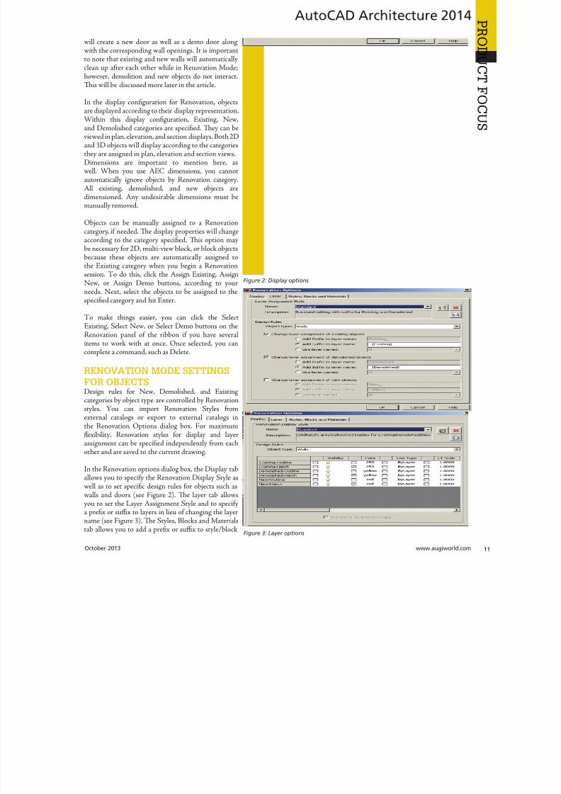
8122019 augi world 2013 10
httpslidepdfcomreaderfullaugi-world-2013-10 1152October 2013 wwwaugiworldcom
AutoCAD Architecture 2014
will create a new door as well as a demo door alongwith the corresponding wall openings It is importantto note that existing and new walls will automaticallyclean up after each other while in Renovation Modehowever demolition and new objects do not interactTis will be discussed more later in the article
In the display configuration for Renovation objectsare displayed according to their display representationWithin this display configuration Existing Newand Demolished categories are specified Tey can beviewed in plan elevation and section displays Both 2Dand 3D objects will display according to the categoriesthey are assigned in plan elevation and section viewsDimensions are important to mention here aswell When you use AEC dimensions you cannotautomatically ignore objects by Renovation categoryAll existing demolished and new objects aredimensioned Any undesirable dimensions must bemanually removed
Objects can be manually assigned to a Renovationcategory if needed Te display properties will changeaccording to the category specified Tis option maybe necessary for 2D multi-view block or block objectsbecause these objects are automatically assigned tothe Existing category when you begin a Renovationsession o do this click the Assign Existing AssignNew or Assign Demo buttons according to yourneeds Next select the objects to be assigned to thespecified category and hit Enter
o make things easier you can click the Select
Existing Select New or Select Demo buttons on theRenovation panel of the ribbon if you have severalitems to work with at once Once selected you cancomplete a command such as Delete
RENOVATION MODE SETTINGS
FOR OBJECTSDesign rules for New Demolished and Existingcategories by object type are controlled by Renovationstyles You can import Renovation Styles fromexternal catalogs or export to external catalogs inthe Renovation Options dialog box For maximumflexibility Renovation styles for display and layerassignment can be specified independently from eachother and are saved to the current drawing
In the Renovation options dialog box the Display taballows you to specify the Renovation Display Style aswell as to set specific design rules for objects such aswalls and doors (see Figure 2) Te layer tab allowsyou to set the Layer Assignment Style and to specifya prefix or suffix to layers in lieu of changing the layername (see Figure 3) Te Styles Blocks and Materialstab allows you to add a prefix or suffix to styleblock
Figure 2 Display options
Figure 3 Layer options
8122019 augi world 2013 10
httpslidepdfcomreaderfullaugi-world-2013-10 1252wwwaugicom October 20
AutoCAD Architecture 2014
PRO
DUCT
FOCUS
names to avoid naming conflicts between objects in differentRenovation categories (see Figure 4) Tis is much quicker thanhaving to manually rename each object When the DuplicateMaterial Definitions box is checked a copy of the material isautomatically generated and assigned to the building object Tecorresponding color settings will automatically display
ENDING A SESSION IN RENOVATION
MODEOnce you are finished working in Renovation Mode endingthe session is simple On the Renovation panel click the CloseRenovation Mode tool It is important to note that if changesare made to the drawing after Renovation Mode has ended theuncategorized objects are automatically assigned to the Existingcategory when you reactivate Renovation mode
MODIFYING THE RENOVATION DISPLAYYou can change how properties of objects within specific categoriesare displayed in the drawing by unlocking them changing themindividually per object type and saving them as the Renovationdisplay style Modifications made are saved to the current drawingTe lock icon to the left of the property signals whether thisproperty can be changed If the property is unlocked any changesmade to the display are reflected in the drawing
With the Renovation drawing open in an active Renovation modeclick Options on the Renovation panel Te Renovation Optionsdialog box displays On the Display tab select the display style toapply to the current drawing and enter a description Renovation
styles can be modified and saved deleted and imported fromexported to an external catalog Now select the object type fthe design rules and then select the checkbox to the left of eaproperty value for the category you want to change Modify tproperties as desired and select Prompt for objects to updatSelect the objects to modify or press Enter to select all objec
Changes to the selected properties for the specified objetype are applied in the current drawing
CONTINUING TO WORK IN
RENOVATION MODEWhen Renovation Mode is reactivated in your drawing texisting Renovation display configuration can still be used you can create a new one Te objects that were previouscategorized in an earlier Renovation phase will retain therepresentation and category Any objects that do not yhave a Renovation category will be automatically categorizand displayed as Existing objects Te ldquoShow existing neand demolished objectsrdquo option is automatically selected default It is recommended that this option remain selecteas it ensures that categorized objects in your Renovatioplan remain visible while switching between the DemolitioRenovation and Revision displays
o continue working in Renovation Mode select the Manatab on the ribbon then click the Style amp Display panand finally click Renovation Mode Tis will display tRepeated Activation of Renovation Mode dialog box (sFigure 5) Next you will need to specify the settings in tdialog depending on what you want to do o begin with existing Renovation display configuration click the drodown arrow next to Activate an Existing Renovation Displ
Configuration select the display you wish to use and cliOK o begin with a new display configuration select t
Create a New Renovation Display Configuration Named buttoenter a name for the new configuration and click OK Next yocan change the display style or design rules of objects by clickinthe Options button at the bottom left of the dialog box Click Owhen finished Ten click OK again to exit the dialog box You anow working in Renovation Mode again
Figure 4 Styles Blocks and Materials options
Figure 5 Repeated activation of Renovation Mode
8122019 augi world 2013 10
httpslidepdfcomreaderfullaugi-world-2013-10 1352
AUGI Members Prepare for the Future of Design
Join industry experts and design visionaries for 3 intensive days of classes andconversations on this yearrsquos hottest topics ndash 3D Printing BIM Cloud ServicesPLM Reality Capture and more
AUGI Highlights at AU 2013
bull AUGI Day Join the scavenger hunt and win great prices
bull AUGI Annual meeting and Beer Bust Get informed on AUGIprograms and planshellipand end the day with a cold brew
bull AUGI Top DAUG Contest Show your cerebral prowess the grandprize winner receives a free AU 2014 pass and HP notebook
bull Come visit the Community Pavilion on the Exhibit Floor to meetyour fellow professionals from the International Communities
Register starting September 12 2013 at httpauautodeskcom
Autodesk University 2013December 3-5 2013The Venetian Hotel Las Vegas
8122019 augi world 2013 10
httpslidepdfcomreaderfullaugi-world-2013-10 1452wwwaugicom October 20
PRO
DUCT
FOCUSAutoCAD Architecture 2013
ACTIVATING A DEMOLITION PLANTe display of a demolition plan shows existing construction andthose objects categorized as demolished All new objects howeverare hidden Display settings for the demolition plan type arelocated in the options dialog box for Renovation Mode
o create a demolition plan activate Renovation Mode as
previously discussed and then select the button for DemolitionPlan on the Renovation panel of the ribbon You can now selecta Renovation Display Configuration to activate Te box next toHide All New Objects is automatically checked If you want Newobjects to show while you are working in the drawing click in thebox to deselect the item and then click OK You can also click theNew ShowHide button on the Renovation panel You are nowready to begin creating a demolition plan
Please note that yellow is automatically assigned by default todemolition objects Tis can be changed in the options dialog boxfor Renovation mode under the Layer tab
ACTIVATING A REVISION PLANA revision plan displays new and existing construction objects butall demolition objects are hidden automatically Display settingsfor the revision plan type are located in the options dialog box forRenovation mode
o create a renovation plan activate Renovation Mode as previouslydiscussed and then select the button for Revision Plan on theRenovation panel of the ribbon You can now select a Revision
Plan Display configuration to activate Te box next to HiAll Demolished Objects is automatically checked If you waDemolition objects to show while you are working in the drawinclick the box next to deselect the item and then click OK You caalso click the Demo ShowHide button on the Renovation panYou are now ready to begin creating a revision plan
MANUAL MODIFICATIONSSometimes walls of different renovation categories do not intersecorrectly so manual modifications become necessary Tis can bdone by temporarily suspending Renovation mode For exampyou may have a plan that includes walls categorized as demolitioand walls categorized as existing with wall edges that need to corrected Remember objects categorized as New do not interawith objects categorized as Demolition When you need to maka manual correction you temporarily interrupt Renovation moby freezing the walls you want to modify and then correcting thedges Tese changes are not considered part of Renovation Toption to freeze or thaw walls is only available when Renovatiomode is active
Letrsquos make this a little clearer o do a manual modification clicthe Freeze Walls button on the Renovation panel of the ribboNext select the walls in question and hit Enter Renovation mois now temporarily suspended Proceed with correcting the wedges and then click Taw Walls when finished Renovatiomode resumes
RENOVATION STYLES CATALOGTe Renovation styles catalog contains display and layassignment styles AutoCAD Architecture-based styles for objecare managed with Style Manager By default the Renovation styl
catalog is installed in ProgramDataAutodeskACA ltversiongtenuStyles If the Renovation styles catalog is renamed or movethe styles are disabled and cannot be accessed Use the RenovatiStyles Catalog Settings dialog box to specify a valid catalog
With the Renovation drawing open in an active Renovation modclick Styles Catalog from the Options drop-down menu on tRenovation panel Te Renovation Styles Catalog Settings dialbox displays Select the Import renovation styles from catalcheckbox for drawings to be populated with all Renovation stylin the specified catalog Clear the Import renovation styles frocatalog checkbox for new drawings to include standard styles onlBrowse to the location of the Renovation styles catalog you wa
to use Click OK
Melinda Heavrin is a CAD Co-ordinator amp Facility Planner forNorton Healthcare in LouisvilleKentucky She has been usingAutoCAD Architecture since re-lease 2000 Melinda can be reached
for comments and questions atmelindaheavrinnortonhealthcareorg
Figure 6 Demolition dialog box
Figure 7 Revision dialog box
8122019 augi world 2013 10
httpslidepdfcomreaderfullaugi-world-2013-10 1552October 2013 wwwaugiworldcom
Inventor 2014by Mark Flayler
F
ree Autodesk Inventorreg apps You meanlike a Bloominrsquo Onion at Outback Countme in Wait you mean Inventor apps asin applications that change how Inventor
works for me and makes me more productive OkayIrsquom still in but I also still want some fried food
In this article we will take a look at severalof the free apps available in the AutodeskInventor Exchange store for trial purchase andSubscription customer benefits
DESIGN CHECKERTe first one we will take a look at is the DesignChecker that was previously called Validus and
sold through DMSI Autodesk purchased thissoftware in a manner similar to its purchaseof the iLogic code from Logimetrix a coupleyears ago Luckily I was a user back before thisacquisition so I know the tool pretty well Tefact that the software went from costing around$3000 to being a free tool delivered exclusivelyto Subscription customers is a really nice benefitfor having an Autodesk subscription right now
Te Inventor Design Checker is a productivitysolution that gives the designer insight into the
adherence of company or customer standards for
the product being designed Live Checking gives instant feedbackto the user and ensures a high level of quality for the entiredesign process
Users can use pre-defined checks or define custom checks withiLogic scripts to perform design checking Executing the on-
10 AppExchange
Reviews
Figure 1
8122019 augi world 2013 10
httpslidepdfcomreaderfullaugi-world-2013-10 1652wwwaugicom October 20
Inventor 2014
PRO
DUCT
FOCUS
demand checking updates the design checker results and enablingthe live-checking allows users to get the real-time feedback fromthe design checker during design process Te Design CheckerResults ree Browser allows users to interactively edit the objectswith failed checks and a Design Checker Results Report shows allthe passed and failed check results and allows users to export thereport to Excel Word or pdf or print the report
Now what I really enjoy about this tool is the iProperty checks andsome of the modeling checks Te machining checks I could livewithout mostly due to the fact that most companies try not to hireusers who make such drastic mistakes in machining operationsMy favorite thus far is the unconstrained sketches check thatvalidates my design before adding it to Vault I have also usedthis as a measuring stick before hiring new engineers or bringingvendor Inventor models into my design
AUTODESK REMOTETis next app allows some really nice RDP usefor Autodesk Inventor Autodesk Remote is astandalone application for Microsoft Window7 and 8 and is compatible with all Autodeskproducts It lets you drive Autodesk softwareinstalled on your primary computer from aremote computer or iPad for fast access to nativedesign data over standard networks o use itsimply install Autodesk Remote on the PC you
want to share Install it again on the machine youwant to connect from and start your connectionNote Autodesk Remote currently works only inNorth America
Autodesk Remote also has a companion applicationfor the iPad that allows you to access your hostPC from an iPad Te iPad app is optimized forAutodesk Inventor so you can work from anywhereimproving collaboration and increasing flexibilityDownlaod the iPad app from the Apple Store
Te controls in the iPad app are pretty easy to understand bthat doesnrsquot make a high-end CAD product made for the Pinstantly translatable to a touch interface You can see wheinterface elements of Inventor have started to lean more towarthis inevitable progression though
From my usage of the iPad app on my iPad 3 I found the usagelittle sluggish and gesturing a bit picky I found the use the ES
Figure 2
Figure 3
Figure 4
Figure 5
8122019 augi world 2013 10
httpslidepdfcomreaderfullaugi-world-2013-10 1752October 2013 wwwaugiworldcom
Inventor 2014
key a mandatory function as I often initiated one navigation tooland found myself trying to start something else before finishing thetool I was in In the end I see some fantastic usage on the horizonfor this app but right now it is pretty gimmicky for my taste I dopicture myself at some point on my front porch with my tabletinstead of my computer I would look cooler to the neighborhoodkids too
Be aware you will probably have to troubleshoot the setup of thisapp a bit I had to lock and unlock my computer and restart theapp several times before I got it just right
FEATURE RECOGNITIONTe Feature Recognition application converts neutral 3D CAD
models such as SEP SA or IGES solids into full-featuredAutodesk Inventor models Feature mapping could be executedautomatically or interactively as needed to maintain design intentCurrently there is one Automatic Feature Recognition commandand eight feature recognition commands you can use
Automatic Feature Recognition attempts to recognize specificfeature types and populate the browser tree with the recognizedfeatures A dialog box displays the feature types you can recognizein the Features section with the defaults checked You can selectfeatures you want to recognize and deselect features you do notwant to recognize
When you import a file it will offer to start feature recognition Ifyou decide to do it later you will have to find your Base1 solid inyour tree and right click on it to start it again
Tis tool has been around for a long time previously only on
Autodesk Labs Personally I donrsquot like it mainly because I have toconstrain and dimension the sketches when they get recognized bythe tool If your goal is to bring in a solid and then do some minormodifications to it then you are better off using the Edit Solidtools also shown in the image above If you want Work Plane toolsalso remember to turn off the Import into Repair Environment aswell before opening the file
If you really had to go the distance and recognize features it isactually a lot quicker and generally creates a more intelligentmodeling history if you just redo it yourself in Inventor Terecognition tools only lend themselves to simple parts inmost cases
Figure 6
Figure 7
Figure 8
Figure 9
8122019 augi world 2013 10
httpslidepdfcomreaderfullaugi-world-2013-10 1852wwwaugicom October 20
Inventor 2014
PRO
DUCT
FOCUS
WORK FEATURE VISIBILITYTis product allows Inventor users to manage all work featurevisibility in a fast and easy way keeping full awareness of the involvedentities Tis app consists of six buttons on part environment andanother six on assembly environment Inside of part environmenta user can choose to enable or disable the visibility property ofplanes axes or points Inside of assembly environment a user can
also choose on which components to enable or disable the visibilityproperty of planes axes or points
I had a little trouble with this app in the assembly environmentbut that was due to some bad installation files Tis is one appreally worth the $099 How often have you been in an assemblyand not wanted to go back to the part files to turn on and offwork features I recommend ungrouping them so you access bothcommands faster
SHEET METAL FLAT EXPORTTere seems to be a plethora of these apps on the Exchange witheach of them varying in price and options In general the ideabehind these apps is to help automate the process of getting a DXF
to a machine that reads them for manufacturing in a more efficientmanner Tese programs will scan an assembly file and find thesheet metal files on which to perform their routines
Te different variations of this program range from free trialsupwards of $100 for the paid apps I started with one that gave me
a ldquoliterdquo version that would do 20 sheet metal files and I liked it much I started using the full version
FEATURE MIGRATORTe Feature Migrator tool allows Inventor users to more eascreate part features from assembly features User can migraassembly features either by selecting them in the Feature Migratbrowser or by right-clicking on one or several of them and theusing the ldquoSend to Partsrdquo commands Features can also be directmigrated from the regular Inventor model browser using thcontext menu item added by the add-in
Once the operation of migrating features is completed the FeatuMigrator displays a dialog that provides information about thresults Tis first dialog is a ldquohigh-levelrdquo report of the migrationprovides the opportunity for the user to select the action to takfor all the assembly features migrated Suppress if SucceedeSuppress always Delete if Succeeded Delete always or Nothingalso for the part features that havenrsquot been migrated correctSuppress Delete or Nothing Features created by the add-in cbe in an invalid state in the parts for a number of reasons
Te user can also see when a feature is out of date from thassembly and perform updates from the part side
Figure 10
Figure 11
Figure 12
8122019 augi world 2013 10
httpslidepdfcomreaderfullaugi-world-2013-10 1952
8122019 augi world 2013 10
httpslidepdfcomreaderfullaugi-world-2013-10 2052wwwaugicom October 20
Inventor 2014
PRO
DUCT
FOCUS
TIME STAMPime Stamp is an Autodesk Inventor add-in that provides bull A low-cost simple-to-use tool that adds plot time information
to your printsbull A plot stamp that does not dirty the Inventor drawing
documentbull
A simple dockable user interface that keeps out of the way
Te ime Stamp editor lets you size position and orient thestamp relative to the adjacent sheet edges You can include datetime and current user information in the stamp Te time stamponly appears on the plot it does not alter the Inventor drawing
What I really like about this app even though it costs $500 perlicense is that you can find the price yourself and buy it It doeseverything it says it does and it provides an easy-to-use interfacewith an icon that changes based on whether the tool is on or offIf you want even more control over your plot stamping there is amore professional version offered by this company on their websitefor about $4000 a license which will allow more reporting fieldsand more control on the look and location of the stamp
SIMPLE SHEET SETTINGSSimple Sheet Settings combines the existing sheet settings withsome new tools such as changing the title block and also the abilityto make changes to all sheets in a document at once
Instead of first deleting the existing title block from a sheetexpanding the title block folder and inserting the desired titleblock then opening another window to change the sheet size andorientation just click the ldquoSettingsrdquo button located on the Sheetspanel in the Placed Views tab (right next to ldquoNew Sheetrdquo) andhave access to all those options in one location
When the Simple Sheet Settings window is loaded it gathers all the existing title block names and puts them into one drop-dowmenu o change the title block on the current sheet simply selethe desired title block from the drop-down menu and click OKTere is also the ability to change the title block sheet size ansheet orientation to all sheets at one time
Tis is a great little app that saves clicks and only costs a dollaQuite useful and no real setup involved
INTERACTIVE TUTORIALTe Create an Interactive utorial app provides instructions fcreating your own interactive Inventor tutorial Te Guide alincludes how to customize the Welcome Screen to display yointeractive tutorial and add to the ribbon
Tis one definitely falls under the ldquotoo much time on your handuser or CAD admin After reading through the guide on how create the interactive tutorials you find yourself asking the questioldquoWhy donrsquot I just save videos of the process we use in a companserver locationrdquo And that is when you uninstall this app as yohave realized that while it sounded good to you at first there abetter ways to accomplish the goal of company-specific tutoria
and process documentation
Figure 16
Figure 17
8122019 augi world 2013 10
httpslidepdfcomreaderfullaugi-world-2013-10 2152October 2013 wwwaugiworldcom
Inventor 2014
Te tools actually rely on too much externally controlled softwaresuch as Camtasia and other plug-ins and third-party apps to makeit work correctly Save your time and just use Camtasia from
echsmith to do your bidding
KEEPING UP TO DATEWith all these apps it is easy to understand how a user could getbehind on the updates to so many tools With that in mind theExchange Manager found on the ools tab in Inventor will keeptrack of that for you and offer assistance not only in updating butalso uninstalling and specialized help for each app
As a reminder with regard to third-party apps if you startexperiencing undesired effects in Inventor start turning add-ins
off one by one until you isolate which one is giving you fits Properreporting back on the app to the developers makes everyonehappier when the issue gets resolved Tus far I havenrsquot had nearas many issues as I thought I would have
ANY MANY MOREWith 80+ apps currently in the store and about 60 of them ready
for 2014 at the time of this article you should take some time andlook through what is available Tere are apps which are very nicheto the user base as well as those that have you scratching your headover why they are not already part of the core software Below aresome I would write about if I had more room in the article andora fatter PayPal walletbull BOM oolsbull EDM Expressbull Sketch Symbol Librarybull SolidWorks iProperty Importbull Quick Viewsbull 3D Pipebull Point Linkerbull Kwikools
Mark Flayler is an application engi-neer with IMAGINi echnologiesspecializing in manufacturing environ-ments He has implemented Autodeskmanufacturing products within severalindustries including the blowinjectionmolding automotive and custom ma-chinery markets When not providingtraining support and implementationhe writes the IMAGINi Manufac-turing Blog and takes an active role inthe manufacturing community Markis an AC certified instructor and isPSE and AC certified in AutoCADAutoCAD Mechanical AutoCADElectrical Autodesk Data Manage-ment and Autodesk Inventor
Figure 18
Figure 19
8122019 augi world 2013 10
httpslidepdfcomreaderfullaugi-world-2013-10 2252wwwaugicom October 20
SPECIALFEATUREAUGI Forums by Melanie Perr
The AUGI Forums are as always a busyplace Ask a question and you mightsee half a dozen varied methods andworkarounds posted in a single thread If
you have not had any questions yourself I would stilllike to encourage you to pop into the Forums and see
if there are any problems you could solve especially if you use one
of the less adopted products Tere will always be many helpinghands in the AutoCAD and Revit Forums but what about themechanical products or design visualization or structural detailingForums Peek in and see if you can share your experiences andwisdom with the community
I confess that I only scoured the English-speaking Forums forcontent for this article but please keep in mind that there areAUGI Forums available in 12 other languages so users have theoption of asking for support in their native tongue
AUTOCAD ndash SYSTEM VARIABLE
DISCUSSIONhttpbitly15M1hB9
Tis topic started out when a user couldnrsquot delete Te solution wasultimately the PICKFIRS variable but the discussion evolved tosafeguarding other variables automatically just to protect against aloss of settings in the event of a crash User Coloradomrg offeredthe safeguard shown in figure 1
Norton_cad also suggestsDIMLFAC EXPER andBLIPMODE be addedto the list
REVIT ndash
UNDERLAY
BEHAVIOR
EXPLAINEDhttpbitly15M1iFd
Mschroeder opened thediscussion with If you haveever wondered why some wallsdonrsquot show up in underlays or
show up inconsistently from floor to floor or why roofs and vieranges affect their behavior then read on
First rule of underlays Underlay view extent properties (cut rangdepth) are not user modifiable and not coupled to any othviewrsquos properties
Itrsquos also been mentioned ldquoIf objects are visible in the view ranof your current view AND in the view range of your Underlathey are automatically hidden in your underlay so there isnrsquotdouble instancerdquo
Users twiceroadsfool and dbaldacchino helped clarify the effecby posting sample models and pertinent data from the AutodeKnowledgebase and Autodesk Support Visibility View RangDetail Level and Cut Planes are all touched on in this discussioNeed clarity on how to make the most of Underlays Check inthis thread on the Forums
LISP ndash MAKING A DIALOG BOX RETAIN
ITS SELECTIONShttpbitly15JzMCc
Te LISP Forum always has such fascinating topics it is hato decide which to highlight From locking OSNAP options setting Explode options along with troubleshooting of existincode But the discussion surrounding the tutorials and metho
to retain selectioin a dialog box wvaried and lively so had to check it ou r e a v e s 0 4 4 1 3 2 1
even posted a sampdcl file when he wfinished
String Theory
8122019 augi world 2013 10
httpslidepdfcomreaderfullaugi-world-2013-10 2352October 2013 wwwaugiworldcom
AUGI Forums
AUTOCAD ELECTRICAL ndash LINES BEING
LABELED AS WIREShttpbitly1ew9p9D
Dinochrome says that one of his coworkers has reported aproblem with regular AutoCAD lines being labeled as wires
Crosswire35 advises ry checking your wire type edit dialogbox and make sure the ldquomake all lines valid wiresrdquo checkbox is unchecked
And IMCO goes on to say Using the vanilla line command inACADE will still place that line on a wire layer Change your linesto layer 0 and ACADE will not give them a wire number
AUTOCAD STRUCTURAL DETAILING ndash
TUTORIALShttpbitly17kW7cc
Te consensus is that this product is a little confusing to figure outand that most of the tutorials out there are older Most productshave a few videos floating around on Youube but this one doesnot seem to have too many yet
Jpo82 chimes in with I guess only tutorials forthis software are those found at Autodesk websiteTey are for versions 2010 and 2011 but still validhttpusaautodeskcomadskservlet12ampid=13111928 Irsquom not sure but sometimes I feel that the only new feature inASD 2013 is that itrsquos more stable than previous releases
Lucis29 goes on to say Also you might check some movieshttpwwwrobotofficecomasd but they are very old
Spenner then linked to his reporting of the Service Pack andissues it addressed hoping that it addressed some of the issuesthat came up in this discussion
NAVISWORKS ndash IMPROVE ANIMATION
EXPORT QUALITYhttpbitly1fQLoIv
Different methods are discussed from exporting individual imageframes to exporting a video (and how long) but I will leave youwith the following list from Revit For Breakfast
Here are the secrets to movies in Navisworks1 Donrsquot use materials ndash you make your render time much longer2 Use the PNG export option 15fps3 Make your video export twice as long as you need Ten speed it
up for a faux 30fps Tis is faster4 Look up the Navisworks blog by Lee Mullin and Paul Walker
about gooch and phong Tere is your faux render setting5 If you have NW 2012 you wonrsquot have gooch or phong but you
will have better export options 2013 has gooch and Phong butfewer export options
6 Te flickering occurs when multiple shapes overlap If you care
delete them in your export model Sometimes flickering occurs
in the generation of your frames on the PNG export You mayhave a frame that is ldquooffrdquo
7 Set your anti-aliasing to 4x or better on the png export8 Check out my old post httpforumsaugicomshowthread
php132209-Animation-Resolutionampp=1138298ampviewfull=1post1138298
CAD MANAGEMENT ndash NETWORK DRIVE
CHANGED BY IT WITHOUT WARNINGhttpbitly18J4k9c
Blackbox advises edinsmore595165 straight off to utilize theReference Manager program that comes with AutoCAD inorder to reconnect all of the external reference paths that werebroken when the I department upgraded their archaic serversHe further points out that moving from hard pathing to relativepathing would make things easier in the future
Feargt offers another twist Another option which would workon a need only basis when you open the specific drawing Change
XREF and Image paths in drawing to Network path throughscript on a need only basis Basically this will only change pathsPlace this line in a acaddoclsp file(command ldquoscriptrdquo ldquoyourserver and pathXREFREDIRECscrrdquo)and the following in a script fileREDIRB enter name of path to be replacedP enter new path
Tere was also a debate in this thread about obstacles and benefitsof user-managed and I-managed drive mapping
Melanie Perry is a Facilites-Manage-ment Coordinator and echnical Edi-tor in St Louis MO She is the AUGISalary Survey Manager and is curring-ly serving as an Officer on the Board ofDirectors Melanie can be reached atmistressofthedorknessgmailcomor found on witter asMistresDorkness
OTHER HOT TOPICSHave you found a Forum solution so mind-bogglinglyuseful that you leapt out of your chair with a whoopingcheer (or were at least tempted to) Please let me know Asingle person cannot read every post in our bustling AUGIForums so if you would like to see a thread highlighted ina future edition of String Teory feel free to let me knowSend me Wanderer a PM in the Forums or send an emailto MelaniePerryaugicom
See you on the Forums
8122019 augi world 2013 10
httpslidepdfcomreaderfullaugi-world-2013-10 2452wwwaugicom October 20
Revit Architecture 2014
PRO
DUCT
FOCUS
by Martijn de Rie
Myth Buster
Revit amp IFCPart 3
Irsquove given a lot of thought as to how this trilogyof articles should end At first I thought Irsquoduse the Coordination View 20 EXPRESS-GWallPaper for IFC2x3 (httpwwwmdr-
adviesnlwp-contentuploadsCoordinationView_V2-0_WallPaper_IFC2X3_Version-1pdf ) as a stepping stoneto give an ldquoIFC for Dummiesrdquo type of solution But that turnedout to be quite lengthy and rather boring But the link is includedabove for obvious reasonsmdashitrsquos useful
So I went back a little and asked myself ldquoWhy IFCrdquo And with thatquestion the inevitable follow-up immediately appeared ldquoWhynot IFCrdquo I realized that in the previous articles I failed to explainwhy in my humble opinion we should care about this somewhatcrooked badly implemented severe headache-inducing formatTerefore instead of explaining the fundamental technicalities ofIFC that can be explored in other places this final installment willexplore the Why versus Why Not IFC discussion and begin withthe latter
WHY NOT IFCWhen everybody uses Autodeskreg RevitregWell in this case itrsquos a no-brainer Share your Revit files Period
Loss of dataTis is an easier way to share data instead of hacking your wthrough IFC and praying your stuff doesnrsquot get lost in the proce
Even when you manage to export your geometry through IFtherersquos always loss of data
Loss of intelligence during importEven if you only need to send over geometry not data importithat into Revit makes it utterly useless All constraints are locomponent parametrics are gone and so on
Availability of bidirectional linksWhen not everyone uses Revit on a given project (which is quoften when yoursquore not located in the US) why not simply ua bidirectional linking between proprietary software standardTis can be easier and better to control
8122019 augi world 2013 10
httpslidepdfcomreaderfullaugi-world-2013-10 2552October 2013 wwwaugiworldcom
Revit Architecture 2014
WHY IFCWhich may be asked as why would you want to use IFC Or moreaccurately why would you want that option available
Consider what Sir Arthur Conan Doyle wrote ldquoOnce you eliminatethe impossible whatever remains no matter how improbablemust be the truthrdquo
Letrsquos put that to the test shall we
When everybody uses RevitOkay simple math Autodesk has around 7000 employees Teworld has about 72 billion people What are the chances someonenot working for Autodesk has a brilliant idea and creates thesoftware you need tomorrow Tere will always be better solutionsTey might not be viable for you overall but therersquos no reason toshut down access to them Revit is a wonderful generic tool forwhich I see a brilliant future with all kinds of additions for specificniche-markets like AutoCAD has
What about today DDS is MEP-engineering software that cando energy calculations (not simulations) inside your modelRhino lets you model things on the fly that could (arguably)take ages in Revitmdashif you ever get them done ekla lays wasteto the Revit structural rebar functionality any day of the weekwithout breaking a sweat Solibri is a wonderful solution for clashdetection and most importantly rule-based model checking andreportingmdashsomething Revit (or Navisworks) doesnrsquot do
Should I go on
Only problem for all this magnificent software Itrsquos either based onthe IFC format or requires model exchange through IFC
Te fact of the matter is there will always be better softwareAny one may be the software for you but that doesnrsquot mean yourpartners associates etc need to have the choice to use it forcedupon them
Loss of dataOn July 1 2013 there was an extra release for Autodesk softwareTe Sourceforge Open Source IFC Exporter released a new versionthat incorporated the option to map custom Revit parameters(shared or non-shared family or project even calculated values) totheir IFC counterparts
On September 28 2013 I had the honor of showing the secondstep in a complete and controllable data export from Revit
During my RC Europe class I showed the new option to create acustom IFC Property Set and map any given Revit parameter intoIFC fully customizable
IFC does not automatically lead to loss of data Tat idea is simplynot true Incomplete implementation in Revit does lead to loss ofdata As of now you are able to put any piece of data into an IFCeven calculated values And we didnrsquot change the IFC format We
just improved implementation in Revit
Loss of intelligence during importldquoJust because something hasnrsquot happened yet doesnrsquot meanitrsquos impossiblerdquo
I donrsquot know who originally had this insight and I doubt it to bethe movie line I remember but it is true
In the same RC Europe class I showed a native Revit familybeing exported to IFC altered and re-importedmdashwhile keepingall parametric constraints and even adjusting to the alterationsmade directly in the IFC file It is possible but not with thecurrent importer
Availability of bidirectional linksIrsquove been using Revit for almost 10 years now For 4-5 years I didnrsquotknow about IFC at all Before a year ago this was my strongestargument against IFC Why would you need a generic ldquolanguagerdquowith all its limitations (of which there are) weaker implementationand use of parametric capabilities (because it has) and lag-times indevelopment (by nature)
IFC will never be able to do what native software does simplybecause itrsquos responsive in nature Development budgets are afraction of what Autodesk rimble or Nemetschek get to spendon their software
So why not keep it simple and use a bidirectional link Revit has itwith a lot of other Autodesk software and third-party applications
But how long have we waited for them And are they even trulybidirectional Do they exactly do what you want them to do In myhumble opinion the answer to these questions is not very inspiringEven bidirectional links tend to have major limitations and severe
constraints in flexibility And most important Te link itself isalso propriety software No way of adjusting it to your needs
WHAT IF MORE PEOPLE STOPPED
TALKING ABOUT IT AND JUST GOT
INVOLVEDTe improbableFirst off itrsquos a matter of simple logic As Sir Arthur suggested ifwe can successfully check off all likely options to NO want touse IFC doesnrsquot that mean the improbable is true Tat IFC is infact a valuable tool in our toolkit and we should be able to use it
when necessary
Mind you Irsquom not saying you should use IFC If yoursquore on a Revit-only project it would be insane Just send and receive RVs Tefact is this will only be viable for limited parts of the buildinglifecycle If yoursquore lucky the entire design team is on Revit Butmanufacturers have other software facility managers too
As for the design team what if the best structural engineer is not[on Revit] or the MEP guy that has loads of experience in similarprojects Would you settle for second-best just because someoneuses the same brand of tools you do I wouldnrsquot
8122019 augi world 2013 10
httpslidepdfcomreaderfullaugi-world-2013-10 2652wwwaugicom October 20
PRO
DUCT
FOCUS
Revit Architecture 2013
Open AccessWhich brings us to the biggest advantage of IFC (or any open
format) itrsquos open Which means itrsquos adjustable to your needs Nowdonrsquot go ldquothatrsquos too difficult expensiverdquo Tatrsquos bullocks
Te first external enhancement to the Open Source Exporter wascreated by om Pesman a self-employed API specialist
Parametric IFCImplemented by Jon Mirtschin also self-employed IFCparametrics is available Agreed Jon is a well-known IFC guru butstill the point holds
Custom property sets and parametersWim as owner of a small MEP engineering firm hasadded functionalities toward this end and hersquos not even a trueAPI specialist
All these developments were done for free by altruistic volunteerefforts as part of the creation of the Dutch Revit Standards Andof course with the invaluable help of the Autodesk Open SourceIFC Exporter team Angel Velez in particular
But what if these guys actually got paid What if this projectwasnrsquot a Saturday night side-job What if more people stoppedtalking about it and just got involvedmdasheither by themselves or byleveraging experts to get what is needed Te entire IFC format is
Open Source the source code is out there which basically meansyou can do whatever you want and create whatever you needmdasheven on a project-by-project basis
BIM ITrsquoS THE ldquoIrdquo THAT MATTERSIn my humble opinion the entire debate on BIM is focusing on thewrong part of the acronym I donrsquot care if ldquoBuildingrdquo is a noun ora verb Nor do I care whether itrsquos ldquoModelrdquo or ldquoModelingrdquo nor am Icommenting on whether one should say ldquoBIM Modelrdquo
Itrsquos the ldquoIrdquo that matters If wersquore collaborating the Informationis most all I care about I just want your datamdashin the leanest
smartest and most effective way possible
A Revit model will do conversely a lot of times A Revit model w
give me heaps of data I donrsquot want geometry I donrsquot care about ana file format I canrsquot use Now we can all keep on being really anabout it or we can simply use the tools available to us one of thebeing IFC
A FINAL NOTEAs stated at the beginning of the article I really enjoyed writinthis series and for now this is the last of the series But if yoursquointerested in more tips and tricks on IFC let me know I might able to persuade the guys at AUGI to let me write about it againLord knows there is still a lot to talk about regarding IFC
Martijn de Riet is a self-employedBIM Consultant from the Nether-lands working with Revit since version51 Martijn has a bachelor degree inBuilding Science After his studieshe started his own engineering firmworking for contractors architects and
private clients Starting in 2007 hiscompany transformed into a full-timeBIM consultancy service At the mo-ment Martijnrsquos clients vary from mid-sized architectural firms to the largest
dutch General Contracter and MEPEngineering firms with a focus onspecific corporate solutions design andimplementations of Revit and BIMworkflows Martijn is a member ofthe Dutch Revit User Group and cur-rently working on creating a Masteremplate and Component LibraryHe provides lectures for companiestechnical universities seminars etc ona regular basis
Itrsquos the ldquoIrdquo that matters If wersquore collaborating the Information is most all I care about I justwant your datamdashin the leanest smartest and
most effective way possible
8122019 augi world 2013 10
httpslidepdfcomreaderfullaugi-world-2013-10 2752
wwwxicomputercom
8122019 augi world 2013 10
httpslidepdfcomreaderfullaugi-world-2013-10 2852wwwaugicom October 20
3ds Max 2014
PRO
DUCT
FOCUS
by Chris Murra
SUMMARY WHATrsquoS
CUSTOMIZABLE IN MAX
(HIGH LEVEL)When it comes to the customizability of Autodesk 3ds Maxregitrsquos no secret that it can morph itself into whatever you want theprogram to become
Whether yoursquore a modeler animator lighter rigger generalist ortechnical artist 3ds Max can become your own personalized toolbox that is an extension of your own hand in your daily workYou can now combine different command types (such as creatingobjects and object modifiers) into a single menu reducing themouse travel and improving efficiency
In this article wersquore going to take a closer look at one specificaspect of customization with 3ds Max the new enhanced UI Aspart of this article besides taking a deep dive into the operationof this feature I will also be showing how I created the ldquoMographrdquo
tools UI that includes custom buttons and icons At the end this article I will also provide a link to this UI so you can use customize it yourself or share it with others
ENHANCED UI SUMMARYWhat is the Enhanced UI
Te Enhanced UI is a new graphical user interface system thdoes two main things
1) It provides a refreshed 3ds Max user interface with updattool categories and new clusters of pre-existing tools in groupinthat are more akin to their intended purpose as opposed to somtechnical requirement for menu placement
2) It provides a way to allow you the end user to customize thmenu system in almost any way you choose Te drop-down menare ldquotear-ablerdquo (not to be confused with ldquoterriblerdquohellip but I digresand the resulting configurations are savable either by scene or
3ds MaxEssentialsCustomizing
the UI
8122019 augi world 2013 10
httpslidepdfcomreaderfullaugi-world-2013-10 2952October 2013 wwwaugiworldcom
3ds Max 2014
a preset Tey are also distributable and deployable so they can beshared with others
Where is the Enhanced UITe Enhanced UI can be found in the upper left hand corner of themain UI at the very top of the screen Tere is a drop-down menuthat says ldquoWorkspace Defaultrdquo Tis default is the same baselineUI that ships with all 3ds Max installs (Figure 1)
Within the drop-down you can find the ldquoDefault with EnhancedMenusrdquo Tis is the alternative default menu system that youcan use on its own or use as a starting point to create your owncustomized menus
BASIC DEFAULT CUSTOMIZATIONEnhanced UI Customization BasicsNow that wersquove enabled the Enhanced UI how can we change it
SOP Before you begin mucking around with the UI Itrsquos importantto understand what I call the ldquosave-logicrdquo as it pertains to custom UIs
Te UI Save LogicIf you plan on saving this UI for future use there is a specificmethod you must follow to properly save the UI you want and notwreck the default Enhanced UI
Te Save Logic is as follows Itrsquos simple but important
Step 1 urn on Enhanced Default UI (Figure 3)
Step 2 Click ldquoSave as New Workspacerdquo FIRS At this point youwill be prompted for a new name (Figure 4)
Step 3 Edit and change the UI at will
NOE All future edits are ldquoautomatically rememberedrdquo as you go (Iintentionally did not use the word ldquosaverdquo)
Step 4 Te ldquosave as default staterdquo button is important When wehave completed the customization process we then choose thisbutton to ldquolockrdquo in the changes Tis is different than Saving a UIwith a custom name
HO IP ldquoBut this methodology seems backwardrdquo
I can see how yoursquod say that but remember that any changes you make
to any enhanced UI are automatically ldquorememberedrdquo If you create acustom UI then while working you make some temporary changeswhen doing something specific those little changes are automaticallyremembered If you want to return to the default state [of yourcustomized UI] you select ldquoReset to default staterdquo Tis does NObring back the default Max UI rather it brings back the customizedUI you created in ldquolockedrdquo in Step 4
Okay now that you have the save logic down letrsquos begin customizing
1) If you havenrsquot done so already turn on the Default Enhanced UI
2) Go to ldquoManage workspacesrdquo from the drop-down and in the
Figure 1 Workspaces are in the Workspace drop-down menu
Figure 2 Default UI (left) and the Default Enhanced UI (right)
Figure 4 Saving the New UI Workspace
Figure 3 Turning on the Enhanced Default UI
8122019 augi world 2013 10
httpslidepdfcomreaderfullaugi-world-2013-10 3052wwwaugicom October 20
3ds Max 2014
PRO
DUCT
FOCUS
Manage workspaces dialog choose ldquoSave as new Workspacerdquo Giveit a specific name
3) Begin making your desired changes
Since a custom UI is specific to any one individual letrsquos take a lookat what types of customizations can be made
Simple ChangesOne of the simplest things to do is peel off any commandgroup (see Figure 5) Just click the group title bar and drag Tecommand group becomes a floating dialog box Now just becauseyoursquove peeled it off does not mean that yoursquove removed it fromthe drop-down menu Te ldquooriginalrdquo command group remains inthe drop-down You can just close the floating dialog when yoursquoredone with it
Probably the simplest thing you can do is reorganize the menusIn each drop-down menu appears a group of commands You maynotice that some command groups are icons and some are words(Figure 6) o change the appearance of the commands there is asmall icon in the upper right corner of each group of commands(Figure 7)
Te next change is alreally simple Is tcommand group op(expanded) or clos(rolled up) Just clion the plus or minsign in the upper le
corner to set this stafor the next time yolaunch 3ds Max (Figu8) Remember thesettings are saved as yogo so whether it is opor closed is your choicbut the state the menis in when you cloMax is the one that remembered the netime Max opens
What about Saving tDefault state More othis later
Once you have floating menu yocan combine differecommand groups dragging any othcommand group to aother floating dial
that yoursquove created Tis makes for easy creation of custom dialo
based on specific tasks Figure 9 shows a command group fcharacter animationFigure 5 A floating menu that has been torn off the drop-downmenu
Figure 6 The different display states of the menus
Figure 7 Changing menu layouts
Figure 8 Rollouts
8122019 augi world 2013 10
httpslidepdfcomreaderfullaugi-world-2013-10 3152October 2013 wwwaugiworldcom
3ds Max 2014
ADVANCED CUSTOMIZATION
What about completely custom interfaces Herersquos how we do thatwith the Enhanced UI menu system
Te following is the high-level overview of the process Wersquoll thenunpack each step in more detail
If you havenrsquot read the section on Basic default customizationplease do so before continuing Before starting this phase ofcreating your new UI you should have saved your new UI stateTat process is explained in the previous section
1) Create a main drop-down menu (like ldquoMy oolsrdquo)
2) Create a tools category menu into which you will place yourtools (a submenu such as ldquoModeling oolsrdquo or ldquoAnimation oolsrdquo)Drop-downs can have more than one subcategory
3) Add commands to various submenus
4) Clean up the UI by creating custom names adding separatorsor creating custom icons
First letrsquos create a new menu for the menu bar Tis is done easilyfrom the CustomizegtCustomize [Rollout]gtCustomize UserInterface dialog box
Steps for Creating a Drop-Down Menu1) Create a New Menu and give it a name (see Figure 10)
2) Locate your new menu in the Menus window It will be listedalphabetically (Figure 11)
Figure 9 Multiple command groups in one menu
Figure 10 ndash Creating a new drop down menu
Figure 11 Location of new menu
8122019 augi world 2013 10
httpslidepdfcomreaderfullaugi-world-2013-10 3252wwwaugicom October 20
3ds Max 2014
PRO
DUCT
FOCUS
3) Drag your newly created menu category over to the column onthe right Tis will add your new drop-down menu to the interfaceimmediately and you can begin populating it with menu items (seeFigure 12)
UI DESIGN IP Te actual menu name and display name can bedifferent I used a custom menu name behind the scenes so I couldeasily differentiate my menus from the ones created by default or other
tool companies After you create a menu and add it to the right column you can right-click on it and change its display name (see Figure 13)
Next letrsquos create a command group1) Just like in Step 1 from the previous section create a new men
2) Tis time before you drag it to the right column click thplus sign next to your drop-down menu item to expand it Tedrag the new item to the right column dropping it ldquounderrdquo thmenu name
3) Drag any commands from the Commands window on the leto the submenu on the right (see Figure 15)
Herersquos an example from my Mograph ools workspace thshows how a completed menu looks once it is created (Figu16) In the following figure you see both the menu as it appeain the Customize UI dialog and the actual menu (which has bepeeled off)
Notice that some of the commands on the menu are greyed ouTatrsquos because this new menu combines both ldquoObject creatcommands and ldquoObject Modify Commandsrdquo in one menTey will remain grey until you create an object on which thwill be used
Figure 12 Adding the new menu to the UI
Figure 14 Creating a command group
Figure 15 Dragging commands onto the menu
Figure 13 Custom menu names
8122019 augi world 2013 10
httpslidepdfcomreaderfullaugi-world-2013-10 3352October 2013 wwwaugiworldcom
3ds Max 2014
Adding SeparatorsSeparating commands is easy and is recommended to help you oryour intended user make sense of the how the tools are arranged inthe menu Creating a separator is as easy as dragging one over theright column just like a menu or command
HO IP ldquoWhy do I need to create another menu Why canrsquot I addtools right to my menurdquo
Te main reason is that adding a submenu gives you the ability to tearoff the submenu If it werenrsquot in a submenu it wouldnrsquot be tear-ableSo itrsquos really a ldquobest practicesrdquo kind of thing But even if you try to notadd the submenu it will happen automatically Itrsquos important to do it
explicitly so you are aware of what submenus are in the menu and that you are the one in control of what command is going where
CUSTOM ICONSNo custom UI is complete without a custom set of iconsAdditionally not all commands in 3ds Max have their own iconyet But itrsquos important to realize that regardless of how you set up
your UI yoursquore still working within the framework of an existingapplication and there are boundaries to what you can edit andcreate Icons have specific requirements both in their creation(size) location and file name that must be adhered to in order forthem to work properly
SizeformatTe size of icon is pretty simple It must be 32x32 pixels andPNG format
LocationTe location is very specific New icons must be added to thislocation
CProgram FilesAutodesk3ds Max 2014UI_lnResourcesDarkIconsMain
Te new icons I created for the Mograph UI are shown inFigure 17)
Icon File NameIf yoursquore still with me at this point we are now getting into thenether regions of customizing a UI Tis is where things get a littletricky but itrsquos really not too bad File names are specific and aregenerated by the application (3ds Max)
So letrsquos begin First identify the command for which you want aniconmdashusually itrsquos one that doesnrsquot already have an icon But if itdoes and yoursquore changing it MAKE A BACK UP of the originalicon PNG file Tis is because as previously stated you donrsquot havecontrol over the file name Tat means if yoursquore creating your ownicon you need to overwrite the existing one and use its name foryour new icon So back up any original icons
Figure 16 The completed menu
Figure 17 ndash The created icons
8122019 augi world 2013 10
httpslidepdfcomreaderfullaugi-world-2013-10 3452wwwaugicom October 20
3ds Max 2014
PRO
DUCT
FOCUS
It really doesnrsquot matter whether you make the icon first or not ofind the name you need to use you need to navigate as follows
NOE Yoursquore about to edit the ribbon Tere is no need to save thesechanges as we are merely extracting information from it But if yoursquoredoing a lot of custom icon work you may want to save this change to theribbon so you can come back and continue your work in later sessionswithout have to recreate this every time just to get the proper file nameSaving this ribbon is not related to saving your default state of yourUI When yoursquore done creating all your UI icons you can just delete
whatever changes you make to the ribbon
1) Open the ldquoCustomize Ribbonrdquo dialog box
2) Create a new ldquotabrdquo by dragging it onto the ldquoExisting Ucolumn in the middle (see Figure 18)
3) Using the same drag method add a new ldquopanelrdquo to ttemp tab (Figure 19)
4) Now you can get the information you need Find tcommand for which you are creating an icon and dragto the panel
5) Locate the ldquoinfordquo portion of the ldquoPreview Windocolumn At the bottom of the column is the file namneeded to have the icon used properly by the applicati(Figure 20)
CONCLUSIONSo now you know how to create a custom UI scheme f3ds Max 2014 and up By using the Enhanced UI me
system itrsquos really easy to generate a multitude of workspathat allow Max to work the way you want to work
Te example used in this article was the ldquoMographrdquo UI thI created for NAB 2013 If you would like to downloand install it you can get it from my ldquoPinning the Stacblog on the Area herehttpareaautodeskcomblogschrismurray
Enjoy
Chris Murray works for Autodesk
Media amp Entertainment He istrained as an animator (3D variety)but considers himself a creative tech-nologist His daily role is a technicalldquoevangelistrdquo for Autodesk creating marketing deliverables for 3ds Max Heis the author of Mastering 3D StudioMax He has a Masters in Fine Arts(MFA) in Computer Animation fromMiami International University of Artand Design Follow him on witterchrismmurray
Figure 18 Creating a tab on the ribbon
Figure 19 Adding a panel to the tab
Figure 20 Finding the required file name
8122019 augi world 2013 10
httpslidepdfcomreaderfullaugi-world-2013-10 3552
AUGIMembersReach Higherwith ExpandedBenefitsAUGI is introducing three new Membership levelsthat will bring you more benefits than ever beforeEach level will bring you more content and expertiseto share with fellow members plus provide anexpanded more interactive website publicationaccess and much more
MEMBERMEMBER MEMBER
Basic members haveaccess tobull Forums
bullHotNews (last 12 months)
bull AUGIWorld (last 12 months)
DUES Free
Premier members haveaccess tobull Forums
bullHotNews (last 24 months)
bull AUGIWorld (last 24 months)
DUES $25
Professional members haveaccess tobull Forums
bullHotNews (full access)
bull AUGIWorld (full access and in print)
bull ADN 2013 Standard Membership Offer
DUES $100
Are you ready to upgrade yourself and your membership
Access additional benefits and upgrade at wwwaugicom
8122019 augi world 2013 10
httpslidepdfcomreaderfullaugi-world-2013-10 3652wwwaugicom October 20
AutoCAD MEP 2013
PRO
DUCT
FOCUS
by Vladimir Triantafillid
BIM IsWhatrsquos
Driving theIndustry
For the past decade many would arguethat building information modeling(BIM) has metastasized aggressivelythroughout the AEC industry but what
does BIM really mean More importantly whatdoes it do for us and for our industry Ask someone who hasbeen in this industry for more than 25 years or those nearingretirement and yoursquoll find that less than half see its value muchless care to make the effort with its implementation hesequestions mean something different for those who have beenin the industry the past 10-15 years Recent college graduates
however with their tech-savvy capacity and high expectationare eager to implement anything that resembles cutting-edgflashy technology ypical ly they are the ones most receptivenot adamant about putting their talents to use through BIM
I recently gave a BIM presentation with an emphasis on mchanical systems to the summer interns and new hires our companymdashall were non-BIM users except for onemdashbmy presentation did little justice to BIM Half of my audence had found a cure for their insomnia when they realizthis wasnrsquot the latest edition of ldquoCall of Dutyrdquo hat was n
8122019 augi world 2013 10
httpslidepdfcomreaderfullaugi-world-2013-10 3752October 2013 wwwaugiworldcom
AutoCAD MEP 2013
reflection on BIM by any measure Simply put I fell shortof connecting with a potentially captive audience eager toknow what really makes BIM intriguing or how it wouldgive them an edge in the industry I didnrsquot think to look pastpresenting the facts of its processes and benefits o simplyhave stated that proficiency in any of its many facets willpromote a lucrative career would give those still awake theimpetus to jump ship In hindsight the first step I shouldhave taken to begin this presentation was to ask what theywanted to get out of BIM
If you think itrsquos hard conveying the value and splendor ofBIM to receptive and impressionable young minds try toconvince the weathered veterans dead-set in their ldquooldtricksrdquo For every experienced veteran who has converted toBIM there are two ldquoold dogsrdquo that canrsquot shake ldquothe good olrsquodays when we used vellum and light tablesrdquo Guess whatmdashanincreasing amount of naysayers are starting to come aroundincluding those who say theyrsquove been burned by BIM in thepast hey are seeing the simple solutions BIM presents and
how these solutions translate into cost savings More andmore of those who had formerly questioned BIMrsquos utility areconvinced when installation efficiencies are not only real-ized but quantified
Another factor in the evolution of BIM is its tendency toexpand faster than the pace of its general population of us-ers hose of us proud to be catching up to what we think iscutting edge quickly realize it was just another false sense ofaccomplishment as BIMrsquos web continues to grow exponen-tially he solution is rather simple Focus on what you canhandle and always have the presence of mind and sense ofcaution to avoid being overwhelmed by the wake of BIMrsquos
progress herersquos plenty of money to be made and countlessfacets to explore as long we have the following mentality Welive in the information age and those wi lling to share knowl-edge will reap the rewards of communal synergy
On the opposite end of the spectrum you might find ourindustryrsquos opportunists In a hurried frenzy to claim theirspot in the intellectual property queue these opportunistsget carried away with pioneering what they assume is the lat-est improvements to BIM Instead of stopping to absorb anddevelop the benefits of 4D 5D 6D and so on the pioneersare spreading these ldquoDsrdquo thin with abandon further expand-
ing the gap between quality and quantity None of this i s tosay that wersquore heading in the wrong direction On the con-trary letrsquos call it more of a positive economic problemmdashthedemand for BIM expertise and development outweighs thesupply of available users
Fortunately as collegiate curricula catch on to this industrytrend the point of equilibrium will soon follow For as longas I can remember respective companiesrsquo 2D CAD depart-ments have been a significant source as the breeding groundfor potential BIM users While this route hasnrsquot changedregarding the career path of a draftsperson the source poolhas expanded to include architects engineers and construc-
tion managers just to name a few Itrsquos even hard not to noticeits stark demand when BIM and Revit courses are being in-creasingly offered at local community colleges I knew thenthat you didnrsquot necessarily need an undergraduate degreeback when I got my foot in the door of this industry hisprobably wonrsquot hold true in the coming years Still the privi-leged few who are already a part of this industry subset canrely on their experience in this fast-paced market to con-tinue to propel their careers forward ever faster All thesefew need to do is grab onto a small piece of BIMrsquos wing andhang on tight for the ride he fresh-out-of-college e ntrantsmight have a harder time grabbing onto this wing thatrsquos al-ready in motion
o those who are only vaguely famili ar with BIM it is typi-cally perceived as the equivalent of a 3D role-playing videogame In this case itrsquos not difficult to capture a ldquosnapshotrdquoimage of a 3D model shadows cast across random metal ob-
jects taking up space in an orderly fashion between ceil ingspaces and walls What is difficult is conveying the abun-dance of value behind the pretty picture to a client whorsquosonly interested in the pretty picture Who isnrsquot familiar withthe adage ldquoa picture is worth a thousand wordsrdquo Why notchange that saying to ldquoa BIM model is worth five thousandhyperlinksrdquo Now wersquore talking lifec ycles and facilities man-
More and moreof those who had
formerly questioned
BIMrsquos utilityare convinced
when installationefficiencies are notonly realized but
quantified
8122019 augi world 2013 10
httpslidepdfcomreaderfullaugi-world-2013-10 3852wwwaugicom October 20
AutoCAD MEP 2013
PRO
DUCT
FOCUS
agement his supposed video game has suddenly becomean encyclopedia of usable information But wait itrsquos not juststatic information thatrsquos stuck on a DVD on a shelf i n someownerrsquos random storage closet It has now become a livingdynamic source of real-time data Maintenance technicianswill know exactly where to go when the active 3D modelloaded on their laptop highlights a hot water pump needingservice while concurrently bringing up the cut sheets andoperation and maintenance manuals specific to that pumpor system Better still the source of information has shiftedfrom multiple stacks of large drawing sets collecting dust toseveral hundred gigabytes on a hard drive Yes Mrs Clientyour 3D BIM model will be usable for the next 20+ years
Even though you might not necessarily think about i t someof you probably realize that BIM has become the ldquomiddle-manrdquo for so many key components in the construction cyclewell beyond its intermediary role between design and con-struction phases You want to do some significant tenantimprovement in an existing building Laser-scan the exist-ing conditions hatrsquos BIM Is the general contractor rackingtheir brain trying to f igure out where to station the crane forthe project or pave the pathways for delivery trucks Nowtheyrsquore looking to BIM to answer these questions and opti-mize their decisions o take it a step further at which endof the building do we want to load thousands and thousands
of pounds of sheet metal and pipe And then which tradesshould be installing their systems first in any given area ofthe building hatrsquos right wersquore deriving sequencing andtimelines from the BIM model to e stablish the best routes totake while addressing any constructability issues BIM hasbecome the consultant that wears most of the hats Itrsquos ourone-stop shop
I know that Irsquove personified BIM as if itrsquos the brains behindall of its success Letrsquos take a moment to focus instead on itscollaborators or the sum of its integral parts to show thatin reality we are Dr Frankenstein and BIM is our monster
Except in our ca se wersquore beginning to ta me our monster anthose who were previously frightened by it are starting to sthat it indeed is no monster In fact while evolving to domdashand becomemdashgreater things BIM is transforming into aindustry hero he point of convergence is approaching bcause wersquore saving money time and even trees Soon enougBIM will be the industry standard even on the smaller proects Letrsquos keep the pedal to the meta l
You want to know the best news Most of us havenrsquot evebegun to scratch the surface of BIM but wersquore in strategpositions to reap the rewards aking the possibility of ivast potential into account isnrsquot it reassuring knowing th
in these tough economic times wersquore engaged in an industthat has a shortage of well-qualified BIM experts Our eposure alone sets us up for success Now ask yourselves thquestion Is BIM driving our industry or is it the BIM use
Vladimir riantafillidis works for aleading mechanical contractor in theSan Francisco Bay Area with morethan 10 years of experience in the in-dustry Although he has a bachelorrsquosdegree in biology his unique careerchoices have firmly rooted him in a
substantial BIM role awarding himthe opportunity of progressing along-side the relentless evolution of BIMOutside of his career hersquos always opento new adventures whether trying anew cuisine exotic travels or extremesports Te latter adventures have re-cently subsided as the balance of lifehas shifted his focus on spending timewith his growing family
You want to know the best news Most of us havenrsquot
even begun to scratch the surface of BIM but wersquore
in strategic positions to reap the rewards
8122019 augi world 2013 10
httpslidepdfcomreaderfullaugi-world-2013-10 3952
8122019 augi world 2013 10
httpslidepdfcomreaderfullaugi-world-2013-10 4052wwwaugicom October 20
Revit Structure 2014
PRO
DUCT
FOCUS
Streamlining
Sheet Listswith a Custom
Application
In this article we take a brief look a simpleadd-in for Autodeskreg Revitreg named X-Sheetswhich provides tools for incorporating sheetsfrom an AutoCADreg sheet set in a Revit sheet
list ypically this is handled by manually addingplaceholder sheets to the Revit sheet list Tis can be problematicbecause the sheet list becomes disconnected from the sourceand must be updated manually With X-Sheets sheet set datais exported directly from AutoCAD linked to a Revit project
and included in the sheet list by automatically addingupdatinplaceholder sheets For this example all structural scheduleplans elevations and section sheets are in Revit Structure Adetail sheets will be pulled from an external AutoCAD sheet set
X-SHEETS RIBBON PANEL Te first command on our ribbon panel is Discipline Tcommand is used to establish the Revit project parameter twhich the AutoCAD sheet subsets will be mapped For th
by Jonathan Albe
Figure 1 Revit X-Sheets ribbon panel
8122019 augi world 2013 10
httpslidepdfcomreaderfullaugi-world-2013-10 4152October 2013 wwwaugiworldcom
Revit Structure 2014
example we have created a project parameter named My DisciplineParameter Each Revit Structural sheet has been assigned a valueof SRUCURALmdashthe same as the subset name for theAutoCAD detail sheets Te sheet list is grouped and sorted bythis parameter
Te next command on the ribbon panel is Links Tis command isused to establish a link between the Revit project and XML file(s)
containing sheet information exported from AutoCAD You cancreate as many links as needed and use relative paths if required
Te next two commands Sheets and Update do the work ofaddingupdating placeholder sheets to the sheet list While theSheets command allows you to select individual sheets from linksto include in the sheet list the Update command includes all sheetsfrom all links
EXPORT SHEETS FROM AUTOCADFigure 3 shows the AutoCAD X-Sheets ribbon panel and asample sheet set containing structural detail sheets Notice thedetail sheets are grouped under a subset named SRUCURALTis subset name can be exported with each sheet and mapped to
the My Discipline Parameter in Revit Figure 3 shows the ExportSheets dialog with an option to include subset information and theability to exclude individual sheets Selecting the Export buttonprompts us with a dialog to save an XML file to be linked into ourRevit project
Figure 2 Discipline command dialog
Figure 3 AutoCAD X-Sheets ribbon panel and sample sheet set
Figure 4 Export sheets dialog
Figure 5 Export complete
8122019 augi world 2013 10
httpslidepdfcomreaderfullaugi-world-2013-10 4252wwwaugicom October 20
Revit Structure 2014
PRO
DUCT
FOCUS
ESTABLISH LINK TO XML FILE IN REVIT
PROJECTFigure 6 shows the Manage Links dialog A link has been added tothe XML file we generated when exporting sheets from AutoCADNotice there is an option to make the link path relative to our
Revit Project location
IMPORT SHEETS FROM XML LINKFigure 7 shows the Revit Structure sheet list before any sheetshave been imported from AutoCAD After selecting the Sheetscommand we are prompted with a Manage Sheets dialog
For this example we have selected all sheets from the XML linto include in our sheet list After confirming the dialog neplaceholder sheets are immediately added to the sheet list angrouped according to the SubsetDiscipline mapping Te neplaceholder sheets are identified behind the scenes as being relatto the X-Sheets XML link for later updating
Figure 6 Manage Links dialog
Figure 9 Sheet list after import
Figure 7 Sheet list before import
Figure 8 Manage Sheets dialog
The X-Sheets
add-in is a great tool
for incorporating
AutoCAD sheets into
a Revit sheet list
8122019 augi world 2013 10
httpslidepdfcomreaderfullaugi-world-2013-10 4352October 2013 wwwaugiworldcom
Revit Structure 2014
UPDATE SHEETSFigure 10 shows the Export Sheets dialog in AutoCAD afterdetail sheets have been renumbered to include ldquo-Ardquo When changesare made to AutoCAD sheets the original export steps must befollowed to replace the XML file linked to our Revit project Oncethe XML has been replaced simply run the Update command inRevit to update the sheet list
SUMMARYTe X-Sheets add-in is a great tool for incorporating AutoCADsheets into a Revit sheet list Te add-in saves time by automatically
adding placeholder sheets eliminates room for error in manualtranslation and helps to keep your sheet list up to date withminimal effort
Jonathan Albert is co-founder of BIM- pulse echnologies LLC amp SeniorApplications Developer at LindemanBentzon Bojack Engineering in Cler-mont Florida He has worked morethan 15 years implementing and usingBIM echnology for some of the na-tionrsquos leading production home build-
ers Most recently he has developedBIMpulse an Options Managementand Material akeoff Add-In for Au-toCAD Architecture Revit and Au-todesk Design Review Jonathan can bereached at jonalbbecom
Figure 10 Export Sheets dialog after sheet renumber
Figure 11 Update complete
Figure 12 Sheet list after update
The X-Sheets
add-in is agreat tool for
incorporatingAutoCAD
sheets intoa Revit
sheet list
8122019 augi world 2013 10
httpslidepdfcomreaderfullaugi-world-2013-10 4452wwwaugicom October 20
AutoCAD Civil 3D 2014
PRO
DUCT
FOCUS
by Tench Tilghma
Itrsquos a fact Jack You invested money in the worldrsquosmost popular civil engineering and designsoftware You (or someone else) will have workhard to make the software run productively
and publish the engineering design or surveywork acceptably
Every AutoCADreg Civil 3Dreg user will tell you ldquoYou need a Civil3D templaterdquo
heyrsquore right sort of You need more than one he suppliedexample Autodesk template files (dwt) are just thatmdashexamplesto show you that things are possible A great many ldquothingsrdquo arepossible in Civil 3D It is data-centric model-based software Asa dedicated content developer and continuous customizer of Civil3D I hope the following perspectives and tips help shorten thecycles and reduce the pain of customizing the software
AutoCAD Civil 3D was constructed from the ground up todisconnect the survey and engineering data from how that missioncritical data is represented
WITH LIBERTY COMES RESPONSIBILITYAs far as Autodesk is concerned what you want the many Civil 3Dldquothingsrdquo to look like and how the Civil 3D data is to be annotated istotally up to you hatrsquos not really true is it Plan sets are publishedin arcane symbolic graphic languages designed to faithfully conveythe design intent to someone who must build it with a plan checkeror two (or three or four) stuck in between
As a professional I prefer to call them ldquoPlan Set Languagesrdquo hhelps focus the development to the publishing of Civil 3D datMost people throw a fuzzy word around this complex mix human perceptive agendas and call that ldquoCAD Standardsrdquo
ldquohe wonderful thing about standards is there are so many of themndash Grace Hopper et al
PICK A STANDARD AND MANAGE BY ITldquoWe already have a CAD standardrdquo his may be the first anworst Civil 3D customization mistake any skilled AutoCAD usor organization can make he odds are the CAD standards yoemployed before do not take into account the data centric anmodel-based methods that Civil 3D employs Simply put Civ3D manages how things look and behave by Style Primitive-basAutoCADreg standards may get in the way
Older ldquoCADrdquo standards by definition must be focused on CAprimitive publishing specifics layer textstyle (height) blo
CustomizeCorrectly
Figure 1 Standards documentation is required
8122019 augi world 2013 10
httpslidepdfcomreaderfullaugi-world-2013-10 4552October 2013 wwwaugiworldcom
AutoCAD Civil 3D 2014
graphics standards and so on In raw AutoCAD and AutoCAD-based drafting and design software the only way to manage all theCAD primitive stuff was to be SPECIFIC about all the details allthe time he drawing we create and check things in is the drawingwe publish
If you publish work out of quality control or design drawingsin Civil 3D this is a sign you may be missing some of its timesaving advantages
While the old CADD process works it requires a lot of man-hoursdedicated to maintaining and checking the details Clearly one ofCivil 3Drsquos critical design development goals is to rid organizationsand Civil 3D users of this expensive man-hour burden and costhe idea here is to put the man-hours into the iterative engineeringprocess instead Civil 3D Feature data and Style make this possible
Civil 3D styles and label styles do employ the AutoCAD layertextstyle block references AutoCAD customizers are used tohe software is still called ldquoAutoCADrdquo Civil 3D after all Our
AutoCAD customization skills still apply But we must applythem differently and much more systematically Herersquos whyhellip
YOU NAME ITmdashTHE MOST CRITICAL
STANDARDCivil 3D Styles and label styles employ (reference) the AutoCADldquonamedrdquo parts to ldquoexpressrdquo themselves Style tools just look for andmatch the ldquorightrdquo names Change the ldquomeaningrdquo andor definitionof the names and you can change anything
We call this fundamental property and benefit of object-orientedprogramming the Power of Names In programming speak this
concept and practical reality is called a ldquonamespacerdquo
Such a namespace in engineering speak answers the questionldquoIn this context does ldquoDIrdquo means a ldquodrop inletrdquo In a minute wersquollget to the structure of a customization ldquonamespacerdquo for Civil 3DAutoCAD references
THE POWER OF NAMESGo ahead and make a drawing from your current Civil 3D templateoss in some Civil 3D data by data reference from any projectUse the RENAME command on any of the old AutoCAD stylecollectionsmdashtry layers
Rename like crazy Your existing Civil 3D styles and label styles willhappily work exactly the same he components in the Civil3DFeature and Label Styles will go to your renamed layers Becauseyou didnrsquot change the properties of the layers either nothingchanges Itrsquos not too exciting until you think about what it means
FOLLOW A SCRIPTObviously as customizers we never want to do this sort of workmanually Computers are faster better and more exact typists thanwe are We commonly rely on AutoCAD scripts generated from
Microsoft Excel spreadsheets (See the end of the article)
here are a couple of key collections in the object model thatCivil 3D walls off from this form of potentially destructiveuser madnessmdashObject Properties in Drawing Settings and afew things like Figure Prefix Dbs values that are not ever in thedrawing per se
WHAT REALLY MATTERSAutoCAD Civil 3D style is mind-boggling abstraction Everythingis designed and built to point at references We can employ styleabstraction for our benefit
In one sense AutoCAD Civil 3D style doesnrsquot care aboutAutoCAD layer standards block libraries textstyles colorsplotstyles or really anything else AutoCAD From our perspectiveall the Civil 3D styles care about are the arbitrary and exact namesthey currently reference
he Civil 3D customizerrsquos dilemma Keep book on the exactnames here are a lot of names to keep track of You must havea plan You must have rules You must employ the same processesconsistently in the same order to get quality assured results
Figure 2 Are description keys a namespace
Figure 3 Rename the AutoCAD reference names
8122019 augi world 2013 10
httpslidepdfcomreaderfullaugi-world-2013-10 4652wwwaugicom October 20
AutoCAD Civil 3D 2014
PRO
DUCT
FOCUS
hat Current word is a wonderfully relative term forthe customizer
Build a set of styles extract them to another drawing rename andor redefine the references and quickly produce a different resulthe Current method makes it easy to propagate success andmistake It makes it repetitively tedious to make fixes
NO CAN STOPAs innovative content developers for Civil 3D we chose to employthe National CAD Standard (NCS) as our fundamental Namestandard Not because we like the NCS but because of all thehard-won experience expressed in these tested standards Inmany respects we employ the NCS UDS (Uniform DrawingStandards) etc in our Production Solution products becauseof the underlying How and Why for those standards and theirpractical published Rules
We want to build faster high-performance vehicles Why reinventthe wheel when we can improve on it
STANDARD KEYS TO NAMEShe NCS employs a hierarchical concept of Keys here areMajor Keys Minor Keys etc that have order precedence and aninterpreted meaning he NCS Layer standard employs the Key-based rules to produce defined meanings to Layers
You can in practice employ the same Layer Keys to be genericor granularly specific about where the published results go Allthe annotation can go to one layer or many different layers forexample Styles andor sets do the work
his KEY CODE structure produces a flexible and structuredldquonamespacerdquo we referred to earlier Itrsquos a namespace that both thesoftware can employ and is relatively easy for us dumb-bunnyhumans to learn to decode when we must Most of the time theusers donrsquot and shouldnrsquot care anyway
Figure 4 shows a few of the NCS ldquolikerdquo Keys we employ in ourproducts We employ them for both layer and block collectionsand even the structure of libraries hey may even be employedin Civil 3D style names when thatrsquos appropriate (See the endof the article)
he customizing key point is that the meanings of these specificKeys can be translated into any other set (or sets) of different
Keys he Key changes can be systematically applied to whatevAutoCAD reference tables and resources we require
he results of any changes will float uphill to the named Civil 3Styles we choose to employ hink of all the AutoCAD referencin a template as a Set
BEYOND AUTOCADNow wersquove looped back to Civil 3D style tools and substantivetheir names and what their parts refer to Welcome to the circuland iterative world that is customizing and employing Civil 3D
Aside from the requisite customization skills and experience build style tools our practical biggest customization issues afrankly Civil 3D human interface issues
No matter how you cut it you have a very limited amount of tespace to help users decide on the ldquorightrdquo style tool to use he teof the style toolrsquos name is all you get to deliver to the user ypicaitrsquos a pick box list
You might get lucky and have the Style Viewer but that Viewcannot represent everything a style can do
FEATURE STYLES NAMESWhat we call the ldquoFeature Stylesrdquo (the Ci3D Featurersquos graphics) require that our stynames explain in simple readable humterms what the tool does For examplesurface style like ldquoContours 1-5 Proposed
Figure 4 Some standard keys
Figure 5 The limitations of user style choice
8122019 augi world 2013 10
httpslidepdfcomreaderfullaugi-world-2013-10 4752October 2013 wwwaugiworldcom
AutoCAD Civil 3D 2014
For the common and most understood features this makes somesense ASCII order rules how named Styles organize Names mustsort that out
Complex graphic features such as Views have a lot more going onldquoMy Standard Profile Viewrdquo doesnrsquot cut it except in a publishingtemplate he style names must be more informative and specificDoes the Profile View include grid lines or not We must recognizethat the engineering data behind what we want to visualize isvariable and the user will have specific needs to get work doneWhen you check a surface you need to see the data in differentways than when the result is published
Choice of style is productive Choice is not contrary to publishingstandards unless you mix the two
LABEL STYLE NAME FACTORSWhen we open the Alignment Label Style collection andorstart to assemble Sets of Label Styles we see any hope of namesimplicity for label styles disappears in a flash
he majority of styles are annotative here are a lot of formsand specific types of them Label Style ype matters he smartcustomizer employs the Label Style Default (LSD) hierarchyexpressed in the oolspacegtgtSettings tab or ignores it and missesthe benefits
Label styles often must have a geometric framework to themItrsquos about ldquoreadabilityrdquo and meaning Whether this label goes upor down or attaches here and not there is critical to annotativeclarity he graphic structure of many data-rich label styles alsofundamentally matters to the stylersquos upgrade stability herersquos
a maintenance cost to pay if you refuse to employ consistentgeometric structures in label styles
CUSTOM USAGECan users see the right data and at the right time Will the useremploy a general alignment parcel or figure line and curve labelHow do they see the difference in a simple list It is easy to misshow ldquoon-the-flyrdquo annotative information negatively or positivelyeffects design time decision making and quality control Peoplewill make things to get the job done Do you fight it or enable ithe Simple Style Rules anyone can learn
THE CIVIL 3D NAMESPACESA Civil 3D style naming convention must be human readablecreate order in the interface and therefore include a rule-basedeasy-to-learn code system that expresses quickly the critical detailso customize we need two namespaces One for the top-end stylesand one for the back-end AutoCAD references In productionprojects we need a third namespace for how we name the featuresbut thatrsquos another story
his client and this project demand these CAD standards specificsAnother client and project demand something different Even ifyou donrsquot believe you regularly face that common problem you
still have to improve the internal production templates themselveshe method and process arenrsquot different
In our project-based production world Civil 3D users andsupervisory staff can always work with the familiar and publishwhat is demanded in a customized publishing template hetwo-pronged project template approach has the added benefit ofpotentially quantifying the costs and real return on investment forthe customization itself
CUSTOMIZE TO PUBLISH ON DEMANDIn practical terms we can change the expressed graphicsmdashthe PlanSet Language (CAD standards) with managed intern level staffEven non-CAD people can see and identify graphic differenceOnly basic AutoCAD and basic spreadsheets skills are requiredfor much of the work if you have a naming plan ldquoChange thatmanhole block to look like this manhole blockrdquo Your ldquothatrdquo mustbe specific
ldquoPublish on demandrdquo capability is a productivity and competitive
advantage but it takes repetitions to develop and practice the skillsWe must endlessly customize Civil 3Dmdashreap the benefits
CIVIL 3D NAME RESOURCEShe Standard Keys the NCS-like AutoCAD reference namespacehe Jump Standards includes the detailed and documented stylenamespace Find them at wwwcadpilotcomresourcesaspx
Excel Cell Formula Script ExampleHerersquos the pseudo code for a typical formula-based layer script thatmakes a layer table with all the details filled in from a cell It createsa series of quote wrapped strings when a column of such cells is
copied and pasted to an ASCII text file
ltLayerCommandgtampCHAR(13)amprdquoSrdquoampCHAR(13)ampltOldLayergtampCHAR(13)amprdquoRrdquoampCHAR(13)ampltNewLayergtampCHAR(13)ampltNewLayergtampCHAR(13)amprdquoCrdquoampCHAR(13)ampltColorgtampCHAR(13)ampCHAR(13)amprdquoLWrdquoampCHAR(13)ampltLineweightgtampCHAR(13)ampCHAR(13)amprdquoPSrdquoampCHAR(13)ampltPlotstylegtampCHAR(13)ampCHAR(13)amprdquoDrdquoampCHAR(13)ampltDescriptiongtampCHAR(13)ampltNewLayergtampCHAR(13)
ench ilghman is President ofMoreCompetency Inc an Autodesk
Developer Partner specializing in in-novative Civil 3D Production Solu-tion products and consulting services
for AutoCAD Civil 3D ench is aregular speaker at Autodesk Univer-sity and AEC industry events on thetopics of technology adoption innova-tion and (his personal favorite) peopleskills He posts on the Get the Jump onCivil 3D blog
8122019 augi world 2013 10
httpslidepdfcomreaderfullaugi-world-2013-10 4852wwwaugicom October 20
Revit MEP 2014
PRO
DUCT
FOCUS
by Todd Shackelfor
W
hen any new technology hits theground there are plenty of false startsand backtracking In time shortcutsare found tricks of the trade are
discovered and best practices are defined So is thecase with Autodeskreg Revitreg even for MEP users his article willoutline a logical roadmap of technical and non-technical mustdorsquos and donrsquot dorsquos for transitioning to Revit MEP From settingexpectations defining goals and plotting in Revit to addressingBIM IPD and VDC the checklist of elements required to helpRevit really work in an office will be covered Every implementationwill come with resistance workflow issues and plenty of headachesbut staying on course and hitting the important milestones alongthe way will help reduce stress of something akin to the craziestfamily trip ever
FIRST CONSIDERATIONS ndash SOFTWAREOne might think it is all about Revit he truth is that Revit reallywants to act as a central location for data that is constantly on themove Much like a smartphone leverages the power of thousandsof applications Revit plugs into workflows with more than a fewAutodesk programs as well as a host of third-party programs hesimple fact that the Building Design Suite comes with so manyvaried applications is a pretty big hint that Revit wants to play ona team Firms need to look at their processes from a high level andlook for the best workflows and programs for the team
FIRST CONSIDERATIONS ndash HARDWAREEvaluate the PCs and know what their capabilities are anknow what Revit requires Search Autodeskrsquos website for systerequirements for Revit products Requirements for three tieof deployment are listed for systems covering an entry-levconfiguration a balanced performance configuration and performance configuration Certified and supported graphi
hardware is also accessible from this page he non-hardwasavvy should seek input from an I professional Revit cannand will not perform on outdated or entry-level PCs and thperson leading the implementation usually takes the blame wheexpectations fall short Best advice is overkill it on hardware Whseems over the top today is inadequate in a year
FIRST CONSIDERATIONS ndash TRAININGhere is no way to get around the fact that training will need tbe done Even if every person in the firm has already used Revtraining on using Revit company standards must still take plachere are many ways to deliver training An in-house expe
TransitionRoadmap
8122019 augi world 2013 10
httpslidepdfcomreaderfullaugi-world-2013-10 4952October 2013 wwwaugiworldcom
Revit MEP 2014
can provide just-in-time all the time Autodesk resellers andconsultants typically provide three- to five-day immersion trainingand short- to long-term consulting here are countless web-based training optionsmdashfree and paid Community colleges thatoffer Revit training usually require a final project that will putstudents through the paces and better entrench the
knowledge and skills
On the down side Revit MEP-specific classes areall but impossible to find Lastly the extreme go-getter can buy a book and learn on the job In realityeveryone learns differently and being preparedto leverage all these types of training is the bestsolution People will gravitate to the solution thatworks best for them when it is provided
FIRST CONSIDERATIONS ndash
LINE UP YOUR DUCTS (UGH hellip
DUCKS)Set appropriate goals based on the size of thefirm Small medium and large firms will havedrastically different goals and timelines It mightseem odd but small firms have the upper hand inadopting new technologies and processes hinkabout it What is easiermdashgetting 3 people toagree or 300 Recognize that an AE firm will havecompletely different goals and processes than a solely MEP firmDuring any shift in process be prepared to support the old andnew at the same time and sometimes in the same project hiswill mean keeping symbols in Revit as close as possible to symbols
in AutoCADreg Consider how quality reviews are done and clientexpectations When things look different it is an impediment tochange Minimizing the impediments will help tremendously
All that being said communication is the real key to most everyprojectrsquos success It is important keep information flowing upand down the chain and set the expectations early Some criticalexpectations for this type of implementation are that things will gowrong things will take longer things will look different things willhave to change and things will continue to evolve Remind usersand management of the progress they have been made by trackingand documenting incremental goals
With a general direction and expectations set itrsquos time to get morespecific about the journey his trip is a long one and a phasedapproach is best Firms can tailor the following phasing to suitindividual needs his example has four phasesmdasheach with itsown goals building off the previous phases
Phase 1 - Goals1 Create construction documents2 Improved collaboration3 Interference mitigationo obtain these goals the following Revit items need to be addressedhe first group addresses the goal of good construction documentshe second group deals with process and keeping things standardhe space available in this article doesnrsquot allow for ldquoHow torsquosrdquo foreach item but each is well documented in the Revit help pageand all over the Internet Get a couple points of view and marrythe possibilities to the culture and needs of the firm in question
bull Line styles createdbull Fonts set for plan text titles title blocks tags and everything
elsebull Object styles ndash Define the weight color tone and transparency
of everything bull Incorporation of standard detailsbull Browser organization ndash Decide how you want to see views
organizedbull Filters ndash Know if you need standard filters and create them
ahead of timebull Phasesbull View templatesbull Project templatebull Duct Stylesbull Pipe stylesbull Family creation
Figure 1
Figure 2
8122019 augi world 2013 10
httpslidepdfcomreaderfullaugi-world-2013-10 5052
8122019 augi world 2013 10
httpslidepdfcomreaderfullaugi-world-2013-10 5152October 2013 wwwaugiworldcom
Inside Track
CSCrsquos Integratorhttpwwwcscworldcom
Integrator is a tool that allows you to synchronize structural designscreated in CSCrsquos Fastrak Building Designer (steel building designsoftware) and Orion (structural concrete building design software)with Autodeskreg Revitreg 2014
ldquoLeading structural software provider CSC has released a new versionof Integrator its market leading Structural BIM integration softwarefor synchronizing code-compliant models produced in CSCrsquos buildingdesign software Fastrak and Orion with Autodeskreg Revitreg Nowfully compatible with Autodesk Revit 2014 structural engineers andtechnicians have even greater control during the integration process
Using Integrator full and part models can be synchronized betweenFastrak or Orion and Autodesk Revit with the ability to manageadded deleted and modified members and their associated
design datardquo
BiMTOOLShttpwwwsofistikcom
BiMOOLS is a set of productivity tools that are designed forAutodeskreg Revitreg 2014 Te plug-in can be installed from theAutodesk Exchange Apps store
ldquoTe first international version of the SOFiSiK BiMOOLS isnow available SOFiSiK BiMOOLS is a collection of free tools forAutodeskreg Revitreg Structure to enhance the productivity up to 50Te features range from easy font type substitution and automaticgeneration of dimensional lines over the automatic positioning ofstructural elements to the comprehensive Family Creator to generatefamilies of eg beams braces and columns for optimal communicationwith FE analysis tools like the SOFiSiK softwarerdquo
Find further information and download links for Revit 2012 and
2013 on the dedicated BiMOOLS website
Autodesk AutoCAD 360 21httpswwwautocad360com
Autodeskreg AutoCADreg 360 is a mobile and web-based application that allows you to view editand share drawing files created with AutoCADand AutoCAD-based products Te mobile appis available from the Apple iunes App Store andGoogle Play Store
ldquoAutoCAD 360 is a free easy-to-use drawing and drafting mobileapp that allows you to view edit and share AutoCAD drawingsmdashanytime anywhere Simplify site visits and fieldwork with powerfuldesign review and markup toolsmdashavailable online and offline
Seamlessly share drawings with others across desktop web andmobile devices Easily access drawings from web browsers using
the free companion AutoCAD 360 web app AutoCAD 360Pro subscription plans further expand the functionality of
the app bringing additional capabilities to the fieldrdquo
Te updates that are in this latest release arebull Stunning high-resolution drawings display
via full retina supportbull Better display through improved PDF
supportbull Easy switching between metric and imperial
unitsbull Saves time with faster app loading bull Improved collaboration through in-app
notifications and streamlined sharing bull New properties for Properties Palette
(Pro version)
AUGIWorldbrings
you recentdevelopmentsin Autodeskand AEC-relatedsoftwareitems
Until next issue
If you have some news to share with us for future issues please let usknow Likewise if you are a user of a featured product or news itemand would like to write a review we want to know
By Lee Ambrosius
8122019 augi world 2013 10
httpslidepdfcomreaderfullaugi-world-2013-10 5252
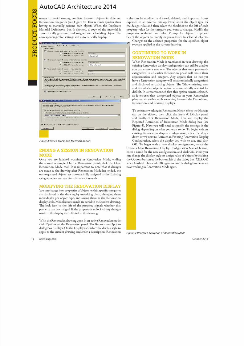
8122019 augi world 2013 10
httpslidepdfcomreaderfullaugi-world-2013-10 1352
AUGI Members Prepare for the Future of Design
Join industry experts and design visionaries for 3 intensive days of classes andconversations on this yearrsquos hottest topics ndash 3D Printing BIM Cloud ServicesPLM Reality Capture and more
AUGI Highlights at AU 2013
bull AUGI Day Join the scavenger hunt and win great prices
bull AUGI Annual meeting and Beer Bust Get informed on AUGIprograms and planshellipand end the day with a cold brew
bull AUGI Top DAUG Contest Show your cerebral prowess the grandprize winner receives a free AU 2014 pass and HP notebook
bull Come visit the Community Pavilion on the Exhibit Floor to meetyour fellow professionals from the International Communities
Register starting September 12 2013 at httpauautodeskcom
Autodesk University 2013December 3-5 2013The Venetian Hotel Las Vegas
8122019 augi world 2013 10
httpslidepdfcomreaderfullaugi-world-2013-10 1452wwwaugicom October 20
PRO
DUCT
FOCUSAutoCAD Architecture 2013
ACTIVATING A DEMOLITION PLANTe display of a demolition plan shows existing construction andthose objects categorized as demolished All new objects howeverare hidden Display settings for the demolition plan type arelocated in the options dialog box for Renovation Mode
o create a demolition plan activate Renovation Mode as
previously discussed and then select the button for DemolitionPlan on the Renovation panel of the ribbon You can now selecta Renovation Display Configuration to activate Te box next toHide All New Objects is automatically checked If you want Newobjects to show while you are working in the drawing click in thebox to deselect the item and then click OK You can also click theNew ShowHide button on the Renovation panel You are nowready to begin creating a demolition plan
Please note that yellow is automatically assigned by default todemolition objects Tis can be changed in the options dialog boxfor Renovation mode under the Layer tab
ACTIVATING A REVISION PLANA revision plan displays new and existing construction objects butall demolition objects are hidden automatically Display settingsfor the revision plan type are located in the options dialog box forRenovation mode
o create a renovation plan activate Renovation Mode as previouslydiscussed and then select the button for Revision Plan on theRenovation panel of the ribbon You can now select a Revision
Plan Display configuration to activate Te box next to HiAll Demolished Objects is automatically checked If you waDemolition objects to show while you are working in the drawinclick the box next to deselect the item and then click OK You caalso click the Demo ShowHide button on the Renovation panYou are now ready to begin creating a revision plan
MANUAL MODIFICATIONSSometimes walls of different renovation categories do not intersecorrectly so manual modifications become necessary Tis can bdone by temporarily suspending Renovation mode For exampyou may have a plan that includes walls categorized as demolitioand walls categorized as existing with wall edges that need to corrected Remember objects categorized as New do not interawith objects categorized as Demolition When you need to maka manual correction you temporarily interrupt Renovation moby freezing the walls you want to modify and then correcting thedges Tese changes are not considered part of Renovation Toption to freeze or thaw walls is only available when Renovatiomode is active
Letrsquos make this a little clearer o do a manual modification clicthe Freeze Walls button on the Renovation panel of the ribboNext select the walls in question and hit Enter Renovation mois now temporarily suspended Proceed with correcting the wedges and then click Taw Walls when finished Renovatiomode resumes
RENOVATION STYLES CATALOGTe Renovation styles catalog contains display and layassignment styles AutoCAD Architecture-based styles for objecare managed with Style Manager By default the Renovation styl
catalog is installed in ProgramDataAutodeskACA ltversiongtenuStyles If the Renovation styles catalog is renamed or movethe styles are disabled and cannot be accessed Use the RenovatiStyles Catalog Settings dialog box to specify a valid catalog
With the Renovation drawing open in an active Renovation modclick Styles Catalog from the Options drop-down menu on tRenovation panel Te Renovation Styles Catalog Settings dialbox displays Select the Import renovation styles from catalcheckbox for drawings to be populated with all Renovation stylin the specified catalog Clear the Import renovation styles frocatalog checkbox for new drawings to include standard styles onlBrowse to the location of the Renovation styles catalog you wa
to use Click OK
Melinda Heavrin is a CAD Co-ordinator amp Facility Planner forNorton Healthcare in LouisvilleKentucky She has been usingAutoCAD Architecture since re-lease 2000 Melinda can be reached
for comments and questions atmelindaheavrinnortonhealthcareorg
Figure 6 Demolition dialog box
Figure 7 Revision dialog box
8122019 augi world 2013 10
httpslidepdfcomreaderfullaugi-world-2013-10 1552October 2013 wwwaugiworldcom
Inventor 2014by Mark Flayler
F
ree Autodesk Inventorreg apps You meanlike a Bloominrsquo Onion at Outback Countme in Wait you mean Inventor apps asin applications that change how Inventor
works for me and makes me more productive OkayIrsquom still in but I also still want some fried food
In this article we will take a look at severalof the free apps available in the AutodeskInventor Exchange store for trial purchase andSubscription customer benefits
DESIGN CHECKERTe first one we will take a look at is the DesignChecker that was previously called Validus and
sold through DMSI Autodesk purchased thissoftware in a manner similar to its purchaseof the iLogic code from Logimetrix a coupleyears ago Luckily I was a user back before thisacquisition so I know the tool pretty well Tefact that the software went from costing around$3000 to being a free tool delivered exclusivelyto Subscription customers is a really nice benefitfor having an Autodesk subscription right now
Te Inventor Design Checker is a productivitysolution that gives the designer insight into the
adherence of company or customer standards for
the product being designed Live Checking gives instant feedbackto the user and ensures a high level of quality for the entiredesign process
Users can use pre-defined checks or define custom checks withiLogic scripts to perform design checking Executing the on-
10 AppExchange
Reviews
Figure 1
8122019 augi world 2013 10
httpslidepdfcomreaderfullaugi-world-2013-10 1652wwwaugicom October 20
Inventor 2014
PRO
DUCT
FOCUS
demand checking updates the design checker results and enablingthe live-checking allows users to get the real-time feedback fromthe design checker during design process Te Design CheckerResults ree Browser allows users to interactively edit the objectswith failed checks and a Design Checker Results Report shows allthe passed and failed check results and allows users to export thereport to Excel Word or pdf or print the report
Now what I really enjoy about this tool is the iProperty checks andsome of the modeling checks Te machining checks I could livewithout mostly due to the fact that most companies try not to hireusers who make such drastic mistakes in machining operationsMy favorite thus far is the unconstrained sketches check thatvalidates my design before adding it to Vault I have also usedthis as a measuring stick before hiring new engineers or bringingvendor Inventor models into my design
AUTODESK REMOTETis next app allows some really nice RDP usefor Autodesk Inventor Autodesk Remote is astandalone application for Microsoft Window7 and 8 and is compatible with all Autodeskproducts It lets you drive Autodesk softwareinstalled on your primary computer from aremote computer or iPad for fast access to nativedesign data over standard networks o use itsimply install Autodesk Remote on the PC you
want to share Install it again on the machine youwant to connect from and start your connectionNote Autodesk Remote currently works only inNorth America
Autodesk Remote also has a companion applicationfor the iPad that allows you to access your hostPC from an iPad Te iPad app is optimized forAutodesk Inventor so you can work from anywhereimproving collaboration and increasing flexibilityDownlaod the iPad app from the Apple Store
Te controls in the iPad app are pretty easy to understand bthat doesnrsquot make a high-end CAD product made for the Pinstantly translatable to a touch interface You can see wheinterface elements of Inventor have started to lean more towarthis inevitable progression though
From my usage of the iPad app on my iPad 3 I found the usagelittle sluggish and gesturing a bit picky I found the use the ES
Figure 2
Figure 3
Figure 4
Figure 5
8122019 augi world 2013 10
httpslidepdfcomreaderfullaugi-world-2013-10 1752October 2013 wwwaugiworldcom
Inventor 2014
key a mandatory function as I often initiated one navigation tooland found myself trying to start something else before finishing thetool I was in In the end I see some fantastic usage on the horizonfor this app but right now it is pretty gimmicky for my taste I dopicture myself at some point on my front porch with my tabletinstead of my computer I would look cooler to the neighborhoodkids too
Be aware you will probably have to troubleshoot the setup of thisapp a bit I had to lock and unlock my computer and restart theapp several times before I got it just right
FEATURE RECOGNITIONTe Feature Recognition application converts neutral 3D CAD
models such as SEP SA or IGES solids into full-featuredAutodesk Inventor models Feature mapping could be executedautomatically or interactively as needed to maintain design intentCurrently there is one Automatic Feature Recognition commandand eight feature recognition commands you can use
Automatic Feature Recognition attempts to recognize specificfeature types and populate the browser tree with the recognizedfeatures A dialog box displays the feature types you can recognizein the Features section with the defaults checked You can selectfeatures you want to recognize and deselect features you do notwant to recognize
When you import a file it will offer to start feature recognition Ifyou decide to do it later you will have to find your Base1 solid inyour tree and right click on it to start it again
Tis tool has been around for a long time previously only on
Autodesk Labs Personally I donrsquot like it mainly because I have toconstrain and dimension the sketches when they get recognized bythe tool If your goal is to bring in a solid and then do some minormodifications to it then you are better off using the Edit Solidtools also shown in the image above If you want Work Plane toolsalso remember to turn off the Import into Repair Environment aswell before opening the file
If you really had to go the distance and recognize features it isactually a lot quicker and generally creates a more intelligentmodeling history if you just redo it yourself in Inventor Terecognition tools only lend themselves to simple parts inmost cases
Figure 6
Figure 7
Figure 8
Figure 9
8122019 augi world 2013 10
httpslidepdfcomreaderfullaugi-world-2013-10 1852wwwaugicom October 20
Inventor 2014
PRO
DUCT
FOCUS
WORK FEATURE VISIBILITYTis product allows Inventor users to manage all work featurevisibility in a fast and easy way keeping full awareness of the involvedentities Tis app consists of six buttons on part environment andanother six on assembly environment Inside of part environmenta user can choose to enable or disable the visibility property ofplanes axes or points Inside of assembly environment a user can
also choose on which components to enable or disable the visibilityproperty of planes axes or points
I had a little trouble with this app in the assembly environmentbut that was due to some bad installation files Tis is one appreally worth the $099 How often have you been in an assemblyand not wanted to go back to the part files to turn on and offwork features I recommend ungrouping them so you access bothcommands faster
SHEET METAL FLAT EXPORTTere seems to be a plethora of these apps on the Exchange witheach of them varying in price and options In general the ideabehind these apps is to help automate the process of getting a DXF
to a machine that reads them for manufacturing in a more efficientmanner Tese programs will scan an assembly file and find thesheet metal files on which to perform their routines
Te different variations of this program range from free trialsupwards of $100 for the paid apps I started with one that gave me
a ldquoliterdquo version that would do 20 sheet metal files and I liked it much I started using the full version
FEATURE MIGRATORTe Feature Migrator tool allows Inventor users to more eascreate part features from assembly features User can migraassembly features either by selecting them in the Feature Migratbrowser or by right-clicking on one or several of them and theusing the ldquoSend to Partsrdquo commands Features can also be directmigrated from the regular Inventor model browser using thcontext menu item added by the add-in
Once the operation of migrating features is completed the FeatuMigrator displays a dialog that provides information about thresults Tis first dialog is a ldquohigh-levelrdquo report of the migrationprovides the opportunity for the user to select the action to takfor all the assembly features migrated Suppress if SucceedeSuppress always Delete if Succeeded Delete always or Nothingalso for the part features that havenrsquot been migrated correctSuppress Delete or Nothing Features created by the add-in cbe in an invalid state in the parts for a number of reasons
Te user can also see when a feature is out of date from thassembly and perform updates from the part side
Figure 10
Figure 11
Figure 12
8122019 augi world 2013 10
httpslidepdfcomreaderfullaugi-world-2013-10 1952
8122019 augi world 2013 10
httpslidepdfcomreaderfullaugi-world-2013-10 2052wwwaugicom October 20
Inventor 2014
PRO
DUCT
FOCUS
TIME STAMPime Stamp is an Autodesk Inventor add-in that provides bull A low-cost simple-to-use tool that adds plot time information
to your printsbull A plot stamp that does not dirty the Inventor drawing
documentbull
A simple dockable user interface that keeps out of the way
Te ime Stamp editor lets you size position and orient thestamp relative to the adjacent sheet edges You can include datetime and current user information in the stamp Te time stamponly appears on the plot it does not alter the Inventor drawing
What I really like about this app even though it costs $500 perlicense is that you can find the price yourself and buy it It doeseverything it says it does and it provides an easy-to-use interfacewith an icon that changes based on whether the tool is on or offIf you want even more control over your plot stamping there is amore professional version offered by this company on their websitefor about $4000 a license which will allow more reporting fieldsand more control on the look and location of the stamp
SIMPLE SHEET SETTINGSSimple Sheet Settings combines the existing sheet settings withsome new tools such as changing the title block and also the abilityto make changes to all sheets in a document at once
Instead of first deleting the existing title block from a sheetexpanding the title block folder and inserting the desired titleblock then opening another window to change the sheet size andorientation just click the ldquoSettingsrdquo button located on the Sheetspanel in the Placed Views tab (right next to ldquoNew Sheetrdquo) andhave access to all those options in one location
When the Simple Sheet Settings window is loaded it gathers all the existing title block names and puts them into one drop-dowmenu o change the title block on the current sheet simply selethe desired title block from the drop-down menu and click OKTere is also the ability to change the title block sheet size ansheet orientation to all sheets at one time
Tis is a great little app that saves clicks and only costs a dollaQuite useful and no real setup involved
INTERACTIVE TUTORIALTe Create an Interactive utorial app provides instructions fcreating your own interactive Inventor tutorial Te Guide alincludes how to customize the Welcome Screen to display yointeractive tutorial and add to the ribbon
Tis one definitely falls under the ldquotoo much time on your handuser or CAD admin After reading through the guide on how create the interactive tutorials you find yourself asking the questioldquoWhy donrsquot I just save videos of the process we use in a companserver locationrdquo And that is when you uninstall this app as yohave realized that while it sounded good to you at first there abetter ways to accomplish the goal of company-specific tutoria
and process documentation
Figure 16
Figure 17
8122019 augi world 2013 10
httpslidepdfcomreaderfullaugi-world-2013-10 2152October 2013 wwwaugiworldcom
Inventor 2014
Te tools actually rely on too much externally controlled softwaresuch as Camtasia and other plug-ins and third-party apps to makeit work correctly Save your time and just use Camtasia from
echsmith to do your bidding
KEEPING UP TO DATEWith all these apps it is easy to understand how a user could getbehind on the updates to so many tools With that in mind theExchange Manager found on the ools tab in Inventor will keeptrack of that for you and offer assistance not only in updating butalso uninstalling and specialized help for each app
As a reminder with regard to third-party apps if you startexperiencing undesired effects in Inventor start turning add-ins
off one by one until you isolate which one is giving you fits Properreporting back on the app to the developers makes everyonehappier when the issue gets resolved Tus far I havenrsquot had nearas many issues as I thought I would have
ANY MANY MOREWith 80+ apps currently in the store and about 60 of them ready
for 2014 at the time of this article you should take some time andlook through what is available Tere are apps which are very nicheto the user base as well as those that have you scratching your headover why they are not already part of the core software Below aresome I would write about if I had more room in the article andora fatter PayPal walletbull BOM oolsbull EDM Expressbull Sketch Symbol Librarybull SolidWorks iProperty Importbull Quick Viewsbull 3D Pipebull Point Linkerbull Kwikools
Mark Flayler is an application engi-neer with IMAGINi echnologiesspecializing in manufacturing environ-ments He has implemented Autodeskmanufacturing products within severalindustries including the blowinjectionmolding automotive and custom ma-chinery markets When not providingtraining support and implementationhe writes the IMAGINi Manufac-turing Blog and takes an active role inthe manufacturing community Markis an AC certified instructor and isPSE and AC certified in AutoCADAutoCAD Mechanical AutoCADElectrical Autodesk Data Manage-ment and Autodesk Inventor
Figure 18
Figure 19
8122019 augi world 2013 10
httpslidepdfcomreaderfullaugi-world-2013-10 2252wwwaugicom October 20
SPECIALFEATUREAUGI Forums by Melanie Perr
The AUGI Forums are as always a busyplace Ask a question and you mightsee half a dozen varied methods andworkarounds posted in a single thread If
you have not had any questions yourself I would stilllike to encourage you to pop into the Forums and see
if there are any problems you could solve especially if you use one
of the less adopted products Tere will always be many helpinghands in the AutoCAD and Revit Forums but what about themechanical products or design visualization or structural detailingForums Peek in and see if you can share your experiences andwisdom with the community
I confess that I only scoured the English-speaking Forums forcontent for this article but please keep in mind that there areAUGI Forums available in 12 other languages so users have theoption of asking for support in their native tongue
AUTOCAD ndash SYSTEM VARIABLE
DISCUSSIONhttpbitly15M1hB9
Tis topic started out when a user couldnrsquot delete Te solution wasultimately the PICKFIRS variable but the discussion evolved tosafeguarding other variables automatically just to protect against aloss of settings in the event of a crash User Coloradomrg offeredthe safeguard shown in figure 1
Norton_cad also suggestsDIMLFAC EXPER andBLIPMODE be addedto the list
REVIT ndash
UNDERLAY
BEHAVIOR
EXPLAINEDhttpbitly15M1iFd
Mschroeder opened thediscussion with If you haveever wondered why some wallsdonrsquot show up in underlays or
show up inconsistently from floor to floor or why roofs and vieranges affect their behavior then read on
First rule of underlays Underlay view extent properties (cut rangdepth) are not user modifiable and not coupled to any othviewrsquos properties
Itrsquos also been mentioned ldquoIf objects are visible in the view ranof your current view AND in the view range of your Underlathey are automatically hidden in your underlay so there isnrsquotdouble instancerdquo
Users twiceroadsfool and dbaldacchino helped clarify the effecby posting sample models and pertinent data from the AutodeKnowledgebase and Autodesk Support Visibility View RangDetail Level and Cut Planes are all touched on in this discussioNeed clarity on how to make the most of Underlays Check inthis thread on the Forums
LISP ndash MAKING A DIALOG BOX RETAIN
ITS SELECTIONShttpbitly15JzMCc
Te LISP Forum always has such fascinating topics it is hato decide which to highlight From locking OSNAP options setting Explode options along with troubleshooting of existincode But the discussion surrounding the tutorials and metho
to retain selectioin a dialog box wvaried and lively so had to check it ou r e a v e s 0 4 4 1 3 2 1
even posted a sampdcl file when he wfinished
String Theory
8122019 augi world 2013 10
httpslidepdfcomreaderfullaugi-world-2013-10 2352October 2013 wwwaugiworldcom
AUGI Forums
AUTOCAD ELECTRICAL ndash LINES BEING
LABELED AS WIREShttpbitly1ew9p9D
Dinochrome says that one of his coworkers has reported aproblem with regular AutoCAD lines being labeled as wires
Crosswire35 advises ry checking your wire type edit dialogbox and make sure the ldquomake all lines valid wiresrdquo checkbox is unchecked
And IMCO goes on to say Using the vanilla line command inACADE will still place that line on a wire layer Change your linesto layer 0 and ACADE will not give them a wire number
AUTOCAD STRUCTURAL DETAILING ndash
TUTORIALShttpbitly17kW7cc
Te consensus is that this product is a little confusing to figure outand that most of the tutorials out there are older Most productshave a few videos floating around on Youube but this one doesnot seem to have too many yet
Jpo82 chimes in with I guess only tutorials forthis software are those found at Autodesk websiteTey are for versions 2010 and 2011 but still validhttpusaautodeskcomadskservlet12ampid=13111928 Irsquom not sure but sometimes I feel that the only new feature inASD 2013 is that itrsquos more stable than previous releases
Lucis29 goes on to say Also you might check some movieshttpwwwrobotofficecomasd but they are very old
Spenner then linked to his reporting of the Service Pack andissues it addressed hoping that it addressed some of the issuesthat came up in this discussion
NAVISWORKS ndash IMPROVE ANIMATION
EXPORT QUALITYhttpbitly1fQLoIv
Different methods are discussed from exporting individual imageframes to exporting a video (and how long) but I will leave youwith the following list from Revit For Breakfast
Here are the secrets to movies in Navisworks1 Donrsquot use materials ndash you make your render time much longer2 Use the PNG export option 15fps3 Make your video export twice as long as you need Ten speed it
up for a faux 30fps Tis is faster4 Look up the Navisworks blog by Lee Mullin and Paul Walker
about gooch and phong Tere is your faux render setting5 If you have NW 2012 you wonrsquot have gooch or phong but you
will have better export options 2013 has gooch and Phong butfewer export options
6 Te flickering occurs when multiple shapes overlap If you care
delete them in your export model Sometimes flickering occurs
in the generation of your frames on the PNG export You mayhave a frame that is ldquooffrdquo
7 Set your anti-aliasing to 4x or better on the png export8 Check out my old post httpforumsaugicomshowthread
php132209-Animation-Resolutionampp=1138298ampviewfull=1post1138298
CAD MANAGEMENT ndash NETWORK DRIVE
CHANGED BY IT WITHOUT WARNINGhttpbitly18J4k9c
Blackbox advises edinsmore595165 straight off to utilize theReference Manager program that comes with AutoCAD inorder to reconnect all of the external reference paths that werebroken when the I department upgraded their archaic serversHe further points out that moving from hard pathing to relativepathing would make things easier in the future
Feargt offers another twist Another option which would workon a need only basis when you open the specific drawing Change
XREF and Image paths in drawing to Network path throughscript on a need only basis Basically this will only change pathsPlace this line in a acaddoclsp file(command ldquoscriptrdquo ldquoyourserver and pathXREFREDIRECscrrdquo)and the following in a script fileREDIRB enter name of path to be replacedP enter new path
Tere was also a debate in this thread about obstacles and benefitsof user-managed and I-managed drive mapping
Melanie Perry is a Facilites-Manage-ment Coordinator and echnical Edi-tor in St Louis MO She is the AUGISalary Survey Manager and is curring-ly serving as an Officer on the Board ofDirectors Melanie can be reached atmistressofthedorknessgmailcomor found on witter asMistresDorkness
OTHER HOT TOPICSHave you found a Forum solution so mind-bogglinglyuseful that you leapt out of your chair with a whoopingcheer (or were at least tempted to) Please let me know Asingle person cannot read every post in our bustling AUGIForums so if you would like to see a thread highlighted ina future edition of String Teory feel free to let me knowSend me Wanderer a PM in the Forums or send an emailto MelaniePerryaugicom
See you on the Forums
8122019 augi world 2013 10
httpslidepdfcomreaderfullaugi-world-2013-10 2452wwwaugicom October 20
Revit Architecture 2014
PRO
DUCT
FOCUS
by Martijn de Rie
Myth Buster
Revit amp IFCPart 3
Irsquove given a lot of thought as to how this trilogyof articles should end At first I thought Irsquoduse the Coordination View 20 EXPRESS-GWallPaper for IFC2x3 (httpwwwmdr-
adviesnlwp-contentuploadsCoordinationView_V2-0_WallPaper_IFC2X3_Version-1pdf ) as a stepping stoneto give an ldquoIFC for Dummiesrdquo type of solution But that turnedout to be quite lengthy and rather boring But the link is includedabove for obvious reasonsmdashitrsquos useful
So I went back a little and asked myself ldquoWhy IFCrdquo And with thatquestion the inevitable follow-up immediately appeared ldquoWhynot IFCrdquo I realized that in the previous articles I failed to explainwhy in my humble opinion we should care about this somewhatcrooked badly implemented severe headache-inducing formatTerefore instead of explaining the fundamental technicalities ofIFC that can be explored in other places this final installment willexplore the Why versus Why Not IFC discussion and begin withthe latter
WHY NOT IFCWhen everybody uses Autodeskreg RevitregWell in this case itrsquos a no-brainer Share your Revit files Period
Loss of dataTis is an easier way to share data instead of hacking your wthrough IFC and praying your stuff doesnrsquot get lost in the proce
Even when you manage to export your geometry through IFtherersquos always loss of data
Loss of intelligence during importEven if you only need to send over geometry not data importithat into Revit makes it utterly useless All constraints are locomponent parametrics are gone and so on
Availability of bidirectional linksWhen not everyone uses Revit on a given project (which is quoften when yoursquore not located in the US) why not simply ua bidirectional linking between proprietary software standardTis can be easier and better to control
8122019 augi world 2013 10
httpslidepdfcomreaderfullaugi-world-2013-10 2552October 2013 wwwaugiworldcom
Revit Architecture 2014
WHY IFCWhich may be asked as why would you want to use IFC Or moreaccurately why would you want that option available
Consider what Sir Arthur Conan Doyle wrote ldquoOnce you eliminatethe impossible whatever remains no matter how improbablemust be the truthrdquo
Letrsquos put that to the test shall we
When everybody uses RevitOkay simple math Autodesk has around 7000 employees Teworld has about 72 billion people What are the chances someonenot working for Autodesk has a brilliant idea and creates thesoftware you need tomorrow Tere will always be better solutionsTey might not be viable for you overall but therersquos no reason toshut down access to them Revit is a wonderful generic tool forwhich I see a brilliant future with all kinds of additions for specificniche-markets like AutoCAD has
What about today DDS is MEP-engineering software that cando energy calculations (not simulations) inside your modelRhino lets you model things on the fly that could (arguably)take ages in Revitmdashif you ever get them done ekla lays wasteto the Revit structural rebar functionality any day of the weekwithout breaking a sweat Solibri is a wonderful solution for clashdetection and most importantly rule-based model checking andreportingmdashsomething Revit (or Navisworks) doesnrsquot do
Should I go on
Only problem for all this magnificent software Itrsquos either based onthe IFC format or requires model exchange through IFC
Te fact of the matter is there will always be better softwareAny one may be the software for you but that doesnrsquot mean yourpartners associates etc need to have the choice to use it forcedupon them
Loss of dataOn July 1 2013 there was an extra release for Autodesk softwareTe Sourceforge Open Source IFC Exporter released a new versionthat incorporated the option to map custom Revit parameters(shared or non-shared family or project even calculated values) totheir IFC counterparts
On September 28 2013 I had the honor of showing the secondstep in a complete and controllable data export from Revit
During my RC Europe class I showed the new option to create acustom IFC Property Set and map any given Revit parameter intoIFC fully customizable
IFC does not automatically lead to loss of data Tat idea is simplynot true Incomplete implementation in Revit does lead to loss ofdata As of now you are able to put any piece of data into an IFCeven calculated values And we didnrsquot change the IFC format We
just improved implementation in Revit
Loss of intelligence during importldquoJust because something hasnrsquot happened yet doesnrsquot meanitrsquos impossiblerdquo
I donrsquot know who originally had this insight and I doubt it to bethe movie line I remember but it is true
In the same RC Europe class I showed a native Revit familybeing exported to IFC altered and re-importedmdashwhile keepingall parametric constraints and even adjusting to the alterationsmade directly in the IFC file It is possible but not with thecurrent importer
Availability of bidirectional linksIrsquove been using Revit for almost 10 years now For 4-5 years I didnrsquotknow about IFC at all Before a year ago this was my strongestargument against IFC Why would you need a generic ldquolanguagerdquowith all its limitations (of which there are) weaker implementationand use of parametric capabilities (because it has) and lag-times indevelopment (by nature)
IFC will never be able to do what native software does simplybecause itrsquos responsive in nature Development budgets are afraction of what Autodesk rimble or Nemetschek get to spendon their software
So why not keep it simple and use a bidirectional link Revit has itwith a lot of other Autodesk software and third-party applications
But how long have we waited for them And are they even trulybidirectional Do they exactly do what you want them to do In myhumble opinion the answer to these questions is not very inspiringEven bidirectional links tend to have major limitations and severe
constraints in flexibility And most important Te link itself isalso propriety software No way of adjusting it to your needs
WHAT IF MORE PEOPLE STOPPED
TALKING ABOUT IT AND JUST GOT
INVOLVEDTe improbableFirst off itrsquos a matter of simple logic As Sir Arthur suggested ifwe can successfully check off all likely options to NO want touse IFC doesnrsquot that mean the improbable is true Tat IFC is infact a valuable tool in our toolkit and we should be able to use it
when necessary
Mind you Irsquom not saying you should use IFC If yoursquore on a Revit-only project it would be insane Just send and receive RVs Tefact is this will only be viable for limited parts of the buildinglifecycle If yoursquore lucky the entire design team is on Revit Butmanufacturers have other software facility managers too
As for the design team what if the best structural engineer is not[on Revit] or the MEP guy that has loads of experience in similarprojects Would you settle for second-best just because someoneuses the same brand of tools you do I wouldnrsquot
8122019 augi world 2013 10
httpslidepdfcomreaderfullaugi-world-2013-10 2652wwwaugicom October 20
PRO
DUCT
FOCUS
Revit Architecture 2013
Open AccessWhich brings us to the biggest advantage of IFC (or any open
format) itrsquos open Which means itrsquos adjustable to your needs Nowdonrsquot go ldquothatrsquos too difficult expensiverdquo Tatrsquos bullocks
Te first external enhancement to the Open Source Exporter wascreated by om Pesman a self-employed API specialist
Parametric IFCImplemented by Jon Mirtschin also self-employed IFCparametrics is available Agreed Jon is a well-known IFC guru butstill the point holds
Custom property sets and parametersWim as owner of a small MEP engineering firm hasadded functionalities toward this end and hersquos not even a trueAPI specialist
All these developments were done for free by altruistic volunteerefforts as part of the creation of the Dutch Revit Standards Andof course with the invaluable help of the Autodesk Open SourceIFC Exporter team Angel Velez in particular
But what if these guys actually got paid What if this projectwasnrsquot a Saturday night side-job What if more people stoppedtalking about it and just got involvedmdasheither by themselves or byleveraging experts to get what is needed Te entire IFC format is
Open Source the source code is out there which basically meansyou can do whatever you want and create whatever you needmdasheven on a project-by-project basis
BIM ITrsquoS THE ldquoIrdquo THAT MATTERSIn my humble opinion the entire debate on BIM is focusing on thewrong part of the acronym I donrsquot care if ldquoBuildingrdquo is a noun ora verb Nor do I care whether itrsquos ldquoModelrdquo or ldquoModelingrdquo nor am Icommenting on whether one should say ldquoBIM Modelrdquo
Itrsquos the ldquoIrdquo that matters If wersquore collaborating the Informationis most all I care about I just want your datamdashin the leanest
smartest and most effective way possible
A Revit model will do conversely a lot of times A Revit model w
give me heaps of data I donrsquot want geometry I donrsquot care about ana file format I canrsquot use Now we can all keep on being really anabout it or we can simply use the tools available to us one of thebeing IFC
A FINAL NOTEAs stated at the beginning of the article I really enjoyed writinthis series and for now this is the last of the series But if yoursquointerested in more tips and tricks on IFC let me know I might able to persuade the guys at AUGI to let me write about it againLord knows there is still a lot to talk about regarding IFC
Martijn de Riet is a self-employedBIM Consultant from the Nether-lands working with Revit since version51 Martijn has a bachelor degree inBuilding Science After his studieshe started his own engineering firmworking for contractors architects and
private clients Starting in 2007 hiscompany transformed into a full-timeBIM consultancy service At the mo-ment Martijnrsquos clients vary from mid-sized architectural firms to the largest
dutch General Contracter and MEPEngineering firms with a focus onspecific corporate solutions design andimplementations of Revit and BIMworkflows Martijn is a member ofthe Dutch Revit User Group and cur-rently working on creating a Masteremplate and Component LibraryHe provides lectures for companiestechnical universities seminars etc ona regular basis
Itrsquos the ldquoIrdquo that matters If wersquore collaborating the Information is most all I care about I justwant your datamdashin the leanest smartest and
most effective way possible
8122019 augi world 2013 10
httpslidepdfcomreaderfullaugi-world-2013-10 2752
wwwxicomputercom
8122019 augi world 2013 10
httpslidepdfcomreaderfullaugi-world-2013-10 2852wwwaugicom October 20
3ds Max 2014
PRO
DUCT
FOCUS
by Chris Murra
SUMMARY WHATrsquoS
CUSTOMIZABLE IN MAX
(HIGH LEVEL)When it comes to the customizability of Autodesk 3ds Maxregitrsquos no secret that it can morph itself into whatever you want theprogram to become
Whether yoursquore a modeler animator lighter rigger generalist ortechnical artist 3ds Max can become your own personalized toolbox that is an extension of your own hand in your daily workYou can now combine different command types (such as creatingobjects and object modifiers) into a single menu reducing themouse travel and improving efficiency
In this article wersquore going to take a closer look at one specificaspect of customization with 3ds Max the new enhanced UI Aspart of this article besides taking a deep dive into the operationof this feature I will also be showing how I created the ldquoMographrdquo
tools UI that includes custom buttons and icons At the end this article I will also provide a link to this UI so you can use customize it yourself or share it with others
ENHANCED UI SUMMARYWhat is the Enhanced UI
Te Enhanced UI is a new graphical user interface system thdoes two main things
1) It provides a refreshed 3ds Max user interface with updattool categories and new clusters of pre-existing tools in groupinthat are more akin to their intended purpose as opposed to somtechnical requirement for menu placement
2) It provides a way to allow you the end user to customize thmenu system in almost any way you choose Te drop-down menare ldquotear-ablerdquo (not to be confused with ldquoterriblerdquohellip but I digresand the resulting configurations are savable either by scene or
3ds MaxEssentialsCustomizing
the UI
8122019 augi world 2013 10
httpslidepdfcomreaderfullaugi-world-2013-10 2952October 2013 wwwaugiworldcom
3ds Max 2014
a preset Tey are also distributable and deployable so they can beshared with others
Where is the Enhanced UITe Enhanced UI can be found in the upper left hand corner of themain UI at the very top of the screen Tere is a drop-down menuthat says ldquoWorkspace Defaultrdquo Tis default is the same baselineUI that ships with all 3ds Max installs (Figure 1)
Within the drop-down you can find the ldquoDefault with EnhancedMenusrdquo Tis is the alternative default menu system that youcan use on its own or use as a starting point to create your owncustomized menus
BASIC DEFAULT CUSTOMIZATIONEnhanced UI Customization BasicsNow that wersquove enabled the Enhanced UI how can we change it
SOP Before you begin mucking around with the UI Itrsquos importantto understand what I call the ldquosave-logicrdquo as it pertains to custom UIs
Te UI Save LogicIf you plan on saving this UI for future use there is a specificmethod you must follow to properly save the UI you want and notwreck the default Enhanced UI
Te Save Logic is as follows Itrsquos simple but important
Step 1 urn on Enhanced Default UI (Figure 3)
Step 2 Click ldquoSave as New Workspacerdquo FIRS At this point youwill be prompted for a new name (Figure 4)
Step 3 Edit and change the UI at will
NOE All future edits are ldquoautomatically rememberedrdquo as you go (Iintentionally did not use the word ldquosaverdquo)
Step 4 Te ldquosave as default staterdquo button is important When wehave completed the customization process we then choose thisbutton to ldquolockrdquo in the changes Tis is different than Saving a UIwith a custom name
HO IP ldquoBut this methodology seems backwardrdquo
I can see how yoursquod say that but remember that any changes you make
to any enhanced UI are automatically ldquorememberedrdquo If you create acustom UI then while working you make some temporary changeswhen doing something specific those little changes are automaticallyremembered If you want to return to the default state [of yourcustomized UI] you select ldquoReset to default staterdquo Tis does NObring back the default Max UI rather it brings back the customizedUI you created in ldquolockedrdquo in Step 4
Okay now that you have the save logic down letrsquos begin customizing
1) If you havenrsquot done so already turn on the Default Enhanced UI
2) Go to ldquoManage workspacesrdquo from the drop-down and in the
Figure 1 Workspaces are in the Workspace drop-down menu
Figure 2 Default UI (left) and the Default Enhanced UI (right)
Figure 4 Saving the New UI Workspace
Figure 3 Turning on the Enhanced Default UI
8122019 augi world 2013 10
httpslidepdfcomreaderfullaugi-world-2013-10 3052wwwaugicom October 20
3ds Max 2014
PRO
DUCT
FOCUS
Manage workspaces dialog choose ldquoSave as new Workspacerdquo Giveit a specific name
3) Begin making your desired changes
Since a custom UI is specific to any one individual letrsquos take a lookat what types of customizations can be made
Simple ChangesOne of the simplest things to do is peel off any commandgroup (see Figure 5) Just click the group title bar and drag Tecommand group becomes a floating dialog box Now just becauseyoursquove peeled it off does not mean that yoursquove removed it fromthe drop-down menu Te ldquooriginalrdquo command group remains inthe drop-down You can just close the floating dialog when yoursquoredone with it
Probably the simplest thing you can do is reorganize the menusIn each drop-down menu appears a group of commands You maynotice that some command groups are icons and some are words(Figure 6) o change the appearance of the commands there is asmall icon in the upper right corner of each group of commands(Figure 7)
Te next change is alreally simple Is tcommand group op(expanded) or clos(rolled up) Just clion the plus or minsign in the upper le
corner to set this stafor the next time yolaunch 3ds Max (Figu8) Remember thesettings are saved as yogo so whether it is opor closed is your choicbut the state the menis in when you cloMax is the one that remembered the netime Max opens
What about Saving tDefault state More othis later
Once you have floating menu yocan combine differecommand groups dragging any othcommand group to aother floating dial
that yoursquove created Tis makes for easy creation of custom dialo
based on specific tasks Figure 9 shows a command group fcharacter animationFigure 5 A floating menu that has been torn off the drop-downmenu
Figure 6 The different display states of the menus
Figure 7 Changing menu layouts
Figure 8 Rollouts
8122019 augi world 2013 10
httpslidepdfcomreaderfullaugi-world-2013-10 3152October 2013 wwwaugiworldcom
3ds Max 2014
ADVANCED CUSTOMIZATION
What about completely custom interfaces Herersquos how we do thatwith the Enhanced UI menu system
Te following is the high-level overview of the process Wersquoll thenunpack each step in more detail
If you havenrsquot read the section on Basic default customizationplease do so before continuing Before starting this phase ofcreating your new UI you should have saved your new UI stateTat process is explained in the previous section
1) Create a main drop-down menu (like ldquoMy oolsrdquo)
2) Create a tools category menu into which you will place yourtools (a submenu such as ldquoModeling oolsrdquo or ldquoAnimation oolsrdquo)Drop-downs can have more than one subcategory
3) Add commands to various submenus
4) Clean up the UI by creating custom names adding separatorsor creating custom icons
First letrsquos create a new menu for the menu bar Tis is done easilyfrom the CustomizegtCustomize [Rollout]gtCustomize UserInterface dialog box
Steps for Creating a Drop-Down Menu1) Create a New Menu and give it a name (see Figure 10)
2) Locate your new menu in the Menus window It will be listedalphabetically (Figure 11)
Figure 9 Multiple command groups in one menu
Figure 10 ndash Creating a new drop down menu
Figure 11 Location of new menu
8122019 augi world 2013 10
httpslidepdfcomreaderfullaugi-world-2013-10 3252wwwaugicom October 20
3ds Max 2014
PRO
DUCT
FOCUS
3) Drag your newly created menu category over to the column onthe right Tis will add your new drop-down menu to the interfaceimmediately and you can begin populating it with menu items (seeFigure 12)
UI DESIGN IP Te actual menu name and display name can bedifferent I used a custom menu name behind the scenes so I couldeasily differentiate my menus from the ones created by default or other
tool companies After you create a menu and add it to the right column you can right-click on it and change its display name (see Figure 13)
Next letrsquos create a command group1) Just like in Step 1 from the previous section create a new men
2) Tis time before you drag it to the right column click thplus sign next to your drop-down menu item to expand it Tedrag the new item to the right column dropping it ldquounderrdquo thmenu name
3) Drag any commands from the Commands window on the leto the submenu on the right (see Figure 15)
Herersquos an example from my Mograph ools workspace thshows how a completed menu looks once it is created (Figu16) In the following figure you see both the menu as it appeain the Customize UI dialog and the actual menu (which has bepeeled off)
Notice that some of the commands on the menu are greyed ouTatrsquos because this new menu combines both ldquoObject creatcommands and ldquoObject Modify Commandsrdquo in one menTey will remain grey until you create an object on which thwill be used
Figure 12 Adding the new menu to the UI
Figure 14 Creating a command group
Figure 15 Dragging commands onto the menu
Figure 13 Custom menu names
8122019 augi world 2013 10
httpslidepdfcomreaderfullaugi-world-2013-10 3352October 2013 wwwaugiworldcom
3ds Max 2014
Adding SeparatorsSeparating commands is easy and is recommended to help you oryour intended user make sense of the how the tools are arranged inthe menu Creating a separator is as easy as dragging one over theright column just like a menu or command
HO IP ldquoWhy do I need to create another menu Why canrsquot I addtools right to my menurdquo
Te main reason is that adding a submenu gives you the ability to tearoff the submenu If it werenrsquot in a submenu it wouldnrsquot be tear-ableSo itrsquos really a ldquobest practicesrdquo kind of thing But even if you try to notadd the submenu it will happen automatically Itrsquos important to do it
explicitly so you are aware of what submenus are in the menu and that you are the one in control of what command is going where
CUSTOM ICONSNo custom UI is complete without a custom set of iconsAdditionally not all commands in 3ds Max have their own iconyet But itrsquos important to realize that regardless of how you set up
your UI yoursquore still working within the framework of an existingapplication and there are boundaries to what you can edit andcreate Icons have specific requirements both in their creation(size) location and file name that must be adhered to in order forthem to work properly
SizeformatTe size of icon is pretty simple It must be 32x32 pixels andPNG format
LocationTe location is very specific New icons must be added to thislocation
CProgram FilesAutodesk3ds Max 2014UI_lnResourcesDarkIconsMain
Te new icons I created for the Mograph UI are shown inFigure 17)
Icon File NameIf yoursquore still with me at this point we are now getting into thenether regions of customizing a UI Tis is where things get a littletricky but itrsquos really not too bad File names are specific and aregenerated by the application (3ds Max)
So letrsquos begin First identify the command for which you want aniconmdashusually itrsquos one that doesnrsquot already have an icon But if itdoes and yoursquore changing it MAKE A BACK UP of the originalicon PNG file Tis is because as previously stated you donrsquot havecontrol over the file name Tat means if yoursquore creating your ownicon you need to overwrite the existing one and use its name foryour new icon So back up any original icons
Figure 16 The completed menu
Figure 17 ndash The created icons
8122019 augi world 2013 10
httpslidepdfcomreaderfullaugi-world-2013-10 3452wwwaugicom October 20
3ds Max 2014
PRO
DUCT
FOCUS
It really doesnrsquot matter whether you make the icon first or not ofind the name you need to use you need to navigate as follows
NOE Yoursquore about to edit the ribbon Tere is no need to save thesechanges as we are merely extracting information from it But if yoursquoredoing a lot of custom icon work you may want to save this change to theribbon so you can come back and continue your work in later sessionswithout have to recreate this every time just to get the proper file nameSaving this ribbon is not related to saving your default state of yourUI When yoursquore done creating all your UI icons you can just delete
whatever changes you make to the ribbon
1) Open the ldquoCustomize Ribbonrdquo dialog box
2) Create a new ldquotabrdquo by dragging it onto the ldquoExisting Ucolumn in the middle (see Figure 18)
3) Using the same drag method add a new ldquopanelrdquo to ttemp tab (Figure 19)
4) Now you can get the information you need Find tcommand for which you are creating an icon and dragto the panel
5) Locate the ldquoinfordquo portion of the ldquoPreview Windocolumn At the bottom of the column is the file namneeded to have the icon used properly by the applicati(Figure 20)
CONCLUSIONSo now you know how to create a custom UI scheme f3ds Max 2014 and up By using the Enhanced UI me
system itrsquos really easy to generate a multitude of workspathat allow Max to work the way you want to work
Te example used in this article was the ldquoMographrdquo UI thI created for NAB 2013 If you would like to downloand install it you can get it from my ldquoPinning the Stacblog on the Area herehttpareaautodeskcomblogschrismurray
Enjoy
Chris Murray works for Autodesk
Media amp Entertainment He istrained as an animator (3D variety)but considers himself a creative tech-nologist His daily role is a technicalldquoevangelistrdquo for Autodesk creating marketing deliverables for 3ds Max Heis the author of Mastering 3D StudioMax He has a Masters in Fine Arts(MFA) in Computer Animation fromMiami International University of Artand Design Follow him on witterchrismmurray
Figure 18 Creating a tab on the ribbon
Figure 19 Adding a panel to the tab
Figure 20 Finding the required file name
8122019 augi world 2013 10
httpslidepdfcomreaderfullaugi-world-2013-10 3552
AUGIMembersReach Higherwith ExpandedBenefitsAUGI is introducing three new Membership levelsthat will bring you more benefits than ever beforeEach level will bring you more content and expertiseto share with fellow members plus provide anexpanded more interactive website publicationaccess and much more
MEMBERMEMBER MEMBER
Basic members haveaccess tobull Forums
bullHotNews (last 12 months)
bull AUGIWorld (last 12 months)
DUES Free
Premier members haveaccess tobull Forums
bullHotNews (last 24 months)
bull AUGIWorld (last 24 months)
DUES $25
Professional members haveaccess tobull Forums
bullHotNews (full access)
bull AUGIWorld (full access and in print)
bull ADN 2013 Standard Membership Offer
DUES $100
Are you ready to upgrade yourself and your membership
Access additional benefits and upgrade at wwwaugicom
8122019 augi world 2013 10
httpslidepdfcomreaderfullaugi-world-2013-10 3652wwwaugicom October 20
AutoCAD MEP 2013
PRO
DUCT
FOCUS
by Vladimir Triantafillid
BIM IsWhatrsquos
Driving theIndustry
For the past decade many would arguethat building information modeling(BIM) has metastasized aggressivelythroughout the AEC industry but what
does BIM really mean More importantly whatdoes it do for us and for our industry Ask someone who hasbeen in this industry for more than 25 years or those nearingretirement and yoursquoll find that less than half see its value muchless care to make the effort with its implementation hesequestions mean something different for those who have beenin the industry the past 10-15 years Recent college graduates
however with their tech-savvy capacity and high expectationare eager to implement anything that resembles cutting-edgflashy technology ypical ly they are the ones most receptivenot adamant about putting their talents to use through BIM
I recently gave a BIM presentation with an emphasis on mchanical systems to the summer interns and new hires our companymdashall were non-BIM users except for onemdashbmy presentation did little justice to BIM Half of my audence had found a cure for their insomnia when they realizthis wasnrsquot the latest edition of ldquoCall of Dutyrdquo hat was n
8122019 augi world 2013 10
httpslidepdfcomreaderfullaugi-world-2013-10 3752October 2013 wwwaugiworldcom
AutoCAD MEP 2013
reflection on BIM by any measure Simply put I fell shortof connecting with a potentially captive audience eager toknow what really makes BIM intriguing or how it wouldgive them an edge in the industry I didnrsquot think to look pastpresenting the facts of its processes and benefits o simplyhave stated that proficiency in any of its many facets willpromote a lucrative career would give those still awake theimpetus to jump ship In hindsight the first step I shouldhave taken to begin this presentation was to ask what theywanted to get out of BIM
If you think itrsquos hard conveying the value and splendor ofBIM to receptive and impressionable young minds try toconvince the weathered veterans dead-set in their ldquooldtricksrdquo For every experienced veteran who has converted toBIM there are two ldquoold dogsrdquo that canrsquot shake ldquothe good olrsquodays when we used vellum and light tablesrdquo Guess whatmdashanincreasing amount of naysayers are starting to come aroundincluding those who say theyrsquove been burned by BIM in thepast hey are seeing the simple solutions BIM presents and
how these solutions translate into cost savings More andmore of those who had formerly questioned BIMrsquos utility areconvinced when installation efficiencies are not only real-ized but quantified
Another factor in the evolution of BIM is its tendency toexpand faster than the pace of its general population of us-ers hose of us proud to be catching up to what we think iscutting edge quickly realize it was just another false sense ofaccomplishment as BIMrsquos web continues to grow exponen-tially he solution is rather simple Focus on what you canhandle and always have the presence of mind and sense ofcaution to avoid being overwhelmed by the wake of BIMrsquos
progress herersquos plenty of money to be made and countlessfacets to explore as long we have the following mentality Welive in the information age and those wi lling to share knowl-edge will reap the rewards of communal synergy
On the opposite end of the spectrum you might find ourindustryrsquos opportunists In a hurried frenzy to claim theirspot in the intellectual property queue these opportunistsget carried away with pioneering what they assume is the lat-est improvements to BIM Instead of stopping to absorb anddevelop the benefits of 4D 5D 6D and so on the pioneersare spreading these ldquoDsrdquo thin with abandon further expand-
ing the gap between quality and quantity None of this i s tosay that wersquore heading in the wrong direction On the con-trary letrsquos call it more of a positive economic problemmdashthedemand for BIM expertise and development outweighs thesupply of available users
Fortunately as collegiate curricula catch on to this industrytrend the point of equilibrium will soon follow For as longas I can remember respective companiesrsquo 2D CAD depart-ments have been a significant source as the breeding groundfor potential BIM users While this route hasnrsquot changedregarding the career path of a draftsperson the source poolhas expanded to include architects engineers and construc-
tion managers just to name a few Itrsquos even hard not to noticeits stark demand when BIM and Revit courses are being in-creasingly offered at local community colleges I knew thenthat you didnrsquot necessarily need an undergraduate degreeback when I got my foot in the door of this industry hisprobably wonrsquot hold true in the coming years Still the privi-leged few who are already a part of this industry subset canrely on their experience in this fast-paced market to con-tinue to propel their careers forward ever faster All thesefew need to do is grab onto a small piece of BIMrsquos wing andhang on tight for the ride he fresh-out-of-college e ntrantsmight have a harder time grabbing onto this wing thatrsquos al-ready in motion
o those who are only vaguely famili ar with BIM it is typi-cally perceived as the equivalent of a 3D role-playing videogame In this case itrsquos not difficult to capture a ldquosnapshotrdquoimage of a 3D model shadows cast across random metal ob-
jects taking up space in an orderly fashion between ceil ingspaces and walls What is difficult is conveying the abun-dance of value behind the pretty picture to a client whorsquosonly interested in the pretty picture Who isnrsquot familiar withthe adage ldquoa picture is worth a thousand wordsrdquo Why notchange that saying to ldquoa BIM model is worth five thousandhyperlinksrdquo Now wersquore talking lifec ycles and facilities man-
More and moreof those who had
formerly questioned
BIMrsquos utilityare convinced
when installationefficiencies are notonly realized but
quantified
8122019 augi world 2013 10
httpslidepdfcomreaderfullaugi-world-2013-10 3852wwwaugicom October 20
AutoCAD MEP 2013
PRO
DUCT
FOCUS
agement his supposed video game has suddenly becomean encyclopedia of usable information But wait itrsquos not juststatic information thatrsquos stuck on a DVD on a shelf i n someownerrsquos random storage closet It has now become a livingdynamic source of real-time data Maintenance technicianswill know exactly where to go when the active 3D modelloaded on their laptop highlights a hot water pump needingservice while concurrently bringing up the cut sheets andoperation and maintenance manuals specific to that pumpor system Better still the source of information has shiftedfrom multiple stacks of large drawing sets collecting dust toseveral hundred gigabytes on a hard drive Yes Mrs Clientyour 3D BIM model will be usable for the next 20+ years
Even though you might not necessarily think about i t someof you probably realize that BIM has become the ldquomiddle-manrdquo for so many key components in the construction cyclewell beyond its intermediary role between design and con-struction phases You want to do some significant tenantimprovement in an existing building Laser-scan the exist-ing conditions hatrsquos BIM Is the general contractor rackingtheir brain trying to f igure out where to station the crane forthe project or pave the pathways for delivery trucks Nowtheyrsquore looking to BIM to answer these questions and opti-mize their decisions o take it a step further at which endof the building do we want to load thousands and thousands
of pounds of sheet metal and pipe And then which tradesshould be installing their systems first in any given area ofthe building hatrsquos right wersquore deriving sequencing andtimelines from the BIM model to e stablish the best routes totake while addressing any constructability issues BIM hasbecome the consultant that wears most of the hats Itrsquos ourone-stop shop
I know that Irsquove personified BIM as if itrsquos the brains behindall of its success Letrsquos take a moment to focus instead on itscollaborators or the sum of its integral parts to show thatin reality we are Dr Frankenstein and BIM is our monster
Except in our ca se wersquore beginning to ta me our monster anthose who were previously frightened by it are starting to sthat it indeed is no monster In fact while evolving to domdashand becomemdashgreater things BIM is transforming into aindustry hero he point of convergence is approaching bcause wersquore saving money time and even trees Soon enougBIM will be the industry standard even on the smaller proects Letrsquos keep the pedal to the meta l
You want to know the best news Most of us havenrsquot evebegun to scratch the surface of BIM but wersquore in strategpositions to reap the rewards aking the possibility of ivast potential into account isnrsquot it reassuring knowing th
in these tough economic times wersquore engaged in an industthat has a shortage of well-qualified BIM experts Our eposure alone sets us up for success Now ask yourselves thquestion Is BIM driving our industry or is it the BIM use
Vladimir riantafillidis works for aleading mechanical contractor in theSan Francisco Bay Area with morethan 10 years of experience in the in-dustry Although he has a bachelorrsquosdegree in biology his unique careerchoices have firmly rooted him in a
substantial BIM role awarding himthe opportunity of progressing along-side the relentless evolution of BIMOutside of his career hersquos always opento new adventures whether trying anew cuisine exotic travels or extremesports Te latter adventures have re-cently subsided as the balance of lifehas shifted his focus on spending timewith his growing family
You want to know the best news Most of us havenrsquot
even begun to scratch the surface of BIM but wersquore
in strategic positions to reap the rewards
8122019 augi world 2013 10
httpslidepdfcomreaderfullaugi-world-2013-10 3952
8122019 augi world 2013 10
httpslidepdfcomreaderfullaugi-world-2013-10 4052wwwaugicom October 20
Revit Structure 2014
PRO
DUCT
FOCUS
Streamlining
Sheet Listswith a Custom
Application
In this article we take a brief look a simpleadd-in for Autodeskreg Revitreg named X-Sheetswhich provides tools for incorporating sheetsfrom an AutoCADreg sheet set in a Revit sheet
list ypically this is handled by manually addingplaceholder sheets to the Revit sheet list Tis can be problematicbecause the sheet list becomes disconnected from the sourceand must be updated manually With X-Sheets sheet set datais exported directly from AutoCAD linked to a Revit project
and included in the sheet list by automatically addingupdatinplaceholder sheets For this example all structural scheduleplans elevations and section sheets are in Revit Structure Adetail sheets will be pulled from an external AutoCAD sheet set
X-SHEETS RIBBON PANEL Te first command on our ribbon panel is Discipline Tcommand is used to establish the Revit project parameter twhich the AutoCAD sheet subsets will be mapped For th
by Jonathan Albe
Figure 1 Revit X-Sheets ribbon panel
8122019 augi world 2013 10
httpslidepdfcomreaderfullaugi-world-2013-10 4152October 2013 wwwaugiworldcom
Revit Structure 2014
example we have created a project parameter named My DisciplineParameter Each Revit Structural sheet has been assigned a valueof SRUCURALmdashthe same as the subset name for theAutoCAD detail sheets Te sheet list is grouped and sorted bythis parameter
Te next command on the ribbon panel is Links Tis command isused to establish a link between the Revit project and XML file(s)
containing sheet information exported from AutoCAD You cancreate as many links as needed and use relative paths if required
Te next two commands Sheets and Update do the work ofaddingupdating placeholder sheets to the sheet list While theSheets command allows you to select individual sheets from linksto include in the sheet list the Update command includes all sheetsfrom all links
EXPORT SHEETS FROM AUTOCADFigure 3 shows the AutoCAD X-Sheets ribbon panel and asample sheet set containing structural detail sheets Notice thedetail sheets are grouped under a subset named SRUCURALTis subset name can be exported with each sheet and mapped to
the My Discipline Parameter in Revit Figure 3 shows the ExportSheets dialog with an option to include subset information and theability to exclude individual sheets Selecting the Export buttonprompts us with a dialog to save an XML file to be linked into ourRevit project
Figure 2 Discipline command dialog
Figure 3 AutoCAD X-Sheets ribbon panel and sample sheet set
Figure 4 Export sheets dialog
Figure 5 Export complete
8122019 augi world 2013 10
httpslidepdfcomreaderfullaugi-world-2013-10 4252wwwaugicom October 20
Revit Structure 2014
PRO
DUCT
FOCUS
ESTABLISH LINK TO XML FILE IN REVIT
PROJECTFigure 6 shows the Manage Links dialog A link has been added tothe XML file we generated when exporting sheets from AutoCADNotice there is an option to make the link path relative to our
Revit Project location
IMPORT SHEETS FROM XML LINKFigure 7 shows the Revit Structure sheet list before any sheetshave been imported from AutoCAD After selecting the Sheetscommand we are prompted with a Manage Sheets dialog
For this example we have selected all sheets from the XML linto include in our sheet list After confirming the dialog neplaceholder sheets are immediately added to the sheet list angrouped according to the SubsetDiscipline mapping Te neplaceholder sheets are identified behind the scenes as being relatto the X-Sheets XML link for later updating
Figure 6 Manage Links dialog
Figure 9 Sheet list after import
Figure 7 Sheet list before import
Figure 8 Manage Sheets dialog
The X-Sheets
add-in is a great tool
for incorporating
AutoCAD sheets into
a Revit sheet list
8122019 augi world 2013 10
httpslidepdfcomreaderfullaugi-world-2013-10 4352October 2013 wwwaugiworldcom
Revit Structure 2014
UPDATE SHEETSFigure 10 shows the Export Sheets dialog in AutoCAD afterdetail sheets have been renumbered to include ldquo-Ardquo When changesare made to AutoCAD sheets the original export steps must befollowed to replace the XML file linked to our Revit project Oncethe XML has been replaced simply run the Update command inRevit to update the sheet list
SUMMARYTe X-Sheets add-in is a great tool for incorporating AutoCADsheets into a Revit sheet list Te add-in saves time by automatically
adding placeholder sheets eliminates room for error in manualtranslation and helps to keep your sheet list up to date withminimal effort
Jonathan Albert is co-founder of BIM- pulse echnologies LLC amp SeniorApplications Developer at LindemanBentzon Bojack Engineering in Cler-mont Florida He has worked morethan 15 years implementing and usingBIM echnology for some of the na-tionrsquos leading production home build-
ers Most recently he has developedBIMpulse an Options Managementand Material akeoff Add-In for Au-toCAD Architecture Revit and Au-todesk Design Review Jonathan can bereached at jonalbbecom
Figure 10 Export Sheets dialog after sheet renumber
Figure 11 Update complete
Figure 12 Sheet list after update
The X-Sheets
add-in is agreat tool for
incorporatingAutoCAD
sheets intoa Revit
sheet list
8122019 augi world 2013 10
httpslidepdfcomreaderfullaugi-world-2013-10 4452wwwaugicom October 20
AutoCAD Civil 3D 2014
PRO
DUCT
FOCUS
by Tench Tilghma
Itrsquos a fact Jack You invested money in the worldrsquosmost popular civil engineering and designsoftware You (or someone else) will have workhard to make the software run productively
and publish the engineering design or surveywork acceptably
Every AutoCADreg Civil 3Dreg user will tell you ldquoYou need a Civil3D templaterdquo
heyrsquore right sort of You need more than one he suppliedexample Autodesk template files (dwt) are just thatmdashexamplesto show you that things are possible A great many ldquothingsrdquo arepossible in Civil 3D It is data-centric model-based software Asa dedicated content developer and continuous customizer of Civil3D I hope the following perspectives and tips help shorten thecycles and reduce the pain of customizing the software
AutoCAD Civil 3D was constructed from the ground up todisconnect the survey and engineering data from how that missioncritical data is represented
WITH LIBERTY COMES RESPONSIBILITYAs far as Autodesk is concerned what you want the many Civil 3Dldquothingsrdquo to look like and how the Civil 3D data is to be annotated istotally up to you hatrsquos not really true is it Plan sets are publishedin arcane symbolic graphic languages designed to faithfully conveythe design intent to someone who must build it with a plan checkeror two (or three or four) stuck in between
As a professional I prefer to call them ldquoPlan Set Languagesrdquo hhelps focus the development to the publishing of Civil 3D datMost people throw a fuzzy word around this complex mix human perceptive agendas and call that ldquoCAD Standardsrdquo
ldquohe wonderful thing about standards is there are so many of themndash Grace Hopper et al
PICK A STANDARD AND MANAGE BY ITldquoWe already have a CAD standardrdquo his may be the first anworst Civil 3D customization mistake any skilled AutoCAD usor organization can make he odds are the CAD standards yoemployed before do not take into account the data centric anmodel-based methods that Civil 3D employs Simply put Civ3D manages how things look and behave by Style Primitive-basAutoCADreg standards may get in the way
Older ldquoCADrdquo standards by definition must be focused on CAprimitive publishing specifics layer textstyle (height) blo
CustomizeCorrectly
Figure 1 Standards documentation is required
8122019 augi world 2013 10
httpslidepdfcomreaderfullaugi-world-2013-10 4552October 2013 wwwaugiworldcom
AutoCAD Civil 3D 2014
graphics standards and so on In raw AutoCAD and AutoCAD-based drafting and design software the only way to manage all theCAD primitive stuff was to be SPECIFIC about all the details allthe time he drawing we create and check things in is the drawingwe publish
If you publish work out of quality control or design drawingsin Civil 3D this is a sign you may be missing some of its timesaving advantages
While the old CADD process works it requires a lot of man-hoursdedicated to maintaining and checking the details Clearly one ofCivil 3Drsquos critical design development goals is to rid organizationsand Civil 3D users of this expensive man-hour burden and costhe idea here is to put the man-hours into the iterative engineeringprocess instead Civil 3D Feature data and Style make this possible
Civil 3D styles and label styles do employ the AutoCAD layertextstyle block references AutoCAD customizers are used tohe software is still called ldquoAutoCADrdquo Civil 3D after all Our
AutoCAD customization skills still apply But we must applythem differently and much more systematically Herersquos whyhellip
YOU NAME ITmdashTHE MOST CRITICAL
STANDARDCivil 3D Styles and label styles employ (reference) the AutoCADldquonamedrdquo parts to ldquoexpressrdquo themselves Style tools just look for andmatch the ldquorightrdquo names Change the ldquomeaningrdquo andor definitionof the names and you can change anything
We call this fundamental property and benefit of object-orientedprogramming the Power of Names In programming speak this
concept and practical reality is called a ldquonamespacerdquo
Such a namespace in engineering speak answers the questionldquoIn this context does ldquoDIrdquo means a ldquodrop inletrdquo In a minute wersquollget to the structure of a customization ldquonamespacerdquo for Civil 3DAutoCAD references
THE POWER OF NAMESGo ahead and make a drawing from your current Civil 3D templateoss in some Civil 3D data by data reference from any projectUse the RENAME command on any of the old AutoCAD stylecollectionsmdashtry layers
Rename like crazy Your existing Civil 3D styles and label styles willhappily work exactly the same he components in the Civil3DFeature and Label Styles will go to your renamed layers Becauseyou didnrsquot change the properties of the layers either nothingchanges Itrsquos not too exciting until you think about what it means
FOLLOW A SCRIPTObviously as customizers we never want to do this sort of workmanually Computers are faster better and more exact typists thanwe are We commonly rely on AutoCAD scripts generated from
Microsoft Excel spreadsheets (See the end of the article)
here are a couple of key collections in the object model thatCivil 3D walls off from this form of potentially destructiveuser madnessmdashObject Properties in Drawing Settings and afew things like Figure Prefix Dbs values that are not ever in thedrawing per se
WHAT REALLY MATTERSAutoCAD Civil 3D style is mind-boggling abstraction Everythingis designed and built to point at references We can employ styleabstraction for our benefit
In one sense AutoCAD Civil 3D style doesnrsquot care aboutAutoCAD layer standards block libraries textstyles colorsplotstyles or really anything else AutoCAD From our perspectiveall the Civil 3D styles care about are the arbitrary and exact namesthey currently reference
he Civil 3D customizerrsquos dilemma Keep book on the exactnames here are a lot of names to keep track of You must havea plan You must have rules You must employ the same processesconsistently in the same order to get quality assured results
Figure 2 Are description keys a namespace
Figure 3 Rename the AutoCAD reference names
8122019 augi world 2013 10
httpslidepdfcomreaderfullaugi-world-2013-10 4652wwwaugicom October 20
AutoCAD Civil 3D 2014
PRO
DUCT
FOCUS
hat Current word is a wonderfully relative term forthe customizer
Build a set of styles extract them to another drawing rename andor redefine the references and quickly produce a different resulthe Current method makes it easy to propagate success andmistake It makes it repetitively tedious to make fixes
NO CAN STOPAs innovative content developers for Civil 3D we chose to employthe National CAD Standard (NCS) as our fundamental Namestandard Not because we like the NCS but because of all thehard-won experience expressed in these tested standards Inmany respects we employ the NCS UDS (Uniform DrawingStandards) etc in our Production Solution products becauseof the underlying How and Why for those standards and theirpractical published Rules
We want to build faster high-performance vehicles Why reinventthe wheel when we can improve on it
STANDARD KEYS TO NAMEShe NCS employs a hierarchical concept of Keys here areMajor Keys Minor Keys etc that have order precedence and aninterpreted meaning he NCS Layer standard employs the Key-based rules to produce defined meanings to Layers
You can in practice employ the same Layer Keys to be genericor granularly specific about where the published results go Allthe annotation can go to one layer or many different layers forexample Styles andor sets do the work
his KEY CODE structure produces a flexible and structuredldquonamespacerdquo we referred to earlier Itrsquos a namespace that both thesoftware can employ and is relatively easy for us dumb-bunnyhumans to learn to decode when we must Most of the time theusers donrsquot and shouldnrsquot care anyway
Figure 4 shows a few of the NCS ldquolikerdquo Keys we employ in ourproducts We employ them for both layer and block collectionsand even the structure of libraries hey may even be employedin Civil 3D style names when thatrsquos appropriate (See the endof the article)
he customizing key point is that the meanings of these specificKeys can be translated into any other set (or sets) of different
Keys he Key changes can be systematically applied to whatevAutoCAD reference tables and resources we require
he results of any changes will float uphill to the named Civil 3Styles we choose to employ hink of all the AutoCAD referencin a template as a Set
BEYOND AUTOCADNow wersquove looped back to Civil 3D style tools and substantivetheir names and what their parts refer to Welcome to the circuland iterative world that is customizing and employing Civil 3D
Aside from the requisite customization skills and experience build style tools our practical biggest customization issues afrankly Civil 3D human interface issues
No matter how you cut it you have a very limited amount of tespace to help users decide on the ldquorightrdquo style tool to use he teof the style toolrsquos name is all you get to deliver to the user ypicaitrsquos a pick box list
You might get lucky and have the Style Viewer but that Viewcannot represent everything a style can do
FEATURE STYLES NAMESWhat we call the ldquoFeature Stylesrdquo (the Ci3D Featurersquos graphics) require that our stynames explain in simple readable humterms what the tool does For examplesurface style like ldquoContours 1-5 Proposed
Figure 4 Some standard keys
Figure 5 The limitations of user style choice
8122019 augi world 2013 10
httpslidepdfcomreaderfullaugi-world-2013-10 4752October 2013 wwwaugiworldcom
AutoCAD Civil 3D 2014
For the common and most understood features this makes somesense ASCII order rules how named Styles organize Names mustsort that out
Complex graphic features such as Views have a lot more going onldquoMy Standard Profile Viewrdquo doesnrsquot cut it except in a publishingtemplate he style names must be more informative and specificDoes the Profile View include grid lines or not We must recognizethat the engineering data behind what we want to visualize isvariable and the user will have specific needs to get work doneWhen you check a surface you need to see the data in differentways than when the result is published
Choice of style is productive Choice is not contrary to publishingstandards unless you mix the two
LABEL STYLE NAME FACTORSWhen we open the Alignment Label Style collection andorstart to assemble Sets of Label Styles we see any hope of namesimplicity for label styles disappears in a flash
he majority of styles are annotative here are a lot of formsand specific types of them Label Style ype matters he smartcustomizer employs the Label Style Default (LSD) hierarchyexpressed in the oolspacegtgtSettings tab or ignores it and missesthe benefits
Label styles often must have a geometric framework to themItrsquos about ldquoreadabilityrdquo and meaning Whether this label goes upor down or attaches here and not there is critical to annotativeclarity he graphic structure of many data-rich label styles alsofundamentally matters to the stylersquos upgrade stability herersquos
a maintenance cost to pay if you refuse to employ consistentgeometric structures in label styles
CUSTOM USAGECan users see the right data and at the right time Will the useremploy a general alignment parcel or figure line and curve labelHow do they see the difference in a simple list It is easy to misshow ldquoon-the-flyrdquo annotative information negatively or positivelyeffects design time decision making and quality control Peoplewill make things to get the job done Do you fight it or enable ithe Simple Style Rules anyone can learn
THE CIVIL 3D NAMESPACESA Civil 3D style naming convention must be human readablecreate order in the interface and therefore include a rule-basedeasy-to-learn code system that expresses quickly the critical detailso customize we need two namespaces One for the top-end stylesand one for the back-end AutoCAD references In productionprojects we need a third namespace for how we name the featuresbut thatrsquos another story
his client and this project demand these CAD standards specificsAnother client and project demand something different Even ifyou donrsquot believe you regularly face that common problem you
still have to improve the internal production templates themselveshe method and process arenrsquot different
In our project-based production world Civil 3D users andsupervisory staff can always work with the familiar and publishwhat is demanded in a customized publishing template hetwo-pronged project template approach has the added benefit ofpotentially quantifying the costs and real return on investment forthe customization itself
CUSTOMIZE TO PUBLISH ON DEMANDIn practical terms we can change the expressed graphicsmdashthe PlanSet Language (CAD standards) with managed intern level staffEven non-CAD people can see and identify graphic differenceOnly basic AutoCAD and basic spreadsheets skills are requiredfor much of the work if you have a naming plan ldquoChange thatmanhole block to look like this manhole blockrdquo Your ldquothatrdquo mustbe specific
ldquoPublish on demandrdquo capability is a productivity and competitive
advantage but it takes repetitions to develop and practice the skillsWe must endlessly customize Civil 3Dmdashreap the benefits
CIVIL 3D NAME RESOURCEShe Standard Keys the NCS-like AutoCAD reference namespacehe Jump Standards includes the detailed and documented stylenamespace Find them at wwwcadpilotcomresourcesaspx
Excel Cell Formula Script ExampleHerersquos the pseudo code for a typical formula-based layer script thatmakes a layer table with all the details filled in from a cell It createsa series of quote wrapped strings when a column of such cells is
copied and pasted to an ASCII text file
ltLayerCommandgtampCHAR(13)amprdquoSrdquoampCHAR(13)ampltOldLayergtampCHAR(13)amprdquoRrdquoampCHAR(13)ampltNewLayergtampCHAR(13)ampltNewLayergtampCHAR(13)amprdquoCrdquoampCHAR(13)ampltColorgtampCHAR(13)ampCHAR(13)amprdquoLWrdquoampCHAR(13)ampltLineweightgtampCHAR(13)ampCHAR(13)amprdquoPSrdquoampCHAR(13)ampltPlotstylegtampCHAR(13)ampCHAR(13)amprdquoDrdquoampCHAR(13)ampltDescriptiongtampCHAR(13)ampltNewLayergtampCHAR(13)
ench ilghman is President ofMoreCompetency Inc an Autodesk
Developer Partner specializing in in-novative Civil 3D Production Solu-tion products and consulting services
for AutoCAD Civil 3D ench is aregular speaker at Autodesk Univer-sity and AEC industry events on thetopics of technology adoption innova-tion and (his personal favorite) peopleskills He posts on the Get the Jump onCivil 3D blog
8122019 augi world 2013 10
httpslidepdfcomreaderfullaugi-world-2013-10 4852wwwaugicom October 20
Revit MEP 2014
PRO
DUCT
FOCUS
by Todd Shackelfor
W
hen any new technology hits theground there are plenty of false startsand backtracking In time shortcutsare found tricks of the trade are
discovered and best practices are defined So is thecase with Autodeskreg Revitreg even for MEP users his article willoutline a logical roadmap of technical and non-technical mustdorsquos and donrsquot dorsquos for transitioning to Revit MEP From settingexpectations defining goals and plotting in Revit to addressingBIM IPD and VDC the checklist of elements required to helpRevit really work in an office will be covered Every implementationwill come with resistance workflow issues and plenty of headachesbut staying on course and hitting the important milestones alongthe way will help reduce stress of something akin to the craziestfamily trip ever
FIRST CONSIDERATIONS ndash SOFTWAREOne might think it is all about Revit he truth is that Revit reallywants to act as a central location for data that is constantly on themove Much like a smartphone leverages the power of thousandsof applications Revit plugs into workflows with more than a fewAutodesk programs as well as a host of third-party programs hesimple fact that the Building Design Suite comes with so manyvaried applications is a pretty big hint that Revit wants to play ona team Firms need to look at their processes from a high level andlook for the best workflows and programs for the team
FIRST CONSIDERATIONS ndash HARDWAREEvaluate the PCs and know what their capabilities are anknow what Revit requires Search Autodeskrsquos website for systerequirements for Revit products Requirements for three tieof deployment are listed for systems covering an entry-levconfiguration a balanced performance configuration and performance configuration Certified and supported graphi
hardware is also accessible from this page he non-hardwasavvy should seek input from an I professional Revit cannand will not perform on outdated or entry-level PCs and thperson leading the implementation usually takes the blame wheexpectations fall short Best advice is overkill it on hardware Whseems over the top today is inadequate in a year
FIRST CONSIDERATIONS ndash TRAININGhere is no way to get around the fact that training will need tbe done Even if every person in the firm has already used Revtraining on using Revit company standards must still take plachere are many ways to deliver training An in-house expe
TransitionRoadmap
8122019 augi world 2013 10
httpslidepdfcomreaderfullaugi-world-2013-10 4952October 2013 wwwaugiworldcom
Revit MEP 2014
can provide just-in-time all the time Autodesk resellers andconsultants typically provide three- to five-day immersion trainingand short- to long-term consulting here are countless web-based training optionsmdashfree and paid Community colleges thatoffer Revit training usually require a final project that will putstudents through the paces and better entrench the
knowledge and skills
On the down side Revit MEP-specific classes areall but impossible to find Lastly the extreme go-getter can buy a book and learn on the job In realityeveryone learns differently and being preparedto leverage all these types of training is the bestsolution People will gravitate to the solution thatworks best for them when it is provided
FIRST CONSIDERATIONS ndash
LINE UP YOUR DUCTS (UGH hellip
DUCKS)Set appropriate goals based on the size of thefirm Small medium and large firms will havedrastically different goals and timelines It mightseem odd but small firms have the upper hand inadopting new technologies and processes hinkabout it What is easiermdashgetting 3 people toagree or 300 Recognize that an AE firm will havecompletely different goals and processes than a solely MEP firmDuring any shift in process be prepared to support the old andnew at the same time and sometimes in the same project hiswill mean keeping symbols in Revit as close as possible to symbols
in AutoCADreg Consider how quality reviews are done and clientexpectations When things look different it is an impediment tochange Minimizing the impediments will help tremendously
All that being said communication is the real key to most everyprojectrsquos success It is important keep information flowing upand down the chain and set the expectations early Some criticalexpectations for this type of implementation are that things will gowrong things will take longer things will look different things willhave to change and things will continue to evolve Remind usersand management of the progress they have been made by trackingand documenting incremental goals
With a general direction and expectations set itrsquos time to get morespecific about the journey his trip is a long one and a phasedapproach is best Firms can tailor the following phasing to suitindividual needs his example has four phasesmdasheach with itsown goals building off the previous phases
Phase 1 - Goals1 Create construction documents2 Improved collaboration3 Interference mitigationo obtain these goals the following Revit items need to be addressedhe first group addresses the goal of good construction documentshe second group deals with process and keeping things standardhe space available in this article doesnrsquot allow for ldquoHow torsquosrdquo foreach item but each is well documented in the Revit help pageand all over the Internet Get a couple points of view and marrythe possibilities to the culture and needs of the firm in question
bull Line styles createdbull Fonts set for plan text titles title blocks tags and everything
elsebull Object styles ndash Define the weight color tone and transparency
of everything bull Incorporation of standard detailsbull Browser organization ndash Decide how you want to see views
organizedbull Filters ndash Know if you need standard filters and create them
ahead of timebull Phasesbull View templatesbull Project templatebull Duct Stylesbull Pipe stylesbull Family creation
Figure 1
Figure 2
8122019 augi world 2013 10
httpslidepdfcomreaderfullaugi-world-2013-10 5052
8122019 augi world 2013 10
httpslidepdfcomreaderfullaugi-world-2013-10 5152October 2013 wwwaugiworldcom
Inside Track
CSCrsquos Integratorhttpwwwcscworldcom
Integrator is a tool that allows you to synchronize structural designscreated in CSCrsquos Fastrak Building Designer (steel building designsoftware) and Orion (structural concrete building design software)with Autodeskreg Revitreg 2014
ldquoLeading structural software provider CSC has released a new versionof Integrator its market leading Structural BIM integration softwarefor synchronizing code-compliant models produced in CSCrsquos buildingdesign software Fastrak and Orion with Autodeskreg Revitreg Nowfully compatible with Autodesk Revit 2014 structural engineers andtechnicians have even greater control during the integration process
Using Integrator full and part models can be synchronized betweenFastrak or Orion and Autodesk Revit with the ability to manageadded deleted and modified members and their associated
design datardquo
BiMTOOLShttpwwwsofistikcom
BiMOOLS is a set of productivity tools that are designed forAutodeskreg Revitreg 2014 Te plug-in can be installed from theAutodesk Exchange Apps store
ldquoTe first international version of the SOFiSiK BiMOOLS isnow available SOFiSiK BiMOOLS is a collection of free tools forAutodeskreg Revitreg Structure to enhance the productivity up to 50Te features range from easy font type substitution and automaticgeneration of dimensional lines over the automatic positioning ofstructural elements to the comprehensive Family Creator to generatefamilies of eg beams braces and columns for optimal communicationwith FE analysis tools like the SOFiSiK softwarerdquo
Find further information and download links for Revit 2012 and
2013 on the dedicated BiMOOLS website
Autodesk AutoCAD 360 21httpswwwautocad360com
Autodeskreg AutoCADreg 360 is a mobile and web-based application that allows you to view editand share drawing files created with AutoCADand AutoCAD-based products Te mobile appis available from the Apple iunes App Store andGoogle Play Store
ldquoAutoCAD 360 is a free easy-to-use drawing and drafting mobileapp that allows you to view edit and share AutoCAD drawingsmdashanytime anywhere Simplify site visits and fieldwork with powerfuldesign review and markup toolsmdashavailable online and offline
Seamlessly share drawings with others across desktop web andmobile devices Easily access drawings from web browsers using
the free companion AutoCAD 360 web app AutoCAD 360Pro subscription plans further expand the functionality of
the app bringing additional capabilities to the fieldrdquo
Te updates that are in this latest release arebull Stunning high-resolution drawings display
via full retina supportbull Better display through improved PDF
supportbull Easy switching between metric and imperial
unitsbull Saves time with faster app loading bull Improved collaboration through in-app
notifications and streamlined sharing bull New properties for Properties Palette
(Pro version)
AUGIWorldbrings
you recentdevelopmentsin Autodeskand AEC-relatedsoftwareitems
Until next issue
If you have some news to share with us for future issues please let usknow Likewise if you are a user of a featured product or news itemand would like to write a review we want to know
By Lee Ambrosius
8122019 augi world 2013 10
httpslidepdfcomreaderfullaugi-world-2013-10 5252
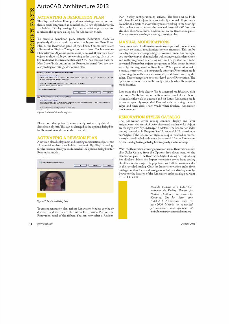
8122019 augi world 2013 10
httpslidepdfcomreaderfullaugi-world-2013-10 1452wwwaugicom October 20
PRO
DUCT
FOCUSAutoCAD Architecture 2013
ACTIVATING A DEMOLITION PLANTe display of a demolition plan shows existing construction andthose objects categorized as demolished All new objects howeverare hidden Display settings for the demolition plan type arelocated in the options dialog box for Renovation Mode
o create a demolition plan activate Renovation Mode as
previously discussed and then select the button for DemolitionPlan on the Renovation panel of the ribbon You can now selecta Renovation Display Configuration to activate Te box next toHide All New Objects is automatically checked If you want Newobjects to show while you are working in the drawing click in thebox to deselect the item and then click OK You can also click theNew ShowHide button on the Renovation panel You are nowready to begin creating a demolition plan
Please note that yellow is automatically assigned by default todemolition objects Tis can be changed in the options dialog boxfor Renovation mode under the Layer tab
ACTIVATING A REVISION PLANA revision plan displays new and existing construction objects butall demolition objects are hidden automatically Display settingsfor the revision plan type are located in the options dialog box forRenovation mode
o create a renovation plan activate Renovation Mode as previouslydiscussed and then select the button for Revision Plan on theRenovation panel of the ribbon You can now select a Revision
Plan Display configuration to activate Te box next to HiAll Demolished Objects is automatically checked If you waDemolition objects to show while you are working in the drawinclick the box next to deselect the item and then click OK You caalso click the Demo ShowHide button on the Renovation panYou are now ready to begin creating a revision plan
MANUAL MODIFICATIONSSometimes walls of different renovation categories do not intersecorrectly so manual modifications become necessary Tis can bdone by temporarily suspending Renovation mode For exampyou may have a plan that includes walls categorized as demolitioand walls categorized as existing with wall edges that need to corrected Remember objects categorized as New do not interawith objects categorized as Demolition When you need to maka manual correction you temporarily interrupt Renovation moby freezing the walls you want to modify and then correcting thedges Tese changes are not considered part of Renovation Toption to freeze or thaw walls is only available when Renovatiomode is active
Letrsquos make this a little clearer o do a manual modification clicthe Freeze Walls button on the Renovation panel of the ribboNext select the walls in question and hit Enter Renovation mois now temporarily suspended Proceed with correcting the wedges and then click Taw Walls when finished Renovatiomode resumes
RENOVATION STYLES CATALOGTe Renovation styles catalog contains display and layassignment styles AutoCAD Architecture-based styles for objecare managed with Style Manager By default the Renovation styl
catalog is installed in ProgramDataAutodeskACA ltversiongtenuStyles If the Renovation styles catalog is renamed or movethe styles are disabled and cannot be accessed Use the RenovatiStyles Catalog Settings dialog box to specify a valid catalog
With the Renovation drawing open in an active Renovation modclick Styles Catalog from the Options drop-down menu on tRenovation panel Te Renovation Styles Catalog Settings dialbox displays Select the Import renovation styles from catalcheckbox for drawings to be populated with all Renovation stylin the specified catalog Clear the Import renovation styles frocatalog checkbox for new drawings to include standard styles onlBrowse to the location of the Renovation styles catalog you wa
to use Click OK
Melinda Heavrin is a CAD Co-ordinator amp Facility Planner forNorton Healthcare in LouisvilleKentucky She has been usingAutoCAD Architecture since re-lease 2000 Melinda can be reached
for comments and questions atmelindaheavrinnortonhealthcareorg
Figure 6 Demolition dialog box
Figure 7 Revision dialog box
8122019 augi world 2013 10
httpslidepdfcomreaderfullaugi-world-2013-10 1552October 2013 wwwaugiworldcom
Inventor 2014by Mark Flayler
F
ree Autodesk Inventorreg apps You meanlike a Bloominrsquo Onion at Outback Countme in Wait you mean Inventor apps asin applications that change how Inventor
works for me and makes me more productive OkayIrsquom still in but I also still want some fried food
In this article we will take a look at severalof the free apps available in the AutodeskInventor Exchange store for trial purchase andSubscription customer benefits
DESIGN CHECKERTe first one we will take a look at is the DesignChecker that was previously called Validus and
sold through DMSI Autodesk purchased thissoftware in a manner similar to its purchaseof the iLogic code from Logimetrix a coupleyears ago Luckily I was a user back before thisacquisition so I know the tool pretty well Tefact that the software went from costing around$3000 to being a free tool delivered exclusivelyto Subscription customers is a really nice benefitfor having an Autodesk subscription right now
Te Inventor Design Checker is a productivitysolution that gives the designer insight into the
adherence of company or customer standards for
the product being designed Live Checking gives instant feedbackto the user and ensures a high level of quality for the entiredesign process
Users can use pre-defined checks or define custom checks withiLogic scripts to perform design checking Executing the on-
10 AppExchange
Reviews
Figure 1
8122019 augi world 2013 10
httpslidepdfcomreaderfullaugi-world-2013-10 1652wwwaugicom October 20
Inventor 2014
PRO
DUCT
FOCUS
demand checking updates the design checker results and enablingthe live-checking allows users to get the real-time feedback fromthe design checker during design process Te Design CheckerResults ree Browser allows users to interactively edit the objectswith failed checks and a Design Checker Results Report shows allthe passed and failed check results and allows users to export thereport to Excel Word or pdf or print the report
Now what I really enjoy about this tool is the iProperty checks andsome of the modeling checks Te machining checks I could livewithout mostly due to the fact that most companies try not to hireusers who make such drastic mistakes in machining operationsMy favorite thus far is the unconstrained sketches check thatvalidates my design before adding it to Vault I have also usedthis as a measuring stick before hiring new engineers or bringingvendor Inventor models into my design
AUTODESK REMOTETis next app allows some really nice RDP usefor Autodesk Inventor Autodesk Remote is astandalone application for Microsoft Window7 and 8 and is compatible with all Autodeskproducts It lets you drive Autodesk softwareinstalled on your primary computer from aremote computer or iPad for fast access to nativedesign data over standard networks o use itsimply install Autodesk Remote on the PC you
want to share Install it again on the machine youwant to connect from and start your connectionNote Autodesk Remote currently works only inNorth America
Autodesk Remote also has a companion applicationfor the iPad that allows you to access your hostPC from an iPad Te iPad app is optimized forAutodesk Inventor so you can work from anywhereimproving collaboration and increasing flexibilityDownlaod the iPad app from the Apple Store
Te controls in the iPad app are pretty easy to understand bthat doesnrsquot make a high-end CAD product made for the Pinstantly translatable to a touch interface You can see wheinterface elements of Inventor have started to lean more towarthis inevitable progression though
From my usage of the iPad app on my iPad 3 I found the usagelittle sluggish and gesturing a bit picky I found the use the ES
Figure 2
Figure 3
Figure 4
Figure 5
8122019 augi world 2013 10
httpslidepdfcomreaderfullaugi-world-2013-10 1752October 2013 wwwaugiworldcom
Inventor 2014
key a mandatory function as I often initiated one navigation tooland found myself trying to start something else before finishing thetool I was in In the end I see some fantastic usage on the horizonfor this app but right now it is pretty gimmicky for my taste I dopicture myself at some point on my front porch with my tabletinstead of my computer I would look cooler to the neighborhoodkids too
Be aware you will probably have to troubleshoot the setup of thisapp a bit I had to lock and unlock my computer and restart theapp several times before I got it just right
FEATURE RECOGNITIONTe Feature Recognition application converts neutral 3D CAD
models such as SEP SA or IGES solids into full-featuredAutodesk Inventor models Feature mapping could be executedautomatically or interactively as needed to maintain design intentCurrently there is one Automatic Feature Recognition commandand eight feature recognition commands you can use
Automatic Feature Recognition attempts to recognize specificfeature types and populate the browser tree with the recognizedfeatures A dialog box displays the feature types you can recognizein the Features section with the defaults checked You can selectfeatures you want to recognize and deselect features you do notwant to recognize
When you import a file it will offer to start feature recognition Ifyou decide to do it later you will have to find your Base1 solid inyour tree and right click on it to start it again
Tis tool has been around for a long time previously only on
Autodesk Labs Personally I donrsquot like it mainly because I have toconstrain and dimension the sketches when they get recognized bythe tool If your goal is to bring in a solid and then do some minormodifications to it then you are better off using the Edit Solidtools also shown in the image above If you want Work Plane toolsalso remember to turn off the Import into Repair Environment aswell before opening the file
If you really had to go the distance and recognize features it isactually a lot quicker and generally creates a more intelligentmodeling history if you just redo it yourself in Inventor Terecognition tools only lend themselves to simple parts inmost cases
Figure 6
Figure 7
Figure 8
Figure 9
8122019 augi world 2013 10
httpslidepdfcomreaderfullaugi-world-2013-10 1852wwwaugicom October 20
Inventor 2014
PRO
DUCT
FOCUS
WORK FEATURE VISIBILITYTis product allows Inventor users to manage all work featurevisibility in a fast and easy way keeping full awareness of the involvedentities Tis app consists of six buttons on part environment andanother six on assembly environment Inside of part environmenta user can choose to enable or disable the visibility property ofplanes axes or points Inside of assembly environment a user can
also choose on which components to enable or disable the visibilityproperty of planes axes or points
I had a little trouble with this app in the assembly environmentbut that was due to some bad installation files Tis is one appreally worth the $099 How often have you been in an assemblyand not wanted to go back to the part files to turn on and offwork features I recommend ungrouping them so you access bothcommands faster
SHEET METAL FLAT EXPORTTere seems to be a plethora of these apps on the Exchange witheach of them varying in price and options In general the ideabehind these apps is to help automate the process of getting a DXF
to a machine that reads them for manufacturing in a more efficientmanner Tese programs will scan an assembly file and find thesheet metal files on which to perform their routines
Te different variations of this program range from free trialsupwards of $100 for the paid apps I started with one that gave me
a ldquoliterdquo version that would do 20 sheet metal files and I liked it much I started using the full version
FEATURE MIGRATORTe Feature Migrator tool allows Inventor users to more eascreate part features from assembly features User can migraassembly features either by selecting them in the Feature Migratbrowser or by right-clicking on one or several of them and theusing the ldquoSend to Partsrdquo commands Features can also be directmigrated from the regular Inventor model browser using thcontext menu item added by the add-in
Once the operation of migrating features is completed the FeatuMigrator displays a dialog that provides information about thresults Tis first dialog is a ldquohigh-levelrdquo report of the migrationprovides the opportunity for the user to select the action to takfor all the assembly features migrated Suppress if SucceedeSuppress always Delete if Succeeded Delete always or Nothingalso for the part features that havenrsquot been migrated correctSuppress Delete or Nothing Features created by the add-in cbe in an invalid state in the parts for a number of reasons
Te user can also see when a feature is out of date from thassembly and perform updates from the part side
Figure 10
Figure 11
Figure 12
8122019 augi world 2013 10
httpslidepdfcomreaderfullaugi-world-2013-10 1952
8122019 augi world 2013 10
httpslidepdfcomreaderfullaugi-world-2013-10 2052wwwaugicom October 20
Inventor 2014
PRO
DUCT
FOCUS
TIME STAMPime Stamp is an Autodesk Inventor add-in that provides bull A low-cost simple-to-use tool that adds plot time information
to your printsbull A plot stamp that does not dirty the Inventor drawing
documentbull
A simple dockable user interface that keeps out of the way
Te ime Stamp editor lets you size position and orient thestamp relative to the adjacent sheet edges You can include datetime and current user information in the stamp Te time stamponly appears on the plot it does not alter the Inventor drawing
What I really like about this app even though it costs $500 perlicense is that you can find the price yourself and buy it It doeseverything it says it does and it provides an easy-to-use interfacewith an icon that changes based on whether the tool is on or offIf you want even more control over your plot stamping there is amore professional version offered by this company on their websitefor about $4000 a license which will allow more reporting fieldsand more control on the look and location of the stamp
SIMPLE SHEET SETTINGSSimple Sheet Settings combines the existing sheet settings withsome new tools such as changing the title block and also the abilityto make changes to all sheets in a document at once
Instead of first deleting the existing title block from a sheetexpanding the title block folder and inserting the desired titleblock then opening another window to change the sheet size andorientation just click the ldquoSettingsrdquo button located on the Sheetspanel in the Placed Views tab (right next to ldquoNew Sheetrdquo) andhave access to all those options in one location
When the Simple Sheet Settings window is loaded it gathers all the existing title block names and puts them into one drop-dowmenu o change the title block on the current sheet simply selethe desired title block from the drop-down menu and click OKTere is also the ability to change the title block sheet size ansheet orientation to all sheets at one time
Tis is a great little app that saves clicks and only costs a dollaQuite useful and no real setup involved
INTERACTIVE TUTORIALTe Create an Interactive utorial app provides instructions fcreating your own interactive Inventor tutorial Te Guide alincludes how to customize the Welcome Screen to display yointeractive tutorial and add to the ribbon
Tis one definitely falls under the ldquotoo much time on your handuser or CAD admin After reading through the guide on how create the interactive tutorials you find yourself asking the questioldquoWhy donrsquot I just save videos of the process we use in a companserver locationrdquo And that is when you uninstall this app as yohave realized that while it sounded good to you at first there abetter ways to accomplish the goal of company-specific tutoria
and process documentation
Figure 16
Figure 17
8122019 augi world 2013 10
httpslidepdfcomreaderfullaugi-world-2013-10 2152October 2013 wwwaugiworldcom
Inventor 2014
Te tools actually rely on too much externally controlled softwaresuch as Camtasia and other plug-ins and third-party apps to makeit work correctly Save your time and just use Camtasia from
echsmith to do your bidding
KEEPING UP TO DATEWith all these apps it is easy to understand how a user could getbehind on the updates to so many tools With that in mind theExchange Manager found on the ools tab in Inventor will keeptrack of that for you and offer assistance not only in updating butalso uninstalling and specialized help for each app
As a reminder with regard to third-party apps if you startexperiencing undesired effects in Inventor start turning add-ins
off one by one until you isolate which one is giving you fits Properreporting back on the app to the developers makes everyonehappier when the issue gets resolved Tus far I havenrsquot had nearas many issues as I thought I would have
ANY MANY MOREWith 80+ apps currently in the store and about 60 of them ready
for 2014 at the time of this article you should take some time andlook through what is available Tere are apps which are very nicheto the user base as well as those that have you scratching your headover why they are not already part of the core software Below aresome I would write about if I had more room in the article andora fatter PayPal walletbull BOM oolsbull EDM Expressbull Sketch Symbol Librarybull SolidWorks iProperty Importbull Quick Viewsbull 3D Pipebull Point Linkerbull Kwikools
Mark Flayler is an application engi-neer with IMAGINi echnologiesspecializing in manufacturing environ-ments He has implemented Autodeskmanufacturing products within severalindustries including the blowinjectionmolding automotive and custom ma-chinery markets When not providingtraining support and implementationhe writes the IMAGINi Manufac-turing Blog and takes an active role inthe manufacturing community Markis an AC certified instructor and isPSE and AC certified in AutoCADAutoCAD Mechanical AutoCADElectrical Autodesk Data Manage-ment and Autodesk Inventor
Figure 18
Figure 19
8122019 augi world 2013 10
httpslidepdfcomreaderfullaugi-world-2013-10 2252wwwaugicom October 20
SPECIALFEATUREAUGI Forums by Melanie Perr
The AUGI Forums are as always a busyplace Ask a question and you mightsee half a dozen varied methods andworkarounds posted in a single thread If
you have not had any questions yourself I would stilllike to encourage you to pop into the Forums and see
if there are any problems you could solve especially if you use one
of the less adopted products Tere will always be many helpinghands in the AutoCAD and Revit Forums but what about themechanical products or design visualization or structural detailingForums Peek in and see if you can share your experiences andwisdom with the community
I confess that I only scoured the English-speaking Forums forcontent for this article but please keep in mind that there areAUGI Forums available in 12 other languages so users have theoption of asking for support in their native tongue
AUTOCAD ndash SYSTEM VARIABLE
DISCUSSIONhttpbitly15M1hB9
Tis topic started out when a user couldnrsquot delete Te solution wasultimately the PICKFIRS variable but the discussion evolved tosafeguarding other variables automatically just to protect against aloss of settings in the event of a crash User Coloradomrg offeredthe safeguard shown in figure 1
Norton_cad also suggestsDIMLFAC EXPER andBLIPMODE be addedto the list
REVIT ndash
UNDERLAY
BEHAVIOR
EXPLAINEDhttpbitly15M1iFd
Mschroeder opened thediscussion with If you haveever wondered why some wallsdonrsquot show up in underlays or
show up inconsistently from floor to floor or why roofs and vieranges affect their behavior then read on
First rule of underlays Underlay view extent properties (cut rangdepth) are not user modifiable and not coupled to any othviewrsquos properties
Itrsquos also been mentioned ldquoIf objects are visible in the view ranof your current view AND in the view range of your Underlathey are automatically hidden in your underlay so there isnrsquotdouble instancerdquo
Users twiceroadsfool and dbaldacchino helped clarify the effecby posting sample models and pertinent data from the AutodeKnowledgebase and Autodesk Support Visibility View RangDetail Level and Cut Planes are all touched on in this discussioNeed clarity on how to make the most of Underlays Check inthis thread on the Forums
LISP ndash MAKING A DIALOG BOX RETAIN
ITS SELECTIONShttpbitly15JzMCc
Te LISP Forum always has such fascinating topics it is hato decide which to highlight From locking OSNAP options setting Explode options along with troubleshooting of existincode But the discussion surrounding the tutorials and metho
to retain selectioin a dialog box wvaried and lively so had to check it ou r e a v e s 0 4 4 1 3 2 1
even posted a sampdcl file when he wfinished
String Theory
8122019 augi world 2013 10
httpslidepdfcomreaderfullaugi-world-2013-10 2352October 2013 wwwaugiworldcom
AUGI Forums
AUTOCAD ELECTRICAL ndash LINES BEING
LABELED AS WIREShttpbitly1ew9p9D
Dinochrome says that one of his coworkers has reported aproblem with regular AutoCAD lines being labeled as wires
Crosswire35 advises ry checking your wire type edit dialogbox and make sure the ldquomake all lines valid wiresrdquo checkbox is unchecked
And IMCO goes on to say Using the vanilla line command inACADE will still place that line on a wire layer Change your linesto layer 0 and ACADE will not give them a wire number
AUTOCAD STRUCTURAL DETAILING ndash
TUTORIALShttpbitly17kW7cc
Te consensus is that this product is a little confusing to figure outand that most of the tutorials out there are older Most productshave a few videos floating around on Youube but this one doesnot seem to have too many yet
Jpo82 chimes in with I guess only tutorials forthis software are those found at Autodesk websiteTey are for versions 2010 and 2011 but still validhttpusaautodeskcomadskservlet12ampid=13111928 Irsquom not sure but sometimes I feel that the only new feature inASD 2013 is that itrsquos more stable than previous releases
Lucis29 goes on to say Also you might check some movieshttpwwwrobotofficecomasd but they are very old
Spenner then linked to his reporting of the Service Pack andissues it addressed hoping that it addressed some of the issuesthat came up in this discussion
NAVISWORKS ndash IMPROVE ANIMATION
EXPORT QUALITYhttpbitly1fQLoIv
Different methods are discussed from exporting individual imageframes to exporting a video (and how long) but I will leave youwith the following list from Revit For Breakfast
Here are the secrets to movies in Navisworks1 Donrsquot use materials ndash you make your render time much longer2 Use the PNG export option 15fps3 Make your video export twice as long as you need Ten speed it
up for a faux 30fps Tis is faster4 Look up the Navisworks blog by Lee Mullin and Paul Walker
about gooch and phong Tere is your faux render setting5 If you have NW 2012 you wonrsquot have gooch or phong but you
will have better export options 2013 has gooch and Phong butfewer export options
6 Te flickering occurs when multiple shapes overlap If you care
delete them in your export model Sometimes flickering occurs
in the generation of your frames on the PNG export You mayhave a frame that is ldquooffrdquo
7 Set your anti-aliasing to 4x or better on the png export8 Check out my old post httpforumsaugicomshowthread
php132209-Animation-Resolutionampp=1138298ampviewfull=1post1138298
CAD MANAGEMENT ndash NETWORK DRIVE
CHANGED BY IT WITHOUT WARNINGhttpbitly18J4k9c
Blackbox advises edinsmore595165 straight off to utilize theReference Manager program that comes with AutoCAD inorder to reconnect all of the external reference paths that werebroken when the I department upgraded their archaic serversHe further points out that moving from hard pathing to relativepathing would make things easier in the future
Feargt offers another twist Another option which would workon a need only basis when you open the specific drawing Change
XREF and Image paths in drawing to Network path throughscript on a need only basis Basically this will only change pathsPlace this line in a acaddoclsp file(command ldquoscriptrdquo ldquoyourserver and pathXREFREDIRECscrrdquo)and the following in a script fileREDIRB enter name of path to be replacedP enter new path
Tere was also a debate in this thread about obstacles and benefitsof user-managed and I-managed drive mapping
Melanie Perry is a Facilites-Manage-ment Coordinator and echnical Edi-tor in St Louis MO She is the AUGISalary Survey Manager and is curring-ly serving as an Officer on the Board ofDirectors Melanie can be reached atmistressofthedorknessgmailcomor found on witter asMistresDorkness
OTHER HOT TOPICSHave you found a Forum solution so mind-bogglinglyuseful that you leapt out of your chair with a whoopingcheer (or were at least tempted to) Please let me know Asingle person cannot read every post in our bustling AUGIForums so if you would like to see a thread highlighted ina future edition of String Teory feel free to let me knowSend me Wanderer a PM in the Forums or send an emailto MelaniePerryaugicom
See you on the Forums
8122019 augi world 2013 10
httpslidepdfcomreaderfullaugi-world-2013-10 2452wwwaugicom October 20
Revit Architecture 2014
PRO
DUCT
FOCUS
by Martijn de Rie
Myth Buster
Revit amp IFCPart 3
Irsquove given a lot of thought as to how this trilogyof articles should end At first I thought Irsquoduse the Coordination View 20 EXPRESS-GWallPaper for IFC2x3 (httpwwwmdr-
adviesnlwp-contentuploadsCoordinationView_V2-0_WallPaper_IFC2X3_Version-1pdf ) as a stepping stoneto give an ldquoIFC for Dummiesrdquo type of solution But that turnedout to be quite lengthy and rather boring But the link is includedabove for obvious reasonsmdashitrsquos useful
So I went back a little and asked myself ldquoWhy IFCrdquo And with thatquestion the inevitable follow-up immediately appeared ldquoWhynot IFCrdquo I realized that in the previous articles I failed to explainwhy in my humble opinion we should care about this somewhatcrooked badly implemented severe headache-inducing formatTerefore instead of explaining the fundamental technicalities ofIFC that can be explored in other places this final installment willexplore the Why versus Why Not IFC discussion and begin withthe latter
WHY NOT IFCWhen everybody uses Autodeskreg RevitregWell in this case itrsquos a no-brainer Share your Revit files Period
Loss of dataTis is an easier way to share data instead of hacking your wthrough IFC and praying your stuff doesnrsquot get lost in the proce
Even when you manage to export your geometry through IFtherersquos always loss of data
Loss of intelligence during importEven if you only need to send over geometry not data importithat into Revit makes it utterly useless All constraints are locomponent parametrics are gone and so on
Availability of bidirectional linksWhen not everyone uses Revit on a given project (which is quoften when yoursquore not located in the US) why not simply ua bidirectional linking between proprietary software standardTis can be easier and better to control
8122019 augi world 2013 10
httpslidepdfcomreaderfullaugi-world-2013-10 2552October 2013 wwwaugiworldcom
Revit Architecture 2014
WHY IFCWhich may be asked as why would you want to use IFC Or moreaccurately why would you want that option available
Consider what Sir Arthur Conan Doyle wrote ldquoOnce you eliminatethe impossible whatever remains no matter how improbablemust be the truthrdquo
Letrsquos put that to the test shall we
When everybody uses RevitOkay simple math Autodesk has around 7000 employees Teworld has about 72 billion people What are the chances someonenot working for Autodesk has a brilliant idea and creates thesoftware you need tomorrow Tere will always be better solutionsTey might not be viable for you overall but therersquos no reason toshut down access to them Revit is a wonderful generic tool forwhich I see a brilliant future with all kinds of additions for specificniche-markets like AutoCAD has
What about today DDS is MEP-engineering software that cando energy calculations (not simulations) inside your modelRhino lets you model things on the fly that could (arguably)take ages in Revitmdashif you ever get them done ekla lays wasteto the Revit structural rebar functionality any day of the weekwithout breaking a sweat Solibri is a wonderful solution for clashdetection and most importantly rule-based model checking andreportingmdashsomething Revit (or Navisworks) doesnrsquot do
Should I go on
Only problem for all this magnificent software Itrsquos either based onthe IFC format or requires model exchange through IFC
Te fact of the matter is there will always be better softwareAny one may be the software for you but that doesnrsquot mean yourpartners associates etc need to have the choice to use it forcedupon them
Loss of dataOn July 1 2013 there was an extra release for Autodesk softwareTe Sourceforge Open Source IFC Exporter released a new versionthat incorporated the option to map custom Revit parameters(shared or non-shared family or project even calculated values) totheir IFC counterparts
On September 28 2013 I had the honor of showing the secondstep in a complete and controllable data export from Revit
During my RC Europe class I showed the new option to create acustom IFC Property Set and map any given Revit parameter intoIFC fully customizable
IFC does not automatically lead to loss of data Tat idea is simplynot true Incomplete implementation in Revit does lead to loss ofdata As of now you are able to put any piece of data into an IFCeven calculated values And we didnrsquot change the IFC format We
just improved implementation in Revit
Loss of intelligence during importldquoJust because something hasnrsquot happened yet doesnrsquot meanitrsquos impossiblerdquo
I donrsquot know who originally had this insight and I doubt it to bethe movie line I remember but it is true
In the same RC Europe class I showed a native Revit familybeing exported to IFC altered and re-importedmdashwhile keepingall parametric constraints and even adjusting to the alterationsmade directly in the IFC file It is possible but not with thecurrent importer
Availability of bidirectional linksIrsquove been using Revit for almost 10 years now For 4-5 years I didnrsquotknow about IFC at all Before a year ago this was my strongestargument against IFC Why would you need a generic ldquolanguagerdquowith all its limitations (of which there are) weaker implementationand use of parametric capabilities (because it has) and lag-times indevelopment (by nature)
IFC will never be able to do what native software does simplybecause itrsquos responsive in nature Development budgets are afraction of what Autodesk rimble or Nemetschek get to spendon their software
So why not keep it simple and use a bidirectional link Revit has itwith a lot of other Autodesk software and third-party applications
But how long have we waited for them And are they even trulybidirectional Do they exactly do what you want them to do In myhumble opinion the answer to these questions is not very inspiringEven bidirectional links tend to have major limitations and severe
constraints in flexibility And most important Te link itself isalso propriety software No way of adjusting it to your needs
WHAT IF MORE PEOPLE STOPPED
TALKING ABOUT IT AND JUST GOT
INVOLVEDTe improbableFirst off itrsquos a matter of simple logic As Sir Arthur suggested ifwe can successfully check off all likely options to NO want touse IFC doesnrsquot that mean the improbable is true Tat IFC is infact a valuable tool in our toolkit and we should be able to use it
when necessary
Mind you Irsquom not saying you should use IFC If yoursquore on a Revit-only project it would be insane Just send and receive RVs Tefact is this will only be viable for limited parts of the buildinglifecycle If yoursquore lucky the entire design team is on Revit Butmanufacturers have other software facility managers too
As for the design team what if the best structural engineer is not[on Revit] or the MEP guy that has loads of experience in similarprojects Would you settle for second-best just because someoneuses the same brand of tools you do I wouldnrsquot
8122019 augi world 2013 10
httpslidepdfcomreaderfullaugi-world-2013-10 2652wwwaugicom October 20
PRO
DUCT
FOCUS
Revit Architecture 2013
Open AccessWhich brings us to the biggest advantage of IFC (or any open
format) itrsquos open Which means itrsquos adjustable to your needs Nowdonrsquot go ldquothatrsquos too difficult expensiverdquo Tatrsquos bullocks
Te first external enhancement to the Open Source Exporter wascreated by om Pesman a self-employed API specialist
Parametric IFCImplemented by Jon Mirtschin also self-employed IFCparametrics is available Agreed Jon is a well-known IFC guru butstill the point holds
Custom property sets and parametersWim as owner of a small MEP engineering firm hasadded functionalities toward this end and hersquos not even a trueAPI specialist
All these developments were done for free by altruistic volunteerefforts as part of the creation of the Dutch Revit Standards Andof course with the invaluable help of the Autodesk Open SourceIFC Exporter team Angel Velez in particular
But what if these guys actually got paid What if this projectwasnrsquot a Saturday night side-job What if more people stoppedtalking about it and just got involvedmdasheither by themselves or byleveraging experts to get what is needed Te entire IFC format is
Open Source the source code is out there which basically meansyou can do whatever you want and create whatever you needmdasheven on a project-by-project basis
BIM ITrsquoS THE ldquoIrdquo THAT MATTERSIn my humble opinion the entire debate on BIM is focusing on thewrong part of the acronym I donrsquot care if ldquoBuildingrdquo is a noun ora verb Nor do I care whether itrsquos ldquoModelrdquo or ldquoModelingrdquo nor am Icommenting on whether one should say ldquoBIM Modelrdquo
Itrsquos the ldquoIrdquo that matters If wersquore collaborating the Informationis most all I care about I just want your datamdashin the leanest
smartest and most effective way possible
A Revit model will do conversely a lot of times A Revit model w
give me heaps of data I donrsquot want geometry I donrsquot care about ana file format I canrsquot use Now we can all keep on being really anabout it or we can simply use the tools available to us one of thebeing IFC
A FINAL NOTEAs stated at the beginning of the article I really enjoyed writinthis series and for now this is the last of the series But if yoursquointerested in more tips and tricks on IFC let me know I might able to persuade the guys at AUGI to let me write about it againLord knows there is still a lot to talk about regarding IFC
Martijn de Riet is a self-employedBIM Consultant from the Nether-lands working with Revit since version51 Martijn has a bachelor degree inBuilding Science After his studieshe started his own engineering firmworking for contractors architects and
private clients Starting in 2007 hiscompany transformed into a full-timeBIM consultancy service At the mo-ment Martijnrsquos clients vary from mid-sized architectural firms to the largest
dutch General Contracter and MEPEngineering firms with a focus onspecific corporate solutions design andimplementations of Revit and BIMworkflows Martijn is a member ofthe Dutch Revit User Group and cur-rently working on creating a Masteremplate and Component LibraryHe provides lectures for companiestechnical universities seminars etc ona regular basis
Itrsquos the ldquoIrdquo that matters If wersquore collaborating the Information is most all I care about I justwant your datamdashin the leanest smartest and
most effective way possible
8122019 augi world 2013 10
httpslidepdfcomreaderfullaugi-world-2013-10 2752
wwwxicomputercom
8122019 augi world 2013 10
httpslidepdfcomreaderfullaugi-world-2013-10 2852wwwaugicom October 20
3ds Max 2014
PRO
DUCT
FOCUS
by Chris Murra
SUMMARY WHATrsquoS
CUSTOMIZABLE IN MAX
(HIGH LEVEL)When it comes to the customizability of Autodesk 3ds Maxregitrsquos no secret that it can morph itself into whatever you want theprogram to become
Whether yoursquore a modeler animator lighter rigger generalist ortechnical artist 3ds Max can become your own personalized toolbox that is an extension of your own hand in your daily workYou can now combine different command types (such as creatingobjects and object modifiers) into a single menu reducing themouse travel and improving efficiency
In this article wersquore going to take a closer look at one specificaspect of customization with 3ds Max the new enhanced UI Aspart of this article besides taking a deep dive into the operationof this feature I will also be showing how I created the ldquoMographrdquo
tools UI that includes custom buttons and icons At the end this article I will also provide a link to this UI so you can use customize it yourself or share it with others
ENHANCED UI SUMMARYWhat is the Enhanced UI
Te Enhanced UI is a new graphical user interface system thdoes two main things
1) It provides a refreshed 3ds Max user interface with updattool categories and new clusters of pre-existing tools in groupinthat are more akin to their intended purpose as opposed to somtechnical requirement for menu placement
2) It provides a way to allow you the end user to customize thmenu system in almost any way you choose Te drop-down menare ldquotear-ablerdquo (not to be confused with ldquoterriblerdquohellip but I digresand the resulting configurations are savable either by scene or
3ds MaxEssentialsCustomizing
the UI
8122019 augi world 2013 10
httpslidepdfcomreaderfullaugi-world-2013-10 2952October 2013 wwwaugiworldcom
3ds Max 2014
a preset Tey are also distributable and deployable so they can beshared with others
Where is the Enhanced UITe Enhanced UI can be found in the upper left hand corner of themain UI at the very top of the screen Tere is a drop-down menuthat says ldquoWorkspace Defaultrdquo Tis default is the same baselineUI that ships with all 3ds Max installs (Figure 1)
Within the drop-down you can find the ldquoDefault with EnhancedMenusrdquo Tis is the alternative default menu system that youcan use on its own or use as a starting point to create your owncustomized menus
BASIC DEFAULT CUSTOMIZATIONEnhanced UI Customization BasicsNow that wersquove enabled the Enhanced UI how can we change it
SOP Before you begin mucking around with the UI Itrsquos importantto understand what I call the ldquosave-logicrdquo as it pertains to custom UIs
Te UI Save LogicIf you plan on saving this UI for future use there is a specificmethod you must follow to properly save the UI you want and notwreck the default Enhanced UI
Te Save Logic is as follows Itrsquos simple but important
Step 1 urn on Enhanced Default UI (Figure 3)
Step 2 Click ldquoSave as New Workspacerdquo FIRS At this point youwill be prompted for a new name (Figure 4)
Step 3 Edit and change the UI at will
NOE All future edits are ldquoautomatically rememberedrdquo as you go (Iintentionally did not use the word ldquosaverdquo)
Step 4 Te ldquosave as default staterdquo button is important When wehave completed the customization process we then choose thisbutton to ldquolockrdquo in the changes Tis is different than Saving a UIwith a custom name
HO IP ldquoBut this methodology seems backwardrdquo
I can see how yoursquod say that but remember that any changes you make
to any enhanced UI are automatically ldquorememberedrdquo If you create acustom UI then while working you make some temporary changeswhen doing something specific those little changes are automaticallyremembered If you want to return to the default state [of yourcustomized UI] you select ldquoReset to default staterdquo Tis does NObring back the default Max UI rather it brings back the customizedUI you created in ldquolockedrdquo in Step 4
Okay now that you have the save logic down letrsquos begin customizing
1) If you havenrsquot done so already turn on the Default Enhanced UI
2) Go to ldquoManage workspacesrdquo from the drop-down and in the
Figure 1 Workspaces are in the Workspace drop-down menu
Figure 2 Default UI (left) and the Default Enhanced UI (right)
Figure 4 Saving the New UI Workspace
Figure 3 Turning on the Enhanced Default UI
8122019 augi world 2013 10
httpslidepdfcomreaderfullaugi-world-2013-10 3052wwwaugicom October 20
3ds Max 2014
PRO
DUCT
FOCUS
Manage workspaces dialog choose ldquoSave as new Workspacerdquo Giveit a specific name
3) Begin making your desired changes
Since a custom UI is specific to any one individual letrsquos take a lookat what types of customizations can be made
Simple ChangesOne of the simplest things to do is peel off any commandgroup (see Figure 5) Just click the group title bar and drag Tecommand group becomes a floating dialog box Now just becauseyoursquove peeled it off does not mean that yoursquove removed it fromthe drop-down menu Te ldquooriginalrdquo command group remains inthe drop-down You can just close the floating dialog when yoursquoredone with it
Probably the simplest thing you can do is reorganize the menusIn each drop-down menu appears a group of commands You maynotice that some command groups are icons and some are words(Figure 6) o change the appearance of the commands there is asmall icon in the upper right corner of each group of commands(Figure 7)
Te next change is alreally simple Is tcommand group op(expanded) or clos(rolled up) Just clion the plus or minsign in the upper le
corner to set this stafor the next time yolaunch 3ds Max (Figu8) Remember thesettings are saved as yogo so whether it is opor closed is your choicbut the state the menis in when you cloMax is the one that remembered the netime Max opens
What about Saving tDefault state More othis later
Once you have floating menu yocan combine differecommand groups dragging any othcommand group to aother floating dial
that yoursquove created Tis makes for easy creation of custom dialo
based on specific tasks Figure 9 shows a command group fcharacter animationFigure 5 A floating menu that has been torn off the drop-downmenu
Figure 6 The different display states of the menus
Figure 7 Changing menu layouts
Figure 8 Rollouts
8122019 augi world 2013 10
httpslidepdfcomreaderfullaugi-world-2013-10 3152October 2013 wwwaugiworldcom
3ds Max 2014
ADVANCED CUSTOMIZATION
What about completely custom interfaces Herersquos how we do thatwith the Enhanced UI menu system
Te following is the high-level overview of the process Wersquoll thenunpack each step in more detail
If you havenrsquot read the section on Basic default customizationplease do so before continuing Before starting this phase ofcreating your new UI you should have saved your new UI stateTat process is explained in the previous section
1) Create a main drop-down menu (like ldquoMy oolsrdquo)
2) Create a tools category menu into which you will place yourtools (a submenu such as ldquoModeling oolsrdquo or ldquoAnimation oolsrdquo)Drop-downs can have more than one subcategory
3) Add commands to various submenus
4) Clean up the UI by creating custom names adding separatorsor creating custom icons
First letrsquos create a new menu for the menu bar Tis is done easilyfrom the CustomizegtCustomize [Rollout]gtCustomize UserInterface dialog box
Steps for Creating a Drop-Down Menu1) Create a New Menu and give it a name (see Figure 10)
2) Locate your new menu in the Menus window It will be listedalphabetically (Figure 11)
Figure 9 Multiple command groups in one menu
Figure 10 ndash Creating a new drop down menu
Figure 11 Location of new menu
8122019 augi world 2013 10
httpslidepdfcomreaderfullaugi-world-2013-10 3252wwwaugicom October 20
3ds Max 2014
PRO
DUCT
FOCUS
3) Drag your newly created menu category over to the column onthe right Tis will add your new drop-down menu to the interfaceimmediately and you can begin populating it with menu items (seeFigure 12)
UI DESIGN IP Te actual menu name and display name can bedifferent I used a custom menu name behind the scenes so I couldeasily differentiate my menus from the ones created by default or other
tool companies After you create a menu and add it to the right column you can right-click on it and change its display name (see Figure 13)
Next letrsquos create a command group1) Just like in Step 1 from the previous section create a new men
2) Tis time before you drag it to the right column click thplus sign next to your drop-down menu item to expand it Tedrag the new item to the right column dropping it ldquounderrdquo thmenu name
3) Drag any commands from the Commands window on the leto the submenu on the right (see Figure 15)
Herersquos an example from my Mograph ools workspace thshows how a completed menu looks once it is created (Figu16) In the following figure you see both the menu as it appeain the Customize UI dialog and the actual menu (which has bepeeled off)
Notice that some of the commands on the menu are greyed ouTatrsquos because this new menu combines both ldquoObject creatcommands and ldquoObject Modify Commandsrdquo in one menTey will remain grey until you create an object on which thwill be used
Figure 12 Adding the new menu to the UI
Figure 14 Creating a command group
Figure 15 Dragging commands onto the menu
Figure 13 Custom menu names
8122019 augi world 2013 10
httpslidepdfcomreaderfullaugi-world-2013-10 3352October 2013 wwwaugiworldcom
3ds Max 2014
Adding SeparatorsSeparating commands is easy and is recommended to help you oryour intended user make sense of the how the tools are arranged inthe menu Creating a separator is as easy as dragging one over theright column just like a menu or command
HO IP ldquoWhy do I need to create another menu Why canrsquot I addtools right to my menurdquo
Te main reason is that adding a submenu gives you the ability to tearoff the submenu If it werenrsquot in a submenu it wouldnrsquot be tear-ableSo itrsquos really a ldquobest practicesrdquo kind of thing But even if you try to notadd the submenu it will happen automatically Itrsquos important to do it
explicitly so you are aware of what submenus are in the menu and that you are the one in control of what command is going where
CUSTOM ICONSNo custom UI is complete without a custom set of iconsAdditionally not all commands in 3ds Max have their own iconyet But itrsquos important to realize that regardless of how you set up
your UI yoursquore still working within the framework of an existingapplication and there are boundaries to what you can edit andcreate Icons have specific requirements both in their creation(size) location and file name that must be adhered to in order forthem to work properly
SizeformatTe size of icon is pretty simple It must be 32x32 pixels andPNG format
LocationTe location is very specific New icons must be added to thislocation
CProgram FilesAutodesk3ds Max 2014UI_lnResourcesDarkIconsMain
Te new icons I created for the Mograph UI are shown inFigure 17)
Icon File NameIf yoursquore still with me at this point we are now getting into thenether regions of customizing a UI Tis is where things get a littletricky but itrsquos really not too bad File names are specific and aregenerated by the application (3ds Max)
So letrsquos begin First identify the command for which you want aniconmdashusually itrsquos one that doesnrsquot already have an icon But if itdoes and yoursquore changing it MAKE A BACK UP of the originalicon PNG file Tis is because as previously stated you donrsquot havecontrol over the file name Tat means if yoursquore creating your ownicon you need to overwrite the existing one and use its name foryour new icon So back up any original icons
Figure 16 The completed menu
Figure 17 ndash The created icons
8122019 augi world 2013 10
httpslidepdfcomreaderfullaugi-world-2013-10 3452wwwaugicom October 20
3ds Max 2014
PRO
DUCT
FOCUS
It really doesnrsquot matter whether you make the icon first or not ofind the name you need to use you need to navigate as follows
NOE Yoursquore about to edit the ribbon Tere is no need to save thesechanges as we are merely extracting information from it But if yoursquoredoing a lot of custom icon work you may want to save this change to theribbon so you can come back and continue your work in later sessionswithout have to recreate this every time just to get the proper file nameSaving this ribbon is not related to saving your default state of yourUI When yoursquore done creating all your UI icons you can just delete
whatever changes you make to the ribbon
1) Open the ldquoCustomize Ribbonrdquo dialog box
2) Create a new ldquotabrdquo by dragging it onto the ldquoExisting Ucolumn in the middle (see Figure 18)
3) Using the same drag method add a new ldquopanelrdquo to ttemp tab (Figure 19)
4) Now you can get the information you need Find tcommand for which you are creating an icon and dragto the panel
5) Locate the ldquoinfordquo portion of the ldquoPreview Windocolumn At the bottom of the column is the file namneeded to have the icon used properly by the applicati(Figure 20)
CONCLUSIONSo now you know how to create a custom UI scheme f3ds Max 2014 and up By using the Enhanced UI me
system itrsquos really easy to generate a multitude of workspathat allow Max to work the way you want to work
Te example used in this article was the ldquoMographrdquo UI thI created for NAB 2013 If you would like to downloand install it you can get it from my ldquoPinning the Stacblog on the Area herehttpareaautodeskcomblogschrismurray
Enjoy
Chris Murray works for Autodesk
Media amp Entertainment He istrained as an animator (3D variety)but considers himself a creative tech-nologist His daily role is a technicalldquoevangelistrdquo for Autodesk creating marketing deliverables for 3ds Max Heis the author of Mastering 3D StudioMax He has a Masters in Fine Arts(MFA) in Computer Animation fromMiami International University of Artand Design Follow him on witterchrismmurray
Figure 18 Creating a tab on the ribbon
Figure 19 Adding a panel to the tab
Figure 20 Finding the required file name
8122019 augi world 2013 10
httpslidepdfcomreaderfullaugi-world-2013-10 3552
AUGIMembersReach Higherwith ExpandedBenefitsAUGI is introducing three new Membership levelsthat will bring you more benefits than ever beforeEach level will bring you more content and expertiseto share with fellow members plus provide anexpanded more interactive website publicationaccess and much more
MEMBERMEMBER MEMBER
Basic members haveaccess tobull Forums
bullHotNews (last 12 months)
bull AUGIWorld (last 12 months)
DUES Free
Premier members haveaccess tobull Forums
bullHotNews (last 24 months)
bull AUGIWorld (last 24 months)
DUES $25
Professional members haveaccess tobull Forums
bullHotNews (full access)
bull AUGIWorld (full access and in print)
bull ADN 2013 Standard Membership Offer
DUES $100
Are you ready to upgrade yourself and your membership
Access additional benefits and upgrade at wwwaugicom
8122019 augi world 2013 10
httpslidepdfcomreaderfullaugi-world-2013-10 3652wwwaugicom October 20
AutoCAD MEP 2013
PRO
DUCT
FOCUS
by Vladimir Triantafillid
BIM IsWhatrsquos
Driving theIndustry
For the past decade many would arguethat building information modeling(BIM) has metastasized aggressivelythroughout the AEC industry but what
does BIM really mean More importantly whatdoes it do for us and for our industry Ask someone who hasbeen in this industry for more than 25 years or those nearingretirement and yoursquoll find that less than half see its value muchless care to make the effort with its implementation hesequestions mean something different for those who have beenin the industry the past 10-15 years Recent college graduates
however with their tech-savvy capacity and high expectationare eager to implement anything that resembles cutting-edgflashy technology ypical ly they are the ones most receptivenot adamant about putting their talents to use through BIM
I recently gave a BIM presentation with an emphasis on mchanical systems to the summer interns and new hires our companymdashall were non-BIM users except for onemdashbmy presentation did little justice to BIM Half of my audence had found a cure for their insomnia when they realizthis wasnrsquot the latest edition of ldquoCall of Dutyrdquo hat was n
8122019 augi world 2013 10
httpslidepdfcomreaderfullaugi-world-2013-10 3752October 2013 wwwaugiworldcom
AutoCAD MEP 2013
reflection on BIM by any measure Simply put I fell shortof connecting with a potentially captive audience eager toknow what really makes BIM intriguing or how it wouldgive them an edge in the industry I didnrsquot think to look pastpresenting the facts of its processes and benefits o simplyhave stated that proficiency in any of its many facets willpromote a lucrative career would give those still awake theimpetus to jump ship In hindsight the first step I shouldhave taken to begin this presentation was to ask what theywanted to get out of BIM
If you think itrsquos hard conveying the value and splendor ofBIM to receptive and impressionable young minds try toconvince the weathered veterans dead-set in their ldquooldtricksrdquo For every experienced veteran who has converted toBIM there are two ldquoold dogsrdquo that canrsquot shake ldquothe good olrsquodays when we used vellum and light tablesrdquo Guess whatmdashanincreasing amount of naysayers are starting to come aroundincluding those who say theyrsquove been burned by BIM in thepast hey are seeing the simple solutions BIM presents and
how these solutions translate into cost savings More andmore of those who had formerly questioned BIMrsquos utility areconvinced when installation efficiencies are not only real-ized but quantified
Another factor in the evolution of BIM is its tendency toexpand faster than the pace of its general population of us-ers hose of us proud to be catching up to what we think iscutting edge quickly realize it was just another false sense ofaccomplishment as BIMrsquos web continues to grow exponen-tially he solution is rather simple Focus on what you canhandle and always have the presence of mind and sense ofcaution to avoid being overwhelmed by the wake of BIMrsquos
progress herersquos plenty of money to be made and countlessfacets to explore as long we have the following mentality Welive in the information age and those wi lling to share knowl-edge will reap the rewards of communal synergy
On the opposite end of the spectrum you might find ourindustryrsquos opportunists In a hurried frenzy to claim theirspot in the intellectual property queue these opportunistsget carried away with pioneering what they assume is the lat-est improvements to BIM Instead of stopping to absorb anddevelop the benefits of 4D 5D 6D and so on the pioneersare spreading these ldquoDsrdquo thin with abandon further expand-
ing the gap between quality and quantity None of this i s tosay that wersquore heading in the wrong direction On the con-trary letrsquos call it more of a positive economic problemmdashthedemand for BIM expertise and development outweighs thesupply of available users
Fortunately as collegiate curricula catch on to this industrytrend the point of equilibrium will soon follow For as longas I can remember respective companiesrsquo 2D CAD depart-ments have been a significant source as the breeding groundfor potential BIM users While this route hasnrsquot changedregarding the career path of a draftsperson the source poolhas expanded to include architects engineers and construc-
tion managers just to name a few Itrsquos even hard not to noticeits stark demand when BIM and Revit courses are being in-creasingly offered at local community colleges I knew thenthat you didnrsquot necessarily need an undergraduate degreeback when I got my foot in the door of this industry hisprobably wonrsquot hold true in the coming years Still the privi-leged few who are already a part of this industry subset canrely on their experience in this fast-paced market to con-tinue to propel their careers forward ever faster All thesefew need to do is grab onto a small piece of BIMrsquos wing andhang on tight for the ride he fresh-out-of-college e ntrantsmight have a harder time grabbing onto this wing thatrsquos al-ready in motion
o those who are only vaguely famili ar with BIM it is typi-cally perceived as the equivalent of a 3D role-playing videogame In this case itrsquos not difficult to capture a ldquosnapshotrdquoimage of a 3D model shadows cast across random metal ob-
jects taking up space in an orderly fashion between ceil ingspaces and walls What is difficult is conveying the abun-dance of value behind the pretty picture to a client whorsquosonly interested in the pretty picture Who isnrsquot familiar withthe adage ldquoa picture is worth a thousand wordsrdquo Why notchange that saying to ldquoa BIM model is worth five thousandhyperlinksrdquo Now wersquore talking lifec ycles and facilities man-
More and moreof those who had
formerly questioned
BIMrsquos utilityare convinced
when installationefficiencies are notonly realized but
quantified
8122019 augi world 2013 10
httpslidepdfcomreaderfullaugi-world-2013-10 3852wwwaugicom October 20
AutoCAD MEP 2013
PRO
DUCT
FOCUS
agement his supposed video game has suddenly becomean encyclopedia of usable information But wait itrsquos not juststatic information thatrsquos stuck on a DVD on a shelf i n someownerrsquos random storage closet It has now become a livingdynamic source of real-time data Maintenance technicianswill know exactly where to go when the active 3D modelloaded on their laptop highlights a hot water pump needingservice while concurrently bringing up the cut sheets andoperation and maintenance manuals specific to that pumpor system Better still the source of information has shiftedfrom multiple stacks of large drawing sets collecting dust toseveral hundred gigabytes on a hard drive Yes Mrs Clientyour 3D BIM model will be usable for the next 20+ years
Even though you might not necessarily think about i t someof you probably realize that BIM has become the ldquomiddle-manrdquo for so many key components in the construction cyclewell beyond its intermediary role between design and con-struction phases You want to do some significant tenantimprovement in an existing building Laser-scan the exist-ing conditions hatrsquos BIM Is the general contractor rackingtheir brain trying to f igure out where to station the crane forthe project or pave the pathways for delivery trucks Nowtheyrsquore looking to BIM to answer these questions and opti-mize their decisions o take it a step further at which endof the building do we want to load thousands and thousands
of pounds of sheet metal and pipe And then which tradesshould be installing their systems first in any given area ofthe building hatrsquos right wersquore deriving sequencing andtimelines from the BIM model to e stablish the best routes totake while addressing any constructability issues BIM hasbecome the consultant that wears most of the hats Itrsquos ourone-stop shop
I know that Irsquove personified BIM as if itrsquos the brains behindall of its success Letrsquos take a moment to focus instead on itscollaborators or the sum of its integral parts to show thatin reality we are Dr Frankenstein and BIM is our monster
Except in our ca se wersquore beginning to ta me our monster anthose who were previously frightened by it are starting to sthat it indeed is no monster In fact while evolving to domdashand becomemdashgreater things BIM is transforming into aindustry hero he point of convergence is approaching bcause wersquore saving money time and even trees Soon enougBIM will be the industry standard even on the smaller proects Letrsquos keep the pedal to the meta l
You want to know the best news Most of us havenrsquot evebegun to scratch the surface of BIM but wersquore in strategpositions to reap the rewards aking the possibility of ivast potential into account isnrsquot it reassuring knowing th
in these tough economic times wersquore engaged in an industthat has a shortage of well-qualified BIM experts Our eposure alone sets us up for success Now ask yourselves thquestion Is BIM driving our industry or is it the BIM use
Vladimir riantafillidis works for aleading mechanical contractor in theSan Francisco Bay Area with morethan 10 years of experience in the in-dustry Although he has a bachelorrsquosdegree in biology his unique careerchoices have firmly rooted him in a
substantial BIM role awarding himthe opportunity of progressing along-side the relentless evolution of BIMOutside of his career hersquos always opento new adventures whether trying anew cuisine exotic travels or extremesports Te latter adventures have re-cently subsided as the balance of lifehas shifted his focus on spending timewith his growing family
You want to know the best news Most of us havenrsquot
even begun to scratch the surface of BIM but wersquore
in strategic positions to reap the rewards
8122019 augi world 2013 10
httpslidepdfcomreaderfullaugi-world-2013-10 3952
8122019 augi world 2013 10
httpslidepdfcomreaderfullaugi-world-2013-10 4052wwwaugicom October 20
Revit Structure 2014
PRO
DUCT
FOCUS
Streamlining
Sheet Listswith a Custom
Application
In this article we take a brief look a simpleadd-in for Autodeskreg Revitreg named X-Sheetswhich provides tools for incorporating sheetsfrom an AutoCADreg sheet set in a Revit sheet
list ypically this is handled by manually addingplaceholder sheets to the Revit sheet list Tis can be problematicbecause the sheet list becomes disconnected from the sourceand must be updated manually With X-Sheets sheet set datais exported directly from AutoCAD linked to a Revit project
and included in the sheet list by automatically addingupdatinplaceholder sheets For this example all structural scheduleplans elevations and section sheets are in Revit Structure Adetail sheets will be pulled from an external AutoCAD sheet set
X-SHEETS RIBBON PANEL Te first command on our ribbon panel is Discipline Tcommand is used to establish the Revit project parameter twhich the AutoCAD sheet subsets will be mapped For th
by Jonathan Albe
Figure 1 Revit X-Sheets ribbon panel
8122019 augi world 2013 10
httpslidepdfcomreaderfullaugi-world-2013-10 4152October 2013 wwwaugiworldcom
Revit Structure 2014
example we have created a project parameter named My DisciplineParameter Each Revit Structural sheet has been assigned a valueof SRUCURALmdashthe same as the subset name for theAutoCAD detail sheets Te sheet list is grouped and sorted bythis parameter
Te next command on the ribbon panel is Links Tis command isused to establish a link between the Revit project and XML file(s)
containing sheet information exported from AutoCAD You cancreate as many links as needed and use relative paths if required
Te next two commands Sheets and Update do the work ofaddingupdating placeholder sheets to the sheet list While theSheets command allows you to select individual sheets from linksto include in the sheet list the Update command includes all sheetsfrom all links
EXPORT SHEETS FROM AUTOCADFigure 3 shows the AutoCAD X-Sheets ribbon panel and asample sheet set containing structural detail sheets Notice thedetail sheets are grouped under a subset named SRUCURALTis subset name can be exported with each sheet and mapped to
the My Discipline Parameter in Revit Figure 3 shows the ExportSheets dialog with an option to include subset information and theability to exclude individual sheets Selecting the Export buttonprompts us with a dialog to save an XML file to be linked into ourRevit project
Figure 2 Discipline command dialog
Figure 3 AutoCAD X-Sheets ribbon panel and sample sheet set
Figure 4 Export sheets dialog
Figure 5 Export complete
8122019 augi world 2013 10
httpslidepdfcomreaderfullaugi-world-2013-10 4252wwwaugicom October 20
Revit Structure 2014
PRO
DUCT
FOCUS
ESTABLISH LINK TO XML FILE IN REVIT
PROJECTFigure 6 shows the Manage Links dialog A link has been added tothe XML file we generated when exporting sheets from AutoCADNotice there is an option to make the link path relative to our
Revit Project location
IMPORT SHEETS FROM XML LINKFigure 7 shows the Revit Structure sheet list before any sheetshave been imported from AutoCAD After selecting the Sheetscommand we are prompted with a Manage Sheets dialog
For this example we have selected all sheets from the XML linto include in our sheet list After confirming the dialog neplaceholder sheets are immediately added to the sheet list angrouped according to the SubsetDiscipline mapping Te neplaceholder sheets are identified behind the scenes as being relatto the X-Sheets XML link for later updating
Figure 6 Manage Links dialog
Figure 9 Sheet list after import
Figure 7 Sheet list before import
Figure 8 Manage Sheets dialog
The X-Sheets
add-in is a great tool
for incorporating
AutoCAD sheets into
a Revit sheet list
8122019 augi world 2013 10
httpslidepdfcomreaderfullaugi-world-2013-10 4352October 2013 wwwaugiworldcom
Revit Structure 2014
UPDATE SHEETSFigure 10 shows the Export Sheets dialog in AutoCAD afterdetail sheets have been renumbered to include ldquo-Ardquo When changesare made to AutoCAD sheets the original export steps must befollowed to replace the XML file linked to our Revit project Oncethe XML has been replaced simply run the Update command inRevit to update the sheet list
SUMMARYTe X-Sheets add-in is a great tool for incorporating AutoCADsheets into a Revit sheet list Te add-in saves time by automatically
adding placeholder sheets eliminates room for error in manualtranslation and helps to keep your sheet list up to date withminimal effort
Jonathan Albert is co-founder of BIM- pulse echnologies LLC amp SeniorApplications Developer at LindemanBentzon Bojack Engineering in Cler-mont Florida He has worked morethan 15 years implementing and usingBIM echnology for some of the na-tionrsquos leading production home build-
ers Most recently he has developedBIMpulse an Options Managementand Material akeoff Add-In for Au-toCAD Architecture Revit and Au-todesk Design Review Jonathan can bereached at jonalbbecom
Figure 10 Export Sheets dialog after sheet renumber
Figure 11 Update complete
Figure 12 Sheet list after update
The X-Sheets
add-in is agreat tool for
incorporatingAutoCAD
sheets intoa Revit
sheet list
8122019 augi world 2013 10
httpslidepdfcomreaderfullaugi-world-2013-10 4452wwwaugicom October 20
AutoCAD Civil 3D 2014
PRO
DUCT
FOCUS
by Tench Tilghma
Itrsquos a fact Jack You invested money in the worldrsquosmost popular civil engineering and designsoftware You (or someone else) will have workhard to make the software run productively
and publish the engineering design or surveywork acceptably
Every AutoCADreg Civil 3Dreg user will tell you ldquoYou need a Civil3D templaterdquo
heyrsquore right sort of You need more than one he suppliedexample Autodesk template files (dwt) are just thatmdashexamplesto show you that things are possible A great many ldquothingsrdquo arepossible in Civil 3D It is data-centric model-based software Asa dedicated content developer and continuous customizer of Civil3D I hope the following perspectives and tips help shorten thecycles and reduce the pain of customizing the software
AutoCAD Civil 3D was constructed from the ground up todisconnect the survey and engineering data from how that missioncritical data is represented
WITH LIBERTY COMES RESPONSIBILITYAs far as Autodesk is concerned what you want the many Civil 3Dldquothingsrdquo to look like and how the Civil 3D data is to be annotated istotally up to you hatrsquos not really true is it Plan sets are publishedin arcane symbolic graphic languages designed to faithfully conveythe design intent to someone who must build it with a plan checkeror two (or three or four) stuck in between
As a professional I prefer to call them ldquoPlan Set Languagesrdquo hhelps focus the development to the publishing of Civil 3D datMost people throw a fuzzy word around this complex mix human perceptive agendas and call that ldquoCAD Standardsrdquo
ldquohe wonderful thing about standards is there are so many of themndash Grace Hopper et al
PICK A STANDARD AND MANAGE BY ITldquoWe already have a CAD standardrdquo his may be the first anworst Civil 3D customization mistake any skilled AutoCAD usor organization can make he odds are the CAD standards yoemployed before do not take into account the data centric anmodel-based methods that Civil 3D employs Simply put Civ3D manages how things look and behave by Style Primitive-basAutoCADreg standards may get in the way
Older ldquoCADrdquo standards by definition must be focused on CAprimitive publishing specifics layer textstyle (height) blo
CustomizeCorrectly
Figure 1 Standards documentation is required
8122019 augi world 2013 10
httpslidepdfcomreaderfullaugi-world-2013-10 4552October 2013 wwwaugiworldcom
AutoCAD Civil 3D 2014
graphics standards and so on In raw AutoCAD and AutoCAD-based drafting and design software the only way to manage all theCAD primitive stuff was to be SPECIFIC about all the details allthe time he drawing we create and check things in is the drawingwe publish
If you publish work out of quality control or design drawingsin Civil 3D this is a sign you may be missing some of its timesaving advantages
While the old CADD process works it requires a lot of man-hoursdedicated to maintaining and checking the details Clearly one ofCivil 3Drsquos critical design development goals is to rid organizationsand Civil 3D users of this expensive man-hour burden and costhe idea here is to put the man-hours into the iterative engineeringprocess instead Civil 3D Feature data and Style make this possible
Civil 3D styles and label styles do employ the AutoCAD layertextstyle block references AutoCAD customizers are used tohe software is still called ldquoAutoCADrdquo Civil 3D after all Our
AutoCAD customization skills still apply But we must applythem differently and much more systematically Herersquos whyhellip
YOU NAME ITmdashTHE MOST CRITICAL
STANDARDCivil 3D Styles and label styles employ (reference) the AutoCADldquonamedrdquo parts to ldquoexpressrdquo themselves Style tools just look for andmatch the ldquorightrdquo names Change the ldquomeaningrdquo andor definitionof the names and you can change anything
We call this fundamental property and benefit of object-orientedprogramming the Power of Names In programming speak this
concept and practical reality is called a ldquonamespacerdquo
Such a namespace in engineering speak answers the questionldquoIn this context does ldquoDIrdquo means a ldquodrop inletrdquo In a minute wersquollget to the structure of a customization ldquonamespacerdquo for Civil 3DAutoCAD references
THE POWER OF NAMESGo ahead and make a drawing from your current Civil 3D templateoss in some Civil 3D data by data reference from any projectUse the RENAME command on any of the old AutoCAD stylecollectionsmdashtry layers
Rename like crazy Your existing Civil 3D styles and label styles willhappily work exactly the same he components in the Civil3DFeature and Label Styles will go to your renamed layers Becauseyou didnrsquot change the properties of the layers either nothingchanges Itrsquos not too exciting until you think about what it means
FOLLOW A SCRIPTObviously as customizers we never want to do this sort of workmanually Computers are faster better and more exact typists thanwe are We commonly rely on AutoCAD scripts generated from
Microsoft Excel spreadsheets (See the end of the article)
here are a couple of key collections in the object model thatCivil 3D walls off from this form of potentially destructiveuser madnessmdashObject Properties in Drawing Settings and afew things like Figure Prefix Dbs values that are not ever in thedrawing per se
WHAT REALLY MATTERSAutoCAD Civil 3D style is mind-boggling abstraction Everythingis designed and built to point at references We can employ styleabstraction for our benefit
In one sense AutoCAD Civil 3D style doesnrsquot care aboutAutoCAD layer standards block libraries textstyles colorsplotstyles or really anything else AutoCAD From our perspectiveall the Civil 3D styles care about are the arbitrary and exact namesthey currently reference
he Civil 3D customizerrsquos dilemma Keep book on the exactnames here are a lot of names to keep track of You must havea plan You must have rules You must employ the same processesconsistently in the same order to get quality assured results
Figure 2 Are description keys a namespace
Figure 3 Rename the AutoCAD reference names
8122019 augi world 2013 10
httpslidepdfcomreaderfullaugi-world-2013-10 4652wwwaugicom October 20
AutoCAD Civil 3D 2014
PRO
DUCT
FOCUS
hat Current word is a wonderfully relative term forthe customizer
Build a set of styles extract them to another drawing rename andor redefine the references and quickly produce a different resulthe Current method makes it easy to propagate success andmistake It makes it repetitively tedious to make fixes
NO CAN STOPAs innovative content developers for Civil 3D we chose to employthe National CAD Standard (NCS) as our fundamental Namestandard Not because we like the NCS but because of all thehard-won experience expressed in these tested standards Inmany respects we employ the NCS UDS (Uniform DrawingStandards) etc in our Production Solution products becauseof the underlying How and Why for those standards and theirpractical published Rules
We want to build faster high-performance vehicles Why reinventthe wheel when we can improve on it
STANDARD KEYS TO NAMEShe NCS employs a hierarchical concept of Keys here areMajor Keys Minor Keys etc that have order precedence and aninterpreted meaning he NCS Layer standard employs the Key-based rules to produce defined meanings to Layers
You can in practice employ the same Layer Keys to be genericor granularly specific about where the published results go Allthe annotation can go to one layer or many different layers forexample Styles andor sets do the work
his KEY CODE structure produces a flexible and structuredldquonamespacerdquo we referred to earlier Itrsquos a namespace that both thesoftware can employ and is relatively easy for us dumb-bunnyhumans to learn to decode when we must Most of the time theusers donrsquot and shouldnrsquot care anyway
Figure 4 shows a few of the NCS ldquolikerdquo Keys we employ in ourproducts We employ them for both layer and block collectionsand even the structure of libraries hey may even be employedin Civil 3D style names when thatrsquos appropriate (See the endof the article)
he customizing key point is that the meanings of these specificKeys can be translated into any other set (or sets) of different
Keys he Key changes can be systematically applied to whatevAutoCAD reference tables and resources we require
he results of any changes will float uphill to the named Civil 3Styles we choose to employ hink of all the AutoCAD referencin a template as a Set
BEYOND AUTOCADNow wersquove looped back to Civil 3D style tools and substantivetheir names and what their parts refer to Welcome to the circuland iterative world that is customizing and employing Civil 3D
Aside from the requisite customization skills and experience build style tools our practical biggest customization issues afrankly Civil 3D human interface issues
No matter how you cut it you have a very limited amount of tespace to help users decide on the ldquorightrdquo style tool to use he teof the style toolrsquos name is all you get to deliver to the user ypicaitrsquos a pick box list
You might get lucky and have the Style Viewer but that Viewcannot represent everything a style can do
FEATURE STYLES NAMESWhat we call the ldquoFeature Stylesrdquo (the Ci3D Featurersquos graphics) require that our stynames explain in simple readable humterms what the tool does For examplesurface style like ldquoContours 1-5 Proposed
Figure 4 Some standard keys
Figure 5 The limitations of user style choice
8122019 augi world 2013 10
httpslidepdfcomreaderfullaugi-world-2013-10 4752October 2013 wwwaugiworldcom
AutoCAD Civil 3D 2014
For the common and most understood features this makes somesense ASCII order rules how named Styles organize Names mustsort that out
Complex graphic features such as Views have a lot more going onldquoMy Standard Profile Viewrdquo doesnrsquot cut it except in a publishingtemplate he style names must be more informative and specificDoes the Profile View include grid lines or not We must recognizethat the engineering data behind what we want to visualize isvariable and the user will have specific needs to get work doneWhen you check a surface you need to see the data in differentways than when the result is published
Choice of style is productive Choice is not contrary to publishingstandards unless you mix the two
LABEL STYLE NAME FACTORSWhen we open the Alignment Label Style collection andorstart to assemble Sets of Label Styles we see any hope of namesimplicity for label styles disappears in a flash
he majority of styles are annotative here are a lot of formsand specific types of them Label Style ype matters he smartcustomizer employs the Label Style Default (LSD) hierarchyexpressed in the oolspacegtgtSettings tab or ignores it and missesthe benefits
Label styles often must have a geometric framework to themItrsquos about ldquoreadabilityrdquo and meaning Whether this label goes upor down or attaches here and not there is critical to annotativeclarity he graphic structure of many data-rich label styles alsofundamentally matters to the stylersquos upgrade stability herersquos
a maintenance cost to pay if you refuse to employ consistentgeometric structures in label styles
CUSTOM USAGECan users see the right data and at the right time Will the useremploy a general alignment parcel or figure line and curve labelHow do they see the difference in a simple list It is easy to misshow ldquoon-the-flyrdquo annotative information negatively or positivelyeffects design time decision making and quality control Peoplewill make things to get the job done Do you fight it or enable ithe Simple Style Rules anyone can learn
THE CIVIL 3D NAMESPACESA Civil 3D style naming convention must be human readablecreate order in the interface and therefore include a rule-basedeasy-to-learn code system that expresses quickly the critical detailso customize we need two namespaces One for the top-end stylesand one for the back-end AutoCAD references In productionprojects we need a third namespace for how we name the featuresbut thatrsquos another story
his client and this project demand these CAD standards specificsAnother client and project demand something different Even ifyou donrsquot believe you regularly face that common problem you
still have to improve the internal production templates themselveshe method and process arenrsquot different
In our project-based production world Civil 3D users andsupervisory staff can always work with the familiar and publishwhat is demanded in a customized publishing template hetwo-pronged project template approach has the added benefit ofpotentially quantifying the costs and real return on investment forthe customization itself
CUSTOMIZE TO PUBLISH ON DEMANDIn practical terms we can change the expressed graphicsmdashthe PlanSet Language (CAD standards) with managed intern level staffEven non-CAD people can see and identify graphic differenceOnly basic AutoCAD and basic spreadsheets skills are requiredfor much of the work if you have a naming plan ldquoChange thatmanhole block to look like this manhole blockrdquo Your ldquothatrdquo mustbe specific
ldquoPublish on demandrdquo capability is a productivity and competitive
advantage but it takes repetitions to develop and practice the skillsWe must endlessly customize Civil 3Dmdashreap the benefits
CIVIL 3D NAME RESOURCEShe Standard Keys the NCS-like AutoCAD reference namespacehe Jump Standards includes the detailed and documented stylenamespace Find them at wwwcadpilotcomresourcesaspx
Excel Cell Formula Script ExampleHerersquos the pseudo code for a typical formula-based layer script thatmakes a layer table with all the details filled in from a cell It createsa series of quote wrapped strings when a column of such cells is
copied and pasted to an ASCII text file
ltLayerCommandgtampCHAR(13)amprdquoSrdquoampCHAR(13)ampltOldLayergtampCHAR(13)amprdquoRrdquoampCHAR(13)ampltNewLayergtampCHAR(13)ampltNewLayergtampCHAR(13)amprdquoCrdquoampCHAR(13)ampltColorgtampCHAR(13)ampCHAR(13)amprdquoLWrdquoampCHAR(13)ampltLineweightgtampCHAR(13)ampCHAR(13)amprdquoPSrdquoampCHAR(13)ampltPlotstylegtampCHAR(13)ampCHAR(13)amprdquoDrdquoampCHAR(13)ampltDescriptiongtampCHAR(13)ampltNewLayergtampCHAR(13)
ench ilghman is President ofMoreCompetency Inc an Autodesk
Developer Partner specializing in in-novative Civil 3D Production Solu-tion products and consulting services
for AutoCAD Civil 3D ench is aregular speaker at Autodesk Univer-sity and AEC industry events on thetopics of technology adoption innova-tion and (his personal favorite) peopleskills He posts on the Get the Jump onCivil 3D blog
8122019 augi world 2013 10
httpslidepdfcomreaderfullaugi-world-2013-10 4852wwwaugicom October 20
Revit MEP 2014
PRO
DUCT
FOCUS
by Todd Shackelfor
W
hen any new technology hits theground there are plenty of false startsand backtracking In time shortcutsare found tricks of the trade are
discovered and best practices are defined So is thecase with Autodeskreg Revitreg even for MEP users his article willoutline a logical roadmap of technical and non-technical mustdorsquos and donrsquot dorsquos for transitioning to Revit MEP From settingexpectations defining goals and plotting in Revit to addressingBIM IPD and VDC the checklist of elements required to helpRevit really work in an office will be covered Every implementationwill come with resistance workflow issues and plenty of headachesbut staying on course and hitting the important milestones alongthe way will help reduce stress of something akin to the craziestfamily trip ever
FIRST CONSIDERATIONS ndash SOFTWAREOne might think it is all about Revit he truth is that Revit reallywants to act as a central location for data that is constantly on themove Much like a smartphone leverages the power of thousandsof applications Revit plugs into workflows with more than a fewAutodesk programs as well as a host of third-party programs hesimple fact that the Building Design Suite comes with so manyvaried applications is a pretty big hint that Revit wants to play ona team Firms need to look at their processes from a high level andlook for the best workflows and programs for the team
FIRST CONSIDERATIONS ndash HARDWAREEvaluate the PCs and know what their capabilities are anknow what Revit requires Search Autodeskrsquos website for systerequirements for Revit products Requirements for three tieof deployment are listed for systems covering an entry-levconfiguration a balanced performance configuration and performance configuration Certified and supported graphi
hardware is also accessible from this page he non-hardwasavvy should seek input from an I professional Revit cannand will not perform on outdated or entry-level PCs and thperson leading the implementation usually takes the blame wheexpectations fall short Best advice is overkill it on hardware Whseems over the top today is inadequate in a year
FIRST CONSIDERATIONS ndash TRAININGhere is no way to get around the fact that training will need tbe done Even if every person in the firm has already used Revtraining on using Revit company standards must still take plachere are many ways to deliver training An in-house expe
TransitionRoadmap
8122019 augi world 2013 10
httpslidepdfcomreaderfullaugi-world-2013-10 4952October 2013 wwwaugiworldcom
Revit MEP 2014
can provide just-in-time all the time Autodesk resellers andconsultants typically provide three- to five-day immersion trainingand short- to long-term consulting here are countless web-based training optionsmdashfree and paid Community colleges thatoffer Revit training usually require a final project that will putstudents through the paces and better entrench the
knowledge and skills
On the down side Revit MEP-specific classes areall but impossible to find Lastly the extreme go-getter can buy a book and learn on the job In realityeveryone learns differently and being preparedto leverage all these types of training is the bestsolution People will gravitate to the solution thatworks best for them when it is provided
FIRST CONSIDERATIONS ndash
LINE UP YOUR DUCTS (UGH hellip
DUCKS)Set appropriate goals based on the size of thefirm Small medium and large firms will havedrastically different goals and timelines It mightseem odd but small firms have the upper hand inadopting new technologies and processes hinkabout it What is easiermdashgetting 3 people toagree or 300 Recognize that an AE firm will havecompletely different goals and processes than a solely MEP firmDuring any shift in process be prepared to support the old andnew at the same time and sometimes in the same project hiswill mean keeping symbols in Revit as close as possible to symbols
in AutoCADreg Consider how quality reviews are done and clientexpectations When things look different it is an impediment tochange Minimizing the impediments will help tremendously
All that being said communication is the real key to most everyprojectrsquos success It is important keep information flowing upand down the chain and set the expectations early Some criticalexpectations for this type of implementation are that things will gowrong things will take longer things will look different things willhave to change and things will continue to evolve Remind usersand management of the progress they have been made by trackingand documenting incremental goals
With a general direction and expectations set itrsquos time to get morespecific about the journey his trip is a long one and a phasedapproach is best Firms can tailor the following phasing to suitindividual needs his example has four phasesmdasheach with itsown goals building off the previous phases
Phase 1 - Goals1 Create construction documents2 Improved collaboration3 Interference mitigationo obtain these goals the following Revit items need to be addressedhe first group addresses the goal of good construction documentshe second group deals with process and keeping things standardhe space available in this article doesnrsquot allow for ldquoHow torsquosrdquo foreach item but each is well documented in the Revit help pageand all over the Internet Get a couple points of view and marrythe possibilities to the culture and needs of the firm in question
bull Line styles createdbull Fonts set for plan text titles title blocks tags and everything
elsebull Object styles ndash Define the weight color tone and transparency
of everything bull Incorporation of standard detailsbull Browser organization ndash Decide how you want to see views
organizedbull Filters ndash Know if you need standard filters and create them
ahead of timebull Phasesbull View templatesbull Project templatebull Duct Stylesbull Pipe stylesbull Family creation
Figure 1
Figure 2
8122019 augi world 2013 10
httpslidepdfcomreaderfullaugi-world-2013-10 5052
8122019 augi world 2013 10
httpslidepdfcomreaderfullaugi-world-2013-10 5152October 2013 wwwaugiworldcom
Inside Track
CSCrsquos Integratorhttpwwwcscworldcom
Integrator is a tool that allows you to synchronize structural designscreated in CSCrsquos Fastrak Building Designer (steel building designsoftware) and Orion (structural concrete building design software)with Autodeskreg Revitreg 2014
ldquoLeading structural software provider CSC has released a new versionof Integrator its market leading Structural BIM integration softwarefor synchronizing code-compliant models produced in CSCrsquos buildingdesign software Fastrak and Orion with Autodeskreg Revitreg Nowfully compatible with Autodesk Revit 2014 structural engineers andtechnicians have even greater control during the integration process
Using Integrator full and part models can be synchronized betweenFastrak or Orion and Autodesk Revit with the ability to manageadded deleted and modified members and their associated
design datardquo
BiMTOOLShttpwwwsofistikcom
BiMOOLS is a set of productivity tools that are designed forAutodeskreg Revitreg 2014 Te plug-in can be installed from theAutodesk Exchange Apps store
ldquoTe first international version of the SOFiSiK BiMOOLS isnow available SOFiSiK BiMOOLS is a collection of free tools forAutodeskreg Revitreg Structure to enhance the productivity up to 50Te features range from easy font type substitution and automaticgeneration of dimensional lines over the automatic positioning ofstructural elements to the comprehensive Family Creator to generatefamilies of eg beams braces and columns for optimal communicationwith FE analysis tools like the SOFiSiK softwarerdquo
Find further information and download links for Revit 2012 and
2013 on the dedicated BiMOOLS website
Autodesk AutoCAD 360 21httpswwwautocad360com
Autodeskreg AutoCADreg 360 is a mobile and web-based application that allows you to view editand share drawing files created with AutoCADand AutoCAD-based products Te mobile appis available from the Apple iunes App Store andGoogle Play Store
ldquoAutoCAD 360 is a free easy-to-use drawing and drafting mobileapp that allows you to view edit and share AutoCAD drawingsmdashanytime anywhere Simplify site visits and fieldwork with powerfuldesign review and markup toolsmdashavailable online and offline
Seamlessly share drawings with others across desktop web andmobile devices Easily access drawings from web browsers using
the free companion AutoCAD 360 web app AutoCAD 360Pro subscription plans further expand the functionality of
the app bringing additional capabilities to the fieldrdquo
Te updates that are in this latest release arebull Stunning high-resolution drawings display
via full retina supportbull Better display through improved PDF
supportbull Easy switching between metric and imperial
unitsbull Saves time with faster app loading bull Improved collaboration through in-app
notifications and streamlined sharing bull New properties for Properties Palette
(Pro version)
AUGIWorldbrings
you recentdevelopmentsin Autodeskand AEC-relatedsoftwareitems
Until next issue
If you have some news to share with us for future issues please let usknow Likewise if you are a user of a featured product or news itemand would like to write a review we want to know
By Lee Ambrosius
8122019 augi world 2013 10
httpslidepdfcomreaderfullaugi-world-2013-10 5252
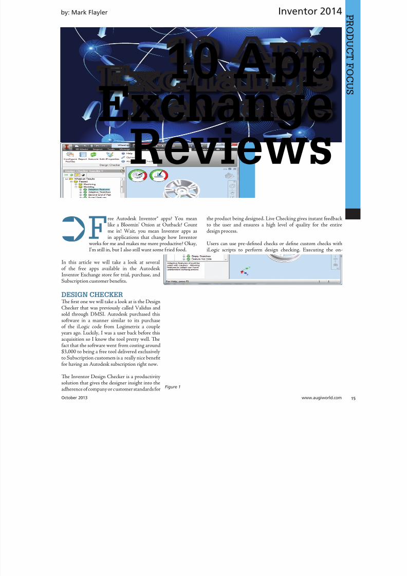
8122019 augi world 2013 10
httpslidepdfcomreaderfullaugi-world-2013-10 1552October 2013 wwwaugiworldcom
Inventor 2014by Mark Flayler
F
ree Autodesk Inventorreg apps You meanlike a Bloominrsquo Onion at Outback Countme in Wait you mean Inventor apps asin applications that change how Inventor
works for me and makes me more productive OkayIrsquom still in but I also still want some fried food
In this article we will take a look at severalof the free apps available in the AutodeskInventor Exchange store for trial purchase andSubscription customer benefits
DESIGN CHECKERTe first one we will take a look at is the DesignChecker that was previously called Validus and
sold through DMSI Autodesk purchased thissoftware in a manner similar to its purchaseof the iLogic code from Logimetrix a coupleyears ago Luckily I was a user back before thisacquisition so I know the tool pretty well Tefact that the software went from costing around$3000 to being a free tool delivered exclusivelyto Subscription customers is a really nice benefitfor having an Autodesk subscription right now
Te Inventor Design Checker is a productivitysolution that gives the designer insight into the
adherence of company or customer standards for
the product being designed Live Checking gives instant feedbackto the user and ensures a high level of quality for the entiredesign process
Users can use pre-defined checks or define custom checks withiLogic scripts to perform design checking Executing the on-
10 AppExchange
Reviews
Figure 1
8122019 augi world 2013 10
httpslidepdfcomreaderfullaugi-world-2013-10 1652wwwaugicom October 20
Inventor 2014
PRO
DUCT
FOCUS
demand checking updates the design checker results and enablingthe live-checking allows users to get the real-time feedback fromthe design checker during design process Te Design CheckerResults ree Browser allows users to interactively edit the objectswith failed checks and a Design Checker Results Report shows allthe passed and failed check results and allows users to export thereport to Excel Word or pdf or print the report
Now what I really enjoy about this tool is the iProperty checks andsome of the modeling checks Te machining checks I could livewithout mostly due to the fact that most companies try not to hireusers who make such drastic mistakes in machining operationsMy favorite thus far is the unconstrained sketches check thatvalidates my design before adding it to Vault I have also usedthis as a measuring stick before hiring new engineers or bringingvendor Inventor models into my design
AUTODESK REMOTETis next app allows some really nice RDP usefor Autodesk Inventor Autodesk Remote is astandalone application for Microsoft Window7 and 8 and is compatible with all Autodeskproducts It lets you drive Autodesk softwareinstalled on your primary computer from aremote computer or iPad for fast access to nativedesign data over standard networks o use itsimply install Autodesk Remote on the PC you
want to share Install it again on the machine youwant to connect from and start your connectionNote Autodesk Remote currently works only inNorth America
Autodesk Remote also has a companion applicationfor the iPad that allows you to access your hostPC from an iPad Te iPad app is optimized forAutodesk Inventor so you can work from anywhereimproving collaboration and increasing flexibilityDownlaod the iPad app from the Apple Store
Te controls in the iPad app are pretty easy to understand bthat doesnrsquot make a high-end CAD product made for the Pinstantly translatable to a touch interface You can see wheinterface elements of Inventor have started to lean more towarthis inevitable progression though
From my usage of the iPad app on my iPad 3 I found the usagelittle sluggish and gesturing a bit picky I found the use the ES
Figure 2
Figure 3
Figure 4
Figure 5
8122019 augi world 2013 10
httpslidepdfcomreaderfullaugi-world-2013-10 1752October 2013 wwwaugiworldcom
Inventor 2014
key a mandatory function as I often initiated one navigation tooland found myself trying to start something else before finishing thetool I was in In the end I see some fantastic usage on the horizonfor this app but right now it is pretty gimmicky for my taste I dopicture myself at some point on my front porch with my tabletinstead of my computer I would look cooler to the neighborhoodkids too
Be aware you will probably have to troubleshoot the setup of thisapp a bit I had to lock and unlock my computer and restart theapp several times before I got it just right
FEATURE RECOGNITIONTe Feature Recognition application converts neutral 3D CAD
models such as SEP SA or IGES solids into full-featuredAutodesk Inventor models Feature mapping could be executedautomatically or interactively as needed to maintain design intentCurrently there is one Automatic Feature Recognition commandand eight feature recognition commands you can use
Automatic Feature Recognition attempts to recognize specificfeature types and populate the browser tree with the recognizedfeatures A dialog box displays the feature types you can recognizein the Features section with the defaults checked You can selectfeatures you want to recognize and deselect features you do notwant to recognize
When you import a file it will offer to start feature recognition Ifyou decide to do it later you will have to find your Base1 solid inyour tree and right click on it to start it again
Tis tool has been around for a long time previously only on
Autodesk Labs Personally I donrsquot like it mainly because I have toconstrain and dimension the sketches when they get recognized bythe tool If your goal is to bring in a solid and then do some minormodifications to it then you are better off using the Edit Solidtools also shown in the image above If you want Work Plane toolsalso remember to turn off the Import into Repair Environment aswell before opening the file
If you really had to go the distance and recognize features it isactually a lot quicker and generally creates a more intelligentmodeling history if you just redo it yourself in Inventor Terecognition tools only lend themselves to simple parts inmost cases
Figure 6
Figure 7
Figure 8
Figure 9
8122019 augi world 2013 10
httpslidepdfcomreaderfullaugi-world-2013-10 1852wwwaugicom October 20
Inventor 2014
PRO
DUCT
FOCUS
WORK FEATURE VISIBILITYTis product allows Inventor users to manage all work featurevisibility in a fast and easy way keeping full awareness of the involvedentities Tis app consists of six buttons on part environment andanother six on assembly environment Inside of part environmenta user can choose to enable or disable the visibility property ofplanes axes or points Inside of assembly environment a user can
also choose on which components to enable or disable the visibilityproperty of planes axes or points
I had a little trouble with this app in the assembly environmentbut that was due to some bad installation files Tis is one appreally worth the $099 How often have you been in an assemblyand not wanted to go back to the part files to turn on and offwork features I recommend ungrouping them so you access bothcommands faster
SHEET METAL FLAT EXPORTTere seems to be a plethora of these apps on the Exchange witheach of them varying in price and options In general the ideabehind these apps is to help automate the process of getting a DXF
to a machine that reads them for manufacturing in a more efficientmanner Tese programs will scan an assembly file and find thesheet metal files on which to perform their routines
Te different variations of this program range from free trialsupwards of $100 for the paid apps I started with one that gave me
a ldquoliterdquo version that would do 20 sheet metal files and I liked it much I started using the full version
FEATURE MIGRATORTe Feature Migrator tool allows Inventor users to more eascreate part features from assembly features User can migraassembly features either by selecting them in the Feature Migratbrowser or by right-clicking on one or several of them and theusing the ldquoSend to Partsrdquo commands Features can also be directmigrated from the regular Inventor model browser using thcontext menu item added by the add-in
Once the operation of migrating features is completed the FeatuMigrator displays a dialog that provides information about thresults Tis first dialog is a ldquohigh-levelrdquo report of the migrationprovides the opportunity for the user to select the action to takfor all the assembly features migrated Suppress if SucceedeSuppress always Delete if Succeeded Delete always or Nothingalso for the part features that havenrsquot been migrated correctSuppress Delete or Nothing Features created by the add-in cbe in an invalid state in the parts for a number of reasons
Te user can also see when a feature is out of date from thassembly and perform updates from the part side
Figure 10
Figure 11
Figure 12
8122019 augi world 2013 10
httpslidepdfcomreaderfullaugi-world-2013-10 1952
8122019 augi world 2013 10
httpslidepdfcomreaderfullaugi-world-2013-10 2052wwwaugicom October 20
Inventor 2014
PRO
DUCT
FOCUS
TIME STAMPime Stamp is an Autodesk Inventor add-in that provides bull A low-cost simple-to-use tool that adds plot time information
to your printsbull A plot stamp that does not dirty the Inventor drawing
documentbull
A simple dockable user interface that keeps out of the way
Te ime Stamp editor lets you size position and orient thestamp relative to the adjacent sheet edges You can include datetime and current user information in the stamp Te time stamponly appears on the plot it does not alter the Inventor drawing
What I really like about this app even though it costs $500 perlicense is that you can find the price yourself and buy it It doeseverything it says it does and it provides an easy-to-use interfacewith an icon that changes based on whether the tool is on or offIf you want even more control over your plot stamping there is amore professional version offered by this company on their websitefor about $4000 a license which will allow more reporting fieldsand more control on the look and location of the stamp
SIMPLE SHEET SETTINGSSimple Sheet Settings combines the existing sheet settings withsome new tools such as changing the title block and also the abilityto make changes to all sheets in a document at once
Instead of first deleting the existing title block from a sheetexpanding the title block folder and inserting the desired titleblock then opening another window to change the sheet size andorientation just click the ldquoSettingsrdquo button located on the Sheetspanel in the Placed Views tab (right next to ldquoNew Sheetrdquo) andhave access to all those options in one location
When the Simple Sheet Settings window is loaded it gathers all the existing title block names and puts them into one drop-dowmenu o change the title block on the current sheet simply selethe desired title block from the drop-down menu and click OKTere is also the ability to change the title block sheet size ansheet orientation to all sheets at one time
Tis is a great little app that saves clicks and only costs a dollaQuite useful and no real setup involved
INTERACTIVE TUTORIALTe Create an Interactive utorial app provides instructions fcreating your own interactive Inventor tutorial Te Guide alincludes how to customize the Welcome Screen to display yointeractive tutorial and add to the ribbon
Tis one definitely falls under the ldquotoo much time on your handuser or CAD admin After reading through the guide on how create the interactive tutorials you find yourself asking the questioldquoWhy donrsquot I just save videos of the process we use in a companserver locationrdquo And that is when you uninstall this app as yohave realized that while it sounded good to you at first there abetter ways to accomplish the goal of company-specific tutoria
and process documentation
Figure 16
Figure 17
8122019 augi world 2013 10
httpslidepdfcomreaderfullaugi-world-2013-10 2152October 2013 wwwaugiworldcom
Inventor 2014
Te tools actually rely on too much externally controlled softwaresuch as Camtasia and other plug-ins and third-party apps to makeit work correctly Save your time and just use Camtasia from
echsmith to do your bidding
KEEPING UP TO DATEWith all these apps it is easy to understand how a user could getbehind on the updates to so many tools With that in mind theExchange Manager found on the ools tab in Inventor will keeptrack of that for you and offer assistance not only in updating butalso uninstalling and specialized help for each app
As a reminder with regard to third-party apps if you startexperiencing undesired effects in Inventor start turning add-ins
off one by one until you isolate which one is giving you fits Properreporting back on the app to the developers makes everyonehappier when the issue gets resolved Tus far I havenrsquot had nearas many issues as I thought I would have
ANY MANY MOREWith 80+ apps currently in the store and about 60 of them ready
for 2014 at the time of this article you should take some time andlook through what is available Tere are apps which are very nicheto the user base as well as those that have you scratching your headover why they are not already part of the core software Below aresome I would write about if I had more room in the article andora fatter PayPal walletbull BOM oolsbull EDM Expressbull Sketch Symbol Librarybull SolidWorks iProperty Importbull Quick Viewsbull 3D Pipebull Point Linkerbull Kwikools
Mark Flayler is an application engi-neer with IMAGINi echnologiesspecializing in manufacturing environ-ments He has implemented Autodeskmanufacturing products within severalindustries including the blowinjectionmolding automotive and custom ma-chinery markets When not providingtraining support and implementationhe writes the IMAGINi Manufac-turing Blog and takes an active role inthe manufacturing community Markis an AC certified instructor and isPSE and AC certified in AutoCADAutoCAD Mechanical AutoCADElectrical Autodesk Data Manage-ment and Autodesk Inventor
Figure 18
Figure 19
8122019 augi world 2013 10
httpslidepdfcomreaderfullaugi-world-2013-10 2252wwwaugicom October 20
SPECIALFEATUREAUGI Forums by Melanie Perr
The AUGI Forums are as always a busyplace Ask a question and you mightsee half a dozen varied methods andworkarounds posted in a single thread If
you have not had any questions yourself I would stilllike to encourage you to pop into the Forums and see
if there are any problems you could solve especially if you use one
of the less adopted products Tere will always be many helpinghands in the AutoCAD and Revit Forums but what about themechanical products or design visualization or structural detailingForums Peek in and see if you can share your experiences andwisdom with the community
I confess that I only scoured the English-speaking Forums forcontent for this article but please keep in mind that there areAUGI Forums available in 12 other languages so users have theoption of asking for support in their native tongue
AUTOCAD ndash SYSTEM VARIABLE
DISCUSSIONhttpbitly15M1hB9
Tis topic started out when a user couldnrsquot delete Te solution wasultimately the PICKFIRS variable but the discussion evolved tosafeguarding other variables automatically just to protect against aloss of settings in the event of a crash User Coloradomrg offeredthe safeguard shown in figure 1
Norton_cad also suggestsDIMLFAC EXPER andBLIPMODE be addedto the list
REVIT ndash
UNDERLAY
BEHAVIOR
EXPLAINEDhttpbitly15M1iFd
Mschroeder opened thediscussion with If you haveever wondered why some wallsdonrsquot show up in underlays or
show up inconsistently from floor to floor or why roofs and vieranges affect their behavior then read on
First rule of underlays Underlay view extent properties (cut rangdepth) are not user modifiable and not coupled to any othviewrsquos properties
Itrsquos also been mentioned ldquoIf objects are visible in the view ranof your current view AND in the view range of your Underlathey are automatically hidden in your underlay so there isnrsquotdouble instancerdquo
Users twiceroadsfool and dbaldacchino helped clarify the effecby posting sample models and pertinent data from the AutodeKnowledgebase and Autodesk Support Visibility View RangDetail Level and Cut Planes are all touched on in this discussioNeed clarity on how to make the most of Underlays Check inthis thread on the Forums
LISP ndash MAKING A DIALOG BOX RETAIN
ITS SELECTIONShttpbitly15JzMCc
Te LISP Forum always has such fascinating topics it is hato decide which to highlight From locking OSNAP options setting Explode options along with troubleshooting of existincode But the discussion surrounding the tutorials and metho
to retain selectioin a dialog box wvaried and lively so had to check it ou r e a v e s 0 4 4 1 3 2 1
even posted a sampdcl file when he wfinished
String Theory
8122019 augi world 2013 10
httpslidepdfcomreaderfullaugi-world-2013-10 2352October 2013 wwwaugiworldcom
AUGI Forums
AUTOCAD ELECTRICAL ndash LINES BEING
LABELED AS WIREShttpbitly1ew9p9D
Dinochrome says that one of his coworkers has reported aproblem with regular AutoCAD lines being labeled as wires
Crosswire35 advises ry checking your wire type edit dialogbox and make sure the ldquomake all lines valid wiresrdquo checkbox is unchecked
And IMCO goes on to say Using the vanilla line command inACADE will still place that line on a wire layer Change your linesto layer 0 and ACADE will not give them a wire number
AUTOCAD STRUCTURAL DETAILING ndash
TUTORIALShttpbitly17kW7cc
Te consensus is that this product is a little confusing to figure outand that most of the tutorials out there are older Most productshave a few videos floating around on Youube but this one doesnot seem to have too many yet
Jpo82 chimes in with I guess only tutorials forthis software are those found at Autodesk websiteTey are for versions 2010 and 2011 but still validhttpusaautodeskcomadskservlet12ampid=13111928 Irsquom not sure but sometimes I feel that the only new feature inASD 2013 is that itrsquos more stable than previous releases
Lucis29 goes on to say Also you might check some movieshttpwwwrobotofficecomasd but they are very old
Spenner then linked to his reporting of the Service Pack andissues it addressed hoping that it addressed some of the issuesthat came up in this discussion
NAVISWORKS ndash IMPROVE ANIMATION
EXPORT QUALITYhttpbitly1fQLoIv
Different methods are discussed from exporting individual imageframes to exporting a video (and how long) but I will leave youwith the following list from Revit For Breakfast
Here are the secrets to movies in Navisworks1 Donrsquot use materials ndash you make your render time much longer2 Use the PNG export option 15fps3 Make your video export twice as long as you need Ten speed it
up for a faux 30fps Tis is faster4 Look up the Navisworks blog by Lee Mullin and Paul Walker
about gooch and phong Tere is your faux render setting5 If you have NW 2012 you wonrsquot have gooch or phong but you
will have better export options 2013 has gooch and Phong butfewer export options
6 Te flickering occurs when multiple shapes overlap If you care
delete them in your export model Sometimes flickering occurs
in the generation of your frames on the PNG export You mayhave a frame that is ldquooffrdquo
7 Set your anti-aliasing to 4x or better on the png export8 Check out my old post httpforumsaugicomshowthread
php132209-Animation-Resolutionampp=1138298ampviewfull=1post1138298
CAD MANAGEMENT ndash NETWORK DRIVE
CHANGED BY IT WITHOUT WARNINGhttpbitly18J4k9c
Blackbox advises edinsmore595165 straight off to utilize theReference Manager program that comes with AutoCAD inorder to reconnect all of the external reference paths that werebroken when the I department upgraded their archaic serversHe further points out that moving from hard pathing to relativepathing would make things easier in the future
Feargt offers another twist Another option which would workon a need only basis when you open the specific drawing Change
XREF and Image paths in drawing to Network path throughscript on a need only basis Basically this will only change pathsPlace this line in a acaddoclsp file(command ldquoscriptrdquo ldquoyourserver and pathXREFREDIRECscrrdquo)and the following in a script fileREDIRB enter name of path to be replacedP enter new path
Tere was also a debate in this thread about obstacles and benefitsof user-managed and I-managed drive mapping
Melanie Perry is a Facilites-Manage-ment Coordinator and echnical Edi-tor in St Louis MO She is the AUGISalary Survey Manager and is curring-ly serving as an Officer on the Board ofDirectors Melanie can be reached atmistressofthedorknessgmailcomor found on witter asMistresDorkness
OTHER HOT TOPICSHave you found a Forum solution so mind-bogglinglyuseful that you leapt out of your chair with a whoopingcheer (or were at least tempted to) Please let me know Asingle person cannot read every post in our bustling AUGIForums so if you would like to see a thread highlighted ina future edition of String Teory feel free to let me knowSend me Wanderer a PM in the Forums or send an emailto MelaniePerryaugicom
See you on the Forums
8122019 augi world 2013 10
httpslidepdfcomreaderfullaugi-world-2013-10 2452wwwaugicom October 20
Revit Architecture 2014
PRO
DUCT
FOCUS
by Martijn de Rie
Myth Buster
Revit amp IFCPart 3
Irsquove given a lot of thought as to how this trilogyof articles should end At first I thought Irsquoduse the Coordination View 20 EXPRESS-GWallPaper for IFC2x3 (httpwwwmdr-
adviesnlwp-contentuploadsCoordinationView_V2-0_WallPaper_IFC2X3_Version-1pdf ) as a stepping stoneto give an ldquoIFC for Dummiesrdquo type of solution But that turnedout to be quite lengthy and rather boring But the link is includedabove for obvious reasonsmdashitrsquos useful
So I went back a little and asked myself ldquoWhy IFCrdquo And with thatquestion the inevitable follow-up immediately appeared ldquoWhynot IFCrdquo I realized that in the previous articles I failed to explainwhy in my humble opinion we should care about this somewhatcrooked badly implemented severe headache-inducing formatTerefore instead of explaining the fundamental technicalities ofIFC that can be explored in other places this final installment willexplore the Why versus Why Not IFC discussion and begin withthe latter
WHY NOT IFCWhen everybody uses Autodeskreg RevitregWell in this case itrsquos a no-brainer Share your Revit files Period
Loss of dataTis is an easier way to share data instead of hacking your wthrough IFC and praying your stuff doesnrsquot get lost in the proce
Even when you manage to export your geometry through IFtherersquos always loss of data
Loss of intelligence during importEven if you only need to send over geometry not data importithat into Revit makes it utterly useless All constraints are locomponent parametrics are gone and so on
Availability of bidirectional linksWhen not everyone uses Revit on a given project (which is quoften when yoursquore not located in the US) why not simply ua bidirectional linking between proprietary software standardTis can be easier and better to control
8122019 augi world 2013 10
httpslidepdfcomreaderfullaugi-world-2013-10 2552October 2013 wwwaugiworldcom
Revit Architecture 2014
WHY IFCWhich may be asked as why would you want to use IFC Or moreaccurately why would you want that option available
Consider what Sir Arthur Conan Doyle wrote ldquoOnce you eliminatethe impossible whatever remains no matter how improbablemust be the truthrdquo
Letrsquos put that to the test shall we
When everybody uses RevitOkay simple math Autodesk has around 7000 employees Teworld has about 72 billion people What are the chances someonenot working for Autodesk has a brilliant idea and creates thesoftware you need tomorrow Tere will always be better solutionsTey might not be viable for you overall but therersquos no reason toshut down access to them Revit is a wonderful generic tool forwhich I see a brilliant future with all kinds of additions for specificniche-markets like AutoCAD has
What about today DDS is MEP-engineering software that cando energy calculations (not simulations) inside your modelRhino lets you model things on the fly that could (arguably)take ages in Revitmdashif you ever get them done ekla lays wasteto the Revit structural rebar functionality any day of the weekwithout breaking a sweat Solibri is a wonderful solution for clashdetection and most importantly rule-based model checking andreportingmdashsomething Revit (or Navisworks) doesnrsquot do
Should I go on
Only problem for all this magnificent software Itrsquos either based onthe IFC format or requires model exchange through IFC
Te fact of the matter is there will always be better softwareAny one may be the software for you but that doesnrsquot mean yourpartners associates etc need to have the choice to use it forcedupon them
Loss of dataOn July 1 2013 there was an extra release for Autodesk softwareTe Sourceforge Open Source IFC Exporter released a new versionthat incorporated the option to map custom Revit parameters(shared or non-shared family or project even calculated values) totheir IFC counterparts
On September 28 2013 I had the honor of showing the secondstep in a complete and controllable data export from Revit
During my RC Europe class I showed the new option to create acustom IFC Property Set and map any given Revit parameter intoIFC fully customizable
IFC does not automatically lead to loss of data Tat idea is simplynot true Incomplete implementation in Revit does lead to loss ofdata As of now you are able to put any piece of data into an IFCeven calculated values And we didnrsquot change the IFC format We
just improved implementation in Revit
Loss of intelligence during importldquoJust because something hasnrsquot happened yet doesnrsquot meanitrsquos impossiblerdquo
I donrsquot know who originally had this insight and I doubt it to bethe movie line I remember but it is true
In the same RC Europe class I showed a native Revit familybeing exported to IFC altered and re-importedmdashwhile keepingall parametric constraints and even adjusting to the alterationsmade directly in the IFC file It is possible but not with thecurrent importer
Availability of bidirectional linksIrsquove been using Revit for almost 10 years now For 4-5 years I didnrsquotknow about IFC at all Before a year ago this was my strongestargument against IFC Why would you need a generic ldquolanguagerdquowith all its limitations (of which there are) weaker implementationand use of parametric capabilities (because it has) and lag-times indevelopment (by nature)
IFC will never be able to do what native software does simplybecause itrsquos responsive in nature Development budgets are afraction of what Autodesk rimble or Nemetschek get to spendon their software
So why not keep it simple and use a bidirectional link Revit has itwith a lot of other Autodesk software and third-party applications
But how long have we waited for them And are they even trulybidirectional Do they exactly do what you want them to do In myhumble opinion the answer to these questions is not very inspiringEven bidirectional links tend to have major limitations and severe
constraints in flexibility And most important Te link itself isalso propriety software No way of adjusting it to your needs
WHAT IF MORE PEOPLE STOPPED
TALKING ABOUT IT AND JUST GOT
INVOLVEDTe improbableFirst off itrsquos a matter of simple logic As Sir Arthur suggested ifwe can successfully check off all likely options to NO want touse IFC doesnrsquot that mean the improbable is true Tat IFC is infact a valuable tool in our toolkit and we should be able to use it
when necessary
Mind you Irsquom not saying you should use IFC If yoursquore on a Revit-only project it would be insane Just send and receive RVs Tefact is this will only be viable for limited parts of the buildinglifecycle If yoursquore lucky the entire design team is on Revit Butmanufacturers have other software facility managers too
As for the design team what if the best structural engineer is not[on Revit] or the MEP guy that has loads of experience in similarprojects Would you settle for second-best just because someoneuses the same brand of tools you do I wouldnrsquot
8122019 augi world 2013 10
httpslidepdfcomreaderfullaugi-world-2013-10 2652wwwaugicom October 20
PRO
DUCT
FOCUS
Revit Architecture 2013
Open AccessWhich brings us to the biggest advantage of IFC (or any open
format) itrsquos open Which means itrsquos adjustable to your needs Nowdonrsquot go ldquothatrsquos too difficult expensiverdquo Tatrsquos bullocks
Te first external enhancement to the Open Source Exporter wascreated by om Pesman a self-employed API specialist
Parametric IFCImplemented by Jon Mirtschin also self-employed IFCparametrics is available Agreed Jon is a well-known IFC guru butstill the point holds
Custom property sets and parametersWim as owner of a small MEP engineering firm hasadded functionalities toward this end and hersquos not even a trueAPI specialist
All these developments were done for free by altruistic volunteerefforts as part of the creation of the Dutch Revit Standards Andof course with the invaluable help of the Autodesk Open SourceIFC Exporter team Angel Velez in particular
But what if these guys actually got paid What if this projectwasnrsquot a Saturday night side-job What if more people stoppedtalking about it and just got involvedmdasheither by themselves or byleveraging experts to get what is needed Te entire IFC format is
Open Source the source code is out there which basically meansyou can do whatever you want and create whatever you needmdasheven on a project-by-project basis
BIM ITrsquoS THE ldquoIrdquo THAT MATTERSIn my humble opinion the entire debate on BIM is focusing on thewrong part of the acronym I donrsquot care if ldquoBuildingrdquo is a noun ora verb Nor do I care whether itrsquos ldquoModelrdquo or ldquoModelingrdquo nor am Icommenting on whether one should say ldquoBIM Modelrdquo
Itrsquos the ldquoIrdquo that matters If wersquore collaborating the Informationis most all I care about I just want your datamdashin the leanest
smartest and most effective way possible
A Revit model will do conversely a lot of times A Revit model w
give me heaps of data I donrsquot want geometry I donrsquot care about ana file format I canrsquot use Now we can all keep on being really anabout it or we can simply use the tools available to us one of thebeing IFC
A FINAL NOTEAs stated at the beginning of the article I really enjoyed writinthis series and for now this is the last of the series But if yoursquointerested in more tips and tricks on IFC let me know I might able to persuade the guys at AUGI to let me write about it againLord knows there is still a lot to talk about regarding IFC
Martijn de Riet is a self-employedBIM Consultant from the Nether-lands working with Revit since version51 Martijn has a bachelor degree inBuilding Science After his studieshe started his own engineering firmworking for contractors architects and
private clients Starting in 2007 hiscompany transformed into a full-timeBIM consultancy service At the mo-ment Martijnrsquos clients vary from mid-sized architectural firms to the largest
dutch General Contracter and MEPEngineering firms with a focus onspecific corporate solutions design andimplementations of Revit and BIMworkflows Martijn is a member ofthe Dutch Revit User Group and cur-rently working on creating a Masteremplate and Component LibraryHe provides lectures for companiestechnical universities seminars etc ona regular basis
Itrsquos the ldquoIrdquo that matters If wersquore collaborating the Information is most all I care about I justwant your datamdashin the leanest smartest and
most effective way possible
8122019 augi world 2013 10
httpslidepdfcomreaderfullaugi-world-2013-10 2752
wwwxicomputercom
8122019 augi world 2013 10
httpslidepdfcomreaderfullaugi-world-2013-10 2852wwwaugicom October 20
3ds Max 2014
PRO
DUCT
FOCUS
by Chris Murra
SUMMARY WHATrsquoS
CUSTOMIZABLE IN MAX
(HIGH LEVEL)When it comes to the customizability of Autodesk 3ds Maxregitrsquos no secret that it can morph itself into whatever you want theprogram to become
Whether yoursquore a modeler animator lighter rigger generalist ortechnical artist 3ds Max can become your own personalized toolbox that is an extension of your own hand in your daily workYou can now combine different command types (such as creatingobjects and object modifiers) into a single menu reducing themouse travel and improving efficiency
In this article wersquore going to take a closer look at one specificaspect of customization with 3ds Max the new enhanced UI Aspart of this article besides taking a deep dive into the operationof this feature I will also be showing how I created the ldquoMographrdquo
tools UI that includes custom buttons and icons At the end this article I will also provide a link to this UI so you can use customize it yourself or share it with others
ENHANCED UI SUMMARYWhat is the Enhanced UI
Te Enhanced UI is a new graphical user interface system thdoes two main things
1) It provides a refreshed 3ds Max user interface with updattool categories and new clusters of pre-existing tools in groupinthat are more akin to their intended purpose as opposed to somtechnical requirement for menu placement
2) It provides a way to allow you the end user to customize thmenu system in almost any way you choose Te drop-down menare ldquotear-ablerdquo (not to be confused with ldquoterriblerdquohellip but I digresand the resulting configurations are savable either by scene or
3ds MaxEssentialsCustomizing
the UI
8122019 augi world 2013 10
httpslidepdfcomreaderfullaugi-world-2013-10 2952October 2013 wwwaugiworldcom
3ds Max 2014
a preset Tey are also distributable and deployable so they can beshared with others
Where is the Enhanced UITe Enhanced UI can be found in the upper left hand corner of themain UI at the very top of the screen Tere is a drop-down menuthat says ldquoWorkspace Defaultrdquo Tis default is the same baselineUI that ships with all 3ds Max installs (Figure 1)
Within the drop-down you can find the ldquoDefault with EnhancedMenusrdquo Tis is the alternative default menu system that youcan use on its own or use as a starting point to create your owncustomized menus
BASIC DEFAULT CUSTOMIZATIONEnhanced UI Customization BasicsNow that wersquove enabled the Enhanced UI how can we change it
SOP Before you begin mucking around with the UI Itrsquos importantto understand what I call the ldquosave-logicrdquo as it pertains to custom UIs
Te UI Save LogicIf you plan on saving this UI for future use there is a specificmethod you must follow to properly save the UI you want and notwreck the default Enhanced UI
Te Save Logic is as follows Itrsquos simple but important
Step 1 urn on Enhanced Default UI (Figure 3)
Step 2 Click ldquoSave as New Workspacerdquo FIRS At this point youwill be prompted for a new name (Figure 4)
Step 3 Edit and change the UI at will
NOE All future edits are ldquoautomatically rememberedrdquo as you go (Iintentionally did not use the word ldquosaverdquo)
Step 4 Te ldquosave as default staterdquo button is important When wehave completed the customization process we then choose thisbutton to ldquolockrdquo in the changes Tis is different than Saving a UIwith a custom name
HO IP ldquoBut this methodology seems backwardrdquo
I can see how yoursquod say that but remember that any changes you make
to any enhanced UI are automatically ldquorememberedrdquo If you create acustom UI then while working you make some temporary changeswhen doing something specific those little changes are automaticallyremembered If you want to return to the default state [of yourcustomized UI] you select ldquoReset to default staterdquo Tis does NObring back the default Max UI rather it brings back the customizedUI you created in ldquolockedrdquo in Step 4
Okay now that you have the save logic down letrsquos begin customizing
1) If you havenrsquot done so already turn on the Default Enhanced UI
2) Go to ldquoManage workspacesrdquo from the drop-down and in the
Figure 1 Workspaces are in the Workspace drop-down menu
Figure 2 Default UI (left) and the Default Enhanced UI (right)
Figure 4 Saving the New UI Workspace
Figure 3 Turning on the Enhanced Default UI
8122019 augi world 2013 10
httpslidepdfcomreaderfullaugi-world-2013-10 3052wwwaugicom October 20
3ds Max 2014
PRO
DUCT
FOCUS
Manage workspaces dialog choose ldquoSave as new Workspacerdquo Giveit a specific name
3) Begin making your desired changes
Since a custom UI is specific to any one individual letrsquos take a lookat what types of customizations can be made
Simple ChangesOne of the simplest things to do is peel off any commandgroup (see Figure 5) Just click the group title bar and drag Tecommand group becomes a floating dialog box Now just becauseyoursquove peeled it off does not mean that yoursquove removed it fromthe drop-down menu Te ldquooriginalrdquo command group remains inthe drop-down You can just close the floating dialog when yoursquoredone with it
Probably the simplest thing you can do is reorganize the menusIn each drop-down menu appears a group of commands You maynotice that some command groups are icons and some are words(Figure 6) o change the appearance of the commands there is asmall icon in the upper right corner of each group of commands(Figure 7)
Te next change is alreally simple Is tcommand group op(expanded) or clos(rolled up) Just clion the plus or minsign in the upper le
corner to set this stafor the next time yolaunch 3ds Max (Figu8) Remember thesettings are saved as yogo so whether it is opor closed is your choicbut the state the menis in when you cloMax is the one that remembered the netime Max opens
What about Saving tDefault state More othis later
Once you have floating menu yocan combine differecommand groups dragging any othcommand group to aother floating dial
that yoursquove created Tis makes for easy creation of custom dialo
based on specific tasks Figure 9 shows a command group fcharacter animationFigure 5 A floating menu that has been torn off the drop-downmenu
Figure 6 The different display states of the menus
Figure 7 Changing menu layouts
Figure 8 Rollouts
8122019 augi world 2013 10
httpslidepdfcomreaderfullaugi-world-2013-10 3152October 2013 wwwaugiworldcom
3ds Max 2014
ADVANCED CUSTOMIZATION
What about completely custom interfaces Herersquos how we do thatwith the Enhanced UI menu system
Te following is the high-level overview of the process Wersquoll thenunpack each step in more detail
If you havenrsquot read the section on Basic default customizationplease do so before continuing Before starting this phase ofcreating your new UI you should have saved your new UI stateTat process is explained in the previous section
1) Create a main drop-down menu (like ldquoMy oolsrdquo)
2) Create a tools category menu into which you will place yourtools (a submenu such as ldquoModeling oolsrdquo or ldquoAnimation oolsrdquo)Drop-downs can have more than one subcategory
3) Add commands to various submenus
4) Clean up the UI by creating custom names adding separatorsor creating custom icons
First letrsquos create a new menu for the menu bar Tis is done easilyfrom the CustomizegtCustomize [Rollout]gtCustomize UserInterface dialog box
Steps for Creating a Drop-Down Menu1) Create a New Menu and give it a name (see Figure 10)
2) Locate your new menu in the Menus window It will be listedalphabetically (Figure 11)
Figure 9 Multiple command groups in one menu
Figure 10 ndash Creating a new drop down menu
Figure 11 Location of new menu
8122019 augi world 2013 10
httpslidepdfcomreaderfullaugi-world-2013-10 3252wwwaugicom October 20
3ds Max 2014
PRO
DUCT
FOCUS
3) Drag your newly created menu category over to the column onthe right Tis will add your new drop-down menu to the interfaceimmediately and you can begin populating it with menu items (seeFigure 12)
UI DESIGN IP Te actual menu name and display name can bedifferent I used a custom menu name behind the scenes so I couldeasily differentiate my menus from the ones created by default or other
tool companies After you create a menu and add it to the right column you can right-click on it and change its display name (see Figure 13)
Next letrsquos create a command group1) Just like in Step 1 from the previous section create a new men
2) Tis time before you drag it to the right column click thplus sign next to your drop-down menu item to expand it Tedrag the new item to the right column dropping it ldquounderrdquo thmenu name
3) Drag any commands from the Commands window on the leto the submenu on the right (see Figure 15)
Herersquos an example from my Mograph ools workspace thshows how a completed menu looks once it is created (Figu16) In the following figure you see both the menu as it appeain the Customize UI dialog and the actual menu (which has bepeeled off)
Notice that some of the commands on the menu are greyed ouTatrsquos because this new menu combines both ldquoObject creatcommands and ldquoObject Modify Commandsrdquo in one menTey will remain grey until you create an object on which thwill be used
Figure 12 Adding the new menu to the UI
Figure 14 Creating a command group
Figure 15 Dragging commands onto the menu
Figure 13 Custom menu names
8122019 augi world 2013 10
httpslidepdfcomreaderfullaugi-world-2013-10 3352October 2013 wwwaugiworldcom
3ds Max 2014
Adding SeparatorsSeparating commands is easy and is recommended to help you oryour intended user make sense of the how the tools are arranged inthe menu Creating a separator is as easy as dragging one over theright column just like a menu or command
HO IP ldquoWhy do I need to create another menu Why canrsquot I addtools right to my menurdquo
Te main reason is that adding a submenu gives you the ability to tearoff the submenu If it werenrsquot in a submenu it wouldnrsquot be tear-ableSo itrsquos really a ldquobest practicesrdquo kind of thing But even if you try to notadd the submenu it will happen automatically Itrsquos important to do it
explicitly so you are aware of what submenus are in the menu and that you are the one in control of what command is going where
CUSTOM ICONSNo custom UI is complete without a custom set of iconsAdditionally not all commands in 3ds Max have their own iconyet But itrsquos important to realize that regardless of how you set up
your UI yoursquore still working within the framework of an existingapplication and there are boundaries to what you can edit andcreate Icons have specific requirements both in their creation(size) location and file name that must be adhered to in order forthem to work properly
SizeformatTe size of icon is pretty simple It must be 32x32 pixels andPNG format
LocationTe location is very specific New icons must be added to thislocation
CProgram FilesAutodesk3ds Max 2014UI_lnResourcesDarkIconsMain
Te new icons I created for the Mograph UI are shown inFigure 17)
Icon File NameIf yoursquore still with me at this point we are now getting into thenether regions of customizing a UI Tis is where things get a littletricky but itrsquos really not too bad File names are specific and aregenerated by the application (3ds Max)
So letrsquos begin First identify the command for which you want aniconmdashusually itrsquos one that doesnrsquot already have an icon But if itdoes and yoursquore changing it MAKE A BACK UP of the originalicon PNG file Tis is because as previously stated you donrsquot havecontrol over the file name Tat means if yoursquore creating your ownicon you need to overwrite the existing one and use its name foryour new icon So back up any original icons
Figure 16 The completed menu
Figure 17 ndash The created icons
8122019 augi world 2013 10
httpslidepdfcomreaderfullaugi-world-2013-10 3452wwwaugicom October 20
3ds Max 2014
PRO
DUCT
FOCUS
It really doesnrsquot matter whether you make the icon first or not ofind the name you need to use you need to navigate as follows
NOE Yoursquore about to edit the ribbon Tere is no need to save thesechanges as we are merely extracting information from it But if yoursquoredoing a lot of custom icon work you may want to save this change to theribbon so you can come back and continue your work in later sessionswithout have to recreate this every time just to get the proper file nameSaving this ribbon is not related to saving your default state of yourUI When yoursquore done creating all your UI icons you can just delete
whatever changes you make to the ribbon
1) Open the ldquoCustomize Ribbonrdquo dialog box
2) Create a new ldquotabrdquo by dragging it onto the ldquoExisting Ucolumn in the middle (see Figure 18)
3) Using the same drag method add a new ldquopanelrdquo to ttemp tab (Figure 19)
4) Now you can get the information you need Find tcommand for which you are creating an icon and dragto the panel
5) Locate the ldquoinfordquo portion of the ldquoPreview Windocolumn At the bottom of the column is the file namneeded to have the icon used properly by the applicati(Figure 20)
CONCLUSIONSo now you know how to create a custom UI scheme f3ds Max 2014 and up By using the Enhanced UI me
system itrsquos really easy to generate a multitude of workspathat allow Max to work the way you want to work
Te example used in this article was the ldquoMographrdquo UI thI created for NAB 2013 If you would like to downloand install it you can get it from my ldquoPinning the Stacblog on the Area herehttpareaautodeskcomblogschrismurray
Enjoy
Chris Murray works for Autodesk
Media amp Entertainment He istrained as an animator (3D variety)but considers himself a creative tech-nologist His daily role is a technicalldquoevangelistrdquo for Autodesk creating marketing deliverables for 3ds Max Heis the author of Mastering 3D StudioMax He has a Masters in Fine Arts(MFA) in Computer Animation fromMiami International University of Artand Design Follow him on witterchrismmurray
Figure 18 Creating a tab on the ribbon
Figure 19 Adding a panel to the tab
Figure 20 Finding the required file name
8122019 augi world 2013 10
httpslidepdfcomreaderfullaugi-world-2013-10 3552
AUGIMembersReach Higherwith ExpandedBenefitsAUGI is introducing three new Membership levelsthat will bring you more benefits than ever beforeEach level will bring you more content and expertiseto share with fellow members plus provide anexpanded more interactive website publicationaccess and much more
MEMBERMEMBER MEMBER
Basic members haveaccess tobull Forums
bullHotNews (last 12 months)
bull AUGIWorld (last 12 months)
DUES Free
Premier members haveaccess tobull Forums
bullHotNews (last 24 months)
bull AUGIWorld (last 24 months)
DUES $25
Professional members haveaccess tobull Forums
bullHotNews (full access)
bull AUGIWorld (full access and in print)
bull ADN 2013 Standard Membership Offer
DUES $100
Are you ready to upgrade yourself and your membership
Access additional benefits and upgrade at wwwaugicom
8122019 augi world 2013 10
httpslidepdfcomreaderfullaugi-world-2013-10 3652wwwaugicom October 20
AutoCAD MEP 2013
PRO
DUCT
FOCUS
by Vladimir Triantafillid
BIM IsWhatrsquos
Driving theIndustry
For the past decade many would arguethat building information modeling(BIM) has metastasized aggressivelythroughout the AEC industry but what
does BIM really mean More importantly whatdoes it do for us and for our industry Ask someone who hasbeen in this industry for more than 25 years or those nearingretirement and yoursquoll find that less than half see its value muchless care to make the effort with its implementation hesequestions mean something different for those who have beenin the industry the past 10-15 years Recent college graduates
however with their tech-savvy capacity and high expectationare eager to implement anything that resembles cutting-edgflashy technology ypical ly they are the ones most receptivenot adamant about putting their talents to use through BIM
I recently gave a BIM presentation with an emphasis on mchanical systems to the summer interns and new hires our companymdashall were non-BIM users except for onemdashbmy presentation did little justice to BIM Half of my audence had found a cure for their insomnia when they realizthis wasnrsquot the latest edition of ldquoCall of Dutyrdquo hat was n
8122019 augi world 2013 10
httpslidepdfcomreaderfullaugi-world-2013-10 3752October 2013 wwwaugiworldcom
AutoCAD MEP 2013
reflection on BIM by any measure Simply put I fell shortof connecting with a potentially captive audience eager toknow what really makes BIM intriguing or how it wouldgive them an edge in the industry I didnrsquot think to look pastpresenting the facts of its processes and benefits o simplyhave stated that proficiency in any of its many facets willpromote a lucrative career would give those still awake theimpetus to jump ship In hindsight the first step I shouldhave taken to begin this presentation was to ask what theywanted to get out of BIM
If you think itrsquos hard conveying the value and splendor ofBIM to receptive and impressionable young minds try toconvince the weathered veterans dead-set in their ldquooldtricksrdquo For every experienced veteran who has converted toBIM there are two ldquoold dogsrdquo that canrsquot shake ldquothe good olrsquodays when we used vellum and light tablesrdquo Guess whatmdashanincreasing amount of naysayers are starting to come aroundincluding those who say theyrsquove been burned by BIM in thepast hey are seeing the simple solutions BIM presents and
how these solutions translate into cost savings More andmore of those who had formerly questioned BIMrsquos utility areconvinced when installation efficiencies are not only real-ized but quantified
Another factor in the evolution of BIM is its tendency toexpand faster than the pace of its general population of us-ers hose of us proud to be catching up to what we think iscutting edge quickly realize it was just another false sense ofaccomplishment as BIMrsquos web continues to grow exponen-tially he solution is rather simple Focus on what you canhandle and always have the presence of mind and sense ofcaution to avoid being overwhelmed by the wake of BIMrsquos
progress herersquos plenty of money to be made and countlessfacets to explore as long we have the following mentality Welive in the information age and those wi lling to share knowl-edge will reap the rewards of communal synergy
On the opposite end of the spectrum you might find ourindustryrsquos opportunists In a hurried frenzy to claim theirspot in the intellectual property queue these opportunistsget carried away with pioneering what they assume is the lat-est improvements to BIM Instead of stopping to absorb anddevelop the benefits of 4D 5D 6D and so on the pioneersare spreading these ldquoDsrdquo thin with abandon further expand-
ing the gap between quality and quantity None of this i s tosay that wersquore heading in the wrong direction On the con-trary letrsquos call it more of a positive economic problemmdashthedemand for BIM expertise and development outweighs thesupply of available users
Fortunately as collegiate curricula catch on to this industrytrend the point of equilibrium will soon follow For as longas I can remember respective companiesrsquo 2D CAD depart-ments have been a significant source as the breeding groundfor potential BIM users While this route hasnrsquot changedregarding the career path of a draftsperson the source poolhas expanded to include architects engineers and construc-
tion managers just to name a few Itrsquos even hard not to noticeits stark demand when BIM and Revit courses are being in-creasingly offered at local community colleges I knew thenthat you didnrsquot necessarily need an undergraduate degreeback when I got my foot in the door of this industry hisprobably wonrsquot hold true in the coming years Still the privi-leged few who are already a part of this industry subset canrely on their experience in this fast-paced market to con-tinue to propel their careers forward ever faster All thesefew need to do is grab onto a small piece of BIMrsquos wing andhang on tight for the ride he fresh-out-of-college e ntrantsmight have a harder time grabbing onto this wing thatrsquos al-ready in motion
o those who are only vaguely famili ar with BIM it is typi-cally perceived as the equivalent of a 3D role-playing videogame In this case itrsquos not difficult to capture a ldquosnapshotrdquoimage of a 3D model shadows cast across random metal ob-
jects taking up space in an orderly fashion between ceil ingspaces and walls What is difficult is conveying the abun-dance of value behind the pretty picture to a client whorsquosonly interested in the pretty picture Who isnrsquot familiar withthe adage ldquoa picture is worth a thousand wordsrdquo Why notchange that saying to ldquoa BIM model is worth five thousandhyperlinksrdquo Now wersquore talking lifec ycles and facilities man-
More and moreof those who had
formerly questioned
BIMrsquos utilityare convinced
when installationefficiencies are notonly realized but
quantified
8122019 augi world 2013 10
httpslidepdfcomreaderfullaugi-world-2013-10 3852wwwaugicom October 20
AutoCAD MEP 2013
PRO
DUCT
FOCUS
agement his supposed video game has suddenly becomean encyclopedia of usable information But wait itrsquos not juststatic information thatrsquos stuck on a DVD on a shelf i n someownerrsquos random storage closet It has now become a livingdynamic source of real-time data Maintenance technicianswill know exactly where to go when the active 3D modelloaded on their laptop highlights a hot water pump needingservice while concurrently bringing up the cut sheets andoperation and maintenance manuals specific to that pumpor system Better still the source of information has shiftedfrom multiple stacks of large drawing sets collecting dust toseveral hundred gigabytes on a hard drive Yes Mrs Clientyour 3D BIM model will be usable for the next 20+ years
Even though you might not necessarily think about i t someof you probably realize that BIM has become the ldquomiddle-manrdquo for so many key components in the construction cyclewell beyond its intermediary role between design and con-struction phases You want to do some significant tenantimprovement in an existing building Laser-scan the exist-ing conditions hatrsquos BIM Is the general contractor rackingtheir brain trying to f igure out where to station the crane forthe project or pave the pathways for delivery trucks Nowtheyrsquore looking to BIM to answer these questions and opti-mize their decisions o take it a step further at which endof the building do we want to load thousands and thousands
of pounds of sheet metal and pipe And then which tradesshould be installing their systems first in any given area ofthe building hatrsquos right wersquore deriving sequencing andtimelines from the BIM model to e stablish the best routes totake while addressing any constructability issues BIM hasbecome the consultant that wears most of the hats Itrsquos ourone-stop shop
I know that Irsquove personified BIM as if itrsquos the brains behindall of its success Letrsquos take a moment to focus instead on itscollaborators or the sum of its integral parts to show thatin reality we are Dr Frankenstein and BIM is our monster
Except in our ca se wersquore beginning to ta me our monster anthose who were previously frightened by it are starting to sthat it indeed is no monster In fact while evolving to domdashand becomemdashgreater things BIM is transforming into aindustry hero he point of convergence is approaching bcause wersquore saving money time and even trees Soon enougBIM will be the industry standard even on the smaller proects Letrsquos keep the pedal to the meta l
You want to know the best news Most of us havenrsquot evebegun to scratch the surface of BIM but wersquore in strategpositions to reap the rewards aking the possibility of ivast potential into account isnrsquot it reassuring knowing th
in these tough economic times wersquore engaged in an industthat has a shortage of well-qualified BIM experts Our eposure alone sets us up for success Now ask yourselves thquestion Is BIM driving our industry or is it the BIM use
Vladimir riantafillidis works for aleading mechanical contractor in theSan Francisco Bay Area with morethan 10 years of experience in the in-dustry Although he has a bachelorrsquosdegree in biology his unique careerchoices have firmly rooted him in a
substantial BIM role awarding himthe opportunity of progressing along-side the relentless evolution of BIMOutside of his career hersquos always opento new adventures whether trying anew cuisine exotic travels or extremesports Te latter adventures have re-cently subsided as the balance of lifehas shifted his focus on spending timewith his growing family
You want to know the best news Most of us havenrsquot
even begun to scratch the surface of BIM but wersquore
in strategic positions to reap the rewards
8122019 augi world 2013 10
httpslidepdfcomreaderfullaugi-world-2013-10 3952
8122019 augi world 2013 10
httpslidepdfcomreaderfullaugi-world-2013-10 4052wwwaugicom October 20
Revit Structure 2014
PRO
DUCT
FOCUS
Streamlining
Sheet Listswith a Custom
Application
In this article we take a brief look a simpleadd-in for Autodeskreg Revitreg named X-Sheetswhich provides tools for incorporating sheetsfrom an AutoCADreg sheet set in a Revit sheet
list ypically this is handled by manually addingplaceholder sheets to the Revit sheet list Tis can be problematicbecause the sheet list becomes disconnected from the sourceand must be updated manually With X-Sheets sheet set datais exported directly from AutoCAD linked to a Revit project
and included in the sheet list by automatically addingupdatinplaceholder sheets For this example all structural scheduleplans elevations and section sheets are in Revit Structure Adetail sheets will be pulled from an external AutoCAD sheet set
X-SHEETS RIBBON PANEL Te first command on our ribbon panel is Discipline Tcommand is used to establish the Revit project parameter twhich the AutoCAD sheet subsets will be mapped For th
by Jonathan Albe
Figure 1 Revit X-Sheets ribbon panel
8122019 augi world 2013 10
httpslidepdfcomreaderfullaugi-world-2013-10 4152October 2013 wwwaugiworldcom
Revit Structure 2014
example we have created a project parameter named My DisciplineParameter Each Revit Structural sheet has been assigned a valueof SRUCURALmdashthe same as the subset name for theAutoCAD detail sheets Te sheet list is grouped and sorted bythis parameter
Te next command on the ribbon panel is Links Tis command isused to establish a link between the Revit project and XML file(s)
containing sheet information exported from AutoCAD You cancreate as many links as needed and use relative paths if required
Te next two commands Sheets and Update do the work ofaddingupdating placeholder sheets to the sheet list While theSheets command allows you to select individual sheets from linksto include in the sheet list the Update command includes all sheetsfrom all links
EXPORT SHEETS FROM AUTOCADFigure 3 shows the AutoCAD X-Sheets ribbon panel and asample sheet set containing structural detail sheets Notice thedetail sheets are grouped under a subset named SRUCURALTis subset name can be exported with each sheet and mapped to
the My Discipline Parameter in Revit Figure 3 shows the ExportSheets dialog with an option to include subset information and theability to exclude individual sheets Selecting the Export buttonprompts us with a dialog to save an XML file to be linked into ourRevit project
Figure 2 Discipline command dialog
Figure 3 AutoCAD X-Sheets ribbon panel and sample sheet set
Figure 4 Export sheets dialog
Figure 5 Export complete
8122019 augi world 2013 10
httpslidepdfcomreaderfullaugi-world-2013-10 4252wwwaugicom October 20
Revit Structure 2014
PRO
DUCT
FOCUS
ESTABLISH LINK TO XML FILE IN REVIT
PROJECTFigure 6 shows the Manage Links dialog A link has been added tothe XML file we generated when exporting sheets from AutoCADNotice there is an option to make the link path relative to our
Revit Project location
IMPORT SHEETS FROM XML LINKFigure 7 shows the Revit Structure sheet list before any sheetshave been imported from AutoCAD After selecting the Sheetscommand we are prompted with a Manage Sheets dialog
For this example we have selected all sheets from the XML linto include in our sheet list After confirming the dialog neplaceholder sheets are immediately added to the sheet list angrouped according to the SubsetDiscipline mapping Te neplaceholder sheets are identified behind the scenes as being relatto the X-Sheets XML link for later updating
Figure 6 Manage Links dialog
Figure 9 Sheet list after import
Figure 7 Sheet list before import
Figure 8 Manage Sheets dialog
The X-Sheets
add-in is a great tool
for incorporating
AutoCAD sheets into
a Revit sheet list
8122019 augi world 2013 10
httpslidepdfcomreaderfullaugi-world-2013-10 4352October 2013 wwwaugiworldcom
Revit Structure 2014
UPDATE SHEETSFigure 10 shows the Export Sheets dialog in AutoCAD afterdetail sheets have been renumbered to include ldquo-Ardquo When changesare made to AutoCAD sheets the original export steps must befollowed to replace the XML file linked to our Revit project Oncethe XML has been replaced simply run the Update command inRevit to update the sheet list
SUMMARYTe X-Sheets add-in is a great tool for incorporating AutoCADsheets into a Revit sheet list Te add-in saves time by automatically
adding placeholder sheets eliminates room for error in manualtranslation and helps to keep your sheet list up to date withminimal effort
Jonathan Albert is co-founder of BIM- pulse echnologies LLC amp SeniorApplications Developer at LindemanBentzon Bojack Engineering in Cler-mont Florida He has worked morethan 15 years implementing and usingBIM echnology for some of the na-tionrsquos leading production home build-
ers Most recently he has developedBIMpulse an Options Managementand Material akeoff Add-In for Au-toCAD Architecture Revit and Au-todesk Design Review Jonathan can bereached at jonalbbecom
Figure 10 Export Sheets dialog after sheet renumber
Figure 11 Update complete
Figure 12 Sheet list after update
The X-Sheets
add-in is agreat tool for
incorporatingAutoCAD
sheets intoa Revit
sheet list
8122019 augi world 2013 10
httpslidepdfcomreaderfullaugi-world-2013-10 4452wwwaugicom October 20
AutoCAD Civil 3D 2014
PRO
DUCT
FOCUS
by Tench Tilghma
Itrsquos a fact Jack You invested money in the worldrsquosmost popular civil engineering and designsoftware You (or someone else) will have workhard to make the software run productively
and publish the engineering design or surveywork acceptably
Every AutoCADreg Civil 3Dreg user will tell you ldquoYou need a Civil3D templaterdquo
heyrsquore right sort of You need more than one he suppliedexample Autodesk template files (dwt) are just thatmdashexamplesto show you that things are possible A great many ldquothingsrdquo arepossible in Civil 3D It is data-centric model-based software Asa dedicated content developer and continuous customizer of Civil3D I hope the following perspectives and tips help shorten thecycles and reduce the pain of customizing the software
AutoCAD Civil 3D was constructed from the ground up todisconnect the survey and engineering data from how that missioncritical data is represented
WITH LIBERTY COMES RESPONSIBILITYAs far as Autodesk is concerned what you want the many Civil 3Dldquothingsrdquo to look like and how the Civil 3D data is to be annotated istotally up to you hatrsquos not really true is it Plan sets are publishedin arcane symbolic graphic languages designed to faithfully conveythe design intent to someone who must build it with a plan checkeror two (or three or four) stuck in between
As a professional I prefer to call them ldquoPlan Set Languagesrdquo hhelps focus the development to the publishing of Civil 3D datMost people throw a fuzzy word around this complex mix human perceptive agendas and call that ldquoCAD Standardsrdquo
ldquohe wonderful thing about standards is there are so many of themndash Grace Hopper et al
PICK A STANDARD AND MANAGE BY ITldquoWe already have a CAD standardrdquo his may be the first anworst Civil 3D customization mistake any skilled AutoCAD usor organization can make he odds are the CAD standards yoemployed before do not take into account the data centric anmodel-based methods that Civil 3D employs Simply put Civ3D manages how things look and behave by Style Primitive-basAutoCADreg standards may get in the way
Older ldquoCADrdquo standards by definition must be focused on CAprimitive publishing specifics layer textstyle (height) blo
CustomizeCorrectly
Figure 1 Standards documentation is required
8122019 augi world 2013 10
httpslidepdfcomreaderfullaugi-world-2013-10 4552October 2013 wwwaugiworldcom
AutoCAD Civil 3D 2014
graphics standards and so on In raw AutoCAD and AutoCAD-based drafting and design software the only way to manage all theCAD primitive stuff was to be SPECIFIC about all the details allthe time he drawing we create and check things in is the drawingwe publish
If you publish work out of quality control or design drawingsin Civil 3D this is a sign you may be missing some of its timesaving advantages
While the old CADD process works it requires a lot of man-hoursdedicated to maintaining and checking the details Clearly one ofCivil 3Drsquos critical design development goals is to rid organizationsand Civil 3D users of this expensive man-hour burden and costhe idea here is to put the man-hours into the iterative engineeringprocess instead Civil 3D Feature data and Style make this possible
Civil 3D styles and label styles do employ the AutoCAD layertextstyle block references AutoCAD customizers are used tohe software is still called ldquoAutoCADrdquo Civil 3D after all Our
AutoCAD customization skills still apply But we must applythem differently and much more systematically Herersquos whyhellip
YOU NAME ITmdashTHE MOST CRITICAL
STANDARDCivil 3D Styles and label styles employ (reference) the AutoCADldquonamedrdquo parts to ldquoexpressrdquo themselves Style tools just look for andmatch the ldquorightrdquo names Change the ldquomeaningrdquo andor definitionof the names and you can change anything
We call this fundamental property and benefit of object-orientedprogramming the Power of Names In programming speak this
concept and practical reality is called a ldquonamespacerdquo
Such a namespace in engineering speak answers the questionldquoIn this context does ldquoDIrdquo means a ldquodrop inletrdquo In a minute wersquollget to the structure of a customization ldquonamespacerdquo for Civil 3DAutoCAD references
THE POWER OF NAMESGo ahead and make a drawing from your current Civil 3D templateoss in some Civil 3D data by data reference from any projectUse the RENAME command on any of the old AutoCAD stylecollectionsmdashtry layers
Rename like crazy Your existing Civil 3D styles and label styles willhappily work exactly the same he components in the Civil3DFeature and Label Styles will go to your renamed layers Becauseyou didnrsquot change the properties of the layers either nothingchanges Itrsquos not too exciting until you think about what it means
FOLLOW A SCRIPTObviously as customizers we never want to do this sort of workmanually Computers are faster better and more exact typists thanwe are We commonly rely on AutoCAD scripts generated from
Microsoft Excel spreadsheets (See the end of the article)
here are a couple of key collections in the object model thatCivil 3D walls off from this form of potentially destructiveuser madnessmdashObject Properties in Drawing Settings and afew things like Figure Prefix Dbs values that are not ever in thedrawing per se
WHAT REALLY MATTERSAutoCAD Civil 3D style is mind-boggling abstraction Everythingis designed and built to point at references We can employ styleabstraction for our benefit
In one sense AutoCAD Civil 3D style doesnrsquot care aboutAutoCAD layer standards block libraries textstyles colorsplotstyles or really anything else AutoCAD From our perspectiveall the Civil 3D styles care about are the arbitrary and exact namesthey currently reference
he Civil 3D customizerrsquos dilemma Keep book on the exactnames here are a lot of names to keep track of You must havea plan You must have rules You must employ the same processesconsistently in the same order to get quality assured results
Figure 2 Are description keys a namespace
Figure 3 Rename the AutoCAD reference names
8122019 augi world 2013 10
httpslidepdfcomreaderfullaugi-world-2013-10 4652wwwaugicom October 20
AutoCAD Civil 3D 2014
PRO
DUCT
FOCUS
hat Current word is a wonderfully relative term forthe customizer
Build a set of styles extract them to another drawing rename andor redefine the references and quickly produce a different resulthe Current method makes it easy to propagate success andmistake It makes it repetitively tedious to make fixes
NO CAN STOPAs innovative content developers for Civil 3D we chose to employthe National CAD Standard (NCS) as our fundamental Namestandard Not because we like the NCS but because of all thehard-won experience expressed in these tested standards Inmany respects we employ the NCS UDS (Uniform DrawingStandards) etc in our Production Solution products becauseof the underlying How and Why for those standards and theirpractical published Rules
We want to build faster high-performance vehicles Why reinventthe wheel when we can improve on it
STANDARD KEYS TO NAMEShe NCS employs a hierarchical concept of Keys here areMajor Keys Minor Keys etc that have order precedence and aninterpreted meaning he NCS Layer standard employs the Key-based rules to produce defined meanings to Layers
You can in practice employ the same Layer Keys to be genericor granularly specific about where the published results go Allthe annotation can go to one layer or many different layers forexample Styles andor sets do the work
his KEY CODE structure produces a flexible and structuredldquonamespacerdquo we referred to earlier Itrsquos a namespace that both thesoftware can employ and is relatively easy for us dumb-bunnyhumans to learn to decode when we must Most of the time theusers donrsquot and shouldnrsquot care anyway
Figure 4 shows a few of the NCS ldquolikerdquo Keys we employ in ourproducts We employ them for both layer and block collectionsand even the structure of libraries hey may even be employedin Civil 3D style names when thatrsquos appropriate (See the endof the article)
he customizing key point is that the meanings of these specificKeys can be translated into any other set (or sets) of different
Keys he Key changes can be systematically applied to whatevAutoCAD reference tables and resources we require
he results of any changes will float uphill to the named Civil 3Styles we choose to employ hink of all the AutoCAD referencin a template as a Set
BEYOND AUTOCADNow wersquove looped back to Civil 3D style tools and substantivetheir names and what their parts refer to Welcome to the circuland iterative world that is customizing and employing Civil 3D
Aside from the requisite customization skills and experience build style tools our practical biggest customization issues afrankly Civil 3D human interface issues
No matter how you cut it you have a very limited amount of tespace to help users decide on the ldquorightrdquo style tool to use he teof the style toolrsquos name is all you get to deliver to the user ypicaitrsquos a pick box list
You might get lucky and have the Style Viewer but that Viewcannot represent everything a style can do
FEATURE STYLES NAMESWhat we call the ldquoFeature Stylesrdquo (the Ci3D Featurersquos graphics) require that our stynames explain in simple readable humterms what the tool does For examplesurface style like ldquoContours 1-5 Proposed
Figure 4 Some standard keys
Figure 5 The limitations of user style choice
8122019 augi world 2013 10
httpslidepdfcomreaderfullaugi-world-2013-10 4752October 2013 wwwaugiworldcom
AutoCAD Civil 3D 2014
For the common and most understood features this makes somesense ASCII order rules how named Styles organize Names mustsort that out
Complex graphic features such as Views have a lot more going onldquoMy Standard Profile Viewrdquo doesnrsquot cut it except in a publishingtemplate he style names must be more informative and specificDoes the Profile View include grid lines or not We must recognizethat the engineering data behind what we want to visualize isvariable and the user will have specific needs to get work doneWhen you check a surface you need to see the data in differentways than when the result is published
Choice of style is productive Choice is not contrary to publishingstandards unless you mix the two
LABEL STYLE NAME FACTORSWhen we open the Alignment Label Style collection andorstart to assemble Sets of Label Styles we see any hope of namesimplicity for label styles disappears in a flash
he majority of styles are annotative here are a lot of formsand specific types of them Label Style ype matters he smartcustomizer employs the Label Style Default (LSD) hierarchyexpressed in the oolspacegtgtSettings tab or ignores it and missesthe benefits
Label styles often must have a geometric framework to themItrsquos about ldquoreadabilityrdquo and meaning Whether this label goes upor down or attaches here and not there is critical to annotativeclarity he graphic structure of many data-rich label styles alsofundamentally matters to the stylersquos upgrade stability herersquos
a maintenance cost to pay if you refuse to employ consistentgeometric structures in label styles
CUSTOM USAGECan users see the right data and at the right time Will the useremploy a general alignment parcel or figure line and curve labelHow do they see the difference in a simple list It is easy to misshow ldquoon-the-flyrdquo annotative information negatively or positivelyeffects design time decision making and quality control Peoplewill make things to get the job done Do you fight it or enable ithe Simple Style Rules anyone can learn
THE CIVIL 3D NAMESPACESA Civil 3D style naming convention must be human readablecreate order in the interface and therefore include a rule-basedeasy-to-learn code system that expresses quickly the critical detailso customize we need two namespaces One for the top-end stylesand one for the back-end AutoCAD references In productionprojects we need a third namespace for how we name the featuresbut thatrsquos another story
his client and this project demand these CAD standards specificsAnother client and project demand something different Even ifyou donrsquot believe you regularly face that common problem you
still have to improve the internal production templates themselveshe method and process arenrsquot different
In our project-based production world Civil 3D users andsupervisory staff can always work with the familiar and publishwhat is demanded in a customized publishing template hetwo-pronged project template approach has the added benefit ofpotentially quantifying the costs and real return on investment forthe customization itself
CUSTOMIZE TO PUBLISH ON DEMANDIn practical terms we can change the expressed graphicsmdashthe PlanSet Language (CAD standards) with managed intern level staffEven non-CAD people can see and identify graphic differenceOnly basic AutoCAD and basic spreadsheets skills are requiredfor much of the work if you have a naming plan ldquoChange thatmanhole block to look like this manhole blockrdquo Your ldquothatrdquo mustbe specific
ldquoPublish on demandrdquo capability is a productivity and competitive
advantage but it takes repetitions to develop and practice the skillsWe must endlessly customize Civil 3Dmdashreap the benefits
CIVIL 3D NAME RESOURCEShe Standard Keys the NCS-like AutoCAD reference namespacehe Jump Standards includes the detailed and documented stylenamespace Find them at wwwcadpilotcomresourcesaspx
Excel Cell Formula Script ExampleHerersquos the pseudo code for a typical formula-based layer script thatmakes a layer table with all the details filled in from a cell It createsa series of quote wrapped strings when a column of such cells is
copied and pasted to an ASCII text file
ltLayerCommandgtampCHAR(13)amprdquoSrdquoampCHAR(13)ampltOldLayergtampCHAR(13)amprdquoRrdquoampCHAR(13)ampltNewLayergtampCHAR(13)ampltNewLayergtampCHAR(13)amprdquoCrdquoampCHAR(13)ampltColorgtampCHAR(13)ampCHAR(13)amprdquoLWrdquoampCHAR(13)ampltLineweightgtampCHAR(13)ampCHAR(13)amprdquoPSrdquoampCHAR(13)ampltPlotstylegtampCHAR(13)ampCHAR(13)amprdquoDrdquoampCHAR(13)ampltDescriptiongtampCHAR(13)ampltNewLayergtampCHAR(13)
ench ilghman is President ofMoreCompetency Inc an Autodesk
Developer Partner specializing in in-novative Civil 3D Production Solu-tion products and consulting services
for AutoCAD Civil 3D ench is aregular speaker at Autodesk Univer-sity and AEC industry events on thetopics of technology adoption innova-tion and (his personal favorite) peopleskills He posts on the Get the Jump onCivil 3D blog
8122019 augi world 2013 10
httpslidepdfcomreaderfullaugi-world-2013-10 4852wwwaugicom October 20
Revit MEP 2014
PRO
DUCT
FOCUS
by Todd Shackelfor
W
hen any new technology hits theground there are plenty of false startsand backtracking In time shortcutsare found tricks of the trade are
discovered and best practices are defined So is thecase with Autodeskreg Revitreg even for MEP users his article willoutline a logical roadmap of technical and non-technical mustdorsquos and donrsquot dorsquos for transitioning to Revit MEP From settingexpectations defining goals and plotting in Revit to addressingBIM IPD and VDC the checklist of elements required to helpRevit really work in an office will be covered Every implementationwill come with resistance workflow issues and plenty of headachesbut staying on course and hitting the important milestones alongthe way will help reduce stress of something akin to the craziestfamily trip ever
FIRST CONSIDERATIONS ndash SOFTWAREOne might think it is all about Revit he truth is that Revit reallywants to act as a central location for data that is constantly on themove Much like a smartphone leverages the power of thousandsof applications Revit plugs into workflows with more than a fewAutodesk programs as well as a host of third-party programs hesimple fact that the Building Design Suite comes with so manyvaried applications is a pretty big hint that Revit wants to play ona team Firms need to look at their processes from a high level andlook for the best workflows and programs for the team
FIRST CONSIDERATIONS ndash HARDWAREEvaluate the PCs and know what their capabilities are anknow what Revit requires Search Autodeskrsquos website for systerequirements for Revit products Requirements for three tieof deployment are listed for systems covering an entry-levconfiguration a balanced performance configuration and performance configuration Certified and supported graphi
hardware is also accessible from this page he non-hardwasavvy should seek input from an I professional Revit cannand will not perform on outdated or entry-level PCs and thperson leading the implementation usually takes the blame wheexpectations fall short Best advice is overkill it on hardware Whseems over the top today is inadequate in a year
FIRST CONSIDERATIONS ndash TRAININGhere is no way to get around the fact that training will need tbe done Even if every person in the firm has already used Revtraining on using Revit company standards must still take plachere are many ways to deliver training An in-house expe
TransitionRoadmap
8122019 augi world 2013 10
httpslidepdfcomreaderfullaugi-world-2013-10 4952October 2013 wwwaugiworldcom
Revit MEP 2014
can provide just-in-time all the time Autodesk resellers andconsultants typically provide three- to five-day immersion trainingand short- to long-term consulting here are countless web-based training optionsmdashfree and paid Community colleges thatoffer Revit training usually require a final project that will putstudents through the paces and better entrench the
knowledge and skills
On the down side Revit MEP-specific classes areall but impossible to find Lastly the extreme go-getter can buy a book and learn on the job In realityeveryone learns differently and being preparedto leverage all these types of training is the bestsolution People will gravitate to the solution thatworks best for them when it is provided
FIRST CONSIDERATIONS ndash
LINE UP YOUR DUCTS (UGH hellip
DUCKS)Set appropriate goals based on the size of thefirm Small medium and large firms will havedrastically different goals and timelines It mightseem odd but small firms have the upper hand inadopting new technologies and processes hinkabout it What is easiermdashgetting 3 people toagree or 300 Recognize that an AE firm will havecompletely different goals and processes than a solely MEP firmDuring any shift in process be prepared to support the old andnew at the same time and sometimes in the same project hiswill mean keeping symbols in Revit as close as possible to symbols
in AutoCADreg Consider how quality reviews are done and clientexpectations When things look different it is an impediment tochange Minimizing the impediments will help tremendously
All that being said communication is the real key to most everyprojectrsquos success It is important keep information flowing upand down the chain and set the expectations early Some criticalexpectations for this type of implementation are that things will gowrong things will take longer things will look different things willhave to change and things will continue to evolve Remind usersand management of the progress they have been made by trackingand documenting incremental goals
With a general direction and expectations set itrsquos time to get morespecific about the journey his trip is a long one and a phasedapproach is best Firms can tailor the following phasing to suitindividual needs his example has four phasesmdasheach with itsown goals building off the previous phases
Phase 1 - Goals1 Create construction documents2 Improved collaboration3 Interference mitigationo obtain these goals the following Revit items need to be addressedhe first group addresses the goal of good construction documentshe second group deals with process and keeping things standardhe space available in this article doesnrsquot allow for ldquoHow torsquosrdquo foreach item but each is well documented in the Revit help pageand all over the Internet Get a couple points of view and marrythe possibilities to the culture and needs of the firm in question
bull Line styles createdbull Fonts set for plan text titles title blocks tags and everything
elsebull Object styles ndash Define the weight color tone and transparency
of everything bull Incorporation of standard detailsbull Browser organization ndash Decide how you want to see views
organizedbull Filters ndash Know if you need standard filters and create them
ahead of timebull Phasesbull View templatesbull Project templatebull Duct Stylesbull Pipe stylesbull Family creation
Figure 1
Figure 2
8122019 augi world 2013 10
httpslidepdfcomreaderfullaugi-world-2013-10 5052
8122019 augi world 2013 10
httpslidepdfcomreaderfullaugi-world-2013-10 5152October 2013 wwwaugiworldcom
Inside Track
CSCrsquos Integratorhttpwwwcscworldcom
Integrator is a tool that allows you to synchronize structural designscreated in CSCrsquos Fastrak Building Designer (steel building designsoftware) and Orion (structural concrete building design software)with Autodeskreg Revitreg 2014
ldquoLeading structural software provider CSC has released a new versionof Integrator its market leading Structural BIM integration softwarefor synchronizing code-compliant models produced in CSCrsquos buildingdesign software Fastrak and Orion with Autodeskreg Revitreg Nowfully compatible with Autodesk Revit 2014 structural engineers andtechnicians have even greater control during the integration process
Using Integrator full and part models can be synchronized betweenFastrak or Orion and Autodesk Revit with the ability to manageadded deleted and modified members and their associated
design datardquo
BiMTOOLShttpwwwsofistikcom
BiMOOLS is a set of productivity tools that are designed forAutodeskreg Revitreg 2014 Te plug-in can be installed from theAutodesk Exchange Apps store
ldquoTe first international version of the SOFiSiK BiMOOLS isnow available SOFiSiK BiMOOLS is a collection of free tools forAutodeskreg Revitreg Structure to enhance the productivity up to 50Te features range from easy font type substitution and automaticgeneration of dimensional lines over the automatic positioning ofstructural elements to the comprehensive Family Creator to generatefamilies of eg beams braces and columns for optimal communicationwith FE analysis tools like the SOFiSiK softwarerdquo
Find further information and download links for Revit 2012 and
2013 on the dedicated BiMOOLS website
Autodesk AutoCAD 360 21httpswwwautocad360com
Autodeskreg AutoCADreg 360 is a mobile and web-based application that allows you to view editand share drawing files created with AutoCADand AutoCAD-based products Te mobile appis available from the Apple iunes App Store andGoogle Play Store
ldquoAutoCAD 360 is a free easy-to-use drawing and drafting mobileapp that allows you to view edit and share AutoCAD drawingsmdashanytime anywhere Simplify site visits and fieldwork with powerfuldesign review and markup toolsmdashavailable online and offline
Seamlessly share drawings with others across desktop web andmobile devices Easily access drawings from web browsers using
the free companion AutoCAD 360 web app AutoCAD 360Pro subscription plans further expand the functionality of
the app bringing additional capabilities to the fieldrdquo
Te updates that are in this latest release arebull Stunning high-resolution drawings display
via full retina supportbull Better display through improved PDF
supportbull Easy switching between metric and imperial
unitsbull Saves time with faster app loading bull Improved collaboration through in-app
notifications and streamlined sharing bull New properties for Properties Palette
(Pro version)
AUGIWorldbrings
you recentdevelopmentsin Autodeskand AEC-relatedsoftwareitems
Until next issue
If you have some news to share with us for future issues please let usknow Likewise if you are a user of a featured product or news itemand would like to write a review we want to know
By Lee Ambrosius
8122019 augi world 2013 10
httpslidepdfcomreaderfullaugi-world-2013-10 5252
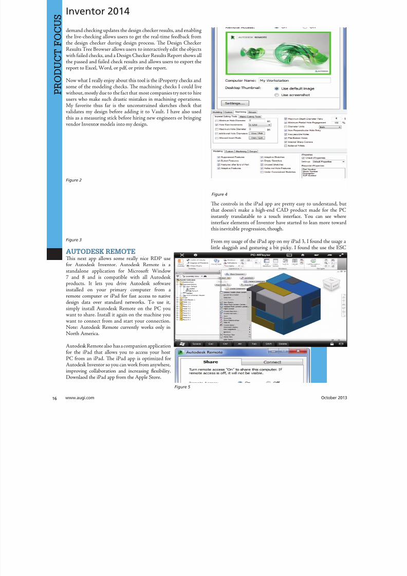
8122019 augi world 2013 10
httpslidepdfcomreaderfullaugi-world-2013-10 1652wwwaugicom October 20
Inventor 2014
PRO
DUCT
FOCUS
demand checking updates the design checker results and enablingthe live-checking allows users to get the real-time feedback fromthe design checker during design process Te Design CheckerResults ree Browser allows users to interactively edit the objectswith failed checks and a Design Checker Results Report shows allthe passed and failed check results and allows users to export thereport to Excel Word or pdf or print the report
Now what I really enjoy about this tool is the iProperty checks andsome of the modeling checks Te machining checks I could livewithout mostly due to the fact that most companies try not to hireusers who make such drastic mistakes in machining operationsMy favorite thus far is the unconstrained sketches check thatvalidates my design before adding it to Vault I have also usedthis as a measuring stick before hiring new engineers or bringingvendor Inventor models into my design
AUTODESK REMOTETis next app allows some really nice RDP usefor Autodesk Inventor Autodesk Remote is astandalone application for Microsoft Window7 and 8 and is compatible with all Autodeskproducts It lets you drive Autodesk softwareinstalled on your primary computer from aremote computer or iPad for fast access to nativedesign data over standard networks o use itsimply install Autodesk Remote on the PC you
want to share Install it again on the machine youwant to connect from and start your connectionNote Autodesk Remote currently works only inNorth America
Autodesk Remote also has a companion applicationfor the iPad that allows you to access your hostPC from an iPad Te iPad app is optimized forAutodesk Inventor so you can work from anywhereimproving collaboration and increasing flexibilityDownlaod the iPad app from the Apple Store
Te controls in the iPad app are pretty easy to understand bthat doesnrsquot make a high-end CAD product made for the Pinstantly translatable to a touch interface You can see wheinterface elements of Inventor have started to lean more towarthis inevitable progression though
From my usage of the iPad app on my iPad 3 I found the usagelittle sluggish and gesturing a bit picky I found the use the ES
Figure 2
Figure 3
Figure 4
Figure 5
8122019 augi world 2013 10
httpslidepdfcomreaderfullaugi-world-2013-10 1752October 2013 wwwaugiworldcom
Inventor 2014
key a mandatory function as I often initiated one navigation tooland found myself trying to start something else before finishing thetool I was in In the end I see some fantastic usage on the horizonfor this app but right now it is pretty gimmicky for my taste I dopicture myself at some point on my front porch with my tabletinstead of my computer I would look cooler to the neighborhoodkids too
Be aware you will probably have to troubleshoot the setup of thisapp a bit I had to lock and unlock my computer and restart theapp several times before I got it just right
FEATURE RECOGNITIONTe Feature Recognition application converts neutral 3D CAD
models such as SEP SA or IGES solids into full-featuredAutodesk Inventor models Feature mapping could be executedautomatically or interactively as needed to maintain design intentCurrently there is one Automatic Feature Recognition commandand eight feature recognition commands you can use
Automatic Feature Recognition attempts to recognize specificfeature types and populate the browser tree with the recognizedfeatures A dialog box displays the feature types you can recognizein the Features section with the defaults checked You can selectfeatures you want to recognize and deselect features you do notwant to recognize
When you import a file it will offer to start feature recognition Ifyou decide to do it later you will have to find your Base1 solid inyour tree and right click on it to start it again
Tis tool has been around for a long time previously only on
Autodesk Labs Personally I donrsquot like it mainly because I have toconstrain and dimension the sketches when they get recognized bythe tool If your goal is to bring in a solid and then do some minormodifications to it then you are better off using the Edit Solidtools also shown in the image above If you want Work Plane toolsalso remember to turn off the Import into Repair Environment aswell before opening the file
If you really had to go the distance and recognize features it isactually a lot quicker and generally creates a more intelligentmodeling history if you just redo it yourself in Inventor Terecognition tools only lend themselves to simple parts inmost cases
Figure 6
Figure 7
Figure 8
Figure 9
8122019 augi world 2013 10
httpslidepdfcomreaderfullaugi-world-2013-10 1852wwwaugicom October 20
Inventor 2014
PRO
DUCT
FOCUS
WORK FEATURE VISIBILITYTis product allows Inventor users to manage all work featurevisibility in a fast and easy way keeping full awareness of the involvedentities Tis app consists of six buttons on part environment andanother six on assembly environment Inside of part environmenta user can choose to enable or disable the visibility property ofplanes axes or points Inside of assembly environment a user can
also choose on which components to enable or disable the visibilityproperty of planes axes or points
I had a little trouble with this app in the assembly environmentbut that was due to some bad installation files Tis is one appreally worth the $099 How often have you been in an assemblyand not wanted to go back to the part files to turn on and offwork features I recommend ungrouping them so you access bothcommands faster
SHEET METAL FLAT EXPORTTere seems to be a plethora of these apps on the Exchange witheach of them varying in price and options In general the ideabehind these apps is to help automate the process of getting a DXF
to a machine that reads them for manufacturing in a more efficientmanner Tese programs will scan an assembly file and find thesheet metal files on which to perform their routines
Te different variations of this program range from free trialsupwards of $100 for the paid apps I started with one that gave me
a ldquoliterdquo version that would do 20 sheet metal files and I liked it much I started using the full version
FEATURE MIGRATORTe Feature Migrator tool allows Inventor users to more eascreate part features from assembly features User can migraassembly features either by selecting them in the Feature Migratbrowser or by right-clicking on one or several of them and theusing the ldquoSend to Partsrdquo commands Features can also be directmigrated from the regular Inventor model browser using thcontext menu item added by the add-in
Once the operation of migrating features is completed the FeatuMigrator displays a dialog that provides information about thresults Tis first dialog is a ldquohigh-levelrdquo report of the migrationprovides the opportunity for the user to select the action to takfor all the assembly features migrated Suppress if SucceedeSuppress always Delete if Succeeded Delete always or Nothingalso for the part features that havenrsquot been migrated correctSuppress Delete or Nothing Features created by the add-in cbe in an invalid state in the parts for a number of reasons
Te user can also see when a feature is out of date from thassembly and perform updates from the part side
Figure 10
Figure 11
Figure 12
8122019 augi world 2013 10
httpslidepdfcomreaderfullaugi-world-2013-10 1952
8122019 augi world 2013 10
httpslidepdfcomreaderfullaugi-world-2013-10 2052wwwaugicom October 20
Inventor 2014
PRO
DUCT
FOCUS
TIME STAMPime Stamp is an Autodesk Inventor add-in that provides bull A low-cost simple-to-use tool that adds plot time information
to your printsbull A plot stamp that does not dirty the Inventor drawing
documentbull
A simple dockable user interface that keeps out of the way
Te ime Stamp editor lets you size position and orient thestamp relative to the adjacent sheet edges You can include datetime and current user information in the stamp Te time stamponly appears on the plot it does not alter the Inventor drawing
What I really like about this app even though it costs $500 perlicense is that you can find the price yourself and buy it It doeseverything it says it does and it provides an easy-to-use interfacewith an icon that changes based on whether the tool is on or offIf you want even more control over your plot stamping there is amore professional version offered by this company on their websitefor about $4000 a license which will allow more reporting fieldsand more control on the look and location of the stamp
SIMPLE SHEET SETTINGSSimple Sheet Settings combines the existing sheet settings withsome new tools such as changing the title block and also the abilityto make changes to all sheets in a document at once
Instead of first deleting the existing title block from a sheetexpanding the title block folder and inserting the desired titleblock then opening another window to change the sheet size andorientation just click the ldquoSettingsrdquo button located on the Sheetspanel in the Placed Views tab (right next to ldquoNew Sheetrdquo) andhave access to all those options in one location
When the Simple Sheet Settings window is loaded it gathers all the existing title block names and puts them into one drop-dowmenu o change the title block on the current sheet simply selethe desired title block from the drop-down menu and click OKTere is also the ability to change the title block sheet size ansheet orientation to all sheets at one time
Tis is a great little app that saves clicks and only costs a dollaQuite useful and no real setup involved
INTERACTIVE TUTORIALTe Create an Interactive utorial app provides instructions fcreating your own interactive Inventor tutorial Te Guide alincludes how to customize the Welcome Screen to display yointeractive tutorial and add to the ribbon
Tis one definitely falls under the ldquotoo much time on your handuser or CAD admin After reading through the guide on how create the interactive tutorials you find yourself asking the questioldquoWhy donrsquot I just save videos of the process we use in a companserver locationrdquo And that is when you uninstall this app as yohave realized that while it sounded good to you at first there abetter ways to accomplish the goal of company-specific tutoria
and process documentation
Figure 16
Figure 17
8122019 augi world 2013 10
httpslidepdfcomreaderfullaugi-world-2013-10 2152October 2013 wwwaugiworldcom
Inventor 2014
Te tools actually rely on too much externally controlled softwaresuch as Camtasia and other plug-ins and third-party apps to makeit work correctly Save your time and just use Camtasia from
echsmith to do your bidding
KEEPING UP TO DATEWith all these apps it is easy to understand how a user could getbehind on the updates to so many tools With that in mind theExchange Manager found on the ools tab in Inventor will keeptrack of that for you and offer assistance not only in updating butalso uninstalling and specialized help for each app
As a reminder with regard to third-party apps if you startexperiencing undesired effects in Inventor start turning add-ins
off one by one until you isolate which one is giving you fits Properreporting back on the app to the developers makes everyonehappier when the issue gets resolved Tus far I havenrsquot had nearas many issues as I thought I would have
ANY MANY MOREWith 80+ apps currently in the store and about 60 of them ready
for 2014 at the time of this article you should take some time andlook through what is available Tere are apps which are very nicheto the user base as well as those that have you scratching your headover why they are not already part of the core software Below aresome I would write about if I had more room in the article andora fatter PayPal walletbull BOM oolsbull EDM Expressbull Sketch Symbol Librarybull SolidWorks iProperty Importbull Quick Viewsbull 3D Pipebull Point Linkerbull Kwikools
Mark Flayler is an application engi-neer with IMAGINi echnologiesspecializing in manufacturing environ-ments He has implemented Autodeskmanufacturing products within severalindustries including the blowinjectionmolding automotive and custom ma-chinery markets When not providingtraining support and implementationhe writes the IMAGINi Manufac-turing Blog and takes an active role inthe manufacturing community Markis an AC certified instructor and isPSE and AC certified in AutoCADAutoCAD Mechanical AutoCADElectrical Autodesk Data Manage-ment and Autodesk Inventor
Figure 18
Figure 19
8122019 augi world 2013 10
httpslidepdfcomreaderfullaugi-world-2013-10 2252wwwaugicom October 20
SPECIALFEATUREAUGI Forums by Melanie Perr
The AUGI Forums are as always a busyplace Ask a question and you mightsee half a dozen varied methods andworkarounds posted in a single thread If
you have not had any questions yourself I would stilllike to encourage you to pop into the Forums and see
if there are any problems you could solve especially if you use one
of the less adopted products Tere will always be many helpinghands in the AutoCAD and Revit Forums but what about themechanical products or design visualization or structural detailingForums Peek in and see if you can share your experiences andwisdom with the community
I confess that I only scoured the English-speaking Forums forcontent for this article but please keep in mind that there areAUGI Forums available in 12 other languages so users have theoption of asking for support in their native tongue
AUTOCAD ndash SYSTEM VARIABLE
DISCUSSIONhttpbitly15M1hB9
Tis topic started out when a user couldnrsquot delete Te solution wasultimately the PICKFIRS variable but the discussion evolved tosafeguarding other variables automatically just to protect against aloss of settings in the event of a crash User Coloradomrg offeredthe safeguard shown in figure 1
Norton_cad also suggestsDIMLFAC EXPER andBLIPMODE be addedto the list
REVIT ndash
UNDERLAY
BEHAVIOR
EXPLAINEDhttpbitly15M1iFd
Mschroeder opened thediscussion with If you haveever wondered why some wallsdonrsquot show up in underlays or
show up inconsistently from floor to floor or why roofs and vieranges affect their behavior then read on
First rule of underlays Underlay view extent properties (cut rangdepth) are not user modifiable and not coupled to any othviewrsquos properties
Itrsquos also been mentioned ldquoIf objects are visible in the view ranof your current view AND in the view range of your Underlathey are automatically hidden in your underlay so there isnrsquotdouble instancerdquo
Users twiceroadsfool and dbaldacchino helped clarify the effecby posting sample models and pertinent data from the AutodeKnowledgebase and Autodesk Support Visibility View RangDetail Level and Cut Planes are all touched on in this discussioNeed clarity on how to make the most of Underlays Check inthis thread on the Forums
LISP ndash MAKING A DIALOG BOX RETAIN
ITS SELECTIONShttpbitly15JzMCc
Te LISP Forum always has such fascinating topics it is hato decide which to highlight From locking OSNAP options setting Explode options along with troubleshooting of existincode But the discussion surrounding the tutorials and metho
to retain selectioin a dialog box wvaried and lively so had to check it ou r e a v e s 0 4 4 1 3 2 1
even posted a sampdcl file when he wfinished
String Theory
8122019 augi world 2013 10
httpslidepdfcomreaderfullaugi-world-2013-10 2352October 2013 wwwaugiworldcom
AUGI Forums
AUTOCAD ELECTRICAL ndash LINES BEING
LABELED AS WIREShttpbitly1ew9p9D
Dinochrome says that one of his coworkers has reported aproblem with regular AutoCAD lines being labeled as wires
Crosswire35 advises ry checking your wire type edit dialogbox and make sure the ldquomake all lines valid wiresrdquo checkbox is unchecked
And IMCO goes on to say Using the vanilla line command inACADE will still place that line on a wire layer Change your linesto layer 0 and ACADE will not give them a wire number
AUTOCAD STRUCTURAL DETAILING ndash
TUTORIALShttpbitly17kW7cc
Te consensus is that this product is a little confusing to figure outand that most of the tutorials out there are older Most productshave a few videos floating around on Youube but this one doesnot seem to have too many yet
Jpo82 chimes in with I guess only tutorials forthis software are those found at Autodesk websiteTey are for versions 2010 and 2011 but still validhttpusaautodeskcomadskservlet12ampid=13111928 Irsquom not sure but sometimes I feel that the only new feature inASD 2013 is that itrsquos more stable than previous releases
Lucis29 goes on to say Also you might check some movieshttpwwwrobotofficecomasd but they are very old
Spenner then linked to his reporting of the Service Pack andissues it addressed hoping that it addressed some of the issuesthat came up in this discussion
NAVISWORKS ndash IMPROVE ANIMATION
EXPORT QUALITYhttpbitly1fQLoIv
Different methods are discussed from exporting individual imageframes to exporting a video (and how long) but I will leave youwith the following list from Revit For Breakfast
Here are the secrets to movies in Navisworks1 Donrsquot use materials ndash you make your render time much longer2 Use the PNG export option 15fps3 Make your video export twice as long as you need Ten speed it
up for a faux 30fps Tis is faster4 Look up the Navisworks blog by Lee Mullin and Paul Walker
about gooch and phong Tere is your faux render setting5 If you have NW 2012 you wonrsquot have gooch or phong but you
will have better export options 2013 has gooch and Phong butfewer export options
6 Te flickering occurs when multiple shapes overlap If you care
delete them in your export model Sometimes flickering occurs
in the generation of your frames on the PNG export You mayhave a frame that is ldquooffrdquo
7 Set your anti-aliasing to 4x or better on the png export8 Check out my old post httpforumsaugicomshowthread
php132209-Animation-Resolutionampp=1138298ampviewfull=1post1138298
CAD MANAGEMENT ndash NETWORK DRIVE
CHANGED BY IT WITHOUT WARNINGhttpbitly18J4k9c
Blackbox advises edinsmore595165 straight off to utilize theReference Manager program that comes with AutoCAD inorder to reconnect all of the external reference paths that werebroken when the I department upgraded their archaic serversHe further points out that moving from hard pathing to relativepathing would make things easier in the future
Feargt offers another twist Another option which would workon a need only basis when you open the specific drawing Change
XREF and Image paths in drawing to Network path throughscript on a need only basis Basically this will only change pathsPlace this line in a acaddoclsp file(command ldquoscriptrdquo ldquoyourserver and pathXREFREDIRECscrrdquo)and the following in a script fileREDIRB enter name of path to be replacedP enter new path
Tere was also a debate in this thread about obstacles and benefitsof user-managed and I-managed drive mapping
Melanie Perry is a Facilites-Manage-ment Coordinator and echnical Edi-tor in St Louis MO She is the AUGISalary Survey Manager and is curring-ly serving as an Officer on the Board ofDirectors Melanie can be reached atmistressofthedorknessgmailcomor found on witter asMistresDorkness
OTHER HOT TOPICSHave you found a Forum solution so mind-bogglinglyuseful that you leapt out of your chair with a whoopingcheer (or were at least tempted to) Please let me know Asingle person cannot read every post in our bustling AUGIForums so if you would like to see a thread highlighted ina future edition of String Teory feel free to let me knowSend me Wanderer a PM in the Forums or send an emailto MelaniePerryaugicom
See you on the Forums
8122019 augi world 2013 10
httpslidepdfcomreaderfullaugi-world-2013-10 2452wwwaugicom October 20
Revit Architecture 2014
PRO
DUCT
FOCUS
by Martijn de Rie
Myth Buster
Revit amp IFCPart 3
Irsquove given a lot of thought as to how this trilogyof articles should end At first I thought Irsquoduse the Coordination View 20 EXPRESS-GWallPaper for IFC2x3 (httpwwwmdr-
adviesnlwp-contentuploadsCoordinationView_V2-0_WallPaper_IFC2X3_Version-1pdf ) as a stepping stoneto give an ldquoIFC for Dummiesrdquo type of solution But that turnedout to be quite lengthy and rather boring But the link is includedabove for obvious reasonsmdashitrsquos useful
So I went back a little and asked myself ldquoWhy IFCrdquo And with thatquestion the inevitable follow-up immediately appeared ldquoWhynot IFCrdquo I realized that in the previous articles I failed to explainwhy in my humble opinion we should care about this somewhatcrooked badly implemented severe headache-inducing formatTerefore instead of explaining the fundamental technicalities ofIFC that can be explored in other places this final installment willexplore the Why versus Why Not IFC discussion and begin withthe latter
WHY NOT IFCWhen everybody uses Autodeskreg RevitregWell in this case itrsquos a no-brainer Share your Revit files Period
Loss of dataTis is an easier way to share data instead of hacking your wthrough IFC and praying your stuff doesnrsquot get lost in the proce
Even when you manage to export your geometry through IFtherersquos always loss of data
Loss of intelligence during importEven if you only need to send over geometry not data importithat into Revit makes it utterly useless All constraints are locomponent parametrics are gone and so on
Availability of bidirectional linksWhen not everyone uses Revit on a given project (which is quoften when yoursquore not located in the US) why not simply ua bidirectional linking between proprietary software standardTis can be easier and better to control
8122019 augi world 2013 10
httpslidepdfcomreaderfullaugi-world-2013-10 2552October 2013 wwwaugiworldcom
Revit Architecture 2014
WHY IFCWhich may be asked as why would you want to use IFC Or moreaccurately why would you want that option available
Consider what Sir Arthur Conan Doyle wrote ldquoOnce you eliminatethe impossible whatever remains no matter how improbablemust be the truthrdquo
Letrsquos put that to the test shall we
When everybody uses RevitOkay simple math Autodesk has around 7000 employees Teworld has about 72 billion people What are the chances someonenot working for Autodesk has a brilliant idea and creates thesoftware you need tomorrow Tere will always be better solutionsTey might not be viable for you overall but therersquos no reason toshut down access to them Revit is a wonderful generic tool forwhich I see a brilliant future with all kinds of additions for specificniche-markets like AutoCAD has
What about today DDS is MEP-engineering software that cando energy calculations (not simulations) inside your modelRhino lets you model things on the fly that could (arguably)take ages in Revitmdashif you ever get them done ekla lays wasteto the Revit structural rebar functionality any day of the weekwithout breaking a sweat Solibri is a wonderful solution for clashdetection and most importantly rule-based model checking andreportingmdashsomething Revit (or Navisworks) doesnrsquot do
Should I go on
Only problem for all this magnificent software Itrsquos either based onthe IFC format or requires model exchange through IFC
Te fact of the matter is there will always be better softwareAny one may be the software for you but that doesnrsquot mean yourpartners associates etc need to have the choice to use it forcedupon them
Loss of dataOn July 1 2013 there was an extra release for Autodesk softwareTe Sourceforge Open Source IFC Exporter released a new versionthat incorporated the option to map custom Revit parameters(shared or non-shared family or project even calculated values) totheir IFC counterparts
On September 28 2013 I had the honor of showing the secondstep in a complete and controllable data export from Revit
During my RC Europe class I showed the new option to create acustom IFC Property Set and map any given Revit parameter intoIFC fully customizable
IFC does not automatically lead to loss of data Tat idea is simplynot true Incomplete implementation in Revit does lead to loss ofdata As of now you are able to put any piece of data into an IFCeven calculated values And we didnrsquot change the IFC format We
just improved implementation in Revit
Loss of intelligence during importldquoJust because something hasnrsquot happened yet doesnrsquot meanitrsquos impossiblerdquo
I donrsquot know who originally had this insight and I doubt it to bethe movie line I remember but it is true
In the same RC Europe class I showed a native Revit familybeing exported to IFC altered and re-importedmdashwhile keepingall parametric constraints and even adjusting to the alterationsmade directly in the IFC file It is possible but not with thecurrent importer
Availability of bidirectional linksIrsquove been using Revit for almost 10 years now For 4-5 years I didnrsquotknow about IFC at all Before a year ago this was my strongestargument against IFC Why would you need a generic ldquolanguagerdquowith all its limitations (of which there are) weaker implementationand use of parametric capabilities (because it has) and lag-times indevelopment (by nature)
IFC will never be able to do what native software does simplybecause itrsquos responsive in nature Development budgets are afraction of what Autodesk rimble or Nemetschek get to spendon their software
So why not keep it simple and use a bidirectional link Revit has itwith a lot of other Autodesk software and third-party applications
But how long have we waited for them And are they even trulybidirectional Do they exactly do what you want them to do In myhumble opinion the answer to these questions is not very inspiringEven bidirectional links tend to have major limitations and severe
constraints in flexibility And most important Te link itself isalso propriety software No way of adjusting it to your needs
WHAT IF MORE PEOPLE STOPPED
TALKING ABOUT IT AND JUST GOT
INVOLVEDTe improbableFirst off itrsquos a matter of simple logic As Sir Arthur suggested ifwe can successfully check off all likely options to NO want touse IFC doesnrsquot that mean the improbable is true Tat IFC is infact a valuable tool in our toolkit and we should be able to use it
when necessary
Mind you Irsquom not saying you should use IFC If yoursquore on a Revit-only project it would be insane Just send and receive RVs Tefact is this will only be viable for limited parts of the buildinglifecycle If yoursquore lucky the entire design team is on Revit Butmanufacturers have other software facility managers too
As for the design team what if the best structural engineer is not[on Revit] or the MEP guy that has loads of experience in similarprojects Would you settle for second-best just because someoneuses the same brand of tools you do I wouldnrsquot
8122019 augi world 2013 10
httpslidepdfcomreaderfullaugi-world-2013-10 2652wwwaugicom October 20
PRO
DUCT
FOCUS
Revit Architecture 2013
Open AccessWhich brings us to the biggest advantage of IFC (or any open
format) itrsquos open Which means itrsquos adjustable to your needs Nowdonrsquot go ldquothatrsquos too difficult expensiverdquo Tatrsquos bullocks
Te first external enhancement to the Open Source Exporter wascreated by om Pesman a self-employed API specialist
Parametric IFCImplemented by Jon Mirtschin also self-employed IFCparametrics is available Agreed Jon is a well-known IFC guru butstill the point holds
Custom property sets and parametersWim as owner of a small MEP engineering firm hasadded functionalities toward this end and hersquos not even a trueAPI specialist
All these developments were done for free by altruistic volunteerefforts as part of the creation of the Dutch Revit Standards Andof course with the invaluable help of the Autodesk Open SourceIFC Exporter team Angel Velez in particular
But what if these guys actually got paid What if this projectwasnrsquot a Saturday night side-job What if more people stoppedtalking about it and just got involvedmdasheither by themselves or byleveraging experts to get what is needed Te entire IFC format is
Open Source the source code is out there which basically meansyou can do whatever you want and create whatever you needmdasheven on a project-by-project basis
BIM ITrsquoS THE ldquoIrdquo THAT MATTERSIn my humble opinion the entire debate on BIM is focusing on thewrong part of the acronym I donrsquot care if ldquoBuildingrdquo is a noun ora verb Nor do I care whether itrsquos ldquoModelrdquo or ldquoModelingrdquo nor am Icommenting on whether one should say ldquoBIM Modelrdquo
Itrsquos the ldquoIrdquo that matters If wersquore collaborating the Informationis most all I care about I just want your datamdashin the leanest
smartest and most effective way possible
A Revit model will do conversely a lot of times A Revit model w
give me heaps of data I donrsquot want geometry I donrsquot care about ana file format I canrsquot use Now we can all keep on being really anabout it or we can simply use the tools available to us one of thebeing IFC
A FINAL NOTEAs stated at the beginning of the article I really enjoyed writinthis series and for now this is the last of the series But if yoursquointerested in more tips and tricks on IFC let me know I might able to persuade the guys at AUGI to let me write about it againLord knows there is still a lot to talk about regarding IFC
Martijn de Riet is a self-employedBIM Consultant from the Nether-lands working with Revit since version51 Martijn has a bachelor degree inBuilding Science After his studieshe started his own engineering firmworking for contractors architects and
private clients Starting in 2007 hiscompany transformed into a full-timeBIM consultancy service At the mo-ment Martijnrsquos clients vary from mid-sized architectural firms to the largest
dutch General Contracter and MEPEngineering firms with a focus onspecific corporate solutions design andimplementations of Revit and BIMworkflows Martijn is a member ofthe Dutch Revit User Group and cur-rently working on creating a Masteremplate and Component LibraryHe provides lectures for companiestechnical universities seminars etc ona regular basis
Itrsquos the ldquoIrdquo that matters If wersquore collaborating the Information is most all I care about I justwant your datamdashin the leanest smartest and
most effective way possible
8122019 augi world 2013 10
httpslidepdfcomreaderfullaugi-world-2013-10 2752
wwwxicomputercom
8122019 augi world 2013 10
httpslidepdfcomreaderfullaugi-world-2013-10 2852wwwaugicom October 20
3ds Max 2014
PRO
DUCT
FOCUS
by Chris Murra
SUMMARY WHATrsquoS
CUSTOMIZABLE IN MAX
(HIGH LEVEL)When it comes to the customizability of Autodesk 3ds Maxregitrsquos no secret that it can morph itself into whatever you want theprogram to become
Whether yoursquore a modeler animator lighter rigger generalist ortechnical artist 3ds Max can become your own personalized toolbox that is an extension of your own hand in your daily workYou can now combine different command types (such as creatingobjects and object modifiers) into a single menu reducing themouse travel and improving efficiency
In this article wersquore going to take a closer look at one specificaspect of customization with 3ds Max the new enhanced UI Aspart of this article besides taking a deep dive into the operationof this feature I will also be showing how I created the ldquoMographrdquo
tools UI that includes custom buttons and icons At the end this article I will also provide a link to this UI so you can use customize it yourself or share it with others
ENHANCED UI SUMMARYWhat is the Enhanced UI
Te Enhanced UI is a new graphical user interface system thdoes two main things
1) It provides a refreshed 3ds Max user interface with updattool categories and new clusters of pre-existing tools in groupinthat are more akin to their intended purpose as opposed to somtechnical requirement for menu placement
2) It provides a way to allow you the end user to customize thmenu system in almost any way you choose Te drop-down menare ldquotear-ablerdquo (not to be confused with ldquoterriblerdquohellip but I digresand the resulting configurations are savable either by scene or
3ds MaxEssentialsCustomizing
the UI
8122019 augi world 2013 10
httpslidepdfcomreaderfullaugi-world-2013-10 2952October 2013 wwwaugiworldcom
3ds Max 2014
a preset Tey are also distributable and deployable so they can beshared with others
Where is the Enhanced UITe Enhanced UI can be found in the upper left hand corner of themain UI at the very top of the screen Tere is a drop-down menuthat says ldquoWorkspace Defaultrdquo Tis default is the same baselineUI that ships with all 3ds Max installs (Figure 1)
Within the drop-down you can find the ldquoDefault with EnhancedMenusrdquo Tis is the alternative default menu system that youcan use on its own or use as a starting point to create your owncustomized menus
BASIC DEFAULT CUSTOMIZATIONEnhanced UI Customization BasicsNow that wersquove enabled the Enhanced UI how can we change it
SOP Before you begin mucking around with the UI Itrsquos importantto understand what I call the ldquosave-logicrdquo as it pertains to custom UIs
Te UI Save LogicIf you plan on saving this UI for future use there is a specificmethod you must follow to properly save the UI you want and notwreck the default Enhanced UI
Te Save Logic is as follows Itrsquos simple but important
Step 1 urn on Enhanced Default UI (Figure 3)
Step 2 Click ldquoSave as New Workspacerdquo FIRS At this point youwill be prompted for a new name (Figure 4)
Step 3 Edit and change the UI at will
NOE All future edits are ldquoautomatically rememberedrdquo as you go (Iintentionally did not use the word ldquosaverdquo)
Step 4 Te ldquosave as default staterdquo button is important When wehave completed the customization process we then choose thisbutton to ldquolockrdquo in the changes Tis is different than Saving a UIwith a custom name
HO IP ldquoBut this methodology seems backwardrdquo
I can see how yoursquod say that but remember that any changes you make
to any enhanced UI are automatically ldquorememberedrdquo If you create acustom UI then while working you make some temporary changeswhen doing something specific those little changes are automaticallyremembered If you want to return to the default state [of yourcustomized UI] you select ldquoReset to default staterdquo Tis does NObring back the default Max UI rather it brings back the customizedUI you created in ldquolockedrdquo in Step 4
Okay now that you have the save logic down letrsquos begin customizing
1) If you havenrsquot done so already turn on the Default Enhanced UI
2) Go to ldquoManage workspacesrdquo from the drop-down and in the
Figure 1 Workspaces are in the Workspace drop-down menu
Figure 2 Default UI (left) and the Default Enhanced UI (right)
Figure 4 Saving the New UI Workspace
Figure 3 Turning on the Enhanced Default UI
8122019 augi world 2013 10
httpslidepdfcomreaderfullaugi-world-2013-10 3052wwwaugicom October 20
3ds Max 2014
PRO
DUCT
FOCUS
Manage workspaces dialog choose ldquoSave as new Workspacerdquo Giveit a specific name
3) Begin making your desired changes
Since a custom UI is specific to any one individual letrsquos take a lookat what types of customizations can be made
Simple ChangesOne of the simplest things to do is peel off any commandgroup (see Figure 5) Just click the group title bar and drag Tecommand group becomes a floating dialog box Now just becauseyoursquove peeled it off does not mean that yoursquove removed it fromthe drop-down menu Te ldquooriginalrdquo command group remains inthe drop-down You can just close the floating dialog when yoursquoredone with it
Probably the simplest thing you can do is reorganize the menusIn each drop-down menu appears a group of commands You maynotice that some command groups are icons and some are words(Figure 6) o change the appearance of the commands there is asmall icon in the upper right corner of each group of commands(Figure 7)
Te next change is alreally simple Is tcommand group op(expanded) or clos(rolled up) Just clion the plus or minsign in the upper le
corner to set this stafor the next time yolaunch 3ds Max (Figu8) Remember thesettings are saved as yogo so whether it is opor closed is your choicbut the state the menis in when you cloMax is the one that remembered the netime Max opens
What about Saving tDefault state More othis later
Once you have floating menu yocan combine differecommand groups dragging any othcommand group to aother floating dial
that yoursquove created Tis makes for easy creation of custom dialo
based on specific tasks Figure 9 shows a command group fcharacter animationFigure 5 A floating menu that has been torn off the drop-downmenu
Figure 6 The different display states of the menus
Figure 7 Changing menu layouts
Figure 8 Rollouts
8122019 augi world 2013 10
httpslidepdfcomreaderfullaugi-world-2013-10 3152October 2013 wwwaugiworldcom
3ds Max 2014
ADVANCED CUSTOMIZATION
What about completely custom interfaces Herersquos how we do thatwith the Enhanced UI menu system
Te following is the high-level overview of the process Wersquoll thenunpack each step in more detail
If you havenrsquot read the section on Basic default customizationplease do so before continuing Before starting this phase ofcreating your new UI you should have saved your new UI stateTat process is explained in the previous section
1) Create a main drop-down menu (like ldquoMy oolsrdquo)
2) Create a tools category menu into which you will place yourtools (a submenu such as ldquoModeling oolsrdquo or ldquoAnimation oolsrdquo)Drop-downs can have more than one subcategory
3) Add commands to various submenus
4) Clean up the UI by creating custom names adding separatorsor creating custom icons
First letrsquos create a new menu for the menu bar Tis is done easilyfrom the CustomizegtCustomize [Rollout]gtCustomize UserInterface dialog box
Steps for Creating a Drop-Down Menu1) Create a New Menu and give it a name (see Figure 10)
2) Locate your new menu in the Menus window It will be listedalphabetically (Figure 11)
Figure 9 Multiple command groups in one menu
Figure 10 ndash Creating a new drop down menu
Figure 11 Location of new menu
8122019 augi world 2013 10
httpslidepdfcomreaderfullaugi-world-2013-10 3252wwwaugicom October 20
3ds Max 2014
PRO
DUCT
FOCUS
3) Drag your newly created menu category over to the column onthe right Tis will add your new drop-down menu to the interfaceimmediately and you can begin populating it with menu items (seeFigure 12)
UI DESIGN IP Te actual menu name and display name can bedifferent I used a custom menu name behind the scenes so I couldeasily differentiate my menus from the ones created by default or other
tool companies After you create a menu and add it to the right column you can right-click on it and change its display name (see Figure 13)
Next letrsquos create a command group1) Just like in Step 1 from the previous section create a new men
2) Tis time before you drag it to the right column click thplus sign next to your drop-down menu item to expand it Tedrag the new item to the right column dropping it ldquounderrdquo thmenu name
3) Drag any commands from the Commands window on the leto the submenu on the right (see Figure 15)
Herersquos an example from my Mograph ools workspace thshows how a completed menu looks once it is created (Figu16) In the following figure you see both the menu as it appeain the Customize UI dialog and the actual menu (which has bepeeled off)
Notice that some of the commands on the menu are greyed ouTatrsquos because this new menu combines both ldquoObject creatcommands and ldquoObject Modify Commandsrdquo in one menTey will remain grey until you create an object on which thwill be used
Figure 12 Adding the new menu to the UI
Figure 14 Creating a command group
Figure 15 Dragging commands onto the menu
Figure 13 Custom menu names
8122019 augi world 2013 10
httpslidepdfcomreaderfullaugi-world-2013-10 3352October 2013 wwwaugiworldcom
3ds Max 2014
Adding SeparatorsSeparating commands is easy and is recommended to help you oryour intended user make sense of the how the tools are arranged inthe menu Creating a separator is as easy as dragging one over theright column just like a menu or command
HO IP ldquoWhy do I need to create another menu Why canrsquot I addtools right to my menurdquo
Te main reason is that adding a submenu gives you the ability to tearoff the submenu If it werenrsquot in a submenu it wouldnrsquot be tear-ableSo itrsquos really a ldquobest practicesrdquo kind of thing But even if you try to notadd the submenu it will happen automatically Itrsquos important to do it
explicitly so you are aware of what submenus are in the menu and that you are the one in control of what command is going where
CUSTOM ICONSNo custom UI is complete without a custom set of iconsAdditionally not all commands in 3ds Max have their own iconyet But itrsquos important to realize that regardless of how you set up
your UI yoursquore still working within the framework of an existingapplication and there are boundaries to what you can edit andcreate Icons have specific requirements both in their creation(size) location and file name that must be adhered to in order forthem to work properly
SizeformatTe size of icon is pretty simple It must be 32x32 pixels andPNG format
LocationTe location is very specific New icons must be added to thislocation
CProgram FilesAutodesk3ds Max 2014UI_lnResourcesDarkIconsMain
Te new icons I created for the Mograph UI are shown inFigure 17)
Icon File NameIf yoursquore still with me at this point we are now getting into thenether regions of customizing a UI Tis is where things get a littletricky but itrsquos really not too bad File names are specific and aregenerated by the application (3ds Max)
So letrsquos begin First identify the command for which you want aniconmdashusually itrsquos one that doesnrsquot already have an icon But if itdoes and yoursquore changing it MAKE A BACK UP of the originalicon PNG file Tis is because as previously stated you donrsquot havecontrol over the file name Tat means if yoursquore creating your ownicon you need to overwrite the existing one and use its name foryour new icon So back up any original icons
Figure 16 The completed menu
Figure 17 ndash The created icons
8122019 augi world 2013 10
httpslidepdfcomreaderfullaugi-world-2013-10 3452wwwaugicom October 20
3ds Max 2014
PRO
DUCT
FOCUS
It really doesnrsquot matter whether you make the icon first or not ofind the name you need to use you need to navigate as follows
NOE Yoursquore about to edit the ribbon Tere is no need to save thesechanges as we are merely extracting information from it But if yoursquoredoing a lot of custom icon work you may want to save this change to theribbon so you can come back and continue your work in later sessionswithout have to recreate this every time just to get the proper file nameSaving this ribbon is not related to saving your default state of yourUI When yoursquore done creating all your UI icons you can just delete
whatever changes you make to the ribbon
1) Open the ldquoCustomize Ribbonrdquo dialog box
2) Create a new ldquotabrdquo by dragging it onto the ldquoExisting Ucolumn in the middle (see Figure 18)
3) Using the same drag method add a new ldquopanelrdquo to ttemp tab (Figure 19)
4) Now you can get the information you need Find tcommand for which you are creating an icon and dragto the panel
5) Locate the ldquoinfordquo portion of the ldquoPreview Windocolumn At the bottom of the column is the file namneeded to have the icon used properly by the applicati(Figure 20)
CONCLUSIONSo now you know how to create a custom UI scheme f3ds Max 2014 and up By using the Enhanced UI me
system itrsquos really easy to generate a multitude of workspathat allow Max to work the way you want to work
Te example used in this article was the ldquoMographrdquo UI thI created for NAB 2013 If you would like to downloand install it you can get it from my ldquoPinning the Stacblog on the Area herehttpareaautodeskcomblogschrismurray
Enjoy
Chris Murray works for Autodesk
Media amp Entertainment He istrained as an animator (3D variety)but considers himself a creative tech-nologist His daily role is a technicalldquoevangelistrdquo for Autodesk creating marketing deliverables for 3ds Max Heis the author of Mastering 3D StudioMax He has a Masters in Fine Arts(MFA) in Computer Animation fromMiami International University of Artand Design Follow him on witterchrismmurray
Figure 18 Creating a tab on the ribbon
Figure 19 Adding a panel to the tab
Figure 20 Finding the required file name
8122019 augi world 2013 10
httpslidepdfcomreaderfullaugi-world-2013-10 3552
AUGIMembersReach Higherwith ExpandedBenefitsAUGI is introducing three new Membership levelsthat will bring you more benefits than ever beforeEach level will bring you more content and expertiseto share with fellow members plus provide anexpanded more interactive website publicationaccess and much more
MEMBERMEMBER MEMBER
Basic members haveaccess tobull Forums
bullHotNews (last 12 months)
bull AUGIWorld (last 12 months)
DUES Free
Premier members haveaccess tobull Forums
bullHotNews (last 24 months)
bull AUGIWorld (last 24 months)
DUES $25
Professional members haveaccess tobull Forums
bullHotNews (full access)
bull AUGIWorld (full access and in print)
bull ADN 2013 Standard Membership Offer
DUES $100
Are you ready to upgrade yourself and your membership
Access additional benefits and upgrade at wwwaugicom
8122019 augi world 2013 10
httpslidepdfcomreaderfullaugi-world-2013-10 3652wwwaugicom October 20
AutoCAD MEP 2013
PRO
DUCT
FOCUS
by Vladimir Triantafillid
BIM IsWhatrsquos
Driving theIndustry
For the past decade many would arguethat building information modeling(BIM) has metastasized aggressivelythroughout the AEC industry but what
does BIM really mean More importantly whatdoes it do for us and for our industry Ask someone who hasbeen in this industry for more than 25 years or those nearingretirement and yoursquoll find that less than half see its value muchless care to make the effort with its implementation hesequestions mean something different for those who have beenin the industry the past 10-15 years Recent college graduates
however with their tech-savvy capacity and high expectationare eager to implement anything that resembles cutting-edgflashy technology ypical ly they are the ones most receptivenot adamant about putting their talents to use through BIM
I recently gave a BIM presentation with an emphasis on mchanical systems to the summer interns and new hires our companymdashall were non-BIM users except for onemdashbmy presentation did little justice to BIM Half of my audence had found a cure for their insomnia when they realizthis wasnrsquot the latest edition of ldquoCall of Dutyrdquo hat was n
8122019 augi world 2013 10
httpslidepdfcomreaderfullaugi-world-2013-10 3752October 2013 wwwaugiworldcom
AutoCAD MEP 2013
reflection on BIM by any measure Simply put I fell shortof connecting with a potentially captive audience eager toknow what really makes BIM intriguing or how it wouldgive them an edge in the industry I didnrsquot think to look pastpresenting the facts of its processes and benefits o simplyhave stated that proficiency in any of its many facets willpromote a lucrative career would give those still awake theimpetus to jump ship In hindsight the first step I shouldhave taken to begin this presentation was to ask what theywanted to get out of BIM
If you think itrsquos hard conveying the value and splendor ofBIM to receptive and impressionable young minds try toconvince the weathered veterans dead-set in their ldquooldtricksrdquo For every experienced veteran who has converted toBIM there are two ldquoold dogsrdquo that canrsquot shake ldquothe good olrsquodays when we used vellum and light tablesrdquo Guess whatmdashanincreasing amount of naysayers are starting to come aroundincluding those who say theyrsquove been burned by BIM in thepast hey are seeing the simple solutions BIM presents and
how these solutions translate into cost savings More andmore of those who had formerly questioned BIMrsquos utility areconvinced when installation efficiencies are not only real-ized but quantified
Another factor in the evolution of BIM is its tendency toexpand faster than the pace of its general population of us-ers hose of us proud to be catching up to what we think iscutting edge quickly realize it was just another false sense ofaccomplishment as BIMrsquos web continues to grow exponen-tially he solution is rather simple Focus on what you canhandle and always have the presence of mind and sense ofcaution to avoid being overwhelmed by the wake of BIMrsquos
progress herersquos plenty of money to be made and countlessfacets to explore as long we have the following mentality Welive in the information age and those wi lling to share knowl-edge will reap the rewards of communal synergy
On the opposite end of the spectrum you might find ourindustryrsquos opportunists In a hurried frenzy to claim theirspot in the intellectual property queue these opportunistsget carried away with pioneering what they assume is the lat-est improvements to BIM Instead of stopping to absorb anddevelop the benefits of 4D 5D 6D and so on the pioneersare spreading these ldquoDsrdquo thin with abandon further expand-
ing the gap between quality and quantity None of this i s tosay that wersquore heading in the wrong direction On the con-trary letrsquos call it more of a positive economic problemmdashthedemand for BIM expertise and development outweighs thesupply of available users
Fortunately as collegiate curricula catch on to this industrytrend the point of equilibrium will soon follow For as longas I can remember respective companiesrsquo 2D CAD depart-ments have been a significant source as the breeding groundfor potential BIM users While this route hasnrsquot changedregarding the career path of a draftsperson the source poolhas expanded to include architects engineers and construc-
tion managers just to name a few Itrsquos even hard not to noticeits stark demand when BIM and Revit courses are being in-creasingly offered at local community colleges I knew thenthat you didnrsquot necessarily need an undergraduate degreeback when I got my foot in the door of this industry hisprobably wonrsquot hold true in the coming years Still the privi-leged few who are already a part of this industry subset canrely on their experience in this fast-paced market to con-tinue to propel their careers forward ever faster All thesefew need to do is grab onto a small piece of BIMrsquos wing andhang on tight for the ride he fresh-out-of-college e ntrantsmight have a harder time grabbing onto this wing thatrsquos al-ready in motion
o those who are only vaguely famili ar with BIM it is typi-cally perceived as the equivalent of a 3D role-playing videogame In this case itrsquos not difficult to capture a ldquosnapshotrdquoimage of a 3D model shadows cast across random metal ob-
jects taking up space in an orderly fashion between ceil ingspaces and walls What is difficult is conveying the abun-dance of value behind the pretty picture to a client whorsquosonly interested in the pretty picture Who isnrsquot familiar withthe adage ldquoa picture is worth a thousand wordsrdquo Why notchange that saying to ldquoa BIM model is worth five thousandhyperlinksrdquo Now wersquore talking lifec ycles and facilities man-
More and moreof those who had
formerly questioned
BIMrsquos utilityare convinced
when installationefficiencies are notonly realized but
quantified
8122019 augi world 2013 10
httpslidepdfcomreaderfullaugi-world-2013-10 3852wwwaugicom October 20
AutoCAD MEP 2013
PRO
DUCT
FOCUS
agement his supposed video game has suddenly becomean encyclopedia of usable information But wait itrsquos not juststatic information thatrsquos stuck on a DVD on a shelf i n someownerrsquos random storage closet It has now become a livingdynamic source of real-time data Maintenance technicianswill know exactly where to go when the active 3D modelloaded on their laptop highlights a hot water pump needingservice while concurrently bringing up the cut sheets andoperation and maintenance manuals specific to that pumpor system Better still the source of information has shiftedfrom multiple stacks of large drawing sets collecting dust toseveral hundred gigabytes on a hard drive Yes Mrs Clientyour 3D BIM model will be usable for the next 20+ years
Even though you might not necessarily think about i t someof you probably realize that BIM has become the ldquomiddle-manrdquo for so many key components in the construction cyclewell beyond its intermediary role between design and con-struction phases You want to do some significant tenantimprovement in an existing building Laser-scan the exist-ing conditions hatrsquos BIM Is the general contractor rackingtheir brain trying to f igure out where to station the crane forthe project or pave the pathways for delivery trucks Nowtheyrsquore looking to BIM to answer these questions and opti-mize their decisions o take it a step further at which endof the building do we want to load thousands and thousands
of pounds of sheet metal and pipe And then which tradesshould be installing their systems first in any given area ofthe building hatrsquos right wersquore deriving sequencing andtimelines from the BIM model to e stablish the best routes totake while addressing any constructability issues BIM hasbecome the consultant that wears most of the hats Itrsquos ourone-stop shop
I know that Irsquove personified BIM as if itrsquos the brains behindall of its success Letrsquos take a moment to focus instead on itscollaborators or the sum of its integral parts to show thatin reality we are Dr Frankenstein and BIM is our monster
Except in our ca se wersquore beginning to ta me our monster anthose who were previously frightened by it are starting to sthat it indeed is no monster In fact while evolving to domdashand becomemdashgreater things BIM is transforming into aindustry hero he point of convergence is approaching bcause wersquore saving money time and even trees Soon enougBIM will be the industry standard even on the smaller proects Letrsquos keep the pedal to the meta l
You want to know the best news Most of us havenrsquot evebegun to scratch the surface of BIM but wersquore in strategpositions to reap the rewards aking the possibility of ivast potential into account isnrsquot it reassuring knowing th
in these tough economic times wersquore engaged in an industthat has a shortage of well-qualified BIM experts Our eposure alone sets us up for success Now ask yourselves thquestion Is BIM driving our industry or is it the BIM use
Vladimir riantafillidis works for aleading mechanical contractor in theSan Francisco Bay Area with morethan 10 years of experience in the in-dustry Although he has a bachelorrsquosdegree in biology his unique careerchoices have firmly rooted him in a
substantial BIM role awarding himthe opportunity of progressing along-side the relentless evolution of BIMOutside of his career hersquos always opento new adventures whether trying anew cuisine exotic travels or extremesports Te latter adventures have re-cently subsided as the balance of lifehas shifted his focus on spending timewith his growing family
You want to know the best news Most of us havenrsquot
even begun to scratch the surface of BIM but wersquore
in strategic positions to reap the rewards
8122019 augi world 2013 10
httpslidepdfcomreaderfullaugi-world-2013-10 3952
8122019 augi world 2013 10
httpslidepdfcomreaderfullaugi-world-2013-10 4052wwwaugicom October 20
Revit Structure 2014
PRO
DUCT
FOCUS
Streamlining
Sheet Listswith a Custom
Application
In this article we take a brief look a simpleadd-in for Autodeskreg Revitreg named X-Sheetswhich provides tools for incorporating sheetsfrom an AutoCADreg sheet set in a Revit sheet
list ypically this is handled by manually addingplaceholder sheets to the Revit sheet list Tis can be problematicbecause the sheet list becomes disconnected from the sourceand must be updated manually With X-Sheets sheet set datais exported directly from AutoCAD linked to a Revit project
and included in the sheet list by automatically addingupdatinplaceholder sheets For this example all structural scheduleplans elevations and section sheets are in Revit Structure Adetail sheets will be pulled from an external AutoCAD sheet set
X-SHEETS RIBBON PANEL Te first command on our ribbon panel is Discipline Tcommand is used to establish the Revit project parameter twhich the AutoCAD sheet subsets will be mapped For th
by Jonathan Albe
Figure 1 Revit X-Sheets ribbon panel
8122019 augi world 2013 10
httpslidepdfcomreaderfullaugi-world-2013-10 4152October 2013 wwwaugiworldcom
Revit Structure 2014
example we have created a project parameter named My DisciplineParameter Each Revit Structural sheet has been assigned a valueof SRUCURALmdashthe same as the subset name for theAutoCAD detail sheets Te sheet list is grouped and sorted bythis parameter
Te next command on the ribbon panel is Links Tis command isused to establish a link between the Revit project and XML file(s)
containing sheet information exported from AutoCAD You cancreate as many links as needed and use relative paths if required
Te next two commands Sheets and Update do the work ofaddingupdating placeholder sheets to the sheet list While theSheets command allows you to select individual sheets from linksto include in the sheet list the Update command includes all sheetsfrom all links
EXPORT SHEETS FROM AUTOCADFigure 3 shows the AutoCAD X-Sheets ribbon panel and asample sheet set containing structural detail sheets Notice thedetail sheets are grouped under a subset named SRUCURALTis subset name can be exported with each sheet and mapped to
the My Discipline Parameter in Revit Figure 3 shows the ExportSheets dialog with an option to include subset information and theability to exclude individual sheets Selecting the Export buttonprompts us with a dialog to save an XML file to be linked into ourRevit project
Figure 2 Discipline command dialog
Figure 3 AutoCAD X-Sheets ribbon panel and sample sheet set
Figure 4 Export sheets dialog
Figure 5 Export complete
8122019 augi world 2013 10
httpslidepdfcomreaderfullaugi-world-2013-10 4252wwwaugicom October 20
Revit Structure 2014
PRO
DUCT
FOCUS
ESTABLISH LINK TO XML FILE IN REVIT
PROJECTFigure 6 shows the Manage Links dialog A link has been added tothe XML file we generated when exporting sheets from AutoCADNotice there is an option to make the link path relative to our
Revit Project location
IMPORT SHEETS FROM XML LINKFigure 7 shows the Revit Structure sheet list before any sheetshave been imported from AutoCAD After selecting the Sheetscommand we are prompted with a Manage Sheets dialog
For this example we have selected all sheets from the XML linto include in our sheet list After confirming the dialog neplaceholder sheets are immediately added to the sheet list angrouped according to the SubsetDiscipline mapping Te neplaceholder sheets are identified behind the scenes as being relatto the X-Sheets XML link for later updating
Figure 6 Manage Links dialog
Figure 9 Sheet list after import
Figure 7 Sheet list before import
Figure 8 Manage Sheets dialog
The X-Sheets
add-in is a great tool
for incorporating
AutoCAD sheets into
a Revit sheet list
8122019 augi world 2013 10
httpslidepdfcomreaderfullaugi-world-2013-10 4352October 2013 wwwaugiworldcom
Revit Structure 2014
UPDATE SHEETSFigure 10 shows the Export Sheets dialog in AutoCAD afterdetail sheets have been renumbered to include ldquo-Ardquo When changesare made to AutoCAD sheets the original export steps must befollowed to replace the XML file linked to our Revit project Oncethe XML has been replaced simply run the Update command inRevit to update the sheet list
SUMMARYTe X-Sheets add-in is a great tool for incorporating AutoCADsheets into a Revit sheet list Te add-in saves time by automatically
adding placeholder sheets eliminates room for error in manualtranslation and helps to keep your sheet list up to date withminimal effort
Jonathan Albert is co-founder of BIM- pulse echnologies LLC amp SeniorApplications Developer at LindemanBentzon Bojack Engineering in Cler-mont Florida He has worked morethan 15 years implementing and usingBIM echnology for some of the na-tionrsquos leading production home build-
ers Most recently he has developedBIMpulse an Options Managementand Material akeoff Add-In for Au-toCAD Architecture Revit and Au-todesk Design Review Jonathan can bereached at jonalbbecom
Figure 10 Export Sheets dialog after sheet renumber
Figure 11 Update complete
Figure 12 Sheet list after update
The X-Sheets
add-in is agreat tool for
incorporatingAutoCAD
sheets intoa Revit
sheet list
8122019 augi world 2013 10
httpslidepdfcomreaderfullaugi-world-2013-10 4452wwwaugicom October 20
AutoCAD Civil 3D 2014
PRO
DUCT
FOCUS
by Tench Tilghma
Itrsquos a fact Jack You invested money in the worldrsquosmost popular civil engineering and designsoftware You (or someone else) will have workhard to make the software run productively
and publish the engineering design or surveywork acceptably
Every AutoCADreg Civil 3Dreg user will tell you ldquoYou need a Civil3D templaterdquo
heyrsquore right sort of You need more than one he suppliedexample Autodesk template files (dwt) are just thatmdashexamplesto show you that things are possible A great many ldquothingsrdquo arepossible in Civil 3D It is data-centric model-based software Asa dedicated content developer and continuous customizer of Civil3D I hope the following perspectives and tips help shorten thecycles and reduce the pain of customizing the software
AutoCAD Civil 3D was constructed from the ground up todisconnect the survey and engineering data from how that missioncritical data is represented
WITH LIBERTY COMES RESPONSIBILITYAs far as Autodesk is concerned what you want the many Civil 3Dldquothingsrdquo to look like and how the Civil 3D data is to be annotated istotally up to you hatrsquos not really true is it Plan sets are publishedin arcane symbolic graphic languages designed to faithfully conveythe design intent to someone who must build it with a plan checkeror two (or three or four) stuck in between
As a professional I prefer to call them ldquoPlan Set Languagesrdquo hhelps focus the development to the publishing of Civil 3D datMost people throw a fuzzy word around this complex mix human perceptive agendas and call that ldquoCAD Standardsrdquo
ldquohe wonderful thing about standards is there are so many of themndash Grace Hopper et al
PICK A STANDARD AND MANAGE BY ITldquoWe already have a CAD standardrdquo his may be the first anworst Civil 3D customization mistake any skilled AutoCAD usor organization can make he odds are the CAD standards yoemployed before do not take into account the data centric anmodel-based methods that Civil 3D employs Simply put Civ3D manages how things look and behave by Style Primitive-basAutoCADreg standards may get in the way
Older ldquoCADrdquo standards by definition must be focused on CAprimitive publishing specifics layer textstyle (height) blo
CustomizeCorrectly
Figure 1 Standards documentation is required
8122019 augi world 2013 10
httpslidepdfcomreaderfullaugi-world-2013-10 4552October 2013 wwwaugiworldcom
AutoCAD Civil 3D 2014
graphics standards and so on In raw AutoCAD and AutoCAD-based drafting and design software the only way to manage all theCAD primitive stuff was to be SPECIFIC about all the details allthe time he drawing we create and check things in is the drawingwe publish
If you publish work out of quality control or design drawingsin Civil 3D this is a sign you may be missing some of its timesaving advantages
While the old CADD process works it requires a lot of man-hoursdedicated to maintaining and checking the details Clearly one ofCivil 3Drsquos critical design development goals is to rid organizationsand Civil 3D users of this expensive man-hour burden and costhe idea here is to put the man-hours into the iterative engineeringprocess instead Civil 3D Feature data and Style make this possible
Civil 3D styles and label styles do employ the AutoCAD layertextstyle block references AutoCAD customizers are used tohe software is still called ldquoAutoCADrdquo Civil 3D after all Our
AutoCAD customization skills still apply But we must applythem differently and much more systematically Herersquos whyhellip
YOU NAME ITmdashTHE MOST CRITICAL
STANDARDCivil 3D Styles and label styles employ (reference) the AutoCADldquonamedrdquo parts to ldquoexpressrdquo themselves Style tools just look for andmatch the ldquorightrdquo names Change the ldquomeaningrdquo andor definitionof the names and you can change anything
We call this fundamental property and benefit of object-orientedprogramming the Power of Names In programming speak this
concept and practical reality is called a ldquonamespacerdquo
Such a namespace in engineering speak answers the questionldquoIn this context does ldquoDIrdquo means a ldquodrop inletrdquo In a minute wersquollget to the structure of a customization ldquonamespacerdquo for Civil 3DAutoCAD references
THE POWER OF NAMESGo ahead and make a drawing from your current Civil 3D templateoss in some Civil 3D data by data reference from any projectUse the RENAME command on any of the old AutoCAD stylecollectionsmdashtry layers
Rename like crazy Your existing Civil 3D styles and label styles willhappily work exactly the same he components in the Civil3DFeature and Label Styles will go to your renamed layers Becauseyou didnrsquot change the properties of the layers either nothingchanges Itrsquos not too exciting until you think about what it means
FOLLOW A SCRIPTObviously as customizers we never want to do this sort of workmanually Computers are faster better and more exact typists thanwe are We commonly rely on AutoCAD scripts generated from
Microsoft Excel spreadsheets (See the end of the article)
here are a couple of key collections in the object model thatCivil 3D walls off from this form of potentially destructiveuser madnessmdashObject Properties in Drawing Settings and afew things like Figure Prefix Dbs values that are not ever in thedrawing per se
WHAT REALLY MATTERSAutoCAD Civil 3D style is mind-boggling abstraction Everythingis designed and built to point at references We can employ styleabstraction for our benefit
In one sense AutoCAD Civil 3D style doesnrsquot care aboutAutoCAD layer standards block libraries textstyles colorsplotstyles or really anything else AutoCAD From our perspectiveall the Civil 3D styles care about are the arbitrary and exact namesthey currently reference
he Civil 3D customizerrsquos dilemma Keep book on the exactnames here are a lot of names to keep track of You must havea plan You must have rules You must employ the same processesconsistently in the same order to get quality assured results
Figure 2 Are description keys a namespace
Figure 3 Rename the AutoCAD reference names
8122019 augi world 2013 10
httpslidepdfcomreaderfullaugi-world-2013-10 4652wwwaugicom October 20
AutoCAD Civil 3D 2014
PRO
DUCT
FOCUS
hat Current word is a wonderfully relative term forthe customizer
Build a set of styles extract them to another drawing rename andor redefine the references and quickly produce a different resulthe Current method makes it easy to propagate success andmistake It makes it repetitively tedious to make fixes
NO CAN STOPAs innovative content developers for Civil 3D we chose to employthe National CAD Standard (NCS) as our fundamental Namestandard Not because we like the NCS but because of all thehard-won experience expressed in these tested standards Inmany respects we employ the NCS UDS (Uniform DrawingStandards) etc in our Production Solution products becauseof the underlying How and Why for those standards and theirpractical published Rules
We want to build faster high-performance vehicles Why reinventthe wheel when we can improve on it
STANDARD KEYS TO NAMEShe NCS employs a hierarchical concept of Keys here areMajor Keys Minor Keys etc that have order precedence and aninterpreted meaning he NCS Layer standard employs the Key-based rules to produce defined meanings to Layers
You can in practice employ the same Layer Keys to be genericor granularly specific about where the published results go Allthe annotation can go to one layer or many different layers forexample Styles andor sets do the work
his KEY CODE structure produces a flexible and structuredldquonamespacerdquo we referred to earlier Itrsquos a namespace that both thesoftware can employ and is relatively easy for us dumb-bunnyhumans to learn to decode when we must Most of the time theusers donrsquot and shouldnrsquot care anyway
Figure 4 shows a few of the NCS ldquolikerdquo Keys we employ in ourproducts We employ them for both layer and block collectionsand even the structure of libraries hey may even be employedin Civil 3D style names when thatrsquos appropriate (See the endof the article)
he customizing key point is that the meanings of these specificKeys can be translated into any other set (or sets) of different
Keys he Key changes can be systematically applied to whatevAutoCAD reference tables and resources we require
he results of any changes will float uphill to the named Civil 3Styles we choose to employ hink of all the AutoCAD referencin a template as a Set
BEYOND AUTOCADNow wersquove looped back to Civil 3D style tools and substantivetheir names and what their parts refer to Welcome to the circuland iterative world that is customizing and employing Civil 3D
Aside from the requisite customization skills and experience build style tools our practical biggest customization issues afrankly Civil 3D human interface issues
No matter how you cut it you have a very limited amount of tespace to help users decide on the ldquorightrdquo style tool to use he teof the style toolrsquos name is all you get to deliver to the user ypicaitrsquos a pick box list
You might get lucky and have the Style Viewer but that Viewcannot represent everything a style can do
FEATURE STYLES NAMESWhat we call the ldquoFeature Stylesrdquo (the Ci3D Featurersquos graphics) require that our stynames explain in simple readable humterms what the tool does For examplesurface style like ldquoContours 1-5 Proposed
Figure 4 Some standard keys
Figure 5 The limitations of user style choice
8122019 augi world 2013 10
httpslidepdfcomreaderfullaugi-world-2013-10 4752October 2013 wwwaugiworldcom
AutoCAD Civil 3D 2014
For the common and most understood features this makes somesense ASCII order rules how named Styles organize Names mustsort that out
Complex graphic features such as Views have a lot more going onldquoMy Standard Profile Viewrdquo doesnrsquot cut it except in a publishingtemplate he style names must be more informative and specificDoes the Profile View include grid lines or not We must recognizethat the engineering data behind what we want to visualize isvariable and the user will have specific needs to get work doneWhen you check a surface you need to see the data in differentways than when the result is published
Choice of style is productive Choice is not contrary to publishingstandards unless you mix the two
LABEL STYLE NAME FACTORSWhen we open the Alignment Label Style collection andorstart to assemble Sets of Label Styles we see any hope of namesimplicity for label styles disappears in a flash
he majority of styles are annotative here are a lot of formsand specific types of them Label Style ype matters he smartcustomizer employs the Label Style Default (LSD) hierarchyexpressed in the oolspacegtgtSettings tab or ignores it and missesthe benefits
Label styles often must have a geometric framework to themItrsquos about ldquoreadabilityrdquo and meaning Whether this label goes upor down or attaches here and not there is critical to annotativeclarity he graphic structure of many data-rich label styles alsofundamentally matters to the stylersquos upgrade stability herersquos
a maintenance cost to pay if you refuse to employ consistentgeometric structures in label styles
CUSTOM USAGECan users see the right data and at the right time Will the useremploy a general alignment parcel or figure line and curve labelHow do they see the difference in a simple list It is easy to misshow ldquoon-the-flyrdquo annotative information negatively or positivelyeffects design time decision making and quality control Peoplewill make things to get the job done Do you fight it or enable ithe Simple Style Rules anyone can learn
THE CIVIL 3D NAMESPACESA Civil 3D style naming convention must be human readablecreate order in the interface and therefore include a rule-basedeasy-to-learn code system that expresses quickly the critical detailso customize we need two namespaces One for the top-end stylesand one for the back-end AutoCAD references In productionprojects we need a third namespace for how we name the featuresbut thatrsquos another story
his client and this project demand these CAD standards specificsAnother client and project demand something different Even ifyou donrsquot believe you regularly face that common problem you
still have to improve the internal production templates themselveshe method and process arenrsquot different
In our project-based production world Civil 3D users andsupervisory staff can always work with the familiar and publishwhat is demanded in a customized publishing template hetwo-pronged project template approach has the added benefit ofpotentially quantifying the costs and real return on investment forthe customization itself
CUSTOMIZE TO PUBLISH ON DEMANDIn practical terms we can change the expressed graphicsmdashthe PlanSet Language (CAD standards) with managed intern level staffEven non-CAD people can see and identify graphic differenceOnly basic AutoCAD and basic spreadsheets skills are requiredfor much of the work if you have a naming plan ldquoChange thatmanhole block to look like this manhole blockrdquo Your ldquothatrdquo mustbe specific
ldquoPublish on demandrdquo capability is a productivity and competitive
advantage but it takes repetitions to develop and practice the skillsWe must endlessly customize Civil 3Dmdashreap the benefits
CIVIL 3D NAME RESOURCEShe Standard Keys the NCS-like AutoCAD reference namespacehe Jump Standards includes the detailed and documented stylenamespace Find them at wwwcadpilotcomresourcesaspx
Excel Cell Formula Script ExampleHerersquos the pseudo code for a typical formula-based layer script thatmakes a layer table with all the details filled in from a cell It createsa series of quote wrapped strings when a column of such cells is
copied and pasted to an ASCII text file
ltLayerCommandgtampCHAR(13)amprdquoSrdquoampCHAR(13)ampltOldLayergtampCHAR(13)amprdquoRrdquoampCHAR(13)ampltNewLayergtampCHAR(13)ampltNewLayergtampCHAR(13)amprdquoCrdquoampCHAR(13)ampltColorgtampCHAR(13)ampCHAR(13)amprdquoLWrdquoampCHAR(13)ampltLineweightgtampCHAR(13)ampCHAR(13)amprdquoPSrdquoampCHAR(13)ampltPlotstylegtampCHAR(13)ampCHAR(13)amprdquoDrdquoampCHAR(13)ampltDescriptiongtampCHAR(13)ampltNewLayergtampCHAR(13)
ench ilghman is President ofMoreCompetency Inc an Autodesk
Developer Partner specializing in in-novative Civil 3D Production Solu-tion products and consulting services
for AutoCAD Civil 3D ench is aregular speaker at Autodesk Univer-sity and AEC industry events on thetopics of technology adoption innova-tion and (his personal favorite) peopleskills He posts on the Get the Jump onCivil 3D blog
8122019 augi world 2013 10
httpslidepdfcomreaderfullaugi-world-2013-10 4852wwwaugicom October 20
Revit MEP 2014
PRO
DUCT
FOCUS
by Todd Shackelfor
W
hen any new technology hits theground there are plenty of false startsand backtracking In time shortcutsare found tricks of the trade are
discovered and best practices are defined So is thecase with Autodeskreg Revitreg even for MEP users his article willoutline a logical roadmap of technical and non-technical mustdorsquos and donrsquot dorsquos for transitioning to Revit MEP From settingexpectations defining goals and plotting in Revit to addressingBIM IPD and VDC the checklist of elements required to helpRevit really work in an office will be covered Every implementationwill come with resistance workflow issues and plenty of headachesbut staying on course and hitting the important milestones alongthe way will help reduce stress of something akin to the craziestfamily trip ever
FIRST CONSIDERATIONS ndash SOFTWAREOne might think it is all about Revit he truth is that Revit reallywants to act as a central location for data that is constantly on themove Much like a smartphone leverages the power of thousandsof applications Revit plugs into workflows with more than a fewAutodesk programs as well as a host of third-party programs hesimple fact that the Building Design Suite comes with so manyvaried applications is a pretty big hint that Revit wants to play ona team Firms need to look at their processes from a high level andlook for the best workflows and programs for the team
FIRST CONSIDERATIONS ndash HARDWAREEvaluate the PCs and know what their capabilities are anknow what Revit requires Search Autodeskrsquos website for systerequirements for Revit products Requirements for three tieof deployment are listed for systems covering an entry-levconfiguration a balanced performance configuration and performance configuration Certified and supported graphi
hardware is also accessible from this page he non-hardwasavvy should seek input from an I professional Revit cannand will not perform on outdated or entry-level PCs and thperson leading the implementation usually takes the blame wheexpectations fall short Best advice is overkill it on hardware Whseems over the top today is inadequate in a year
FIRST CONSIDERATIONS ndash TRAININGhere is no way to get around the fact that training will need tbe done Even if every person in the firm has already used Revtraining on using Revit company standards must still take plachere are many ways to deliver training An in-house expe
TransitionRoadmap
8122019 augi world 2013 10
httpslidepdfcomreaderfullaugi-world-2013-10 4952October 2013 wwwaugiworldcom
Revit MEP 2014
can provide just-in-time all the time Autodesk resellers andconsultants typically provide three- to five-day immersion trainingand short- to long-term consulting here are countless web-based training optionsmdashfree and paid Community colleges thatoffer Revit training usually require a final project that will putstudents through the paces and better entrench the
knowledge and skills
On the down side Revit MEP-specific classes areall but impossible to find Lastly the extreme go-getter can buy a book and learn on the job In realityeveryone learns differently and being preparedto leverage all these types of training is the bestsolution People will gravitate to the solution thatworks best for them when it is provided
FIRST CONSIDERATIONS ndash
LINE UP YOUR DUCTS (UGH hellip
DUCKS)Set appropriate goals based on the size of thefirm Small medium and large firms will havedrastically different goals and timelines It mightseem odd but small firms have the upper hand inadopting new technologies and processes hinkabout it What is easiermdashgetting 3 people toagree or 300 Recognize that an AE firm will havecompletely different goals and processes than a solely MEP firmDuring any shift in process be prepared to support the old andnew at the same time and sometimes in the same project hiswill mean keeping symbols in Revit as close as possible to symbols
in AutoCADreg Consider how quality reviews are done and clientexpectations When things look different it is an impediment tochange Minimizing the impediments will help tremendously
All that being said communication is the real key to most everyprojectrsquos success It is important keep information flowing upand down the chain and set the expectations early Some criticalexpectations for this type of implementation are that things will gowrong things will take longer things will look different things willhave to change and things will continue to evolve Remind usersand management of the progress they have been made by trackingand documenting incremental goals
With a general direction and expectations set itrsquos time to get morespecific about the journey his trip is a long one and a phasedapproach is best Firms can tailor the following phasing to suitindividual needs his example has four phasesmdasheach with itsown goals building off the previous phases
Phase 1 - Goals1 Create construction documents2 Improved collaboration3 Interference mitigationo obtain these goals the following Revit items need to be addressedhe first group addresses the goal of good construction documentshe second group deals with process and keeping things standardhe space available in this article doesnrsquot allow for ldquoHow torsquosrdquo foreach item but each is well documented in the Revit help pageand all over the Internet Get a couple points of view and marrythe possibilities to the culture and needs of the firm in question
bull Line styles createdbull Fonts set for plan text titles title blocks tags and everything
elsebull Object styles ndash Define the weight color tone and transparency
of everything bull Incorporation of standard detailsbull Browser organization ndash Decide how you want to see views
organizedbull Filters ndash Know if you need standard filters and create them
ahead of timebull Phasesbull View templatesbull Project templatebull Duct Stylesbull Pipe stylesbull Family creation
Figure 1
Figure 2
8122019 augi world 2013 10
httpslidepdfcomreaderfullaugi-world-2013-10 5052
8122019 augi world 2013 10
httpslidepdfcomreaderfullaugi-world-2013-10 5152October 2013 wwwaugiworldcom
Inside Track
CSCrsquos Integratorhttpwwwcscworldcom
Integrator is a tool that allows you to synchronize structural designscreated in CSCrsquos Fastrak Building Designer (steel building designsoftware) and Orion (structural concrete building design software)with Autodeskreg Revitreg 2014
ldquoLeading structural software provider CSC has released a new versionof Integrator its market leading Structural BIM integration softwarefor synchronizing code-compliant models produced in CSCrsquos buildingdesign software Fastrak and Orion with Autodeskreg Revitreg Nowfully compatible with Autodesk Revit 2014 structural engineers andtechnicians have even greater control during the integration process
Using Integrator full and part models can be synchronized betweenFastrak or Orion and Autodesk Revit with the ability to manageadded deleted and modified members and their associated
design datardquo
BiMTOOLShttpwwwsofistikcom
BiMOOLS is a set of productivity tools that are designed forAutodeskreg Revitreg 2014 Te plug-in can be installed from theAutodesk Exchange Apps store
ldquoTe first international version of the SOFiSiK BiMOOLS isnow available SOFiSiK BiMOOLS is a collection of free tools forAutodeskreg Revitreg Structure to enhance the productivity up to 50Te features range from easy font type substitution and automaticgeneration of dimensional lines over the automatic positioning ofstructural elements to the comprehensive Family Creator to generatefamilies of eg beams braces and columns for optimal communicationwith FE analysis tools like the SOFiSiK softwarerdquo
Find further information and download links for Revit 2012 and
2013 on the dedicated BiMOOLS website
Autodesk AutoCAD 360 21httpswwwautocad360com
Autodeskreg AutoCADreg 360 is a mobile and web-based application that allows you to view editand share drawing files created with AutoCADand AutoCAD-based products Te mobile appis available from the Apple iunes App Store andGoogle Play Store
ldquoAutoCAD 360 is a free easy-to-use drawing and drafting mobileapp that allows you to view edit and share AutoCAD drawingsmdashanytime anywhere Simplify site visits and fieldwork with powerfuldesign review and markup toolsmdashavailable online and offline
Seamlessly share drawings with others across desktop web andmobile devices Easily access drawings from web browsers using
the free companion AutoCAD 360 web app AutoCAD 360Pro subscription plans further expand the functionality of
the app bringing additional capabilities to the fieldrdquo
Te updates that are in this latest release arebull Stunning high-resolution drawings display
via full retina supportbull Better display through improved PDF
supportbull Easy switching between metric and imperial
unitsbull Saves time with faster app loading bull Improved collaboration through in-app
notifications and streamlined sharing bull New properties for Properties Palette
(Pro version)
AUGIWorldbrings
you recentdevelopmentsin Autodeskand AEC-relatedsoftwareitems
Until next issue
If you have some news to share with us for future issues please let usknow Likewise if you are a user of a featured product or news itemand would like to write a review we want to know
By Lee Ambrosius
8122019 augi world 2013 10
httpslidepdfcomreaderfullaugi-world-2013-10 5252
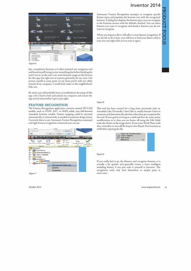
8122019 augi world 2013 10
httpslidepdfcomreaderfullaugi-world-2013-10 1752October 2013 wwwaugiworldcom
Inventor 2014
key a mandatory function as I often initiated one navigation tooland found myself trying to start something else before finishing thetool I was in In the end I see some fantastic usage on the horizonfor this app but right now it is pretty gimmicky for my taste I dopicture myself at some point on my front porch with my tabletinstead of my computer I would look cooler to the neighborhoodkids too
Be aware you will probably have to troubleshoot the setup of thisapp a bit I had to lock and unlock my computer and restart theapp several times before I got it just right
FEATURE RECOGNITIONTe Feature Recognition application converts neutral 3D CAD
models such as SEP SA or IGES solids into full-featuredAutodesk Inventor models Feature mapping could be executedautomatically or interactively as needed to maintain design intentCurrently there is one Automatic Feature Recognition commandand eight feature recognition commands you can use
Automatic Feature Recognition attempts to recognize specificfeature types and populate the browser tree with the recognizedfeatures A dialog box displays the feature types you can recognizein the Features section with the defaults checked You can selectfeatures you want to recognize and deselect features you do notwant to recognize
When you import a file it will offer to start feature recognition Ifyou decide to do it later you will have to find your Base1 solid inyour tree and right click on it to start it again
Tis tool has been around for a long time previously only on
Autodesk Labs Personally I donrsquot like it mainly because I have toconstrain and dimension the sketches when they get recognized bythe tool If your goal is to bring in a solid and then do some minormodifications to it then you are better off using the Edit Solidtools also shown in the image above If you want Work Plane toolsalso remember to turn off the Import into Repair Environment aswell before opening the file
If you really had to go the distance and recognize features it isactually a lot quicker and generally creates a more intelligentmodeling history if you just redo it yourself in Inventor Terecognition tools only lend themselves to simple parts inmost cases
Figure 6
Figure 7
Figure 8
Figure 9
8122019 augi world 2013 10
httpslidepdfcomreaderfullaugi-world-2013-10 1852wwwaugicom October 20
Inventor 2014
PRO
DUCT
FOCUS
WORK FEATURE VISIBILITYTis product allows Inventor users to manage all work featurevisibility in a fast and easy way keeping full awareness of the involvedentities Tis app consists of six buttons on part environment andanother six on assembly environment Inside of part environmenta user can choose to enable or disable the visibility property ofplanes axes or points Inside of assembly environment a user can
also choose on which components to enable or disable the visibilityproperty of planes axes or points
I had a little trouble with this app in the assembly environmentbut that was due to some bad installation files Tis is one appreally worth the $099 How often have you been in an assemblyand not wanted to go back to the part files to turn on and offwork features I recommend ungrouping them so you access bothcommands faster
SHEET METAL FLAT EXPORTTere seems to be a plethora of these apps on the Exchange witheach of them varying in price and options In general the ideabehind these apps is to help automate the process of getting a DXF
to a machine that reads them for manufacturing in a more efficientmanner Tese programs will scan an assembly file and find thesheet metal files on which to perform their routines
Te different variations of this program range from free trialsupwards of $100 for the paid apps I started with one that gave me
a ldquoliterdquo version that would do 20 sheet metal files and I liked it much I started using the full version
FEATURE MIGRATORTe Feature Migrator tool allows Inventor users to more eascreate part features from assembly features User can migraassembly features either by selecting them in the Feature Migratbrowser or by right-clicking on one or several of them and theusing the ldquoSend to Partsrdquo commands Features can also be directmigrated from the regular Inventor model browser using thcontext menu item added by the add-in
Once the operation of migrating features is completed the FeatuMigrator displays a dialog that provides information about thresults Tis first dialog is a ldquohigh-levelrdquo report of the migrationprovides the opportunity for the user to select the action to takfor all the assembly features migrated Suppress if SucceedeSuppress always Delete if Succeeded Delete always or Nothingalso for the part features that havenrsquot been migrated correctSuppress Delete or Nothing Features created by the add-in cbe in an invalid state in the parts for a number of reasons
Te user can also see when a feature is out of date from thassembly and perform updates from the part side
Figure 10
Figure 11
Figure 12
8122019 augi world 2013 10
httpslidepdfcomreaderfullaugi-world-2013-10 1952
8122019 augi world 2013 10
httpslidepdfcomreaderfullaugi-world-2013-10 2052wwwaugicom October 20
Inventor 2014
PRO
DUCT
FOCUS
TIME STAMPime Stamp is an Autodesk Inventor add-in that provides bull A low-cost simple-to-use tool that adds plot time information
to your printsbull A plot stamp that does not dirty the Inventor drawing
documentbull
A simple dockable user interface that keeps out of the way
Te ime Stamp editor lets you size position and orient thestamp relative to the adjacent sheet edges You can include datetime and current user information in the stamp Te time stamponly appears on the plot it does not alter the Inventor drawing
What I really like about this app even though it costs $500 perlicense is that you can find the price yourself and buy it It doeseverything it says it does and it provides an easy-to-use interfacewith an icon that changes based on whether the tool is on or offIf you want even more control over your plot stamping there is amore professional version offered by this company on their websitefor about $4000 a license which will allow more reporting fieldsand more control on the look and location of the stamp
SIMPLE SHEET SETTINGSSimple Sheet Settings combines the existing sheet settings withsome new tools such as changing the title block and also the abilityto make changes to all sheets in a document at once
Instead of first deleting the existing title block from a sheetexpanding the title block folder and inserting the desired titleblock then opening another window to change the sheet size andorientation just click the ldquoSettingsrdquo button located on the Sheetspanel in the Placed Views tab (right next to ldquoNew Sheetrdquo) andhave access to all those options in one location
When the Simple Sheet Settings window is loaded it gathers all the existing title block names and puts them into one drop-dowmenu o change the title block on the current sheet simply selethe desired title block from the drop-down menu and click OKTere is also the ability to change the title block sheet size ansheet orientation to all sheets at one time
Tis is a great little app that saves clicks and only costs a dollaQuite useful and no real setup involved
INTERACTIVE TUTORIALTe Create an Interactive utorial app provides instructions fcreating your own interactive Inventor tutorial Te Guide alincludes how to customize the Welcome Screen to display yointeractive tutorial and add to the ribbon
Tis one definitely falls under the ldquotoo much time on your handuser or CAD admin After reading through the guide on how create the interactive tutorials you find yourself asking the questioldquoWhy donrsquot I just save videos of the process we use in a companserver locationrdquo And that is when you uninstall this app as yohave realized that while it sounded good to you at first there abetter ways to accomplish the goal of company-specific tutoria
and process documentation
Figure 16
Figure 17
8122019 augi world 2013 10
httpslidepdfcomreaderfullaugi-world-2013-10 2152October 2013 wwwaugiworldcom
Inventor 2014
Te tools actually rely on too much externally controlled softwaresuch as Camtasia and other plug-ins and third-party apps to makeit work correctly Save your time and just use Camtasia from
echsmith to do your bidding
KEEPING UP TO DATEWith all these apps it is easy to understand how a user could getbehind on the updates to so many tools With that in mind theExchange Manager found on the ools tab in Inventor will keeptrack of that for you and offer assistance not only in updating butalso uninstalling and specialized help for each app
As a reminder with regard to third-party apps if you startexperiencing undesired effects in Inventor start turning add-ins
off one by one until you isolate which one is giving you fits Properreporting back on the app to the developers makes everyonehappier when the issue gets resolved Tus far I havenrsquot had nearas many issues as I thought I would have
ANY MANY MOREWith 80+ apps currently in the store and about 60 of them ready
for 2014 at the time of this article you should take some time andlook through what is available Tere are apps which are very nicheto the user base as well as those that have you scratching your headover why they are not already part of the core software Below aresome I would write about if I had more room in the article andora fatter PayPal walletbull BOM oolsbull EDM Expressbull Sketch Symbol Librarybull SolidWorks iProperty Importbull Quick Viewsbull 3D Pipebull Point Linkerbull Kwikools
Mark Flayler is an application engi-neer with IMAGINi echnologiesspecializing in manufacturing environ-ments He has implemented Autodeskmanufacturing products within severalindustries including the blowinjectionmolding automotive and custom ma-chinery markets When not providingtraining support and implementationhe writes the IMAGINi Manufac-turing Blog and takes an active role inthe manufacturing community Markis an AC certified instructor and isPSE and AC certified in AutoCADAutoCAD Mechanical AutoCADElectrical Autodesk Data Manage-ment and Autodesk Inventor
Figure 18
Figure 19
8122019 augi world 2013 10
httpslidepdfcomreaderfullaugi-world-2013-10 2252wwwaugicom October 20
SPECIALFEATUREAUGI Forums by Melanie Perr
The AUGI Forums are as always a busyplace Ask a question and you mightsee half a dozen varied methods andworkarounds posted in a single thread If
you have not had any questions yourself I would stilllike to encourage you to pop into the Forums and see
if there are any problems you could solve especially if you use one
of the less adopted products Tere will always be many helpinghands in the AutoCAD and Revit Forums but what about themechanical products or design visualization or structural detailingForums Peek in and see if you can share your experiences andwisdom with the community
I confess that I only scoured the English-speaking Forums forcontent for this article but please keep in mind that there areAUGI Forums available in 12 other languages so users have theoption of asking for support in their native tongue
AUTOCAD ndash SYSTEM VARIABLE
DISCUSSIONhttpbitly15M1hB9
Tis topic started out when a user couldnrsquot delete Te solution wasultimately the PICKFIRS variable but the discussion evolved tosafeguarding other variables automatically just to protect against aloss of settings in the event of a crash User Coloradomrg offeredthe safeguard shown in figure 1
Norton_cad also suggestsDIMLFAC EXPER andBLIPMODE be addedto the list
REVIT ndash
UNDERLAY
BEHAVIOR
EXPLAINEDhttpbitly15M1iFd
Mschroeder opened thediscussion with If you haveever wondered why some wallsdonrsquot show up in underlays or
show up inconsistently from floor to floor or why roofs and vieranges affect their behavior then read on
First rule of underlays Underlay view extent properties (cut rangdepth) are not user modifiable and not coupled to any othviewrsquos properties
Itrsquos also been mentioned ldquoIf objects are visible in the view ranof your current view AND in the view range of your Underlathey are automatically hidden in your underlay so there isnrsquotdouble instancerdquo
Users twiceroadsfool and dbaldacchino helped clarify the effecby posting sample models and pertinent data from the AutodeKnowledgebase and Autodesk Support Visibility View RangDetail Level and Cut Planes are all touched on in this discussioNeed clarity on how to make the most of Underlays Check inthis thread on the Forums
LISP ndash MAKING A DIALOG BOX RETAIN
ITS SELECTIONShttpbitly15JzMCc
Te LISP Forum always has such fascinating topics it is hato decide which to highlight From locking OSNAP options setting Explode options along with troubleshooting of existincode But the discussion surrounding the tutorials and metho
to retain selectioin a dialog box wvaried and lively so had to check it ou r e a v e s 0 4 4 1 3 2 1
even posted a sampdcl file when he wfinished
String Theory
8122019 augi world 2013 10
httpslidepdfcomreaderfullaugi-world-2013-10 2352October 2013 wwwaugiworldcom
AUGI Forums
AUTOCAD ELECTRICAL ndash LINES BEING
LABELED AS WIREShttpbitly1ew9p9D
Dinochrome says that one of his coworkers has reported aproblem with regular AutoCAD lines being labeled as wires
Crosswire35 advises ry checking your wire type edit dialogbox and make sure the ldquomake all lines valid wiresrdquo checkbox is unchecked
And IMCO goes on to say Using the vanilla line command inACADE will still place that line on a wire layer Change your linesto layer 0 and ACADE will not give them a wire number
AUTOCAD STRUCTURAL DETAILING ndash
TUTORIALShttpbitly17kW7cc
Te consensus is that this product is a little confusing to figure outand that most of the tutorials out there are older Most productshave a few videos floating around on Youube but this one doesnot seem to have too many yet
Jpo82 chimes in with I guess only tutorials forthis software are those found at Autodesk websiteTey are for versions 2010 and 2011 but still validhttpusaautodeskcomadskservlet12ampid=13111928 Irsquom not sure but sometimes I feel that the only new feature inASD 2013 is that itrsquos more stable than previous releases
Lucis29 goes on to say Also you might check some movieshttpwwwrobotofficecomasd but they are very old
Spenner then linked to his reporting of the Service Pack andissues it addressed hoping that it addressed some of the issuesthat came up in this discussion
NAVISWORKS ndash IMPROVE ANIMATION
EXPORT QUALITYhttpbitly1fQLoIv
Different methods are discussed from exporting individual imageframes to exporting a video (and how long) but I will leave youwith the following list from Revit For Breakfast
Here are the secrets to movies in Navisworks1 Donrsquot use materials ndash you make your render time much longer2 Use the PNG export option 15fps3 Make your video export twice as long as you need Ten speed it
up for a faux 30fps Tis is faster4 Look up the Navisworks blog by Lee Mullin and Paul Walker
about gooch and phong Tere is your faux render setting5 If you have NW 2012 you wonrsquot have gooch or phong but you
will have better export options 2013 has gooch and Phong butfewer export options
6 Te flickering occurs when multiple shapes overlap If you care
delete them in your export model Sometimes flickering occurs
in the generation of your frames on the PNG export You mayhave a frame that is ldquooffrdquo
7 Set your anti-aliasing to 4x or better on the png export8 Check out my old post httpforumsaugicomshowthread
php132209-Animation-Resolutionampp=1138298ampviewfull=1post1138298
CAD MANAGEMENT ndash NETWORK DRIVE
CHANGED BY IT WITHOUT WARNINGhttpbitly18J4k9c
Blackbox advises edinsmore595165 straight off to utilize theReference Manager program that comes with AutoCAD inorder to reconnect all of the external reference paths that werebroken when the I department upgraded their archaic serversHe further points out that moving from hard pathing to relativepathing would make things easier in the future
Feargt offers another twist Another option which would workon a need only basis when you open the specific drawing Change
XREF and Image paths in drawing to Network path throughscript on a need only basis Basically this will only change pathsPlace this line in a acaddoclsp file(command ldquoscriptrdquo ldquoyourserver and pathXREFREDIRECscrrdquo)and the following in a script fileREDIRB enter name of path to be replacedP enter new path
Tere was also a debate in this thread about obstacles and benefitsof user-managed and I-managed drive mapping
Melanie Perry is a Facilites-Manage-ment Coordinator and echnical Edi-tor in St Louis MO She is the AUGISalary Survey Manager and is curring-ly serving as an Officer on the Board ofDirectors Melanie can be reached atmistressofthedorknessgmailcomor found on witter asMistresDorkness
OTHER HOT TOPICSHave you found a Forum solution so mind-bogglinglyuseful that you leapt out of your chair with a whoopingcheer (or were at least tempted to) Please let me know Asingle person cannot read every post in our bustling AUGIForums so if you would like to see a thread highlighted ina future edition of String Teory feel free to let me knowSend me Wanderer a PM in the Forums or send an emailto MelaniePerryaugicom
See you on the Forums
8122019 augi world 2013 10
httpslidepdfcomreaderfullaugi-world-2013-10 2452wwwaugicom October 20
Revit Architecture 2014
PRO
DUCT
FOCUS
by Martijn de Rie
Myth Buster
Revit amp IFCPart 3
Irsquove given a lot of thought as to how this trilogyof articles should end At first I thought Irsquoduse the Coordination View 20 EXPRESS-GWallPaper for IFC2x3 (httpwwwmdr-
adviesnlwp-contentuploadsCoordinationView_V2-0_WallPaper_IFC2X3_Version-1pdf ) as a stepping stoneto give an ldquoIFC for Dummiesrdquo type of solution But that turnedout to be quite lengthy and rather boring But the link is includedabove for obvious reasonsmdashitrsquos useful
So I went back a little and asked myself ldquoWhy IFCrdquo And with thatquestion the inevitable follow-up immediately appeared ldquoWhynot IFCrdquo I realized that in the previous articles I failed to explainwhy in my humble opinion we should care about this somewhatcrooked badly implemented severe headache-inducing formatTerefore instead of explaining the fundamental technicalities ofIFC that can be explored in other places this final installment willexplore the Why versus Why Not IFC discussion and begin withthe latter
WHY NOT IFCWhen everybody uses Autodeskreg RevitregWell in this case itrsquos a no-brainer Share your Revit files Period
Loss of dataTis is an easier way to share data instead of hacking your wthrough IFC and praying your stuff doesnrsquot get lost in the proce
Even when you manage to export your geometry through IFtherersquos always loss of data
Loss of intelligence during importEven if you only need to send over geometry not data importithat into Revit makes it utterly useless All constraints are locomponent parametrics are gone and so on
Availability of bidirectional linksWhen not everyone uses Revit on a given project (which is quoften when yoursquore not located in the US) why not simply ua bidirectional linking between proprietary software standardTis can be easier and better to control
8122019 augi world 2013 10
httpslidepdfcomreaderfullaugi-world-2013-10 2552October 2013 wwwaugiworldcom
Revit Architecture 2014
WHY IFCWhich may be asked as why would you want to use IFC Or moreaccurately why would you want that option available
Consider what Sir Arthur Conan Doyle wrote ldquoOnce you eliminatethe impossible whatever remains no matter how improbablemust be the truthrdquo
Letrsquos put that to the test shall we
When everybody uses RevitOkay simple math Autodesk has around 7000 employees Teworld has about 72 billion people What are the chances someonenot working for Autodesk has a brilliant idea and creates thesoftware you need tomorrow Tere will always be better solutionsTey might not be viable for you overall but therersquos no reason toshut down access to them Revit is a wonderful generic tool forwhich I see a brilliant future with all kinds of additions for specificniche-markets like AutoCAD has
What about today DDS is MEP-engineering software that cando energy calculations (not simulations) inside your modelRhino lets you model things on the fly that could (arguably)take ages in Revitmdashif you ever get them done ekla lays wasteto the Revit structural rebar functionality any day of the weekwithout breaking a sweat Solibri is a wonderful solution for clashdetection and most importantly rule-based model checking andreportingmdashsomething Revit (or Navisworks) doesnrsquot do
Should I go on
Only problem for all this magnificent software Itrsquos either based onthe IFC format or requires model exchange through IFC
Te fact of the matter is there will always be better softwareAny one may be the software for you but that doesnrsquot mean yourpartners associates etc need to have the choice to use it forcedupon them
Loss of dataOn July 1 2013 there was an extra release for Autodesk softwareTe Sourceforge Open Source IFC Exporter released a new versionthat incorporated the option to map custom Revit parameters(shared or non-shared family or project even calculated values) totheir IFC counterparts
On September 28 2013 I had the honor of showing the secondstep in a complete and controllable data export from Revit
During my RC Europe class I showed the new option to create acustom IFC Property Set and map any given Revit parameter intoIFC fully customizable
IFC does not automatically lead to loss of data Tat idea is simplynot true Incomplete implementation in Revit does lead to loss ofdata As of now you are able to put any piece of data into an IFCeven calculated values And we didnrsquot change the IFC format We
just improved implementation in Revit
Loss of intelligence during importldquoJust because something hasnrsquot happened yet doesnrsquot meanitrsquos impossiblerdquo
I donrsquot know who originally had this insight and I doubt it to bethe movie line I remember but it is true
In the same RC Europe class I showed a native Revit familybeing exported to IFC altered and re-importedmdashwhile keepingall parametric constraints and even adjusting to the alterationsmade directly in the IFC file It is possible but not with thecurrent importer
Availability of bidirectional linksIrsquove been using Revit for almost 10 years now For 4-5 years I didnrsquotknow about IFC at all Before a year ago this was my strongestargument against IFC Why would you need a generic ldquolanguagerdquowith all its limitations (of which there are) weaker implementationand use of parametric capabilities (because it has) and lag-times indevelopment (by nature)
IFC will never be able to do what native software does simplybecause itrsquos responsive in nature Development budgets are afraction of what Autodesk rimble or Nemetschek get to spendon their software
So why not keep it simple and use a bidirectional link Revit has itwith a lot of other Autodesk software and third-party applications
But how long have we waited for them And are they even trulybidirectional Do they exactly do what you want them to do In myhumble opinion the answer to these questions is not very inspiringEven bidirectional links tend to have major limitations and severe
constraints in flexibility And most important Te link itself isalso propriety software No way of adjusting it to your needs
WHAT IF MORE PEOPLE STOPPED
TALKING ABOUT IT AND JUST GOT
INVOLVEDTe improbableFirst off itrsquos a matter of simple logic As Sir Arthur suggested ifwe can successfully check off all likely options to NO want touse IFC doesnrsquot that mean the improbable is true Tat IFC is infact a valuable tool in our toolkit and we should be able to use it
when necessary
Mind you Irsquom not saying you should use IFC If yoursquore on a Revit-only project it would be insane Just send and receive RVs Tefact is this will only be viable for limited parts of the buildinglifecycle If yoursquore lucky the entire design team is on Revit Butmanufacturers have other software facility managers too
As for the design team what if the best structural engineer is not[on Revit] or the MEP guy that has loads of experience in similarprojects Would you settle for second-best just because someoneuses the same brand of tools you do I wouldnrsquot
8122019 augi world 2013 10
httpslidepdfcomreaderfullaugi-world-2013-10 2652wwwaugicom October 20
PRO
DUCT
FOCUS
Revit Architecture 2013
Open AccessWhich brings us to the biggest advantage of IFC (or any open
format) itrsquos open Which means itrsquos adjustable to your needs Nowdonrsquot go ldquothatrsquos too difficult expensiverdquo Tatrsquos bullocks
Te first external enhancement to the Open Source Exporter wascreated by om Pesman a self-employed API specialist
Parametric IFCImplemented by Jon Mirtschin also self-employed IFCparametrics is available Agreed Jon is a well-known IFC guru butstill the point holds
Custom property sets and parametersWim as owner of a small MEP engineering firm hasadded functionalities toward this end and hersquos not even a trueAPI specialist
All these developments were done for free by altruistic volunteerefforts as part of the creation of the Dutch Revit Standards Andof course with the invaluable help of the Autodesk Open SourceIFC Exporter team Angel Velez in particular
But what if these guys actually got paid What if this projectwasnrsquot a Saturday night side-job What if more people stoppedtalking about it and just got involvedmdasheither by themselves or byleveraging experts to get what is needed Te entire IFC format is
Open Source the source code is out there which basically meansyou can do whatever you want and create whatever you needmdasheven on a project-by-project basis
BIM ITrsquoS THE ldquoIrdquo THAT MATTERSIn my humble opinion the entire debate on BIM is focusing on thewrong part of the acronym I donrsquot care if ldquoBuildingrdquo is a noun ora verb Nor do I care whether itrsquos ldquoModelrdquo or ldquoModelingrdquo nor am Icommenting on whether one should say ldquoBIM Modelrdquo
Itrsquos the ldquoIrdquo that matters If wersquore collaborating the Informationis most all I care about I just want your datamdashin the leanest
smartest and most effective way possible
A Revit model will do conversely a lot of times A Revit model w
give me heaps of data I donrsquot want geometry I donrsquot care about ana file format I canrsquot use Now we can all keep on being really anabout it or we can simply use the tools available to us one of thebeing IFC
A FINAL NOTEAs stated at the beginning of the article I really enjoyed writinthis series and for now this is the last of the series But if yoursquointerested in more tips and tricks on IFC let me know I might able to persuade the guys at AUGI to let me write about it againLord knows there is still a lot to talk about regarding IFC
Martijn de Riet is a self-employedBIM Consultant from the Nether-lands working with Revit since version51 Martijn has a bachelor degree inBuilding Science After his studieshe started his own engineering firmworking for contractors architects and
private clients Starting in 2007 hiscompany transformed into a full-timeBIM consultancy service At the mo-ment Martijnrsquos clients vary from mid-sized architectural firms to the largest
dutch General Contracter and MEPEngineering firms with a focus onspecific corporate solutions design andimplementations of Revit and BIMworkflows Martijn is a member ofthe Dutch Revit User Group and cur-rently working on creating a Masteremplate and Component LibraryHe provides lectures for companiestechnical universities seminars etc ona regular basis
Itrsquos the ldquoIrdquo that matters If wersquore collaborating the Information is most all I care about I justwant your datamdashin the leanest smartest and
most effective way possible
8122019 augi world 2013 10
httpslidepdfcomreaderfullaugi-world-2013-10 2752
wwwxicomputercom
8122019 augi world 2013 10
httpslidepdfcomreaderfullaugi-world-2013-10 2852wwwaugicom October 20
3ds Max 2014
PRO
DUCT
FOCUS
by Chris Murra
SUMMARY WHATrsquoS
CUSTOMIZABLE IN MAX
(HIGH LEVEL)When it comes to the customizability of Autodesk 3ds Maxregitrsquos no secret that it can morph itself into whatever you want theprogram to become
Whether yoursquore a modeler animator lighter rigger generalist ortechnical artist 3ds Max can become your own personalized toolbox that is an extension of your own hand in your daily workYou can now combine different command types (such as creatingobjects and object modifiers) into a single menu reducing themouse travel and improving efficiency
In this article wersquore going to take a closer look at one specificaspect of customization with 3ds Max the new enhanced UI Aspart of this article besides taking a deep dive into the operationof this feature I will also be showing how I created the ldquoMographrdquo
tools UI that includes custom buttons and icons At the end this article I will also provide a link to this UI so you can use customize it yourself or share it with others
ENHANCED UI SUMMARYWhat is the Enhanced UI
Te Enhanced UI is a new graphical user interface system thdoes two main things
1) It provides a refreshed 3ds Max user interface with updattool categories and new clusters of pre-existing tools in groupinthat are more akin to their intended purpose as opposed to somtechnical requirement for menu placement
2) It provides a way to allow you the end user to customize thmenu system in almost any way you choose Te drop-down menare ldquotear-ablerdquo (not to be confused with ldquoterriblerdquohellip but I digresand the resulting configurations are savable either by scene or
3ds MaxEssentialsCustomizing
the UI
8122019 augi world 2013 10
httpslidepdfcomreaderfullaugi-world-2013-10 2952October 2013 wwwaugiworldcom
3ds Max 2014
a preset Tey are also distributable and deployable so they can beshared with others
Where is the Enhanced UITe Enhanced UI can be found in the upper left hand corner of themain UI at the very top of the screen Tere is a drop-down menuthat says ldquoWorkspace Defaultrdquo Tis default is the same baselineUI that ships with all 3ds Max installs (Figure 1)
Within the drop-down you can find the ldquoDefault with EnhancedMenusrdquo Tis is the alternative default menu system that youcan use on its own or use as a starting point to create your owncustomized menus
BASIC DEFAULT CUSTOMIZATIONEnhanced UI Customization BasicsNow that wersquove enabled the Enhanced UI how can we change it
SOP Before you begin mucking around with the UI Itrsquos importantto understand what I call the ldquosave-logicrdquo as it pertains to custom UIs
Te UI Save LogicIf you plan on saving this UI for future use there is a specificmethod you must follow to properly save the UI you want and notwreck the default Enhanced UI
Te Save Logic is as follows Itrsquos simple but important
Step 1 urn on Enhanced Default UI (Figure 3)
Step 2 Click ldquoSave as New Workspacerdquo FIRS At this point youwill be prompted for a new name (Figure 4)
Step 3 Edit and change the UI at will
NOE All future edits are ldquoautomatically rememberedrdquo as you go (Iintentionally did not use the word ldquosaverdquo)
Step 4 Te ldquosave as default staterdquo button is important When wehave completed the customization process we then choose thisbutton to ldquolockrdquo in the changes Tis is different than Saving a UIwith a custom name
HO IP ldquoBut this methodology seems backwardrdquo
I can see how yoursquod say that but remember that any changes you make
to any enhanced UI are automatically ldquorememberedrdquo If you create acustom UI then while working you make some temporary changeswhen doing something specific those little changes are automaticallyremembered If you want to return to the default state [of yourcustomized UI] you select ldquoReset to default staterdquo Tis does NObring back the default Max UI rather it brings back the customizedUI you created in ldquolockedrdquo in Step 4
Okay now that you have the save logic down letrsquos begin customizing
1) If you havenrsquot done so already turn on the Default Enhanced UI
2) Go to ldquoManage workspacesrdquo from the drop-down and in the
Figure 1 Workspaces are in the Workspace drop-down menu
Figure 2 Default UI (left) and the Default Enhanced UI (right)
Figure 4 Saving the New UI Workspace
Figure 3 Turning on the Enhanced Default UI
8122019 augi world 2013 10
httpslidepdfcomreaderfullaugi-world-2013-10 3052wwwaugicom October 20
3ds Max 2014
PRO
DUCT
FOCUS
Manage workspaces dialog choose ldquoSave as new Workspacerdquo Giveit a specific name
3) Begin making your desired changes
Since a custom UI is specific to any one individual letrsquos take a lookat what types of customizations can be made
Simple ChangesOne of the simplest things to do is peel off any commandgroup (see Figure 5) Just click the group title bar and drag Tecommand group becomes a floating dialog box Now just becauseyoursquove peeled it off does not mean that yoursquove removed it fromthe drop-down menu Te ldquooriginalrdquo command group remains inthe drop-down You can just close the floating dialog when yoursquoredone with it
Probably the simplest thing you can do is reorganize the menusIn each drop-down menu appears a group of commands You maynotice that some command groups are icons and some are words(Figure 6) o change the appearance of the commands there is asmall icon in the upper right corner of each group of commands(Figure 7)
Te next change is alreally simple Is tcommand group op(expanded) or clos(rolled up) Just clion the plus or minsign in the upper le
corner to set this stafor the next time yolaunch 3ds Max (Figu8) Remember thesettings are saved as yogo so whether it is opor closed is your choicbut the state the menis in when you cloMax is the one that remembered the netime Max opens
What about Saving tDefault state More othis later
Once you have floating menu yocan combine differecommand groups dragging any othcommand group to aother floating dial
that yoursquove created Tis makes for easy creation of custom dialo
based on specific tasks Figure 9 shows a command group fcharacter animationFigure 5 A floating menu that has been torn off the drop-downmenu
Figure 6 The different display states of the menus
Figure 7 Changing menu layouts
Figure 8 Rollouts
8122019 augi world 2013 10
httpslidepdfcomreaderfullaugi-world-2013-10 3152October 2013 wwwaugiworldcom
3ds Max 2014
ADVANCED CUSTOMIZATION
What about completely custom interfaces Herersquos how we do thatwith the Enhanced UI menu system
Te following is the high-level overview of the process Wersquoll thenunpack each step in more detail
If you havenrsquot read the section on Basic default customizationplease do so before continuing Before starting this phase ofcreating your new UI you should have saved your new UI stateTat process is explained in the previous section
1) Create a main drop-down menu (like ldquoMy oolsrdquo)
2) Create a tools category menu into which you will place yourtools (a submenu such as ldquoModeling oolsrdquo or ldquoAnimation oolsrdquo)Drop-downs can have more than one subcategory
3) Add commands to various submenus
4) Clean up the UI by creating custom names adding separatorsor creating custom icons
First letrsquos create a new menu for the menu bar Tis is done easilyfrom the CustomizegtCustomize [Rollout]gtCustomize UserInterface dialog box
Steps for Creating a Drop-Down Menu1) Create a New Menu and give it a name (see Figure 10)
2) Locate your new menu in the Menus window It will be listedalphabetically (Figure 11)
Figure 9 Multiple command groups in one menu
Figure 10 ndash Creating a new drop down menu
Figure 11 Location of new menu
8122019 augi world 2013 10
httpslidepdfcomreaderfullaugi-world-2013-10 3252wwwaugicom October 20
3ds Max 2014
PRO
DUCT
FOCUS
3) Drag your newly created menu category over to the column onthe right Tis will add your new drop-down menu to the interfaceimmediately and you can begin populating it with menu items (seeFigure 12)
UI DESIGN IP Te actual menu name and display name can bedifferent I used a custom menu name behind the scenes so I couldeasily differentiate my menus from the ones created by default or other
tool companies After you create a menu and add it to the right column you can right-click on it and change its display name (see Figure 13)
Next letrsquos create a command group1) Just like in Step 1 from the previous section create a new men
2) Tis time before you drag it to the right column click thplus sign next to your drop-down menu item to expand it Tedrag the new item to the right column dropping it ldquounderrdquo thmenu name
3) Drag any commands from the Commands window on the leto the submenu on the right (see Figure 15)
Herersquos an example from my Mograph ools workspace thshows how a completed menu looks once it is created (Figu16) In the following figure you see both the menu as it appeain the Customize UI dialog and the actual menu (which has bepeeled off)
Notice that some of the commands on the menu are greyed ouTatrsquos because this new menu combines both ldquoObject creatcommands and ldquoObject Modify Commandsrdquo in one menTey will remain grey until you create an object on which thwill be used
Figure 12 Adding the new menu to the UI
Figure 14 Creating a command group
Figure 15 Dragging commands onto the menu
Figure 13 Custom menu names
8122019 augi world 2013 10
httpslidepdfcomreaderfullaugi-world-2013-10 3352October 2013 wwwaugiworldcom
3ds Max 2014
Adding SeparatorsSeparating commands is easy and is recommended to help you oryour intended user make sense of the how the tools are arranged inthe menu Creating a separator is as easy as dragging one over theright column just like a menu or command
HO IP ldquoWhy do I need to create another menu Why canrsquot I addtools right to my menurdquo
Te main reason is that adding a submenu gives you the ability to tearoff the submenu If it werenrsquot in a submenu it wouldnrsquot be tear-ableSo itrsquos really a ldquobest practicesrdquo kind of thing But even if you try to notadd the submenu it will happen automatically Itrsquos important to do it
explicitly so you are aware of what submenus are in the menu and that you are the one in control of what command is going where
CUSTOM ICONSNo custom UI is complete without a custom set of iconsAdditionally not all commands in 3ds Max have their own iconyet But itrsquos important to realize that regardless of how you set up
your UI yoursquore still working within the framework of an existingapplication and there are boundaries to what you can edit andcreate Icons have specific requirements both in their creation(size) location and file name that must be adhered to in order forthem to work properly
SizeformatTe size of icon is pretty simple It must be 32x32 pixels andPNG format
LocationTe location is very specific New icons must be added to thislocation
CProgram FilesAutodesk3ds Max 2014UI_lnResourcesDarkIconsMain
Te new icons I created for the Mograph UI are shown inFigure 17)
Icon File NameIf yoursquore still with me at this point we are now getting into thenether regions of customizing a UI Tis is where things get a littletricky but itrsquos really not too bad File names are specific and aregenerated by the application (3ds Max)
So letrsquos begin First identify the command for which you want aniconmdashusually itrsquos one that doesnrsquot already have an icon But if itdoes and yoursquore changing it MAKE A BACK UP of the originalicon PNG file Tis is because as previously stated you donrsquot havecontrol over the file name Tat means if yoursquore creating your ownicon you need to overwrite the existing one and use its name foryour new icon So back up any original icons
Figure 16 The completed menu
Figure 17 ndash The created icons
8122019 augi world 2013 10
httpslidepdfcomreaderfullaugi-world-2013-10 3452wwwaugicom October 20
3ds Max 2014
PRO
DUCT
FOCUS
It really doesnrsquot matter whether you make the icon first or not ofind the name you need to use you need to navigate as follows
NOE Yoursquore about to edit the ribbon Tere is no need to save thesechanges as we are merely extracting information from it But if yoursquoredoing a lot of custom icon work you may want to save this change to theribbon so you can come back and continue your work in later sessionswithout have to recreate this every time just to get the proper file nameSaving this ribbon is not related to saving your default state of yourUI When yoursquore done creating all your UI icons you can just delete
whatever changes you make to the ribbon
1) Open the ldquoCustomize Ribbonrdquo dialog box
2) Create a new ldquotabrdquo by dragging it onto the ldquoExisting Ucolumn in the middle (see Figure 18)
3) Using the same drag method add a new ldquopanelrdquo to ttemp tab (Figure 19)
4) Now you can get the information you need Find tcommand for which you are creating an icon and dragto the panel
5) Locate the ldquoinfordquo portion of the ldquoPreview Windocolumn At the bottom of the column is the file namneeded to have the icon used properly by the applicati(Figure 20)
CONCLUSIONSo now you know how to create a custom UI scheme f3ds Max 2014 and up By using the Enhanced UI me
system itrsquos really easy to generate a multitude of workspathat allow Max to work the way you want to work
Te example used in this article was the ldquoMographrdquo UI thI created for NAB 2013 If you would like to downloand install it you can get it from my ldquoPinning the Stacblog on the Area herehttpareaautodeskcomblogschrismurray
Enjoy
Chris Murray works for Autodesk
Media amp Entertainment He istrained as an animator (3D variety)but considers himself a creative tech-nologist His daily role is a technicalldquoevangelistrdquo for Autodesk creating marketing deliverables for 3ds Max Heis the author of Mastering 3D StudioMax He has a Masters in Fine Arts(MFA) in Computer Animation fromMiami International University of Artand Design Follow him on witterchrismmurray
Figure 18 Creating a tab on the ribbon
Figure 19 Adding a panel to the tab
Figure 20 Finding the required file name
8122019 augi world 2013 10
httpslidepdfcomreaderfullaugi-world-2013-10 3552
AUGIMembersReach Higherwith ExpandedBenefitsAUGI is introducing three new Membership levelsthat will bring you more benefits than ever beforeEach level will bring you more content and expertiseto share with fellow members plus provide anexpanded more interactive website publicationaccess and much more
MEMBERMEMBER MEMBER
Basic members haveaccess tobull Forums
bullHotNews (last 12 months)
bull AUGIWorld (last 12 months)
DUES Free
Premier members haveaccess tobull Forums
bullHotNews (last 24 months)
bull AUGIWorld (last 24 months)
DUES $25
Professional members haveaccess tobull Forums
bullHotNews (full access)
bull AUGIWorld (full access and in print)
bull ADN 2013 Standard Membership Offer
DUES $100
Are you ready to upgrade yourself and your membership
Access additional benefits and upgrade at wwwaugicom
8122019 augi world 2013 10
httpslidepdfcomreaderfullaugi-world-2013-10 3652wwwaugicom October 20
AutoCAD MEP 2013
PRO
DUCT
FOCUS
by Vladimir Triantafillid
BIM IsWhatrsquos
Driving theIndustry
For the past decade many would arguethat building information modeling(BIM) has metastasized aggressivelythroughout the AEC industry but what
does BIM really mean More importantly whatdoes it do for us and for our industry Ask someone who hasbeen in this industry for more than 25 years or those nearingretirement and yoursquoll find that less than half see its value muchless care to make the effort with its implementation hesequestions mean something different for those who have beenin the industry the past 10-15 years Recent college graduates
however with their tech-savvy capacity and high expectationare eager to implement anything that resembles cutting-edgflashy technology ypical ly they are the ones most receptivenot adamant about putting their talents to use through BIM
I recently gave a BIM presentation with an emphasis on mchanical systems to the summer interns and new hires our companymdashall were non-BIM users except for onemdashbmy presentation did little justice to BIM Half of my audence had found a cure for their insomnia when they realizthis wasnrsquot the latest edition of ldquoCall of Dutyrdquo hat was n
8122019 augi world 2013 10
httpslidepdfcomreaderfullaugi-world-2013-10 3752October 2013 wwwaugiworldcom
AutoCAD MEP 2013
reflection on BIM by any measure Simply put I fell shortof connecting with a potentially captive audience eager toknow what really makes BIM intriguing or how it wouldgive them an edge in the industry I didnrsquot think to look pastpresenting the facts of its processes and benefits o simplyhave stated that proficiency in any of its many facets willpromote a lucrative career would give those still awake theimpetus to jump ship In hindsight the first step I shouldhave taken to begin this presentation was to ask what theywanted to get out of BIM
If you think itrsquos hard conveying the value and splendor ofBIM to receptive and impressionable young minds try toconvince the weathered veterans dead-set in their ldquooldtricksrdquo For every experienced veteran who has converted toBIM there are two ldquoold dogsrdquo that canrsquot shake ldquothe good olrsquodays when we used vellum and light tablesrdquo Guess whatmdashanincreasing amount of naysayers are starting to come aroundincluding those who say theyrsquove been burned by BIM in thepast hey are seeing the simple solutions BIM presents and
how these solutions translate into cost savings More andmore of those who had formerly questioned BIMrsquos utility areconvinced when installation efficiencies are not only real-ized but quantified
Another factor in the evolution of BIM is its tendency toexpand faster than the pace of its general population of us-ers hose of us proud to be catching up to what we think iscutting edge quickly realize it was just another false sense ofaccomplishment as BIMrsquos web continues to grow exponen-tially he solution is rather simple Focus on what you canhandle and always have the presence of mind and sense ofcaution to avoid being overwhelmed by the wake of BIMrsquos
progress herersquos plenty of money to be made and countlessfacets to explore as long we have the following mentality Welive in the information age and those wi lling to share knowl-edge will reap the rewards of communal synergy
On the opposite end of the spectrum you might find ourindustryrsquos opportunists In a hurried frenzy to claim theirspot in the intellectual property queue these opportunistsget carried away with pioneering what they assume is the lat-est improvements to BIM Instead of stopping to absorb anddevelop the benefits of 4D 5D 6D and so on the pioneersare spreading these ldquoDsrdquo thin with abandon further expand-
ing the gap between quality and quantity None of this i s tosay that wersquore heading in the wrong direction On the con-trary letrsquos call it more of a positive economic problemmdashthedemand for BIM expertise and development outweighs thesupply of available users
Fortunately as collegiate curricula catch on to this industrytrend the point of equilibrium will soon follow For as longas I can remember respective companiesrsquo 2D CAD depart-ments have been a significant source as the breeding groundfor potential BIM users While this route hasnrsquot changedregarding the career path of a draftsperson the source poolhas expanded to include architects engineers and construc-
tion managers just to name a few Itrsquos even hard not to noticeits stark demand when BIM and Revit courses are being in-creasingly offered at local community colleges I knew thenthat you didnrsquot necessarily need an undergraduate degreeback when I got my foot in the door of this industry hisprobably wonrsquot hold true in the coming years Still the privi-leged few who are already a part of this industry subset canrely on their experience in this fast-paced market to con-tinue to propel their careers forward ever faster All thesefew need to do is grab onto a small piece of BIMrsquos wing andhang on tight for the ride he fresh-out-of-college e ntrantsmight have a harder time grabbing onto this wing thatrsquos al-ready in motion
o those who are only vaguely famili ar with BIM it is typi-cally perceived as the equivalent of a 3D role-playing videogame In this case itrsquos not difficult to capture a ldquosnapshotrdquoimage of a 3D model shadows cast across random metal ob-
jects taking up space in an orderly fashion between ceil ingspaces and walls What is difficult is conveying the abun-dance of value behind the pretty picture to a client whorsquosonly interested in the pretty picture Who isnrsquot familiar withthe adage ldquoa picture is worth a thousand wordsrdquo Why notchange that saying to ldquoa BIM model is worth five thousandhyperlinksrdquo Now wersquore talking lifec ycles and facilities man-
More and moreof those who had
formerly questioned
BIMrsquos utilityare convinced
when installationefficiencies are notonly realized but
quantified
8122019 augi world 2013 10
httpslidepdfcomreaderfullaugi-world-2013-10 3852wwwaugicom October 20
AutoCAD MEP 2013
PRO
DUCT
FOCUS
agement his supposed video game has suddenly becomean encyclopedia of usable information But wait itrsquos not juststatic information thatrsquos stuck on a DVD on a shelf i n someownerrsquos random storage closet It has now become a livingdynamic source of real-time data Maintenance technicianswill know exactly where to go when the active 3D modelloaded on their laptop highlights a hot water pump needingservice while concurrently bringing up the cut sheets andoperation and maintenance manuals specific to that pumpor system Better still the source of information has shiftedfrom multiple stacks of large drawing sets collecting dust toseveral hundred gigabytes on a hard drive Yes Mrs Clientyour 3D BIM model will be usable for the next 20+ years
Even though you might not necessarily think about i t someof you probably realize that BIM has become the ldquomiddle-manrdquo for so many key components in the construction cyclewell beyond its intermediary role between design and con-struction phases You want to do some significant tenantimprovement in an existing building Laser-scan the exist-ing conditions hatrsquos BIM Is the general contractor rackingtheir brain trying to f igure out where to station the crane forthe project or pave the pathways for delivery trucks Nowtheyrsquore looking to BIM to answer these questions and opti-mize their decisions o take it a step further at which endof the building do we want to load thousands and thousands
of pounds of sheet metal and pipe And then which tradesshould be installing their systems first in any given area ofthe building hatrsquos right wersquore deriving sequencing andtimelines from the BIM model to e stablish the best routes totake while addressing any constructability issues BIM hasbecome the consultant that wears most of the hats Itrsquos ourone-stop shop
I know that Irsquove personified BIM as if itrsquos the brains behindall of its success Letrsquos take a moment to focus instead on itscollaborators or the sum of its integral parts to show thatin reality we are Dr Frankenstein and BIM is our monster
Except in our ca se wersquore beginning to ta me our monster anthose who were previously frightened by it are starting to sthat it indeed is no monster In fact while evolving to domdashand becomemdashgreater things BIM is transforming into aindustry hero he point of convergence is approaching bcause wersquore saving money time and even trees Soon enougBIM will be the industry standard even on the smaller proects Letrsquos keep the pedal to the meta l
You want to know the best news Most of us havenrsquot evebegun to scratch the surface of BIM but wersquore in strategpositions to reap the rewards aking the possibility of ivast potential into account isnrsquot it reassuring knowing th
in these tough economic times wersquore engaged in an industthat has a shortage of well-qualified BIM experts Our eposure alone sets us up for success Now ask yourselves thquestion Is BIM driving our industry or is it the BIM use
Vladimir riantafillidis works for aleading mechanical contractor in theSan Francisco Bay Area with morethan 10 years of experience in the in-dustry Although he has a bachelorrsquosdegree in biology his unique careerchoices have firmly rooted him in a
substantial BIM role awarding himthe opportunity of progressing along-side the relentless evolution of BIMOutside of his career hersquos always opento new adventures whether trying anew cuisine exotic travels or extremesports Te latter adventures have re-cently subsided as the balance of lifehas shifted his focus on spending timewith his growing family
You want to know the best news Most of us havenrsquot
even begun to scratch the surface of BIM but wersquore
in strategic positions to reap the rewards
8122019 augi world 2013 10
httpslidepdfcomreaderfullaugi-world-2013-10 3952
8122019 augi world 2013 10
httpslidepdfcomreaderfullaugi-world-2013-10 4052wwwaugicom October 20
Revit Structure 2014
PRO
DUCT
FOCUS
Streamlining
Sheet Listswith a Custom
Application
In this article we take a brief look a simpleadd-in for Autodeskreg Revitreg named X-Sheetswhich provides tools for incorporating sheetsfrom an AutoCADreg sheet set in a Revit sheet
list ypically this is handled by manually addingplaceholder sheets to the Revit sheet list Tis can be problematicbecause the sheet list becomes disconnected from the sourceand must be updated manually With X-Sheets sheet set datais exported directly from AutoCAD linked to a Revit project
and included in the sheet list by automatically addingupdatinplaceholder sheets For this example all structural scheduleplans elevations and section sheets are in Revit Structure Adetail sheets will be pulled from an external AutoCAD sheet set
X-SHEETS RIBBON PANEL Te first command on our ribbon panel is Discipline Tcommand is used to establish the Revit project parameter twhich the AutoCAD sheet subsets will be mapped For th
by Jonathan Albe
Figure 1 Revit X-Sheets ribbon panel
8122019 augi world 2013 10
httpslidepdfcomreaderfullaugi-world-2013-10 4152October 2013 wwwaugiworldcom
Revit Structure 2014
example we have created a project parameter named My DisciplineParameter Each Revit Structural sheet has been assigned a valueof SRUCURALmdashthe same as the subset name for theAutoCAD detail sheets Te sheet list is grouped and sorted bythis parameter
Te next command on the ribbon panel is Links Tis command isused to establish a link between the Revit project and XML file(s)
containing sheet information exported from AutoCAD You cancreate as many links as needed and use relative paths if required
Te next two commands Sheets and Update do the work ofaddingupdating placeholder sheets to the sheet list While theSheets command allows you to select individual sheets from linksto include in the sheet list the Update command includes all sheetsfrom all links
EXPORT SHEETS FROM AUTOCADFigure 3 shows the AutoCAD X-Sheets ribbon panel and asample sheet set containing structural detail sheets Notice thedetail sheets are grouped under a subset named SRUCURALTis subset name can be exported with each sheet and mapped to
the My Discipline Parameter in Revit Figure 3 shows the ExportSheets dialog with an option to include subset information and theability to exclude individual sheets Selecting the Export buttonprompts us with a dialog to save an XML file to be linked into ourRevit project
Figure 2 Discipline command dialog
Figure 3 AutoCAD X-Sheets ribbon panel and sample sheet set
Figure 4 Export sheets dialog
Figure 5 Export complete
8122019 augi world 2013 10
httpslidepdfcomreaderfullaugi-world-2013-10 4252wwwaugicom October 20
Revit Structure 2014
PRO
DUCT
FOCUS
ESTABLISH LINK TO XML FILE IN REVIT
PROJECTFigure 6 shows the Manage Links dialog A link has been added tothe XML file we generated when exporting sheets from AutoCADNotice there is an option to make the link path relative to our
Revit Project location
IMPORT SHEETS FROM XML LINKFigure 7 shows the Revit Structure sheet list before any sheetshave been imported from AutoCAD After selecting the Sheetscommand we are prompted with a Manage Sheets dialog
For this example we have selected all sheets from the XML linto include in our sheet list After confirming the dialog neplaceholder sheets are immediately added to the sheet list angrouped according to the SubsetDiscipline mapping Te neplaceholder sheets are identified behind the scenes as being relatto the X-Sheets XML link for later updating
Figure 6 Manage Links dialog
Figure 9 Sheet list after import
Figure 7 Sheet list before import
Figure 8 Manage Sheets dialog
The X-Sheets
add-in is a great tool
for incorporating
AutoCAD sheets into
a Revit sheet list
8122019 augi world 2013 10
httpslidepdfcomreaderfullaugi-world-2013-10 4352October 2013 wwwaugiworldcom
Revit Structure 2014
UPDATE SHEETSFigure 10 shows the Export Sheets dialog in AutoCAD afterdetail sheets have been renumbered to include ldquo-Ardquo When changesare made to AutoCAD sheets the original export steps must befollowed to replace the XML file linked to our Revit project Oncethe XML has been replaced simply run the Update command inRevit to update the sheet list
SUMMARYTe X-Sheets add-in is a great tool for incorporating AutoCADsheets into a Revit sheet list Te add-in saves time by automatically
adding placeholder sheets eliminates room for error in manualtranslation and helps to keep your sheet list up to date withminimal effort
Jonathan Albert is co-founder of BIM- pulse echnologies LLC amp SeniorApplications Developer at LindemanBentzon Bojack Engineering in Cler-mont Florida He has worked morethan 15 years implementing and usingBIM echnology for some of the na-tionrsquos leading production home build-
ers Most recently he has developedBIMpulse an Options Managementand Material akeoff Add-In for Au-toCAD Architecture Revit and Au-todesk Design Review Jonathan can bereached at jonalbbecom
Figure 10 Export Sheets dialog after sheet renumber
Figure 11 Update complete
Figure 12 Sheet list after update
The X-Sheets
add-in is agreat tool for
incorporatingAutoCAD
sheets intoa Revit
sheet list
8122019 augi world 2013 10
httpslidepdfcomreaderfullaugi-world-2013-10 4452wwwaugicom October 20
AutoCAD Civil 3D 2014
PRO
DUCT
FOCUS
by Tench Tilghma
Itrsquos a fact Jack You invested money in the worldrsquosmost popular civil engineering and designsoftware You (or someone else) will have workhard to make the software run productively
and publish the engineering design or surveywork acceptably
Every AutoCADreg Civil 3Dreg user will tell you ldquoYou need a Civil3D templaterdquo
heyrsquore right sort of You need more than one he suppliedexample Autodesk template files (dwt) are just thatmdashexamplesto show you that things are possible A great many ldquothingsrdquo arepossible in Civil 3D It is data-centric model-based software Asa dedicated content developer and continuous customizer of Civil3D I hope the following perspectives and tips help shorten thecycles and reduce the pain of customizing the software
AutoCAD Civil 3D was constructed from the ground up todisconnect the survey and engineering data from how that missioncritical data is represented
WITH LIBERTY COMES RESPONSIBILITYAs far as Autodesk is concerned what you want the many Civil 3Dldquothingsrdquo to look like and how the Civil 3D data is to be annotated istotally up to you hatrsquos not really true is it Plan sets are publishedin arcane symbolic graphic languages designed to faithfully conveythe design intent to someone who must build it with a plan checkeror two (or three or four) stuck in between
As a professional I prefer to call them ldquoPlan Set Languagesrdquo hhelps focus the development to the publishing of Civil 3D datMost people throw a fuzzy word around this complex mix human perceptive agendas and call that ldquoCAD Standardsrdquo
ldquohe wonderful thing about standards is there are so many of themndash Grace Hopper et al
PICK A STANDARD AND MANAGE BY ITldquoWe already have a CAD standardrdquo his may be the first anworst Civil 3D customization mistake any skilled AutoCAD usor organization can make he odds are the CAD standards yoemployed before do not take into account the data centric anmodel-based methods that Civil 3D employs Simply put Civ3D manages how things look and behave by Style Primitive-basAutoCADreg standards may get in the way
Older ldquoCADrdquo standards by definition must be focused on CAprimitive publishing specifics layer textstyle (height) blo
CustomizeCorrectly
Figure 1 Standards documentation is required
8122019 augi world 2013 10
httpslidepdfcomreaderfullaugi-world-2013-10 4552October 2013 wwwaugiworldcom
AutoCAD Civil 3D 2014
graphics standards and so on In raw AutoCAD and AutoCAD-based drafting and design software the only way to manage all theCAD primitive stuff was to be SPECIFIC about all the details allthe time he drawing we create and check things in is the drawingwe publish
If you publish work out of quality control or design drawingsin Civil 3D this is a sign you may be missing some of its timesaving advantages
While the old CADD process works it requires a lot of man-hoursdedicated to maintaining and checking the details Clearly one ofCivil 3Drsquos critical design development goals is to rid organizationsand Civil 3D users of this expensive man-hour burden and costhe idea here is to put the man-hours into the iterative engineeringprocess instead Civil 3D Feature data and Style make this possible
Civil 3D styles and label styles do employ the AutoCAD layertextstyle block references AutoCAD customizers are used tohe software is still called ldquoAutoCADrdquo Civil 3D after all Our
AutoCAD customization skills still apply But we must applythem differently and much more systematically Herersquos whyhellip
YOU NAME ITmdashTHE MOST CRITICAL
STANDARDCivil 3D Styles and label styles employ (reference) the AutoCADldquonamedrdquo parts to ldquoexpressrdquo themselves Style tools just look for andmatch the ldquorightrdquo names Change the ldquomeaningrdquo andor definitionof the names and you can change anything
We call this fundamental property and benefit of object-orientedprogramming the Power of Names In programming speak this
concept and practical reality is called a ldquonamespacerdquo
Such a namespace in engineering speak answers the questionldquoIn this context does ldquoDIrdquo means a ldquodrop inletrdquo In a minute wersquollget to the structure of a customization ldquonamespacerdquo for Civil 3DAutoCAD references
THE POWER OF NAMESGo ahead and make a drawing from your current Civil 3D templateoss in some Civil 3D data by data reference from any projectUse the RENAME command on any of the old AutoCAD stylecollectionsmdashtry layers
Rename like crazy Your existing Civil 3D styles and label styles willhappily work exactly the same he components in the Civil3DFeature and Label Styles will go to your renamed layers Becauseyou didnrsquot change the properties of the layers either nothingchanges Itrsquos not too exciting until you think about what it means
FOLLOW A SCRIPTObviously as customizers we never want to do this sort of workmanually Computers are faster better and more exact typists thanwe are We commonly rely on AutoCAD scripts generated from
Microsoft Excel spreadsheets (See the end of the article)
here are a couple of key collections in the object model thatCivil 3D walls off from this form of potentially destructiveuser madnessmdashObject Properties in Drawing Settings and afew things like Figure Prefix Dbs values that are not ever in thedrawing per se
WHAT REALLY MATTERSAutoCAD Civil 3D style is mind-boggling abstraction Everythingis designed and built to point at references We can employ styleabstraction for our benefit
In one sense AutoCAD Civil 3D style doesnrsquot care aboutAutoCAD layer standards block libraries textstyles colorsplotstyles or really anything else AutoCAD From our perspectiveall the Civil 3D styles care about are the arbitrary and exact namesthey currently reference
he Civil 3D customizerrsquos dilemma Keep book on the exactnames here are a lot of names to keep track of You must havea plan You must have rules You must employ the same processesconsistently in the same order to get quality assured results
Figure 2 Are description keys a namespace
Figure 3 Rename the AutoCAD reference names
8122019 augi world 2013 10
httpslidepdfcomreaderfullaugi-world-2013-10 4652wwwaugicom October 20
AutoCAD Civil 3D 2014
PRO
DUCT
FOCUS
hat Current word is a wonderfully relative term forthe customizer
Build a set of styles extract them to another drawing rename andor redefine the references and quickly produce a different resulthe Current method makes it easy to propagate success andmistake It makes it repetitively tedious to make fixes
NO CAN STOPAs innovative content developers for Civil 3D we chose to employthe National CAD Standard (NCS) as our fundamental Namestandard Not because we like the NCS but because of all thehard-won experience expressed in these tested standards Inmany respects we employ the NCS UDS (Uniform DrawingStandards) etc in our Production Solution products becauseof the underlying How and Why for those standards and theirpractical published Rules
We want to build faster high-performance vehicles Why reinventthe wheel when we can improve on it
STANDARD KEYS TO NAMEShe NCS employs a hierarchical concept of Keys here areMajor Keys Minor Keys etc that have order precedence and aninterpreted meaning he NCS Layer standard employs the Key-based rules to produce defined meanings to Layers
You can in practice employ the same Layer Keys to be genericor granularly specific about where the published results go Allthe annotation can go to one layer or many different layers forexample Styles andor sets do the work
his KEY CODE structure produces a flexible and structuredldquonamespacerdquo we referred to earlier Itrsquos a namespace that both thesoftware can employ and is relatively easy for us dumb-bunnyhumans to learn to decode when we must Most of the time theusers donrsquot and shouldnrsquot care anyway
Figure 4 shows a few of the NCS ldquolikerdquo Keys we employ in ourproducts We employ them for both layer and block collectionsand even the structure of libraries hey may even be employedin Civil 3D style names when thatrsquos appropriate (See the endof the article)
he customizing key point is that the meanings of these specificKeys can be translated into any other set (or sets) of different
Keys he Key changes can be systematically applied to whatevAutoCAD reference tables and resources we require
he results of any changes will float uphill to the named Civil 3Styles we choose to employ hink of all the AutoCAD referencin a template as a Set
BEYOND AUTOCADNow wersquove looped back to Civil 3D style tools and substantivetheir names and what their parts refer to Welcome to the circuland iterative world that is customizing and employing Civil 3D
Aside from the requisite customization skills and experience build style tools our practical biggest customization issues afrankly Civil 3D human interface issues
No matter how you cut it you have a very limited amount of tespace to help users decide on the ldquorightrdquo style tool to use he teof the style toolrsquos name is all you get to deliver to the user ypicaitrsquos a pick box list
You might get lucky and have the Style Viewer but that Viewcannot represent everything a style can do
FEATURE STYLES NAMESWhat we call the ldquoFeature Stylesrdquo (the Ci3D Featurersquos graphics) require that our stynames explain in simple readable humterms what the tool does For examplesurface style like ldquoContours 1-5 Proposed
Figure 4 Some standard keys
Figure 5 The limitations of user style choice
8122019 augi world 2013 10
httpslidepdfcomreaderfullaugi-world-2013-10 4752October 2013 wwwaugiworldcom
AutoCAD Civil 3D 2014
For the common and most understood features this makes somesense ASCII order rules how named Styles organize Names mustsort that out
Complex graphic features such as Views have a lot more going onldquoMy Standard Profile Viewrdquo doesnrsquot cut it except in a publishingtemplate he style names must be more informative and specificDoes the Profile View include grid lines or not We must recognizethat the engineering data behind what we want to visualize isvariable and the user will have specific needs to get work doneWhen you check a surface you need to see the data in differentways than when the result is published
Choice of style is productive Choice is not contrary to publishingstandards unless you mix the two
LABEL STYLE NAME FACTORSWhen we open the Alignment Label Style collection andorstart to assemble Sets of Label Styles we see any hope of namesimplicity for label styles disappears in a flash
he majority of styles are annotative here are a lot of formsand specific types of them Label Style ype matters he smartcustomizer employs the Label Style Default (LSD) hierarchyexpressed in the oolspacegtgtSettings tab or ignores it and missesthe benefits
Label styles often must have a geometric framework to themItrsquos about ldquoreadabilityrdquo and meaning Whether this label goes upor down or attaches here and not there is critical to annotativeclarity he graphic structure of many data-rich label styles alsofundamentally matters to the stylersquos upgrade stability herersquos
a maintenance cost to pay if you refuse to employ consistentgeometric structures in label styles
CUSTOM USAGECan users see the right data and at the right time Will the useremploy a general alignment parcel or figure line and curve labelHow do they see the difference in a simple list It is easy to misshow ldquoon-the-flyrdquo annotative information negatively or positivelyeffects design time decision making and quality control Peoplewill make things to get the job done Do you fight it or enable ithe Simple Style Rules anyone can learn
THE CIVIL 3D NAMESPACESA Civil 3D style naming convention must be human readablecreate order in the interface and therefore include a rule-basedeasy-to-learn code system that expresses quickly the critical detailso customize we need two namespaces One for the top-end stylesand one for the back-end AutoCAD references In productionprojects we need a third namespace for how we name the featuresbut thatrsquos another story
his client and this project demand these CAD standards specificsAnother client and project demand something different Even ifyou donrsquot believe you regularly face that common problem you
still have to improve the internal production templates themselveshe method and process arenrsquot different
In our project-based production world Civil 3D users andsupervisory staff can always work with the familiar and publishwhat is demanded in a customized publishing template hetwo-pronged project template approach has the added benefit ofpotentially quantifying the costs and real return on investment forthe customization itself
CUSTOMIZE TO PUBLISH ON DEMANDIn practical terms we can change the expressed graphicsmdashthe PlanSet Language (CAD standards) with managed intern level staffEven non-CAD people can see and identify graphic differenceOnly basic AutoCAD and basic spreadsheets skills are requiredfor much of the work if you have a naming plan ldquoChange thatmanhole block to look like this manhole blockrdquo Your ldquothatrdquo mustbe specific
ldquoPublish on demandrdquo capability is a productivity and competitive
advantage but it takes repetitions to develop and practice the skillsWe must endlessly customize Civil 3Dmdashreap the benefits
CIVIL 3D NAME RESOURCEShe Standard Keys the NCS-like AutoCAD reference namespacehe Jump Standards includes the detailed and documented stylenamespace Find them at wwwcadpilotcomresourcesaspx
Excel Cell Formula Script ExampleHerersquos the pseudo code for a typical formula-based layer script thatmakes a layer table with all the details filled in from a cell It createsa series of quote wrapped strings when a column of such cells is
copied and pasted to an ASCII text file
ltLayerCommandgtampCHAR(13)amprdquoSrdquoampCHAR(13)ampltOldLayergtampCHAR(13)amprdquoRrdquoampCHAR(13)ampltNewLayergtampCHAR(13)ampltNewLayergtampCHAR(13)amprdquoCrdquoampCHAR(13)ampltColorgtampCHAR(13)ampCHAR(13)amprdquoLWrdquoampCHAR(13)ampltLineweightgtampCHAR(13)ampCHAR(13)amprdquoPSrdquoampCHAR(13)ampltPlotstylegtampCHAR(13)ampCHAR(13)amprdquoDrdquoampCHAR(13)ampltDescriptiongtampCHAR(13)ampltNewLayergtampCHAR(13)
ench ilghman is President ofMoreCompetency Inc an Autodesk
Developer Partner specializing in in-novative Civil 3D Production Solu-tion products and consulting services
for AutoCAD Civil 3D ench is aregular speaker at Autodesk Univer-sity and AEC industry events on thetopics of technology adoption innova-tion and (his personal favorite) peopleskills He posts on the Get the Jump onCivil 3D blog
8122019 augi world 2013 10
httpslidepdfcomreaderfullaugi-world-2013-10 4852wwwaugicom October 20
Revit MEP 2014
PRO
DUCT
FOCUS
by Todd Shackelfor
W
hen any new technology hits theground there are plenty of false startsand backtracking In time shortcutsare found tricks of the trade are
discovered and best practices are defined So is thecase with Autodeskreg Revitreg even for MEP users his article willoutline a logical roadmap of technical and non-technical mustdorsquos and donrsquot dorsquos for transitioning to Revit MEP From settingexpectations defining goals and plotting in Revit to addressingBIM IPD and VDC the checklist of elements required to helpRevit really work in an office will be covered Every implementationwill come with resistance workflow issues and plenty of headachesbut staying on course and hitting the important milestones alongthe way will help reduce stress of something akin to the craziestfamily trip ever
FIRST CONSIDERATIONS ndash SOFTWAREOne might think it is all about Revit he truth is that Revit reallywants to act as a central location for data that is constantly on themove Much like a smartphone leverages the power of thousandsof applications Revit plugs into workflows with more than a fewAutodesk programs as well as a host of third-party programs hesimple fact that the Building Design Suite comes with so manyvaried applications is a pretty big hint that Revit wants to play ona team Firms need to look at their processes from a high level andlook for the best workflows and programs for the team
FIRST CONSIDERATIONS ndash HARDWAREEvaluate the PCs and know what their capabilities are anknow what Revit requires Search Autodeskrsquos website for systerequirements for Revit products Requirements for three tieof deployment are listed for systems covering an entry-levconfiguration a balanced performance configuration and performance configuration Certified and supported graphi
hardware is also accessible from this page he non-hardwasavvy should seek input from an I professional Revit cannand will not perform on outdated or entry-level PCs and thperson leading the implementation usually takes the blame wheexpectations fall short Best advice is overkill it on hardware Whseems over the top today is inadequate in a year
FIRST CONSIDERATIONS ndash TRAININGhere is no way to get around the fact that training will need tbe done Even if every person in the firm has already used Revtraining on using Revit company standards must still take plachere are many ways to deliver training An in-house expe
TransitionRoadmap
8122019 augi world 2013 10
httpslidepdfcomreaderfullaugi-world-2013-10 4952October 2013 wwwaugiworldcom
Revit MEP 2014
can provide just-in-time all the time Autodesk resellers andconsultants typically provide three- to five-day immersion trainingand short- to long-term consulting here are countless web-based training optionsmdashfree and paid Community colleges thatoffer Revit training usually require a final project that will putstudents through the paces and better entrench the
knowledge and skills
On the down side Revit MEP-specific classes areall but impossible to find Lastly the extreme go-getter can buy a book and learn on the job In realityeveryone learns differently and being preparedto leverage all these types of training is the bestsolution People will gravitate to the solution thatworks best for them when it is provided
FIRST CONSIDERATIONS ndash
LINE UP YOUR DUCTS (UGH hellip
DUCKS)Set appropriate goals based on the size of thefirm Small medium and large firms will havedrastically different goals and timelines It mightseem odd but small firms have the upper hand inadopting new technologies and processes hinkabout it What is easiermdashgetting 3 people toagree or 300 Recognize that an AE firm will havecompletely different goals and processes than a solely MEP firmDuring any shift in process be prepared to support the old andnew at the same time and sometimes in the same project hiswill mean keeping symbols in Revit as close as possible to symbols
in AutoCADreg Consider how quality reviews are done and clientexpectations When things look different it is an impediment tochange Minimizing the impediments will help tremendously
All that being said communication is the real key to most everyprojectrsquos success It is important keep information flowing upand down the chain and set the expectations early Some criticalexpectations for this type of implementation are that things will gowrong things will take longer things will look different things willhave to change and things will continue to evolve Remind usersand management of the progress they have been made by trackingand documenting incremental goals
With a general direction and expectations set itrsquos time to get morespecific about the journey his trip is a long one and a phasedapproach is best Firms can tailor the following phasing to suitindividual needs his example has four phasesmdasheach with itsown goals building off the previous phases
Phase 1 - Goals1 Create construction documents2 Improved collaboration3 Interference mitigationo obtain these goals the following Revit items need to be addressedhe first group addresses the goal of good construction documentshe second group deals with process and keeping things standardhe space available in this article doesnrsquot allow for ldquoHow torsquosrdquo foreach item but each is well documented in the Revit help pageand all over the Internet Get a couple points of view and marrythe possibilities to the culture and needs of the firm in question
bull Line styles createdbull Fonts set for plan text titles title blocks tags and everything
elsebull Object styles ndash Define the weight color tone and transparency
of everything bull Incorporation of standard detailsbull Browser organization ndash Decide how you want to see views
organizedbull Filters ndash Know if you need standard filters and create them
ahead of timebull Phasesbull View templatesbull Project templatebull Duct Stylesbull Pipe stylesbull Family creation
Figure 1
Figure 2
8122019 augi world 2013 10
httpslidepdfcomreaderfullaugi-world-2013-10 5052
8122019 augi world 2013 10
httpslidepdfcomreaderfullaugi-world-2013-10 5152October 2013 wwwaugiworldcom
Inside Track
CSCrsquos Integratorhttpwwwcscworldcom
Integrator is a tool that allows you to synchronize structural designscreated in CSCrsquos Fastrak Building Designer (steel building designsoftware) and Orion (structural concrete building design software)with Autodeskreg Revitreg 2014
ldquoLeading structural software provider CSC has released a new versionof Integrator its market leading Structural BIM integration softwarefor synchronizing code-compliant models produced in CSCrsquos buildingdesign software Fastrak and Orion with Autodeskreg Revitreg Nowfully compatible with Autodesk Revit 2014 structural engineers andtechnicians have even greater control during the integration process
Using Integrator full and part models can be synchronized betweenFastrak or Orion and Autodesk Revit with the ability to manageadded deleted and modified members and their associated
design datardquo
BiMTOOLShttpwwwsofistikcom
BiMOOLS is a set of productivity tools that are designed forAutodeskreg Revitreg 2014 Te plug-in can be installed from theAutodesk Exchange Apps store
ldquoTe first international version of the SOFiSiK BiMOOLS isnow available SOFiSiK BiMOOLS is a collection of free tools forAutodeskreg Revitreg Structure to enhance the productivity up to 50Te features range from easy font type substitution and automaticgeneration of dimensional lines over the automatic positioning ofstructural elements to the comprehensive Family Creator to generatefamilies of eg beams braces and columns for optimal communicationwith FE analysis tools like the SOFiSiK softwarerdquo
Find further information and download links for Revit 2012 and
2013 on the dedicated BiMOOLS website
Autodesk AutoCAD 360 21httpswwwautocad360com
Autodeskreg AutoCADreg 360 is a mobile and web-based application that allows you to view editand share drawing files created with AutoCADand AutoCAD-based products Te mobile appis available from the Apple iunes App Store andGoogle Play Store
ldquoAutoCAD 360 is a free easy-to-use drawing and drafting mobileapp that allows you to view edit and share AutoCAD drawingsmdashanytime anywhere Simplify site visits and fieldwork with powerfuldesign review and markup toolsmdashavailable online and offline
Seamlessly share drawings with others across desktop web andmobile devices Easily access drawings from web browsers using
the free companion AutoCAD 360 web app AutoCAD 360Pro subscription plans further expand the functionality of
the app bringing additional capabilities to the fieldrdquo
Te updates that are in this latest release arebull Stunning high-resolution drawings display
via full retina supportbull Better display through improved PDF
supportbull Easy switching between metric and imperial
unitsbull Saves time with faster app loading bull Improved collaboration through in-app
notifications and streamlined sharing bull New properties for Properties Palette
(Pro version)
AUGIWorldbrings
you recentdevelopmentsin Autodeskand AEC-relatedsoftwareitems
Until next issue
If you have some news to share with us for future issues please let usknow Likewise if you are a user of a featured product or news itemand would like to write a review we want to know
By Lee Ambrosius
8122019 augi world 2013 10
httpslidepdfcomreaderfullaugi-world-2013-10 5252
8122019 augi world 2013 10
httpslidepdfcomreaderfullaugi-world-2013-10 1852wwwaugicom October 20
Inventor 2014
PRO
DUCT
FOCUS
WORK FEATURE VISIBILITYTis product allows Inventor users to manage all work featurevisibility in a fast and easy way keeping full awareness of the involvedentities Tis app consists of six buttons on part environment andanother six on assembly environment Inside of part environmenta user can choose to enable or disable the visibility property ofplanes axes or points Inside of assembly environment a user can
also choose on which components to enable or disable the visibilityproperty of planes axes or points
I had a little trouble with this app in the assembly environmentbut that was due to some bad installation files Tis is one appreally worth the $099 How often have you been in an assemblyand not wanted to go back to the part files to turn on and offwork features I recommend ungrouping them so you access bothcommands faster
SHEET METAL FLAT EXPORTTere seems to be a plethora of these apps on the Exchange witheach of them varying in price and options In general the ideabehind these apps is to help automate the process of getting a DXF
to a machine that reads them for manufacturing in a more efficientmanner Tese programs will scan an assembly file and find thesheet metal files on which to perform their routines
Te different variations of this program range from free trialsupwards of $100 for the paid apps I started with one that gave me
a ldquoliterdquo version that would do 20 sheet metal files and I liked it much I started using the full version
FEATURE MIGRATORTe Feature Migrator tool allows Inventor users to more eascreate part features from assembly features User can migraassembly features either by selecting them in the Feature Migratbrowser or by right-clicking on one or several of them and theusing the ldquoSend to Partsrdquo commands Features can also be directmigrated from the regular Inventor model browser using thcontext menu item added by the add-in
Once the operation of migrating features is completed the FeatuMigrator displays a dialog that provides information about thresults Tis first dialog is a ldquohigh-levelrdquo report of the migrationprovides the opportunity for the user to select the action to takfor all the assembly features migrated Suppress if SucceedeSuppress always Delete if Succeeded Delete always or Nothingalso for the part features that havenrsquot been migrated correctSuppress Delete or Nothing Features created by the add-in cbe in an invalid state in the parts for a number of reasons
Te user can also see when a feature is out of date from thassembly and perform updates from the part side
Figure 10
Figure 11
Figure 12
8122019 augi world 2013 10
httpslidepdfcomreaderfullaugi-world-2013-10 1952
8122019 augi world 2013 10
httpslidepdfcomreaderfullaugi-world-2013-10 2052wwwaugicom October 20
Inventor 2014
PRO
DUCT
FOCUS
TIME STAMPime Stamp is an Autodesk Inventor add-in that provides bull A low-cost simple-to-use tool that adds plot time information
to your printsbull A plot stamp that does not dirty the Inventor drawing
documentbull
A simple dockable user interface that keeps out of the way
Te ime Stamp editor lets you size position and orient thestamp relative to the adjacent sheet edges You can include datetime and current user information in the stamp Te time stamponly appears on the plot it does not alter the Inventor drawing
What I really like about this app even though it costs $500 perlicense is that you can find the price yourself and buy it It doeseverything it says it does and it provides an easy-to-use interfacewith an icon that changes based on whether the tool is on or offIf you want even more control over your plot stamping there is amore professional version offered by this company on their websitefor about $4000 a license which will allow more reporting fieldsand more control on the look and location of the stamp
SIMPLE SHEET SETTINGSSimple Sheet Settings combines the existing sheet settings withsome new tools such as changing the title block and also the abilityto make changes to all sheets in a document at once
Instead of first deleting the existing title block from a sheetexpanding the title block folder and inserting the desired titleblock then opening another window to change the sheet size andorientation just click the ldquoSettingsrdquo button located on the Sheetspanel in the Placed Views tab (right next to ldquoNew Sheetrdquo) andhave access to all those options in one location
When the Simple Sheet Settings window is loaded it gathers all the existing title block names and puts them into one drop-dowmenu o change the title block on the current sheet simply selethe desired title block from the drop-down menu and click OKTere is also the ability to change the title block sheet size ansheet orientation to all sheets at one time
Tis is a great little app that saves clicks and only costs a dollaQuite useful and no real setup involved
INTERACTIVE TUTORIALTe Create an Interactive utorial app provides instructions fcreating your own interactive Inventor tutorial Te Guide alincludes how to customize the Welcome Screen to display yointeractive tutorial and add to the ribbon
Tis one definitely falls under the ldquotoo much time on your handuser or CAD admin After reading through the guide on how create the interactive tutorials you find yourself asking the questioldquoWhy donrsquot I just save videos of the process we use in a companserver locationrdquo And that is when you uninstall this app as yohave realized that while it sounded good to you at first there abetter ways to accomplish the goal of company-specific tutoria
and process documentation
Figure 16
Figure 17
8122019 augi world 2013 10
httpslidepdfcomreaderfullaugi-world-2013-10 2152October 2013 wwwaugiworldcom
Inventor 2014
Te tools actually rely on too much externally controlled softwaresuch as Camtasia and other plug-ins and third-party apps to makeit work correctly Save your time and just use Camtasia from
echsmith to do your bidding
KEEPING UP TO DATEWith all these apps it is easy to understand how a user could getbehind on the updates to so many tools With that in mind theExchange Manager found on the ools tab in Inventor will keeptrack of that for you and offer assistance not only in updating butalso uninstalling and specialized help for each app
As a reminder with regard to third-party apps if you startexperiencing undesired effects in Inventor start turning add-ins
off one by one until you isolate which one is giving you fits Properreporting back on the app to the developers makes everyonehappier when the issue gets resolved Tus far I havenrsquot had nearas many issues as I thought I would have
ANY MANY MOREWith 80+ apps currently in the store and about 60 of them ready
for 2014 at the time of this article you should take some time andlook through what is available Tere are apps which are very nicheto the user base as well as those that have you scratching your headover why they are not already part of the core software Below aresome I would write about if I had more room in the article andora fatter PayPal walletbull BOM oolsbull EDM Expressbull Sketch Symbol Librarybull SolidWorks iProperty Importbull Quick Viewsbull 3D Pipebull Point Linkerbull Kwikools
Mark Flayler is an application engi-neer with IMAGINi echnologiesspecializing in manufacturing environ-ments He has implemented Autodeskmanufacturing products within severalindustries including the blowinjectionmolding automotive and custom ma-chinery markets When not providingtraining support and implementationhe writes the IMAGINi Manufac-turing Blog and takes an active role inthe manufacturing community Markis an AC certified instructor and isPSE and AC certified in AutoCADAutoCAD Mechanical AutoCADElectrical Autodesk Data Manage-ment and Autodesk Inventor
Figure 18
Figure 19
8122019 augi world 2013 10
httpslidepdfcomreaderfullaugi-world-2013-10 2252wwwaugicom October 20
SPECIALFEATUREAUGI Forums by Melanie Perr
The AUGI Forums are as always a busyplace Ask a question and you mightsee half a dozen varied methods andworkarounds posted in a single thread If
you have not had any questions yourself I would stilllike to encourage you to pop into the Forums and see
if there are any problems you could solve especially if you use one
of the less adopted products Tere will always be many helpinghands in the AutoCAD and Revit Forums but what about themechanical products or design visualization or structural detailingForums Peek in and see if you can share your experiences andwisdom with the community
I confess that I only scoured the English-speaking Forums forcontent for this article but please keep in mind that there areAUGI Forums available in 12 other languages so users have theoption of asking for support in their native tongue
AUTOCAD ndash SYSTEM VARIABLE
DISCUSSIONhttpbitly15M1hB9
Tis topic started out when a user couldnrsquot delete Te solution wasultimately the PICKFIRS variable but the discussion evolved tosafeguarding other variables automatically just to protect against aloss of settings in the event of a crash User Coloradomrg offeredthe safeguard shown in figure 1
Norton_cad also suggestsDIMLFAC EXPER andBLIPMODE be addedto the list
REVIT ndash
UNDERLAY
BEHAVIOR
EXPLAINEDhttpbitly15M1iFd
Mschroeder opened thediscussion with If you haveever wondered why some wallsdonrsquot show up in underlays or
show up inconsistently from floor to floor or why roofs and vieranges affect their behavior then read on
First rule of underlays Underlay view extent properties (cut rangdepth) are not user modifiable and not coupled to any othviewrsquos properties
Itrsquos also been mentioned ldquoIf objects are visible in the view ranof your current view AND in the view range of your Underlathey are automatically hidden in your underlay so there isnrsquotdouble instancerdquo
Users twiceroadsfool and dbaldacchino helped clarify the effecby posting sample models and pertinent data from the AutodeKnowledgebase and Autodesk Support Visibility View RangDetail Level and Cut Planes are all touched on in this discussioNeed clarity on how to make the most of Underlays Check inthis thread on the Forums
LISP ndash MAKING A DIALOG BOX RETAIN
ITS SELECTIONShttpbitly15JzMCc
Te LISP Forum always has such fascinating topics it is hato decide which to highlight From locking OSNAP options setting Explode options along with troubleshooting of existincode But the discussion surrounding the tutorials and metho
to retain selectioin a dialog box wvaried and lively so had to check it ou r e a v e s 0 4 4 1 3 2 1
even posted a sampdcl file when he wfinished
String Theory
8122019 augi world 2013 10
httpslidepdfcomreaderfullaugi-world-2013-10 2352October 2013 wwwaugiworldcom
AUGI Forums
AUTOCAD ELECTRICAL ndash LINES BEING
LABELED AS WIREShttpbitly1ew9p9D
Dinochrome says that one of his coworkers has reported aproblem with regular AutoCAD lines being labeled as wires
Crosswire35 advises ry checking your wire type edit dialogbox and make sure the ldquomake all lines valid wiresrdquo checkbox is unchecked
And IMCO goes on to say Using the vanilla line command inACADE will still place that line on a wire layer Change your linesto layer 0 and ACADE will not give them a wire number
AUTOCAD STRUCTURAL DETAILING ndash
TUTORIALShttpbitly17kW7cc
Te consensus is that this product is a little confusing to figure outand that most of the tutorials out there are older Most productshave a few videos floating around on Youube but this one doesnot seem to have too many yet
Jpo82 chimes in with I guess only tutorials forthis software are those found at Autodesk websiteTey are for versions 2010 and 2011 but still validhttpusaautodeskcomadskservlet12ampid=13111928 Irsquom not sure but sometimes I feel that the only new feature inASD 2013 is that itrsquos more stable than previous releases
Lucis29 goes on to say Also you might check some movieshttpwwwrobotofficecomasd but they are very old
Spenner then linked to his reporting of the Service Pack andissues it addressed hoping that it addressed some of the issuesthat came up in this discussion
NAVISWORKS ndash IMPROVE ANIMATION
EXPORT QUALITYhttpbitly1fQLoIv
Different methods are discussed from exporting individual imageframes to exporting a video (and how long) but I will leave youwith the following list from Revit For Breakfast
Here are the secrets to movies in Navisworks1 Donrsquot use materials ndash you make your render time much longer2 Use the PNG export option 15fps3 Make your video export twice as long as you need Ten speed it
up for a faux 30fps Tis is faster4 Look up the Navisworks blog by Lee Mullin and Paul Walker
about gooch and phong Tere is your faux render setting5 If you have NW 2012 you wonrsquot have gooch or phong but you
will have better export options 2013 has gooch and Phong butfewer export options
6 Te flickering occurs when multiple shapes overlap If you care
delete them in your export model Sometimes flickering occurs
in the generation of your frames on the PNG export You mayhave a frame that is ldquooffrdquo
7 Set your anti-aliasing to 4x or better on the png export8 Check out my old post httpforumsaugicomshowthread
php132209-Animation-Resolutionampp=1138298ampviewfull=1post1138298
CAD MANAGEMENT ndash NETWORK DRIVE
CHANGED BY IT WITHOUT WARNINGhttpbitly18J4k9c
Blackbox advises edinsmore595165 straight off to utilize theReference Manager program that comes with AutoCAD inorder to reconnect all of the external reference paths that werebroken when the I department upgraded their archaic serversHe further points out that moving from hard pathing to relativepathing would make things easier in the future
Feargt offers another twist Another option which would workon a need only basis when you open the specific drawing Change
XREF and Image paths in drawing to Network path throughscript on a need only basis Basically this will only change pathsPlace this line in a acaddoclsp file(command ldquoscriptrdquo ldquoyourserver and pathXREFREDIRECscrrdquo)and the following in a script fileREDIRB enter name of path to be replacedP enter new path
Tere was also a debate in this thread about obstacles and benefitsof user-managed and I-managed drive mapping
Melanie Perry is a Facilites-Manage-ment Coordinator and echnical Edi-tor in St Louis MO She is the AUGISalary Survey Manager and is curring-ly serving as an Officer on the Board ofDirectors Melanie can be reached atmistressofthedorknessgmailcomor found on witter asMistresDorkness
OTHER HOT TOPICSHave you found a Forum solution so mind-bogglinglyuseful that you leapt out of your chair with a whoopingcheer (or were at least tempted to) Please let me know Asingle person cannot read every post in our bustling AUGIForums so if you would like to see a thread highlighted ina future edition of String Teory feel free to let me knowSend me Wanderer a PM in the Forums or send an emailto MelaniePerryaugicom
See you on the Forums
8122019 augi world 2013 10
httpslidepdfcomreaderfullaugi-world-2013-10 2452wwwaugicom October 20
Revit Architecture 2014
PRO
DUCT
FOCUS
by Martijn de Rie
Myth Buster
Revit amp IFCPart 3
Irsquove given a lot of thought as to how this trilogyof articles should end At first I thought Irsquoduse the Coordination View 20 EXPRESS-GWallPaper for IFC2x3 (httpwwwmdr-
adviesnlwp-contentuploadsCoordinationView_V2-0_WallPaper_IFC2X3_Version-1pdf ) as a stepping stoneto give an ldquoIFC for Dummiesrdquo type of solution But that turnedout to be quite lengthy and rather boring But the link is includedabove for obvious reasonsmdashitrsquos useful
So I went back a little and asked myself ldquoWhy IFCrdquo And with thatquestion the inevitable follow-up immediately appeared ldquoWhynot IFCrdquo I realized that in the previous articles I failed to explainwhy in my humble opinion we should care about this somewhatcrooked badly implemented severe headache-inducing formatTerefore instead of explaining the fundamental technicalities ofIFC that can be explored in other places this final installment willexplore the Why versus Why Not IFC discussion and begin withthe latter
WHY NOT IFCWhen everybody uses Autodeskreg RevitregWell in this case itrsquos a no-brainer Share your Revit files Period
Loss of dataTis is an easier way to share data instead of hacking your wthrough IFC and praying your stuff doesnrsquot get lost in the proce
Even when you manage to export your geometry through IFtherersquos always loss of data
Loss of intelligence during importEven if you only need to send over geometry not data importithat into Revit makes it utterly useless All constraints are locomponent parametrics are gone and so on
Availability of bidirectional linksWhen not everyone uses Revit on a given project (which is quoften when yoursquore not located in the US) why not simply ua bidirectional linking between proprietary software standardTis can be easier and better to control
8122019 augi world 2013 10
httpslidepdfcomreaderfullaugi-world-2013-10 2552October 2013 wwwaugiworldcom
Revit Architecture 2014
WHY IFCWhich may be asked as why would you want to use IFC Or moreaccurately why would you want that option available
Consider what Sir Arthur Conan Doyle wrote ldquoOnce you eliminatethe impossible whatever remains no matter how improbablemust be the truthrdquo
Letrsquos put that to the test shall we
When everybody uses RevitOkay simple math Autodesk has around 7000 employees Teworld has about 72 billion people What are the chances someonenot working for Autodesk has a brilliant idea and creates thesoftware you need tomorrow Tere will always be better solutionsTey might not be viable for you overall but therersquos no reason toshut down access to them Revit is a wonderful generic tool forwhich I see a brilliant future with all kinds of additions for specificniche-markets like AutoCAD has
What about today DDS is MEP-engineering software that cando energy calculations (not simulations) inside your modelRhino lets you model things on the fly that could (arguably)take ages in Revitmdashif you ever get them done ekla lays wasteto the Revit structural rebar functionality any day of the weekwithout breaking a sweat Solibri is a wonderful solution for clashdetection and most importantly rule-based model checking andreportingmdashsomething Revit (or Navisworks) doesnrsquot do
Should I go on
Only problem for all this magnificent software Itrsquos either based onthe IFC format or requires model exchange through IFC
Te fact of the matter is there will always be better softwareAny one may be the software for you but that doesnrsquot mean yourpartners associates etc need to have the choice to use it forcedupon them
Loss of dataOn July 1 2013 there was an extra release for Autodesk softwareTe Sourceforge Open Source IFC Exporter released a new versionthat incorporated the option to map custom Revit parameters(shared or non-shared family or project even calculated values) totheir IFC counterparts
On September 28 2013 I had the honor of showing the secondstep in a complete and controllable data export from Revit
During my RC Europe class I showed the new option to create acustom IFC Property Set and map any given Revit parameter intoIFC fully customizable
IFC does not automatically lead to loss of data Tat idea is simplynot true Incomplete implementation in Revit does lead to loss ofdata As of now you are able to put any piece of data into an IFCeven calculated values And we didnrsquot change the IFC format We
just improved implementation in Revit
Loss of intelligence during importldquoJust because something hasnrsquot happened yet doesnrsquot meanitrsquos impossiblerdquo
I donrsquot know who originally had this insight and I doubt it to bethe movie line I remember but it is true
In the same RC Europe class I showed a native Revit familybeing exported to IFC altered and re-importedmdashwhile keepingall parametric constraints and even adjusting to the alterationsmade directly in the IFC file It is possible but not with thecurrent importer
Availability of bidirectional linksIrsquove been using Revit for almost 10 years now For 4-5 years I didnrsquotknow about IFC at all Before a year ago this was my strongestargument against IFC Why would you need a generic ldquolanguagerdquowith all its limitations (of which there are) weaker implementationand use of parametric capabilities (because it has) and lag-times indevelopment (by nature)
IFC will never be able to do what native software does simplybecause itrsquos responsive in nature Development budgets are afraction of what Autodesk rimble or Nemetschek get to spendon their software
So why not keep it simple and use a bidirectional link Revit has itwith a lot of other Autodesk software and third-party applications
But how long have we waited for them And are they even trulybidirectional Do they exactly do what you want them to do In myhumble opinion the answer to these questions is not very inspiringEven bidirectional links tend to have major limitations and severe
constraints in flexibility And most important Te link itself isalso propriety software No way of adjusting it to your needs
WHAT IF MORE PEOPLE STOPPED
TALKING ABOUT IT AND JUST GOT
INVOLVEDTe improbableFirst off itrsquos a matter of simple logic As Sir Arthur suggested ifwe can successfully check off all likely options to NO want touse IFC doesnrsquot that mean the improbable is true Tat IFC is infact a valuable tool in our toolkit and we should be able to use it
when necessary
Mind you Irsquom not saying you should use IFC If yoursquore on a Revit-only project it would be insane Just send and receive RVs Tefact is this will only be viable for limited parts of the buildinglifecycle If yoursquore lucky the entire design team is on Revit Butmanufacturers have other software facility managers too
As for the design team what if the best structural engineer is not[on Revit] or the MEP guy that has loads of experience in similarprojects Would you settle for second-best just because someoneuses the same brand of tools you do I wouldnrsquot
8122019 augi world 2013 10
httpslidepdfcomreaderfullaugi-world-2013-10 2652wwwaugicom October 20
PRO
DUCT
FOCUS
Revit Architecture 2013
Open AccessWhich brings us to the biggest advantage of IFC (or any open
format) itrsquos open Which means itrsquos adjustable to your needs Nowdonrsquot go ldquothatrsquos too difficult expensiverdquo Tatrsquos bullocks
Te first external enhancement to the Open Source Exporter wascreated by om Pesman a self-employed API specialist
Parametric IFCImplemented by Jon Mirtschin also self-employed IFCparametrics is available Agreed Jon is a well-known IFC guru butstill the point holds
Custom property sets and parametersWim as owner of a small MEP engineering firm hasadded functionalities toward this end and hersquos not even a trueAPI specialist
All these developments were done for free by altruistic volunteerefforts as part of the creation of the Dutch Revit Standards Andof course with the invaluable help of the Autodesk Open SourceIFC Exporter team Angel Velez in particular
But what if these guys actually got paid What if this projectwasnrsquot a Saturday night side-job What if more people stoppedtalking about it and just got involvedmdasheither by themselves or byleveraging experts to get what is needed Te entire IFC format is
Open Source the source code is out there which basically meansyou can do whatever you want and create whatever you needmdasheven on a project-by-project basis
BIM ITrsquoS THE ldquoIrdquo THAT MATTERSIn my humble opinion the entire debate on BIM is focusing on thewrong part of the acronym I donrsquot care if ldquoBuildingrdquo is a noun ora verb Nor do I care whether itrsquos ldquoModelrdquo or ldquoModelingrdquo nor am Icommenting on whether one should say ldquoBIM Modelrdquo
Itrsquos the ldquoIrdquo that matters If wersquore collaborating the Informationis most all I care about I just want your datamdashin the leanest
smartest and most effective way possible
A Revit model will do conversely a lot of times A Revit model w
give me heaps of data I donrsquot want geometry I donrsquot care about ana file format I canrsquot use Now we can all keep on being really anabout it or we can simply use the tools available to us one of thebeing IFC
A FINAL NOTEAs stated at the beginning of the article I really enjoyed writinthis series and for now this is the last of the series But if yoursquointerested in more tips and tricks on IFC let me know I might able to persuade the guys at AUGI to let me write about it againLord knows there is still a lot to talk about regarding IFC
Martijn de Riet is a self-employedBIM Consultant from the Nether-lands working with Revit since version51 Martijn has a bachelor degree inBuilding Science After his studieshe started his own engineering firmworking for contractors architects and
private clients Starting in 2007 hiscompany transformed into a full-timeBIM consultancy service At the mo-ment Martijnrsquos clients vary from mid-sized architectural firms to the largest
dutch General Contracter and MEPEngineering firms with a focus onspecific corporate solutions design andimplementations of Revit and BIMworkflows Martijn is a member ofthe Dutch Revit User Group and cur-rently working on creating a Masteremplate and Component LibraryHe provides lectures for companiestechnical universities seminars etc ona regular basis
Itrsquos the ldquoIrdquo that matters If wersquore collaborating the Information is most all I care about I justwant your datamdashin the leanest smartest and
most effective way possible
8122019 augi world 2013 10
httpslidepdfcomreaderfullaugi-world-2013-10 2752
wwwxicomputercom
8122019 augi world 2013 10
httpslidepdfcomreaderfullaugi-world-2013-10 2852wwwaugicom October 20
3ds Max 2014
PRO
DUCT
FOCUS
by Chris Murra
SUMMARY WHATrsquoS
CUSTOMIZABLE IN MAX
(HIGH LEVEL)When it comes to the customizability of Autodesk 3ds Maxregitrsquos no secret that it can morph itself into whatever you want theprogram to become
Whether yoursquore a modeler animator lighter rigger generalist ortechnical artist 3ds Max can become your own personalized toolbox that is an extension of your own hand in your daily workYou can now combine different command types (such as creatingobjects and object modifiers) into a single menu reducing themouse travel and improving efficiency
In this article wersquore going to take a closer look at one specificaspect of customization with 3ds Max the new enhanced UI Aspart of this article besides taking a deep dive into the operationof this feature I will also be showing how I created the ldquoMographrdquo
tools UI that includes custom buttons and icons At the end this article I will also provide a link to this UI so you can use customize it yourself or share it with others
ENHANCED UI SUMMARYWhat is the Enhanced UI
Te Enhanced UI is a new graphical user interface system thdoes two main things
1) It provides a refreshed 3ds Max user interface with updattool categories and new clusters of pre-existing tools in groupinthat are more akin to their intended purpose as opposed to somtechnical requirement for menu placement
2) It provides a way to allow you the end user to customize thmenu system in almost any way you choose Te drop-down menare ldquotear-ablerdquo (not to be confused with ldquoterriblerdquohellip but I digresand the resulting configurations are savable either by scene or
3ds MaxEssentialsCustomizing
the UI
8122019 augi world 2013 10
httpslidepdfcomreaderfullaugi-world-2013-10 2952October 2013 wwwaugiworldcom
3ds Max 2014
a preset Tey are also distributable and deployable so they can beshared with others
Where is the Enhanced UITe Enhanced UI can be found in the upper left hand corner of themain UI at the very top of the screen Tere is a drop-down menuthat says ldquoWorkspace Defaultrdquo Tis default is the same baselineUI that ships with all 3ds Max installs (Figure 1)
Within the drop-down you can find the ldquoDefault with EnhancedMenusrdquo Tis is the alternative default menu system that youcan use on its own or use as a starting point to create your owncustomized menus
BASIC DEFAULT CUSTOMIZATIONEnhanced UI Customization BasicsNow that wersquove enabled the Enhanced UI how can we change it
SOP Before you begin mucking around with the UI Itrsquos importantto understand what I call the ldquosave-logicrdquo as it pertains to custom UIs
Te UI Save LogicIf you plan on saving this UI for future use there is a specificmethod you must follow to properly save the UI you want and notwreck the default Enhanced UI
Te Save Logic is as follows Itrsquos simple but important
Step 1 urn on Enhanced Default UI (Figure 3)
Step 2 Click ldquoSave as New Workspacerdquo FIRS At this point youwill be prompted for a new name (Figure 4)
Step 3 Edit and change the UI at will
NOE All future edits are ldquoautomatically rememberedrdquo as you go (Iintentionally did not use the word ldquosaverdquo)
Step 4 Te ldquosave as default staterdquo button is important When wehave completed the customization process we then choose thisbutton to ldquolockrdquo in the changes Tis is different than Saving a UIwith a custom name
HO IP ldquoBut this methodology seems backwardrdquo
I can see how yoursquod say that but remember that any changes you make
to any enhanced UI are automatically ldquorememberedrdquo If you create acustom UI then while working you make some temporary changeswhen doing something specific those little changes are automaticallyremembered If you want to return to the default state [of yourcustomized UI] you select ldquoReset to default staterdquo Tis does NObring back the default Max UI rather it brings back the customizedUI you created in ldquolockedrdquo in Step 4
Okay now that you have the save logic down letrsquos begin customizing
1) If you havenrsquot done so already turn on the Default Enhanced UI
2) Go to ldquoManage workspacesrdquo from the drop-down and in the
Figure 1 Workspaces are in the Workspace drop-down menu
Figure 2 Default UI (left) and the Default Enhanced UI (right)
Figure 4 Saving the New UI Workspace
Figure 3 Turning on the Enhanced Default UI
8122019 augi world 2013 10
httpslidepdfcomreaderfullaugi-world-2013-10 3052wwwaugicom October 20
3ds Max 2014
PRO
DUCT
FOCUS
Manage workspaces dialog choose ldquoSave as new Workspacerdquo Giveit a specific name
3) Begin making your desired changes
Since a custom UI is specific to any one individual letrsquos take a lookat what types of customizations can be made
Simple ChangesOne of the simplest things to do is peel off any commandgroup (see Figure 5) Just click the group title bar and drag Tecommand group becomes a floating dialog box Now just becauseyoursquove peeled it off does not mean that yoursquove removed it fromthe drop-down menu Te ldquooriginalrdquo command group remains inthe drop-down You can just close the floating dialog when yoursquoredone with it
Probably the simplest thing you can do is reorganize the menusIn each drop-down menu appears a group of commands You maynotice that some command groups are icons and some are words(Figure 6) o change the appearance of the commands there is asmall icon in the upper right corner of each group of commands(Figure 7)
Te next change is alreally simple Is tcommand group op(expanded) or clos(rolled up) Just clion the plus or minsign in the upper le
corner to set this stafor the next time yolaunch 3ds Max (Figu8) Remember thesettings are saved as yogo so whether it is opor closed is your choicbut the state the menis in when you cloMax is the one that remembered the netime Max opens
What about Saving tDefault state More othis later
Once you have floating menu yocan combine differecommand groups dragging any othcommand group to aother floating dial
that yoursquove created Tis makes for easy creation of custom dialo
based on specific tasks Figure 9 shows a command group fcharacter animationFigure 5 A floating menu that has been torn off the drop-downmenu
Figure 6 The different display states of the menus
Figure 7 Changing menu layouts
Figure 8 Rollouts
8122019 augi world 2013 10
httpslidepdfcomreaderfullaugi-world-2013-10 3152October 2013 wwwaugiworldcom
3ds Max 2014
ADVANCED CUSTOMIZATION
What about completely custom interfaces Herersquos how we do thatwith the Enhanced UI menu system
Te following is the high-level overview of the process Wersquoll thenunpack each step in more detail
If you havenrsquot read the section on Basic default customizationplease do so before continuing Before starting this phase ofcreating your new UI you should have saved your new UI stateTat process is explained in the previous section
1) Create a main drop-down menu (like ldquoMy oolsrdquo)
2) Create a tools category menu into which you will place yourtools (a submenu such as ldquoModeling oolsrdquo or ldquoAnimation oolsrdquo)Drop-downs can have more than one subcategory
3) Add commands to various submenus
4) Clean up the UI by creating custom names adding separatorsor creating custom icons
First letrsquos create a new menu for the menu bar Tis is done easilyfrom the CustomizegtCustomize [Rollout]gtCustomize UserInterface dialog box
Steps for Creating a Drop-Down Menu1) Create a New Menu and give it a name (see Figure 10)
2) Locate your new menu in the Menus window It will be listedalphabetically (Figure 11)
Figure 9 Multiple command groups in one menu
Figure 10 ndash Creating a new drop down menu
Figure 11 Location of new menu
8122019 augi world 2013 10
httpslidepdfcomreaderfullaugi-world-2013-10 3252wwwaugicom October 20
3ds Max 2014
PRO
DUCT
FOCUS
3) Drag your newly created menu category over to the column onthe right Tis will add your new drop-down menu to the interfaceimmediately and you can begin populating it with menu items (seeFigure 12)
UI DESIGN IP Te actual menu name and display name can bedifferent I used a custom menu name behind the scenes so I couldeasily differentiate my menus from the ones created by default or other
tool companies After you create a menu and add it to the right column you can right-click on it and change its display name (see Figure 13)
Next letrsquos create a command group1) Just like in Step 1 from the previous section create a new men
2) Tis time before you drag it to the right column click thplus sign next to your drop-down menu item to expand it Tedrag the new item to the right column dropping it ldquounderrdquo thmenu name
3) Drag any commands from the Commands window on the leto the submenu on the right (see Figure 15)
Herersquos an example from my Mograph ools workspace thshows how a completed menu looks once it is created (Figu16) In the following figure you see both the menu as it appeain the Customize UI dialog and the actual menu (which has bepeeled off)
Notice that some of the commands on the menu are greyed ouTatrsquos because this new menu combines both ldquoObject creatcommands and ldquoObject Modify Commandsrdquo in one menTey will remain grey until you create an object on which thwill be used
Figure 12 Adding the new menu to the UI
Figure 14 Creating a command group
Figure 15 Dragging commands onto the menu
Figure 13 Custom menu names
8122019 augi world 2013 10
httpslidepdfcomreaderfullaugi-world-2013-10 3352October 2013 wwwaugiworldcom
3ds Max 2014
Adding SeparatorsSeparating commands is easy and is recommended to help you oryour intended user make sense of the how the tools are arranged inthe menu Creating a separator is as easy as dragging one over theright column just like a menu or command
HO IP ldquoWhy do I need to create another menu Why canrsquot I addtools right to my menurdquo
Te main reason is that adding a submenu gives you the ability to tearoff the submenu If it werenrsquot in a submenu it wouldnrsquot be tear-ableSo itrsquos really a ldquobest practicesrdquo kind of thing But even if you try to notadd the submenu it will happen automatically Itrsquos important to do it
explicitly so you are aware of what submenus are in the menu and that you are the one in control of what command is going where
CUSTOM ICONSNo custom UI is complete without a custom set of iconsAdditionally not all commands in 3ds Max have their own iconyet But itrsquos important to realize that regardless of how you set up
your UI yoursquore still working within the framework of an existingapplication and there are boundaries to what you can edit andcreate Icons have specific requirements both in their creation(size) location and file name that must be adhered to in order forthem to work properly
SizeformatTe size of icon is pretty simple It must be 32x32 pixels andPNG format
LocationTe location is very specific New icons must be added to thislocation
CProgram FilesAutodesk3ds Max 2014UI_lnResourcesDarkIconsMain
Te new icons I created for the Mograph UI are shown inFigure 17)
Icon File NameIf yoursquore still with me at this point we are now getting into thenether regions of customizing a UI Tis is where things get a littletricky but itrsquos really not too bad File names are specific and aregenerated by the application (3ds Max)
So letrsquos begin First identify the command for which you want aniconmdashusually itrsquos one that doesnrsquot already have an icon But if itdoes and yoursquore changing it MAKE A BACK UP of the originalicon PNG file Tis is because as previously stated you donrsquot havecontrol over the file name Tat means if yoursquore creating your ownicon you need to overwrite the existing one and use its name foryour new icon So back up any original icons
Figure 16 The completed menu
Figure 17 ndash The created icons
8122019 augi world 2013 10
httpslidepdfcomreaderfullaugi-world-2013-10 3452wwwaugicom October 20
3ds Max 2014
PRO
DUCT
FOCUS
It really doesnrsquot matter whether you make the icon first or not ofind the name you need to use you need to navigate as follows
NOE Yoursquore about to edit the ribbon Tere is no need to save thesechanges as we are merely extracting information from it But if yoursquoredoing a lot of custom icon work you may want to save this change to theribbon so you can come back and continue your work in later sessionswithout have to recreate this every time just to get the proper file nameSaving this ribbon is not related to saving your default state of yourUI When yoursquore done creating all your UI icons you can just delete
whatever changes you make to the ribbon
1) Open the ldquoCustomize Ribbonrdquo dialog box
2) Create a new ldquotabrdquo by dragging it onto the ldquoExisting Ucolumn in the middle (see Figure 18)
3) Using the same drag method add a new ldquopanelrdquo to ttemp tab (Figure 19)
4) Now you can get the information you need Find tcommand for which you are creating an icon and dragto the panel
5) Locate the ldquoinfordquo portion of the ldquoPreview Windocolumn At the bottom of the column is the file namneeded to have the icon used properly by the applicati(Figure 20)
CONCLUSIONSo now you know how to create a custom UI scheme f3ds Max 2014 and up By using the Enhanced UI me
system itrsquos really easy to generate a multitude of workspathat allow Max to work the way you want to work
Te example used in this article was the ldquoMographrdquo UI thI created for NAB 2013 If you would like to downloand install it you can get it from my ldquoPinning the Stacblog on the Area herehttpareaautodeskcomblogschrismurray
Enjoy
Chris Murray works for Autodesk
Media amp Entertainment He istrained as an animator (3D variety)but considers himself a creative tech-nologist His daily role is a technicalldquoevangelistrdquo for Autodesk creating marketing deliverables for 3ds Max Heis the author of Mastering 3D StudioMax He has a Masters in Fine Arts(MFA) in Computer Animation fromMiami International University of Artand Design Follow him on witterchrismmurray
Figure 18 Creating a tab on the ribbon
Figure 19 Adding a panel to the tab
Figure 20 Finding the required file name
8122019 augi world 2013 10
httpslidepdfcomreaderfullaugi-world-2013-10 3552
AUGIMembersReach Higherwith ExpandedBenefitsAUGI is introducing three new Membership levelsthat will bring you more benefits than ever beforeEach level will bring you more content and expertiseto share with fellow members plus provide anexpanded more interactive website publicationaccess and much more
MEMBERMEMBER MEMBER
Basic members haveaccess tobull Forums
bullHotNews (last 12 months)
bull AUGIWorld (last 12 months)
DUES Free
Premier members haveaccess tobull Forums
bullHotNews (last 24 months)
bull AUGIWorld (last 24 months)
DUES $25
Professional members haveaccess tobull Forums
bullHotNews (full access)
bull AUGIWorld (full access and in print)
bull ADN 2013 Standard Membership Offer
DUES $100
Are you ready to upgrade yourself and your membership
Access additional benefits and upgrade at wwwaugicom
8122019 augi world 2013 10
httpslidepdfcomreaderfullaugi-world-2013-10 3652wwwaugicom October 20
AutoCAD MEP 2013
PRO
DUCT
FOCUS
by Vladimir Triantafillid
BIM IsWhatrsquos
Driving theIndustry
For the past decade many would arguethat building information modeling(BIM) has metastasized aggressivelythroughout the AEC industry but what
does BIM really mean More importantly whatdoes it do for us and for our industry Ask someone who hasbeen in this industry for more than 25 years or those nearingretirement and yoursquoll find that less than half see its value muchless care to make the effort with its implementation hesequestions mean something different for those who have beenin the industry the past 10-15 years Recent college graduates
however with their tech-savvy capacity and high expectationare eager to implement anything that resembles cutting-edgflashy technology ypical ly they are the ones most receptivenot adamant about putting their talents to use through BIM
I recently gave a BIM presentation with an emphasis on mchanical systems to the summer interns and new hires our companymdashall were non-BIM users except for onemdashbmy presentation did little justice to BIM Half of my audence had found a cure for their insomnia when they realizthis wasnrsquot the latest edition of ldquoCall of Dutyrdquo hat was n
8122019 augi world 2013 10
httpslidepdfcomreaderfullaugi-world-2013-10 3752October 2013 wwwaugiworldcom
AutoCAD MEP 2013
reflection on BIM by any measure Simply put I fell shortof connecting with a potentially captive audience eager toknow what really makes BIM intriguing or how it wouldgive them an edge in the industry I didnrsquot think to look pastpresenting the facts of its processes and benefits o simplyhave stated that proficiency in any of its many facets willpromote a lucrative career would give those still awake theimpetus to jump ship In hindsight the first step I shouldhave taken to begin this presentation was to ask what theywanted to get out of BIM
If you think itrsquos hard conveying the value and splendor ofBIM to receptive and impressionable young minds try toconvince the weathered veterans dead-set in their ldquooldtricksrdquo For every experienced veteran who has converted toBIM there are two ldquoold dogsrdquo that canrsquot shake ldquothe good olrsquodays when we used vellum and light tablesrdquo Guess whatmdashanincreasing amount of naysayers are starting to come aroundincluding those who say theyrsquove been burned by BIM in thepast hey are seeing the simple solutions BIM presents and
how these solutions translate into cost savings More andmore of those who had formerly questioned BIMrsquos utility areconvinced when installation efficiencies are not only real-ized but quantified
Another factor in the evolution of BIM is its tendency toexpand faster than the pace of its general population of us-ers hose of us proud to be catching up to what we think iscutting edge quickly realize it was just another false sense ofaccomplishment as BIMrsquos web continues to grow exponen-tially he solution is rather simple Focus on what you canhandle and always have the presence of mind and sense ofcaution to avoid being overwhelmed by the wake of BIMrsquos
progress herersquos plenty of money to be made and countlessfacets to explore as long we have the following mentality Welive in the information age and those wi lling to share knowl-edge will reap the rewards of communal synergy
On the opposite end of the spectrum you might find ourindustryrsquos opportunists In a hurried frenzy to claim theirspot in the intellectual property queue these opportunistsget carried away with pioneering what they assume is the lat-est improvements to BIM Instead of stopping to absorb anddevelop the benefits of 4D 5D 6D and so on the pioneersare spreading these ldquoDsrdquo thin with abandon further expand-
ing the gap between quality and quantity None of this i s tosay that wersquore heading in the wrong direction On the con-trary letrsquos call it more of a positive economic problemmdashthedemand for BIM expertise and development outweighs thesupply of available users
Fortunately as collegiate curricula catch on to this industrytrend the point of equilibrium will soon follow For as longas I can remember respective companiesrsquo 2D CAD depart-ments have been a significant source as the breeding groundfor potential BIM users While this route hasnrsquot changedregarding the career path of a draftsperson the source poolhas expanded to include architects engineers and construc-
tion managers just to name a few Itrsquos even hard not to noticeits stark demand when BIM and Revit courses are being in-creasingly offered at local community colleges I knew thenthat you didnrsquot necessarily need an undergraduate degreeback when I got my foot in the door of this industry hisprobably wonrsquot hold true in the coming years Still the privi-leged few who are already a part of this industry subset canrely on their experience in this fast-paced market to con-tinue to propel their careers forward ever faster All thesefew need to do is grab onto a small piece of BIMrsquos wing andhang on tight for the ride he fresh-out-of-college e ntrantsmight have a harder time grabbing onto this wing thatrsquos al-ready in motion
o those who are only vaguely famili ar with BIM it is typi-cally perceived as the equivalent of a 3D role-playing videogame In this case itrsquos not difficult to capture a ldquosnapshotrdquoimage of a 3D model shadows cast across random metal ob-
jects taking up space in an orderly fashion between ceil ingspaces and walls What is difficult is conveying the abun-dance of value behind the pretty picture to a client whorsquosonly interested in the pretty picture Who isnrsquot familiar withthe adage ldquoa picture is worth a thousand wordsrdquo Why notchange that saying to ldquoa BIM model is worth five thousandhyperlinksrdquo Now wersquore talking lifec ycles and facilities man-
More and moreof those who had
formerly questioned
BIMrsquos utilityare convinced
when installationefficiencies are notonly realized but
quantified
8122019 augi world 2013 10
httpslidepdfcomreaderfullaugi-world-2013-10 3852wwwaugicom October 20
AutoCAD MEP 2013
PRO
DUCT
FOCUS
agement his supposed video game has suddenly becomean encyclopedia of usable information But wait itrsquos not juststatic information thatrsquos stuck on a DVD on a shelf i n someownerrsquos random storage closet It has now become a livingdynamic source of real-time data Maintenance technicianswill know exactly where to go when the active 3D modelloaded on their laptop highlights a hot water pump needingservice while concurrently bringing up the cut sheets andoperation and maintenance manuals specific to that pumpor system Better still the source of information has shiftedfrom multiple stacks of large drawing sets collecting dust toseveral hundred gigabytes on a hard drive Yes Mrs Clientyour 3D BIM model will be usable for the next 20+ years
Even though you might not necessarily think about i t someof you probably realize that BIM has become the ldquomiddle-manrdquo for so many key components in the construction cyclewell beyond its intermediary role between design and con-struction phases You want to do some significant tenantimprovement in an existing building Laser-scan the exist-ing conditions hatrsquos BIM Is the general contractor rackingtheir brain trying to f igure out where to station the crane forthe project or pave the pathways for delivery trucks Nowtheyrsquore looking to BIM to answer these questions and opti-mize their decisions o take it a step further at which endof the building do we want to load thousands and thousands
of pounds of sheet metal and pipe And then which tradesshould be installing their systems first in any given area ofthe building hatrsquos right wersquore deriving sequencing andtimelines from the BIM model to e stablish the best routes totake while addressing any constructability issues BIM hasbecome the consultant that wears most of the hats Itrsquos ourone-stop shop
I know that Irsquove personified BIM as if itrsquos the brains behindall of its success Letrsquos take a moment to focus instead on itscollaborators or the sum of its integral parts to show thatin reality we are Dr Frankenstein and BIM is our monster
Except in our ca se wersquore beginning to ta me our monster anthose who were previously frightened by it are starting to sthat it indeed is no monster In fact while evolving to domdashand becomemdashgreater things BIM is transforming into aindustry hero he point of convergence is approaching bcause wersquore saving money time and even trees Soon enougBIM will be the industry standard even on the smaller proects Letrsquos keep the pedal to the meta l
You want to know the best news Most of us havenrsquot evebegun to scratch the surface of BIM but wersquore in strategpositions to reap the rewards aking the possibility of ivast potential into account isnrsquot it reassuring knowing th
in these tough economic times wersquore engaged in an industthat has a shortage of well-qualified BIM experts Our eposure alone sets us up for success Now ask yourselves thquestion Is BIM driving our industry or is it the BIM use
Vladimir riantafillidis works for aleading mechanical contractor in theSan Francisco Bay Area with morethan 10 years of experience in the in-dustry Although he has a bachelorrsquosdegree in biology his unique careerchoices have firmly rooted him in a
substantial BIM role awarding himthe opportunity of progressing along-side the relentless evolution of BIMOutside of his career hersquos always opento new adventures whether trying anew cuisine exotic travels or extremesports Te latter adventures have re-cently subsided as the balance of lifehas shifted his focus on spending timewith his growing family
You want to know the best news Most of us havenrsquot
even begun to scratch the surface of BIM but wersquore
in strategic positions to reap the rewards
8122019 augi world 2013 10
httpslidepdfcomreaderfullaugi-world-2013-10 3952
8122019 augi world 2013 10
httpslidepdfcomreaderfullaugi-world-2013-10 4052wwwaugicom October 20
Revit Structure 2014
PRO
DUCT
FOCUS
Streamlining
Sheet Listswith a Custom
Application
In this article we take a brief look a simpleadd-in for Autodeskreg Revitreg named X-Sheetswhich provides tools for incorporating sheetsfrom an AutoCADreg sheet set in a Revit sheet
list ypically this is handled by manually addingplaceholder sheets to the Revit sheet list Tis can be problematicbecause the sheet list becomes disconnected from the sourceand must be updated manually With X-Sheets sheet set datais exported directly from AutoCAD linked to a Revit project
and included in the sheet list by automatically addingupdatinplaceholder sheets For this example all structural scheduleplans elevations and section sheets are in Revit Structure Adetail sheets will be pulled from an external AutoCAD sheet set
X-SHEETS RIBBON PANEL Te first command on our ribbon panel is Discipline Tcommand is used to establish the Revit project parameter twhich the AutoCAD sheet subsets will be mapped For th
by Jonathan Albe
Figure 1 Revit X-Sheets ribbon panel
8122019 augi world 2013 10
httpslidepdfcomreaderfullaugi-world-2013-10 4152October 2013 wwwaugiworldcom
Revit Structure 2014
example we have created a project parameter named My DisciplineParameter Each Revit Structural sheet has been assigned a valueof SRUCURALmdashthe same as the subset name for theAutoCAD detail sheets Te sheet list is grouped and sorted bythis parameter
Te next command on the ribbon panel is Links Tis command isused to establish a link between the Revit project and XML file(s)
containing sheet information exported from AutoCAD You cancreate as many links as needed and use relative paths if required
Te next two commands Sheets and Update do the work ofaddingupdating placeholder sheets to the sheet list While theSheets command allows you to select individual sheets from linksto include in the sheet list the Update command includes all sheetsfrom all links
EXPORT SHEETS FROM AUTOCADFigure 3 shows the AutoCAD X-Sheets ribbon panel and asample sheet set containing structural detail sheets Notice thedetail sheets are grouped under a subset named SRUCURALTis subset name can be exported with each sheet and mapped to
the My Discipline Parameter in Revit Figure 3 shows the ExportSheets dialog with an option to include subset information and theability to exclude individual sheets Selecting the Export buttonprompts us with a dialog to save an XML file to be linked into ourRevit project
Figure 2 Discipline command dialog
Figure 3 AutoCAD X-Sheets ribbon panel and sample sheet set
Figure 4 Export sheets dialog
Figure 5 Export complete
8122019 augi world 2013 10
httpslidepdfcomreaderfullaugi-world-2013-10 4252wwwaugicom October 20
Revit Structure 2014
PRO
DUCT
FOCUS
ESTABLISH LINK TO XML FILE IN REVIT
PROJECTFigure 6 shows the Manage Links dialog A link has been added tothe XML file we generated when exporting sheets from AutoCADNotice there is an option to make the link path relative to our
Revit Project location
IMPORT SHEETS FROM XML LINKFigure 7 shows the Revit Structure sheet list before any sheetshave been imported from AutoCAD After selecting the Sheetscommand we are prompted with a Manage Sheets dialog
For this example we have selected all sheets from the XML linto include in our sheet list After confirming the dialog neplaceholder sheets are immediately added to the sheet list angrouped according to the SubsetDiscipline mapping Te neplaceholder sheets are identified behind the scenes as being relatto the X-Sheets XML link for later updating
Figure 6 Manage Links dialog
Figure 9 Sheet list after import
Figure 7 Sheet list before import
Figure 8 Manage Sheets dialog
The X-Sheets
add-in is a great tool
for incorporating
AutoCAD sheets into
a Revit sheet list
8122019 augi world 2013 10
httpslidepdfcomreaderfullaugi-world-2013-10 4352October 2013 wwwaugiworldcom
Revit Structure 2014
UPDATE SHEETSFigure 10 shows the Export Sheets dialog in AutoCAD afterdetail sheets have been renumbered to include ldquo-Ardquo When changesare made to AutoCAD sheets the original export steps must befollowed to replace the XML file linked to our Revit project Oncethe XML has been replaced simply run the Update command inRevit to update the sheet list
SUMMARYTe X-Sheets add-in is a great tool for incorporating AutoCADsheets into a Revit sheet list Te add-in saves time by automatically
adding placeholder sheets eliminates room for error in manualtranslation and helps to keep your sheet list up to date withminimal effort
Jonathan Albert is co-founder of BIM- pulse echnologies LLC amp SeniorApplications Developer at LindemanBentzon Bojack Engineering in Cler-mont Florida He has worked morethan 15 years implementing and usingBIM echnology for some of the na-tionrsquos leading production home build-
ers Most recently he has developedBIMpulse an Options Managementand Material akeoff Add-In for Au-toCAD Architecture Revit and Au-todesk Design Review Jonathan can bereached at jonalbbecom
Figure 10 Export Sheets dialog after sheet renumber
Figure 11 Update complete
Figure 12 Sheet list after update
The X-Sheets
add-in is agreat tool for
incorporatingAutoCAD
sheets intoa Revit
sheet list
8122019 augi world 2013 10
httpslidepdfcomreaderfullaugi-world-2013-10 4452wwwaugicom October 20
AutoCAD Civil 3D 2014
PRO
DUCT
FOCUS
by Tench Tilghma
Itrsquos a fact Jack You invested money in the worldrsquosmost popular civil engineering and designsoftware You (or someone else) will have workhard to make the software run productively
and publish the engineering design or surveywork acceptably
Every AutoCADreg Civil 3Dreg user will tell you ldquoYou need a Civil3D templaterdquo
heyrsquore right sort of You need more than one he suppliedexample Autodesk template files (dwt) are just thatmdashexamplesto show you that things are possible A great many ldquothingsrdquo arepossible in Civil 3D It is data-centric model-based software Asa dedicated content developer and continuous customizer of Civil3D I hope the following perspectives and tips help shorten thecycles and reduce the pain of customizing the software
AutoCAD Civil 3D was constructed from the ground up todisconnect the survey and engineering data from how that missioncritical data is represented
WITH LIBERTY COMES RESPONSIBILITYAs far as Autodesk is concerned what you want the many Civil 3Dldquothingsrdquo to look like and how the Civil 3D data is to be annotated istotally up to you hatrsquos not really true is it Plan sets are publishedin arcane symbolic graphic languages designed to faithfully conveythe design intent to someone who must build it with a plan checkeror two (or three or four) stuck in between
As a professional I prefer to call them ldquoPlan Set Languagesrdquo hhelps focus the development to the publishing of Civil 3D datMost people throw a fuzzy word around this complex mix human perceptive agendas and call that ldquoCAD Standardsrdquo
ldquohe wonderful thing about standards is there are so many of themndash Grace Hopper et al
PICK A STANDARD AND MANAGE BY ITldquoWe already have a CAD standardrdquo his may be the first anworst Civil 3D customization mistake any skilled AutoCAD usor organization can make he odds are the CAD standards yoemployed before do not take into account the data centric anmodel-based methods that Civil 3D employs Simply put Civ3D manages how things look and behave by Style Primitive-basAutoCADreg standards may get in the way
Older ldquoCADrdquo standards by definition must be focused on CAprimitive publishing specifics layer textstyle (height) blo
CustomizeCorrectly
Figure 1 Standards documentation is required
8122019 augi world 2013 10
httpslidepdfcomreaderfullaugi-world-2013-10 4552October 2013 wwwaugiworldcom
AutoCAD Civil 3D 2014
graphics standards and so on In raw AutoCAD and AutoCAD-based drafting and design software the only way to manage all theCAD primitive stuff was to be SPECIFIC about all the details allthe time he drawing we create and check things in is the drawingwe publish
If you publish work out of quality control or design drawingsin Civil 3D this is a sign you may be missing some of its timesaving advantages
While the old CADD process works it requires a lot of man-hoursdedicated to maintaining and checking the details Clearly one ofCivil 3Drsquos critical design development goals is to rid organizationsand Civil 3D users of this expensive man-hour burden and costhe idea here is to put the man-hours into the iterative engineeringprocess instead Civil 3D Feature data and Style make this possible
Civil 3D styles and label styles do employ the AutoCAD layertextstyle block references AutoCAD customizers are used tohe software is still called ldquoAutoCADrdquo Civil 3D after all Our
AutoCAD customization skills still apply But we must applythem differently and much more systematically Herersquos whyhellip
YOU NAME ITmdashTHE MOST CRITICAL
STANDARDCivil 3D Styles and label styles employ (reference) the AutoCADldquonamedrdquo parts to ldquoexpressrdquo themselves Style tools just look for andmatch the ldquorightrdquo names Change the ldquomeaningrdquo andor definitionof the names and you can change anything
We call this fundamental property and benefit of object-orientedprogramming the Power of Names In programming speak this
concept and practical reality is called a ldquonamespacerdquo
Such a namespace in engineering speak answers the questionldquoIn this context does ldquoDIrdquo means a ldquodrop inletrdquo In a minute wersquollget to the structure of a customization ldquonamespacerdquo for Civil 3DAutoCAD references
THE POWER OF NAMESGo ahead and make a drawing from your current Civil 3D templateoss in some Civil 3D data by data reference from any projectUse the RENAME command on any of the old AutoCAD stylecollectionsmdashtry layers
Rename like crazy Your existing Civil 3D styles and label styles willhappily work exactly the same he components in the Civil3DFeature and Label Styles will go to your renamed layers Becauseyou didnrsquot change the properties of the layers either nothingchanges Itrsquos not too exciting until you think about what it means
FOLLOW A SCRIPTObviously as customizers we never want to do this sort of workmanually Computers are faster better and more exact typists thanwe are We commonly rely on AutoCAD scripts generated from
Microsoft Excel spreadsheets (See the end of the article)
here are a couple of key collections in the object model thatCivil 3D walls off from this form of potentially destructiveuser madnessmdashObject Properties in Drawing Settings and afew things like Figure Prefix Dbs values that are not ever in thedrawing per se
WHAT REALLY MATTERSAutoCAD Civil 3D style is mind-boggling abstraction Everythingis designed and built to point at references We can employ styleabstraction for our benefit
In one sense AutoCAD Civil 3D style doesnrsquot care aboutAutoCAD layer standards block libraries textstyles colorsplotstyles or really anything else AutoCAD From our perspectiveall the Civil 3D styles care about are the arbitrary and exact namesthey currently reference
he Civil 3D customizerrsquos dilemma Keep book on the exactnames here are a lot of names to keep track of You must havea plan You must have rules You must employ the same processesconsistently in the same order to get quality assured results
Figure 2 Are description keys a namespace
Figure 3 Rename the AutoCAD reference names
8122019 augi world 2013 10
httpslidepdfcomreaderfullaugi-world-2013-10 4652wwwaugicom October 20
AutoCAD Civil 3D 2014
PRO
DUCT
FOCUS
hat Current word is a wonderfully relative term forthe customizer
Build a set of styles extract them to another drawing rename andor redefine the references and quickly produce a different resulthe Current method makes it easy to propagate success andmistake It makes it repetitively tedious to make fixes
NO CAN STOPAs innovative content developers for Civil 3D we chose to employthe National CAD Standard (NCS) as our fundamental Namestandard Not because we like the NCS but because of all thehard-won experience expressed in these tested standards Inmany respects we employ the NCS UDS (Uniform DrawingStandards) etc in our Production Solution products becauseof the underlying How and Why for those standards and theirpractical published Rules
We want to build faster high-performance vehicles Why reinventthe wheel when we can improve on it
STANDARD KEYS TO NAMEShe NCS employs a hierarchical concept of Keys here areMajor Keys Minor Keys etc that have order precedence and aninterpreted meaning he NCS Layer standard employs the Key-based rules to produce defined meanings to Layers
You can in practice employ the same Layer Keys to be genericor granularly specific about where the published results go Allthe annotation can go to one layer or many different layers forexample Styles andor sets do the work
his KEY CODE structure produces a flexible and structuredldquonamespacerdquo we referred to earlier Itrsquos a namespace that both thesoftware can employ and is relatively easy for us dumb-bunnyhumans to learn to decode when we must Most of the time theusers donrsquot and shouldnrsquot care anyway
Figure 4 shows a few of the NCS ldquolikerdquo Keys we employ in ourproducts We employ them for both layer and block collectionsand even the structure of libraries hey may even be employedin Civil 3D style names when thatrsquos appropriate (See the endof the article)
he customizing key point is that the meanings of these specificKeys can be translated into any other set (or sets) of different
Keys he Key changes can be systematically applied to whatevAutoCAD reference tables and resources we require
he results of any changes will float uphill to the named Civil 3Styles we choose to employ hink of all the AutoCAD referencin a template as a Set
BEYOND AUTOCADNow wersquove looped back to Civil 3D style tools and substantivetheir names and what their parts refer to Welcome to the circuland iterative world that is customizing and employing Civil 3D
Aside from the requisite customization skills and experience build style tools our practical biggest customization issues afrankly Civil 3D human interface issues
No matter how you cut it you have a very limited amount of tespace to help users decide on the ldquorightrdquo style tool to use he teof the style toolrsquos name is all you get to deliver to the user ypicaitrsquos a pick box list
You might get lucky and have the Style Viewer but that Viewcannot represent everything a style can do
FEATURE STYLES NAMESWhat we call the ldquoFeature Stylesrdquo (the Ci3D Featurersquos graphics) require that our stynames explain in simple readable humterms what the tool does For examplesurface style like ldquoContours 1-5 Proposed
Figure 4 Some standard keys
Figure 5 The limitations of user style choice
8122019 augi world 2013 10
httpslidepdfcomreaderfullaugi-world-2013-10 4752October 2013 wwwaugiworldcom
AutoCAD Civil 3D 2014
For the common and most understood features this makes somesense ASCII order rules how named Styles organize Names mustsort that out
Complex graphic features such as Views have a lot more going onldquoMy Standard Profile Viewrdquo doesnrsquot cut it except in a publishingtemplate he style names must be more informative and specificDoes the Profile View include grid lines or not We must recognizethat the engineering data behind what we want to visualize isvariable and the user will have specific needs to get work doneWhen you check a surface you need to see the data in differentways than when the result is published
Choice of style is productive Choice is not contrary to publishingstandards unless you mix the two
LABEL STYLE NAME FACTORSWhen we open the Alignment Label Style collection andorstart to assemble Sets of Label Styles we see any hope of namesimplicity for label styles disappears in a flash
he majority of styles are annotative here are a lot of formsand specific types of them Label Style ype matters he smartcustomizer employs the Label Style Default (LSD) hierarchyexpressed in the oolspacegtgtSettings tab or ignores it and missesthe benefits
Label styles often must have a geometric framework to themItrsquos about ldquoreadabilityrdquo and meaning Whether this label goes upor down or attaches here and not there is critical to annotativeclarity he graphic structure of many data-rich label styles alsofundamentally matters to the stylersquos upgrade stability herersquos
a maintenance cost to pay if you refuse to employ consistentgeometric structures in label styles
CUSTOM USAGECan users see the right data and at the right time Will the useremploy a general alignment parcel or figure line and curve labelHow do they see the difference in a simple list It is easy to misshow ldquoon-the-flyrdquo annotative information negatively or positivelyeffects design time decision making and quality control Peoplewill make things to get the job done Do you fight it or enable ithe Simple Style Rules anyone can learn
THE CIVIL 3D NAMESPACESA Civil 3D style naming convention must be human readablecreate order in the interface and therefore include a rule-basedeasy-to-learn code system that expresses quickly the critical detailso customize we need two namespaces One for the top-end stylesand one for the back-end AutoCAD references In productionprojects we need a third namespace for how we name the featuresbut thatrsquos another story
his client and this project demand these CAD standards specificsAnother client and project demand something different Even ifyou donrsquot believe you regularly face that common problem you
still have to improve the internal production templates themselveshe method and process arenrsquot different
In our project-based production world Civil 3D users andsupervisory staff can always work with the familiar and publishwhat is demanded in a customized publishing template hetwo-pronged project template approach has the added benefit ofpotentially quantifying the costs and real return on investment forthe customization itself
CUSTOMIZE TO PUBLISH ON DEMANDIn practical terms we can change the expressed graphicsmdashthe PlanSet Language (CAD standards) with managed intern level staffEven non-CAD people can see and identify graphic differenceOnly basic AutoCAD and basic spreadsheets skills are requiredfor much of the work if you have a naming plan ldquoChange thatmanhole block to look like this manhole blockrdquo Your ldquothatrdquo mustbe specific
ldquoPublish on demandrdquo capability is a productivity and competitive
advantage but it takes repetitions to develop and practice the skillsWe must endlessly customize Civil 3Dmdashreap the benefits
CIVIL 3D NAME RESOURCEShe Standard Keys the NCS-like AutoCAD reference namespacehe Jump Standards includes the detailed and documented stylenamespace Find them at wwwcadpilotcomresourcesaspx
Excel Cell Formula Script ExampleHerersquos the pseudo code for a typical formula-based layer script thatmakes a layer table with all the details filled in from a cell It createsa series of quote wrapped strings when a column of such cells is
copied and pasted to an ASCII text file
ltLayerCommandgtampCHAR(13)amprdquoSrdquoampCHAR(13)ampltOldLayergtampCHAR(13)amprdquoRrdquoampCHAR(13)ampltNewLayergtampCHAR(13)ampltNewLayergtampCHAR(13)amprdquoCrdquoampCHAR(13)ampltColorgtampCHAR(13)ampCHAR(13)amprdquoLWrdquoampCHAR(13)ampltLineweightgtampCHAR(13)ampCHAR(13)amprdquoPSrdquoampCHAR(13)ampltPlotstylegtampCHAR(13)ampCHAR(13)amprdquoDrdquoampCHAR(13)ampltDescriptiongtampCHAR(13)ampltNewLayergtampCHAR(13)
ench ilghman is President ofMoreCompetency Inc an Autodesk
Developer Partner specializing in in-novative Civil 3D Production Solu-tion products and consulting services
for AutoCAD Civil 3D ench is aregular speaker at Autodesk Univer-sity and AEC industry events on thetopics of technology adoption innova-tion and (his personal favorite) peopleskills He posts on the Get the Jump onCivil 3D blog
8122019 augi world 2013 10
httpslidepdfcomreaderfullaugi-world-2013-10 4852wwwaugicom October 20
Revit MEP 2014
PRO
DUCT
FOCUS
by Todd Shackelfor
W
hen any new technology hits theground there are plenty of false startsand backtracking In time shortcutsare found tricks of the trade are
discovered and best practices are defined So is thecase with Autodeskreg Revitreg even for MEP users his article willoutline a logical roadmap of technical and non-technical mustdorsquos and donrsquot dorsquos for transitioning to Revit MEP From settingexpectations defining goals and plotting in Revit to addressingBIM IPD and VDC the checklist of elements required to helpRevit really work in an office will be covered Every implementationwill come with resistance workflow issues and plenty of headachesbut staying on course and hitting the important milestones alongthe way will help reduce stress of something akin to the craziestfamily trip ever
FIRST CONSIDERATIONS ndash SOFTWAREOne might think it is all about Revit he truth is that Revit reallywants to act as a central location for data that is constantly on themove Much like a smartphone leverages the power of thousandsof applications Revit plugs into workflows with more than a fewAutodesk programs as well as a host of third-party programs hesimple fact that the Building Design Suite comes with so manyvaried applications is a pretty big hint that Revit wants to play ona team Firms need to look at their processes from a high level andlook for the best workflows and programs for the team
FIRST CONSIDERATIONS ndash HARDWAREEvaluate the PCs and know what their capabilities are anknow what Revit requires Search Autodeskrsquos website for systerequirements for Revit products Requirements for three tieof deployment are listed for systems covering an entry-levconfiguration a balanced performance configuration and performance configuration Certified and supported graphi
hardware is also accessible from this page he non-hardwasavvy should seek input from an I professional Revit cannand will not perform on outdated or entry-level PCs and thperson leading the implementation usually takes the blame wheexpectations fall short Best advice is overkill it on hardware Whseems over the top today is inadequate in a year
FIRST CONSIDERATIONS ndash TRAININGhere is no way to get around the fact that training will need tbe done Even if every person in the firm has already used Revtraining on using Revit company standards must still take plachere are many ways to deliver training An in-house expe
TransitionRoadmap
8122019 augi world 2013 10
httpslidepdfcomreaderfullaugi-world-2013-10 4952October 2013 wwwaugiworldcom
Revit MEP 2014
can provide just-in-time all the time Autodesk resellers andconsultants typically provide three- to five-day immersion trainingand short- to long-term consulting here are countless web-based training optionsmdashfree and paid Community colleges thatoffer Revit training usually require a final project that will putstudents through the paces and better entrench the
knowledge and skills
On the down side Revit MEP-specific classes areall but impossible to find Lastly the extreme go-getter can buy a book and learn on the job In realityeveryone learns differently and being preparedto leverage all these types of training is the bestsolution People will gravitate to the solution thatworks best for them when it is provided
FIRST CONSIDERATIONS ndash
LINE UP YOUR DUCTS (UGH hellip
DUCKS)Set appropriate goals based on the size of thefirm Small medium and large firms will havedrastically different goals and timelines It mightseem odd but small firms have the upper hand inadopting new technologies and processes hinkabout it What is easiermdashgetting 3 people toagree or 300 Recognize that an AE firm will havecompletely different goals and processes than a solely MEP firmDuring any shift in process be prepared to support the old andnew at the same time and sometimes in the same project hiswill mean keeping symbols in Revit as close as possible to symbols
in AutoCADreg Consider how quality reviews are done and clientexpectations When things look different it is an impediment tochange Minimizing the impediments will help tremendously
All that being said communication is the real key to most everyprojectrsquos success It is important keep information flowing upand down the chain and set the expectations early Some criticalexpectations for this type of implementation are that things will gowrong things will take longer things will look different things willhave to change and things will continue to evolve Remind usersand management of the progress they have been made by trackingand documenting incremental goals
With a general direction and expectations set itrsquos time to get morespecific about the journey his trip is a long one and a phasedapproach is best Firms can tailor the following phasing to suitindividual needs his example has four phasesmdasheach with itsown goals building off the previous phases
Phase 1 - Goals1 Create construction documents2 Improved collaboration3 Interference mitigationo obtain these goals the following Revit items need to be addressedhe first group addresses the goal of good construction documentshe second group deals with process and keeping things standardhe space available in this article doesnrsquot allow for ldquoHow torsquosrdquo foreach item but each is well documented in the Revit help pageand all over the Internet Get a couple points of view and marrythe possibilities to the culture and needs of the firm in question
bull Line styles createdbull Fonts set for plan text titles title blocks tags and everything
elsebull Object styles ndash Define the weight color tone and transparency
of everything bull Incorporation of standard detailsbull Browser organization ndash Decide how you want to see views
organizedbull Filters ndash Know if you need standard filters and create them
ahead of timebull Phasesbull View templatesbull Project templatebull Duct Stylesbull Pipe stylesbull Family creation
Figure 1
Figure 2
8122019 augi world 2013 10
httpslidepdfcomreaderfullaugi-world-2013-10 5052
8122019 augi world 2013 10
httpslidepdfcomreaderfullaugi-world-2013-10 5152October 2013 wwwaugiworldcom
Inside Track
CSCrsquos Integratorhttpwwwcscworldcom
Integrator is a tool that allows you to synchronize structural designscreated in CSCrsquos Fastrak Building Designer (steel building designsoftware) and Orion (structural concrete building design software)with Autodeskreg Revitreg 2014
ldquoLeading structural software provider CSC has released a new versionof Integrator its market leading Structural BIM integration softwarefor synchronizing code-compliant models produced in CSCrsquos buildingdesign software Fastrak and Orion with Autodeskreg Revitreg Nowfully compatible with Autodesk Revit 2014 structural engineers andtechnicians have even greater control during the integration process
Using Integrator full and part models can be synchronized betweenFastrak or Orion and Autodesk Revit with the ability to manageadded deleted and modified members and their associated
design datardquo
BiMTOOLShttpwwwsofistikcom
BiMOOLS is a set of productivity tools that are designed forAutodeskreg Revitreg 2014 Te plug-in can be installed from theAutodesk Exchange Apps store
ldquoTe first international version of the SOFiSiK BiMOOLS isnow available SOFiSiK BiMOOLS is a collection of free tools forAutodeskreg Revitreg Structure to enhance the productivity up to 50Te features range from easy font type substitution and automaticgeneration of dimensional lines over the automatic positioning ofstructural elements to the comprehensive Family Creator to generatefamilies of eg beams braces and columns for optimal communicationwith FE analysis tools like the SOFiSiK softwarerdquo
Find further information and download links for Revit 2012 and
2013 on the dedicated BiMOOLS website
Autodesk AutoCAD 360 21httpswwwautocad360com
Autodeskreg AutoCADreg 360 is a mobile and web-based application that allows you to view editand share drawing files created with AutoCADand AutoCAD-based products Te mobile appis available from the Apple iunes App Store andGoogle Play Store
ldquoAutoCAD 360 is a free easy-to-use drawing and drafting mobileapp that allows you to view edit and share AutoCAD drawingsmdashanytime anywhere Simplify site visits and fieldwork with powerfuldesign review and markup toolsmdashavailable online and offline
Seamlessly share drawings with others across desktop web andmobile devices Easily access drawings from web browsers using
the free companion AutoCAD 360 web app AutoCAD 360Pro subscription plans further expand the functionality of
the app bringing additional capabilities to the fieldrdquo
Te updates that are in this latest release arebull Stunning high-resolution drawings display
via full retina supportbull Better display through improved PDF
supportbull Easy switching between metric and imperial
unitsbull Saves time with faster app loading bull Improved collaboration through in-app
notifications and streamlined sharing bull New properties for Properties Palette
(Pro version)
AUGIWorldbrings
you recentdevelopmentsin Autodeskand AEC-relatedsoftwareitems
Until next issue
If you have some news to share with us for future issues please let usknow Likewise if you are a user of a featured product or news itemand would like to write a review we want to know
By Lee Ambrosius
8122019 augi world 2013 10
httpslidepdfcomreaderfullaugi-world-2013-10 5252
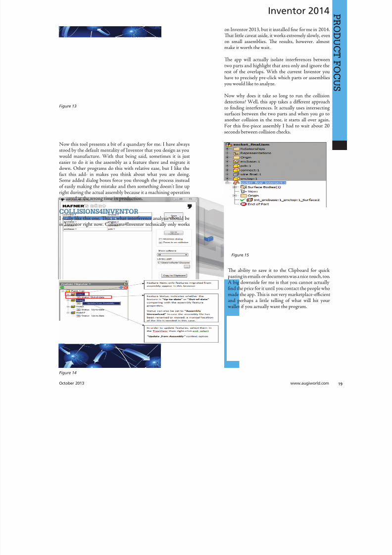
8122019 augi world 2013 10
httpslidepdfcomreaderfullaugi-world-2013-10 1952
8122019 augi world 2013 10
httpslidepdfcomreaderfullaugi-world-2013-10 2052wwwaugicom October 20
Inventor 2014
PRO
DUCT
FOCUS
TIME STAMPime Stamp is an Autodesk Inventor add-in that provides bull A low-cost simple-to-use tool that adds plot time information
to your printsbull A plot stamp that does not dirty the Inventor drawing
documentbull
A simple dockable user interface that keeps out of the way
Te ime Stamp editor lets you size position and orient thestamp relative to the adjacent sheet edges You can include datetime and current user information in the stamp Te time stamponly appears on the plot it does not alter the Inventor drawing
What I really like about this app even though it costs $500 perlicense is that you can find the price yourself and buy it It doeseverything it says it does and it provides an easy-to-use interfacewith an icon that changes based on whether the tool is on or offIf you want even more control over your plot stamping there is amore professional version offered by this company on their websitefor about $4000 a license which will allow more reporting fieldsand more control on the look and location of the stamp
SIMPLE SHEET SETTINGSSimple Sheet Settings combines the existing sheet settings withsome new tools such as changing the title block and also the abilityto make changes to all sheets in a document at once
Instead of first deleting the existing title block from a sheetexpanding the title block folder and inserting the desired titleblock then opening another window to change the sheet size andorientation just click the ldquoSettingsrdquo button located on the Sheetspanel in the Placed Views tab (right next to ldquoNew Sheetrdquo) andhave access to all those options in one location
When the Simple Sheet Settings window is loaded it gathers all the existing title block names and puts them into one drop-dowmenu o change the title block on the current sheet simply selethe desired title block from the drop-down menu and click OKTere is also the ability to change the title block sheet size ansheet orientation to all sheets at one time
Tis is a great little app that saves clicks and only costs a dollaQuite useful and no real setup involved
INTERACTIVE TUTORIALTe Create an Interactive utorial app provides instructions fcreating your own interactive Inventor tutorial Te Guide alincludes how to customize the Welcome Screen to display yointeractive tutorial and add to the ribbon
Tis one definitely falls under the ldquotoo much time on your handuser or CAD admin After reading through the guide on how create the interactive tutorials you find yourself asking the questioldquoWhy donrsquot I just save videos of the process we use in a companserver locationrdquo And that is when you uninstall this app as yohave realized that while it sounded good to you at first there abetter ways to accomplish the goal of company-specific tutoria
and process documentation
Figure 16
Figure 17
8122019 augi world 2013 10
httpslidepdfcomreaderfullaugi-world-2013-10 2152October 2013 wwwaugiworldcom
Inventor 2014
Te tools actually rely on too much externally controlled softwaresuch as Camtasia and other plug-ins and third-party apps to makeit work correctly Save your time and just use Camtasia from
echsmith to do your bidding
KEEPING UP TO DATEWith all these apps it is easy to understand how a user could getbehind on the updates to so many tools With that in mind theExchange Manager found on the ools tab in Inventor will keeptrack of that for you and offer assistance not only in updating butalso uninstalling and specialized help for each app
As a reminder with regard to third-party apps if you startexperiencing undesired effects in Inventor start turning add-ins
off one by one until you isolate which one is giving you fits Properreporting back on the app to the developers makes everyonehappier when the issue gets resolved Tus far I havenrsquot had nearas many issues as I thought I would have
ANY MANY MOREWith 80+ apps currently in the store and about 60 of them ready
for 2014 at the time of this article you should take some time andlook through what is available Tere are apps which are very nicheto the user base as well as those that have you scratching your headover why they are not already part of the core software Below aresome I would write about if I had more room in the article andora fatter PayPal walletbull BOM oolsbull EDM Expressbull Sketch Symbol Librarybull SolidWorks iProperty Importbull Quick Viewsbull 3D Pipebull Point Linkerbull Kwikools
Mark Flayler is an application engi-neer with IMAGINi echnologiesspecializing in manufacturing environ-ments He has implemented Autodeskmanufacturing products within severalindustries including the blowinjectionmolding automotive and custom ma-chinery markets When not providingtraining support and implementationhe writes the IMAGINi Manufac-turing Blog and takes an active role inthe manufacturing community Markis an AC certified instructor and isPSE and AC certified in AutoCADAutoCAD Mechanical AutoCADElectrical Autodesk Data Manage-ment and Autodesk Inventor
Figure 18
Figure 19
8122019 augi world 2013 10
httpslidepdfcomreaderfullaugi-world-2013-10 2252wwwaugicom October 20
SPECIALFEATUREAUGI Forums by Melanie Perr
The AUGI Forums are as always a busyplace Ask a question and you mightsee half a dozen varied methods andworkarounds posted in a single thread If
you have not had any questions yourself I would stilllike to encourage you to pop into the Forums and see
if there are any problems you could solve especially if you use one
of the less adopted products Tere will always be many helpinghands in the AutoCAD and Revit Forums but what about themechanical products or design visualization or structural detailingForums Peek in and see if you can share your experiences andwisdom with the community
I confess that I only scoured the English-speaking Forums forcontent for this article but please keep in mind that there areAUGI Forums available in 12 other languages so users have theoption of asking for support in their native tongue
AUTOCAD ndash SYSTEM VARIABLE
DISCUSSIONhttpbitly15M1hB9
Tis topic started out when a user couldnrsquot delete Te solution wasultimately the PICKFIRS variable but the discussion evolved tosafeguarding other variables automatically just to protect against aloss of settings in the event of a crash User Coloradomrg offeredthe safeguard shown in figure 1
Norton_cad also suggestsDIMLFAC EXPER andBLIPMODE be addedto the list
REVIT ndash
UNDERLAY
BEHAVIOR
EXPLAINEDhttpbitly15M1iFd
Mschroeder opened thediscussion with If you haveever wondered why some wallsdonrsquot show up in underlays or
show up inconsistently from floor to floor or why roofs and vieranges affect their behavior then read on
First rule of underlays Underlay view extent properties (cut rangdepth) are not user modifiable and not coupled to any othviewrsquos properties
Itrsquos also been mentioned ldquoIf objects are visible in the view ranof your current view AND in the view range of your Underlathey are automatically hidden in your underlay so there isnrsquotdouble instancerdquo
Users twiceroadsfool and dbaldacchino helped clarify the effecby posting sample models and pertinent data from the AutodeKnowledgebase and Autodesk Support Visibility View RangDetail Level and Cut Planes are all touched on in this discussioNeed clarity on how to make the most of Underlays Check inthis thread on the Forums
LISP ndash MAKING A DIALOG BOX RETAIN
ITS SELECTIONShttpbitly15JzMCc
Te LISP Forum always has such fascinating topics it is hato decide which to highlight From locking OSNAP options setting Explode options along with troubleshooting of existincode But the discussion surrounding the tutorials and metho
to retain selectioin a dialog box wvaried and lively so had to check it ou r e a v e s 0 4 4 1 3 2 1
even posted a sampdcl file when he wfinished
String Theory
8122019 augi world 2013 10
httpslidepdfcomreaderfullaugi-world-2013-10 2352October 2013 wwwaugiworldcom
AUGI Forums
AUTOCAD ELECTRICAL ndash LINES BEING
LABELED AS WIREShttpbitly1ew9p9D
Dinochrome says that one of his coworkers has reported aproblem with regular AutoCAD lines being labeled as wires
Crosswire35 advises ry checking your wire type edit dialogbox and make sure the ldquomake all lines valid wiresrdquo checkbox is unchecked
And IMCO goes on to say Using the vanilla line command inACADE will still place that line on a wire layer Change your linesto layer 0 and ACADE will not give them a wire number
AUTOCAD STRUCTURAL DETAILING ndash
TUTORIALShttpbitly17kW7cc
Te consensus is that this product is a little confusing to figure outand that most of the tutorials out there are older Most productshave a few videos floating around on Youube but this one doesnot seem to have too many yet
Jpo82 chimes in with I guess only tutorials forthis software are those found at Autodesk websiteTey are for versions 2010 and 2011 but still validhttpusaautodeskcomadskservlet12ampid=13111928 Irsquom not sure but sometimes I feel that the only new feature inASD 2013 is that itrsquos more stable than previous releases
Lucis29 goes on to say Also you might check some movieshttpwwwrobotofficecomasd but they are very old
Spenner then linked to his reporting of the Service Pack andissues it addressed hoping that it addressed some of the issuesthat came up in this discussion
NAVISWORKS ndash IMPROVE ANIMATION
EXPORT QUALITYhttpbitly1fQLoIv
Different methods are discussed from exporting individual imageframes to exporting a video (and how long) but I will leave youwith the following list from Revit For Breakfast
Here are the secrets to movies in Navisworks1 Donrsquot use materials ndash you make your render time much longer2 Use the PNG export option 15fps3 Make your video export twice as long as you need Ten speed it
up for a faux 30fps Tis is faster4 Look up the Navisworks blog by Lee Mullin and Paul Walker
about gooch and phong Tere is your faux render setting5 If you have NW 2012 you wonrsquot have gooch or phong but you
will have better export options 2013 has gooch and Phong butfewer export options
6 Te flickering occurs when multiple shapes overlap If you care
delete them in your export model Sometimes flickering occurs
in the generation of your frames on the PNG export You mayhave a frame that is ldquooffrdquo
7 Set your anti-aliasing to 4x or better on the png export8 Check out my old post httpforumsaugicomshowthread
php132209-Animation-Resolutionampp=1138298ampviewfull=1post1138298
CAD MANAGEMENT ndash NETWORK DRIVE
CHANGED BY IT WITHOUT WARNINGhttpbitly18J4k9c
Blackbox advises edinsmore595165 straight off to utilize theReference Manager program that comes with AutoCAD inorder to reconnect all of the external reference paths that werebroken when the I department upgraded their archaic serversHe further points out that moving from hard pathing to relativepathing would make things easier in the future
Feargt offers another twist Another option which would workon a need only basis when you open the specific drawing Change
XREF and Image paths in drawing to Network path throughscript on a need only basis Basically this will only change pathsPlace this line in a acaddoclsp file(command ldquoscriptrdquo ldquoyourserver and pathXREFREDIRECscrrdquo)and the following in a script fileREDIRB enter name of path to be replacedP enter new path
Tere was also a debate in this thread about obstacles and benefitsof user-managed and I-managed drive mapping
Melanie Perry is a Facilites-Manage-ment Coordinator and echnical Edi-tor in St Louis MO She is the AUGISalary Survey Manager and is curring-ly serving as an Officer on the Board ofDirectors Melanie can be reached atmistressofthedorknessgmailcomor found on witter asMistresDorkness
OTHER HOT TOPICSHave you found a Forum solution so mind-bogglinglyuseful that you leapt out of your chair with a whoopingcheer (or were at least tempted to) Please let me know Asingle person cannot read every post in our bustling AUGIForums so if you would like to see a thread highlighted ina future edition of String Teory feel free to let me knowSend me Wanderer a PM in the Forums or send an emailto MelaniePerryaugicom
See you on the Forums
8122019 augi world 2013 10
httpslidepdfcomreaderfullaugi-world-2013-10 2452wwwaugicom October 20
Revit Architecture 2014
PRO
DUCT
FOCUS
by Martijn de Rie
Myth Buster
Revit amp IFCPart 3
Irsquove given a lot of thought as to how this trilogyof articles should end At first I thought Irsquoduse the Coordination View 20 EXPRESS-GWallPaper for IFC2x3 (httpwwwmdr-
adviesnlwp-contentuploadsCoordinationView_V2-0_WallPaper_IFC2X3_Version-1pdf ) as a stepping stoneto give an ldquoIFC for Dummiesrdquo type of solution But that turnedout to be quite lengthy and rather boring But the link is includedabove for obvious reasonsmdashitrsquos useful
So I went back a little and asked myself ldquoWhy IFCrdquo And with thatquestion the inevitable follow-up immediately appeared ldquoWhynot IFCrdquo I realized that in the previous articles I failed to explainwhy in my humble opinion we should care about this somewhatcrooked badly implemented severe headache-inducing formatTerefore instead of explaining the fundamental technicalities ofIFC that can be explored in other places this final installment willexplore the Why versus Why Not IFC discussion and begin withthe latter
WHY NOT IFCWhen everybody uses Autodeskreg RevitregWell in this case itrsquos a no-brainer Share your Revit files Period
Loss of dataTis is an easier way to share data instead of hacking your wthrough IFC and praying your stuff doesnrsquot get lost in the proce
Even when you manage to export your geometry through IFtherersquos always loss of data
Loss of intelligence during importEven if you only need to send over geometry not data importithat into Revit makes it utterly useless All constraints are locomponent parametrics are gone and so on
Availability of bidirectional linksWhen not everyone uses Revit on a given project (which is quoften when yoursquore not located in the US) why not simply ua bidirectional linking between proprietary software standardTis can be easier and better to control
8122019 augi world 2013 10
httpslidepdfcomreaderfullaugi-world-2013-10 2552October 2013 wwwaugiworldcom
Revit Architecture 2014
WHY IFCWhich may be asked as why would you want to use IFC Or moreaccurately why would you want that option available
Consider what Sir Arthur Conan Doyle wrote ldquoOnce you eliminatethe impossible whatever remains no matter how improbablemust be the truthrdquo
Letrsquos put that to the test shall we
When everybody uses RevitOkay simple math Autodesk has around 7000 employees Teworld has about 72 billion people What are the chances someonenot working for Autodesk has a brilliant idea and creates thesoftware you need tomorrow Tere will always be better solutionsTey might not be viable for you overall but therersquos no reason toshut down access to them Revit is a wonderful generic tool forwhich I see a brilliant future with all kinds of additions for specificniche-markets like AutoCAD has
What about today DDS is MEP-engineering software that cando energy calculations (not simulations) inside your modelRhino lets you model things on the fly that could (arguably)take ages in Revitmdashif you ever get them done ekla lays wasteto the Revit structural rebar functionality any day of the weekwithout breaking a sweat Solibri is a wonderful solution for clashdetection and most importantly rule-based model checking andreportingmdashsomething Revit (or Navisworks) doesnrsquot do
Should I go on
Only problem for all this magnificent software Itrsquos either based onthe IFC format or requires model exchange through IFC
Te fact of the matter is there will always be better softwareAny one may be the software for you but that doesnrsquot mean yourpartners associates etc need to have the choice to use it forcedupon them
Loss of dataOn July 1 2013 there was an extra release for Autodesk softwareTe Sourceforge Open Source IFC Exporter released a new versionthat incorporated the option to map custom Revit parameters(shared or non-shared family or project even calculated values) totheir IFC counterparts
On September 28 2013 I had the honor of showing the secondstep in a complete and controllable data export from Revit
During my RC Europe class I showed the new option to create acustom IFC Property Set and map any given Revit parameter intoIFC fully customizable
IFC does not automatically lead to loss of data Tat idea is simplynot true Incomplete implementation in Revit does lead to loss ofdata As of now you are able to put any piece of data into an IFCeven calculated values And we didnrsquot change the IFC format We
just improved implementation in Revit
Loss of intelligence during importldquoJust because something hasnrsquot happened yet doesnrsquot meanitrsquos impossiblerdquo
I donrsquot know who originally had this insight and I doubt it to bethe movie line I remember but it is true
In the same RC Europe class I showed a native Revit familybeing exported to IFC altered and re-importedmdashwhile keepingall parametric constraints and even adjusting to the alterationsmade directly in the IFC file It is possible but not with thecurrent importer
Availability of bidirectional linksIrsquove been using Revit for almost 10 years now For 4-5 years I didnrsquotknow about IFC at all Before a year ago this was my strongestargument against IFC Why would you need a generic ldquolanguagerdquowith all its limitations (of which there are) weaker implementationand use of parametric capabilities (because it has) and lag-times indevelopment (by nature)
IFC will never be able to do what native software does simplybecause itrsquos responsive in nature Development budgets are afraction of what Autodesk rimble or Nemetschek get to spendon their software
So why not keep it simple and use a bidirectional link Revit has itwith a lot of other Autodesk software and third-party applications
But how long have we waited for them And are they even trulybidirectional Do they exactly do what you want them to do In myhumble opinion the answer to these questions is not very inspiringEven bidirectional links tend to have major limitations and severe
constraints in flexibility And most important Te link itself isalso propriety software No way of adjusting it to your needs
WHAT IF MORE PEOPLE STOPPED
TALKING ABOUT IT AND JUST GOT
INVOLVEDTe improbableFirst off itrsquos a matter of simple logic As Sir Arthur suggested ifwe can successfully check off all likely options to NO want touse IFC doesnrsquot that mean the improbable is true Tat IFC is infact a valuable tool in our toolkit and we should be able to use it
when necessary
Mind you Irsquom not saying you should use IFC If yoursquore on a Revit-only project it would be insane Just send and receive RVs Tefact is this will only be viable for limited parts of the buildinglifecycle If yoursquore lucky the entire design team is on Revit Butmanufacturers have other software facility managers too
As for the design team what if the best structural engineer is not[on Revit] or the MEP guy that has loads of experience in similarprojects Would you settle for second-best just because someoneuses the same brand of tools you do I wouldnrsquot
8122019 augi world 2013 10
httpslidepdfcomreaderfullaugi-world-2013-10 2652wwwaugicom October 20
PRO
DUCT
FOCUS
Revit Architecture 2013
Open AccessWhich brings us to the biggest advantage of IFC (or any open
format) itrsquos open Which means itrsquos adjustable to your needs Nowdonrsquot go ldquothatrsquos too difficult expensiverdquo Tatrsquos bullocks
Te first external enhancement to the Open Source Exporter wascreated by om Pesman a self-employed API specialist
Parametric IFCImplemented by Jon Mirtschin also self-employed IFCparametrics is available Agreed Jon is a well-known IFC guru butstill the point holds
Custom property sets and parametersWim as owner of a small MEP engineering firm hasadded functionalities toward this end and hersquos not even a trueAPI specialist
All these developments were done for free by altruistic volunteerefforts as part of the creation of the Dutch Revit Standards Andof course with the invaluable help of the Autodesk Open SourceIFC Exporter team Angel Velez in particular
But what if these guys actually got paid What if this projectwasnrsquot a Saturday night side-job What if more people stoppedtalking about it and just got involvedmdasheither by themselves or byleveraging experts to get what is needed Te entire IFC format is
Open Source the source code is out there which basically meansyou can do whatever you want and create whatever you needmdasheven on a project-by-project basis
BIM ITrsquoS THE ldquoIrdquo THAT MATTERSIn my humble opinion the entire debate on BIM is focusing on thewrong part of the acronym I donrsquot care if ldquoBuildingrdquo is a noun ora verb Nor do I care whether itrsquos ldquoModelrdquo or ldquoModelingrdquo nor am Icommenting on whether one should say ldquoBIM Modelrdquo
Itrsquos the ldquoIrdquo that matters If wersquore collaborating the Informationis most all I care about I just want your datamdashin the leanest
smartest and most effective way possible
A Revit model will do conversely a lot of times A Revit model w
give me heaps of data I donrsquot want geometry I donrsquot care about ana file format I canrsquot use Now we can all keep on being really anabout it or we can simply use the tools available to us one of thebeing IFC
A FINAL NOTEAs stated at the beginning of the article I really enjoyed writinthis series and for now this is the last of the series But if yoursquointerested in more tips and tricks on IFC let me know I might able to persuade the guys at AUGI to let me write about it againLord knows there is still a lot to talk about regarding IFC
Martijn de Riet is a self-employedBIM Consultant from the Nether-lands working with Revit since version51 Martijn has a bachelor degree inBuilding Science After his studieshe started his own engineering firmworking for contractors architects and
private clients Starting in 2007 hiscompany transformed into a full-timeBIM consultancy service At the mo-ment Martijnrsquos clients vary from mid-sized architectural firms to the largest
dutch General Contracter and MEPEngineering firms with a focus onspecific corporate solutions design andimplementations of Revit and BIMworkflows Martijn is a member ofthe Dutch Revit User Group and cur-rently working on creating a Masteremplate and Component LibraryHe provides lectures for companiestechnical universities seminars etc ona regular basis
Itrsquos the ldquoIrdquo that matters If wersquore collaborating the Information is most all I care about I justwant your datamdashin the leanest smartest and
most effective way possible
8122019 augi world 2013 10
httpslidepdfcomreaderfullaugi-world-2013-10 2752
wwwxicomputercom
8122019 augi world 2013 10
httpslidepdfcomreaderfullaugi-world-2013-10 2852wwwaugicom October 20
3ds Max 2014
PRO
DUCT
FOCUS
by Chris Murra
SUMMARY WHATrsquoS
CUSTOMIZABLE IN MAX
(HIGH LEVEL)When it comes to the customizability of Autodesk 3ds Maxregitrsquos no secret that it can morph itself into whatever you want theprogram to become
Whether yoursquore a modeler animator lighter rigger generalist ortechnical artist 3ds Max can become your own personalized toolbox that is an extension of your own hand in your daily workYou can now combine different command types (such as creatingobjects and object modifiers) into a single menu reducing themouse travel and improving efficiency
In this article wersquore going to take a closer look at one specificaspect of customization with 3ds Max the new enhanced UI Aspart of this article besides taking a deep dive into the operationof this feature I will also be showing how I created the ldquoMographrdquo
tools UI that includes custom buttons and icons At the end this article I will also provide a link to this UI so you can use customize it yourself or share it with others
ENHANCED UI SUMMARYWhat is the Enhanced UI
Te Enhanced UI is a new graphical user interface system thdoes two main things
1) It provides a refreshed 3ds Max user interface with updattool categories and new clusters of pre-existing tools in groupinthat are more akin to their intended purpose as opposed to somtechnical requirement for menu placement
2) It provides a way to allow you the end user to customize thmenu system in almost any way you choose Te drop-down menare ldquotear-ablerdquo (not to be confused with ldquoterriblerdquohellip but I digresand the resulting configurations are savable either by scene or
3ds MaxEssentialsCustomizing
the UI
8122019 augi world 2013 10
httpslidepdfcomreaderfullaugi-world-2013-10 2952October 2013 wwwaugiworldcom
3ds Max 2014
a preset Tey are also distributable and deployable so they can beshared with others
Where is the Enhanced UITe Enhanced UI can be found in the upper left hand corner of themain UI at the very top of the screen Tere is a drop-down menuthat says ldquoWorkspace Defaultrdquo Tis default is the same baselineUI that ships with all 3ds Max installs (Figure 1)
Within the drop-down you can find the ldquoDefault with EnhancedMenusrdquo Tis is the alternative default menu system that youcan use on its own or use as a starting point to create your owncustomized menus
BASIC DEFAULT CUSTOMIZATIONEnhanced UI Customization BasicsNow that wersquove enabled the Enhanced UI how can we change it
SOP Before you begin mucking around with the UI Itrsquos importantto understand what I call the ldquosave-logicrdquo as it pertains to custom UIs
Te UI Save LogicIf you plan on saving this UI for future use there is a specificmethod you must follow to properly save the UI you want and notwreck the default Enhanced UI
Te Save Logic is as follows Itrsquos simple but important
Step 1 urn on Enhanced Default UI (Figure 3)
Step 2 Click ldquoSave as New Workspacerdquo FIRS At this point youwill be prompted for a new name (Figure 4)
Step 3 Edit and change the UI at will
NOE All future edits are ldquoautomatically rememberedrdquo as you go (Iintentionally did not use the word ldquosaverdquo)
Step 4 Te ldquosave as default staterdquo button is important When wehave completed the customization process we then choose thisbutton to ldquolockrdquo in the changes Tis is different than Saving a UIwith a custom name
HO IP ldquoBut this methodology seems backwardrdquo
I can see how yoursquod say that but remember that any changes you make
to any enhanced UI are automatically ldquorememberedrdquo If you create acustom UI then while working you make some temporary changeswhen doing something specific those little changes are automaticallyremembered If you want to return to the default state [of yourcustomized UI] you select ldquoReset to default staterdquo Tis does NObring back the default Max UI rather it brings back the customizedUI you created in ldquolockedrdquo in Step 4
Okay now that you have the save logic down letrsquos begin customizing
1) If you havenrsquot done so already turn on the Default Enhanced UI
2) Go to ldquoManage workspacesrdquo from the drop-down and in the
Figure 1 Workspaces are in the Workspace drop-down menu
Figure 2 Default UI (left) and the Default Enhanced UI (right)
Figure 4 Saving the New UI Workspace
Figure 3 Turning on the Enhanced Default UI
8122019 augi world 2013 10
httpslidepdfcomreaderfullaugi-world-2013-10 3052wwwaugicom October 20
3ds Max 2014
PRO
DUCT
FOCUS
Manage workspaces dialog choose ldquoSave as new Workspacerdquo Giveit a specific name
3) Begin making your desired changes
Since a custom UI is specific to any one individual letrsquos take a lookat what types of customizations can be made
Simple ChangesOne of the simplest things to do is peel off any commandgroup (see Figure 5) Just click the group title bar and drag Tecommand group becomes a floating dialog box Now just becauseyoursquove peeled it off does not mean that yoursquove removed it fromthe drop-down menu Te ldquooriginalrdquo command group remains inthe drop-down You can just close the floating dialog when yoursquoredone with it
Probably the simplest thing you can do is reorganize the menusIn each drop-down menu appears a group of commands You maynotice that some command groups are icons and some are words(Figure 6) o change the appearance of the commands there is asmall icon in the upper right corner of each group of commands(Figure 7)
Te next change is alreally simple Is tcommand group op(expanded) or clos(rolled up) Just clion the plus or minsign in the upper le
corner to set this stafor the next time yolaunch 3ds Max (Figu8) Remember thesettings are saved as yogo so whether it is opor closed is your choicbut the state the menis in when you cloMax is the one that remembered the netime Max opens
What about Saving tDefault state More othis later
Once you have floating menu yocan combine differecommand groups dragging any othcommand group to aother floating dial
that yoursquove created Tis makes for easy creation of custom dialo
based on specific tasks Figure 9 shows a command group fcharacter animationFigure 5 A floating menu that has been torn off the drop-downmenu
Figure 6 The different display states of the menus
Figure 7 Changing menu layouts
Figure 8 Rollouts
8122019 augi world 2013 10
httpslidepdfcomreaderfullaugi-world-2013-10 3152October 2013 wwwaugiworldcom
3ds Max 2014
ADVANCED CUSTOMIZATION
What about completely custom interfaces Herersquos how we do thatwith the Enhanced UI menu system
Te following is the high-level overview of the process Wersquoll thenunpack each step in more detail
If you havenrsquot read the section on Basic default customizationplease do so before continuing Before starting this phase ofcreating your new UI you should have saved your new UI stateTat process is explained in the previous section
1) Create a main drop-down menu (like ldquoMy oolsrdquo)
2) Create a tools category menu into which you will place yourtools (a submenu such as ldquoModeling oolsrdquo or ldquoAnimation oolsrdquo)Drop-downs can have more than one subcategory
3) Add commands to various submenus
4) Clean up the UI by creating custom names adding separatorsor creating custom icons
First letrsquos create a new menu for the menu bar Tis is done easilyfrom the CustomizegtCustomize [Rollout]gtCustomize UserInterface dialog box
Steps for Creating a Drop-Down Menu1) Create a New Menu and give it a name (see Figure 10)
2) Locate your new menu in the Menus window It will be listedalphabetically (Figure 11)
Figure 9 Multiple command groups in one menu
Figure 10 ndash Creating a new drop down menu
Figure 11 Location of new menu
8122019 augi world 2013 10
httpslidepdfcomreaderfullaugi-world-2013-10 3252wwwaugicom October 20
3ds Max 2014
PRO
DUCT
FOCUS
3) Drag your newly created menu category over to the column onthe right Tis will add your new drop-down menu to the interfaceimmediately and you can begin populating it with menu items (seeFigure 12)
UI DESIGN IP Te actual menu name and display name can bedifferent I used a custom menu name behind the scenes so I couldeasily differentiate my menus from the ones created by default or other
tool companies After you create a menu and add it to the right column you can right-click on it and change its display name (see Figure 13)
Next letrsquos create a command group1) Just like in Step 1 from the previous section create a new men
2) Tis time before you drag it to the right column click thplus sign next to your drop-down menu item to expand it Tedrag the new item to the right column dropping it ldquounderrdquo thmenu name
3) Drag any commands from the Commands window on the leto the submenu on the right (see Figure 15)
Herersquos an example from my Mograph ools workspace thshows how a completed menu looks once it is created (Figu16) In the following figure you see both the menu as it appeain the Customize UI dialog and the actual menu (which has bepeeled off)
Notice that some of the commands on the menu are greyed ouTatrsquos because this new menu combines both ldquoObject creatcommands and ldquoObject Modify Commandsrdquo in one menTey will remain grey until you create an object on which thwill be used
Figure 12 Adding the new menu to the UI
Figure 14 Creating a command group
Figure 15 Dragging commands onto the menu
Figure 13 Custom menu names
8122019 augi world 2013 10
httpslidepdfcomreaderfullaugi-world-2013-10 3352October 2013 wwwaugiworldcom
3ds Max 2014
Adding SeparatorsSeparating commands is easy and is recommended to help you oryour intended user make sense of the how the tools are arranged inthe menu Creating a separator is as easy as dragging one over theright column just like a menu or command
HO IP ldquoWhy do I need to create another menu Why canrsquot I addtools right to my menurdquo
Te main reason is that adding a submenu gives you the ability to tearoff the submenu If it werenrsquot in a submenu it wouldnrsquot be tear-ableSo itrsquos really a ldquobest practicesrdquo kind of thing But even if you try to notadd the submenu it will happen automatically Itrsquos important to do it
explicitly so you are aware of what submenus are in the menu and that you are the one in control of what command is going where
CUSTOM ICONSNo custom UI is complete without a custom set of iconsAdditionally not all commands in 3ds Max have their own iconyet But itrsquos important to realize that regardless of how you set up
your UI yoursquore still working within the framework of an existingapplication and there are boundaries to what you can edit andcreate Icons have specific requirements both in their creation(size) location and file name that must be adhered to in order forthem to work properly
SizeformatTe size of icon is pretty simple It must be 32x32 pixels andPNG format
LocationTe location is very specific New icons must be added to thislocation
CProgram FilesAutodesk3ds Max 2014UI_lnResourcesDarkIconsMain
Te new icons I created for the Mograph UI are shown inFigure 17)
Icon File NameIf yoursquore still with me at this point we are now getting into thenether regions of customizing a UI Tis is where things get a littletricky but itrsquos really not too bad File names are specific and aregenerated by the application (3ds Max)
So letrsquos begin First identify the command for which you want aniconmdashusually itrsquos one that doesnrsquot already have an icon But if itdoes and yoursquore changing it MAKE A BACK UP of the originalicon PNG file Tis is because as previously stated you donrsquot havecontrol over the file name Tat means if yoursquore creating your ownicon you need to overwrite the existing one and use its name foryour new icon So back up any original icons
Figure 16 The completed menu
Figure 17 ndash The created icons
8122019 augi world 2013 10
httpslidepdfcomreaderfullaugi-world-2013-10 3452wwwaugicom October 20
3ds Max 2014
PRO
DUCT
FOCUS
It really doesnrsquot matter whether you make the icon first or not ofind the name you need to use you need to navigate as follows
NOE Yoursquore about to edit the ribbon Tere is no need to save thesechanges as we are merely extracting information from it But if yoursquoredoing a lot of custom icon work you may want to save this change to theribbon so you can come back and continue your work in later sessionswithout have to recreate this every time just to get the proper file nameSaving this ribbon is not related to saving your default state of yourUI When yoursquore done creating all your UI icons you can just delete
whatever changes you make to the ribbon
1) Open the ldquoCustomize Ribbonrdquo dialog box
2) Create a new ldquotabrdquo by dragging it onto the ldquoExisting Ucolumn in the middle (see Figure 18)
3) Using the same drag method add a new ldquopanelrdquo to ttemp tab (Figure 19)
4) Now you can get the information you need Find tcommand for which you are creating an icon and dragto the panel
5) Locate the ldquoinfordquo portion of the ldquoPreview Windocolumn At the bottom of the column is the file namneeded to have the icon used properly by the applicati(Figure 20)
CONCLUSIONSo now you know how to create a custom UI scheme f3ds Max 2014 and up By using the Enhanced UI me
system itrsquos really easy to generate a multitude of workspathat allow Max to work the way you want to work
Te example used in this article was the ldquoMographrdquo UI thI created for NAB 2013 If you would like to downloand install it you can get it from my ldquoPinning the Stacblog on the Area herehttpareaautodeskcomblogschrismurray
Enjoy
Chris Murray works for Autodesk
Media amp Entertainment He istrained as an animator (3D variety)but considers himself a creative tech-nologist His daily role is a technicalldquoevangelistrdquo for Autodesk creating marketing deliverables for 3ds Max Heis the author of Mastering 3D StudioMax He has a Masters in Fine Arts(MFA) in Computer Animation fromMiami International University of Artand Design Follow him on witterchrismmurray
Figure 18 Creating a tab on the ribbon
Figure 19 Adding a panel to the tab
Figure 20 Finding the required file name
8122019 augi world 2013 10
httpslidepdfcomreaderfullaugi-world-2013-10 3552
AUGIMembersReach Higherwith ExpandedBenefitsAUGI is introducing three new Membership levelsthat will bring you more benefits than ever beforeEach level will bring you more content and expertiseto share with fellow members plus provide anexpanded more interactive website publicationaccess and much more
MEMBERMEMBER MEMBER
Basic members haveaccess tobull Forums
bullHotNews (last 12 months)
bull AUGIWorld (last 12 months)
DUES Free
Premier members haveaccess tobull Forums
bullHotNews (last 24 months)
bull AUGIWorld (last 24 months)
DUES $25
Professional members haveaccess tobull Forums
bullHotNews (full access)
bull AUGIWorld (full access and in print)
bull ADN 2013 Standard Membership Offer
DUES $100
Are you ready to upgrade yourself and your membership
Access additional benefits and upgrade at wwwaugicom
8122019 augi world 2013 10
httpslidepdfcomreaderfullaugi-world-2013-10 3652wwwaugicom October 20
AutoCAD MEP 2013
PRO
DUCT
FOCUS
by Vladimir Triantafillid
BIM IsWhatrsquos
Driving theIndustry
For the past decade many would arguethat building information modeling(BIM) has metastasized aggressivelythroughout the AEC industry but what
does BIM really mean More importantly whatdoes it do for us and for our industry Ask someone who hasbeen in this industry for more than 25 years or those nearingretirement and yoursquoll find that less than half see its value muchless care to make the effort with its implementation hesequestions mean something different for those who have beenin the industry the past 10-15 years Recent college graduates
however with their tech-savvy capacity and high expectationare eager to implement anything that resembles cutting-edgflashy technology ypical ly they are the ones most receptivenot adamant about putting their talents to use through BIM
I recently gave a BIM presentation with an emphasis on mchanical systems to the summer interns and new hires our companymdashall were non-BIM users except for onemdashbmy presentation did little justice to BIM Half of my audence had found a cure for their insomnia when they realizthis wasnrsquot the latest edition of ldquoCall of Dutyrdquo hat was n
8122019 augi world 2013 10
httpslidepdfcomreaderfullaugi-world-2013-10 3752October 2013 wwwaugiworldcom
AutoCAD MEP 2013
reflection on BIM by any measure Simply put I fell shortof connecting with a potentially captive audience eager toknow what really makes BIM intriguing or how it wouldgive them an edge in the industry I didnrsquot think to look pastpresenting the facts of its processes and benefits o simplyhave stated that proficiency in any of its many facets willpromote a lucrative career would give those still awake theimpetus to jump ship In hindsight the first step I shouldhave taken to begin this presentation was to ask what theywanted to get out of BIM
If you think itrsquos hard conveying the value and splendor ofBIM to receptive and impressionable young minds try toconvince the weathered veterans dead-set in their ldquooldtricksrdquo For every experienced veteran who has converted toBIM there are two ldquoold dogsrdquo that canrsquot shake ldquothe good olrsquodays when we used vellum and light tablesrdquo Guess whatmdashanincreasing amount of naysayers are starting to come aroundincluding those who say theyrsquove been burned by BIM in thepast hey are seeing the simple solutions BIM presents and
how these solutions translate into cost savings More andmore of those who had formerly questioned BIMrsquos utility areconvinced when installation efficiencies are not only real-ized but quantified
Another factor in the evolution of BIM is its tendency toexpand faster than the pace of its general population of us-ers hose of us proud to be catching up to what we think iscutting edge quickly realize it was just another false sense ofaccomplishment as BIMrsquos web continues to grow exponen-tially he solution is rather simple Focus on what you canhandle and always have the presence of mind and sense ofcaution to avoid being overwhelmed by the wake of BIMrsquos
progress herersquos plenty of money to be made and countlessfacets to explore as long we have the following mentality Welive in the information age and those wi lling to share knowl-edge will reap the rewards of communal synergy
On the opposite end of the spectrum you might find ourindustryrsquos opportunists In a hurried frenzy to claim theirspot in the intellectual property queue these opportunistsget carried away with pioneering what they assume is the lat-est improvements to BIM Instead of stopping to absorb anddevelop the benefits of 4D 5D 6D and so on the pioneersare spreading these ldquoDsrdquo thin with abandon further expand-
ing the gap between quality and quantity None of this i s tosay that wersquore heading in the wrong direction On the con-trary letrsquos call it more of a positive economic problemmdashthedemand for BIM expertise and development outweighs thesupply of available users
Fortunately as collegiate curricula catch on to this industrytrend the point of equilibrium will soon follow For as longas I can remember respective companiesrsquo 2D CAD depart-ments have been a significant source as the breeding groundfor potential BIM users While this route hasnrsquot changedregarding the career path of a draftsperson the source poolhas expanded to include architects engineers and construc-
tion managers just to name a few Itrsquos even hard not to noticeits stark demand when BIM and Revit courses are being in-creasingly offered at local community colleges I knew thenthat you didnrsquot necessarily need an undergraduate degreeback when I got my foot in the door of this industry hisprobably wonrsquot hold true in the coming years Still the privi-leged few who are already a part of this industry subset canrely on their experience in this fast-paced market to con-tinue to propel their careers forward ever faster All thesefew need to do is grab onto a small piece of BIMrsquos wing andhang on tight for the ride he fresh-out-of-college e ntrantsmight have a harder time grabbing onto this wing thatrsquos al-ready in motion
o those who are only vaguely famili ar with BIM it is typi-cally perceived as the equivalent of a 3D role-playing videogame In this case itrsquos not difficult to capture a ldquosnapshotrdquoimage of a 3D model shadows cast across random metal ob-
jects taking up space in an orderly fashion between ceil ingspaces and walls What is difficult is conveying the abun-dance of value behind the pretty picture to a client whorsquosonly interested in the pretty picture Who isnrsquot familiar withthe adage ldquoa picture is worth a thousand wordsrdquo Why notchange that saying to ldquoa BIM model is worth five thousandhyperlinksrdquo Now wersquore talking lifec ycles and facilities man-
More and moreof those who had
formerly questioned
BIMrsquos utilityare convinced
when installationefficiencies are notonly realized but
quantified
8122019 augi world 2013 10
httpslidepdfcomreaderfullaugi-world-2013-10 3852wwwaugicom October 20
AutoCAD MEP 2013
PRO
DUCT
FOCUS
agement his supposed video game has suddenly becomean encyclopedia of usable information But wait itrsquos not juststatic information thatrsquos stuck on a DVD on a shelf i n someownerrsquos random storage closet It has now become a livingdynamic source of real-time data Maintenance technicianswill know exactly where to go when the active 3D modelloaded on their laptop highlights a hot water pump needingservice while concurrently bringing up the cut sheets andoperation and maintenance manuals specific to that pumpor system Better still the source of information has shiftedfrom multiple stacks of large drawing sets collecting dust toseveral hundred gigabytes on a hard drive Yes Mrs Clientyour 3D BIM model will be usable for the next 20+ years
Even though you might not necessarily think about i t someof you probably realize that BIM has become the ldquomiddle-manrdquo for so many key components in the construction cyclewell beyond its intermediary role between design and con-struction phases You want to do some significant tenantimprovement in an existing building Laser-scan the exist-ing conditions hatrsquos BIM Is the general contractor rackingtheir brain trying to f igure out where to station the crane forthe project or pave the pathways for delivery trucks Nowtheyrsquore looking to BIM to answer these questions and opti-mize their decisions o take it a step further at which endof the building do we want to load thousands and thousands
of pounds of sheet metal and pipe And then which tradesshould be installing their systems first in any given area ofthe building hatrsquos right wersquore deriving sequencing andtimelines from the BIM model to e stablish the best routes totake while addressing any constructability issues BIM hasbecome the consultant that wears most of the hats Itrsquos ourone-stop shop
I know that Irsquove personified BIM as if itrsquos the brains behindall of its success Letrsquos take a moment to focus instead on itscollaborators or the sum of its integral parts to show thatin reality we are Dr Frankenstein and BIM is our monster
Except in our ca se wersquore beginning to ta me our monster anthose who were previously frightened by it are starting to sthat it indeed is no monster In fact while evolving to domdashand becomemdashgreater things BIM is transforming into aindustry hero he point of convergence is approaching bcause wersquore saving money time and even trees Soon enougBIM will be the industry standard even on the smaller proects Letrsquos keep the pedal to the meta l
You want to know the best news Most of us havenrsquot evebegun to scratch the surface of BIM but wersquore in strategpositions to reap the rewards aking the possibility of ivast potential into account isnrsquot it reassuring knowing th
in these tough economic times wersquore engaged in an industthat has a shortage of well-qualified BIM experts Our eposure alone sets us up for success Now ask yourselves thquestion Is BIM driving our industry or is it the BIM use
Vladimir riantafillidis works for aleading mechanical contractor in theSan Francisco Bay Area with morethan 10 years of experience in the in-dustry Although he has a bachelorrsquosdegree in biology his unique careerchoices have firmly rooted him in a
substantial BIM role awarding himthe opportunity of progressing along-side the relentless evolution of BIMOutside of his career hersquos always opento new adventures whether trying anew cuisine exotic travels or extremesports Te latter adventures have re-cently subsided as the balance of lifehas shifted his focus on spending timewith his growing family
You want to know the best news Most of us havenrsquot
even begun to scratch the surface of BIM but wersquore
in strategic positions to reap the rewards
8122019 augi world 2013 10
httpslidepdfcomreaderfullaugi-world-2013-10 3952
8122019 augi world 2013 10
httpslidepdfcomreaderfullaugi-world-2013-10 4052wwwaugicom October 20
Revit Structure 2014
PRO
DUCT
FOCUS
Streamlining
Sheet Listswith a Custom
Application
In this article we take a brief look a simpleadd-in for Autodeskreg Revitreg named X-Sheetswhich provides tools for incorporating sheetsfrom an AutoCADreg sheet set in a Revit sheet
list ypically this is handled by manually addingplaceholder sheets to the Revit sheet list Tis can be problematicbecause the sheet list becomes disconnected from the sourceand must be updated manually With X-Sheets sheet set datais exported directly from AutoCAD linked to a Revit project
and included in the sheet list by automatically addingupdatinplaceholder sheets For this example all structural scheduleplans elevations and section sheets are in Revit Structure Adetail sheets will be pulled from an external AutoCAD sheet set
X-SHEETS RIBBON PANEL Te first command on our ribbon panel is Discipline Tcommand is used to establish the Revit project parameter twhich the AutoCAD sheet subsets will be mapped For th
by Jonathan Albe
Figure 1 Revit X-Sheets ribbon panel
8122019 augi world 2013 10
httpslidepdfcomreaderfullaugi-world-2013-10 4152October 2013 wwwaugiworldcom
Revit Structure 2014
example we have created a project parameter named My DisciplineParameter Each Revit Structural sheet has been assigned a valueof SRUCURALmdashthe same as the subset name for theAutoCAD detail sheets Te sheet list is grouped and sorted bythis parameter
Te next command on the ribbon panel is Links Tis command isused to establish a link between the Revit project and XML file(s)
containing sheet information exported from AutoCAD You cancreate as many links as needed and use relative paths if required
Te next two commands Sheets and Update do the work ofaddingupdating placeholder sheets to the sheet list While theSheets command allows you to select individual sheets from linksto include in the sheet list the Update command includes all sheetsfrom all links
EXPORT SHEETS FROM AUTOCADFigure 3 shows the AutoCAD X-Sheets ribbon panel and asample sheet set containing structural detail sheets Notice thedetail sheets are grouped under a subset named SRUCURALTis subset name can be exported with each sheet and mapped to
the My Discipline Parameter in Revit Figure 3 shows the ExportSheets dialog with an option to include subset information and theability to exclude individual sheets Selecting the Export buttonprompts us with a dialog to save an XML file to be linked into ourRevit project
Figure 2 Discipline command dialog
Figure 3 AutoCAD X-Sheets ribbon panel and sample sheet set
Figure 4 Export sheets dialog
Figure 5 Export complete
8122019 augi world 2013 10
httpslidepdfcomreaderfullaugi-world-2013-10 4252wwwaugicom October 20
Revit Structure 2014
PRO
DUCT
FOCUS
ESTABLISH LINK TO XML FILE IN REVIT
PROJECTFigure 6 shows the Manage Links dialog A link has been added tothe XML file we generated when exporting sheets from AutoCADNotice there is an option to make the link path relative to our
Revit Project location
IMPORT SHEETS FROM XML LINKFigure 7 shows the Revit Structure sheet list before any sheetshave been imported from AutoCAD After selecting the Sheetscommand we are prompted with a Manage Sheets dialog
For this example we have selected all sheets from the XML linto include in our sheet list After confirming the dialog neplaceholder sheets are immediately added to the sheet list angrouped according to the SubsetDiscipline mapping Te neplaceholder sheets are identified behind the scenes as being relatto the X-Sheets XML link for later updating
Figure 6 Manage Links dialog
Figure 9 Sheet list after import
Figure 7 Sheet list before import
Figure 8 Manage Sheets dialog
The X-Sheets
add-in is a great tool
for incorporating
AutoCAD sheets into
a Revit sheet list
8122019 augi world 2013 10
httpslidepdfcomreaderfullaugi-world-2013-10 4352October 2013 wwwaugiworldcom
Revit Structure 2014
UPDATE SHEETSFigure 10 shows the Export Sheets dialog in AutoCAD afterdetail sheets have been renumbered to include ldquo-Ardquo When changesare made to AutoCAD sheets the original export steps must befollowed to replace the XML file linked to our Revit project Oncethe XML has been replaced simply run the Update command inRevit to update the sheet list
SUMMARYTe X-Sheets add-in is a great tool for incorporating AutoCADsheets into a Revit sheet list Te add-in saves time by automatically
adding placeholder sheets eliminates room for error in manualtranslation and helps to keep your sheet list up to date withminimal effort
Jonathan Albert is co-founder of BIM- pulse echnologies LLC amp SeniorApplications Developer at LindemanBentzon Bojack Engineering in Cler-mont Florida He has worked morethan 15 years implementing and usingBIM echnology for some of the na-tionrsquos leading production home build-
ers Most recently he has developedBIMpulse an Options Managementand Material akeoff Add-In for Au-toCAD Architecture Revit and Au-todesk Design Review Jonathan can bereached at jonalbbecom
Figure 10 Export Sheets dialog after sheet renumber
Figure 11 Update complete
Figure 12 Sheet list after update
The X-Sheets
add-in is agreat tool for
incorporatingAutoCAD
sheets intoa Revit
sheet list
8122019 augi world 2013 10
httpslidepdfcomreaderfullaugi-world-2013-10 4452wwwaugicom October 20
AutoCAD Civil 3D 2014
PRO
DUCT
FOCUS
by Tench Tilghma
Itrsquos a fact Jack You invested money in the worldrsquosmost popular civil engineering and designsoftware You (or someone else) will have workhard to make the software run productively
and publish the engineering design or surveywork acceptably
Every AutoCADreg Civil 3Dreg user will tell you ldquoYou need a Civil3D templaterdquo
heyrsquore right sort of You need more than one he suppliedexample Autodesk template files (dwt) are just thatmdashexamplesto show you that things are possible A great many ldquothingsrdquo arepossible in Civil 3D It is data-centric model-based software Asa dedicated content developer and continuous customizer of Civil3D I hope the following perspectives and tips help shorten thecycles and reduce the pain of customizing the software
AutoCAD Civil 3D was constructed from the ground up todisconnect the survey and engineering data from how that missioncritical data is represented
WITH LIBERTY COMES RESPONSIBILITYAs far as Autodesk is concerned what you want the many Civil 3Dldquothingsrdquo to look like and how the Civil 3D data is to be annotated istotally up to you hatrsquos not really true is it Plan sets are publishedin arcane symbolic graphic languages designed to faithfully conveythe design intent to someone who must build it with a plan checkeror two (or three or four) stuck in between
As a professional I prefer to call them ldquoPlan Set Languagesrdquo hhelps focus the development to the publishing of Civil 3D datMost people throw a fuzzy word around this complex mix human perceptive agendas and call that ldquoCAD Standardsrdquo
ldquohe wonderful thing about standards is there are so many of themndash Grace Hopper et al
PICK A STANDARD AND MANAGE BY ITldquoWe already have a CAD standardrdquo his may be the first anworst Civil 3D customization mistake any skilled AutoCAD usor organization can make he odds are the CAD standards yoemployed before do not take into account the data centric anmodel-based methods that Civil 3D employs Simply put Civ3D manages how things look and behave by Style Primitive-basAutoCADreg standards may get in the way
Older ldquoCADrdquo standards by definition must be focused on CAprimitive publishing specifics layer textstyle (height) blo
CustomizeCorrectly
Figure 1 Standards documentation is required
8122019 augi world 2013 10
httpslidepdfcomreaderfullaugi-world-2013-10 4552October 2013 wwwaugiworldcom
AutoCAD Civil 3D 2014
graphics standards and so on In raw AutoCAD and AutoCAD-based drafting and design software the only way to manage all theCAD primitive stuff was to be SPECIFIC about all the details allthe time he drawing we create and check things in is the drawingwe publish
If you publish work out of quality control or design drawingsin Civil 3D this is a sign you may be missing some of its timesaving advantages
While the old CADD process works it requires a lot of man-hoursdedicated to maintaining and checking the details Clearly one ofCivil 3Drsquos critical design development goals is to rid organizationsand Civil 3D users of this expensive man-hour burden and costhe idea here is to put the man-hours into the iterative engineeringprocess instead Civil 3D Feature data and Style make this possible
Civil 3D styles and label styles do employ the AutoCAD layertextstyle block references AutoCAD customizers are used tohe software is still called ldquoAutoCADrdquo Civil 3D after all Our
AutoCAD customization skills still apply But we must applythem differently and much more systematically Herersquos whyhellip
YOU NAME ITmdashTHE MOST CRITICAL
STANDARDCivil 3D Styles and label styles employ (reference) the AutoCADldquonamedrdquo parts to ldquoexpressrdquo themselves Style tools just look for andmatch the ldquorightrdquo names Change the ldquomeaningrdquo andor definitionof the names and you can change anything
We call this fundamental property and benefit of object-orientedprogramming the Power of Names In programming speak this
concept and practical reality is called a ldquonamespacerdquo
Such a namespace in engineering speak answers the questionldquoIn this context does ldquoDIrdquo means a ldquodrop inletrdquo In a minute wersquollget to the structure of a customization ldquonamespacerdquo for Civil 3DAutoCAD references
THE POWER OF NAMESGo ahead and make a drawing from your current Civil 3D templateoss in some Civil 3D data by data reference from any projectUse the RENAME command on any of the old AutoCAD stylecollectionsmdashtry layers
Rename like crazy Your existing Civil 3D styles and label styles willhappily work exactly the same he components in the Civil3DFeature and Label Styles will go to your renamed layers Becauseyou didnrsquot change the properties of the layers either nothingchanges Itrsquos not too exciting until you think about what it means
FOLLOW A SCRIPTObviously as customizers we never want to do this sort of workmanually Computers are faster better and more exact typists thanwe are We commonly rely on AutoCAD scripts generated from
Microsoft Excel spreadsheets (See the end of the article)
here are a couple of key collections in the object model thatCivil 3D walls off from this form of potentially destructiveuser madnessmdashObject Properties in Drawing Settings and afew things like Figure Prefix Dbs values that are not ever in thedrawing per se
WHAT REALLY MATTERSAutoCAD Civil 3D style is mind-boggling abstraction Everythingis designed and built to point at references We can employ styleabstraction for our benefit
In one sense AutoCAD Civil 3D style doesnrsquot care aboutAutoCAD layer standards block libraries textstyles colorsplotstyles or really anything else AutoCAD From our perspectiveall the Civil 3D styles care about are the arbitrary and exact namesthey currently reference
he Civil 3D customizerrsquos dilemma Keep book on the exactnames here are a lot of names to keep track of You must havea plan You must have rules You must employ the same processesconsistently in the same order to get quality assured results
Figure 2 Are description keys a namespace
Figure 3 Rename the AutoCAD reference names
8122019 augi world 2013 10
httpslidepdfcomreaderfullaugi-world-2013-10 4652wwwaugicom October 20
AutoCAD Civil 3D 2014
PRO
DUCT
FOCUS
hat Current word is a wonderfully relative term forthe customizer
Build a set of styles extract them to another drawing rename andor redefine the references and quickly produce a different resulthe Current method makes it easy to propagate success andmistake It makes it repetitively tedious to make fixes
NO CAN STOPAs innovative content developers for Civil 3D we chose to employthe National CAD Standard (NCS) as our fundamental Namestandard Not because we like the NCS but because of all thehard-won experience expressed in these tested standards Inmany respects we employ the NCS UDS (Uniform DrawingStandards) etc in our Production Solution products becauseof the underlying How and Why for those standards and theirpractical published Rules
We want to build faster high-performance vehicles Why reinventthe wheel when we can improve on it
STANDARD KEYS TO NAMEShe NCS employs a hierarchical concept of Keys here areMajor Keys Minor Keys etc that have order precedence and aninterpreted meaning he NCS Layer standard employs the Key-based rules to produce defined meanings to Layers
You can in practice employ the same Layer Keys to be genericor granularly specific about where the published results go Allthe annotation can go to one layer or many different layers forexample Styles andor sets do the work
his KEY CODE structure produces a flexible and structuredldquonamespacerdquo we referred to earlier Itrsquos a namespace that both thesoftware can employ and is relatively easy for us dumb-bunnyhumans to learn to decode when we must Most of the time theusers donrsquot and shouldnrsquot care anyway
Figure 4 shows a few of the NCS ldquolikerdquo Keys we employ in ourproducts We employ them for both layer and block collectionsand even the structure of libraries hey may even be employedin Civil 3D style names when thatrsquos appropriate (See the endof the article)
he customizing key point is that the meanings of these specificKeys can be translated into any other set (or sets) of different
Keys he Key changes can be systematically applied to whatevAutoCAD reference tables and resources we require
he results of any changes will float uphill to the named Civil 3Styles we choose to employ hink of all the AutoCAD referencin a template as a Set
BEYOND AUTOCADNow wersquove looped back to Civil 3D style tools and substantivetheir names and what their parts refer to Welcome to the circuland iterative world that is customizing and employing Civil 3D
Aside from the requisite customization skills and experience build style tools our practical biggest customization issues afrankly Civil 3D human interface issues
No matter how you cut it you have a very limited amount of tespace to help users decide on the ldquorightrdquo style tool to use he teof the style toolrsquos name is all you get to deliver to the user ypicaitrsquos a pick box list
You might get lucky and have the Style Viewer but that Viewcannot represent everything a style can do
FEATURE STYLES NAMESWhat we call the ldquoFeature Stylesrdquo (the Ci3D Featurersquos graphics) require that our stynames explain in simple readable humterms what the tool does For examplesurface style like ldquoContours 1-5 Proposed
Figure 4 Some standard keys
Figure 5 The limitations of user style choice
8122019 augi world 2013 10
httpslidepdfcomreaderfullaugi-world-2013-10 4752October 2013 wwwaugiworldcom
AutoCAD Civil 3D 2014
For the common and most understood features this makes somesense ASCII order rules how named Styles organize Names mustsort that out
Complex graphic features such as Views have a lot more going onldquoMy Standard Profile Viewrdquo doesnrsquot cut it except in a publishingtemplate he style names must be more informative and specificDoes the Profile View include grid lines or not We must recognizethat the engineering data behind what we want to visualize isvariable and the user will have specific needs to get work doneWhen you check a surface you need to see the data in differentways than when the result is published
Choice of style is productive Choice is not contrary to publishingstandards unless you mix the two
LABEL STYLE NAME FACTORSWhen we open the Alignment Label Style collection andorstart to assemble Sets of Label Styles we see any hope of namesimplicity for label styles disappears in a flash
he majority of styles are annotative here are a lot of formsand specific types of them Label Style ype matters he smartcustomizer employs the Label Style Default (LSD) hierarchyexpressed in the oolspacegtgtSettings tab or ignores it and missesthe benefits
Label styles often must have a geometric framework to themItrsquos about ldquoreadabilityrdquo and meaning Whether this label goes upor down or attaches here and not there is critical to annotativeclarity he graphic structure of many data-rich label styles alsofundamentally matters to the stylersquos upgrade stability herersquos
a maintenance cost to pay if you refuse to employ consistentgeometric structures in label styles
CUSTOM USAGECan users see the right data and at the right time Will the useremploy a general alignment parcel or figure line and curve labelHow do they see the difference in a simple list It is easy to misshow ldquoon-the-flyrdquo annotative information negatively or positivelyeffects design time decision making and quality control Peoplewill make things to get the job done Do you fight it or enable ithe Simple Style Rules anyone can learn
THE CIVIL 3D NAMESPACESA Civil 3D style naming convention must be human readablecreate order in the interface and therefore include a rule-basedeasy-to-learn code system that expresses quickly the critical detailso customize we need two namespaces One for the top-end stylesand one for the back-end AutoCAD references In productionprojects we need a third namespace for how we name the featuresbut thatrsquos another story
his client and this project demand these CAD standards specificsAnother client and project demand something different Even ifyou donrsquot believe you regularly face that common problem you
still have to improve the internal production templates themselveshe method and process arenrsquot different
In our project-based production world Civil 3D users andsupervisory staff can always work with the familiar and publishwhat is demanded in a customized publishing template hetwo-pronged project template approach has the added benefit ofpotentially quantifying the costs and real return on investment forthe customization itself
CUSTOMIZE TO PUBLISH ON DEMANDIn practical terms we can change the expressed graphicsmdashthe PlanSet Language (CAD standards) with managed intern level staffEven non-CAD people can see and identify graphic differenceOnly basic AutoCAD and basic spreadsheets skills are requiredfor much of the work if you have a naming plan ldquoChange thatmanhole block to look like this manhole blockrdquo Your ldquothatrdquo mustbe specific
ldquoPublish on demandrdquo capability is a productivity and competitive
advantage but it takes repetitions to develop and practice the skillsWe must endlessly customize Civil 3Dmdashreap the benefits
CIVIL 3D NAME RESOURCEShe Standard Keys the NCS-like AutoCAD reference namespacehe Jump Standards includes the detailed and documented stylenamespace Find them at wwwcadpilotcomresourcesaspx
Excel Cell Formula Script ExampleHerersquos the pseudo code for a typical formula-based layer script thatmakes a layer table with all the details filled in from a cell It createsa series of quote wrapped strings when a column of such cells is
copied and pasted to an ASCII text file
ltLayerCommandgtampCHAR(13)amprdquoSrdquoampCHAR(13)ampltOldLayergtampCHAR(13)amprdquoRrdquoampCHAR(13)ampltNewLayergtampCHAR(13)ampltNewLayergtampCHAR(13)amprdquoCrdquoampCHAR(13)ampltColorgtampCHAR(13)ampCHAR(13)amprdquoLWrdquoampCHAR(13)ampltLineweightgtampCHAR(13)ampCHAR(13)amprdquoPSrdquoampCHAR(13)ampltPlotstylegtampCHAR(13)ampCHAR(13)amprdquoDrdquoampCHAR(13)ampltDescriptiongtampCHAR(13)ampltNewLayergtampCHAR(13)
ench ilghman is President ofMoreCompetency Inc an Autodesk
Developer Partner specializing in in-novative Civil 3D Production Solu-tion products and consulting services
for AutoCAD Civil 3D ench is aregular speaker at Autodesk Univer-sity and AEC industry events on thetopics of technology adoption innova-tion and (his personal favorite) peopleskills He posts on the Get the Jump onCivil 3D blog
8122019 augi world 2013 10
httpslidepdfcomreaderfullaugi-world-2013-10 4852wwwaugicom October 20
Revit MEP 2014
PRO
DUCT
FOCUS
by Todd Shackelfor
W
hen any new technology hits theground there are plenty of false startsand backtracking In time shortcutsare found tricks of the trade are
discovered and best practices are defined So is thecase with Autodeskreg Revitreg even for MEP users his article willoutline a logical roadmap of technical and non-technical mustdorsquos and donrsquot dorsquos for transitioning to Revit MEP From settingexpectations defining goals and plotting in Revit to addressingBIM IPD and VDC the checklist of elements required to helpRevit really work in an office will be covered Every implementationwill come with resistance workflow issues and plenty of headachesbut staying on course and hitting the important milestones alongthe way will help reduce stress of something akin to the craziestfamily trip ever
FIRST CONSIDERATIONS ndash SOFTWAREOne might think it is all about Revit he truth is that Revit reallywants to act as a central location for data that is constantly on themove Much like a smartphone leverages the power of thousandsof applications Revit plugs into workflows with more than a fewAutodesk programs as well as a host of third-party programs hesimple fact that the Building Design Suite comes with so manyvaried applications is a pretty big hint that Revit wants to play ona team Firms need to look at their processes from a high level andlook for the best workflows and programs for the team
FIRST CONSIDERATIONS ndash HARDWAREEvaluate the PCs and know what their capabilities are anknow what Revit requires Search Autodeskrsquos website for systerequirements for Revit products Requirements for three tieof deployment are listed for systems covering an entry-levconfiguration a balanced performance configuration and performance configuration Certified and supported graphi
hardware is also accessible from this page he non-hardwasavvy should seek input from an I professional Revit cannand will not perform on outdated or entry-level PCs and thperson leading the implementation usually takes the blame wheexpectations fall short Best advice is overkill it on hardware Whseems over the top today is inadequate in a year
FIRST CONSIDERATIONS ndash TRAININGhere is no way to get around the fact that training will need tbe done Even if every person in the firm has already used Revtraining on using Revit company standards must still take plachere are many ways to deliver training An in-house expe
TransitionRoadmap
8122019 augi world 2013 10
httpslidepdfcomreaderfullaugi-world-2013-10 4952October 2013 wwwaugiworldcom
Revit MEP 2014
can provide just-in-time all the time Autodesk resellers andconsultants typically provide three- to five-day immersion trainingand short- to long-term consulting here are countless web-based training optionsmdashfree and paid Community colleges thatoffer Revit training usually require a final project that will putstudents through the paces and better entrench the
knowledge and skills
On the down side Revit MEP-specific classes areall but impossible to find Lastly the extreme go-getter can buy a book and learn on the job In realityeveryone learns differently and being preparedto leverage all these types of training is the bestsolution People will gravitate to the solution thatworks best for them when it is provided
FIRST CONSIDERATIONS ndash
LINE UP YOUR DUCTS (UGH hellip
DUCKS)Set appropriate goals based on the size of thefirm Small medium and large firms will havedrastically different goals and timelines It mightseem odd but small firms have the upper hand inadopting new technologies and processes hinkabout it What is easiermdashgetting 3 people toagree or 300 Recognize that an AE firm will havecompletely different goals and processes than a solely MEP firmDuring any shift in process be prepared to support the old andnew at the same time and sometimes in the same project hiswill mean keeping symbols in Revit as close as possible to symbols
in AutoCADreg Consider how quality reviews are done and clientexpectations When things look different it is an impediment tochange Minimizing the impediments will help tremendously
All that being said communication is the real key to most everyprojectrsquos success It is important keep information flowing upand down the chain and set the expectations early Some criticalexpectations for this type of implementation are that things will gowrong things will take longer things will look different things willhave to change and things will continue to evolve Remind usersand management of the progress they have been made by trackingand documenting incremental goals
With a general direction and expectations set itrsquos time to get morespecific about the journey his trip is a long one and a phasedapproach is best Firms can tailor the following phasing to suitindividual needs his example has four phasesmdasheach with itsown goals building off the previous phases
Phase 1 - Goals1 Create construction documents2 Improved collaboration3 Interference mitigationo obtain these goals the following Revit items need to be addressedhe first group addresses the goal of good construction documentshe second group deals with process and keeping things standardhe space available in this article doesnrsquot allow for ldquoHow torsquosrdquo foreach item but each is well documented in the Revit help pageand all over the Internet Get a couple points of view and marrythe possibilities to the culture and needs of the firm in question
bull Line styles createdbull Fonts set for plan text titles title blocks tags and everything
elsebull Object styles ndash Define the weight color tone and transparency
of everything bull Incorporation of standard detailsbull Browser organization ndash Decide how you want to see views
organizedbull Filters ndash Know if you need standard filters and create them
ahead of timebull Phasesbull View templatesbull Project templatebull Duct Stylesbull Pipe stylesbull Family creation
Figure 1
Figure 2
8122019 augi world 2013 10
httpslidepdfcomreaderfullaugi-world-2013-10 5052
8122019 augi world 2013 10
httpslidepdfcomreaderfullaugi-world-2013-10 5152October 2013 wwwaugiworldcom
Inside Track
CSCrsquos Integratorhttpwwwcscworldcom
Integrator is a tool that allows you to synchronize structural designscreated in CSCrsquos Fastrak Building Designer (steel building designsoftware) and Orion (structural concrete building design software)with Autodeskreg Revitreg 2014
ldquoLeading structural software provider CSC has released a new versionof Integrator its market leading Structural BIM integration softwarefor synchronizing code-compliant models produced in CSCrsquos buildingdesign software Fastrak and Orion with Autodeskreg Revitreg Nowfully compatible with Autodesk Revit 2014 structural engineers andtechnicians have even greater control during the integration process
Using Integrator full and part models can be synchronized betweenFastrak or Orion and Autodesk Revit with the ability to manageadded deleted and modified members and their associated
design datardquo
BiMTOOLShttpwwwsofistikcom
BiMOOLS is a set of productivity tools that are designed forAutodeskreg Revitreg 2014 Te plug-in can be installed from theAutodesk Exchange Apps store
ldquoTe first international version of the SOFiSiK BiMOOLS isnow available SOFiSiK BiMOOLS is a collection of free tools forAutodeskreg Revitreg Structure to enhance the productivity up to 50Te features range from easy font type substitution and automaticgeneration of dimensional lines over the automatic positioning ofstructural elements to the comprehensive Family Creator to generatefamilies of eg beams braces and columns for optimal communicationwith FE analysis tools like the SOFiSiK softwarerdquo
Find further information and download links for Revit 2012 and
2013 on the dedicated BiMOOLS website
Autodesk AutoCAD 360 21httpswwwautocad360com
Autodeskreg AutoCADreg 360 is a mobile and web-based application that allows you to view editand share drawing files created with AutoCADand AutoCAD-based products Te mobile appis available from the Apple iunes App Store andGoogle Play Store
ldquoAutoCAD 360 is a free easy-to-use drawing and drafting mobileapp that allows you to view edit and share AutoCAD drawingsmdashanytime anywhere Simplify site visits and fieldwork with powerfuldesign review and markup toolsmdashavailable online and offline
Seamlessly share drawings with others across desktop web andmobile devices Easily access drawings from web browsers using
the free companion AutoCAD 360 web app AutoCAD 360Pro subscription plans further expand the functionality of
the app bringing additional capabilities to the fieldrdquo
Te updates that are in this latest release arebull Stunning high-resolution drawings display
via full retina supportbull Better display through improved PDF
supportbull Easy switching between metric and imperial
unitsbull Saves time with faster app loading bull Improved collaboration through in-app
notifications and streamlined sharing bull New properties for Properties Palette
(Pro version)
AUGIWorldbrings
you recentdevelopmentsin Autodeskand AEC-relatedsoftwareitems
Until next issue
If you have some news to share with us for future issues please let usknow Likewise if you are a user of a featured product or news itemand would like to write a review we want to know
By Lee Ambrosius
8122019 augi world 2013 10
httpslidepdfcomreaderfullaugi-world-2013-10 5252
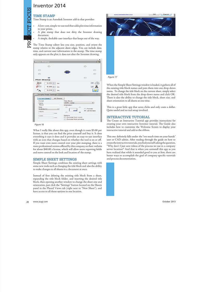
8122019 augi world 2013 10
httpslidepdfcomreaderfullaugi-world-2013-10 2252wwwaugicom October 20
SPECIALFEATUREAUGI Forums by Melanie Perr
The AUGI Forums are as always a busyplace Ask a question and you mightsee half a dozen varied methods andworkarounds posted in a single thread If
you have not had any questions yourself I would stilllike to encourage you to pop into the Forums and see
if there are any problems you could solve especially if you use one
of the less adopted products Tere will always be many helpinghands in the AutoCAD and Revit Forums but what about themechanical products or design visualization or structural detailingForums Peek in and see if you can share your experiences andwisdom with the community
I confess that I only scoured the English-speaking Forums forcontent for this article but please keep in mind that there areAUGI Forums available in 12 other languages so users have theoption of asking for support in their native tongue
AUTOCAD ndash SYSTEM VARIABLE
DISCUSSIONhttpbitly15M1hB9
Tis topic started out when a user couldnrsquot delete Te solution wasultimately the PICKFIRS variable but the discussion evolved tosafeguarding other variables automatically just to protect against aloss of settings in the event of a crash User Coloradomrg offeredthe safeguard shown in figure 1
Norton_cad also suggestsDIMLFAC EXPER andBLIPMODE be addedto the list
REVIT ndash
UNDERLAY
BEHAVIOR
EXPLAINEDhttpbitly15M1iFd
Mschroeder opened thediscussion with If you haveever wondered why some wallsdonrsquot show up in underlays or
show up inconsistently from floor to floor or why roofs and vieranges affect their behavior then read on
First rule of underlays Underlay view extent properties (cut rangdepth) are not user modifiable and not coupled to any othviewrsquos properties
Itrsquos also been mentioned ldquoIf objects are visible in the view ranof your current view AND in the view range of your Underlathey are automatically hidden in your underlay so there isnrsquotdouble instancerdquo
Users twiceroadsfool and dbaldacchino helped clarify the effecby posting sample models and pertinent data from the AutodeKnowledgebase and Autodesk Support Visibility View RangDetail Level and Cut Planes are all touched on in this discussioNeed clarity on how to make the most of Underlays Check inthis thread on the Forums
LISP ndash MAKING A DIALOG BOX RETAIN
ITS SELECTIONShttpbitly15JzMCc
Te LISP Forum always has such fascinating topics it is hato decide which to highlight From locking OSNAP options setting Explode options along with troubleshooting of existincode But the discussion surrounding the tutorials and metho
to retain selectioin a dialog box wvaried and lively so had to check it ou r e a v e s 0 4 4 1 3 2 1
even posted a sampdcl file when he wfinished
String Theory
8122019 augi world 2013 10
httpslidepdfcomreaderfullaugi-world-2013-10 2352October 2013 wwwaugiworldcom
AUGI Forums
AUTOCAD ELECTRICAL ndash LINES BEING
LABELED AS WIREShttpbitly1ew9p9D
Dinochrome says that one of his coworkers has reported aproblem with regular AutoCAD lines being labeled as wires
Crosswire35 advises ry checking your wire type edit dialogbox and make sure the ldquomake all lines valid wiresrdquo checkbox is unchecked
And IMCO goes on to say Using the vanilla line command inACADE will still place that line on a wire layer Change your linesto layer 0 and ACADE will not give them a wire number
AUTOCAD STRUCTURAL DETAILING ndash
TUTORIALShttpbitly17kW7cc
Te consensus is that this product is a little confusing to figure outand that most of the tutorials out there are older Most productshave a few videos floating around on Youube but this one doesnot seem to have too many yet
Jpo82 chimes in with I guess only tutorials forthis software are those found at Autodesk websiteTey are for versions 2010 and 2011 but still validhttpusaautodeskcomadskservlet12ampid=13111928 Irsquom not sure but sometimes I feel that the only new feature inASD 2013 is that itrsquos more stable than previous releases
Lucis29 goes on to say Also you might check some movieshttpwwwrobotofficecomasd but they are very old
Spenner then linked to his reporting of the Service Pack andissues it addressed hoping that it addressed some of the issuesthat came up in this discussion
NAVISWORKS ndash IMPROVE ANIMATION
EXPORT QUALITYhttpbitly1fQLoIv
Different methods are discussed from exporting individual imageframes to exporting a video (and how long) but I will leave youwith the following list from Revit For Breakfast
Here are the secrets to movies in Navisworks1 Donrsquot use materials ndash you make your render time much longer2 Use the PNG export option 15fps3 Make your video export twice as long as you need Ten speed it
up for a faux 30fps Tis is faster4 Look up the Navisworks blog by Lee Mullin and Paul Walker
about gooch and phong Tere is your faux render setting5 If you have NW 2012 you wonrsquot have gooch or phong but you
will have better export options 2013 has gooch and Phong butfewer export options
6 Te flickering occurs when multiple shapes overlap If you care
delete them in your export model Sometimes flickering occurs
in the generation of your frames on the PNG export You mayhave a frame that is ldquooffrdquo
7 Set your anti-aliasing to 4x or better on the png export8 Check out my old post httpforumsaugicomshowthread
php132209-Animation-Resolutionampp=1138298ampviewfull=1post1138298
CAD MANAGEMENT ndash NETWORK DRIVE
CHANGED BY IT WITHOUT WARNINGhttpbitly18J4k9c
Blackbox advises edinsmore595165 straight off to utilize theReference Manager program that comes with AutoCAD inorder to reconnect all of the external reference paths that werebroken when the I department upgraded their archaic serversHe further points out that moving from hard pathing to relativepathing would make things easier in the future
Feargt offers another twist Another option which would workon a need only basis when you open the specific drawing Change
XREF and Image paths in drawing to Network path throughscript on a need only basis Basically this will only change pathsPlace this line in a acaddoclsp file(command ldquoscriptrdquo ldquoyourserver and pathXREFREDIRECscrrdquo)and the following in a script fileREDIRB enter name of path to be replacedP enter new path
Tere was also a debate in this thread about obstacles and benefitsof user-managed and I-managed drive mapping
Melanie Perry is a Facilites-Manage-ment Coordinator and echnical Edi-tor in St Louis MO She is the AUGISalary Survey Manager and is curring-ly serving as an Officer on the Board ofDirectors Melanie can be reached atmistressofthedorknessgmailcomor found on witter asMistresDorkness
OTHER HOT TOPICSHave you found a Forum solution so mind-bogglinglyuseful that you leapt out of your chair with a whoopingcheer (or were at least tempted to) Please let me know Asingle person cannot read every post in our bustling AUGIForums so if you would like to see a thread highlighted ina future edition of String Teory feel free to let me knowSend me Wanderer a PM in the Forums or send an emailto MelaniePerryaugicom
See you on the Forums
8122019 augi world 2013 10
httpslidepdfcomreaderfullaugi-world-2013-10 2452wwwaugicom October 20
Revit Architecture 2014
PRO
DUCT
FOCUS
by Martijn de Rie
Myth Buster
Revit amp IFCPart 3
Irsquove given a lot of thought as to how this trilogyof articles should end At first I thought Irsquoduse the Coordination View 20 EXPRESS-GWallPaper for IFC2x3 (httpwwwmdr-
adviesnlwp-contentuploadsCoordinationView_V2-0_WallPaper_IFC2X3_Version-1pdf ) as a stepping stoneto give an ldquoIFC for Dummiesrdquo type of solution But that turnedout to be quite lengthy and rather boring But the link is includedabove for obvious reasonsmdashitrsquos useful
So I went back a little and asked myself ldquoWhy IFCrdquo And with thatquestion the inevitable follow-up immediately appeared ldquoWhynot IFCrdquo I realized that in the previous articles I failed to explainwhy in my humble opinion we should care about this somewhatcrooked badly implemented severe headache-inducing formatTerefore instead of explaining the fundamental technicalities ofIFC that can be explored in other places this final installment willexplore the Why versus Why Not IFC discussion and begin withthe latter
WHY NOT IFCWhen everybody uses Autodeskreg RevitregWell in this case itrsquos a no-brainer Share your Revit files Period
Loss of dataTis is an easier way to share data instead of hacking your wthrough IFC and praying your stuff doesnrsquot get lost in the proce
Even when you manage to export your geometry through IFtherersquos always loss of data
Loss of intelligence during importEven if you only need to send over geometry not data importithat into Revit makes it utterly useless All constraints are locomponent parametrics are gone and so on
Availability of bidirectional linksWhen not everyone uses Revit on a given project (which is quoften when yoursquore not located in the US) why not simply ua bidirectional linking between proprietary software standardTis can be easier and better to control
8122019 augi world 2013 10
httpslidepdfcomreaderfullaugi-world-2013-10 2552October 2013 wwwaugiworldcom
Revit Architecture 2014
WHY IFCWhich may be asked as why would you want to use IFC Or moreaccurately why would you want that option available
Consider what Sir Arthur Conan Doyle wrote ldquoOnce you eliminatethe impossible whatever remains no matter how improbablemust be the truthrdquo
Letrsquos put that to the test shall we
When everybody uses RevitOkay simple math Autodesk has around 7000 employees Teworld has about 72 billion people What are the chances someonenot working for Autodesk has a brilliant idea and creates thesoftware you need tomorrow Tere will always be better solutionsTey might not be viable for you overall but therersquos no reason toshut down access to them Revit is a wonderful generic tool forwhich I see a brilliant future with all kinds of additions for specificniche-markets like AutoCAD has
What about today DDS is MEP-engineering software that cando energy calculations (not simulations) inside your modelRhino lets you model things on the fly that could (arguably)take ages in Revitmdashif you ever get them done ekla lays wasteto the Revit structural rebar functionality any day of the weekwithout breaking a sweat Solibri is a wonderful solution for clashdetection and most importantly rule-based model checking andreportingmdashsomething Revit (or Navisworks) doesnrsquot do
Should I go on
Only problem for all this magnificent software Itrsquos either based onthe IFC format or requires model exchange through IFC
Te fact of the matter is there will always be better softwareAny one may be the software for you but that doesnrsquot mean yourpartners associates etc need to have the choice to use it forcedupon them
Loss of dataOn July 1 2013 there was an extra release for Autodesk softwareTe Sourceforge Open Source IFC Exporter released a new versionthat incorporated the option to map custom Revit parameters(shared or non-shared family or project even calculated values) totheir IFC counterparts
On September 28 2013 I had the honor of showing the secondstep in a complete and controllable data export from Revit
During my RC Europe class I showed the new option to create acustom IFC Property Set and map any given Revit parameter intoIFC fully customizable
IFC does not automatically lead to loss of data Tat idea is simplynot true Incomplete implementation in Revit does lead to loss ofdata As of now you are able to put any piece of data into an IFCeven calculated values And we didnrsquot change the IFC format We
just improved implementation in Revit
Loss of intelligence during importldquoJust because something hasnrsquot happened yet doesnrsquot meanitrsquos impossiblerdquo
I donrsquot know who originally had this insight and I doubt it to bethe movie line I remember but it is true
In the same RC Europe class I showed a native Revit familybeing exported to IFC altered and re-importedmdashwhile keepingall parametric constraints and even adjusting to the alterationsmade directly in the IFC file It is possible but not with thecurrent importer
Availability of bidirectional linksIrsquove been using Revit for almost 10 years now For 4-5 years I didnrsquotknow about IFC at all Before a year ago this was my strongestargument against IFC Why would you need a generic ldquolanguagerdquowith all its limitations (of which there are) weaker implementationand use of parametric capabilities (because it has) and lag-times indevelopment (by nature)
IFC will never be able to do what native software does simplybecause itrsquos responsive in nature Development budgets are afraction of what Autodesk rimble or Nemetschek get to spendon their software
So why not keep it simple and use a bidirectional link Revit has itwith a lot of other Autodesk software and third-party applications
But how long have we waited for them And are they even trulybidirectional Do they exactly do what you want them to do In myhumble opinion the answer to these questions is not very inspiringEven bidirectional links tend to have major limitations and severe
constraints in flexibility And most important Te link itself isalso propriety software No way of adjusting it to your needs
WHAT IF MORE PEOPLE STOPPED
TALKING ABOUT IT AND JUST GOT
INVOLVEDTe improbableFirst off itrsquos a matter of simple logic As Sir Arthur suggested ifwe can successfully check off all likely options to NO want touse IFC doesnrsquot that mean the improbable is true Tat IFC is infact a valuable tool in our toolkit and we should be able to use it
when necessary
Mind you Irsquom not saying you should use IFC If yoursquore on a Revit-only project it would be insane Just send and receive RVs Tefact is this will only be viable for limited parts of the buildinglifecycle If yoursquore lucky the entire design team is on Revit Butmanufacturers have other software facility managers too
As for the design team what if the best structural engineer is not[on Revit] or the MEP guy that has loads of experience in similarprojects Would you settle for second-best just because someoneuses the same brand of tools you do I wouldnrsquot
8122019 augi world 2013 10
httpslidepdfcomreaderfullaugi-world-2013-10 2652wwwaugicom October 20
PRO
DUCT
FOCUS
Revit Architecture 2013
Open AccessWhich brings us to the biggest advantage of IFC (or any open
format) itrsquos open Which means itrsquos adjustable to your needs Nowdonrsquot go ldquothatrsquos too difficult expensiverdquo Tatrsquos bullocks
Te first external enhancement to the Open Source Exporter wascreated by om Pesman a self-employed API specialist
Parametric IFCImplemented by Jon Mirtschin also self-employed IFCparametrics is available Agreed Jon is a well-known IFC guru butstill the point holds
Custom property sets and parametersWim as owner of a small MEP engineering firm hasadded functionalities toward this end and hersquos not even a trueAPI specialist
All these developments were done for free by altruistic volunteerefforts as part of the creation of the Dutch Revit Standards Andof course with the invaluable help of the Autodesk Open SourceIFC Exporter team Angel Velez in particular
But what if these guys actually got paid What if this projectwasnrsquot a Saturday night side-job What if more people stoppedtalking about it and just got involvedmdasheither by themselves or byleveraging experts to get what is needed Te entire IFC format is
Open Source the source code is out there which basically meansyou can do whatever you want and create whatever you needmdasheven on a project-by-project basis
BIM ITrsquoS THE ldquoIrdquo THAT MATTERSIn my humble opinion the entire debate on BIM is focusing on thewrong part of the acronym I donrsquot care if ldquoBuildingrdquo is a noun ora verb Nor do I care whether itrsquos ldquoModelrdquo or ldquoModelingrdquo nor am Icommenting on whether one should say ldquoBIM Modelrdquo
Itrsquos the ldquoIrdquo that matters If wersquore collaborating the Informationis most all I care about I just want your datamdashin the leanest
smartest and most effective way possible
A Revit model will do conversely a lot of times A Revit model w
give me heaps of data I donrsquot want geometry I donrsquot care about ana file format I canrsquot use Now we can all keep on being really anabout it or we can simply use the tools available to us one of thebeing IFC
A FINAL NOTEAs stated at the beginning of the article I really enjoyed writinthis series and for now this is the last of the series But if yoursquointerested in more tips and tricks on IFC let me know I might able to persuade the guys at AUGI to let me write about it againLord knows there is still a lot to talk about regarding IFC
Martijn de Riet is a self-employedBIM Consultant from the Nether-lands working with Revit since version51 Martijn has a bachelor degree inBuilding Science After his studieshe started his own engineering firmworking for contractors architects and
private clients Starting in 2007 hiscompany transformed into a full-timeBIM consultancy service At the mo-ment Martijnrsquos clients vary from mid-sized architectural firms to the largest
dutch General Contracter and MEPEngineering firms with a focus onspecific corporate solutions design andimplementations of Revit and BIMworkflows Martijn is a member ofthe Dutch Revit User Group and cur-rently working on creating a Masteremplate and Component LibraryHe provides lectures for companiestechnical universities seminars etc ona regular basis
Itrsquos the ldquoIrdquo that matters If wersquore collaborating the Information is most all I care about I justwant your datamdashin the leanest smartest and
most effective way possible
8122019 augi world 2013 10
httpslidepdfcomreaderfullaugi-world-2013-10 2752
wwwxicomputercom
8122019 augi world 2013 10
httpslidepdfcomreaderfullaugi-world-2013-10 2852wwwaugicom October 20
3ds Max 2014
PRO
DUCT
FOCUS
by Chris Murra
SUMMARY WHATrsquoS
CUSTOMIZABLE IN MAX
(HIGH LEVEL)When it comes to the customizability of Autodesk 3ds Maxregitrsquos no secret that it can morph itself into whatever you want theprogram to become
Whether yoursquore a modeler animator lighter rigger generalist ortechnical artist 3ds Max can become your own personalized toolbox that is an extension of your own hand in your daily workYou can now combine different command types (such as creatingobjects and object modifiers) into a single menu reducing themouse travel and improving efficiency
In this article wersquore going to take a closer look at one specificaspect of customization with 3ds Max the new enhanced UI Aspart of this article besides taking a deep dive into the operationof this feature I will also be showing how I created the ldquoMographrdquo
tools UI that includes custom buttons and icons At the end this article I will also provide a link to this UI so you can use customize it yourself or share it with others
ENHANCED UI SUMMARYWhat is the Enhanced UI
Te Enhanced UI is a new graphical user interface system thdoes two main things
1) It provides a refreshed 3ds Max user interface with updattool categories and new clusters of pre-existing tools in groupinthat are more akin to their intended purpose as opposed to somtechnical requirement for menu placement
2) It provides a way to allow you the end user to customize thmenu system in almost any way you choose Te drop-down menare ldquotear-ablerdquo (not to be confused with ldquoterriblerdquohellip but I digresand the resulting configurations are savable either by scene or
3ds MaxEssentialsCustomizing
the UI
8122019 augi world 2013 10
httpslidepdfcomreaderfullaugi-world-2013-10 2952October 2013 wwwaugiworldcom
3ds Max 2014
a preset Tey are also distributable and deployable so they can beshared with others
Where is the Enhanced UITe Enhanced UI can be found in the upper left hand corner of themain UI at the very top of the screen Tere is a drop-down menuthat says ldquoWorkspace Defaultrdquo Tis default is the same baselineUI that ships with all 3ds Max installs (Figure 1)
Within the drop-down you can find the ldquoDefault with EnhancedMenusrdquo Tis is the alternative default menu system that youcan use on its own or use as a starting point to create your owncustomized menus
BASIC DEFAULT CUSTOMIZATIONEnhanced UI Customization BasicsNow that wersquove enabled the Enhanced UI how can we change it
SOP Before you begin mucking around with the UI Itrsquos importantto understand what I call the ldquosave-logicrdquo as it pertains to custom UIs
Te UI Save LogicIf you plan on saving this UI for future use there is a specificmethod you must follow to properly save the UI you want and notwreck the default Enhanced UI
Te Save Logic is as follows Itrsquos simple but important
Step 1 urn on Enhanced Default UI (Figure 3)
Step 2 Click ldquoSave as New Workspacerdquo FIRS At this point youwill be prompted for a new name (Figure 4)
Step 3 Edit and change the UI at will
NOE All future edits are ldquoautomatically rememberedrdquo as you go (Iintentionally did not use the word ldquosaverdquo)
Step 4 Te ldquosave as default staterdquo button is important When wehave completed the customization process we then choose thisbutton to ldquolockrdquo in the changes Tis is different than Saving a UIwith a custom name
HO IP ldquoBut this methodology seems backwardrdquo
I can see how yoursquod say that but remember that any changes you make
to any enhanced UI are automatically ldquorememberedrdquo If you create acustom UI then while working you make some temporary changeswhen doing something specific those little changes are automaticallyremembered If you want to return to the default state [of yourcustomized UI] you select ldquoReset to default staterdquo Tis does NObring back the default Max UI rather it brings back the customizedUI you created in ldquolockedrdquo in Step 4
Okay now that you have the save logic down letrsquos begin customizing
1) If you havenrsquot done so already turn on the Default Enhanced UI
2) Go to ldquoManage workspacesrdquo from the drop-down and in the
Figure 1 Workspaces are in the Workspace drop-down menu
Figure 2 Default UI (left) and the Default Enhanced UI (right)
Figure 4 Saving the New UI Workspace
Figure 3 Turning on the Enhanced Default UI
8122019 augi world 2013 10
httpslidepdfcomreaderfullaugi-world-2013-10 3052wwwaugicom October 20
3ds Max 2014
PRO
DUCT
FOCUS
Manage workspaces dialog choose ldquoSave as new Workspacerdquo Giveit a specific name
3) Begin making your desired changes
Since a custom UI is specific to any one individual letrsquos take a lookat what types of customizations can be made
Simple ChangesOne of the simplest things to do is peel off any commandgroup (see Figure 5) Just click the group title bar and drag Tecommand group becomes a floating dialog box Now just becauseyoursquove peeled it off does not mean that yoursquove removed it fromthe drop-down menu Te ldquooriginalrdquo command group remains inthe drop-down You can just close the floating dialog when yoursquoredone with it
Probably the simplest thing you can do is reorganize the menusIn each drop-down menu appears a group of commands You maynotice that some command groups are icons and some are words(Figure 6) o change the appearance of the commands there is asmall icon in the upper right corner of each group of commands(Figure 7)
Te next change is alreally simple Is tcommand group op(expanded) or clos(rolled up) Just clion the plus or minsign in the upper le
corner to set this stafor the next time yolaunch 3ds Max (Figu8) Remember thesettings are saved as yogo so whether it is opor closed is your choicbut the state the menis in when you cloMax is the one that remembered the netime Max opens
What about Saving tDefault state More othis later
Once you have floating menu yocan combine differecommand groups dragging any othcommand group to aother floating dial
that yoursquove created Tis makes for easy creation of custom dialo
based on specific tasks Figure 9 shows a command group fcharacter animationFigure 5 A floating menu that has been torn off the drop-downmenu
Figure 6 The different display states of the menus
Figure 7 Changing menu layouts
Figure 8 Rollouts
8122019 augi world 2013 10
httpslidepdfcomreaderfullaugi-world-2013-10 3152October 2013 wwwaugiworldcom
3ds Max 2014
ADVANCED CUSTOMIZATION
What about completely custom interfaces Herersquos how we do thatwith the Enhanced UI menu system
Te following is the high-level overview of the process Wersquoll thenunpack each step in more detail
If you havenrsquot read the section on Basic default customizationplease do so before continuing Before starting this phase ofcreating your new UI you should have saved your new UI stateTat process is explained in the previous section
1) Create a main drop-down menu (like ldquoMy oolsrdquo)
2) Create a tools category menu into which you will place yourtools (a submenu such as ldquoModeling oolsrdquo or ldquoAnimation oolsrdquo)Drop-downs can have more than one subcategory
3) Add commands to various submenus
4) Clean up the UI by creating custom names adding separatorsor creating custom icons
First letrsquos create a new menu for the menu bar Tis is done easilyfrom the CustomizegtCustomize [Rollout]gtCustomize UserInterface dialog box
Steps for Creating a Drop-Down Menu1) Create a New Menu and give it a name (see Figure 10)
2) Locate your new menu in the Menus window It will be listedalphabetically (Figure 11)
Figure 9 Multiple command groups in one menu
Figure 10 ndash Creating a new drop down menu
Figure 11 Location of new menu
8122019 augi world 2013 10
httpslidepdfcomreaderfullaugi-world-2013-10 3252wwwaugicom October 20
3ds Max 2014
PRO
DUCT
FOCUS
3) Drag your newly created menu category over to the column onthe right Tis will add your new drop-down menu to the interfaceimmediately and you can begin populating it with menu items (seeFigure 12)
UI DESIGN IP Te actual menu name and display name can bedifferent I used a custom menu name behind the scenes so I couldeasily differentiate my menus from the ones created by default or other
tool companies After you create a menu and add it to the right column you can right-click on it and change its display name (see Figure 13)
Next letrsquos create a command group1) Just like in Step 1 from the previous section create a new men
2) Tis time before you drag it to the right column click thplus sign next to your drop-down menu item to expand it Tedrag the new item to the right column dropping it ldquounderrdquo thmenu name
3) Drag any commands from the Commands window on the leto the submenu on the right (see Figure 15)
Herersquos an example from my Mograph ools workspace thshows how a completed menu looks once it is created (Figu16) In the following figure you see both the menu as it appeain the Customize UI dialog and the actual menu (which has bepeeled off)
Notice that some of the commands on the menu are greyed ouTatrsquos because this new menu combines both ldquoObject creatcommands and ldquoObject Modify Commandsrdquo in one menTey will remain grey until you create an object on which thwill be used
Figure 12 Adding the new menu to the UI
Figure 14 Creating a command group
Figure 15 Dragging commands onto the menu
Figure 13 Custom menu names
8122019 augi world 2013 10
httpslidepdfcomreaderfullaugi-world-2013-10 3352October 2013 wwwaugiworldcom
3ds Max 2014
Adding SeparatorsSeparating commands is easy and is recommended to help you oryour intended user make sense of the how the tools are arranged inthe menu Creating a separator is as easy as dragging one over theright column just like a menu or command
HO IP ldquoWhy do I need to create another menu Why canrsquot I addtools right to my menurdquo
Te main reason is that adding a submenu gives you the ability to tearoff the submenu If it werenrsquot in a submenu it wouldnrsquot be tear-ableSo itrsquos really a ldquobest practicesrdquo kind of thing But even if you try to notadd the submenu it will happen automatically Itrsquos important to do it
explicitly so you are aware of what submenus are in the menu and that you are the one in control of what command is going where
CUSTOM ICONSNo custom UI is complete without a custom set of iconsAdditionally not all commands in 3ds Max have their own iconyet But itrsquos important to realize that regardless of how you set up
your UI yoursquore still working within the framework of an existingapplication and there are boundaries to what you can edit andcreate Icons have specific requirements both in their creation(size) location and file name that must be adhered to in order forthem to work properly
SizeformatTe size of icon is pretty simple It must be 32x32 pixels andPNG format
LocationTe location is very specific New icons must be added to thislocation
CProgram FilesAutodesk3ds Max 2014UI_lnResourcesDarkIconsMain
Te new icons I created for the Mograph UI are shown inFigure 17)
Icon File NameIf yoursquore still with me at this point we are now getting into thenether regions of customizing a UI Tis is where things get a littletricky but itrsquos really not too bad File names are specific and aregenerated by the application (3ds Max)
So letrsquos begin First identify the command for which you want aniconmdashusually itrsquos one that doesnrsquot already have an icon But if itdoes and yoursquore changing it MAKE A BACK UP of the originalicon PNG file Tis is because as previously stated you donrsquot havecontrol over the file name Tat means if yoursquore creating your ownicon you need to overwrite the existing one and use its name foryour new icon So back up any original icons
Figure 16 The completed menu
Figure 17 ndash The created icons
8122019 augi world 2013 10
httpslidepdfcomreaderfullaugi-world-2013-10 3452wwwaugicom October 20
3ds Max 2014
PRO
DUCT
FOCUS
It really doesnrsquot matter whether you make the icon first or not ofind the name you need to use you need to navigate as follows
NOE Yoursquore about to edit the ribbon Tere is no need to save thesechanges as we are merely extracting information from it But if yoursquoredoing a lot of custom icon work you may want to save this change to theribbon so you can come back and continue your work in later sessionswithout have to recreate this every time just to get the proper file nameSaving this ribbon is not related to saving your default state of yourUI When yoursquore done creating all your UI icons you can just delete
whatever changes you make to the ribbon
1) Open the ldquoCustomize Ribbonrdquo dialog box
2) Create a new ldquotabrdquo by dragging it onto the ldquoExisting Ucolumn in the middle (see Figure 18)
3) Using the same drag method add a new ldquopanelrdquo to ttemp tab (Figure 19)
4) Now you can get the information you need Find tcommand for which you are creating an icon and dragto the panel
5) Locate the ldquoinfordquo portion of the ldquoPreview Windocolumn At the bottom of the column is the file namneeded to have the icon used properly by the applicati(Figure 20)
CONCLUSIONSo now you know how to create a custom UI scheme f3ds Max 2014 and up By using the Enhanced UI me
system itrsquos really easy to generate a multitude of workspathat allow Max to work the way you want to work
Te example used in this article was the ldquoMographrdquo UI thI created for NAB 2013 If you would like to downloand install it you can get it from my ldquoPinning the Stacblog on the Area herehttpareaautodeskcomblogschrismurray
Enjoy
Chris Murray works for Autodesk
Media amp Entertainment He istrained as an animator (3D variety)but considers himself a creative tech-nologist His daily role is a technicalldquoevangelistrdquo for Autodesk creating marketing deliverables for 3ds Max Heis the author of Mastering 3D StudioMax He has a Masters in Fine Arts(MFA) in Computer Animation fromMiami International University of Artand Design Follow him on witterchrismmurray
Figure 18 Creating a tab on the ribbon
Figure 19 Adding a panel to the tab
Figure 20 Finding the required file name
8122019 augi world 2013 10
httpslidepdfcomreaderfullaugi-world-2013-10 3552
AUGIMembersReach Higherwith ExpandedBenefitsAUGI is introducing three new Membership levelsthat will bring you more benefits than ever beforeEach level will bring you more content and expertiseto share with fellow members plus provide anexpanded more interactive website publicationaccess and much more
MEMBERMEMBER MEMBER
Basic members haveaccess tobull Forums
bullHotNews (last 12 months)
bull AUGIWorld (last 12 months)
DUES Free
Premier members haveaccess tobull Forums
bullHotNews (last 24 months)
bull AUGIWorld (last 24 months)
DUES $25
Professional members haveaccess tobull Forums
bullHotNews (full access)
bull AUGIWorld (full access and in print)
bull ADN 2013 Standard Membership Offer
DUES $100
Are you ready to upgrade yourself and your membership
Access additional benefits and upgrade at wwwaugicom
8122019 augi world 2013 10
httpslidepdfcomreaderfullaugi-world-2013-10 3652wwwaugicom October 20
AutoCAD MEP 2013
PRO
DUCT
FOCUS
by Vladimir Triantafillid
BIM IsWhatrsquos
Driving theIndustry
For the past decade many would arguethat building information modeling(BIM) has metastasized aggressivelythroughout the AEC industry but what
does BIM really mean More importantly whatdoes it do for us and for our industry Ask someone who hasbeen in this industry for more than 25 years or those nearingretirement and yoursquoll find that less than half see its value muchless care to make the effort with its implementation hesequestions mean something different for those who have beenin the industry the past 10-15 years Recent college graduates
however with their tech-savvy capacity and high expectationare eager to implement anything that resembles cutting-edgflashy technology ypical ly they are the ones most receptivenot adamant about putting their talents to use through BIM
I recently gave a BIM presentation with an emphasis on mchanical systems to the summer interns and new hires our companymdashall were non-BIM users except for onemdashbmy presentation did little justice to BIM Half of my audence had found a cure for their insomnia when they realizthis wasnrsquot the latest edition of ldquoCall of Dutyrdquo hat was n
8122019 augi world 2013 10
httpslidepdfcomreaderfullaugi-world-2013-10 3752October 2013 wwwaugiworldcom
AutoCAD MEP 2013
reflection on BIM by any measure Simply put I fell shortof connecting with a potentially captive audience eager toknow what really makes BIM intriguing or how it wouldgive them an edge in the industry I didnrsquot think to look pastpresenting the facts of its processes and benefits o simplyhave stated that proficiency in any of its many facets willpromote a lucrative career would give those still awake theimpetus to jump ship In hindsight the first step I shouldhave taken to begin this presentation was to ask what theywanted to get out of BIM
If you think itrsquos hard conveying the value and splendor ofBIM to receptive and impressionable young minds try toconvince the weathered veterans dead-set in their ldquooldtricksrdquo For every experienced veteran who has converted toBIM there are two ldquoold dogsrdquo that canrsquot shake ldquothe good olrsquodays when we used vellum and light tablesrdquo Guess whatmdashanincreasing amount of naysayers are starting to come aroundincluding those who say theyrsquove been burned by BIM in thepast hey are seeing the simple solutions BIM presents and
how these solutions translate into cost savings More andmore of those who had formerly questioned BIMrsquos utility areconvinced when installation efficiencies are not only real-ized but quantified
Another factor in the evolution of BIM is its tendency toexpand faster than the pace of its general population of us-ers hose of us proud to be catching up to what we think iscutting edge quickly realize it was just another false sense ofaccomplishment as BIMrsquos web continues to grow exponen-tially he solution is rather simple Focus on what you canhandle and always have the presence of mind and sense ofcaution to avoid being overwhelmed by the wake of BIMrsquos
progress herersquos plenty of money to be made and countlessfacets to explore as long we have the following mentality Welive in the information age and those wi lling to share knowl-edge will reap the rewards of communal synergy
On the opposite end of the spectrum you might find ourindustryrsquos opportunists In a hurried frenzy to claim theirspot in the intellectual property queue these opportunistsget carried away with pioneering what they assume is the lat-est improvements to BIM Instead of stopping to absorb anddevelop the benefits of 4D 5D 6D and so on the pioneersare spreading these ldquoDsrdquo thin with abandon further expand-
ing the gap between quality and quantity None of this i s tosay that wersquore heading in the wrong direction On the con-trary letrsquos call it more of a positive economic problemmdashthedemand for BIM expertise and development outweighs thesupply of available users
Fortunately as collegiate curricula catch on to this industrytrend the point of equilibrium will soon follow For as longas I can remember respective companiesrsquo 2D CAD depart-ments have been a significant source as the breeding groundfor potential BIM users While this route hasnrsquot changedregarding the career path of a draftsperson the source poolhas expanded to include architects engineers and construc-
tion managers just to name a few Itrsquos even hard not to noticeits stark demand when BIM and Revit courses are being in-creasingly offered at local community colleges I knew thenthat you didnrsquot necessarily need an undergraduate degreeback when I got my foot in the door of this industry hisprobably wonrsquot hold true in the coming years Still the privi-leged few who are already a part of this industry subset canrely on their experience in this fast-paced market to con-tinue to propel their careers forward ever faster All thesefew need to do is grab onto a small piece of BIMrsquos wing andhang on tight for the ride he fresh-out-of-college e ntrantsmight have a harder time grabbing onto this wing thatrsquos al-ready in motion
o those who are only vaguely famili ar with BIM it is typi-cally perceived as the equivalent of a 3D role-playing videogame In this case itrsquos not difficult to capture a ldquosnapshotrdquoimage of a 3D model shadows cast across random metal ob-
jects taking up space in an orderly fashion between ceil ingspaces and walls What is difficult is conveying the abun-dance of value behind the pretty picture to a client whorsquosonly interested in the pretty picture Who isnrsquot familiar withthe adage ldquoa picture is worth a thousand wordsrdquo Why notchange that saying to ldquoa BIM model is worth five thousandhyperlinksrdquo Now wersquore talking lifec ycles and facilities man-
More and moreof those who had
formerly questioned
BIMrsquos utilityare convinced
when installationefficiencies are notonly realized but
quantified
8122019 augi world 2013 10
httpslidepdfcomreaderfullaugi-world-2013-10 3852wwwaugicom October 20
AutoCAD MEP 2013
PRO
DUCT
FOCUS
agement his supposed video game has suddenly becomean encyclopedia of usable information But wait itrsquos not juststatic information thatrsquos stuck on a DVD on a shelf i n someownerrsquos random storage closet It has now become a livingdynamic source of real-time data Maintenance technicianswill know exactly where to go when the active 3D modelloaded on their laptop highlights a hot water pump needingservice while concurrently bringing up the cut sheets andoperation and maintenance manuals specific to that pumpor system Better still the source of information has shiftedfrom multiple stacks of large drawing sets collecting dust toseveral hundred gigabytes on a hard drive Yes Mrs Clientyour 3D BIM model will be usable for the next 20+ years
Even though you might not necessarily think about i t someof you probably realize that BIM has become the ldquomiddle-manrdquo for so many key components in the construction cyclewell beyond its intermediary role between design and con-struction phases You want to do some significant tenantimprovement in an existing building Laser-scan the exist-ing conditions hatrsquos BIM Is the general contractor rackingtheir brain trying to f igure out where to station the crane forthe project or pave the pathways for delivery trucks Nowtheyrsquore looking to BIM to answer these questions and opti-mize their decisions o take it a step further at which endof the building do we want to load thousands and thousands
of pounds of sheet metal and pipe And then which tradesshould be installing their systems first in any given area ofthe building hatrsquos right wersquore deriving sequencing andtimelines from the BIM model to e stablish the best routes totake while addressing any constructability issues BIM hasbecome the consultant that wears most of the hats Itrsquos ourone-stop shop
I know that Irsquove personified BIM as if itrsquos the brains behindall of its success Letrsquos take a moment to focus instead on itscollaborators or the sum of its integral parts to show thatin reality we are Dr Frankenstein and BIM is our monster
Except in our ca se wersquore beginning to ta me our monster anthose who were previously frightened by it are starting to sthat it indeed is no monster In fact while evolving to domdashand becomemdashgreater things BIM is transforming into aindustry hero he point of convergence is approaching bcause wersquore saving money time and even trees Soon enougBIM will be the industry standard even on the smaller proects Letrsquos keep the pedal to the meta l
You want to know the best news Most of us havenrsquot evebegun to scratch the surface of BIM but wersquore in strategpositions to reap the rewards aking the possibility of ivast potential into account isnrsquot it reassuring knowing th
in these tough economic times wersquore engaged in an industthat has a shortage of well-qualified BIM experts Our eposure alone sets us up for success Now ask yourselves thquestion Is BIM driving our industry or is it the BIM use
Vladimir riantafillidis works for aleading mechanical contractor in theSan Francisco Bay Area with morethan 10 years of experience in the in-dustry Although he has a bachelorrsquosdegree in biology his unique careerchoices have firmly rooted him in a
substantial BIM role awarding himthe opportunity of progressing along-side the relentless evolution of BIMOutside of his career hersquos always opento new adventures whether trying anew cuisine exotic travels or extremesports Te latter adventures have re-cently subsided as the balance of lifehas shifted his focus on spending timewith his growing family
You want to know the best news Most of us havenrsquot
even begun to scratch the surface of BIM but wersquore
in strategic positions to reap the rewards
8122019 augi world 2013 10
httpslidepdfcomreaderfullaugi-world-2013-10 3952
8122019 augi world 2013 10
httpslidepdfcomreaderfullaugi-world-2013-10 4052wwwaugicom October 20
Revit Structure 2014
PRO
DUCT
FOCUS
Streamlining
Sheet Listswith a Custom
Application
In this article we take a brief look a simpleadd-in for Autodeskreg Revitreg named X-Sheetswhich provides tools for incorporating sheetsfrom an AutoCADreg sheet set in a Revit sheet
list ypically this is handled by manually addingplaceholder sheets to the Revit sheet list Tis can be problematicbecause the sheet list becomes disconnected from the sourceand must be updated manually With X-Sheets sheet set datais exported directly from AutoCAD linked to a Revit project
and included in the sheet list by automatically addingupdatinplaceholder sheets For this example all structural scheduleplans elevations and section sheets are in Revit Structure Adetail sheets will be pulled from an external AutoCAD sheet set
X-SHEETS RIBBON PANEL Te first command on our ribbon panel is Discipline Tcommand is used to establish the Revit project parameter twhich the AutoCAD sheet subsets will be mapped For th
by Jonathan Albe
Figure 1 Revit X-Sheets ribbon panel
8122019 augi world 2013 10
httpslidepdfcomreaderfullaugi-world-2013-10 4152October 2013 wwwaugiworldcom
Revit Structure 2014
example we have created a project parameter named My DisciplineParameter Each Revit Structural sheet has been assigned a valueof SRUCURALmdashthe same as the subset name for theAutoCAD detail sheets Te sheet list is grouped and sorted bythis parameter
Te next command on the ribbon panel is Links Tis command isused to establish a link between the Revit project and XML file(s)
containing sheet information exported from AutoCAD You cancreate as many links as needed and use relative paths if required
Te next two commands Sheets and Update do the work ofaddingupdating placeholder sheets to the sheet list While theSheets command allows you to select individual sheets from linksto include in the sheet list the Update command includes all sheetsfrom all links
EXPORT SHEETS FROM AUTOCADFigure 3 shows the AutoCAD X-Sheets ribbon panel and asample sheet set containing structural detail sheets Notice thedetail sheets are grouped under a subset named SRUCURALTis subset name can be exported with each sheet and mapped to
the My Discipline Parameter in Revit Figure 3 shows the ExportSheets dialog with an option to include subset information and theability to exclude individual sheets Selecting the Export buttonprompts us with a dialog to save an XML file to be linked into ourRevit project
Figure 2 Discipline command dialog
Figure 3 AutoCAD X-Sheets ribbon panel and sample sheet set
Figure 4 Export sheets dialog
Figure 5 Export complete
8122019 augi world 2013 10
httpslidepdfcomreaderfullaugi-world-2013-10 4252wwwaugicom October 20
Revit Structure 2014
PRO
DUCT
FOCUS
ESTABLISH LINK TO XML FILE IN REVIT
PROJECTFigure 6 shows the Manage Links dialog A link has been added tothe XML file we generated when exporting sheets from AutoCADNotice there is an option to make the link path relative to our
Revit Project location
IMPORT SHEETS FROM XML LINKFigure 7 shows the Revit Structure sheet list before any sheetshave been imported from AutoCAD After selecting the Sheetscommand we are prompted with a Manage Sheets dialog
For this example we have selected all sheets from the XML linto include in our sheet list After confirming the dialog neplaceholder sheets are immediately added to the sheet list angrouped according to the SubsetDiscipline mapping Te neplaceholder sheets are identified behind the scenes as being relatto the X-Sheets XML link for later updating
Figure 6 Manage Links dialog
Figure 9 Sheet list after import
Figure 7 Sheet list before import
Figure 8 Manage Sheets dialog
The X-Sheets
add-in is a great tool
for incorporating
AutoCAD sheets into
a Revit sheet list
8122019 augi world 2013 10
httpslidepdfcomreaderfullaugi-world-2013-10 4352October 2013 wwwaugiworldcom
Revit Structure 2014
UPDATE SHEETSFigure 10 shows the Export Sheets dialog in AutoCAD afterdetail sheets have been renumbered to include ldquo-Ardquo When changesare made to AutoCAD sheets the original export steps must befollowed to replace the XML file linked to our Revit project Oncethe XML has been replaced simply run the Update command inRevit to update the sheet list
SUMMARYTe X-Sheets add-in is a great tool for incorporating AutoCADsheets into a Revit sheet list Te add-in saves time by automatically
adding placeholder sheets eliminates room for error in manualtranslation and helps to keep your sheet list up to date withminimal effort
Jonathan Albert is co-founder of BIM- pulse echnologies LLC amp SeniorApplications Developer at LindemanBentzon Bojack Engineering in Cler-mont Florida He has worked morethan 15 years implementing and usingBIM echnology for some of the na-tionrsquos leading production home build-
ers Most recently he has developedBIMpulse an Options Managementand Material akeoff Add-In for Au-toCAD Architecture Revit and Au-todesk Design Review Jonathan can bereached at jonalbbecom
Figure 10 Export Sheets dialog after sheet renumber
Figure 11 Update complete
Figure 12 Sheet list after update
The X-Sheets
add-in is agreat tool for
incorporatingAutoCAD
sheets intoa Revit
sheet list
8122019 augi world 2013 10
httpslidepdfcomreaderfullaugi-world-2013-10 4452wwwaugicom October 20
AutoCAD Civil 3D 2014
PRO
DUCT
FOCUS
by Tench Tilghma
Itrsquos a fact Jack You invested money in the worldrsquosmost popular civil engineering and designsoftware You (or someone else) will have workhard to make the software run productively
and publish the engineering design or surveywork acceptably
Every AutoCADreg Civil 3Dreg user will tell you ldquoYou need a Civil3D templaterdquo
heyrsquore right sort of You need more than one he suppliedexample Autodesk template files (dwt) are just thatmdashexamplesto show you that things are possible A great many ldquothingsrdquo arepossible in Civil 3D It is data-centric model-based software Asa dedicated content developer and continuous customizer of Civil3D I hope the following perspectives and tips help shorten thecycles and reduce the pain of customizing the software
AutoCAD Civil 3D was constructed from the ground up todisconnect the survey and engineering data from how that missioncritical data is represented
WITH LIBERTY COMES RESPONSIBILITYAs far as Autodesk is concerned what you want the many Civil 3Dldquothingsrdquo to look like and how the Civil 3D data is to be annotated istotally up to you hatrsquos not really true is it Plan sets are publishedin arcane symbolic graphic languages designed to faithfully conveythe design intent to someone who must build it with a plan checkeror two (or three or four) stuck in between
As a professional I prefer to call them ldquoPlan Set Languagesrdquo hhelps focus the development to the publishing of Civil 3D datMost people throw a fuzzy word around this complex mix human perceptive agendas and call that ldquoCAD Standardsrdquo
ldquohe wonderful thing about standards is there are so many of themndash Grace Hopper et al
PICK A STANDARD AND MANAGE BY ITldquoWe already have a CAD standardrdquo his may be the first anworst Civil 3D customization mistake any skilled AutoCAD usor organization can make he odds are the CAD standards yoemployed before do not take into account the data centric anmodel-based methods that Civil 3D employs Simply put Civ3D manages how things look and behave by Style Primitive-basAutoCADreg standards may get in the way
Older ldquoCADrdquo standards by definition must be focused on CAprimitive publishing specifics layer textstyle (height) blo
CustomizeCorrectly
Figure 1 Standards documentation is required
8122019 augi world 2013 10
httpslidepdfcomreaderfullaugi-world-2013-10 4552October 2013 wwwaugiworldcom
AutoCAD Civil 3D 2014
graphics standards and so on In raw AutoCAD and AutoCAD-based drafting and design software the only way to manage all theCAD primitive stuff was to be SPECIFIC about all the details allthe time he drawing we create and check things in is the drawingwe publish
If you publish work out of quality control or design drawingsin Civil 3D this is a sign you may be missing some of its timesaving advantages
While the old CADD process works it requires a lot of man-hoursdedicated to maintaining and checking the details Clearly one ofCivil 3Drsquos critical design development goals is to rid organizationsand Civil 3D users of this expensive man-hour burden and costhe idea here is to put the man-hours into the iterative engineeringprocess instead Civil 3D Feature data and Style make this possible
Civil 3D styles and label styles do employ the AutoCAD layertextstyle block references AutoCAD customizers are used tohe software is still called ldquoAutoCADrdquo Civil 3D after all Our
AutoCAD customization skills still apply But we must applythem differently and much more systematically Herersquos whyhellip
YOU NAME ITmdashTHE MOST CRITICAL
STANDARDCivil 3D Styles and label styles employ (reference) the AutoCADldquonamedrdquo parts to ldquoexpressrdquo themselves Style tools just look for andmatch the ldquorightrdquo names Change the ldquomeaningrdquo andor definitionof the names and you can change anything
We call this fundamental property and benefit of object-orientedprogramming the Power of Names In programming speak this
concept and practical reality is called a ldquonamespacerdquo
Such a namespace in engineering speak answers the questionldquoIn this context does ldquoDIrdquo means a ldquodrop inletrdquo In a minute wersquollget to the structure of a customization ldquonamespacerdquo for Civil 3DAutoCAD references
THE POWER OF NAMESGo ahead and make a drawing from your current Civil 3D templateoss in some Civil 3D data by data reference from any projectUse the RENAME command on any of the old AutoCAD stylecollectionsmdashtry layers
Rename like crazy Your existing Civil 3D styles and label styles willhappily work exactly the same he components in the Civil3DFeature and Label Styles will go to your renamed layers Becauseyou didnrsquot change the properties of the layers either nothingchanges Itrsquos not too exciting until you think about what it means
FOLLOW A SCRIPTObviously as customizers we never want to do this sort of workmanually Computers are faster better and more exact typists thanwe are We commonly rely on AutoCAD scripts generated from
Microsoft Excel spreadsheets (See the end of the article)
here are a couple of key collections in the object model thatCivil 3D walls off from this form of potentially destructiveuser madnessmdashObject Properties in Drawing Settings and afew things like Figure Prefix Dbs values that are not ever in thedrawing per se
WHAT REALLY MATTERSAutoCAD Civil 3D style is mind-boggling abstraction Everythingis designed and built to point at references We can employ styleabstraction for our benefit
In one sense AutoCAD Civil 3D style doesnrsquot care aboutAutoCAD layer standards block libraries textstyles colorsplotstyles or really anything else AutoCAD From our perspectiveall the Civil 3D styles care about are the arbitrary and exact namesthey currently reference
he Civil 3D customizerrsquos dilemma Keep book on the exactnames here are a lot of names to keep track of You must havea plan You must have rules You must employ the same processesconsistently in the same order to get quality assured results
Figure 2 Are description keys a namespace
Figure 3 Rename the AutoCAD reference names
8122019 augi world 2013 10
httpslidepdfcomreaderfullaugi-world-2013-10 4652wwwaugicom October 20
AutoCAD Civil 3D 2014
PRO
DUCT
FOCUS
hat Current word is a wonderfully relative term forthe customizer
Build a set of styles extract them to another drawing rename andor redefine the references and quickly produce a different resulthe Current method makes it easy to propagate success andmistake It makes it repetitively tedious to make fixes
NO CAN STOPAs innovative content developers for Civil 3D we chose to employthe National CAD Standard (NCS) as our fundamental Namestandard Not because we like the NCS but because of all thehard-won experience expressed in these tested standards Inmany respects we employ the NCS UDS (Uniform DrawingStandards) etc in our Production Solution products becauseof the underlying How and Why for those standards and theirpractical published Rules
We want to build faster high-performance vehicles Why reinventthe wheel when we can improve on it
STANDARD KEYS TO NAMEShe NCS employs a hierarchical concept of Keys here areMajor Keys Minor Keys etc that have order precedence and aninterpreted meaning he NCS Layer standard employs the Key-based rules to produce defined meanings to Layers
You can in practice employ the same Layer Keys to be genericor granularly specific about where the published results go Allthe annotation can go to one layer or many different layers forexample Styles andor sets do the work
his KEY CODE structure produces a flexible and structuredldquonamespacerdquo we referred to earlier Itrsquos a namespace that both thesoftware can employ and is relatively easy for us dumb-bunnyhumans to learn to decode when we must Most of the time theusers donrsquot and shouldnrsquot care anyway
Figure 4 shows a few of the NCS ldquolikerdquo Keys we employ in ourproducts We employ them for both layer and block collectionsand even the structure of libraries hey may even be employedin Civil 3D style names when thatrsquos appropriate (See the endof the article)
he customizing key point is that the meanings of these specificKeys can be translated into any other set (or sets) of different
Keys he Key changes can be systematically applied to whatevAutoCAD reference tables and resources we require
he results of any changes will float uphill to the named Civil 3Styles we choose to employ hink of all the AutoCAD referencin a template as a Set
BEYOND AUTOCADNow wersquove looped back to Civil 3D style tools and substantivetheir names and what their parts refer to Welcome to the circuland iterative world that is customizing and employing Civil 3D
Aside from the requisite customization skills and experience build style tools our practical biggest customization issues afrankly Civil 3D human interface issues
No matter how you cut it you have a very limited amount of tespace to help users decide on the ldquorightrdquo style tool to use he teof the style toolrsquos name is all you get to deliver to the user ypicaitrsquos a pick box list
You might get lucky and have the Style Viewer but that Viewcannot represent everything a style can do
FEATURE STYLES NAMESWhat we call the ldquoFeature Stylesrdquo (the Ci3D Featurersquos graphics) require that our stynames explain in simple readable humterms what the tool does For examplesurface style like ldquoContours 1-5 Proposed
Figure 4 Some standard keys
Figure 5 The limitations of user style choice
8122019 augi world 2013 10
httpslidepdfcomreaderfullaugi-world-2013-10 4752October 2013 wwwaugiworldcom
AutoCAD Civil 3D 2014
For the common and most understood features this makes somesense ASCII order rules how named Styles organize Names mustsort that out
Complex graphic features such as Views have a lot more going onldquoMy Standard Profile Viewrdquo doesnrsquot cut it except in a publishingtemplate he style names must be more informative and specificDoes the Profile View include grid lines or not We must recognizethat the engineering data behind what we want to visualize isvariable and the user will have specific needs to get work doneWhen you check a surface you need to see the data in differentways than when the result is published
Choice of style is productive Choice is not contrary to publishingstandards unless you mix the two
LABEL STYLE NAME FACTORSWhen we open the Alignment Label Style collection andorstart to assemble Sets of Label Styles we see any hope of namesimplicity for label styles disappears in a flash
he majority of styles are annotative here are a lot of formsand specific types of them Label Style ype matters he smartcustomizer employs the Label Style Default (LSD) hierarchyexpressed in the oolspacegtgtSettings tab or ignores it and missesthe benefits
Label styles often must have a geometric framework to themItrsquos about ldquoreadabilityrdquo and meaning Whether this label goes upor down or attaches here and not there is critical to annotativeclarity he graphic structure of many data-rich label styles alsofundamentally matters to the stylersquos upgrade stability herersquos
a maintenance cost to pay if you refuse to employ consistentgeometric structures in label styles
CUSTOM USAGECan users see the right data and at the right time Will the useremploy a general alignment parcel or figure line and curve labelHow do they see the difference in a simple list It is easy to misshow ldquoon-the-flyrdquo annotative information negatively or positivelyeffects design time decision making and quality control Peoplewill make things to get the job done Do you fight it or enable ithe Simple Style Rules anyone can learn
THE CIVIL 3D NAMESPACESA Civil 3D style naming convention must be human readablecreate order in the interface and therefore include a rule-basedeasy-to-learn code system that expresses quickly the critical detailso customize we need two namespaces One for the top-end stylesand one for the back-end AutoCAD references In productionprojects we need a third namespace for how we name the featuresbut thatrsquos another story
his client and this project demand these CAD standards specificsAnother client and project demand something different Even ifyou donrsquot believe you regularly face that common problem you
still have to improve the internal production templates themselveshe method and process arenrsquot different
In our project-based production world Civil 3D users andsupervisory staff can always work with the familiar and publishwhat is demanded in a customized publishing template hetwo-pronged project template approach has the added benefit ofpotentially quantifying the costs and real return on investment forthe customization itself
CUSTOMIZE TO PUBLISH ON DEMANDIn practical terms we can change the expressed graphicsmdashthe PlanSet Language (CAD standards) with managed intern level staffEven non-CAD people can see and identify graphic differenceOnly basic AutoCAD and basic spreadsheets skills are requiredfor much of the work if you have a naming plan ldquoChange thatmanhole block to look like this manhole blockrdquo Your ldquothatrdquo mustbe specific
ldquoPublish on demandrdquo capability is a productivity and competitive
advantage but it takes repetitions to develop and practice the skillsWe must endlessly customize Civil 3Dmdashreap the benefits
CIVIL 3D NAME RESOURCEShe Standard Keys the NCS-like AutoCAD reference namespacehe Jump Standards includes the detailed and documented stylenamespace Find them at wwwcadpilotcomresourcesaspx
Excel Cell Formula Script ExampleHerersquos the pseudo code for a typical formula-based layer script thatmakes a layer table with all the details filled in from a cell It createsa series of quote wrapped strings when a column of such cells is
copied and pasted to an ASCII text file
ltLayerCommandgtampCHAR(13)amprdquoSrdquoampCHAR(13)ampltOldLayergtampCHAR(13)amprdquoRrdquoampCHAR(13)ampltNewLayergtampCHAR(13)ampltNewLayergtampCHAR(13)amprdquoCrdquoampCHAR(13)ampltColorgtampCHAR(13)ampCHAR(13)amprdquoLWrdquoampCHAR(13)ampltLineweightgtampCHAR(13)ampCHAR(13)amprdquoPSrdquoampCHAR(13)ampltPlotstylegtampCHAR(13)ampCHAR(13)amprdquoDrdquoampCHAR(13)ampltDescriptiongtampCHAR(13)ampltNewLayergtampCHAR(13)
ench ilghman is President ofMoreCompetency Inc an Autodesk
Developer Partner specializing in in-novative Civil 3D Production Solu-tion products and consulting services
for AutoCAD Civil 3D ench is aregular speaker at Autodesk Univer-sity and AEC industry events on thetopics of technology adoption innova-tion and (his personal favorite) peopleskills He posts on the Get the Jump onCivil 3D blog
8122019 augi world 2013 10
httpslidepdfcomreaderfullaugi-world-2013-10 4852wwwaugicom October 20
Revit MEP 2014
PRO
DUCT
FOCUS
by Todd Shackelfor
W
hen any new technology hits theground there are plenty of false startsand backtracking In time shortcutsare found tricks of the trade are
discovered and best practices are defined So is thecase with Autodeskreg Revitreg even for MEP users his article willoutline a logical roadmap of technical and non-technical mustdorsquos and donrsquot dorsquos for transitioning to Revit MEP From settingexpectations defining goals and plotting in Revit to addressingBIM IPD and VDC the checklist of elements required to helpRevit really work in an office will be covered Every implementationwill come with resistance workflow issues and plenty of headachesbut staying on course and hitting the important milestones alongthe way will help reduce stress of something akin to the craziestfamily trip ever
FIRST CONSIDERATIONS ndash SOFTWAREOne might think it is all about Revit he truth is that Revit reallywants to act as a central location for data that is constantly on themove Much like a smartphone leverages the power of thousandsof applications Revit plugs into workflows with more than a fewAutodesk programs as well as a host of third-party programs hesimple fact that the Building Design Suite comes with so manyvaried applications is a pretty big hint that Revit wants to play ona team Firms need to look at their processes from a high level andlook for the best workflows and programs for the team
FIRST CONSIDERATIONS ndash HARDWAREEvaluate the PCs and know what their capabilities are anknow what Revit requires Search Autodeskrsquos website for systerequirements for Revit products Requirements for three tieof deployment are listed for systems covering an entry-levconfiguration a balanced performance configuration and performance configuration Certified and supported graphi
hardware is also accessible from this page he non-hardwasavvy should seek input from an I professional Revit cannand will not perform on outdated or entry-level PCs and thperson leading the implementation usually takes the blame wheexpectations fall short Best advice is overkill it on hardware Whseems over the top today is inadequate in a year
FIRST CONSIDERATIONS ndash TRAININGhere is no way to get around the fact that training will need tbe done Even if every person in the firm has already used Revtraining on using Revit company standards must still take plachere are many ways to deliver training An in-house expe
TransitionRoadmap
8122019 augi world 2013 10
httpslidepdfcomreaderfullaugi-world-2013-10 4952October 2013 wwwaugiworldcom
Revit MEP 2014
can provide just-in-time all the time Autodesk resellers andconsultants typically provide three- to five-day immersion trainingand short- to long-term consulting here are countless web-based training optionsmdashfree and paid Community colleges thatoffer Revit training usually require a final project that will putstudents through the paces and better entrench the
knowledge and skills
On the down side Revit MEP-specific classes areall but impossible to find Lastly the extreme go-getter can buy a book and learn on the job In realityeveryone learns differently and being preparedto leverage all these types of training is the bestsolution People will gravitate to the solution thatworks best for them when it is provided
FIRST CONSIDERATIONS ndash
LINE UP YOUR DUCTS (UGH hellip
DUCKS)Set appropriate goals based on the size of thefirm Small medium and large firms will havedrastically different goals and timelines It mightseem odd but small firms have the upper hand inadopting new technologies and processes hinkabout it What is easiermdashgetting 3 people toagree or 300 Recognize that an AE firm will havecompletely different goals and processes than a solely MEP firmDuring any shift in process be prepared to support the old andnew at the same time and sometimes in the same project hiswill mean keeping symbols in Revit as close as possible to symbols
in AutoCADreg Consider how quality reviews are done and clientexpectations When things look different it is an impediment tochange Minimizing the impediments will help tremendously
All that being said communication is the real key to most everyprojectrsquos success It is important keep information flowing upand down the chain and set the expectations early Some criticalexpectations for this type of implementation are that things will gowrong things will take longer things will look different things willhave to change and things will continue to evolve Remind usersand management of the progress they have been made by trackingand documenting incremental goals
With a general direction and expectations set itrsquos time to get morespecific about the journey his trip is a long one and a phasedapproach is best Firms can tailor the following phasing to suitindividual needs his example has four phasesmdasheach with itsown goals building off the previous phases
Phase 1 - Goals1 Create construction documents2 Improved collaboration3 Interference mitigationo obtain these goals the following Revit items need to be addressedhe first group addresses the goal of good construction documentshe second group deals with process and keeping things standardhe space available in this article doesnrsquot allow for ldquoHow torsquosrdquo foreach item but each is well documented in the Revit help pageand all over the Internet Get a couple points of view and marrythe possibilities to the culture and needs of the firm in question
bull Line styles createdbull Fonts set for plan text titles title blocks tags and everything
elsebull Object styles ndash Define the weight color tone and transparency
of everything bull Incorporation of standard detailsbull Browser organization ndash Decide how you want to see views
organizedbull Filters ndash Know if you need standard filters and create them
ahead of timebull Phasesbull View templatesbull Project templatebull Duct Stylesbull Pipe stylesbull Family creation
Figure 1
Figure 2
8122019 augi world 2013 10
httpslidepdfcomreaderfullaugi-world-2013-10 5052
8122019 augi world 2013 10
httpslidepdfcomreaderfullaugi-world-2013-10 5152October 2013 wwwaugiworldcom
Inside Track
CSCrsquos Integratorhttpwwwcscworldcom
Integrator is a tool that allows you to synchronize structural designscreated in CSCrsquos Fastrak Building Designer (steel building designsoftware) and Orion (structural concrete building design software)with Autodeskreg Revitreg 2014
ldquoLeading structural software provider CSC has released a new versionof Integrator its market leading Structural BIM integration softwarefor synchronizing code-compliant models produced in CSCrsquos buildingdesign software Fastrak and Orion with Autodeskreg Revitreg Nowfully compatible with Autodesk Revit 2014 structural engineers andtechnicians have even greater control during the integration process
Using Integrator full and part models can be synchronized betweenFastrak or Orion and Autodesk Revit with the ability to manageadded deleted and modified members and their associated
design datardquo
BiMTOOLShttpwwwsofistikcom
BiMOOLS is a set of productivity tools that are designed forAutodeskreg Revitreg 2014 Te plug-in can be installed from theAutodesk Exchange Apps store
ldquoTe first international version of the SOFiSiK BiMOOLS isnow available SOFiSiK BiMOOLS is a collection of free tools forAutodeskreg Revitreg Structure to enhance the productivity up to 50Te features range from easy font type substitution and automaticgeneration of dimensional lines over the automatic positioning ofstructural elements to the comprehensive Family Creator to generatefamilies of eg beams braces and columns for optimal communicationwith FE analysis tools like the SOFiSiK softwarerdquo
Find further information and download links for Revit 2012 and
2013 on the dedicated BiMOOLS website
Autodesk AutoCAD 360 21httpswwwautocad360com
Autodeskreg AutoCADreg 360 is a mobile and web-based application that allows you to view editand share drawing files created with AutoCADand AutoCAD-based products Te mobile appis available from the Apple iunes App Store andGoogle Play Store
ldquoAutoCAD 360 is a free easy-to-use drawing and drafting mobileapp that allows you to view edit and share AutoCAD drawingsmdashanytime anywhere Simplify site visits and fieldwork with powerfuldesign review and markup toolsmdashavailable online and offline
Seamlessly share drawings with others across desktop web andmobile devices Easily access drawings from web browsers using
the free companion AutoCAD 360 web app AutoCAD 360Pro subscription plans further expand the functionality of
the app bringing additional capabilities to the fieldrdquo
Te updates that are in this latest release arebull Stunning high-resolution drawings display
via full retina supportbull Better display through improved PDF
supportbull Easy switching between metric and imperial
unitsbull Saves time with faster app loading bull Improved collaboration through in-app
notifications and streamlined sharing bull New properties for Properties Palette
(Pro version)
AUGIWorldbrings
you recentdevelopmentsin Autodeskand AEC-relatedsoftwareitems
Until next issue
If you have some news to share with us for future issues please let usknow Likewise if you are a user of a featured product or news itemand would like to write a review we want to know
By Lee Ambrosius
8122019 augi world 2013 10
httpslidepdfcomreaderfullaugi-world-2013-10 5252
8122019 augi world 2013 10
httpslidepdfcomreaderfullaugi-world-2013-10 2452wwwaugicom October 20
Revit Architecture 2014
PRO
DUCT
FOCUS
by Martijn de Rie
Myth Buster
Revit amp IFCPart 3
Irsquove given a lot of thought as to how this trilogyof articles should end At first I thought Irsquoduse the Coordination View 20 EXPRESS-GWallPaper for IFC2x3 (httpwwwmdr-
adviesnlwp-contentuploadsCoordinationView_V2-0_WallPaper_IFC2X3_Version-1pdf ) as a stepping stoneto give an ldquoIFC for Dummiesrdquo type of solution But that turnedout to be quite lengthy and rather boring But the link is includedabove for obvious reasonsmdashitrsquos useful
So I went back a little and asked myself ldquoWhy IFCrdquo And with thatquestion the inevitable follow-up immediately appeared ldquoWhynot IFCrdquo I realized that in the previous articles I failed to explainwhy in my humble opinion we should care about this somewhatcrooked badly implemented severe headache-inducing formatTerefore instead of explaining the fundamental technicalities ofIFC that can be explored in other places this final installment willexplore the Why versus Why Not IFC discussion and begin withthe latter
WHY NOT IFCWhen everybody uses Autodeskreg RevitregWell in this case itrsquos a no-brainer Share your Revit files Period
Loss of dataTis is an easier way to share data instead of hacking your wthrough IFC and praying your stuff doesnrsquot get lost in the proce
Even when you manage to export your geometry through IFtherersquos always loss of data
Loss of intelligence during importEven if you only need to send over geometry not data importithat into Revit makes it utterly useless All constraints are locomponent parametrics are gone and so on
Availability of bidirectional linksWhen not everyone uses Revit on a given project (which is quoften when yoursquore not located in the US) why not simply ua bidirectional linking between proprietary software standardTis can be easier and better to control
8122019 augi world 2013 10
httpslidepdfcomreaderfullaugi-world-2013-10 2552October 2013 wwwaugiworldcom
Revit Architecture 2014
WHY IFCWhich may be asked as why would you want to use IFC Or moreaccurately why would you want that option available
Consider what Sir Arthur Conan Doyle wrote ldquoOnce you eliminatethe impossible whatever remains no matter how improbablemust be the truthrdquo
Letrsquos put that to the test shall we
When everybody uses RevitOkay simple math Autodesk has around 7000 employees Teworld has about 72 billion people What are the chances someonenot working for Autodesk has a brilliant idea and creates thesoftware you need tomorrow Tere will always be better solutionsTey might not be viable for you overall but therersquos no reason toshut down access to them Revit is a wonderful generic tool forwhich I see a brilliant future with all kinds of additions for specificniche-markets like AutoCAD has
What about today DDS is MEP-engineering software that cando energy calculations (not simulations) inside your modelRhino lets you model things on the fly that could (arguably)take ages in Revitmdashif you ever get them done ekla lays wasteto the Revit structural rebar functionality any day of the weekwithout breaking a sweat Solibri is a wonderful solution for clashdetection and most importantly rule-based model checking andreportingmdashsomething Revit (or Navisworks) doesnrsquot do
Should I go on
Only problem for all this magnificent software Itrsquos either based onthe IFC format or requires model exchange through IFC
Te fact of the matter is there will always be better softwareAny one may be the software for you but that doesnrsquot mean yourpartners associates etc need to have the choice to use it forcedupon them
Loss of dataOn July 1 2013 there was an extra release for Autodesk softwareTe Sourceforge Open Source IFC Exporter released a new versionthat incorporated the option to map custom Revit parameters(shared or non-shared family or project even calculated values) totheir IFC counterparts
On September 28 2013 I had the honor of showing the secondstep in a complete and controllable data export from Revit
During my RC Europe class I showed the new option to create acustom IFC Property Set and map any given Revit parameter intoIFC fully customizable
IFC does not automatically lead to loss of data Tat idea is simplynot true Incomplete implementation in Revit does lead to loss ofdata As of now you are able to put any piece of data into an IFCeven calculated values And we didnrsquot change the IFC format We
just improved implementation in Revit
Loss of intelligence during importldquoJust because something hasnrsquot happened yet doesnrsquot meanitrsquos impossiblerdquo
I donrsquot know who originally had this insight and I doubt it to bethe movie line I remember but it is true
In the same RC Europe class I showed a native Revit familybeing exported to IFC altered and re-importedmdashwhile keepingall parametric constraints and even adjusting to the alterationsmade directly in the IFC file It is possible but not with thecurrent importer
Availability of bidirectional linksIrsquove been using Revit for almost 10 years now For 4-5 years I didnrsquotknow about IFC at all Before a year ago this was my strongestargument against IFC Why would you need a generic ldquolanguagerdquowith all its limitations (of which there are) weaker implementationand use of parametric capabilities (because it has) and lag-times indevelopment (by nature)
IFC will never be able to do what native software does simplybecause itrsquos responsive in nature Development budgets are afraction of what Autodesk rimble or Nemetschek get to spendon their software
So why not keep it simple and use a bidirectional link Revit has itwith a lot of other Autodesk software and third-party applications
But how long have we waited for them And are they even trulybidirectional Do they exactly do what you want them to do In myhumble opinion the answer to these questions is not very inspiringEven bidirectional links tend to have major limitations and severe
constraints in flexibility And most important Te link itself isalso propriety software No way of adjusting it to your needs
WHAT IF MORE PEOPLE STOPPED
TALKING ABOUT IT AND JUST GOT
INVOLVEDTe improbableFirst off itrsquos a matter of simple logic As Sir Arthur suggested ifwe can successfully check off all likely options to NO want touse IFC doesnrsquot that mean the improbable is true Tat IFC is infact a valuable tool in our toolkit and we should be able to use it
when necessary
Mind you Irsquom not saying you should use IFC If yoursquore on a Revit-only project it would be insane Just send and receive RVs Tefact is this will only be viable for limited parts of the buildinglifecycle If yoursquore lucky the entire design team is on Revit Butmanufacturers have other software facility managers too
As for the design team what if the best structural engineer is not[on Revit] or the MEP guy that has loads of experience in similarprojects Would you settle for second-best just because someoneuses the same brand of tools you do I wouldnrsquot
8122019 augi world 2013 10
httpslidepdfcomreaderfullaugi-world-2013-10 2652wwwaugicom October 20
PRO
DUCT
FOCUS
Revit Architecture 2013
Open AccessWhich brings us to the biggest advantage of IFC (or any open
format) itrsquos open Which means itrsquos adjustable to your needs Nowdonrsquot go ldquothatrsquos too difficult expensiverdquo Tatrsquos bullocks
Te first external enhancement to the Open Source Exporter wascreated by om Pesman a self-employed API specialist
Parametric IFCImplemented by Jon Mirtschin also self-employed IFCparametrics is available Agreed Jon is a well-known IFC guru butstill the point holds
Custom property sets and parametersWim as owner of a small MEP engineering firm hasadded functionalities toward this end and hersquos not even a trueAPI specialist
All these developments were done for free by altruistic volunteerefforts as part of the creation of the Dutch Revit Standards Andof course with the invaluable help of the Autodesk Open SourceIFC Exporter team Angel Velez in particular
But what if these guys actually got paid What if this projectwasnrsquot a Saturday night side-job What if more people stoppedtalking about it and just got involvedmdasheither by themselves or byleveraging experts to get what is needed Te entire IFC format is
Open Source the source code is out there which basically meansyou can do whatever you want and create whatever you needmdasheven on a project-by-project basis
BIM ITrsquoS THE ldquoIrdquo THAT MATTERSIn my humble opinion the entire debate on BIM is focusing on thewrong part of the acronym I donrsquot care if ldquoBuildingrdquo is a noun ora verb Nor do I care whether itrsquos ldquoModelrdquo or ldquoModelingrdquo nor am Icommenting on whether one should say ldquoBIM Modelrdquo
Itrsquos the ldquoIrdquo that matters If wersquore collaborating the Informationis most all I care about I just want your datamdashin the leanest
smartest and most effective way possible
A Revit model will do conversely a lot of times A Revit model w
give me heaps of data I donrsquot want geometry I donrsquot care about ana file format I canrsquot use Now we can all keep on being really anabout it or we can simply use the tools available to us one of thebeing IFC
A FINAL NOTEAs stated at the beginning of the article I really enjoyed writinthis series and for now this is the last of the series But if yoursquointerested in more tips and tricks on IFC let me know I might able to persuade the guys at AUGI to let me write about it againLord knows there is still a lot to talk about regarding IFC
Martijn de Riet is a self-employedBIM Consultant from the Nether-lands working with Revit since version51 Martijn has a bachelor degree inBuilding Science After his studieshe started his own engineering firmworking for contractors architects and
private clients Starting in 2007 hiscompany transformed into a full-timeBIM consultancy service At the mo-ment Martijnrsquos clients vary from mid-sized architectural firms to the largest
dutch General Contracter and MEPEngineering firms with a focus onspecific corporate solutions design andimplementations of Revit and BIMworkflows Martijn is a member ofthe Dutch Revit User Group and cur-rently working on creating a Masteremplate and Component LibraryHe provides lectures for companiestechnical universities seminars etc ona regular basis
Itrsquos the ldquoIrdquo that matters If wersquore collaborating the Information is most all I care about I justwant your datamdashin the leanest smartest and
most effective way possible
8122019 augi world 2013 10
httpslidepdfcomreaderfullaugi-world-2013-10 2752
wwwxicomputercom
8122019 augi world 2013 10
httpslidepdfcomreaderfullaugi-world-2013-10 2852wwwaugicom October 20
3ds Max 2014
PRO
DUCT
FOCUS
by Chris Murra
SUMMARY WHATrsquoS
CUSTOMIZABLE IN MAX
(HIGH LEVEL)When it comes to the customizability of Autodesk 3ds Maxregitrsquos no secret that it can morph itself into whatever you want theprogram to become
Whether yoursquore a modeler animator lighter rigger generalist ortechnical artist 3ds Max can become your own personalized toolbox that is an extension of your own hand in your daily workYou can now combine different command types (such as creatingobjects and object modifiers) into a single menu reducing themouse travel and improving efficiency
In this article wersquore going to take a closer look at one specificaspect of customization with 3ds Max the new enhanced UI Aspart of this article besides taking a deep dive into the operationof this feature I will also be showing how I created the ldquoMographrdquo
tools UI that includes custom buttons and icons At the end this article I will also provide a link to this UI so you can use customize it yourself or share it with others
ENHANCED UI SUMMARYWhat is the Enhanced UI
Te Enhanced UI is a new graphical user interface system thdoes two main things
1) It provides a refreshed 3ds Max user interface with updattool categories and new clusters of pre-existing tools in groupinthat are more akin to their intended purpose as opposed to somtechnical requirement for menu placement
2) It provides a way to allow you the end user to customize thmenu system in almost any way you choose Te drop-down menare ldquotear-ablerdquo (not to be confused with ldquoterriblerdquohellip but I digresand the resulting configurations are savable either by scene or
3ds MaxEssentialsCustomizing
the UI
8122019 augi world 2013 10
httpslidepdfcomreaderfullaugi-world-2013-10 2952October 2013 wwwaugiworldcom
3ds Max 2014
a preset Tey are also distributable and deployable so they can beshared with others
Where is the Enhanced UITe Enhanced UI can be found in the upper left hand corner of themain UI at the very top of the screen Tere is a drop-down menuthat says ldquoWorkspace Defaultrdquo Tis default is the same baselineUI that ships with all 3ds Max installs (Figure 1)
Within the drop-down you can find the ldquoDefault with EnhancedMenusrdquo Tis is the alternative default menu system that youcan use on its own or use as a starting point to create your owncustomized menus
BASIC DEFAULT CUSTOMIZATIONEnhanced UI Customization BasicsNow that wersquove enabled the Enhanced UI how can we change it
SOP Before you begin mucking around with the UI Itrsquos importantto understand what I call the ldquosave-logicrdquo as it pertains to custom UIs
Te UI Save LogicIf you plan on saving this UI for future use there is a specificmethod you must follow to properly save the UI you want and notwreck the default Enhanced UI
Te Save Logic is as follows Itrsquos simple but important
Step 1 urn on Enhanced Default UI (Figure 3)
Step 2 Click ldquoSave as New Workspacerdquo FIRS At this point youwill be prompted for a new name (Figure 4)
Step 3 Edit and change the UI at will
NOE All future edits are ldquoautomatically rememberedrdquo as you go (Iintentionally did not use the word ldquosaverdquo)
Step 4 Te ldquosave as default staterdquo button is important When wehave completed the customization process we then choose thisbutton to ldquolockrdquo in the changes Tis is different than Saving a UIwith a custom name
HO IP ldquoBut this methodology seems backwardrdquo
I can see how yoursquod say that but remember that any changes you make
to any enhanced UI are automatically ldquorememberedrdquo If you create acustom UI then while working you make some temporary changeswhen doing something specific those little changes are automaticallyremembered If you want to return to the default state [of yourcustomized UI] you select ldquoReset to default staterdquo Tis does NObring back the default Max UI rather it brings back the customizedUI you created in ldquolockedrdquo in Step 4
Okay now that you have the save logic down letrsquos begin customizing
1) If you havenrsquot done so already turn on the Default Enhanced UI
2) Go to ldquoManage workspacesrdquo from the drop-down and in the
Figure 1 Workspaces are in the Workspace drop-down menu
Figure 2 Default UI (left) and the Default Enhanced UI (right)
Figure 4 Saving the New UI Workspace
Figure 3 Turning on the Enhanced Default UI
8122019 augi world 2013 10
httpslidepdfcomreaderfullaugi-world-2013-10 3052wwwaugicom October 20
3ds Max 2014
PRO
DUCT
FOCUS
Manage workspaces dialog choose ldquoSave as new Workspacerdquo Giveit a specific name
3) Begin making your desired changes
Since a custom UI is specific to any one individual letrsquos take a lookat what types of customizations can be made
Simple ChangesOne of the simplest things to do is peel off any commandgroup (see Figure 5) Just click the group title bar and drag Tecommand group becomes a floating dialog box Now just becauseyoursquove peeled it off does not mean that yoursquove removed it fromthe drop-down menu Te ldquooriginalrdquo command group remains inthe drop-down You can just close the floating dialog when yoursquoredone with it
Probably the simplest thing you can do is reorganize the menusIn each drop-down menu appears a group of commands You maynotice that some command groups are icons and some are words(Figure 6) o change the appearance of the commands there is asmall icon in the upper right corner of each group of commands(Figure 7)
Te next change is alreally simple Is tcommand group op(expanded) or clos(rolled up) Just clion the plus or minsign in the upper le
corner to set this stafor the next time yolaunch 3ds Max (Figu8) Remember thesettings are saved as yogo so whether it is opor closed is your choicbut the state the menis in when you cloMax is the one that remembered the netime Max opens
What about Saving tDefault state More othis later
Once you have floating menu yocan combine differecommand groups dragging any othcommand group to aother floating dial
that yoursquove created Tis makes for easy creation of custom dialo
based on specific tasks Figure 9 shows a command group fcharacter animationFigure 5 A floating menu that has been torn off the drop-downmenu
Figure 6 The different display states of the menus
Figure 7 Changing menu layouts
Figure 8 Rollouts
8122019 augi world 2013 10
httpslidepdfcomreaderfullaugi-world-2013-10 3152October 2013 wwwaugiworldcom
3ds Max 2014
ADVANCED CUSTOMIZATION
What about completely custom interfaces Herersquos how we do thatwith the Enhanced UI menu system
Te following is the high-level overview of the process Wersquoll thenunpack each step in more detail
If you havenrsquot read the section on Basic default customizationplease do so before continuing Before starting this phase ofcreating your new UI you should have saved your new UI stateTat process is explained in the previous section
1) Create a main drop-down menu (like ldquoMy oolsrdquo)
2) Create a tools category menu into which you will place yourtools (a submenu such as ldquoModeling oolsrdquo or ldquoAnimation oolsrdquo)Drop-downs can have more than one subcategory
3) Add commands to various submenus
4) Clean up the UI by creating custom names adding separatorsor creating custom icons
First letrsquos create a new menu for the menu bar Tis is done easilyfrom the CustomizegtCustomize [Rollout]gtCustomize UserInterface dialog box
Steps for Creating a Drop-Down Menu1) Create a New Menu and give it a name (see Figure 10)
2) Locate your new menu in the Menus window It will be listedalphabetically (Figure 11)
Figure 9 Multiple command groups in one menu
Figure 10 ndash Creating a new drop down menu
Figure 11 Location of new menu
8122019 augi world 2013 10
httpslidepdfcomreaderfullaugi-world-2013-10 3252wwwaugicom October 20
3ds Max 2014
PRO
DUCT
FOCUS
3) Drag your newly created menu category over to the column onthe right Tis will add your new drop-down menu to the interfaceimmediately and you can begin populating it with menu items (seeFigure 12)
UI DESIGN IP Te actual menu name and display name can bedifferent I used a custom menu name behind the scenes so I couldeasily differentiate my menus from the ones created by default or other
tool companies After you create a menu and add it to the right column you can right-click on it and change its display name (see Figure 13)
Next letrsquos create a command group1) Just like in Step 1 from the previous section create a new men
2) Tis time before you drag it to the right column click thplus sign next to your drop-down menu item to expand it Tedrag the new item to the right column dropping it ldquounderrdquo thmenu name
3) Drag any commands from the Commands window on the leto the submenu on the right (see Figure 15)
Herersquos an example from my Mograph ools workspace thshows how a completed menu looks once it is created (Figu16) In the following figure you see both the menu as it appeain the Customize UI dialog and the actual menu (which has bepeeled off)
Notice that some of the commands on the menu are greyed ouTatrsquos because this new menu combines both ldquoObject creatcommands and ldquoObject Modify Commandsrdquo in one menTey will remain grey until you create an object on which thwill be used
Figure 12 Adding the new menu to the UI
Figure 14 Creating a command group
Figure 15 Dragging commands onto the menu
Figure 13 Custom menu names
8122019 augi world 2013 10
httpslidepdfcomreaderfullaugi-world-2013-10 3352October 2013 wwwaugiworldcom
3ds Max 2014
Adding SeparatorsSeparating commands is easy and is recommended to help you oryour intended user make sense of the how the tools are arranged inthe menu Creating a separator is as easy as dragging one over theright column just like a menu or command
HO IP ldquoWhy do I need to create another menu Why canrsquot I addtools right to my menurdquo
Te main reason is that adding a submenu gives you the ability to tearoff the submenu If it werenrsquot in a submenu it wouldnrsquot be tear-ableSo itrsquos really a ldquobest practicesrdquo kind of thing But even if you try to notadd the submenu it will happen automatically Itrsquos important to do it
explicitly so you are aware of what submenus are in the menu and that you are the one in control of what command is going where
CUSTOM ICONSNo custom UI is complete without a custom set of iconsAdditionally not all commands in 3ds Max have their own iconyet But itrsquos important to realize that regardless of how you set up
your UI yoursquore still working within the framework of an existingapplication and there are boundaries to what you can edit andcreate Icons have specific requirements both in their creation(size) location and file name that must be adhered to in order forthem to work properly
SizeformatTe size of icon is pretty simple It must be 32x32 pixels andPNG format
LocationTe location is very specific New icons must be added to thislocation
CProgram FilesAutodesk3ds Max 2014UI_lnResourcesDarkIconsMain
Te new icons I created for the Mograph UI are shown inFigure 17)
Icon File NameIf yoursquore still with me at this point we are now getting into thenether regions of customizing a UI Tis is where things get a littletricky but itrsquos really not too bad File names are specific and aregenerated by the application (3ds Max)
So letrsquos begin First identify the command for which you want aniconmdashusually itrsquos one that doesnrsquot already have an icon But if itdoes and yoursquore changing it MAKE A BACK UP of the originalicon PNG file Tis is because as previously stated you donrsquot havecontrol over the file name Tat means if yoursquore creating your ownicon you need to overwrite the existing one and use its name foryour new icon So back up any original icons
Figure 16 The completed menu
Figure 17 ndash The created icons
8122019 augi world 2013 10
httpslidepdfcomreaderfullaugi-world-2013-10 3452wwwaugicom October 20
3ds Max 2014
PRO
DUCT
FOCUS
It really doesnrsquot matter whether you make the icon first or not ofind the name you need to use you need to navigate as follows
NOE Yoursquore about to edit the ribbon Tere is no need to save thesechanges as we are merely extracting information from it But if yoursquoredoing a lot of custom icon work you may want to save this change to theribbon so you can come back and continue your work in later sessionswithout have to recreate this every time just to get the proper file nameSaving this ribbon is not related to saving your default state of yourUI When yoursquore done creating all your UI icons you can just delete
whatever changes you make to the ribbon
1) Open the ldquoCustomize Ribbonrdquo dialog box
2) Create a new ldquotabrdquo by dragging it onto the ldquoExisting Ucolumn in the middle (see Figure 18)
3) Using the same drag method add a new ldquopanelrdquo to ttemp tab (Figure 19)
4) Now you can get the information you need Find tcommand for which you are creating an icon and dragto the panel
5) Locate the ldquoinfordquo portion of the ldquoPreview Windocolumn At the bottom of the column is the file namneeded to have the icon used properly by the applicati(Figure 20)
CONCLUSIONSo now you know how to create a custom UI scheme f3ds Max 2014 and up By using the Enhanced UI me
system itrsquos really easy to generate a multitude of workspathat allow Max to work the way you want to work
Te example used in this article was the ldquoMographrdquo UI thI created for NAB 2013 If you would like to downloand install it you can get it from my ldquoPinning the Stacblog on the Area herehttpareaautodeskcomblogschrismurray
Enjoy
Chris Murray works for Autodesk
Media amp Entertainment He istrained as an animator (3D variety)but considers himself a creative tech-nologist His daily role is a technicalldquoevangelistrdquo for Autodesk creating marketing deliverables for 3ds Max Heis the author of Mastering 3D StudioMax He has a Masters in Fine Arts(MFA) in Computer Animation fromMiami International University of Artand Design Follow him on witterchrismmurray
Figure 18 Creating a tab on the ribbon
Figure 19 Adding a panel to the tab
Figure 20 Finding the required file name
8122019 augi world 2013 10
httpslidepdfcomreaderfullaugi-world-2013-10 3552
AUGIMembersReach Higherwith ExpandedBenefitsAUGI is introducing three new Membership levelsthat will bring you more benefits than ever beforeEach level will bring you more content and expertiseto share with fellow members plus provide anexpanded more interactive website publicationaccess and much more
MEMBERMEMBER MEMBER
Basic members haveaccess tobull Forums
bullHotNews (last 12 months)
bull AUGIWorld (last 12 months)
DUES Free
Premier members haveaccess tobull Forums
bullHotNews (last 24 months)
bull AUGIWorld (last 24 months)
DUES $25
Professional members haveaccess tobull Forums
bullHotNews (full access)
bull AUGIWorld (full access and in print)
bull ADN 2013 Standard Membership Offer
DUES $100
Are you ready to upgrade yourself and your membership
Access additional benefits and upgrade at wwwaugicom
8122019 augi world 2013 10
httpslidepdfcomreaderfullaugi-world-2013-10 3652wwwaugicom October 20
AutoCAD MEP 2013
PRO
DUCT
FOCUS
by Vladimir Triantafillid
BIM IsWhatrsquos
Driving theIndustry
For the past decade many would arguethat building information modeling(BIM) has metastasized aggressivelythroughout the AEC industry but what
does BIM really mean More importantly whatdoes it do for us and for our industry Ask someone who hasbeen in this industry for more than 25 years or those nearingretirement and yoursquoll find that less than half see its value muchless care to make the effort with its implementation hesequestions mean something different for those who have beenin the industry the past 10-15 years Recent college graduates
however with their tech-savvy capacity and high expectationare eager to implement anything that resembles cutting-edgflashy technology ypical ly they are the ones most receptivenot adamant about putting their talents to use through BIM
I recently gave a BIM presentation with an emphasis on mchanical systems to the summer interns and new hires our companymdashall were non-BIM users except for onemdashbmy presentation did little justice to BIM Half of my audence had found a cure for their insomnia when they realizthis wasnrsquot the latest edition of ldquoCall of Dutyrdquo hat was n
8122019 augi world 2013 10
httpslidepdfcomreaderfullaugi-world-2013-10 3752October 2013 wwwaugiworldcom
AutoCAD MEP 2013
reflection on BIM by any measure Simply put I fell shortof connecting with a potentially captive audience eager toknow what really makes BIM intriguing or how it wouldgive them an edge in the industry I didnrsquot think to look pastpresenting the facts of its processes and benefits o simplyhave stated that proficiency in any of its many facets willpromote a lucrative career would give those still awake theimpetus to jump ship In hindsight the first step I shouldhave taken to begin this presentation was to ask what theywanted to get out of BIM
If you think itrsquos hard conveying the value and splendor ofBIM to receptive and impressionable young minds try toconvince the weathered veterans dead-set in their ldquooldtricksrdquo For every experienced veteran who has converted toBIM there are two ldquoold dogsrdquo that canrsquot shake ldquothe good olrsquodays when we used vellum and light tablesrdquo Guess whatmdashanincreasing amount of naysayers are starting to come aroundincluding those who say theyrsquove been burned by BIM in thepast hey are seeing the simple solutions BIM presents and
how these solutions translate into cost savings More andmore of those who had formerly questioned BIMrsquos utility areconvinced when installation efficiencies are not only real-ized but quantified
Another factor in the evolution of BIM is its tendency toexpand faster than the pace of its general population of us-ers hose of us proud to be catching up to what we think iscutting edge quickly realize it was just another false sense ofaccomplishment as BIMrsquos web continues to grow exponen-tially he solution is rather simple Focus on what you canhandle and always have the presence of mind and sense ofcaution to avoid being overwhelmed by the wake of BIMrsquos
progress herersquos plenty of money to be made and countlessfacets to explore as long we have the following mentality Welive in the information age and those wi lling to share knowl-edge will reap the rewards of communal synergy
On the opposite end of the spectrum you might find ourindustryrsquos opportunists In a hurried frenzy to claim theirspot in the intellectual property queue these opportunistsget carried away with pioneering what they assume is the lat-est improvements to BIM Instead of stopping to absorb anddevelop the benefits of 4D 5D 6D and so on the pioneersare spreading these ldquoDsrdquo thin with abandon further expand-
ing the gap between quality and quantity None of this i s tosay that wersquore heading in the wrong direction On the con-trary letrsquos call it more of a positive economic problemmdashthedemand for BIM expertise and development outweighs thesupply of available users
Fortunately as collegiate curricula catch on to this industrytrend the point of equilibrium will soon follow For as longas I can remember respective companiesrsquo 2D CAD depart-ments have been a significant source as the breeding groundfor potential BIM users While this route hasnrsquot changedregarding the career path of a draftsperson the source poolhas expanded to include architects engineers and construc-
tion managers just to name a few Itrsquos even hard not to noticeits stark demand when BIM and Revit courses are being in-creasingly offered at local community colleges I knew thenthat you didnrsquot necessarily need an undergraduate degreeback when I got my foot in the door of this industry hisprobably wonrsquot hold true in the coming years Still the privi-leged few who are already a part of this industry subset canrely on their experience in this fast-paced market to con-tinue to propel their careers forward ever faster All thesefew need to do is grab onto a small piece of BIMrsquos wing andhang on tight for the ride he fresh-out-of-college e ntrantsmight have a harder time grabbing onto this wing thatrsquos al-ready in motion
o those who are only vaguely famili ar with BIM it is typi-cally perceived as the equivalent of a 3D role-playing videogame In this case itrsquos not difficult to capture a ldquosnapshotrdquoimage of a 3D model shadows cast across random metal ob-
jects taking up space in an orderly fashion between ceil ingspaces and walls What is difficult is conveying the abun-dance of value behind the pretty picture to a client whorsquosonly interested in the pretty picture Who isnrsquot familiar withthe adage ldquoa picture is worth a thousand wordsrdquo Why notchange that saying to ldquoa BIM model is worth five thousandhyperlinksrdquo Now wersquore talking lifec ycles and facilities man-
More and moreof those who had
formerly questioned
BIMrsquos utilityare convinced
when installationefficiencies are notonly realized but
quantified
8122019 augi world 2013 10
httpslidepdfcomreaderfullaugi-world-2013-10 3852wwwaugicom October 20
AutoCAD MEP 2013
PRO
DUCT
FOCUS
agement his supposed video game has suddenly becomean encyclopedia of usable information But wait itrsquos not juststatic information thatrsquos stuck on a DVD on a shelf i n someownerrsquos random storage closet It has now become a livingdynamic source of real-time data Maintenance technicianswill know exactly where to go when the active 3D modelloaded on their laptop highlights a hot water pump needingservice while concurrently bringing up the cut sheets andoperation and maintenance manuals specific to that pumpor system Better still the source of information has shiftedfrom multiple stacks of large drawing sets collecting dust toseveral hundred gigabytes on a hard drive Yes Mrs Clientyour 3D BIM model will be usable for the next 20+ years
Even though you might not necessarily think about i t someof you probably realize that BIM has become the ldquomiddle-manrdquo for so many key components in the construction cyclewell beyond its intermediary role between design and con-struction phases You want to do some significant tenantimprovement in an existing building Laser-scan the exist-ing conditions hatrsquos BIM Is the general contractor rackingtheir brain trying to f igure out where to station the crane forthe project or pave the pathways for delivery trucks Nowtheyrsquore looking to BIM to answer these questions and opti-mize their decisions o take it a step further at which endof the building do we want to load thousands and thousands
of pounds of sheet metal and pipe And then which tradesshould be installing their systems first in any given area ofthe building hatrsquos right wersquore deriving sequencing andtimelines from the BIM model to e stablish the best routes totake while addressing any constructability issues BIM hasbecome the consultant that wears most of the hats Itrsquos ourone-stop shop
I know that Irsquove personified BIM as if itrsquos the brains behindall of its success Letrsquos take a moment to focus instead on itscollaborators or the sum of its integral parts to show thatin reality we are Dr Frankenstein and BIM is our monster
Except in our ca se wersquore beginning to ta me our monster anthose who were previously frightened by it are starting to sthat it indeed is no monster In fact while evolving to domdashand becomemdashgreater things BIM is transforming into aindustry hero he point of convergence is approaching bcause wersquore saving money time and even trees Soon enougBIM will be the industry standard even on the smaller proects Letrsquos keep the pedal to the meta l
You want to know the best news Most of us havenrsquot evebegun to scratch the surface of BIM but wersquore in strategpositions to reap the rewards aking the possibility of ivast potential into account isnrsquot it reassuring knowing th
in these tough economic times wersquore engaged in an industthat has a shortage of well-qualified BIM experts Our eposure alone sets us up for success Now ask yourselves thquestion Is BIM driving our industry or is it the BIM use
Vladimir riantafillidis works for aleading mechanical contractor in theSan Francisco Bay Area with morethan 10 years of experience in the in-dustry Although he has a bachelorrsquosdegree in biology his unique careerchoices have firmly rooted him in a
substantial BIM role awarding himthe opportunity of progressing along-side the relentless evolution of BIMOutside of his career hersquos always opento new adventures whether trying anew cuisine exotic travels or extremesports Te latter adventures have re-cently subsided as the balance of lifehas shifted his focus on spending timewith his growing family
You want to know the best news Most of us havenrsquot
even begun to scratch the surface of BIM but wersquore
in strategic positions to reap the rewards
8122019 augi world 2013 10
httpslidepdfcomreaderfullaugi-world-2013-10 3952
8122019 augi world 2013 10
httpslidepdfcomreaderfullaugi-world-2013-10 4052wwwaugicom October 20
Revit Structure 2014
PRO
DUCT
FOCUS
Streamlining
Sheet Listswith a Custom
Application
In this article we take a brief look a simpleadd-in for Autodeskreg Revitreg named X-Sheetswhich provides tools for incorporating sheetsfrom an AutoCADreg sheet set in a Revit sheet
list ypically this is handled by manually addingplaceholder sheets to the Revit sheet list Tis can be problematicbecause the sheet list becomes disconnected from the sourceand must be updated manually With X-Sheets sheet set datais exported directly from AutoCAD linked to a Revit project
and included in the sheet list by automatically addingupdatinplaceholder sheets For this example all structural scheduleplans elevations and section sheets are in Revit Structure Adetail sheets will be pulled from an external AutoCAD sheet set
X-SHEETS RIBBON PANEL Te first command on our ribbon panel is Discipline Tcommand is used to establish the Revit project parameter twhich the AutoCAD sheet subsets will be mapped For th
by Jonathan Albe
Figure 1 Revit X-Sheets ribbon panel
8122019 augi world 2013 10
httpslidepdfcomreaderfullaugi-world-2013-10 4152October 2013 wwwaugiworldcom
Revit Structure 2014
example we have created a project parameter named My DisciplineParameter Each Revit Structural sheet has been assigned a valueof SRUCURALmdashthe same as the subset name for theAutoCAD detail sheets Te sheet list is grouped and sorted bythis parameter
Te next command on the ribbon panel is Links Tis command isused to establish a link between the Revit project and XML file(s)
containing sheet information exported from AutoCAD You cancreate as many links as needed and use relative paths if required
Te next two commands Sheets and Update do the work ofaddingupdating placeholder sheets to the sheet list While theSheets command allows you to select individual sheets from linksto include in the sheet list the Update command includes all sheetsfrom all links
EXPORT SHEETS FROM AUTOCADFigure 3 shows the AutoCAD X-Sheets ribbon panel and asample sheet set containing structural detail sheets Notice thedetail sheets are grouped under a subset named SRUCURALTis subset name can be exported with each sheet and mapped to
the My Discipline Parameter in Revit Figure 3 shows the ExportSheets dialog with an option to include subset information and theability to exclude individual sheets Selecting the Export buttonprompts us with a dialog to save an XML file to be linked into ourRevit project
Figure 2 Discipline command dialog
Figure 3 AutoCAD X-Sheets ribbon panel and sample sheet set
Figure 4 Export sheets dialog
Figure 5 Export complete
8122019 augi world 2013 10
httpslidepdfcomreaderfullaugi-world-2013-10 4252wwwaugicom October 20
Revit Structure 2014
PRO
DUCT
FOCUS
ESTABLISH LINK TO XML FILE IN REVIT
PROJECTFigure 6 shows the Manage Links dialog A link has been added tothe XML file we generated when exporting sheets from AutoCADNotice there is an option to make the link path relative to our
Revit Project location
IMPORT SHEETS FROM XML LINKFigure 7 shows the Revit Structure sheet list before any sheetshave been imported from AutoCAD After selecting the Sheetscommand we are prompted with a Manage Sheets dialog
For this example we have selected all sheets from the XML linto include in our sheet list After confirming the dialog neplaceholder sheets are immediately added to the sheet list angrouped according to the SubsetDiscipline mapping Te neplaceholder sheets are identified behind the scenes as being relatto the X-Sheets XML link for later updating
Figure 6 Manage Links dialog
Figure 9 Sheet list after import
Figure 7 Sheet list before import
Figure 8 Manage Sheets dialog
The X-Sheets
add-in is a great tool
for incorporating
AutoCAD sheets into
a Revit sheet list
8122019 augi world 2013 10
httpslidepdfcomreaderfullaugi-world-2013-10 4352October 2013 wwwaugiworldcom
Revit Structure 2014
UPDATE SHEETSFigure 10 shows the Export Sheets dialog in AutoCAD afterdetail sheets have been renumbered to include ldquo-Ardquo When changesare made to AutoCAD sheets the original export steps must befollowed to replace the XML file linked to our Revit project Oncethe XML has been replaced simply run the Update command inRevit to update the sheet list
SUMMARYTe X-Sheets add-in is a great tool for incorporating AutoCADsheets into a Revit sheet list Te add-in saves time by automatically
adding placeholder sheets eliminates room for error in manualtranslation and helps to keep your sheet list up to date withminimal effort
Jonathan Albert is co-founder of BIM- pulse echnologies LLC amp SeniorApplications Developer at LindemanBentzon Bojack Engineering in Cler-mont Florida He has worked morethan 15 years implementing and usingBIM echnology for some of the na-tionrsquos leading production home build-
ers Most recently he has developedBIMpulse an Options Managementand Material akeoff Add-In for Au-toCAD Architecture Revit and Au-todesk Design Review Jonathan can bereached at jonalbbecom
Figure 10 Export Sheets dialog after sheet renumber
Figure 11 Update complete
Figure 12 Sheet list after update
The X-Sheets
add-in is agreat tool for
incorporatingAutoCAD
sheets intoa Revit
sheet list
8122019 augi world 2013 10
httpslidepdfcomreaderfullaugi-world-2013-10 4452wwwaugicom October 20
AutoCAD Civil 3D 2014
PRO
DUCT
FOCUS
by Tench Tilghma
Itrsquos a fact Jack You invested money in the worldrsquosmost popular civil engineering and designsoftware You (or someone else) will have workhard to make the software run productively
and publish the engineering design or surveywork acceptably
Every AutoCADreg Civil 3Dreg user will tell you ldquoYou need a Civil3D templaterdquo
heyrsquore right sort of You need more than one he suppliedexample Autodesk template files (dwt) are just thatmdashexamplesto show you that things are possible A great many ldquothingsrdquo arepossible in Civil 3D It is data-centric model-based software Asa dedicated content developer and continuous customizer of Civil3D I hope the following perspectives and tips help shorten thecycles and reduce the pain of customizing the software
AutoCAD Civil 3D was constructed from the ground up todisconnect the survey and engineering data from how that missioncritical data is represented
WITH LIBERTY COMES RESPONSIBILITYAs far as Autodesk is concerned what you want the many Civil 3Dldquothingsrdquo to look like and how the Civil 3D data is to be annotated istotally up to you hatrsquos not really true is it Plan sets are publishedin arcane symbolic graphic languages designed to faithfully conveythe design intent to someone who must build it with a plan checkeror two (or three or four) stuck in between
As a professional I prefer to call them ldquoPlan Set Languagesrdquo hhelps focus the development to the publishing of Civil 3D datMost people throw a fuzzy word around this complex mix human perceptive agendas and call that ldquoCAD Standardsrdquo
ldquohe wonderful thing about standards is there are so many of themndash Grace Hopper et al
PICK A STANDARD AND MANAGE BY ITldquoWe already have a CAD standardrdquo his may be the first anworst Civil 3D customization mistake any skilled AutoCAD usor organization can make he odds are the CAD standards yoemployed before do not take into account the data centric anmodel-based methods that Civil 3D employs Simply put Civ3D manages how things look and behave by Style Primitive-basAutoCADreg standards may get in the way
Older ldquoCADrdquo standards by definition must be focused on CAprimitive publishing specifics layer textstyle (height) blo
CustomizeCorrectly
Figure 1 Standards documentation is required
8122019 augi world 2013 10
httpslidepdfcomreaderfullaugi-world-2013-10 4552October 2013 wwwaugiworldcom
AutoCAD Civil 3D 2014
graphics standards and so on In raw AutoCAD and AutoCAD-based drafting and design software the only way to manage all theCAD primitive stuff was to be SPECIFIC about all the details allthe time he drawing we create and check things in is the drawingwe publish
If you publish work out of quality control or design drawingsin Civil 3D this is a sign you may be missing some of its timesaving advantages
While the old CADD process works it requires a lot of man-hoursdedicated to maintaining and checking the details Clearly one ofCivil 3Drsquos critical design development goals is to rid organizationsand Civil 3D users of this expensive man-hour burden and costhe idea here is to put the man-hours into the iterative engineeringprocess instead Civil 3D Feature data and Style make this possible
Civil 3D styles and label styles do employ the AutoCAD layertextstyle block references AutoCAD customizers are used tohe software is still called ldquoAutoCADrdquo Civil 3D after all Our
AutoCAD customization skills still apply But we must applythem differently and much more systematically Herersquos whyhellip
YOU NAME ITmdashTHE MOST CRITICAL
STANDARDCivil 3D Styles and label styles employ (reference) the AutoCADldquonamedrdquo parts to ldquoexpressrdquo themselves Style tools just look for andmatch the ldquorightrdquo names Change the ldquomeaningrdquo andor definitionof the names and you can change anything
We call this fundamental property and benefit of object-orientedprogramming the Power of Names In programming speak this
concept and practical reality is called a ldquonamespacerdquo
Such a namespace in engineering speak answers the questionldquoIn this context does ldquoDIrdquo means a ldquodrop inletrdquo In a minute wersquollget to the structure of a customization ldquonamespacerdquo for Civil 3DAutoCAD references
THE POWER OF NAMESGo ahead and make a drawing from your current Civil 3D templateoss in some Civil 3D data by data reference from any projectUse the RENAME command on any of the old AutoCAD stylecollectionsmdashtry layers
Rename like crazy Your existing Civil 3D styles and label styles willhappily work exactly the same he components in the Civil3DFeature and Label Styles will go to your renamed layers Becauseyou didnrsquot change the properties of the layers either nothingchanges Itrsquos not too exciting until you think about what it means
FOLLOW A SCRIPTObviously as customizers we never want to do this sort of workmanually Computers are faster better and more exact typists thanwe are We commonly rely on AutoCAD scripts generated from
Microsoft Excel spreadsheets (See the end of the article)
here are a couple of key collections in the object model thatCivil 3D walls off from this form of potentially destructiveuser madnessmdashObject Properties in Drawing Settings and afew things like Figure Prefix Dbs values that are not ever in thedrawing per se
WHAT REALLY MATTERSAutoCAD Civil 3D style is mind-boggling abstraction Everythingis designed and built to point at references We can employ styleabstraction for our benefit
In one sense AutoCAD Civil 3D style doesnrsquot care aboutAutoCAD layer standards block libraries textstyles colorsplotstyles or really anything else AutoCAD From our perspectiveall the Civil 3D styles care about are the arbitrary and exact namesthey currently reference
he Civil 3D customizerrsquos dilemma Keep book on the exactnames here are a lot of names to keep track of You must havea plan You must have rules You must employ the same processesconsistently in the same order to get quality assured results
Figure 2 Are description keys a namespace
Figure 3 Rename the AutoCAD reference names
8122019 augi world 2013 10
httpslidepdfcomreaderfullaugi-world-2013-10 4652wwwaugicom October 20
AutoCAD Civil 3D 2014
PRO
DUCT
FOCUS
hat Current word is a wonderfully relative term forthe customizer
Build a set of styles extract them to another drawing rename andor redefine the references and quickly produce a different resulthe Current method makes it easy to propagate success andmistake It makes it repetitively tedious to make fixes
NO CAN STOPAs innovative content developers for Civil 3D we chose to employthe National CAD Standard (NCS) as our fundamental Namestandard Not because we like the NCS but because of all thehard-won experience expressed in these tested standards Inmany respects we employ the NCS UDS (Uniform DrawingStandards) etc in our Production Solution products becauseof the underlying How and Why for those standards and theirpractical published Rules
We want to build faster high-performance vehicles Why reinventthe wheel when we can improve on it
STANDARD KEYS TO NAMEShe NCS employs a hierarchical concept of Keys here areMajor Keys Minor Keys etc that have order precedence and aninterpreted meaning he NCS Layer standard employs the Key-based rules to produce defined meanings to Layers
You can in practice employ the same Layer Keys to be genericor granularly specific about where the published results go Allthe annotation can go to one layer or many different layers forexample Styles andor sets do the work
his KEY CODE structure produces a flexible and structuredldquonamespacerdquo we referred to earlier Itrsquos a namespace that both thesoftware can employ and is relatively easy for us dumb-bunnyhumans to learn to decode when we must Most of the time theusers donrsquot and shouldnrsquot care anyway
Figure 4 shows a few of the NCS ldquolikerdquo Keys we employ in ourproducts We employ them for both layer and block collectionsand even the structure of libraries hey may even be employedin Civil 3D style names when thatrsquos appropriate (See the endof the article)
he customizing key point is that the meanings of these specificKeys can be translated into any other set (or sets) of different
Keys he Key changes can be systematically applied to whatevAutoCAD reference tables and resources we require
he results of any changes will float uphill to the named Civil 3Styles we choose to employ hink of all the AutoCAD referencin a template as a Set
BEYOND AUTOCADNow wersquove looped back to Civil 3D style tools and substantivetheir names and what their parts refer to Welcome to the circuland iterative world that is customizing and employing Civil 3D
Aside from the requisite customization skills and experience build style tools our practical biggest customization issues afrankly Civil 3D human interface issues
No matter how you cut it you have a very limited amount of tespace to help users decide on the ldquorightrdquo style tool to use he teof the style toolrsquos name is all you get to deliver to the user ypicaitrsquos a pick box list
You might get lucky and have the Style Viewer but that Viewcannot represent everything a style can do
FEATURE STYLES NAMESWhat we call the ldquoFeature Stylesrdquo (the Ci3D Featurersquos graphics) require that our stynames explain in simple readable humterms what the tool does For examplesurface style like ldquoContours 1-5 Proposed
Figure 4 Some standard keys
Figure 5 The limitations of user style choice
8122019 augi world 2013 10
httpslidepdfcomreaderfullaugi-world-2013-10 4752October 2013 wwwaugiworldcom
AutoCAD Civil 3D 2014
For the common and most understood features this makes somesense ASCII order rules how named Styles organize Names mustsort that out
Complex graphic features such as Views have a lot more going onldquoMy Standard Profile Viewrdquo doesnrsquot cut it except in a publishingtemplate he style names must be more informative and specificDoes the Profile View include grid lines or not We must recognizethat the engineering data behind what we want to visualize isvariable and the user will have specific needs to get work doneWhen you check a surface you need to see the data in differentways than when the result is published
Choice of style is productive Choice is not contrary to publishingstandards unless you mix the two
LABEL STYLE NAME FACTORSWhen we open the Alignment Label Style collection andorstart to assemble Sets of Label Styles we see any hope of namesimplicity for label styles disappears in a flash
he majority of styles are annotative here are a lot of formsand specific types of them Label Style ype matters he smartcustomizer employs the Label Style Default (LSD) hierarchyexpressed in the oolspacegtgtSettings tab or ignores it and missesthe benefits
Label styles often must have a geometric framework to themItrsquos about ldquoreadabilityrdquo and meaning Whether this label goes upor down or attaches here and not there is critical to annotativeclarity he graphic structure of many data-rich label styles alsofundamentally matters to the stylersquos upgrade stability herersquos
a maintenance cost to pay if you refuse to employ consistentgeometric structures in label styles
CUSTOM USAGECan users see the right data and at the right time Will the useremploy a general alignment parcel or figure line and curve labelHow do they see the difference in a simple list It is easy to misshow ldquoon-the-flyrdquo annotative information negatively or positivelyeffects design time decision making and quality control Peoplewill make things to get the job done Do you fight it or enable ithe Simple Style Rules anyone can learn
THE CIVIL 3D NAMESPACESA Civil 3D style naming convention must be human readablecreate order in the interface and therefore include a rule-basedeasy-to-learn code system that expresses quickly the critical detailso customize we need two namespaces One for the top-end stylesand one for the back-end AutoCAD references In productionprojects we need a third namespace for how we name the featuresbut thatrsquos another story
his client and this project demand these CAD standards specificsAnother client and project demand something different Even ifyou donrsquot believe you regularly face that common problem you
still have to improve the internal production templates themselveshe method and process arenrsquot different
In our project-based production world Civil 3D users andsupervisory staff can always work with the familiar and publishwhat is demanded in a customized publishing template hetwo-pronged project template approach has the added benefit ofpotentially quantifying the costs and real return on investment forthe customization itself
CUSTOMIZE TO PUBLISH ON DEMANDIn practical terms we can change the expressed graphicsmdashthe PlanSet Language (CAD standards) with managed intern level staffEven non-CAD people can see and identify graphic differenceOnly basic AutoCAD and basic spreadsheets skills are requiredfor much of the work if you have a naming plan ldquoChange thatmanhole block to look like this manhole blockrdquo Your ldquothatrdquo mustbe specific
ldquoPublish on demandrdquo capability is a productivity and competitive
advantage but it takes repetitions to develop and practice the skillsWe must endlessly customize Civil 3Dmdashreap the benefits
CIVIL 3D NAME RESOURCEShe Standard Keys the NCS-like AutoCAD reference namespacehe Jump Standards includes the detailed and documented stylenamespace Find them at wwwcadpilotcomresourcesaspx
Excel Cell Formula Script ExampleHerersquos the pseudo code for a typical formula-based layer script thatmakes a layer table with all the details filled in from a cell It createsa series of quote wrapped strings when a column of such cells is
copied and pasted to an ASCII text file
ltLayerCommandgtampCHAR(13)amprdquoSrdquoampCHAR(13)ampltOldLayergtampCHAR(13)amprdquoRrdquoampCHAR(13)ampltNewLayergtampCHAR(13)ampltNewLayergtampCHAR(13)amprdquoCrdquoampCHAR(13)ampltColorgtampCHAR(13)ampCHAR(13)amprdquoLWrdquoampCHAR(13)ampltLineweightgtampCHAR(13)ampCHAR(13)amprdquoPSrdquoampCHAR(13)ampltPlotstylegtampCHAR(13)ampCHAR(13)amprdquoDrdquoampCHAR(13)ampltDescriptiongtampCHAR(13)ampltNewLayergtampCHAR(13)
ench ilghman is President ofMoreCompetency Inc an Autodesk
Developer Partner specializing in in-novative Civil 3D Production Solu-tion products and consulting services
for AutoCAD Civil 3D ench is aregular speaker at Autodesk Univer-sity and AEC industry events on thetopics of technology adoption innova-tion and (his personal favorite) peopleskills He posts on the Get the Jump onCivil 3D blog
8122019 augi world 2013 10
httpslidepdfcomreaderfullaugi-world-2013-10 4852wwwaugicom October 20
Revit MEP 2014
PRO
DUCT
FOCUS
by Todd Shackelfor
W
hen any new technology hits theground there are plenty of false startsand backtracking In time shortcutsare found tricks of the trade are
discovered and best practices are defined So is thecase with Autodeskreg Revitreg even for MEP users his article willoutline a logical roadmap of technical and non-technical mustdorsquos and donrsquot dorsquos for transitioning to Revit MEP From settingexpectations defining goals and plotting in Revit to addressingBIM IPD and VDC the checklist of elements required to helpRevit really work in an office will be covered Every implementationwill come with resistance workflow issues and plenty of headachesbut staying on course and hitting the important milestones alongthe way will help reduce stress of something akin to the craziestfamily trip ever
FIRST CONSIDERATIONS ndash SOFTWAREOne might think it is all about Revit he truth is that Revit reallywants to act as a central location for data that is constantly on themove Much like a smartphone leverages the power of thousandsof applications Revit plugs into workflows with more than a fewAutodesk programs as well as a host of third-party programs hesimple fact that the Building Design Suite comes with so manyvaried applications is a pretty big hint that Revit wants to play ona team Firms need to look at their processes from a high level andlook for the best workflows and programs for the team
FIRST CONSIDERATIONS ndash HARDWAREEvaluate the PCs and know what their capabilities are anknow what Revit requires Search Autodeskrsquos website for systerequirements for Revit products Requirements for three tieof deployment are listed for systems covering an entry-levconfiguration a balanced performance configuration and performance configuration Certified and supported graphi
hardware is also accessible from this page he non-hardwasavvy should seek input from an I professional Revit cannand will not perform on outdated or entry-level PCs and thperson leading the implementation usually takes the blame wheexpectations fall short Best advice is overkill it on hardware Whseems over the top today is inadequate in a year
FIRST CONSIDERATIONS ndash TRAININGhere is no way to get around the fact that training will need tbe done Even if every person in the firm has already used Revtraining on using Revit company standards must still take plachere are many ways to deliver training An in-house expe
TransitionRoadmap
8122019 augi world 2013 10
httpslidepdfcomreaderfullaugi-world-2013-10 4952October 2013 wwwaugiworldcom
Revit MEP 2014
can provide just-in-time all the time Autodesk resellers andconsultants typically provide three- to five-day immersion trainingand short- to long-term consulting here are countless web-based training optionsmdashfree and paid Community colleges thatoffer Revit training usually require a final project that will putstudents through the paces and better entrench the
knowledge and skills
On the down side Revit MEP-specific classes areall but impossible to find Lastly the extreme go-getter can buy a book and learn on the job In realityeveryone learns differently and being preparedto leverage all these types of training is the bestsolution People will gravitate to the solution thatworks best for them when it is provided
FIRST CONSIDERATIONS ndash
LINE UP YOUR DUCTS (UGH hellip
DUCKS)Set appropriate goals based on the size of thefirm Small medium and large firms will havedrastically different goals and timelines It mightseem odd but small firms have the upper hand inadopting new technologies and processes hinkabout it What is easiermdashgetting 3 people toagree or 300 Recognize that an AE firm will havecompletely different goals and processes than a solely MEP firmDuring any shift in process be prepared to support the old andnew at the same time and sometimes in the same project hiswill mean keeping symbols in Revit as close as possible to symbols
in AutoCADreg Consider how quality reviews are done and clientexpectations When things look different it is an impediment tochange Minimizing the impediments will help tremendously
All that being said communication is the real key to most everyprojectrsquos success It is important keep information flowing upand down the chain and set the expectations early Some criticalexpectations for this type of implementation are that things will gowrong things will take longer things will look different things willhave to change and things will continue to evolve Remind usersand management of the progress they have been made by trackingand documenting incremental goals
With a general direction and expectations set itrsquos time to get morespecific about the journey his trip is a long one and a phasedapproach is best Firms can tailor the following phasing to suitindividual needs his example has four phasesmdasheach with itsown goals building off the previous phases
Phase 1 - Goals1 Create construction documents2 Improved collaboration3 Interference mitigationo obtain these goals the following Revit items need to be addressedhe first group addresses the goal of good construction documentshe second group deals with process and keeping things standardhe space available in this article doesnrsquot allow for ldquoHow torsquosrdquo foreach item but each is well documented in the Revit help pageand all over the Internet Get a couple points of view and marrythe possibilities to the culture and needs of the firm in question
bull Line styles createdbull Fonts set for plan text titles title blocks tags and everything
elsebull Object styles ndash Define the weight color tone and transparency
of everything bull Incorporation of standard detailsbull Browser organization ndash Decide how you want to see views
organizedbull Filters ndash Know if you need standard filters and create them
ahead of timebull Phasesbull View templatesbull Project templatebull Duct Stylesbull Pipe stylesbull Family creation
Figure 1
Figure 2
8122019 augi world 2013 10
httpslidepdfcomreaderfullaugi-world-2013-10 5052
8122019 augi world 2013 10
httpslidepdfcomreaderfullaugi-world-2013-10 5152October 2013 wwwaugiworldcom
Inside Track
CSCrsquos Integratorhttpwwwcscworldcom
Integrator is a tool that allows you to synchronize structural designscreated in CSCrsquos Fastrak Building Designer (steel building designsoftware) and Orion (structural concrete building design software)with Autodeskreg Revitreg 2014
ldquoLeading structural software provider CSC has released a new versionof Integrator its market leading Structural BIM integration softwarefor synchronizing code-compliant models produced in CSCrsquos buildingdesign software Fastrak and Orion with Autodeskreg Revitreg Nowfully compatible with Autodesk Revit 2014 structural engineers andtechnicians have even greater control during the integration process
Using Integrator full and part models can be synchronized betweenFastrak or Orion and Autodesk Revit with the ability to manageadded deleted and modified members and their associated
design datardquo
BiMTOOLShttpwwwsofistikcom
BiMOOLS is a set of productivity tools that are designed forAutodeskreg Revitreg 2014 Te plug-in can be installed from theAutodesk Exchange Apps store
ldquoTe first international version of the SOFiSiK BiMOOLS isnow available SOFiSiK BiMOOLS is a collection of free tools forAutodeskreg Revitreg Structure to enhance the productivity up to 50Te features range from easy font type substitution and automaticgeneration of dimensional lines over the automatic positioning ofstructural elements to the comprehensive Family Creator to generatefamilies of eg beams braces and columns for optimal communicationwith FE analysis tools like the SOFiSiK softwarerdquo
Find further information and download links for Revit 2012 and
2013 on the dedicated BiMOOLS website
Autodesk AutoCAD 360 21httpswwwautocad360com
Autodeskreg AutoCADreg 360 is a mobile and web-based application that allows you to view editand share drawing files created with AutoCADand AutoCAD-based products Te mobile appis available from the Apple iunes App Store andGoogle Play Store
ldquoAutoCAD 360 is a free easy-to-use drawing and drafting mobileapp that allows you to view edit and share AutoCAD drawingsmdashanytime anywhere Simplify site visits and fieldwork with powerfuldesign review and markup toolsmdashavailable online and offline
Seamlessly share drawings with others across desktop web andmobile devices Easily access drawings from web browsers using
the free companion AutoCAD 360 web app AutoCAD 360Pro subscription plans further expand the functionality of
the app bringing additional capabilities to the fieldrdquo
Te updates that are in this latest release arebull Stunning high-resolution drawings display
via full retina supportbull Better display through improved PDF
supportbull Easy switching between metric and imperial
unitsbull Saves time with faster app loading bull Improved collaboration through in-app
notifications and streamlined sharing bull New properties for Properties Palette
(Pro version)
AUGIWorldbrings
you recentdevelopmentsin Autodeskand AEC-relatedsoftwareitems
Until next issue
If you have some news to share with us for future issues please let usknow Likewise if you are a user of a featured product or news itemand would like to write a review we want to know
By Lee Ambrosius
8122019 augi world 2013 10
httpslidepdfcomreaderfullaugi-world-2013-10 5252

8122019 augi world 2013 10
httpslidepdfcomreaderfullaugi-world-2013-10 2752
wwwxicomputercom
8122019 augi world 2013 10
httpslidepdfcomreaderfullaugi-world-2013-10 2852wwwaugicom October 20
3ds Max 2014
PRO
DUCT
FOCUS
by Chris Murra
SUMMARY WHATrsquoS
CUSTOMIZABLE IN MAX
(HIGH LEVEL)When it comes to the customizability of Autodesk 3ds Maxregitrsquos no secret that it can morph itself into whatever you want theprogram to become
Whether yoursquore a modeler animator lighter rigger generalist ortechnical artist 3ds Max can become your own personalized toolbox that is an extension of your own hand in your daily workYou can now combine different command types (such as creatingobjects and object modifiers) into a single menu reducing themouse travel and improving efficiency
In this article wersquore going to take a closer look at one specificaspect of customization with 3ds Max the new enhanced UI Aspart of this article besides taking a deep dive into the operationof this feature I will also be showing how I created the ldquoMographrdquo
tools UI that includes custom buttons and icons At the end this article I will also provide a link to this UI so you can use customize it yourself or share it with others
ENHANCED UI SUMMARYWhat is the Enhanced UI
Te Enhanced UI is a new graphical user interface system thdoes two main things
1) It provides a refreshed 3ds Max user interface with updattool categories and new clusters of pre-existing tools in groupinthat are more akin to their intended purpose as opposed to somtechnical requirement for menu placement
2) It provides a way to allow you the end user to customize thmenu system in almost any way you choose Te drop-down menare ldquotear-ablerdquo (not to be confused with ldquoterriblerdquohellip but I digresand the resulting configurations are savable either by scene or
3ds MaxEssentialsCustomizing
the UI
8122019 augi world 2013 10
httpslidepdfcomreaderfullaugi-world-2013-10 2952October 2013 wwwaugiworldcom
3ds Max 2014
a preset Tey are also distributable and deployable so they can beshared with others
Where is the Enhanced UITe Enhanced UI can be found in the upper left hand corner of themain UI at the very top of the screen Tere is a drop-down menuthat says ldquoWorkspace Defaultrdquo Tis default is the same baselineUI that ships with all 3ds Max installs (Figure 1)
Within the drop-down you can find the ldquoDefault with EnhancedMenusrdquo Tis is the alternative default menu system that youcan use on its own or use as a starting point to create your owncustomized menus
BASIC DEFAULT CUSTOMIZATIONEnhanced UI Customization BasicsNow that wersquove enabled the Enhanced UI how can we change it
SOP Before you begin mucking around with the UI Itrsquos importantto understand what I call the ldquosave-logicrdquo as it pertains to custom UIs
Te UI Save LogicIf you plan on saving this UI for future use there is a specificmethod you must follow to properly save the UI you want and notwreck the default Enhanced UI
Te Save Logic is as follows Itrsquos simple but important
Step 1 urn on Enhanced Default UI (Figure 3)
Step 2 Click ldquoSave as New Workspacerdquo FIRS At this point youwill be prompted for a new name (Figure 4)
Step 3 Edit and change the UI at will
NOE All future edits are ldquoautomatically rememberedrdquo as you go (Iintentionally did not use the word ldquosaverdquo)
Step 4 Te ldquosave as default staterdquo button is important When wehave completed the customization process we then choose thisbutton to ldquolockrdquo in the changes Tis is different than Saving a UIwith a custom name
HO IP ldquoBut this methodology seems backwardrdquo
I can see how yoursquod say that but remember that any changes you make
to any enhanced UI are automatically ldquorememberedrdquo If you create acustom UI then while working you make some temporary changeswhen doing something specific those little changes are automaticallyremembered If you want to return to the default state [of yourcustomized UI] you select ldquoReset to default staterdquo Tis does NObring back the default Max UI rather it brings back the customizedUI you created in ldquolockedrdquo in Step 4
Okay now that you have the save logic down letrsquos begin customizing
1) If you havenrsquot done so already turn on the Default Enhanced UI
2) Go to ldquoManage workspacesrdquo from the drop-down and in the
Figure 1 Workspaces are in the Workspace drop-down menu
Figure 2 Default UI (left) and the Default Enhanced UI (right)
Figure 4 Saving the New UI Workspace
Figure 3 Turning on the Enhanced Default UI
8122019 augi world 2013 10
httpslidepdfcomreaderfullaugi-world-2013-10 3052wwwaugicom October 20
3ds Max 2014
PRO
DUCT
FOCUS
Manage workspaces dialog choose ldquoSave as new Workspacerdquo Giveit a specific name
3) Begin making your desired changes
Since a custom UI is specific to any one individual letrsquos take a lookat what types of customizations can be made
Simple ChangesOne of the simplest things to do is peel off any commandgroup (see Figure 5) Just click the group title bar and drag Tecommand group becomes a floating dialog box Now just becauseyoursquove peeled it off does not mean that yoursquove removed it fromthe drop-down menu Te ldquooriginalrdquo command group remains inthe drop-down You can just close the floating dialog when yoursquoredone with it
Probably the simplest thing you can do is reorganize the menusIn each drop-down menu appears a group of commands You maynotice that some command groups are icons and some are words(Figure 6) o change the appearance of the commands there is asmall icon in the upper right corner of each group of commands(Figure 7)
Te next change is alreally simple Is tcommand group op(expanded) or clos(rolled up) Just clion the plus or minsign in the upper le
corner to set this stafor the next time yolaunch 3ds Max (Figu8) Remember thesettings are saved as yogo so whether it is opor closed is your choicbut the state the menis in when you cloMax is the one that remembered the netime Max opens
What about Saving tDefault state More othis later
Once you have floating menu yocan combine differecommand groups dragging any othcommand group to aother floating dial
that yoursquove created Tis makes for easy creation of custom dialo
based on specific tasks Figure 9 shows a command group fcharacter animationFigure 5 A floating menu that has been torn off the drop-downmenu
Figure 6 The different display states of the menus
Figure 7 Changing menu layouts
Figure 8 Rollouts
8122019 augi world 2013 10
httpslidepdfcomreaderfullaugi-world-2013-10 3152October 2013 wwwaugiworldcom
3ds Max 2014
ADVANCED CUSTOMIZATION
What about completely custom interfaces Herersquos how we do thatwith the Enhanced UI menu system
Te following is the high-level overview of the process Wersquoll thenunpack each step in more detail
If you havenrsquot read the section on Basic default customizationplease do so before continuing Before starting this phase ofcreating your new UI you should have saved your new UI stateTat process is explained in the previous section
1) Create a main drop-down menu (like ldquoMy oolsrdquo)
2) Create a tools category menu into which you will place yourtools (a submenu such as ldquoModeling oolsrdquo or ldquoAnimation oolsrdquo)Drop-downs can have more than one subcategory
3) Add commands to various submenus
4) Clean up the UI by creating custom names adding separatorsor creating custom icons
First letrsquos create a new menu for the menu bar Tis is done easilyfrom the CustomizegtCustomize [Rollout]gtCustomize UserInterface dialog box
Steps for Creating a Drop-Down Menu1) Create a New Menu and give it a name (see Figure 10)
2) Locate your new menu in the Menus window It will be listedalphabetically (Figure 11)
Figure 9 Multiple command groups in one menu
Figure 10 ndash Creating a new drop down menu
Figure 11 Location of new menu
8122019 augi world 2013 10
httpslidepdfcomreaderfullaugi-world-2013-10 3252wwwaugicom October 20
3ds Max 2014
PRO
DUCT
FOCUS
3) Drag your newly created menu category over to the column onthe right Tis will add your new drop-down menu to the interfaceimmediately and you can begin populating it with menu items (seeFigure 12)
UI DESIGN IP Te actual menu name and display name can bedifferent I used a custom menu name behind the scenes so I couldeasily differentiate my menus from the ones created by default or other
tool companies After you create a menu and add it to the right column you can right-click on it and change its display name (see Figure 13)
Next letrsquos create a command group1) Just like in Step 1 from the previous section create a new men
2) Tis time before you drag it to the right column click thplus sign next to your drop-down menu item to expand it Tedrag the new item to the right column dropping it ldquounderrdquo thmenu name
3) Drag any commands from the Commands window on the leto the submenu on the right (see Figure 15)
Herersquos an example from my Mograph ools workspace thshows how a completed menu looks once it is created (Figu16) In the following figure you see both the menu as it appeain the Customize UI dialog and the actual menu (which has bepeeled off)
Notice that some of the commands on the menu are greyed ouTatrsquos because this new menu combines both ldquoObject creatcommands and ldquoObject Modify Commandsrdquo in one menTey will remain grey until you create an object on which thwill be used
Figure 12 Adding the new menu to the UI
Figure 14 Creating a command group
Figure 15 Dragging commands onto the menu
Figure 13 Custom menu names
8122019 augi world 2013 10
httpslidepdfcomreaderfullaugi-world-2013-10 3352October 2013 wwwaugiworldcom
3ds Max 2014
Adding SeparatorsSeparating commands is easy and is recommended to help you oryour intended user make sense of the how the tools are arranged inthe menu Creating a separator is as easy as dragging one over theright column just like a menu or command
HO IP ldquoWhy do I need to create another menu Why canrsquot I addtools right to my menurdquo
Te main reason is that adding a submenu gives you the ability to tearoff the submenu If it werenrsquot in a submenu it wouldnrsquot be tear-ableSo itrsquos really a ldquobest practicesrdquo kind of thing But even if you try to notadd the submenu it will happen automatically Itrsquos important to do it
explicitly so you are aware of what submenus are in the menu and that you are the one in control of what command is going where
CUSTOM ICONSNo custom UI is complete without a custom set of iconsAdditionally not all commands in 3ds Max have their own iconyet But itrsquos important to realize that regardless of how you set up
your UI yoursquore still working within the framework of an existingapplication and there are boundaries to what you can edit andcreate Icons have specific requirements both in their creation(size) location and file name that must be adhered to in order forthem to work properly
SizeformatTe size of icon is pretty simple It must be 32x32 pixels andPNG format
LocationTe location is very specific New icons must be added to thislocation
CProgram FilesAutodesk3ds Max 2014UI_lnResourcesDarkIconsMain
Te new icons I created for the Mograph UI are shown inFigure 17)
Icon File NameIf yoursquore still with me at this point we are now getting into thenether regions of customizing a UI Tis is where things get a littletricky but itrsquos really not too bad File names are specific and aregenerated by the application (3ds Max)
So letrsquos begin First identify the command for which you want aniconmdashusually itrsquos one that doesnrsquot already have an icon But if itdoes and yoursquore changing it MAKE A BACK UP of the originalicon PNG file Tis is because as previously stated you donrsquot havecontrol over the file name Tat means if yoursquore creating your ownicon you need to overwrite the existing one and use its name foryour new icon So back up any original icons
Figure 16 The completed menu
Figure 17 ndash The created icons
8122019 augi world 2013 10
httpslidepdfcomreaderfullaugi-world-2013-10 3452wwwaugicom October 20
3ds Max 2014
PRO
DUCT
FOCUS
It really doesnrsquot matter whether you make the icon first or not ofind the name you need to use you need to navigate as follows
NOE Yoursquore about to edit the ribbon Tere is no need to save thesechanges as we are merely extracting information from it But if yoursquoredoing a lot of custom icon work you may want to save this change to theribbon so you can come back and continue your work in later sessionswithout have to recreate this every time just to get the proper file nameSaving this ribbon is not related to saving your default state of yourUI When yoursquore done creating all your UI icons you can just delete
whatever changes you make to the ribbon
1) Open the ldquoCustomize Ribbonrdquo dialog box
2) Create a new ldquotabrdquo by dragging it onto the ldquoExisting Ucolumn in the middle (see Figure 18)
3) Using the same drag method add a new ldquopanelrdquo to ttemp tab (Figure 19)
4) Now you can get the information you need Find tcommand for which you are creating an icon and dragto the panel
5) Locate the ldquoinfordquo portion of the ldquoPreview Windocolumn At the bottom of the column is the file namneeded to have the icon used properly by the applicati(Figure 20)
CONCLUSIONSo now you know how to create a custom UI scheme f3ds Max 2014 and up By using the Enhanced UI me
system itrsquos really easy to generate a multitude of workspathat allow Max to work the way you want to work
Te example used in this article was the ldquoMographrdquo UI thI created for NAB 2013 If you would like to downloand install it you can get it from my ldquoPinning the Stacblog on the Area herehttpareaautodeskcomblogschrismurray
Enjoy
Chris Murray works for Autodesk
Media amp Entertainment He istrained as an animator (3D variety)but considers himself a creative tech-nologist His daily role is a technicalldquoevangelistrdquo for Autodesk creating marketing deliverables for 3ds Max Heis the author of Mastering 3D StudioMax He has a Masters in Fine Arts(MFA) in Computer Animation fromMiami International University of Artand Design Follow him on witterchrismmurray
Figure 18 Creating a tab on the ribbon
Figure 19 Adding a panel to the tab
Figure 20 Finding the required file name
8122019 augi world 2013 10
httpslidepdfcomreaderfullaugi-world-2013-10 3552
AUGIMembersReach Higherwith ExpandedBenefitsAUGI is introducing three new Membership levelsthat will bring you more benefits than ever beforeEach level will bring you more content and expertiseto share with fellow members plus provide anexpanded more interactive website publicationaccess and much more
MEMBERMEMBER MEMBER
Basic members haveaccess tobull Forums
bullHotNews (last 12 months)
bull AUGIWorld (last 12 months)
DUES Free
Premier members haveaccess tobull Forums
bullHotNews (last 24 months)
bull AUGIWorld (last 24 months)
DUES $25
Professional members haveaccess tobull Forums
bullHotNews (full access)
bull AUGIWorld (full access and in print)
bull ADN 2013 Standard Membership Offer
DUES $100
Are you ready to upgrade yourself and your membership
Access additional benefits and upgrade at wwwaugicom
8122019 augi world 2013 10
httpslidepdfcomreaderfullaugi-world-2013-10 3652wwwaugicom October 20
AutoCAD MEP 2013
PRO
DUCT
FOCUS
by Vladimir Triantafillid
BIM IsWhatrsquos
Driving theIndustry
For the past decade many would arguethat building information modeling(BIM) has metastasized aggressivelythroughout the AEC industry but what
does BIM really mean More importantly whatdoes it do for us and for our industry Ask someone who hasbeen in this industry for more than 25 years or those nearingretirement and yoursquoll find that less than half see its value muchless care to make the effort with its implementation hesequestions mean something different for those who have beenin the industry the past 10-15 years Recent college graduates
however with their tech-savvy capacity and high expectationare eager to implement anything that resembles cutting-edgflashy technology ypical ly they are the ones most receptivenot adamant about putting their talents to use through BIM
I recently gave a BIM presentation with an emphasis on mchanical systems to the summer interns and new hires our companymdashall were non-BIM users except for onemdashbmy presentation did little justice to BIM Half of my audence had found a cure for their insomnia when they realizthis wasnrsquot the latest edition of ldquoCall of Dutyrdquo hat was n
8122019 augi world 2013 10
httpslidepdfcomreaderfullaugi-world-2013-10 3752October 2013 wwwaugiworldcom
AutoCAD MEP 2013
reflection on BIM by any measure Simply put I fell shortof connecting with a potentially captive audience eager toknow what really makes BIM intriguing or how it wouldgive them an edge in the industry I didnrsquot think to look pastpresenting the facts of its processes and benefits o simplyhave stated that proficiency in any of its many facets willpromote a lucrative career would give those still awake theimpetus to jump ship In hindsight the first step I shouldhave taken to begin this presentation was to ask what theywanted to get out of BIM
If you think itrsquos hard conveying the value and splendor ofBIM to receptive and impressionable young minds try toconvince the weathered veterans dead-set in their ldquooldtricksrdquo For every experienced veteran who has converted toBIM there are two ldquoold dogsrdquo that canrsquot shake ldquothe good olrsquodays when we used vellum and light tablesrdquo Guess whatmdashanincreasing amount of naysayers are starting to come aroundincluding those who say theyrsquove been burned by BIM in thepast hey are seeing the simple solutions BIM presents and
how these solutions translate into cost savings More andmore of those who had formerly questioned BIMrsquos utility areconvinced when installation efficiencies are not only real-ized but quantified
Another factor in the evolution of BIM is its tendency toexpand faster than the pace of its general population of us-ers hose of us proud to be catching up to what we think iscutting edge quickly realize it was just another false sense ofaccomplishment as BIMrsquos web continues to grow exponen-tially he solution is rather simple Focus on what you canhandle and always have the presence of mind and sense ofcaution to avoid being overwhelmed by the wake of BIMrsquos
progress herersquos plenty of money to be made and countlessfacets to explore as long we have the following mentality Welive in the information age and those wi lling to share knowl-edge will reap the rewards of communal synergy
On the opposite end of the spectrum you might find ourindustryrsquos opportunists In a hurried frenzy to claim theirspot in the intellectual property queue these opportunistsget carried away with pioneering what they assume is the lat-est improvements to BIM Instead of stopping to absorb anddevelop the benefits of 4D 5D 6D and so on the pioneersare spreading these ldquoDsrdquo thin with abandon further expand-
ing the gap between quality and quantity None of this i s tosay that wersquore heading in the wrong direction On the con-trary letrsquos call it more of a positive economic problemmdashthedemand for BIM expertise and development outweighs thesupply of available users
Fortunately as collegiate curricula catch on to this industrytrend the point of equilibrium will soon follow For as longas I can remember respective companiesrsquo 2D CAD depart-ments have been a significant source as the breeding groundfor potential BIM users While this route hasnrsquot changedregarding the career path of a draftsperson the source poolhas expanded to include architects engineers and construc-
tion managers just to name a few Itrsquos even hard not to noticeits stark demand when BIM and Revit courses are being in-creasingly offered at local community colleges I knew thenthat you didnrsquot necessarily need an undergraduate degreeback when I got my foot in the door of this industry hisprobably wonrsquot hold true in the coming years Still the privi-leged few who are already a part of this industry subset canrely on their experience in this fast-paced market to con-tinue to propel their careers forward ever faster All thesefew need to do is grab onto a small piece of BIMrsquos wing andhang on tight for the ride he fresh-out-of-college e ntrantsmight have a harder time grabbing onto this wing thatrsquos al-ready in motion
o those who are only vaguely famili ar with BIM it is typi-cally perceived as the equivalent of a 3D role-playing videogame In this case itrsquos not difficult to capture a ldquosnapshotrdquoimage of a 3D model shadows cast across random metal ob-
jects taking up space in an orderly fashion between ceil ingspaces and walls What is difficult is conveying the abun-dance of value behind the pretty picture to a client whorsquosonly interested in the pretty picture Who isnrsquot familiar withthe adage ldquoa picture is worth a thousand wordsrdquo Why notchange that saying to ldquoa BIM model is worth five thousandhyperlinksrdquo Now wersquore talking lifec ycles and facilities man-
More and moreof those who had
formerly questioned
BIMrsquos utilityare convinced
when installationefficiencies are notonly realized but
quantified
8122019 augi world 2013 10
httpslidepdfcomreaderfullaugi-world-2013-10 3852wwwaugicom October 20
AutoCAD MEP 2013
PRO
DUCT
FOCUS
agement his supposed video game has suddenly becomean encyclopedia of usable information But wait itrsquos not juststatic information thatrsquos stuck on a DVD on a shelf i n someownerrsquos random storage closet It has now become a livingdynamic source of real-time data Maintenance technicianswill know exactly where to go when the active 3D modelloaded on their laptop highlights a hot water pump needingservice while concurrently bringing up the cut sheets andoperation and maintenance manuals specific to that pumpor system Better still the source of information has shiftedfrom multiple stacks of large drawing sets collecting dust toseveral hundred gigabytes on a hard drive Yes Mrs Clientyour 3D BIM model will be usable for the next 20+ years
Even though you might not necessarily think about i t someof you probably realize that BIM has become the ldquomiddle-manrdquo for so many key components in the construction cyclewell beyond its intermediary role between design and con-struction phases You want to do some significant tenantimprovement in an existing building Laser-scan the exist-ing conditions hatrsquos BIM Is the general contractor rackingtheir brain trying to f igure out where to station the crane forthe project or pave the pathways for delivery trucks Nowtheyrsquore looking to BIM to answer these questions and opti-mize their decisions o take it a step further at which endof the building do we want to load thousands and thousands
of pounds of sheet metal and pipe And then which tradesshould be installing their systems first in any given area ofthe building hatrsquos right wersquore deriving sequencing andtimelines from the BIM model to e stablish the best routes totake while addressing any constructability issues BIM hasbecome the consultant that wears most of the hats Itrsquos ourone-stop shop
I know that Irsquove personified BIM as if itrsquos the brains behindall of its success Letrsquos take a moment to focus instead on itscollaborators or the sum of its integral parts to show thatin reality we are Dr Frankenstein and BIM is our monster
Except in our ca se wersquore beginning to ta me our monster anthose who were previously frightened by it are starting to sthat it indeed is no monster In fact while evolving to domdashand becomemdashgreater things BIM is transforming into aindustry hero he point of convergence is approaching bcause wersquore saving money time and even trees Soon enougBIM will be the industry standard even on the smaller proects Letrsquos keep the pedal to the meta l
You want to know the best news Most of us havenrsquot evebegun to scratch the surface of BIM but wersquore in strategpositions to reap the rewards aking the possibility of ivast potential into account isnrsquot it reassuring knowing th
in these tough economic times wersquore engaged in an industthat has a shortage of well-qualified BIM experts Our eposure alone sets us up for success Now ask yourselves thquestion Is BIM driving our industry or is it the BIM use
Vladimir riantafillidis works for aleading mechanical contractor in theSan Francisco Bay Area with morethan 10 years of experience in the in-dustry Although he has a bachelorrsquosdegree in biology his unique careerchoices have firmly rooted him in a
substantial BIM role awarding himthe opportunity of progressing along-side the relentless evolution of BIMOutside of his career hersquos always opento new adventures whether trying anew cuisine exotic travels or extremesports Te latter adventures have re-cently subsided as the balance of lifehas shifted his focus on spending timewith his growing family
You want to know the best news Most of us havenrsquot
even begun to scratch the surface of BIM but wersquore
in strategic positions to reap the rewards
8122019 augi world 2013 10
httpslidepdfcomreaderfullaugi-world-2013-10 3952
8122019 augi world 2013 10
httpslidepdfcomreaderfullaugi-world-2013-10 4052wwwaugicom October 20
Revit Structure 2014
PRO
DUCT
FOCUS
Streamlining
Sheet Listswith a Custom
Application
In this article we take a brief look a simpleadd-in for Autodeskreg Revitreg named X-Sheetswhich provides tools for incorporating sheetsfrom an AutoCADreg sheet set in a Revit sheet
list ypically this is handled by manually addingplaceholder sheets to the Revit sheet list Tis can be problematicbecause the sheet list becomes disconnected from the sourceand must be updated manually With X-Sheets sheet set datais exported directly from AutoCAD linked to a Revit project
and included in the sheet list by automatically addingupdatinplaceholder sheets For this example all structural scheduleplans elevations and section sheets are in Revit Structure Adetail sheets will be pulled from an external AutoCAD sheet set
X-SHEETS RIBBON PANEL Te first command on our ribbon panel is Discipline Tcommand is used to establish the Revit project parameter twhich the AutoCAD sheet subsets will be mapped For th
by Jonathan Albe
Figure 1 Revit X-Sheets ribbon panel
8122019 augi world 2013 10
httpslidepdfcomreaderfullaugi-world-2013-10 4152October 2013 wwwaugiworldcom
Revit Structure 2014
example we have created a project parameter named My DisciplineParameter Each Revit Structural sheet has been assigned a valueof SRUCURALmdashthe same as the subset name for theAutoCAD detail sheets Te sheet list is grouped and sorted bythis parameter
Te next command on the ribbon panel is Links Tis command isused to establish a link between the Revit project and XML file(s)
containing sheet information exported from AutoCAD You cancreate as many links as needed and use relative paths if required
Te next two commands Sheets and Update do the work ofaddingupdating placeholder sheets to the sheet list While theSheets command allows you to select individual sheets from linksto include in the sheet list the Update command includes all sheetsfrom all links
EXPORT SHEETS FROM AUTOCADFigure 3 shows the AutoCAD X-Sheets ribbon panel and asample sheet set containing structural detail sheets Notice thedetail sheets are grouped under a subset named SRUCURALTis subset name can be exported with each sheet and mapped to
the My Discipline Parameter in Revit Figure 3 shows the ExportSheets dialog with an option to include subset information and theability to exclude individual sheets Selecting the Export buttonprompts us with a dialog to save an XML file to be linked into ourRevit project
Figure 2 Discipline command dialog
Figure 3 AutoCAD X-Sheets ribbon panel and sample sheet set
Figure 4 Export sheets dialog
Figure 5 Export complete
8122019 augi world 2013 10
httpslidepdfcomreaderfullaugi-world-2013-10 4252wwwaugicom October 20
Revit Structure 2014
PRO
DUCT
FOCUS
ESTABLISH LINK TO XML FILE IN REVIT
PROJECTFigure 6 shows the Manage Links dialog A link has been added tothe XML file we generated when exporting sheets from AutoCADNotice there is an option to make the link path relative to our
Revit Project location
IMPORT SHEETS FROM XML LINKFigure 7 shows the Revit Structure sheet list before any sheetshave been imported from AutoCAD After selecting the Sheetscommand we are prompted with a Manage Sheets dialog
For this example we have selected all sheets from the XML linto include in our sheet list After confirming the dialog neplaceholder sheets are immediately added to the sheet list angrouped according to the SubsetDiscipline mapping Te neplaceholder sheets are identified behind the scenes as being relatto the X-Sheets XML link for later updating
Figure 6 Manage Links dialog
Figure 9 Sheet list after import
Figure 7 Sheet list before import
Figure 8 Manage Sheets dialog
The X-Sheets
add-in is a great tool
for incorporating
AutoCAD sheets into
a Revit sheet list
8122019 augi world 2013 10
httpslidepdfcomreaderfullaugi-world-2013-10 4352October 2013 wwwaugiworldcom
Revit Structure 2014
UPDATE SHEETSFigure 10 shows the Export Sheets dialog in AutoCAD afterdetail sheets have been renumbered to include ldquo-Ardquo When changesare made to AutoCAD sheets the original export steps must befollowed to replace the XML file linked to our Revit project Oncethe XML has been replaced simply run the Update command inRevit to update the sheet list
SUMMARYTe X-Sheets add-in is a great tool for incorporating AutoCADsheets into a Revit sheet list Te add-in saves time by automatically
adding placeholder sheets eliminates room for error in manualtranslation and helps to keep your sheet list up to date withminimal effort
Jonathan Albert is co-founder of BIM- pulse echnologies LLC amp SeniorApplications Developer at LindemanBentzon Bojack Engineering in Cler-mont Florida He has worked morethan 15 years implementing and usingBIM echnology for some of the na-tionrsquos leading production home build-
ers Most recently he has developedBIMpulse an Options Managementand Material akeoff Add-In for Au-toCAD Architecture Revit and Au-todesk Design Review Jonathan can bereached at jonalbbecom
Figure 10 Export Sheets dialog after sheet renumber
Figure 11 Update complete
Figure 12 Sheet list after update
The X-Sheets
add-in is agreat tool for
incorporatingAutoCAD
sheets intoa Revit
sheet list
8122019 augi world 2013 10
httpslidepdfcomreaderfullaugi-world-2013-10 4452wwwaugicom October 20
AutoCAD Civil 3D 2014
PRO
DUCT
FOCUS
by Tench Tilghma
Itrsquos a fact Jack You invested money in the worldrsquosmost popular civil engineering and designsoftware You (or someone else) will have workhard to make the software run productively
and publish the engineering design or surveywork acceptably
Every AutoCADreg Civil 3Dreg user will tell you ldquoYou need a Civil3D templaterdquo
heyrsquore right sort of You need more than one he suppliedexample Autodesk template files (dwt) are just thatmdashexamplesto show you that things are possible A great many ldquothingsrdquo arepossible in Civil 3D It is data-centric model-based software Asa dedicated content developer and continuous customizer of Civil3D I hope the following perspectives and tips help shorten thecycles and reduce the pain of customizing the software
AutoCAD Civil 3D was constructed from the ground up todisconnect the survey and engineering data from how that missioncritical data is represented
WITH LIBERTY COMES RESPONSIBILITYAs far as Autodesk is concerned what you want the many Civil 3Dldquothingsrdquo to look like and how the Civil 3D data is to be annotated istotally up to you hatrsquos not really true is it Plan sets are publishedin arcane symbolic graphic languages designed to faithfully conveythe design intent to someone who must build it with a plan checkeror two (or three or four) stuck in between
As a professional I prefer to call them ldquoPlan Set Languagesrdquo hhelps focus the development to the publishing of Civil 3D datMost people throw a fuzzy word around this complex mix human perceptive agendas and call that ldquoCAD Standardsrdquo
ldquohe wonderful thing about standards is there are so many of themndash Grace Hopper et al
PICK A STANDARD AND MANAGE BY ITldquoWe already have a CAD standardrdquo his may be the first anworst Civil 3D customization mistake any skilled AutoCAD usor organization can make he odds are the CAD standards yoemployed before do not take into account the data centric anmodel-based methods that Civil 3D employs Simply put Civ3D manages how things look and behave by Style Primitive-basAutoCADreg standards may get in the way
Older ldquoCADrdquo standards by definition must be focused on CAprimitive publishing specifics layer textstyle (height) blo
CustomizeCorrectly
Figure 1 Standards documentation is required
8122019 augi world 2013 10
httpslidepdfcomreaderfullaugi-world-2013-10 4552October 2013 wwwaugiworldcom
AutoCAD Civil 3D 2014
graphics standards and so on In raw AutoCAD and AutoCAD-based drafting and design software the only way to manage all theCAD primitive stuff was to be SPECIFIC about all the details allthe time he drawing we create and check things in is the drawingwe publish
If you publish work out of quality control or design drawingsin Civil 3D this is a sign you may be missing some of its timesaving advantages
While the old CADD process works it requires a lot of man-hoursdedicated to maintaining and checking the details Clearly one ofCivil 3Drsquos critical design development goals is to rid organizationsand Civil 3D users of this expensive man-hour burden and costhe idea here is to put the man-hours into the iterative engineeringprocess instead Civil 3D Feature data and Style make this possible
Civil 3D styles and label styles do employ the AutoCAD layertextstyle block references AutoCAD customizers are used tohe software is still called ldquoAutoCADrdquo Civil 3D after all Our
AutoCAD customization skills still apply But we must applythem differently and much more systematically Herersquos whyhellip
YOU NAME ITmdashTHE MOST CRITICAL
STANDARDCivil 3D Styles and label styles employ (reference) the AutoCADldquonamedrdquo parts to ldquoexpressrdquo themselves Style tools just look for andmatch the ldquorightrdquo names Change the ldquomeaningrdquo andor definitionof the names and you can change anything
We call this fundamental property and benefit of object-orientedprogramming the Power of Names In programming speak this
concept and practical reality is called a ldquonamespacerdquo
Such a namespace in engineering speak answers the questionldquoIn this context does ldquoDIrdquo means a ldquodrop inletrdquo In a minute wersquollget to the structure of a customization ldquonamespacerdquo for Civil 3DAutoCAD references
THE POWER OF NAMESGo ahead and make a drawing from your current Civil 3D templateoss in some Civil 3D data by data reference from any projectUse the RENAME command on any of the old AutoCAD stylecollectionsmdashtry layers
Rename like crazy Your existing Civil 3D styles and label styles willhappily work exactly the same he components in the Civil3DFeature and Label Styles will go to your renamed layers Becauseyou didnrsquot change the properties of the layers either nothingchanges Itrsquos not too exciting until you think about what it means
FOLLOW A SCRIPTObviously as customizers we never want to do this sort of workmanually Computers are faster better and more exact typists thanwe are We commonly rely on AutoCAD scripts generated from
Microsoft Excel spreadsheets (See the end of the article)
here are a couple of key collections in the object model thatCivil 3D walls off from this form of potentially destructiveuser madnessmdashObject Properties in Drawing Settings and afew things like Figure Prefix Dbs values that are not ever in thedrawing per se
WHAT REALLY MATTERSAutoCAD Civil 3D style is mind-boggling abstraction Everythingis designed and built to point at references We can employ styleabstraction for our benefit
In one sense AutoCAD Civil 3D style doesnrsquot care aboutAutoCAD layer standards block libraries textstyles colorsplotstyles or really anything else AutoCAD From our perspectiveall the Civil 3D styles care about are the arbitrary and exact namesthey currently reference
he Civil 3D customizerrsquos dilemma Keep book on the exactnames here are a lot of names to keep track of You must havea plan You must have rules You must employ the same processesconsistently in the same order to get quality assured results
Figure 2 Are description keys a namespace
Figure 3 Rename the AutoCAD reference names
8122019 augi world 2013 10
httpslidepdfcomreaderfullaugi-world-2013-10 4652wwwaugicom October 20
AutoCAD Civil 3D 2014
PRO
DUCT
FOCUS
hat Current word is a wonderfully relative term forthe customizer
Build a set of styles extract them to another drawing rename andor redefine the references and quickly produce a different resulthe Current method makes it easy to propagate success andmistake It makes it repetitively tedious to make fixes
NO CAN STOPAs innovative content developers for Civil 3D we chose to employthe National CAD Standard (NCS) as our fundamental Namestandard Not because we like the NCS but because of all thehard-won experience expressed in these tested standards Inmany respects we employ the NCS UDS (Uniform DrawingStandards) etc in our Production Solution products becauseof the underlying How and Why for those standards and theirpractical published Rules
We want to build faster high-performance vehicles Why reinventthe wheel when we can improve on it
STANDARD KEYS TO NAMEShe NCS employs a hierarchical concept of Keys here areMajor Keys Minor Keys etc that have order precedence and aninterpreted meaning he NCS Layer standard employs the Key-based rules to produce defined meanings to Layers
You can in practice employ the same Layer Keys to be genericor granularly specific about where the published results go Allthe annotation can go to one layer or many different layers forexample Styles andor sets do the work
his KEY CODE structure produces a flexible and structuredldquonamespacerdquo we referred to earlier Itrsquos a namespace that both thesoftware can employ and is relatively easy for us dumb-bunnyhumans to learn to decode when we must Most of the time theusers donrsquot and shouldnrsquot care anyway
Figure 4 shows a few of the NCS ldquolikerdquo Keys we employ in ourproducts We employ them for both layer and block collectionsand even the structure of libraries hey may even be employedin Civil 3D style names when thatrsquos appropriate (See the endof the article)
he customizing key point is that the meanings of these specificKeys can be translated into any other set (or sets) of different
Keys he Key changes can be systematically applied to whatevAutoCAD reference tables and resources we require
he results of any changes will float uphill to the named Civil 3Styles we choose to employ hink of all the AutoCAD referencin a template as a Set
BEYOND AUTOCADNow wersquove looped back to Civil 3D style tools and substantivetheir names and what their parts refer to Welcome to the circuland iterative world that is customizing and employing Civil 3D
Aside from the requisite customization skills and experience build style tools our practical biggest customization issues afrankly Civil 3D human interface issues
No matter how you cut it you have a very limited amount of tespace to help users decide on the ldquorightrdquo style tool to use he teof the style toolrsquos name is all you get to deliver to the user ypicaitrsquos a pick box list
You might get lucky and have the Style Viewer but that Viewcannot represent everything a style can do
FEATURE STYLES NAMESWhat we call the ldquoFeature Stylesrdquo (the Ci3D Featurersquos graphics) require that our stynames explain in simple readable humterms what the tool does For examplesurface style like ldquoContours 1-5 Proposed
Figure 4 Some standard keys
Figure 5 The limitations of user style choice
8122019 augi world 2013 10
httpslidepdfcomreaderfullaugi-world-2013-10 4752October 2013 wwwaugiworldcom
AutoCAD Civil 3D 2014
For the common and most understood features this makes somesense ASCII order rules how named Styles organize Names mustsort that out
Complex graphic features such as Views have a lot more going onldquoMy Standard Profile Viewrdquo doesnrsquot cut it except in a publishingtemplate he style names must be more informative and specificDoes the Profile View include grid lines or not We must recognizethat the engineering data behind what we want to visualize isvariable and the user will have specific needs to get work doneWhen you check a surface you need to see the data in differentways than when the result is published
Choice of style is productive Choice is not contrary to publishingstandards unless you mix the two
LABEL STYLE NAME FACTORSWhen we open the Alignment Label Style collection andorstart to assemble Sets of Label Styles we see any hope of namesimplicity for label styles disappears in a flash
he majority of styles are annotative here are a lot of formsand specific types of them Label Style ype matters he smartcustomizer employs the Label Style Default (LSD) hierarchyexpressed in the oolspacegtgtSettings tab or ignores it and missesthe benefits
Label styles often must have a geometric framework to themItrsquos about ldquoreadabilityrdquo and meaning Whether this label goes upor down or attaches here and not there is critical to annotativeclarity he graphic structure of many data-rich label styles alsofundamentally matters to the stylersquos upgrade stability herersquos
a maintenance cost to pay if you refuse to employ consistentgeometric structures in label styles
CUSTOM USAGECan users see the right data and at the right time Will the useremploy a general alignment parcel or figure line and curve labelHow do they see the difference in a simple list It is easy to misshow ldquoon-the-flyrdquo annotative information negatively or positivelyeffects design time decision making and quality control Peoplewill make things to get the job done Do you fight it or enable ithe Simple Style Rules anyone can learn
THE CIVIL 3D NAMESPACESA Civil 3D style naming convention must be human readablecreate order in the interface and therefore include a rule-basedeasy-to-learn code system that expresses quickly the critical detailso customize we need two namespaces One for the top-end stylesand one for the back-end AutoCAD references In productionprojects we need a third namespace for how we name the featuresbut thatrsquos another story
his client and this project demand these CAD standards specificsAnother client and project demand something different Even ifyou donrsquot believe you regularly face that common problem you
still have to improve the internal production templates themselveshe method and process arenrsquot different
In our project-based production world Civil 3D users andsupervisory staff can always work with the familiar and publishwhat is demanded in a customized publishing template hetwo-pronged project template approach has the added benefit ofpotentially quantifying the costs and real return on investment forthe customization itself
CUSTOMIZE TO PUBLISH ON DEMANDIn practical terms we can change the expressed graphicsmdashthe PlanSet Language (CAD standards) with managed intern level staffEven non-CAD people can see and identify graphic differenceOnly basic AutoCAD and basic spreadsheets skills are requiredfor much of the work if you have a naming plan ldquoChange thatmanhole block to look like this manhole blockrdquo Your ldquothatrdquo mustbe specific
ldquoPublish on demandrdquo capability is a productivity and competitive
advantage but it takes repetitions to develop and practice the skillsWe must endlessly customize Civil 3Dmdashreap the benefits
CIVIL 3D NAME RESOURCEShe Standard Keys the NCS-like AutoCAD reference namespacehe Jump Standards includes the detailed and documented stylenamespace Find them at wwwcadpilotcomresourcesaspx
Excel Cell Formula Script ExampleHerersquos the pseudo code for a typical formula-based layer script thatmakes a layer table with all the details filled in from a cell It createsa series of quote wrapped strings when a column of such cells is
copied and pasted to an ASCII text file
ltLayerCommandgtampCHAR(13)amprdquoSrdquoampCHAR(13)ampltOldLayergtampCHAR(13)amprdquoRrdquoampCHAR(13)ampltNewLayergtampCHAR(13)ampltNewLayergtampCHAR(13)amprdquoCrdquoampCHAR(13)ampltColorgtampCHAR(13)ampCHAR(13)amprdquoLWrdquoampCHAR(13)ampltLineweightgtampCHAR(13)ampCHAR(13)amprdquoPSrdquoampCHAR(13)ampltPlotstylegtampCHAR(13)ampCHAR(13)amprdquoDrdquoampCHAR(13)ampltDescriptiongtampCHAR(13)ampltNewLayergtampCHAR(13)
ench ilghman is President ofMoreCompetency Inc an Autodesk
Developer Partner specializing in in-novative Civil 3D Production Solu-tion products and consulting services
for AutoCAD Civil 3D ench is aregular speaker at Autodesk Univer-sity and AEC industry events on thetopics of technology adoption innova-tion and (his personal favorite) peopleskills He posts on the Get the Jump onCivil 3D blog
8122019 augi world 2013 10
httpslidepdfcomreaderfullaugi-world-2013-10 4852wwwaugicom October 20
Revit MEP 2014
PRO
DUCT
FOCUS
by Todd Shackelfor
W
hen any new technology hits theground there are plenty of false startsand backtracking In time shortcutsare found tricks of the trade are
discovered and best practices are defined So is thecase with Autodeskreg Revitreg even for MEP users his article willoutline a logical roadmap of technical and non-technical mustdorsquos and donrsquot dorsquos for transitioning to Revit MEP From settingexpectations defining goals and plotting in Revit to addressingBIM IPD and VDC the checklist of elements required to helpRevit really work in an office will be covered Every implementationwill come with resistance workflow issues and plenty of headachesbut staying on course and hitting the important milestones alongthe way will help reduce stress of something akin to the craziestfamily trip ever
FIRST CONSIDERATIONS ndash SOFTWAREOne might think it is all about Revit he truth is that Revit reallywants to act as a central location for data that is constantly on themove Much like a smartphone leverages the power of thousandsof applications Revit plugs into workflows with more than a fewAutodesk programs as well as a host of third-party programs hesimple fact that the Building Design Suite comes with so manyvaried applications is a pretty big hint that Revit wants to play ona team Firms need to look at their processes from a high level andlook for the best workflows and programs for the team
FIRST CONSIDERATIONS ndash HARDWAREEvaluate the PCs and know what their capabilities are anknow what Revit requires Search Autodeskrsquos website for systerequirements for Revit products Requirements for three tieof deployment are listed for systems covering an entry-levconfiguration a balanced performance configuration and performance configuration Certified and supported graphi
hardware is also accessible from this page he non-hardwasavvy should seek input from an I professional Revit cannand will not perform on outdated or entry-level PCs and thperson leading the implementation usually takes the blame wheexpectations fall short Best advice is overkill it on hardware Whseems over the top today is inadequate in a year
FIRST CONSIDERATIONS ndash TRAININGhere is no way to get around the fact that training will need tbe done Even if every person in the firm has already used Revtraining on using Revit company standards must still take plachere are many ways to deliver training An in-house expe
TransitionRoadmap
8122019 augi world 2013 10
httpslidepdfcomreaderfullaugi-world-2013-10 4952October 2013 wwwaugiworldcom
Revit MEP 2014
can provide just-in-time all the time Autodesk resellers andconsultants typically provide three- to five-day immersion trainingand short- to long-term consulting here are countless web-based training optionsmdashfree and paid Community colleges thatoffer Revit training usually require a final project that will putstudents through the paces and better entrench the
knowledge and skills
On the down side Revit MEP-specific classes areall but impossible to find Lastly the extreme go-getter can buy a book and learn on the job In realityeveryone learns differently and being preparedto leverage all these types of training is the bestsolution People will gravitate to the solution thatworks best for them when it is provided
FIRST CONSIDERATIONS ndash
LINE UP YOUR DUCTS (UGH hellip
DUCKS)Set appropriate goals based on the size of thefirm Small medium and large firms will havedrastically different goals and timelines It mightseem odd but small firms have the upper hand inadopting new technologies and processes hinkabout it What is easiermdashgetting 3 people toagree or 300 Recognize that an AE firm will havecompletely different goals and processes than a solely MEP firmDuring any shift in process be prepared to support the old andnew at the same time and sometimes in the same project hiswill mean keeping symbols in Revit as close as possible to symbols
in AutoCADreg Consider how quality reviews are done and clientexpectations When things look different it is an impediment tochange Minimizing the impediments will help tremendously
All that being said communication is the real key to most everyprojectrsquos success It is important keep information flowing upand down the chain and set the expectations early Some criticalexpectations for this type of implementation are that things will gowrong things will take longer things will look different things willhave to change and things will continue to evolve Remind usersand management of the progress they have been made by trackingand documenting incremental goals
With a general direction and expectations set itrsquos time to get morespecific about the journey his trip is a long one and a phasedapproach is best Firms can tailor the following phasing to suitindividual needs his example has four phasesmdasheach with itsown goals building off the previous phases
Phase 1 - Goals1 Create construction documents2 Improved collaboration3 Interference mitigationo obtain these goals the following Revit items need to be addressedhe first group addresses the goal of good construction documentshe second group deals with process and keeping things standardhe space available in this article doesnrsquot allow for ldquoHow torsquosrdquo foreach item but each is well documented in the Revit help pageand all over the Internet Get a couple points of view and marrythe possibilities to the culture and needs of the firm in question
bull Line styles createdbull Fonts set for plan text titles title blocks tags and everything
elsebull Object styles ndash Define the weight color tone and transparency
of everything bull Incorporation of standard detailsbull Browser organization ndash Decide how you want to see views
organizedbull Filters ndash Know if you need standard filters and create them
ahead of timebull Phasesbull View templatesbull Project templatebull Duct Stylesbull Pipe stylesbull Family creation
Figure 1
Figure 2
8122019 augi world 2013 10
httpslidepdfcomreaderfullaugi-world-2013-10 5052
8122019 augi world 2013 10
httpslidepdfcomreaderfullaugi-world-2013-10 5152October 2013 wwwaugiworldcom
Inside Track
CSCrsquos Integratorhttpwwwcscworldcom
Integrator is a tool that allows you to synchronize structural designscreated in CSCrsquos Fastrak Building Designer (steel building designsoftware) and Orion (structural concrete building design software)with Autodeskreg Revitreg 2014
ldquoLeading structural software provider CSC has released a new versionof Integrator its market leading Structural BIM integration softwarefor synchronizing code-compliant models produced in CSCrsquos buildingdesign software Fastrak and Orion with Autodeskreg Revitreg Nowfully compatible with Autodesk Revit 2014 structural engineers andtechnicians have even greater control during the integration process
Using Integrator full and part models can be synchronized betweenFastrak or Orion and Autodesk Revit with the ability to manageadded deleted and modified members and their associated
design datardquo
BiMTOOLShttpwwwsofistikcom
BiMOOLS is a set of productivity tools that are designed forAutodeskreg Revitreg 2014 Te plug-in can be installed from theAutodesk Exchange Apps store
ldquoTe first international version of the SOFiSiK BiMOOLS isnow available SOFiSiK BiMOOLS is a collection of free tools forAutodeskreg Revitreg Structure to enhance the productivity up to 50Te features range from easy font type substitution and automaticgeneration of dimensional lines over the automatic positioning ofstructural elements to the comprehensive Family Creator to generatefamilies of eg beams braces and columns for optimal communicationwith FE analysis tools like the SOFiSiK softwarerdquo
Find further information and download links for Revit 2012 and
2013 on the dedicated BiMOOLS website
Autodesk AutoCAD 360 21httpswwwautocad360com
Autodeskreg AutoCADreg 360 is a mobile and web-based application that allows you to view editand share drawing files created with AutoCADand AutoCAD-based products Te mobile appis available from the Apple iunes App Store andGoogle Play Store
ldquoAutoCAD 360 is a free easy-to-use drawing and drafting mobileapp that allows you to view edit and share AutoCAD drawingsmdashanytime anywhere Simplify site visits and fieldwork with powerfuldesign review and markup toolsmdashavailable online and offline
Seamlessly share drawings with others across desktop web andmobile devices Easily access drawings from web browsers using
the free companion AutoCAD 360 web app AutoCAD 360Pro subscription plans further expand the functionality of
the app bringing additional capabilities to the fieldrdquo
Te updates that are in this latest release arebull Stunning high-resolution drawings display
via full retina supportbull Better display through improved PDF
supportbull Easy switching between metric and imperial
unitsbull Saves time with faster app loading bull Improved collaboration through in-app
notifications and streamlined sharing bull New properties for Properties Palette
(Pro version)
AUGIWorldbrings
you recentdevelopmentsin Autodeskand AEC-relatedsoftwareitems
Until next issue
If you have some news to share with us for future issues please let usknow Likewise if you are a user of a featured product or news itemand would like to write a review we want to know
By Lee Ambrosius
8122019 augi world 2013 10
httpslidepdfcomreaderfullaugi-world-2013-10 5252
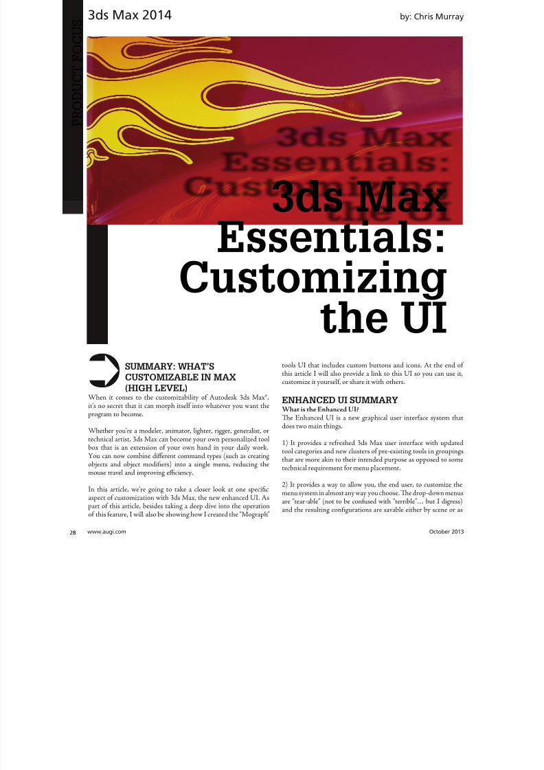
8122019 augi world 2013 10
httpslidepdfcomreaderfullaugi-world-2013-10 2952October 2013 wwwaugiworldcom
3ds Max 2014
a preset Tey are also distributable and deployable so they can beshared with others
Where is the Enhanced UITe Enhanced UI can be found in the upper left hand corner of themain UI at the very top of the screen Tere is a drop-down menuthat says ldquoWorkspace Defaultrdquo Tis default is the same baselineUI that ships with all 3ds Max installs (Figure 1)
Within the drop-down you can find the ldquoDefault with EnhancedMenusrdquo Tis is the alternative default menu system that youcan use on its own or use as a starting point to create your owncustomized menus
BASIC DEFAULT CUSTOMIZATIONEnhanced UI Customization BasicsNow that wersquove enabled the Enhanced UI how can we change it
SOP Before you begin mucking around with the UI Itrsquos importantto understand what I call the ldquosave-logicrdquo as it pertains to custom UIs
Te UI Save LogicIf you plan on saving this UI for future use there is a specificmethod you must follow to properly save the UI you want and notwreck the default Enhanced UI
Te Save Logic is as follows Itrsquos simple but important
Step 1 urn on Enhanced Default UI (Figure 3)
Step 2 Click ldquoSave as New Workspacerdquo FIRS At this point youwill be prompted for a new name (Figure 4)
Step 3 Edit and change the UI at will
NOE All future edits are ldquoautomatically rememberedrdquo as you go (Iintentionally did not use the word ldquosaverdquo)
Step 4 Te ldquosave as default staterdquo button is important When wehave completed the customization process we then choose thisbutton to ldquolockrdquo in the changes Tis is different than Saving a UIwith a custom name
HO IP ldquoBut this methodology seems backwardrdquo
I can see how yoursquod say that but remember that any changes you make
to any enhanced UI are automatically ldquorememberedrdquo If you create acustom UI then while working you make some temporary changeswhen doing something specific those little changes are automaticallyremembered If you want to return to the default state [of yourcustomized UI] you select ldquoReset to default staterdquo Tis does NObring back the default Max UI rather it brings back the customizedUI you created in ldquolockedrdquo in Step 4
Okay now that you have the save logic down letrsquos begin customizing
1) If you havenrsquot done so already turn on the Default Enhanced UI
2) Go to ldquoManage workspacesrdquo from the drop-down and in the
Figure 1 Workspaces are in the Workspace drop-down menu
Figure 2 Default UI (left) and the Default Enhanced UI (right)
Figure 4 Saving the New UI Workspace
Figure 3 Turning on the Enhanced Default UI
8122019 augi world 2013 10
httpslidepdfcomreaderfullaugi-world-2013-10 3052wwwaugicom October 20
3ds Max 2014
PRO
DUCT
FOCUS
Manage workspaces dialog choose ldquoSave as new Workspacerdquo Giveit a specific name
3) Begin making your desired changes
Since a custom UI is specific to any one individual letrsquos take a lookat what types of customizations can be made
Simple ChangesOne of the simplest things to do is peel off any commandgroup (see Figure 5) Just click the group title bar and drag Tecommand group becomes a floating dialog box Now just becauseyoursquove peeled it off does not mean that yoursquove removed it fromthe drop-down menu Te ldquooriginalrdquo command group remains inthe drop-down You can just close the floating dialog when yoursquoredone with it
Probably the simplest thing you can do is reorganize the menusIn each drop-down menu appears a group of commands You maynotice that some command groups are icons and some are words(Figure 6) o change the appearance of the commands there is asmall icon in the upper right corner of each group of commands(Figure 7)
Te next change is alreally simple Is tcommand group op(expanded) or clos(rolled up) Just clion the plus or minsign in the upper le
corner to set this stafor the next time yolaunch 3ds Max (Figu8) Remember thesettings are saved as yogo so whether it is opor closed is your choicbut the state the menis in when you cloMax is the one that remembered the netime Max opens
What about Saving tDefault state More othis later
Once you have floating menu yocan combine differecommand groups dragging any othcommand group to aother floating dial
that yoursquove created Tis makes for easy creation of custom dialo
based on specific tasks Figure 9 shows a command group fcharacter animationFigure 5 A floating menu that has been torn off the drop-downmenu
Figure 6 The different display states of the menus
Figure 7 Changing menu layouts
Figure 8 Rollouts
8122019 augi world 2013 10
httpslidepdfcomreaderfullaugi-world-2013-10 3152October 2013 wwwaugiworldcom
3ds Max 2014
ADVANCED CUSTOMIZATION
What about completely custom interfaces Herersquos how we do thatwith the Enhanced UI menu system
Te following is the high-level overview of the process Wersquoll thenunpack each step in more detail
If you havenrsquot read the section on Basic default customizationplease do so before continuing Before starting this phase ofcreating your new UI you should have saved your new UI stateTat process is explained in the previous section
1) Create a main drop-down menu (like ldquoMy oolsrdquo)
2) Create a tools category menu into which you will place yourtools (a submenu such as ldquoModeling oolsrdquo or ldquoAnimation oolsrdquo)Drop-downs can have more than one subcategory
3) Add commands to various submenus
4) Clean up the UI by creating custom names adding separatorsor creating custom icons
First letrsquos create a new menu for the menu bar Tis is done easilyfrom the CustomizegtCustomize [Rollout]gtCustomize UserInterface dialog box
Steps for Creating a Drop-Down Menu1) Create a New Menu and give it a name (see Figure 10)
2) Locate your new menu in the Menus window It will be listedalphabetically (Figure 11)
Figure 9 Multiple command groups in one menu
Figure 10 ndash Creating a new drop down menu
Figure 11 Location of new menu
8122019 augi world 2013 10
httpslidepdfcomreaderfullaugi-world-2013-10 3252wwwaugicom October 20
3ds Max 2014
PRO
DUCT
FOCUS
3) Drag your newly created menu category over to the column onthe right Tis will add your new drop-down menu to the interfaceimmediately and you can begin populating it with menu items (seeFigure 12)
UI DESIGN IP Te actual menu name and display name can bedifferent I used a custom menu name behind the scenes so I couldeasily differentiate my menus from the ones created by default or other
tool companies After you create a menu and add it to the right column you can right-click on it and change its display name (see Figure 13)
Next letrsquos create a command group1) Just like in Step 1 from the previous section create a new men
2) Tis time before you drag it to the right column click thplus sign next to your drop-down menu item to expand it Tedrag the new item to the right column dropping it ldquounderrdquo thmenu name
3) Drag any commands from the Commands window on the leto the submenu on the right (see Figure 15)
Herersquos an example from my Mograph ools workspace thshows how a completed menu looks once it is created (Figu16) In the following figure you see both the menu as it appeain the Customize UI dialog and the actual menu (which has bepeeled off)
Notice that some of the commands on the menu are greyed ouTatrsquos because this new menu combines both ldquoObject creatcommands and ldquoObject Modify Commandsrdquo in one menTey will remain grey until you create an object on which thwill be used
Figure 12 Adding the new menu to the UI
Figure 14 Creating a command group
Figure 15 Dragging commands onto the menu
Figure 13 Custom menu names
8122019 augi world 2013 10
httpslidepdfcomreaderfullaugi-world-2013-10 3352October 2013 wwwaugiworldcom
3ds Max 2014
Adding SeparatorsSeparating commands is easy and is recommended to help you oryour intended user make sense of the how the tools are arranged inthe menu Creating a separator is as easy as dragging one over theright column just like a menu or command
HO IP ldquoWhy do I need to create another menu Why canrsquot I addtools right to my menurdquo
Te main reason is that adding a submenu gives you the ability to tearoff the submenu If it werenrsquot in a submenu it wouldnrsquot be tear-ableSo itrsquos really a ldquobest practicesrdquo kind of thing But even if you try to notadd the submenu it will happen automatically Itrsquos important to do it
explicitly so you are aware of what submenus are in the menu and that you are the one in control of what command is going where
CUSTOM ICONSNo custom UI is complete without a custom set of iconsAdditionally not all commands in 3ds Max have their own iconyet But itrsquos important to realize that regardless of how you set up
your UI yoursquore still working within the framework of an existingapplication and there are boundaries to what you can edit andcreate Icons have specific requirements both in their creation(size) location and file name that must be adhered to in order forthem to work properly
SizeformatTe size of icon is pretty simple It must be 32x32 pixels andPNG format
LocationTe location is very specific New icons must be added to thislocation
CProgram FilesAutodesk3ds Max 2014UI_lnResourcesDarkIconsMain
Te new icons I created for the Mograph UI are shown inFigure 17)
Icon File NameIf yoursquore still with me at this point we are now getting into thenether regions of customizing a UI Tis is where things get a littletricky but itrsquos really not too bad File names are specific and aregenerated by the application (3ds Max)
So letrsquos begin First identify the command for which you want aniconmdashusually itrsquos one that doesnrsquot already have an icon But if itdoes and yoursquore changing it MAKE A BACK UP of the originalicon PNG file Tis is because as previously stated you donrsquot havecontrol over the file name Tat means if yoursquore creating your ownicon you need to overwrite the existing one and use its name foryour new icon So back up any original icons
Figure 16 The completed menu
Figure 17 ndash The created icons
8122019 augi world 2013 10
httpslidepdfcomreaderfullaugi-world-2013-10 3452wwwaugicom October 20
3ds Max 2014
PRO
DUCT
FOCUS
It really doesnrsquot matter whether you make the icon first or not ofind the name you need to use you need to navigate as follows
NOE Yoursquore about to edit the ribbon Tere is no need to save thesechanges as we are merely extracting information from it But if yoursquoredoing a lot of custom icon work you may want to save this change to theribbon so you can come back and continue your work in later sessionswithout have to recreate this every time just to get the proper file nameSaving this ribbon is not related to saving your default state of yourUI When yoursquore done creating all your UI icons you can just delete
whatever changes you make to the ribbon
1) Open the ldquoCustomize Ribbonrdquo dialog box
2) Create a new ldquotabrdquo by dragging it onto the ldquoExisting Ucolumn in the middle (see Figure 18)
3) Using the same drag method add a new ldquopanelrdquo to ttemp tab (Figure 19)
4) Now you can get the information you need Find tcommand for which you are creating an icon and dragto the panel
5) Locate the ldquoinfordquo portion of the ldquoPreview Windocolumn At the bottom of the column is the file namneeded to have the icon used properly by the applicati(Figure 20)
CONCLUSIONSo now you know how to create a custom UI scheme f3ds Max 2014 and up By using the Enhanced UI me
system itrsquos really easy to generate a multitude of workspathat allow Max to work the way you want to work
Te example used in this article was the ldquoMographrdquo UI thI created for NAB 2013 If you would like to downloand install it you can get it from my ldquoPinning the Stacblog on the Area herehttpareaautodeskcomblogschrismurray
Enjoy
Chris Murray works for Autodesk
Media amp Entertainment He istrained as an animator (3D variety)but considers himself a creative tech-nologist His daily role is a technicalldquoevangelistrdquo for Autodesk creating marketing deliverables for 3ds Max Heis the author of Mastering 3D StudioMax He has a Masters in Fine Arts(MFA) in Computer Animation fromMiami International University of Artand Design Follow him on witterchrismmurray
Figure 18 Creating a tab on the ribbon
Figure 19 Adding a panel to the tab
Figure 20 Finding the required file name
8122019 augi world 2013 10
httpslidepdfcomreaderfullaugi-world-2013-10 3552
AUGIMembersReach Higherwith ExpandedBenefitsAUGI is introducing three new Membership levelsthat will bring you more benefits than ever beforeEach level will bring you more content and expertiseto share with fellow members plus provide anexpanded more interactive website publicationaccess and much more
MEMBERMEMBER MEMBER
Basic members haveaccess tobull Forums
bullHotNews (last 12 months)
bull AUGIWorld (last 12 months)
DUES Free
Premier members haveaccess tobull Forums
bullHotNews (last 24 months)
bull AUGIWorld (last 24 months)
DUES $25
Professional members haveaccess tobull Forums
bullHotNews (full access)
bull AUGIWorld (full access and in print)
bull ADN 2013 Standard Membership Offer
DUES $100
Are you ready to upgrade yourself and your membership
Access additional benefits and upgrade at wwwaugicom
8122019 augi world 2013 10
httpslidepdfcomreaderfullaugi-world-2013-10 3652wwwaugicom October 20
AutoCAD MEP 2013
PRO
DUCT
FOCUS
by Vladimir Triantafillid
BIM IsWhatrsquos
Driving theIndustry
For the past decade many would arguethat building information modeling(BIM) has metastasized aggressivelythroughout the AEC industry but what
does BIM really mean More importantly whatdoes it do for us and for our industry Ask someone who hasbeen in this industry for more than 25 years or those nearingretirement and yoursquoll find that less than half see its value muchless care to make the effort with its implementation hesequestions mean something different for those who have beenin the industry the past 10-15 years Recent college graduates
however with their tech-savvy capacity and high expectationare eager to implement anything that resembles cutting-edgflashy technology ypical ly they are the ones most receptivenot adamant about putting their talents to use through BIM
I recently gave a BIM presentation with an emphasis on mchanical systems to the summer interns and new hires our companymdashall were non-BIM users except for onemdashbmy presentation did little justice to BIM Half of my audence had found a cure for their insomnia when they realizthis wasnrsquot the latest edition of ldquoCall of Dutyrdquo hat was n
8122019 augi world 2013 10
httpslidepdfcomreaderfullaugi-world-2013-10 3752October 2013 wwwaugiworldcom
AutoCAD MEP 2013
reflection on BIM by any measure Simply put I fell shortof connecting with a potentially captive audience eager toknow what really makes BIM intriguing or how it wouldgive them an edge in the industry I didnrsquot think to look pastpresenting the facts of its processes and benefits o simplyhave stated that proficiency in any of its many facets willpromote a lucrative career would give those still awake theimpetus to jump ship In hindsight the first step I shouldhave taken to begin this presentation was to ask what theywanted to get out of BIM
If you think itrsquos hard conveying the value and splendor ofBIM to receptive and impressionable young minds try toconvince the weathered veterans dead-set in their ldquooldtricksrdquo For every experienced veteran who has converted toBIM there are two ldquoold dogsrdquo that canrsquot shake ldquothe good olrsquodays when we used vellum and light tablesrdquo Guess whatmdashanincreasing amount of naysayers are starting to come aroundincluding those who say theyrsquove been burned by BIM in thepast hey are seeing the simple solutions BIM presents and
how these solutions translate into cost savings More andmore of those who had formerly questioned BIMrsquos utility areconvinced when installation efficiencies are not only real-ized but quantified
Another factor in the evolution of BIM is its tendency toexpand faster than the pace of its general population of us-ers hose of us proud to be catching up to what we think iscutting edge quickly realize it was just another false sense ofaccomplishment as BIMrsquos web continues to grow exponen-tially he solution is rather simple Focus on what you canhandle and always have the presence of mind and sense ofcaution to avoid being overwhelmed by the wake of BIMrsquos
progress herersquos plenty of money to be made and countlessfacets to explore as long we have the following mentality Welive in the information age and those wi lling to share knowl-edge will reap the rewards of communal synergy
On the opposite end of the spectrum you might find ourindustryrsquos opportunists In a hurried frenzy to claim theirspot in the intellectual property queue these opportunistsget carried away with pioneering what they assume is the lat-est improvements to BIM Instead of stopping to absorb anddevelop the benefits of 4D 5D 6D and so on the pioneersare spreading these ldquoDsrdquo thin with abandon further expand-
ing the gap between quality and quantity None of this i s tosay that wersquore heading in the wrong direction On the con-trary letrsquos call it more of a positive economic problemmdashthedemand for BIM expertise and development outweighs thesupply of available users
Fortunately as collegiate curricula catch on to this industrytrend the point of equilibrium will soon follow For as longas I can remember respective companiesrsquo 2D CAD depart-ments have been a significant source as the breeding groundfor potential BIM users While this route hasnrsquot changedregarding the career path of a draftsperson the source poolhas expanded to include architects engineers and construc-
tion managers just to name a few Itrsquos even hard not to noticeits stark demand when BIM and Revit courses are being in-creasingly offered at local community colleges I knew thenthat you didnrsquot necessarily need an undergraduate degreeback when I got my foot in the door of this industry hisprobably wonrsquot hold true in the coming years Still the privi-leged few who are already a part of this industry subset canrely on their experience in this fast-paced market to con-tinue to propel their careers forward ever faster All thesefew need to do is grab onto a small piece of BIMrsquos wing andhang on tight for the ride he fresh-out-of-college e ntrantsmight have a harder time grabbing onto this wing thatrsquos al-ready in motion
o those who are only vaguely famili ar with BIM it is typi-cally perceived as the equivalent of a 3D role-playing videogame In this case itrsquos not difficult to capture a ldquosnapshotrdquoimage of a 3D model shadows cast across random metal ob-
jects taking up space in an orderly fashion between ceil ingspaces and walls What is difficult is conveying the abun-dance of value behind the pretty picture to a client whorsquosonly interested in the pretty picture Who isnrsquot familiar withthe adage ldquoa picture is worth a thousand wordsrdquo Why notchange that saying to ldquoa BIM model is worth five thousandhyperlinksrdquo Now wersquore talking lifec ycles and facilities man-
More and moreof those who had
formerly questioned
BIMrsquos utilityare convinced
when installationefficiencies are notonly realized but
quantified
8122019 augi world 2013 10
httpslidepdfcomreaderfullaugi-world-2013-10 3852wwwaugicom October 20
AutoCAD MEP 2013
PRO
DUCT
FOCUS
agement his supposed video game has suddenly becomean encyclopedia of usable information But wait itrsquos not juststatic information thatrsquos stuck on a DVD on a shelf i n someownerrsquos random storage closet It has now become a livingdynamic source of real-time data Maintenance technicianswill know exactly where to go when the active 3D modelloaded on their laptop highlights a hot water pump needingservice while concurrently bringing up the cut sheets andoperation and maintenance manuals specific to that pumpor system Better still the source of information has shiftedfrom multiple stacks of large drawing sets collecting dust toseveral hundred gigabytes on a hard drive Yes Mrs Clientyour 3D BIM model will be usable for the next 20+ years
Even though you might not necessarily think about i t someof you probably realize that BIM has become the ldquomiddle-manrdquo for so many key components in the construction cyclewell beyond its intermediary role between design and con-struction phases You want to do some significant tenantimprovement in an existing building Laser-scan the exist-ing conditions hatrsquos BIM Is the general contractor rackingtheir brain trying to f igure out where to station the crane forthe project or pave the pathways for delivery trucks Nowtheyrsquore looking to BIM to answer these questions and opti-mize their decisions o take it a step further at which endof the building do we want to load thousands and thousands
of pounds of sheet metal and pipe And then which tradesshould be installing their systems first in any given area ofthe building hatrsquos right wersquore deriving sequencing andtimelines from the BIM model to e stablish the best routes totake while addressing any constructability issues BIM hasbecome the consultant that wears most of the hats Itrsquos ourone-stop shop
I know that Irsquove personified BIM as if itrsquos the brains behindall of its success Letrsquos take a moment to focus instead on itscollaborators or the sum of its integral parts to show thatin reality we are Dr Frankenstein and BIM is our monster
Except in our ca se wersquore beginning to ta me our monster anthose who were previously frightened by it are starting to sthat it indeed is no monster In fact while evolving to domdashand becomemdashgreater things BIM is transforming into aindustry hero he point of convergence is approaching bcause wersquore saving money time and even trees Soon enougBIM will be the industry standard even on the smaller proects Letrsquos keep the pedal to the meta l
You want to know the best news Most of us havenrsquot evebegun to scratch the surface of BIM but wersquore in strategpositions to reap the rewards aking the possibility of ivast potential into account isnrsquot it reassuring knowing th
in these tough economic times wersquore engaged in an industthat has a shortage of well-qualified BIM experts Our eposure alone sets us up for success Now ask yourselves thquestion Is BIM driving our industry or is it the BIM use
Vladimir riantafillidis works for aleading mechanical contractor in theSan Francisco Bay Area with morethan 10 years of experience in the in-dustry Although he has a bachelorrsquosdegree in biology his unique careerchoices have firmly rooted him in a
substantial BIM role awarding himthe opportunity of progressing along-side the relentless evolution of BIMOutside of his career hersquos always opento new adventures whether trying anew cuisine exotic travels or extremesports Te latter adventures have re-cently subsided as the balance of lifehas shifted his focus on spending timewith his growing family
You want to know the best news Most of us havenrsquot
even begun to scratch the surface of BIM but wersquore
in strategic positions to reap the rewards
8122019 augi world 2013 10
httpslidepdfcomreaderfullaugi-world-2013-10 3952
8122019 augi world 2013 10
httpslidepdfcomreaderfullaugi-world-2013-10 4052wwwaugicom October 20
Revit Structure 2014
PRO
DUCT
FOCUS
Streamlining
Sheet Listswith a Custom
Application
In this article we take a brief look a simpleadd-in for Autodeskreg Revitreg named X-Sheetswhich provides tools for incorporating sheetsfrom an AutoCADreg sheet set in a Revit sheet
list ypically this is handled by manually addingplaceholder sheets to the Revit sheet list Tis can be problematicbecause the sheet list becomes disconnected from the sourceand must be updated manually With X-Sheets sheet set datais exported directly from AutoCAD linked to a Revit project
and included in the sheet list by automatically addingupdatinplaceholder sheets For this example all structural scheduleplans elevations and section sheets are in Revit Structure Adetail sheets will be pulled from an external AutoCAD sheet set
X-SHEETS RIBBON PANEL Te first command on our ribbon panel is Discipline Tcommand is used to establish the Revit project parameter twhich the AutoCAD sheet subsets will be mapped For th
by Jonathan Albe
Figure 1 Revit X-Sheets ribbon panel
8122019 augi world 2013 10
httpslidepdfcomreaderfullaugi-world-2013-10 4152October 2013 wwwaugiworldcom
Revit Structure 2014
example we have created a project parameter named My DisciplineParameter Each Revit Structural sheet has been assigned a valueof SRUCURALmdashthe same as the subset name for theAutoCAD detail sheets Te sheet list is grouped and sorted bythis parameter
Te next command on the ribbon panel is Links Tis command isused to establish a link between the Revit project and XML file(s)
containing sheet information exported from AutoCAD You cancreate as many links as needed and use relative paths if required
Te next two commands Sheets and Update do the work ofaddingupdating placeholder sheets to the sheet list While theSheets command allows you to select individual sheets from linksto include in the sheet list the Update command includes all sheetsfrom all links
EXPORT SHEETS FROM AUTOCADFigure 3 shows the AutoCAD X-Sheets ribbon panel and asample sheet set containing structural detail sheets Notice thedetail sheets are grouped under a subset named SRUCURALTis subset name can be exported with each sheet and mapped to
the My Discipline Parameter in Revit Figure 3 shows the ExportSheets dialog with an option to include subset information and theability to exclude individual sheets Selecting the Export buttonprompts us with a dialog to save an XML file to be linked into ourRevit project
Figure 2 Discipline command dialog
Figure 3 AutoCAD X-Sheets ribbon panel and sample sheet set
Figure 4 Export sheets dialog
Figure 5 Export complete
8122019 augi world 2013 10
httpslidepdfcomreaderfullaugi-world-2013-10 4252wwwaugicom October 20
Revit Structure 2014
PRO
DUCT
FOCUS
ESTABLISH LINK TO XML FILE IN REVIT
PROJECTFigure 6 shows the Manage Links dialog A link has been added tothe XML file we generated when exporting sheets from AutoCADNotice there is an option to make the link path relative to our
Revit Project location
IMPORT SHEETS FROM XML LINKFigure 7 shows the Revit Structure sheet list before any sheetshave been imported from AutoCAD After selecting the Sheetscommand we are prompted with a Manage Sheets dialog
For this example we have selected all sheets from the XML linto include in our sheet list After confirming the dialog neplaceholder sheets are immediately added to the sheet list angrouped according to the SubsetDiscipline mapping Te neplaceholder sheets are identified behind the scenes as being relatto the X-Sheets XML link for later updating
Figure 6 Manage Links dialog
Figure 9 Sheet list after import
Figure 7 Sheet list before import
Figure 8 Manage Sheets dialog
The X-Sheets
add-in is a great tool
for incorporating
AutoCAD sheets into
a Revit sheet list
8122019 augi world 2013 10
httpslidepdfcomreaderfullaugi-world-2013-10 4352October 2013 wwwaugiworldcom
Revit Structure 2014
UPDATE SHEETSFigure 10 shows the Export Sheets dialog in AutoCAD afterdetail sheets have been renumbered to include ldquo-Ardquo When changesare made to AutoCAD sheets the original export steps must befollowed to replace the XML file linked to our Revit project Oncethe XML has been replaced simply run the Update command inRevit to update the sheet list
SUMMARYTe X-Sheets add-in is a great tool for incorporating AutoCADsheets into a Revit sheet list Te add-in saves time by automatically
adding placeholder sheets eliminates room for error in manualtranslation and helps to keep your sheet list up to date withminimal effort
Jonathan Albert is co-founder of BIM- pulse echnologies LLC amp SeniorApplications Developer at LindemanBentzon Bojack Engineering in Cler-mont Florida He has worked morethan 15 years implementing and usingBIM echnology for some of the na-tionrsquos leading production home build-
ers Most recently he has developedBIMpulse an Options Managementand Material akeoff Add-In for Au-toCAD Architecture Revit and Au-todesk Design Review Jonathan can bereached at jonalbbecom
Figure 10 Export Sheets dialog after sheet renumber
Figure 11 Update complete
Figure 12 Sheet list after update
The X-Sheets
add-in is agreat tool for
incorporatingAutoCAD
sheets intoa Revit
sheet list
8122019 augi world 2013 10
httpslidepdfcomreaderfullaugi-world-2013-10 4452wwwaugicom October 20
AutoCAD Civil 3D 2014
PRO
DUCT
FOCUS
by Tench Tilghma
Itrsquos a fact Jack You invested money in the worldrsquosmost popular civil engineering and designsoftware You (or someone else) will have workhard to make the software run productively
and publish the engineering design or surveywork acceptably
Every AutoCADreg Civil 3Dreg user will tell you ldquoYou need a Civil3D templaterdquo
heyrsquore right sort of You need more than one he suppliedexample Autodesk template files (dwt) are just thatmdashexamplesto show you that things are possible A great many ldquothingsrdquo arepossible in Civil 3D It is data-centric model-based software Asa dedicated content developer and continuous customizer of Civil3D I hope the following perspectives and tips help shorten thecycles and reduce the pain of customizing the software
AutoCAD Civil 3D was constructed from the ground up todisconnect the survey and engineering data from how that missioncritical data is represented
WITH LIBERTY COMES RESPONSIBILITYAs far as Autodesk is concerned what you want the many Civil 3Dldquothingsrdquo to look like and how the Civil 3D data is to be annotated istotally up to you hatrsquos not really true is it Plan sets are publishedin arcane symbolic graphic languages designed to faithfully conveythe design intent to someone who must build it with a plan checkeror two (or three or four) stuck in between
As a professional I prefer to call them ldquoPlan Set Languagesrdquo hhelps focus the development to the publishing of Civil 3D datMost people throw a fuzzy word around this complex mix human perceptive agendas and call that ldquoCAD Standardsrdquo
ldquohe wonderful thing about standards is there are so many of themndash Grace Hopper et al
PICK A STANDARD AND MANAGE BY ITldquoWe already have a CAD standardrdquo his may be the first anworst Civil 3D customization mistake any skilled AutoCAD usor organization can make he odds are the CAD standards yoemployed before do not take into account the data centric anmodel-based methods that Civil 3D employs Simply put Civ3D manages how things look and behave by Style Primitive-basAutoCADreg standards may get in the way
Older ldquoCADrdquo standards by definition must be focused on CAprimitive publishing specifics layer textstyle (height) blo
CustomizeCorrectly
Figure 1 Standards documentation is required
8122019 augi world 2013 10
httpslidepdfcomreaderfullaugi-world-2013-10 4552October 2013 wwwaugiworldcom
AutoCAD Civil 3D 2014
graphics standards and so on In raw AutoCAD and AutoCAD-based drafting and design software the only way to manage all theCAD primitive stuff was to be SPECIFIC about all the details allthe time he drawing we create and check things in is the drawingwe publish
If you publish work out of quality control or design drawingsin Civil 3D this is a sign you may be missing some of its timesaving advantages
While the old CADD process works it requires a lot of man-hoursdedicated to maintaining and checking the details Clearly one ofCivil 3Drsquos critical design development goals is to rid organizationsand Civil 3D users of this expensive man-hour burden and costhe idea here is to put the man-hours into the iterative engineeringprocess instead Civil 3D Feature data and Style make this possible
Civil 3D styles and label styles do employ the AutoCAD layertextstyle block references AutoCAD customizers are used tohe software is still called ldquoAutoCADrdquo Civil 3D after all Our
AutoCAD customization skills still apply But we must applythem differently and much more systematically Herersquos whyhellip
YOU NAME ITmdashTHE MOST CRITICAL
STANDARDCivil 3D Styles and label styles employ (reference) the AutoCADldquonamedrdquo parts to ldquoexpressrdquo themselves Style tools just look for andmatch the ldquorightrdquo names Change the ldquomeaningrdquo andor definitionof the names and you can change anything
We call this fundamental property and benefit of object-orientedprogramming the Power of Names In programming speak this
concept and practical reality is called a ldquonamespacerdquo
Such a namespace in engineering speak answers the questionldquoIn this context does ldquoDIrdquo means a ldquodrop inletrdquo In a minute wersquollget to the structure of a customization ldquonamespacerdquo for Civil 3DAutoCAD references
THE POWER OF NAMESGo ahead and make a drawing from your current Civil 3D templateoss in some Civil 3D data by data reference from any projectUse the RENAME command on any of the old AutoCAD stylecollectionsmdashtry layers
Rename like crazy Your existing Civil 3D styles and label styles willhappily work exactly the same he components in the Civil3DFeature and Label Styles will go to your renamed layers Becauseyou didnrsquot change the properties of the layers either nothingchanges Itrsquos not too exciting until you think about what it means
FOLLOW A SCRIPTObviously as customizers we never want to do this sort of workmanually Computers are faster better and more exact typists thanwe are We commonly rely on AutoCAD scripts generated from
Microsoft Excel spreadsheets (See the end of the article)
here are a couple of key collections in the object model thatCivil 3D walls off from this form of potentially destructiveuser madnessmdashObject Properties in Drawing Settings and afew things like Figure Prefix Dbs values that are not ever in thedrawing per se
WHAT REALLY MATTERSAutoCAD Civil 3D style is mind-boggling abstraction Everythingis designed and built to point at references We can employ styleabstraction for our benefit
In one sense AutoCAD Civil 3D style doesnrsquot care aboutAutoCAD layer standards block libraries textstyles colorsplotstyles or really anything else AutoCAD From our perspectiveall the Civil 3D styles care about are the arbitrary and exact namesthey currently reference
he Civil 3D customizerrsquos dilemma Keep book on the exactnames here are a lot of names to keep track of You must havea plan You must have rules You must employ the same processesconsistently in the same order to get quality assured results
Figure 2 Are description keys a namespace
Figure 3 Rename the AutoCAD reference names
8122019 augi world 2013 10
httpslidepdfcomreaderfullaugi-world-2013-10 4652wwwaugicom October 20
AutoCAD Civil 3D 2014
PRO
DUCT
FOCUS
hat Current word is a wonderfully relative term forthe customizer
Build a set of styles extract them to another drawing rename andor redefine the references and quickly produce a different resulthe Current method makes it easy to propagate success andmistake It makes it repetitively tedious to make fixes
NO CAN STOPAs innovative content developers for Civil 3D we chose to employthe National CAD Standard (NCS) as our fundamental Namestandard Not because we like the NCS but because of all thehard-won experience expressed in these tested standards Inmany respects we employ the NCS UDS (Uniform DrawingStandards) etc in our Production Solution products becauseof the underlying How and Why for those standards and theirpractical published Rules
We want to build faster high-performance vehicles Why reinventthe wheel when we can improve on it
STANDARD KEYS TO NAMEShe NCS employs a hierarchical concept of Keys here areMajor Keys Minor Keys etc that have order precedence and aninterpreted meaning he NCS Layer standard employs the Key-based rules to produce defined meanings to Layers
You can in practice employ the same Layer Keys to be genericor granularly specific about where the published results go Allthe annotation can go to one layer or many different layers forexample Styles andor sets do the work
his KEY CODE structure produces a flexible and structuredldquonamespacerdquo we referred to earlier Itrsquos a namespace that both thesoftware can employ and is relatively easy for us dumb-bunnyhumans to learn to decode when we must Most of the time theusers donrsquot and shouldnrsquot care anyway
Figure 4 shows a few of the NCS ldquolikerdquo Keys we employ in ourproducts We employ them for both layer and block collectionsand even the structure of libraries hey may even be employedin Civil 3D style names when thatrsquos appropriate (See the endof the article)
he customizing key point is that the meanings of these specificKeys can be translated into any other set (or sets) of different
Keys he Key changes can be systematically applied to whatevAutoCAD reference tables and resources we require
he results of any changes will float uphill to the named Civil 3Styles we choose to employ hink of all the AutoCAD referencin a template as a Set
BEYOND AUTOCADNow wersquove looped back to Civil 3D style tools and substantivetheir names and what their parts refer to Welcome to the circuland iterative world that is customizing and employing Civil 3D
Aside from the requisite customization skills and experience build style tools our practical biggest customization issues afrankly Civil 3D human interface issues
No matter how you cut it you have a very limited amount of tespace to help users decide on the ldquorightrdquo style tool to use he teof the style toolrsquos name is all you get to deliver to the user ypicaitrsquos a pick box list
You might get lucky and have the Style Viewer but that Viewcannot represent everything a style can do
FEATURE STYLES NAMESWhat we call the ldquoFeature Stylesrdquo (the Ci3D Featurersquos graphics) require that our stynames explain in simple readable humterms what the tool does For examplesurface style like ldquoContours 1-5 Proposed
Figure 4 Some standard keys
Figure 5 The limitations of user style choice
8122019 augi world 2013 10
httpslidepdfcomreaderfullaugi-world-2013-10 4752October 2013 wwwaugiworldcom
AutoCAD Civil 3D 2014
For the common and most understood features this makes somesense ASCII order rules how named Styles organize Names mustsort that out
Complex graphic features such as Views have a lot more going onldquoMy Standard Profile Viewrdquo doesnrsquot cut it except in a publishingtemplate he style names must be more informative and specificDoes the Profile View include grid lines or not We must recognizethat the engineering data behind what we want to visualize isvariable and the user will have specific needs to get work doneWhen you check a surface you need to see the data in differentways than when the result is published
Choice of style is productive Choice is not contrary to publishingstandards unless you mix the two
LABEL STYLE NAME FACTORSWhen we open the Alignment Label Style collection andorstart to assemble Sets of Label Styles we see any hope of namesimplicity for label styles disappears in a flash
he majority of styles are annotative here are a lot of formsand specific types of them Label Style ype matters he smartcustomizer employs the Label Style Default (LSD) hierarchyexpressed in the oolspacegtgtSettings tab or ignores it and missesthe benefits
Label styles often must have a geometric framework to themItrsquos about ldquoreadabilityrdquo and meaning Whether this label goes upor down or attaches here and not there is critical to annotativeclarity he graphic structure of many data-rich label styles alsofundamentally matters to the stylersquos upgrade stability herersquos
a maintenance cost to pay if you refuse to employ consistentgeometric structures in label styles
CUSTOM USAGECan users see the right data and at the right time Will the useremploy a general alignment parcel or figure line and curve labelHow do they see the difference in a simple list It is easy to misshow ldquoon-the-flyrdquo annotative information negatively or positivelyeffects design time decision making and quality control Peoplewill make things to get the job done Do you fight it or enable ithe Simple Style Rules anyone can learn
THE CIVIL 3D NAMESPACESA Civil 3D style naming convention must be human readablecreate order in the interface and therefore include a rule-basedeasy-to-learn code system that expresses quickly the critical detailso customize we need two namespaces One for the top-end stylesand one for the back-end AutoCAD references In productionprojects we need a third namespace for how we name the featuresbut thatrsquos another story
his client and this project demand these CAD standards specificsAnother client and project demand something different Even ifyou donrsquot believe you regularly face that common problem you
still have to improve the internal production templates themselveshe method and process arenrsquot different
In our project-based production world Civil 3D users andsupervisory staff can always work with the familiar and publishwhat is demanded in a customized publishing template hetwo-pronged project template approach has the added benefit ofpotentially quantifying the costs and real return on investment forthe customization itself
CUSTOMIZE TO PUBLISH ON DEMANDIn practical terms we can change the expressed graphicsmdashthe PlanSet Language (CAD standards) with managed intern level staffEven non-CAD people can see and identify graphic differenceOnly basic AutoCAD and basic spreadsheets skills are requiredfor much of the work if you have a naming plan ldquoChange thatmanhole block to look like this manhole blockrdquo Your ldquothatrdquo mustbe specific
ldquoPublish on demandrdquo capability is a productivity and competitive
advantage but it takes repetitions to develop and practice the skillsWe must endlessly customize Civil 3Dmdashreap the benefits
CIVIL 3D NAME RESOURCEShe Standard Keys the NCS-like AutoCAD reference namespacehe Jump Standards includes the detailed and documented stylenamespace Find them at wwwcadpilotcomresourcesaspx
Excel Cell Formula Script ExampleHerersquos the pseudo code for a typical formula-based layer script thatmakes a layer table with all the details filled in from a cell It createsa series of quote wrapped strings when a column of such cells is
copied and pasted to an ASCII text file
ltLayerCommandgtampCHAR(13)amprdquoSrdquoampCHAR(13)ampltOldLayergtampCHAR(13)amprdquoRrdquoampCHAR(13)ampltNewLayergtampCHAR(13)ampltNewLayergtampCHAR(13)amprdquoCrdquoampCHAR(13)ampltColorgtampCHAR(13)ampCHAR(13)amprdquoLWrdquoampCHAR(13)ampltLineweightgtampCHAR(13)ampCHAR(13)amprdquoPSrdquoampCHAR(13)ampltPlotstylegtampCHAR(13)ampCHAR(13)amprdquoDrdquoampCHAR(13)ampltDescriptiongtampCHAR(13)ampltNewLayergtampCHAR(13)
ench ilghman is President ofMoreCompetency Inc an Autodesk
Developer Partner specializing in in-novative Civil 3D Production Solu-tion products and consulting services
for AutoCAD Civil 3D ench is aregular speaker at Autodesk Univer-sity and AEC industry events on thetopics of technology adoption innova-tion and (his personal favorite) peopleskills He posts on the Get the Jump onCivil 3D blog
8122019 augi world 2013 10
httpslidepdfcomreaderfullaugi-world-2013-10 4852wwwaugicom October 20
Revit MEP 2014
PRO
DUCT
FOCUS
by Todd Shackelfor
W
hen any new technology hits theground there are plenty of false startsand backtracking In time shortcutsare found tricks of the trade are
discovered and best practices are defined So is thecase with Autodeskreg Revitreg even for MEP users his article willoutline a logical roadmap of technical and non-technical mustdorsquos and donrsquot dorsquos for transitioning to Revit MEP From settingexpectations defining goals and plotting in Revit to addressingBIM IPD and VDC the checklist of elements required to helpRevit really work in an office will be covered Every implementationwill come with resistance workflow issues and plenty of headachesbut staying on course and hitting the important milestones alongthe way will help reduce stress of something akin to the craziestfamily trip ever
FIRST CONSIDERATIONS ndash SOFTWAREOne might think it is all about Revit he truth is that Revit reallywants to act as a central location for data that is constantly on themove Much like a smartphone leverages the power of thousandsof applications Revit plugs into workflows with more than a fewAutodesk programs as well as a host of third-party programs hesimple fact that the Building Design Suite comes with so manyvaried applications is a pretty big hint that Revit wants to play ona team Firms need to look at their processes from a high level andlook for the best workflows and programs for the team
FIRST CONSIDERATIONS ndash HARDWAREEvaluate the PCs and know what their capabilities are anknow what Revit requires Search Autodeskrsquos website for systerequirements for Revit products Requirements for three tieof deployment are listed for systems covering an entry-levconfiguration a balanced performance configuration and performance configuration Certified and supported graphi
hardware is also accessible from this page he non-hardwasavvy should seek input from an I professional Revit cannand will not perform on outdated or entry-level PCs and thperson leading the implementation usually takes the blame wheexpectations fall short Best advice is overkill it on hardware Whseems over the top today is inadequate in a year
FIRST CONSIDERATIONS ndash TRAININGhere is no way to get around the fact that training will need tbe done Even if every person in the firm has already used Revtraining on using Revit company standards must still take plachere are many ways to deliver training An in-house expe
TransitionRoadmap
8122019 augi world 2013 10
httpslidepdfcomreaderfullaugi-world-2013-10 4952October 2013 wwwaugiworldcom
Revit MEP 2014
can provide just-in-time all the time Autodesk resellers andconsultants typically provide three- to five-day immersion trainingand short- to long-term consulting here are countless web-based training optionsmdashfree and paid Community colleges thatoffer Revit training usually require a final project that will putstudents through the paces and better entrench the
knowledge and skills
On the down side Revit MEP-specific classes areall but impossible to find Lastly the extreme go-getter can buy a book and learn on the job In realityeveryone learns differently and being preparedto leverage all these types of training is the bestsolution People will gravitate to the solution thatworks best for them when it is provided
FIRST CONSIDERATIONS ndash
LINE UP YOUR DUCTS (UGH hellip
DUCKS)Set appropriate goals based on the size of thefirm Small medium and large firms will havedrastically different goals and timelines It mightseem odd but small firms have the upper hand inadopting new technologies and processes hinkabout it What is easiermdashgetting 3 people toagree or 300 Recognize that an AE firm will havecompletely different goals and processes than a solely MEP firmDuring any shift in process be prepared to support the old andnew at the same time and sometimes in the same project hiswill mean keeping symbols in Revit as close as possible to symbols
in AutoCADreg Consider how quality reviews are done and clientexpectations When things look different it is an impediment tochange Minimizing the impediments will help tremendously
All that being said communication is the real key to most everyprojectrsquos success It is important keep information flowing upand down the chain and set the expectations early Some criticalexpectations for this type of implementation are that things will gowrong things will take longer things will look different things willhave to change and things will continue to evolve Remind usersand management of the progress they have been made by trackingand documenting incremental goals
With a general direction and expectations set itrsquos time to get morespecific about the journey his trip is a long one and a phasedapproach is best Firms can tailor the following phasing to suitindividual needs his example has four phasesmdasheach with itsown goals building off the previous phases
Phase 1 - Goals1 Create construction documents2 Improved collaboration3 Interference mitigationo obtain these goals the following Revit items need to be addressedhe first group addresses the goal of good construction documentshe second group deals with process and keeping things standardhe space available in this article doesnrsquot allow for ldquoHow torsquosrdquo foreach item but each is well documented in the Revit help pageand all over the Internet Get a couple points of view and marrythe possibilities to the culture and needs of the firm in question
bull Line styles createdbull Fonts set for plan text titles title blocks tags and everything
elsebull Object styles ndash Define the weight color tone and transparency
of everything bull Incorporation of standard detailsbull Browser organization ndash Decide how you want to see views
organizedbull Filters ndash Know if you need standard filters and create them
ahead of timebull Phasesbull View templatesbull Project templatebull Duct Stylesbull Pipe stylesbull Family creation
Figure 1
Figure 2
8122019 augi world 2013 10
httpslidepdfcomreaderfullaugi-world-2013-10 5052
8122019 augi world 2013 10
httpslidepdfcomreaderfullaugi-world-2013-10 5152October 2013 wwwaugiworldcom
Inside Track
CSCrsquos Integratorhttpwwwcscworldcom
Integrator is a tool that allows you to synchronize structural designscreated in CSCrsquos Fastrak Building Designer (steel building designsoftware) and Orion (structural concrete building design software)with Autodeskreg Revitreg 2014
ldquoLeading structural software provider CSC has released a new versionof Integrator its market leading Structural BIM integration softwarefor synchronizing code-compliant models produced in CSCrsquos buildingdesign software Fastrak and Orion with Autodeskreg Revitreg Nowfully compatible with Autodesk Revit 2014 structural engineers andtechnicians have even greater control during the integration process
Using Integrator full and part models can be synchronized betweenFastrak or Orion and Autodesk Revit with the ability to manageadded deleted and modified members and their associated
design datardquo
BiMTOOLShttpwwwsofistikcom
BiMOOLS is a set of productivity tools that are designed forAutodeskreg Revitreg 2014 Te plug-in can be installed from theAutodesk Exchange Apps store
ldquoTe first international version of the SOFiSiK BiMOOLS isnow available SOFiSiK BiMOOLS is a collection of free tools forAutodeskreg Revitreg Structure to enhance the productivity up to 50Te features range from easy font type substitution and automaticgeneration of dimensional lines over the automatic positioning ofstructural elements to the comprehensive Family Creator to generatefamilies of eg beams braces and columns for optimal communicationwith FE analysis tools like the SOFiSiK softwarerdquo
Find further information and download links for Revit 2012 and
2013 on the dedicated BiMOOLS website
Autodesk AutoCAD 360 21httpswwwautocad360com
Autodeskreg AutoCADreg 360 is a mobile and web-based application that allows you to view editand share drawing files created with AutoCADand AutoCAD-based products Te mobile appis available from the Apple iunes App Store andGoogle Play Store
ldquoAutoCAD 360 is a free easy-to-use drawing and drafting mobileapp that allows you to view edit and share AutoCAD drawingsmdashanytime anywhere Simplify site visits and fieldwork with powerfuldesign review and markup toolsmdashavailable online and offline
Seamlessly share drawings with others across desktop web andmobile devices Easily access drawings from web browsers using
the free companion AutoCAD 360 web app AutoCAD 360Pro subscription plans further expand the functionality of
the app bringing additional capabilities to the fieldrdquo
Te updates that are in this latest release arebull Stunning high-resolution drawings display
via full retina supportbull Better display through improved PDF
supportbull Easy switching between metric and imperial
unitsbull Saves time with faster app loading bull Improved collaboration through in-app
notifications and streamlined sharing bull New properties for Properties Palette
(Pro version)
AUGIWorldbrings
you recentdevelopmentsin Autodeskand AEC-relatedsoftwareitems
Until next issue
If you have some news to share with us for future issues please let usknow Likewise if you are a user of a featured product or news itemand would like to write a review we want to know
By Lee Ambrosius
8122019 augi world 2013 10
httpslidepdfcomreaderfullaugi-world-2013-10 5252
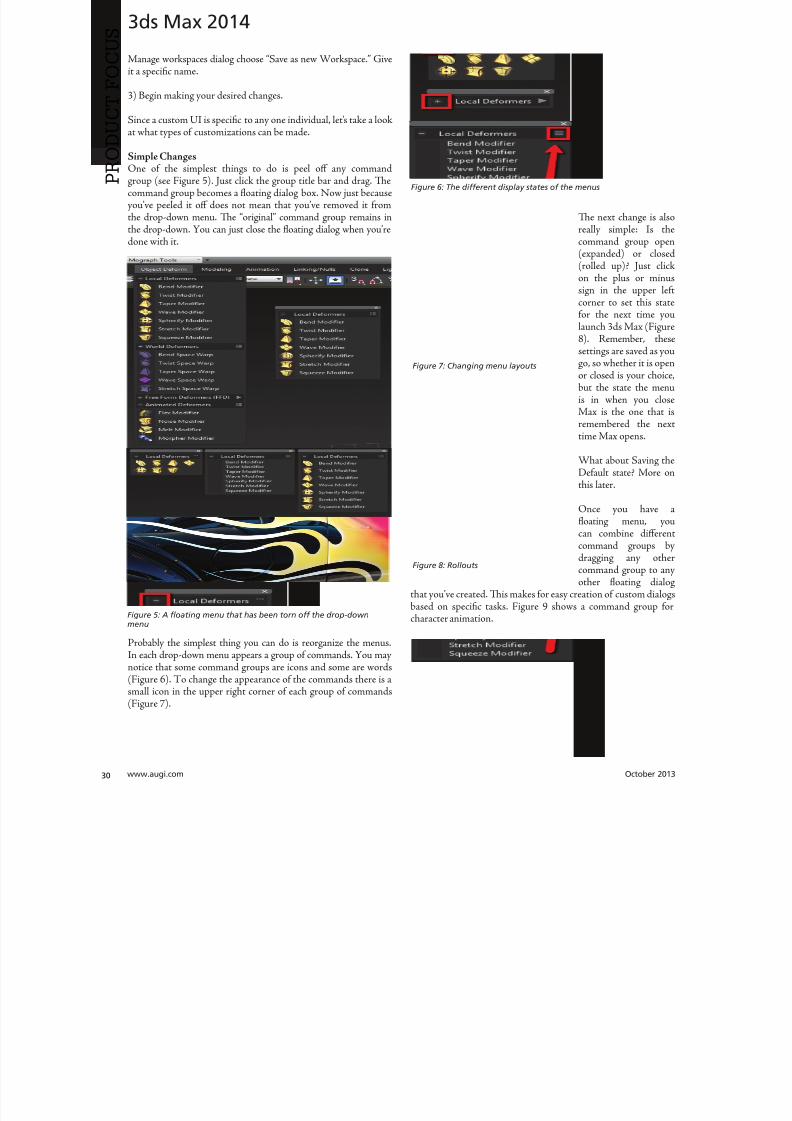
8122019 augi world 2013 10
httpslidepdfcomreaderfullaugi-world-2013-10 3052wwwaugicom October 20
3ds Max 2014
PRO
DUCT
FOCUS
Manage workspaces dialog choose ldquoSave as new Workspacerdquo Giveit a specific name
3) Begin making your desired changes
Since a custom UI is specific to any one individual letrsquos take a lookat what types of customizations can be made
Simple ChangesOne of the simplest things to do is peel off any commandgroup (see Figure 5) Just click the group title bar and drag Tecommand group becomes a floating dialog box Now just becauseyoursquove peeled it off does not mean that yoursquove removed it fromthe drop-down menu Te ldquooriginalrdquo command group remains inthe drop-down You can just close the floating dialog when yoursquoredone with it
Probably the simplest thing you can do is reorganize the menusIn each drop-down menu appears a group of commands You maynotice that some command groups are icons and some are words(Figure 6) o change the appearance of the commands there is asmall icon in the upper right corner of each group of commands(Figure 7)
Te next change is alreally simple Is tcommand group op(expanded) or clos(rolled up) Just clion the plus or minsign in the upper le
corner to set this stafor the next time yolaunch 3ds Max (Figu8) Remember thesettings are saved as yogo so whether it is opor closed is your choicbut the state the menis in when you cloMax is the one that remembered the netime Max opens
What about Saving tDefault state More othis later
Once you have floating menu yocan combine differecommand groups dragging any othcommand group to aother floating dial
that yoursquove created Tis makes for easy creation of custom dialo
based on specific tasks Figure 9 shows a command group fcharacter animationFigure 5 A floating menu that has been torn off the drop-downmenu
Figure 6 The different display states of the menus
Figure 7 Changing menu layouts
Figure 8 Rollouts
8122019 augi world 2013 10
httpslidepdfcomreaderfullaugi-world-2013-10 3152October 2013 wwwaugiworldcom
3ds Max 2014
ADVANCED CUSTOMIZATION
What about completely custom interfaces Herersquos how we do thatwith the Enhanced UI menu system
Te following is the high-level overview of the process Wersquoll thenunpack each step in more detail
If you havenrsquot read the section on Basic default customizationplease do so before continuing Before starting this phase ofcreating your new UI you should have saved your new UI stateTat process is explained in the previous section
1) Create a main drop-down menu (like ldquoMy oolsrdquo)
2) Create a tools category menu into which you will place yourtools (a submenu such as ldquoModeling oolsrdquo or ldquoAnimation oolsrdquo)Drop-downs can have more than one subcategory
3) Add commands to various submenus
4) Clean up the UI by creating custom names adding separatorsor creating custom icons
First letrsquos create a new menu for the menu bar Tis is done easilyfrom the CustomizegtCustomize [Rollout]gtCustomize UserInterface dialog box
Steps for Creating a Drop-Down Menu1) Create a New Menu and give it a name (see Figure 10)
2) Locate your new menu in the Menus window It will be listedalphabetically (Figure 11)
Figure 9 Multiple command groups in one menu
Figure 10 ndash Creating a new drop down menu
Figure 11 Location of new menu
8122019 augi world 2013 10
httpslidepdfcomreaderfullaugi-world-2013-10 3252wwwaugicom October 20
3ds Max 2014
PRO
DUCT
FOCUS
3) Drag your newly created menu category over to the column onthe right Tis will add your new drop-down menu to the interfaceimmediately and you can begin populating it with menu items (seeFigure 12)
UI DESIGN IP Te actual menu name and display name can bedifferent I used a custom menu name behind the scenes so I couldeasily differentiate my menus from the ones created by default or other
tool companies After you create a menu and add it to the right column you can right-click on it and change its display name (see Figure 13)
Next letrsquos create a command group1) Just like in Step 1 from the previous section create a new men
2) Tis time before you drag it to the right column click thplus sign next to your drop-down menu item to expand it Tedrag the new item to the right column dropping it ldquounderrdquo thmenu name
3) Drag any commands from the Commands window on the leto the submenu on the right (see Figure 15)
Herersquos an example from my Mograph ools workspace thshows how a completed menu looks once it is created (Figu16) In the following figure you see both the menu as it appeain the Customize UI dialog and the actual menu (which has bepeeled off)
Notice that some of the commands on the menu are greyed ouTatrsquos because this new menu combines both ldquoObject creatcommands and ldquoObject Modify Commandsrdquo in one menTey will remain grey until you create an object on which thwill be used
Figure 12 Adding the new menu to the UI
Figure 14 Creating a command group
Figure 15 Dragging commands onto the menu
Figure 13 Custom menu names
8122019 augi world 2013 10
httpslidepdfcomreaderfullaugi-world-2013-10 3352October 2013 wwwaugiworldcom
3ds Max 2014
Adding SeparatorsSeparating commands is easy and is recommended to help you oryour intended user make sense of the how the tools are arranged inthe menu Creating a separator is as easy as dragging one over theright column just like a menu or command
HO IP ldquoWhy do I need to create another menu Why canrsquot I addtools right to my menurdquo
Te main reason is that adding a submenu gives you the ability to tearoff the submenu If it werenrsquot in a submenu it wouldnrsquot be tear-ableSo itrsquos really a ldquobest practicesrdquo kind of thing But even if you try to notadd the submenu it will happen automatically Itrsquos important to do it
explicitly so you are aware of what submenus are in the menu and that you are the one in control of what command is going where
CUSTOM ICONSNo custom UI is complete without a custom set of iconsAdditionally not all commands in 3ds Max have their own iconyet But itrsquos important to realize that regardless of how you set up
your UI yoursquore still working within the framework of an existingapplication and there are boundaries to what you can edit andcreate Icons have specific requirements both in their creation(size) location and file name that must be adhered to in order forthem to work properly
SizeformatTe size of icon is pretty simple It must be 32x32 pixels andPNG format
LocationTe location is very specific New icons must be added to thislocation
CProgram FilesAutodesk3ds Max 2014UI_lnResourcesDarkIconsMain
Te new icons I created for the Mograph UI are shown inFigure 17)
Icon File NameIf yoursquore still with me at this point we are now getting into thenether regions of customizing a UI Tis is where things get a littletricky but itrsquos really not too bad File names are specific and aregenerated by the application (3ds Max)
So letrsquos begin First identify the command for which you want aniconmdashusually itrsquos one that doesnrsquot already have an icon But if itdoes and yoursquore changing it MAKE A BACK UP of the originalicon PNG file Tis is because as previously stated you donrsquot havecontrol over the file name Tat means if yoursquore creating your ownicon you need to overwrite the existing one and use its name foryour new icon So back up any original icons
Figure 16 The completed menu
Figure 17 ndash The created icons
8122019 augi world 2013 10
httpslidepdfcomreaderfullaugi-world-2013-10 3452wwwaugicom October 20
3ds Max 2014
PRO
DUCT
FOCUS
It really doesnrsquot matter whether you make the icon first or not ofind the name you need to use you need to navigate as follows
NOE Yoursquore about to edit the ribbon Tere is no need to save thesechanges as we are merely extracting information from it But if yoursquoredoing a lot of custom icon work you may want to save this change to theribbon so you can come back and continue your work in later sessionswithout have to recreate this every time just to get the proper file nameSaving this ribbon is not related to saving your default state of yourUI When yoursquore done creating all your UI icons you can just delete
whatever changes you make to the ribbon
1) Open the ldquoCustomize Ribbonrdquo dialog box
2) Create a new ldquotabrdquo by dragging it onto the ldquoExisting Ucolumn in the middle (see Figure 18)
3) Using the same drag method add a new ldquopanelrdquo to ttemp tab (Figure 19)
4) Now you can get the information you need Find tcommand for which you are creating an icon and dragto the panel
5) Locate the ldquoinfordquo portion of the ldquoPreview Windocolumn At the bottom of the column is the file namneeded to have the icon used properly by the applicati(Figure 20)
CONCLUSIONSo now you know how to create a custom UI scheme f3ds Max 2014 and up By using the Enhanced UI me
system itrsquos really easy to generate a multitude of workspathat allow Max to work the way you want to work
Te example used in this article was the ldquoMographrdquo UI thI created for NAB 2013 If you would like to downloand install it you can get it from my ldquoPinning the Stacblog on the Area herehttpareaautodeskcomblogschrismurray
Enjoy
Chris Murray works for Autodesk
Media amp Entertainment He istrained as an animator (3D variety)but considers himself a creative tech-nologist His daily role is a technicalldquoevangelistrdquo for Autodesk creating marketing deliverables for 3ds Max Heis the author of Mastering 3D StudioMax He has a Masters in Fine Arts(MFA) in Computer Animation fromMiami International University of Artand Design Follow him on witterchrismmurray
Figure 18 Creating a tab on the ribbon
Figure 19 Adding a panel to the tab
Figure 20 Finding the required file name
8122019 augi world 2013 10
httpslidepdfcomreaderfullaugi-world-2013-10 3552
AUGIMembersReach Higherwith ExpandedBenefitsAUGI is introducing three new Membership levelsthat will bring you more benefits than ever beforeEach level will bring you more content and expertiseto share with fellow members plus provide anexpanded more interactive website publicationaccess and much more
MEMBERMEMBER MEMBER
Basic members haveaccess tobull Forums
bullHotNews (last 12 months)
bull AUGIWorld (last 12 months)
DUES Free
Premier members haveaccess tobull Forums
bullHotNews (last 24 months)
bull AUGIWorld (last 24 months)
DUES $25
Professional members haveaccess tobull Forums
bullHotNews (full access)
bull AUGIWorld (full access and in print)
bull ADN 2013 Standard Membership Offer
DUES $100
Are you ready to upgrade yourself and your membership
Access additional benefits and upgrade at wwwaugicom
8122019 augi world 2013 10
httpslidepdfcomreaderfullaugi-world-2013-10 3652wwwaugicom October 20
AutoCAD MEP 2013
PRO
DUCT
FOCUS
by Vladimir Triantafillid
BIM IsWhatrsquos
Driving theIndustry
For the past decade many would arguethat building information modeling(BIM) has metastasized aggressivelythroughout the AEC industry but what
does BIM really mean More importantly whatdoes it do for us and for our industry Ask someone who hasbeen in this industry for more than 25 years or those nearingretirement and yoursquoll find that less than half see its value muchless care to make the effort with its implementation hesequestions mean something different for those who have beenin the industry the past 10-15 years Recent college graduates
however with their tech-savvy capacity and high expectationare eager to implement anything that resembles cutting-edgflashy technology ypical ly they are the ones most receptivenot adamant about putting their talents to use through BIM
I recently gave a BIM presentation with an emphasis on mchanical systems to the summer interns and new hires our companymdashall were non-BIM users except for onemdashbmy presentation did little justice to BIM Half of my audence had found a cure for their insomnia when they realizthis wasnrsquot the latest edition of ldquoCall of Dutyrdquo hat was n
8122019 augi world 2013 10
httpslidepdfcomreaderfullaugi-world-2013-10 3752October 2013 wwwaugiworldcom
AutoCAD MEP 2013
reflection on BIM by any measure Simply put I fell shortof connecting with a potentially captive audience eager toknow what really makes BIM intriguing or how it wouldgive them an edge in the industry I didnrsquot think to look pastpresenting the facts of its processes and benefits o simplyhave stated that proficiency in any of its many facets willpromote a lucrative career would give those still awake theimpetus to jump ship In hindsight the first step I shouldhave taken to begin this presentation was to ask what theywanted to get out of BIM
If you think itrsquos hard conveying the value and splendor ofBIM to receptive and impressionable young minds try toconvince the weathered veterans dead-set in their ldquooldtricksrdquo For every experienced veteran who has converted toBIM there are two ldquoold dogsrdquo that canrsquot shake ldquothe good olrsquodays when we used vellum and light tablesrdquo Guess whatmdashanincreasing amount of naysayers are starting to come aroundincluding those who say theyrsquove been burned by BIM in thepast hey are seeing the simple solutions BIM presents and
how these solutions translate into cost savings More andmore of those who had formerly questioned BIMrsquos utility areconvinced when installation efficiencies are not only real-ized but quantified
Another factor in the evolution of BIM is its tendency toexpand faster than the pace of its general population of us-ers hose of us proud to be catching up to what we think iscutting edge quickly realize it was just another false sense ofaccomplishment as BIMrsquos web continues to grow exponen-tially he solution is rather simple Focus on what you canhandle and always have the presence of mind and sense ofcaution to avoid being overwhelmed by the wake of BIMrsquos
progress herersquos plenty of money to be made and countlessfacets to explore as long we have the following mentality Welive in the information age and those wi lling to share knowl-edge will reap the rewards of communal synergy
On the opposite end of the spectrum you might find ourindustryrsquos opportunists In a hurried frenzy to claim theirspot in the intellectual property queue these opportunistsget carried away with pioneering what they assume is the lat-est improvements to BIM Instead of stopping to absorb anddevelop the benefits of 4D 5D 6D and so on the pioneersare spreading these ldquoDsrdquo thin with abandon further expand-
ing the gap between quality and quantity None of this i s tosay that wersquore heading in the wrong direction On the con-trary letrsquos call it more of a positive economic problemmdashthedemand for BIM expertise and development outweighs thesupply of available users
Fortunately as collegiate curricula catch on to this industrytrend the point of equilibrium will soon follow For as longas I can remember respective companiesrsquo 2D CAD depart-ments have been a significant source as the breeding groundfor potential BIM users While this route hasnrsquot changedregarding the career path of a draftsperson the source poolhas expanded to include architects engineers and construc-
tion managers just to name a few Itrsquos even hard not to noticeits stark demand when BIM and Revit courses are being in-creasingly offered at local community colleges I knew thenthat you didnrsquot necessarily need an undergraduate degreeback when I got my foot in the door of this industry hisprobably wonrsquot hold true in the coming years Still the privi-leged few who are already a part of this industry subset canrely on their experience in this fast-paced market to con-tinue to propel their careers forward ever faster All thesefew need to do is grab onto a small piece of BIMrsquos wing andhang on tight for the ride he fresh-out-of-college e ntrantsmight have a harder time grabbing onto this wing thatrsquos al-ready in motion
o those who are only vaguely famili ar with BIM it is typi-cally perceived as the equivalent of a 3D role-playing videogame In this case itrsquos not difficult to capture a ldquosnapshotrdquoimage of a 3D model shadows cast across random metal ob-
jects taking up space in an orderly fashion between ceil ingspaces and walls What is difficult is conveying the abun-dance of value behind the pretty picture to a client whorsquosonly interested in the pretty picture Who isnrsquot familiar withthe adage ldquoa picture is worth a thousand wordsrdquo Why notchange that saying to ldquoa BIM model is worth five thousandhyperlinksrdquo Now wersquore talking lifec ycles and facilities man-
More and moreof those who had
formerly questioned
BIMrsquos utilityare convinced
when installationefficiencies are notonly realized but
quantified
8122019 augi world 2013 10
httpslidepdfcomreaderfullaugi-world-2013-10 3852wwwaugicom October 20
AutoCAD MEP 2013
PRO
DUCT
FOCUS
agement his supposed video game has suddenly becomean encyclopedia of usable information But wait itrsquos not juststatic information thatrsquos stuck on a DVD on a shelf i n someownerrsquos random storage closet It has now become a livingdynamic source of real-time data Maintenance technicianswill know exactly where to go when the active 3D modelloaded on their laptop highlights a hot water pump needingservice while concurrently bringing up the cut sheets andoperation and maintenance manuals specific to that pumpor system Better still the source of information has shiftedfrom multiple stacks of large drawing sets collecting dust toseveral hundred gigabytes on a hard drive Yes Mrs Clientyour 3D BIM model will be usable for the next 20+ years
Even though you might not necessarily think about i t someof you probably realize that BIM has become the ldquomiddle-manrdquo for so many key components in the construction cyclewell beyond its intermediary role between design and con-struction phases You want to do some significant tenantimprovement in an existing building Laser-scan the exist-ing conditions hatrsquos BIM Is the general contractor rackingtheir brain trying to f igure out where to station the crane forthe project or pave the pathways for delivery trucks Nowtheyrsquore looking to BIM to answer these questions and opti-mize their decisions o take it a step further at which endof the building do we want to load thousands and thousands
of pounds of sheet metal and pipe And then which tradesshould be installing their systems first in any given area ofthe building hatrsquos right wersquore deriving sequencing andtimelines from the BIM model to e stablish the best routes totake while addressing any constructability issues BIM hasbecome the consultant that wears most of the hats Itrsquos ourone-stop shop
I know that Irsquove personified BIM as if itrsquos the brains behindall of its success Letrsquos take a moment to focus instead on itscollaborators or the sum of its integral parts to show thatin reality we are Dr Frankenstein and BIM is our monster
Except in our ca se wersquore beginning to ta me our monster anthose who were previously frightened by it are starting to sthat it indeed is no monster In fact while evolving to domdashand becomemdashgreater things BIM is transforming into aindustry hero he point of convergence is approaching bcause wersquore saving money time and even trees Soon enougBIM will be the industry standard even on the smaller proects Letrsquos keep the pedal to the meta l
You want to know the best news Most of us havenrsquot evebegun to scratch the surface of BIM but wersquore in strategpositions to reap the rewards aking the possibility of ivast potential into account isnrsquot it reassuring knowing th
in these tough economic times wersquore engaged in an industthat has a shortage of well-qualified BIM experts Our eposure alone sets us up for success Now ask yourselves thquestion Is BIM driving our industry or is it the BIM use
Vladimir riantafillidis works for aleading mechanical contractor in theSan Francisco Bay Area with morethan 10 years of experience in the in-dustry Although he has a bachelorrsquosdegree in biology his unique careerchoices have firmly rooted him in a
substantial BIM role awarding himthe opportunity of progressing along-side the relentless evolution of BIMOutside of his career hersquos always opento new adventures whether trying anew cuisine exotic travels or extremesports Te latter adventures have re-cently subsided as the balance of lifehas shifted his focus on spending timewith his growing family
You want to know the best news Most of us havenrsquot
even begun to scratch the surface of BIM but wersquore
in strategic positions to reap the rewards
8122019 augi world 2013 10
httpslidepdfcomreaderfullaugi-world-2013-10 3952
8122019 augi world 2013 10
httpslidepdfcomreaderfullaugi-world-2013-10 4052wwwaugicom October 20
Revit Structure 2014
PRO
DUCT
FOCUS
Streamlining
Sheet Listswith a Custom
Application
In this article we take a brief look a simpleadd-in for Autodeskreg Revitreg named X-Sheetswhich provides tools for incorporating sheetsfrom an AutoCADreg sheet set in a Revit sheet
list ypically this is handled by manually addingplaceholder sheets to the Revit sheet list Tis can be problematicbecause the sheet list becomes disconnected from the sourceand must be updated manually With X-Sheets sheet set datais exported directly from AutoCAD linked to a Revit project
and included in the sheet list by automatically addingupdatinplaceholder sheets For this example all structural scheduleplans elevations and section sheets are in Revit Structure Adetail sheets will be pulled from an external AutoCAD sheet set
X-SHEETS RIBBON PANEL Te first command on our ribbon panel is Discipline Tcommand is used to establish the Revit project parameter twhich the AutoCAD sheet subsets will be mapped For th
by Jonathan Albe
Figure 1 Revit X-Sheets ribbon panel
8122019 augi world 2013 10
httpslidepdfcomreaderfullaugi-world-2013-10 4152October 2013 wwwaugiworldcom
Revit Structure 2014
example we have created a project parameter named My DisciplineParameter Each Revit Structural sheet has been assigned a valueof SRUCURALmdashthe same as the subset name for theAutoCAD detail sheets Te sheet list is grouped and sorted bythis parameter
Te next command on the ribbon panel is Links Tis command isused to establish a link between the Revit project and XML file(s)
containing sheet information exported from AutoCAD You cancreate as many links as needed and use relative paths if required
Te next two commands Sheets and Update do the work ofaddingupdating placeholder sheets to the sheet list While theSheets command allows you to select individual sheets from linksto include in the sheet list the Update command includes all sheetsfrom all links
EXPORT SHEETS FROM AUTOCADFigure 3 shows the AutoCAD X-Sheets ribbon panel and asample sheet set containing structural detail sheets Notice thedetail sheets are grouped under a subset named SRUCURALTis subset name can be exported with each sheet and mapped to
the My Discipline Parameter in Revit Figure 3 shows the ExportSheets dialog with an option to include subset information and theability to exclude individual sheets Selecting the Export buttonprompts us with a dialog to save an XML file to be linked into ourRevit project
Figure 2 Discipline command dialog
Figure 3 AutoCAD X-Sheets ribbon panel and sample sheet set
Figure 4 Export sheets dialog
Figure 5 Export complete
8122019 augi world 2013 10
httpslidepdfcomreaderfullaugi-world-2013-10 4252wwwaugicom October 20
Revit Structure 2014
PRO
DUCT
FOCUS
ESTABLISH LINK TO XML FILE IN REVIT
PROJECTFigure 6 shows the Manage Links dialog A link has been added tothe XML file we generated when exporting sheets from AutoCADNotice there is an option to make the link path relative to our
Revit Project location
IMPORT SHEETS FROM XML LINKFigure 7 shows the Revit Structure sheet list before any sheetshave been imported from AutoCAD After selecting the Sheetscommand we are prompted with a Manage Sheets dialog
For this example we have selected all sheets from the XML linto include in our sheet list After confirming the dialog neplaceholder sheets are immediately added to the sheet list angrouped according to the SubsetDiscipline mapping Te neplaceholder sheets are identified behind the scenes as being relatto the X-Sheets XML link for later updating
Figure 6 Manage Links dialog
Figure 9 Sheet list after import
Figure 7 Sheet list before import
Figure 8 Manage Sheets dialog
The X-Sheets
add-in is a great tool
for incorporating
AutoCAD sheets into
a Revit sheet list
8122019 augi world 2013 10
httpslidepdfcomreaderfullaugi-world-2013-10 4352October 2013 wwwaugiworldcom
Revit Structure 2014
UPDATE SHEETSFigure 10 shows the Export Sheets dialog in AutoCAD afterdetail sheets have been renumbered to include ldquo-Ardquo When changesare made to AutoCAD sheets the original export steps must befollowed to replace the XML file linked to our Revit project Oncethe XML has been replaced simply run the Update command inRevit to update the sheet list
SUMMARYTe X-Sheets add-in is a great tool for incorporating AutoCADsheets into a Revit sheet list Te add-in saves time by automatically
adding placeholder sheets eliminates room for error in manualtranslation and helps to keep your sheet list up to date withminimal effort
Jonathan Albert is co-founder of BIM- pulse echnologies LLC amp SeniorApplications Developer at LindemanBentzon Bojack Engineering in Cler-mont Florida He has worked morethan 15 years implementing and usingBIM echnology for some of the na-tionrsquos leading production home build-
ers Most recently he has developedBIMpulse an Options Managementand Material akeoff Add-In for Au-toCAD Architecture Revit and Au-todesk Design Review Jonathan can bereached at jonalbbecom
Figure 10 Export Sheets dialog after sheet renumber
Figure 11 Update complete
Figure 12 Sheet list after update
The X-Sheets
add-in is agreat tool for
incorporatingAutoCAD
sheets intoa Revit
sheet list
8122019 augi world 2013 10
httpslidepdfcomreaderfullaugi-world-2013-10 4452wwwaugicom October 20
AutoCAD Civil 3D 2014
PRO
DUCT
FOCUS
by Tench Tilghma
Itrsquos a fact Jack You invested money in the worldrsquosmost popular civil engineering and designsoftware You (or someone else) will have workhard to make the software run productively
and publish the engineering design or surveywork acceptably
Every AutoCADreg Civil 3Dreg user will tell you ldquoYou need a Civil3D templaterdquo
heyrsquore right sort of You need more than one he suppliedexample Autodesk template files (dwt) are just thatmdashexamplesto show you that things are possible A great many ldquothingsrdquo arepossible in Civil 3D It is data-centric model-based software Asa dedicated content developer and continuous customizer of Civil3D I hope the following perspectives and tips help shorten thecycles and reduce the pain of customizing the software
AutoCAD Civil 3D was constructed from the ground up todisconnect the survey and engineering data from how that missioncritical data is represented
WITH LIBERTY COMES RESPONSIBILITYAs far as Autodesk is concerned what you want the many Civil 3Dldquothingsrdquo to look like and how the Civil 3D data is to be annotated istotally up to you hatrsquos not really true is it Plan sets are publishedin arcane symbolic graphic languages designed to faithfully conveythe design intent to someone who must build it with a plan checkeror two (or three or four) stuck in between
As a professional I prefer to call them ldquoPlan Set Languagesrdquo hhelps focus the development to the publishing of Civil 3D datMost people throw a fuzzy word around this complex mix human perceptive agendas and call that ldquoCAD Standardsrdquo
ldquohe wonderful thing about standards is there are so many of themndash Grace Hopper et al
PICK A STANDARD AND MANAGE BY ITldquoWe already have a CAD standardrdquo his may be the first anworst Civil 3D customization mistake any skilled AutoCAD usor organization can make he odds are the CAD standards yoemployed before do not take into account the data centric anmodel-based methods that Civil 3D employs Simply put Civ3D manages how things look and behave by Style Primitive-basAutoCADreg standards may get in the way
Older ldquoCADrdquo standards by definition must be focused on CAprimitive publishing specifics layer textstyle (height) blo
CustomizeCorrectly
Figure 1 Standards documentation is required
8122019 augi world 2013 10
httpslidepdfcomreaderfullaugi-world-2013-10 4552October 2013 wwwaugiworldcom
AutoCAD Civil 3D 2014
graphics standards and so on In raw AutoCAD and AutoCAD-based drafting and design software the only way to manage all theCAD primitive stuff was to be SPECIFIC about all the details allthe time he drawing we create and check things in is the drawingwe publish
If you publish work out of quality control or design drawingsin Civil 3D this is a sign you may be missing some of its timesaving advantages
While the old CADD process works it requires a lot of man-hoursdedicated to maintaining and checking the details Clearly one ofCivil 3Drsquos critical design development goals is to rid organizationsand Civil 3D users of this expensive man-hour burden and costhe idea here is to put the man-hours into the iterative engineeringprocess instead Civil 3D Feature data and Style make this possible
Civil 3D styles and label styles do employ the AutoCAD layertextstyle block references AutoCAD customizers are used tohe software is still called ldquoAutoCADrdquo Civil 3D after all Our
AutoCAD customization skills still apply But we must applythem differently and much more systematically Herersquos whyhellip
YOU NAME ITmdashTHE MOST CRITICAL
STANDARDCivil 3D Styles and label styles employ (reference) the AutoCADldquonamedrdquo parts to ldquoexpressrdquo themselves Style tools just look for andmatch the ldquorightrdquo names Change the ldquomeaningrdquo andor definitionof the names and you can change anything
We call this fundamental property and benefit of object-orientedprogramming the Power of Names In programming speak this
concept and practical reality is called a ldquonamespacerdquo
Such a namespace in engineering speak answers the questionldquoIn this context does ldquoDIrdquo means a ldquodrop inletrdquo In a minute wersquollget to the structure of a customization ldquonamespacerdquo for Civil 3DAutoCAD references
THE POWER OF NAMESGo ahead and make a drawing from your current Civil 3D templateoss in some Civil 3D data by data reference from any projectUse the RENAME command on any of the old AutoCAD stylecollectionsmdashtry layers
Rename like crazy Your existing Civil 3D styles and label styles willhappily work exactly the same he components in the Civil3DFeature and Label Styles will go to your renamed layers Becauseyou didnrsquot change the properties of the layers either nothingchanges Itrsquos not too exciting until you think about what it means
FOLLOW A SCRIPTObviously as customizers we never want to do this sort of workmanually Computers are faster better and more exact typists thanwe are We commonly rely on AutoCAD scripts generated from
Microsoft Excel spreadsheets (See the end of the article)
here are a couple of key collections in the object model thatCivil 3D walls off from this form of potentially destructiveuser madnessmdashObject Properties in Drawing Settings and afew things like Figure Prefix Dbs values that are not ever in thedrawing per se
WHAT REALLY MATTERSAutoCAD Civil 3D style is mind-boggling abstraction Everythingis designed and built to point at references We can employ styleabstraction for our benefit
In one sense AutoCAD Civil 3D style doesnrsquot care aboutAutoCAD layer standards block libraries textstyles colorsplotstyles or really anything else AutoCAD From our perspectiveall the Civil 3D styles care about are the arbitrary and exact namesthey currently reference
he Civil 3D customizerrsquos dilemma Keep book on the exactnames here are a lot of names to keep track of You must havea plan You must have rules You must employ the same processesconsistently in the same order to get quality assured results
Figure 2 Are description keys a namespace
Figure 3 Rename the AutoCAD reference names
8122019 augi world 2013 10
httpslidepdfcomreaderfullaugi-world-2013-10 4652wwwaugicom October 20
AutoCAD Civil 3D 2014
PRO
DUCT
FOCUS
hat Current word is a wonderfully relative term forthe customizer
Build a set of styles extract them to another drawing rename andor redefine the references and quickly produce a different resulthe Current method makes it easy to propagate success andmistake It makes it repetitively tedious to make fixes
NO CAN STOPAs innovative content developers for Civil 3D we chose to employthe National CAD Standard (NCS) as our fundamental Namestandard Not because we like the NCS but because of all thehard-won experience expressed in these tested standards Inmany respects we employ the NCS UDS (Uniform DrawingStandards) etc in our Production Solution products becauseof the underlying How and Why for those standards and theirpractical published Rules
We want to build faster high-performance vehicles Why reinventthe wheel when we can improve on it
STANDARD KEYS TO NAMEShe NCS employs a hierarchical concept of Keys here areMajor Keys Minor Keys etc that have order precedence and aninterpreted meaning he NCS Layer standard employs the Key-based rules to produce defined meanings to Layers
You can in practice employ the same Layer Keys to be genericor granularly specific about where the published results go Allthe annotation can go to one layer or many different layers forexample Styles andor sets do the work
his KEY CODE structure produces a flexible and structuredldquonamespacerdquo we referred to earlier Itrsquos a namespace that both thesoftware can employ and is relatively easy for us dumb-bunnyhumans to learn to decode when we must Most of the time theusers donrsquot and shouldnrsquot care anyway
Figure 4 shows a few of the NCS ldquolikerdquo Keys we employ in ourproducts We employ them for both layer and block collectionsand even the structure of libraries hey may even be employedin Civil 3D style names when thatrsquos appropriate (See the endof the article)
he customizing key point is that the meanings of these specificKeys can be translated into any other set (or sets) of different
Keys he Key changes can be systematically applied to whatevAutoCAD reference tables and resources we require
he results of any changes will float uphill to the named Civil 3Styles we choose to employ hink of all the AutoCAD referencin a template as a Set
BEYOND AUTOCADNow wersquove looped back to Civil 3D style tools and substantivetheir names and what their parts refer to Welcome to the circuland iterative world that is customizing and employing Civil 3D
Aside from the requisite customization skills and experience build style tools our practical biggest customization issues afrankly Civil 3D human interface issues
No matter how you cut it you have a very limited amount of tespace to help users decide on the ldquorightrdquo style tool to use he teof the style toolrsquos name is all you get to deliver to the user ypicaitrsquos a pick box list
You might get lucky and have the Style Viewer but that Viewcannot represent everything a style can do
FEATURE STYLES NAMESWhat we call the ldquoFeature Stylesrdquo (the Ci3D Featurersquos graphics) require that our stynames explain in simple readable humterms what the tool does For examplesurface style like ldquoContours 1-5 Proposed
Figure 4 Some standard keys
Figure 5 The limitations of user style choice
8122019 augi world 2013 10
httpslidepdfcomreaderfullaugi-world-2013-10 4752October 2013 wwwaugiworldcom
AutoCAD Civil 3D 2014
For the common and most understood features this makes somesense ASCII order rules how named Styles organize Names mustsort that out
Complex graphic features such as Views have a lot more going onldquoMy Standard Profile Viewrdquo doesnrsquot cut it except in a publishingtemplate he style names must be more informative and specificDoes the Profile View include grid lines or not We must recognizethat the engineering data behind what we want to visualize isvariable and the user will have specific needs to get work doneWhen you check a surface you need to see the data in differentways than when the result is published
Choice of style is productive Choice is not contrary to publishingstandards unless you mix the two
LABEL STYLE NAME FACTORSWhen we open the Alignment Label Style collection andorstart to assemble Sets of Label Styles we see any hope of namesimplicity for label styles disappears in a flash
he majority of styles are annotative here are a lot of formsand specific types of them Label Style ype matters he smartcustomizer employs the Label Style Default (LSD) hierarchyexpressed in the oolspacegtgtSettings tab or ignores it and missesthe benefits
Label styles often must have a geometric framework to themItrsquos about ldquoreadabilityrdquo and meaning Whether this label goes upor down or attaches here and not there is critical to annotativeclarity he graphic structure of many data-rich label styles alsofundamentally matters to the stylersquos upgrade stability herersquos
a maintenance cost to pay if you refuse to employ consistentgeometric structures in label styles
CUSTOM USAGECan users see the right data and at the right time Will the useremploy a general alignment parcel or figure line and curve labelHow do they see the difference in a simple list It is easy to misshow ldquoon-the-flyrdquo annotative information negatively or positivelyeffects design time decision making and quality control Peoplewill make things to get the job done Do you fight it or enable ithe Simple Style Rules anyone can learn
THE CIVIL 3D NAMESPACESA Civil 3D style naming convention must be human readablecreate order in the interface and therefore include a rule-basedeasy-to-learn code system that expresses quickly the critical detailso customize we need two namespaces One for the top-end stylesand one for the back-end AutoCAD references In productionprojects we need a third namespace for how we name the featuresbut thatrsquos another story
his client and this project demand these CAD standards specificsAnother client and project demand something different Even ifyou donrsquot believe you regularly face that common problem you
still have to improve the internal production templates themselveshe method and process arenrsquot different
In our project-based production world Civil 3D users andsupervisory staff can always work with the familiar and publishwhat is demanded in a customized publishing template hetwo-pronged project template approach has the added benefit ofpotentially quantifying the costs and real return on investment forthe customization itself
CUSTOMIZE TO PUBLISH ON DEMANDIn practical terms we can change the expressed graphicsmdashthe PlanSet Language (CAD standards) with managed intern level staffEven non-CAD people can see and identify graphic differenceOnly basic AutoCAD and basic spreadsheets skills are requiredfor much of the work if you have a naming plan ldquoChange thatmanhole block to look like this manhole blockrdquo Your ldquothatrdquo mustbe specific
ldquoPublish on demandrdquo capability is a productivity and competitive
advantage but it takes repetitions to develop and practice the skillsWe must endlessly customize Civil 3Dmdashreap the benefits
CIVIL 3D NAME RESOURCEShe Standard Keys the NCS-like AutoCAD reference namespacehe Jump Standards includes the detailed and documented stylenamespace Find them at wwwcadpilotcomresourcesaspx
Excel Cell Formula Script ExampleHerersquos the pseudo code for a typical formula-based layer script thatmakes a layer table with all the details filled in from a cell It createsa series of quote wrapped strings when a column of such cells is
copied and pasted to an ASCII text file
ltLayerCommandgtampCHAR(13)amprdquoSrdquoampCHAR(13)ampltOldLayergtampCHAR(13)amprdquoRrdquoampCHAR(13)ampltNewLayergtampCHAR(13)ampltNewLayergtampCHAR(13)amprdquoCrdquoampCHAR(13)ampltColorgtampCHAR(13)ampCHAR(13)amprdquoLWrdquoampCHAR(13)ampltLineweightgtampCHAR(13)ampCHAR(13)amprdquoPSrdquoampCHAR(13)ampltPlotstylegtampCHAR(13)ampCHAR(13)amprdquoDrdquoampCHAR(13)ampltDescriptiongtampCHAR(13)ampltNewLayergtampCHAR(13)
ench ilghman is President ofMoreCompetency Inc an Autodesk
Developer Partner specializing in in-novative Civil 3D Production Solu-tion products and consulting services
for AutoCAD Civil 3D ench is aregular speaker at Autodesk Univer-sity and AEC industry events on thetopics of technology adoption innova-tion and (his personal favorite) peopleskills He posts on the Get the Jump onCivil 3D blog
8122019 augi world 2013 10
httpslidepdfcomreaderfullaugi-world-2013-10 4852wwwaugicom October 20
Revit MEP 2014
PRO
DUCT
FOCUS
by Todd Shackelfor
W
hen any new technology hits theground there are plenty of false startsand backtracking In time shortcutsare found tricks of the trade are
discovered and best practices are defined So is thecase with Autodeskreg Revitreg even for MEP users his article willoutline a logical roadmap of technical and non-technical mustdorsquos and donrsquot dorsquos for transitioning to Revit MEP From settingexpectations defining goals and plotting in Revit to addressingBIM IPD and VDC the checklist of elements required to helpRevit really work in an office will be covered Every implementationwill come with resistance workflow issues and plenty of headachesbut staying on course and hitting the important milestones alongthe way will help reduce stress of something akin to the craziestfamily trip ever
FIRST CONSIDERATIONS ndash SOFTWAREOne might think it is all about Revit he truth is that Revit reallywants to act as a central location for data that is constantly on themove Much like a smartphone leverages the power of thousandsof applications Revit plugs into workflows with more than a fewAutodesk programs as well as a host of third-party programs hesimple fact that the Building Design Suite comes with so manyvaried applications is a pretty big hint that Revit wants to play ona team Firms need to look at their processes from a high level andlook for the best workflows and programs for the team
FIRST CONSIDERATIONS ndash HARDWAREEvaluate the PCs and know what their capabilities are anknow what Revit requires Search Autodeskrsquos website for systerequirements for Revit products Requirements for three tieof deployment are listed for systems covering an entry-levconfiguration a balanced performance configuration and performance configuration Certified and supported graphi
hardware is also accessible from this page he non-hardwasavvy should seek input from an I professional Revit cannand will not perform on outdated or entry-level PCs and thperson leading the implementation usually takes the blame wheexpectations fall short Best advice is overkill it on hardware Whseems over the top today is inadequate in a year
FIRST CONSIDERATIONS ndash TRAININGhere is no way to get around the fact that training will need tbe done Even if every person in the firm has already used Revtraining on using Revit company standards must still take plachere are many ways to deliver training An in-house expe
TransitionRoadmap
8122019 augi world 2013 10
httpslidepdfcomreaderfullaugi-world-2013-10 4952October 2013 wwwaugiworldcom
Revit MEP 2014
can provide just-in-time all the time Autodesk resellers andconsultants typically provide three- to five-day immersion trainingand short- to long-term consulting here are countless web-based training optionsmdashfree and paid Community colleges thatoffer Revit training usually require a final project that will putstudents through the paces and better entrench the
knowledge and skills
On the down side Revit MEP-specific classes areall but impossible to find Lastly the extreme go-getter can buy a book and learn on the job In realityeveryone learns differently and being preparedto leverage all these types of training is the bestsolution People will gravitate to the solution thatworks best for them when it is provided
FIRST CONSIDERATIONS ndash
LINE UP YOUR DUCTS (UGH hellip
DUCKS)Set appropriate goals based on the size of thefirm Small medium and large firms will havedrastically different goals and timelines It mightseem odd but small firms have the upper hand inadopting new technologies and processes hinkabout it What is easiermdashgetting 3 people toagree or 300 Recognize that an AE firm will havecompletely different goals and processes than a solely MEP firmDuring any shift in process be prepared to support the old andnew at the same time and sometimes in the same project hiswill mean keeping symbols in Revit as close as possible to symbols
in AutoCADreg Consider how quality reviews are done and clientexpectations When things look different it is an impediment tochange Minimizing the impediments will help tremendously
All that being said communication is the real key to most everyprojectrsquos success It is important keep information flowing upand down the chain and set the expectations early Some criticalexpectations for this type of implementation are that things will gowrong things will take longer things will look different things willhave to change and things will continue to evolve Remind usersand management of the progress they have been made by trackingand documenting incremental goals
With a general direction and expectations set itrsquos time to get morespecific about the journey his trip is a long one and a phasedapproach is best Firms can tailor the following phasing to suitindividual needs his example has four phasesmdasheach with itsown goals building off the previous phases
Phase 1 - Goals1 Create construction documents2 Improved collaboration3 Interference mitigationo obtain these goals the following Revit items need to be addressedhe first group addresses the goal of good construction documentshe second group deals with process and keeping things standardhe space available in this article doesnrsquot allow for ldquoHow torsquosrdquo foreach item but each is well documented in the Revit help pageand all over the Internet Get a couple points of view and marrythe possibilities to the culture and needs of the firm in question
bull Line styles createdbull Fonts set for plan text titles title blocks tags and everything
elsebull Object styles ndash Define the weight color tone and transparency
of everything bull Incorporation of standard detailsbull Browser organization ndash Decide how you want to see views
organizedbull Filters ndash Know if you need standard filters and create them
ahead of timebull Phasesbull View templatesbull Project templatebull Duct Stylesbull Pipe stylesbull Family creation
Figure 1
Figure 2
8122019 augi world 2013 10
httpslidepdfcomreaderfullaugi-world-2013-10 5052
8122019 augi world 2013 10
httpslidepdfcomreaderfullaugi-world-2013-10 5152October 2013 wwwaugiworldcom
Inside Track
CSCrsquos Integratorhttpwwwcscworldcom
Integrator is a tool that allows you to synchronize structural designscreated in CSCrsquos Fastrak Building Designer (steel building designsoftware) and Orion (structural concrete building design software)with Autodeskreg Revitreg 2014
ldquoLeading structural software provider CSC has released a new versionof Integrator its market leading Structural BIM integration softwarefor synchronizing code-compliant models produced in CSCrsquos buildingdesign software Fastrak and Orion with Autodeskreg Revitreg Nowfully compatible with Autodesk Revit 2014 structural engineers andtechnicians have even greater control during the integration process
Using Integrator full and part models can be synchronized betweenFastrak or Orion and Autodesk Revit with the ability to manageadded deleted and modified members and their associated
design datardquo
BiMTOOLShttpwwwsofistikcom
BiMOOLS is a set of productivity tools that are designed forAutodeskreg Revitreg 2014 Te plug-in can be installed from theAutodesk Exchange Apps store
ldquoTe first international version of the SOFiSiK BiMOOLS isnow available SOFiSiK BiMOOLS is a collection of free tools forAutodeskreg Revitreg Structure to enhance the productivity up to 50Te features range from easy font type substitution and automaticgeneration of dimensional lines over the automatic positioning ofstructural elements to the comprehensive Family Creator to generatefamilies of eg beams braces and columns for optimal communicationwith FE analysis tools like the SOFiSiK softwarerdquo
Find further information and download links for Revit 2012 and
2013 on the dedicated BiMOOLS website
Autodesk AutoCAD 360 21httpswwwautocad360com
Autodeskreg AutoCADreg 360 is a mobile and web-based application that allows you to view editand share drawing files created with AutoCADand AutoCAD-based products Te mobile appis available from the Apple iunes App Store andGoogle Play Store
ldquoAutoCAD 360 is a free easy-to-use drawing and drafting mobileapp that allows you to view edit and share AutoCAD drawingsmdashanytime anywhere Simplify site visits and fieldwork with powerfuldesign review and markup toolsmdashavailable online and offline
Seamlessly share drawings with others across desktop web andmobile devices Easily access drawings from web browsers using
the free companion AutoCAD 360 web app AutoCAD 360Pro subscription plans further expand the functionality of
the app bringing additional capabilities to the fieldrdquo
Te updates that are in this latest release arebull Stunning high-resolution drawings display
via full retina supportbull Better display through improved PDF
supportbull Easy switching between metric and imperial
unitsbull Saves time with faster app loading bull Improved collaboration through in-app
notifications and streamlined sharing bull New properties for Properties Palette
(Pro version)
AUGIWorldbrings
you recentdevelopmentsin Autodeskand AEC-relatedsoftwareitems
Until next issue
If you have some news to share with us for future issues please let usknow Likewise if you are a user of a featured product or news itemand would like to write a review we want to know
By Lee Ambrosius
8122019 augi world 2013 10
httpslidepdfcomreaderfullaugi-world-2013-10 5252
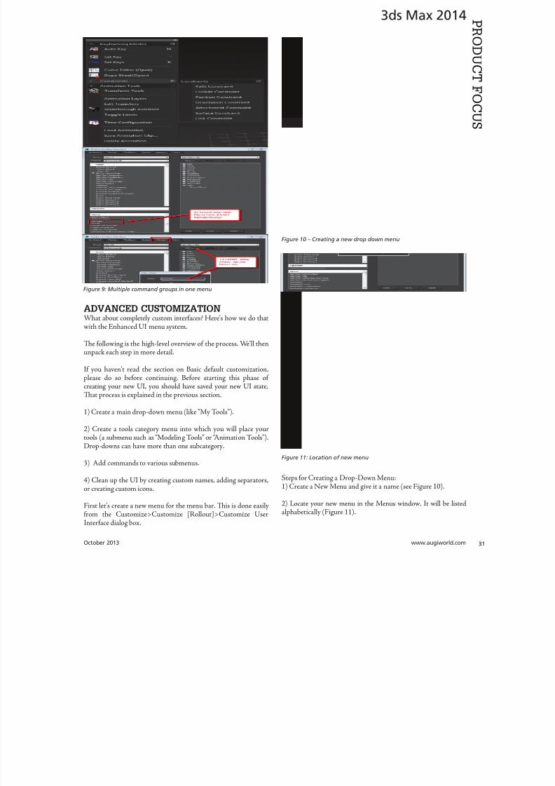
8122019 augi world 2013 10
httpslidepdfcomreaderfullaugi-world-2013-10 3152October 2013 wwwaugiworldcom
3ds Max 2014
ADVANCED CUSTOMIZATION
What about completely custom interfaces Herersquos how we do thatwith the Enhanced UI menu system
Te following is the high-level overview of the process Wersquoll thenunpack each step in more detail
If you havenrsquot read the section on Basic default customizationplease do so before continuing Before starting this phase ofcreating your new UI you should have saved your new UI stateTat process is explained in the previous section
1) Create a main drop-down menu (like ldquoMy oolsrdquo)
2) Create a tools category menu into which you will place yourtools (a submenu such as ldquoModeling oolsrdquo or ldquoAnimation oolsrdquo)Drop-downs can have more than one subcategory
3) Add commands to various submenus
4) Clean up the UI by creating custom names adding separatorsor creating custom icons
First letrsquos create a new menu for the menu bar Tis is done easilyfrom the CustomizegtCustomize [Rollout]gtCustomize UserInterface dialog box
Steps for Creating a Drop-Down Menu1) Create a New Menu and give it a name (see Figure 10)
2) Locate your new menu in the Menus window It will be listedalphabetically (Figure 11)
Figure 9 Multiple command groups in one menu
Figure 10 ndash Creating a new drop down menu
Figure 11 Location of new menu
8122019 augi world 2013 10
httpslidepdfcomreaderfullaugi-world-2013-10 3252wwwaugicom October 20
3ds Max 2014
PRO
DUCT
FOCUS
3) Drag your newly created menu category over to the column onthe right Tis will add your new drop-down menu to the interfaceimmediately and you can begin populating it with menu items (seeFigure 12)
UI DESIGN IP Te actual menu name and display name can bedifferent I used a custom menu name behind the scenes so I couldeasily differentiate my menus from the ones created by default or other
tool companies After you create a menu and add it to the right column you can right-click on it and change its display name (see Figure 13)
Next letrsquos create a command group1) Just like in Step 1 from the previous section create a new men
2) Tis time before you drag it to the right column click thplus sign next to your drop-down menu item to expand it Tedrag the new item to the right column dropping it ldquounderrdquo thmenu name
3) Drag any commands from the Commands window on the leto the submenu on the right (see Figure 15)
Herersquos an example from my Mograph ools workspace thshows how a completed menu looks once it is created (Figu16) In the following figure you see both the menu as it appeain the Customize UI dialog and the actual menu (which has bepeeled off)
Notice that some of the commands on the menu are greyed ouTatrsquos because this new menu combines both ldquoObject creatcommands and ldquoObject Modify Commandsrdquo in one menTey will remain grey until you create an object on which thwill be used
Figure 12 Adding the new menu to the UI
Figure 14 Creating a command group
Figure 15 Dragging commands onto the menu
Figure 13 Custom menu names
8122019 augi world 2013 10
httpslidepdfcomreaderfullaugi-world-2013-10 3352October 2013 wwwaugiworldcom
3ds Max 2014
Adding SeparatorsSeparating commands is easy and is recommended to help you oryour intended user make sense of the how the tools are arranged inthe menu Creating a separator is as easy as dragging one over theright column just like a menu or command
HO IP ldquoWhy do I need to create another menu Why canrsquot I addtools right to my menurdquo
Te main reason is that adding a submenu gives you the ability to tearoff the submenu If it werenrsquot in a submenu it wouldnrsquot be tear-ableSo itrsquos really a ldquobest practicesrdquo kind of thing But even if you try to notadd the submenu it will happen automatically Itrsquos important to do it
explicitly so you are aware of what submenus are in the menu and that you are the one in control of what command is going where
CUSTOM ICONSNo custom UI is complete without a custom set of iconsAdditionally not all commands in 3ds Max have their own iconyet But itrsquos important to realize that regardless of how you set up
your UI yoursquore still working within the framework of an existingapplication and there are boundaries to what you can edit andcreate Icons have specific requirements both in their creation(size) location and file name that must be adhered to in order forthem to work properly
SizeformatTe size of icon is pretty simple It must be 32x32 pixels andPNG format
LocationTe location is very specific New icons must be added to thislocation
CProgram FilesAutodesk3ds Max 2014UI_lnResourcesDarkIconsMain
Te new icons I created for the Mograph UI are shown inFigure 17)
Icon File NameIf yoursquore still with me at this point we are now getting into thenether regions of customizing a UI Tis is where things get a littletricky but itrsquos really not too bad File names are specific and aregenerated by the application (3ds Max)
So letrsquos begin First identify the command for which you want aniconmdashusually itrsquos one that doesnrsquot already have an icon But if itdoes and yoursquore changing it MAKE A BACK UP of the originalicon PNG file Tis is because as previously stated you donrsquot havecontrol over the file name Tat means if yoursquore creating your ownicon you need to overwrite the existing one and use its name foryour new icon So back up any original icons
Figure 16 The completed menu
Figure 17 ndash The created icons
8122019 augi world 2013 10
httpslidepdfcomreaderfullaugi-world-2013-10 3452wwwaugicom October 20
3ds Max 2014
PRO
DUCT
FOCUS
It really doesnrsquot matter whether you make the icon first or not ofind the name you need to use you need to navigate as follows
NOE Yoursquore about to edit the ribbon Tere is no need to save thesechanges as we are merely extracting information from it But if yoursquoredoing a lot of custom icon work you may want to save this change to theribbon so you can come back and continue your work in later sessionswithout have to recreate this every time just to get the proper file nameSaving this ribbon is not related to saving your default state of yourUI When yoursquore done creating all your UI icons you can just delete
whatever changes you make to the ribbon
1) Open the ldquoCustomize Ribbonrdquo dialog box
2) Create a new ldquotabrdquo by dragging it onto the ldquoExisting Ucolumn in the middle (see Figure 18)
3) Using the same drag method add a new ldquopanelrdquo to ttemp tab (Figure 19)
4) Now you can get the information you need Find tcommand for which you are creating an icon and dragto the panel
5) Locate the ldquoinfordquo portion of the ldquoPreview Windocolumn At the bottom of the column is the file namneeded to have the icon used properly by the applicati(Figure 20)
CONCLUSIONSo now you know how to create a custom UI scheme f3ds Max 2014 and up By using the Enhanced UI me
system itrsquos really easy to generate a multitude of workspathat allow Max to work the way you want to work
Te example used in this article was the ldquoMographrdquo UI thI created for NAB 2013 If you would like to downloand install it you can get it from my ldquoPinning the Stacblog on the Area herehttpareaautodeskcomblogschrismurray
Enjoy
Chris Murray works for Autodesk
Media amp Entertainment He istrained as an animator (3D variety)but considers himself a creative tech-nologist His daily role is a technicalldquoevangelistrdquo for Autodesk creating marketing deliverables for 3ds Max Heis the author of Mastering 3D StudioMax He has a Masters in Fine Arts(MFA) in Computer Animation fromMiami International University of Artand Design Follow him on witterchrismmurray
Figure 18 Creating a tab on the ribbon
Figure 19 Adding a panel to the tab
Figure 20 Finding the required file name
8122019 augi world 2013 10
httpslidepdfcomreaderfullaugi-world-2013-10 3552
AUGIMembersReach Higherwith ExpandedBenefitsAUGI is introducing three new Membership levelsthat will bring you more benefits than ever beforeEach level will bring you more content and expertiseto share with fellow members plus provide anexpanded more interactive website publicationaccess and much more
MEMBERMEMBER MEMBER
Basic members haveaccess tobull Forums
bullHotNews (last 12 months)
bull AUGIWorld (last 12 months)
DUES Free
Premier members haveaccess tobull Forums
bullHotNews (last 24 months)
bull AUGIWorld (last 24 months)
DUES $25
Professional members haveaccess tobull Forums
bullHotNews (full access)
bull AUGIWorld (full access and in print)
bull ADN 2013 Standard Membership Offer
DUES $100
Are you ready to upgrade yourself and your membership
Access additional benefits and upgrade at wwwaugicom
8122019 augi world 2013 10
httpslidepdfcomreaderfullaugi-world-2013-10 3652wwwaugicom October 20
AutoCAD MEP 2013
PRO
DUCT
FOCUS
by Vladimir Triantafillid
BIM IsWhatrsquos
Driving theIndustry
For the past decade many would arguethat building information modeling(BIM) has metastasized aggressivelythroughout the AEC industry but what
does BIM really mean More importantly whatdoes it do for us and for our industry Ask someone who hasbeen in this industry for more than 25 years or those nearingretirement and yoursquoll find that less than half see its value muchless care to make the effort with its implementation hesequestions mean something different for those who have beenin the industry the past 10-15 years Recent college graduates
however with their tech-savvy capacity and high expectationare eager to implement anything that resembles cutting-edgflashy technology ypical ly they are the ones most receptivenot adamant about putting their talents to use through BIM
I recently gave a BIM presentation with an emphasis on mchanical systems to the summer interns and new hires our companymdashall were non-BIM users except for onemdashbmy presentation did little justice to BIM Half of my audence had found a cure for their insomnia when they realizthis wasnrsquot the latest edition of ldquoCall of Dutyrdquo hat was n
8122019 augi world 2013 10
httpslidepdfcomreaderfullaugi-world-2013-10 3752October 2013 wwwaugiworldcom
AutoCAD MEP 2013
reflection on BIM by any measure Simply put I fell shortof connecting with a potentially captive audience eager toknow what really makes BIM intriguing or how it wouldgive them an edge in the industry I didnrsquot think to look pastpresenting the facts of its processes and benefits o simplyhave stated that proficiency in any of its many facets willpromote a lucrative career would give those still awake theimpetus to jump ship In hindsight the first step I shouldhave taken to begin this presentation was to ask what theywanted to get out of BIM
If you think itrsquos hard conveying the value and splendor ofBIM to receptive and impressionable young minds try toconvince the weathered veterans dead-set in their ldquooldtricksrdquo For every experienced veteran who has converted toBIM there are two ldquoold dogsrdquo that canrsquot shake ldquothe good olrsquodays when we used vellum and light tablesrdquo Guess whatmdashanincreasing amount of naysayers are starting to come aroundincluding those who say theyrsquove been burned by BIM in thepast hey are seeing the simple solutions BIM presents and
how these solutions translate into cost savings More andmore of those who had formerly questioned BIMrsquos utility areconvinced when installation efficiencies are not only real-ized but quantified
Another factor in the evolution of BIM is its tendency toexpand faster than the pace of its general population of us-ers hose of us proud to be catching up to what we think iscutting edge quickly realize it was just another false sense ofaccomplishment as BIMrsquos web continues to grow exponen-tially he solution is rather simple Focus on what you canhandle and always have the presence of mind and sense ofcaution to avoid being overwhelmed by the wake of BIMrsquos
progress herersquos plenty of money to be made and countlessfacets to explore as long we have the following mentality Welive in the information age and those wi lling to share knowl-edge will reap the rewards of communal synergy
On the opposite end of the spectrum you might find ourindustryrsquos opportunists In a hurried frenzy to claim theirspot in the intellectual property queue these opportunistsget carried away with pioneering what they assume is the lat-est improvements to BIM Instead of stopping to absorb anddevelop the benefits of 4D 5D 6D and so on the pioneersare spreading these ldquoDsrdquo thin with abandon further expand-
ing the gap between quality and quantity None of this i s tosay that wersquore heading in the wrong direction On the con-trary letrsquos call it more of a positive economic problemmdashthedemand for BIM expertise and development outweighs thesupply of available users
Fortunately as collegiate curricula catch on to this industrytrend the point of equilibrium will soon follow For as longas I can remember respective companiesrsquo 2D CAD depart-ments have been a significant source as the breeding groundfor potential BIM users While this route hasnrsquot changedregarding the career path of a draftsperson the source poolhas expanded to include architects engineers and construc-
tion managers just to name a few Itrsquos even hard not to noticeits stark demand when BIM and Revit courses are being in-creasingly offered at local community colleges I knew thenthat you didnrsquot necessarily need an undergraduate degreeback when I got my foot in the door of this industry hisprobably wonrsquot hold true in the coming years Still the privi-leged few who are already a part of this industry subset canrely on their experience in this fast-paced market to con-tinue to propel their careers forward ever faster All thesefew need to do is grab onto a small piece of BIMrsquos wing andhang on tight for the ride he fresh-out-of-college e ntrantsmight have a harder time grabbing onto this wing thatrsquos al-ready in motion
o those who are only vaguely famili ar with BIM it is typi-cally perceived as the equivalent of a 3D role-playing videogame In this case itrsquos not difficult to capture a ldquosnapshotrdquoimage of a 3D model shadows cast across random metal ob-
jects taking up space in an orderly fashion between ceil ingspaces and walls What is difficult is conveying the abun-dance of value behind the pretty picture to a client whorsquosonly interested in the pretty picture Who isnrsquot familiar withthe adage ldquoa picture is worth a thousand wordsrdquo Why notchange that saying to ldquoa BIM model is worth five thousandhyperlinksrdquo Now wersquore talking lifec ycles and facilities man-
More and moreof those who had
formerly questioned
BIMrsquos utilityare convinced
when installationefficiencies are notonly realized but
quantified
8122019 augi world 2013 10
httpslidepdfcomreaderfullaugi-world-2013-10 3852wwwaugicom October 20
AutoCAD MEP 2013
PRO
DUCT
FOCUS
agement his supposed video game has suddenly becomean encyclopedia of usable information But wait itrsquos not juststatic information thatrsquos stuck on a DVD on a shelf i n someownerrsquos random storage closet It has now become a livingdynamic source of real-time data Maintenance technicianswill know exactly where to go when the active 3D modelloaded on their laptop highlights a hot water pump needingservice while concurrently bringing up the cut sheets andoperation and maintenance manuals specific to that pumpor system Better still the source of information has shiftedfrom multiple stacks of large drawing sets collecting dust toseveral hundred gigabytes on a hard drive Yes Mrs Clientyour 3D BIM model will be usable for the next 20+ years
Even though you might not necessarily think about i t someof you probably realize that BIM has become the ldquomiddle-manrdquo for so many key components in the construction cyclewell beyond its intermediary role between design and con-struction phases You want to do some significant tenantimprovement in an existing building Laser-scan the exist-ing conditions hatrsquos BIM Is the general contractor rackingtheir brain trying to f igure out where to station the crane forthe project or pave the pathways for delivery trucks Nowtheyrsquore looking to BIM to answer these questions and opti-mize their decisions o take it a step further at which endof the building do we want to load thousands and thousands
of pounds of sheet metal and pipe And then which tradesshould be installing their systems first in any given area ofthe building hatrsquos right wersquore deriving sequencing andtimelines from the BIM model to e stablish the best routes totake while addressing any constructability issues BIM hasbecome the consultant that wears most of the hats Itrsquos ourone-stop shop
I know that Irsquove personified BIM as if itrsquos the brains behindall of its success Letrsquos take a moment to focus instead on itscollaborators or the sum of its integral parts to show thatin reality we are Dr Frankenstein and BIM is our monster
Except in our ca se wersquore beginning to ta me our monster anthose who were previously frightened by it are starting to sthat it indeed is no monster In fact while evolving to domdashand becomemdashgreater things BIM is transforming into aindustry hero he point of convergence is approaching bcause wersquore saving money time and even trees Soon enougBIM will be the industry standard even on the smaller proects Letrsquos keep the pedal to the meta l
You want to know the best news Most of us havenrsquot evebegun to scratch the surface of BIM but wersquore in strategpositions to reap the rewards aking the possibility of ivast potential into account isnrsquot it reassuring knowing th
in these tough economic times wersquore engaged in an industthat has a shortage of well-qualified BIM experts Our eposure alone sets us up for success Now ask yourselves thquestion Is BIM driving our industry or is it the BIM use
Vladimir riantafillidis works for aleading mechanical contractor in theSan Francisco Bay Area with morethan 10 years of experience in the in-dustry Although he has a bachelorrsquosdegree in biology his unique careerchoices have firmly rooted him in a
substantial BIM role awarding himthe opportunity of progressing along-side the relentless evolution of BIMOutside of his career hersquos always opento new adventures whether trying anew cuisine exotic travels or extremesports Te latter adventures have re-cently subsided as the balance of lifehas shifted his focus on spending timewith his growing family
You want to know the best news Most of us havenrsquot
even begun to scratch the surface of BIM but wersquore
in strategic positions to reap the rewards
8122019 augi world 2013 10
httpslidepdfcomreaderfullaugi-world-2013-10 3952
8122019 augi world 2013 10
httpslidepdfcomreaderfullaugi-world-2013-10 4052wwwaugicom October 20
Revit Structure 2014
PRO
DUCT
FOCUS
Streamlining
Sheet Listswith a Custom
Application
In this article we take a brief look a simpleadd-in for Autodeskreg Revitreg named X-Sheetswhich provides tools for incorporating sheetsfrom an AutoCADreg sheet set in a Revit sheet
list ypically this is handled by manually addingplaceholder sheets to the Revit sheet list Tis can be problematicbecause the sheet list becomes disconnected from the sourceand must be updated manually With X-Sheets sheet set datais exported directly from AutoCAD linked to a Revit project
and included in the sheet list by automatically addingupdatinplaceholder sheets For this example all structural scheduleplans elevations and section sheets are in Revit Structure Adetail sheets will be pulled from an external AutoCAD sheet set
X-SHEETS RIBBON PANEL Te first command on our ribbon panel is Discipline Tcommand is used to establish the Revit project parameter twhich the AutoCAD sheet subsets will be mapped For th
by Jonathan Albe
Figure 1 Revit X-Sheets ribbon panel
8122019 augi world 2013 10
httpslidepdfcomreaderfullaugi-world-2013-10 4152October 2013 wwwaugiworldcom
Revit Structure 2014
example we have created a project parameter named My DisciplineParameter Each Revit Structural sheet has been assigned a valueof SRUCURALmdashthe same as the subset name for theAutoCAD detail sheets Te sheet list is grouped and sorted bythis parameter
Te next command on the ribbon panel is Links Tis command isused to establish a link between the Revit project and XML file(s)
containing sheet information exported from AutoCAD You cancreate as many links as needed and use relative paths if required
Te next two commands Sheets and Update do the work ofaddingupdating placeholder sheets to the sheet list While theSheets command allows you to select individual sheets from linksto include in the sheet list the Update command includes all sheetsfrom all links
EXPORT SHEETS FROM AUTOCADFigure 3 shows the AutoCAD X-Sheets ribbon panel and asample sheet set containing structural detail sheets Notice thedetail sheets are grouped under a subset named SRUCURALTis subset name can be exported with each sheet and mapped to
the My Discipline Parameter in Revit Figure 3 shows the ExportSheets dialog with an option to include subset information and theability to exclude individual sheets Selecting the Export buttonprompts us with a dialog to save an XML file to be linked into ourRevit project
Figure 2 Discipline command dialog
Figure 3 AutoCAD X-Sheets ribbon panel and sample sheet set
Figure 4 Export sheets dialog
Figure 5 Export complete
8122019 augi world 2013 10
httpslidepdfcomreaderfullaugi-world-2013-10 4252wwwaugicom October 20
Revit Structure 2014
PRO
DUCT
FOCUS
ESTABLISH LINK TO XML FILE IN REVIT
PROJECTFigure 6 shows the Manage Links dialog A link has been added tothe XML file we generated when exporting sheets from AutoCADNotice there is an option to make the link path relative to our
Revit Project location
IMPORT SHEETS FROM XML LINKFigure 7 shows the Revit Structure sheet list before any sheetshave been imported from AutoCAD After selecting the Sheetscommand we are prompted with a Manage Sheets dialog
For this example we have selected all sheets from the XML linto include in our sheet list After confirming the dialog neplaceholder sheets are immediately added to the sheet list angrouped according to the SubsetDiscipline mapping Te neplaceholder sheets are identified behind the scenes as being relatto the X-Sheets XML link for later updating
Figure 6 Manage Links dialog
Figure 9 Sheet list after import
Figure 7 Sheet list before import
Figure 8 Manage Sheets dialog
The X-Sheets
add-in is a great tool
for incorporating
AutoCAD sheets into
a Revit sheet list
8122019 augi world 2013 10
httpslidepdfcomreaderfullaugi-world-2013-10 4352October 2013 wwwaugiworldcom
Revit Structure 2014
UPDATE SHEETSFigure 10 shows the Export Sheets dialog in AutoCAD afterdetail sheets have been renumbered to include ldquo-Ardquo When changesare made to AutoCAD sheets the original export steps must befollowed to replace the XML file linked to our Revit project Oncethe XML has been replaced simply run the Update command inRevit to update the sheet list
SUMMARYTe X-Sheets add-in is a great tool for incorporating AutoCADsheets into a Revit sheet list Te add-in saves time by automatically
adding placeholder sheets eliminates room for error in manualtranslation and helps to keep your sheet list up to date withminimal effort
Jonathan Albert is co-founder of BIM- pulse echnologies LLC amp SeniorApplications Developer at LindemanBentzon Bojack Engineering in Cler-mont Florida He has worked morethan 15 years implementing and usingBIM echnology for some of the na-tionrsquos leading production home build-
ers Most recently he has developedBIMpulse an Options Managementand Material akeoff Add-In for Au-toCAD Architecture Revit and Au-todesk Design Review Jonathan can bereached at jonalbbecom
Figure 10 Export Sheets dialog after sheet renumber
Figure 11 Update complete
Figure 12 Sheet list after update
The X-Sheets
add-in is agreat tool for
incorporatingAutoCAD
sheets intoa Revit
sheet list
8122019 augi world 2013 10
httpslidepdfcomreaderfullaugi-world-2013-10 4452wwwaugicom October 20
AutoCAD Civil 3D 2014
PRO
DUCT
FOCUS
by Tench Tilghma
Itrsquos a fact Jack You invested money in the worldrsquosmost popular civil engineering and designsoftware You (or someone else) will have workhard to make the software run productively
and publish the engineering design or surveywork acceptably
Every AutoCADreg Civil 3Dreg user will tell you ldquoYou need a Civil3D templaterdquo
heyrsquore right sort of You need more than one he suppliedexample Autodesk template files (dwt) are just thatmdashexamplesto show you that things are possible A great many ldquothingsrdquo arepossible in Civil 3D It is data-centric model-based software Asa dedicated content developer and continuous customizer of Civil3D I hope the following perspectives and tips help shorten thecycles and reduce the pain of customizing the software
AutoCAD Civil 3D was constructed from the ground up todisconnect the survey and engineering data from how that missioncritical data is represented
WITH LIBERTY COMES RESPONSIBILITYAs far as Autodesk is concerned what you want the many Civil 3Dldquothingsrdquo to look like and how the Civil 3D data is to be annotated istotally up to you hatrsquos not really true is it Plan sets are publishedin arcane symbolic graphic languages designed to faithfully conveythe design intent to someone who must build it with a plan checkeror two (or three or four) stuck in between
As a professional I prefer to call them ldquoPlan Set Languagesrdquo hhelps focus the development to the publishing of Civil 3D datMost people throw a fuzzy word around this complex mix human perceptive agendas and call that ldquoCAD Standardsrdquo
ldquohe wonderful thing about standards is there are so many of themndash Grace Hopper et al
PICK A STANDARD AND MANAGE BY ITldquoWe already have a CAD standardrdquo his may be the first anworst Civil 3D customization mistake any skilled AutoCAD usor organization can make he odds are the CAD standards yoemployed before do not take into account the data centric anmodel-based methods that Civil 3D employs Simply put Civ3D manages how things look and behave by Style Primitive-basAutoCADreg standards may get in the way
Older ldquoCADrdquo standards by definition must be focused on CAprimitive publishing specifics layer textstyle (height) blo
CustomizeCorrectly
Figure 1 Standards documentation is required
8122019 augi world 2013 10
httpslidepdfcomreaderfullaugi-world-2013-10 4552October 2013 wwwaugiworldcom
AutoCAD Civil 3D 2014
graphics standards and so on In raw AutoCAD and AutoCAD-based drafting and design software the only way to manage all theCAD primitive stuff was to be SPECIFIC about all the details allthe time he drawing we create and check things in is the drawingwe publish
If you publish work out of quality control or design drawingsin Civil 3D this is a sign you may be missing some of its timesaving advantages
While the old CADD process works it requires a lot of man-hoursdedicated to maintaining and checking the details Clearly one ofCivil 3Drsquos critical design development goals is to rid organizationsand Civil 3D users of this expensive man-hour burden and costhe idea here is to put the man-hours into the iterative engineeringprocess instead Civil 3D Feature data and Style make this possible
Civil 3D styles and label styles do employ the AutoCAD layertextstyle block references AutoCAD customizers are used tohe software is still called ldquoAutoCADrdquo Civil 3D after all Our
AutoCAD customization skills still apply But we must applythem differently and much more systematically Herersquos whyhellip
YOU NAME ITmdashTHE MOST CRITICAL
STANDARDCivil 3D Styles and label styles employ (reference) the AutoCADldquonamedrdquo parts to ldquoexpressrdquo themselves Style tools just look for andmatch the ldquorightrdquo names Change the ldquomeaningrdquo andor definitionof the names and you can change anything
We call this fundamental property and benefit of object-orientedprogramming the Power of Names In programming speak this
concept and practical reality is called a ldquonamespacerdquo
Such a namespace in engineering speak answers the questionldquoIn this context does ldquoDIrdquo means a ldquodrop inletrdquo In a minute wersquollget to the structure of a customization ldquonamespacerdquo for Civil 3DAutoCAD references
THE POWER OF NAMESGo ahead and make a drawing from your current Civil 3D templateoss in some Civil 3D data by data reference from any projectUse the RENAME command on any of the old AutoCAD stylecollectionsmdashtry layers
Rename like crazy Your existing Civil 3D styles and label styles willhappily work exactly the same he components in the Civil3DFeature and Label Styles will go to your renamed layers Becauseyou didnrsquot change the properties of the layers either nothingchanges Itrsquos not too exciting until you think about what it means
FOLLOW A SCRIPTObviously as customizers we never want to do this sort of workmanually Computers are faster better and more exact typists thanwe are We commonly rely on AutoCAD scripts generated from
Microsoft Excel spreadsheets (See the end of the article)
here are a couple of key collections in the object model thatCivil 3D walls off from this form of potentially destructiveuser madnessmdashObject Properties in Drawing Settings and afew things like Figure Prefix Dbs values that are not ever in thedrawing per se
WHAT REALLY MATTERSAutoCAD Civil 3D style is mind-boggling abstraction Everythingis designed and built to point at references We can employ styleabstraction for our benefit
In one sense AutoCAD Civil 3D style doesnrsquot care aboutAutoCAD layer standards block libraries textstyles colorsplotstyles or really anything else AutoCAD From our perspectiveall the Civil 3D styles care about are the arbitrary and exact namesthey currently reference
he Civil 3D customizerrsquos dilemma Keep book on the exactnames here are a lot of names to keep track of You must havea plan You must have rules You must employ the same processesconsistently in the same order to get quality assured results
Figure 2 Are description keys a namespace
Figure 3 Rename the AutoCAD reference names
8122019 augi world 2013 10
httpslidepdfcomreaderfullaugi-world-2013-10 4652wwwaugicom October 20
AutoCAD Civil 3D 2014
PRO
DUCT
FOCUS
hat Current word is a wonderfully relative term forthe customizer
Build a set of styles extract them to another drawing rename andor redefine the references and quickly produce a different resulthe Current method makes it easy to propagate success andmistake It makes it repetitively tedious to make fixes
NO CAN STOPAs innovative content developers for Civil 3D we chose to employthe National CAD Standard (NCS) as our fundamental Namestandard Not because we like the NCS but because of all thehard-won experience expressed in these tested standards Inmany respects we employ the NCS UDS (Uniform DrawingStandards) etc in our Production Solution products becauseof the underlying How and Why for those standards and theirpractical published Rules
We want to build faster high-performance vehicles Why reinventthe wheel when we can improve on it
STANDARD KEYS TO NAMEShe NCS employs a hierarchical concept of Keys here areMajor Keys Minor Keys etc that have order precedence and aninterpreted meaning he NCS Layer standard employs the Key-based rules to produce defined meanings to Layers
You can in practice employ the same Layer Keys to be genericor granularly specific about where the published results go Allthe annotation can go to one layer or many different layers forexample Styles andor sets do the work
his KEY CODE structure produces a flexible and structuredldquonamespacerdquo we referred to earlier Itrsquos a namespace that both thesoftware can employ and is relatively easy for us dumb-bunnyhumans to learn to decode when we must Most of the time theusers donrsquot and shouldnrsquot care anyway
Figure 4 shows a few of the NCS ldquolikerdquo Keys we employ in ourproducts We employ them for both layer and block collectionsand even the structure of libraries hey may even be employedin Civil 3D style names when thatrsquos appropriate (See the endof the article)
he customizing key point is that the meanings of these specificKeys can be translated into any other set (or sets) of different
Keys he Key changes can be systematically applied to whatevAutoCAD reference tables and resources we require
he results of any changes will float uphill to the named Civil 3Styles we choose to employ hink of all the AutoCAD referencin a template as a Set
BEYOND AUTOCADNow wersquove looped back to Civil 3D style tools and substantivetheir names and what their parts refer to Welcome to the circuland iterative world that is customizing and employing Civil 3D
Aside from the requisite customization skills and experience build style tools our practical biggest customization issues afrankly Civil 3D human interface issues
No matter how you cut it you have a very limited amount of tespace to help users decide on the ldquorightrdquo style tool to use he teof the style toolrsquos name is all you get to deliver to the user ypicaitrsquos a pick box list
You might get lucky and have the Style Viewer but that Viewcannot represent everything a style can do
FEATURE STYLES NAMESWhat we call the ldquoFeature Stylesrdquo (the Ci3D Featurersquos graphics) require that our stynames explain in simple readable humterms what the tool does For examplesurface style like ldquoContours 1-5 Proposed
Figure 4 Some standard keys
Figure 5 The limitations of user style choice
8122019 augi world 2013 10
httpslidepdfcomreaderfullaugi-world-2013-10 4752October 2013 wwwaugiworldcom
AutoCAD Civil 3D 2014
For the common and most understood features this makes somesense ASCII order rules how named Styles organize Names mustsort that out
Complex graphic features such as Views have a lot more going onldquoMy Standard Profile Viewrdquo doesnrsquot cut it except in a publishingtemplate he style names must be more informative and specificDoes the Profile View include grid lines or not We must recognizethat the engineering data behind what we want to visualize isvariable and the user will have specific needs to get work doneWhen you check a surface you need to see the data in differentways than when the result is published
Choice of style is productive Choice is not contrary to publishingstandards unless you mix the two
LABEL STYLE NAME FACTORSWhen we open the Alignment Label Style collection andorstart to assemble Sets of Label Styles we see any hope of namesimplicity for label styles disappears in a flash
he majority of styles are annotative here are a lot of formsand specific types of them Label Style ype matters he smartcustomizer employs the Label Style Default (LSD) hierarchyexpressed in the oolspacegtgtSettings tab or ignores it and missesthe benefits
Label styles often must have a geometric framework to themItrsquos about ldquoreadabilityrdquo and meaning Whether this label goes upor down or attaches here and not there is critical to annotativeclarity he graphic structure of many data-rich label styles alsofundamentally matters to the stylersquos upgrade stability herersquos
a maintenance cost to pay if you refuse to employ consistentgeometric structures in label styles
CUSTOM USAGECan users see the right data and at the right time Will the useremploy a general alignment parcel or figure line and curve labelHow do they see the difference in a simple list It is easy to misshow ldquoon-the-flyrdquo annotative information negatively or positivelyeffects design time decision making and quality control Peoplewill make things to get the job done Do you fight it or enable ithe Simple Style Rules anyone can learn
THE CIVIL 3D NAMESPACESA Civil 3D style naming convention must be human readablecreate order in the interface and therefore include a rule-basedeasy-to-learn code system that expresses quickly the critical detailso customize we need two namespaces One for the top-end stylesand one for the back-end AutoCAD references In productionprojects we need a third namespace for how we name the featuresbut thatrsquos another story
his client and this project demand these CAD standards specificsAnother client and project demand something different Even ifyou donrsquot believe you regularly face that common problem you
still have to improve the internal production templates themselveshe method and process arenrsquot different
In our project-based production world Civil 3D users andsupervisory staff can always work with the familiar and publishwhat is demanded in a customized publishing template hetwo-pronged project template approach has the added benefit ofpotentially quantifying the costs and real return on investment forthe customization itself
CUSTOMIZE TO PUBLISH ON DEMANDIn practical terms we can change the expressed graphicsmdashthe PlanSet Language (CAD standards) with managed intern level staffEven non-CAD people can see and identify graphic differenceOnly basic AutoCAD and basic spreadsheets skills are requiredfor much of the work if you have a naming plan ldquoChange thatmanhole block to look like this manhole blockrdquo Your ldquothatrdquo mustbe specific
ldquoPublish on demandrdquo capability is a productivity and competitive
advantage but it takes repetitions to develop and practice the skillsWe must endlessly customize Civil 3Dmdashreap the benefits
CIVIL 3D NAME RESOURCEShe Standard Keys the NCS-like AutoCAD reference namespacehe Jump Standards includes the detailed and documented stylenamespace Find them at wwwcadpilotcomresourcesaspx
Excel Cell Formula Script ExampleHerersquos the pseudo code for a typical formula-based layer script thatmakes a layer table with all the details filled in from a cell It createsa series of quote wrapped strings when a column of such cells is
copied and pasted to an ASCII text file
ltLayerCommandgtampCHAR(13)amprdquoSrdquoampCHAR(13)ampltOldLayergtampCHAR(13)amprdquoRrdquoampCHAR(13)ampltNewLayergtampCHAR(13)ampltNewLayergtampCHAR(13)amprdquoCrdquoampCHAR(13)ampltColorgtampCHAR(13)ampCHAR(13)amprdquoLWrdquoampCHAR(13)ampltLineweightgtampCHAR(13)ampCHAR(13)amprdquoPSrdquoampCHAR(13)ampltPlotstylegtampCHAR(13)ampCHAR(13)amprdquoDrdquoampCHAR(13)ampltDescriptiongtampCHAR(13)ampltNewLayergtampCHAR(13)
ench ilghman is President ofMoreCompetency Inc an Autodesk
Developer Partner specializing in in-novative Civil 3D Production Solu-tion products and consulting services
for AutoCAD Civil 3D ench is aregular speaker at Autodesk Univer-sity and AEC industry events on thetopics of technology adoption innova-tion and (his personal favorite) peopleskills He posts on the Get the Jump onCivil 3D blog
8122019 augi world 2013 10
httpslidepdfcomreaderfullaugi-world-2013-10 4852wwwaugicom October 20
Revit MEP 2014
PRO
DUCT
FOCUS
by Todd Shackelfor
W
hen any new technology hits theground there are plenty of false startsand backtracking In time shortcutsare found tricks of the trade are
discovered and best practices are defined So is thecase with Autodeskreg Revitreg even for MEP users his article willoutline a logical roadmap of technical and non-technical mustdorsquos and donrsquot dorsquos for transitioning to Revit MEP From settingexpectations defining goals and plotting in Revit to addressingBIM IPD and VDC the checklist of elements required to helpRevit really work in an office will be covered Every implementationwill come with resistance workflow issues and plenty of headachesbut staying on course and hitting the important milestones alongthe way will help reduce stress of something akin to the craziestfamily trip ever
FIRST CONSIDERATIONS ndash SOFTWAREOne might think it is all about Revit he truth is that Revit reallywants to act as a central location for data that is constantly on themove Much like a smartphone leverages the power of thousandsof applications Revit plugs into workflows with more than a fewAutodesk programs as well as a host of third-party programs hesimple fact that the Building Design Suite comes with so manyvaried applications is a pretty big hint that Revit wants to play ona team Firms need to look at their processes from a high level andlook for the best workflows and programs for the team
FIRST CONSIDERATIONS ndash HARDWAREEvaluate the PCs and know what their capabilities are anknow what Revit requires Search Autodeskrsquos website for systerequirements for Revit products Requirements for three tieof deployment are listed for systems covering an entry-levconfiguration a balanced performance configuration and performance configuration Certified and supported graphi
hardware is also accessible from this page he non-hardwasavvy should seek input from an I professional Revit cannand will not perform on outdated or entry-level PCs and thperson leading the implementation usually takes the blame wheexpectations fall short Best advice is overkill it on hardware Whseems over the top today is inadequate in a year
FIRST CONSIDERATIONS ndash TRAININGhere is no way to get around the fact that training will need tbe done Even if every person in the firm has already used Revtraining on using Revit company standards must still take plachere are many ways to deliver training An in-house expe
TransitionRoadmap
8122019 augi world 2013 10
httpslidepdfcomreaderfullaugi-world-2013-10 4952October 2013 wwwaugiworldcom
Revit MEP 2014
can provide just-in-time all the time Autodesk resellers andconsultants typically provide three- to five-day immersion trainingand short- to long-term consulting here are countless web-based training optionsmdashfree and paid Community colleges thatoffer Revit training usually require a final project that will putstudents through the paces and better entrench the
knowledge and skills
On the down side Revit MEP-specific classes areall but impossible to find Lastly the extreme go-getter can buy a book and learn on the job In realityeveryone learns differently and being preparedto leverage all these types of training is the bestsolution People will gravitate to the solution thatworks best for them when it is provided
FIRST CONSIDERATIONS ndash
LINE UP YOUR DUCTS (UGH hellip
DUCKS)Set appropriate goals based on the size of thefirm Small medium and large firms will havedrastically different goals and timelines It mightseem odd but small firms have the upper hand inadopting new technologies and processes hinkabout it What is easiermdashgetting 3 people toagree or 300 Recognize that an AE firm will havecompletely different goals and processes than a solely MEP firmDuring any shift in process be prepared to support the old andnew at the same time and sometimes in the same project hiswill mean keeping symbols in Revit as close as possible to symbols
in AutoCADreg Consider how quality reviews are done and clientexpectations When things look different it is an impediment tochange Minimizing the impediments will help tremendously
All that being said communication is the real key to most everyprojectrsquos success It is important keep information flowing upand down the chain and set the expectations early Some criticalexpectations for this type of implementation are that things will gowrong things will take longer things will look different things willhave to change and things will continue to evolve Remind usersand management of the progress they have been made by trackingand documenting incremental goals
With a general direction and expectations set itrsquos time to get morespecific about the journey his trip is a long one and a phasedapproach is best Firms can tailor the following phasing to suitindividual needs his example has four phasesmdasheach with itsown goals building off the previous phases
Phase 1 - Goals1 Create construction documents2 Improved collaboration3 Interference mitigationo obtain these goals the following Revit items need to be addressedhe first group addresses the goal of good construction documentshe second group deals with process and keeping things standardhe space available in this article doesnrsquot allow for ldquoHow torsquosrdquo foreach item but each is well documented in the Revit help pageand all over the Internet Get a couple points of view and marrythe possibilities to the culture and needs of the firm in question
bull Line styles createdbull Fonts set for plan text titles title blocks tags and everything
elsebull Object styles ndash Define the weight color tone and transparency
of everything bull Incorporation of standard detailsbull Browser organization ndash Decide how you want to see views
organizedbull Filters ndash Know if you need standard filters and create them
ahead of timebull Phasesbull View templatesbull Project templatebull Duct Stylesbull Pipe stylesbull Family creation
Figure 1
Figure 2
8122019 augi world 2013 10
httpslidepdfcomreaderfullaugi-world-2013-10 5052
8122019 augi world 2013 10
httpslidepdfcomreaderfullaugi-world-2013-10 5152October 2013 wwwaugiworldcom
Inside Track
CSCrsquos Integratorhttpwwwcscworldcom
Integrator is a tool that allows you to synchronize structural designscreated in CSCrsquos Fastrak Building Designer (steel building designsoftware) and Orion (structural concrete building design software)with Autodeskreg Revitreg 2014
ldquoLeading structural software provider CSC has released a new versionof Integrator its market leading Structural BIM integration softwarefor synchronizing code-compliant models produced in CSCrsquos buildingdesign software Fastrak and Orion with Autodeskreg Revitreg Nowfully compatible with Autodesk Revit 2014 structural engineers andtechnicians have even greater control during the integration process
Using Integrator full and part models can be synchronized betweenFastrak or Orion and Autodesk Revit with the ability to manageadded deleted and modified members and their associated
design datardquo
BiMTOOLShttpwwwsofistikcom
BiMOOLS is a set of productivity tools that are designed forAutodeskreg Revitreg 2014 Te plug-in can be installed from theAutodesk Exchange Apps store
ldquoTe first international version of the SOFiSiK BiMOOLS isnow available SOFiSiK BiMOOLS is a collection of free tools forAutodeskreg Revitreg Structure to enhance the productivity up to 50Te features range from easy font type substitution and automaticgeneration of dimensional lines over the automatic positioning ofstructural elements to the comprehensive Family Creator to generatefamilies of eg beams braces and columns for optimal communicationwith FE analysis tools like the SOFiSiK softwarerdquo
Find further information and download links for Revit 2012 and
2013 on the dedicated BiMOOLS website
Autodesk AutoCAD 360 21httpswwwautocad360com
Autodeskreg AutoCADreg 360 is a mobile and web-based application that allows you to view editand share drawing files created with AutoCADand AutoCAD-based products Te mobile appis available from the Apple iunes App Store andGoogle Play Store
ldquoAutoCAD 360 is a free easy-to-use drawing and drafting mobileapp that allows you to view edit and share AutoCAD drawingsmdashanytime anywhere Simplify site visits and fieldwork with powerfuldesign review and markup toolsmdashavailable online and offline
Seamlessly share drawings with others across desktop web andmobile devices Easily access drawings from web browsers using
the free companion AutoCAD 360 web app AutoCAD 360Pro subscription plans further expand the functionality of
the app bringing additional capabilities to the fieldrdquo
Te updates that are in this latest release arebull Stunning high-resolution drawings display
via full retina supportbull Better display through improved PDF
supportbull Easy switching between metric and imperial
unitsbull Saves time with faster app loading bull Improved collaboration through in-app
notifications and streamlined sharing bull New properties for Properties Palette
(Pro version)
AUGIWorldbrings
you recentdevelopmentsin Autodeskand AEC-relatedsoftwareitems
Until next issue
If you have some news to share with us for future issues please let usknow Likewise if you are a user of a featured product or news itemand would like to write a review we want to know
By Lee Ambrosius
8122019 augi world 2013 10
httpslidepdfcomreaderfullaugi-world-2013-10 5252
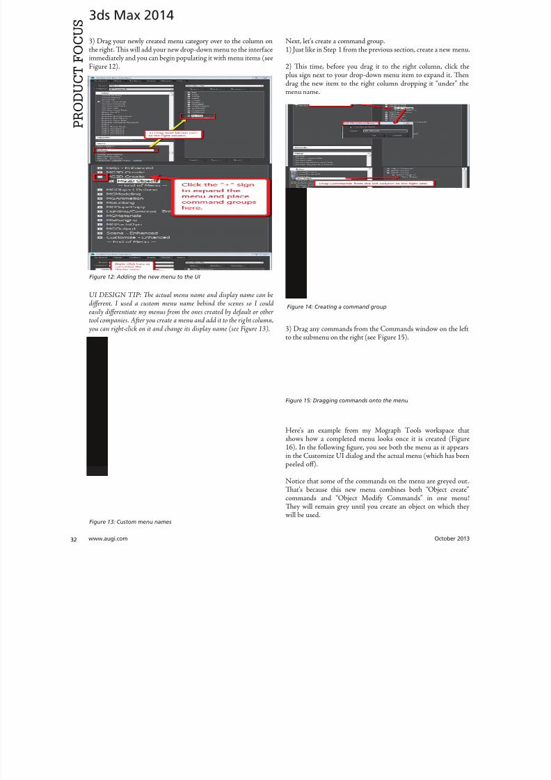
8122019 augi world 2013 10
httpslidepdfcomreaderfullaugi-world-2013-10 3252wwwaugicom October 20
3ds Max 2014
PRO
DUCT
FOCUS
3) Drag your newly created menu category over to the column onthe right Tis will add your new drop-down menu to the interfaceimmediately and you can begin populating it with menu items (seeFigure 12)
UI DESIGN IP Te actual menu name and display name can bedifferent I used a custom menu name behind the scenes so I couldeasily differentiate my menus from the ones created by default or other
tool companies After you create a menu and add it to the right column you can right-click on it and change its display name (see Figure 13)
Next letrsquos create a command group1) Just like in Step 1 from the previous section create a new men
2) Tis time before you drag it to the right column click thplus sign next to your drop-down menu item to expand it Tedrag the new item to the right column dropping it ldquounderrdquo thmenu name
3) Drag any commands from the Commands window on the leto the submenu on the right (see Figure 15)
Herersquos an example from my Mograph ools workspace thshows how a completed menu looks once it is created (Figu16) In the following figure you see both the menu as it appeain the Customize UI dialog and the actual menu (which has bepeeled off)
Notice that some of the commands on the menu are greyed ouTatrsquos because this new menu combines both ldquoObject creatcommands and ldquoObject Modify Commandsrdquo in one menTey will remain grey until you create an object on which thwill be used
Figure 12 Adding the new menu to the UI
Figure 14 Creating a command group
Figure 15 Dragging commands onto the menu
Figure 13 Custom menu names
8122019 augi world 2013 10
httpslidepdfcomreaderfullaugi-world-2013-10 3352October 2013 wwwaugiworldcom
3ds Max 2014
Adding SeparatorsSeparating commands is easy and is recommended to help you oryour intended user make sense of the how the tools are arranged inthe menu Creating a separator is as easy as dragging one over theright column just like a menu or command
HO IP ldquoWhy do I need to create another menu Why canrsquot I addtools right to my menurdquo
Te main reason is that adding a submenu gives you the ability to tearoff the submenu If it werenrsquot in a submenu it wouldnrsquot be tear-ableSo itrsquos really a ldquobest practicesrdquo kind of thing But even if you try to notadd the submenu it will happen automatically Itrsquos important to do it
explicitly so you are aware of what submenus are in the menu and that you are the one in control of what command is going where
CUSTOM ICONSNo custom UI is complete without a custom set of iconsAdditionally not all commands in 3ds Max have their own iconyet But itrsquos important to realize that regardless of how you set up
your UI yoursquore still working within the framework of an existingapplication and there are boundaries to what you can edit andcreate Icons have specific requirements both in their creation(size) location and file name that must be adhered to in order forthem to work properly
SizeformatTe size of icon is pretty simple It must be 32x32 pixels andPNG format
LocationTe location is very specific New icons must be added to thislocation
CProgram FilesAutodesk3ds Max 2014UI_lnResourcesDarkIconsMain
Te new icons I created for the Mograph UI are shown inFigure 17)
Icon File NameIf yoursquore still with me at this point we are now getting into thenether regions of customizing a UI Tis is where things get a littletricky but itrsquos really not too bad File names are specific and aregenerated by the application (3ds Max)
So letrsquos begin First identify the command for which you want aniconmdashusually itrsquos one that doesnrsquot already have an icon But if itdoes and yoursquore changing it MAKE A BACK UP of the originalicon PNG file Tis is because as previously stated you donrsquot havecontrol over the file name Tat means if yoursquore creating your ownicon you need to overwrite the existing one and use its name foryour new icon So back up any original icons
Figure 16 The completed menu
Figure 17 ndash The created icons
8122019 augi world 2013 10
httpslidepdfcomreaderfullaugi-world-2013-10 3452wwwaugicom October 20
3ds Max 2014
PRO
DUCT
FOCUS
It really doesnrsquot matter whether you make the icon first or not ofind the name you need to use you need to navigate as follows
NOE Yoursquore about to edit the ribbon Tere is no need to save thesechanges as we are merely extracting information from it But if yoursquoredoing a lot of custom icon work you may want to save this change to theribbon so you can come back and continue your work in later sessionswithout have to recreate this every time just to get the proper file nameSaving this ribbon is not related to saving your default state of yourUI When yoursquore done creating all your UI icons you can just delete
whatever changes you make to the ribbon
1) Open the ldquoCustomize Ribbonrdquo dialog box
2) Create a new ldquotabrdquo by dragging it onto the ldquoExisting Ucolumn in the middle (see Figure 18)
3) Using the same drag method add a new ldquopanelrdquo to ttemp tab (Figure 19)
4) Now you can get the information you need Find tcommand for which you are creating an icon and dragto the panel
5) Locate the ldquoinfordquo portion of the ldquoPreview Windocolumn At the bottom of the column is the file namneeded to have the icon used properly by the applicati(Figure 20)
CONCLUSIONSo now you know how to create a custom UI scheme f3ds Max 2014 and up By using the Enhanced UI me
system itrsquos really easy to generate a multitude of workspathat allow Max to work the way you want to work
Te example used in this article was the ldquoMographrdquo UI thI created for NAB 2013 If you would like to downloand install it you can get it from my ldquoPinning the Stacblog on the Area herehttpareaautodeskcomblogschrismurray
Enjoy
Chris Murray works for Autodesk
Media amp Entertainment He istrained as an animator (3D variety)but considers himself a creative tech-nologist His daily role is a technicalldquoevangelistrdquo for Autodesk creating marketing deliverables for 3ds Max Heis the author of Mastering 3D StudioMax He has a Masters in Fine Arts(MFA) in Computer Animation fromMiami International University of Artand Design Follow him on witterchrismmurray
Figure 18 Creating a tab on the ribbon
Figure 19 Adding a panel to the tab
Figure 20 Finding the required file name
8122019 augi world 2013 10
httpslidepdfcomreaderfullaugi-world-2013-10 3552
AUGIMembersReach Higherwith ExpandedBenefitsAUGI is introducing three new Membership levelsthat will bring you more benefits than ever beforeEach level will bring you more content and expertiseto share with fellow members plus provide anexpanded more interactive website publicationaccess and much more
MEMBERMEMBER MEMBER
Basic members haveaccess tobull Forums
bullHotNews (last 12 months)
bull AUGIWorld (last 12 months)
DUES Free
Premier members haveaccess tobull Forums
bullHotNews (last 24 months)
bull AUGIWorld (last 24 months)
DUES $25
Professional members haveaccess tobull Forums
bullHotNews (full access)
bull AUGIWorld (full access and in print)
bull ADN 2013 Standard Membership Offer
DUES $100
Are you ready to upgrade yourself and your membership
Access additional benefits and upgrade at wwwaugicom
8122019 augi world 2013 10
httpslidepdfcomreaderfullaugi-world-2013-10 3652wwwaugicom October 20
AutoCAD MEP 2013
PRO
DUCT
FOCUS
by Vladimir Triantafillid
BIM IsWhatrsquos
Driving theIndustry
For the past decade many would arguethat building information modeling(BIM) has metastasized aggressivelythroughout the AEC industry but what
does BIM really mean More importantly whatdoes it do for us and for our industry Ask someone who hasbeen in this industry for more than 25 years or those nearingretirement and yoursquoll find that less than half see its value muchless care to make the effort with its implementation hesequestions mean something different for those who have beenin the industry the past 10-15 years Recent college graduates
however with their tech-savvy capacity and high expectationare eager to implement anything that resembles cutting-edgflashy technology ypical ly they are the ones most receptivenot adamant about putting their talents to use through BIM
I recently gave a BIM presentation with an emphasis on mchanical systems to the summer interns and new hires our companymdashall were non-BIM users except for onemdashbmy presentation did little justice to BIM Half of my audence had found a cure for their insomnia when they realizthis wasnrsquot the latest edition of ldquoCall of Dutyrdquo hat was n
8122019 augi world 2013 10
httpslidepdfcomreaderfullaugi-world-2013-10 3752October 2013 wwwaugiworldcom
AutoCAD MEP 2013
reflection on BIM by any measure Simply put I fell shortof connecting with a potentially captive audience eager toknow what really makes BIM intriguing or how it wouldgive them an edge in the industry I didnrsquot think to look pastpresenting the facts of its processes and benefits o simplyhave stated that proficiency in any of its many facets willpromote a lucrative career would give those still awake theimpetus to jump ship In hindsight the first step I shouldhave taken to begin this presentation was to ask what theywanted to get out of BIM
If you think itrsquos hard conveying the value and splendor ofBIM to receptive and impressionable young minds try toconvince the weathered veterans dead-set in their ldquooldtricksrdquo For every experienced veteran who has converted toBIM there are two ldquoold dogsrdquo that canrsquot shake ldquothe good olrsquodays when we used vellum and light tablesrdquo Guess whatmdashanincreasing amount of naysayers are starting to come aroundincluding those who say theyrsquove been burned by BIM in thepast hey are seeing the simple solutions BIM presents and
how these solutions translate into cost savings More andmore of those who had formerly questioned BIMrsquos utility areconvinced when installation efficiencies are not only real-ized but quantified
Another factor in the evolution of BIM is its tendency toexpand faster than the pace of its general population of us-ers hose of us proud to be catching up to what we think iscutting edge quickly realize it was just another false sense ofaccomplishment as BIMrsquos web continues to grow exponen-tially he solution is rather simple Focus on what you canhandle and always have the presence of mind and sense ofcaution to avoid being overwhelmed by the wake of BIMrsquos
progress herersquos plenty of money to be made and countlessfacets to explore as long we have the following mentality Welive in the information age and those wi lling to share knowl-edge will reap the rewards of communal synergy
On the opposite end of the spectrum you might find ourindustryrsquos opportunists In a hurried frenzy to claim theirspot in the intellectual property queue these opportunistsget carried away with pioneering what they assume is the lat-est improvements to BIM Instead of stopping to absorb anddevelop the benefits of 4D 5D 6D and so on the pioneersare spreading these ldquoDsrdquo thin with abandon further expand-
ing the gap between quality and quantity None of this i s tosay that wersquore heading in the wrong direction On the con-trary letrsquos call it more of a positive economic problemmdashthedemand for BIM expertise and development outweighs thesupply of available users
Fortunately as collegiate curricula catch on to this industrytrend the point of equilibrium will soon follow For as longas I can remember respective companiesrsquo 2D CAD depart-ments have been a significant source as the breeding groundfor potential BIM users While this route hasnrsquot changedregarding the career path of a draftsperson the source poolhas expanded to include architects engineers and construc-
tion managers just to name a few Itrsquos even hard not to noticeits stark demand when BIM and Revit courses are being in-creasingly offered at local community colleges I knew thenthat you didnrsquot necessarily need an undergraduate degreeback when I got my foot in the door of this industry hisprobably wonrsquot hold true in the coming years Still the privi-leged few who are already a part of this industry subset canrely on their experience in this fast-paced market to con-tinue to propel their careers forward ever faster All thesefew need to do is grab onto a small piece of BIMrsquos wing andhang on tight for the ride he fresh-out-of-college e ntrantsmight have a harder time grabbing onto this wing thatrsquos al-ready in motion
o those who are only vaguely famili ar with BIM it is typi-cally perceived as the equivalent of a 3D role-playing videogame In this case itrsquos not difficult to capture a ldquosnapshotrdquoimage of a 3D model shadows cast across random metal ob-
jects taking up space in an orderly fashion between ceil ingspaces and walls What is difficult is conveying the abun-dance of value behind the pretty picture to a client whorsquosonly interested in the pretty picture Who isnrsquot familiar withthe adage ldquoa picture is worth a thousand wordsrdquo Why notchange that saying to ldquoa BIM model is worth five thousandhyperlinksrdquo Now wersquore talking lifec ycles and facilities man-
More and moreof those who had
formerly questioned
BIMrsquos utilityare convinced
when installationefficiencies are notonly realized but
quantified
8122019 augi world 2013 10
httpslidepdfcomreaderfullaugi-world-2013-10 3852wwwaugicom October 20
AutoCAD MEP 2013
PRO
DUCT
FOCUS
agement his supposed video game has suddenly becomean encyclopedia of usable information But wait itrsquos not juststatic information thatrsquos stuck on a DVD on a shelf i n someownerrsquos random storage closet It has now become a livingdynamic source of real-time data Maintenance technicianswill know exactly where to go when the active 3D modelloaded on their laptop highlights a hot water pump needingservice while concurrently bringing up the cut sheets andoperation and maintenance manuals specific to that pumpor system Better still the source of information has shiftedfrom multiple stacks of large drawing sets collecting dust toseveral hundred gigabytes on a hard drive Yes Mrs Clientyour 3D BIM model will be usable for the next 20+ years
Even though you might not necessarily think about i t someof you probably realize that BIM has become the ldquomiddle-manrdquo for so many key components in the construction cyclewell beyond its intermediary role between design and con-struction phases You want to do some significant tenantimprovement in an existing building Laser-scan the exist-ing conditions hatrsquos BIM Is the general contractor rackingtheir brain trying to f igure out where to station the crane forthe project or pave the pathways for delivery trucks Nowtheyrsquore looking to BIM to answer these questions and opti-mize their decisions o take it a step further at which endof the building do we want to load thousands and thousands
of pounds of sheet metal and pipe And then which tradesshould be installing their systems first in any given area ofthe building hatrsquos right wersquore deriving sequencing andtimelines from the BIM model to e stablish the best routes totake while addressing any constructability issues BIM hasbecome the consultant that wears most of the hats Itrsquos ourone-stop shop
I know that Irsquove personified BIM as if itrsquos the brains behindall of its success Letrsquos take a moment to focus instead on itscollaborators or the sum of its integral parts to show thatin reality we are Dr Frankenstein and BIM is our monster
Except in our ca se wersquore beginning to ta me our monster anthose who were previously frightened by it are starting to sthat it indeed is no monster In fact while evolving to domdashand becomemdashgreater things BIM is transforming into aindustry hero he point of convergence is approaching bcause wersquore saving money time and even trees Soon enougBIM will be the industry standard even on the smaller proects Letrsquos keep the pedal to the meta l
You want to know the best news Most of us havenrsquot evebegun to scratch the surface of BIM but wersquore in strategpositions to reap the rewards aking the possibility of ivast potential into account isnrsquot it reassuring knowing th
in these tough economic times wersquore engaged in an industthat has a shortage of well-qualified BIM experts Our eposure alone sets us up for success Now ask yourselves thquestion Is BIM driving our industry or is it the BIM use
Vladimir riantafillidis works for aleading mechanical contractor in theSan Francisco Bay Area with morethan 10 years of experience in the in-dustry Although he has a bachelorrsquosdegree in biology his unique careerchoices have firmly rooted him in a
substantial BIM role awarding himthe opportunity of progressing along-side the relentless evolution of BIMOutside of his career hersquos always opento new adventures whether trying anew cuisine exotic travels or extremesports Te latter adventures have re-cently subsided as the balance of lifehas shifted his focus on spending timewith his growing family
You want to know the best news Most of us havenrsquot
even begun to scratch the surface of BIM but wersquore
in strategic positions to reap the rewards
8122019 augi world 2013 10
httpslidepdfcomreaderfullaugi-world-2013-10 3952
8122019 augi world 2013 10
httpslidepdfcomreaderfullaugi-world-2013-10 4052wwwaugicom October 20
Revit Structure 2014
PRO
DUCT
FOCUS
Streamlining
Sheet Listswith a Custom
Application
In this article we take a brief look a simpleadd-in for Autodeskreg Revitreg named X-Sheetswhich provides tools for incorporating sheetsfrom an AutoCADreg sheet set in a Revit sheet
list ypically this is handled by manually addingplaceholder sheets to the Revit sheet list Tis can be problematicbecause the sheet list becomes disconnected from the sourceand must be updated manually With X-Sheets sheet set datais exported directly from AutoCAD linked to a Revit project
and included in the sheet list by automatically addingupdatinplaceholder sheets For this example all structural scheduleplans elevations and section sheets are in Revit Structure Adetail sheets will be pulled from an external AutoCAD sheet set
X-SHEETS RIBBON PANEL Te first command on our ribbon panel is Discipline Tcommand is used to establish the Revit project parameter twhich the AutoCAD sheet subsets will be mapped For th
by Jonathan Albe
Figure 1 Revit X-Sheets ribbon panel
8122019 augi world 2013 10
httpslidepdfcomreaderfullaugi-world-2013-10 4152October 2013 wwwaugiworldcom
Revit Structure 2014
example we have created a project parameter named My DisciplineParameter Each Revit Structural sheet has been assigned a valueof SRUCURALmdashthe same as the subset name for theAutoCAD detail sheets Te sheet list is grouped and sorted bythis parameter
Te next command on the ribbon panel is Links Tis command isused to establish a link between the Revit project and XML file(s)
containing sheet information exported from AutoCAD You cancreate as many links as needed and use relative paths if required
Te next two commands Sheets and Update do the work ofaddingupdating placeholder sheets to the sheet list While theSheets command allows you to select individual sheets from linksto include in the sheet list the Update command includes all sheetsfrom all links
EXPORT SHEETS FROM AUTOCADFigure 3 shows the AutoCAD X-Sheets ribbon panel and asample sheet set containing structural detail sheets Notice thedetail sheets are grouped under a subset named SRUCURALTis subset name can be exported with each sheet and mapped to
the My Discipline Parameter in Revit Figure 3 shows the ExportSheets dialog with an option to include subset information and theability to exclude individual sheets Selecting the Export buttonprompts us with a dialog to save an XML file to be linked into ourRevit project
Figure 2 Discipline command dialog
Figure 3 AutoCAD X-Sheets ribbon panel and sample sheet set
Figure 4 Export sheets dialog
Figure 5 Export complete
8122019 augi world 2013 10
httpslidepdfcomreaderfullaugi-world-2013-10 4252wwwaugicom October 20
Revit Structure 2014
PRO
DUCT
FOCUS
ESTABLISH LINK TO XML FILE IN REVIT
PROJECTFigure 6 shows the Manage Links dialog A link has been added tothe XML file we generated when exporting sheets from AutoCADNotice there is an option to make the link path relative to our
Revit Project location
IMPORT SHEETS FROM XML LINKFigure 7 shows the Revit Structure sheet list before any sheetshave been imported from AutoCAD After selecting the Sheetscommand we are prompted with a Manage Sheets dialog
For this example we have selected all sheets from the XML linto include in our sheet list After confirming the dialog neplaceholder sheets are immediately added to the sheet list angrouped according to the SubsetDiscipline mapping Te neplaceholder sheets are identified behind the scenes as being relatto the X-Sheets XML link for later updating
Figure 6 Manage Links dialog
Figure 9 Sheet list after import
Figure 7 Sheet list before import
Figure 8 Manage Sheets dialog
The X-Sheets
add-in is a great tool
for incorporating
AutoCAD sheets into
a Revit sheet list
8122019 augi world 2013 10
httpslidepdfcomreaderfullaugi-world-2013-10 4352October 2013 wwwaugiworldcom
Revit Structure 2014
UPDATE SHEETSFigure 10 shows the Export Sheets dialog in AutoCAD afterdetail sheets have been renumbered to include ldquo-Ardquo When changesare made to AutoCAD sheets the original export steps must befollowed to replace the XML file linked to our Revit project Oncethe XML has been replaced simply run the Update command inRevit to update the sheet list
SUMMARYTe X-Sheets add-in is a great tool for incorporating AutoCADsheets into a Revit sheet list Te add-in saves time by automatically
adding placeholder sheets eliminates room for error in manualtranslation and helps to keep your sheet list up to date withminimal effort
Jonathan Albert is co-founder of BIM- pulse echnologies LLC amp SeniorApplications Developer at LindemanBentzon Bojack Engineering in Cler-mont Florida He has worked morethan 15 years implementing and usingBIM echnology for some of the na-tionrsquos leading production home build-
ers Most recently he has developedBIMpulse an Options Managementand Material akeoff Add-In for Au-toCAD Architecture Revit and Au-todesk Design Review Jonathan can bereached at jonalbbecom
Figure 10 Export Sheets dialog after sheet renumber
Figure 11 Update complete
Figure 12 Sheet list after update
The X-Sheets
add-in is agreat tool for
incorporatingAutoCAD
sheets intoa Revit
sheet list
8122019 augi world 2013 10
httpslidepdfcomreaderfullaugi-world-2013-10 4452wwwaugicom October 20
AutoCAD Civil 3D 2014
PRO
DUCT
FOCUS
by Tench Tilghma
Itrsquos a fact Jack You invested money in the worldrsquosmost popular civil engineering and designsoftware You (or someone else) will have workhard to make the software run productively
and publish the engineering design or surveywork acceptably
Every AutoCADreg Civil 3Dreg user will tell you ldquoYou need a Civil3D templaterdquo
heyrsquore right sort of You need more than one he suppliedexample Autodesk template files (dwt) are just thatmdashexamplesto show you that things are possible A great many ldquothingsrdquo arepossible in Civil 3D It is data-centric model-based software Asa dedicated content developer and continuous customizer of Civil3D I hope the following perspectives and tips help shorten thecycles and reduce the pain of customizing the software
AutoCAD Civil 3D was constructed from the ground up todisconnect the survey and engineering data from how that missioncritical data is represented
WITH LIBERTY COMES RESPONSIBILITYAs far as Autodesk is concerned what you want the many Civil 3Dldquothingsrdquo to look like and how the Civil 3D data is to be annotated istotally up to you hatrsquos not really true is it Plan sets are publishedin arcane symbolic graphic languages designed to faithfully conveythe design intent to someone who must build it with a plan checkeror two (or three or four) stuck in between
As a professional I prefer to call them ldquoPlan Set Languagesrdquo hhelps focus the development to the publishing of Civil 3D datMost people throw a fuzzy word around this complex mix human perceptive agendas and call that ldquoCAD Standardsrdquo
ldquohe wonderful thing about standards is there are so many of themndash Grace Hopper et al
PICK A STANDARD AND MANAGE BY ITldquoWe already have a CAD standardrdquo his may be the first anworst Civil 3D customization mistake any skilled AutoCAD usor organization can make he odds are the CAD standards yoemployed before do not take into account the data centric anmodel-based methods that Civil 3D employs Simply put Civ3D manages how things look and behave by Style Primitive-basAutoCADreg standards may get in the way
Older ldquoCADrdquo standards by definition must be focused on CAprimitive publishing specifics layer textstyle (height) blo
CustomizeCorrectly
Figure 1 Standards documentation is required
8122019 augi world 2013 10
httpslidepdfcomreaderfullaugi-world-2013-10 4552October 2013 wwwaugiworldcom
AutoCAD Civil 3D 2014
graphics standards and so on In raw AutoCAD and AutoCAD-based drafting and design software the only way to manage all theCAD primitive stuff was to be SPECIFIC about all the details allthe time he drawing we create and check things in is the drawingwe publish
If you publish work out of quality control or design drawingsin Civil 3D this is a sign you may be missing some of its timesaving advantages
While the old CADD process works it requires a lot of man-hoursdedicated to maintaining and checking the details Clearly one ofCivil 3Drsquos critical design development goals is to rid organizationsand Civil 3D users of this expensive man-hour burden and costhe idea here is to put the man-hours into the iterative engineeringprocess instead Civil 3D Feature data and Style make this possible
Civil 3D styles and label styles do employ the AutoCAD layertextstyle block references AutoCAD customizers are used tohe software is still called ldquoAutoCADrdquo Civil 3D after all Our
AutoCAD customization skills still apply But we must applythem differently and much more systematically Herersquos whyhellip
YOU NAME ITmdashTHE MOST CRITICAL
STANDARDCivil 3D Styles and label styles employ (reference) the AutoCADldquonamedrdquo parts to ldquoexpressrdquo themselves Style tools just look for andmatch the ldquorightrdquo names Change the ldquomeaningrdquo andor definitionof the names and you can change anything
We call this fundamental property and benefit of object-orientedprogramming the Power of Names In programming speak this
concept and practical reality is called a ldquonamespacerdquo
Such a namespace in engineering speak answers the questionldquoIn this context does ldquoDIrdquo means a ldquodrop inletrdquo In a minute wersquollget to the structure of a customization ldquonamespacerdquo for Civil 3DAutoCAD references
THE POWER OF NAMESGo ahead and make a drawing from your current Civil 3D templateoss in some Civil 3D data by data reference from any projectUse the RENAME command on any of the old AutoCAD stylecollectionsmdashtry layers
Rename like crazy Your existing Civil 3D styles and label styles willhappily work exactly the same he components in the Civil3DFeature and Label Styles will go to your renamed layers Becauseyou didnrsquot change the properties of the layers either nothingchanges Itrsquos not too exciting until you think about what it means
FOLLOW A SCRIPTObviously as customizers we never want to do this sort of workmanually Computers are faster better and more exact typists thanwe are We commonly rely on AutoCAD scripts generated from
Microsoft Excel spreadsheets (See the end of the article)
here are a couple of key collections in the object model thatCivil 3D walls off from this form of potentially destructiveuser madnessmdashObject Properties in Drawing Settings and afew things like Figure Prefix Dbs values that are not ever in thedrawing per se
WHAT REALLY MATTERSAutoCAD Civil 3D style is mind-boggling abstraction Everythingis designed and built to point at references We can employ styleabstraction for our benefit
In one sense AutoCAD Civil 3D style doesnrsquot care aboutAutoCAD layer standards block libraries textstyles colorsplotstyles or really anything else AutoCAD From our perspectiveall the Civil 3D styles care about are the arbitrary and exact namesthey currently reference
he Civil 3D customizerrsquos dilemma Keep book on the exactnames here are a lot of names to keep track of You must havea plan You must have rules You must employ the same processesconsistently in the same order to get quality assured results
Figure 2 Are description keys a namespace
Figure 3 Rename the AutoCAD reference names
8122019 augi world 2013 10
httpslidepdfcomreaderfullaugi-world-2013-10 4652wwwaugicom October 20
AutoCAD Civil 3D 2014
PRO
DUCT
FOCUS
hat Current word is a wonderfully relative term forthe customizer
Build a set of styles extract them to another drawing rename andor redefine the references and quickly produce a different resulthe Current method makes it easy to propagate success andmistake It makes it repetitively tedious to make fixes
NO CAN STOPAs innovative content developers for Civil 3D we chose to employthe National CAD Standard (NCS) as our fundamental Namestandard Not because we like the NCS but because of all thehard-won experience expressed in these tested standards Inmany respects we employ the NCS UDS (Uniform DrawingStandards) etc in our Production Solution products becauseof the underlying How and Why for those standards and theirpractical published Rules
We want to build faster high-performance vehicles Why reinventthe wheel when we can improve on it
STANDARD KEYS TO NAMEShe NCS employs a hierarchical concept of Keys here areMajor Keys Minor Keys etc that have order precedence and aninterpreted meaning he NCS Layer standard employs the Key-based rules to produce defined meanings to Layers
You can in practice employ the same Layer Keys to be genericor granularly specific about where the published results go Allthe annotation can go to one layer or many different layers forexample Styles andor sets do the work
his KEY CODE structure produces a flexible and structuredldquonamespacerdquo we referred to earlier Itrsquos a namespace that both thesoftware can employ and is relatively easy for us dumb-bunnyhumans to learn to decode when we must Most of the time theusers donrsquot and shouldnrsquot care anyway
Figure 4 shows a few of the NCS ldquolikerdquo Keys we employ in ourproducts We employ them for both layer and block collectionsand even the structure of libraries hey may even be employedin Civil 3D style names when thatrsquos appropriate (See the endof the article)
he customizing key point is that the meanings of these specificKeys can be translated into any other set (or sets) of different
Keys he Key changes can be systematically applied to whatevAutoCAD reference tables and resources we require
he results of any changes will float uphill to the named Civil 3Styles we choose to employ hink of all the AutoCAD referencin a template as a Set
BEYOND AUTOCADNow wersquove looped back to Civil 3D style tools and substantivetheir names and what their parts refer to Welcome to the circuland iterative world that is customizing and employing Civil 3D
Aside from the requisite customization skills and experience build style tools our practical biggest customization issues afrankly Civil 3D human interface issues
No matter how you cut it you have a very limited amount of tespace to help users decide on the ldquorightrdquo style tool to use he teof the style toolrsquos name is all you get to deliver to the user ypicaitrsquos a pick box list
You might get lucky and have the Style Viewer but that Viewcannot represent everything a style can do
FEATURE STYLES NAMESWhat we call the ldquoFeature Stylesrdquo (the Ci3D Featurersquos graphics) require that our stynames explain in simple readable humterms what the tool does For examplesurface style like ldquoContours 1-5 Proposed
Figure 4 Some standard keys
Figure 5 The limitations of user style choice
8122019 augi world 2013 10
httpslidepdfcomreaderfullaugi-world-2013-10 4752October 2013 wwwaugiworldcom
AutoCAD Civil 3D 2014
For the common and most understood features this makes somesense ASCII order rules how named Styles organize Names mustsort that out
Complex graphic features such as Views have a lot more going onldquoMy Standard Profile Viewrdquo doesnrsquot cut it except in a publishingtemplate he style names must be more informative and specificDoes the Profile View include grid lines or not We must recognizethat the engineering data behind what we want to visualize isvariable and the user will have specific needs to get work doneWhen you check a surface you need to see the data in differentways than when the result is published
Choice of style is productive Choice is not contrary to publishingstandards unless you mix the two
LABEL STYLE NAME FACTORSWhen we open the Alignment Label Style collection andorstart to assemble Sets of Label Styles we see any hope of namesimplicity for label styles disappears in a flash
he majority of styles are annotative here are a lot of formsand specific types of them Label Style ype matters he smartcustomizer employs the Label Style Default (LSD) hierarchyexpressed in the oolspacegtgtSettings tab or ignores it and missesthe benefits
Label styles often must have a geometric framework to themItrsquos about ldquoreadabilityrdquo and meaning Whether this label goes upor down or attaches here and not there is critical to annotativeclarity he graphic structure of many data-rich label styles alsofundamentally matters to the stylersquos upgrade stability herersquos
a maintenance cost to pay if you refuse to employ consistentgeometric structures in label styles
CUSTOM USAGECan users see the right data and at the right time Will the useremploy a general alignment parcel or figure line and curve labelHow do they see the difference in a simple list It is easy to misshow ldquoon-the-flyrdquo annotative information negatively or positivelyeffects design time decision making and quality control Peoplewill make things to get the job done Do you fight it or enable ithe Simple Style Rules anyone can learn
THE CIVIL 3D NAMESPACESA Civil 3D style naming convention must be human readablecreate order in the interface and therefore include a rule-basedeasy-to-learn code system that expresses quickly the critical detailso customize we need two namespaces One for the top-end stylesand one for the back-end AutoCAD references In productionprojects we need a third namespace for how we name the featuresbut thatrsquos another story
his client and this project demand these CAD standards specificsAnother client and project demand something different Even ifyou donrsquot believe you regularly face that common problem you
still have to improve the internal production templates themselveshe method and process arenrsquot different
In our project-based production world Civil 3D users andsupervisory staff can always work with the familiar and publishwhat is demanded in a customized publishing template hetwo-pronged project template approach has the added benefit ofpotentially quantifying the costs and real return on investment forthe customization itself
CUSTOMIZE TO PUBLISH ON DEMANDIn practical terms we can change the expressed graphicsmdashthe PlanSet Language (CAD standards) with managed intern level staffEven non-CAD people can see and identify graphic differenceOnly basic AutoCAD and basic spreadsheets skills are requiredfor much of the work if you have a naming plan ldquoChange thatmanhole block to look like this manhole blockrdquo Your ldquothatrdquo mustbe specific
ldquoPublish on demandrdquo capability is a productivity and competitive
advantage but it takes repetitions to develop and practice the skillsWe must endlessly customize Civil 3Dmdashreap the benefits
CIVIL 3D NAME RESOURCEShe Standard Keys the NCS-like AutoCAD reference namespacehe Jump Standards includes the detailed and documented stylenamespace Find them at wwwcadpilotcomresourcesaspx
Excel Cell Formula Script ExampleHerersquos the pseudo code for a typical formula-based layer script thatmakes a layer table with all the details filled in from a cell It createsa series of quote wrapped strings when a column of such cells is
copied and pasted to an ASCII text file
ltLayerCommandgtampCHAR(13)amprdquoSrdquoampCHAR(13)ampltOldLayergtampCHAR(13)amprdquoRrdquoampCHAR(13)ampltNewLayergtampCHAR(13)ampltNewLayergtampCHAR(13)amprdquoCrdquoampCHAR(13)ampltColorgtampCHAR(13)ampCHAR(13)amprdquoLWrdquoampCHAR(13)ampltLineweightgtampCHAR(13)ampCHAR(13)amprdquoPSrdquoampCHAR(13)ampltPlotstylegtampCHAR(13)ampCHAR(13)amprdquoDrdquoampCHAR(13)ampltDescriptiongtampCHAR(13)ampltNewLayergtampCHAR(13)
ench ilghman is President ofMoreCompetency Inc an Autodesk
Developer Partner specializing in in-novative Civil 3D Production Solu-tion products and consulting services
for AutoCAD Civil 3D ench is aregular speaker at Autodesk Univer-sity and AEC industry events on thetopics of technology adoption innova-tion and (his personal favorite) peopleskills He posts on the Get the Jump onCivil 3D blog
8122019 augi world 2013 10
httpslidepdfcomreaderfullaugi-world-2013-10 4852wwwaugicom October 20
Revit MEP 2014
PRO
DUCT
FOCUS
by Todd Shackelfor
W
hen any new technology hits theground there are plenty of false startsand backtracking In time shortcutsare found tricks of the trade are
discovered and best practices are defined So is thecase with Autodeskreg Revitreg even for MEP users his article willoutline a logical roadmap of technical and non-technical mustdorsquos and donrsquot dorsquos for transitioning to Revit MEP From settingexpectations defining goals and plotting in Revit to addressingBIM IPD and VDC the checklist of elements required to helpRevit really work in an office will be covered Every implementationwill come with resistance workflow issues and plenty of headachesbut staying on course and hitting the important milestones alongthe way will help reduce stress of something akin to the craziestfamily trip ever
FIRST CONSIDERATIONS ndash SOFTWAREOne might think it is all about Revit he truth is that Revit reallywants to act as a central location for data that is constantly on themove Much like a smartphone leverages the power of thousandsof applications Revit plugs into workflows with more than a fewAutodesk programs as well as a host of third-party programs hesimple fact that the Building Design Suite comes with so manyvaried applications is a pretty big hint that Revit wants to play ona team Firms need to look at their processes from a high level andlook for the best workflows and programs for the team
FIRST CONSIDERATIONS ndash HARDWAREEvaluate the PCs and know what their capabilities are anknow what Revit requires Search Autodeskrsquos website for systerequirements for Revit products Requirements for three tieof deployment are listed for systems covering an entry-levconfiguration a balanced performance configuration and performance configuration Certified and supported graphi
hardware is also accessible from this page he non-hardwasavvy should seek input from an I professional Revit cannand will not perform on outdated or entry-level PCs and thperson leading the implementation usually takes the blame wheexpectations fall short Best advice is overkill it on hardware Whseems over the top today is inadequate in a year
FIRST CONSIDERATIONS ndash TRAININGhere is no way to get around the fact that training will need tbe done Even if every person in the firm has already used Revtraining on using Revit company standards must still take plachere are many ways to deliver training An in-house expe
TransitionRoadmap
8122019 augi world 2013 10
httpslidepdfcomreaderfullaugi-world-2013-10 4952October 2013 wwwaugiworldcom
Revit MEP 2014
can provide just-in-time all the time Autodesk resellers andconsultants typically provide three- to five-day immersion trainingand short- to long-term consulting here are countless web-based training optionsmdashfree and paid Community colleges thatoffer Revit training usually require a final project that will putstudents through the paces and better entrench the
knowledge and skills
On the down side Revit MEP-specific classes areall but impossible to find Lastly the extreme go-getter can buy a book and learn on the job In realityeveryone learns differently and being preparedto leverage all these types of training is the bestsolution People will gravitate to the solution thatworks best for them when it is provided
FIRST CONSIDERATIONS ndash
LINE UP YOUR DUCTS (UGH hellip
DUCKS)Set appropriate goals based on the size of thefirm Small medium and large firms will havedrastically different goals and timelines It mightseem odd but small firms have the upper hand inadopting new technologies and processes hinkabout it What is easiermdashgetting 3 people toagree or 300 Recognize that an AE firm will havecompletely different goals and processes than a solely MEP firmDuring any shift in process be prepared to support the old andnew at the same time and sometimes in the same project hiswill mean keeping symbols in Revit as close as possible to symbols
in AutoCADreg Consider how quality reviews are done and clientexpectations When things look different it is an impediment tochange Minimizing the impediments will help tremendously
All that being said communication is the real key to most everyprojectrsquos success It is important keep information flowing upand down the chain and set the expectations early Some criticalexpectations for this type of implementation are that things will gowrong things will take longer things will look different things willhave to change and things will continue to evolve Remind usersand management of the progress they have been made by trackingand documenting incremental goals
With a general direction and expectations set itrsquos time to get morespecific about the journey his trip is a long one and a phasedapproach is best Firms can tailor the following phasing to suitindividual needs his example has four phasesmdasheach with itsown goals building off the previous phases
Phase 1 - Goals1 Create construction documents2 Improved collaboration3 Interference mitigationo obtain these goals the following Revit items need to be addressedhe first group addresses the goal of good construction documentshe second group deals with process and keeping things standardhe space available in this article doesnrsquot allow for ldquoHow torsquosrdquo foreach item but each is well documented in the Revit help pageand all over the Internet Get a couple points of view and marrythe possibilities to the culture and needs of the firm in question
bull Line styles createdbull Fonts set for plan text titles title blocks tags and everything
elsebull Object styles ndash Define the weight color tone and transparency
of everything bull Incorporation of standard detailsbull Browser organization ndash Decide how you want to see views
organizedbull Filters ndash Know if you need standard filters and create them
ahead of timebull Phasesbull View templatesbull Project templatebull Duct Stylesbull Pipe stylesbull Family creation
Figure 1
Figure 2
8122019 augi world 2013 10
httpslidepdfcomreaderfullaugi-world-2013-10 5052
8122019 augi world 2013 10
httpslidepdfcomreaderfullaugi-world-2013-10 5152October 2013 wwwaugiworldcom
Inside Track
CSCrsquos Integratorhttpwwwcscworldcom
Integrator is a tool that allows you to synchronize structural designscreated in CSCrsquos Fastrak Building Designer (steel building designsoftware) and Orion (structural concrete building design software)with Autodeskreg Revitreg 2014
ldquoLeading structural software provider CSC has released a new versionof Integrator its market leading Structural BIM integration softwarefor synchronizing code-compliant models produced in CSCrsquos buildingdesign software Fastrak and Orion with Autodeskreg Revitreg Nowfully compatible with Autodesk Revit 2014 structural engineers andtechnicians have even greater control during the integration process
Using Integrator full and part models can be synchronized betweenFastrak or Orion and Autodesk Revit with the ability to manageadded deleted and modified members and their associated
design datardquo
BiMTOOLShttpwwwsofistikcom
BiMOOLS is a set of productivity tools that are designed forAutodeskreg Revitreg 2014 Te plug-in can be installed from theAutodesk Exchange Apps store
ldquoTe first international version of the SOFiSiK BiMOOLS isnow available SOFiSiK BiMOOLS is a collection of free tools forAutodeskreg Revitreg Structure to enhance the productivity up to 50Te features range from easy font type substitution and automaticgeneration of dimensional lines over the automatic positioning ofstructural elements to the comprehensive Family Creator to generatefamilies of eg beams braces and columns for optimal communicationwith FE analysis tools like the SOFiSiK softwarerdquo
Find further information and download links for Revit 2012 and
2013 on the dedicated BiMOOLS website
Autodesk AutoCAD 360 21httpswwwautocad360com
Autodeskreg AutoCADreg 360 is a mobile and web-based application that allows you to view editand share drawing files created with AutoCADand AutoCAD-based products Te mobile appis available from the Apple iunes App Store andGoogle Play Store
ldquoAutoCAD 360 is a free easy-to-use drawing and drafting mobileapp that allows you to view edit and share AutoCAD drawingsmdashanytime anywhere Simplify site visits and fieldwork with powerfuldesign review and markup toolsmdashavailable online and offline
Seamlessly share drawings with others across desktop web andmobile devices Easily access drawings from web browsers using
the free companion AutoCAD 360 web app AutoCAD 360Pro subscription plans further expand the functionality of
the app bringing additional capabilities to the fieldrdquo
Te updates that are in this latest release arebull Stunning high-resolution drawings display
via full retina supportbull Better display through improved PDF
supportbull Easy switching between metric and imperial
unitsbull Saves time with faster app loading bull Improved collaboration through in-app
notifications and streamlined sharing bull New properties for Properties Palette
(Pro version)
AUGIWorldbrings
you recentdevelopmentsin Autodeskand AEC-relatedsoftwareitems
Until next issue
If you have some news to share with us for future issues please let usknow Likewise if you are a user of a featured product or news itemand would like to write a review we want to know
By Lee Ambrosius
8122019 augi world 2013 10
httpslidepdfcomreaderfullaugi-world-2013-10 5252
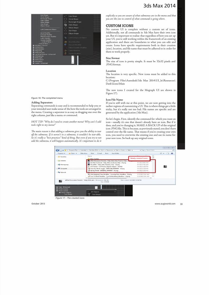
8122019 augi world 2013 10
httpslidepdfcomreaderfullaugi-world-2013-10 3352October 2013 wwwaugiworldcom
3ds Max 2014
Adding SeparatorsSeparating commands is easy and is recommended to help you oryour intended user make sense of the how the tools are arranged inthe menu Creating a separator is as easy as dragging one over theright column just like a menu or command
HO IP ldquoWhy do I need to create another menu Why canrsquot I addtools right to my menurdquo
Te main reason is that adding a submenu gives you the ability to tearoff the submenu If it werenrsquot in a submenu it wouldnrsquot be tear-ableSo itrsquos really a ldquobest practicesrdquo kind of thing But even if you try to notadd the submenu it will happen automatically Itrsquos important to do it
explicitly so you are aware of what submenus are in the menu and that you are the one in control of what command is going where
CUSTOM ICONSNo custom UI is complete without a custom set of iconsAdditionally not all commands in 3ds Max have their own iconyet But itrsquos important to realize that regardless of how you set up
your UI yoursquore still working within the framework of an existingapplication and there are boundaries to what you can edit andcreate Icons have specific requirements both in their creation(size) location and file name that must be adhered to in order forthem to work properly
SizeformatTe size of icon is pretty simple It must be 32x32 pixels andPNG format
LocationTe location is very specific New icons must be added to thislocation
CProgram FilesAutodesk3ds Max 2014UI_lnResourcesDarkIconsMain
Te new icons I created for the Mograph UI are shown inFigure 17)
Icon File NameIf yoursquore still with me at this point we are now getting into thenether regions of customizing a UI Tis is where things get a littletricky but itrsquos really not too bad File names are specific and aregenerated by the application (3ds Max)
So letrsquos begin First identify the command for which you want aniconmdashusually itrsquos one that doesnrsquot already have an icon But if itdoes and yoursquore changing it MAKE A BACK UP of the originalicon PNG file Tis is because as previously stated you donrsquot havecontrol over the file name Tat means if yoursquore creating your ownicon you need to overwrite the existing one and use its name foryour new icon So back up any original icons
Figure 16 The completed menu
Figure 17 ndash The created icons
8122019 augi world 2013 10
httpslidepdfcomreaderfullaugi-world-2013-10 3452wwwaugicom October 20
3ds Max 2014
PRO
DUCT
FOCUS
It really doesnrsquot matter whether you make the icon first or not ofind the name you need to use you need to navigate as follows
NOE Yoursquore about to edit the ribbon Tere is no need to save thesechanges as we are merely extracting information from it But if yoursquoredoing a lot of custom icon work you may want to save this change to theribbon so you can come back and continue your work in later sessionswithout have to recreate this every time just to get the proper file nameSaving this ribbon is not related to saving your default state of yourUI When yoursquore done creating all your UI icons you can just delete
whatever changes you make to the ribbon
1) Open the ldquoCustomize Ribbonrdquo dialog box
2) Create a new ldquotabrdquo by dragging it onto the ldquoExisting Ucolumn in the middle (see Figure 18)
3) Using the same drag method add a new ldquopanelrdquo to ttemp tab (Figure 19)
4) Now you can get the information you need Find tcommand for which you are creating an icon and dragto the panel
5) Locate the ldquoinfordquo portion of the ldquoPreview Windocolumn At the bottom of the column is the file namneeded to have the icon used properly by the applicati(Figure 20)
CONCLUSIONSo now you know how to create a custom UI scheme f3ds Max 2014 and up By using the Enhanced UI me
system itrsquos really easy to generate a multitude of workspathat allow Max to work the way you want to work
Te example used in this article was the ldquoMographrdquo UI thI created for NAB 2013 If you would like to downloand install it you can get it from my ldquoPinning the Stacblog on the Area herehttpareaautodeskcomblogschrismurray
Enjoy
Chris Murray works for Autodesk
Media amp Entertainment He istrained as an animator (3D variety)but considers himself a creative tech-nologist His daily role is a technicalldquoevangelistrdquo for Autodesk creating marketing deliverables for 3ds Max Heis the author of Mastering 3D StudioMax He has a Masters in Fine Arts(MFA) in Computer Animation fromMiami International University of Artand Design Follow him on witterchrismmurray
Figure 18 Creating a tab on the ribbon
Figure 19 Adding a panel to the tab
Figure 20 Finding the required file name
8122019 augi world 2013 10
httpslidepdfcomreaderfullaugi-world-2013-10 3552
AUGIMembersReach Higherwith ExpandedBenefitsAUGI is introducing three new Membership levelsthat will bring you more benefits than ever beforeEach level will bring you more content and expertiseto share with fellow members plus provide anexpanded more interactive website publicationaccess and much more
MEMBERMEMBER MEMBER
Basic members haveaccess tobull Forums
bullHotNews (last 12 months)
bull AUGIWorld (last 12 months)
DUES Free
Premier members haveaccess tobull Forums
bullHotNews (last 24 months)
bull AUGIWorld (last 24 months)
DUES $25
Professional members haveaccess tobull Forums
bullHotNews (full access)
bull AUGIWorld (full access and in print)
bull ADN 2013 Standard Membership Offer
DUES $100
Are you ready to upgrade yourself and your membership
Access additional benefits and upgrade at wwwaugicom
8122019 augi world 2013 10
httpslidepdfcomreaderfullaugi-world-2013-10 3652wwwaugicom October 20
AutoCAD MEP 2013
PRO
DUCT
FOCUS
by Vladimir Triantafillid
BIM IsWhatrsquos
Driving theIndustry
For the past decade many would arguethat building information modeling(BIM) has metastasized aggressivelythroughout the AEC industry but what
does BIM really mean More importantly whatdoes it do for us and for our industry Ask someone who hasbeen in this industry for more than 25 years or those nearingretirement and yoursquoll find that less than half see its value muchless care to make the effort with its implementation hesequestions mean something different for those who have beenin the industry the past 10-15 years Recent college graduates
however with their tech-savvy capacity and high expectationare eager to implement anything that resembles cutting-edgflashy technology ypical ly they are the ones most receptivenot adamant about putting their talents to use through BIM
I recently gave a BIM presentation with an emphasis on mchanical systems to the summer interns and new hires our companymdashall were non-BIM users except for onemdashbmy presentation did little justice to BIM Half of my audence had found a cure for their insomnia when they realizthis wasnrsquot the latest edition of ldquoCall of Dutyrdquo hat was n
8122019 augi world 2013 10
httpslidepdfcomreaderfullaugi-world-2013-10 3752October 2013 wwwaugiworldcom
AutoCAD MEP 2013
reflection on BIM by any measure Simply put I fell shortof connecting with a potentially captive audience eager toknow what really makes BIM intriguing or how it wouldgive them an edge in the industry I didnrsquot think to look pastpresenting the facts of its processes and benefits o simplyhave stated that proficiency in any of its many facets willpromote a lucrative career would give those still awake theimpetus to jump ship In hindsight the first step I shouldhave taken to begin this presentation was to ask what theywanted to get out of BIM
If you think itrsquos hard conveying the value and splendor ofBIM to receptive and impressionable young minds try toconvince the weathered veterans dead-set in their ldquooldtricksrdquo For every experienced veteran who has converted toBIM there are two ldquoold dogsrdquo that canrsquot shake ldquothe good olrsquodays when we used vellum and light tablesrdquo Guess whatmdashanincreasing amount of naysayers are starting to come aroundincluding those who say theyrsquove been burned by BIM in thepast hey are seeing the simple solutions BIM presents and
how these solutions translate into cost savings More andmore of those who had formerly questioned BIMrsquos utility areconvinced when installation efficiencies are not only real-ized but quantified
Another factor in the evolution of BIM is its tendency toexpand faster than the pace of its general population of us-ers hose of us proud to be catching up to what we think iscutting edge quickly realize it was just another false sense ofaccomplishment as BIMrsquos web continues to grow exponen-tially he solution is rather simple Focus on what you canhandle and always have the presence of mind and sense ofcaution to avoid being overwhelmed by the wake of BIMrsquos
progress herersquos plenty of money to be made and countlessfacets to explore as long we have the following mentality Welive in the information age and those wi lling to share knowl-edge will reap the rewards of communal synergy
On the opposite end of the spectrum you might find ourindustryrsquos opportunists In a hurried frenzy to claim theirspot in the intellectual property queue these opportunistsget carried away with pioneering what they assume is the lat-est improvements to BIM Instead of stopping to absorb anddevelop the benefits of 4D 5D 6D and so on the pioneersare spreading these ldquoDsrdquo thin with abandon further expand-
ing the gap between quality and quantity None of this i s tosay that wersquore heading in the wrong direction On the con-trary letrsquos call it more of a positive economic problemmdashthedemand for BIM expertise and development outweighs thesupply of available users
Fortunately as collegiate curricula catch on to this industrytrend the point of equilibrium will soon follow For as longas I can remember respective companiesrsquo 2D CAD depart-ments have been a significant source as the breeding groundfor potential BIM users While this route hasnrsquot changedregarding the career path of a draftsperson the source poolhas expanded to include architects engineers and construc-
tion managers just to name a few Itrsquos even hard not to noticeits stark demand when BIM and Revit courses are being in-creasingly offered at local community colleges I knew thenthat you didnrsquot necessarily need an undergraduate degreeback when I got my foot in the door of this industry hisprobably wonrsquot hold true in the coming years Still the privi-leged few who are already a part of this industry subset canrely on their experience in this fast-paced market to con-tinue to propel their careers forward ever faster All thesefew need to do is grab onto a small piece of BIMrsquos wing andhang on tight for the ride he fresh-out-of-college e ntrantsmight have a harder time grabbing onto this wing thatrsquos al-ready in motion
o those who are only vaguely famili ar with BIM it is typi-cally perceived as the equivalent of a 3D role-playing videogame In this case itrsquos not difficult to capture a ldquosnapshotrdquoimage of a 3D model shadows cast across random metal ob-
jects taking up space in an orderly fashion between ceil ingspaces and walls What is difficult is conveying the abun-dance of value behind the pretty picture to a client whorsquosonly interested in the pretty picture Who isnrsquot familiar withthe adage ldquoa picture is worth a thousand wordsrdquo Why notchange that saying to ldquoa BIM model is worth five thousandhyperlinksrdquo Now wersquore talking lifec ycles and facilities man-
More and moreof those who had
formerly questioned
BIMrsquos utilityare convinced
when installationefficiencies are notonly realized but
quantified
8122019 augi world 2013 10
httpslidepdfcomreaderfullaugi-world-2013-10 3852wwwaugicom October 20
AutoCAD MEP 2013
PRO
DUCT
FOCUS
agement his supposed video game has suddenly becomean encyclopedia of usable information But wait itrsquos not juststatic information thatrsquos stuck on a DVD on a shelf i n someownerrsquos random storage closet It has now become a livingdynamic source of real-time data Maintenance technicianswill know exactly where to go when the active 3D modelloaded on their laptop highlights a hot water pump needingservice while concurrently bringing up the cut sheets andoperation and maintenance manuals specific to that pumpor system Better still the source of information has shiftedfrom multiple stacks of large drawing sets collecting dust toseveral hundred gigabytes on a hard drive Yes Mrs Clientyour 3D BIM model will be usable for the next 20+ years
Even though you might not necessarily think about i t someof you probably realize that BIM has become the ldquomiddle-manrdquo for so many key components in the construction cyclewell beyond its intermediary role between design and con-struction phases You want to do some significant tenantimprovement in an existing building Laser-scan the exist-ing conditions hatrsquos BIM Is the general contractor rackingtheir brain trying to f igure out where to station the crane forthe project or pave the pathways for delivery trucks Nowtheyrsquore looking to BIM to answer these questions and opti-mize their decisions o take it a step further at which endof the building do we want to load thousands and thousands
of pounds of sheet metal and pipe And then which tradesshould be installing their systems first in any given area ofthe building hatrsquos right wersquore deriving sequencing andtimelines from the BIM model to e stablish the best routes totake while addressing any constructability issues BIM hasbecome the consultant that wears most of the hats Itrsquos ourone-stop shop
I know that Irsquove personified BIM as if itrsquos the brains behindall of its success Letrsquos take a moment to focus instead on itscollaborators or the sum of its integral parts to show thatin reality we are Dr Frankenstein and BIM is our monster
Except in our ca se wersquore beginning to ta me our monster anthose who were previously frightened by it are starting to sthat it indeed is no monster In fact while evolving to domdashand becomemdashgreater things BIM is transforming into aindustry hero he point of convergence is approaching bcause wersquore saving money time and even trees Soon enougBIM will be the industry standard even on the smaller proects Letrsquos keep the pedal to the meta l
You want to know the best news Most of us havenrsquot evebegun to scratch the surface of BIM but wersquore in strategpositions to reap the rewards aking the possibility of ivast potential into account isnrsquot it reassuring knowing th
in these tough economic times wersquore engaged in an industthat has a shortage of well-qualified BIM experts Our eposure alone sets us up for success Now ask yourselves thquestion Is BIM driving our industry or is it the BIM use
Vladimir riantafillidis works for aleading mechanical contractor in theSan Francisco Bay Area with morethan 10 years of experience in the in-dustry Although he has a bachelorrsquosdegree in biology his unique careerchoices have firmly rooted him in a
substantial BIM role awarding himthe opportunity of progressing along-side the relentless evolution of BIMOutside of his career hersquos always opento new adventures whether trying anew cuisine exotic travels or extremesports Te latter adventures have re-cently subsided as the balance of lifehas shifted his focus on spending timewith his growing family
You want to know the best news Most of us havenrsquot
even begun to scratch the surface of BIM but wersquore
in strategic positions to reap the rewards
8122019 augi world 2013 10
httpslidepdfcomreaderfullaugi-world-2013-10 3952
8122019 augi world 2013 10
httpslidepdfcomreaderfullaugi-world-2013-10 4052wwwaugicom October 20
Revit Structure 2014
PRO
DUCT
FOCUS
Streamlining
Sheet Listswith a Custom
Application
In this article we take a brief look a simpleadd-in for Autodeskreg Revitreg named X-Sheetswhich provides tools for incorporating sheetsfrom an AutoCADreg sheet set in a Revit sheet
list ypically this is handled by manually addingplaceholder sheets to the Revit sheet list Tis can be problematicbecause the sheet list becomes disconnected from the sourceand must be updated manually With X-Sheets sheet set datais exported directly from AutoCAD linked to a Revit project
and included in the sheet list by automatically addingupdatinplaceholder sheets For this example all structural scheduleplans elevations and section sheets are in Revit Structure Adetail sheets will be pulled from an external AutoCAD sheet set
X-SHEETS RIBBON PANEL Te first command on our ribbon panel is Discipline Tcommand is used to establish the Revit project parameter twhich the AutoCAD sheet subsets will be mapped For th
by Jonathan Albe
Figure 1 Revit X-Sheets ribbon panel
8122019 augi world 2013 10
httpslidepdfcomreaderfullaugi-world-2013-10 4152October 2013 wwwaugiworldcom
Revit Structure 2014
example we have created a project parameter named My DisciplineParameter Each Revit Structural sheet has been assigned a valueof SRUCURALmdashthe same as the subset name for theAutoCAD detail sheets Te sheet list is grouped and sorted bythis parameter
Te next command on the ribbon panel is Links Tis command isused to establish a link between the Revit project and XML file(s)
containing sheet information exported from AutoCAD You cancreate as many links as needed and use relative paths if required
Te next two commands Sheets and Update do the work ofaddingupdating placeholder sheets to the sheet list While theSheets command allows you to select individual sheets from linksto include in the sheet list the Update command includes all sheetsfrom all links
EXPORT SHEETS FROM AUTOCADFigure 3 shows the AutoCAD X-Sheets ribbon panel and asample sheet set containing structural detail sheets Notice thedetail sheets are grouped under a subset named SRUCURALTis subset name can be exported with each sheet and mapped to
the My Discipline Parameter in Revit Figure 3 shows the ExportSheets dialog with an option to include subset information and theability to exclude individual sheets Selecting the Export buttonprompts us with a dialog to save an XML file to be linked into ourRevit project
Figure 2 Discipline command dialog
Figure 3 AutoCAD X-Sheets ribbon panel and sample sheet set
Figure 4 Export sheets dialog
Figure 5 Export complete
8122019 augi world 2013 10
httpslidepdfcomreaderfullaugi-world-2013-10 4252wwwaugicom October 20
Revit Structure 2014
PRO
DUCT
FOCUS
ESTABLISH LINK TO XML FILE IN REVIT
PROJECTFigure 6 shows the Manage Links dialog A link has been added tothe XML file we generated when exporting sheets from AutoCADNotice there is an option to make the link path relative to our
Revit Project location
IMPORT SHEETS FROM XML LINKFigure 7 shows the Revit Structure sheet list before any sheetshave been imported from AutoCAD After selecting the Sheetscommand we are prompted with a Manage Sheets dialog
For this example we have selected all sheets from the XML linto include in our sheet list After confirming the dialog neplaceholder sheets are immediately added to the sheet list angrouped according to the SubsetDiscipline mapping Te neplaceholder sheets are identified behind the scenes as being relatto the X-Sheets XML link for later updating
Figure 6 Manage Links dialog
Figure 9 Sheet list after import
Figure 7 Sheet list before import
Figure 8 Manage Sheets dialog
The X-Sheets
add-in is a great tool
for incorporating
AutoCAD sheets into
a Revit sheet list
8122019 augi world 2013 10
httpslidepdfcomreaderfullaugi-world-2013-10 4352October 2013 wwwaugiworldcom
Revit Structure 2014
UPDATE SHEETSFigure 10 shows the Export Sheets dialog in AutoCAD afterdetail sheets have been renumbered to include ldquo-Ardquo When changesare made to AutoCAD sheets the original export steps must befollowed to replace the XML file linked to our Revit project Oncethe XML has been replaced simply run the Update command inRevit to update the sheet list
SUMMARYTe X-Sheets add-in is a great tool for incorporating AutoCADsheets into a Revit sheet list Te add-in saves time by automatically
adding placeholder sheets eliminates room for error in manualtranslation and helps to keep your sheet list up to date withminimal effort
Jonathan Albert is co-founder of BIM- pulse echnologies LLC amp SeniorApplications Developer at LindemanBentzon Bojack Engineering in Cler-mont Florida He has worked morethan 15 years implementing and usingBIM echnology for some of the na-tionrsquos leading production home build-
ers Most recently he has developedBIMpulse an Options Managementand Material akeoff Add-In for Au-toCAD Architecture Revit and Au-todesk Design Review Jonathan can bereached at jonalbbecom
Figure 10 Export Sheets dialog after sheet renumber
Figure 11 Update complete
Figure 12 Sheet list after update
The X-Sheets
add-in is agreat tool for
incorporatingAutoCAD
sheets intoa Revit
sheet list
8122019 augi world 2013 10
httpslidepdfcomreaderfullaugi-world-2013-10 4452wwwaugicom October 20
AutoCAD Civil 3D 2014
PRO
DUCT
FOCUS
by Tench Tilghma
Itrsquos a fact Jack You invested money in the worldrsquosmost popular civil engineering and designsoftware You (or someone else) will have workhard to make the software run productively
and publish the engineering design or surveywork acceptably
Every AutoCADreg Civil 3Dreg user will tell you ldquoYou need a Civil3D templaterdquo
heyrsquore right sort of You need more than one he suppliedexample Autodesk template files (dwt) are just thatmdashexamplesto show you that things are possible A great many ldquothingsrdquo arepossible in Civil 3D It is data-centric model-based software Asa dedicated content developer and continuous customizer of Civil3D I hope the following perspectives and tips help shorten thecycles and reduce the pain of customizing the software
AutoCAD Civil 3D was constructed from the ground up todisconnect the survey and engineering data from how that missioncritical data is represented
WITH LIBERTY COMES RESPONSIBILITYAs far as Autodesk is concerned what you want the many Civil 3Dldquothingsrdquo to look like and how the Civil 3D data is to be annotated istotally up to you hatrsquos not really true is it Plan sets are publishedin arcane symbolic graphic languages designed to faithfully conveythe design intent to someone who must build it with a plan checkeror two (or three or four) stuck in between
As a professional I prefer to call them ldquoPlan Set Languagesrdquo hhelps focus the development to the publishing of Civil 3D datMost people throw a fuzzy word around this complex mix human perceptive agendas and call that ldquoCAD Standardsrdquo
ldquohe wonderful thing about standards is there are so many of themndash Grace Hopper et al
PICK A STANDARD AND MANAGE BY ITldquoWe already have a CAD standardrdquo his may be the first anworst Civil 3D customization mistake any skilled AutoCAD usor organization can make he odds are the CAD standards yoemployed before do not take into account the data centric anmodel-based methods that Civil 3D employs Simply put Civ3D manages how things look and behave by Style Primitive-basAutoCADreg standards may get in the way
Older ldquoCADrdquo standards by definition must be focused on CAprimitive publishing specifics layer textstyle (height) blo
CustomizeCorrectly
Figure 1 Standards documentation is required
8122019 augi world 2013 10
httpslidepdfcomreaderfullaugi-world-2013-10 4552October 2013 wwwaugiworldcom
AutoCAD Civil 3D 2014
graphics standards and so on In raw AutoCAD and AutoCAD-based drafting and design software the only way to manage all theCAD primitive stuff was to be SPECIFIC about all the details allthe time he drawing we create and check things in is the drawingwe publish
If you publish work out of quality control or design drawingsin Civil 3D this is a sign you may be missing some of its timesaving advantages
While the old CADD process works it requires a lot of man-hoursdedicated to maintaining and checking the details Clearly one ofCivil 3Drsquos critical design development goals is to rid organizationsand Civil 3D users of this expensive man-hour burden and costhe idea here is to put the man-hours into the iterative engineeringprocess instead Civil 3D Feature data and Style make this possible
Civil 3D styles and label styles do employ the AutoCAD layertextstyle block references AutoCAD customizers are used tohe software is still called ldquoAutoCADrdquo Civil 3D after all Our
AutoCAD customization skills still apply But we must applythem differently and much more systematically Herersquos whyhellip
YOU NAME ITmdashTHE MOST CRITICAL
STANDARDCivil 3D Styles and label styles employ (reference) the AutoCADldquonamedrdquo parts to ldquoexpressrdquo themselves Style tools just look for andmatch the ldquorightrdquo names Change the ldquomeaningrdquo andor definitionof the names and you can change anything
We call this fundamental property and benefit of object-orientedprogramming the Power of Names In programming speak this
concept and practical reality is called a ldquonamespacerdquo
Such a namespace in engineering speak answers the questionldquoIn this context does ldquoDIrdquo means a ldquodrop inletrdquo In a minute wersquollget to the structure of a customization ldquonamespacerdquo for Civil 3DAutoCAD references
THE POWER OF NAMESGo ahead and make a drawing from your current Civil 3D templateoss in some Civil 3D data by data reference from any projectUse the RENAME command on any of the old AutoCAD stylecollectionsmdashtry layers
Rename like crazy Your existing Civil 3D styles and label styles willhappily work exactly the same he components in the Civil3DFeature and Label Styles will go to your renamed layers Becauseyou didnrsquot change the properties of the layers either nothingchanges Itrsquos not too exciting until you think about what it means
FOLLOW A SCRIPTObviously as customizers we never want to do this sort of workmanually Computers are faster better and more exact typists thanwe are We commonly rely on AutoCAD scripts generated from
Microsoft Excel spreadsheets (See the end of the article)
here are a couple of key collections in the object model thatCivil 3D walls off from this form of potentially destructiveuser madnessmdashObject Properties in Drawing Settings and afew things like Figure Prefix Dbs values that are not ever in thedrawing per se
WHAT REALLY MATTERSAutoCAD Civil 3D style is mind-boggling abstraction Everythingis designed and built to point at references We can employ styleabstraction for our benefit
In one sense AutoCAD Civil 3D style doesnrsquot care aboutAutoCAD layer standards block libraries textstyles colorsplotstyles or really anything else AutoCAD From our perspectiveall the Civil 3D styles care about are the arbitrary and exact namesthey currently reference
he Civil 3D customizerrsquos dilemma Keep book on the exactnames here are a lot of names to keep track of You must havea plan You must have rules You must employ the same processesconsistently in the same order to get quality assured results
Figure 2 Are description keys a namespace
Figure 3 Rename the AutoCAD reference names
8122019 augi world 2013 10
httpslidepdfcomreaderfullaugi-world-2013-10 4652wwwaugicom October 20
AutoCAD Civil 3D 2014
PRO
DUCT
FOCUS
hat Current word is a wonderfully relative term forthe customizer
Build a set of styles extract them to another drawing rename andor redefine the references and quickly produce a different resulthe Current method makes it easy to propagate success andmistake It makes it repetitively tedious to make fixes
NO CAN STOPAs innovative content developers for Civil 3D we chose to employthe National CAD Standard (NCS) as our fundamental Namestandard Not because we like the NCS but because of all thehard-won experience expressed in these tested standards Inmany respects we employ the NCS UDS (Uniform DrawingStandards) etc in our Production Solution products becauseof the underlying How and Why for those standards and theirpractical published Rules
We want to build faster high-performance vehicles Why reinventthe wheel when we can improve on it
STANDARD KEYS TO NAMEShe NCS employs a hierarchical concept of Keys here areMajor Keys Minor Keys etc that have order precedence and aninterpreted meaning he NCS Layer standard employs the Key-based rules to produce defined meanings to Layers
You can in practice employ the same Layer Keys to be genericor granularly specific about where the published results go Allthe annotation can go to one layer or many different layers forexample Styles andor sets do the work
his KEY CODE structure produces a flexible and structuredldquonamespacerdquo we referred to earlier Itrsquos a namespace that both thesoftware can employ and is relatively easy for us dumb-bunnyhumans to learn to decode when we must Most of the time theusers donrsquot and shouldnrsquot care anyway
Figure 4 shows a few of the NCS ldquolikerdquo Keys we employ in ourproducts We employ them for both layer and block collectionsand even the structure of libraries hey may even be employedin Civil 3D style names when thatrsquos appropriate (See the endof the article)
he customizing key point is that the meanings of these specificKeys can be translated into any other set (or sets) of different
Keys he Key changes can be systematically applied to whatevAutoCAD reference tables and resources we require
he results of any changes will float uphill to the named Civil 3Styles we choose to employ hink of all the AutoCAD referencin a template as a Set
BEYOND AUTOCADNow wersquove looped back to Civil 3D style tools and substantivetheir names and what their parts refer to Welcome to the circuland iterative world that is customizing and employing Civil 3D
Aside from the requisite customization skills and experience build style tools our practical biggest customization issues afrankly Civil 3D human interface issues
No matter how you cut it you have a very limited amount of tespace to help users decide on the ldquorightrdquo style tool to use he teof the style toolrsquos name is all you get to deliver to the user ypicaitrsquos a pick box list
You might get lucky and have the Style Viewer but that Viewcannot represent everything a style can do
FEATURE STYLES NAMESWhat we call the ldquoFeature Stylesrdquo (the Ci3D Featurersquos graphics) require that our stynames explain in simple readable humterms what the tool does For examplesurface style like ldquoContours 1-5 Proposed
Figure 4 Some standard keys
Figure 5 The limitations of user style choice
8122019 augi world 2013 10
httpslidepdfcomreaderfullaugi-world-2013-10 4752October 2013 wwwaugiworldcom
AutoCAD Civil 3D 2014
For the common and most understood features this makes somesense ASCII order rules how named Styles organize Names mustsort that out
Complex graphic features such as Views have a lot more going onldquoMy Standard Profile Viewrdquo doesnrsquot cut it except in a publishingtemplate he style names must be more informative and specificDoes the Profile View include grid lines or not We must recognizethat the engineering data behind what we want to visualize isvariable and the user will have specific needs to get work doneWhen you check a surface you need to see the data in differentways than when the result is published
Choice of style is productive Choice is not contrary to publishingstandards unless you mix the two
LABEL STYLE NAME FACTORSWhen we open the Alignment Label Style collection andorstart to assemble Sets of Label Styles we see any hope of namesimplicity for label styles disappears in a flash
he majority of styles are annotative here are a lot of formsand specific types of them Label Style ype matters he smartcustomizer employs the Label Style Default (LSD) hierarchyexpressed in the oolspacegtgtSettings tab or ignores it and missesthe benefits
Label styles often must have a geometric framework to themItrsquos about ldquoreadabilityrdquo and meaning Whether this label goes upor down or attaches here and not there is critical to annotativeclarity he graphic structure of many data-rich label styles alsofundamentally matters to the stylersquos upgrade stability herersquos
a maintenance cost to pay if you refuse to employ consistentgeometric structures in label styles
CUSTOM USAGECan users see the right data and at the right time Will the useremploy a general alignment parcel or figure line and curve labelHow do they see the difference in a simple list It is easy to misshow ldquoon-the-flyrdquo annotative information negatively or positivelyeffects design time decision making and quality control Peoplewill make things to get the job done Do you fight it or enable ithe Simple Style Rules anyone can learn
THE CIVIL 3D NAMESPACESA Civil 3D style naming convention must be human readablecreate order in the interface and therefore include a rule-basedeasy-to-learn code system that expresses quickly the critical detailso customize we need two namespaces One for the top-end stylesand one for the back-end AutoCAD references In productionprojects we need a third namespace for how we name the featuresbut thatrsquos another story
his client and this project demand these CAD standards specificsAnother client and project demand something different Even ifyou donrsquot believe you regularly face that common problem you
still have to improve the internal production templates themselveshe method and process arenrsquot different
In our project-based production world Civil 3D users andsupervisory staff can always work with the familiar and publishwhat is demanded in a customized publishing template hetwo-pronged project template approach has the added benefit ofpotentially quantifying the costs and real return on investment forthe customization itself
CUSTOMIZE TO PUBLISH ON DEMANDIn practical terms we can change the expressed graphicsmdashthe PlanSet Language (CAD standards) with managed intern level staffEven non-CAD people can see and identify graphic differenceOnly basic AutoCAD and basic spreadsheets skills are requiredfor much of the work if you have a naming plan ldquoChange thatmanhole block to look like this manhole blockrdquo Your ldquothatrdquo mustbe specific
ldquoPublish on demandrdquo capability is a productivity and competitive
advantage but it takes repetitions to develop and practice the skillsWe must endlessly customize Civil 3Dmdashreap the benefits
CIVIL 3D NAME RESOURCEShe Standard Keys the NCS-like AutoCAD reference namespacehe Jump Standards includes the detailed and documented stylenamespace Find them at wwwcadpilotcomresourcesaspx
Excel Cell Formula Script ExampleHerersquos the pseudo code for a typical formula-based layer script thatmakes a layer table with all the details filled in from a cell It createsa series of quote wrapped strings when a column of such cells is
copied and pasted to an ASCII text file
ltLayerCommandgtampCHAR(13)amprdquoSrdquoampCHAR(13)ampltOldLayergtampCHAR(13)amprdquoRrdquoampCHAR(13)ampltNewLayergtampCHAR(13)ampltNewLayergtampCHAR(13)amprdquoCrdquoampCHAR(13)ampltColorgtampCHAR(13)ampCHAR(13)amprdquoLWrdquoampCHAR(13)ampltLineweightgtampCHAR(13)ampCHAR(13)amprdquoPSrdquoampCHAR(13)ampltPlotstylegtampCHAR(13)ampCHAR(13)amprdquoDrdquoampCHAR(13)ampltDescriptiongtampCHAR(13)ampltNewLayergtampCHAR(13)
ench ilghman is President ofMoreCompetency Inc an Autodesk
Developer Partner specializing in in-novative Civil 3D Production Solu-tion products and consulting services
for AutoCAD Civil 3D ench is aregular speaker at Autodesk Univer-sity and AEC industry events on thetopics of technology adoption innova-tion and (his personal favorite) peopleskills He posts on the Get the Jump onCivil 3D blog
8122019 augi world 2013 10
httpslidepdfcomreaderfullaugi-world-2013-10 4852wwwaugicom October 20
Revit MEP 2014
PRO
DUCT
FOCUS
by Todd Shackelfor
W
hen any new technology hits theground there are plenty of false startsand backtracking In time shortcutsare found tricks of the trade are
discovered and best practices are defined So is thecase with Autodeskreg Revitreg even for MEP users his article willoutline a logical roadmap of technical and non-technical mustdorsquos and donrsquot dorsquos for transitioning to Revit MEP From settingexpectations defining goals and plotting in Revit to addressingBIM IPD and VDC the checklist of elements required to helpRevit really work in an office will be covered Every implementationwill come with resistance workflow issues and plenty of headachesbut staying on course and hitting the important milestones alongthe way will help reduce stress of something akin to the craziestfamily trip ever
FIRST CONSIDERATIONS ndash SOFTWAREOne might think it is all about Revit he truth is that Revit reallywants to act as a central location for data that is constantly on themove Much like a smartphone leverages the power of thousandsof applications Revit plugs into workflows with more than a fewAutodesk programs as well as a host of third-party programs hesimple fact that the Building Design Suite comes with so manyvaried applications is a pretty big hint that Revit wants to play ona team Firms need to look at their processes from a high level andlook for the best workflows and programs for the team
FIRST CONSIDERATIONS ndash HARDWAREEvaluate the PCs and know what their capabilities are anknow what Revit requires Search Autodeskrsquos website for systerequirements for Revit products Requirements for three tieof deployment are listed for systems covering an entry-levconfiguration a balanced performance configuration and performance configuration Certified and supported graphi
hardware is also accessible from this page he non-hardwasavvy should seek input from an I professional Revit cannand will not perform on outdated or entry-level PCs and thperson leading the implementation usually takes the blame wheexpectations fall short Best advice is overkill it on hardware Whseems over the top today is inadequate in a year
FIRST CONSIDERATIONS ndash TRAININGhere is no way to get around the fact that training will need tbe done Even if every person in the firm has already used Revtraining on using Revit company standards must still take plachere are many ways to deliver training An in-house expe
TransitionRoadmap
8122019 augi world 2013 10
httpslidepdfcomreaderfullaugi-world-2013-10 4952October 2013 wwwaugiworldcom
Revit MEP 2014
can provide just-in-time all the time Autodesk resellers andconsultants typically provide three- to five-day immersion trainingand short- to long-term consulting here are countless web-based training optionsmdashfree and paid Community colleges thatoffer Revit training usually require a final project that will putstudents through the paces and better entrench the
knowledge and skills
On the down side Revit MEP-specific classes areall but impossible to find Lastly the extreme go-getter can buy a book and learn on the job In realityeveryone learns differently and being preparedto leverage all these types of training is the bestsolution People will gravitate to the solution thatworks best for them when it is provided
FIRST CONSIDERATIONS ndash
LINE UP YOUR DUCTS (UGH hellip
DUCKS)Set appropriate goals based on the size of thefirm Small medium and large firms will havedrastically different goals and timelines It mightseem odd but small firms have the upper hand inadopting new technologies and processes hinkabout it What is easiermdashgetting 3 people toagree or 300 Recognize that an AE firm will havecompletely different goals and processes than a solely MEP firmDuring any shift in process be prepared to support the old andnew at the same time and sometimes in the same project hiswill mean keeping symbols in Revit as close as possible to symbols
in AutoCADreg Consider how quality reviews are done and clientexpectations When things look different it is an impediment tochange Minimizing the impediments will help tremendously
All that being said communication is the real key to most everyprojectrsquos success It is important keep information flowing upand down the chain and set the expectations early Some criticalexpectations for this type of implementation are that things will gowrong things will take longer things will look different things willhave to change and things will continue to evolve Remind usersand management of the progress they have been made by trackingand documenting incremental goals
With a general direction and expectations set itrsquos time to get morespecific about the journey his trip is a long one and a phasedapproach is best Firms can tailor the following phasing to suitindividual needs his example has four phasesmdasheach with itsown goals building off the previous phases
Phase 1 - Goals1 Create construction documents2 Improved collaboration3 Interference mitigationo obtain these goals the following Revit items need to be addressedhe first group addresses the goal of good construction documentshe second group deals with process and keeping things standardhe space available in this article doesnrsquot allow for ldquoHow torsquosrdquo foreach item but each is well documented in the Revit help pageand all over the Internet Get a couple points of view and marrythe possibilities to the culture and needs of the firm in question
bull Line styles createdbull Fonts set for plan text titles title blocks tags and everything
elsebull Object styles ndash Define the weight color tone and transparency
of everything bull Incorporation of standard detailsbull Browser organization ndash Decide how you want to see views
organizedbull Filters ndash Know if you need standard filters and create them
ahead of timebull Phasesbull View templatesbull Project templatebull Duct Stylesbull Pipe stylesbull Family creation
Figure 1
Figure 2
8122019 augi world 2013 10
httpslidepdfcomreaderfullaugi-world-2013-10 5052
8122019 augi world 2013 10
httpslidepdfcomreaderfullaugi-world-2013-10 5152October 2013 wwwaugiworldcom
Inside Track
CSCrsquos Integratorhttpwwwcscworldcom
Integrator is a tool that allows you to synchronize structural designscreated in CSCrsquos Fastrak Building Designer (steel building designsoftware) and Orion (structural concrete building design software)with Autodeskreg Revitreg 2014
ldquoLeading structural software provider CSC has released a new versionof Integrator its market leading Structural BIM integration softwarefor synchronizing code-compliant models produced in CSCrsquos buildingdesign software Fastrak and Orion with Autodeskreg Revitreg Nowfully compatible with Autodesk Revit 2014 structural engineers andtechnicians have even greater control during the integration process
Using Integrator full and part models can be synchronized betweenFastrak or Orion and Autodesk Revit with the ability to manageadded deleted and modified members and their associated
design datardquo
BiMTOOLShttpwwwsofistikcom
BiMOOLS is a set of productivity tools that are designed forAutodeskreg Revitreg 2014 Te plug-in can be installed from theAutodesk Exchange Apps store
ldquoTe first international version of the SOFiSiK BiMOOLS isnow available SOFiSiK BiMOOLS is a collection of free tools forAutodeskreg Revitreg Structure to enhance the productivity up to 50Te features range from easy font type substitution and automaticgeneration of dimensional lines over the automatic positioning ofstructural elements to the comprehensive Family Creator to generatefamilies of eg beams braces and columns for optimal communicationwith FE analysis tools like the SOFiSiK softwarerdquo
Find further information and download links for Revit 2012 and
2013 on the dedicated BiMOOLS website
Autodesk AutoCAD 360 21httpswwwautocad360com
Autodeskreg AutoCADreg 360 is a mobile and web-based application that allows you to view editand share drawing files created with AutoCADand AutoCAD-based products Te mobile appis available from the Apple iunes App Store andGoogle Play Store
ldquoAutoCAD 360 is a free easy-to-use drawing and drafting mobileapp that allows you to view edit and share AutoCAD drawingsmdashanytime anywhere Simplify site visits and fieldwork with powerfuldesign review and markup toolsmdashavailable online and offline
Seamlessly share drawings with others across desktop web andmobile devices Easily access drawings from web browsers using
the free companion AutoCAD 360 web app AutoCAD 360Pro subscription plans further expand the functionality of
the app bringing additional capabilities to the fieldrdquo
Te updates that are in this latest release arebull Stunning high-resolution drawings display
via full retina supportbull Better display through improved PDF
supportbull Easy switching between metric and imperial
unitsbull Saves time with faster app loading bull Improved collaboration through in-app
notifications and streamlined sharing bull New properties for Properties Palette
(Pro version)
AUGIWorldbrings
you recentdevelopmentsin Autodeskand AEC-relatedsoftwareitems
Until next issue
If you have some news to share with us for future issues please let usknow Likewise if you are a user of a featured product or news itemand would like to write a review we want to know
By Lee Ambrosius
8122019 augi world 2013 10
httpslidepdfcomreaderfullaugi-world-2013-10 5252
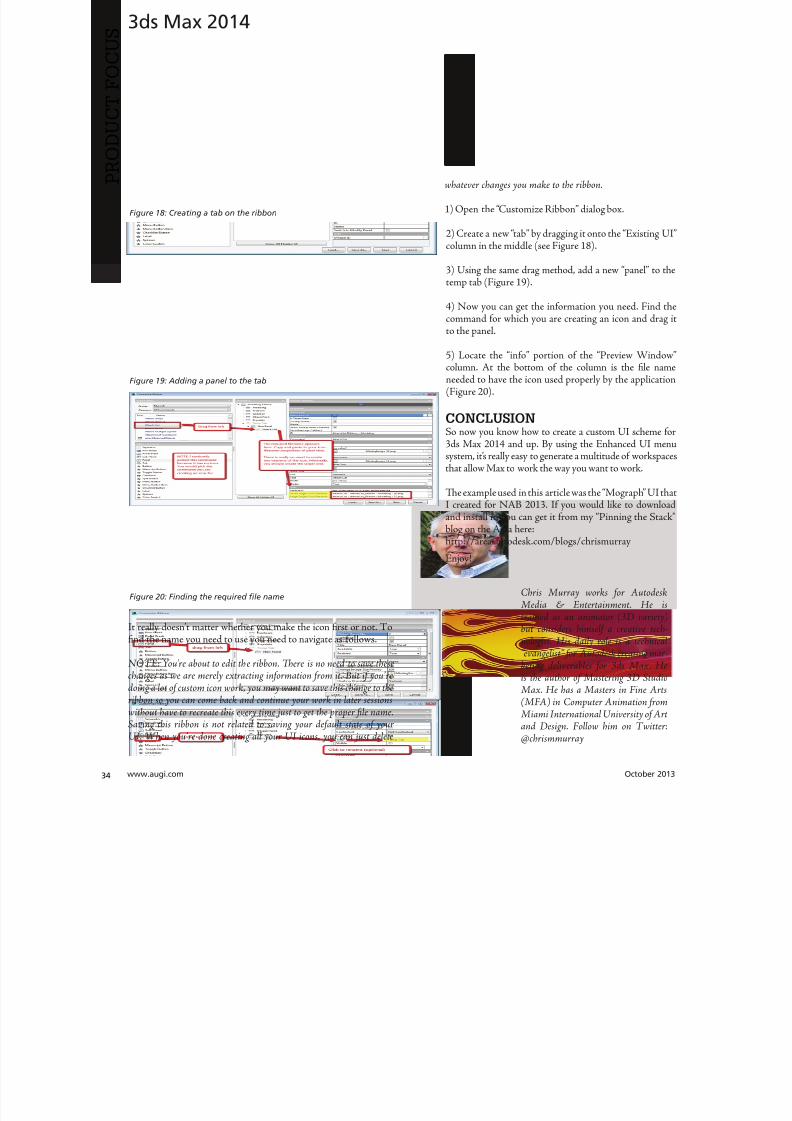
8122019 augi world 2013 10
httpslidepdfcomreaderfullaugi-world-2013-10 3652wwwaugicom October 20
AutoCAD MEP 2013
PRO
DUCT
FOCUS
by Vladimir Triantafillid
BIM IsWhatrsquos
Driving theIndustry
For the past decade many would arguethat building information modeling(BIM) has metastasized aggressivelythroughout the AEC industry but what
does BIM really mean More importantly whatdoes it do for us and for our industry Ask someone who hasbeen in this industry for more than 25 years or those nearingretirement and yoursquoll find that less than half see its value muchless care to make the effort with its implementation hesequestions mean something different for those who have beenin the industry the past 10-15 years Recent college graduates
however with their tech-savvy capacity and high expectationare eager to implement anything that resembles cutting-edgflashy technology ypical ly they are the ones most receptivenot adamant about putting their talents to use through BIM
I recently gave a BIM presentation with an emphasis on mchanical systems to the summer interns and new hires our companymdashall were non-BIM users except for onemdashbmy presentation did little justice to BIM Half of my audence had found a cure for their insomnia when they realizthis wasnrsquot the latest edition of ldquoCall of Dutyrdquo hat was n
8122019 augi world 2013 10
httpslidepdfcomreaderfullaugi-world-2013-10 3752October 2013 wwwaugiworldcom
AutoCAD MEP 2013
reflection on BIM by any measure Simply put I fell shortof connecting with a potentially captive audience eager toknow what really makes BIM intriguing or how it wouldgive them an edge in the industry I didnrsquot think to look pastpresenting the facts of its processes and benefits o simplyhave stated that proficiency in any of its many facets willpromote a lucrative career would give those still awake theimpetus to jump ship In hindsight the first step I shouldhave taken to begin this presentation was to ask what theywanted to get out of BIM
If you think itrsquos hard conveying the value and splendor ofBIM to receptive and impressionable young minds try toconvince the weathered veterans dead-set in their ldquooldtricksrdquo For every experienced veteran who has converted toBIM there are two ldquoold dogsrdquo that canrsquot shake ldquothe good olrsquodays when we used vellum and light tablesrdquo Guess whatmdashanincreasing amount of naysayers are starting to come aroundincluding those who say theyrsquove been burned by BIM in thepast hey are seeing the simple solutions BIM presents and
how these solutions translate into cost savings More andmore of those who had formerly questioned BIMrsquos utility areconvinced when installation efficiencies are not only real-ized but quantified
Another factor in the evolution of BIM is its tendency toexpand faster than the pace of its general population of us-ers hose of us proud to be catching up to what we think iscutting edge quickly realize it was just another false sense ofaccomplishment as BIMrsquos web continues to grow exponen-tially he solution is rather simple Focus on what you canhandle and always have the presence of mind and sense ofcaution to avoid being overwhelmed by the wake of BIMrsquos
progress herersquos plenty of money to be made and countlessfacets to explore as long we have the following mentality Welive in the information age and those wi lling to share knowl-edge will reap the rewards of communal synergy
On the opposite end of the spectrum you might find ourindustryrsquos opportunists In a hurried frenzy to claim theirspot in the intellectual property queue these opportunistsget carried away with pioneering what they assume is the lat-est improvements to BIM Instead of stopping to absorb anddevelop the benefits of 4D 5D 6D and so on the pioneersare spreading these ldquoDsrdquo thin with abandon further expand-
ing the gap between quality and quantity None of this i s tosay that wersquore heading in the wrong direction On the con-trary letrsquos call it more of a positive economic problemmdashthedemand for BIM expertise and development outweighs thesupply of available users
Fortunately as collegiate curricula catch on to this industrytrend the point of equilibrium will soon follow For as longas I can remember respective companiesrsquo 2D CAD depart-ments have been a significant source as the breeding groundfor potential BIM users While this route hasnrsquot changedregarding the career path of a draftsperson the source poolhas expanded to include architects engineers and construc-
tion managers just to name a few Itrsquos even hard not to noticeits stark demand when BIM and Revit courses are being in-creasingly offered at local community colleges I knew thenthat you didnrsquot necessarily need an undergraduate degreeback when I got my foot in the door of this industry hisprobably wonrsquot hold true in the coming years Still the privi-leged few who are already a part of this industry subset canrely on their experience in this fast-paced market to con-tinue to propel their careers forward ever faster All thesefew need to do is grab onto a small piece of BIMrsquos wing andhang on tight for the ride he fresh-out-of-college e ntrantsmight have a harder time grabbing onto this wing thatrsquos al-ready in motion
o those who are only vaguely famili ar with BIM it is typi-cally perceived as the equivalent of a 3D role-playing videogame In this case itrsquos not difficult to capture a ldquosnapshotrdquoimage of a 3D model shadows cast across random metal ob-
jects taking up space in an orderly fashion between ceil ingspaces and walls What is difficult is conveying the abun-dance of value behind the pretty picture to a client whorsquosonly interested in the pretty picture Who isnrsquot familiar withthe adage ldquoa picture is worth a thousand wordsrdquo Why notchange that saying to ldquoa BIM model is worth five thousandhyperlinksrdquo Now wersquore talking lifec ycles and facilities man-
More and moreof those who had
formerly questioned
BIMrsquos utilityare convinced
when installationefficiencies are notonly realized but
quantified
8122019 augi world 2013 10
httpslidepdfcomreaderfullaugi-world-2013-10 3852wwwaugicom October 20
AutoCAD MEP 2013
PRO
DUCT
FOCUS
agement his supposed video game has suddenly becomean encyclopedia of usable information But wait itrsquos not juststatic information thatrsquos stuck on a DVD on a shelf i n someownerrsquos random storage closet It has now become a livingdynamic source of real-time data Maintenance technicianswill know exactly where to go when the active 3D modelloaded on their laptop highlights a hot water pump needingservice while concurrently bringing up the cut sheets andoperation and maintenance manuals specific to that pumpor system Better still the source of information has shiftedfrom multiple stacks of large drawing sets collecting dust toseveral hundred gigabytes on a hard drive Yes Mrs Clientyour 3D BIM model will be usable for the next 20+ years
Even though you might not necessarily think about i t someof you probably realize that BIM has become the ldquomiddle-manrdquo for so many key components in the construction cyclewell beyond its intermediary role between design and con-struction phases You want to do some significant tenantimprovement in an existing building Laser-scan the exist-ing conditions hatrsquos BIM Is the general contractor rackingtheir brain trying to f igure out where to station the crane forthe project or pave the pathways for delivery trucks Nowtheyrsquore looking to BIM to answer these questions and opti-mize their decisions o take it a step further at which endof the building do we want to load thousands and thousands
of pounds of sheet metal and pipe And then which tradesshould be installing their systems first in any given area ofthe building hatrsquos right wersquore deriving sequencing andtimelines from the BIM model to e stablish the best routes totake while addressing any constructability issues BIM hasbecome the consultant that wears most of the hats Itrsquos ourone-stop shop
I know that Irsquove personified BIM as if itrsquos the brains behindall of its success Letrsquos take a moment to focus instead on itscollaborators or the sum of its integral parts to show thatin reality we are Dr Frankenstein and BIM is our monster
Except in our ca se wersquore beginning to ta me our monster anthose who were previously frightened by it are starting to sthat it indeed is no monster In fact while evolving to domdashand becomemdashgreater things BIM is transforming into aindustry hero he point of convergence is approaching bcause wersquore saving money time and even trees Soon enougBIM will be the industry standard even on the smaller proects Letrsquos keep the pedal to the meta l
You want to know the best news Most of us havenrsquot evebegun to scratch the surface of BIM but wersquore in strategpositions to reap the rewards aking the possibility of ivast potential into account isnrsquot it reassuring knowing th
in these tough economic times wersquore engaged in an industthat has a shortage of well-qualified BIM experts Our eposure alone sets us up for success Now ask yourselves thquestion Is BIM driving our industry or is it the BIM use
Vladimir riantafillidis works for aleading mechanical contractor in theSan Francisco Bay Area with morethan 10 years of experience in the in-dustry Although he has a bachelorrsquosdegree in biology his unique careerchoices have firmly rooted him in a
substantial BIM role awarding himthe opportunity of progressing along-side the relentless evolution of BIMOutside of his career hersquos always opento new adventures whether trying anew cuisine exotic travels or extremesports Te latter adventures have re-cently subsided as the balance of lifehas shifted his focus on spending timewith his growing family
You want to know the best news Most of us havenrsquot
even begun to scratch the surface of BIM but wersquore
in strategic positions to reap the rewards
8122019 augi world 2013 10
httpslidepdfcomreaderfullaugi-world-2013-10 3952
8122019 augi world 2013 10
httpslidepdfcomreaderfullaugi-world-2013-10 4052wwwaugicom October 20
Revit Structure 2014
PRO
DUCT
FOCUS
Streamlining
Sheet Listswith a Custom
Application
In this article we take a brief look a simpleadd-in for Autodeskreg Revitreg named X-Sheetswhich provides tools for incorporating sheetsfrom an AutoCADreg sheet set in a Revit sheet
list ypically this is handled by manually addingplaceholder sheets to the Revit sheet list Tis can be problematicbecause the sheet list becomes disconnected from the sourceand must be updated manually With X-Sheets sheet set datais exported directly from AutoCAD linked to a Revit project
and included in the sheet list by automatically addingupdatinplaceholder sheets For this example all structural scheduleplans elevations and section sheets are in Revit Structure Adetail sheets will be pulled from an external AutoCAD sheet set
X-SHEETS RIBBON PANEL Te first command on our ribbon panel is Discipline Tcommand is used to establish the Revit project parameter twhich the AutoCAD sheet subsets will be mapped For th
by Jonathan Albe
Figure 1 Revit X-Sheets ribbon panel
8122019 augi world 2013 10
httpslidepdfcomreaderfullaugi-world-2013-10 4152October 2013 wwwaugiworldcom
Revit Structure 2014
example we have created a project parameter named My DisciplineParameter Each Revit Structural sheet has been assigned a valueof SRUCURALmdashthe same as the subset name for theAutoCAD detail sheets Te sheet list is grouped and sorted bythis parameter
Te next command on the ribbon panel is Links Tis command isused to establish a link between the Revit project and XML file(s)
containing sheet information exported from AutoCAD You cancreate as many links as needed and use relative paths if required
Te next two commands Sheets and Update do the work ofaddingupdating placeholder sheets to the sheet list While theSheets command allows you to select individual sheets from linksto include in the sheet list the Update command includes all sheetsfrom all links
EXPORT SHEETS FROM AUTOCADFigure 3 shows the AutoCAD X-Sheets ribbon panel and asample sheet set containing structural detail sheets Notice thedetail sheets are grouped under a subset named SRUCURALTis subset name can be exported with each sheet and mapped to
the My Discipline Parameter in Revit Figure 3 shows the ExportSheets dialog with an option to include subset information and theability to exclude individual sheets Selecting the Export buttonprompts us with a dialog to save an XML file to be linked into ourRevit project
Figure 2 Discipline command dialog
Figure 3 AutoCAD X-Sheets ribbon panel and sample sheet set
Figure 4 Export sheets dialog
Figure 5 Export complete
8122019 augi world 2013 10
httpslidepdfcomreaderfullaugi-world-2013-10 4252wwwaugicom October 20
Revit Structure 2014
PRO
DUCT
FOCUS
ESTABLISH LINK TO XML FILE IN REVIT
PROJECTFigure 6 shows the Manage Links dialog A link has been added tothe XML file we generated when exporting sheets from AutoCADNotice there is an option to make the link path relative to our
Revit Project location
IMPORT SHEETS FROM XML LINKFigure 7 shows the Revit Structure sheet list before any sheetshave been imported from AutoCAD After selecting the Sheetscommand we are prompted with a Manage Sheets dialog
For this example we have selected all sheets from the XML linto include in our sheet list After confirming the dialog neplaceholder sheets are immediately added to the sheet list angrouped according to the SubsetDiscipline mapping Te neplaceholder sheets are identified behind the scenes as being relatto the X-Sheets XML link for later updating
Figure 6 Manage Links dialog
Figure 9 Sheet list after import
Figure 7 Sheet list before import
Figure 8 Manage Sheets dialog
The X-Sheets
add-in is a great tool
for incorporating
AutoCAD sheets into
a Revit sheet list
8122019 augi world 2013 10
httpslidepdfcomreaderfullaugi-world-2013-10 4352October 2013 wwwaugiworldcom
Revit Structure 2014
UPDATE SHEETSFigure 10 shows the Export Sheets dialog in AutoCAD afterdetail sheets have been renumbered to include ldquo-Ardquo When changesare made to AutoCAD sheets the original export steps must befollowed to replace the XML file linked to our Revit project Oncethe XML has been replaced simply run the Update command inRevit to update the sheet list
SUMMARYTe X-Sheets add-in is a great tool for incorporating AutoCADsheets into a Revit sheet list Te add-in saves time by automatically
adding placeholder sheets eliminates room for error in manualtranslation and helps to keep your sheet list up to date withminimal effort
Jonathan Albert is co-founder of BIM- pulse echnologies LLC amp SeniorApplications Developer at LindemanBentzon Bojack Engineering in Cler-mont Florida He has worked morethan 15 years implementing and usingBIM echnology for some of the na-tionrsquos leading production home build-
ers Most recently he has developedBIMpulse an Options Managementand Material akeoff Add-In for Au-toCAD Architecture Revit and Au-todesk Design Review Jonathan can bereached at jonalbbecom
Figure 10 Export Sheets dialog after sheet renumber
Figure 11 Update complete
Figure 12 Sheet list after update
The X-Sheets
add-in is agreat tool for
incorporatingAutoCAD
sheets intoa Revit
sheet list
8122019 augi world 2013 10
httpslidepdfcomreaderfullaugi-world-2013-10 4452wwwaugicom October 20
AutoCAD Civil 3D 2014
PRO
DUCT
FOCUS
by Tench Tilghma
Itrsquos a fact Jack You invested money in the worldrsquosmost popular civil engineering and designsoftware You (or someone else) will have workhard to make the software run productively
and publish the engineering design or surveywork acceptably
Every AutoCADreg Civil 3Dreg user will tell you ldquoYou need a Civil3D templaterdquo
heyrsquore right sort of You need more than one he suppliedexample Autodesk template files (dwt) are just thatmdashexamplesto show you that things are possible A great many ldquothingsrdquo arepossible in Civil 3D It is data-centric model-based software Asa dedicated content developer and continuous customizer of Civil3D I hope the following perspectives and tips help shorten thecycles and reduce the pain of customizing the software
AutoCAD Civil 3D was constructed from the ground up todisconnect the survey and engineering data from how that missioncritical data is represented
WITH LIBERTY COMES RESPONSIBILITYAs far as Autodesk is concerned what you want the many Civil 3Dldquothingsrdquo to look like and how the Civil 3D data is to be annotated istotally up to you hatrsquos not really true is it Plan sets are publishedin arcane symbolic graphic languages designed to faithfully conveythe design intent to someone who must build it with a plan checkeror two (or three or four) stuck in between
As a professional I prefer to call them ldquoPlan Set Languagesrdquo hhelps focus the development to the publishing of Civil 3D datMost people throw a fuzzy word around this complex mix human perceptive agendas and call that ldquoCAD Standardsrdquo
ldquohe wonderful thing about standards is there are so many of themndash Grace Hopper et al
PICK A STANDARD AND MANAGE BY ITldquoWe already have a CAD standardrdquo his may be the first anworst Civil 3D customization mistake any skilled AutoCAD usor organization can make he odds are the CAD standards yoemployed before do not take into account the data centric anmodel-based methods that Civil 3D employs Simply put Civ3D manages how things look and behave by Style Primitive-basAutoCADreg standards may get in the way
Older ldquoCADrdquo standards by definition must be focused on CAprimitive publishing specifics layer textstyle (height) blo
CustomizeCorrectly
Figure 1 Standards documentation is required
8122019 augi world 2013 10
httpslidepdfcomreaderfullaugi-world-2013-10 4552October 2013 wwwaugiworldcom
AutoCAD Civil 3D 2014
graphics standards and so on In raw AutoCAD and AutoCAD-based drafting and design software the only way to manage all theCAD primitive stuff was to be SPECIFIC about all the details allthe time he drawing we create and check things in is the drawingwe publish
If you publish work out of quality control or design drawingsin Civil 3D this is a sign you may be missing some of its timesaving advantages
While the old CADD process works it requires a lot of man-hoursdedicated to maintaining and checking the details Clearly one ofCivil 3Drsquos critical design development goals is to rid organizationsand Civil 3D users of this expensive man-hour burden and costhe idea here is to put the man-hours into the iterative engineeringprocess instead Civil 3D Feature data and Style make this possible
Civil 3D styles and label styles do employ the AutoCAD layertextstyle block references AutoCAD customizers are used tohe software is still called ldquoAutoCADrdquo Civil 3D after all Our
AutoCAD customization skills still apply But we must applythem differently and much more systematically Herersquos whyhellip
YOU NAME ITmdashTHE MOST CRITICAL
STANDARDCivil 3D Styles and label styles employ (reference) the AutoCADldquonamedrdquo parts to ldquoexpressrdquo themselves Style tools just look for andmatch the ldquorightrdquo names Change the ldquomeaningrdquo andor definitionof the names and you can change anything
We call this fundamental property and benefit of object-orientedprogramming the Power of Names In programming speak this
concept and practical reality is called a ldquonamespacerdquo
Such a namespace in engineering speak answers the questionldquoIn this context does ldquoDIrdquo means a ldquodrop inletrdquo In a minute wersquollget to the structure of a customization ldquonamespacerdquo for Civil 3DAutoCAD references
THE POWER OF NAMESGo ahead and make a drawing from your current Civil 3D templateoss in some Civil 3D data by data reference from any projectUse the RENAME command on any of the old AutoCAD stylecollectionsmdashtry layers
Rename like crazy Your existing Civil 3D styles and label styles willhappily work exactly the same he components in the Civil3DFeature and Label Styles will go to your renamed layers Becauseyou didnrsquot change the properties of the layers either nothingchanges Itrsquos not too exciting until you think about what it means
FOLLOW A SCRIPTObviously as customizers we never want to do this sort of workmanually Computers are faster better and more exact typists thanwe are We commonly rely on AutoCAD scripts generated from
Microsoft Excel spreadsheets (See the end of the article)
here are a couple of key collections in the object model thatCivil 3D walls off from this form of potentially destructiveuser madnessmdashObject Properties in Drawing Settings and afew things like Figure Prefix Dbs values that are not ever in thedrawing per se
WHAT REALLY MATTERSAutoCAD Civil 3D style is mind-boggling abstraction Everythingis designed and built to point at references We can employ styleabstraction for our benefit
In one sense AutoCAD Civil 3D style doesnrsquot care aboutAutoCAD layer standards block libraries textstyles colorsplotstyles or really anything else AutoCAD From our perspectiveall the Civil 3D styles care about are the arbitrary and exact namesthey currently reference
he Civil 3D customizerrsquos dilemma Keep book on the exactnames here are a lot of names to keep track of You must havea plan You must have rules You must employ the same processesconsistently in the same order to get quality assured results
Figure 2 Are description keys a namespace
Figure 3 Rename the AutoCAD reference names
8122019 augi world 2013 10
httpslidepdfcomreaderfullaugi-world-2013-10 4652wwwaugicom October 20
AutoCAD Civil 3D 2014
PRO
DUCT
FOCUS
hat Current word is a wonderfully relative term forthe customizer
Build a set of styles extract them to another drawing rename andor redefine the references and quickly produce a different resulthe Current method makes it easy to propagate success andmistake It makes it repetitively tedious to make fixes
NO CAN STOPAs innovative content developers for Civil 3D we chose to employthe National CAD Standard (NCS) as our fundamental Namestandard Not because we like the NCS but because of all thehard-won experience expressed in these tested standards Inmany respects we employ the NCS UDS (Uniform DrawingStandards) etc in our Production Solution products becauseof the underlying How and Why for those standards and theirpractical published Rules
We want to build faster high-performance vehicles Why reinventthe wheel when we can improve on it
STANDARD KEYS TO NAMEShe NCS employs a hierarchical concept of Keys here areMajor Keys Minor Keys etc that have order precedence and aninterpreted meaning he NCS Layer standard employs the Key-based rules to produce defined meanings to Layers
You can in practice employ the same Layer Keys to be genericor granularly specific about where the published results go Allthe annotation can go to one layer or many different layers forexample Styles andor sets do the work
his KEY CODE structure produces a flexible and structuredldquonamespacerdquo we referred to earlier Itrsquos a namespace that both thesoftware can employ and is relatively easy for us dumb-bunnyhumans to learn to decode when we must Most of the time theusers donrsquot and shouldnrsquot care anyway
Figure 4 shows a few of the NCS ldquolikerdquo Keys we employ in ourproducts We employ them for both layer and block collectionsand even the structure of libraries hey may even be employedin Civil 3D style names when thatrsquos appropriate (See the endof the article)
he customizing key point is that the meanings of these specificKeys can be translated into any other set (or sets) of different
Keys he Key changes can be systematically applied to whatevAutoCAD reference tables and resources we require
he results of any changes will float uphill to the named Civil 3Styles we choose to employ hink of all the AutoCAD referencin a template as a Set
BEYOND AUTOCADNow wersquove looped back to Civil 3D style tools and substantivetheir names and what their parts refer to Welcome to the circuland iterative world that is customizing and employing Civil 3D
Aside from the requisite customization skills and experience build style tools our practical biggest customization issues afrankly Civil 3D human interface issues
No matter how you cut it you have a very limited amount of tespace to help users decide on the ldquorightrdquo style tool to use he teof the style toolrsquos name is all you get to deliver to the user ypicaitrsquos a pick box list
You might get lucky and have the Style Viewer but that Viewcannot represent everything a style can do
FEATURE STYLES NAMESWhat we call the ldquoFeature Stylesrdquo (the Ci3D Featurersquos graphics) require that our stynames explain in simple readable humterms what the tool does For examplesurface style like ldquoContours 1-5 Proposed
Figure 4 Some standard keys
Figure 5 The limitations of user style choice
8122019 augi world 2013 10
httpslidepdfcomreaderfullaugi-world-2013-10 4752October 2013 wwwaugiworldcom
AutoCAD Civil 3D 2014
For the common and most understood features this makes somesense ASCII order rules how named Styles organize Names mustsort that out
Complex graphic features such as Views have a lot more going onldquoMy Standard Profile Viewrdquo doesnrsquot cut it except in a publishingtemplate he style names must be more informative and specificDoes the Profile View include grid lines or not We must recognizethat the engineering data behind what we want to visualize isvariable and the user will have specific needs to get work doneWhen you check a surface you need to see the data in differentways than when the result is published
Choice of style is productive Choice is not contrary to publishingstandards unless you mix the two
LABEL STYLE NAME FACTORSWhen we open the Alignment Label Style collection andorstart to assemble Sets of Label Styles we see any hope of namesimplicity for label styles disappears in a flash
he majority of styles are annotative here are a lot of formsand specific types of them Label Style ype matters he smartcustomizer employs the Label Style Default (LSD) hierarchyexpressed in the oolspacegtgtSettings tab or ignores it and missesthe benefits
Label styles often must have a geometric framework to themItrsquos about ldquoreadabilityrdquo and meaning Whether this label goes upor down or attaches here and not there is critical to annotativeclarity he graphic structure of many data-rich label styles alsofundamentally matters to the stylersquos upgrade stability herersquos
a maintenance cost to pay if you refuse to employ consistentgeometric structures in label styles
CUSTOM USAGECan users see the right data and at the right time Will the useremploy a general alignment parcel or figure line and curve labelHow do they see the difference in a simple list It is easy to misshow ldquoon-the-flyrdquo annotative information negatively or positivelyeffects design time decision making and quality control Peoplewill make things to get the job done Do you fight it or enable ithe Simple Style Rules anyone can learn
THE CIVIL 3D NAMESPACESA Civil 3D style naming convention must be human readablecreate order in the interface and therefore include a rule-basedeasy-to-learn code system that expresses quickly the critical detailso customize we need two namespaces One for the top-end stylesand one for the back-end AutoCAD references In productionprojects we need a third namespace for how we name the featuresbut thatrsquos another story
his client and this project demand these CAD standards specificsAnother client and project demand something different Even ifyou donrsquot believe you regularly face that common problem you
still have to improve the internal production templates themselveshe method and process arenrsquot different
In our project-based production world Civil 3D users andsupervisory staff can always work with the familiar and publishwhat is demanded in a customized publishing template hetwo-pronged project template approach has the added benefit ofpotentially quantifying the costs and real return on investment forthe customization itself
CUSTOMIZE TO PUBLISH ON DEMANDIn practical terms we can change the expressed graphicsmdashthe PlanSet Language (CAD standards) with managed intern level staffEven non-CAD people can see and identify graphic differenceOnly basic AutoCAD and basic spreadsheets skills are requiredfor much of the work if you have a naming plan ldquoChange thatmanhole block to look like this manhole blockrdquo Your ldquothatrdquo mustbe specific
ldquoPublish on demandrdquo capability is a productivity and competitive
advantage but it takes repetitions to develop and practice the skillsWe must endlessly customize Civil 3Dmdashreap the benefits
CIVIL 3D NAME RESOURCEShe Standard Keys the NCS-like AutoCAD reference namespacehe Jump Standards includes the detailed and documented stylenamespace Find them at wwwcadpilotcomresourcesaspx
Excel Cell Formula Script ExampleHerersquos the pseudo code for a typical formula-based layer script thatmakes a layer table with all the details filled in from a cell It createsa series of quote wrapped strings when a column of such cells is
copied and pasted to an ASCII text file
ltLayerCommandgtampCHAR(13)amprdquoSrdquoampCHAR(13)ampltOldLayergtampCHAR(13)amprdquoRrdquoampCHAR(13)ampltNewLayergtampCHAR(13)ampltNewLayergtampCHAR(13)amprdquoCrdquoampCHAR(13)ampltColorgtampCHAR(13)ampCHAR(13)amprdquoLWrdquoampCHAR(13)ampltLineweightgtampCHAR(13)ampCHAR(13)amprdquoPSrdquoampCHAR(13)ampltPlotstylegtampCHAR(13)ampCHAR(13)amprdquoDrdquoampCHAR(13)ampltDescriptiongtampCHAR(13)ampltNewLayergtampCHAR(13)
ench ilghman is President ofMoreCompetency Inc an Autodesk
Developer Partner specializing in in-novative Civil 3D Production Solu-tion products and consulting services
for AutoCAD Civil 3D ench is aregular speaker at Autodesk Univer-sity and AEC industry events on thetopics of technology adoption innova-tion and (his personal favorite) peopleskills He posts on the Get the Jump onCivil 3D blog
8122019 augi world 2013 10
httpslidepdfcomreaderfullaugi-world-2013-10 4852wwwaugicom October 20
Revit MEP 2014
PRO
DUCT
FOCUS
by Todd Shackelfor
W
hen any new technology hits theground there are plenty of false startsand backtracking In time shortcutsare found tricks of the trade are
discovered and best practices are defined So is thecase with Autodeskreg Revitreg even for MEP users his article willoutline a logical roadmap of technical and non-technical mustdorsquos and donrsquot dorsquos for transitioning to Revit MEP From settingexpectations defining goals and plotting in Revit to addressingBIM IPD and VDC the checklist of elements required to helpRevit really work in an office will be covered Every implementationwill come with resistance workflow issues and plenty of headachesbut staying on course and hitting the important milestones alongthe way will help reduce stress of something akin to the craziestfamily trip ever
FIRST CONSIDERATIONS ndash SOFTWAREOne might think it is all about Revit he truth is that Revit reallywants to act as a central location for data that is constantly on themove Much like a smartphone leverages the power of thousandsof applications Revit plugs into workflows with more than a fewAutodesk programs as well as a host of third-party programs hesimple fact that the Building Design Suite comes with so manyvaried applications is a pretty big hint that Revit wants to play ona team Firms need to look at their processes from a high level andlook for the best workflows and programs for the team
FIRST CONSIDERATIONS ndash HARDWAREEvaluate the PCs and know what their capabilities are anknow what Revit requires Search Autodeskrsquos website for systerequirements for Revit products Requirements for three tieof deployment are listed for systems covering an entry-levconfiguration a balanced performance configuration and performance configuration Certified and supported graphi
hardware is also accessible from this page he non-hardwasavvy should seek input from an I professional Revit cannand will not perform on outdated or entry-level PCs and thperson leading the implementation usually takes the blame wheexpectations fall short Best advice is overkill it on hardware Whseems over the top today is inadequate in a year
FIRST CONSIDERATIONS ndash TRAININGhere is no way to get around the fact that training will need tbe done Even if every person in the firm has already used Revtraining on using Revit company standards must still take plachere are many ways to deliver training An in-house expe
TransitionRoadmap
8122019 augi world 2013 10
httpslidepdfcomreaderfullaugi-world-2013-10 4952October 2013 wwwaugiworldcom
Revit MEP 2014
can provide just-in-time all the time Autodesk resellers andconsultants typically provide three- to five-day immersion trainingand short- to long-term consulting here are countless web-based training optionsmdashfree and paid Community colleges thatoffer Revit training usually require a final project that will putstudents through the paces and better entrench the
knowledge and skills
On the down side Revit MEP-specific classes areall but impossible to find Lastly the extreme go-getter can buy a book and learn on the job In realityeveryone learns differently and being preparedto leverage all these types of training is the bestsolution People will gravitate to the solution thatworks best for them when it is provided
FIRST CONSIDERATIONS ndash
LINE UP YOUR DUCTS (UGH hellip
DUCKS)Set appropriate goals based on the size of thefirm Small medium and large firms will havedrastically different goals and timelines It mightseem odd but small firms have the upper hand inadopting new technologies and processes hinkabout it What is easiermdashgetting 3 people toagree or 300 Recognize that an AE firm will havecompletely different goals and processes than a solely MEP firmDuring any shift in process be prepared to support the old andnew at the same time and sometimes in the same project hiswill mean keeping symbols in Revit as close as possible to symbols
in AutoCADreg Consider how quality reviews are done and clientexpectations When things look different it is an impediment tochange Minimizing the impediments will help tremendously
All that being said communication is the real key to most everyprojectrsquos success It is important keep information flowing upand down the chain and set the expectations early Some criticalexpectations for this type of implementation are that things will gowrong things will take longer things will look different things willhave to change and things will continue to evolve Remind usersand management of the progress they have been made by trackingand documenting incremental goals
With a general direction and expectations set itrsquos time to get morespecific about the journey his trip is a long one and a phasedapproach is best Firms can tailor the following phasing to suitindividual needs his example has four phasesmdasheach with itsown goals building off the previous phases
Phase 1 - Goals1 Create construction documents2 Improved collaboration3 Interference mitigationo obtain these goals the following Revit items need to be addressedhe first group addresses the goal of good construction documentshe second group deals with process and keeping things standardhe space available in this article doesnrsquot allow for ldquoHow torsquosrdquo foreach item but each is well documented in the Revit help pageand all over the Internet Get a couple points of view and marrythe possibilities to the culture and needs of the firm in question
bull Line styles createdbull Fonts set for plan text titles title blocks tags and everything
elsebull Object styles ndash Define the weight color tone and transparency
of everything bull Incorporation of standard detailsbull Browser organization ndash Decide how you want to see views
organizedbull Filters ndash Know if you need standard filters and create them
ahead of timebull Phasesbull View templatesbull Project templatebull Duct Stylesbull Pipe stylesbull Family creation
Figure 1
Figure 2
8122019 augi world 2013 10
httpslidepdfcomreaderfullaugi-world-2013-10 5052
8122019 augi world 2013 10
httpslidepdfcomreaderfullaugi-world-2013-10 5152October 2013 wwwaugiworldcom
Inside Track
CSCrsquos Integratorhttpwwwcscworldcom
Integrator is a tool that allows you to synchronize structural designscreated in CSCrsquos Fastrak Building Designer (steel building designsoftware) and Orion (structural concrete building design software)with Autodeskreg Revitreg 2014
ldquoLeading structural software provider CSC has released a new versionof Integrator its market leading Structural BIM integration softwarefor synchronizing code-compliant models produced in CSCrsquos buildingdesign software Fastrak and Orion with Autodeskreg Revitreg Nowfully compatible with Autodesk Revit 2014 structural engineers andtechnicians have even greater control during the integration process
Using Integrator full and part models can be synchronized betweenFastrak or Orion and Autodesk Revit with the ability to manageadded deleted and modified members and their associated
design datardquo
BiMTOOLShttpwwwsofistikcom
BiMOOLS is a set of productivity tools that are designed forAutodeskreg Revitreg 2014 Te plug-in can be installed from theAutodesk Exchange Apps store
ldquoTe first international version of the SOFiSiK BiMOOLS isnow available SOFiSiK BiMOOLS is a collection of free tools forAutodeskreg Revitreg Structure to enhance the productivity up to 50Te features range from easy font type substitution and automaticgeneration of dimensional lines over the automatic positioning ofstructural elements to the comprehensive Family Creator to generatefamilies of eg beams braces and columns for optimal communicationwith FE analysis tools like the SOFiSiK softwarerdquo
Find further information and download links for Revit 2012 and
2013 on the dedicated BiMOOLS website
Autodesk AutoCAD 360 21httpswwwautocad360com
Autodeskreg AutoCADreg 360 is a mobile and web-based application that allows you to view editand share drawing files created with AutoCADand AutoCAD-based products Te mobile appis available from the Apple iunes App Store andGoogle Play Store
ldquoAutoCAD 360 is a free easy-to-use drawing and drafting mobileapp that allows you to view edit and share AutoCAD drawingsmdashanytime anywhere Simplify site visits and fieldwork with powerfuldesign review and markup toolsmdashavailable online and offline
Seamlessly share drawings with others across desktop web andmobile devices Easily access drawings from web browsers using
the free companion AutoCAD 360 web app AutoCAD 360Pro subscription plans further expand the functionality of
the app bringing additional capabilities to the fieldrdquo
Te updates that are in this latest release arebull Stunning high-resolution drawings display
via full retina supportbull Better display through improved PDF
supportbull Easy switching between metric and imperial
unitsbull Saves time with faster app loading bull Improved collaboration through in-app
notifications and streamlined sharing bull New properties for Properties Palette
(Pro version)
AUGIWorldbrings
you recentdevelopmentsin Autodeskand AEC-relatedsoftwareitems
Until next issue
If you have some news to share with us for future issues please let usknow Likewise if you are a user of a featured product or news itemand would like to write a review we want to know
By Lee Ambrosius
8122019 augi world 2013 10
httpslidepdfcomreaderfullaugi-world-2013-10 5252
8122019 augi world 2013 10
httpslidepdfcomreaderfullaugi-world-2013-10 3852wwwaugicom October 20
AutoCAD MEP 2013
PRO
DUCT
FOCUS
agement his supposed video game has suddenly becomean encyclopedia of usable information But wait itrsquos not juststatic information thatrsquos stuck on a DVD on a shelf i n someownerrsquos random storage closet It has now become a livingdynamic source of real-time data Maintenance technicianswill know exactly where to go when the active 3D modelloaded on their laptop highlights a hot water pump needingservice while concurrently bringing up the cut sheets andoperation and maintenance manuals specific to that pumpor system Better still the source of information has shiftedfrom multiple stacks of large drawing sets collecting dust toseveral hundred gigabytes on a hard drive Yes Mrs Clientyour 3D BIM model will be usable for the next 20+ years
Even though you might not necessarily think about i t someof you probably realize that BIM has become the ldquomiddle-manrdquo for so many key components in the construction cyclewell beyond its intermediary role between design and con-struction phases You want to do some significant tenantimprovement in an existing building Laser-scan the exist-ing conditions hatrsquos BIM Is the general contractor rackingtheir brain trying to f igure out where to station the crane forthe project or pave the pathways for delivery trucks Nowtheyrsquore looking to BIM to answer these questions and opti-mize their decisions o take it a step further at which endof the building do we want to load thousands and thousands
of pounds of sheet metal and pipe And then which tradesshould be installing their systems first in any given area ofthe building hatrsquos right wersquore deriving sequencing andtimelines from the BIM model to e stablish the best routes totake while addressing any constructability issues BIM hasbecome the consultant that wears most of the hats Itrsquos ourone-stop shop
I know that Irsquove personified BIM as if itrsquos the brains behindall of its success Letrsquos take a moment to focus instead on itscollaborators or the sum of its integral parts to show thatin reality we are Dr Frankenstein and BIM is our monster
Except in our ca se wersquore beginning to ta me our monster anthose who were previously frightened by it are starting to sthat it indeed is no monster In fact while evolving to domdashand becomemdashgreater things BIM is transforming into aindustry hero he point of convergence is approaching bcause wersquore saving money time and even trees Soon enougBIM will be the industry standard even on the smaller proects Letrsquos keep the pedal to the meta l
You want to know the best news Most of us havenrsquot evebegun to scratch the surface of BIM but wersquore in strategpositions to reap the rewards aking the possibility of ivast potential into account isnrsquot it reassuring knowing th
in these tough economic times wersquore engaged in an industthat has a shortage of well-qualified BIM experts Our eposure alone sets us up for success Now ask yourselves thquestion Is BIM driving our industry or is it the BIM use
Vladimir riantafillidis works for aleading mechanical contractor in theSan Francisco Bay Area with morethan 10 years of experience in the in-dustry Although he has a bachelorrsquosdegree in biology his unique careerchoices have firmly rooted him in a
substantial BIM role awarding himthe opportunity of progressing along-side the relentless evolution of BIMOutside of his career hersquos always opento new adventures whether trying anew cuisine exotic travels or extremesports Te latter adventures have re-cently subsided as the balance of lifehas shifted his focus on spending timewith his growing family
You want to know the best news Most of us havenrsquot
even begun to scratch the surface of BIM but wersquore
in strategic positions to reap the rewards
8122019 augi world 2013 10
httpslidepdfcomreaderfullaugi-world-2013-10 3952
8122019 augi world 2013 10
httpslidepdfcomreaderfullaugi-world-2013-10 4052wwwaugicom October 20
Revit Structure 2014
PRO
DUCT
FOCUS
Streamlining
Sheet Listswith a Custom
Application
In this article we take a brief look a simpleadd-in for Autodeskreg Revitreg named X-Sheetswhich provides tools for incorporating sheetsfrom an AutoCADreg sheet set in a Revit sheet
list ypically this is handled by manually addingplaceholder sheets to the Revit sheet list Tis can be problematicbecause the sheet list becomes disconnected from the sourceand must be updated manually With X-Sheets sheet set datais exported directly from AutoCAD linked to a Revit project
and included in the sheet list by automatically addingupdatinplaceholder sheets For this example all structural scheduleplans elevations and section sheets are in Revit Structure Adetail sheets will be pulled from an external AutoCAD sheet set
X-SHEETS RIBBON PANEL Te first command on our ribbon panel is Discipline Tcommand is used to establish the Revit project parameter twhich the AutoCAD sheet subsets will be mapped For th
by Jonathan Albe
Figure 1 Revit X-Sheets ribbon panel
8122019 augi world 2013 10
httpslidepdfcomreaderfullaugi-world-2013-10 4152October 2013 wwwaugiworldcom
Revit Structure 2014
example we have created a project parameter named My DisciplineParameter Each Revit Structural sheet has been assigned a valueof SRUCURALmdashthe same as the subset name for theAutoCAD detail sheets Te sheet list is grouped and sorted bythis parameter
Te next command on the ribbon panel is Links Tis command isused to establish a link between the Revit project and XML file(s)
containing sheet information exported from AutoCAD You cancreate as many links as needed and use relative paths if required
Te next two commands Sheets and Update do the work ofaddingupdating placeholder sheets to the sheet list While theSheets command allows you to select individual sheets from linksto include in the sheet list the Update command includes all sheetsfrom all links
EXPORT SHEETS FROM AUTOCADFigure 3 shows the AutoCAD X-Sheets ribbon panel and asample sheet set containing structural detail sheets Notice thedetail sheets are grouped under a subset named SRUCURALTis subset name can be exported with each sheet and mapped to
the My Discipline Parameter in Revit Figure 3 shows the ExportSheets dialog with an option to include subset information and theability to exclude individual sheets Selecting the Export buttonprompts us with a dialog to save an XML file to be linked into ourRevit project
Figure 2 Discipline command dialog
Figure 3 AutoCAD X-Sheets ribbon panel and sample sheet set
Figure 4 Export sheets dialog
Figure 5 Export complete
8122019 augi world 2013 10
httpslidepdfcomreaderfullaugi-world-2013-10 4252wwwaugicom October 20
Revit Structure 2014
PRO
DUCT
FOCUS
ESTABLISH LINK TO XML FILE IN REVIT
PROJECTFigure 6 shows the Manage Links dialog A link has been added tothe XML file we generated when exporting sheets from AutoCADNotice there is an option to make the link path relative to our
Revit Project location
IMPORT SHEETS FROM XML LINKFigure 7 shows the Revit Structure sheet list before any sheetshave been imported from AutoCAD After selecting the Sheetscommand we are prompted with a Manage Sheets dialog
For this example we have selected all sheets from the XML linto include in our sheet list After confirming the dialog neplaceholder sheets are immediately added to the sheet list angrouped according to the SubsetDiscipline mapping Te neplaceholder sheets are identified behind the scenes as being relatto the X-Sheets XML link for later updating
Figure 6 Manage Links dialog
Figure 9 Sheet list after import
Figure 7 Sheet list before import
Figure 8 Manage Sheets dialog
The X-Sheets
add-in is a great tool
for incorporating
AutoCAD sheets into
a Revit sheet list
8122019 augi world 2013 10
httpslidepdfcomreaderfullaugi-world-2013-10 4352October 2013 wwwaugiworldcom
Revit Structure 2014
UPDATE SHEETSFigure 10 shows the Export Sheets dialog in AutoCAD afterdetail sheets have been renumbered to include ldquo-Ardquo When changesare made to AutoCAD sheets the original export steps must befollowed to replace the XML file linked to our Revit project Oncethe XML has been replaced simply run the Update command inRevit to update the sheet list
SUMMARYTe X-Sheets add-in is a great tool for incorporating AutoCADsheets into a Revit sheet list Te add-in saves time by automatically
adding placeholder sheets eliminates room for error in manualtranslation and helps to keep your sheet list up to date withminimal effort
Jonathan Albert is co-founder of BIM- pulse echnologies LLC amp SeniorApplications Developer at LindemanBentzon Bojack Engineering in Cler-mont Florida He has worked morethan 15 years implementing and usingBIM echnology for some of the na-tionrsquos leading production home build-
ers Most recently he has developedBIMpulse an Options Managementand Material akeoff Add-In for Au-toCAD Architecture Revit and Au-todesk Design Review Jonathan can bereached at jonalbbecom
Figure 10 Export Sheets dialog after sheet renumber
Figure 11 Update complete
Figure 12 Sheet list after update
The X-Sheets
add-in is agreat tool for
incorporatingAutoCAD
sheets intoa Revit
sheet list
8122019 augi world 2013 10
httpslidepdfcomreaderfullaugi-world-2013-10 4452wwwaugicom October 20
AutoCAD Civil 3D 2014
PRO
DUCT
FOCUS
by Tench Tilghma
Itrsquos a fact Jack You invested money in the worldrsquosmost popular civil engineering and designsoftware You (or someone else) will have workhard to make the software run productively
and publish the engineering design or surveywork acceptably
Every AutoCADreg Civil 3Dreg user will tell you ldquoYou need a Civil3D templaterdquo
heyrsquore right sort of You need more than one he suppliedexample Autodesk template files (dwt) are just thatmdashexamplesto show you that things are possible A great many ldquothingsrdquo arepossible in Civil 3D It is data-centric model-based software Asa dedicated content developer and continuous customizer of Civil3D I hope the following perspectives and tips help shorten thecycles and reduce the pain of customizing the software
AutoCAD Civil 3D was constructed from the ground up todisconnect the survey and engineering data from how that missioncritical data is represented
WITH LIBERTY COMES RESPONSIBILITYAs far as Autodesk is concerned what you want the many Civil 3Dldquothingsrdquo to look like and how the Civil 3D data is to be annotated istotally up to you hatrsquos not really true is it Plan sets are publishedin arcane symbolic graphic languages designed to faithfully conveythe design intent to someone who must build it with a plan checkeror two (or three or four) stuck in between
As a professional I prefer to call them ldquoPlan Set Languagesrdquo hhelps focus the development to the publishing of Civil 3D datMost people throw a fuzzy word around this complex mix human perceptive agendas and call that ldquoCAD Standardsrdquo
ldquohe wonderful thing about standards is there are so many of themndash Grace Hopper et al
PICK A STANDARD AND MANAGE BY ITldquoWe already have a CAD standardrdquo his may be the first anworst Civil 3D customization mistake any skilled AutoCAD usor organization can make he odds are the CAD standards yoemployed before do not take into account the data centric anmodel-based methods that Civil 3D employs Simply put Civ3D manages how things look and behave by Style Primitive-basAutoCADreg standards may get in the way
Older ldquoCADrdquo standards by definition must be focused on CAprimitive publishing specifics layer textstyle (height) blo
CustomizeCorrectly
Figure 1 Standards documentation is required
8122019 augi world 2013 10
httpslidepdfcomreaderfullaugi-world-2013-10 4552October 2013 wwwaugiworldcom
AutoCAD Civil 3D 2014
graphics standards and so on In raw AutoCAD and AutoCAD-based drafting and design software the only way to manage all theCAD primitive stuff was to be SPECIFIC about all the details allthe time he drawing we create and check things in is the drawingwe publish
If you publish work out of quality control or design drawingsin Civil 3D this is a sign you may be missing some of its timesaving advantages
While the old CADD process works it requires a lot of man-hoursdedicated to maintaining and checking the details Clearly one ofCivil 3Drsquos critical design development goals is to rid organizationsand Civil 3D users of this expensive man-hour burden and costhe idea here is to put the man-hours into the iterative engineeringprocess instead Civil 3D Feature data and Style make this possible
Civil 3D styles and label styles do employ the AutoCAD layertextstyle block references AutoCAD customizers are used tohe software is still called ldquoAutoCADrdquo Civil 3D after all Our
AutoCAD customization skills still apply But we must applythem differently and much more systematically Herersquos whyhellip
YOU NAME ITmdashTHE MOST CRITICAL
STANDARDCivil 3D Styles and label styles employ (reference) the AutoCADldquonamedrdquo parts to ldquoexpressrdquo themselves Style tools just look for andmatch the ldquorightrdquo names Change the ldquomeaningrdquo andor definitionof the names and you can change anything
We call this fundamental property and benefit of object-orientedprogramming the Power of Names In programming speak this
concept and practical reality is called a ldquonamespacerdquo
Such a namespace in engineering speak answers the questionldquoIn this context does ldquoDIrdquo means a ldquodrop inletrdquo In a minute wersquollget to the structure of a customization ldquonamespacerdquo for Civil 3DAutoCAD references
THE POWER OF NAMESGo ahead and make a drawing from your current Civil 3D templateoss in some Civil 3D data by data reference from any projectUse the RENAME command on any of the old AutoCAD stylecollectionsmdashtry layers
Rename like crazy Your existing Civil 3D styles and label styles willhappily work exactly the same he components in the Civil3DFeature and Label Styles will go to your renamed layers Becauseyou didnrsquot change the properties of the layers either nothingchanges Itrsquos not too exciting until you think about what it means
FOLLOW A SCRIPTObviously as customizers we never want to do this sort of workmanually Computers are faster better and more exact typists thanwe are We commonly rely on AutoCAD scripts generated from
Microsoft Excel spreadsheets (See the end of the article)
here are a couple of key collections in the object model thatCivil 3D walls off from this form of potentially destructiveuser madnessmdashObject Properties in Drawing Settings and afew things like Figure Prefix Dbs values that are not ever in thedrawing per se
WHAT REALLY MATTERSAutoCAD Civil 3D style is mind-boggling abstraction Everythingis designed and built to point at references We can employ styleabstraction for our benefit
In one sense AutoCAD Civil 3D style doesnrsquot care aboutAutoCAD layer standards block libraries textstyles colorsplotstyles or really anything else AutoCAD From our perspectiveall the Civil 3D styles care about are the arbitrary and exact namesthey currently reference
he Civil 3D customizerrsquos dilemma Keep book on the exactnames here are a lot of names to keep track of You must havea plan You must have rules You must employ the same processesconsistently in the same order to get quality assured results
Figure 2 Are description keys a namespace
Figure 3 Rename the AutoCAD reference names
8122019 augi world 2013 10
httpslidepdfcomreaderfullaugi-world-2013-10 4652wwwaugicom October 20
AutoCAD Civil 3D 2014
PRO
DUCT
FOCUS
hat Current word is a wonderfully relative term forthe customizer
Build a set of styles extract them to another drawing rename andor redefine the references and quickly produce a different resulthe Current method makes it easy to propagate success andmistake It makes it repetitively tedious to make fixes
NO CAN STOPAs innovative content developers for Civil 3D we chose to employthe National CAD Standard (NCS) as our fundamental Namestandard Not because we like the NCS but because of all thehard-won experience expressed in these tested standards Inmany respects we employ the NCS UDS (Uniform DrawingStandards) etc in our Production Solution products becauseof the underlying How and Why for those standards and theirpractical published Rules
We want to build faster high-performance vehicles Why reinventthe wheel when we can improve on it
STANDARD KEYS TO NAMEShe NCS employs a hierarchical concept of Keys here areMajor Keys Minor Keys etc that have order precedence and aninterpreted meaning he NCS Layer standard employs the Key-based rules to produce defined meanings to Layers
You can in practice employ the same Layer Keys to be genericor granularly specific about where the published results go Allthe annotation can go to one layer or many different layers forexample Styles andor sets do the work
his KEY CODE structure produces a flexible and structuredldquonamespacerdquo we referred to earlier Itrsquos a namespace that both thesoftware can employ and is relatively easy for us dumb-bunnyhumans to learn to decode when we must Most of the time theusers donrsquot and shouldnrsquot care anyway
Figure 4 shows a few of the NCS ldquolikerdquo Keys we employ in ourproducts We employ them for both layer and block collectionsand even the structure of libraries hey may even be employedin Civil 3D style names when thatrsquos appropriate (See the endof the article)
he customizing key point is that the meanings of these specificKeys can be translated into any other set (or sets) of different
Keys he Key changes can be systematically applied to whatevAutoCAD reference tables and resources we require
he results of any changes will float uphill to the named Civil 3Styles we choose to employ hink of all the AutoCAD referencin a template as a Set
BEYOND AUTOCADNow wersquove looped back to Civil 3D style tools and substantivetheir names and what their parts refer to Welcome to the circuland iterative world that is customizing and employing Civil 3D
Aside from the requisite customization skills and experience build style tools our practical biggest customization issues afrankly Civil 3D human interface issues
No matter how you cut it you have a very limited amount of tespace to help users decide on the ldquorightrdquo style tool to use he teof the style toolrsquos name is all you get to deliver to the user ypicaitrsquos a pick box list
You might get lucky and have the Style Viewer but that Viewcannot represent everything a style can do
FEATURE STYLES NAMESWhat we call the ldquoFeature Stylesrdquo (the Ci3D Featurersquos graphics) require that our stynames explain in simple readable humterms what the tool does For examplesurface style like ldquoContours 1-5 Proposed
Figure 4 Some standard keys
Figure 5 The limitations of user style choice
8122019 augi world 2013 10
httpslidepdfcomreaderfullaugi-world-2013-10 4752October 2013 wwwaugiworldcom
AutoCAD Civil 3D 2014
For the common and most understood features this makes somesense ASCII order rules how named Styles organize Names mustsort that out
Complex graphic features such as Views have a lot more going onldquoMy Standard Profile Viewrdquo doesnrsquot cut it except in a publishingtemplate he style names must be more informative and specificDoes the Profile View include grid lines or not We must recognizethat the engineering data behind what we want to visualize isvariable and the user will have specific needs to get work doneWhen you check a surface you need to see the data in differentways than when the result is published
Choice of style is productive Choice is not contrary to publishingstandards unless you mix the two
LABEL STYLE NAME FACTORSWhen we open the Alignment Label Style collection andorstart to assemble Sets of Label Styles we see any hope of namesimplicity for label styles disappears in a flash
he majority of styles are annotative here are a lot of formsand specific types of them Label Style ype matters he smartcustomizer employs the Label Style Default (LSD) hierarchyexpressed in the oolspacegtgtSettings tab or ignores it and missesthe benefits
Label styles often must have a geometric framework to themItrsquos about ldquoreadabilityrdquo and meaning Whether this label goes upor down or attaches here and not there is critical to annotativeclarity he graphic structure of many data-rich label styles alsofundamentally matters to the stylersquos upgrade stability herersquos
a maintenance cost to pay if you refuse to employ consistentgeometric structures in label styles
CUSTOM USAGECan users see the right data and at the right time Will the useremploy a general alignment parcel or figure line and curve labelHow do they see the difference in a simple list It is easy to misshow ldquoon-the-flyrdquo annotative information negatively or positivelyeffects design time decision making and quality control Peoplewill make things to get the job done Do you fight it or enable ithe Simple Style Rules anyone can learn
THE CIVIL 3D NAMESPACESA Civil 3D style naming convention must be human readablecreate order in the interface and therefore include a rule-basedeasy-to-learn code system that expresses quickly the critical detailso customize we need two namespaces One for the top-end stylesand one for the back-end AutoCAD references In productionprojects we need a third namespace for how we name the featuresbut thatrsquos another story
his client and this project demand these CAD standards specificsAnother client and project demand something different Even ifyou donrsquot believe you regularly face that common problem you
still have to improve the internal production templates themselveshe method and process arenrsquot different
In our project-based production world Civil 3D users andsupervisory staff can always work with the familiar and publishwhat is demanded in a customized publishing template hetwo-pronged project template approach has the added benefit ofpotentially quantifying the costs and real return on investment forthe customization itself
CUSTOMIZE TO PUBLISH ON DEMANDIn practical terms we can change the expressed graphicsmdashthe PlanSet Language (CAD standards) with managed intern level staffEven non-CAD people can see and identify graphic differenceOnly basic AutoCAD and basic spreadsheets skills are requiredfor much of the work if you have a naming plan ldquoChange thatmanhole block to look like this manhole blockrdquo Your ldquothatrdquo mustbe specific
ldquoPublish on demandrdquo capability is a productivity and competitive
advantage but it takes repetitions to develop and practice the skillsWe must endlessly customize Civil 3Dmdashreap the benefits
CIVIL 3D NAME RESOURCEShe Standard Keys the NCS-like AutoCAD reference namespacehe Jump Standards includes the detailed and documented stylenamespace Find them at wwwcadpilotcomresourcesaspx
Excel Cell Formula Script ExampleHerersquos the pseudo code for a typical formula-based layer script thatmakes a layer table with all the details filled in from a cell It createsa series of quote wrapped strings when a column of such cells is
copied and pasted to an ASCII text file
ltLayerCommandgtampCHAR(13)amprdquoSrdquoampCHAR(13)ampltOldLayergtampCHAR(13)amprdquoRrdquoampCHAR(13)ampltNewLayergtampCHAR(13)ampltNewLayergtampCHAR(13)amprdquoCrdquoampCHAR(13)ampltColorgtampCHAR(13)ampCHAR(13)amprdquoLWrdquoampCHAR(13)ampltLineweightgtampCHAR(13)ampCHAR(13)amprdquoPSrdquoampCHAR(13)ampltPlotstylegtampCHAR(13)ampCHAR(13)amprdquoDrdquoampCHAR(13)ampltDescriptiongtampCHAR(13)ampltNewLayergtampCHAR(13)
ench ilghman is President ofMoreCompetency Inc an Autodesk
Developer Partner specializing in in-novative Civil 3D Production Solu-tion products and consulting services
for AutoCAD Civil 3D ench is aregular speaker at Autodesk Univer-sity and AEC industry events on thetopics of technology adoption innova-tion and (his personal favorite) peopleskills He posts on the Get the Jump onCivil 3D blog
8122019 augi world 2013 10
httpslidepdfcomreaderfullaugi-world-2013-10 4852wwwaugicom October 20
Revit MEP 2014
PRO
DUCT
FOCUS
by Todd Shackelfor
W
hen any new technology hits theground there are plenty of false startsand backtracking In time shortcutsare found tricks of the trade are
discovered and best practices are defined So is thecase with Autodeskreg Revitreg even for MEP users his article willoutline a logical roadmap of technical and non-technical mustdorsquos and donrsquot dorsquos for transitioning to Revit MEP From settingexpectations defining goals and plotting in Revit to addressingBIM IPD and VDC the checklist of elements required to helpRevit really work in an office will be covered Every implementationwill come with resistance workflow issues and plenty of headachesbut staying on course and hitting the important milestones alongthe way will help reduce stress of something akin to the craziestfamily trip ever
FIRST CONSIDERATIONS ndash SOFTWAREOne might think it is all about Revit he truth is that Revit reallywants to act as a central location for data that is constantly on themove Much like a smartphone leverages the power of thousandsof applications Revit plugs into workflows with more than a fewAutodesk programs as well as a host of third-party programs hesimple fact that the Building Design Suite comes with so manyvaried applications is a pretty big hint that Revit wants to play ona team Firms need to look at their processes from a high level andlook for the best workflows and programs for the team
FIRST CONSIDERATIONS ndash HARDWAREEvaluate the PCs and know what their capabilities are anknow what Revit requires Search Autodeskrsquos website for systerequirements for Revit products Requirements for three tieof deployment are listed for systems covering an entry-levconfiguration a balanced performance configuration and performance configuration Certified and supported graphi
hardware is also accessible from this page he non-hardwasavvy should seek input from an I professional Revit cannand will not perform on outdated or entry-level PCs and thperson leading the implementation usually takes the blame wheexpectations fall short Best advice is overkill it on hardware Whseems over the top today is inadequate in a year
FIRST CONSIDERATIONS ndash TRAININGhere is no way to get around the fact that training will need tbe done Even if every person in the firm has already used Revtraining on using Revit company standards must still take plachere are many ways to deliver training An in-house expe
TransitionRoadmap
8122019 augi world 2013 10
httpslidepdfcomreaderfullaugi-world-2013-10 4952October 2013 wwwaugiworldcom
Revit MEP 2014
can provide just-in-time all the time Autodesk resellers andconsultants typically provide three- to five-day immersion trainingand short- to long-term consulting here are countless web-based training optionsmdashfree and paid Community colleges thatoffer Revit training usually require a final project that will putstudents through the paces and better entrench the
knowledge and skills
On the down side Revit MEP-specific classes areall but impossible to find Lastly the extreme go-getter can buy a book and learn on the job In realityeveryone learns differently and being preparedto leverage all these types of training is the bestsolution People will gravitate to the solution thatworks best for them when it is provided
FIRST CONSIDERATIONS ndash
LINE UP YOUR DUCTS (UGH hellip
DUCKS)Set appropriate goals based on the size of thefirm Small medium and large firms will havedrastically different goals and timelines It mightseem odd but small firms have the upper hand inadopting new technologies and processes hinkabout it What is easiermdashgetting 3 people toagree or 300 Recognize that an AE firm will havecompletely different goals and processes than a solely MEP firmDuring any shift in process be prepared to support the old andnew at the same time and sometimes in the same project hiswill mean keeping symbols in Revit as close as possible to symbols
in AutoCADreg Consider how quality reviews are done and clientexpectations When things look different it is an impediment tochange Minimizing the impediments will help tremendously
All that being said communication is the real key to most everyprojectrsquos success It is important keep information flowing upand down the chain and set the expectations early Some criticalexpectations for this type of implementation are that things will gowrong things will take longer things will look different things willhave to change and things will continue to evolve Remind usersand management of the progress they have been made by trackingand documenting incremental goals
With a general direction and expectations set itrsquos time to get morespecific about the journey his trip is a long one and a phasedapproach is best Firms can tailor the following phasing to suitindividual needs his example has four phasesmdasheach with itsown goals building off the previous phases
Phase 1 - Goals1 Create construction documents2 Improved collaboration3 Interference mitigationo obtain these goals the following Revit items need to be addressedhe first group addresses the goal of good construction documentshe second group deals with process and keeping things standardhe space available in this article doesnrsquot allow for ldquoHow torsquosrdquo foreach item but each is well documented in the Revit help pageand all over the Internet Get a couple points of view and marrythe possibilities to the culture and needs of the firm in question
bull Line styles createdbull Fonts set for plan text titles title blocks tags and everything
elsebull Object styles ndash Define the weight color tone and transparency
of everything bull Incorporation of standard detailsbull Browser organization ndash Decide how you want to see views
organizedbull Filters ndash Know if you need standard filters and create them
ahead of timebull Phasesbull View templatesbull Project templatebull Duct Stylesbull Pipe stylesbull Family creation
Figure 1
Figure 2
8122019 augi world 2013 10
httpslidepdfcomreaderfullaugi-world-2013-10 5052
8122019 augi world 2013 10
httpslidepdfcomreaderfullaugi-world-2013-10 5152October 2013 wwwaugiworldcom
Inside Track
CSCrsquos Integratorhttpwwwcscworldcom
Integrator is a tool that allows you to synchronize structural designscreated in CSCrsquos Fastrak Building Designer (steel building designsoftware) and Orion (structural concrete building design software)with Autodeskreg Revitreg 2014
ldquoLeading structural software provider CSC has released a new versionof Integrator its market leading Structural BIM integration softwarefor synchronizing code-compliant models produced in CSCrsquos buildingdesign software Fastrak and Orion with Autodeskreg Revitreg Nowfully compatible with Autodesk Revit 2014 structural engineers andtechnicians have even greater control during the integration process
Using Integrator full and part models can be synchronized betweenFastrak or Orion and Autodesk Revit with the ability to manageadded deleted and modified members and their associated
design datardquo
BiMTOOLShttpwwwsofistikcom
BiMOOLS is a set of productivity tools that are designed forAutodeskreg Revitreg 2014 Te plug-in can be installed from theAutodesk Exchange Apps store
ldquoTe first international version of the SOFiSiK BiMOOLS isnow available SOFiSiK BiMOOLS is a collection of free tools forAutodeskreg Revitreg Structure to enhance the productivity up to 50Te features range from easy font type substitution and automaticgeneration of dimensional lines over the automatic positioning ofstructural elements to the comprehensive Family Creator to generatefamilies of eg beams braces and columns for optimal communicationwith FE analysis tools like the SOFiSiK softwarerdquo
Find further information and download links for Revit 2012 and
2013 on the dedicated BiMOOLS website
Autodesk AutoCAD 360 21httpswwwautocad360com
Autodeskreg AutoCADreg 360 is a mobile and web-based application that allows you to view editand share drawing files created with AutoCADand AutoCAD-based products Te mobile appis available from the Apple iunes App Store andGoogle Play Store
ldquoAutoCAD 360 is a free easy-to-use drawing and drafting mobileapp that allows you to view edit and share AutoCAD drawingsmdashanytime anywhere Simplify site visits and fieldwork with powerfuldesign review and markup toolsmdashavailable online and offline
Seamlessly share drawings with others across desktop web andmobile devices Easily access drawings from web browsers using
the free companion AutoCAD 360 web app AutoCAD 360Pro subscription plans further expand the functionality of
the app bringing additional capabilities to the fieldrdquo
Te updates that are in this latest release arebull Stunning high-resolution drawings display
via full retina supportbull Better display through improved PDF
supportbull Easy switching between metric and imperial
unitsbull Saves time with faster app loading bull Improved collaboration through in-app
notifications and streamlined sharing bull New properties for Properties Palette
(Pro version)
AUGIWorldbrings
you recentdevelopmentsin Autodeskand AEC-relatedsoftwareitems
Until next issue
If you have some news to share with us for future issues please let usknow Likewise if you are a user of a featured product or news itemand would like to write a review we want to know
By Lee Ambrosius
8122019 augi world 2013 10
httpslidepdfcomreaderfullaugi-world-2013-10 5252

8122019 augi world 2013 10
httpslidepdfcomreaderfullaugi-world-2013-10 4052wwwaugicom October 20
Revit Structure 2014
PRO
DUCT
FOCUS
Streamlining
Sheet Listswith a Custom
Application
In this article we take a brief look a simpleadd-in for Autodeskreg Revitreg named X-Sheetswhich provides tools for incorporating sheetsfrom an AutoCADreg sheet set in a Revit sheet
list ypically this is handled by manually addingplaceholder sheets to the Revit sheet list Tis can be problematicbecause the sheet list becomes disconnected from the sourceand must be updated manually With X-Sheets sheet set datais exported directly from AutoCAD linked to a Revit project
and included in the sheet list by automatically addingupdatinplaceholder sheets For this example all structural scheduleplans elevations and section sheets are in Revit Structure Adetail sheets will be pulled from an external AutoCAD sheet set
X-SHEETS RIBBON PANEL Te first command on our ribbon panel is Discipline Tcommand is used to establish the Revit project parameter twhich the AutoCAD sheet subsets will be mapped For th
by Jonathan Albe
Figure 1 Revit X-Sheets ribbon panel
8122019 augi world 2013 10
httpslidepdfcomreaderfullaugi-world-2013-10 4152October 2013 wwwaugiworldcom
Revit Structure 2014
example we have created a project parameter named My DisciplineParameter Each Revit Structural sheet has been assigned a valueof SRUCURALmdashthe same as the subset name for theAutoCAD detail sheets Te sheet list is grouped and sorted bythis parameter
Te next command on the ribbon panel is Links Tis command isused to establish a link between the Revit project and XML file(s)
containing sheet information exported from AutoCAD You cancreate as many links as needed and use relative paths if required
Te next two commands Sheets and Update do the work ofaddingupdating placeholder sheets to the sheet list While theSheets command allows you to select individual sheets from linksto include in the sheet list the Update command includes all sheetsfrom all links
EXPORT SHEETS FROM AUTOCADFigure 3 shows the AutoCAD X-Sheets ribbon panel and asample sheet set containing structural detail sheets Notice thedetail sheets are grouped under a subset named SRUCURALTis subset name can be exported with each sheet and mapped to
the My Discipline Parameter in Revit Figure 3 shows the ExportSheets dialog with an option to include subset information and theability to exclude individual sheets Selecting the Export buttonprompts us with a dialog to save an XML file to be linked into ourRevit project
Figure 2 Discipline command dialog
Figure 3 AutoCAD X-Sheets ribbon panel and sample sheet set
Figure 4 Export sheets dialog
Figure 5 Export complete
8122019 augi world 2013 10
httpslidepdfcomreaderfullaugi-world-2013-10 4252wwwaugicom October 20
Revit Structure 2014
PRO
DUCT
FOCUS
ESTABLISH LINK TO XML FILE IN REVIT
PROJECTFigure 6 shows the Manage Links dialog A link has been added tothe XML file we generated when exporting sheets from AutoCADNotice there is an option to make the link path relative to our
Revit Project location
IMPORT SHEETS FROM XML LINKFigure 7 shows the Revit Structure sheet list before any sheetshave been imported from AutoCAD After selecting the Sheetscommand we are prompted with a Manage Sheets dialog
For this example we have selected all sheets from the XML linto include in our sheet list After confirming the dialog neplaceholder sheets are immediately added to the sheet list angrouped according to the SubsetDiscipline mapping Te neplaceholder sheets are identified behind the scenes as being relatto the X-Sheets XML link for later updating
Figure 6 Manage Links dialog
Figure 9 Sheet list after import
Figure 7 Sheet list before import
Figure 8 Manage Sheets dialog
The X-Sheets
add-in is a great tool
for incorporating
AutoCAD sheets into
a Revit sheet list
8122019 augi world 2013 10
httpslidepdfcomreaderfullaugi-world-2013-10 4352October 2013 wwwaugiworldcom
Revit Structure 2014
UPDATE SHEETSFigure 10 shows the Export Sheets dialog in AutoCAD afterdetail sheets have been renumbered to include ldquo-Ardquo When changesare made to AutoCAD sheets the original export steps must befollowed to replace the XML file linked to our Revit project Oncethe XML has been replaced simply run the Update command inRevit to update the sheet list
SUMMARYTe X-Sheets add-in is a great tool for incorporating AutoCADsheets into a Revit sheet list Te add-in saves time by automatically
adding placeholder sheets eliminates room for error in manualtranslation and helps to keep your sheet list up to date withminimal effort
Jonathan Albert is co-founder of BIM- pulse echnologies LLC amp SeniorApplications Developer at LindemanBentzon Bojack Engineering in Cler-mont Florida He has worked morethan 15 years implementing and usingBIM echnology for some of the na-tionrsquos leading production home build-
ers Most recently he has developedBIMpulse an Options Managementand Material akeoff Add-In for Au-toCAD Architecture Revit and Au-todesk Design Review Jonathan can bereached at jonalbbecom
Figure 10 Export Sheets dialog after sheet renumber
Figure 11 Update complete
Figure 12 Sheet list after update
The X-Sheets
add-in is agreat tool for
incorporatingAutoCAD
sheets intoa Revit
sheet list
8122019 augi world 2013 10
httpslidepdfcomreaderfullaugi-world-2013-10 4452wwwaugicom October 20
AutoCAD Civil 3D 2014
PRO
DUCT
FOCUS
by Tench Tilghma
Itrsquos a fact Jack You invested money in the worldrsquosmost popular civil engineering and designsoftware You (or someone else) will have workhard to make the software run productively
and publish the engineering design or surveywork acceptably
Every AutoCADreg Civil 3Dreg user will tell you ldquoYou need a Civil3D templaterdquo
heyrsquore right sort of You need more than one he suppliedexample Autodesk template files (dwt) are just thatmdashexamplesto show you that things are possible A great many ldquothingsrdquo arepossible in Civil 3D It is data-centric model-based software Asa dedicated content developer and continuous customizer of Civil3D I hope the following perspectives and tips help shorten thecycles and reduce the pain of customizing the software
AutoCAD Civil 3D was constructed from the ground up todisconnect the survey and engineering data from how that missioncritical data is represented
WITH LIBERTY COMES RESPONSIBILITYAs far as Autodesk is concerned what you want the many Civil 3Dldquothingsrdquo to look like and how the Civil 3D data is to be annotated istotally up to you hatrsquos not really true is it Plan sets are publishedin arcane symbolic graphic languages designed to faithfully conveythe design intent to someone who must build it with a plan checkeror two (or three or four) stuck in between
As a professional I prefer to call them ldquoPlan Set Languagesrdquo hhelps focus the development to the publishing of Civil 3D datMost people throw a fuzzy word around this complex mix human perceptive agendas and call that ldquoCAD Standardsrdquo
ldquohe wonderful thing about standards is there are so many of themndash Grace Hopper et al
PICK A STANDARD AND MANAGE BY ITldquoWe already have a CAD standardrdquo his may be the first anworst Civil 3D customization mistake any skilled AutoCAD usor organization can make he odds are the CAD standards yoemployed before do not take into account the data centric anmodel-based methods that Civil 3D employs Simply put Civ3D manages how things look and behave by Style Primitive-basAutoCADreg standards may get in the way
Older ldquoCADrdquo standards by definition must be focused on CAprimitive publishing specifics layer textstyle (height) blo
CustomizeCorrectly
Figure 1 Standards documentation is required
8122019 augi world 2013 10
httpslidepdfcomreaderfullaugi-world-2013-10 4552October 2013 wwwaugiworldcom
AutoCAD Civil 3D 2014
graphics standards and so on In raw AutoCAD and AutoCAD-based drafting and design software the only way to manage all theCAD primitive stuff was to be SPECIFIC about all the details allthe time he drawing we create and check things in is the drawingwe publish
If you publish work out of quality control or design drawingsin Civil 3D this is a sign you may be missing some of its timesaving advantages
While the old CADD process works it requires a lot of man-hoursdedicated to maintaining and checking the details Clearly one ofCivil 3Drsquos critical design development goals is to rid organizationsand Civil 3D users of this expensive man-hour burden and costhe idea here is to put the man-hours into the iterative engineeringprocess instead Civil 3D Feature data and Style make this possible
Civil 3D styles and label styles do employ the AutoCAD layertextstyle block references AutoCAD customizers are used tohe software is still called ldquoAutoCADrdquo Civil 3D after all Our
AutoCAD customization skills still apply But we must applythem differently and much more systematically Herersquos whyhellip
YOU NAME ITmdashTHE MOST CRITICAL
STANDARDCivil 3D Styles and label styles employ (reference) the AutoCADldquonamedrdquo parts to ldquoexpressrdquo themselves Style tools just look for andmatch the ldquorightrdquo names Change the ldquomeaningrdquo andor definitionof the names and you can change anything
We call this fundamental property and benefit of object-orientedprogramming the Power of Names In programming speak this
concept and practical reality is called a ldquonamespacerdquo
Such a namespace in engineering speak answers the questionldquoIn this context does ldquoDIrdquo means a ldquodrop inletrdquo In a minute wersquollget to the structure of a customization ldquonamespacerdquo for Civil 3DAutoCAD references
THE POWER OF NAMESGo ahead and make a drawing from your current Civil 3D templateoss in some Civil 3D data by data reference from any projectUse the RENAME command on any of the old AutoCAD stylecollectionsmdashtry layers
Rename like crazy Your existing Civil 3D styles and label styles willhappily work exactly the same he components in the Civil3DFeature and Label Styles will go to your renamed layers Becauseyou didnrsquot change the properties of the layers either nothingchanges Itrsquos not too exciting until you think about what it means
FOLLOW A SCRIPTObviously as customizers we never want to do this sort of workmanually Computers are faster better and more exact typists thanwe are We commonly rely on AutoCAD scripts generated from
Microsoft Excel spreadsheets (See the end of the article)
here are a couple of key collections in the object model thatCivil 3D walls off from this form of potentially destructiveuser madnessmdashObject Properties in Drawing Settings and afew things like Figure Prefix Dbs values that are not ever in thedrawing per se
WHAT REALLY MATTERSAutoCAD Civil 3D style is mind-boggling abstraction Everythingis designed and built to point at references We can employ styleabstraction for our benefit
In one sense AutoCAD Civil 3D style doesnrsquot care aboutAutoCAD layer standards block libraries textstyles colorsplotstyles or really anything else AutoCAD From our perspectiveall the Civil 3D styles care about are the arbitrary and exact namesthey currently reference
he Civil 3D customizerrsquos dilemma Keep book on the exactnames here are a lot of names to keep track of You must havea plan You must have rules You must employ the same processesconsistently in the same order to get quality assured results
Figure 2 Are description keys a namespace
Figure 3 Rename the AutoCAD reference names
8122019 augi world 2013 10
httpslidepdfcomreaderfullaugi-world-2013-10 4652wwwaugicom October 20
AutoCAD Civil 3D 2014
PRO
DUCT
FOCUS
hat Current word is a wonderfully relative term forthe customizer
Build a set of styles extract them to another drawing rename andor redefine the references and quickly produce a different resulthe Current method makes it easy to propagate success andmistake It makes it repetitively tedious to make fixes
NO CAN STOPAs innovative content developers for Civil 3D we chose to employthe National CAD Standard (NCS) as our fundamental Namestandard Not because we like the NCS but because of all thehard-won experience expressed in these tested standards Inmany respects we employ the NCS UDS (Uniform DrawingStandards) etc in our Production Solution products becauseof the underlying How and Why for those standards and theirpractical published Rules
We want to build faster high-performance vehicles Why reinventthe wheel when we can improve on it
STANDARD KEYS TO NAMEShe NCS employs a hierarchical concept of Keys here areMajor Keys Minor Keys etc that have order precedence and aninterpreted meaning he NCS Layer standard employs the Key-based rules to produce defined meanings to Layers
You can in practice employ the same Layer Keys to be genericor granularly specific about where the published results go Allthe annotation can go to one layer or many different layers forexample Styles andor sets do the work
his KEY CODE structure produces a flexible and structuredldquonamespacerdquo we referred to earlier Itrsquos a namespace that both thesoftware can employ and is relatively easy for us dumb-bunnyhumans to learn to decode when we must Most of the time theusers donrsquot and shouldnrsquot care anyway
Figure 4 shows a few of the NCS ldquolikerdquo Keys we employ in ourproducts We employ them for both layer and block collectionsand even the structure of libraries hey may even be employedin Civil 3D style names when thatrsquos appropriate (See the endof the article)
he customizing key point is that the meanings of these specificKeys can be translated into any other set (or sets) of different
Keys he Key changes can be systematically applied to whatevAutoCAD reference tables and resources we require
he results of any changes will float uphill to the named Civil 3Styles we choose to employ hink of all the AutoCAD referencin a template as a Set
BEYOND AUTOCADNow wersquove looped back to Civil 3D style tools and substantivetheir names and what their parts refer to Welcome to the circuland iterative world that is customizing and employing Civil 3D
Aside from the requisite customization skills and experience build style tools our practical biggest customization issues afrankly Civil 3D human interface issues
No matter how you cut it you have a very limited amount of tespace to help users decide on the ldquorightrdquo style tool to use he teof the style toolrsquos name is all you get to deliver to the user ypicaitrsquos a pick box list
You might get lucky and have the Style Viewer but that Viewcannot represent everything a style can do
FEATURE STYLES NAMESWhat we call the ldquoFeature Stylesrdquo (the Ci3D Featurersquos graphics) require that our stynames explain in simple readable humterms what the tool does For examplesurface style like ldquoContours 1-5 Proposed
Figure 4 Some standard keys
Figure 5 The limitations of user style choice
8122019 augi world 2013 10
httpslidepdfcomreaderfullaugi-world-2013-10 4752October 2013 wwwaugiworldcom
AutoCAD Civil 3D 2014
For the common and most understood features this makes somesense ASCII order rules how named Styles organize Names mustsort that out
Complex graphic features such as Views have a lot more going onldquoMy Standard Profile Viewrdquo doesnrsquot cut it except in a publishingtemplate he style names must be more informative and specificDoes the Profile View include grid lines or not We must recognizethat the engineering data behind what we want to visualize isvariable and the user will have specific needs to get work doneWhen you check a surface you need to see the data in differentways than when the result is published
Choice of style is productive Choice is not contrary to publishingstandards unless you mix the two
LABEL STYLE NAME FACTORSWhen we open the Alignment Label Style collection andorstart to assemble Sets of Label Styles we see any hope of namesimplicity for label styles disappears in a flash
he majority of styles are annotative here are a lot of formsand specific types of them Label Style ype matters he smartcustomizer employs the Label Style Default (LSD) hierarchyexpressed in the oolspacegtgtSettings tab or ignores it and missesthe benefits
Label styles often must have a geometric framework to themItrsquos about ldquoreadabilityrdquo and meaning Whether this label goes upor down or attaches here and not there is critical to annotativeclarity he graphic structure of many data-rich label styles alsofundamentally matters to the stylersquos upgrade stability herersquos
a maintenance cost to pay if you refuse to employ consistentgeometric structures in label styles
CUSTOM USAGECan users see the right data and at the right time Will the useremploy a general alignment parcel or figure line and curve labelHow do they see the difference in a simple list It is easy to misshow ldquoon-the-flyrdquo annotative information negatively or positivelyeffects design time decision making and quality control Peoplewill make things to get the job done Do you fight it or enable ithe Simple Style Rules anyone can learn
THE CIVIL 3D NAMESPACESA Civil 3D style naming convention must be human readablecreate order in the interface and therefore include a rule-basedeasy-to-learn code system that expresses quickly the critical detailso customize we need two namespaces One for the top-end stylesand one for the back-end AutoCAD references In productionprojects we need a third namespace for how we name the featuresbut thatrsquos another story
his client and this project demand these CAD standards specificsAnother client and project demand something different Even ifyou donrsquot believe you regularly face that common problem you
still have to improve the internal production templates themselveshe method and process arenrsquot different
In our project-based production world Civil 3D users andsupervisory staff can always work with the familiar and publishwhat is demanded in a customized publishing template hetwo-pronged project template approach has the added benefit ofpotentially quantifying the costs and real return on investment forthe customization itself
CUSTOMIZE TO PUBLISH ON DEMANDIn practical terms we can change the expressed graphicsmdashthe PlanSet Language (CAD standards) with managed intern level staffEven non-CAD people can see and identify graphic differenceOnly basic AutoCAD and basic spreadsheets skills are requiredfor much of the work if you have a naming plan ldquoChange thatmanhole block to look like this manhole blockrdquo Your ldquothatrdquo mustbe specific
ldquoPublish on demandrdquo capability is a productivity and competitive
advantage but it takes repetitions to develop and practice the skillsWe must endlessly customize Civil 3Dmdashreap the benefits
CIVIL 3D NAME RESOURCEShe Standard Keys the NCS-like AutoCAD reference namespacehe Jump Standards includes the detailed and documented stylenamespace Find them at wwwcadpilotcomresourcesaspx
Excel Cell Formula Script ExampleHerersquos the pseudo code for a typical formula-based layer script thatmakes a layer table with all the details filled in from a cell It createsa series of quote wrapped strings when a column of such cells is
copied and pasted to an ASCII text file
ltLayerCommandgtampCHAR(13)amprdquoSrdquoampCHAR(13)ampltOldLayergtampCHAR(13)amprdquoRrdquoampCHAR(13)ampltNewLayergtampCHAR(13)ampltNewLayergtampCHAR(13)amprdquoCrdquoampCHAR(13)ampltColorgtampCHAR(13)ampCHAR(13)amprdquoLWrdquoampCHAR(13)ampltLineweightgtampCHAR(13)ampCHAR(13)amprdquoPSrdquoampCHAR(13)ampltPlotstylegtampCHAR(13)ampCHAR(13)amprdquoDrdquoampCHAR(13)ampltDescriptiongtampCHAR(13)ampltNewLayergtampCHAR(13)
ench ilghman is President ofMoreCompetency Inc an Autodesk
Developer Partner specializing in in-novative Civil 3D Production Solu-tion products and consulting services
for AutoCAD Civil 3D ench is aregular speaker at Autodesk Univer-sity and AEC industry events on thetopics of technology adoption innova-tion and (his personal favorite) peopleskills He posts on the Get the Jump onCivil 3D blog
8122019 augi world 2013 10
httpslidepdfcomreaderfullaugi-world-2013-10 4852wwwaugicom October 20
Revit MEP 2014
PRO
DUCT
FOCUS
by Todd Shackelfor
W
hen any new technology hits theground there are plenty of false startsand backtracking In time shortcutsare found tricks of the trade are
discovered and best practices are defined So is thecase with Autodeskreg Revitreg even for MEP users his article willoutline a logical roadmap of technical and non-technical mustdorsquos and donrsquot dorsquos for transitioning to Revit MEP From settingexpectations defining goals and plotting in Revit to addressingBIM IPD and VDC the checklist of elements required to helpRevit really work in an office will be covered Every implementationwill come with resistance workflow issues and plenty of headachesbut staying on course and hitting the important milestones alongthe way will help reduce stress of something akin to the craziestfamily trip ever
FIRST CONSIDERATIONS ndash SOFTWAREOne might think it is all about Revit he truth is that Revit reallywants to act as a central location for data that is constantly on themove Much like a smartphone leverages the power of thousandsof applications Revit plugs into workflows with more than a fewAutodesk programs as well as a host of third-party programs hesimple fact that the Building Design Suite comes with so manyvaried applications is a pretty big hint that Revit wants to play ona team Firms need to look at their processes from a high level andlook for the best workflows and programs for the team
FIRST CONSIDERATIONS ndash HARDWAREEvaluate the PCs and know what their capabilities are anknow what Revit requires Search Autodeskrsquos website for systerequirements for Revit products Requirements for three tieof deployment are listed for systems covering an entry-levconfiguration a balanced performance configuration and performance configuration Certified and supported graphi
hardware is also accessible from this page he non-hardwasavvy should seek input from an I professional Revit cannand will not perform on outdated or entry-level PCs and thperson leading the implementation usually takes the blame wheexpectations fall short Best advice is overkill it on hardware Whseems over the top today is inadequate in a year
FIRST CONSIDERATIONS ndash TRAININGhere is no way to get around the fact that training will need tbe done Even if every person in the firm has already used Revtraining on using Revit company standards must still take plachere are many ways to deliver training An in-house expe
TransitionRoadmap
8122019 augi world 2013 10
httpslidepdfcomreaderfullaugi-world-2013-10 4952October 2013 wwwaugiworldcom
Revit MEP 2014
can provide just-in-time all the time Autodesk resellers andconsultants typically provide three- to five-day immersion trainingand short- to long-term consulting here are countless web-based training optionsmdashfree and paid Community colleges thatoffer Revit training usually require a final project that will putstudents through the paces and better entrench the
knowledge and skills
On the down side Revit MEP-specific classes areall but impossible to find Lastly the extreme go-getter can buy a book and learn on the job In realityeveryone learns differently and being preparedto leverage all these types of training is the bestsolution People will gravitate to the solution thatworks best for them when it is provided
FIRST CONSIDERATIONS ndash
LINE UP YOUR DUCTS (UGH hellip
DUCKS)Set appropriate goals based on the size of thefirm Small medium and large firms will havedrastically different goals and timelines It mightseem odd but small firms have the upper hand inadopting new technologies and processes hinkabout it What is easiermdashgetting 3 people toagree or 300 Recognize that an AE firm will havecompletely different goals and processes than a solely MEP firmDuring any shift in process be prepared to support the old andnew at the same time and sometimes in the same project hiswill mean keeping symbols in Revit as close as possible to symbols
in AutoCADreg Consider how quality reviews are done and clientexpectations When things look different it is an impediment tochange Minimizing the impediments will help tremendously
All that being said communication is the real key to most everyprojectrsquos success It is important keep information flowing upand down the chain and set the expectations early Some criticalexpectations for this type of implementation are that things will gowrong things will take longer things will look different things willhave to change and things will continue to evolve Remind usersand management of the progress they have been made by trackingand documenting incremental goals
With a general direction and expectations set itrsquos time to get morespecific about the journey his trip is a long one and a phasedapproach is best Firms can tailor the following phasing to suitindividual needs his example has four phasesmdasheach with itsown goals building off the previous phases
Phase 1 - Goals1 Create construction documents2 Improved collaboration3 Interference mitigationo obtain these goals the following Revit items need to be addressedhe first group addresses the goal of good construction documentshe second group deals with process and keeping things standardhe space available in this article doesnrsquot allow for ldquoHow torsquosrdquo foreach item but each is well documented in the Revit help pageand all over the Internet Get a couple points of view and marrythe possibilities to the culture and needs of the firm in question
bull Line styles createdbull Fonts set for plan text titles title blocks tags and everything
elsebull Object styles ndash Define the weight color tone and transparency
of everything bull Incorporation of standard detailsbull Browser organization ndash Decide how you want to see views
organizedbull Filters ndash Know if you need standard filters and create them
ahead of timebull Phasesbull View templatesbull Project templatebull Duct Stylesbull Pipe stylesbull Family creation
Figure 1
Figure 2
8122019 augi world 2013 10
httpslidepdfcomreaderfullaugi-world-2013-10 5052
8122019 augi world 2013 10
httpslidepdfcomreaderfullaugi-world-2013-10 5152October 2013 wwwaugiworldcom
Inside Track
CSCrsquos Integratorhttpwwwcscworldcom
Integrator is a tool that allows you to synchronize structural designscreated in CSCrsquos Fastrak Building Designer (steel building designsoftware) and Orion (structural concrete building design software)with Autodeskreg Revitreg 2014
ldquoLeading structural software provider CSC has released a new versionof Integrator its market leading Structural BIM integration softwarefor synchronizing code-compliant models produced in CSCrsquos buildingdesign software Fastrak and Orion with Autodeskreg Revitreg Nowfully compatible with Autodesk Revit 2014 structural engineers andtechnicians have even greater control during the integration process
Using Integrator full and part models can be synchronized betweenFastrak or Orion and Autodesk Revit with the ability to manageadded deleted and modified members and their associated
design datardquo
BiMTOOLShttpwwwsofistikcom
BiMOOLS is a set of productivity tools that are designed forAutodeskreg Revitreg 2014 Te plug-in can be installed from theAutodesk Exchange Apps store
ldquoTe first international version of the SOFiSiK BiMOOLS isnow available SOFiSiK BiMOOLS is a collection of free tools forAutodeskreg Revitreg Structure to enhance the productivity up to 50Te features range from easy font type substitution and automaticgeneration of dimensional lines over the automatic positioning ofstructural elements to the comprehensive Family Creator to generatefamilies of eg beams braces and columns for optimal communicationwith FE analysis tools like the SOFiSiK softwarerdquo
Find further information and download links for Revit 2012 and
2013 on the dedicated BiMOOLS website
Autodesk AutoCAD 360 21httpswwwautocad360com
Autodeskreg AutoCADreg 360 is a mobile and web-based application that allows you to view editand share drawing files created with AutoCADand AutoCAD-based products Te mobile appis available from the Apple iunes App Store andGoogle Play Store
ldquoAutoCAD 360 is a free easy-to-use drawing and drafting mobileapp that allows you to view edit and share AutoCAD drawingsmdashanytime anywhere Simplify site visits and fieldwork with powerfuldesign review and markup toolsmdashavailable online and offline
Seamlessly share drawings with others across desktop web andmobile devices Easily access drawings from web browsers using
the free companion AutoCAD 360 web app AutoCAD 360Pro subscription plans further expand the functionality of
the app bringing additional capabilities to the fieldrdquo
Te updates that are in this latest release arebull Stunning high-resolution drawings display
via full retina supportbull Better display through improved PDF
supportbull Easy switching between metric and imperial
unitsbull Saves time with faster app loading bull Improved collaboration through in-app
notifications and streamlined sharing bull New properties for Properties Palette
(Pro version)
AUGIWorldbrings
you recentdevelopmentsin Autodeskand AEC-relatedsoftwareitems
Until next issue
If you have some news to share with us for future issues please let usknow Likewise if you are a user of a featured product or news itemand would like to write a review we want to know
By Lee Ambrosius
8122019 augi world 2013 10
httpslidepdfcomreaderfullaugi-world-2013-10 5252
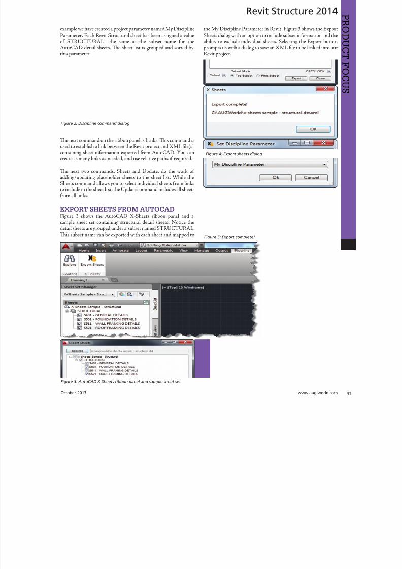
8122019 augi world 2013 10
httpslidepdfcomreaderfullaugi-world-2013-10 4152October 2013 wwwaugiworldcom
Revit Structure 2014
example we have created a project parameter named My DisciplineParameter Each Revit Structural sheet has been assigned a valueof SRUCURALmdashthe same as the subset name for theAutoCAD detail sheets Te sheet list is grouped and sorted bythis parameter
Te next command on the ribbon panel is Links Tis command isused to establish a link between the Revit project and XML file(s)
containing sheet information exported from AutoCAD You cancreate as many links as needed and use relative paths if required
Te next two commands Sheets and Update do the work ofaddingupdating placeholder sheets to the sheet list While theSheets command allows you to select individual sheets from linksto include in the sheet list the Update command includes all sheetsfrom all links
EXPORT SHEETS FROM AUTOCADFigure 3 shows the AutoCAD X-Sheets ribbon panel and asample sheet set containing structural detail sheets Notice thedetail sheets are grouped under a subset named SRUCURALTis subset name can be exported with each sheet and mapped to
the My Discipline Parameter in Revit Figure 3 shows the ExportSheets dialog with an option to include subset information and theability to exclude individual sheets Selecting the Export buttonprompts us with a dialog to save an XML file to be linked into ourRevit project
Figure 2 Discipline command dialog
Figure 3 AutoCAD X-Sheets ribbon panel and sample sheet set
Figure 4 Export sheets dialog
Figure 5 Export complete
8122019 augi world 2013 10
httpslidepdfcomreaderfullaugi-world-2013-10 4252wwwaugicom October 20
Revit Structure 2014
PRO
DUCT
FOCUS
ESTABLISH LINK TO XML FILE IN REVIT
PROJECTFigure 6 shows the Manage Links dialog A link has been added tothe XML file we generated when exporting sheets from AutoCADNotice there is an option to make the link path relative to our
Revit Project location
IMPORT SHEETS FROM XML LINKFigure 7 shows the Revit Structure sheet list before any sheetshave been imported from AutoCAD After selecting the Sheetscommand we are prompted with a Manage Sheets dialog
For this example we have selected all sheets from the XML linto include in our sheet list After confirming the dialog neplaceholder sheets are immediately added to the sheet list angrouped according to the SubsetDiscipline mapping Te neplaceholder sheets are identified behind the scenes as being relatto the X-Sheets XML link for later updating
Figure 6 Manage Links dialog
Figure 9 Sheet list after import
Figure 7 Sheet list before import
Figure 8 Manage Sheets dialog
The X-Sheets
add-in is a great tool
for incorporating
AutoCAD sheets into
a Revit sheet list
8122019 augi world 2013 10
httpslidepdfcomreaderfullaugi-world-2013-10 4352October 2013 wwwaugiworldcom
Revit Structure 2014
UPDATE SHEETSFigure 10 shows the Export Sheets dialog in AutoCAD afterdetail sheets have been renumbered to include ldquo-Ardquo When changesare made to AutoCAD sheets the original export steps must befollowed to replace the XML file linked to our Revit project Oncethe XML has been replaced simply run the Update command inRevit to update the sheet list
SUMMARYTe X-Sheets add-in is a great tool for incorporating AutoCADsheets into a Revit sheet list Te add-in saves time by automatically
adding placeholder sheets eliminates room for error in manualtranslation and helps to keep your sheet list up to date withminimal effort
Jonathan Albert is co-founder of BIM- pulse echnologies LLC amp SeniorApplications Developer at LindemanBentzon Bojack Engineering in Cler-mont Florida He has worked morethan 15 years implementing and usingBIM echnology for some of the na-tionrsquos leading production home build-
ers Most recently he has developedBIMpulse an Options Managementand Material akeoff Add-In for Au-toCAD Architecture Revit and Au-todesk Design Review Jonathan can bereached at jonalbbecom
Figure 10 Export Sheets dialog after sheet renumber
Figure 11 Update complete
Figure 12 Sheet list after update
The X-Sheets
add-in is agreat tool for
incorporatingAutoCAD
sheets intoa Revit
sheet list
8122019 augi world 2013 10
httpslidepdfcomreaderfullaugi-world-2013-10 4452wwwaugicom October 20
AutoCAD Civil 3D 2014
PRO
DUCT
FOCUS
by Tench Tilghma
Itrsquos a fact Jack You invested money in the worldrsquosmost popular civil engineering and designsoftware You (or someone else) will have workhard to make the software run productively
and publish the engineering design or surveywork acceptably
Every AutoCADreg Civil 3Dreg user will tell you ldquoYou need a Civil3D templaterdquo
heyrsquore right sort of You need more than one he suppliedexample Autodesk template files (dwt) are just thatmdashexamplesto show you that things are possible A great many ldquothingsrdquo arepossible in Civil 3D It is data-centric model-based software Asa dedicated content developer and continuous customizer of Civil3D I hope the following perspectives and tips help shorten thecycles and reduce the pain of customizing the software
AutoCAD Civil 3D was constructed from the ground up todisconnect the survey and engineering data from how that missioncritical data is represented
WITH LIBERTY COMES RESPONSIBILITYAs far as Autodesk is concerned what you want the many Civil 3Dldquothingsrdquo to look like and how the Civil 3D data is to be annotated istotally up to you hatrsquos not really true is it Plan sets are publishedin arcane symbolic graphic languages designed to faithfully conveythe design intent to someone who must build it with a plan checkeror two (or three or four) stuck in between
As a professional I prefer to call them ldquoPlan Set Languagesrdquo hhelps focus the development to the publishing of Civil 3D datMost people throw a fuzzy word around this complex mix human perceptive agendas and call that ldquoCAD Standardsrdquo
ldquohe wonderful thing about standards is there are so many of themndash Grace Hopper et al
PICK A STANDARD AND MANAGE BY ITldquoWe already have a CAD standardrdquo his may be the first anworst Civil 3D customization mistake any skilled AutoCAD usor organization can make he odds are the CAD standards yoemployed before do not take into account the data centric anmodel-based methods that Civil 3D employs Simply put Civ3D manages how things look and behave by Style Primitive-basAutoCADreg standards may get in the way
Older ldquoCADrdquo standards by definition must be focused on CAprimitive publishing specifics layer textstyle (height) blo
CustomizeCorrectly
Figure 1 Standards documentation is required
8122019 augi world 2013 10
httpslidepdfcomreaderfullaugi-world-2013-10 4552October 2013 wwwaugiworldcom
AutoCAD Civil 3D 2014
graphics standards and so on In raw AutoCAD and AutoCAD-based drafting and design software the only way to manage all theCAD primitive stuff was to be SPECIFIC about all the details allthe time he drawing we create and check things in is the drawingwe publish
If you publish work out of quality control or design drawingsin Civil 3D this is a sign you may be missing some of its timesaving advantages
While the old CADD process works it requires a lot of man-hoursdedicated to maintaining and checking the details Clearly one ofCivil 3Drsquos critical design development goals is to rid organizationsand Civil 3D users of this expensive man-hour burden and costhe idea here is to put the man-hours into the iterative engineeringprocess instead Civil 3D Feature data and Style make this possible
Civil 3D styles and label styles do employ the AutoCAD layertextstyle block references AutoCAD customizers are used tohe software is still called ldquoAutoCADrdquo Civil 3D after all Our
AutoCAD customization skills still apply But we must applythem differently and much more systematically Herersquos whyhellip
YOU NAME ITmdashTHE MOST CRITICAL
STANDARDCivil 3D Styles and label styles employ (reference) the AutoCADldquonamedrdquo parts to ldquoexpressrdquo themselves Style tools just look for andmatch the ldquorightrdquo names Change the ldquomeaningrdquo andor definitionof the names and you can change anything
We call this fundamental property and benefit of object-orientedprogramming the Power of Names In programming speak this
concept and practical reality is called a ldquonamespacerdquo
Such a namespace in engineering speak answers the questionldquoIn this context does ldquoDIrdquo means a ldquodrop inletrdquo In a minute wersquollget to the structure of a customization ldquonamespacerdquo for Civil 3DAutoCAD references
THE POWER OF NAMESGo ahead and make a drawing from your current Civil 3D templateoss in some Civil 3D data by data reference from any projectUse the RENAME command on any of the old AutoCAD stylecollectionsmdashtry layers
Rename like crazy Your existing Civil 3D styles and label styles willhappily work exactly the same he components in the Civil3DFeature and Label Styles will go to your renamed layers Becauseyou didnrsquot change the properties of the layers either nothingchanges Itrsquos not too exciting until you think about what it means
FOLLOW A SCRIPTObviously as customizers we never want to do this sort of workmanually Computers are faster better and more exact typists thanwe are We commonly rely on AutoCAD scripts generated from
Microsoft Excel spreadsheets (See the end of the article)
here are a couple of key collections in the object model thatCivil 3D walls off from this form of potentially destructiveuser madnessmdashObject Properties in Drawing Settings and afew things like Figure Prefix Dbs values that are not ever in thedrawing per se
WHAT REALLY MATTERSAutoCAD Civil 3D style is mind-boggling abstraction Everythingis designed and built to point at references We can employ styleabstraction for our benefit
In one sense AutoCAD Civil 3D style doesnrsquot care aboutAutoCAD layer standards block libraries textstyles colorsplotstyles or really anything else AutoCAD From our perspectiveall the Civil 3D styles care about are the arbitrary and exact namesthey currently reference
he Civil 3D customizerrsquos dilemma Keep book on the exactnames here are a lot of names to keep track of You must havea plan You must have rules You must employ the same processesconsistently in the same order to get quality assured results
Figure 2 Are description keys a namespace
Figure 3 Rename the AutoCAD reference names
8122019 augi world 2013 10
httpslidepdfcomreaderfullaugi-world-2013-10 4652wwwaugicom October 20
AutoCAD Civil 3D 2014
PRO
DUCT
FOCUS
hat Current word is a wonderfully relative term forthe customizer
Build a set of styles extract them to another drawing rename andor redefine the references and quickly produce a different resulthe Current method makes it easy to propagate success andmistake It makes it repetitively tedious to make fixes
NO CAN STOPAs innovative content developers for Civil 3D we chose to employthe National CAD Standard (NCS) as our fundamental Namestandard Not because we like the NCS but because of all thehard-won experience expressed in these tested standards Inmany respects we employ the NCS UDS (Uniform DrawingStandards) etc in our Production Solution products becauseof the underlying How and Why for those standards and theirpractical published Rules
We want to build faster high-performance vehicles Why reinventthe wheel when we can improve on it
STANDARD KEYS TO NAMEShe NCS employs a hierarchical concept of Keys here areMajor Keys Minor Keys etc that have order precedence and aninterpreted meaning he NCS Layer standard employs the Key-based rules to produce defined meanings to Layers
You can in practice employ the same Layer Keys to be genericor granularly specific about where the published results go Allthe annotation can go to one layer or many different layers forexample Styles andor sets do the work
his KEY CODE structure produces a flexible and structuredldquonamespacerdquo we referred to earlier Itrsquos a namespace that both thesoftware can employ and is relatively easy for us dumb-bunnyhumans to learn to decode when we must Most of the time theusers donrsquot and shouldnrsquot care anyway
Figure 4 shows a few of the NCS ldquolikerdquo Keys we employ in ourproducts We employ them for both layer and block collectionsand even the structure of libraries hey may even be employedin Civil 3D style names when thatrsquos appropriate (See the endof the article)
he customizing key point is that the meanings of these specificKeys can be translated into any other set (or sets) of different
Keys he Key changes can be systematically applied to whatevAutoCAD reference tables and resources we require
he results of any changes will float uphill to the named Civil 3Styles we choose to employ hink of all the AutoCAD referencin a template as a Set
BEYOND AUTOCADNow wersquove looped back to Civil 3D style tools and substantivetheir names and what their parts refer to Welcome to the circuland iterative world that is customizing and employing Civil 3D
Aside from the requisite customization skills and experience build style tools our practical biggest customization issues afrankly Civil 3D human interface issues
No matter how you cut it you have a very limited amount of tespace to help users decide on the ldquorightrdquo style tool to use he teof the style toolrsquos name is all you get to deliver to the user ypicaitrsquos a pick box list
You might get lucky and have the Style Viewer but that Viewcannot represent everything a style can do
FEATURE STYLES NAMESWhat we call the ldquoFeature Stylesrdquo (the Ci3D Featurersquos graphics) require that our stynames explain in simple readable humterms what the tool does For examplesurface style like ldquoContours 1-5 Proposed
Figure 4 Some standard keys
Figure 5 The limitations of user style choice
8122019 augi world 2013 10
httpslidepdfcomreaderfullaugi-world-2013-10 4752October 2013 wwwaugiworldcom
AutoCAD Civil 3D 2014
For the common and most understood features this makes somesense ASCII order rules how named Styles organize Names mustsort that out
Complex graphic features such as Views have a lot more going onldquoMy Standard Profile Viewrdquo doesnrsquot cut it except in a publishingtemplate he style names must be more informative and specificDoes the Profile View include grid lines or not We must recognizethat the engineering data behind what we want to visualize isvariable and the user will have specific needs to get work doneWhen you check a surface you need to see the data in differentways than when the result is published
Choice of style is productive Choice is not contrary to publishingstandards unless you mix the two
LABEL STYLE NAME FACTORSWhen we open the Alignment Label Style collection andorstart to assemble Sets of Label Styles we see any hope of namesimplicity for label styles disappears in a flash
he majority of styles are annotative here are a lot of formsand specific types of them Label Style ype matters he smartcustomizer employs the Label Style Default (LSD) hierarchyexpressed in the oolspacegtgtSettings tab or ignores it and missesthe benefits
Label styles often must have a geometric framework to themItrsquos about ldquoreadabilityrdquo and meaning Whether this label goes upor down or attaches here and not there is critical to annotativeclarity he graphic structure of many data-rich label styles alsofundamentally matters to the stylersquos upgrade stability herersquos
a maintenance cost to pay if you refuse to employ consistentgeometric structures in label styles
CUSTOM USAGECan users see the right data and at the right time Will the useremploy a general alignment parcel or figure line and curve labelHow do they see the difference in a simple list It is easy to misshow ldquoon-the-flyrdquo annotative information negatively or positivelyeffects design time decision making and quality control Peoplewill make things to get the job done Do you fight it or enable ithe Simple Style Rules anyone can learn
THE CIVIL 3D NAMESPACESA Civil 3D style naming convention must be human readablecreate order in the interface and therefore include a rule-basedeasy-to-learn code system that expresses quickly the critical detailso customize we need two namespaces One for the top-end stylesand one for the back-end AutoCAD references In productionprojects we need a third namespace for how we name the featuresbut thatrsquos another story
his client and this project demand these CAD standards specificsAnother client and project demand something different Even ifyou donrsquot believe you regularly face that common problem you
still have to improve the internal production templates themselveshe method and process arenrsquot different
In our project-based production world Civil 3D users andsupervisory staff can always work with the familiar and publishwhat is demanded in a customized publishing template hetwo-pronged project template approach has the added benefit ofpotentially quantifying the costs and real return on investment forthe customization itself
CUSTOMIZE TO PUBLISH ON DEMANDIn practical terms we can change the expressed graphicsmdashthe PlanSet Language (CAD standards) with managed intern level staffEven non-CAD people can see and identify graphic differenceOnly basic AutoCAD and basic spreadsheets skills are requiredfor much of the work if you have a naming plan ldquoChange thatmanhole block to look like this manhole blockrdquo Your ldquothatrdquo mustbe specific
ldquoPublish on demandrdquo capability is a productivity and competitive
advantage but it takes repetitions to develop and practice the skillsWe must endlessly customize Civil 3Dmdashreap the benefits
CIVIL 3D NAME RESOURCEShe Standard Keys the NCS-like AutoCAD reference namespacehe Jump Standards includes the detailed and documented stylenamespace Find them at wwwcadpilotcomresourcesaspx
Excel Cell Formula Script ExampleHerersquos the pseudo code for a typical formula-based layer script thatmakes a layer table with all the details filled in from a cell It createsa series of quote wrapped strings when a column of such cells is
copied and pasted to an ASCII text file
ltLayerCommandgtampCHAR(13)amprdquoSrdquoampCHAR(13)ampltOldLayergtampCHAR(13)amprdquoRrdquoampCHAR(13)ampltNewLayergtampCHAR(13)ampltNewLayergtampCHAR(13)amprdquoCrdquoampCHAR(13)ampltColorgtampCHAR(13)ampCHAR(13)amprdquoLWrdquoampCHAR(13)ampltLineweightgtampCHAR(13)ampCHAR(13)amprdquoPSrdquoampCHAR(13)ampltPlotstylegtampCHAR(13)ampCHAR(13)amprdquoDrdquoampCHAR(13)ampltDescriptiongtampCHAR(13)ampltNewLayergtampCHAR(13)
ench ilghman is President ofMoreCompetency Inc an Autodesk
Developer Partner specializing in in-novative Civil 3D Production Solu-tion products and consulting services
for AutoCAD Civil 3D ench is aregular speaker at Autodesk Univer-sity and AEC industry events on thetopics of technology adoption innova-tion and (his personal favorite) peopleskills He posts on the Get the Jump onCivil 3D blog
8122019 augi world 2013 10
httpslidepdfcomreaderfullaugi-world-2013-10 4852wwwaugicom October 20
Revit MEP 2014
PRO
DUCT
FOCUS
by Todd Shackelfor
W
hen any new technology hits theground there are plenty of false startsand backtracking In time shortcutsare found tricks of the trade are
discovered and best practices are defined So is thecase with Autodeskreg Revitreg even for MEP users his article willoutline a logical roadmap of technical and non-technical mustdorsquos and donrsquot dorsquos for transitioning to Revit MEP From settingexpectations defining goals and plotting in Revit to addressingBIM IPD and VDC the checklist of elements required to helpRevit really work in an office will be covered Every implementationwill come with resistance workflow issues and plenty of headachesbut staying on course and hitting the important milestones alongthe way will help reduce stress of something akin to the craziestfamily trip ever
FIRST CONSIDERATIONS ndash SOFTWAREOne might think it is all about Revit he truth is that Revit reallywants to act as a central location for data that is constantly on themove Much like a smartphone leverages the power of thousandsof applications Revit plugs into workflows with more than a fewAutodesk programs as well as a host of third-party programs hesimple fact that the Building Design Suite comes with so manyvaried applications is a pretty big hint that Revit wants to play ona team Firms need to look at their processes from a high level andlook for the best workflows and programs for the team
FIRST CONSIDERATIONS ndash HARDWAREEvaluate the PCs and know what their capabilities are anknow what Revit requires Search Autodeskrsquos website for systerequirements for Revit products Requirements for three tieof deployment are listed for systems covering an entry-levconfiguration a balanced performance configuration and performance configuration Certified and supported graphi
hardware is also accessible from this page he non-hardwasavvy should seek input from an I professional Revit cannand will not perform on outdated or entry-level PCs and thperson leading the implementation usually takes the blame wheexpectations fall short Best advice is overkill it on hardware Whseems over the top today is inadequate in a year
FIRST CONSIDERATIONS ndash TRAININGhere is no way to get around the fact that training will need tbe done Even if every person in the firm has already used Revtraining on using Revit company standards must still take plachere are many ways to deliver training An in-house expe
TransitionRoadmap
8122019 augi world 2013 10
httpslidepdfcomreaderfullaugi-world-2013-10 4952October 2013 wwwaugiworldcom
Revit MEP 2014
can provide just-in-time all the time Autodesk resellers andconsultants typically provide three- to five-day immersion trainingand short- to long-term consulting here are countless web-based training optionsmdashfree and paid Community colleges thatoffer Revit training usually require a final project that will putstudents through the paces and better entrench the
knowledge and skills
On the down side Revit MEP-specific classes areall but impossible to find Lastly the extreme go-getter can buy a book and learn on the job In realityeveryone learns differently and being preparedto leverage all these types of training is the bestsolution People will gravitate to the solution thatworks best for them when it is provided
FIRST CONSIDERATIONS ndash
LINE UP YOUR DUCTS (UGH hellip
DUCKS)Set appropriate goals based on the size of thefirm Small medium and large firms will havedrastically different goals and timelines It mightseem odd but small firms have the upper hand inadopting new technologies and processes hinkabout it What is easiermdashgetting 3 people toagree or 300 Recognize that an AE firm will havecompletely different goals and processes than a solely MEP firmDuring any shift in process be prepared to support the old andnew at the same time and sometimes in the same project hiswill mean keeping symbols in Revit as close as possible to symbols
in AutoCADreg Consider how quality reviews are done and clientexpectations When things look different it is an impediment tochange Minimizing the impediments will help tremendously
All that being said communication is the real key to most everyprojectrsquos success It is important keep information flowing upand down the chain and set the expectations early Some criticalexpectations for this type of implementation are that things will gowrong things will take longer things will look different things willhave to change and things will continue to evolve Remind usersand management of the progress they have been made by trackingand documenting incremental goals
With a general direction and expectations set itrsquos time to get morespecific about the journey his trip is a long one and a phasedapproach is best Firms can tailor the following phasing to suitindividual needs his example has four phasesmdasheach with itsown goals building off the previous phases
Phase 1 - Goals1 Create construction documents2 Improved collaboration3 Interference mitigationo obtain these goals the following Revit items need to be addressedhe first group addresses the goal of good construction documentshe second group deals with process and keeping things standardhe space available in this article doesnrsquot allow for ldquoHow torsquosrdquo foreach item but each is well documented in the Revit help pageand all over the Internet Get a couple points of view and marrythe possibilities to the culture and needs of the firm in question
bull Line styles createdbull Fonts set for plan text titles title blocks tags and everything
elsebull Object styles ndash Define the weight color tone and transparency
of everything bull Incorporation of standard detailsbull Browser organization ndash Decide how you want to see views
organizedbull Filters ndash Know if you need standard filters and create them
ahead of timebull Phasesbull View templatesbull Project templatebull Duct Stylesbull Pipe stylesbull Family creation
Figure 1
Figure 2
8122019 augi world 2013 10
httpslidepdfcomreaderfullaugi-world-2013-10 5052
8122019 augi world 2013 10
httpslidepdfcomreaderfullaugi-world-2013-10 5152October 2013 wwwaugiworldcom
Inside Track
CSCrsquos Integratorhttpwwwcscworldcom
Integrator is a tool that allows you to synchronize structural designscreated in CSCrsquos Fastrak Building Designer (steel building designsoftware) and Orion (structural concrete building design software)with Autodeskreg Revitreg 2014
ldquoLeading structural software provider CSC has released a new versionof Integrator its market leading Structural BIM integration softwarefor synchronizing code-compliant models produced in CSCrsquos buildingdesign software Fastrak and Orion with Autodeskreg Revitreg Nowfully compatible with Autodesk Revit 2014 structural engineers andtechnicians have even greater control during the integration process
Using Integrator full and part models can be synchronized betweenFastrak or Orion and Autodesk Revit with the ability to manageadded deleted and modified members and their associated
design datardquo
BiMTOOLShttpwwwsofistikcom
BiMOOLS is a set of productivity tools that are designed forAutodeskreg Revitreg 2014 Te plug-in can be installed from theAutodesk Exchange Apps store
ldquoTe first international version of the SOFiSiK BiMOOLS isnow available SOFiSiK BiMOOLS is a collection of free tools forAutodeskreg Revitreg Structure to enhance the productivity up to 50Te features range from easy font type substitution and automaticgeneration of dimensional lines over the automatic positioning ofstructural elements to the comprehensive Family Creator to generatefamilies of eg beams braces and columns for optimal communicationwith FE analysis tools like the SOFiSiK softwarerdquo
Find further information and download links for Revit 2012 and
2013 on the dedicated BiMOOLS website
Autodesk AutoCAD 360 21httpswwwautocad360com
Autodeskreg AutoCADreg 360 is a mobile and web-based application that allows you to view editand share drawing files created with AutoCADand AutoCAD-based products Te mobile appis available from the Apple iunes App Store andGoogle Play Store
ldquoAutoCAD 360 is a free easy-to-use drawing and drafting mobileapp that allows you to view edit and share AutoCAD drawingsmdashanytime anywhere Simplify site visits and fieldwork with powerfuldesign review and markup toolsmdashavailable online and offline
Seamlessly share drawings with others across desktop web andmobile devices Easily access drawings from web browsers using
the free companion AutoCAD 360 web app AutoCAD 360Pro subscription plans further expand the functionality of
the app bringing additional capabilities to the fieldrdquo
Te updates that are in this latest release arebull Stunning high-resolution drawings display
via full retina supportbull Better display through improved PDF
supportbull Easy switching between metric and imperial
unitsbull Saves time with faster app loading bull Improved collaboration through in-app
notifications and streamlined sharing bull New properties for Properties Palette
(Pro version)
AUGIWorldbrings
you recentdevelopmentsin Autodeskand AEC-relatedsoftwareitems
Until next issue
If you have some news to share with us for future issues please let usknow Likewise if you are a user of a featured product or news itemand would like to write a review we want to know
By Lee Ambrosius
8122019 augi world 2013 10
httpslidepdfcomreaderfullaugi-world-2013-10 5252
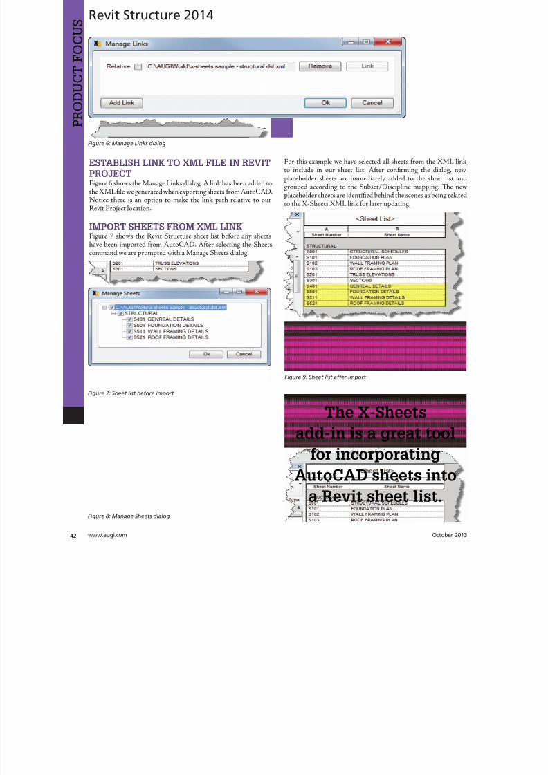
8122019 augi world 2013 10
httpslidepdfcomreaderfullaugi-world-2013-10 4252wwwaugicom October 20
Revit Structure 2014
PRO
DUCT
FOCUS
ESTABLISH LINK TO XML FILE IN REVIT
PROJECTFigure 6 shows the Manage Links dialog A link has been added tothe XML file we generated when exporting sheets from AutoCADNotice there is an option to make the link path relative to our
Revit Project location
IMPORT SHEETS FROM XML LINKFigure 7 shows the Revit Structure sheet list before any sheetshave been imported from AutoCAD After selecting the Sheetscommand we are prompted with a Manage Sheets dialog
For this example we have selected all sheets from the XML linto include in our sheet list After confirming the dialog neplaceholder sheets are immediately added to the sheet list angrouped according to the SubsetDiscipline mapping Te neplaceholder sheets are identified behind the scenes as being relatto the X-Sheets XML link for later updating
Figure 6 Manage Links dialog
Figure 9 Sheet list after import
Figure 7 Sheet list before import
Figure 8 Manage Sheets dialog
The X-Sheets
add-in is a great tool
for incorporating
AutoCAD sheets into
a Revit sheet list
8122019 augi world 2013 10
httpslidepdfcomreaderfullaugi-world-2013-10 4352October 2013 wwwaugiworldcom
Revit Structure 2014
UPDATE SHEETSFigure 10 shows the Export Sheets dialog in AutoCAD afterdetail sheets have been renumbered to include ldquo-Ardquo When changesare made to AutoCAD sheets the original export steps must befollowed to replace the XML file linked to our Revit project Oncethe XML has been replaced simply run the Update command inRevit to update the sheet list
SUMMARYTe X-Sheets add-in is a great tool for incorporating AutoCADsheets into a Revit sheet list Te add-in saves time by automatically
adding placeholder sheets eliminates room for error in manualtranslation and helps to keep your sheet list up to date withminimal effort
Jonathan Albert is co-founder of BIM- pulse echnologies LLC amp SeniorApplications Developer at LindemanBentzon Bojack Engineering in Cler-mont Florida He has worked morethan 15 years implementing and usingBIM echnology for some of the na-tionrsquos leading production home build-
ers Most recently he has developedBIMpulse an Options Managementand Material akeoff Add-In for Au-toCAD Architecture Revit and Au-todesk Design Review Jonathan can bereached at jonalbbecom
Figure 10 Export Sheets dialog after sheet renumber
Figure 11 Update complete
Figure 12 Sheet list after update
The X-Sheets
add-in is agreat tool for
incorporatingAutoCAD
sheets intoa Revit
sheet list
8122019 augi world 2013 10
httpslidepdfcomreaderfullaugi-world-2013-10 4452wwwaugicom October 20
AutoCAD Civil 3D 2014
PRO
DUCT
FOCUS
by Tench Tilghma
Itrsquos a fact Jack You invested money in the worldrsquosmost popular civil engineering and designsoftware You (or someone else) will have workhard to make the software run productively
and publish the engineering design or surveywork acceptably
Every AutoCADreg Civil 3Dreg user will tell you ldquoYou need a Civil3D templaterdquo
heyrsquore right sort of You need more than one he suppliedexample Autodesk template files (dwt) are just thatmdashexamplesto show you that things are possible A great many ldquothingsrdquo arepossible in Civil 3D It is data-centric model-based software Asa dedicated content developer and continuous customizer of Civil3D I hope the following perspectives and tips help shorten thecycles and reduce the pain of customizing the software
AutoCAD Civil 3D was constructed from the ground up todisconnect the survey and engineering data from how that missioncritical data is represented
WITH LIBERTY COMES RESPONSIBILITYAs far as Autodesk is concerned what you want the many Civil 3Dldquothingsrdquo to look like and how the Civil 3D data is to be annotated istotally up to you hatrsquos not really true is it Plan sets are publishedin arcane symbolic graphic languages designed to faithfully conveythe design intent to someone who must build it with a plan checkeror two (or three or four) stuck in between
As a professional I prefer to call them ldquoPlan Set Languagesrdquo hhelps focus the development to the publishing of Civil 3D datMost people throw a fuzzy word around this complex mix human perceptive agendas and call that ldquoCAD Standardsrdquo
ldquohe wonderful thing about standards is there are so many of themndash Grace Hopper et al
PICK A STANDARD AND MANAGE BY ITldquoWe already have a CAD standardrdquo his may be the first anworst Civil 3D customization mistake any skilled AutoCAD usor organization can make he odds are the CAD standards yoemployed before do not take into account the data centric anmodel-based methods that Civil 3D employs Simply put Civ3D manages how things look and behave by Style Primitive-basAutoCADreg standards may get in the way
Older ldquoCADrdquo standards by definition must be focused on CAprimitive publishing specifics layer textstyle (height) blo
CustomizeCorrectly
Figure 1 Standards documentation is required
8122019 augi world 2013 10
httpslidepdfcomreaderfullaugi-world-2013-10 4552October 2013 wwwaugiworldcom
AutoCAD Civil 3D 2014
graphics standards and so on In raw AutoCAD and AutoCAD-based drafting and design software the only way to manage all theCAD primitive stuff was to be SPECIFIC about all the details allthe time he drawing we create and check things in is the drawingwe publish
If you publish work out of quality control or design drawingsin Civil 3D this is a sign you may be missing some of its timesaving advantages
While the old CADD process works it requires a lot of man-hoursdedicated to maintaining and checking the details Clearly one ofCivil 3Drsquos critical design development goals is to rid organizationsand Civil 3D users of this expensive man-hour burden and costhe idea here is to put the man-hours into the iterative engineeringprocess instead Civil 3D Feature data and Style make this possible
Civil 3D styles and label styles do employ the AutoCAD layertextstyle block references AutoCAD customizers are used tohe software is still called ldquoAutoCADrdquo Civil 3D after all Our
AutoCAD customization skills still apply But we must applythem differently and much more systematically Herersquos whyhellip
YOU NAME ITmdashTHE MOST CRITICAL
STANDARDCivil 3D Styles and label styles employ (reference) the AutoCADldquonamedrdquo parts to ldquoexpressrdquo themselves Style tools just look for andmatch the ldquorightrdquo names Change the ldquomeaningrdquo andor definitionof the names and you can change anything
We call this fundamental property and benefit of object-orientedprogramming the Power of Names In programming speak this
concept and practical reality is called a ldquonamespacerdquo
Such a namespace in engineering speak answers the questionldquoIn this context does ldquoDIrdquo means a ldquodrop inletrdquo In a minute wersquollget to the structure of a customization ldquonamespacerdquo for Civil 3DAutoCAD references
THE POWER OF NAMESGo ahead and make a drawing from your current Civil 3D templateoss in some Civil 3D data by data reference from any projectUse the RENAME command on any of the old AutoCAD stylecollectionsmdashtry layers
Rename like crazy Your existing Civil 3D styles and label styles willhappily work exactly the same he components in the Civil3DFeature and Label Styles will go to your renamed layers Becauseyou didnrsquot change the properties of the layers either nothingchanges Itrsquos not too exciting until you think about what it means
FOLLOW A SCRIPTObviously as customizers we never want to do this sort of workmanually Computers are faster better and more exact typists thanwe are We commonly rely on AutoCAD scripts generated from
Microsoft Excel spreadsheets (See the end of the article)
here are a couple of key collections in the object model thatCivil 3D walls off from this form of potentially destructiveuser madnessmdashObject Properties in Drawing Settings and afew things like Figure Prefix Dbs values that are not ever in thedrawing per se
WHAT REALLY MATTERSAutoCAD Civil 3D style is mind-boggling abstraction Everythingis designed and built to point at references We can employ styleabstraction for our benefit
In one sense AutoCAD Civil 3D style doesnrsquot care aboutAutoCAD layer standards block libraries textstyles colorsplotstyles or really anything else AutoCAD From our perspectiveall the Civil 3D styles care about are the arbitrary and exact namesthey currently reference
he Civil 3D customizerrsquos dilemma Keep book on the exactnames here are a lot of names to keep track of You must havea plan You must have rules You must employ the same processesconsistently in the same order to get quality assured results
Figure 2 Are description keys a namespace
Figure 3 Rename the AutoCAD reference names
8122019 augi world 2013 10
httpslidepdfcomreaderfullaugi-world-2013-10 4652wwwaugicom October 20
AutoCAD Civil 3D 2014
PRO
DUCT
FOCUS
hat Current word is a wonderfully relative term forthe customizer
Build a set of styles extract them to another drawing rename andor redefine the references and quickly produce a different resulthe Current method makes it easy to propagate success andmistake It makes it repetitively tedious to make fixes
NO CAN STOPAs innovative content developers for Civil 3D we chose to employthe National CAD Standard (NCS) as our fundamental Namestandard Not because we like the NCS but because of all thehard-won experience expressed in these tested standards Inmany respects we employ the NCS UDS (Uniform DrawingStandards) etc in our Production Solution products becauseof the underlying How and Why for those standards and theirpractical published Rules
We want to build faster high-performance vehicles Why reinventthe wheel when we can improve on it
STANDARD KEYS TO NAMEShe NCS employs a hierarchical concept of Keys here areMajor Keys Minor Keys etc that have order precedence and aninterpreted meaning he NCS Layer standard employs the Key-based rules to produce defined meanings to Layers
You can in practice employ the same Layer Keys to be genericor granularly specific about where the published results go Allthe annotation can go to one layer or many different layers forexample Styles andor sets do the work
his KEY CODE structure produces a flexible and structuredldquonamespacerdquo we referred to earlier Itrsquos a namespace that both thesoftware can employ and is relatively easy for us dumb-bunnyhumans to learn to decode when we must Most of the time theusers donrsquot and shouldnrsquot care anyway
Figure 4 shows a few of the NCS ldquolikerdquo Keys we employ in ourproducts We employ them for both layer and block collectionsand even the structure of libraries hey may even be employedin Civil 3D style names when thatrsquos appropriate (See the endof the article)
he customizing key point is that the meanings of these specificKeys can be translated into any other set (or sets) of different
Keys he Key changes can be systematically applied to whatevAutoCAD reference tables and resources we require
he results of any changes will float uphill to the named Civil 3Styles we choose to employ hink of all the AutoCAD referencin a template as a Set
BEYOND AUTOCADNow wersquove looped back to Civil 3D style tools and substantivetheir names and what their parts refer to Welcome to the circuland iterative world that is customizing and employing Civil 3D
Aside from the requisite customization skills and experience build style tools our practical biggest customization issues afrankly Civil 3D human interface issues
No matter how you cut it you have a very limited amount of tespace to help users decide on the ldquorightrdquo style tool to use he teof the style toolrsquos name is all you get to deliver to the user ypicaitrsquos a pick box list
You might get lucky and have the Style Viewer but that Viewcannot represent everything a style can do
FEATURE STYLES NAMESWhat we call the ldquoFeature Stylesrdquo (the Ci3D Featurersquos graphics) require that our stynames explain in simple readable humterms what the tool does For examplesurface style like ldquoContours 1-5 Proposed
Figure 4 Some standard keys
Figure 5 The limitations of user style choice
8122019 augi world 2013 10
httpslidepdfcomreaderfullaugi-world-2013-10 4752October 2013 wwwaugiworldcom
AutoCAD Civil 3D 2014
For the common and most understood features this makes somesense ASCII order rules how named Styles organize Names mustsort that out
Complex graphic features such as Views have a lot more going onldquoMy Standard Profile Viewrdquo doesnrsquot cut it except in a publishingtemplate he style names must be more informative and specificDoes the Profile View include grid lines or not We must recognizethat the engineering data behind what we want to visualize isvariable and the user will have specific needs to get work doneWhen you check a surface you need to see the data in differentways than when the result is published
Choice of style is productive Choice is not contrary to publishingstandards unless you mix the two
LABEL STYLE NAME FACTORSWhen we open the Alignment Label Style collection andorstart to assemble Sets of Label Styles we see any hope of namesimplicity for label styles disappears in a flash
he majority of styles are annotative here are a lot of formsand specific types of them Label Style ype matters he smartcustomizer employs the Label Style Default (LSD) hierarchyexpressed in the oolspacegtgtSettings tab or ignores it and missesthe benefits
Label styles often must have a geometric framework to themItrsquos about ldquoreadabilityrdquo and meaning Whether this label goes upor down or attaches here and not there is critical to annotativeclarity he graphic structure of many data-rich label styles alsofundamentally matters to the stylersquos upgrade stability herersquos
a maintenance cost to pay if you refuse to employ consistentgeometric structures in label styles
CUSTOM USAGECan users see the right data and at the right time Will the useremploy a general alignment parcel or figure line and curve labelHow do they see the difference in a simple list It is easy to misshow ldquoon-the-flyrdquo annotative information negatively or positivelyeffects design time decision making and quality control Peoplewill make things to get the job done Do you fight it or enable ithe Simple Style Rules anyone can learn
THE CIVIL 3D NAMESPACESA Civil 3D style naming convention must be human readablecreate order in the interface and therefore include a rule-basedeasy-to-learn code system that expresses quickly the critical detailso customize we need two namespaces One for the top-end stylesand one for the back-end AutoCAD references In productionprojects we need a third namespace for how we name the featuresbut thatrsquos another story
his client and this project demand these CAD standards specificsAnother client and project demand something different Even ifyou donrsquot believe you regularly face that common problem you
still have to improve the internal production templates themselveshe method and process arenrsquot different
In our project-based production world Civil 3D users andsupervisory staff can always work with the familiar and publishwhat is demanded in a customized publishing template hetwo-pronged project template approach has the added benefit ofpotentially quantifying the costs and real return on investment forthe customization itself
CUSTOMIZE TO PUBLISH ON DEMANDIn practical terms we can change the expressed graphicsmdashthe PlanSet Language (CAD standards) with managed intern level staffEven non-CAD people can see and identify graphic differenceOnly basic AutoCAD and basic spreadsheets skills are requiredfor much of the work if you have a naming plan ldquoChange thatmanhole block to look like this manhole blockrdquo Your ldquothatrdquo mustbe specific
ldquoPublish on demandrdquo capability is a productivity and competitive
advantage but it takes repetitions to develop and practice the skillsWe must endlessly customize Civil 3Dmdashreap the benefits
CIVIL 3D NAME RESOURCEShe Standard Keys the NCS-like AutoCAD reference namespacehe Jump Standards includes the detailed and documented stylenamespace Find them at wwwcadpilotcomresourcesaspx
Excel Cell Formula Script ExampleHerersquos the pseudo code for a typical formula-based layer script thatmakes a layer table with all the details filled in from a cell It createsa series of quote wrapped strings when a column of such cells is
copied and pasted to an ASCII text file
ltLayerCommandgtampCHAR(13)amprdquoSrdquoampCHAR(13)ampltOldLayergtampCHAR(13)amprdquoRrdquoampCHAR(13)ampltNewLayergtampCHAR(13)ampltNewLayergtampCHAR(13)amprdquoCrdquoampCHAR(13)ampltColorgtampCHAR(13)ampCHAR(13)amprdquoLWrdquoampCHAR(13)ampltLineweightgtampCHAR(13)ampCHAR(13)amprdquoPSrdquoampCHAR(13)ampltPlotstylegtampCHAR(13)ampCHAR(13)amprdquoDrdquoampCHAR(13)ampltDescriptiongtampCHAR(13)ampltNewLayergtampCHAR(13)
ench ilghman is President ofMoreCompetency Inc an Autodesk
Developer Partner specializing in in-novative Civil 3D Production Solu-tion products and consulting services
for AutoCAD Civil 3D ench is aregular speaker at Autodesk Univer-sity and AEC industry events on thetopics of technology adoption innova-tion and (his personal favorite) peopleskills He posts on the Get the Jump onCivil 3D blog
8122019 augi world 2013 10
httpslidepdfcomreaderfullaugi-world-2013-10 4852wwwaugicom October 20
Revit MEP 2014
PRO
DUCT
FOCUS
by Todd Shackelfor
W
hen any new technology hits theground there are plenty of false startsand backtracking In time shortcutsare found tricks of the trade are
discovered and best practices are defined So is thecase with Autodeskreg Revitreg even for MEP users his article willoutline a logical roadmap of technical and non-technical mustdorsquos and donrsquot dorsquos for transitioning to Revit MEP From settingexpectations defining goals and plotting in Revit to addressingBIM IPD and VDC the checklist of elements required to helpRevit really work in an office will be covered Every implementationwill come with resistance workflow issues and plenty of headachesbut staying on course and hitting the important milestones alongthe way will help reduce stress of something akin to the craziestfamily trip ever
FIRST CONSIDERATIONS ndash SOFTWAREOne might think it is all about Revit he truth is that Revit reallywants to act as a central location for data that is constantly on themove Much like a smartphone leverages the power of thousandsof applications Revit plugs into workflows with more than a fewAutodesk programs as well as a host of third-party programs hesimple fact that the Building Design Suite comes with so manyvaried applications is a pretty big hint that Revit wants to play ona team Firms need to look at their processes from a high level andlook for the best workflows and programs for the team
FIRST CONSIDERATIONS ndash HARDWAREEvaluate the PCs and know what their capabilities are anknow what Revit requires Search Autodeskrsquos website for systerequirements for Revit products Requirements for three tieof deployment are listed for systems covering an entry-levconfiguration a balanced performance configuration and performance configuration Certified and supported graphi
hardware is also accessible from this page he non-hardwasavvy should seek input from an I professional Revit cannand will not perform on outdated or entry-level PCs and thperson leading the implementation usually takes the blame wheexpectations fall short Best advice is overkill it on hardware Whseems over the top today is inadequate in a year
FIRST CONSIDERATIONS ndash TRAININGhere is no way to get around the fact that training will need tbe done Even if every person in the firm has already used Revtraining on using Revit company standards must still take plachere are many ways to deliver training An in-house expe
TransitionRoadmap
8122019 augi world 2013 10
httpslidepdfcomreaderfullaugi-world-2013-10 4952October 2013 wwwaugiworldcom
Revit MEP 2014
can provide just-in-time all the time Autodesk resellers andconsultants typically provide three- to five-day immersion trainingand short- to long-term consulting here are countless web-based training optionsmdashfree and paid Community colleges thatoffer Revit training usually require a final project that will putstudents through the paces and better entrench the
knowledge and skills
On the down side Revit MEP-specific classes areall but impossible to find Lastly the extreme go-getter can buy a book and learn on the job In realityeveryone learns differently and being preparedto leverage all these types of training is the bestsolution People will gravitate to the solution thatworks best for them when it is provided
FIRST CONSIDERATIONS ndash
LINE UP YOUR DUCTS (UGH hellip
DUCKS)Set appropriate goals based on the size of thefirm Small medium and large firms will havedrastically different goals and timelines It mightseem odd but small firms have the upper hand inadopting new technologies and processes hinkabout it What is easiermdashgetting 3 people toagree or 300 Recognize that an AE firm will havecompletely different goals and processes than a solely MEP firmDuring any shift in process be prepared to support the old andnew at the same time and sometimes in the same project hiswill mean keeping symbols in Revit as close as possible to symbols
in AutoCADreg Consider how quality reviews are done and clientexpectations When things look different it is an impediment tochange Minimizing the impediments will help tremendously
All that being said communication is the real key to most everyprojectrsquos success It is important keep information flowing upand down the chain and set the expectations early Some criticalexpectations for this type of implementation are that things will gowrong things will take longer things will look different things willhave to change and things will continue to evolve Remind usersand management of the progress they have been made by trackingand documenting incremental goals
With a general direction and expectations set itrsquos time to get morespecific about the journey his trip is a long one and a phasedapproach is best Firms can tailor the following phasing to suitindividual needs his example has four phasesmdasheach with itsown goals building off the previous phases
Phase 1 - Goals1 Create construction documents2 Improved collaboration3 Interference mitigationo obtain these goals the following Revit items need to be addressedhe first group addresses the goal of good construction documentshe second group deals with process and keeping things standardhe space available in this article doesnrsquot allow for ldquoHow torsquosrdquo foreach item but each is well documented in the Revit help pageand all over the Internet Get a couple points of view and marrythe possibilities to the culture and needs of the firm in question
bull Line styles createdbull Fonts set for plan text titles title blocks tags and everything
elsebull Object styles ndash Define the weight color tone and transparency
of everything bull Incorporation of standard detailsbull Browser organization ndash Decide how you want to see views
organizedbull Filters ndash Know if you need standard filters and create them
ahead of timebull Phasesbull View templatesbull Project templatebull Duct Stylesbull Pipe stylesbull Family creation
Figure 1
Figure 2
8122019 augi world 2013 10
httpslidepdfcomreaderfullaugi-world-2013-10 5052
8122019 augi world 2013 10
httpslidepdfcomreaderfullaugi-world-2013-10 5152October 2013 wwwaugiworldcom
Inside Track
CSCrsquos Integratorhttpwwwcscworldcom
Integrator is a tool that allows you to synchronize structural designscreated in CSCrsquos Fastrak Building Designer (steel building designsoftware) and Orion (structural concrete building design software)with Autodeskreg Revitreg 2014
ldquoLeading structural software provider CSC has released a new versionof Integrator its market leading Structural BIM integration softwarefor synchronizing code-compliant models produced in CSCrsquos buildingdesign software Fastrak and Orion with Autodeskreg Revitreg Nowfully compatible with Autodesk Revit 2014 structural engineers andtechnicians have even greater control during the integration process
Using Integrator full and part models can be synchronized betweenFastrak or Orion and Autodesk Revit with the ability to manageadded deleted and modified members and their associated
design datardquo
BiMTOOLShttpwwwsofistikcom
BiMOOLS is a set of productivity tools that are designed forAutodeskreg Revitreg 2014 Te plug-in can be installed from theAutodesk Exchange Apps store
ldquoTe first international version of the SOFiSiK BiMOOLS isnow available SOFiSiK BiMOOLS is a collection of free tools forAutodeskreg Revitreg Structure to enhance the productivity up to 50Te features range from easy font type substitution and automaticgeneration of dimensional lines over the automatic positioning ofstructural elements to the comprehensive Family Creator to generatefamilies of eg beams braces and columns for optimal communicationwith FE analysis tools like the SOFiSiK softwarerdquo
Find further information and download links for Revit 2012 and
2013 on the dedicated BiMOOLS website
Autodesk AutoCAD 360 21httpswwwautocad360com
Autodeskreg AutoCADreg 360 is a mobile and web-based application that allows you to view editand share drawing files created with AutoCADand AutoCAD-based products Te mobile appis available from the Apple iunes App Store andGoogle Play Store
ldquoAutoCAD 360 is a free easy-to-use drawing and drafting mobileapp that allows you to view edit and share AutoCAD drawingsmdashanytime anywhere Simplify site visits and fieldwork with powerfuldesign review and markup toolsmdashavailable online and offline
Seamlessly share drawings with others across desktop web andmobile devices Easily access drawings from web browsers using
the free companion AutoCAD 360 web app AutoCAD 360Pro subscription plans further expand the functionality of
the app bringing additional capabilities to the fieldrdquo
Te updates that are in this latest release arebull Stunning high-resolution drawings display
via full retina supportbull Better display through improved PDF
supportbull Easy switching between metric and imperial
unitsbull Saves time with faster app loading bull Improved collaboration through in-app
notifications and streamlined sharing bull New properties for Properties Palette
(Pro version)
AUGIWorldbrings
you recentdevelopmentsin Autodeskand AEC-relatedsoftwareitems
Until next issue
If you have some news to share with us for future issues please let usknow Likewise if you are a user of a featured product or news itemand would like to write a review we want to know
By Lee Ambrosius
8122019 augi world 2013 10
httpslidepdfcomreaderfullaugi-world-2013-10 5252
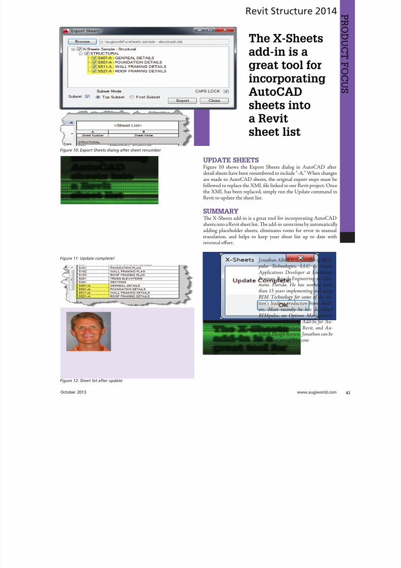
8122019 augi world 2013 10
httpslidepdfcomreaderfullaugi-world-2013-10 4452wwwaugicom October 20
AutoCAD Civil 3D 2014
PRO
DUCT
FOCUS
by Tench Tilghma
Itrsquos a fact Jack You invested money in the worldrsquosmost popular civil engineering and designsoftware You (or someone else) will have workhard to make the software run productively
and publish the engineering design or surveywork acceptably
Every AutoCADreg Civil 3Dreg user will tell you ldquoYou need a Civil3D templaterdquo
heyrsquore right sort of You need more than one he suppliedexample Autodesk template files (dwt) are just thatmdashexamplesto show you that things are possible A great many ldquothingsrdquo arepossible in Civil 3D It is data-centric model-based software Asa dedicated content developer and continuous customizer of Civil3D I hope the following perspectives and tips help shorten thecycles and reduce the pain of customizing the software
AutoCAD Civil 3D was constructed from the ground up todisconnect the survey and engineering data from how that missioncritical data is represented
WITH LIBERTY COMES RESPONSIBILITYAs far as Autodesk is concerned what you want the many Civil 3Dldquothingsrdquo to look like and how the Civil 3D data is to be annotated istotally up to you hatrsquos not really true is it Plan sets are publishedin arcane symbolic graphic languages designed to faithfully conveythe design intent to someone who must build it with a plan checkeror two (or three or four) stuck in between
As a professional I prefer to call them ldquoPlan Set Languagesrdquo hhelps focus the development to the publishing of Civil 3D datMost people throw a fuzzy word around this complex mix human perceptive agendas and call that ldquoCAD Standardsrdquo
ldquohe wonderful thing about standards is there are so many of themndash Grace Hopper et al
PICK A STANDARD AND MANAGE BY ITldquoWe already have a CAD standardrdquo his may be the first anworst Civil 3D customization mistake any skilled AutoCAD usor organization can make he odds are the CAD standards yoemployed before do not take into account the data centric anmodel-based methods that Civil 3D employs Simply put Civ3D manages how things look and behave by Style Primitive-basAutoCADreg standards may get in the way
Older ldquoCADrdquo standards by definition must be focused on CAprimitive publishing specifics layer textstyle (height) blo
CustomizeCorrectly
Figure 1 Standards documentation is required
8122019 augi world 2013 10
httpslidepdfcomreaderfullaugi-world-2013-10 4552October 2013 wwwaugiworldcom
AutoCAD Civil 3D 2014
graphics standards and so on In raw AutoCAD and AutoCAD-based drafting and design software the only way to manage all theCAD primitive stuff was to be SPECIFIC about all the details allthe time he drawing we create and check things in is the drawingwe publish
If you publish work out of quality control or design drawingsin Civil 3D this is a sign you may be missing some of its timesaving advantages
While the old CADD process works it requires a lot of man-hoursdedicated to maintaining and checking the details Clearly one ofCivil 3Drsquos critical design development goals is to rid organizationsand Civil 3D users of this expensive man-hour burden and costhe idea here is to put the man-hours into the iterative engineeringprocess instead Civil 3D Feature data and Style make this possible
Civil 3D styles and label styles do employ the AutoCAD layertextstyle block references AutoCAD customizers are used tohe software is still called ldquoAutoCADrdquo Civil 3D after all Our
AutoCAD customization skills still apply But we must applythem differently and much more systematically Herersquos whyhellip
YOU NAME ITmdashTHE MOST CRITICAL
STANDARDCivil 3D Styles and label styles employ (reference) the AutoCADldquonamedrdquo parts to ldquoexpressrdquo themselves Style tools just look for andmatch the ldquorightrdquo names Change the ldquomeaningrdquo andor definitionof the names and you can change anything
We call this fundamental property and benefit of object-orientedprogramming the Power of Names In programming speak this
concept and practical reality is called a ldquonamespacerdquo
Such a namespace in engineering speak answers the questionldquoIn this context does ldquoDIrdquo means a ldquodrop inletrdquo In a minute wersquollget to the structure of a customization ldquonamespacerdquo for Civil 3DAutoCAD references
THE POWER OF NAMESGo ahead and make a drawing from your current Civil 3D templateoss in some Civil 3D data by data reference from any projectUse the RENAME command on any of the old AutoCAD stylecollectionsmdashtry layers
Rename like crazy Your existing Civil 3D styles and label styles willhappily work exactly the same he components in the Civil3DFeature and Label Styles will go to your renamed layers Becauseyou didnrsquot change the properties of the layers either nothingchanges Itrsquos not too exciting until you think about what it means
FOLLOW A SCRIPTObviously as customizers we never want to do this sort of workmanually Computers are faster better and more exact typists thanwe are We commonly rely on AutoCAD scripts generated from
Microsoft Excel spreadsheets (See the end of the article)
here are a couple of key collections in the object model thatCivil 3D walls off from this form of potentially destructiveuser madnessmdashObject Properties in Drawing Settings and afew things like Figure Prefix Dbs values that are not ever in thedrawing per se
WHAT REALLY MATTERSAutoCAD Civil 3D style is mind-boggling abstraction Everythingis designed and built to point at references We can employ styleabstraction for our benefit
In one sense AutoCAD Civil 3D style doesnrsquot care aboutAutoCAD layer standards block libraries textstyles colorsplotstyles or really anything else AutoCAD From our perspectiveall the Civil 3D styles care about are the arbitrary and exact namesthey currently reference
he Civil 3D customizerrsquos dilemma Keep book on the exactnames here are a lot of names to keep track of You must havea plan You must have rules You must employ the same processesconsistently in the same order to get quality assured results
Figure 2 Are description keys a namespace
Figure 3 Rename the AutoCAD reference names
8122019 augi world 2013 10
httpslidepdfcomreaderfullaugi-world-2013-10 4652wwwaugicom October 20
AutoCAD Civil 3D 2014
PRO
DUCT
FOCUS
hat Current word is a wonderfully relative term forthe customizer
Build a set of styles extract them to another drawing rename andor redefine the references and quickly produce a different resulthe Current method makes it easy to propagate success andmistake It makes it repetitively tedious to make fixes
NO CAN STOPAs innovative content developers for Civil 3D we chose to employthe National CAD Standard (NCS) as our fundamental Namestandard Not because we like the NCS but because of all thehard-won experience expressed in these tested standards Inmany respects we employ the NCS UDS (Uniform DrawingStandards) etc in our Production Solution products becauseof the underlying How and Why for those standards and theirpractical published Rules
We want to build faster high-performance vehicles Why reinventthe wheel when we can improve on it
STANDARD KEYS TO NAMEShe NCS employs a hierarchical concept of Keys here areMajor Keys Minor Keys etc that have order precedence and aninterpreted meaning he NCS Layer standard employs the Key-based rules to produce defined meanings to Layers
You can in practice employ the same Layer Keys to be genericor granularly specific about where the published results go Allthe annotation can go to one layer or many different layers forexample Styles andor sets do the work
his KEY CODE structure produces a flexible and structuredldquonamespacerdquo we referred to earlier Itrsquos a namespace that both thesoftware can employ and is relatively easy for us dumb-bunnyhumans to learn to decode when we must Most of the time theusers donrsquot and shouldnrsquot care anyway
Figure 4 shows a few of the NCS ldquolikerdquo Keys we employ in ourproducts We employ them for both layer and block collectionsand even the structure of libraries hey may even be employedin Civil 3D style names when thatrsquos appropriate (See the endof the article)
he customizing key point is that the meanings of these specificKeys can be translated into any other set (or sets) of different
Keys he Key changes can be systematically applied to whatevAutoCAD reference tables and resources we require
he results of any changes will float uphill to the named Civil 3Styles we choose to employ hink of all the AutoCAD referencin a template as a Set
BEYOND AUTOCADNow wersquove looped back to Civil 3D style tools and substantivetheir names and what their parts refer to Welcome to the circuland iterative world that is customizing and employing Civil 3D
Aside from the requisite customization skills and experience build style tools our practical biggest customization issues afrankly Civil 3D human interface issues
No matter how you cut it you have a very limited amount of tespace to help users decide on the ldquorightrdquo style tool to use he teof the style toolrsquos name is all you get to deliver to the user ypicaitrsquos a pick box list
You might get lucky and have the Style Viewer but that Viewcannot represent everything a style can do
FEATURE STYLES NAMESWhat we call the ldquoFeature Stylesrdquo (the Ci3D Featurersquos graphics) require that our stynames explain in simple readable humterms what the tool does For examplesurface style like ldquoContours 1-5 Proposed
Figure 4 Some standard keys
Figure 5 The limitations of user style choice
8122019 augi world 2013 10
httpslidepdfcomreaderfullaugi-world-2013-10 4752October 2013 wwwaugiworldcom
AutoCAD Civil 3D 2014
For the common and most understood features this makes somesense ASCII order rules how named Styles organize Names mustsort that out
Complex graphic features such as Views have a lot more going onldquoMy Standard Profile Viewrdquo doesnrsquot cut it except in a publishingtemplate he style names must be more informative and specificDoes the Profile View include grid lines or not We must recognizethat the engineering data behind what we want to visualize isvariable and the user will have specific needs to get work doneWhen you check a surface you need to see the data in differentways than when the result is published
Choice of style is productive Choice is not contrary to publishingstandards unless you mix the two
LABEL STYLE NAME FACTORSWhen we open the Alignment Label Style collection andorstart to assemble Sets of Label Styles we see any hope of namesimplicity for label styles disappears in a flash
he majority of styles are annotative here are a lot of formsand specific types of them Label Style ype matters he smartcustomizer employs the Label Style Default (LSD) hierarchyexpressed in the oolspacegtgtSettings tab or ignores it and missesthe benefits
Label styles often must have a geometric framework to themItrsquos about ldquoreadabilityrdquo and meaning Whether this label goes upor down or attaches here and not there is critical to annotativeclarity he graphic structure of many data-rich label styles alsofundamentally matters to the stylersquos upgrade stability herersquos
a maintenance cost to pay if you refuse to employ consistentgeometric structures in label styles
CUSTOM USAGECan users see the right data and at the right time Will the useremploy a general alignment parcel or figure line and curve labelHow do they see the difference in a simple list It is easy to misshow ldquoon-the-flyrdquo annotative information negatively or positivelyeffects design time decision making and quality control Peoplewill make things to get the job done Do you fight it or enable ithe Simple Style Rules anyone can learn
THE CIVIL 3D NAMESPACESA Civil 3D style naming convention must be human readablecreate order in the interface and therefore include a rule-basedeasy-to-learn code system that expresses quickly the critical detailso customize we need two namespaces One for the top-end stylesand one for the back-end AutoCAD references In productionprojects we need a third namespace for how we name the featuresbut thatrsquos another story
his client and this project demand these CAD standards specificsAnother client and project demand something different Even ifyou donrsquot believe you regularly face that common problem you
still have to improve the internal production templates themselveshe method and process arenrsquot different
In our project-based production world Civil 3D users andsupervisory staff can always work with the familiar and publishwhat is demanded in a customized publishing template hetwo-pronged project template approach has the added benefit ofpotentially quantifying the costs and real return on investment forthe customization itself
CUSTOMIZE TO PUBLISH ON DEMANDIn practical terms we can change the expressed graphicsmdashthe PlanSet Language (CAD standards) with managed intern level staffEven non-CAD people can see and identify graphic differenceOnly basic AutoCAD and basic spreadsheets skills are requiredfor much of the work if you have a naming plan ldquoChange thatmanhole block to look like this manhole blockrdquo Your ldquothatrdquo mustbe specific
ldquoPublish on demandrdquo capability is a productivity and competitive
advantage but it takes repetitions to develop and practice the skillsWe must endlessly customize Civil 3Dmdashreap the benefits
CIVIL 3D NAME RESOURCEShe Standard Keys the NCS-like AutoCAD reference namespacehe Jump Standards includes the detailed and documented stylenamespace Find them at wwwcadpilotcomresourcesaspx
Excel Cell Formula Script ExampleHerersquos the pseudo code for a typical formula-based layer script thatmakes a layer table with all the details filled in from a cell It createsa series of quote wrapped strings when a column of such cells is
copied and pasted to an ASCII text file
ltLayerCommandgtampCHAR(13)amprdquoSrdquoampCHAR(13)ampltOldLayergtampCHAR(13)amprdquoRrdquoampCHAR(13)ampltNewLayergtampCHAR(13)ampltNewLayergtampCHAR(13)amprdquoCrdquoampCHAR(13)ampltColorgtampCHAR(13)ampCHAR(13)amprdquoLWrdquoampCHAR(13)ampltLineweightgtampCHAR(13)ampCHAR(13)amprdquoPSrdquoampCHAR(13)ampltPlotstylegtampCHAR(13)ampCHAR(13)amprdquoDrdquoampCHAR(13)ampltDescriptiongtampCHAR(13)ampltNewLayergtampCHAR(13)
ench ilghman is President ofMoreCompetency Inc an Autodesk
Developer Partner specializing in in-novative Civil 3D Production Solu-tion products and consulting services
for AutoCAD Civil 3D ench is aregular speaker at Autodesk Univer-sity and AEC industry events on thetopics of technology adoption innova-tion and (his personal favorite) peopleskills He posts on the Get the Jump onCivil 3D blog
8122019 augi world 2013 10
httpslidepdfcomreaderfullaugi-world-2013-10 4852wwwaugicom October 20
Revit MEP 2014
PRO
DUCT
FOCUS
by Todd Shackelfor
W
hen any new technology hits theground there are plenty of false startsand backtracking In time shortcutsare found tricks of the trade are
discovered and best practices are defined So is thecase with Autodeskreg Revitreg even for MEP users his article willoutline a logical roadmap of technical and non-technical mustdorsquos and donrsquot dorsquos for transitioning to Revit MEP From settingexpectations defining goals and plotting in Revit to addressingBIM IPD and VDC the checklist of elements required to helpRevit really work in an office will be covered Every implementationwill come with resistance workflow issues and plenty of headachesbut staying on course and hitting the important milestones alongthe way will help reduce stress of something akin to the craziestfamily trip ever
FIRST CONSIDERATIONS ndash SOFTWAREOne might think it is all about Revit he truth is that Revit reallywants to act as a central location for data that is constantly on themove Much like a smartphone leverages the power of thousandsof applications Revit plugs into workflows with more than a fewAutodesk programs as well as a host of third-party programs hesimple fact that the Building Design Suite comes with so manyvaried applications is a pretty big hint that Revit wants to play ona team Firms need to look at their processes from a high level andlook for the best workflows and programs for the team
FIRST CONSIDERATIONS ndash HARDWAREEvaluate the PCs and know what their capabilities are anknow what Revit requires Search Autodeskrsquos website for systerequirements for Revit products Requirements for three tieof deployment are listed for systems covering an entry-levconfiguration a balanced performance configuration and performance configuration Certified and supported graphi
hardware is also accessible from this page he non-hardwasavvy should seek input from an I professional Revit cannand will not perform on outdated or entry-level PCs and thperson leading the implementation usually takes the blame wheexpectations fall short Best advice is overkill it on hardware Whseems over the top today is inadequate in a year
FIRST CONSIDERATIONS ndash TRAININGhere is no way to get around the fact that training will need tbe done Even if every person in the firm has already used Revtraining on using Revit company standards must still take plachere are many ways to deliver training An in-house expe
TransitionRoadmap
8122019 augi world 2013 10
httpslidepdfcomreaderfullaugi-world-2013-10 4952October 2013 wwwaugiworldcom
Revit MEP 2014
can provide just-in-time all the time Autodesk resellers andconsultants typically provide three- to five-day immersion trainingand short- to long-term consulting here are countless web-based training optionsmdashfree and paid Community colleges thatoffer Revit training usually require a final project that will putstudents through the paces and better entrench the
knowledge and skills
On the down side Revit MEP-specific classes areall but impossible to find Lastly the extreme go-getter can buy a book and learn on the job In realityeveryone learns differently and being preparedto leverage all these types of training is the bestsolution People will gravitate to the solution thatworks best for them when it is provided
FIRST CONSIDERATIONS ndash
LINE UP YOUR DUCTS (UGH hellip
DUCKS)Set appropriate goals based on the size of thefirm Small medium and large firms will havedrastically different goals and timelines It mightseem odd but small firms have the upper hand inadopting new technologies and processes hinkabout it What is easiermdashgetting 3 people toagree or 300 Recognize that an AE firm will havecompletely different goals and processes than a solely MEP firmDuring any shift in process be prepared to support the old andnew at the same time and sometimes in the same project hiswill mean keeping symbols in Revit as close as possible to symbols
in AutoCADreg Consider how quality reviews are done and clientexpectations When things look different it is an impediment tochange Minimizing the impediments will help tremendously
All that being said communication is the real key to most everyprojectrsquos success It is important keep information flowing upand down the chain and set the expectations early Some criticalexpectations for this type of implementation are that things will gowrong things will take longer things will look different things willhave to change and things will continue to evolve Remind usersand management of the progress they have been made by trackingand documenting incremental goals
With a general direction and expectations set itrsquos time to get morespecific about the journey his trip is a long one and a phasedapproach is best Firms can tailor the following phasing to suitindividual needs his example has four phasesmdasheach with itsown goals building off the previous phases
Phase 1 - Goals1 Create construction documents2 Improved collaboration3 Interference mitigationo obtain these goals the following Revit items need to be addressedhe first group addresses the goal of good construction documentshe second group deals with process and keeping things standardhe space available in this article doesnrsquot allow for ldquoHow torsquosrdquo foreach item but each is well documented in the Revit help pageand all over the Internet Get a couple points of view and marrythe possibilities to the culture and needs of the firm in question
bull Line styles createdbull Fonts set for plan text titles title blocks tags and everything
elsebull Object styles ndash Define the weight color tone and transparency
of everything bull Incorporation of standard detailsbull Browser organization ndash Decide how you want to see views
organizedbull Filters ndash Know if you need standard filters and create them
ahead of timebull Phasesbull View templatesbull Project templatebull Duct Stylesbull Pipe stylesbull Family creation
Figure 1
Figure 2
8122019 augi world 2013 10
httpslidepdfcomreaderfullaugi-world-2013-10 5052
8122019 augi world 2013 10
httpslidepdfcomreaderfullaugi-world-2013-10 5152October 2013 wwwaugiworldcom
Inside Track
CSCrsquos Integratorhttpwwwcscworldcom
Integrator is a tool that allows you to synchronize structural designscreated in CSCrsquos Fastrak Building Designer (steel building designsoftware) and Orion (structural concrete building design software)with Autodeskreg Revitreg 2014
ldquoLeading structural software provider CSC has released a new versionof Integrator its market leading Structural BIM integration softwarefor synchronizing code-compliant models produced in CSCrsquos buildingdesign software Fastrak and Orion with Autodeskreg Revitreg Nowfully compatible with Autodesk Revit 2014 structural engineers andtechnicians have even greater control during the integration process
Using Integrator full and part models can be synchronized betweenFastrak or Orion and Autodesk Revit with the ability to manageadded deleted and modified members and their associated
design datardquo
BiMTOOLShttpwwwsofistikcom
BiMOOLS is a set of productivity tools that are designed forAutodeskreg Revitreg 2014 Te plug-in can be installed from theAutodesk Exchange Apps store
ldquoTe first international version of the SOFiSiK BiMOOLS isnow available SOFiSiK BiMOOLS is a collection of free tools forAutodeskreg Revitreg Structure to enhance the productivity up to 50Te features range from easy font type substitution and automaticgeneration of dimensional lines over the automatic positioning ofstructural elements to the comprehensive Family Creator to generatefamilies of eg beams braces and columns for optimal communicationwith FE analysis tools like the SOFiSiK softwarerdquo
Find further information and download links for Revit 2012 and
2013 on the dedicated BiMOOLS website
Autodesk AutoCAD 360 21httpswwwautocad360com
Autodeskreg AutoCADreg 360 is a mobile and web-based application that allows you to view editand share drawing files created with AutoCADand AutoCAD-based products Te mobile appis available from the Apple iunes App Store andGoogle Play Store
ldquoAutoCAD 360 is a free easy-to-use drawing and drafting mobileapp that allows you to view edit and share AutoCAD drawingsmdashanytime anywhere Simplify site visits and fieldwork with powerfuldesign review and markup toolsmdashavailable online and offline
Seamlessly share drawings with others across desktop web andmobile devices Easily access drawings from web browsers using
the free companion AutoCAD 360 web app AutoCAD 360Pro subscription plans further expand the functionality of
the app bringing additional capabilities to the fieldrdquo
Te updates that are in this latest release arebull Stunning high-resolution drawings display
via full retina supportbull Better display through improved PDF
supportbull Easy switching between metric and imperial
unitsbull Saves time with faster app loading bull Improved collaboration through in-app
notifications and streamlined sharing bull New properties for Properties Palette
(Pro version)
AUGIWorldbrings
you recentdevelopmentsin Autodeskand AEC-relatedsoftwareitems
Until next issue
If you have some news to share with us for future issues please let usknow Likewise if you are a user of a featured product or news itemand would like to write a review we want to know
By Lee Ambrosius
8122019 augi world 2013 10
httpslidepdfcomreaderfullaugi-world-2013-10 5252
8122019 augi world 2013 10
httpslidepdfcomreaderfullaugi-world-2013-10 4552October 2013 wwwaugiworldcom
AutoCAD Civil 3D 2014
graphics standards and so on In raw AutoCAD and AutoCAD-based drafting and design software the only way to manage all theCAD primitive stuff was to be SPECIFIC about all the details allthe time he drawing we create and check things in is the drawingwe publish
If you publish work out of quality control or design drawingsin Civil 3D this is a sign you may be missing some of its timesaving advantages
While the old CADD process works it requires a lot of man-hoursdedicated to maintaining and checking the details Clearly one ofCivil 3Drsquos critical design development goals is to rid organizationsand Civil 3D users of this expensive man-hour burden and costhe idea here is to put the man-hours into the iterative engineeringprocess instead Civil 3D Feature data and Style make this possible
Civil 3D styles and label styles do employ the AutoCAD layertextstyle block references AutoCAD customizers are used tohe software is still called ldquoAutoCADrdquo Civil 3D after all Our
AutoCAD customization skills still apply But we must applythem differently and much more systematically Herersquos whyhellip
YOU NAME ITmdashTHE MOST CRITICAL
STANDARDCivil 3D Styles and label styles employ (reference) the AutoCADldquonamedrdquo parts to ldquoexpressrdquo themselves Style tools just look for andmatch the ldquorightrdquo names Change the ldquomeaningrdquo andor definitionof the names and you can change anything
We call this fundamental property and benefit of object-orientedprogramming the Power of Names In programming speak this
concept and practical reality is called a ldquonamespacerdquo
Such a namespace in engineering speak answers the questionldquoIn this context does ldquoDIrdquo means a ldquodrop inletrdquo In a minute wersquollget to the structure of a customization ldquonamespacerdquo for Civil 3DAutoCAD references
THE POWER OF NAMESGo ahead and make a drawing from your current Civil 3D templateoss in some Civil 3D data by data reference from any projectUse the RENAME command on any of the old AutoCAD stylecollectionsmdashtry layers
Rename like crazy Your existing Civil 3D styles and label styles willhappily work exactly the same he components in the Civil3DFeature and Label Styles will go to your renamed layers Becauseyou didnrsquot change the properties of the layers either nothingchanges Itrsquos not too exciting until you think about what it means
FOLLOW A SCRIPTObviously as customizers we never want to do this sort of workmanually Computers are faster better and more exact typists thanwe are We commonly rely on AutoCAD scripts generated from
Microsoft Excel spreadsheets (See the end of the article)
here are a couple of key collections in the object model thatCivil 3D walls off from this form of potentially destructiveuser madnessmdashObject Properties in Drawing Settings and afew things like Figure Prefix Dbs values that are not ever in thedrawing per se
WHAT REALLY MATTERSAutoCAD Civil 3D style is mind-boggling abstraction Everythingis designed and built to point at references We can employ styleabstraction for our benefit
In one sense AutoCAD Civil 3D style doesnrsquot care aboutAutoCAD layer standards block libraries textstyles colorsplotstyles or really anything else AutoCAD From our perspectiveall the Civil 3D styles care about are the arbitrary and exact namesthey currently reference
he Civil 3D customizerrsquos dilemma Keep book on the exactnames here are a lot of names to keep track of You must havea plan You must have rules You must employ the same processesconsistently in the same order to get quality assured results
Figure 2 Are description keys a namespace
Figure 3 Rename the AutoCAD reference names
8122019 augi world 2013 10
httpslidepdfcomreaderfullaugi-world-2013-10 4652wwwaugicom October 20
AutoCAD Civil 3D 2014
PRO
DUCT
FOCUS
hat Current word is a wonderfully relative term forthe customizer
Build a set of styles extract them to another drawing rename andor redefine the references and quickly produce a different resulthe Current method makes it easy to propagate success andmistake It makes it repetitively tedious to make fixes
NO CAN STOPAs innovative content developers for Civil 3D we chose to employthe National CAD Standard (NCS) as our fundamental Namestandard Not because we like the NCS but because of all thehard-won experience expressed in these tested standards Inmany respects we employ the NCS UDS (Uniform DrawingStandards) etc in our Production Solution products becauseof the underlying How and Why for those standards and theirpractical published Rules
We want to build faster high-performance vehicles Why reinventthe wheel when we can improve on it
STANDARD KEYS TO NAMEShe NCS employs a hierarchical concept of Keys here areMajor Keys Minor Keys etc that have order precedence and aninterpreted meaning he NCS Layer standard employs the Key-based rules to produce defined meanings to Layers
You can in practice employ the same Layer Keys to be genericor granularly specific about where the published results go Allthe annotation can go to one layer or many different layers forexample Styles andor sets do the work
his KEY CODE structure produces a flexible and structuredldquonamespacerdquo we referred to earlier Itrsquos a namespace that both thesoftware can employ and is relatively easy for us dumb-bunnyhumans to learn to decode when we must Most of the time theusers donrsquot and shouldnrsquot care anyway
Figure 4 shows a few of the NCS ldquolikerdquo Keys we employ in ourproducts We employ them for both layer and block collectionsand even the structure of libraries hey may even be employedin Civil 3D style names when thatrsquos appropriate (See the endof the article)
he customizing key point is that the meanings of these specificKeys can be translated into any other set (or sets) of different
Keys he Key changes can be systematically applied to whatevAutoCAD reference tables and resources we require
he results of any changes will float uphill to the named Civil 3Styles we choose to employ hink of all the AutoCAD referencin a template as a Set
BEYOND AUTOCADNow wersquove looped back to Civil 3D style tools and substantivetheir names and what their parts refer to Welcome to the circuland iterative world that is customizing and employing Civil 3D
Aside from the requisite customization skills and experience build style tools our practical biggest customization issues afrankly Civil 3D human interface issues
No matter how you cut it you have a very limited amount of tespace to help users decide on the ldquorightrdquo style tool to use he teof the style toolrsquos name is all you get to deliver to the user ypicaitrsquos a pick box list
You might get lucky and have the Style Viewer but that Viewcannot represent everything a style can do
FEATURE STYLES NAMESWhat we call the ldquoFeature Stylesrdquo (the Ci3D Featurersquos graphics) require that our stynames explain in simple readable humterms what the tool does For examplesurface style like ldquoContours 1-5 Proposed
Figure 4 Some standard keys
Figure 5 The limitations of user style choice
8122019 augi world 2013 10
httpslidepdfcomreaderfullaugi-world-2013-10 4752October 2013 wwwaugiworldcom
AutoCAD Civil 3D 2014
For the common and most understood features this makes somesense ASCII order rules how named Styles organize Names mustsort that out
Complex graphic features such as Views have a lot more going onldquoMy Standard Profile Viewrdquo doesnrsquot cut it except in a publishingtemplate he style names must be more informative and specificDoes the Profile View include grid lines or not We must recognizethat the engineering data behind what we want to visualize isvariable and the user will have specific needs to get work doneWhen you check a surface you need to see the data in differentways than when the result is published
Choice of style is productive Choice is not contrary to publishingstandards unless you mix the two
LABEL STYLE NAME FACTORSWhen we open the Alignment Label Style collection andorstart to assemble Sets of Label Styles we see any hope of namesimplicity for label styles disappears in a flash
he majority of styles are annotative here are a lot of formsand specific types of them Label Style ype matters he smartcustomizer employs the Label Style Default (LSD) hierarchyexpressed in the oolspacegtgtSettings tab or ignores it and missesthe benefits
Label styles often must have a geometric framework to themItrsquos about ldquoreadabilityrdquo and meaning Whether this label goes upor down or attaches here and not there is critical to annotativeclarity he graphic structure of many data-rich label styles alsofundamentally matters to the stylersquos upgrade stability herersquos
a maintenance cost to pay if you refuse to employ consistentgeometric structures in label styles
CUSTOM USAGECan users see the right data and at the right time Will the useremploy a general alignment parcel or figure line and curve labelHow do they see the difference in a simple list It is easy to misshow ldquoon-the-flyrdquo annotative information negatively or positivelyeffects design time decision making and quality control Peoplewill make things to get the job done Do you fight it or enable ithe Simple Style Rules anyone can learn
THE CIVIL 3D NAMESPACESA Civil 3D style naming convention must be human readablecreate order in the interface and therefore include a rule-basedeasy-to-learn code system that expresses quickly the critical detailso customize we need two namespaces One for the top-end stylesand one for the back-end AutoCAD references In productionprojects we need a third namespace for how we name the featuresbut thatrsquos another story
his client and this project demand these CAD standards specificsAnother client and project demand something different Even ifyou donrsquot believe you regularly face that common problem you
still have to improve the internal production templates themselveshe method and process arenrsquot different
In our project-based production world Civil 3D users andsupervisory staff can always work with the familiar and publishwhat is demanded in a customized publishing template hetwo-pronged project template approach has the added benefit ofpotentially quantifying the costs and real return on investment forthe customization itself
CUSTOMIZE TO PUBLISH ON DEMANDIn practical terms we can change the expressed graphicsmdashthe PlanSet Language (CAD standards) with managed intern level staffEven non-CAD people can see and identify graphic differenceOnly basic AutoCAD and basic spreadsheets skills are requiredfor much of the work if you have a naming plan ldquoChange thatmanhole block to look like this manhole blockrdquo Your ldquothatrdquo mustbe specific
ldquoPublish on demandrdquo capability is a productivity and competitive
advantage but it takes repetitions to develop and practice the skillsWe must endlessly customize Civil 3Dmdashreap the benefits
CIVIL 3D NAME RESOURCEShe Standard Keys the NCS-like AutoCAD reference namespacehe Jump Standards includes the detailed and documented stylenamespace Find them at wwwcadpilotcomresourcesaspx
Excel Cell Formula Script ExampleHerersquos the pseudo code for a typical formula-based layer script thatmakes a layer table with all the details filled in from a cell It createsa series of quote wrapped strings when a column of such cells is
copied and pasted to an ASCII text file
ltLayerCommandgtampCHAR(13)amprdquoSrdquoampCHAR(13)ampltOldLayergtampCHAR(13)amprdquoRrdquoampCHAR(13)ampltNewLayergtampCHAR(13)ampltNewLayergtampCHAR(13)amprdquoCrdquoampCHAR(13)ampltColorgtampCHAR(13)ampCHAR(13)amprdquoLWrdquoampCHAR(13)ampltLineweightgtampCHAR(13)ampCHAR(13)amprdquoPSrdquoampCHAR(13)ampltPlotstylegtampCHAR(13)ampCHAR(13)amprdquoDrdquoampCHAR(13)ampltDescriptiongtampCHAR(13)ampltNewLayergtampCHAR(13)
ench ilghman is President ofMoreCompetency Inc an Autodesk
Developer Partner specializing in in-novative Civil 3D Production Solu-tion products and consulting services
for AutoCAD Civil 3D ench is aregular speaker at Autodesk Univer-sity and AEC industry events on thetopics of technology adoption innova-tion and (his personal favorite) peopleskills He posts on the Get the Jump onCivil 3D blog
8122019 augi world 2013 10
httpslidepdfcomreaderfullaugi-world-2013-10 4852wwwaugicom October 20
Revit MEP 2014
PRO
DUCT
FOCUS
by Todd Shackelfor
W
hen any new technology hits theground there are plenty of false startsand backtracking In time shortcutsare found tricks of the trade are
discovered and best practices are defined So is thecase with Autodeskreg Revitreg even for MEP users his article willoutline a logical roadmap of technical and non-technical mustdorsquos and donrsquot dorsquos for transitioning to Revit MEP From settingexpectations defining goals and plotting in Revit to addressingBIM IPD and VDC the checklist of elements required to helpRevit really work in an office will be covered Every implementationwill come with resistance workflow issues and plenty of headachesbut staying on course and hitting the important milestones alongthe way will help reduce stress of something akin to the craziestfamily trip ever
FIRST CONSIDERATIONS ndash SOFTWAREOne might think it is all about Revit he truth is that Revit reallywants to act as a central location for data that is constantly on themove Much like a smartphone leverages the power of thousandsof applications Revit plugs into workflows with more than a fewAutodesk programs as well as a host of third-party programs hesimple fact that the Building Design Suite comes with so manyvaried applications is a pretty big hint that Revit wants to play ona team Firms need to look at their processes from a high level andlook for the best workflows and programs for the team
FIRST CONSIDERATIONS ndash HARDWAREEvaluate the PCs and know what their capabilities are anknow what Revit requires Search Autodeskrsquos website for systerequirements for Revit products Requirements for three tieof deployment are listed for systems covering an entry-levconfiguration a balanced performance configuration and performance configuration Certified and supported graphi
hardware is also accessible from this page he non-hardwasavvy should seek input from an I professional Revit cannand will not perform on outdated or entry-level PCs and thperson leading the implementation usually takes the blame wheexpectations fall short Best advice is overkill it on hardware Whseems over the top today is inadequate in a year
FIRST CONSIDERATIONS ndash TRAININGhere is no way to get around the fact that training will need tbe done Even if every person in the firm has already used Revtraining on using Revit company standards must still take plachere are many ways to deliver training An in-house expe
TransitionRoadmap
8122019 augi world 2013 10
httpslidepdfcomreaderfullaugi-world-2013-10 4952October 2013 wwwaugiworldcom
Revit MEP 2014
can provide just-in-time all the time Autodesk resellers andconsultants typically provide three- to five-day immersion trainingand short- to long-term consulting here are countless web-based training optionsmdashfree and paid Community colleges thatoffer Revit training usually require a final project that will putstudents through the paces and better entrench the
knowledge and skills
On the down side Revit MEP-specific classes areall but impossible to find Lastly the extreme go-getter can buy a book and learn on the job In realityeveryone learns differently and being preparedto leverage all these types of training is the bestsolution People will gravitate to the solution thatworks best for them when it is provided
FIRST CONSIDERATIONS ndash
LINE UP YOUR DUCTS (UGH hellip
DUCKS)Set appropriate goals based on the size of thefirm Small medium and large firms will havedrastically different goals and timelines It mightseem odd but small firms have the upper hand inadopting new technologies and processes hinkabout it What is easiermdashgetting 3 people toagree or 300 Recognize that an AE firm will havecompletely different goals and processes than a solely MEP firmDuring any shift in process be prepared to support the old andnew at the same time and sometimes in the same project hiswill mean keeping symbols in Revit as close as possible to symbols
in AutoCADreg Consider how quality reviews are done and clientexpectations When things look different it is an impediment tochange Minimizing the impediments will help tremendously
All that being said communication is the real key to most everyprojectrsquos success It is important keep information flowing upand down the chain and set the expectations early Some criticalexpectations for this type of implementation are that things will gowrong things will take longer things will look different things willhave to change and things will continue to evolve Remind usersand management of the progress they have been made by trackingand documenting incremental goals
With a general direction and expectations set itrsquos time to get morespecific about the journey his trip is a long one and a phasedapproach is best Firms can tailor the following phasing to suitindividual needs his example has four phasesmdasheach with itsown goals building off the previous phases
Phase 1 - Goals1 Create construction documents2 Improved collaboration3 Interference mitigationo obtain these goals the following Revit items need to be addressedhe first group addresses the goal of good construction documentshe second group deals with process and keeping things standardhe space available in this article doesnrsquot allow for ldquoHow torsquosrdquo foreach item but each is well documented in the Revit help pageand all over the Internet Get a couple points of view and marrythe possibilities to the culture and needs of the firm in question
bull Line styles createdbull Fonts set for plan text titles title blocks tags and everything
elsebull Object styles ndash Define the weight color tone and transparency
of everything bull Incorporation of standard detailsbull Browser organization ndash Decide how you want to see views
organizedbull Filters ndash Know if you need standard filters and create them
ahead of timebull Phasesbull View templatesbull Project templatebull Duct Stylesbull Pipe stylesbull Family creation
Figure 1
Figure 2
8122019 augi world 2013 10
httpslidepdfcomreaderfullaugi-world-2013-10 5052
8122019 augi world 2013 10
httpslidepdfcomreaderfullaugi-world-2013-10 5152October 2013 wwwaugiworldcom
Inside Track
CSCrsquos Integratorhttpwwwcscworldcom
Integrator is a tool that allows you to synchronize structural designscreated in CSCrsquos Fastrak Building Designer (steel building designsoftware) and Orion (structural concrete building design software)with Autodeskreg Revitreg 2014
ldquoLeading structural software provider CSC has released a new versionof Integrator its market leading Structural BIM integration softwarefor synchronizing code-compliant models produced in CSCrsquos buildingdesign software Fastrak and Orion with Autodeskreg Revitreg Nowfully compatible with Autodesk Revit 2014 structural engineers andtechnicians have even greater control during the integration process
Using Integrator full and part models can be synchronized betweenFastrak or Orion and Autodesk Revit with the ability to manageadded deleted and modified members and their associated
design datardquo
BiMTOOLShttpwwwsofistikcom
BiMOOLS is a set of productivity tools that are designed forAutodeskreg Revitreg 2014 Te plug-in can be installed from theAutodesk Exchange Apps store
ldquoTe first international version of the SOFiSiK BiMOOLS isnow available SOFiSiK BiMOOLS is a collection of free tools forAutodeskreg Revitreg Structure to enhance the productivity up to 50Te features range from easy font type substitution and automaticgeneration of dimensional lines over the automatic positioning ofstructural elements to the comprehensive Family Creator to generatefamilies of eg beams braces and columns for optimal communicationwith FE analysis tools like the SOFiSiK softwarerdquo
Find further information and download links for Revit 2012 and
2013 on the dedicated BiMOOLS website
Autodesk AutoCAD 360 21httpswwwautocad360com
Autodeskreg AutoCADreg 360 is a mobile and web-based application that allows you to view editand share drawing files created with AutoCADand AutoCAD-based products Te mobile appis available from the Apple iunes App Store andGoogle Play Store
ldquoAutoCAD 360 is a free easy-to-use drawing and drafting mobileapp that allows you to view edit and share AutoCAD drawingsmdashanytime anywhere Simplify site visits and fieldwork with powerfuldesign review and markup toolsmdashavailable online and offline
Seamlessly share drawings with others across desktop web andmobile devices Easily access drawings from web browsers using
the free companion AutoCAD 360 web app AutoCAD 360Pro subscription plans further expand the functionality of
the app bringing additional capabilities to the fieldrdquo
Te updates that are in this latest release arebull Stunning high-resolution drawings display
via full retina supportbull Better display through improved PDF
supportbull Easy switching between metric and imperial
unitsbull Saves time with faster app loading bull Improved collaboration through in-app
notifications and streamlined sharing bull New properties for Properties Palette
(Pro version)
AUGIWorldbrings
you recentdevelopmentsin Autodeskand AEC-relatedsoftwareitems
Until next issue
If you have some news to share with us for future issues please let usknow Likewise if you are a user of a featured product or news itemand would like to write a review we want to know
By Lee Ambrosius
8122019 augi world 2013 10
httpslidepdfcomreaderfullaugi-world-2013-10 5252
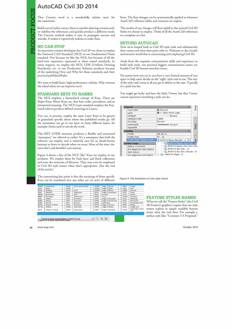
8122019 augi world 2013 10
httpslidepdfcomreaderfullaugi-world-2013-10 4652wwwaugicom October 20
AutoCAD Civil 3D 2014
PRO
DUCT
FOCUS
hat Current word is a wonderfully relative term forthe customizer
Build a set of styles extract them to another drawing rename andor redefine the references and quickly produce a different resulthe Current method makes it easy to propagate success andmistake It makes it repetitively tedious to make fixes
NO CAN STOPAs innovative content developers for Civil 3D we chose to employthe National CAD Standard (NCS) as our fundamental Namestandard Not because we like the NCS but because of all thehard-won experience expressed in these tested standards Inmany respects we employ the NCS UDS (Uniform DrawingStandards) etc in our Production Solution products becauseof the underlying How and Why for those standards and theirpractical published Rules
We want to build faster high-performance vehicles Why reinventthe wheel when we can improve on it
STANDARD KEYS TO NAMEShe NCS employs a hierarchical concept of Keys here areMajor Keys Minor Keys etc that have order precedence and aninterpreted meaning he NCS Layer standard employs the Key-based rules to produce defined meanings to Layers
You can in practice employ the same Layer Keys to be genericor granularly specific about where the published results go Allthe annotation can go to one layer or many different layers forexample Styles andor sets do the work
his KEY CODE structure produces a flexible and structuredldquonamespacerdquo we referred to earlier Itrsquos a namespace that both thesoftware can employ and is relatively easy for us dumb-bunnyhumans to learn to decode when we must Most of the time theusers donrsquot and shouldnrsquot care anyway
Figure 4 shows a few of the NCS ldquolikerdquo Keys we employ in ourproducts We employ them for both layer and block collectionsand even the structure of libraries hey may even be employedin Civil 3D style names when thatrsquos appropriate (See the endof the article)
he customizing key point is that the meanings of these specificKeys can be translated into any other set (or sets) of different
Keys he Key changes can be systematically applied to whatevAutoCAD reference tables and resources we require
he results of any changes will float uphill to the named Civil 3Styles we choose to employ hink of all the AutoCAD referencin a template as a Set
BEYOND AUTOCADNow wersquove looped back to Civil 3D style tools and substantivetheir names and what their parts refer to Welcome to the circuland iterative world that is customizing and employing Civil 3D
Aside from the requisite customization skills and experience build style tools our practical biggest customization issues afrankly Civil 3D human interface issues
No matter how you cut it you have a very limited amount of tespace to help users decide on the ldquorightrdquo style tool to use he teof the style toolrsquos name is all you get to deliver to the user ypicaitrsquos a pick box list
You might get lucky and have the Style Viewer but that Viewcannot represent everything a style can do
FEATURE STYLES NAMESWhat we call the ldquoFeature Stylesrdquo (the Ci3D Featurersquos graphics) require that our stynames explain in simple readable humterms what the tool does For examplesurface style like ldquoContours 1-5 Proposed
Figure 4 Some standard keys
Figure 5 The limitations of user style choice
8122019 augi world 2013 10
httpslidepdfcomreaderfullaugi-world-2013-10 4752October 2013 wwwaugiworldcom
AutoCAD Civil 3D 2014
For the common and most understood features this makes somesense ASCII order rules how named Styles organize Names mustsort that out
Complex graphic features such as Views have a lot more going onldquoMy Standard Profile Viewrdquo doesnrsquot cut it except in a publishingtemplate he style names must be more informative and specificDoes the Profile View include grid lines or not We must recognizethat the engineering data behind what we want to visualize isvariable and the user will have specific needs to get work doneWhen you check a surface you need to see the data in differentways than when the result is published
Choice of style is productive Choice is not contrary to publishingstandards unless you mix the two
LABEL STYLE NAME FACTORSWhen we open the Alignment Label Style collection andorstart to assemble Sets of Label Styles we see any hope of namesimplicity for label styles disappears in a flash
he majority of styles are annotative here are a lot of formsand specific types of them Label Style ype matters he smartcustomizer employs the Label Style Default (LSD) hierarchyexpressed in the oolspacegtgtSettings tab or ignores it and missesthe benefits
Label styles often must have a geometric framework to themItrsquos about ldquoreadabilityrdquo and meaning Whether this label goes upor down or attaches here and not there is critical to annotativeclarity he graphic structure of many data-rich label styles alsofundamentally matters to the stylersquos upgrade stability herersquos
a maintenance cost to pay if you refuse to employ consistentgeometric structures in label styles
CUSTOM USAGECan users see the right data and at the right time Will the useremploy a general alignment parcel or figure line and curve labelHow do they see the difference in a simple list It is easy to misshow ldquoon-the-flyrdquo annotative information negatively or positivelyeffects design time decision making and quality control Peoplewill make things to get the job done Do you fight it or enable ithe Simple Style Rules anyone can learn
THE CIVIL 3D NAMESPACESA Civil 3D style naming convention must be human readablecreate order in the interface and therefore include a rule-basedeasy-to-learn code system that expresses quickly the critical detailso customize we need two namespaces One for the top-end stylesand one for the back-end AutoCAD references In productionprojects we need a third namespace for how we name the featuresbut thatrsquos another story
his client and this project demand these CAD standards specificsAnother client and project demand something different Even ifyou donrsquot believe you regularly face that common problem you
still have to improve the internal production templates themselveshe method and process arenrsquot different
In our project-based production world Civil 3D users andsupervisory staff can always work with the familiar and publishwhat is demanded in a customized publishing template hetwo-pronged project template approach has the added benefit ofpotentially quantifying the costs and real return on investment forthe customization itself
CUSTOMIZE TO PUBLISH ON DEMANDIn practical terms we can change the expressed graphicsmdashthe PlanSet Language (CAD standards) with managed intern level staffEven non-CAD people can see and identify graphic differenceOnly basic AutoCAD and basic spreadsheets skills are requiredfor much of the work if you have a naming plan ldquoChange thatmanhole block to look like this manhole blockrdquo Your ldquothatrdquo mustbe specific
ldquoPublish on demandrdquo capability is a productivity and competitive
advantage but it takes repetitions to develop and practice the skillsWe must endlessly customize Civil 3Dmdashreap the benefits
CIVIL 3D NAME RESOURCEShe Standard Keys the NCS-like AutoCAD reference namespacehe Jump Standards includes the detailed and documented stylenamespace Find them at wwwcadpilotcomresourcesaspx
Excel Cell Formula Script ExampleHerersquos the pseudo code for a typical formula-based layer script thatmakes a layer table with all the details filled in from a cell It createsa series of quote wrapped strings when a column of such cells is
copied and pasted to an ASCII text file
ltLayerCommandgtampCHAR(13)amprdquoSrdquoampCHAR(13)ampltOldLayergtampCHAR(13)amprdquoRrdquoampCHAR(13)ampltNewLayergtampCHAR(13)ampltNewLayergtampCHAR(13)amprdquoCrdquoampCHAR(13)ampltColorgtampCHAR(13)ampCHAR(13)amprdquoLWrdquoampCHAR(13)ampltLineweightgtampCHAR(13)ampCHAR(13)amprdquoPSrdquoampCHAR(13)ampltPlotstylegtampCHAR(13)ampCHAR(13)amprdquoDrdquoampCHAR(13)ampltDescriptiongtampCHAR(13)ampltNewLayergtampCHAR(13)
ench ilghman is President ofMoreCompetency Inc an Autodesk
Developer Partner specializing in in-novative Civil 3D Production Solu-tion products and consulting services
for AutoCAD Civil 3D ench is aregular speaker at Autodesk Univer-sity and AEC industry events on thetopics of technology adoption innova-tion and (his personal favorite) peopleskills He posts on the Get the Jump onCivil 3D blog
8122019 augi world 2013 10
httpslidepdfcomreaderfullaugi-world-2013-10 4852wwwaugicom October 20
Revit MEP 2014
PRO
DUCT
FOCUS
by Todd Shackelfor
W
hen any new technology hits theground there are plenty of false startsand backtracking In time shortcutsare found tricks of the trade are
discovered and best practices are defined So is thecase with Autodeskreg Revitreg even for MEP users his article willoutline a logical roadmap of technical and non-technical mustdorsquos and donrsquot dorsquos for transitioning to Revit MEP From settingexpectations defining goals and plotting in Revit to addressingBIM IPD and VDC the checklist of elements required to helpRevit really work in an office will be covered Every implementationwill come with resistance workflow issues and plenty of headachesbut staying on course and hitting the important milestones alongthe way will help reduce stress of something akin to the craziestfamily trip ever
FIRST CONSIDERATIONS ndash SOFTWAREOne might think it is all about Revit he truth is that Revit reallywants to act as a central location for data that is constantly on themove Much like a smartphone leverages the power of thousandsof applications Revit plugs into workflows with more than a fewAutodesk programs as well as a host of third-party programs hesimple fact that the Building Design Suite comes with so manyvaried applications is a pretty big hint that Revit wants to play ona team Firms need to look at their processes from a high level andlook for the best workflows and programs for the team
FIRST CONSIDERATIONS ndash HARDWAREEvaluate the PCs and know what their capabilities are anknow what Revit requires Search Autodeskrsquos website for systerequirements for Revit products Requirements for three tieof deployment are listed for systems covering an entry-levconfiguration a balanced performance configuration and performance configuration Certified and supported graphi
hardware is also accessible from this page he non-hardwasavvy should seek input from an I professional Revit cannand will not perform on outdated or entry-level PCs and thperson leading the implementation usually takes the blame wheexpectations fall short Best advice is overkill it on hardware Whseems over the top today is inadequate in a year
FIRST CONSIDERATIONS ndash TRAININGhere is no way to get around the fact that training will need tbe done Even if every person in the firm has already used Revtraining on using Revit company standards must still take plachere are many ways to deliver training An in-house expe
TransitionRoadmap
8122019 augi world 2013 10
httpslidepdfcomreaderfullaugi-world-2013-10 4952October 2013 wwwaugiworldcom
Revit MEP 2014
can provide just-in-time all the time Autodesk resellers andconsultants typically provide three- to five-day immersion trainingand short- to long-term consulting here are countless web-based training optionsmdashfree and paid Community colleges thatoffer Revit training usually require a final project that will putstudents through the paces and better entrench the
knowledge and skills
On the down side Revit MEP-specific classes areall but impossible to find Lastly the extreme go-getter can buy a book and learn on the job In realityeveryone learns differently and being preparedto leverage all these types of training is the bestsolution People will gravitate to the solution thatworks best for them when it is provided
FIRST CONSIDERATIONS ndash
LINE UP YOUR DUCTS (UGH hellip
DUCKS)Set appropriate goals based on the size of thefirm Small medium and large firms will havedrastically different goals and timelines It mightseem odd but small firms have the upper hand inadopting new technologies and processes hinkabout it What is easiermdashgetting 3 people toagree or 300 Recognize that an AE firm will havecompletely different goals and processes than a solely MEP firmDuring any shift in process be prepared to support the old andnew at the same time and sometimes in the same project hiswill mean keeping symbols in Revit as close as possible to symbols
in AutoCADreg Consider how quality reviews are done and clientexpectations When things look different it is an impediment tochange Minimizing the impediments will help tremendously
All that being said communication is the real key to most everyprojectrsquos success It is important keep information flowing upand down the chain and set the expectations early Some criticalexpectations for this type of implementation are that things will gowrong things will take longer things will look different things willhave to change and things will continue to evolve Remind usersand management of the progress they have been made by trackingand documenting incremental goals
With a general direction and expectations set itrsquos time to get morespecific about the journey his trip is a long one and a phasedapproach is best Firms can tailor the following phasing to suitindividual needs his example has four phasesmdasheach with itsown goals building off the previous phases
Phase 1 - Goals1 Create construction documents2 Improved collaboration3 Interference mitigationo obtain these goals the following Revit items need to be addressedhe first group addresses the goal of good construction documentshe second group deals with process and keeping things standardhe space available in this article doesnrsquot allow for ldquoHow torsquosrdquo foreach item but each is well documented in the Revit help pageand all over the Internet Get a couple points of view and marrythe possibilities to the culture and needs of the firm in question
bull Line styles createdbull Fonts set for plan text titles title blocks tags and everything
elsebull Object styles ndash Define the weight color tone and transparency
of everything bull Incorporation of standard detailsbull Browser organization ndash Decide how you want to see views
organizedbull Filters ndash Know if you need standard filters and create them
ahead of timebull Phasesbull View templatesbull Project templatebull Duct Stylesbull Pipe stylesbull Family creation
Figure 1
Figure 2
8122019 augi world 2013 10
httpslidepdfcomreaderfullaugi-world-2013-10 5052
8122019 augi world 2013 10
httpslidepdfcomreaderfullaugi-world-2013-10 5152October 2013 wwwaugiworldcom
Inside Track
CSCrsquos Integratorhttpwwwcscworldcom
Integrator is a tool that allows you to synchronize structural designscreated in CSCrsquos Fastrak Building Designer (steel building designsoftware) and Orion (structural concrete building design software)with Autodeskreg Revitreg 2014
ldquoLeading structural software provider CSC has released a new versionof Integrator its market leading Structural BIM integration softwarefor synchronizing code-compliant models produced in CSCrsquos buildingdesign software Fastrak and Orion with Autodeskreg Revitreg Nowfully compatible with Autodesk Revit 2014 structural engineers andtechnicians have even greater control during the integration process
Using Integrator full and part models can be synchronized betweenFastrak or Orion and Autodesk Revit with the ability to manageadded deleted and modified members and their associated
design datardquo
BiMTOOLShttpwwwsofistikcom
BiMOOLS is a set of productivity tools that are designed forAutodeskreg Revitreg 2014 Te plug-in can be installed from theAutodesk Exchange Apps store
ldquoTe first international version of the SOFiSiK BiMOOLS isnow available SOFiSiK BiMOOLS is a collection of free tools forAutodeskreg Revitreg Structure to enhance the productivity up to 50Te features range from easy font type substitution and automaticgeneration of dimensional lines over the automatic positioning ofstructural elements to the comprehensive Family Creator to generatefamilies of eg beams braces and columns for optimal communicationwith FE analysis tools like the SOFiSiK softwarerdquo
Find further information and download links for Revit 2012 and
2013 on the dedicated BiMOOLS website
Autodesk AutoCAD 360 21httpswwwautocad360com
Autodeskreg AutoCADreg 360 is a mobile and web-based application that allows you to view editand share drawing files created with AutoCADand AutoCAD-based products Te mobile appis available from the Apple iunes App Store andGoogle Play Store
ldquoAutoCAD 360 is a free easy-to-use drawing and drafting mobileapp that allows you to view edit and share AutoCAD drawingsmdashanytime anywhere Simplify site visits and fieldwork with powerfuldesign review and markup toolsmdashavailable online and offline
Seamlessly share drawings with others across desktop web andmobile devices Easily access drawings from web browsers using
the free companion AutoCAD 360 web app AutoCAD 360Pro subscription plans further expand the functionality of
the app bringing additional capabilities to the fieldrdquo
Te updates that are in this latest release arebull Stunning high-resolution drawings display
via full retina supportbull Better display through improved PDF
supportbull Easy switching between metric and imperial
unitsbull Saves time with faster app loading bull Improved collaboration through in-app
notifications and streamlined sharing bull New properties for Properties Palette
(Pro version)
AUGIWorldbrings
you recentdevelopmentsin Autodeskand AEC-relatedsoftwareitems
Until next issue
If you have some news to share with us for future issues please let usknow Likewise if you are a user of a featured product or news itemand would like to write a review we want to know
By Lee Ambrosius
8122019 augi world 2013 10
httpslidepdfcomreaderfullaugi-world-2013-10 5252
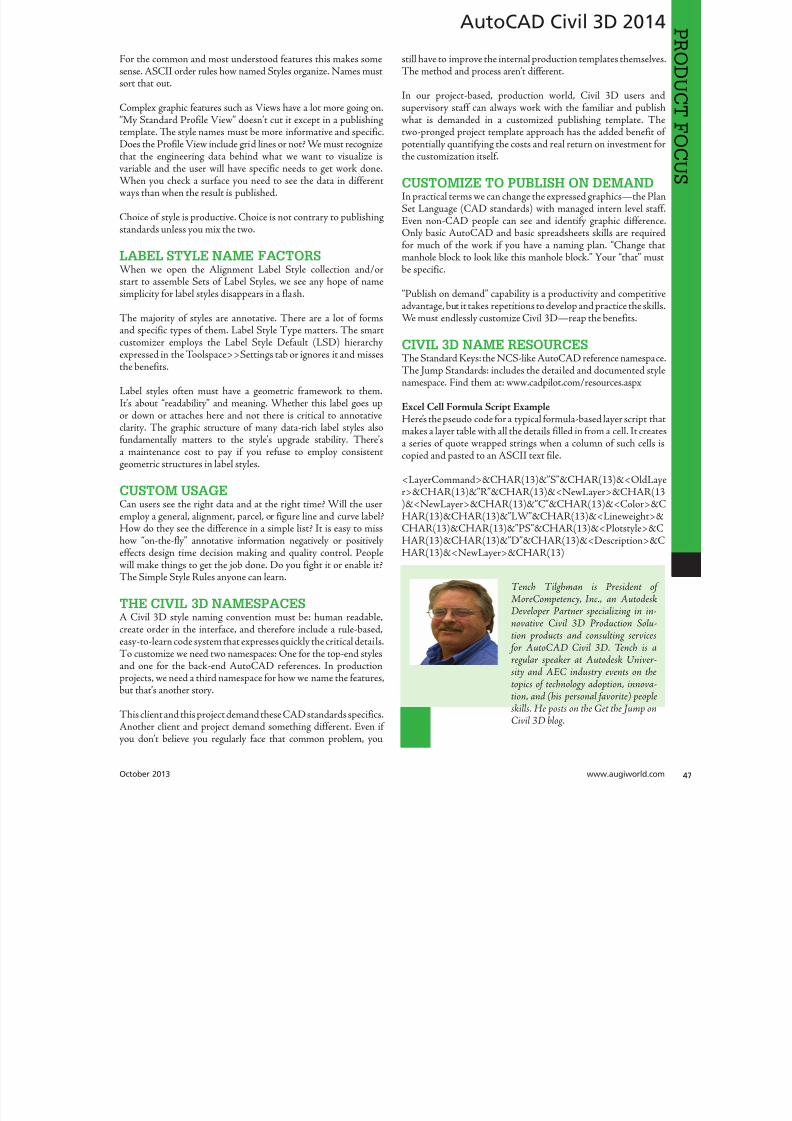
8122019 augi world 2013 10
httpslidepdfcomreaderfullaugi-world-2013-10 4852wwwaugicom October 20
Revit MEP 2014
PRO
DUCT
FOCUS
by Todd Shackelfor
W
hen any new technology hits theground there are plenty of false startsand backtracking In time shortcutsare found tricks of the trade are
discovered and best practices are defined So is thecase with Autodeskreg Revitreg even for MEP users his article willoutline a logical roadmap of technical and non-technical mustdorsquos and donrsquot dorsquos for transitioning to Revit MEP From settingexpectations defining goals and plotting in Revit to addressingBIM IPD and VDC the checklist of elements required to helpRevit really work in an office will be covered Every implementationwill come with resistance workflow issues and plenty of headachesbut staying on course and hitting the important milestones alongthe way will help reduce stress of something akin to the craziestfamily trip ever
FIRST CONSIDERATIONS ndash SOFTWAREOne might think it is all about Revit he truth is that Revit reallywants to act as a central location for data that is constantly on themove Much like a smartphone leverages the power of thousandsof applications Revit plugs into workflows with more than a fewAutodesk programs as well as a host of third-party programs hesimple fact that the Building Design Suite comes with so manyvaried applications is a pretty big hint that Revit wants to play ona team Firms need to look at their processes from a high level andlook for the best workflows and programs for the team
FIRST CONSIDERATIONS ndash HARDWAREEvaluate the PCs and know what their capabilities are anknow what Revit requires Search Autodeskrsquos website for systerequirements for Revit products Requirements for three tieof deployment are listed for systems covering an entry-levconfiguration a balanced performance configuration and performance configuration Certified and supported graphi
hardware is also accessible from this page he non-hardwasavvy should seek input from an I professional Revit cannand will not perform on outdated or entry-level PCs and thperson leading the implementation usually takes the blame wheexpectations fall short Best advice is overkill it on hardware Whseems over the top today is inadequate in a year
FIRST CONSIDERATIONS ndash TRAININGhere is no way to get around the fact that training will need tbe done Even if every person in the firm has already used Revtraining on using Revit company standards must still take plachere are many ways to deliver training An in-house expe
TransitionRoadmap
8122019 augi world 2013 10
httpslidepdfcomreaderfullaugi-world-2013-10 4952October 2013 wwwaugiworldcom
Revit MEP 2014
can provide just-in-time all the time Autodesk resellers andconsultants typically provide three- to five-day immersion trainingand short- to long-term consulting here are countless web-based training optionsmdashfree and paid Community colleges thatoffer Revit training usually require a final project that will putstudents through the paces and better entrench the
knowledge and skills
On the down side Revit MEP-specific classes areall but impossible to find Lastly the extreme go-getter can buy a book and learn on the job In realityeveryone learns differently and being preparedto leverage all these types of training is the bestsolution People will gravitate to the solution thatworks best for them when it is provided
FIRST CONSIDERATIONS ndash
LINE UP YOUR DUCTS (UGH hellip
DUCKS)Set appropriate goals based on the size of thefirm Small medium and large firms will havedrastically different goals and timelines It mightseem odd but small firms have the upper hand inadopting new technologies and processes hinkabout it What is easiermdashgetting 3 people toagree or 300 Recognize that an AE firm will havecompletely different goals and processes than a solely MEP firmDuring any shift in process be prepared to support the old andnew at the same time and sometimes in the same project hiswill mean keeping symbols in Revit as close as possible to symbols
in AutoCADreg Consider how quality reviews are done and clientexpectations When things look different it is an impediment tochange Minimizing the impediments will help tremendously
All that being said communication is the real key to most everyprojectrsquos success It is important keep information flowing upand down the chain and set the expectations early Some criticalexpectations for this type of implementation are that things will gowrong things will take longer things will look different things willhave to change and things will continue to evolve Remind usersand management of the progress they have been made by trackingand documenting incremental goals
With a general direction and expectations set itrsquos time to get morespecific about the journey his trip is a long one and a phasedapproach is best Firms can tailor the following phasing to suitindividual needs his example has four phasesmdasheach with itsown goals building off the previous phases
Phase 1 - Goals1 Create construction documents2 Improved collaboration3 Interference mitigationo obtain these goals the following Revit items need to be addressedhe first group addresses the goal of good construction documentshe second group deals with process and keeping things standardhe space available in this article doesnrsquot allow for ldquoHow torsquosrdquo foreach item but each is well documented in the Revit help pageand all over the Internet Get a couple points of view and marrythe possibilities to the culture and needs of the firm in question
bull Line styles createdbull Fonts set for plan text titles title blocks tags and everything
elsebull Object styles ndash Define the weight color tone and transparency
of everything bull Incorporation of standard detailsbull Browser organization ndash Decide how you want to see views
organizedbull Filters ndash Know if you need standard filters and create them
ahead of timebull Phasesbull View templatesbull Project templatebull Duct Stylesbull Pipe stylesbull Family creation
Figure 1
Figure 2
8122019 augi world 2013 10
httpslidepdfcomreaderfullaugi-world-2013-10 5052
8122019 augi world 2013 10
httpslidepdfcomreaderfullaugi-world-2013-10 5152October 2013 wwwaugiworldcom
Inside Track
CSCrsquos Integratorhttpwwwcscworldcom
Integrator is a tool that allows you to synchronize structural designscreated in CSCrsquos Fastrak Building Designer (steel building designsoftware) and Orion (structural concrete building design software)with Autodeskreg Revitreg 2014
ldquoLeading structural software provider CSC has released a new versionof Integrator its market leading Structural BIM integration softwarefor synchronizing code-compliant models produced in CSCrsquos buildingdesign software Fastrak and Orion with Autodeskreg Revitreg Nowfully compatible with Autodesk Revit 2014 structural engineers andtechnicians have even greater control during the integration process
Using Integrator full and part models can be synchronized betweenFastrak or Orion and Autodesk Revit with the ability to manageadded deleted and modified members and their associated
design datardquo
BiMTOOLShttpwwwsofistikcom
BiMOOLS is a set of productivity tools that are designed forAutodeskreg Revitreg 2014 Te plug-in can be installed from theAutodesk Exchange Apps store
ldquoTe first international version of the SOFiSiK BiMOOLS isnow available SOFiSiK BiMOOLS is a collection of free tools forAutodeskreg Revitreg Structure to enhance the productivity up to 50Te features range from easy font type substitution and automaticgeneration of dimensional lines over the automatic positioning ofstructural elements to the comprehensive Family Creator to generatefamilies of eg beams braces and columns for optimal communicationwith FE analysis tools like the SOFiSiK softwarerdquo
Find further information and download links for Revit 2012 and
2013 on the dedicated BiMOOLS website
Autodesk AutoCAD 360 21httpswwwautocad360com
Autodeskreg AutoCADreg 360 is a mobile and web-based application that allows you to view editand share drawing files created with AutoCADand AutoCAD-based products Te mobile appis available from the Apple iunes App Store andGoogle Play Store
ldquoAutoCAD 360 is a free easy-to-use drawing and drafting mobileapp that allows you to view edit and share AutoCAD drawingsmdashanytime anywhere Simplify site visits and fieldwork with powerfuldesign review and markup toolsmdashavailable online and offline
Seamlessly share drawings with others across desktop web andmobile devices Easily access drawings from web browsers using
the free companion AutoCAD 360 web app AutoCAD 360Pro subscription plans further expand the functionality of
the app bringing additional capabilities to the fieldrdquo
Te updates that are in this latest release arebull Stunning high-resolution drawings display
via full retina supportbull Better display through improved PDF
supportbull Easy switching between metric and imperial
unitsbull Saves time with faster app loading bull Improved collaboration through in-app
notifications and streamlined sharing bull New properties for Properties Palette
(Pro version)
AUGIWorldbrings
you recentdevelopmentsin Autodeskand AEC-relatedsoftwareitems
Until next issue
If you have some news to share with us for future issues please let usknow Likewise if you are a user of a featured product or news itemand would like to write a review we want to know
By Lee Ambrosius
8122019 augi world 2013 10
httpslidepdfcomreaderfullaugi-world-2013-10 5252
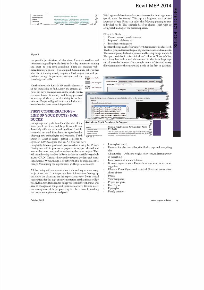
8122019 augi world 2013 10
httpslidepdfcomreaderfullaugi-world-2013-10 4952October 2013 wwwaugiworldcom
Revit MEP 2014
can provide just-in-time all the time Autodesk resellers andconsultants typically provide three- to five-day immersion trainingand short- to long-term consulting here are countless web-based training optionsmdashfree and paid Community colleges thatoffer Revit training usually require a final project that will putstudents through the paces and better entrench the
knowledge and skills
On the down side Revit MEP-specific classes areall but impossible to find Lastly the extreme go-getter can buy a book and learn on the job In realityeveryone learns differently and being preparedto leverage all these types of training is the bestsolution People will gravitate to the solution thatworks best for them when it is provided
FIRST CONSIDERATIONS ndash
LINE UP YOUR DUCTS (UGH hellip
DUCKS)Set appropriate goals based on the size of thefirm Small medium and large firms will havedrastically different goals and timelines It mightseem odd but small firms have the upper hand inadopting new technologies and processes hinkabout it What is easiermdashgetting 3 people toagree or 300 Recognize that an AE firm will havecompletely different goals and processes than a solely MEP firmDuring any shift in process be prepared to support the old andnew at the same time and sometimes in the same project hiswill mean keeping symbols in Revit as close as possible to symbols
in AutoCADreg Consider how quality reviews are done and clientexpectations When things look different it is an impediment tochange Minimizing the impediments will help tremendously
All that being said communication is the real key to most everyprojectrsquos success It is important keep information flowing upand down the chain and set the expectations early Some criticalexpectations for this type of implementation are that things will gowrong things will take longer things will look different things willhave to change and things will continue to evolve Remind usersand management of the progress they have been made by trackingand documenting incremental goals
With a general direction and expectations set itrsquos time to get morespecific about the journey his trip is a long one and a phasedapproach is best Firms can tailor the following phasing to suitindividual needs his example has four phasesmdasheach with itsown goals building off the previous phases
Phase 1 - Goals1 Create construction documents2 Improved collaboration3 Interference mitigationo obtain these goals the following Revit items need to be addressedhe first group addresses the goal of good construction documentshe second group deals with process and keeping things standardhe space available in this article doesnrsquot allow for ldquoHow torsquosrdquo foreach item but each is well documented in the Revit help pageand all over the Internet Get a couple points of view and marrythe possibilities to the culture and needs of the firm in question
bull Line styles createdbull Fonts set for plan text titles title blocks tags and everything
elsebull Object styles ndash Define the weight color tone and transparency
of everything bull Incorporation of standard detailsbull Browser organization ndash Decide how you want to see views
organizedbull Filters ndash Know if you need standard filters and create them
ahead of timebull Phasesbull View templatesbull Project templatebull Duct Stylesbull Pipe stylesbull Family creation
Figure 1
Figure 2
8122019 augi world 2013 10
httpslidepdfcomreaderfullaugi-world-2013-10 5052
8122019 augi world 2013 10
httpslidepdfcomreaderfullaugi-world-2013-10 5152October 2013 wwwaugiworldcom
Inside Track
CSCrsquos Integratorhttpwwwcscworldcom
Integrator is a tool that allows you to synchronize structural designscreated in CSCrsquos Fastrak Building Designer (steel building designsoftware) and Orion (structural concrete building design software)with Autodeskreg Revitreg 2014
ldquoLeading structural software provider CSC has released a new versionof Integrator its market leading Structural BIM integration softwarefor synchronizing code-compliant models produced in CSCrsquos buildingdesign software Fastrak and Orion with Autodeskreg Revitreg Nowfully compatible with Autodesk Revit 2014 structural engineers andtechnicians have even greater control during the integration process
Using Integrator full and part models can be synchronized betweenFastrak or Orion and Autodesk Revit with the ability to manageadded deleted and modified members and their associated
design datardquo
BiMTOOLShttpwwwsofistikcom
BiMOOLS is a set of productivity tools that are designed forAutodeskreg Revitreg 2014 Te plug-in can be installed from theAutodesk Exchange Apps store
ldquoTe first international version of the SOFiSiK BiMOOLS isnow available SOFiSiK BiMOOLS is a collection of free tools forAutodeskreg Revitreg Structure to enhance the productivity up to 50Te features range from easy font type substitution and automaticgeneration of dimensional lines over the automatic positioning ofstructural elements to the comprehensive Family Creator to generatefamilies of eg beams braces and columns for optimal communicationwith FE analysis tools like the SOFiSiK softwarerdquo
Find further information and download links for Revit 2012 and
2013 on the dedicated BiMOOLS website
Autodesk AutoCAD 360 21httpswwwautocad360com
Autodeskreg AutoCADreg 360 is a mobile and web-based application that allows you to view editand share drawing files created with AutoCADand AutoCAD-based products Te mobile appis available from the Apple iunes App Store andGoogle Play Store
ldquoAutoCAD 360 is a free easy-to-use drawing and drafting mobileapp that allows you to view edit and share AutoCAD drawingsmdashanytime anywhere Simplify site visits and fieldwork with powerfuldesign review and markup toolsmdashavailable online and offline
Seamlessly share drawings with others across desktop web andmobile devices Easily access drawings from web browsers using
the free companion AutoCAD 360 web app AutoCAD 360Pro subscription plans further expand the functionality of
the app bringing additional capabilities to the fieldrdquo
Te updates that are in this latest release arebull Stunning high-resolution drawings display
via full retina supportbull Better display through improved PDF
supportbull Easy switching between metric and imperial
unitsbull Saves time with faster app loading bull Improved collaboration through in-app
notifications and streamlined sharing bull New properties for Properties Palette
(Pro version)
AUGIWorldbrings
you recentdevelopmentsin Autodeskand AEC-relatedsoftwareitems
Until next issue
If you have some news to share with us for future issues please let usknow Likewise if you are a user of a featured product or news itemand would like to write a review we want to know
By Lee Ambrosius
8122019 augi world 2013 10
httpslidepdfcomreaderfullaugi-world-2013-10 5252
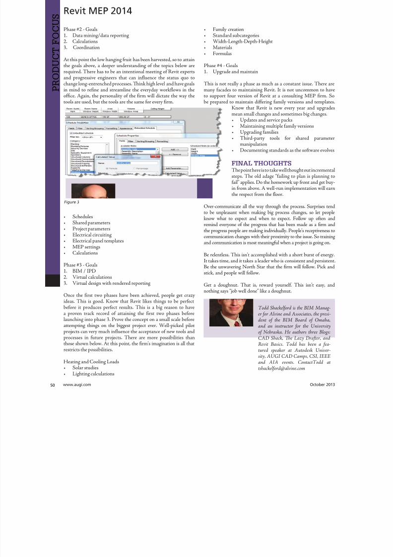
8122019 augi world 2013 10
httpslidepdfcomreaderfullaugi-world-2013-10 5252