Embed Size (px)
Citation preview

Audio~ precislon reg Testing for Optimal Results System Two Cascade Plus
Audio Test and Measurement System
Unmatched Performance
-
------Turn on High Performance Testing with System Two Cascade Plus
Unparalleled Precision
Low Distortion Analog System THD+N 20kHz BW -112dB
Typical worst case harmonic lt -130dB
Digital DistortionSpurious Products -160dB
High Analog Bandwidth Signal generation to 200kHz
Measurements to 500kHz
FFTs and Multitone analysis to 120kHz
Low Noise 22-22kHz lt -118dBu
A-weighted lt -124dBu
Flat Response 20-20kHz typically plusmn0003dB
low Crosstalk Input lt -140dB
Output lt -120dB
Low Jitter Generator lt 08n5
Analyzer lt 16n5
FFT Acquisitions up to 4MSample5 (gt 1 minute 48kHz)
Audio Precisions System Two Cascade Plus a PC-controlled audio test and measure me nt
system is the newest generation of the companys award-winning System Two Air ady
the recognized worldwide standard for design and test of audio equipment Cascade Plus
brings the improved distortion and noise specifications required to test the latest
advances in converter technology
True Dual Domain architecture provides uncompromised performance for both anal 9
and digital signals and the DSP-based analysis techniques offer a wide array of high
speed precise measurements
bull Unparalleled Precision
bull PC-Control and Programmability
bull Unparalleled Speed
bull Comprehensive Digital Interface Testing
bull Flexible Configuration Options
System Two Cascade Plus Proven reliable high performance from the industrys
preeminent audio test and measurement company
Allaog System THON 20kHz BIV middot 12dB
PC Contre
APWIN is a CI
real-time intE
of System Tw
development
testing
Operati ng on
Systems it pi
interface cap
variety of tes
graphs and d
test data ani
limits
The flexi ble p
the configura
of uses from
automated pI
bull APWIN inel
advanced
programmir
capabilitie
complete
control of t
instrument
the user
interface vi
OLE The fu
programmir
branched tf
step-by-ste
bull Learn Mode
convenient
automated
without anI
I
~ - ~- qshy
j
I j - ~ bull bullbull~ ~_ n bull II Ie - bull ~_ -u _ _
0 - middottTgt _
- J
e Plus
easurement
10 Already
ascade Plus
latest
1 analog
of high
rys
PC Control and Programmability APWIN
APWIN is a comprehensive PC-based
real-time interface for control and display
of System Two Cascade Plus and a
development system for automated audio
testing
Operating on all Windows reg Operating
Systems it provides a graphical user
interface capable of generating a wide
variety of test signals displaying readings
graphs and data tables storing setups and
test data and comparing data to test
limits
The flexible panel-based architecture offers
the configurability to address a wide range
of uses from benchtop engineering to
automated production test
bull APWIN includes ~- -=shyadvanced
programming
capabilities for
complete
control of the d Procedure Edllor uciliotes procedureInstrument an 0110 ond vcriJiwilon rrrcludrng the user ltltp all( Irace morle
interface via
OLE The fully functioned BASIC
programming language supports complex
branched test procedures as well as simpler
step-by-step routines
bull Learn Mode provides a fast and
convenient way to generate
automated test procedures
without any programming experience
The graphical dialog
editor enables drag and
drop design of custom
bull APWIN conforms to the standards of
Microsoft Windowsreg allowing graphs and
data to be directly pasted in applications
bull
user interfaces with
seamless integration
into the BASIC
procedure editor
bull The complete OLE
command
structure is
accessible to
Visual Basic
enabling the
programmer to (onvenient Object Browser assists integrate System inlegfO(ron of commanrls and
cone ltynlax Chin macros Two Cascade Plus
with a wide variety
of other equipment and applications
-iP Basic Dialog Edilol O(OIlS creation oJ professional user inre1nclt2 ponels I~ilhrn plocedvre
ra=-shy
like Word and Excel
bull Test setups test data and graphs can be
exchanged with co-workers by email to
quickly duplicate test results study test
data or publish reports regardless of
location
bull The GPIB option offers an
IEEE-488 interface for
compatibility with other
automated test instruments
measurements in as little as
--= - in speed over normal RMS
Unparalleled Speed Compre
System Two Cascade Plus offers an array of
powerful time-saving tools to speed your
testi ng requi rements
Synchronous Multitone Testing provides
response distortion noi se crosstalk and
phase measurements from a single
sub-second acquisition The program
material-like multi-sinewave stimulus can
be tailored to a wide variety of high speed
testing applications and the synchronous
analysis provides the necessary selectivity
to measure low frequencie s and noise in
the presence of signal
The Fast RMS Detector speeds sine wave
sweeps by making
measurements
Hnrmomt selecton mnllO Dnd grOIII af indiv idual ham(gtIIir IImplitud~ velu~ iqtJInq
Emmple oj (htgt l In hamre1 pili amdcrs t middot Pf~IJ Jflquency f roriul ed [IDill (I gIl UflJCIOI~ SffO( mulil)(1e lesl 1701
The Dual-Channel Harmonic Distortion
Analyzer can simultaneously measure
the fundamental and up to four individual
harmonics Sweeps using this analyzer
can rapidly characterize frequency or
amplitude dependent distortion
mechanisms
A sophisticated data settling algorithm
allows the engineer to optimize the
tradeoff between testing speed and
measurement accuracy
Individual settling parameters are stored
for every available measurement
LOlldspEaler lmpulse flesronse sholl IIlg 66 mlflisecond lieloy 10 mpuL reobull
Quasi-anechoic Measurements of
transducers and acoustics using Maximum
Length Sequence (MLS) noi se signals
produce impulse frequency and phase
response graphs in less than a second
Extensive Library of noise weighting and
band-limiting filters allow noise
measu rements to virtually any international
standard User-defined software-implemented
filters can be created and downloaded by a
supplied utility
Cascade P
Signal An
characteri
All digital
sample ra
Jitter- r jitter amp
waveform
spectrum
amplitude
and ampli
pu lse stre
on the ree
audio sigr
Eye Patte
oscilosco
pulse stre
computed
cells The
quick che
signal-toshy
times ane
5elective(y In) lonmiddotous impairl IiiI digital sgl ~sl d~ce
algorithm
~ the
and
lTe stored
t
1 66
of
Ma ximum
gnals
I phase
econd
hting and
nternationa l
mplemented
oaded by a
Comprehensive Digital Interface Testing
Cascade Plus Digital IO capabilities combined with its Digital
Signal Analyzer allow complete measurement and
characterization of digital interface pulse streams
All digital I O capabilities are functional over the full range of
sample rates from 8 kHz to over 200 kHz
Jitter- Measure the peak or average
jitter amplitude view the jitter
waveform or display the jitter
spectrum or a histogram of the jitter
amplitude Add jitter of various types
and amplitudes to the generated
pulse stream and measu re the effect
on the receiver and the resulting
audio signal
Eye Patterns are a triggered
oscilloscope view of the minimum
pulse stream amplitude vs time
computed over thousands of data
cells The eye openi ng provides a
quick check of signal amplitude
signal-to-noise ratio ri se and fall
times and jitter
Ipm - --~ --~ =~f r~ c
-- -- 9~ r~( tllUlI 1 r~
lertely inject inous impairmeHf5 W L digltol lignO IO ( dev(
Fully (hnmLlerize J 5tHiai dryitnlilit ~rr~am meillur QmiddotefOllrs Pye- fJlttiEffnj SJc(flJm s olld rlltDgrO[ll lIJ $nOWH by lhe~e nme graph
The introduction of impairments to the
digital interface pulse stream allows
evaluation of the susceptibility of receivers
to sub-standard signals Variable impairment
capabilities include sample rate pulse
amplitude pulse rise and fall times long
cable simulation addition of normal mode
noise or common mode signals and
controlled amounts of jitter
~ rJ ~ II - -
Digrtal inputOulput p~eI
The Digital InputOutput panel includes
input and output provision for single XLR
connector 48 amp 96 kHz sample rate
professional formats dual connector 96
amp 192 kHz rates as well as input
switching for 4 channels of AESEBU
audio at 48kHz It also provides BNC and
optical connections for 48 and 96 kHz
unbalanced and consumer formats
Rem pnel connectllJlIS
Histograms display the probability
distribution of pulse stream parameters
like timing Uitter) amplitude sample
rate and bit width
The interface signal and the jitter waveform can be viewed either in the
time domain (osci lloscope view) or the
frequency domain (FFT spectrum)
Complete control and display
of interface information
including sample rate
amplitude active data bits
error flags and status bytes
displayed in both hex and
high-level Engli sh terminology
[ampelete Slntus Bit informntioll in 2lhet Consumer 01 Profess 011(1 forllJoL
OSP Audio AnalyzerSystem Two Cascade Plus Specification Summary WidebiJlld lveUAmplitl Frequency Range Hi9t1 pa~ s Fitte rs
low pJSs FiltersANALOG SIGNAL OUTPUTS (except SYS-170D) OTHER SIGNALS B P middot u= = -_~ ndf =df middot =SSAcmpitu nctJ n __---== ____ -- - - ------ 10 Hz to 200 kHzANAlOGSIGNAlG[HRATO~Rri--------- A~----W t - 1 dM- mI - I----- - -- Tun ing Range (f ) We ighting F ilter~ =====--c---_ _____ ___ _ _ ___ _ IY ==u=o Bandpass Response 13-octave class 11 (4- pote) 2 dB al~= rm =----------------__c=--
LN Distortioll Sine Waft SignClI De termined by the associated fi le 05 f~ and 20 fa==_ _ _ ---------____ ___ specified in the panel drop-down box Narrow Bond AmpliludFrequency Range 10 Hz to 204 kHz Bandrejed Amplitude function
Frequency RangeFlequency Accuracy cM===lgtng= SeqUI IMl__bull___~_ _______ TunIng Range (f) ]0 Hz to 200 kH z =middotmum = Il1c == SI Fitter ShapeHigh-accuracy mode Seque nce~ 4 pink 4 whit e Tum ~g Ac curacy plusmn2 ~o
Fa st mode Speciitl Signals Bandreject RlS ponse TypicaUy middot3 dB at 073 to amp 13 7 to HIO+H MeilSul1me111s Amplit ude Range middot20 dB at fo 1 10tyo fundamental Ra MgBalanced lt10 IIV to 2666 Vrms (+30 7 dBuj Polarity Asymmetric middotaeform for polarity middot40 dB at fo t2 5 Hig h pass Filte rsUnbalanced lt1 0 IV to 13 33 Vrms [-t247 dBu] testing15 kHz at 30 kHz bandwidth20 Accuracy to l dB 20 Hz-120 kHz
low pass M(tersAmplitude Accuracy 01 [iO 06 dB] at 1 kHz Hz to 30 kH z at 60 kHz bandwidth (exduding 05 f to 20 fQ) We ig hti ng FiltflliAmplitude Reso lution Pass Thru Accepts signal at rear panel Reference Residual Noise same as Ampll tude Function
VMIII 150lVrms OOOl dB Input with sa mple rate from 27 kH z to THD+H functionVIlI lt150 Vrms 005 mV rm s 54 kHz fqutncy Mil5Uremen
flatnfss (I kHz ref) SquartwiIYt Fu ndamental Range 10 Hz to 200 kHz Raqe10 Hz-200 kHz - 021 -Ol dB ----7-------- - ------- --- Accuracy plusmn0 3 dB 20 HZ-120 kHz ha rmonics Accuracy
Residual Distort ion frequen cy Ra nge 20 liz to 15 1 Hz Measurement Bandwidth at I kHz Typica lly 0000] [-130 dBc] lt10 22 100 or 400 Hz
Hoise Signal ~j~ ~~ Resolut ion 20 Hz - 20 kH z Typ ically 0001 [- 120 dBc] 22k lOk BO k or 500 kHz
Residual THD+N True randoHl white option filte rs are also funct ional at 1 kHz (0 00025~ + 10 ~VI 1-11 2 dB] OUIPulC=hara=c=te=rls=li=CS~---------------- Residual THO-t N Ouasi-Anecholc ACQusl
22 kHz BW ( alid only (or analyzer at 1 kHz (000025~o + 10 V) [middot112 dB] SignaL inputs 85 Vrms) So urce Configuration Selectable balanced unbalanced or 22 kHz BW (vatid only (or analyzer
20 Hz-20 kHz (0 000l2 + 1 mV) 22 kHz BW CMTST (common mode test) inputs 85 Vrms) Frequency Ra nge[-110 dB] (0 0005 + 1 mV) 80 kHz 20 Hz-20 kHz (0 000321(1 + 10 IIV)Source Impedances Frequency Rlsolut i BW [-106 dB] Balanced or CMTST 40 n (il 0) 150 fl (2 00 n wilh 22 kHz BW (-110 dB) Acquisition Lengthoption E URn ( bull I OJ or 600 n (00005 + 20 IVI
SMPJ[ lor DI NI Tst Signols (ilO) 80 kHz BW [-106 dB Mul1ilone Analyzer (F
If Tone- 40 5060 70 100 115 2S0 or Me tls urementsUn balanced 200 (plusmnI 0) or 600 n (gt3 [1) (000 101gt middott 60IIV) 500 Hz all 1 5 Max Outpul Power 500 kHz BW 1-100 dB]
HFTone Ra nge 2 kHz-200 kHz Balan(ed +301 dBm into 600 n (Rs 40 0) 10 Hz-l00 kHz (00040 0 -t 60iVI Mix Ratio 41 or 1 I (I fHf ) Unbalanced +244 dBm into 600 n (R = 20 0) 500 kHz BW [-88 dB
Output Related Crosstalk Minimum Input 5 mV for spedfied accuracy usa ble to Frequency Resoluti (elf and Of0Tesl Sigftills 10 Hzmiddot20 kHz -120 dB or 5 mV whi chever is greater lt100 IIV with fixed notch tuning OIHerence frequ ency 80 100 120 140 200 2~0 500 or 20 kHz-l00 kHz -106 dB or 10mV whic he ve r is greater IMO MEASUREMENTS jlh oplion IMO~
1 kHz allI5~ =~===___=___________ Di stortion Center frequency 45 kHz-200 kHz ANALOG ANALYZER (except SYS-170D) S-MPT~E~IDINI~IM fucti~-_ _ --_-7--_---7-=--=_-D~ n onDIM (orTIMI Jest Signills An~alOgln=putCharac~te-rlst=iCS~----------- Test Signal COlllpa tlbih ty Any combinat ion of 40-250 Hz elF) DIGITAL SIGNAL GEl ===c-==-------c-----=--~--=------- --c--________ __---__~---- and 2 kHz-- l00 kHz (HF ) tones mixed Squarewave frequency 315 kHz (DIM-30 and OlM-I00) lnput Range 40 mV to 16) V In 602 dB steps in any ratio from 01 to 81 (IFHF) DIGIT Al OUTPUT CHAR
296 kHz (DIM-B) both plusmn10f0 Maximum Rated Input 230 Vpk 160 Vrm s (de to 20 kHz ) Output Formats Sinewa e Frequency 15 kHz (D IM -3D and DIM-l00) overload protected in all ranges (elf and OFO IMD functi ons
14 kHz (DIM-B) Input Impedance Test Signal Compat ibil ity Any combination of equa l amplit ude Balanced (each side) Nominally 100 5ltW tones from 4 kHz - l Oa kHz spaced
Sine Burst Unbalanced Nomi nally 100 kW 80 Hz -1 kHz (difference frequency) Sample Rates 20 HZ- IOU kHz Terminations Sd ectable 600 n or 300 ( l plusmn 110
1 Watt [+30 dBm] ma ximum powe r SqcUW_~-----c--c--=7-------- Test Signal Co mpatib ili ty 2 96- 315 kHz squarewwe mixed with
Frequency Ra nge 20 Hz- 20 kHz l 1M=I=R~IdlboIl1=Ch==nI=I_--------CC--_---c-___-- 14-15 kHz si ne probe tone Word Width
Noise Signals Measurement Range 5 mV- 160 Vfor sl)fcified accuracy and WOW amp fLUTTER MEASUREMEIffS with option -WampF Output impedanceftatn~s usable to lt100 IIV White Noise Bandwidth limited 10 Hz-23 kHz Acc ura cy (l kHz) to 5- (to05 dB) Test Signal Compatibili ty Pink Noi se Bandwidth limited 10 Hz-200 kHz Flatness (1 kHz re f) Normal 180 kHz-JJ5 kHz DIGITAL SIGNAL GEllER Bandpass Noise Approximately l3-octave (2-pole) 20 Hz 20 kHz to008 dB (typically 003 dB) High- band 115 kHz-U5 kHz
filtered pink noise continuously 20 Hz-200 kHz +02-03 dB (typically 5 dB al 500 Sin WiIIe tall sine wave tunable from 20 Hz- laO kHz kHz) Frequency RangeDSP ANALYSIS 01 ANALOG SIGNALS (excepl SYS-1700)
Generator True random or Pseudomiddotrandom Pseudomiddot Random Repeal Time Typically 262 ms (synchronized to the cf~qunc~yM=mr~R~== d oll1c==~~~__77_______________ Hi~ghR=lu=~ C e ~____~~--~~_____________ Frequency ResolutiI=lb= hn lst es O lio n on rt=er
analyzer 4s reading rate) Measurement Range 10 Hz- 500 kHz AD Resoiution l 4middotbit sig ma-delta ______________________ Accurlcy 00006 [6 PPM] Sample Rat (SR) 12k to 108ks variable or Flatness DA GENERATED ANALOG SIGNALS Resol ution 6 dig it + 0000244 Hz 65536ks fixed Hannonics and Spu r ----~------------- Minimum Input 5 mV Flatness fO 01 dB to 0450 SR or 20 kHz $in Borst StIr iInr WHtf
~~~ccm-R~-S~~--iiC~=ljon=s- - --24--bit -si-9n-----de--lt-a- -t-er-e-o - ---- Phase Measurement Related Distortio n _~~~c~vf~ ~sa~~t rra tr s 65536 kss flter al Sample Rate (SR) -M- -- -U--m---nt-R-a-ng--s---- -l S-O- --g-0- +2-7-0- o- r0-+l60-do--eg--- -102 dB for sample rates up to 100 Burst On
Sine IMD signa ls Fi xed 65536ks s or 131072kss Accuracy kss Other sig nals 72kss to 1080 kss variable or fixed 10 Hz - 5 kHz iO 5 deg Maximum usable BW 30 kHz Wlth SR 65536 kss middot~ariable PUn Sine WII
655l6k or IlI 012ks 5 kH z-20 kH z 1 deg 45 kH z with SR bull 100 ks Phase Range Frequency Accuracy foO~~aOb~OfOI~x~=~lli~f~~ference ~ l = e l ~-~--_ _____ High=Bn=dwidIhc _ ___ _ _____W=id=eban=dA=mp~lludeNoI= Funcion =nr1t=r~_____ SI~rO Sine Wall Sftf 1
Meas~rement Rang e ltl11V to ]60 Vrms AI D Resolu tion 16middotbit sigma-delta [lual ~ne Wall TIWI JtIIro~S-r~uI~-~-ySiRg~--=~iIy-----IO-CH-Z -to-)O-kH-z(65--5J-6-k-s7--)- 0-r- - ~1~Ct~I~SSkkHHzZ~ef) 10t [plusmn009 dB] Sample Rate (SR) i~lk~i~s~rk~~2~~~~~oR xed -shy10 Hz 10 60 kHz (1l1072 k) 20 Hz-20 kHz plusmn002 dB flalness (1 kHz ref) plusmnOOI dB to 20 kH i bull 010 dB to
flatnoss (I kHz ref) 20 Hz-200 kHz -02 dB -Ol dB (typically -J dO at 120 kHz (162144 ks ) St ll Ottnt SA IWW
20 Hz-20 kHz iOOI dB 500 kHz) Distortion middot92 dB for SR 216 ks Offset Am pl itude THO+N (20Hz-20k Hz) Bandwidth Limiting Filters Harmonic Oislorlion Analyzer
lO kHz nge 00007 1-IOl dB] Lf -l dB 10 Hz 22 Hz per CClR Rec 46B Any combinatio n of 2nd through 1~Variable Phase Range -1800 to +179 9 deg lOa Hz plusmn5 (3-poe) or Ha rmonc Sum Ra nge- S pld Sine Burst swithin the range of 20 Hz to 0498SR
Dual-Sine Ratio Range a dB to--l00 dB usable to -138 dB 400 Hz plusmnS- (3-pole) Sha ped Burst Interval 2-65536 cycles HF middot3 dB 22 kHz per COR Rec 468 AlI1plitude Accuracy i(OlO dB +O l V) 1nterval
30 kHz plusmn5 (3-pole) 80 kHz t5 Res idual Di ~ tortion Burn On lMD IDiArsignalfamily (l-pole) or gt500 kH z H iRes AO -105 dB SR 65KS
~uart WilfCSM~PTlTD7IN~Te=tSign-a7--------------- Optional fi lters Up to 7 -90 dB1 Hi BW A D FeqtJ ency RaneLF Tone 40 Hz to 500 Hz (continuously settable) Detection RMS (r E 25 ms or SO ms) AVGQPk per
HF Tone 200 kHz to 30kHz CCIR Rec 468Pk pseudo-peak or Fn Analy zer CC1f OfD Te1 Signal S-Pk (07011 x Pk reading)
Acqui si tion l ength 800- 256 k samples in 11 stepsDifference Frequency 80 Hz to 2 kHz Residual Noise ~P18DIH WatormTransform Length 256- 327b8 samples in binary stepsCenter Freque ncy 450 kHz to 25 kHz 22 Hz-22 kHz BW 10 mV [-118 dBul
Processing 48 hit Upper one FrEquEgtnDIM Tet Signal 80 kHz BW 20 mV loll dBul Windows Te n choicps
Squarewave Frequency 3 15 kHz for OlM30 and DIM100 500 kHz BW 60 mV -1 02 dBul Averaging T-4096 in hi nary steps a eraging l(lttP r lone Frcquen296 kHz for DIMB A- weighted 05 mV 1-124 dBul algorithm is power-bdsed (spectrum
Si newave Frequency 1500 kHz lor OtMlO and 01M100 CCI R-QPk 25 mV [-110 dB u] only) or synchronous CCW nd nFllIMn Wave 14 00 kHz fo OIMB Center Freque ncy R
1M f~uency Rang(
middot-pole) 2 dD at
13 f amp 137 f
Hz 0 f ) nctio n
Hz harmonics
Hz kHz fun cnonal
) [-112 d8J I for analyze r
)
uracy usable to )lch tuning
0-250 Hz (If ) IF) tone~ mixed to 81 (IF HF)
qual amplitude I kHz spaced Ice frequency)
iJYe mixed with tone
riab le or
or 20 kHz
gt 05536 kss e~ up to 100
36 ks ks
uiabte or 44 s fixed 010 dB to s)
wt th ro ugh 15 ) Hz to 0498 SR
11 steps 1 bi nary tep
s averag ing sed (spectrum
OS~ Au Analler
Wldehd lUlmplitud
fr Cq enty Range Hul Jl Js s ril lers
Lo p3iSS filters
W ghtlrl9 hlter~
NllfOW Bafld Amplitude
~=-------c---f==c-=---S=pimiddotI-_____--_ _---------------- Flatness iOOl dB IS Hz -22 kHz with lt10 HzF-re qlJ II ocy Range lt5 Hz to 40- 0 sample rate ~ lIhf Shape la -pole Q 19
UfII c--=b - ---7---=--- -shyM =nI j dmental Range tl 1 pass filter s t ) 1 pa ss Fitters W-9hting Fitt
ftgtq OY=Meccm_en_ts _ Jl1ge lJacy
P MJlution
lt5 Hz to 45 of sample rate lt10 Hz 22 Ik 100 Hz 400 Hz
20 kHz 15 kHz ANSI-IEC A weighting (UR QPk CCiR RMS (-message ((In T weighting
___ _ --------===-___ 5 Hz to 47~ of liample ratt Greater of fO01 of read ing or 00001 of sample rate Greater of 0003 of reading or
_ __________=c-o OIofsample =_____OO~Ol rate
Ou asi-Anecholc ACQUSlic lesler (MLS)
e-quency Range ~req ue ncy Resolution Arquisition Length
Mulll Analler (F4Sm STAZ2)
Mei surernents
re-quency Resolution
DistortIon
ut pu orma S
Sample Rates
Word Widtn Output impedance
lt5 Hz to 45 8~ of hequency range lt10 Hz 22 Hz 100 Hz 100 Hz 400 Hz 10middotpole elliptical when not usi ng notch filter or bandpass mode 20 kHz 6-pole e lliptic lowmiddotpass 15 kHz 6-pole elliptic low-pass ANSI -IE( A weighti ng CClR QPk (C IR NoiseRMS ( -message ((In T weighting
Fou r pink sequences four white sequences Sample rate 2000 to sample rate 2 1465 Hz at 46_0 k 32767 samples or 131071 samples
~r~~e~e~sc~e~~i~~c~$ ~~~~~~~~~~~ssvs frequency Crosstalk vs frequency Masking curve 293 Hz with 960 kss 1345 Hz with li41 ks s 1465 Hz with 480 ks s
-115 dB
~~~~~~~~~~~~~~~__~~_________ DIGITAL SIGNAL GENERATOR (SYS -2700 and 5Y5-2722 only)I UT C~HARACTE~RI~ST~IC~S========---------D ~GITA~I~OUT~P~~O--t-FC-- t - - -----AE EBc--(pe- A2)-= =S= u -- -ES3- 199 SPOIf-=-E7IAJ shy
========____~=____OIGITAl SIGNAlGENERAIiON
Sine Wayt faU sine wave variantsl
Frequency Range 10 Hz to 4H o of sample rate (2256 kHzt 48 k)
Frequency Resol uhon Sample Rate zt (typically 0006 Hz t 48 kjs)
Flatness toOOl dB Harmonics and Spurious Products OOOOOI ~o [-160 dB
Sine811rst 1Irni 1ll1Pl~IIIf-nou
Interval 2-65530 cycles Burst On 1 to number of Interval cycles minus 1
DualSineWave rllllllww middot~o -~ ItIII~~--~ bull _-
SMPTElDlH Waveform Upper Tone Frequency Ran ge 2 kl1z W 4 ) 1 of sample te (2256
kHz at 96 k l Lower fane frequency Ran ge 40 Hz - 500 Hz
CCIF 04 OFO IMO WIo~s
Center freq uency Range 3000 Hz to (47yeno of sample rate - III 1M frequen cy)
1M Frequency Range 80 Hz-2000 Hz
Optical (Toslink ~ ) General purpose parallel Serial interface to chip level
via optional PSIA accessory 288 kHz-I00 kHz AESE8U
~~s~~~u~oge~~a~~~lr~~~en~~~fl rr~~zi~2p~~ ~~~ gl~r~Ite~ i ndependent
8 to 24 bits
~~ ~~~~~~~ (~)NCl)~deglb approx
OIM IMO Waveform
Sine wave frequency Square wave Frequency
Amplitude Ra t io
~c---------=___c_==------- Frequency Range lt5 Hz to 458 of sample rate Types Pi nk White USASI Accuracy plusmnOOl dB 2 -120 dBfS
- Monotonici ty
J-Test
Polarity
Walk ing Ones
Walking Zeros
(onstant Value
Maximum length Sequence Signals Signals
lOOn 1 bull squarewave frequency 51 10 to 1 16 sample rate depending EMBEDDED AUDIO MEASUREMENTS on SR 4 1 (squarewave s inewave) Widbc_-d-l--U-Amplitucd___------=-_ _ ___ _
Range 0 dBFS to 40 dB FS
Low level staircase waveform for DA linearity testing Produces a maximum amount of data-induced jitter on lowmiddotbandwidth transmission links Two $i newaves phased for reinfo rcement wit h normal polarity ~r~~nI1eBb~~a~~ne value walked
A single binary zero value walked from l SB to MS B (Digital DC)
~1IidOm b~ -SIlWiY
Four pink sequences four white sequences
~c-ccs-~g-fnaT~cn--------- 61g1-- -=--shye 1 t 0-128--tYc-pcical- maim-u m
Frequency Re ~olution Sample Rate - 211 (typically 293 Hz
Flatness ~6~~~) Reidu al Distort ion 000001 [-1 40 dBJ
ArbitmyWaveforms -==ccc= = - ----=-=--c----- h--- - shylength 256middot1 6384 points per r annel user
specified wave form Utili~ is provided ~~~~eaJefl~ql~~~c~~C~dplii~~~n~serphase data
DMc_c~I~n~~~ ~~c_ccc_----_~~___~c7~~----lo-- I Probbihty Distribu tion ~J~~~~~ ~~ac~u~~nt~~f random
pecltrtldOitribution ~la4(~hti te) o~ Shaped (+6 dB oct) mp I u e - I or 0
Pre-Emphsis Fillers lalt waveforms)
Filter Shape SO ISIS or J 1 I Res ponse Accuracy plusmn002 dB 10 Hz to 45 sd rn ple rate
Residual Distortion (L000030f0 [middot130 dB]
AES-EBU~IN-=TERfACE~GENERATION-(S~YS-2-7-0-0-an-dSYS--2-72-2-0-n-Iy~)------ S-gnbull I=--==---shy
lnlerlace Signal
OA-n-pli t-ud7eR--ng- e- shyBalanced (XU~)
Unbalanced (BNC)
Optical (Toslink)
(hannel Status Bits
Sample Rates
Word Width
---(rx d-= ISE FA l m-c----shy7-eC R--c-l -~-e )0-1024 Vpp plusmn(1QOfo + 80 mV) into 1100 in 40 mV teps 0 to 2048 Vpp plusmn(8 + 16 mV) into ISO in 8 mV teps ~t~~s2S60o of nominal intensity in 1
Full implementation Englih I nguage decoded Professional or consumer or hex formals independent in each channel Set to 0 Selectable set or cleared
high -pa ss filter selection High PdSS Fitters lt10 Hz 22 Hz 100 Hz 400 Hz 400
Hz 10-pole elliptical when not using notch filter or bandpass mode
Low pass ~ilters 20 kHz 15 kHz Weight ing Fill~rs ANSI-IEC A H CCIR QPk CnR RMS
( -message con F weighting Residual Noise -140 dOFS unweighted -142 dBfS
A-weighted
Narrow Band AmplitudeFrncy~Rca~nge lt~- =-- -- - --shyeq u =------5 Hz-to 401 o(-- -= pl rashy
1lI0NMeasuremenlS -F---ncy-R-a-ng ------5 H- -4 - ---ue-- -e lt~ z --ta 5I of--a-m-pl-e-eq
Residual THD+N High pass Filters low pasi Filters
Weighting Filters
Frequency Measuremenls
a-t-
-140 d6FS lt10 Hz 22 Hz 100 middotHz 400 Hz 20 kHz 15 kHz
~N~~~~~~Ai~iifr~middot ~~~ef~~~~MS
Range 5 Hz to 47 of sample rate
FFT Speclrum Analyzer (lIIJ
Acquis iti on length Transform LengthProcessing Windows Av eraging
800 to 256 k samples in 11 steps 256-32768 samples in binary steps 48 bit Ten choi ces 1middot4096 in binary steps averaging algorithm is power based or synchronous
~D~i ~-p~r~od~u~c~~---------1 60~d~B-------------------~to~rt~io n - ~~MUIliIOceAcalyzecr--____Ac~ui sition l ength Tran form length Processing Medsurements
OuaslAnechoic Acoustic Tester
~_=__-__-----------512middot32768 samples In binry tep 512-32768 samples in bina ry steps 48 bit Level vs flequency Total distortion vs
~~~~~~~ ~Z~~[sk f~~~~~~n~ase vs Masking curve
-F-ou-r-p n7 --eq-u-e-n ---f-ou- r-w7hC--shysequences
_HHarmOiC--_ _ -=_ _ _ ___--A_ny -mCb--- t- - tn - -gh --5=-shy_ _ _ _ DisSIorliOR AaII- r -CO n-o n of-2-ro u 1 armonK urn ange n
within the range of 20 Hz to OA98SR Amplitude Accura cy toOOl dB a to -80 dBfS
~n d_~008~0t012~2~BdF~fS Residual Distortion -150 dBfS
DIGITAL INTERfACE MWUREMENTS
AfSfE8U Impairments real time displays
Meai ules status propagation from the AESEBU output to the input Range is 0- 1 frame resolution t60 ns
100 mV to 1024 Vpp (51 + 50 mY) 25 mV to 2048 Vpp i( S + 12 mY)
0-20 48 Vpp i( 101 bull 50 mY) 0-4096 Vpp i( 8~ + 12 mY) 50 m 1572864 sample
GENERAL I ENVIRONMENTAL Power Requirements
EM(
Dimensions
Weight
100120230240 Valt (-10 +610) 50-60 Hz 240 VA max (ompli es with ij9l J6 EH CTSPR 22 (clm B) and F(( IS subpartJ (class B) t65)( 60 x 13 6 inches (419 x 15 2)( 345 cm] Approx irnately 34 Ibs [159 kg[
t- _ --shy - to --v _ ~ ~ V rshy T II
SY5-2122 amp SYS-252
~~ - ~114Tt ~ ~~ llmiddot~
srs7 2
~- - sect w~ ~~~
YS- (II)
System Two Cascade Plu5 is available in four models to accommodate analog signals digital signals or both (Dual Domain) The SYS-2122 offers low-distortion analog IO only The SYS-2622 adds converters and digital signal processing (DSP) for advanced analysis capabilities To this the SYS-2722 adds digital IO for a true Dual Domain instnument The SYS-2700 is a digital IO only instrument that lacks the low-distortion analog IO sections
The GPIB option adds an IEEE-488 interface to the instrument (APIB interface is still present but APIB PC interface card and APWIN software not included)
Three major internal analog options may be fitted to all instruments except the SYS-2700 The BUR option adds analog domain generation of burst si ne waves with controllable burst duration interval and amplitude between bursts It also includes analog square waves to 20 kHz and analog random and pseudorandom white and pink noise and bandpass filtered pink noise
System Two Cascade Plus Orderin g Inlormation Models
SYS-2122 SYS-2622 SYS-2722 SYS-2700
Options
BU R
IMO
WampF
fWP- S2CP
Al1llo g Ou tput Input Analog Outpu tInput plus DSP Dual Domai n Digital OutputInput (no analog)
Anillog burst sine waves sq uJre waves to 20k Hz randltl11l anpoundl pseu dorando m white and piJ1 k noi se sig llJ L Analog inte r mod ulatio n distortion to 5M PTEjOIN C(IF and DIM1 IMi tandards Wow amp Fili tter to lEeDIN NAB JI5 and scrape flutter stmdards weig hted Or ullweighted Three-Yea l h tended Warrdnty (Adds t href mo re yeatS to sto ndard tJrre e--If(Jf worrollty in cluded wirh ins t r~ment)
Interface Options (salKted at lime of order)
SZ-ISA ISA Interface card wAPWI N softwarol 52 -PCl PCI Int rface card wA PW IN softare S2 PCMCIA PCMClA Inte rlace card wA PWIN softwa re -G IEH-4BB (GPIB) Interfac e
Filters
SmiddotA [ SII flL-xxx Fl P-xJO( FBP-xxx
Edemal Accessories
PSIA SWR middot212 2 DCX shy127
RAK middotS2 HAN-52
LOVi pass fi lter fo r AES -17 aA meiSuretnet1 Fam il~ of analog p~ophomelri nohe weig hting filters rdmily of and log harp low-pass fi lter-s Fa mi ly of ana log 13 octave bandpass hltffS
Progra mm able Se rial fn terfa Adapter 12 - 2 Swit rhPr flmily fpa I1cklble 0 192 cha nnei5 Multifu nc tion module fnduding 4It di git DC voltmeter ohmmeter and va no-s digital (o ntrol IO Racknmun t ki t Ca llyi ng hiJ ndle
The analog IMD option analyzes analog domain devices for intermodulation distortion to the SMPTEDIN cm (tw-in tone or difference tone) and DIMjTIM (dynamictransient 0 2--rV0 -Z W intermodulation distortion) standards The WampF option measures analog wow amp flutter to the IECDIN NAB JIS and scrape flutter standards weighted or unweighted
The APWINAPIB interface is available in three different formats for use in ISA PCI or PCMCIA slots on the Pc
Each instrument (except the 2700) can accept up to 7 analog filter cards selectable from a large assortment of low pass bandpass and psophometric weighting filters Other external accessories include th e Programmable Serial Interface Adapter (PSIA) for connecting to devices that use non-sta ndard serial interfaces the SWR-2122 family of high performance signal switchers multiplexers and the DCX-127 DC Ohms low speed digital logic multifunction module
PAIlALLU-
-
PIiftll lLKllmiddot~U
- Q)Q) ~ l I -QJ Q
- fUt ~~~ bull 0
00 OUT tlJTS
I ~~Umiddot l( ~0
shy
shy
~ ~ -0
o=DIt 111l~ I
_ 1 _________________~Apound$ l DtfJPUT = ~ _ r (UTPUT SAGf
~ TA 0-----------------1---------==~==~====~----------~l__T~_~__oo_middot~_~__Jr--------------------------------------------------0 ~
Wli1I +-----shy- --+ IN1~ ~ SYSTEM TWO CASCADE PLUS BLOCK DIACRAM Audio-~tiplusmnEpreCISion Testing for Optimal Results 5750 SW Arctic Dri ve BElQverion Oregan 97005 101 503 -627-0B32 Fo 503-641-B906 US loll free 1-800-231-7350 email solesoudioprecision_com wob Qudioprecision com
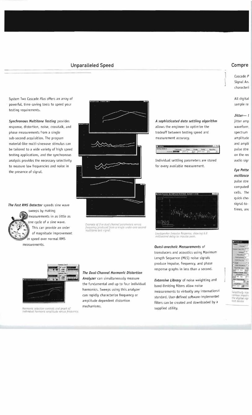