Embed Size (px)
Citation preview

Thursday, November 03, 2016 City of Ottawa 110 Laurier Ave West Ottawa, ON K1P 1J1 Attn: Kimberly Baldwin Re: Site Plan Application – 412 Lisgar Street –Application #D07-12-16-01111 ________________________________________________________________________ Please find enclosed the following in response to City of Ottawa review comments dated September 23rd, 2016: Civil: Enclosed please find (3) copies of the Servicing, Grading and Erosion
Control Plan as prepared by Novatech Engineering – dated October 27th 2016.
Landscape: Enclosed please find (3) copies of the Landscape Plan as prepared by
James B. Lennox and Associates – dated October 31st 2016. Architectural: Enclosed please find (3) copies of the Architectural Plans, Elevations and
Renderings as prepared by Roderick Lahey Architect Inc– dated October 21st 2016.
Should you require additional information please advise. Sincerely, Nina Davidson Project Coordinator

D07-12-16-0111
September 23, 2016 VIA EMAIL to Neil Malhotra, [email protected]; Nina Davidson, [email protected] Dear Mr. Malhotra, Re: 412 Lisgar Street Site Plan Application I have summarized the technical comments that have been provided on the site plan control application. Please review and provide responses to all the comments provided below. When you provide your resubmission, please include a cover letter (3 copies) indicating how the comments have been addressed, accompanied by 3 sets of all revised plans. All addenda or revisions to any studies, or plans, must be accompanied by a *.pdf copy (either by CD or e-mail).
A. GENERAL COMMENTS
1. This development will be subject to parkland dedication as per By-law 2009-95. Click here for more information: http://ottawa.ca/en/residents/laws-licenses-and-permits/laws/parkland-dedication-law-law-no-2009-95
2. Status of Minor Variance Application.
• It is our understanding that the minor variance application (D08-02-15/A-00194) was filed on May 29, 2015 and adjourned sine die.
• As the minor variance application was received and submission deemed complete prior to July 8, 2015, this application falls under the transition clause in Section 9 of the Zoning Bylaw. Please be advised that this transition period will expire on July 8, 2017 (Variances would have to be approved and a building permit for the proposed development must be issued prior to this date).
1

• After July 8, 2017, the new zoning provisions as amended in Bylaw 2015-228 (a.k.a. Infill II regulations) will apply. For simplicity and greater flexibility on the timing of development, consider applying all the new regulations when the variance application is re-activated. For example: the new rear yard setback requirement is 30% of lot depth which must comprise of at least 25% of the area of the lot.
3. Please be advised that the Amenity Area requirements in Section 137 of
the Zoning Bylaw were revised in 2014. For ease of reference, I have copy/pasted an excerpt from the Bylaw below: Amenity area provided as communal in the rear yard is 52.4 m2
Amenity Area (Section 137) 137. (1) Amenity area must be provided for a residential use that is a permitted use in
the zone in which it is located, in accordance with Table 137. (2) Amenity area must be located on the same lot as the use for which it is
provided. (3) Amenity area provided outdoors must not be located in a required front or
corner side yard. (4) Where amenity area is located outside at grade, it may be included in the
calculation of landscaped area requirements. (5) Minimum required communal amenity area may only be included as part of a
required landscaped buffer where it is aggregated into areas of 54m2 or more.
Table 137- Amenity Area (By-law 2014-189) (OMB Order File #PL150797 issued July 25, 2016 – By-law 2015-228)
I
Land Use
II
Total Amenity Area
III
Communal Amenity Area
IV
Layout of Communal Amenity Area
(3) Low-rise Apartment Dwelling in any Residential Zone within the area shown as Area A on Schedule 321
15m2 per dwelling unit up to 8 units, plus 6m2 per unit in excess of 8.
100% of the amenity area required for the first 8 units.
Communal amenity area required for the first 8 units must: -be located at grade and in the
2

rear yard;
-be landscaped; -consist of at least 80% soft landscaping; and -abut the rear lot line, unless the lot has access to a rear lane
(6) Despite rows (1) through (3) of Table 137: (b) the total amenity area required at grade for all Three-unit Dwellings, Low-
rise Apartment Dwellings, Rooming Houses and Converted Rooming Houses in the Planned Unit Development does not need to exceed 120 m2. (By-law 2014-189)
4. Based on our assessment, minor variances are required for lot width, lot
area, rear yard setback, interior side yard setback, amenity area, and possibly front yard setback.
Lot area is 308.5 m2 Rear yard setback is 6.0 metres Interior side yard setback is 1.5 metres for the full length of the lot Amenity area is 52.4 m2 communal, 16.0 m2 private (Total 68.4 m2, 8.55 m2 per unit) Front yard is 3.0 metres
5. Please show on the site plan the 21 metre depth dimension for review of the interior side yard setback. The 21.0 metre dimension has been added to the site plan
6. Please show the front yard setback dimension on abutting properties to confirm compliance or whether a variance is required.
Item 6 We have added a 3.0 m dimension to the vacant lot to the west. 7. As there will be no vehicular parking, the proposed development should
provide good bicycle parking opportunities for the residents of this building. Consider providing a ratio of one bicycle space per unit.
4 bicycle parking spaces shown on the attached landscape plan.
8. Consider providing a bicycle enclosure that is secure and sheltered from weather. Acknowledged
9. Create a waste management area inside the building to allow more room and better enjoyment of the amenity space in the rear yard. The required
3

dimensions for waste management are provided in Waste Services comments below. Acknowledged
10. Is the easement adjacent to 414 Lisgar a right-of-way for vehicular
passage? Refer to the attached Civil Plan.
B. URBAN DESIGN COMMENTS
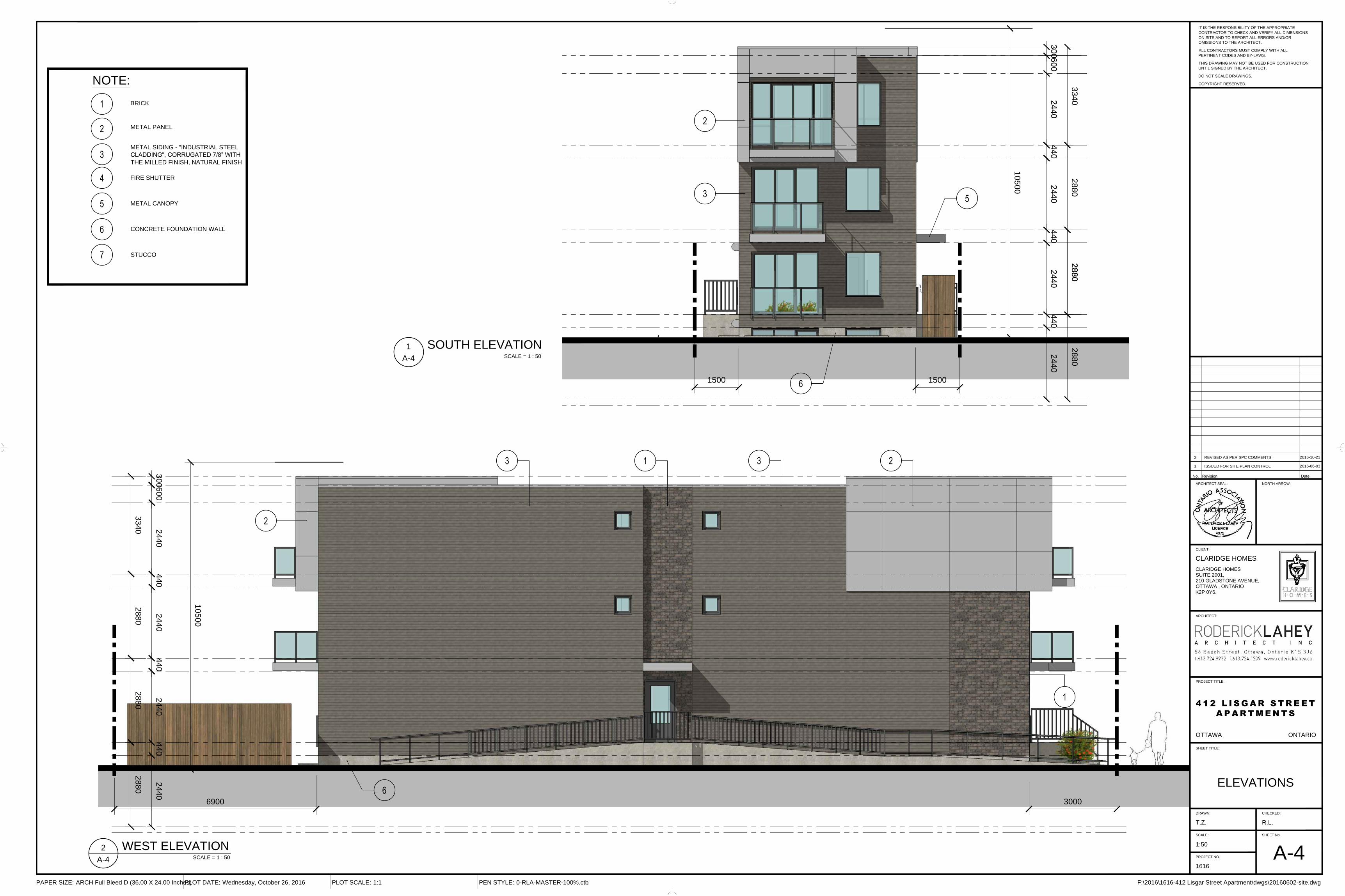
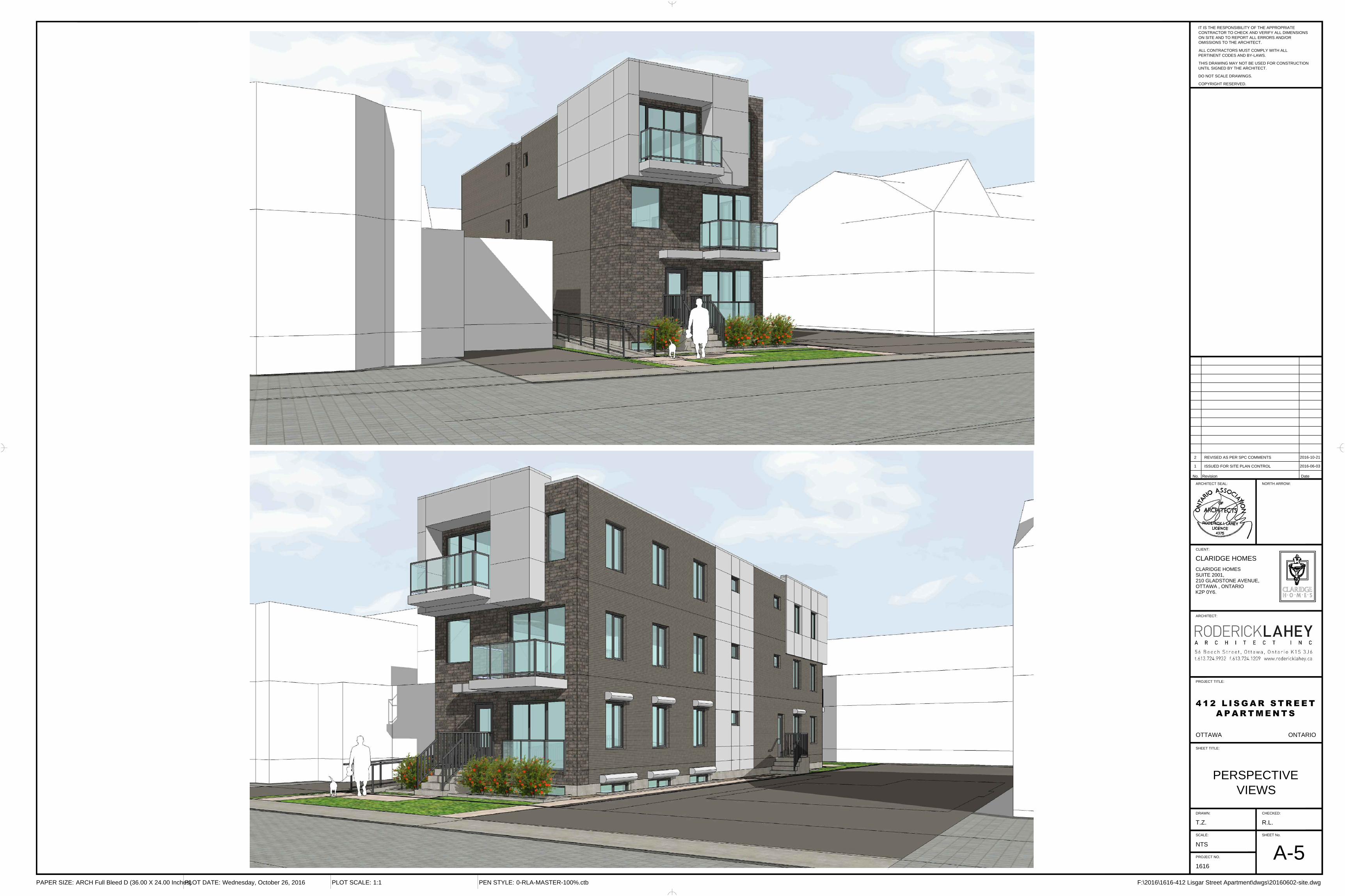
11. Façade articulation: a. It is appreciated that the street façade employs a masonry facing,
however to avoid this looking like a simple appliqué, it is recommended that the masonry be taken around both corners of the façade to the side elevations for at least a part of those building faces.
See revised coloured elevations and added building perspective sheet 12. Material treatment and their relationships on the building:
b. There doesn’t appear to be sufficient information on what is meant by ‘metal siding’ on the facades. Please provide additional detail.
See revised coloured elevations and added building perspective sheet. 13. Architectural elements:
c. The ramp/access to the rear yard is not illustrated on the elevations. The ramp has been added to the east elevation
d. The east and west elevations are both of equal distance from the property lines. Not clear why the west elevation has so few window openings (which would break up the mass of the three+ storey very long wall and provide further articulation). Please explain. We have the maximum windows the building code allows, the majority of the windows are along the west side to maximise the sun and the existing view. The east side looks into the rear yards of the houses along Kent Street and which has a very undesirable view.
14. Building massing: e. The Metal panel box on the front and rear façade is an appreciated
architectural detail to provide visual interest for the building. Acknowledged
4

C. ENGINEERING COMMENTS
15. There is one big issue. The back yard drainage from the Catch Basin is within 1.0 metre of the foundation wall which is no permitted. Please revise.
Refer to the attached Civil Plan.
D. TRANSPORTATION COMMENTS
16. The section of ramp south of the main entrance does not meet the ramping requirements for accessibility: The Ontario Building Code (OBC, 2006 – Section 3.8.3.4 - Ramps): maximum gradient of 1 in 12 (or 8.3%)
Ramps at front are both 6 % with landing approx.. mid way
17. If longitudinal grades are greater than 8% alternative solutions such as the use of handrails should be considered. Refer to comment #16.
18. The closure of an existing private approach shall reinstate the sidewalk, shoulder, curb and boulevard to City standards. Remove the depressed curb and bring it to sidewalk height. Show on all plans. Refer to the attached Civil & Architectural Drawings.
19. For the interlock pavers, landscaped areas and public art on City’s road right-of-way the developer has to sign a “Maintenance Agreement” with the City to cover any claims. Acknowledged
E. WASTE SERVICES COMMENTS
20. Additional details are required about the garbage enclosure. Provide the dimension of the enclosure and door opening. Also, the pathway leading to the street should be a minimum of 2.2 metres.
This is what is required for containers: Garbage: 1 x 2 yard Fibre: 2 x 360L cart Glass metal plastic: 1 x 360L cart Organics: 1 x 240L cart. Refer to the attached Landscape Drawings.
F. FORESTRY COMMENTS 21. Norway Maple is considered an invasive species and Forestry Services
does not plant them nor would approve the planting of this species on the City’s ROW. Please revise and use an alternate species. Refer to the attached Landscape Drawings.
5

22. The location of the 3 Elm Trees on the TCR and the site plan, servicing/grading plans seem to be different. Please revise Refer to the attached Landscape Drawings.
23. Show the critical root zone for the trees on the TCR. Refer to the attached Landscape Drawings.
24. Show the limits of excavation for the catch basin on the TCR. I am concerned that the excavation within the Critical Root Zone will compromise the health/stability of the retained trees. Refer to the attached Landscape Drawings.
FORESTRY COMMENTS
25. Norway Maple is considered an invasive species and Forestry Services does not plant them nor would approve the planting of this species on the City’s ROW. Please revise and use an alternate species. Refer to the attached Landscape Drawings.
26. The location of the 3 Elm Trees on the TCR and the site plan, servicing/grading plans seem to be different. Please revise. Refer to the attached Landscape Drawings.
27. Show the critical root zone for the trees on the TCR. Refer to the attached Landscape Drawings.
28. Show the limits of excavation for the catch basin on the TCR. I am concerned that the excavation within the Critical Root Zone will compromise the health/stability of the retained trees. Refer to the attached Landscape Drawings.
G. BUILDING CODE SERVICES COMMENTS
29. A building permit is required for the construction of the building. Acknowledged
30. Request for a Conditional permit may be considered only after approval is obtained from Development Review Services Urban Inner Core Branch Acknowledged
6

H. EXTERNAL AGENCIES COMMENTS
Hydro Ottawa Please find attached comments.
Enbridge Please find attached comments. Bell Canada
We have reviewed the circulation regarding the above noted application. We have no conditions and/or objections to the application at this time. We hereby advise the Developer, however, to contact Bell Canada during detailed design to confirm the provision of communication/telecommunication infrastructure needed to service the development.
As you may be aware, Bell Canada is Ontario’s principal telecommunications infrastructure provider, developing and maintaining an essential public service. It is incumbent upon the Municipality and the Developer to ensure that the development is serviced with communication/telecommunication infrastructure. In fact, the 2014 Provincial Policy Statement (PPS) requires the development of coordinated, efficient and cost-effective infrastructure, including telecommunications systems (Section 1.6.1).
The Developer is hereby advised that prior to commencing any work, the Developer must confirm that sufficient wire-line communication/telecommunication infrastructure is available. In the event that such infrastructure is unavailable, the Developer shall be required to pay for the connection to and/or extension of the existing communication/telecommunication infrastructure.
If the Developer elects not to pay for the above noted connection, then the Developer will be required to demonstrate to the satisfaction of the Municipality that sufficient alternative communication/telecommunication will be provided to enable, at a minimum, the effective delivery of communication/telecommunication services for emergency management services (i.e., 911 Emergency Services).
MMM (a WSP company) operates Bell Canada’s development tracking system, which includes the intake and processing of municipal circulations. Please note, however, that all responses to circulations and other requests, such as requests for clearance, come directly from Bell Canada, and not from MMM. MMM is not responsible for the provision of comments or other responses.
7

Should you have any questions, please contact the undersigned. Meaghan Palynchuk Manager, Municipal Relations Access Network Provisioning, Ontario Phone: 905-540-7254 Mobile: 289-527-3953 Email: [email protected]
Rideau Valley Conservation Authority
This application indicates that the stormwater run off from this development will directed to an existing municipal sewer on Lisgar Street which ultimately outlets into the Ottawa River. No municipal treatment for quality is provided. However, based on the plans provided, this redevelopment will be primarily rooftop area receiving rainwater. Roofs and landscaped areas, for our purposes, are deemed as clean. The RVCA therefore accepts that the stormwater runoff from the site does not require any additional quality control measures for protection of the Ottawa River water quality. We will rely on the City of Ottawa to ensure that the storm water site management plan is consistent with the quantity design assumptions for the receiving storm sewer.
Rogers Communications Partnership
Rogers Communications Partnership has no concerns or objection in regards to the attached circulation. Please contact Martin Proulx at 613-688-2191 or e-mail at [email protected] for Rogers Site Servicing if approved.
Other Agencies
The following agencies provided comments but have no objections to the application:
i. Group Telecom ii. Telus iii. Conseil des écoles publiques de l”Est de l’Ontario iv. Conseil des écoles catholiques du centre-est v. Zayo
I. COUNCILLOR’S COMMENTS
Councillor McKenney’s office has not provided any comments at this time.
8
J. PUBLIC COMMENTS
We received one comment from a representative of the Centretown Citizens Community Association (CCCA). Their comments are stated as follows: It is impossible to make a recommendation to our Board of Directors on a site plan application that does not conform to the zoning by-law on the assumption that the minor variance will be approved. The CCCA Board voted to oppose the minor variance application in July 2015. It can be presumed from our previous opposition to the minor variance that we also would oppose a site plan based on variances that we previously opposed.
If you have any comments or questions about the summary of comments, please contact the undersigned at [email protected] or 613-580-2424 x 23032. Sincerely, l Signed by Kimberley Baldwin”
Kimberley Baldwin Planner, Inner Core, Urban Services Branch Urbaniste - Noyau Interne, Services Urbain City of Ottawa | Ville d'Ottawa cc: John Wu, Infrastructure Approvals Manager
9

EX
IT
MA
IN E
NTR
AN
CE
SLO
PE
6.0%S
LOP
E 6.0%
EX
ISTIN
G 2 S
TOR
EY
RE
SID
EN
CE
EX
ISTIN
G 2 12 S
TOR
EY
RE
SID
EN
CE
EX
ISTIN
G 2 12 S
TOR
EY
RE
SID
EN
CE
EX
ISTIN
G 2
STO
RE
YR
ES
IDE
NC
E
EXISTING 3 STOREY TOWNHOUSEDEVELOPMENT
1:12 SLO
PE
CONC. SIDE WALK
Frame
Porch
No. 2562 Storey
Dwelling
No. 2581 Storey Vinyl Sided
Addition
No. 2621 Storey Stucco Sided
AdditionFram
eShed
N 58° 58' 40" E9.02
N 59°01'40" E9.02
N 31°08'50" W34.24
N 31°08'50" W34.24
1 Storey
DC
Brick
Brick
412 LISGAR STREETPROPOSED 3 STOREYAPARTMENT BUILDING
(8 UNITS)
PROPOSED PANEL FENCE
PROPOSED PANEL FENCE
PROPOSED PANEL FENCE
STM SA
NW
ATE
R
SAN INV=69.12±
200mm STM INV=70.66±
CONNECTION TO SANITARY AND STORMTO BE MADE AT 2 O'CLOCK USING COREAND SADDLE METHOD.
13.10m-150mm SAN SERVICE @1.0%. INV @ BLDG=70.0014.30m-200mm STM SERVICE @ 1.0%. INV @ BLDG=70.80
REFER TO GRADING NOTES 8
INV.=71.80
CONNECTION TO EXISTING WATERMAINBY CITY FORCES. CONTRACTOR TOPROVIDE EXCAVATION, BACKFILLAND REINSTATEMENT.T/WM=± 70.66
T/G=73.00CB
FF=74.08TF=73.64
USF=71.00
SP
HYDROMETER
GASMETER
0+00.00
0+03.25
0+08.10
0+11.15
PROTECT EXISTING POLEDURING CONSTRUCTION
SW
ALE
SERVICES @ BLDG FACE:11.50m-100mm WATER SERVICE
NOTE:MAKE SEWER CONNECTIONS@ STREET AND RUN PIPE TOFACE OF FOUNDATION BEFOREESTABLISHING FOOTING ELEVATION.INSTALL BACKWATER VALVES AS PERCITY OF OTTAWA S14
PROPOSED ROAD CUT AND ASPHALTREINSTATEMENT AS PER R10. CONTRACTORTO EXPOSE EXISTING SERVICES AND ADVISE
ENGINEER OF ELEVATIONS AND LOCATIONPRIOR TO PROCEEDING FURTHER.
WIN
DO
W W
ELL
WINDOW WELL
WINDOW WELL
RAMP WALL AND RAILSEE ARCHITECTURALAND STRUCTURAL
43.8m - 200mmØ SDR35CB LEAD @ 1.0%
42.8m - 200mmØ SDR35CB LEAD @ 1.0%
4R @ 180mm
3R @ 180mmWATER METERUNDER BASEMENTSTAIRS
100m
m D
R18
WA
TER
MA
IN U
ND
ER
SLA
B
1.1m
EX
IT
MA
IN E
NTR
AN
CE
SLO
PE
6.0%S
LOP
E 6.0%
EX
ISTIN
G 2 S
TOR
EY
RE
SID
EN
CE
EX
ISTIN
G 2 12 S
TOR
EY
RE
SID
EN
CE
EX
ISTIN
G 2 12 S
TOR
EY
RE
SID
EN
CE
EX
ISTIN
G 2
STO
RE
YR
ES
IDE
NC
E
EXISTING 3 STOREY TOWNHOUSEDEVELOPMENT
1:12 SLO
PE
CONC. SIDE WALK
Frame
Porch
No. 2562 Storey
Dwelling
No. 2581 Storey Vinyl Sided
Addition
No. 2621 Storey Stucco Sided
AdditionFram
eShed
N 58° 58' 40" E9.02
N 59°01'40" E9.02
N 31°08'50" W34.24
N 31°08'50" W34.24
1 Storey
DC
Brick
Brick
412 LISGAR STREETPROPOSED 3 STOREYAPARTMENT BUILDING
(8 UNITS)
PROPOSED PANEL FENCE
PROPOSED PANEL FENCE
PROPOSED PANEL FENCE
73.28
73.01
4.0%
2.0%
REFER TO GRADING NOTES 8
T/G=73.00CB
FF=74.08TF=73.64
USF=71.00
73.17
73.20
73.08
73.24
73.30
(PL)
73.4
1(PL
)
73.30(PL)
73.34
SP
PROTECT EXISTING POLEDURING CONSTRUCTION
73.3
0(PL
) 73.32
(PL)
73.24
73.33
3.0%
74.05
74.05
SW
ALE
74.0
5
73.34
73.4573.40(PL)
1.25%1.25%
2.0%
73.35(S)
73.45
73.6
4
74.05
73.5
1
73.15
73.30(PL)
73.15 PROPOSED (TYP)
73.20
73.25
EROSION AND SEDIMENTCONTROL FENCE TO BEINSTALLED ON ADJACENT ANDREAR PROPERTY LINES ANDIS TO BE MAINTAINED UNTILCONSTRUCTION IS COMPLETED
EROSION AND SEDIMENTCONTROL FENCE TO BE
INSTALLED ON ADJACENT ANDREAR PROPERTY LINES ANDIS TO BE MAINTAINED UNTIL
CONSTRUCTION IS COMPLETED
PROPOSED ROAD CUT AND ASPHALTREINSTATEMENT AS PER R10. CONTRACTORTO EXPOSE EXISTING SERVICES AND ADVISE
ENGINEER OF ELEVATIONS AND LOCATIONPRIOR TO PROCEEDING FURTHER.
73.20(S)
73.2
5(PL
)
73.6
6
RAMP WALL AND RAILSEE ARCHITECTURALAND STRUCTURAL
73.24
73.14
4R @ 180mm
T/WW=73.50
T/WW=73.50
T/WW=73.50
3R @ 180mm
74.05
74.0
5
73.05
73.1
4
73.30
M:\2
010\
1100
50\C
AD
\Des
ign\
1100
50-G
S.d
wg,
GS
, Oct
27,
201
6 - 1
0:13
am, m
linto
n
PLANA1.DWG - 841mmx594mm
NOTE:THE POSITION OF ALL POLE LINES, CONDUITS,WATERMAINS, SEWERS AND OTHERUNDERGROUND AND OVERGROUND UTILITIES ANDSTRUCTURES IS NOT NECESSARILY SHOWN ONTHE CONTRACT DRAWINGS, AND WHERE SHOWN,THE ACCURACY OF THE POSITION OF SUCHUTILITIES AND STRUCTURES IS NOT GUARANTEED.BEFORE STARTING WORK, DETERMINE THE EXACTLOCATION OF ALL SUCH UTILITIES ANDSTRUCTURES AND ASSUME ALL LIABILITY FORDAMAGE TO THEM.
PROJECT No.
REV
DRAWING No.
DRAWING NAME
LOCATION
No. REVISION DATE BY
FOR REVIEW ONLYSCALE
APPROVED
CHECKED
DRAWN
CHECKED
DESIGN
N.T.S.NORTH KEY PLAN
1 ISSUED FOR CLIENT REVIEW MAR 01/10 BHB
110050-00
REV # 03
110050-GS
GJM
GJM
MWC
GJM
GJM
SERVICING, GRADING ANDEROSION CONTROL PLAN
CITY OF OTTAWA412 LISGAR STREET
CLARIDGE HOMESCLARIDGE HOMESSUITE 2001,210 GLADSTONE AVENUE,OTTAWA , ONTARIOK2P 0Y6.
CO
NS
TRU
CTI
ON
NO
RTH
N SITE
GEODETIC BENCHMARKNCC MON 310 3° TRANSVERSN: 5,030,878.00E: 367,376.00ELEV. 73.873
COOPER ST
GLOUCESTER ST
JAMES ST
KENT STLAURIER AV
LISGAR ST
LYON ST N
NEPEAN ST
SLATER ST
SOMERSET ST
BRO
NSO
N AV
CAMBRIDG
E ST N
QUEEN ST
BAY ST
PERCY ST
GILMOUR ST
MACLAREN ST
LISGAR STREET
SERVICING DRAWING GRADING DRAWING
LISGAR STREET
UNDERSIDE OFFOOTING ELEVATION
TOP OF FOOTING ELEVATION
PROPOSED ELEVATION
DRAINAGE EASEMENT LIMIT
C SWALE AND DIRECTION OF FLOW
PROPOSED SWALE ELEVATION
PROPOSED PROPERTY LINE ELEVATION
USF=
T/F=
L
73.25
73.10(S)
73.30(PL)
PROPOSED DOORWAY ELEVATION74.45
REARYARD GRADE AND DIRECTION
MAXIMUM 3: 1 SIDESLOPE
DRIVEWAY GRADE AND DIRECTION3.2%
PROPOSED TOP OF BOTTOM FLANGE
PROPOSED HYDRANT LOCATIONHYD
T/F=127.55
PROPOSED SILT FENCE
PROPOSED STORM SEWER
PROPOSED BARRIER CURB
PROPOSED DEPRESSED CURB
DIRECTION OF FLOW
PROPOSED VALVE & VALVE BOX
PROPOSED SANITARY MANHOLE
PROPOSED STORM MANHOLE
PROPOSED CATCHBASIN
PROPOSED CATCHBASIN/MANHOLE
PROPOSED CONCRETE SIDEWALK
PROPOSED CABLE PEDESTAL
PROPOSED BELL PEDESTAL
PROPOSED GAS METER
FH
WV
VC
H
T
TRAFF LT
LS
GM
IRON BAR & PROPERTY LINE
LEGAL ADJACENT
TMH
UP
PROPOSED SANITAY SEWER
X
REMOVALXX
ADJUSTED
PROPOSED REMOTE RECEPTACLE
PROPOSED WATER METER
PROPOSED STAND POST
2) INSULATE ALL PIPES (SAN/STM) THAT HAVE LESS THAN 1.5m COVER WITH50mmX1200mm HI-40 INSULATION. PROVIDE 150mm CLEARANCE BETWEEN PIPE ANDINSULATION.
3) SERVICES ARE TO BE CONSTRUCTED TO 1.0m FROM FACE OF BUILDING AT A MINIMUMSLOPE OF 1.0%.
4) PIPE BEDDING, COVER AND BACKFILL ARE TO BE COMPACTED TO AT LEAST 95% OFTHE STANDARD PROCTOR MAXIMUM DRY DENSITY. THE USE OF CLEAR CRUSHEDSTONE AS A BEDDING LAYER SHALL NOT BE PERMITTED.
5) FLEXIBLE CONNECTIONS ARE REQUIRED FOR CONNECTING PIPES TO MANHOLES(FOR EXAMPLE KOR-N-SEAL, PSX: POSITIVE SEAL AND DURASEAL). THE CONCRETECRADLE FOR THE PIPE CAN BE ELIMINATED.
6) THE OWNER SHALL REQUIRE THAT THE SITE SERVICING CONTRACTOR PERFORMFIELD TESTS FOR QUALITY CONTROL OF ALL SANITARY SEWERS. LEAKAGE TESTINGSHALL BE COMPLETED IN ACCORDANCE WITH OPSS 410.07.16, 410.07.16.04 AND407.07.24. DYE TESTING IS TO BE COMPLETED ON ALL SANITARY SERVICES TOCONFIRM PROPER CONNECTION TO THE SANITARY SEWER MAIN. THE FIELD TESTSSHALL BE PERFORMED IN THE PRESENCE OF A CERTIFIED PROFESSIONAL ENGINEERWHO SHALL SUBMIT A CERTIFIED COPY OF THE TEST RESULTS.
SEWER NOTES:
WITH MAXIMUM PARTICLE SIZE=25mm)
CATCHBASIN (600x600mm)
COVER (GRANULAR A OR GRANULAR B TYPE I,BEDDING (GRANULAR A)
SANITARY SERVICE
SEWER TRENCH -CB FRAME & COVER
1) SPECIFICATIONS:ITEM
PVC DR 28
OPSDOPSD
705.010400.020
SPEC. No.OPSDOPSD
REFERENCE
GENERAL NOTES:1) COORDINATE AND SCHEDULE ALL WORK WITH OTHER TRADES AND CONTRACTORS.
2) DETERMINE THE EXACT LOCATION, SIZE, MATERIAL AND ELEVATION OF ALL EXISTINGUTILITIES PRIOR TO COMMENCING CONSTRUCTION. PROTECT AND ASSUMERESPONSIBILITY FOR ALL EXISTING UTILITIES WHETHER OR NOT SHOWN ON THISDRAWING.
3) OBTAIN ALL NECESSARY PERMITS AND APPROVALS FROM THE CITY OF OTTAWABEFORE COMMENCING CONSTRUCTION.
4) BEFORE COMMENCING CONSTRUCTION OBTAIN AND PROVIDE PROOF OFCOMPREHENSIVE, ALL RISK AND OPERATIONAL LIABILITY INSURANCE FOR$2,000,000.00. INSURANCE POLICY TO NAME OWNERS, ENGINEERS AND ARCHITECTSAS CO-INSURED.
5) RESTORE ALL DISTURBED AREAS ON-SITE AND OFF-SITE, INCLUDING TRENCHES ANDSURFACES ON PUBLIC ROAD ALLOWANCES TO EXISTING CONDITIONS OR BETTER TOTHE SATISFACTION OF THE CITY OF OTTAWA AND ENGINEER.
6) REMOVE FROM SITE ALL EXCESS EXCAVATED MATERIAL, ORGANIC MATERIAL ANDDEBRIS UNLESS OTHERWISE INSTRUCTED BY ENGINEER. EXCAVATE AND REMOVEFROM SITE ANY CONTAMINATED MATERIAL. ALL CONTAMINATED MATERIAL SHALL BEDISPOSED OF AT A LICENSED LANDFILL FACILITY.
7) ALL ELEVATIONS ARE GEODETIC.
8) REFER TO ARCHITECT'S AND LANDSCAPE ARCHITECT'S DRAWINGS FOR BUILDING ANDHARDSURFACE AREAS AND DIMENSIONS.
9) SAW CUT AND KEY GRIND ASPHALT AT ALL ROAD CUTS AND ASPHALT TIE IN POINTS ASPER CITY OF OTTAWA STANDARDS (R10).
10) CONTRACTOR TO PROVIDE THE CONSULTANT WITH A GENERAL PLAN OF SERVICESINDICATING ALL SERVICING AS-BUILT INFORMATION SHOWN ON THIS PLAN. AS-BUILTINFORMATION MUST INCLUDE: PIPE MATERIAL, SIZES, LENGTHS, SLOPES, INVERT ANDT/G ELEVATIONS, STRUCTURE LOCATIONS, VALVE AND HYDRANT LOCATIONS, T/WMELEVATIONS AND ANY ALIGNMENT CHANGES, ETC.
PVC CLASS 150 DR18
W17SPEC. No.
WATERMAIN SERVICE
WATERMAIN TRENCHING ITEM
1) SPECIFICATIONS:
WATERMAIN NOTES:
CITY OF OTTAWAREFERENCE
W50 WATERMAIN SERVICE CITY OF OTTAWAW22 THERMAL INSULATION IN SHALLOW TRENCHES CITY OF OTTAWA
2) SUPPLY AND CONSTRUCT ALL WATERMAINS AND APPURTENANCES IN ACCORDANCEWITH THE CITY OF OTTAWA STANDARD AND SPECIFICATIONS. EXCAVATION,INSTALLATION, BACKFILL AND RESTORATION OF ALL WATERMAINS BY THECONTRACTOR. CONNECTIONS AND SHUT-OFFS AT THE MAIN AND CHLORINATION OFTHE WATER SYSTEM SHALL BE PERFORMED BY CITY OFFICIALS.
3) WATERMAIN SERVCE SHALL BE MINIMUM 2.4m DEPTH BELOW GRADE UNLESSOTHERWISE INDICATED.
4) PROVIDE MINIMUM 0.25m CLEARANCE BETWEEN OUTSIDE OF PIPES AT ALLCROSSINGS.
5) WATER SERVICE IS TO BE CONSTRUCTED TO WITHIN 1.0m OF FOUNDATION WALL ANDCAPPED, UNLESS OTHERWISE INDICATED.
6) AVERAGE WATER DEMAND = 4,900 L/day
STORM SERVICE PVC DR 28CB LEAD PVC SDR 35
PAVEMENT STRUCTURE:
WALKWAY:
BRICK150mm GRAN "A"
WATERMAIN TABLE: LISGAR CONNECTION(MIN COVER = 2.4m)
STATION GRADE T/WM DESCRIPTION0+00.00
0+03.250+08.10
73.06 70.66 * CONNECTION TO MAINCURB FACESTANDPOST (P)
0+11.15 BLDG FACE
73.03 70.6373.25 70.8373.34 70.94
GRADING NOTES:
1) ALL TOPSOIL, ORGANIC OR DELETERIOUS MATERIAL MUST BE ENTIRELY REMOVED FROM BENEATH THEPROPOSED PAVED AREAS.
2) EXPOSED SUBGRADES IN PROPOSED PAVED AREAS SHOULD BE PROOF ROLLED WITH A LARGE STEELDRUM ROLLER AND INSPECTED BY THE GEOTECHNICAL CONSULTANT.
3) ANY SOFT AREAS EVIDENT FROM THE PROOF ROLLING SHOULD BE SUBEXCAVATED AND REPLACED WITHSUITABLE MATERIAL THAT IS FROST COMPATIBLE WITH THE EXISTING SOILS.
4) THE GRANULAR BASE SHOULD BE COMPACTED TO AT LEAST 100% OF THE STANDARD PROCTORMAXIMUM DRY DENSITY VALUE. ANY ADDITIONAL GRANULAR FILL USED BELOW THE PROPOSEDPAVEMENT SHOULD BE COMPACTED TO AT LEAST 95% OF THE STANDARD PROCTOR MAXIMUM DRYDENSITY VALUE.
5) GRADE AND/OR FILL BEHIND PROPOSED CURB AND BETWEEN BUILDINGS AND CURBS, WHERE REQUIREDTO PROVIDE POSITIVE DRAINAGE.
6) MINIMUM OF 2% GRADE FOR ALL GRASS AREAS UNLESS OTHERWISE NOTED.
7) ALL GRADES BY CURBS ARE EDGE OF PAVEMENT GRADES UNLESS OTHERWISE INDICATED.
8) REINSTATE 1.5m WIDE MONOLITHIC SIDEWALK AND CURB ALONG THE FRONTAGE OF THE PROPERTY ASPER CITY OF OTTAWA SC2
9) REFER TO LANDSCAPE PLAN FOR PLANTING AND OTHER LANDSCAPE FEATURE DETAILS.
EROSION AND SEDIMENT CONTROL NOTES:
1) THE OWNER AGREES TO PREPARE AND IMPLEMENT AN EROSION AND SEDIMENTCONTROL PLAN TO THE SATISFACTION OF THE CITY OF OTTAWA, APPROPRIATE TOTHE SITE CONDITIONS, PRIOR TO UNDERTAKING ANY SITE ALTERATIONS (FILLING,GRADING, REMOVAL OF VEGETATION, ETC.) AND DURING ALL PHASES OF SITEPREPARATION AND CONSTRUCTION IN ACCORDANCE WITH THE CURRENT BESTMANAGEMENT PRACTICES FOR EROSION AND SEDIMENT CONTROL SUCH AS BUT NOTLIMITED TO INSTALLING FILTER CLOTHS ACROSS MANHOLE/CATCHBASIN LIDS TOPREVENT SEDIMENTS FROM ENTERING STRUCTURES AND INSTALL AND MAINTAIN ALIGHT DUTY SILT FENCE BARRIER AS REQUIRED.
2) THE CONTRACTOR SHALL PLACE FILTER CLOTH UNDER THE CATCHBASIN ANDMANHOLE GRATES FOR THE DURATION OF CONSTRUCTION AND WILL REMAIN INPLACE DURING ALL PHASES OF CONSTRUCTION.
3) SILT FENCING FOR ENTIRE PERIMETER OF SITE, SHALL BE UTILIZED TO CONTROLEROSION FROM THE SITE DURING CONSTRUCTION.
4) THE CONTRACTOR ACKNOWLEDGES THAT FAILURE TO IMPLEMENT EROSION ANDSEDIMENT CONTROL MEASURES MAY BE SUBJECT TO PENALTIES IMPOSED BY ANYAPPLICABLE REGULATORY AGENCY.
GEOTECHNICAL REFERENCE:
REFER TO GEOTECHNICAL REPORT BY PATTERSON GROUP. REPORT No. PG 3838-LET-01. JUNE 21, 2016.
PROPOSED WATERMAIN SERVICE
1:150
601:150
42
CB ID
CB 1
T/GRATE INVERT
73.00 71.80
CATCHBASIN TABLE
PROPOSED DOOR LOCATION L
SIZE
600 x 600
2 ISSUED FOR SITE PLAN APPLICATION MAR 12/10 GJM
W32 WATER METER CITY OF OTTAWA
MINIMUM UNDERSIDE OFFOOTING ELEVATION
MUSF=
3 REISSUED FOR SITE PLAN APPLICATION JUN 07/16 GJM
Engineers, Planners & Landscape Architects
Suite 200, 240 Michael Cowpland Drive
Ottawa, Ontario, Canada K2M 1P6
Telephone (613) 254-9643
Facsimile (613) 254-5867
Website www.novatech-eng.com
NOTE:
CONTRACTOR TO EXTEND SERVICES TO 1.0m FROMFOUNDATION WALL AND CONFIRM ELEVATIONS WITHENGINEER BEFORE POURING FOOTINGS.
PROPOSED TOP OF WINDOW WELLT/WW=73.50
PROPOSED GAS
PROPOSED HYDRO/BELL CABLE
4 REVISED PER CITY COMMENTS OCT 27/16 GJM

EXIT
MAIN ENTRANCE
SLOPE 6.0%
SLOPE 6.0%1:12 SLOPE
CO
NC
. S
ID
E W
AL
K
DC
412 LISGAR STREET
PROPOSED 3 STOREY
APARTMENT BUILDING
(8 UNITS)
SID
EW
AL
K
1
UL
510mm DIA.
GOOD
BIKE PARKING
BA
LC
ON
Y
AB
OV
E
BA
LC
ON
Y
AB
OV
E
OUTDOOR
AMENITY AREA
2.4M HT. OPAQUE SCREENED IN
SOLID WASTE COLLECTION AREA
LIS
GA
R S
TR
EE
T
4
CS
1
AN
390mm DIA.
POOR
15
0
45
0
TOPSOIL MIXTURE AS PER
SPECIFICATIONS.
PLANTING BED AROUND
SHRUBS. COVER ENTIRE BED
WITH 75mm DEPTH
WOODCHIP MULCH. PULL
BACK MULCH FROM BASE OF
SHRUBS. ENSURE THAT
MULCH COVERS ALL
EXPOSED SOIL.
TAPER TO BLEND NATURALLY
WITH FINISHED GRADE.
REMOVE DAMAGED OR
OBJECTIONABLE BRANCHES.
FOLLOW PROPER
HORTICULTURAL PRACTICE.
REMOVE POTS COMPLETELY
FROM POTTED STOCK OR CUT
AND REMOVE BURLAP AND
WIRE FROM TOP 1/3 OF
ROOTBALL.
1500
NOTE
ALL DIMENSIONS ARE IN
MILLIMETRES. USE TREE
SPECIES TOLERANT TO
POORLY DRAINED SOIL
CONDITIONS
3
1
PLACE 1/3 OF ROOT BALL ABOVE GRADE. CUT AND
REMOVE BURLAP AND WIRE BASKET FROM TOP 1/3 OF
ROOTBALL WITHOUT DISTURBING ROOTS.
CONSTRUCT 100mm SAUCER AROUND TREE BASE. FILL WITH
75mm WOODCHIP MULCH. PULL BACK MULCH FROM BASE OF
TREE. ENSURE THAT MULCH COVERS ALL EXPOSED SOIL.
TREE WRAP APPLIED SPIRALLY FROM GROUND UP TO
HEIGHT OF SECOND BRANCHES.
REMOVE DAMAGED OR OBJECTIONABLE BRANCHES.
FOLLOW PROPER HORTICULTURAL PRACTICE. DO NOT
PRUNE LEADER
2 STAKES MIN 2400mm LONG WITH NO. 12 GALVANIZED WIRE
ENCASED IN 12mm DIAMETER RUBBER HOSE ALLOWING SLACK
IN GALVANIZED WIRE. REMOVE STAKES AFTER ONE YEAR.
STAKE BEYOND EDGE OF ROOTBALL.
ROOT COLLAR TO BE
SET 100mm ABOVE
FINISHED GRADE.
TAPER TO BLEND NATURALLY WITH FINISHED GRADE
TOPSOIL MIXTURE AS PER SPECIFICATIONS
COMPACTED
ROOTBALL
SUPPORT PAD
2300
ROOTBALL
3m0 21
SCALE
START DATE
PROJECT NO.
DRAWING NO.
PROJECT NORTH
STAMP
AS SHOWN
PROJECT
MAY 2010
PLOT SIZE ARCH-D
412 LISGAR STREET APARTMENTS
TREE CONSERVATION REPORT
AND
LANDSCAPE PLAN
L.1
ARCHITECTS:
CIVIL ENGINEERS:
CLIENT:
CONSULTANTS
LOCATION PLAN
JAMES B. LENNOX & ASSOCIATES INC.LANDSCAPE ARCHITECTS3332 CARLING AVE. OTTAWA, ONTARIO K2H 5A8Tel. (613) 722-5168 Fax. 1(866) 343-3942
LEGEND
10-CLG-1044
DRAWING
No. Issue
Date
ISSUED FOR COMMENT AND REVIEW1
DD/MM/YYYY
JL
DR CK
1. It is the responsibility of the appropriate contractor or official to report any
errors, omissions or discrepancies on this plan with actual site conditions to
the Landscape Architect before proceeding with construction.
2. The contractor is to notify all utility companies and authorities prior to any
excavation and ascertain locations of underground services.
3. The contractor is to reinstate all areas and items damaged as a result of
construction activity.
4. The contractor is to comply with all pertinent codes and by-laws.
5. The contractor is to maintain a positive surface run-off throughout the entire
construction period.
6. The Landscape Architect is not responsible for subsurface conditions.
7. The contractor is to identify all existing trees to remain on site with the
Landscape Architect prior to construction.
8. The contractor is to stake the proposed location of all plant material in
conjunction with the Landscape Architect prior to excavation.
9. Minimum distances for selected deciduous trees are as follows:
- Sidewalks 1.5m
- Public Streets 2.5m
- Underground Infrastructure 2.0m
10. All trees within 1m of underground utility trenches are to be excavated by
hand.
11. Remove all protective wrapping from tree trunks after installation.
12. Staking of trees shall only be performed if necessary.
13. Ensure that mulch is pulled back a min. distance of 75mm from base of
tree trunk.
GENERAL NOTES:
PROPOSED PLANT LIST
KEY QTY. BOTANICAL NAME COMMON NAME SIZE CONDITION REMARKS
TREES
AP 1 Acer platanoides 'Columnare' Columnare Norway Maple 60mm ø B&B
SHRUBS
RA 23 Ribes alpinum Alpine Currant 600mm ht. Potted 800 mm o.c.
TL 8 Thuja Occidentalis 'Little Teddy' Little Teddy Dwarf Cedar 400 mm spr. Potted 500 mm o.c.
RT 5 Rhus typhina Staghorn Sumac 800 mm ht. Potted 1200 mm o.c.
SP 5 Spiraea x vanhouttei Bridal Wreath Spirea 600 mm ht. Potted 1500 mm o.c.
AH 4 Hydrangea arborescens 'Annabelle' Annabelle Hydrangea 3 gal. pot Potted 800 mm o.c.
JA 39 Juniperus horizontalis 'Andorra Compacta'Compact Andorra Juniper 600mm spr. Potted 800 mm o.c.
VINES
CS 12 Celastrus scandens American Bittersweet 1200mm ht. Potted train up fence
PERENNIALS.
CG 4 Calamagrostis 'Karl Forester' Karl Forester Grass 250mm pot Potted 800 mm o.c.
GROUNDCOVERS
VM 80 Vinca minor Periwinkle 60mm plug Cell Pack 300 mm o.c.
1L.1
TREE CONSERVATION REPORT & LANDSCAPE PLANSCALE 1:75
EXISTING TREES TO REMAIN
(Approximate Location)
EXISTING TREES TO BE REMOVED
(Approximate Location)
PROPOSED TREE
EXISTING WOOD SCREEN FENCE
PROPOSED BLACK VINYL CHAIN LINK
FENCE
4' height with black post and rails.
PROPOSED SHRUBS, VINES,
PERENNIALS
PROPOSED PAVERS
PROPOSED GROUNDCOVERS
PROPOSED PEASTONE
240 Michael Cowpland Dr., Suite 200
Ottawa, ON
Tel : (613) 234.9643
Novatech Engineering Consultants Ltd.
56 Beech St.
Ottawa, ON
Tel : (613) 721.9932
Roderick Lahey Architect Inc.
2L.1
DECIDUOUS TREE PLANTINGN.T.S.
3L.1
SHRUB AND PERENNIAL PLANTINGN.T.S.
SITE
L
I
S
G
A
R
S
T
.
K
E
N
T
S
T
.
VP03/06/2016
2001 Gladstone Ave., Suite 210
Ottawa, ON
Tel : (613) 233.6030
Claridge Homes
ISSUED FOR SITE PLAN CONTROL2 JLVP20/06/2016
KEY
QTY.
SIZE diameter of trunk at breast height (DBH)
Extent of critical root zone (CRZ)
REVISED PER CITY COMMENTS3 JLLC31/10/2016
SIZE diameter of trunk at breast height (DBH)
Extent of critical root zone (CRZ)
EXISTING TREE LIST
KEY QTY. BOTANICAL NAME COMMON NAME SIZE CONDITION REMARKS
TREES
AN 1 Acer negundo Manitoba Maple 390mm DIA. POOR To be removed
AS 2 Acer saccharinum Silver Maple 380-420mm DIA. GOOD To Remain
JN 1 Juglans nigra Black Walnut 550mm DIA. GOOD To Remain
UL 2 Ulmus sp. Elm 510-640mm DIA. GOOD To Remain
QTY.
KEY
SIZE

11
01
40
1
EXIT
MAIN
ENTRANCE
SITE AREA 3318 SQ.FT
3.0 FRONT
YARD SETBACK
7.5 REAR
YARD SETBACK
FIBER
BIN
FIBER
BIN
GLASS
METAL
PLASTIC
SLOPE 1:12 (MAX.)
SLOPE 1:12 (MAX.)
3.0m
24270
6.0m
412 LISGAR STREET
PROPOSED 3 STOREY APARTMENT BUILDING
(8 UNITS)
60
06
1.5
m1
.5
m
15
5
6
5
7
8
9
3
SCALE = 1:75
7.5
0m
2.5 5
10
STM
SAN
WATER
EXISTING 2 STOREY
RESIDENCE
EXISTING 2
1
2
STOREY
RESIDENCE
EXISTING 2
1
2
STOREY
RESIDENCE
EXISTING 2 STOREY
RESIDENCE
EXISTING 3 STOREY
TOWNHOUSE
DEVELOPMENT
SLOPE DOWN 1:12 (MAX.)
11
00
3
No. 414
Frame
Porch
No. 256
2 Storey Brick
Dwelling
No. 258
1 Storey Vinyl Sided
Addition
No. 262
1 Storey Stucco Sided
Addition
Frame
Shed
N 58° 58' 40" E
9.0
2
N 59°01'40" E
9.0
2
N 31°08'50" W 34.24
N 31°08'50" W 34.24
SUBJECT TO EASEMENT INST. CR530616
1.0
71
.3
7
18.90
1 Storey Brick
323
3
10
10
3
61
7
8
11
11
11
12
12 13
13
14
3
15
18
17
16
19
1.5M INTERIOR SIDE YARD
SETBACK LESS THAN 11.0 M
17
17
6000 1670 6543 1666 9000
20
±15 METRES TO FIRE HYDRANT
JOB BENCHMARK
Top of Spindle on
Fire Hydrant
Elev=73.93
(AT CORNER)
3000
6.0M SIDE
YARD SETBACK
AFTER 21.0m
1.5M INTERIOR SIDE YARD
SETBACK LESS THAN 11.0 M
21
1800
TYP.
5606
1163
ORG.
19
21.0m
ZONING
308.5 sq. m.
(3,321 sq. ft.)
SITE AREA
PROJECT INFORMATION
SITE PLAN DRAWING NOTE:
Zoning By-Law 2008-250 R4T(479)
BUILDING STATISTICS
SETBACKS
FRONT YARD 3.0 m.
INTERIOR SIDE YARD
1.5 m.
REAR YARD 7.5 m.
BUILDING HEIGHT 14.5 m.
LOT WIDTH (MINIMUM) 15.0 m.
LOT AREA (MINIMUM) 450.0 sq. m.
145.4 sq. m.BUILDING FOOTPRINT
9.02 m.
LOT WIDTH
52.9%LANDSCAPE AREA 163.1 sq. m.
Apartment dwelling
(within 21 metres of a front lot line,
building wall is 11m or less),
6.0 m.
all other circumstances
3.0 m.
and that yard
abuts a residential subzone
that does not permit that dwelling type
must be landscaped.
GROSS BUILDING - AREAS
(CITY OF OTTAWA'S DEFINITION)
34.24 m.
LOT DEPTH
10.5 m.
UNITS
2 BEDROOM UNITS
BACHELOR UNIT
4
1 BEDROOM UNITS
(INCLUDING ACCESSIBLE UNIT)
(1)
(INCLUDING ACCESSIBLE UNIT)
3
1
TOTAL8
(1)
PARKING SPACE 0
BICYCLE SPACE 4
(INCLUDING ACCESSIBLE UNIT)
(2)
EXISTING BUILDING
CAST IN PLACE CONCRETE EXIT STEPS
600mm DEEP TIMBER FRAMED WINDOW WELL
ACCESS EASEMENT
BALCONY ABOVE
MAIN ENTRANCE ACCESSIBLE RAMP
2.4M HT. OPAQUE SCREENED IN SOLID WAIST
COLLECT AREA
ENTRY CANOPY
ENTRY STEPS
EXISTING CITY SIDEWALK W/ CURB
UNIT PAVER SURFACE
SOFT LANDSCAPING (SEE LANDSCAPE PLAN)
2100mm HT. SOLID WOOD PRIVACY FENCE ON
PROPERTY LINE
14
EXISTING DECIDUOUS TREE ON ADJACENT
PROPERTY, PROTECT AS REQUIRED
BUILDING PROJECTION ABOVE
EXISTING FENCE TO BE REMOVED
EXISTING SOLID WOOD FENCE ON ADJACENT
PROPERTY
PROPOSED SERVICES, SEE CIVIL
EXISTING GRAVEL AND ASPHALT PARKING LOT
SLOPED WALK TO REAR YARD
EXISTING DEPRESSED CURB AND SIDEWALK TO BE
REPLACED WITH NEW AS PER CIVIL DWG.
19
18
17
16
15
20
BUILDING HEIGHT
47.1%
101.0 sq. m.
1,087 sq. ft.
LOWER FLOOR
219.0 sq. m.
2,358 sq. ft.
2 UPPER FLOORS
2 X 109.5 sq. m.
2 X 1,179 sq. ft.
425.1 sq. m.
4,576 sq. ft.
TOTAL
105.1 sq. m.
1,131 sq. ft.
GROUND FLOOR
LEGAL DESCRIPTION
SURVEYOR
SITE PLAN SYMBOLS:
UNIT ENTRANCE
UNIT PAVER WALK
ASPHALT DRIVING SURFACE
ZONING YARD SETBACK
LANDSCAPE ARCHITECT
CIVIL ENGINEER
PROPERTY LINE
600 X 1800mm
BIKE PARKING SPACE
PEA STONE SURFACE
CONCRETE PATH &
ENTRANCE LANDING
SOFT LANDSCAPING
SEE LANDSCAPE PLAN
Novatech Eng. Consultants Limited
200 - 240 Michael Cowpland Drive
Ottawa, Ontario, K2M 1P6
Tel: (613) 254-9643
Fax: (613) 254.5867
Annis O'Sullivan Vollebekk Ltd.
Ontario Land Surveyors
14 Concourse Gate, Suite 500,
Nepean, Ontario K2E 7S6
Tel: (613) 727-0850
Fax: (613) 727-1079
James B. Lennox & Associates Inc.3332 Carling Ave.
Ottawa, Ontario K2H 5A8
Tel: (613) 722.5168
Fax: 1-866-343-3942
SURVEYOR'S REAL PROPERTY REPORT
PART 1 Plan of
PART OF LOT 26
( South Side Lisgar Street )
REGISTERED PLAN 15061
CITY OF OTTAWA
Surveyed by Annis, O'Sullivan, Vollebekk Ltd.
1.5 m.building wall is over 11m)
21
AMENITY AREA (COMMUNAL) 120.0 sq. m.
15m² PER UNIT UP TO 8 UNITS
AMENITY AREA (COMMUNAL) 52.0 sq. m.
PAPER SIZE: ARCH Full Bleed D (36.00 X 24.00 Inches)PLOT DATE: Wednesday, October 26, 2016 PLOT SCALE: 1:1 PEN STYLE: 0-RLA-MASTER-100%.ctb F:\2016\1616-412 Lisgar Street Apartment\dwgs\1616 SP-1 Site Plan Oct 24.dwg
SHEET No.
CHECKED:
PROJECT TITLE:
NORTH ARROW:ARCHITECT SEAL:
IT IS THE RESPONSIBILITY OF THE APPROPRIATE
CONTRACTOR TO CHECK AND VERIFY ALL DIMENSIONS
ON SITE AND TO REPORT ALL ERRORS AND/OR
OMISSIONS TO THE ARCHITECT.
ALL CONTRACTORS MUST COMPLY WITH ALL
PERTINENT CODES AND BY-LAWS.
THIS DRAWING MAY NOT BE USED FOR CONSTRUCTION
UNTIL SIGNED BY THE ARCHITECT.
DO NOT SCALE DRAWINGS.
COPYRIGHT RESERVED.
No. Revision Date
1
SITE PLAN
2016-06-14ISSUED FOR SITE PLAN CONTROL
SP-1
R.L.
OTTAWA ONTARIO
SITE
DRAWN:
T.Z.
SCALE:
1:75
PROJECT NO.
1616
CLARIDGE HOMES
CLARIDGE HOMES
SUITE 2001,
210 GLADSTONE AVENUE,
OTTAWA , ONTARIO
K2P 0Y6.
SHEET TITLE:
CLIENT:
ARCHITECT:
KEY MAP
2 2016-10-21REVISED AS PER SPC COMMENTS

BED71 SQ.FT
BED95 SQ.FT BED95 SQ.FT
2400 3020
BEDROOM
9'-0" x 7'-10"
2751
BEDROOM
9'-0" x 9'-11"
2751
K+L+D
261 SQ.FT
P
5606
LIVING/DINING/KITCHEN
18'-5" x 10'-0"
3050
2777
2720
BEDROOM
8'-11" x 9'-1"
5606
LIVING/DINING/KITCHEN
18'-5" x 9'-8"
2950
K+L+D+B
203 SQ.FT
P
UNIT4
1 BEDS
533 SQ.FT
UNIT 3
2 BED
708 SQ.FT
FLOOR AREA
1565 SQ.FT
SLOPE 1:12
SLOPE 1:12+
0
.
4
4+
0
.
9
2
0
325 6000 6543 16701670
WINDOW WELL
24270
EXIT
WIN
DO
W W
EL
L
WINDOW WELL
WIN
DO
W
WE
LL
WIN
DO
W W
EL
L
60
06
SLOPE 1:12
K+L+D+B
222 SQ.FT
BED65 SQ.FT
BED95 SQ.FT
3364
2571
BEDROOM
8'-5" x 11'-0"
MECH.
P
K+L+D
289 SQ.FT
5276
LIVING/DINING
17'-4" x 9'-0"
2750 2350
2571
BEDROOM
8'-5" x 7'-9"
4482
2590
KITCHEN
8'-6" x 14'-8"
5276
LIVING/DINING/BED
17'-4" x 10'-3"
3112
STOR.
UNIT 2
1 BEDS
405 SQ.FT
UNIT 3
2 BED
746 SQ.FT
FLOOR AREA
1566 SQ.FT
24285
60
06
WIN
DO
W
WE
LL
WIN
DO
W W
EL
L
WINDOW WELL
WIN
DO
W W
EL
L
WINDOW WELL
PAPER SIZE: ARCH Full Bleed D (36.00 X 24.00 Inches)PLOT DATE: Wednesday, October 26, 2016 PLOT SCALE: 1:1 PEN STYLE: 0-RLA-MASTER-100%.ctb F:\2016\1616-412 Lisgar Street Apartment\dwgs\20160602-site.dwg
NORTH ARROW:ARCHITECT SEAL:
IT IS THE RESPONSIBILITY OF THE APPROPRIATE
CONTRACTOR TO CHECK AND VERIFY ALL DIMENSIONS
ON SITE AND TO REPORT ALL ERRORS AND/OR
OMISSIONS TO THE ARCHITECT.
ALL CONTRACTORS MUST COMPLY WITH ALL
PERTINENT CODES AND BY-LAWS.
THIS DRAWING MAY NOT BE USED FOR CONSTRUCTION
UNTIL SIGNED BY THE ARCHITECT.
DO NOT SCALE DRAWINGS.
COPYRIGHT RESERVED.
No. Revision Date
1
GROUND FLOOR PLAN
SCALE = 1 : 50
A-1
2
BASEMENT FLOOR PLAN
SCALE = 1 : 50
A-1
1
2016-06-03ISSUED FOR SITE PLAN CONTROL
SHEET No.
CHECKED:
PROJECT TITLE:
FLOOR PLANS
DRAWN:
SCALE:
PROJECT NO.
CLARIDGE HOMES
CLARIDGE HOMES
SUITE 2001,
210 GLADSTONE AVENUE,
OTTAWA , ONTARIO
K2P 0Y6.
SHEET TITLE:
CLIENT:
ARCHITECT:
A-1
R.L.
OTTAWA ONTARIO
T.Z.
1:50
1616
2 2016-10-21REVISED AS PER SPC COMMENTS

BED96 SQ.FT
BED95 SQ.FT
BED74 SQ.FT
2375
2851
BEDROOM
9'-4" x 7'-10"
2860
BEDROOM
9'-4" x 9'-5"
2851
2677
3445
BEDROOM
11'-4" x 8'-9"
5606
LIVING/DINING/KITCHEN
18'-5" x 10'-0"
3050
5606
LIVING/DINING
18'-5" x 10'-0"
3050
4514
2640
KITCHEN
8'-8" x 14'-10"
UNIT 8
1 BEDS
559 SQ.FT
UNIT 7
2 BED
743 SQ.FT
FLOOR AREA
1565 SQ.FT
P
P
24270
60
06
K+L+D+B
208 SQ.FT
1525
2900
BALCONY
9'-6" x 5'-0"
1525
2900
BALCONY
9'-6" x 5'-0"
BED96 SQ.FTBED74 SQ.FT
BED95 SQ.FT
2375
2851
BEDROOM
9'-4" x 7'-10"
P
2860
BEDROOM
9'-4" x 9'-5"
2851
5606
LIVING/DINING
18'-5" x 10'-0"
3050
4514
2640
KITCHEN
8'-8" x 14'-10"
2677
3445
BEDROOM
11'-4" x 8'-9"
5606
LIVING/DINING/KITCHEN
18'-5" x 10'-0"
3050
UNIT 6
1 BEDS
559 SQ.FT
UNIT 5
2 BED
743 SQ.FT
FLOOR AREA
1565 SQ.FT
P
K+L+D
317 SQ.FT
24270
60
06
K+L+D+B
208 SQ.FT
1525
2687
BALCONY
8'-10" x 5'-0"
1525
2687
BALCONY
8'-10" x 5'-0"
PAPER SIZE: ARCH Full Bleed D (36.00 X 24.00 Inches)PLOT DATE: Wednesday, October 26, 2016 PLOT SCALE: 1:1 PEN STYLE: 0-RLA-MASTER-100%.ctb F:\2016\1616-412 Lisgar Street Apartment\dwgs\20160602-site.dwg
NORTH ARROW:ARCHITECT SEAL:
IT IS THE RESPONSIBILITY OF THE APPROPRIATE
CONTRACTOR TO CHECK AND VERIFY ALL DIMENSIONS
ON SITE AND TO REPORT ALL ERRORS AND/OR
OMISSIONS TO THE ARCHITECT.
ALL CONTRACTORS MUST COMPLY WITH ALL
PERTINENT CODES AND BY-LAWS.
THIS DRAWING MAY NOT BE USED FOR CONSTRUCTION
UNTIL SIGNED BY THE ARCHITECT.
DO NOT SCALE DRAWINGS.
COPYRIGHT RESERVED.
No. Revision Date
1
THIRD FLOOR PLAN
SCALE = 1 : 50
A-2
2
SECOND FLOOR PLAN
SCALE = 1 : 50
A-2
1
2016-06-03ISSUED FOR SITE PLAN CONTROL
SHEET No.
CHECKED:
PROJECT TITLE:
FLOOR PLANS
DRAWN:
SCALE:
PROJECT NO.
CLARIDGE HOMES
CLARIDGE HOMES
SUITE 2001,
210 GLADSTONE AVENUE,
OTTAWA , ONTARIO
K2P 0Y6.
SHEET TITLE:
CLIENT:
ARCHITECT:
A-2
R.L.
OTTAWA ONTARIO
T.Z.
1:50
1616
2 2016-10-21REVISED AS PER SPC COMMENTS

44
0
28
80
24
40
440
28
80
24
40
44
0
33
40
24
40
60
0
30
0
1500
288
0
244
0
10
50
0
1500
METAL PANEL
BRICK
METAL SIDING - "INDUSTRIAL STEEL
CLADDING", CORRUGATED 7/8” WITH
THE MILLED FINISH, NATURAL FINISH
NOTE:
FIRE SHUTTER
METAL CANOPY
CONCRETE FOUNDATION WALL
STUCCO
PAPER SIZE: ARCH Full Bleed D (36.00 X 24.00 Inches)PLOT DATE: Wednesday, October 26, 2016 PLOT SCALE: 1:1 PEN STYLE: 0-RLA-MASTER-100%.ctb F:\2016\1616-412 Lisgar Street Apartment\dwgs\20160602-site.dwg
NORTH ARROW:ARCHITECT SEAL:
IT IS THE RESPONSIBILITY OF THE APPROPRIATE
CONTRACTOR TO CHECK AND VERIFY ALL DIMENSIONS
ON SITE AND TO REPORT ALL ERRORS AND/OR
OMISSIONS TO THE ARCHITECT.
ALL CONTRACTORS MUST COMPLY WITH ALL
PERTINENT CODES AND BY-LAWS.
THIS DRAWING MAY NOT BE USED FOR CONSTRUCTION
UNTIL SIGNED BY THE ARCHITECT.
DO NOT SCALE DRAWINGS.
COPYRIGHT RESERVED.
No. Revision Date
1
WEST ELEVATION
SCALE = 1 : 50
A-3
2
NORTH ELEVATION
SCALE = 1 : 50
A-3
1
2016-06-03ISSUED FOR SITE PLAN CONTROL
SHEET No.
CHECKED:
PROJECT TITLE:
ELEVATIONS
DRAWN:
SCALE:
PROJECT NO.
CLARIDGE HOMES
CLARIDGE HOMES
SUITE 2001,
210 GLADSTONE AVENUE,
OTTAWA , ONTARIO
K2P 0Y6.
SHEET TITLE:
CLIENT:
ARCHITECT:
A-3
R.L.
OTTAWA ONTARIO
T.Z.
1:50
1616
2 2016-10-21REVISED AS PER SPC COMMENTS
440
2440
440
2440
440
2440
600
300
2880
2880
3340
3000
2440
2880
6900
10500
28
80
24
40
44
02
440
44
02
44
06
00
28
80
288
03
34
0
300
10
500
1500 1500
244
04
40
28
80
METAL PANEL
BRICK
METAL SIDING - "INDUSTRIAL STEEL
CLADDING", CORRUGATED 7/8” WITH
THE MILLED FINISH, NATURAL FINISH
NOTE:
FIRE SHUTTER
METAL CANOPY
CONCRETE FOUNDATION WALL
STUCCO
PAPER SIZE: ARCH Full Bleed D (36.00 X 24.00 Inches)PLOT DATE: Wednesday, October 26, 2016 PLOT SCALE: 1:1 PEN STYLE: 0-RLA-MASTER-100%.ctb F:\2016\1616-412 Lisgar Street Apartment\dwgs\20160602-site.dwg
NORTH ARROW:ARCHITECT SEAL:
IT IS THE RESPONSIBILITY OF THE APPROPRIATE
CONTRACTOR TO CHECK AND VERIFY ALL DIMENSIONS
ON SITE AND TO REPORT ALL ERRORS AND/OR
OMISSIONS TO THE ARCHITECT.
ALL CONTRACTORS MUST COMPLY WITH ALL
PERTINENT CODES AND BY-LAWS.
THIS DRAWING MAY NOT BE USED FOR CONSTRUCTION
UNTIL SIGNED BY THE ARCHITECT.
DO NOT SCALE DRAWINGS.
COPYRIGHT RESERVED.
No. Revision Date
1 2016-06-03ISSUED FOR SITE PLAN CONTROL
SHEET No.
CHECKED:
PROJECT TITLE:
ELEVATIONS
DRAWN:
SCALE:
PROJECT NO.
CLARIDGE HOMES
CLARIDGE HOMES
SUITE 2001,
210 GLADSTONE AVENUE,
OTTAWA , ONTARIO
K2P 0Y6.
SHEET TITLE:
CLIENT:
ARCHITECT:
A-4
R.L.
OTTAWA ONTARIO
T.Z.
1:50
1616
2 2016-10-21REVISED AS PER SPC COMMENTS
WEST ELEVATION
SCALE = 1 : 50
A-4
2
SOUTH ELEVATION
SCALE = 1 : 50
A-4
1
PAPER SIZE: ARCH Full Bleed D (36.00 X 24.00 Inches)PLOT DATE: Wednesday, October 26, 2016 PLOT SCALE: 1:1 PEN STYLE: 0-RLA-MASTER-100%.ctb F:\2016\1616-412 Lisgar Street Apartment\dwgs\20160602-site.dwg
NORTH ARROW:ARCHITECT SEAL:
IT IS THE RESPONSIBILITY OF THE APPROPRIATE
CONTRACTOR TO CHECK AND VERIFY ALL DIMENSIONS
ON SITE AND TO REPORT ALL ERRORS AND/OR
OMISSIONS TO THE ARCHITECT.
ALL CONTRACTORS MUST COMPLY WITH ALL
PERTINENT CODES AND BY-LAWS.
THIS DRAWING MAY NOT BE USED FOR CONSTRUCTION
UNTIL SIGNED BY THE ARCHITECT.
DO NOT SCALE DRAWINGS.
COPYRIGHT RESERVED.
No. Revision Date
1 2016-06-03ISSUED FOR SITE PLAN CONTROL
SHEET No.
CHECKED:
PROJECT TITLE:
PERSPECTIVE
VIEWS
DRAWN:
SCALE:
PROJECT NO.
CLARIDGE HOMES
CLARIDGE HOMES
SUITE 2001,
210 GLADSTONE AVENUE,
OTTAWA , ONTARIO
K2P 0Y6.
SHEET TITLE:
CLIENT:
ARCHITECT:
A-5
R.L.
OTTAWA ONTARIO
T.Z.
NTS
1616
2 2016-10-21REVISED AS PER SPC COMMENTS


![Directorate General of Civil Aviation [Kind Attn: Shri Arun Kumar, DG] Ministry of Civil Aviation [Kind Attn: Ms. Usha Padhee, Joint Secretary], Rajiv Gandhi Bhawan, Block B, Safdarjung](https://img.pdfslide.us/doc/110x75/5f106ffd7e708231d4491b28/-directorate-general-of-civil-aviation-kind-attn-shri-arun-kumar-dg-ministry.jpg)