Embed Size (px)
Citation preview
JAFP-15-0007 January 7, 2015 U.S. Nuclear Regulatory Commission ATTN: Document Control Desk Washington, DC 20555-0001 Subject: Seismic Walkdown Report Update - Entergy's Response to NRC Request for
Information Pursuant to 10 CFR 50.54(f) Regarding the Seismic Aspects of Recommendation 2.3 of the Near-Term Task Force Review of Insights from the Fukushima Dai-ichi Accident
James A. FitzPatrick Nuclear Power Plant Docket No. 50-333 License No. DPR-059
Reference: 1. NRC Letter, Request for Information Pursuant to Title 10 of the Code of
Federal Regulations 50.54(f) Regarding Recommendations 2.1, 2.3, and 9.3, of the Near-Term Task Force Review of Insights from the Fukushima Dai-ichi Accident, ML12053A340, dated March 12, 2012
2. Entergy Letter, Seismic Walkdown Report - Entergy's Response to NRC Request for Information Pursuant to 10 CFR 50.54(f) Regarding the Seismic Aspects of Recommendation 2.3 of the Near-Term Task Force Review of Insights from the Fukushima Dai-ichi Accident, JAFP-12-0134, dated November 27, 2012
Dear Sir or Madam:
On March 12, 2012, the Nuclear Regulatory Commission (NRC) issued Reference 1 to all power reactor licensees and holders of construction permits in active or deferred status. Enclosure 3 of the Reference 1 contains specific requested actions, requested information, and required responses associated with Recommendation 2.3 for seismic walkdowns. Entergy Nuclear Operations, Inc. (Entergy) used the seismic walkdown procedure (EPRI Report 1025286, Seismic Walkdown Guidance For Resolution of Fukushima Near-Term Task Force Recommendation 2.3: Seismic) as endorsed by the NRC as the basis to conduct the walkdowns and develop the needed information at the James A. FitzPatrick Nuclear Power Plant (JAF). Reference 2 submitted the Seismic Walkdown Report with a regulatory commitment to complete any unresolved items and submit an updated Seismic Walkdown Report. The enclosure to this letter documents the resolution of these items within the updated Seismic Walkdown Report Revision 1.
Entergy Nuclear NortheastEntergy Nuclear Operations, Inc. James A. FitzPatrick NPP P.O. Box 110 Lycoming, NY 13093 Tel 315-342-3840 Brian R. Sullivan Site Vice President – JAF

JAFP-14-0007 Page 2 of 2
This letter contains no new regulatory commitments. If you have any questions regarding this report, please contact Chris M. Adner, Regulatory Assurance Manager, at 315-349-6766.
I declare under penalty of perjury that the foregoing is true and correct. Executed on the ih day of January, 2015.
Sincerely,
Brian R. Sullivan Site Vice President
BRS/CMA/mh
Enclosure: James A. FitzPatrick Nuclear Power Plant Seismic Walkdown Report, JAF-RPT-12-00015 Revision 1
cc: NRC Regional Administrator NRC Resident Inspector Mr. Douglas Pickett, Senior Project Manager Ms. Bridget Frymire, NYSPSC Mr. John B. Rhodes, President NYSERDA
JAFP-15-0007
Enclosure
James A. FitzPatrick Nuclear Power Plant Seismic Walkdown Report, JAF-RPT-12-00015 Revision 1

IP! D ANOl D
EC No. 54246
No. JAF-RPT-12-00015 Rev
ENTERGY NUCLEAR Engineering Report Cover Sheet
Engineering Report Title: James A. FitzPatrick (JAF) Nuclear Power Plant Seismic Walkdown Report
of 46
for Resolution of Fukushima Near-Term Task Force Recommendation 2.3: Seismic
New D
IP2 D AN02 D
Engineering Report Type:
Revision ~ Cancelled D Superseded D Superseded by:
Applicable Site(s)
IP3 D ECH D
JAF ~ GGNS D
(5) Report Origin:
(6) Quality-Related:
PNPS D RBS D
VY D WF3 D
~ Entergy D Vendor Vendor Document
D Yes ~No
WPO D PLP D

Engineering Report No. JAF-RPT-12-00015Rev. 1
Page 1A
Revision Description of Change0 Initial Issue1 Section 4.0
· Added names of two additional Seismic Walkdown Engineers (SWE) in Table 4-1and added the respective bios. Added names of two engineers in Table 4-2.
Section 4.2· Revised No. of Seismic Walkdown Engineers
Section 6.3· Revised section to discuss and identify additional Deferred Walkdown
components and to reflect the current status of the original Deferred Walkdowncomponents.
Section 7.0· Revised section to differentiate between original 2012 walkdowns and those
performed in JAF Operating Cycle 21 and Refuel Outage R021.
Section 7.1· Minor clarification changes to differentiate between original 2012 walkdowns
and those performed in JAF Operating Cycle 21 and Refuel Outage R021.
Section 8.0· Minor clarification changes to provide details about conditions identified in the
Deferred Walkdown scope.
Section 8.1· Minor update to identify the addition of a new Licensing Basis Evaluation.
Section 8.2· Minor update to report new Condition Reports identified as a result of the
Deferred Walkdown scope.
Section 8.3· Added discussion to report the requirement of a plant change as a result of the
Deferred Walkdown scope.
Section 9.3· New section added to discuss Peer Review results for Deferred Walkdown
scope.

Engineering Report No. JAF-RPT-12-00015 Rev. 1
Page 1BSection 11.0
· Added Attachment J
Attachment E· Updated to include Potentially Adverse Seismic Conditions found in the
Deferred Walkdown scope and to reflect current status.
Attachment F· Revised to add LBE No.4
Attachment H· Addition of 2 Training Certificates for William Grabowski and Dave Grimes at the
end of the attachment.
Attachment I· Addition of 1 Peer Review Comment Form at the end of the attachment to
address the Deferred Walkdown scope.
Attachment J· New section to document the Seismic Walkdown Checklists for the Deferred
Walkdown scope.

Engineering Report No. JAF-RPT-12-00015 Rev. 1
Page 2 of 46James A. FitzPatrick (JAF) Nuclear Power Plant Seismic
Walkdown Reportfor Resolution of Fukushima Near-Term Task Force Recommendation 2.3: Seismic
TABLE OF CONTENTSSection Title Page1.0 SCOPE AND OBJECTIVE ......................................................................................................................................... 32.0 SEISMIC LICENSING BASIS SUMMARY ................................................................................................................. 4
2.1 SAFE SHUTDOWN EARTHQUAKE (SSE)............................................................................................................. 42.2 DESIGN CODES, STANDARDS, AND METHODS ................................................................................................ 5
3.0 SEISMIC WALKDOWN PROGRAM IMPLEMENTATION APPROACH ................................................................... 94.0 PERSONNEL QUALIFICATIONS ............................................................................................................................ 10
4.1 EQUIPMENT SELECTION PERSONNEL............................................................................................................. 194.2 SEISMIC WALKDOWN ENGINEERS ................................................................................................................... 194.3 LICENSING BASIS REVIEWERS ......................................................................................................................... 194.4 IPEEE REVIEWERS ............................................................................................................................................. 194.5 PEER REVIEW TEAM .......................................................................................................................................... 19
5.0 IPEEE VULNERABILITIES REPORTING................................................................................................................ 236.0 SEISMIC WALKDOWN EQUIPMENT LIST (SWEL) DEVELOPMENT ................................................................... 24
6.1 SAMPLE OF REQUIRED ITEMS FOR THE FIVE SAFETY FUNCTIONS............................................................ 246.2 SPENT FUEL POOL ITEMS ................................................................................................................................. 276.3 DEFERRED, INACCESSIBLE ITEMS on SWEL................................................................................................... 29
7.0 SEISMIC WALKDOWNS AND AREA WALK-BYS ................................................................................................. 337.1 SEISMIC WALKDOWNS....................................................................................................................................... 337.2 AREA WALK-BYS ................................................................................................................................................. 35
8.0 LICENSING BASIS EVALUATIONS ....................................................................................................................... 368.1 LICENSING BASIS EVALUATIONS ..................................................................................................................... 378.2 CORRECTIVE ACTION PROGRAM ENTRIES .................................................................................................... 378.3 PLANT CHANGES ................................................................................................................................................ 38
9.0 PEER REVIEW......................................................................................................................................................... 399.1 PEER REVIEW PROCESS ................................................................................................................................... 399.2 PEER REVIEW RESULTS SUMMARY................................................................................................................. 399.3 PEER REVIEW PROCESS – DEFERRED SCOPE ACTIVITIES…………………………………………………….. 43
10.0 REFERENCES ......................................................................................................................................................... 4411.0 ATTACHMENTS ...................................................................................................................................................... 46
ATTACHMENT A – IPEEE VULNERABILTIES TABLEATTACHMENT B – SEISMIC WALKDOWN EQUIPMENT LISTSATTACHMENT C – SEISMIC WALKDOWN CHECKLISTS (SWCs)ATTACHMENT D – AREA WALK-BY CHECKLISTS (AWCs)ATTACHMENT E – POTENTIALLY ADVERSE SEISMIC CONDITIONSATTACHMENT F – LICENSING BASIS EVALUATION FORMSATTACHMENT G – PEER REVIEW CHECKLIST FOR SWELATTACHMENT H – SEISMIC WALKDOWN ENGINEER TRAINING CERTIFICATESATTACHMENT I – PEER REVIEW COMMENTSATTACHMENT J – DEFERRED SEISMIC WALKDOWN CHECKLISTS (SWCs)
Engineering Report No. JAF-RPT-12-00015 Rev. 1
Page 3 of 46
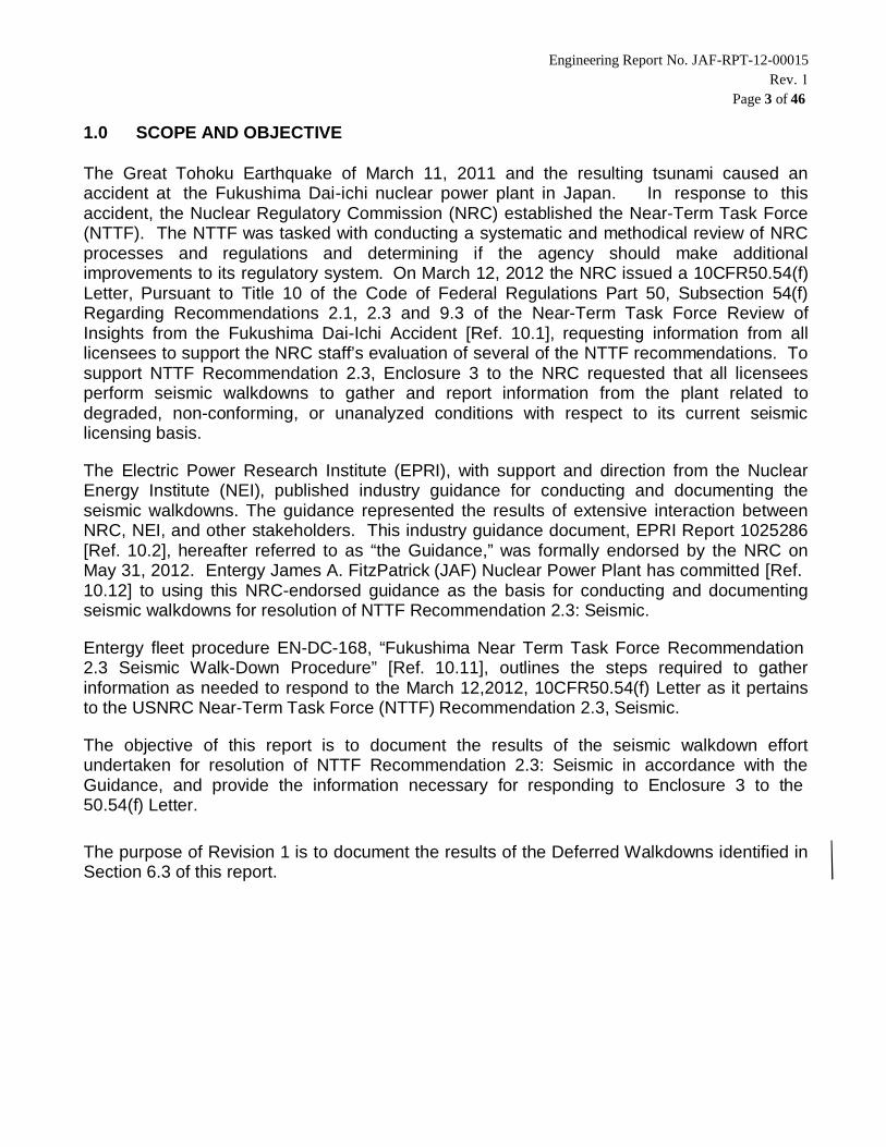
1.0 SCOPE AND OBJECTIVE
The Great Tohoku Earthquake of March 11, 2011 and the resulting tsunami caused anaccident at the Fukushima Dai-ichi nuclear power plant in Japan. In response to thisaccident, the Nuclear Regulatory Commission (NRC) established the Near-Term Task Force(NTTF). The NTTF was tasked with conducting a systematic and methodical review of NRCprocesses and regulations and determining if the agency should make additionalimprovements to its regulatory system. On March 12, 2012 the NRC issued a 10CFR50.54(f)Letter, Pursuant to Title 10 of the Code of Federal Regulations Part 50, Subsection 54(f)Regarding Recommendations 2.1, 2.3 and 9.3 of the Near-Term Task Force Review ofInsights from the Fukushima Dai-Ichi Accident [Ref. 10.1], requesting information from alllicensees to support the NRC staff’s evaluation of several of the NTTF recommendations. Tosupport NTTF Recommendation 2.3, Enclosure 3 to the NRC requested that all licenseesperform seismic walkdowns to gather and report information from the plant related todegraded, non-conforming, or unanalyzed conditions with respect to its current seismiclicensing basis.
The Electric Power Research Institute (EPRI), with support and direction from the NuclearEnergy Institute (NEI), published industry guidance for conducting and documenting theseismic walkdowns. The guidance represented the results of extensive interaction betweenNRC, NEI, and other stakeholders. This industry guidance document, EPRI Report 1025286[Ref. 10.2], hereafter referred to as “the Guidance,” was formally endorsed by the NRC onMay 31, 2012. Entergy James A. FitzPatrick (JAF) Nuclear Power Plant has committed [Ref.10.12] to using this NRC-endorsed guidance as the basis for conducting and documentingseismic walkdowns for resolution of NTTF Recommendation 2.3: Seismic.
Entergy fleet procedure EN-DC-168, “Fukushima Near Term Task Force Recommendation2.3 Seismic Walk-Down Procedure” [Ref. 10.11], outlines the steps required to gatherinformation as needed to respond to the March 12,2012, 10CFR50.54(f) Letter as it pertainsto the USNRC Near-Term Task Force (NTTF) Recommendation 2.3, Seismic.
The objective of this report is to document the results of the seismic walkdown effortundertaken for resolution of NTTF Recommendation 2.3: Seismic in accordance with theGuidance, and provide the information necessary for responding to Enclosure 3 to the50.54(f) Letter.
The purpose of Revision 1 is to document the results of the Deferred Walkdowns identified inSection 6.3 of this report.

Engineering Report No. JAF-RPT-12-00015 Rev. 1
Page 4 of 46
2.0 SEISMIC LICENSING BASIS SUMMARY
JAF is a single unit BWR-4 (Boiling Water Reactor) with a Mark I containment, located inOswego County, New York. General Electric (GE) designed the nuclear steam supply systemand the turbine-generator. Stone & Webster was the Architect/Engineer for the plant. JAFbegan commercial operation in July of 1975, and is currently rated at 2,536 MWt power [Ref.10.3, Section 1.2] and has a rated gross electrical output of approximately 881 MWe whenoperating at full power. This section summarizes the seismic licensing basis of structures,systems and components (SSCs) at JAF, which bound the context of the NTTF 2.3 SeismicWalkdown program.
2.1 SAFE SHUTDOWN EARTHQUAKE (SSE)
The seismic design for Class I structures (including the reactor building and all engineeredsafeguards) is based on dynamic analysis using acceleration response spectrum curveswhich are normalized to a ground motion of 0.08 g, for the Operating Basis Earthquake, and0.15 g, for the Design Basis Earthquake. The basis of this design criterion is presented inReference 10.3, Section 2.6. Class I seismically designed structures may be referred to as"Seismic Class I" structures [Ref. 10.3, Section 12.4.6.1].
The horizontal seismic forces were determined using a lumped mass frequency responseanalysis considering flexural, translational and rocking (in some cases) response. Theseanalyses take into account rock-structure interaction.
The vertical response spectrum is assumed to be two-thirds the horizontal responsespectrum of each earthquake and is considered to act simultaneously. Where applicable, thestresses are added directly.
The damping value of 2 percent of critical for concrete structures under Operating BasisEarthquake is less than the range of 3 to 5 percent for design within code allowable stressesrecommended by Newmark and Hall in their paper "Design Criteria for Nuclear ReactorsSubject to Earthquake Hazards." Under the Operating Basis Earthquake, the stresses arewithin the allowable code stresses; therefore, little cracking will occur in the concrete.
Newmark suggests a value of 7 to 10 percent of critical damping for stress levels at or justbelow yield point. To be conservative and minimize cracking in the concrete under the DesignBasis Earthquake, 5 percent of critical damping is used.
Horizontal and vertical displacements due to Operating Basis and Design Basis Earthquakesare determined for all Class I structures. Based on calculated displacements, adequate spaceis provided between adjacent structures to ensure that basic structural elements do not strikeeach other when subjected to the worst combination of rocking, bending and sheardeflections and translation movements that might be induced by an earthquake. All Class I

Engineering Report No. JAF-RPT-12-00015 Rev. 1
Page 5 of 46
systems passing between adjacent structures are designed to withstand the maximumcombination of movement between the adjacent structures without loss of function. The effectof the relative movement between buildings is considered in the piping stress analysis and inthe design and location of supports.
2.2 DESIGN CODES, STANDARDS, AND METHODS
Class I structures and equipment are those that are necessary to ensure: a) the integrity ofthe reactor coolant pressure boundary, b) The capability to shut down the reactor andmaintain it in a safe, shutdown condition, or c) the capability to prevent or mitigate theconsequences of accidents that could result in potential off-site exposures comparable to theguidelines of 10 CFR 100. Class II structures and equipment are those which may beessential to operation of the plant, but are not included in Class I. Class III structures andequipment are those that are not included in Class I or Class II. A "Component QualityAssurance Category List" further defines "Class I", "Class II", or "Class III" structures,systems, and components as "Quality Assurance" (QA) SR, QP, or NSR. QA Categories SR,QP and NSR are synonymous with the previously used I, M and II/III (or II or III separately)categories, respectively. [Ref. 10.3, Section 12.2.1].
The Reference 10.8 document provides the basic criteria for the safety related Balance ofPlant (BOP) pipe stress analysis and pipe support qualification and/or design for theJAFNPP. BOP piping systems are those systems which are not part of the General Electric(GE) Nuclear Steam Supply System (NSSS). A listing of the seismically qualified BOP pipelines is provided in Reference 10.8, Section 7.0.
Class IE - The safety classification of the electric equipment and systems, including theirsupporting systems that are essential to emergency reactor shutdown, containment isolation,reactor core cooling, and containment and reactor heat removal, or otherwise are essential inmitigating the consequences of an accident [Ref. 10.10].
Mechanical Equipment and Piping Code Applicability
USAS (ANSI) B31.1, 1967 Edition through 1969 Addenda, Power Piping Code.
ASME Boiler and Pressure Vessel Code for Nuclear Vessels, Section III, SubsectionB, 1968 Edition including the 1968 Summer Addendum.
Pipe Support Code Applicability
USAS (ANSI) B31.1, 1967 Edition through 1969 Addenda, Power Piping Code.
AISC Specification for Design, Fabrication, and Erection of Structural Steel forBuildings.

Engineering Report No. JAF-RPT-12-00015 Rev. 1
Page 6 of 46
Applicable USNRC Regulatory Guides
Because JAFNPP was designed before the establishment of Regulatory Guides, noRegulatory Guide is directly applicable. However, the Regulatory Guide 1.61, Revision O,Damping Values for Seismic Design of Nuclear Power Plants, October 1973, was used forfluid transient analyses [10.8].
The USNRC Regulatory Guide 1.92, Section 1.2.1 "The Grouping Method." [Ref. 10.3,Section 12.5.4], was used for combining modal responses in the seismic reanalysis for theWide Range and Narrow Range reactor water level piping systems.
Applicable IE Bulletins
IE Bulletin 79-02, Pipe Support Base Plate Designs Using Concrete Expansion AnchorBolts.
IE Bulletin 79-07, Seismic Stress Analysis of Safety-Related Piping.
IE Bulletin 79-14, Seismic Analysis for As-Built Safety-Related Piping Systemsincluding all supplements.
IE Bulletin 80-11, Masonry Wall Design.
Mechanical Equipment and Equipment Support Analysis
Overall e q u i p m e n t s t r u c t u r a l r e s p o n s e i n c l u d e s l o a d s f r o mn o z z l e s , e q u i p m e n t deadweight, design pressure, operating temperature,equipment earthquake loads and other dynamic loads. Reference 10.8, Section 5.0,Tables 5.0-1 and 5.0-2A through 2E show the accepted equipment nozzle loads thatwere established during the plant design stage and later during the as-built stressanalysis effort.
The criteria, method of analysis, and summary of critical stresses for variousequipment are included in UFSAR Table 16.2-7. [Ref. 10.3]
Structures and Seismic Input to Structures and Equipment
The seismic motion induced at the pipe supports in the structure is likely to be differentfrom the ground motions. Since the various parts of the structures oscillate in differentmagnitudes and directions, the piping systems are essentially subjected to differentexcitations at each pipe anchor and restraint location. Therefore, amplified responsespectra (ARS) for the maximum acceleration at various elevations throughout thestructures are determined and the spectrum which is closest to and higher in elevationthan the center of mass of piping is used.
Engineering Report No. JAF-RPT-12-00015 Rev. 1
Page 7 of 46
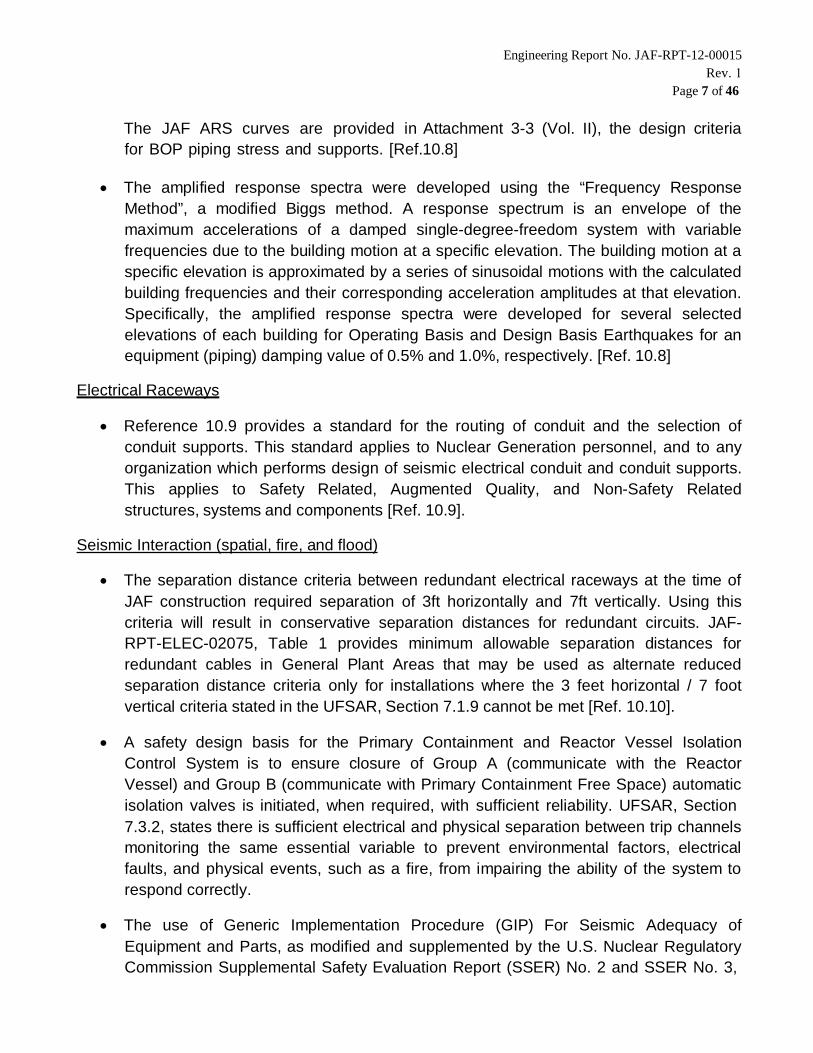
The JAF ARS curves are provided in Attachment 3-3 (Vol. II), the design criteriafor BOP piping stress and supports. [Ref.10.8]
The amplified response spectra were developed using the “Frequency ResponseMethod”, a modified Biggs method. A response spectrum is an envelope of themaximum accelerations of a damped single-degree-freedom system with variablefrequencies due to the building motion at a specific elevation. The building motion at aspecific elevation is approximated by a series of sinusoidal motions with the calculatedbuilding frequencies and their corresponding acceleration amplitudes at that elevation.Specifically, the amplified response spectra were developed for several selectedelevations of each building for Operating Basis and Design Basis Earthquakes for anequipment (piping) damping value of 0.5% and 1.0%, respectively. [Ref. 10.8]
Electrical Raceways
Reference 10.9 provides a standard for the routing of conduit and the selection ofconduit supports. This standard applies to Nuclear Generation personnel, and to anyorganization which performs design of seismic electrical conduit and conduit supports.This applies to Safety Related, Augmented Quality, and Non-Safety Relatedstructures, systems and components [Ref. 10.9].
Seismic Interaction (spatial, fire, and flood)
The separation distance criteria between redundant electrical raceways at the time ofJAF construction required separation of 3ft horizontally and 7ft vertically. Using thiscriteria will result in conservative separation distances for redundant circuits. JAF-RPT-ELEC-02075, Table 1 provides minimum allowable separation distances forredundant cables in General Plant Areas that may be used as alternate reducedseparation distance criteria only for installations where the 3 feet horizontal / 7 footvertical criteria stated in the UFSAR, Section 7.1.9 cannot be met [Ref. 10.10].
A safety design basis for the Primary Containment and Reactor Vessel IsolationControl System is to ensure closure of Group A (communicate with the ReactorVessel) and Group B (communicate with Primary Containment Free Space) automaticisolation valves is initiated, when required, with sufficient reliability. UFSAR, Section7.3.2, states there is sufficient electrical and physical separation between trip channelsmonitoring the same essential variable to prevent environmental factors, electricalfaults, and physical events, such as a fire, from impairing the ability of the system torespond correctly.
The use of Generic Implementation Procedure (GIP) For Seismic Adequacy ofEquipment and Parts, as modified and supplemented by the U.S. Nuclear RegulatoryCommission Supplemental Safety Evaluation Report (SSER) No. 2 and SSER No. 3,

Engineering Report No. JAF-RPT-12-00015 Rev. 1
Page 8 of 46
may be used as an alternative method to existing methods for the seismic design andverification of existing, modified, new and replacement equipment and parts classifiedas Class 1. Only those portions of the GIP listed in "Use of Generic ImplementationProcedure (GIP) for New and Replacement Equipment and Parts (NARE)" shall beused. The other portions of the GIP are not applicable since they containadministrative, licensing, and documentation information which is applicable only tothe Unresolved Safety Issue (USI) A-46 program [Ref. 10.3, Section 12.5.6].
Automatic water sprays, are provided in the Reactor Building at various areaboundaries to isolate fire areas from each other. The water spray piping is seismicallysupported. [Ref. 10.3, Section 9.8.3.1.4]
All fire protection water piping and mechanical equipment up to and including flowcontrol valves in the Fire Protection Systems protecting Class I systems andcomponents listed below are designed to QA Category QP criteria.
1. High Pressure Coolant Injection Pump.
2. Reactor Core Isolation Cooling Pump.
3. Emergency Diesel-Generator Rooms.
4. Diesel Driven Fire Pump.
5. Standby Gas Treatment System Charcoal Filters.
The fire protection piping for the Battery Room Corridor is seismically supported fromthe alarm check valve on manifold No. 7 through the sprinkler discharge piping. Thesystem is QA class QP, seismically supported to prevent it from interfering with anysafety related system or components in the Battery Room Corridor or Cable Tunnels.
Engineering Report No. JAF-RPT-12-00015 Rev. 1
Page 9 of 46
3.0 SEISMIC WALKDOWN PROGRAM IMPLEMENTATION APPROACH
JAF has committed, per JAFP-12-0075 [Ref. 10.12], to conduct and document seismicwalkdowns for resolution of NTTF Recommendation 2.3: Seismic in accordance with theEPRI Seismic Walkdown Guidance [Ref. 10.2]. The approach provided in the Guidance foraddressing the actions and information requested in Enclosure 3 to the 50.54(f) Letterincludes the following activities, the results of which are presented in the sections shown inparenthesis:
Assignment of appropriately qualified personnel (Section 4.0)
Reporting of actions taken to reduce or eliminate the seismic vulnerabilitiesidentified by the Individual Plant Examination of External Events (IPEEE)program (Section 5.0)
Selection of structures, systems and components (SSCs) to be evaluated(Section 6.0)
Performance of the seismic walkdowns and area walk-bys (Section 7.0)
Evaluation and treatment of potentially adverse seismic conditions with respectto the seismic licensing basis of the plant (Section 8.0)
Performance of peer reviews (Section 9.0)
The coordination and conduct of these activities was initiated and tracked by Entergycorporate leadership, which provided guidance to each Entergy site throughout the seismicwalkdown program, including JAF. Entergy contracted with an outside nuclear servicescompany to provide engineering and project management resources to supplement andassist each individual site. JAF had dedicated engineering contractors, supported by theirown project management and technical oversight, who worked closely with plant personnel.
Engineering Report No. JAF-RPT-12-00015 Rev. 1
Page 10 of 46
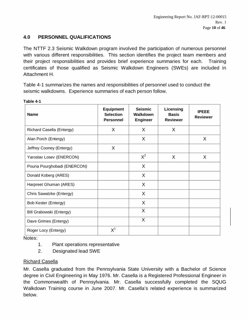
4.0 PERSONNEL QUALIFICATIONS
The NTTF 2.3 Seismic Walkdown program involved the participation of numerous personnelwith various different responsibilities. This section identifies the project team members andtheir project responsibilities and provides brief experience summaries for each. Trainingcertificates of those qualified as Seismic Walkdown Engineers (SWEs) are included inAttachment H.
Table 4-1 summarizes the names and responsibilities of personnel used to conduct theseismic walkdowns. Experience summaries of each person follow.
Table 4-1
NameEquipmentSelectionPersonnel
SeismicWalkdownEngineer
LicensingBasis
Reviewer
IPEEEReviewer
Richard Casella (Entergy) X X X
Alan Porch (Entergy) X X
Jeffrey Cooney (Entergy) X
Yaroslav Losev (ENERCON) X2 X X
Pouria Pourghobadi (ENERCON) X
Donald Koberg (ARES) X
Harpreet Ghuman (ARES) X
Chris Sawatzke (Entergy) X
Bob Kester (Entergy) X
Bill Grabowski (Entergy) X
Dave Grimes (Entergy) X
Roger Locy (Entergy) X1
Notes:1. Plant operations representative2. Designated lead SWE
Richard CasellaMr. Casella graduated from the Pennsylvania State University with a Bachelor of Sciencedegree in Civil Engineering in May 1976. Mr. Casella is a Registered Professional Engineer inthe Commonwealth of Pennsylvania. Mr. Casella successfully completed the SQUGWalkdown Training course in June 2007. Mr. Casella’s related experience is summarizedbelow.

Engineering Report No. JAF-RPT-12-00015 Rev. 1
Page 11 of 46
Mr. Casella has 36 years of experience in the Engineering Design of nuclear power plants.He spent 19 years at Stone and Webster Engineering Corporation (SWEC) associated withthe design, startup, and operation of the Nine Mile Point 2 (NMP2) station. The first 7 yearsof his career were spent in the SWEC design office as a Pipe Stress analyst for ASME IIIClass 2, 3 and USAS B31.1 Class 4 piping systems. The remaining 12 years of his SWECservice were spent at NMP2 in Lycoming, NY. During this time, Mr. Casella was a PipeStress supervisor, then Lead Engineer for Pipe Stress and Supports, and then supported thetransition of design responsibilities from SWEC to the Niagara Mohawk Power Corporation(NMPC). After plant startup, Rick worked as a Civil/Structural Design Engineer under NMPCauthority until 1995.
Mr. Casella joined the New York Power Authority in October 1995 as a Civil/Structural DesignEngineer at the James A. FitzPatrick (JAF) plant. His primary role in his 17 year tenure atJAF has been pipe stress. He has worked with ISI Class 1, 2, 3 and non-ISI piping. He hasbeen involved with and has an understanding of the Mark I Containment work performed forJAF by the Teledyne Corporation. He has dealt with numerous seismic piping issues at JAFincluding many times assisting the Shift Manager with Operability determinations related toseismic piping and support issues. Mr. Casella has worked 9 Refuel Outages and severalLCOs at JAF which have given him valuable “hands and eyes on” experience and knowledgeof the plant and how it operates. Rick has also been associated with many plantmodifications with seismic evaluations and calculations including Responsible Engineer forthe replacement of 2-Stage Main Steam Safety Relief Valves with 3-Stage models. He isalso experienced in Seismic Qualification of plant equipment and the Boiling Water ReactorVessel Internals Program (BWR-VIP).
Alan PorchMr. Porch graduated from the Drexel University with a Bachelor of Science degree in CivilEngineering in June 1974. He is a Registered Professional Engineer in the State of NewYork. Al successfully completed the EPRI Training on Near Term Task ForceRecommendation 2.3 – Plant Seismic Walkdowns in July 2012.
Mr. Porch has 34 years of experience in the Engineering Design of nuclear power plants. Hespent 13 years at Stone and Webster Engineering Corp. (SWEC) associated with the design,startup support, and operation of the Nine Mile Point 2 (NMP2) Station. The first year of hiscareer was spent in the SWEC design office as a structural design engineer performing steeland concrete design activities associated with the design of the Nine Mile Point NPP. Thenext 5 years he worked at the Fermi II NPP as a pipe support design engineer and theremaining 7 years of his SWEC service were spent at NMP2 in Lycoming, NY. During thistime, Mr. Porch was a Pipe Support engineer and Modification engineer, and then supportedthe transition of design responsibilities from SWEC to the Niagara Mohawk PowerCorporation (NMPC). After plant startup, Al worked as a Civil/Structural Design Engineerunder NMPC authority until 1995.

Engineering Report No. JAF-RPT-12-00015 Rev. 1
Page 12 of 46
Mr. Porch joined the New York Power Authority in September 1995 as a Civil/StructuralDesign Engineer at the James A. FitzPatrick (JAF) plant. His primary role in his 17 yeartenure at JAF has been structural design support with a special attention given to pipesupport design and acceptance. He has worked with ISI Class 1, 2, 3 and non-ISI pipingsystems. He has dealt with numerous seismic piping issues at JAF including assisting theShift Manager with Operability determinations related to seismic piping and support issues.Mr. Porch has worked 9 Refuel Outages as well as forced outages and down powers and atJAF which have given him valuable “hands and eyes on” experience and knowledge of theplant and how it operates. Al has also been associated with many plant modifications withhave included seismic evaluations and calculations including performing as ResponsibleEngineer for JAF’s Pipe Support Program.
Jeffrey Cooney
Mr. Cooney is employed as a PSA Engineer for Entergy Nuclear Operations. He has beenemployed with the company over 4 years. His expertise is in Probabilistic Safety Assessment(PSA) which includes maintaining/updating the active site PSA model and ensuring thatcurrent industry standards, experience, and technology are incorporated appropriately intothe model.
Yaroslav LosevMr. Losev graduated from the New Jersey Institute of Technology with a Bachelor of Sciencedegree in Mechanical Engineering in June 2008. He has worked as an ENERCONMechanical Engineering for three years. For the past 2 years, he has been working in theStructural Engineering department. Mr. Losev has successfully completed Training on NearTerm Task Force Recommendation 2.3 Plant Walkdowns in 09/13/2012. Some of Mr. Losev’srelated experience has been summarized below.
As part of Exelon’s ongoing commitments to comply with the Nuclear Regulatory Commission(NRC) requirements for post-fire safe shutdown promulgated in 10CFR50 certain scenarioshave been identified by the Exelon Expert Panel that are related to the safe shutdown ofLimerick Generating Station (LGS). Plant design changes are required to address issuesrelated to Multiple Spurious Operations (MSOs) as outlined in Nuclear Energy Institute (NEI)00-01, Rev. 2 (Guidance for Post-Fire Safe Shutdown Circuit Analysis) and ensurecompliance with NRC Regulatory Guide 1.189, Rev 2 (Fire Protection for Nuclear PowerPlants). Mr. Losev prepared technical evaluations and revised existing plant calculations onthe capacity of existing raceway supports to support the additional dead weight load of thefire barrier systems including seismic requirements and considerations. He also developedtechnical evaluations for seismic temporary supports in number of other locations at LGS.
Engineering change package implementation in Indian Point (IPEC), Units 2 and 3, coating ofthe walls of the transformer moats for Main Transformers. During the stone removal to install

Engineering Report No. JAF-RPT-12-00015 Rev. 1
Page 13 of 46
coating, various existing non-safety related conduits and pipes had to be temporarilysupported as part of this work activity. The supports were temporarily attached to existingstructural steel and the steel columns, beams and foundations which were evaluated for theadditional load. Mr. Losev designed and evaluated 27 uniquely different temporary supportsto be installed while the stone was removed. Mr. Losev demonstrated extreme flexibility andimagination in designing these supports. He also showed technical rigor, fast adaptation tonew designs into evaluation, clear client communications, and timely deliverable of thecalculation despite fast track schedule of this project.
Mr. Losev provided support in walkdowns and design inputs for Honeywell at MetropolisWorks (MTW) UF6 Processing Facility in determination and suggestions of seismic supportsfor their piping systems and equipment. He reviewed seismic calculations on equipment andprovided conceptual designs for supports on the equipment and piping runs to meet NRC’srequirements.
Mr. Losev provided mechanical/structural engineering support for American Electrical Power(AEP) D.C. Cook Generating Station on “Pipe Stress Analysis” re-evaluation. As part of D.C.Cook Generating Station’s Large Bore Pipe Reconciliation Project (LBPRP), numerous safetyrelated pipe stress calculations had to be re-evaluated. The objective of these calculationswas to structurally qualify the piping, pipe supports, including integral welded attachments,penetrations/nozzles, and valve accelerations in accordance with the design limits for deadweight, thermal, flow transients, and seismic conditions, and to provide the technical basis forany recommended modifications to the system that would be required to meet the D.C. CookGenerating Station’s acceptance criteria.
Pouria PourghobadiMr. Pourghobadi has worked as an ENERCON Civil/Structural Engineer for the past year. Mr.Pourghobadi has successfully completed Training on Near Term Task ForceRecommendation 2.3 Plant Walkdowns in 09/13/2012. Some of Mr. Pourghobadi’s relatedexperience has been summarized below.
As part of commitment to NRC, the Zion Solutions contracted ENERCON to provideArchitectural and Engineering (A/E) Services for the design of an Independent Spent FuelStorage Installation (ISFSI), various Fuel Handling Building modifications and operations. Mr.Pourghobadi reviewed calculations and drawings for a new set-down pad with a loadedMAGNASTOR Transfer CASK (MTC) in the lower level of the Reactor Building cavity floorand evaluation of the capacity of existing floor slab to support the additional dead weight loadwith seismic requirements and considerations of the loaded MTC.
Mr. Pourghobadi provided civil/structural engineering support to Exelon Peach Bottom AtomicPower Station (PBAPS) to design a 75 ft high lighting arrestor as part of an EngineeringChange Package. Site unique topography dictated adoption of a more creative approach

Engineering Report No. JAF-RPT-12-00015 Rev. 1
Page 14 of 46
rather than the conventional methods of mast foundation design. Mr. Pourghobadi provideddesign inputs for development of the foundation and evaluated the dead load of the lightingarrestor onto the foundation design.
Donald Koberg
Mr. Koberg earned a Bachelor’s degree from Washington State University in MechanicalEngineering in 2010. He has been working as a Mechanical Engineer at ARES Corporationfor over 2 years. Throughout his two plus years at ARES Corporation he has performed manytechnical calculations relating to anchorage and support design of piping systems for seismicactivities. Mr. Koberg has successfully completed Training on Near Term Task ForceRecommendation 2.3 Plant Walkdowns on 07/26/2012. Some of Mr. Koberg’s relatedexperience is summarized below.Mr. Koberg’s experience with anchorage design consists of designing and analyzinganchorage of piping support system to ASME B31.3 requirements. Tasks included selectionof material, support configuration, and general layout design of the pipe supports for stainlesssteel piping for use in waste retrieval activities at the Hanford Nuclear Reservation, Hanford,WA. Mr. Koberg has also analyzed various systems, structures and components foradherence to ASME B31.3, “Process Piping”.Mr. Koberg’s activities include design and analysis of waste transfer piping systems includingassisting on equipment design and system analysis. As part of the ASME B31.3 analyses,Mr. Koberg as analyzed multiple sections of piping systems and their supports for structuraladequacy during seismic events. Analyzed equipment includes pump assemblies, wastedistribution assemblies, and stainless steel piping assemblies.
Harpreet Ghuman
Mr. Ghuman earned a Bachelor’s degree from Washington State University in CivilEngineering in 2008. He has been working as a Structural Engineer at ARES Corporation forthe past 4 years. Throughout his four years at ARES Corporation he has performed manytechnical calculations relating to anchorage design, footing/slab design, and pipe supportdesign for seismic activities. Mr. Ghuman has successfully completed Training on Near TermTask Force Recommendation 2.3 Plant Walkdowns on 07/26/2012. Some of Mr. Ghuman’srelated experience is summarized below.Mr. Ghuman’s experience in anchorage design consists of designing expansion or cast inplace threaded rod/headed anchors for placement within concrete of various thicknesses andedge distance constraints in accordance with ACI-318, Appendix D. Also included withinanchorage design is the design of at grade or embedded base plates. Mr. Ghuman also hasexperience in designing welds for mechanical supports. Mr. Ghuman’s footing/slab designexperience consists of designing the appropriate size concrete foundation including rebar forvarious mechanical supports.

Engineering Report No. JAF-RPT-12-00015 Rev. 1
Page 15 of 46
Mr. Ghuman has experience in Near Term Task Force Recommendation 2.3 PlantWalkdowns. He was part of a team that performed these walkdowns for Duke Energy at theMcGuire Nuclear Station Units A and B near Huntersville, NC from August 27, 2012 thruSeptember 13, 2012. Mr. Ghuman’s responsibilities during these walkdowns consisted ofaiding in filling out the Area Walk-by (AWC) and Seismic Walkdown Checklists (SWC) forvarious areas and equipment within the plant. He also assisted in the preparation ofpackages, such as finding drawings/calculations that pertained to equipment on the SeismicWalkdown Equipment List (SWEL), and determined which components should be consideredas part of the required 50% design verification components in accordance with EPRI Report1025286.Mr. Ghuman has worked in Hanford, WA on the contaminated groundwater in the 100 areasthat reactor sites were required to be treated then pumped back into the river basin. Mr.Ghuman’s task was for these projects was to design pipe supports for the piping line to allowfor safe distribution of contaminated water during seismic or wind events. The designincluded, fabricating members from structural steel which includes weld and bolt design orconstructing pipes supports out of UNISTRUT members. Mr. Ghuman also designedconcrete foundations and sized the appropriate expansion or cast in place anchors for thepipe supports or various other mechanical equipment.
Chris Sawatzke
Mr. Sawatzke graduated from Michigan State University with a Bachelor of Science degree inCivil Engineering in September 1981. He has an Engineer-In-Training (EIT) in the State ofMichigan. Chris successfully completed the EPRI Training on Near Term Task ForceRecommendation 2.3 – Plant Seismic Walkdowns in July 2012. He has also successfullycompleted EPRI Training on Visual Examination Level II – Containment Inspection Programin September 2005 and the EPRI Comprehensive Coating Training in April 2002.Mr. Sawatzke has 31 years of experience in the Engineering Design of nuclear power plants.He spent 13 years with Niagara Mohawk associated with the design and operation of theNine Mile Point – Unit 2 Nuclear Plant. The first seven years of his career were spentworking for Gilbert/Commonwealth at Washington Power Unit 2, Perry Nuclear Plant Unit 1,Browns Ferry Nuclear Power Plant and Sequoyah Nuclear Power Plant; and Nuclear PowerServices (NPS) at South Texas Project Nuclear Plant. During this time, Mr. Sawatzke was aDesign Engineer supporting the Civil/Structural Engineering Department performing steel andconcrete design activities associated with the design of each of the specific nuclear powerplants.Mr. Sawatzke joined Entergy Nuclear Operations in October 2001 as a Senior Civil/StructuralDesign Engineer at the James A. FitzPatrick (JAF) Nuclear Power Plant. His role in his 11year tenure at JAF has been structural steel and concrete design for Systems, Structures andComponent’s (SSC’s). He has worked with ISI Class 1, 2, 3 and Non-ISI piping systems. Hehas dealt with numerous seismic piping and structural issues at JAF including assisting the

Engineering Report No. JAF-RPT-12-00015 Rev. 1
Page 16 of 46
plant Shift Manager with Operability Determinations related to seismic piping and pipe supportissues. Mr. Sawatzke has worked 6 Refuel Outages as well as forced outages and downpowers at JAF, 5 refuel outages at other Entergy Fleet plants, and 7 refuel outages as well asforced outages at Nine Mile Nuclear Plant Unit 2; which has provided him valuable “hands on”experience and knowledge of the various plants and systems and how they operate. Mr.Sawatzke has also been associated with many plant modifications as a Responsible Engineerwhich included seismic evaluations and formal calculations for the JAF Pipe SupportProgram.
Bob Kester
Mr. Kester graduated from Lafayette College with a Bachelor of Science degree in CivilEngineering in May 1980. Mr. Kester successfully completed the SQUG Walkdown Trainingcourse in August 1993, and performed SQUG USI A-46 walkdowns for James A. FitzpatrickNuclear Plant in 1995.
Mr. Kester has 32 years of experience in the Engineering Design of nuclear power plants. Hespent 10 years at Stone and Webster Engineering Corporation (SWEC) associated with thedesign of the River Bend and Nine Mile Point 2 (NMP2) stations. During this period, Bob’sexperience was primarily associated with pipe stress and support design, and included over 8years as a field engineering, which provided valuable experience that integrated aspects ofdesign criteria, design changes, construction and inspection requirements.
Mr. Kester’s career shifted to an operating nuclear power station, working for the utilitycompany at the James A. FitzPatrick (JAF) plant since December 1989. In addition to beinginvolved in Plant Modification designs and the JAF SQUG program, Bob has had diverseexperiences in civil, structural, and mechanical engineering disciplines as a Plant Engineer.This role has often required a practical approach to seismic evaluations in support ofOperability determinations related to plant condition reports. Mr. Kester has workednumerous plant Refuel Outages and system LCOs at JAF which have given him valuable“hands and eyes on” experience and knowledge of the physical plant, and how it operatedand maintained. Bob’s involvement with numerous plant modifications has included seismicevaluations for structures, piping, tubing, raceways, and miscellaneous equipment, which hasentailed formal design calculations, simplified qualitative evaluations, and also the use ofEPRI’s GIP & STERI methodology. For over 15 years in a Plant Support Engineering group,Bob has been the primary responsible engineer at JAF for structural evaluations of temporaryconditions in the plant including scaffolding, shielding, leak repairs, freeze seals, as well asstaging & storage of transient equipment.
Engineering Report No. JAF-RPT-12-00015 Rev. 1
Page 17 of 46Bill Grabowski
Mr. Grabowski is a Civil engineer with over 4 years of experience in the nuclear powerindustry. He holds a Bachelor of Science degree in Civil Engineering from SyracuseUniversity. Mr. Grabowski is currently a level III Civil/Structural/Mechanical Design Engineerfor JAF. His primary duties at JAF include technical oversight of contracted design projectsand serving as design engineer for Civil/Structural/Mechanical projects developed in-house.He has performed design related work for JAF nuclear Power Station for more than 4 years.He is also responsible for the programmatic monitoring of structures to meet the requirementsof the Maintenance Rule Inspection Program, the Coatings program Owner, and theResponsible Engineer for the Independent Spent Fuel Storage Installation.
For this project, Mr. Grabowski completed deferred walkdowns during the 2014 outage.
Dave Grimes
Mr. Grimes is a Civil engineer with over 29 years of experience in the nuclear power industry.He holds a Bachelor of Science and Masters of Science degrees in Civil Engineering from theNortheastern University (Boston MA). Mr. Grimes is currently a SeniorCivil/Structural/Mechanical Design Engineer for Vermont Yankee. His primary duties atVermont Yankee include technical oversight of contracted design projects and serving asdesign engineer for Civil/Structural/Mechanical projects developed in-house. He hasperformed design related work for Vermont Yankee Nuclear Power Station for more than 25years. He is also responsible for the programmatic monitoring of structures to meet therequirements of the Maintenance Rule Inspection Program.
For this project, Mr. Grimes completed deferred walkdowns during the 2014 outage.
Roger LocyMr. Locy’s education and training is summarized as follows: Machinist Mate "A" School, U.S.Navy, completed May 1966. Basic Nuclear Power School, U.S. Navy, completed April 1967.Naval Reactor Prototype, U.S. Navy, completed October 1967. BWR Technology, GeneralElectric, completed December 1972. Site training programs, Duane Arnold Energy Center.Numerous courses for RO cold license and requalification. License number OP-3424. Sitetraining programs, Duane Arnold Energy Center. Numerous courses for SRO license andrequalification. License Number SOP-2849. Site training programs, James A. FitzPatrickNuclear Power Plant. Numerous courses for SRO license and requalification. Licensenumber SOP-3218. Regents College, The University of the State of New York. Presentlyhave earned 110 credits toward a Baccalaureate Degree in Nuclear Technology.

Engineering Report No. JAF-RPT-12-00015 Rev. 1
Page 18 of 46
From November 1967 to April 1972, U.S.S. Enterprise-Nuclear Powered Aircraft Carrier.From May 1972 to July 1977, Operations Department, Duane Arnold Energy Center. FromAugust 1977 to February 1982, Shift Supervisor, James A. FitzPatrick Nuclear Power Plant.From March 1982 to March 1985, Waste Management General Supervisor, James A.FitzPatrick Nuclear Power Plant. Established Decontamination and Shipping section ofRadiological Waste Group in the Operations Department. Responsible for operation of theRadwaste Facility, all Radwaste shipments for disposal and area/equipmentdecontamination. From April 1985 to March 1989, Assistant Operations Manager, James A.FitzPatrick Nuclear Power Plant. Assisted the Operations Manager with the day to dayoperations of the plant. From April 1989 to March 1997, Operations Manager, James A.FitzPatrick Nuclear Power Plant. Responsible for the safe and efficient operation of the plant.Provide management over view of operating shifts, operation support and Radwaste Facilityoperation. Held a SRO license. From March 1997 to November 2000, Training Manager,James A. FitzPatrick Nuclear Power Plant. Responsible for the design, development,implementation and evaluation of training programs ensuring regulatory compliance, costeffectiveness and plant staff qualification. From November 2000 to June 2006, ProjectManager Operations Support, FitzPatrick Nuclear Power Plant, responsible for operationsinput to outage planning, maintenance rule operations representative, BWROG ScramFrequency Reduction Committee representative, perform root cause analysis for departmentevents and operations department training coordinator. From September 2006 to April 2007,Project Manager Operations Training Improvement Program, Ginna Nuclear Power Station.Responsible for the completion of the Operations Training Excellence Plan completion.Monitored both quality and timeliness of action close out. Oversight of a Operation LessonPlan Upgrade Program. Supervised 5 contract lesson plan developers. From October 2007 toAugust 2009, Operations Procedure Group Lead, Nine Mile Point Nuclear Station.Responsible for the development and maintenance of all Operations Procedures for bothunits. Oversight of the WordPerfect to Word conversion of all site procedures. Revisedprocedures to support outage activities and modifications. From November 2009 to Present,License Renewal Project Senior Project Manager, James A. FitzPatrick Nuclear Power Plant.Responsible for identification, performance and documentation of One-Time Inspections.Assisted with monitoring progress of completion of NRC License Renewal Commitments.

Engineering Report No. JAF-RPT-12-00015 Rev. 1
Page 19 of 46
4.1 EQUIPMENT SELECTION PERSONNEL
A total of 3 individuals served as Equipment Selection Personnel – see Table 4-1.
4.2 SEISMIC WALKDOWN ENGINEERS
A total of 10 individuals served as Seismic Walkdown Engineers – see Table 4-1.
4.3 LICENSING BASIS REVIEWERS
A total of 2 individuals served as Licensing Basis Reviewers – see Table 4-1.
4.4 IPEEE REVIEWERS
A total of 2 individuals served as IPEEE Reviewers – see Table 4-1.
4.5 PEER REVIEW TEAM
Table 4-2 summarizes the names and responsibilities of personnel used to conduct peerreviews of the seismic walkdown program. Experience summaries of each person follow.
Table 4-2
Name SWEL PeerReviewer
WalkdownPeer
Reviewer
LicensingBasis PeerReviewer
SubmittalReport Peer
Reviewer
Tom Panayotidi (ENERCON) X2 X1,2
Alan Porch (Entergy) X X
Richard Sullivan (Entergy) X2
Laura Maclay (ENERCON) X X
Jeffrey Horton (ENERCON) X2
Richard Casella (Entergy) X
Robert Kester (Entergy) X
Bill Grabowski (Entergy) X X
Notes:1. Peer Review Team Leader2. Lead peer reviewer of particular activity

Engineering Report No. JAF-RPT-12-00015 Rev. 1
Page 20 of 46
Tom Panayotidi
Dr. Panayotidi has graduated with a Doctorate of Engineering Science in CivilEngineering/Engineering Mechanics, with emphasis in finite element analysis, particularly forseismic and other dynamic loads.
He has worked as an ENERCON Civil/Structural Consulting Engineer for the pastyear, and has successfully completed Training on Near Term Task ForceRecommendation 2.3 Plant Walkdowns on 09/13/2012. Dr. Panayotidi has over 30 years’experience as a Structural/Seismic Engineer in the nuclear field. Some of his relatedexperience is summarized below.Dr. Panayotidi prepared submittal report for OPPD Fort Calhoun Station per NTTFRecommendation 2.3: Seismic. He reviewed calculations and drawings for the OPPD FortCalhoun Station Flood Recovery and Geotechnical/Seismic Evaluation.Dr. Panayotidi also has experience in Standard Plant Design of Nuclear Island for MitsubishiHeavy Industries – US Advanced Pressurized Water Reactor: Seismic Soil-StructureInteraction Analysis of Reactor Building Complex, Foundation Stability for sliding, overturning,bearing pressure (uplift condition), shear key design, nonlinear transient displacementcalculation to predict foundation sliding, and Slope stability under seismic loading.Dr. Panayotidi also has experience in Standard Plant Design of new generation compact 125MW nuclear station for B&W mPower Project: Seismic Soil-Structure-Interaction analysis ofunderground (buried) nuclear island, he development of ground motion synthetic time historyfrom high frequency CEUS design spectrum, as well as NRC 1.60 spectrum, and generationof in-structure-response-spectra (ISRS).Dr. Panayotidi performed evaluation for NPPD Cooper Nuclear Station. He providedanalytical review of the Reactor Building Crane Upgrade: Re-rate analysis of Cooper NuclearStation Reactor Building, due to an increase in refueling crane capacity. He also evaluatedReactor building integrity for all applicable loads, including earthquake, tornado, seismic, andcrane lifted loads.Dr. Panayotidi developed worked on Accelerator Production of Tritium, DOE, for SavannahRiver Site: Seismic analysis of reinforced concrete building, including 3-D soil-structureinteraction effects due to 60ft embedment, using SASSI. He also performed calculation ofstrained (iterated) soil properties, convolution and de-convolution of input motion usingSHAKE91. Dr. Panayotidi also performed seismic anchor motion and soil-structure-interaction analysis of 1-mile long underground accelerator tunnel.Dr. Panayotidi worked on design of 250 MW single-shaft, in-line gas turbine/steamturbine/generator concrete pedestal for River Road Generating Project (WA), includingdesign of batter and vertical foundation piles, steel framing to support hot/cold piping ingeneration building.

Engineering Report No. JAF-RPT-12-00015 Rev. 1
Page 21 of 46Richard SullivanMr. Sullivan graduated from University of Tennessee with a Bachelor of Science degree inElectrical Engineering. Some of Mr. Sullivan’s related experience and awards aresummarized below.Navy Achievement Medal for superior management of the ship’s Quality Assurance Programduring two heavy maintenance periods.Extensive experience in the operation and maintenance of a variety mechanical and electricalsystems including: steam systems, cooling water systems, hydraulic systems, atmosphericcontrols, ventilation systems, electrical distribution, digital and logic systems, and electricalgeneration.From January, 2001 to September, 2007 and from October, 2007 to present, in James A.FitzPatrick Nuclear Power Plant, Mr. Sullivan coordinated and developed Operationsschedule activities and tagout preparation. Contributed to INPO 1 rating in 2004 byoutstanding simulator scenarios and professional shift operations. Aided in the development,implementation, and enforcement of high operational standards. Contributed to the recordbreaking capacity factor year at JAF in 2001. Developed plant startup procedures in a flowchart format on own initiative. From May, 1997 to December, 2000, Mr. Sullivan developedand implemented three site-wide Emergency Plan Drills which included scenario design andsimulator interface. Coordinated with other departments in the development of plantEmergency Operating Procedures and Severe Accident Procedure. Developed JAF licensedoperator annual requalification examination. From November, 1994 to April, 1997, Mr.Sullivan assisted in two error-free refueling outages as Refuel Floor SRO. In October, 1994Mr. Sullivan earned Senior Reactor Operator License from the Nuclear RegulatoryCommission.From 1988 to February, 1992, in the United States Navy, Mr. Sullivan served on board USSNevada (SSBN-733) as Tactical Systems Department Head, Strategic Missiles Officer, andDamage Controls Assistant. Quality Assurance Officer: Coordinated ship’s force and shipyardmaintenance on various systems on a Trident submarine ensuring all specifications weremet. Also responsible for training 30 personnel ship-wide.
Laura Maclay
Ms. Maclay has over five years of experience as a structural engineer, three years withENERCON Services. Ms. Maclay holds a Bachelor’s degree in Structural Engineering fromDrexel University and is a qualified Seismic Walkdown Engineer as stated on her EPRItraining certificate dated July 26, 2012. Her tasks have ranged from assisting with thedevelopment and preparation of design change packages to performing design calculationsand markups, comment resolutions, and drawing revisions. Ms. Maclay spent a year on siteat Turkey Point Nuclear Plant preparing structural evaluations of SSC’s for an ExtendedPower Uprate (EPU). Her work included designing safety related supports for computer andelectrical equipment for the Turbine Digital Controls Upgrade package and other similarpackages.

Engineering Report No. JAF-RPT-12-00015Rev. 1
Page 22 of 46Ms. Maclay’s responsibilities also included the review of calculations, drawings and vendordocumentation for the seismic evaluation of the Unit 3 Palfinger Crane inside containmentand new platforms in the High Pressure Turbine enclosure. Recent work includesFukushima flooding walkdowns at Limerick Generating Station and seismic walkdowns atPlant Farley. As a member of a two person team, Ms. Maclay was responsible forevaluating equipment anchorage, spatial interactions and potentially adverse conditions.
Jeffrey HortonMr. Horton is a Licensed Professional Engineer with 39 years of experience in the structuraldesign of nuclear power components, pipe systems and building structures. Mr. Horton iscurrently employed as a Lead Civil/Structural Engineer. He holds a B.S. in AerospaceEngineer from Park’s College of St Louis University in Missouri and a M.S. in MaterialScience specializing in Solid Mechanics from Rutgers University in New Jersey. He is aqualified SWE with extensive experience in the seismic design of components and pipesystems in Nuclear power plants.

Engineering Report No. JAF-RPT-12-00015 Rev. 1
Page 23 of 46
5.0 IPEEE VULNERABILITIES REPORTING
During the IPEEE program in response to NRC Generic Letter 88-20 [Ref. 10.4], plant-specific seismic vulnerabilities were identified at many plants. In this context, “vulnerabilities”refers to conditions found during the IPEEE program related to seismic anomalies, outliers, orother findings.
IPEEE Reviewers (see Section 4.4) reviewed the IPEEE final report [Ref. 10.5] andsupporting documentation to identify items determined to present a seismic vulnerability bythe IPEEE program. IPEEE Reviewers then reviewed additional plant documentation toidentify the eventual resolutions to those seismic vulnerabilities not resolved by thecompletion of the IPEEE program.
The seismic vulnerabilities identified for JAF during the IPEEE program are reported inAttachment A. A total of 1 seismic vulnerability was identified by the JAF IPEEE program.For the identified seismic vulnerability, the table in Attachment A includes three pieces ofinformation requested by Enclosure 3 of the 50.54(f) Letter:
A description of the action taken to eliminate or reduce the seismic vulnerability
Whether the configuration management program has maintained the IPEEE action(including procedural changes) such that the vulnerability continues to be addressed
Date when the resolution actions were completed.
The list of IPEEE vulnerabilities provided in Attachment A was used to ensure that someequipment enhanced as a result of the IPEEE program were included in SWEL1 (see Section6.1.2). Documents describing these equipment enhancements and other modificationsinitiated by identification of IPEEE vulnerabilities were available and provided to the SWEsduring the NTTF 2.3 Seismic Walkdowns.

Engineering Report No. JAF-RPT-12-00015Rev. 1
Page 24 of 46
6.0 SEISMIC WALKDOWN EQUIPMENT LIST (SWEL) DEVELOPMENT
This section summarizes the process used to select the SSCs that were included in theSWEL in accordance with Section 3 of the Guidance. A team of equipment selectionpersonnel with extensive knowledge of plant systems and components was selected todevelop the SWEL. The SWEL is comprised of two groups of items:
SWEL 1 consists of a sample of equipment related to safe shutdown of thereactor and maintain containment integrity (five safety functions)
SWEL 2 consists of items related to the spent fuel pool
The final SWEL is the combination of SWEL1 and SWEL2. The development of these twogroups is described in the following sections.
6.1 SAMPLE OF REQUIRED ITEMS FOR THE FIVE SAFETY FUNCTIONS
Safe shutdown of the reactor involves four safety functions:
Reactor reactivity control (RRC)Reactor coolant pressure control (RCPC)Reactor coolant inventory control (RCIC)Decay heat removal (DHR)
Maintaining containment integrity is a fifth safety function
Containment function (CF)
The overall process for developing a sample of equipment to support these five safetyfunctions is summarized in Figure 1-1 of the Guidance. The equipment coming out of Screen#3 and entering Screen #4 is defined as Base List 1. The equipment coming out of Screen#4 is the first Seismic Walkdown Equipment List, or SWEL 1. Development of these lists isdescribed separately in the following sections.
6.1.1 Base List 1
Based on Figure 1-1 and Section 3 of the Guidance, Base List 1 represents a set ofSeismic Category (SC) I equipment or systems that support the five safety functions.The IPEEE program was intended to address the seismic margin of SSCs associatedwith each of the five safety functions. At JAF the EPRI Seismic Margin Assessment(EPRI SMA) method was used to complete the seismic IPEEE program, based onEPRI Report NP-6041 titled “A Methodology for assessment of Nuclear Power PlantSeismic Margin.” Base List 1 was developed using both IPEEE report [Ref. 10.5] andA-46 Safe Shutdown Equipment List (SSEL) [Ref. 10.13]. This equipment list of SSCs

Engineering Report No. JAF-RPT-12-00015Rev. 1
Page 25 of 46
is consistent with the requirements of Screens #1 through #3 of the Guidance.Therefore, the components listed on both the USI-46 composite SSEL and the IPEEEShutdown Equipment List are initially used as the NTTF 2.3 Seismic Walkdown BaseList 1. Base List 1 is presented as Table 9.4.1 in Attachment B, and has 699 totalitems. The following components were added to both Base List 1 and SWEL 1.
o Core Spray Pump 14P-1A and RHR Service Water Strainer 10S-5A (both onthe IPEEE, but not on A-46 Safe Shutdown Equipment List (SSEL) )
o Standby Gas Treatment Filter Train A Inlet Isolation valve 01-125MOV-14A(listed on the IPEEE, but not on A-46 SSEL)
o Administrative Building Ventilation Control Panel, 72HV-7A (although this isSafety Related component, it is not listed on either the IPEEE or A-46 SSEL)
o Emergency Diesel Generator A Air Start Compressor A1, 93AC-A1 (this is anAugmented Quality component and is the only component in compressorequipment class. It is not listed on either the IPEEE or A-46 SSEL)
o Reactor Core Isolation Cooling Pump, 13P-1 (this is an Augmented Qualitycomponent, which is included on the IPEEE report)
o Components 71ACUPS and 71PT-71ACUPS are currently classified as Non-Safety Related (per Equipment Database), these two components were on theoriginal A-46 SSEL and support at least one of the 5 Safety functions.
The following components where replaced in SWEL 1 and are not currently shown onthe Base List 1.
o SGT Filter Train A Inlet Isolation Valve 01-125MOV-14A replaced with SGTFilter Train B Inlet Isolation Valve 01-125MOV-14B due to componentrestrictions.
6.1.2 SWEL 1
Based on Figure 1-1 and Section 3 of the Guidance, SWEL 1 is a broad population ofitems on Base List 1 including representative items from some of the variations withineach of five sample selection attributes. The selection of SWEL 1 items includesconsideration of the importance of the contribution to risk for the SSCs. EquipmentSelection Personnel (see Section 4.1) developed SWEL 1 using an iterative process.The following paragraphs describe how the equipment selected for inclusion on thefinal SWEL 1 are representative with respect to each of the five sample selectionattributes while considering risk significance. In general, preference for inclusion on
Engineering Report No. JAF-RPT-12-00015Rev. 1
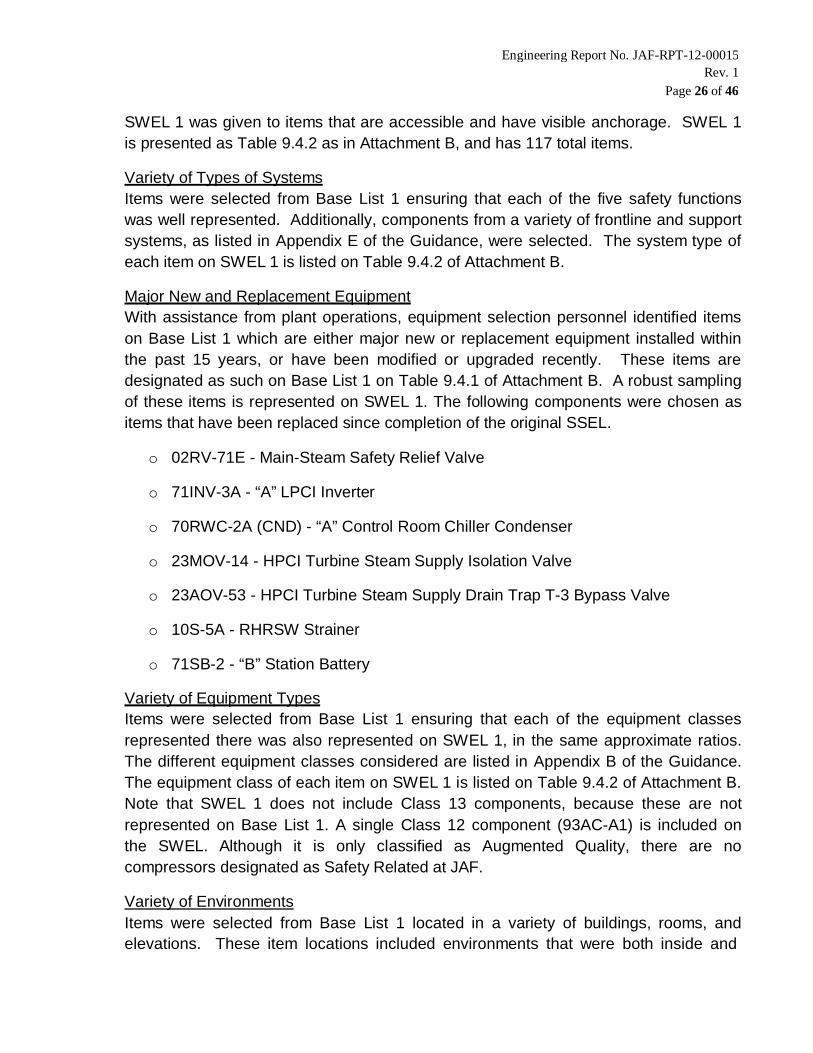
Page 26 of 46
SWEL 1 was given to items that are accessible and have visible anchorage. SWEL 1is presented as Table 9.4.2 as in Attachment B, and has 117 total items.
Variety of Types of SystemsItems were selected from Base List 1 ensuring that each of the five safety functionswas well represented. Additionally, components from a variety of frontline and supportsystems, as listed in Appendix E of the Guidance, were selected. The system type ofeach item on SWEL 1 is listed on Table 9.4.2 of Attachment B.
Major New and Replacement EquipmentWith assistance from plant operations, equipment selection personnel identified itemson Base List 1 which are either major new or replacement equipment installed withinthe past 15 years, or have been modified or upgraded recently. These items aredesignated as such on Base List 1 on Table 9.4.1 of Attachment B. A robust samplingof these items is represented on SWEL 1. The following components were chosen asitems that have been replaced since completion of the original SSEL.
o 02RV-71E - Main-Steam Safety Relief Valve
o 71INV-3A - “A” LPCI Inverter
o 70RWC-2A (CND) - “A” Control Room Chiller Condenser
o 23MOV-14 - HPCI Turbine Steam Supply Isolation Valve
o 23AOV-53 - HPCI Turbine Steam Supply Drain Trap T-3 Bypass Valve
o 10S-5A - RHRSW Strainer
o 71SB-2 - “B” Station Battery
Variety of Equipment TypesItems were selected from Base List 1 ensuring that each of the equipment classesrepresented there was also represented on SWEL 1, in the same approximate ratios.The different equipment classes considered are listed in Appendix B of the Guidance.The equipment class of each item on SWEL 1 is listed on Table 9.4.2 of Attachment B.Note that SWEL 1 does not include Class 13 components, because these are notrepresented on Base List 1. A single Class 12 component (93AC-A1) is included onthe SWEL. Although it is only classified as Augmented Quality, there are nocompressors designated as Safety Related at JAF.
Variety of EnvironmentsItems were selected from Base List 1 located in a variety of buildings, rooms, andelevations. These item locations included environments that were both inside and

Engineering Report No. JAF-RPT-12-00015Rev. 1
Page 27 of 46
outside, as well as having high temperature and/or elevated humidity. The location andenvironment of each item on SWEL 1 is listed on Table 9.4.2 of Attachment B.
IPEEE EnhancementsThe IPEEE does not include any specific vulnerabilities for components which couldbe considered for the SWEL 1 (see Section 5.0). However, the following componentswere chosen based on their “lower” seismic capabilities. Note that the bottom 3 listedcomponents are associated with seismic induced anchorage failure at groundaccelerations between 0.31g and 0.41g:
10E-2A “A” RHR Heat Exchanger
10S-5A “A” RHRSW Strainer
09-32 Channel “A” RHR/RCIC Relay Panel
71MCC-161 600V Motor Control Center (Bus 116100)
71DSC-11561 L15 Unit Substation Transformer T-13 High Side Disch SW
Risk SignificanceInformation from the plant Probabilistic Risk Assessment (PRA) model and theMaintenance Rule implementation documentation were used to determine whetheritems were risk significant. Risk significance was determined by using Risk ImportanceMeasures, Risk Achievement Worth (RAW), and Fussell-Vesely (FV). This risk wasconsidered using a threshold value of RAW 2 and FV 0.0001. Higher riskcomponents were given added consideration for selection as a SWEL 1 item.
6.2 SPENT FUEL POOL ITEMS
The overall process for developing a sample of SSCs associated with the spent fuel pool(SFP) is summarized in Figure 1-2 of the Guidance. The equipment coming out of Screen #2and entering Screen #3 is defined as Base List 2. The equipment coming out of Screen #4 isthe equipment that could potentially cause the SFP to drain rapidly. The equipment comingout of Screen #3 and Screen #4 is the second Seismic Walkdown Equipment List, or SWEL2. Development of these lists is described separately in the following sections.
6.2.1 Base List 2
Based on Figure 1-2 and Section 3 of the Guidance, Base List 2 represents theSeismic Category (SC) I equipment or systems associated with the SFP. To developBase List 2, Equipment Selection Personnel (see Section 4.1) reviewed plant designand licensing basis documentation and plant drawings for the SFP and its associatedcooling system. Base List 2 is presented as Table 9.4.3 in Attachment B, and has 13

Engineering Report No. JAF-RPT-12-00015Rev. 1
Page 28 of 46
total items. The following components were replaced in SWEL 2 and are not currentlyshown on the Base List.
o Decay Heat Removal Strainer Bypass Valve 32DHR-5 replaced with DecayHeat removal Cooling Water Return Isolation Valve 32DHR-18 because ofradiological considerations.
o Decay Heat Removal SFP Water Primary Pump A 32P-1A was removed fromthe list due to radiological reasons.
6.2.2 Rapid Drain-Down
Rapid drain-down is defined in EN-DC-168, Attachment 9.4 [Ref. 10.11], as loweringthe water level to the top of the fuel assemblies within 72 hours after an earthquake.Consistent with the Guidance, the Equipment Selection Personnel (see Section 4.1)identified SSCs that could cause the SFP to drain rapidly by first reviewing the SFPdocumentation to identify penetrations below about 10 ft above the top of the fuelassemblies.
Because this review found no such SFP penetrations, there is no potential for rapiddrain-down and no items were included on the rapid drain-down list to include onSWEL 2.
6.2.3 SWEL 2
Based on Figure 1-2 and Section 3 of the Guidance, SWEL 2 is a broad population ofitems on Base List 2 including representative items from some of the variations withineach of four sample selection attributes (using sample process similar to SWEL 1),plus each item that could potentially cause rapid-drain down of the SFP. Due to thepopulation of items on Base List 2 being much smaller than Base List 1, the samplingattributes are satisfied differently for SWEL 2 than for SWEL 1. The followingparagraphs describe how the equipment selected from Base List 2 for inclusion onSWEL 2 are representative with respect to each of the four sample selection attributes.SWEL 2 is presented as Table 9.4.5 in Attachment B, and has 11 total items. The SFPat JAF has no qualified rapid drain-down (RDD) components, as described in EN-DC-168, Attachment 9.4 [Ref. 10.11]; therefore no RDDs were included in SWEL 2 list.
Variety of Types of SystemsThere are 2 systems, Spent Fuel Cooling and Decay Heat Removal, associated withSFP. Each of these systems is represented on SWEL 2.

Engineering Report No. JAF-RPT-12-00015Rev. 1
Page 29 of 46
Major New and Replacement EquipmentNew and Replaced components are identified in Table 9.4.5, Column “N/R”. Out of 11SWEL 2 components, 9 were not replaced within 15 years; therefore considered to benew, and 2 components are newly installed.
Variety of Equipment TypesThere are 5 different equipment classes represented on Base List 2: 01, 05, 07, 20and 21. Each of these equipment classes is represented on SWEL 2.
Variety of Environments10 out of 11 SFP components noted on SWEL 2 are inside the Reactor Building andare thus located in similar environments. The remaining component is located outside.
6.3 DEFERRED, INACCESSIBLE ITEMS on SWEL
The intent of adding each item on the SWEL is for it to be walked down as part of the NTTF2.3 Seismic Walkdown program. To be able to perform the seismic walkdowns of theseitems, it is necessary to have access to them and to be able to view their anchorage. Insome cases, it was not feasible to gain access to the equipment or view its anchorage duringthe entire 180-day response period of Enclosure 3 to the 50.54(f) Letter. For these cases,walkdowns of these items have been deferred until the next refueling outage (RFO) inSeptember of 2014, or the items were deleted from the list. An updated submittal reportincorporating these deferred walkdowns will be provided 90 days after the end of RFO21.
The originally deferred and deleted items are summarized in the table below. The reasonis identified as either ACC (indicating that the item was deleted because of ALARA reasons)or CAB (indicating that the item required opening cabinet/panel doors which was notpermitted by plant Operations personnel during the i n i t i a l walkdowns in 2012, dueto being energized or otherwise). A total of 26 items are listed on the table below. Of thistotal, 23 items were previously deferred. The remaining 3 are in high dose areas and willnot be deferred. The 23 originally deferred items are cabinets/panels that were required to beopened.
SWEL# Equipment ID Description Location Reason
SWEL 1-163 12MOV-18
RWCU supply outbound isolation valve, islocated in a Locked High Radiation Area(LHRA). Dose levels are high, both inoutage and normal plant operation. Thisitem is deleted from the SWEL list becauseof dose concern and will not be deferred.
RB. EL 300’,Column 3, Line R
ACC

Engineering Report No. JAF-RPT-12-00015Rev. 1
Page 30 of 46
SWEL# Equipment ID Description Location Reason
SWEL 2-2 19FPC-32
The skimmer surge tank A condensatemake-up check valve, is located in a LHRAbehind the “A” Skimmer Surge Tank. Thisitem is deleted from the SWEL list becauseof dose concern and will not be deferred.
RB. EL 369.6’,Column 3.5, LineY
ACC
SWEL 2-11 32P-1A
The decay heat removal SFP waterprimary pump “A”, is located in a highradiological area. This item is deleted fromthe SWEL list because of dose concernand will not be deferred.
RB. 326’,Column 3, Line T
ACC
SWEL1-52 09-3
The nuclear station main control boardwas originally deferred. The open cabinetinspection walkdown has been completed.See Attachment J.
AD. 300’,Column 10, Line F
CAB
SWEL1-430 71-10502
The 4160V switchgear distribution (BUS10500) was originally deferred. Theopen cabinet inspection walkdown hasbeen completed. See Attachment J.
EG. 272’,Column 24, Line A1
CAB
SWEL1-433 71-10560
The 4160V switchgear distribution (BUS10500) was originally deferred. The opencabinet inspection walkdown has beencompleted. See Attachment J.
EG. 272’,Column 26, Line A1
CAB
SWEL1-438 71-11502
The 600V switchgear distribution (bus11500) breaker 02 was originallydeferred. The open cabinet inspectionwalkdown has been completed. SeeAttachment J.
RB. 300’,Column 26, Line A1
CAB
SWEL1-439 71-11602
The 4160V switchgear distribution (BUS10600) was originally deferred. Theopen cabinet inspection walkdown hasbeen completed. See Attachment J.
EG. 272’,Column 2, Line R
CAB
SWEL1-446 71BAT-3AThe LPCI inverter battery was originallydeferred. The open cabinet inspectionwalkdown has been completed. SeeAttachment J.
RB. 344.6’,Column5.5
CAB
SWEL1-448 71BC-1A
The 125 VDC station battery charger wasoriginally deferred. The open cabinetinspection walkdown has been completed.See Attachment J.
BR. 272,Column 12.5, Line E
CAB
SWEL1-450 71BCB-2AThe battery A control board was originallydeferred. The open cabinet inspectionwalkdown has been completed. SeeAttachment J.
BR. 272,Column 13, Line C
CAB

Engineering Report No. JAF-RPT-12-00015Rev. 1
Page 31 of 46
SWEL# Equipment ID Description Location Reason
SWEL1-462 71DSC-11561
The L15 unit substation transformer T-13high side discharge was originally deferred.The open cabinet inspection walkdown hasbeen completed. See Attachment J.
RB. 300’,Column 2, Line R
CAB
SWEL1-470 71INV-3A
The LPCI MOV independent power supplyA inverter was originally deferred. The opencabinet inspection walkdown has beencompleted. See Attachment J.
RB.344.6’,Column
CAB
SWEL1-474 71L25
The 600V switchgear distribution (BUS12500) was originally deferred. Theopen cabinet inspection walkdown hasbeen completed. See Attachment J.
EB. 272’,Column 18.5,Line A1
CAB
SWEL1-481 71MCC-161
The 600V motor control center (BUS116100) was originally deferred. Theopen cabinet inspection walkdown hasbeen completed. See Attachment J.
EB. 272’,Column 1.5, Line W
CAB
SWEL1-487 71MCC-252
The 600V motor control center (BUS125200) was originally deferred. The opencabinet inspection walkdown has beencompleted. See Attachment J.
EB. 272’,Column 18, Line A
CAB
SWEL1-489 71MCC-254
The 600V motor control center (BUS125400) was originally deferred. The opencabinet inspection walkdown has beencompleted. See Attachment J.
EB. 272’,Column 23, Line A1
CAB
SWEL1-624 93ECP-A
The EDG A engine control panel wasoriginally deferred. The open cabinetinspection walkdown has been completed.See Attachment J.
EG. 272’,Column24
CAB
SWEL1-628 93ECSP-AThe EDG A engine control sub panelwas originally deferred. The opencabinet inspection walkdown has beencompleted. See Attachment J.
EG. 272’,Column24
CAB
SWEL1-629 93ECSP-BThe EDG B engine control sub panelwas originally deferred. The opencabinet inspection walkdown has beencompleted. See Attachment J.
EG. 272’,Column 26, Line A3
CAB
SWEL1-636 93EGP-A
The EDG C generator control panel wasoriginally deferred. The open cabinetinspection walkdown has been completed.See Attachment J.
EG. 272’,Column 24, Line A1
CAB
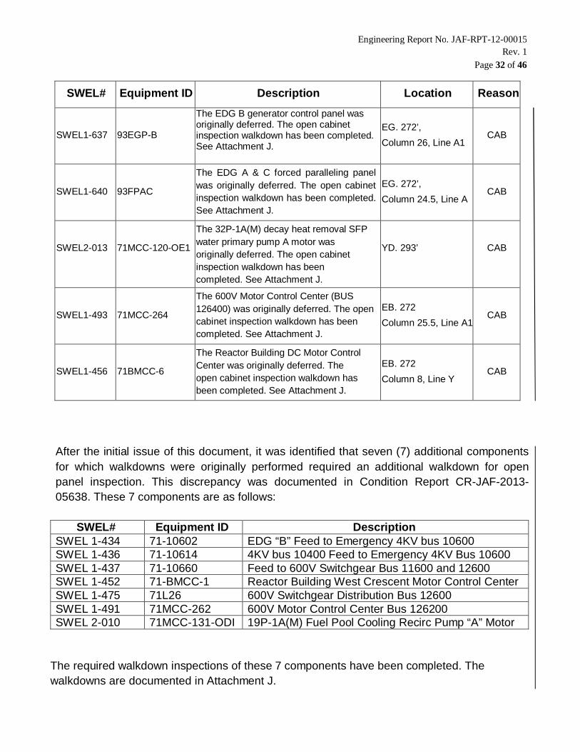
Engineering Report No. JAF-RPT-12-00015Rev. 1
Page 32 of 46
After the initial issue of this document, it was identified that seven (7) additional componentsfor which walkdowns were originally performed required an additional walkdown for openpanel inspection. This discrepancy was documented in Condition Report CR-JAF-2013-05638. These 7 components are as follows:
SWEL# Equipment ID DescriptionSWEL 1-434 71-10602 EDG “B” Feed to Emergency 4KV bus 10600SWEL 1-436 71-10614 4KV bus 10400 Feed to Emergency 4KV Bus 10600SWEL 1-437 71-10660 Feed to 600V Switchgear Bus 11600 and 12600SWEL 1-452 71-BMCC-1 Reactor Building West Crescent Motor Control CenterSWEL 1-475 71L26 600V Switchgear Distribution Bus 12600SWEL 1-491 71MCC-262 600V Motor Control Center Bus 126200SWEL 2-010 71MCC-131-ODI 19P-1A(M) Fuel Pool Cooling Recirc Pump “A” Motor
The required walkdown inspections of these 7 components have been completed. Thewalkdowns are documented in Attachment J.
SWEL# Equipment ID Description Location Reason
SWEL1-637 93EGP-B
The EDG B generator control panel wasoriginally deferred. The open cabinetinspection walkdown has been completed.See Attachment J.
EG. 272’,Column 26, Line A1
CAB
SWEL1-640 93FPAC
The EDG A & C forced paralleling panelwas originally deferred. The open cabinetinspection walkdown has been completed.See Attachment J.
EG. 272’,Column 24.5, Line A
CAB
SWEL2-013 71MCC-120-OE1
The 32P-1A(M) decay heat removal SFPwater primary pump A motor wasoriginally deferred. The open cabinetinspection walkdown has beencompleted. See Attachment J.
YD. 293’ CAB
SWEL1-493 71MCC-264
The 600V Motor Control Center (BUS126400) was originally deferred. The opencabinet inspection walkdown has beencompleted. See Attachment J.
EB. 272Column 25.5, Line A1
CAB
SWEL1-456 71BMCC-6
The Reactor Building DC Motor ControlCenter was originally deferred. Theopen cabinet inspection walkdown hasbeen completed. See Attachment J.
EB. 272Column 8, Line Y
CAB

Engineering Report No. JAF-RPT-12-00015Rev. 1
Page 33 of 46
7.0 SEISMIC WALKDOWNS AND AREA WALK-BYS
The NTTF 2.3 Seismic Walkdown program conducted in accordance with the Guidanceinvolves two primary walkdown activities, Seismic Walkdowns and Area Walk-Bys. Theseactivities were conducted at JAF, by teams of two trained and qualified SWEs (see Section4.2). JAF in-house Civil Engineers performed a portion of the 2 0 1 2 walkdowns. BothSWEs on these teams have several years of seismic experience. For the balance of the 2012walkdowns (Performed by contractors), each team (2 teams total) included one engineer withat least several years of experience in seismic design and qualification of nuclear power plantSSCs, whereas the second engineer had somewhat less (though sufficient) experience. Incertain instances, the teams (both JAF and contractors) periodically “shuffled” personnel tocross- check consistency between the two teams. All of the deferred walkdowns wereperformed by JAF in-house Civil Engineers and an Entergy shared resource Civil Engineer.
The initial seismic walkdowns and area walk-bys were conducted over a span ofapproximately 6 weeks, starting in mid-September of 2012. The deferred walkdowns wereperformed during JAF Operating Cycle 21 and completed in Refuel Outage 21. Pre-job briefswere performed prior to walkdowns. This pre-job brief was used to outline the componentsand areas that would be walked down, to ensure consistency between the teams, toreinforce expectations and process for identifying potentially adverse seismic conditions(and other non-seismic plant conditions), and to allow team members to ask questions andshare feedback.
7.1 SEISMIC WALKDOWNS
Seismic walkdowns were performed in accordance with Section 4 of the Guidance for allitems on the SWEL (SWEL 1 plus SWEL 2), except for those few (total of 3) determined tobe inaccessible due to their location in a high dose area (see Section 6.3). To document theresults of the walkdown, a Seismic Walkdown Checklist (SWC) with the same content as thatincluded in Appendix C of the Guidance was created for each item. Additionally, photographswere taken of each item and included on the corresponding SWC.
In some cases, the SWE teams conducted preliminary “scouting” walkdowns to get a generalunderstanding of plant layout and to identify items on the draft SWEL that were in a too highdose area. Items that were identified to be inaccessible on these “scouting” walkdowns werediscussed with the Equipment Selection Personnel and were either deleted or deferred (untilafter startup from Refuel Outage 20) while ensuring that the overall integrity of the final SWELwas not compromised.
Prior to performance of the walkdowns, documentation packages were developed thatcontained the SWC with preliminary data entered and other pertinent information includingthe location drawings, response spectra information, previous IPEEE seismic walkdowndocumentation, and anchorage drawings where applicable. These documentation packagesaccompanied the SWE teams into the plant during the seismic walkdowns.
Engineering Report No. JAF-RPT-12-00015Rev. 1
Page 34 of 46
Walkdown inspections focused on anchorages and seismic spatial interactions, but alsoincluded inspections for other potentially adverse seismic conditions. Anchorage, in all cases,was considered to specifically mean anchorage of the component to the structure whereapplicable. This included anchor bolts to concrete walls or floors, structural bolts to structuralsteel and welds to structural steel or embedded plates. For welds, the walkdown team lookedfor cracks and corrosion in the weld and base metal. Other bolts or connections, such asflange bolts on in-line components were not considered as equipment anchorage. Thesebolts and connections were evaluated by the SWEs and any potential adverse seismicconcerns were documented under “other adverse seismic conditions” rather than under“anchorage”. Thus, components with no attachments to the structure are considered as nothaving anchorage. Nevertheless, the attachment of these components to other equipmentwas evaluated and inspected for potentially adverse seismic conditions.
Cabinets/panels on the SWEL that could be reasonably opened without undue safety oroperational hazard were opened during the initial 2012 walkdown. This allowed visualobservation of internal anchorage to the structure (where present), as well as inspection for“other adverse seismic conditions” related to internal components that could be observedwithout breaking the plane of the door. Where opening the cabinet/panel was considered toexhibit undue safety or operational hazards, it was considered inaccessible and thecompletion of the walkdown of that item was deferred to a later time (see Section 6.3).Where opening the cabinet/panel required extensive disassembly (e.g., doors or panels weresecured by more than latches, thumbscrews, or similar), justification for how the inspectionmet the program goal without opening the cabinet/panel was included on the SWC and thewalkdown of that item is considered complete.
In addition to the general inspection requirements, at least 50% of the SWEL items havinganchorage required confirmation that the anchorage configuration was consistent with plantdocumentation. Of the 128 SWEL items, 81 were considered to have anchorage (i.e.,removing in-line/line-mounted components). Of these 81 anchored components, thewalkdowns of 54, not counting deferred components (See Section 6.3), included anchorageconfiguration verification, which is greater than 50%. When anchorage configurationverification was conducted, the specific plant documentation used for comparison to the as-found conditions was referenced on the SWC.
The SWC for each SWEL item, where a seismic walkdown has been initiated is included inAttachment C. A total of 128 SWCs are attached, 105 with completion status marked “Y”(“Y”- Yes, Walkdown is completed), 0 with completion status marked “N” (“N”- No, Walkdownhas not been performed), and 23 with completion status marked “U” (“U”- Uncertain, Moreinformation on the component is required). SWCs considered and marked “Uncertain”, arethose where a walkdown was initiated, but whose completion was ultimately deferredbecause the cabinet/panel could not be opened during the initial 2012 walkdowns.Therefore, the 105 completed SWCs represent the completed walkdowns of the 128 SWELitems accessible during the 2012 walkdown timeframe.

Engineering Report No. JAF-RPT-12-00015Rev. 1
Page 35 of 46The 23 originally deferred component walkdows identified as “Completion Status-Uncertain”along with the 7 additional component walkdowns identified by CR-JAF-2013-05638 werecompleted in JAF Operating cycle 21 and Refuel Outage 21. These walkdowns aredocumented in Attachment J with a status of “Y” indicating all walkdowns are completed.
7.2 AREA WALK-BYS
Seismic area walk-bys were performed in accordance with Section 4 of the Guidance for allplant areas containing items on the SWEL (SWEL 1 plus SWEL 2). Area walk-bys were notdeferred where components were deferred simply to open cabinets/panels. A separate AreaWalk-By Checklist (AWC) with the same content as that included in Appendix C of theGuidance was used to document the results of each area walk-by performed. Photographswere taken of each area, and included on the corresponding SWC.
Area walk-bys were conducted once for plant areas containing multiple SWEL items in closeproximity to each other. In cases where the room or area containing a component was verylarge, the extent of the area encompassed by the area walk-by was limited to a radius ofapproximately 35ft around the subject equipment. In some cases, the extent of the areasincluded in the area walk-bys is described on the AWC for that area. Because certain areascontained more than one SWEL item, there are fewer total area walk-bys conducted thanseismic walkdowns. A total of 61 area walk-bys was necessary to cover all plant areascontaining at least one SWEL item.
The AWC for each area walk-by completed is included in Attachment D. A total of 61 AWCsare attached, which represent all of the areas containing a SWEL item that were accessibleduring the walkdown period. No additional area walk-bys of areas need to be performed,since walk-bys for the deferred items have been completed (see Section 6.3).
Engineering Report No. JAF-RPT-12-00015Rev. 1
Page 36 of 46
8.0 LICENSING BASIS EVALUATIONS
During the course of the seismic walkdowns and area walk-bys, SWE teams sought toidentify existing degraded, non-conforming, or unanalyzed plant conditions with respect to itscurrent seismic licensing basis identify. This section summarizes the process used to handleconditions identified, what conditions were found, and how they were treated for eventualresolution.
CONDITON IDENTIFICATION
When a potentially adverse condition was observed by a SWE team in the field, the conditionwas noted on the SWC or AWC form and briefly discussed between the two SWEs todetermine whether it was a potentially adverse seismic condition. These initial conclusionswere based on conservative engineering judgment and the training required for SWEqualification.
For conditions that were reasonably judged as insignificant to seismic response, thedisposition was included on the SWC or AWC checklist and the appropriate question wasmarked “Y”, indicating that no associated potentially adverse seismic condition was observed.Unusual or uncertain conditions were reported to site personnel for further resolution (seeSection 8.2). A total of 17 seismically insignificant conditions were identified in the originalwalkdown scope. These conditions were generally related to either housekeeping or milddegradation.
For conditions that were judged as potentially significant to seismic response, then thecondition was photographed and the appropriate question on the SWC or AWC was marked“N” indicating that a potentially adverse seismic condition was observed. The condition wasthen immediately reported to site personnel for further resolution and was documented forreporting in Attachment E. A total of 17 potentially adverse seismic conditions wereidentified in the original walkdowns performed in 2012. These conditions were generallyrelated to non-conforming anchorage, spatial interaction, non-conforming support spacing, orinadequate line flexibility.
The deferred walkdown scope resulted in 17 additional potentially adverse seismic conditionswhich were added to Attachment E. In almost all cases, these issues were related to theopen panel inspection and the majority of the deficiencies were missing fasteners on sub-components.
CONDITION RESOLUTION
Conditions observed during the seismic walkdowns and area walk-bys determined to bepotentially adverse seismic conditions are summarized in Attachment E, including how eachcondition has been addressed and its current status.

Engineering Report No. JAF-RPT-12-00015Rev. 1
Page 37 of 46Each potentially adverse seismic condition is addressed either with a Licensing BasisEvaluation (LBE) to determine whether it requires entry into the Corrective Action Program(CAP), or by entering it into the CAP directly. The decision to conduct a LBE or enterthe condition directly into the CAP was made on a case-by-case basis, based on theperceived efficiency of each process for eventual resolution of each specific condition.
Unusual conditions that were not seismically significant were immediately brought to attentionto plant personnel. Further resolution of these conditions is not tracked or reported as part ofthe NTTF 2.3 Seismic Walkdown program, except by noting that the condition was observedby SWE and it was immediately brought to attention to plant personnel on the applicableSWCs and AWCs.
8.1 LICENSING BASIS EVALUATIONS
Potentially adverse seismic conditions identified as part of the NTTF 2.3 Seismic Walkdownprogram may be evaluated by comparison to the current licensing basis (CLB) of the plant asit relates to the seismic adequacy of the equipment in question, as is described in Section 5of the Guidance. If the identified condition is consistent with existing seismic documentationassociated with that item, then no further action is required. If the identified condition cannoteasily be shown to be consistent with existing seismic documentation, or no seismicdocumentation exists, then the condition is entered into the CAP.
Of the 17 identified potentially adverse seismic conditions identified in Rev. 0 of this report, 14did not require a LBE. All items summarized in Attachment E, are entered into the CAP orjustification of their acceptability is provided in Attachment F. An additional LBE was addedresulting from the deferred walkdown scope.
8.2 CORRECTIVE ACTION PROGRAM ENTRIES
Conditions identified during the seismic walkdowns and area walk-bys that required furtherresolution were entered into the plant’s Corrective Action Program (CAP) for further reviewand disposition in accordance with the plant’s existing processes and procedures. Conditionsentered into the CAP included three types of unusual conditions identified:
Seismically insignificant unusual conditionsPotentially adverse seismic condition that does not pass a LBEPotentially adverse seismic condition that bypasses a LBE
A total of 32 Condition Reports (CRs) were generated from the CAP as a result of the NTTF2.3 Seismic Walkdown program. Of this total, 17 CRs were generated from the deferredwalkdown scope. All 32 of the CRs were written relative to potentially adverse seismicconditions identified. The CR numbers, current status, and resolution (where applicable andavailable) are summarized for these potentially adverse seismic conditions in Attachment E.

Engineering Report No. JAF-RPT-12-00015Rev. 1
Page 38 of 46
8.3 PLANT CHANGES
The CAP entries (CRs) generated by the NTTF 2.3 Seismic Walkdown program are beingresolved in accordance with the plant CAP process, including operability evaluations, extentof condition evaluations, and root cause analysis (where applicable). Initial evaluations fromRev. 0 of this report indicated that no immediate plant changes are necessary. Based onfinal and complete resolutions of the CRs generated from the walkdowns, one modificationto the plant was required. This modification is documented in EC 42623 and is associatedwith the addition of a supplementary support to an existing High Pressure Coolant Injection(HPCI) conduit support frame (Ref. CR-JAF-2012-07990).
As a result of the seismic walkdowns and walk-bys, the requirement for a plant modificationas well as the need for a variety of repairs were identified (such as the replacement ofmissing fasteners on subcomponents) as well as housekeeping issues. Current status andresolutions (where applicable and available) for CRs related to potentially adverse seismicconditions are provided in Attachment E.
Engineering Report No. JAF-RPT-12-00015Rev. 1
Page 39 of 46
9.0 PEER REVIEW
9.1 PEER REVIEW PROCESS
The peer review for the Near Term Task Force (NTTF) Recommendation 2.3 SeismicWalkdowns was performed in accordance with and in conformance to Section 6 of theGuidance. The peer review included an evaluation of the following activities:
review of the selection of the structures, systems, and components, (SSCs) thatare included in the Seismic Walkdown Equipment List (SWEL);
review of a sample of the checklists prepared for the Seismic Walkdowns andarea walk-bys
review of licensing basis evaluations and decisions for entering the potentiallyadverse conditions in to the plant’s Corrective Action Plan (CAP); and
review of the final submittal report.
At least two members of the peer review team (see Section 4.5) were involved in the peerreview of each activity, the team member with the most relevant knowledge and experiencetaking the lead for that particular activity. A designated overall Peer Review Team Leaderprovided oversight related to the process and technical aspects of the peer review, payingspecial attention to the interface between peer review activities involving different members ofthe peer review team.
The peer review team was provided with an early draft of this submittal report for peer review.The peer review team verified that the submittal report met the objectives and requirementsof Enclosure 3 to the 50.54(f) Letter, and documented the NTTF 2.3 Seismic Walkdownprogram performed in accordance with the EPRI Guidance. The peer review team providedthe results of review activities to the SWE team for consideration. The SWE teamsatisfactorily addressed all peer review comments in the final version of the submittal report.The signature of the Peer Review Team Leader provides documentation that all elements ofthe peer review as described in Section 6 of the EPRI Guidance were completed.
9.2 PEER REVIEW RESULTS SUMMARY
The following sections summarize the process and results of each peer review activity.
9.2.1 Seismic Walkdown Equipment List Development
The selection of items for the SWEL was peer reviewed in accordance with Section 3of the EPRI Guidance. Peer review comments were resolved and incorporated into thefinal SWEL, ensuring that all recommendations of the EPRI Guidance have been met.
Engineering Report No. JAF-RPT-12-00015Rev. 1
Page 40 of 46
The final SWEL contains a diverse sample of equipment required to perform the fivesafety functions specified in the EPRI Guidance, which are:
Reactor reactivity control
Reactor coolant pressure control
Reactor coolant inventory control
Decay heat removal
Containment integrity
In addition, the peer review process verified that SWEL items included major new andreplacement items, a variety of environments, equipment enhanced based on findingsof the IPEEE (if any), and risk insight considerations.
The peer review checklist of the SWEL is provided in Attachment G.
9.2.2 Seismic Walkdowns and Area Walk-Bys
Peer review of the seismic walkdowns and area walk-bys was conducted by two peerreviewers, each of whom is a qualified SWE and has broad knowledge of seismicengineering applied to nuclear power plants. One of the peer reviewers participated inthe seismic walkdown program for a different utility, and the other is engaged with theindustry team which developed the Guidance (see Section 4.5). The peer reviewswere conducted at JAF concurrent with the conduct of walkdowns, at approximately50% completion. The peer review was performed as follows:
The peer review team reviewed the walkdown packages (including checklists,photos, drawings, etc.) for SWEL items already completed to ensure that thechecklists were completed in accordance with the Guidance. A total of 23 SWCand 16 AWC forms were reviewed, each representing approximately 18% and26%, respectively, of their totals. In the context of the Guidance, the peer reviewteam considered the number of walkdown packages reviewed to be appropriate.The packages reviewed represent a variety of equipment types in various plantareas. Specific SWC forms reviewed are SWEL1-001, 032, 052, 069, 137, 157,213, 433, 448, 452, 457, 474, 494, 501, 519, 624, 646, 670, 683, 686, 690,SWEL2-007 and SWEL2-009. Specific AWC forms reviewed are AWC-003, 006,009, 013, 015, 017, 018, 021, 022, 029, 033, 034, 045, 047, 049, and 057. Duringthe selection of SWC’s and AWC’s to be peer reviewed, particular attention wasgiven to obtaining a broad sample of items that encompass a variety of equipmentand systems, equipment classes and environmental conditions.

Engineering Report No. JAF-RPT-12-00015Rev. 1
Page 41 of 46
While reviewing the walkdown packages, the peer reviewers conducted informalinterviews of the SWEs and asked clarifying questions to verify that they wereconducting walkdowns and area walk-bys in accordance with the Guidance.
The peer review team held a meeting with the SWE teams to provide feedback onthe walkdown and walk-by packages reviewed and the informal interviews, anddiscuss potential modifications to the documentation packages in the context of theGuidance.
The peer review team held a meeting with the SWE teams to provide feedback onthe walkdown and walk-by observations, and discuss how lessons learned fromreview of the walkdown packages had been incorporated into the walkdownprocess.
As a result of the peer review activities, the SWE teams modified their documentationprocess to include additional clarifying details, particularly related to checklistquestions marked “N/A” and where conditions were observed but judged asinsignificant. The peer review team felt these modifications would be of benefit forfuture reviews of checklists incorporated into the final report. These modificationswere recommended following review of the walkdown and area walk-by packages, andthe o b s e r v a t i o n walkdowns and area walk-bys demonstrated that theSWEs understood the recommendations and were incorporating them into thewalkdown and area walk-by process. Previously completed checklists were revised toreflect lessons learned from the peer review process.
Based on completion of the walkdown and walk-by peer review activities described,the peer review team concludes that the SWE teams are familiar with and followed theprocess for conducting seismic walkdowns and area walk-bys in accordance with theGuidance. The SWE teams adequately demonstrated their ability to identify potentiallyadverse seismic conditions such as adverse anchorage, adverse spatial interaction,and other adverse conditions related to anchorage, and perform anchorageconfiguration verifications, where applicable. The SWEs also demonstrated the abilityto identify seismically-induced flooding interactions and seismically-induced fireinteractions such as the examples described in Section 4 of the Guidance. The SWEsdemonstrated appropriate use of self-checks and peer checks. They discussed theirobservations with a questioning attitude, and documented the results of the seismicwalkdowns and area walk-bys on appropriate checklists.
Engineering Report No. JAF-RPT-12-00015Rev. 1
Page 42 of 469.2.3 Licensing Basis Evaluations
All potentially adverse seismic conditions were entered into the plant’s CAP programfor further review and disposition. See Attachment E for summary of CRs and LBevaluations. The review team verified the decisions for identifying such conditions asbeing sound, and the dispositions were conducted in accordance with the plant’s CLB.
A peer review of the licensing basis evaluations was completed. Within theselicensing basis evaluations, CRs were generated for maintenance issues to replacemissing bolts, nuts or remove items for housekeeping issues, or to provide further,detailed resolution of the potentially adverse seismic condition when applicable. Theremaining licensing basis evaluations were created to document potentially adverseseismic conditions that were immediately entered into the CAP for detailed evaluationand investigation. See Attachment F for detailed LB evaluations. The peer review ofthese LB evaluations ensured that all the information provided from the walkdownteam to the licensing basis evaluation team member provided enough detail foraccurate and timely resolution. See Attachment I for comments received on LBevaluations.
9.2.4 Submittal Report
The peer review team was provided with an early draft of this submittal report for peerreview. The peer review team verified that the submittal report met the objectives andrequirements of Enclosure 3 to the 50.54(f) Letter, and documented the NTTF 2.3Seismic Walkdown program performed in accordance with the Guidance. The peerreview team provided the results of review activities to the SWE team forconsideration. The SWE team satisfactorily addressed all peer review comments in thefinal version of the submittal report. The signature of the Peer Review Team Leaderprovides documentation that all elements of the peer review as described in Section 6of the Guidance were completed.
Engineering Report No. JAF-RPT-12-00015Rev. 1
Page 43 of 46
9.3 PEER REVIEW RESULTS SUMMARY – DEFERRED SCOPE ACTIVITIES
This section addressed the peer review effort associated with the Fukushima NTTF 2.3Seismic Walkdown activities that were deferred due to plant accessibility restrictionsduring the initial walkdown phase performed in 2012. All of the deferred scope seismicwalkdowns and area walk-bys were completed as of the end of JAF Refueling OutageRFO 21 in October 2014.
The deferred scope specifically included: Seismic Walkdown Checklists (30 SWEL items) Licensing Basis Evaluation (1 issue evaluated) Development of Revision 1 of the submittal report
There were no changes that affected the IPEEE Vulnerabilities Evaluations and nochanges to the equipment originally selected for inspection (SWEL). Therefore, noadditional peer review associated with these two topics is required.
Seismic Waldown ChecklistsPeer Review of the SWCs was performed by Bill Grabowski of JAF (bio in Section 4.0).Mr. Grabowski is a qualified Seismic Walkdown Engineer who did not participate in theinitial scope plant walkdowns at JAF but was involved in a portion of the JAF deferredscope walkdowns. Review comments were incorporated into the SWCs as appropriate(see Attachment I).
Licensing Basis Evaluation (LBE)Peer review of the one new Licensing Basis Evaluation was performed by Robert Kesterof JAF (bio in Section 4.0).
Submittal Report Revision 1Bill Grabowski performed the peer review for Revision 1 of the submittal report. Theresulting miscellaneous editorial and formatting comments have been incorporated intothe final product as appropriate (see Attachment I).
Summary of Overall Effectiveness of Peer Review EffortThe peer review effort for the deferred scope activities did not identify any significantprocess-type weaknesses. This was to be expected given that this involved acontinuation of an established program that had been refined via lessons learned at JAF,the Entergy fleet during the initial (much larger) phase of the project, and the industry.The peer review comments tended to be editorial in nature and/or related to effectivelyincorporating the new information into the existing report structure. The peer review effortis considered to have been effective in ensuring that the standards and expectationsestablished during the initial project phase were maintained and ultimately resulted in ahigh quality and well integrated final submittal report.

Engineering Report No. JAF-RPT-12-00015Rev. 1
Page 44 of 46
10.0 REFERENCES
10.1. 10CFR50.54(f) Letter, Request for Information Pursuant to Title 10 of the Codeof Federal Regulations 50.54(f) Regarding Recommendations 2.1, 2.3 and 9.3of the Near-Term Task Force Review of Insights from the Fukushima Dai-IchiAccident, dated March 12, 2012
10.2. EPRI 1025286, Seismic Walkdown Guidance for Resolution of FukushimaNear-Term Task Force Recommendation 2.3: Seismic, June 2012
10.3. James A. FitzPatrick Nuclear Power Plant Updated Final Safety AnalysisReport (UFSAR)
10.4. Generic Letter No. 88-20, Supplement 4 and 5, Individual Plant Examination ofExternal Events (IPEEE) for Severe Accident Vulnerabilities
10.5. James A. Fitzpatrick Nuclear Power Plant Individual Plant Examination ofExternal Events (IPEEE), JAF-RPT-MISC-02211, Revision 0, Submitted June1996.
10.6. Generic Letter No. 87-03, Verification of Seismic Adequacy of Mechanical andElectrical Equipment in Operating Reactors, Unresolved Safety Issue (USI) A-46
10.7. Seismic Qualification Utility Group (SQUG) Procedure: Generic ImplementationProcedure (GIP) for Seismic Verification of Nuclear Power Plant Equipment,Revision 3A, December 2001
10.8. JAF Document 18570.00, Rev. 1, “Design Criteria for Balance of Plant (BOP)Piping Stress and Supports – James A. FitzPatrick Nuclear Power Plant.”
10.9. Engineering Standard Manual: CES-2B, Rev. 0, “Seismic Design of ElectricalConduit Supports for JAF.”
10.10. JAF-RPT-ELEC-02075, Rev. 2, “Design Criteria for Independence ofRedundant Electrical Circuits.”
10.11. EN-DC-168, Rev. 0, “Fukushima Near-Term Task Force Recommendation 2.3Seismic Walk-down Procedure.”
10.12. JAFP-12-0075, “Entergy’s 120-Day Response to the NRC Request forInformation (RFI) Pursuant to 10CFR50.54(f) Regarding the Seismic Aspects ofRecommendation 2.3 of the Near Term Task Force Review of Insights from theFukushima Dai-ichi Accident.”
Engineering Report No. JAF-RPT-12-00015Rev. 1
Page 45 of 46
10.13. USI A-46, “Seismic Evaluation Report Volume I/VI, Stevenson & Associates,”September 1995.
10.14. James A. FitzPatrick Nuclear Power Plant, Safe Shutdown Equipment andRelay Evaluation For unresolved Safety Issue USI A-46,” September 1995,Volume I of XII.

Engineering Report No. JAF-RPT-12-00015Rev. 1
Page 46 of 46
11.0 ATTACHMENTS
ATTACHMENT A – IPEEE VULNERABILTIES TABLE
ATTACHMENT B – SEISMIC WALKDOWN EQUIPMENT LISTS
ATTACHMENT C – SEISMIC WALKDOWN CHECKLISTS (SWCs)
ATTACHMENT D – AREA WALK-BY CHECKLISTS (AWCs)
ATTACHMENT E – POTENTIALLY ADVERSE SEISMIC CONDITIONS
ATTACHMENT F – LICENSING BASIS EVALUATION FORMS
ATTACHMENT G – PEER REVIEW CHECKLIST FOR SWEL
ATTACHMENT H – SEISMIC WALKDOWN ENGINEER TRAINING CERTIFICATES
ATTACHMENT I – PEER REVIEW COMMENTS
ATTACHMENT J – DEFERRED SEISMIC WALKDOWN CHECKLISTS (SWC’S)