Embed Size (px)
Citation preview
ATTENUATORS UP TO 1.5GHz Sam Wetterlin
5/16/08
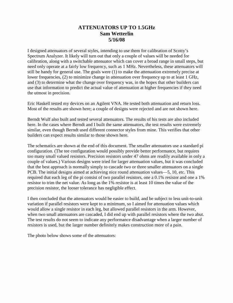
I designed attenuators of several styles, intending to use them for calibration of Scotty’s Spectrum Analyzer. It likely will turn out that only a couple of values will be needed for calibration, along with a switchable attenuator which can cover a broad range in small steps, but need only operate at a fairly low frequency, such as 1 MHz. Nevertheless, these attenuators will still be handy for general use. The goals were (1) to make the attenuation extremely precise at lower frequencies, (2) to minimize change in attenuation over frequency up to at least 1 GHz, and (3) to determine what the change over frequency was, in the hopes that other builders can use that information to predict the actual value of attenuation at higher frequencies if they need the utmost in precision. Eric Haskell tested my devices on an Agilent VNA. He tested both attenuation and return loss. Most of the results are shown here; a couple of designs were rejected and are not shown here. Berndt Wulf also built and tested several attenuators. The results of his tests are also included here. In the cases where Berndt and I built the same attenuators, the test results were extremely similar, even though Berndt used different connector styles from mine. This verifies that other builders can expect results similar to those shown here. The schematics are shown at the end of this document. The smaller attenuators use a standard pi configuration. (The tee configuration would possibly provide better performance, but requires too many small valued resistors. Precision resistors under 47 ohms are readily available in only a couple of values.) Various designs were tried for larger attenuation values, but it was concluded that the best approach is normally simply to cascade two or three smaller attenuators on a single PCB. The initial designs aimed at achieving nice round attenuation values—5, 10, etc. This required that each leg of the pi consist of two parallel resistors, one a 0.1% resistor and one a 1% resistor to trim the net value. As long as the 1% resistor is at least 10 times the value of the precision resistor, the looser tolerance has negligible effect. I then concluded that the attenuators would be easier to build, and be subject to less unit-to-unit variation if parallel resistors were kept to a minimum, so I aimed for attenuation values which would allow a single resistor in each leg, but allowed parallel resistors in the arm. However, when two small attenuators are cascaded, I did end up with parallel resistors where the two abut. The test results do not seem to indicate any performance disadvantage when a larger number of resistors is used, but the larger number definitely makes construction more of a pain. The photo below shows some of the attenuators:
Some Assembled Attenuators
The male and female connectors were different types, the male being designed for panel mounting and the female for PCB mounting. Using connectors with similar shapes on both ends would make construction easier. The attenuators are constructed with a single PCB about 0.35” wide and 0.75” to 1.25” long. Male and female SMA connectors are slid on to the ends. End launch styles are perfect, but upright PCB mount styles will also fit well. For male connectors, I used a two-hole panel mount style, but alignment of that style is more difficult. Once assembled, the attenuators are encased by soldering brass strips across the top and bottom. This provides a bit of mechanical stability. They are then wrapped with copper tape, and sealed with ½” heat-shrink tubing. The brass reinforcing strips need be only 1/16” thick for the shortest attenuators. For longer ones, I soldered a second strip to the first, but made the second shorter so the ends of the combined strip were only 1/16” thick. This made soldering the strip to the connectors easier without having to blast them with a lot of heat. A 1/32” strip could have been used for the second strip. (The idea of the second not extending the full length comes from truss designs for flat-roof buildings, which sometimes have just a single strip of iron running the full length, with the truss work starting a foot from the wall. It works great.) For the longer attenuators, rather than using a brass strip across the bottom, I directly soldered a small brass angle (open side down) to the bottom of the PCB, again extending not quite the full length of the board. It makes a very rigid support, though it puts a minor bump in the bottom of the finished attenuator. Berndt Wulf tested attenuators with and without shields. There was no change in attenuation up to 1.5 GHz. In one case the phase delay increased 2% with the shield; in the other it decreased 1%. Return loss was mildly affected. This indicates that the shield mainly provides mechanical stability and isolation from the outside world, and that different methods of shield construction will not have any material impact on performance. The results of the tests were very encouraging. Attenuation value and return loss are nearly ideal at lower frequencies. Return loss was generally better than 40 db up to 500 MHz, and in only one case got worse than 30 db by 1.5 GHz. The attenuation values held virtually constant up to 500 MHz, and by 1 GHz change by anywhere from zero to 0.15 db. The largest value attenuator, 47.4 db, showed a more marked decline in attenuation at high frequency, suggesting that the level of direct leakage from input to output starts to become noticeable at that level of attenuation.
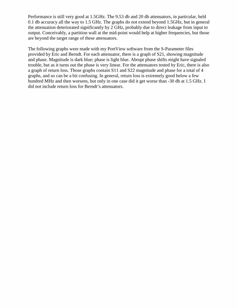
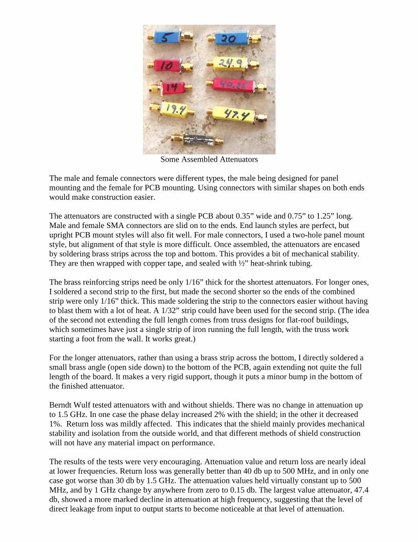
Performance is still very good at 1.5GHz. The 9.53 db and 20 db attenuators, in particular, held 0.1 db accuracy all the way to 1.5 GHz. The graphs do not extend beyond 1.5GHz, but in general the attenuation deteriorated significantly by 2 GHz, probably due to direct leakage from input to output. Conceivably, a partition wall at the mid-point would help at higher frequencies, but those are beyond the target range of these attenuators. The following graphs were made with my PortView software from the S-Parameter files provided by Eric and Berndt. For each attenuator, there is a graph of S21, showing magnitude and phase. Magnitude is dark blue; phase is light blue. Abrupt phase shifts might have signaled trouble, but as it turns out the phase is very linear. For the attenuators tested by Eric, there is also a graph of return loss. Those graphs contain S11 and S22 magnitude and phase for a total of 4 graphs, and so can be a bit confusing. In general, return loss is extremely good below a few hundred MHz and then worsens, but only in one case did it get worse than -30 db at 1.5 GHz. I did not include return loss for Berndt’s attenuators.
5 db Attenuation
5.00 db Return Loss
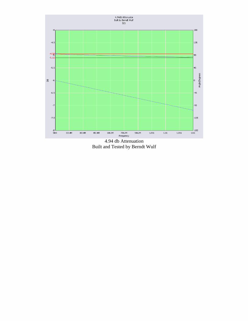
4.94 db Attenuation
Built and Tested by Berndt Wulf
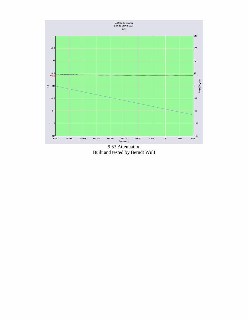
9.53 Attenuation
Built and tested by Berndt Wulf
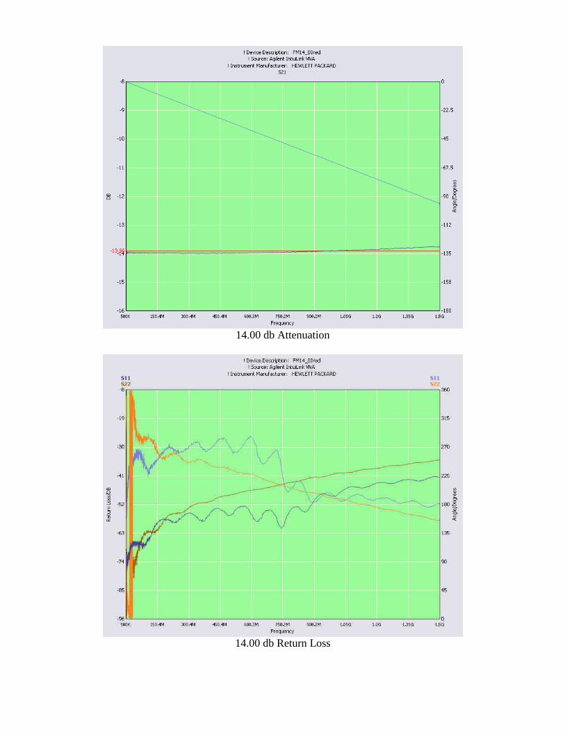
14.00 db Attenuation
14.00 db Return Loss
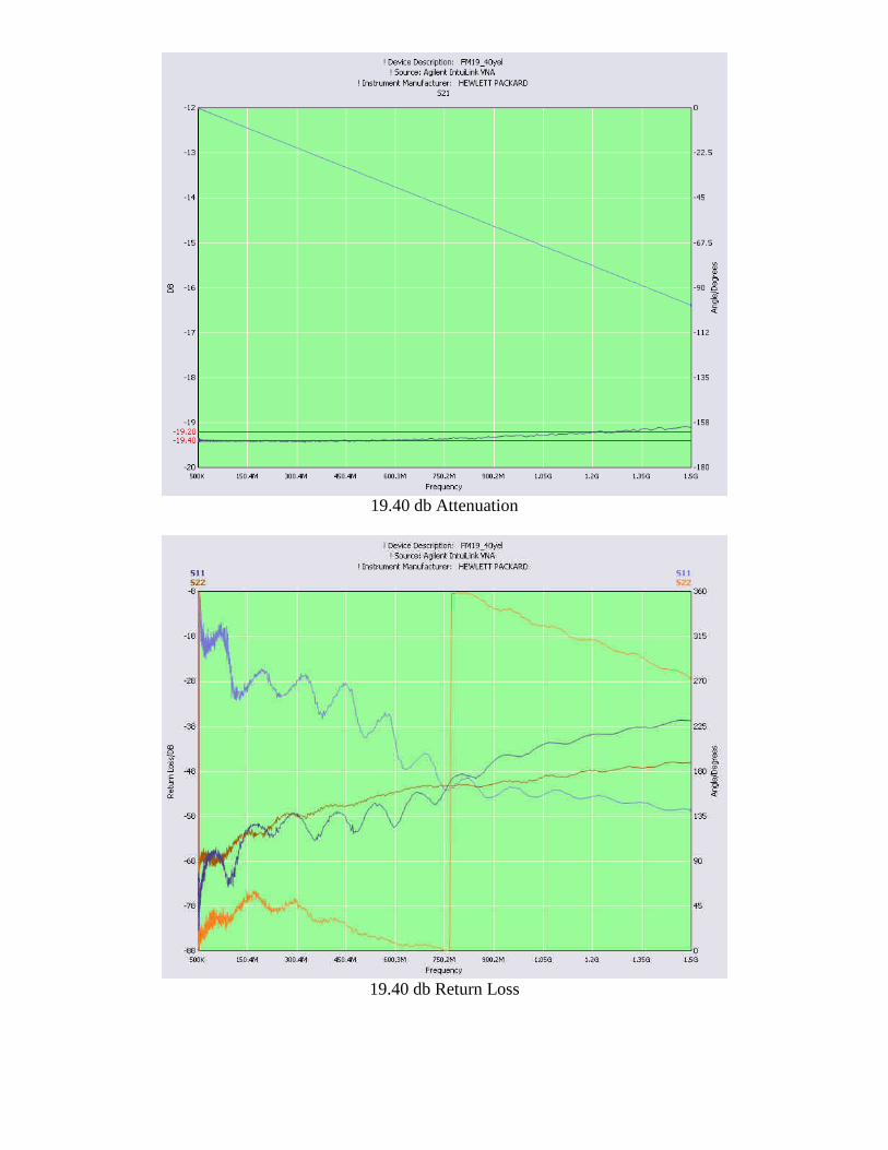
19.40 db Attenuation
19.40 db Return Loss
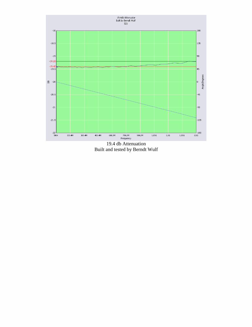
19.4 db Attenuation
Built and tested by Berndt Wulf
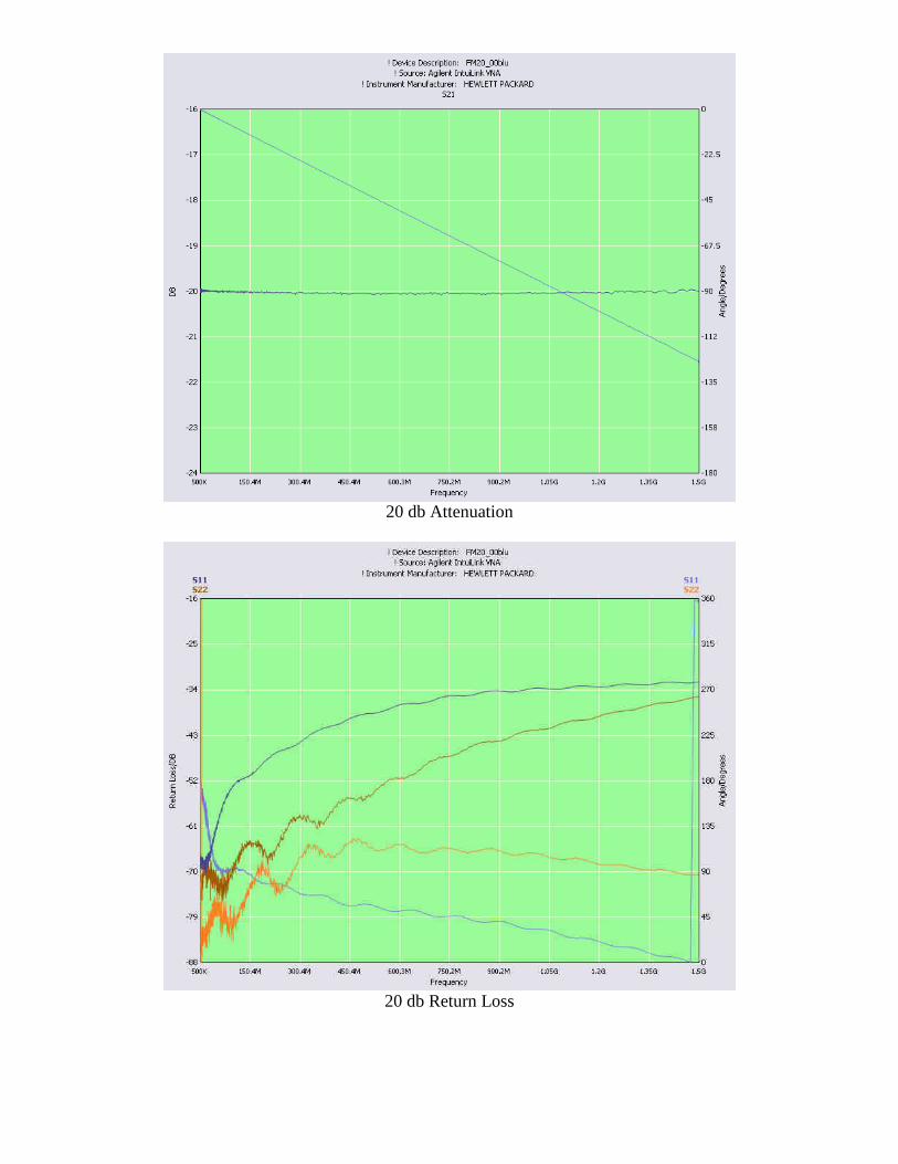
20 db Attenuation
20 db Return Loss
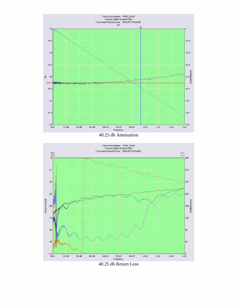
40.25 db Attenuation
40.25 db Return Loss
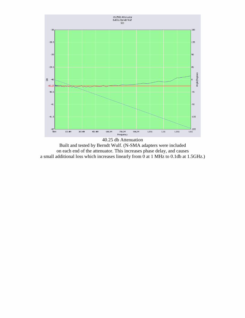
40.25 db Attenuation
Built and tested by Berndt Wulf. (N-SMA adapters were included on each end of the attenuator. This increases phase delay, and causes
a small additional loss which increases linearly from 0 at 1 MHz to 0.1db at 1.5GHz.)
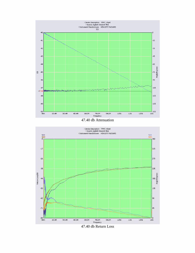
47.40 db Attenuation
47.40 db Return Loss
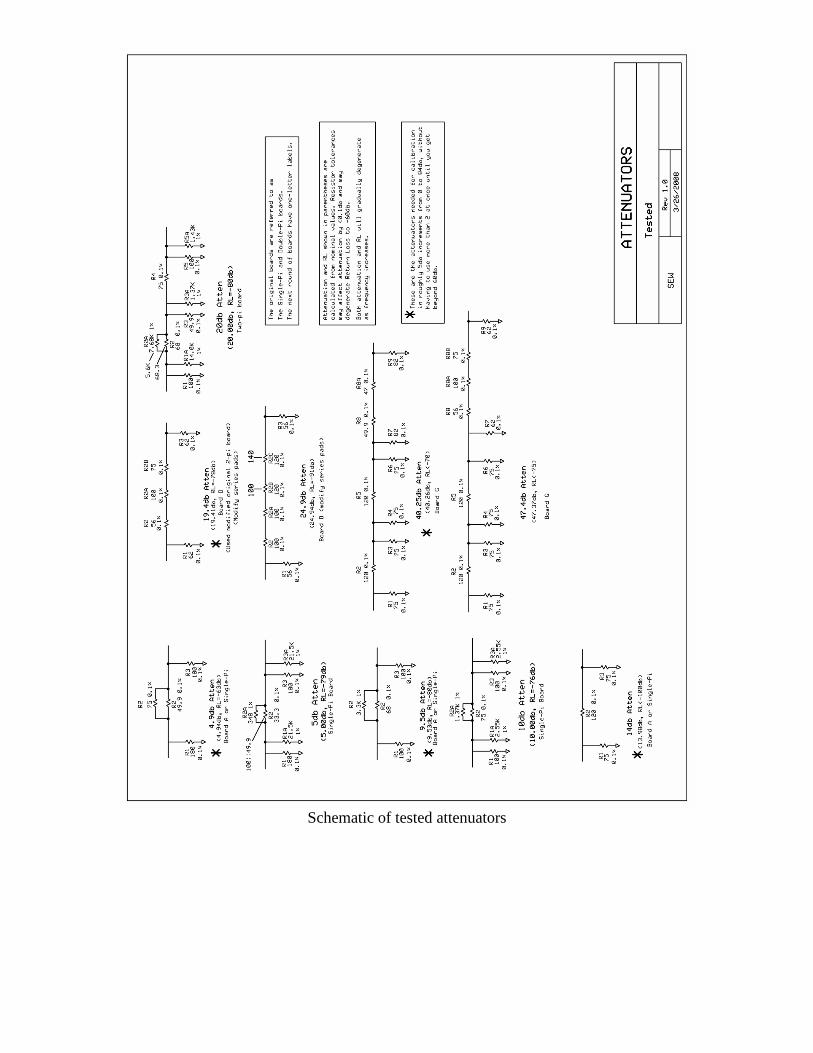
Schematic of tested attenuators