Embed Size (px)
Citation preview
3
1. IntroductionThis Mulitmeter is equipped with several special features and useful fun-ctions which are indispensable for electrical and electronic measure-ment: back-light, illuminates display in poor lighting conditions duringmeasurement, or the quadro-display, a multiple display with four simul-taneous reading outputs e.g. during “POWER“ measurement display ofreal power input, current input of the consumer, AC voltage and powerfactor (Cos Phi).
AUTO RANGE always selects the correct measuring range, to archievebest accuracy. The function REL allows the operator to measure valuewith respect to a preset reference value, in the secondary displays theOffset is shown, the deviation in ± % and the preset reference value andthe main display shows the present measuring value. With the functionCMP, comparative measurement can be made, the upper and the lowerlimit can be defined. With the function MEM (for Memory = store) andRCL (for Recall), 10 measurements can be stored in memory and recalled. AUTO-POWER-CUT-OFF extends the life of the battery by turning off themeter (Stand-by) if neither the rotary function switch nor a button isoperated for 12 minutes.
The DMM can be used for hobby, industry (with restrictions) and school.etc.
2. Safety Rules• The multimeter M-3860M is EMC-tested and corresponds to the fol-
lowing EG-standard: 89/336/EWG
• This unit is constructed and checked according to DIN 57 411Part 1/VDE 0411 Part 1, Safety Requirement for Electronic MeasuringUnits. This unit left the factory in safe and perfect condition. To main-tain the unit in this condition and to guarantee a safe operation, theuser must observe the safety rules and warnings which are containedin this manual, by all means.
• This multimeter may only be used in fuse lines which are protectedwith 16 A. The voltage existing/appearing must not exceed 250 VDC/VAC and the maximum load must not exceed 4000 VA. It is not allo-wed to use the unit for installations in the overload range III according
2
Digital-Multimeter M 3860-MOrder No.: 12 39 00
The proper operation of the measuring unit includes:
• measurement of DC voltage up to 1000 VDC max. • measurement of AC voltage up to 750 VAC. • measurement of DC and AC current to 20 A (fused)• measurement of resistance to 40 MΩ max.• measurement of capacitance of 400 µF• continuity check, diode and transistor test, logic test• measurement of frequency to 40 MHz max.• measurement of temperatures from -40 °C to +1200°C max.• CMOS-signal output to 10.24 KHz in 10 steps• it is not allowed to operate the unit in wet or damp environment!• any other usage as described above is forbidden
Attention! Read before Operation!Read this manual carefully and completely. In the case of damage cau-sed by non-observance of the instruction, the claims under guaranteelapse. No legal liability can be accepted for any damage from the multi-meter being used for the wrong purpose or operated improperly. Wecannot take any liability for consequential damage.
ContentsPage
1. Introduction . . . . . . . . . . . . . . . . . . . . . . . . . . . . . . . . . . . . . . . . . . . 3
2. Safety Rules . . . . . . . . . . . . . . . . . . . . . . . . . . . . . . . . . . . . . . . . . . . 3
3. Description of the Control Elements . . . . . . . . . . . . . . . . . . . . . . . . 6
4. Usage of the Multimeter . . . . . . . . . . . . . . . . . . . . . . . . . . . . . . . . . 9
5. Measurement . . . . . . . . . . . . . . . . . . . . . . . . . . . . . . . . . . . . . . . . . 20
6. Maintenance and Calibration . . . . . . . . . . . . . . . . . . . . . . . . . . . . . 38
7. Technical Data and Accuracy . . . . . . . . . . . . . . . . . . . . . . . . . . . . . 39
GB
5
Such voltage might cause a life-dangerous electrical shock when elec-trical conductors are touched.First switch off voltage source, connect the measuring unit with theterminals of the voltage source to be measured, set the measuringunit to the necessary voltage range and afterwards switch on voltagesource.After measurement has been finished, switch off the voltage sourceand remove the measuring cables from the terminals of the voltagesource.
• Make sure before each voltage measurement the unit is not set to theamperage range.
• Before changing the measuring range remove the probe tips from theobject to be measured.
• Control before each measurement the measuring unit and your testleads to make sure they are not damaged.
• Do not use this measuring unit in environments or rooms with adver-se environmental conditions where flammable gases, steams or dustsexist or may exist. For your own safety avoid under all circumstancesthat the measuring unit or the test leads become damp or wet.
Avoid the usage near
a) strong magnetic fields (loudspeakers, magnets)
b) electromagnetic fields (transformers, motors, coils, relays, contac-tors, electromagnets etc. )
c) electrostatic fields (charge/discharge).
d) transmission antennas or hf-generators
• For measurement use only those test leads which are supplied withthe measuring unit. Only these are admissible.
• To avoid an electrical shock, don’t touch directly or indirectly the testprobes and the test points during measurement.
• To avoid serious electrical shock and/or instrument damage do notapply more than 500 VDC/VACrms between any terminal of the mea-suring unit and the earth ground.
4
to IEC 664. The unit and the measuring cables are not protectedagainst arcing (IEC 1010-2-031, section 13.101).
• Keep children away from measuring units!
• Pay attention to the rules for prevention of accidents in industrialenterprises prescibed by the Industrial Trade Associations for ElectricalInstallations and Production Facilities.
• When using the unit in schools and hobby-workshops the usage andthe measurement has to be controlled by the responsible teachers orskilled personell.
• If covers are opened or parts are removed, except it is possible with-out tools, voltage-carrying components may be accessable. Terminalscan also carry voltage. If it is necessary to open the unit before adjust-ment, maintenance, repairing or exchange of parts or modules, themeasuring unit has to be separated from all voltage sources and mea-suring circuits. Repairs or maintenance to the measuring unit mustonly be carried out by qualified service personell or qualified electrici-ans who know the dangers and the respective rules (VDE 0100, VDE-0701, VDE-0683).
• Capacitors in the unit can still carry voltage, even if the unit has beenseparated from all voltage sources.
• Please make sure to use new fuses of the proper rating. Do not userepaired fuses and do not bridge the fuse holders.To replace the fuse separate the measuring unit from the measuringcircuit, remove any input signal and switch it off. Remove all connec-ted cables and probe tips. Use a suitable crosspoint screw drivercarefully open the case. Remove the defective fuse(s) and replace itwith a new one of the same type and nominal current 0.8 A quick blow,250 V; usual name: F 0.8 A/250 V or F 800 mA/250V. For the amperagerange 20 A ultra rapid, 250 V; usual name: FF 20 A/250 V (BUSS ABC20).After the fuse has been exchanged close the cabinet. Do not operatethe unit before it has been closed and screwed safely.
• Use special caution when working with voltage above 25 V (AC) andabove 35 V (DC).
7
6. DOWN ButtonThis key is needed in the manual range mode to select the next lowerrange.
7. Display Back LightPress button short and several small LEDs illuminate the display-background, it is sufficient to read display even in poor lighting conditions.
8. Transistor SocketThis socket is for testing the hfe-parameter of different semiconduc-tors (except power transistors and FETs, triacs and thyristors).
9. Capacitance and Temperature & Signal Output, Input SocketThis socket is for testing discharged! capacitors or temperatures.
10. Rotary Function Switch to select the different modes (voltage andcurrent measurement, etc.)
11. 20-A Input SocketThis input socket is designed for measuring DC and AC current tomax. 20 A and is fused with 20 A.
12. mA-inputThis socket is for measuring DC and AC current to 400 mA max.
13. COM-Input Socket (COM or Minus Terminal)
14. V-Ohm-(+) Input Socket (Plus Terminal)
15. Liquid Crystal Display (LCD) (3 3/4 digit, max. display value 4000)
16. Analogous Bargraph
17. Bargraph-Segments
Figure see folding page
18. Overload “OL“-Indication“OL“ is displayed and an acoustic signal is emitted when the range isexceeded = overflow (no acoustic signal during resistance measure-ment, diode test or temperature measurement).
6
• If there are doubts whether a safe usage is still possible the unit hasto be put out of operation and be secured against unintentional use.
It must be assumed that a safe usage is not possible if
- the unit shows visible damage
- the unit does not work and
- longterm storage under unfavourable conditions
or
- transport strain took place
• Don’t switch on the measuring unit immediately after bringing it infrom a cold to warm room. Condensed water might impair or destroyyour unit. Give the unit time to warm up to room temperature with-out switching it on.
3. Description of the Operation Elements
Picture see folding page
1. Power ON/OFF
2. Push Button for FunctionWith this key you can set the different sub-function as, MIN/MAX,REL, CMP etc.
3. Set/Reset Button “SET/R“With this key the unit is reset, the selected function mode is exited.In certain function modes the Reset function does not work!
4. DC OHM /AC Push ButtonPress this button to toggle between DC and AC when function switchis set to voltage or current, or when function switch is set to resi-stance to change between resistance measurement to (acoustic) con-tinuity check.
5. UP ButtonThe key is needed in the manual range mode to select the nexthigher range.
9
33. CAP = CapacitanceCAP is for Capacitance => Measurement of capacitors
34. hFEThis symbol indicates the transistor test.
35. LOGI = Logic TestThis symbol indicates the Logic Test Function
36. 1. 2. and 3. Sub-Display These three small sub-displays with 3 3/4 digits are activated duringthe different function modes.
37. = Low Battery When this symbol is displayed, it is time to change the battery
38. Different Units of the Display Values
4. Usage of the Multimeter4.1 Inserting the Battery - Battery ExchangeTo guarantee precise measurement, insert a standard 9 V battery. If thebattery symbol appears in the display, it is time to change the battery.Proceed as follows:
• Disconnect your measuring unit from the measuring circuit, disconnectthe test-leads from the measuring unit and turn off the power. Remove with a crosspoint screw driver the fastening screw to open thebattery compartment. Now lift the cover carefully (use a small screwdriver). Separate the old battery from the battery snap and fasten a new oneof the same type. Do not forget to use the provided battery insulationcapsule.
After the battery has been changed reinsert the battery into the bat-tery case and close it carefully, secure it with the screw.
+ -
8
Attention!Observe the max. input limits.
19. Data Hold D-HData Hold means the meter will “freeze“ a display reading.
20. REL = Relative = Reference Value
21. CMP = Comparison = Compare a Reading
22. R-H = Range Hold= Holding the current preset measuring range e.g. 40 KOhm
23. A-H = Auto Hold= Min-, Max- and AVG-holding with simultaneous display
24. MEM = Memory= to memorize the value
25. RCL= Recall= to get back the memorized reading on the display.
26. Reference No. (0 to 9)
27. = Diode Test
28. AC = Symbol for AC current or voltage
29. = Symbol for Acoustic Continuity Check
30. “ - “ = Minus Sign or Symbol for Negative Polarity
31. FREQ = FrequencyThis symbol is displayed in the Frequency Count Mode
32. TEMP = TemperatureThis symbol is displayed during temperature measurement.
11
4.4 Operation
4.4.1 Basic Settings
Hint!The numbers which are put in brackets in the following text refer to“Description of the Operation Elements“, point 3.
Press the button “ON“ (1). Turn the rotary function switch to the desiredposition. Now the meter is ready for “normal“ operation without addi-tional function. Even without additional functions “small“ displays (sub-displays) support measurement.
To select an additional function press the key FUNCTION (2). Press itagain to scroll through the different sub-functions.
To exit the menu press SET/R-key twice: press SET/R-key once to enter,press button twice to exit/reset (depending on the preset sub-function).
4.4.2 Terminal and Switch Imprint
a) Press the ON/OFF-key (1) to turn the unit on and off: Press the keyonce to turn the power on, press it again to turn the DMM off.AUTO-POWER-CUT-OFF extends the life of the battery: if neither therotary function switch nor a button is operated for 12 minutes theDMM is automatically turned off. During “communication“ of themultimeter with a PC, i.e exchange of data, AUTO-POWER-OFF is dis-abled.
b) FUNCPress this button to select the function modes. The following symbolsappear in the display when you scroll in the function modes:D-H -> R-H -> A-H -> REL -> MEM -> RCL -> CMP
c) SET/RPress this button once to activate or to enter the selected functionmode.
• Press in the function mode the button D-H again to exit (wait forbeeper sound).
10
Attention!Never use the measuring unit before the cover has been closed comple-tely, to avoid an electrical shock!
Never leave empty batteries in the measuring unit, as even corrosion-free batteries might leak and chemicals could be released, which aredetrimental to your health and disturb the battery compartment.Please remember batteries - due to their heavy metal content - are noordinary refuse. They must be disposed of in special containers or in asafe manner that complies with all applicable laws.
4.2 Connection of the Measuring CablesFor measurement use only the type of test-leads which are supplied withyour measuring unit. Only these are admissible. Ensure the connectionplugs and test probes are in good condition before usage, pay attentionthat the insulation is undamaged.
These test-leads are rated for max. 1200 V. The maximum rating of themultimeter M-3860M is 1000 VDC max or 750 VACrms. Use special cauti-on when working with voltage above 25 V AC and above 35 V DC.
Attention!To avoid the risk of electrical shock, instrument damage and/or equip-ment damage, input limits must not be exceeded.
4.3 Using the StandYour meter has a stand on the rear side for bench use which can beopend away from the meter. You can prop the unit for improvement ofreading.
13
sistor socket as in the drawing according to transistor type, removevoltage before measurement.
b) Capacity- and Temperature Measuring Socket (poles “+“ and “-“)In this socket discharged capacitors can be checked, observe correctpolarity. Make sure the connector pins are long enough to avoidunreliable measurement. For temperature measurement plug in type “K“ temp probes (NiCrNi),observe the correct polarity. Plug in adapter for function „SIG OUT“.
Attention!The outer contacts are only for capacitance measurement, the innercontacts are only! for temperature measurement & signal outputchecking. Never confuse the sockets to avoid damage of the meter.
c) Rotary Function Switch = Measuring Function Switch (10)
Attention!Never turn the rotary function switch during measurement, as there isthe risk of instrument damage and danger to life.
The different basic measuring ranges are selectable by turning the switch(clockwise).
SIG OUT = CMOS signal output - no function mode possible
mV = millivolt AC/DC (milli = 10 exp. -3) no manual range selction
V = Volt AC/DC - Auto-Range and manual range selection (R-H)is possible
FREQ = frequency measurement - Auto Range and manual rangeselection (R-H) is possible
12
• In the function mode R-H simply press button again to exit.
• In the function mode A-H (MIN-MAX and AVG) the R-H symbol (formanual range setting) and the A-H symbol is displayed. After thefirst push of the SET/R key the A-H symbol is set and will stop blin-king. The R-H-symbol continues flashing to be able to set themanual measuring range with buttons UP and DOWN. If the SET/R-key is pressed again, the R-H symbol is fixed. You can commencemeasurement. Another (third) push of the SET/R key discards thefunction and the previous normal mode is restored.
• In the function modes REL, MEM, RCL and CMP, push SET/R buttonseveral times to return to normal mode.
Another possibility to exit from these modes is either to press thebutton FUNC, DC/AC or ON/OFF once or to move the rotary functionswitch to an adjacent position (observe all safety rules!).
d) DC Ohm/AC ( )Press this button to toggle between DC and AC when the rotary fun-ction switch is set to resistance measurement, continuity check, to vol-tage or current or to switch from resistance measurement to acousticcontinuity check.
e) UP/DOWNPress UP or Down button to determine the reference value in the fun-ction modes REL or CMP or to address the stored value in the modesMEM or RCL (reference numbers). In the function mode R-H (= RangeHold) you can set manually the measuring range with these buttons.
f) Back LightTo switch on/off the back light (the back light is LED operated to saveenergy) push the yellow button. After 15 s the back light will auto-matically extinguish.
4.4.3 Terminal and Switch Imprint
a) Transistor Socket hfeThe eight pole transistor terminal is lettered symmetrically with (E)Emitter, (B) Base, (C) Collector. Insert the transistor pins into the tran-
15
f) COM = Common Input TerminalFor all measurements, except capacity, temperature and transistormeasurement, the Black test-lead must be connected. (common-ter-minal means minus or “-“ or earthing jack)
g) V/Ohm-SocketFor measurement of voltage, frequency, resistance, continuity, diodesand logic tests plug in the Red test-lead in this terminal.
h) For power measurement insert in all sockets the measuring adapter.
4.4.4 Display Explanation and Symbols
a) Digital Display Digital readings are displayed the main- and the sub-displays (smalldisplays) on a 4000-count basis (“3999“) with automatic polarity indic-tion (-) (for negative voltage or reversed polarity). There are threedecimal point positions.
b) Analogous BargraphThe bargraph consists of 43 segments and is faster than the digitaldisplay. It functions as the needle of an analogous measuring instru-ment, but without its mechanical disadvantages. Is is especially forquick changing measuring signals, for which the digital display is too“slow“. So you can quickly see tendencies in the measuring values. If the measuring range is exceeded “OL“ for Overload is displayed thebargraph is flashing and a warning sound is emitted (no acoustic sig-nal during measurement of resistance, diode, temperature - “OL“without thermo-element).
c) Data-Hold “D-H“In this mode you can freeze a reading in the second (“small“) displayby pressing the SET/R button.
d) Range Hold “R-H“In this function you can switch off the automatic range selection(Auto Range) and set the measuring range manually. Each time theUP or DOWN button is pressed the decimal point is moved one posi-tion to the left or to the right, the units of measure are changed res-pectively (e.g. from kHz to MHz during frequency measurement). To
14
LOGIC = Logic Test - no function mode possible
/Ohm = acoustic continuity test - no Auto-Range during continuitytest, in the resistance measuring range Auto-Range andmanual range selction (R-H) is possible
= diode test - no R-H possible
CAP = capacitance measurement, A-R and R-H is possible
hFE = transistor test - no R-H possible
TEMP = temperature measurement in °C - no R-H possible
4 mA = DC and AC current measurement to max. 4 mA - A-R and R-H possible
400 mA = DC and AC current measurement to max. 400 mA - A-R andR-H possible
20 A = DC and AC current measurement to max. 20 A - A-R andR-H possible
POWER = power measurement in [W] = Watt = unit for real power
d) 20-A-Input SocketFor DC- and AC-current measurements to max. ! 20 A. Insert the Redtest-lead into the input socket.
Attention !During current measurement the rotary function switch must not be setto voltage measurement (mV or V or other positions than 4 mA, 400 mA,20 A).
e) mA-Measuring SocketFor measurements to 400 mA max.!, connect the Red test-lead, payattention that the rotary function switch is set to position “4 mA“ or“400 mA“.
17
display will show the difference in %, the middle sub-display willshow the offset and the right sub-display the preset reference.
g) MEM (= Memory)Up to 10 measurements (reference number 0 to 9) can be stored andrecalled.
Proceed as follows:
1. Push function button until MEM flashes in the display, afterwardspress the key SET/R once. MEM is fixed and the reference numberflashes. Make your measurements and push the SET/R key once tostore the present measurement value in the first free memory loca-tion = reference no. 0.
2. Press UP/DOWN button to go to the next free memory location(reference no. between 0 and 9).Make again your measurement and push the key SET/R once. Theselected memory now is addressed. If a memory no. which has beenused before is selcted the previous value is updated and stored withthe new measurement value. The memorized value appears on themiddle sub-display. To exit this function mode turn the functionswitch (observe the safety rules!) or press the buttons FUNC or SET/R.
Hint! If you exit the function mode because you pushed the SET/R button toooften, this function mode is left but the memory is not erased and canbe “recalled“ with the following function mode.
h) RCL (= Recall)This function enables you to get the memorized reading back on theLCD.
Follow these steps:
Push FUNC key until RCL flashes. Push SET/R once. RCL is fixed but thereference number flashes. Press UP or DOWN buttons to address thedesired number where the measurement has been memorized. PressSET/R button to get the memorized value back on the display. Therecalled value (ref. no. 0) will appear on the left sub-display, 2nd
16
return from this function mode, press Set/Reset key twice (RESET) andyou will return to Auto Range.
e) Auto Hold A-HIn this function the meter will automatically record the minimum andthe maximum display reading, MIN and MAX values. These values arecurrently updated = refreshed. The MIN-value is shown on the leftsub-display, the MAX-value on the right sub-display. On the middlesub-display the average value = AVG is shown. This value is currently“refreshed“. Press FUNC key until A-H flashes in this function mode.Press once SET/R button. The symbol A-H is fixed, now the R-H (RangeHold) symbol flashes. Now push the UP and DOWN key to select therange for MIN, MAX and AVG measurement (e.g. for car voltage con-trol the 40 V-DC range = decimal point in the middle). If you fixed therange, press SET/R once again, the R-H sysmbol stops flashing. Bothsymbols are visible in the top line of the display. You can start measu-rement.
To exit this function mode press SET/R again or press FUNC or turn therotary function switch (observe the safety rules!), afterwards return tonormal settings.
f) REL (= Relative)The relative mode enables the operator to compare the referencevalue with a subsequent reading.
Proceed as follows:
• Set the function key at REL mode and press once the button SET/R
• Store the polarity by pressing the UP and DOWN keys, afterwardspress SET/R button.
• Press UP and DOWN buttons again to set the reference value youdesire and the decimal point (measuring range = R-H = Range-Hold). Press UP / Down buttons and SET/R by turns to move to thenext digit.
• For final setting of the reference value press SET/R button once.
The meter will now display the difference between the stored refe-rence value and the subsequent readings on the sub-displays, whilethe present (true) measurement is on the main-display. The left sub-
19
acoustic or visual test (display of measurement) is possible. An acou-stic signal is emitted at resistors below 40 Ohm.
c) Negative PolarityShows if test-leads are confused or indicates negative input with a “-“before the measurement.
d) FREQ Frequency MeasurementYou can measure frequency up to 40 MHz.
e) TEMP Temperature MeasurementYou can measure temperatures from -40°C to +1200°C with a ther-moelement (NiCrNi).
f) CAP Capacitance MeasurementThe capacitance range lets you measure discharged capacitors of 4 nFto 400 µF.
g) HFE Transistor TestEnables you to measure the hFE value.
h) LOGIC LogictestThis function enables you to check and to display all usual logic levels.
i) Low Battery A 9-Volt alkaline battery in this meter has an average life of approx.20 to 30 hours. Low battery indication appears approx. 8 hours befo-re battery is “dead“.
j) The following symbols indicate the units of the value displays:
AC = AC current or voltageDC = DC current or voltagemV = Millivolt (exp.-3)V = VoltsmA = Milliampere (exp.-3)A = AmpereW = WattkWh = Kilowatt hoursHz = HertzKHz = Kilohertz (exp.3)MHz = Megahertz (exp.6)
+ -
18
recalled value (ref. no. 1) on the middle sub-display and 3rd recalledvalue (ref. no. 2) on the right sub-display.
i) CMP (= Comparison)This function mode enables you to make the High/Low comparison ofsubsequent readings, by comparing a reading with both the storedhigh reference value and the stored low reference value.
On the sub-display “Lo“ appears for reading less than the low refe-rence value, “Hi“ is displayed for reading more than the highest refe-rence value and “Pass“ for a middle value between the low and thehigh reference value.To activate this function mode, push “Func“ until the symbol “CMP“appears on the top of the display and “LOW“ flashes over the leftsub-display. Now push again SET/R button and then “UP“ and“DOWN“ to set the minimum reference value with polarity. Pressafter each change SET/R button again, to enter the setting and to goto the next digit. As soon as the minimum reference (MIN) value hasbeen fixed, “HIGH“ flashes over the right sub-display. Set this highreference value respectively (with polarity and four digit value). Afterthe reference values have been defined press SET/R key again. Now“R-H“ for Range Hold flashes in the top line of the display. Set withthe UP and DOWN buttons the measuring range (e.g. voltage controlin a circuit under worst-case conditions). After the measuring rangehas been entered (as far as a manual selection is possible) Comparison= CMP is activated.
To exit CMP mode turn the rotary function switch (observe the safetyrules!) to an adjacent range or press “FUNC“.Reset with the SET/R button is also possible, even during measurement.
4.4.5 Display Annunciators and Symbols for the Modes
a) Diode Test The value displayed is the forward voltage at approx. 1 mA test cur-rent. Range of 0 - 2.0 V.
b) Continuity Check Enables you to check continuity of wiring, connections or fuses. Either
21
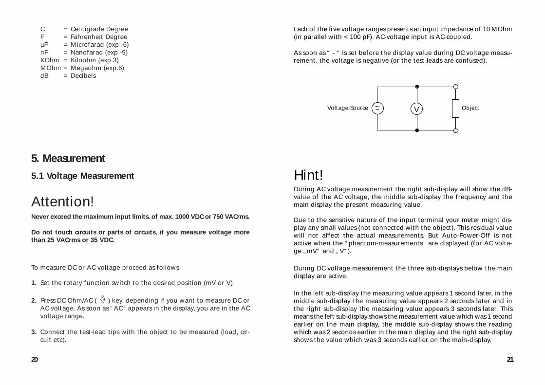
Each of the five voltage ranges presents an input impedance of 10 MOhm(in parallel with < 100 pF). AC-voltage input is AC-coupled.
As soon as “ - “ is set before the display value during DC voltage measu-rement, the voltage is negative (or the test leads are confused).
Hint!During AC voltage measurement the right sub-display will show the dB-value of the AC voltage, the middle sub-display the frequency and themain display the present measuring value.
Due to the sensitive nature of the input terminal your meter might dis-play any small values (not connected with the object). This residual valuewill not affect the actual measurements. But Auto-Power-Off is notactive when the “phantom-measurements“ are displayed (for AC volta-ge „mV“ and „V“).
During DC voltage measurement the three sub-displays below the maindisplay are active.
In the left sub-display the measuring value appears 1 second later, in themiddle sub-display the measuring value appears 2 seconds later and inthe right sub-display the measuring value appears 3 seconds later. Thismeans the left sub-display shows the measurement value which was 1 secondearlier on the main display, the middle sub-display shows the readingwhich was 2 seconds earlier in the main display and the right sub-displayshows the value which was 3 seconds earlier on the main-display.
~ VVoltage Source Object
20
C = Centigrade DegreeF = Fahrenheit DegreeµF = Microfarad (exp.-6)nF = Nanofarad (exp.-9)KOhm = Kiloohm (exp.3)MOhm = Megaohm (exp.6)dB = Decibels
5. Measurement5.1 Voltage Measurement
Attention!Never exceed the maximum input limits. of max. 1000 VDC or 750 VACrms.
Do not touch circuits or parts of circuits, if you measure voltage morethan 25 VACrms or 35 VDC.
To measure DC or AC voltage proceed as follows
1. Set the rotary function switch to the desired position (mV or V)
2. Press DC Ohm/AC ( ) key, depending if you want to measure DC orAC voltage. As soon as “AC“ appears in the display, you are in the ACvoltage range.
3. Connect the test-lead tips with the object to be measured (load, cir-cuit etc).
23
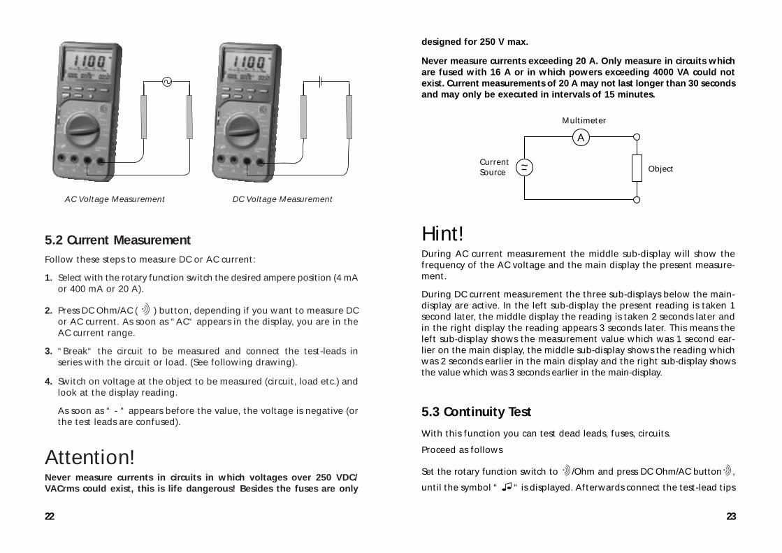
designed for 250 V max.
Never measure currents exceeding 20 A. Only measure in circuits whichare fused with 16 A or in which powers exceeding 4000 VA could notexist. Current measurements of 20 A may not last longer than 30 secondsand may only be executed in intervals of 15 minutes.
Hint!During AC current measurement the middle sub-display will show thefrequency of the AC voltage and the main display the present measure-ment.
During DC current measurement the three sub-displays below the main-display are active. In the left sub-display the present reading is taken 1second later, the middle display the reading is taken 2 seconds later andin the right display the reading appears 3 seconds later. This means theleft sub-display shows the measurement value which was 1 second ear-lier on the main display, the middle sub-display shows the reading whichwas 2 seconds earlier in the main display and the right sub-display showsthe value which was 3 seconds earlier in the main-display.
5.3 Continuity Test
With this function you can test dead leads, fuses, circuits.
Proceed as follows
Set the rotary function switch to /Ohm and press DC Ohm/AC button ,
until the symbol “ “ is displayed. Afterwards connect the test-lead tips
~
A
CurrentSource Object
Multimeter
22
AC Voltage Measurement DC Voltage Measurement
5.2 Current MeasurementFollow these steps to measure DC or AC current:
1. Select with the rotary function switch the desired ampere position (4 mAor 400 mA or 20 A).
2. Press DC Ohm/AC ( ) button, depending if you want to measure DCor AC current. As soon as “AC“ appears in the display, you are in theAC current range.
3. “Break“ the circuit to be measured and connect the test-leads inseries with the circuit or load. (See following drawing).
4. Switch on voltage at the object to be measured (circuit, load etc.) andlook at the display reading.
As soon as “ - “ appears before the value, the voltage is negative (orthe test leads are confused).
Attention!Never measure currents in circuits in which voltages over 250 VDC/VACrms could exist, this is life dangerous! Besides the fuses are only
25
5.4 Resistance Measurement
Attention!Make sure all objects, circuits and components under test are withoutvoltage!
Set the rotary function switch to resistance measurement ( /Ohm ). Ifthe annunciator for continuity test “MΩ“ is displayed, press DC Ohm/
AC ( ) button until the symbol disappears.
Now connect the test-lead to the device you want to measure. Make sureall power is removed. Auto Range always selects the appropriate range,to avoid reading mistakes.
Normally the resistance of the test-leads can be disregarded (approx. 0.1to 0.2 Ohm). But even this small value can cause inaccuracy in the 400 Ohmrange. To determine the error before measurement short the test-leadtips together and read the resistance value in the display, this value mustbe deducted from the display reading.
During resistance test, make sure that the contact between probes andcircuit is good. Make sure the test points are free of dirt, oil or solder fluxor similar, etc. This might seriously influence the measuring result.
If resistance over 4 MOhm is measured, the display might need a fewseconds to stabilize.
If the measured resistance value exceeds the range “OL“ appears in thedisplay or the line is interrupted/high-ohmic (> 40 MOhm)
Hint!During resistance measurement the three sub-displays below the main-display are active. In the left sub-display the present reading is taken1 second later, the middle display the reading is taken 2 seconds laterand in the right display the reading appears 3 seconds later.
This means the left sub-display shows the measurement value which was
24
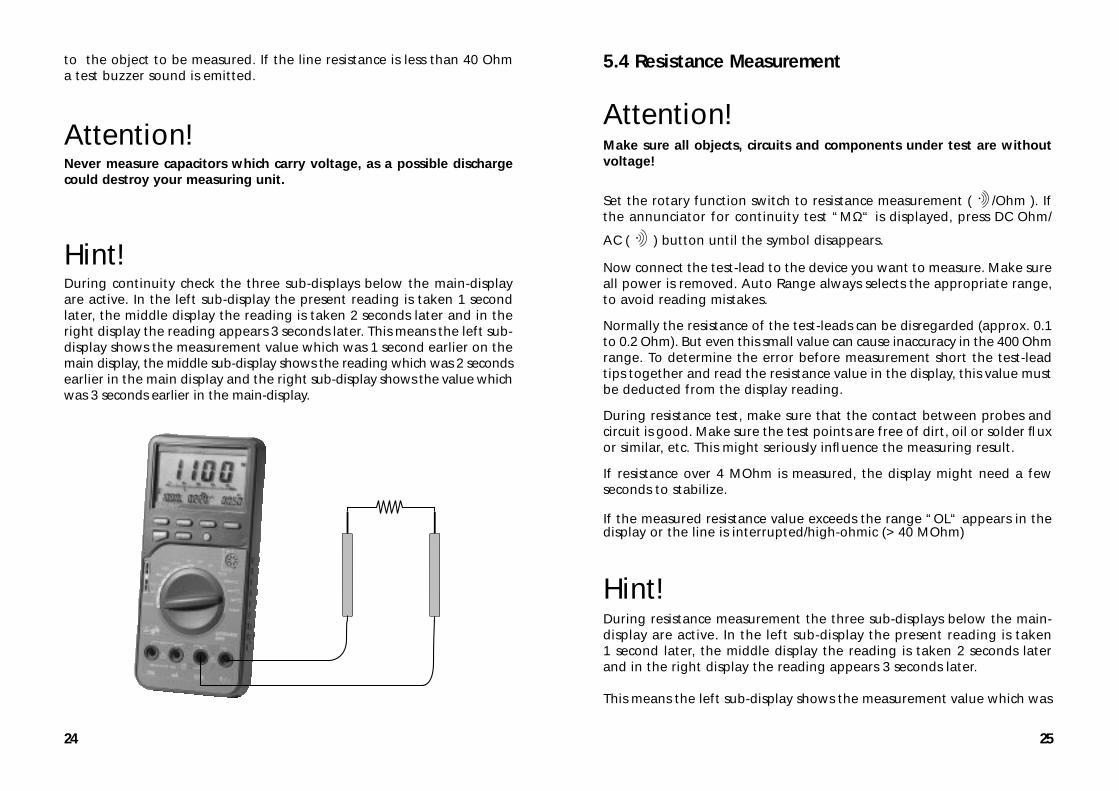
to the object to be measured. If the line resistance is less than 40 Ohma test buzzer sound is emitted.
Attention!Never measure capacitors which carry voltage, as a possible dischargecould destroy your measuring unit.
Hint!During continuity check the three sub-displays below the main-displayare active. In the left sub-display the present reading is taken 1 secondlater, the middle display the reading is taken 2 seconds later and in theright display the reading appears 3 seconds later. This means the left sub-display shows the measurement value which was 1 second earlier on themain display, the middle sub-display shows the reading which was 2 secondsearlier in the main display and the right sub-display shows the value whichwas 3 seconds earlier in the main-display.
27
• if the diode is o.k. the display will show “Good“
• if the diode is defective (short circuit) or low-ohmic “shrt“ (for short)is displayed
• If the diode is defective in the sense of high-ohmic or the test leadsare confused (red to the cathode and black to the anode) “OPEn“ for(open circuit) is displayed
5.6 Frequency Measurement
Attention!Observe the max. input limits. Never connect voltages over 750 VDC/VACrms (rms = eff).
It is life dangerous to touch the terminals or probe tips when measuringvoltages over 25 VAC or 35 VDC.
Disconnect the test-leads from the contact points when measuring vol-tage (over 25 VAC or 35 VDC) before changing the meter function andrange. The sensitive electronic of the measuring unit might be destroy-ed and you expose yourself to severe shock hazard.
Follow these steps to measure frequency:
1. Set the rotary function switch (10) to “FREQ“
2. Plug in the test-leads into the COM-socket (black = “-“) and theV/Ohm-socket (red = “+“).
3. Connect the test-lead tips with the frequency source (generator, etc.).
Hint!For most accurate measurements, we strongly recommend to use a BNC-cable (Conrad Electronic offers adapter).
26
1 second earlier on the main display, the middle sub-display shows thereading which was 2 seconds earlier in the main display and the rightsub-display shows the value which was 3 seconds earlier on the main-display.
5.5 Diode Test
Set the measuring function switch (10) to “ “. The annunciator fordiodes is displayed. Manual range selection is not possible.
Now connect the test-lead tips with the object under measurement anoff-circuit semiconductor line, the RED probe-tip to the anode, theBLACK test-lead tip to the cathode (as a rule it is marked with a colou-red ring, point etc.)
If you check a diode’s forward voltage, you will measure voltage ofapprox. 0.25 V (Germanium) or 0.7 V (Silicium), if the diode is not defective.
If you reverse the probe-tips, this means Red to the cathode and Black tothe anode, you check the so called reverse direction.
If “OL“ is displayed the diode is open or above 2.0 V forward voltage.However, if a value between 0 V and approx. 2.0 V is displayed, it showsa forward drop voltage.
The test voltage of the diode test is enough to “illuminate“ most (lowcurrent) LEDs. If the LED has an operating voltage of more than 2.0 V, theDMM displays falsely that the LED is defective.
Attention!During diode test, observe that the diode or the circuit in which it isbuilt in, must be without voltage. All existing capacities must bedischarged.
Hint!During diode test the middle sub-display is active:
29
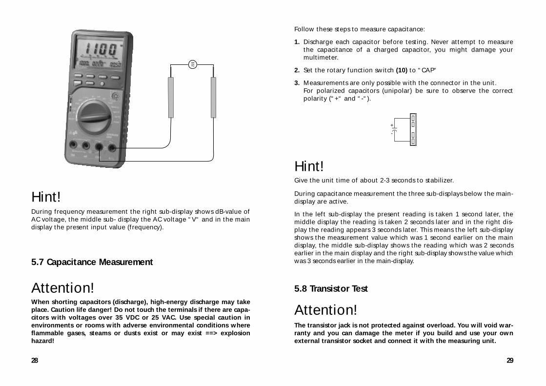
Follow these steps to measure capacitance:
1. Discharge each capacitor before testing. Never attempt to measurethe capacitance of a charged capacitor, you might damage yourmultimeter.
2. Set the rotary function switch (10) to “CAP“
3. Measurements are only possible with the connector in the unit. For polarized capacitors (unipolar) be sure to observe the correctpolarity (“+“ and “-“).
Hint!Give the unit time of about 2-3 seconds to stabilizer.
During capacitance measurement the three sub-displays below the main-display are active.
In the left sub-display the present reading is taken 1 second later, themiddle display the reading is taken 2 seconds later and in the right dis-play the reading appears 3 seconds later. This means the left sub-displayshows the measurement value which was 1 second earlier on the maindisplay, the middle sub-display shows the reading which was 2 secondsearlier in the main display and the right sub-display shows the value whichwas 3 seconds earlier in the main-display.
5.8 Transistor Test
Attention!The transistor jack is not protected against overload. You will void war-ranty and you can damage the meter if you build and use your ownexternal transistor socket and connect it with the measuring unit.
+
-
28
Hint!During frequency measurement the right sub-display shows dB-value ofAC voltage, the middle sub- display the AC voltage “V“ and in the maindisplay the present input value (frequency).
5.7 Capacitance Measurement
Attention!When shorting capacitors (discharge), high-energy discharge may takeplace. Caution life danger! Do not touch the terminals if there are capa-citors with voltages over 35 VDC or 25 VAC. Use special caution inenvironments or rooms with adverse environmental conditions whereflammable gases, steams or dusts exist or may exist ==> explosionhazard!
~~~
31
play the present reading is taken 1 second later, the middle display thereading is taken 2 seconds later and in the right display the readingappears 3 seconds later. This means the left sub-display shows the mea-surement value which was 1 second earlier on the main display, themiddle sub-display shows the reading which was 2 seconds earlier in themain display and the right sub-display shows the value which was 3 secondsearlier in the main-display.
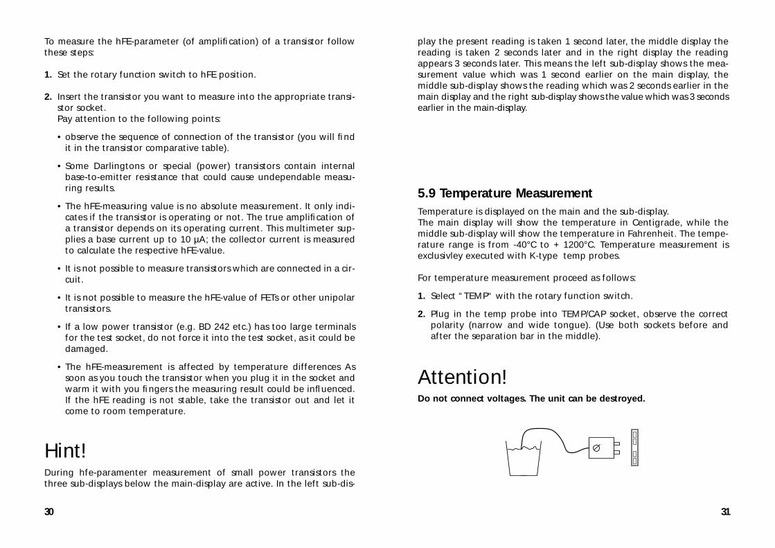
5.9 Temperature MeasurementTemperature is displayed on the main and the sub-display. The main display will show the temperature in Centigrade, while themiddle sub-display will show the temperature in Fahrenheit. The tempe-rature range is from -40°C to + 1200°C. Temperature measurement isexclusivley executed with K-type temp probes.
For temperature measurement proceed as follows:
1. Select “TEMP“ with the rotary function switch.
2. Plug in the temp probe into TEMP/CAP socket, observe the correctpolarity (narrow and wide tongue). (Use both sockets before andafter the separation bar in the middle).
Attention!Do not connect voltages. The unit can be destroyed.
30
To measure the hFE-parameter (of amplification) of a transistor followthese steps:
1. Set the rotary function switch to hFE position.
2. Insert the transistor you want to measure into the appropriate transi-stor socket.Pay attention to the following points:
• observe the sequence of connection of the transistor (you will findit in the transistor comparative table).
• Some Darlingtons or special (power) transistors contain internalbase-to-emitter resistance that could cause undependable measu-ring results.
• The hFE-measuring value is no absolute measurement. It only indi-cates if the transistor is operating or not. The true amplification ofa transistor depends on its operating current. This multimeter sup-plies a base current up to 10 µA; the collector current is measuredto calculate the respective hFE-value.
• It is not possible to measure transistors which are connected in a cir-cuit.
• It is not possible to measure the hFE-value of FETs or other unipolartransistors.
• If a low power transistor (e.g. BD 242 etc.) has too large terminalsfor the test socket, do not force it into the test socket, as it could bedamaged.
• The hFE-measurement is affected by temperature differences Assoon as you touch the transistor when you plug it in the socket andwarm it with you fingers the measuring result could be influenced.If the hFE reading is not stable, take the transistor out and let itcome to room temperature.
Hint!During hfe-paramenter measurement of small power transistors thethree sub-displays below the main-display are active. In the left sub-dis-
33
In the mode “LOGIC“ it is not possible to select function modeswith “FUNC“ button!
Attention!The voltage input of logic test is limited to max. 39.99 V. Never exceedthe maximum input limits.
Hint!During logic-level measurement, the right sub-display will show the pre-sent DC voltage value and the middle sub-display displays the frequency.
5.12 Power MeasurementTo check the power input of a consumer e.g. TV-set, stereo-set in stand-by mode or iron or bulb etc. a power meter adapter is needed. Is consistsof a plug/socket on one side and the multi-plug for the meter connectionon the other end.
First connect the multi-plug with the multimeter.Afterwards connect the load/consumer which has been switched off withthe earthing-contact socket of the adapter and finally connect theearthing-contact plug of the adapter with an earthing-contact wallsocket. Always control the correct contact of all plug connections andthe correct polarity of the multi-plug at the multimeter. The multi-plugis lettered with the current path “20 A“ on the left, in the middle withthe gounding “COM“ and on the right with the voltage path “V/Ohm“.Connect the multi-plug according to its lettering with the multimeter.
“20 A“ with the 20 A-socket, “COM“ with the COM-socket and “V/Ohm“with the V/Ohm socket.
Attention!If the connection with the multimeter is wrong or faulty, the meter, theadapter or the consumer could be destroyed. Attention! Life Danger!
32
5.10 Usage of the Analogous BargraphThe bargraph is easy to use and to understand. Is is comparable with theneedle of an analogous measuring instrument, but without its mechani-cal disadvantages. Is is especially for quick changing measuring signals,for which the digital display is too “slow“. So you can quickly recognizesee tendencies in the measuring values. If the range is exceeded the com-plete bargraph scale with an arrow on the right flashes in the display.Some functions are accompanied by an acoustic signal (mV-measure-ment).
5.11 Logic TestThis measuring function lets you easily check logic levels in digital cir-cuits.
1. Switch on your measuring unit.
2. Set the rotary switch (10) to “LOGIC“. This function displays “rdy“(=ready).
3. Connect the test-leads with the COM-input socket (black lead) andthe V-Ohm socket (red lead).
4. Now connect the other end of the black test-lead to the “ground“point of the digital circuit = “-“ (normally) and the red test-probe tothe supplying voltage point (V+ or Vcc).
5. If all leads are connected, press once Set/Reset-button to save the“High“-Level.
6. While keeping the black test-lead connected to the gound, “separa-te“ the red test-probe from the supplying voltage point (V+). Nowmove the red test-pobes to the points in question. The multimeterwill immediately display one of the three modes
• if the level exceeds 70 % of the stored supply voltage “Hi“ is dis-played.
• if the level falls below 30 % of the stored supply voltage, “Lo“ isdisplayed.
• if the level is between stored reference value = 31 % and 69 % ofthe stored supply voltage (e.g. 5 V), “——“ is displayed.
35
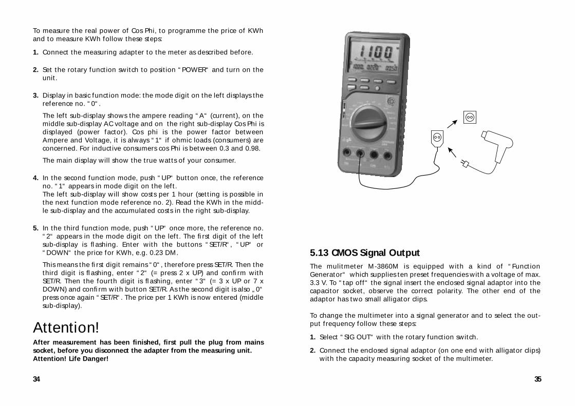
5.13 CMOS Signal OutputThe mulitmeter M-3860M is equipped with a kind of “FunctionGenerator“ which supplies ten preset frequencies with a voltage of max.3.3 V. To “tap off“ the signal insert the enclosed signal adaptor into thecapacitor socket, observe the correct polarity. The other end of theadaptor has two small alligator clips.
To change the multimeter into a signal generator and to select the out-put frequency follow these steps:
1. Select “SIG OUT“ with the rotary function switch.
2. Connect the enclosed signal adaptor (on one end with alligator clips)with the capacity measuring socket of the multimeter.
34
To measure the real power of Cos Phi, to programme the price of KWhand to measure KWh follow these steps:
1. Connect the measuring adapter to the meter as described before.
2. Set the rotary function switch to position “POWER“ and turn on theunit.
3. Display in basic function mode: the mode digit on the left displays thereference no. “0“.
The left sub-display shows the ampere reading “A“ (current), on themiddle sub-display AC voltage and on the right sub-display Cos Phi isdisplayed (power factor). Cos phi is the power factor betweenAmpere and Voltage, it is always “1“ if ohmic loads (consumers) areconcerned. For inductive consumers cos Phi is between 0.3 and 0.98.
The main display will show the true watts of your consumer.
4. In the second function mode, push “UP“ button once, the referenceno. “1“ appears in mode digit on the left. The left sub-display will show costs per 1 hour (setting is possible inthe next function mode reference no. 2). Read the KWh in the midd-le sub-display and the accumulated costs in the right sub-display.
5. In the third function mode, push “UP“ once more, the reference no.“2“ appears in the mode digit on the left. The first digit of the leftsub-display is flashing. Enter with the buttons “SET/R“, “UP“ or“DOWN“ the price for KWh, e.g. 0.23 DM.
This means the first digit remains “0“, therefore press SET/R. Then thethird digit is flashing, enter “2“ (= press 2 x UP) and confirm withSET/R. Then the fourth digit is flashing, enter “3“ (= 3 x UP or 7 xDOWN) and confirm with button SET/R. As the second digit is also „0“press once again “SET/R“. The price per 1 KWh is now entered (middlesub-display).
Attention!After measurement has been finished, first pull the plug from mainssocket, before you disconnect the adapter from the measuring unit.Attention! Life Danger!
37
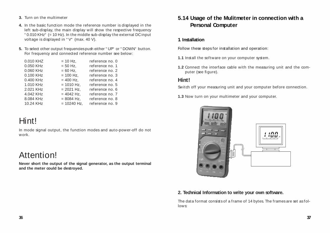
5.14 Usage of the Mulitmeter in connection with aPersonal Computer
1. Installation
Follow these steps for installation and operation:
1.1 Install the software on your computer system.
1.2 Connect the interface cable with the measuring unit and the com-puter (see figure).
Hint!Switch off your measuring unit and your computer before connection.
1.3 Now turn on your multimeter and your computer.
2. Technical Information to write your own software.
The data format consists of a frame of 14 bytes. The frames are set as fol-lows:
O 1O 20 30 4OW
36
3. Turn on the multimeter
4. In the basic function mode the reference number is displayed in theleft sub-display, the main display will show the respective frequency“0.010 KHz“ (= 10 Hz). In the middle sub-display the external DC inputvoltage is displayed in “V“ (max. 40 V).
5. To select other output frequencies push either “UP“ or “DOWN“ button. For frequency and connected reference number see below:
0.010 KHZ = 10 Hz, reference no. 00.050 KHz = 50 Hz, reference no. 10.060 KHz = 60 Hz, reference no. 20.100 KHz = 100 Hz, reference no. 30.400 KHz = 400 Hz, reference no. 41.010 KHz = 1010 Hz, reference no. 52.021 KHz = 2021 Hz, reference no. 64.042 KHz = 4042 Hz, reference no. 78.084 KHz = 8084 Hz, reference no. 8 10.24 KHz = 10240 Hz, reference no. 9
Hint!In mode signal output, the function modes and auto-power-off do notwork.
Attention!Never short the output of the signal generator, as the output terminaland the meter could be destroyed.
39
Attention!Do not use abrasive detergents, gasoline, alcohol or similar. Thesechemicals could damage the surface of the measuring unit. Besides sol-vent fumes are dangerous to your health and explosive.
7. Technical Data and Accuracy
7.1 Technical Data
Display . . . . . . . . . . . . . . . . . . . : 3 3/4-digit liquid cystal display (LCD),
maximum reading 4000 with automa-
tic polarity display
Max. Measuring Rate . . . . . . . . : 2.5 measurements per second
Max. Input Current DC/AC . . . . : 20 A
Operating Temperature . . . . . . : 0 to +40 °C, relative humidity: < 75%,
not wetting
Storage Temperature . . . . . . . . : -10°C to +50 °C, relative humidity:
< 75%, not wetting
Temperature Coefficient
for Guaranteed Accuracy . . . . . : +23 °C ± 5 K (= Kelvin)
Battery Type . . . . . . . . . . . . . . . : NEDA 1604 9 V or 6F22 9 V, alkaline
Weight . . . . . . . . . . . . . . . . . . . : 305 g ± 10 g (with 9 V battery)
Dimensions (L x W x H) . . . . . . : 187 x 84 x 34 mm (without test-leads
and adaptor)
7.2 AccuracyAccuracies are ± (% of reading = rdg + number of digit(s) = dgt(s)). Accuracy is specified at 23 °C ± 5 K with a relative humidity of below75 % not wetting for a period of 1 year after production. Warm-up timeis 1 minute.
38
BYTE 1 2 3 4 5 6 7 8 9 A B C D EExample 1) DC - 3. 9 9 9 V CRExample 2) 3. 9 9 9 MOh m CR
The sequence of data transmission from the meter:Main-display k left sub-display k middle sub-display k right sub-displayk main-display k etc.
The following program is an example of a BASIC program that getssingle reading from the meter:
OPEN “COM1 : 9600,N,7,2,RS,CS,DS,CD” FOR RANDOM AS #2PRINT #2, ”D“IN$ = INPUT$ (4 * 14, #2)PRINT IN$CLOSE #2END
Communication Specifications for Data-TransferTransfer Rate: 9600 BaudCharacter Code: 7-bit ASCIIParity: NoneStop Bits: 2
6. Maintenance and CalibrationCalibrate the meter once a year to maintain its accuracy over a longerperiod of time.
Fuse replacement is described in point 2. (Safety Rules).Battery replacement is described in point 4.1.
Clean the unit and the display with a soft, dry, antistatic cloth.
41
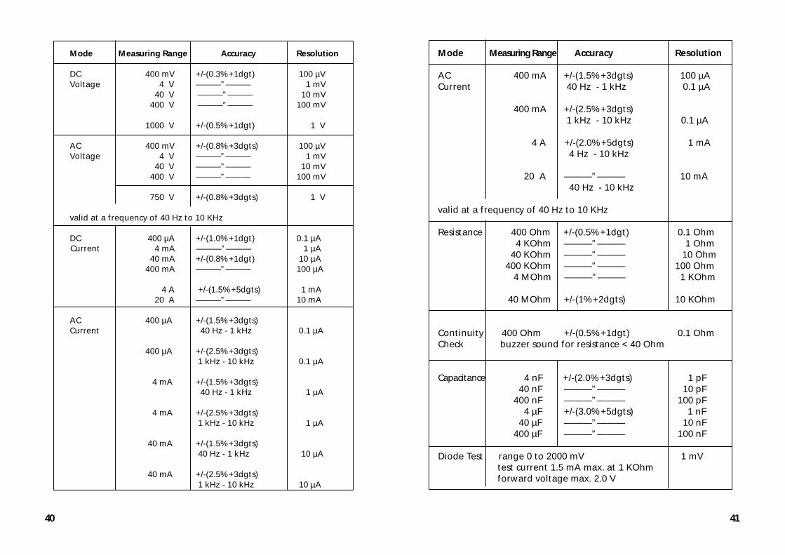
Mode Measuring Range Accuracy Resolution
AC 400 mA +/-(1.5%+3dgts) 100 µACurrent 40 Hz - 1 kHz 0.1 µA
400 mA +/-(2.5%+3dgts) 1 kHz - 10 kHz 0.1 µA
4 A +/-(2.0%+5dgts) 1 mA 4 Hz - 10 kHz
20 A ———”——— 10 mA 40 Hz - 10 kHz
valid at a frequency of 40 Hz to 10 KHz
Resistance 400 Ohm +/-(0.5%+1dgt) 0.1 Ohm 4 KOhm ———”——— 1 Ohm 40 KOhm ———”——— 10 Ohm 400 KOhm ———”——— 100 Ohm 4 MOhm ———”——— 1 KOhm 40 MOhm +/-(1%+2dgts) 10 KOhm
Continuity 400 Ohm +/-(0.5%+1dgt) 0.1 OhmCheck buzzer sound for resistance < 40 Ohm
Capacitance 4 nF +/-(2.0%+3dgts) 1 pF 40 nF ———”——— 10 pF 400 nF ———”——— 100 pF 4 µF +/-(3.0%+5dgts) 1 nF 40 µF ———”——— 10 nF 400 µF ———”——— 100 nF
Diode Test range 0 to 2000 mV 1 mV test current 1.5 mA max. at 1 KOhm forward voltage max. 2.0 V
40
Mode Measuring Range Accuracy Resolution
DC 400 mV +/-(0.3%+1dgt) 100 µVVoltage 4 V ———”——— 1 mV
40 V ———”——— 10 mV 400 V ———”——— 100 mV 1000 V +/-(0.5%+1dgt) 1 V
AC 400 mV +/-(0.8%+3dgts) 100 µV Voltage 4 V ———”——— 1 mV
40 V ———”——— 10 mV 400 V ———”——— 100 mV 750 V +/-(0.8%+3dgts) 1 V
valid at a frequency of 40 Hz to 10 KHz
DC 400 µA +/-(1.0%+1dgt) 0.1 µA Current 4 mA ———”——— 1 µA 40 mA +/-(0.8%+1dgt) 10 µA 400 mA ———”——— 100 µA 4 A +/-(1.5%+5dgts) 1 mA 20 A ———”——— 10 mA
AC 400 µA +/-(1.5%+3dgts)Current 40 Hz - 1 kHz 0.1 µA
400 µA +/-(2.5%+3dgts) 1 kHz - 10 kHz 0.1 µA
4 mA +/-(1.5%+3dgts) 40 Hz - 1 kHz 1 µA
4 mA +/-(2.5%+3dgts) 1 kHz - 10 kHz 1 µA
40 mA +/-(1.5%+3dgts) 40 Hz - 1 kHz 10 µA
40 mA +/-(2.5%+3dgts) 1 kHz - 10 kHz 10 µA
43
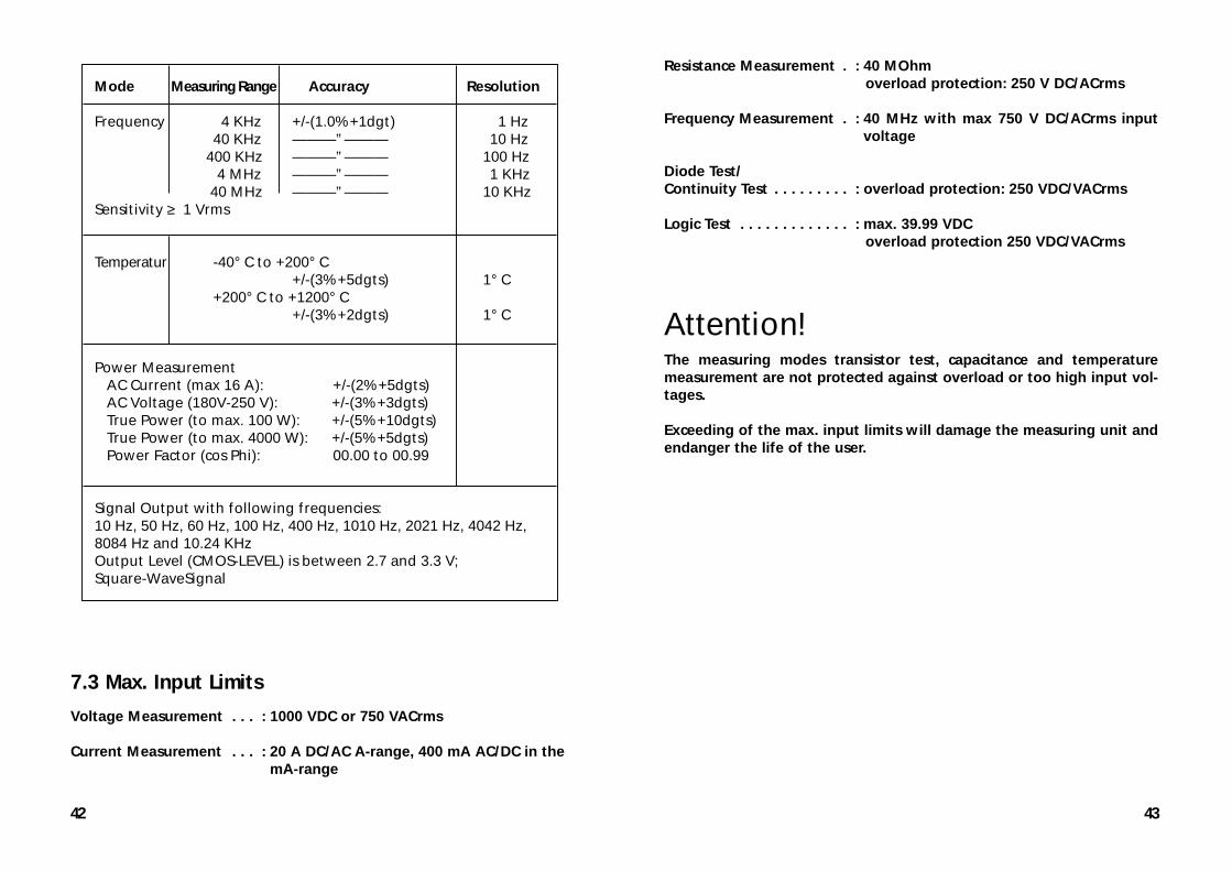
Resistance Measurement . : 40 MOhm overload protection: 250 V DC/ACrms
Frequency Measurement . : 40 MHz with max 750 V DC/ACrms inputvoltage
Diode Test/Continuity Test . . . . . . . . . : overload protection: 250 VDC/VACrms
Logic Test . . . . . . . . . . . . . : max. 39.99 VDCoverload protection 250 VDC/VACrms
Attention!The measuring modes transistor test, capacitance and temperaturemeasurement are not protected against overload or too high input vol-tages.
Exceeding of the max. input limits will damage the measuring unit andendanger the life of the user.
42
7.3 Max. Input Limits
Voltage Measurement . . . : 1000 VDC or 750 VACrms
Current Measurement . . . : 20 A DC/AC A-range, 400 mA AC/DC in themA-range
Mode Measuring Range Accuracy Resolution
Frequency 4 KHz +/-(1.0%+1dgt) 1 Hz 40 KHz ———”——— 10 Hz 400 KHz ———”——— 100 Hz 4 MHz ———”——— 1 KHz 40 MHz ———”——— 10 KHzSensitivity ≥ 1 Vrms
Temperatur -40° C to +200° C +/-(3%+5dgts) 1° C +200° C to +1200° C +/-(3%+2dgts) 1° C
Power Measurement AC Current (max 16 A): +/-(2%+5dgts) AC Voltage (180V-250 V): +/-(3%+3dgts) True Power (to max. 100 W): +/-(5%+10dgts) True Power (to max. 4000 W): +/-(5%+5dgts) Power Factor (cos Phi): 00.00 to 00.99
Signal Output with following frequencies: 10 Hz, 50 Hz, 60 Hz, 100 Hz, 400 Hz, 1010 Hz, 2021 Hz, 4042 Hz, 8084 Hz and 10.24 KHzOutput Level (CMOS-LEVEL) is between 2.7 and 3.3 V;Square-WaveSignal