Embed Size (px)
Citation preview

2110(F), 2170(F)(LBR), 1810(F) Surface Vertical Rod Exit Devices
Installation Instructions
All dimensions are in inches (mm)unless otherwise noted.
DoggingFeature to hold bolts retracted and
touchpad depressed, for push-pull dooroperation.
To Dog Device1. Insert dogging key.2. Hold touchbar depressed.3. Turn key 1/4 turn clockwise.
(Not a feature of fire labeled devices.)
PPHMS PHILLIPS PAN HEAD MACHINE SCREW
PPH”AB”SMS
PFHUMS
PFHMS
PRH”AB”SMS
PFH”AB”SMS
PHILLIPS PAN HEAD TYPE “AB” SHEET METAL SCREW
PHILLIPS FLAT HEAD MACHINE SCREW
PHILLIPS FLAT HEAD TYPE “AB” SHEET METAL SCREW
PHILLIPS ROUND HEAD TYPE “AB” SHEET METAL SCREW
PHILLIPS FLAT HEAD UNDER CUT MACHINE SCREW
FASTENER DESCRIPTIONABBREVIATION
PTH”AB”SMS PHILLIPS TRUSS HEAD TYPE “AB” SHEET METAL SCREW
PRHMS PHILLIPS ROUND HEAD MACHINE SCREW
Shim (2 supplied)
Top Strike Angleand Mounting Platefor "LBR" Devices Strike Plate
791 Strike
Top MountingPlate
(3) 10-24 x 3/4" PFHMSor (3) 10 x 1" PFHWS
2110(F), 1810(F) Top Latch
(3) 10-24 x 1/4" PPHMS
(2) 8-32 x 1/4" PFHMS
Latch Cover
(2) 6 x 3/8" PTH "AB" SMS
Guide Cover
(2) 1/4-20 x 3/4" PFHMS
Top Rod
Rod Guide
(2) 8 x 1/2" PRH "AB" SMS
Roll Pin
Top Rod Connector
Center Case
Bottom Rod Connector
Roll Pin
Rod Guide
Bottom Rod
(2) 1/4-20 x 3/4" PRHMS(Special Head)
(2) 8 x 1/2" PRH "AB" SMS
Bottom Mounting Plate
(2) 6 x 3/8" PTH "AB" SMS
Guide Cover
Deadbolt
2110(F), 1810(F) Bottom Bolt Case
(2) 1/4-20 x 3/4" PFHMS
790 Strike
(3) 10-24 x 1/4" PPHMS
Latch Cover
(2) 8-32 x 1/4" PFHMS
Cap Plug
Popper(Fire Rated Less Bottom
Rod Devices Only)
Hole Plug(Fire Devices)
Dogging Key
Rod Extension Assy
Extension Link
Fusible Extension Linkfor Fire Door Over 8'in Height
Bar Assembly(See Chart)
Packed for Reinforced Metal Doors,Optional Sex Nuts Required forUnreinforced metal, Composite
& Wood Doors.2110, 1810(Panic Label)2110F, 1810F(Fire Label)
Bottom Rod & Latch ComponentsNot Supplied With LBR (LessBottom Rod) Devices
Note: This Installation Instructions coveronly standard product. To install optionsuse installation packed with optionalcomponent, or contact the factory.
Outside TrimDevice is packed ready for any Yale
wide stile trim.
(2) 1/4-20 x 3/4" PRHMS(Special Head)
End Cap Bottom
End Cap Top (1) 10-24 x 1/2" PPH"F"TCS
#726Top Strike
12-24 PRHMS
794 Strike(Optional Fire Strike)
(4) 8-32 x 5/16" PFHUMS
Narrow CoverUsed With 2110(F),2170(F)
Attention InstallerAny retrofit or other field modification to a fire rated opening can potentially impact the fire rating of the opening, and Yale Locks & Hardware makes no representations or warranties concerning what such impact may be in any specific situation. When retrofitting any portion of an existing fire rated opening, or specifying and installing a new fire-rated opening, please consult with a code specialist or local code official (Authority Having Jurisdiction) to ensure compliance with all applicable codes and ratings.
Wide Cover Used with1810(F)
(2) 8-32 x 5/16" PFHUMS
An ASSA ABLOY Group brand
80-9421-0010-000 (05-14)

Top Latch & 791or 726 Strike Template
Device Template
Floor Strike Template
FINISHED FLOOR
Bottom Case Template
To Change Hands
Check Before Starting
Unreinforced Doors or Frames
Doors and Frames with walls having a structural thickness (metal skin plus reinforcement or solid hardwood) to engage less than (3) full screw threads are considered unreinforced.
Unreinforced Doors: Use SNB (sex nuts and bolts).
Unreinforced Frames: Use Blind Rivet Nuts.
Recommended fasteners for unreinforced openings are not necessarily supplied by Yale Locks and Hardware.
Reinforcement
Door Skin Blind Rivet Nut
Door Must Swing Freely
Min. Door Stile 4-1/2" (114mm)
Maintenance
1. Periodically remove covers and coat mechanisms with a silicone base lubricant. This is particularly required in corrosive environments for proper product function.
2. Check mounting fasteners periodically. Retighten if found loose. Apply screw locking compound (available at automotive part stores) or change part fasteners if screws continue to back out.
3. Periodic checks (and adjustments) of strikes are required to compensate for changes in the opening (e.g. door sagging).
1. Mark Door
Door and frame mustmeet structural anddimensional specificationson exit device template(s)for door and framepreparation.
2. Prepare Door, Frame, & Sill
(4) 8-32 x 3/16" PPHMS
Vertical Lifter Assembly
Remove (4) Screws andVertical Lifter Assembly.Rotate device to oppositehand (180 degrees). InsertLifter Assembly under LiftBlock and re-install screws.
Lift Block
Single Door or Pair without MullionLocate and Mark Horizontal and Vertical Reference Centerlines as shown.LHR door shown, preparation is typical for both door hands.Caution: If device is mounted higher or lower than shown, rod length must change. Lengthen or cut top and bottom rods as shown on Step 5.LBR: For Less Bottom Rod Devices, omit bottom latch and strike installation steps and see separate instructions for top latch and strike.
Note: Less Bottom Rod (LBR) Devices should not be used where security is a primary concern.
FINISHEDFLOOR
A. Locate “Device Template” aligning VERTICAL REFERENCE and HORIZONTAL REFERENCE lines. Tape template to door face.B. Extend centerline of Rod and Strikes from “Device Template” to door top and bottom, on door face.C. Locate Top Latch/Strike, Bottom Case and Bottom Strike templates aligned on centerline of Rods and Strikes on door. Tape templates in place and mark holes. Note that the centerline of the rods and strikes used to install top and bottom bolts is not the Vertical Reference centerline.D. Locate and tape Trim Template to door (See instructions packed with Trim).E. Mark and prepare holes: Device & Bolt Case Plates: Each (2) 1/4-20 Machine Screws (Metal reinforced door only.) or (2) 3/8 (10mm) Dia. Sex Nuts & Bolts Top Strike: (2) 10-24 Machine Screws or (2) #10 Wood Screws Bottom Strike: 5/8 (16mm) dia x 3/4 (19mm) deep hole
LHR Device
LHR DoorRHR Door
RHR Device
LHR DOORINSIDE FACE
VERTICALREFERENCE
HORIZONTALREFERENCE
39-15/16(1014)
LHR DOORINSIDE FACE
VERTICALREFERENCE
HORIZONTALREFERENCE
Rods & Strikes
2
Vertical Lifter Assembly
(4) 8-32 x 3/16" PPHMS
DOOR
Door Popper Templatefor LBR Devices
An ASSA ABLOY Group brand
80-9421-0010-000 (05-14)

3
3. Clear Raised Door Molding
Device must seat flush ondoor surface or on shims thatkeep it parallel to door face.
(1) Shim Kit #224
per 1/8 (3mm) of raised molding
(1) Shim Kit #224 need to clear each1/8" (3mm) of raised molding.
Longer mounting screws needed whenmore than (2) shim kits are used.
4. Mount Components
Mount 791 Top Strike(See Top Strike Detail, at right)
MountTopLatch(See Detail, at right)
16-3/8(416)
Top Latch Detail Top Strike DetailShim
(2 supplied)Start with oneStrike Plate
(Ridges FaceDown)
(2) 10-24 x 3/4" MS PFHMS
791 Strike
(2) Flat HeadScrews or SNB
TopMounting
PlateTop Latch
(3) Round HeadScrews
Note: Third screw must beinstalled after device isadjusted and works properly.See Step 6E.
NOTE: For 726 Strike &Angle/Mounting Plate, seepage 9.
Mount Rod Guide(See Rod GuideDetail, below) Note: Additional Rod Guide(s)
recommended for openings8'0" (2.45m) and higher.
To Mount Device - Follow Letter Sequence
Detail 1: Fit Bar
Center Case
Slide penetratesinto Bar
Barlies against
Center Case wall
Detail 2: To Cut Bar
Clamp Assemblywith Bar Actuatorfully depressed
Cut Square upto 6" (152mm)
Detail 3: Clamp Bar
End Cap Bottom*
Padclamps overBottom Rail
*Position to useas template formounting holes
End Cap Detail
Cap level
Cap in
Cap in place
Screw inWorksfreely
Mount Trim(Follow instructions supplied with trim)
Cutting EdgeMin. to Stile edge1/2
(13)Set Cutoff Length(See Detail 2,at left)Set Bar Level
Max. Cutout 6" (152mm)
Fit Bar(See Detail 1, at left)
2-5/8(67)
3/16(5)
1-1/4(32)Clamp Bar
Use (2) 1/4-20 PRHMS or SNB(See Detail 3, at left)Mount Center Case
Use (2) Round Head Screws(Bolt to door reinforcement,sex nuts, or trim studs)
Mount Rod Guide(See Rod Guide Detail, at right)
Device Mounting Holes, Rods & StrikesCL
15(381)
Mount 790 Floor Strike(See Detail, at right)
Rod Guide Detail(Typical 2 Places)
(2) 8 x 1/2" PRH"AB"SMS
Rod Guide• Locate Rod Guide as dimensioned. Spot (2) mounting holes.
• Prepare holes. Metal Door: .140 (3.50) dia. inside face Wood Door: .140 (3.50) dia. x 3/4" (19) deep
• Mount Guide.
Bottom Bolt Case Detail
BottomMounting
PlateBottomBoltCase
(2) Flat HeadScrews or SNB
(3) Round HeadScrews
Mount Bottom Bolt Case
Bottom Strike Detail790 Strike (Press in Place)
NOTE: Bottom Bolt will retract 1/8" (3)above Floor Strike. Floor covering inthe door path must be laid accordingly.
794 StrikeOptional
An ASSA ABLOY Group brand
80-9421-0010-000 (05-14)

4
6. Complete Installation5. Prepare Rods
Top Rod
Openings under 84" (2134mm): For Top Rod cutoff length, deduct OPENING HEIGHT from 84" (2134mm).
Example: 80" (2032mm) opening 84" (2134mm) - 80" (2032mm) = 4" (102mm) cut off of Top Rod
Opening over 84" (2134mm), subtract 84" (2134mm) from the actual opening height.
Example: 99" (2515mm) - 84" (2134mm) = 15" (381mm) extension to Top Rod
Top Rod
Top RodConnector
Flush
1/8" (3mm)x 1/2" (13mm)
Rollpin99-9999-3934-999
36-1/8(918)
Ready for 84" (2134) Openings
Bottom Rod
Bottom Rod
Bolt
1/2(13)3-7/8
(98)
32-1/4(812)
Adjustable(Ref.)
1/8" x 1/2" Rollpin99-9999-3934-999
Press Flush
Bottom RodConnector
60-1510-0280: 2" (51mm)60-1510-0277: 6" (152mm)60-1510-0278: 12" (305mm)(Specify Device Finish)
1/8(3)
Jig60-7000-1150-999
3/8(10)
To Cut Rods
Cut from end with pin hole. NEVER CUT THREADED END.
Press Jig till it bottoms over Rod.
Drill 1/8" (3.2) Dia. hole thru, 3/8" (10)from end of Rod.
To Lengthen Rods
Use rod extension(s) to extend rod to length needed orlonger (36" for 10' doors).
Cut excess length from end of rod with pin hole.
Apply screw locking compound, available at automotive partsstores, to rod extension(s) male threads. Thread extension(s)until seated tight over rod.
Ready for 39-15/16" (1014) Floor to Device Center
To Lower Device
Bottom rod cutoff length is distance that device was loweredbelow 39-15/16" (1014).
Add to top rod a length equal tothe bottom rod cut.
Example:Device at 36" (914) from floor.39-15/16" (1014) - 36" (914)= 3-15/16" (100) extension to top rod
See
CoverScrewHole
CoverScrewHole(both sides)
CoverScrewHole
CoverScrewHole(both sides)
790 Floor Strike 3/8(10) Bolt In
Bolt retracts 1/2" (13)
Check Device Slide ActionSlide should move up, at least 9/16" (14). Depress bar, activate trim, dog device. With any of these actions, the slide should move up. The slide must return to original position when bar, trim or dogging actions end.Note: If action is faulty, check for visible binding or interference. If no reason for fault is seen, remove item from door and check operation before assuming that it is defective.
Install Rods, as shownTop rod rests over device slide. Bottom rod connector hangs from device slide.
Set Top Strike Roller between Tripping Lever and Bolt.DO NOT PRELOAD BOLT.Adjust and shim strike as needed for zero door rattle.
Test Device action by Touchbar, by Trim, by Dogging.ADJUST AS NEEDED.See D1, Bottom Rod Adjustment, and D2, Top Rod Adjustment, below. Both bolts should retract, permitting free door swing. Upper bolt should retract flat. Bottom bolt should retract 1/2" (13). Bolts remain retracted until door shuts and top strike hits tripping lever.
Top Rod AdjustmentSHORTER
LONGER
TOP ROD
Note: When top bolt does not remainretracted, top rod is too short.
ROD GUIDES MUST BE DISENGAGED FROMDOOR WHILE RODS ARE ADJUSTED.
SHORTER
LONGER
BOTTOM ROD
Bottom Rod Adjustment
Note: When bottom rod drags on floorbut top rod remains retracted, bottomrod is too long.
TILT ROD OUT& TURN
TILT ROD OUT& TURN
After acceptable device function,Install third screw in top strike to lock strike in position: 10-24 x 3/4" FHMS.
Install Covers.Center case cover (4 flat head screws). Bolt case covers (2 flat head screws each). End cap top (1 pan head screw). See End Cap Detail, page 3.
An ASSA ABLOY Group brand
80-9421-0010-000 (05-14)
5
Notes:
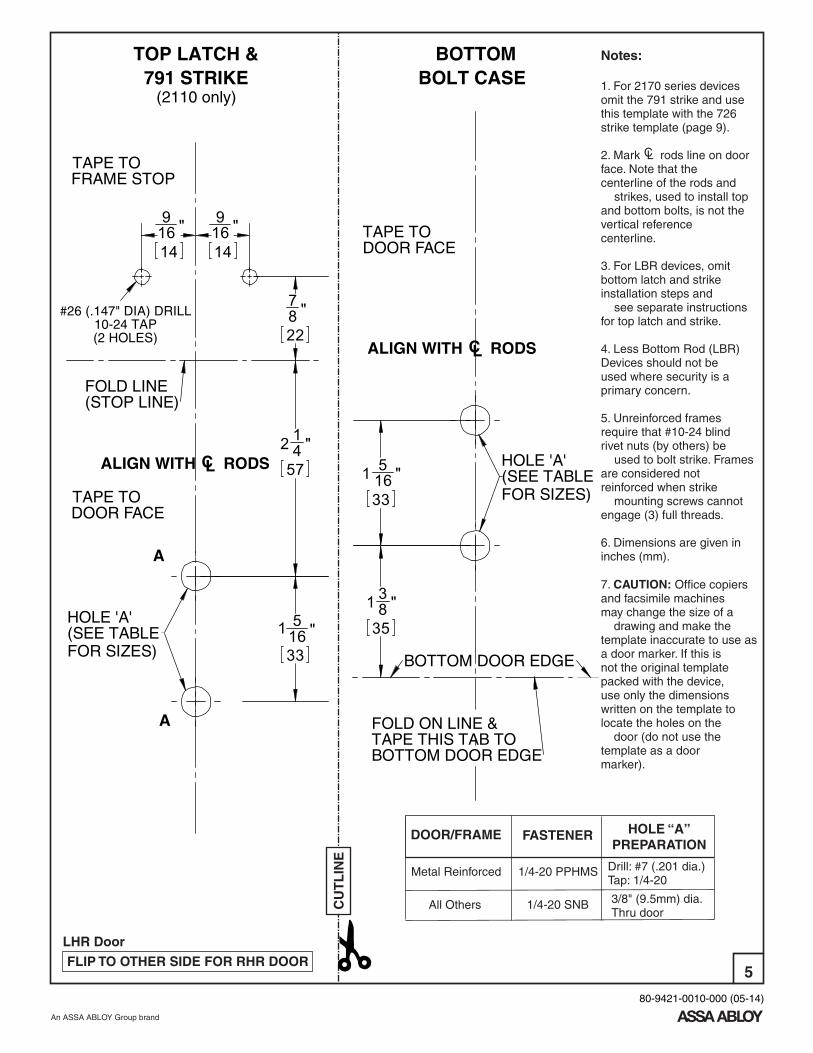
1. For 2170 series devices omit the 791 strike and use this template with the 726 strike template (page 9).
2. Mark L rods line on door face. Note that the centerline of the rods and strikes, used to install top and bottom bolts, is not the vertical reference centerline.
3. For LBR devices, omit bottom latch and strike installation steps and see separate instructions for top latch and strike.
4. Less Bottom Rod (LBR) Devices should not be used where security is a primary concern.
5. Unreinforced frames require that #10-24 blind rivet nuts (by others) be used to bolt strike. Frames are considered not reinforced when strike mounting screws cannot engage (3) full threads.
6. Dimensions are given in inches (mm). 7. CAUTION: Office copiers and facsimile machines may change the size of a drawing and make the template inaccurate to use as a door marker. If this is not the original template packed with the device, use only the dimensions written on the template to locate the holes on the door (do not use the template as a door marker).
CU
TL
INE
1416 "9
14
"169
22
"87
4 "
57
12
33
1 516 "
FRAME STOP
TAPE TO
CL RODS
(SEE TABLEFOR SIZES)
HOLE 'A'
TAPE TO
DOOR FACE
ALIGN WITH
TOP LATCH &791 STRIKE
(2110 only)
FOLD LINE(STOP LINE)
#26 (.147" DIA) DRILL10-24 TAP(2 HOLES)
A
A
C
138 "
35
1516 "
33
CL
BOTTOM
TAPE THIS TAB TO
ALIGN WITH
BOLT CASE
TAPE TO
BOTTOM DOOR EDGE
DOOR FACE
RODS
BOTTOM DOOR EDGE
HOLE 'A'
FOR SIZES)(SEE TABLE
FOLD ON LINE &
All Others
HOLE “A”PREPARATION
DOOR/FRAME FASTENER
1/4-20 SNB
1/4-20 PPHMSMetal Reinforced Drill: #7 (.201 dia.)Tap: 1/4-20
3/8" (9.5mm) dia.Thru door
LHR Door
FLIP TO OTHER SIDE FOR RHR DOOR
An ASSA ABLOY Group brand
80-9421-0010-000 (05-14)

6
This page left blank intentionally.
An ASSA ABLOY Group brand
80-9421-0010-000 (05-14)

7
58 " (16) DIA. X
3/4 (19) DEEP
LHR DOOR
FOLD LINE
790 STRIKE
DEVICE TEMPLATE
CU
TL
INE
DEVICE TEMPLATERHR DOOR
1116 "
17
1116 "
17
358 "
92
"
92
53 8
LR
OD
SC L
C LV
ER
TIC
AL
RE
FE
RE
NC
E
C L
C
HO
RIZ
ON
TAL
RE
FE
RE
NC
E
CU
TL
INE
1617
"11
CLALIGN WITH OF RODS
TAPE TODOOR FACE
Notes:
1. For 2170 series devices omit the 791 strike and use this template with the 726 strike template (page 9).
2. Mark L rods line on door face. Note that the centerline of the rods and strikes, used to install top and bottom bolts, is not the vertical reference centerline.
3. For LBR devices, omit bottom latch and strike installation steps and see separate instructions for top latch and strike.
4. Less Bottom Rod (LBR) Devices should not be used where security is a primary concern.
5. Unreinforced frames require that #10-24 blind rivet nuts (by others) be used to bolt strike. Frames are considered not reinforced when strike mounting screws cannot engage (3) full threads.
6. Dimensions are given in inches (mm). 7. CAUTION: Office copiers and facsimile machines may change the size of a drawing and make the template inaccurate to use as a door marker. If this is not the original template packed with the device, use only the dimensions written on the template to locate the holes on the door (do not use the template as a door marker).
C
An ASSA ABLOY Group brand
80-9421-0010-000 (05-14)

8
This page left blank intentionally.
An ASSA ABLOY Group brand
80-9421-0010-000 (05-14)

Notes:
1. 726 strike template for use with 2170 Series devices.
2. Mark Rods line on door face. Note that the centerline of the rods and strikes used to install top and bottom bolts, is not the Vertical Reference centerline.
3. For LBR (Less Bottom Rod) Devices, omit bottom latch and strike installation and install 726 Top Strike with Strike Angle and “Popper” assembly supplied with device.Caution: LBR Devices should not be used where security is a primary concern.
4. 726 Top Strike Installation: With door securely closed, tape template to door and frame stop. Spot and prepare holes for 726 top strike using (2) 12-24 Round Head Screws provided. With template still in-place, assemble upper mounting plate to door with the strike angle engaged into the 726 top strike, as shown below. Adjust hole locations for the mounting plate if required. Spot and prepare (2) outer holes then prepare (2) inner holes as designated on the template.
5. Unreinforced frames require that 12-24 blind rivet nuts (by others) be used to bolt strike. Frames are considered not reinforced when strike mounting screws cannot engage (3) full threads.
6. Dimensions are given in inches (mm).
7. CAUTION: Office copiers and facsimile machines may change the size of a drawing and make the template inaccurate to use as a door marker.
9
726 STRIKEFor Use With
2170 Series Devices
TAPE THIS TAB TO FRAME STOP
726Top Strike
12-24PRHMS
Top Latch Case
Strike Angle MustEngage Strike
Strike Angle and TopLatch Mounting Plate(2) Mounting Screws 1/4-20 x 3/4 PFHMS
TOP LATCH& STRIKE
FOLD(STOP LINE)
ALIGN WITH OF RODSCL
TAPE TO DOOR
DOOR FASTNER HOLE 'A'METAL
REINFORCEDSCREW 1/4-20 TAP
HOLLOW METAL &
ALUMINUM
OPTIONAL SNB
5/16 (8) DIA INSIDE DOOR FACE 3/8 (10) DIA OUTSIDE DOOR FACE
ALUMINUM SNB THRU DOOR
1-5/16"(33)
2-1/4"(57)
3/4"(19)
1/4"(6)
1/8"(3)
1/4"(6)
3/4"(19)
1/8"(3)3/4"
(19)3/4"(19)
CU
TL
INE
An ASSA ABLOY Group brand
80-9421-0010-000 (05-14)

10
Yale® is a registered trademark of Yale Security Inc., an ASSA ABLOY Group company. Other products' brand names may be trademarks or registered trademarks of their respective owners and are mentioned for reference purposes only. These materials are protected under U.S. copyright laws. All contents current at time of publication.
Yale Security Inc. reserves the right to change availability of any item in this catalog, its design, construction, and/or its materials.Copyright © 1999, 2013, Yale Security Inc., an ASSA ABLOY Group company.
All rights reserved. Reproduction in whole or in part without the express written permission of Yale Security Inc. is prohibited.
For use in conjunction with instruction sheets packed with exit device.Holes and slots are identified below by exit device series and trim. Prep door and frame for only thosefeatures required for the exit device being installed.
Frame
Door Stop
Door
Template
All 2100, 1800 Exit Devices
All 2100, 1800 Exit Devices
2120(F), 2160(F) CVR
757F StrikeLocation
Against Door Stop or Mullion(when applicable)
Vertical Reference
Wide StileTrim Only
Against Door Surface
Wide StileTrim Only
HorizontalReference
Wide StileTrim Only
Vertical Reference
Narrow StileTrim Only
2120(F), 2160(F) CVR
Plastic Installation Template 2100 Exit Devices
Product Support Tel 800.438.1951 • www.yalelocks.comYale Locks & Hardware is a division of Yale Security Inc., an ASSA ABLOY Group company.
An ASSA ABLOY Group brand
80-9421-0010-000 (05-14)