Embed Size (px)
Citation preview
Attachment Solutions
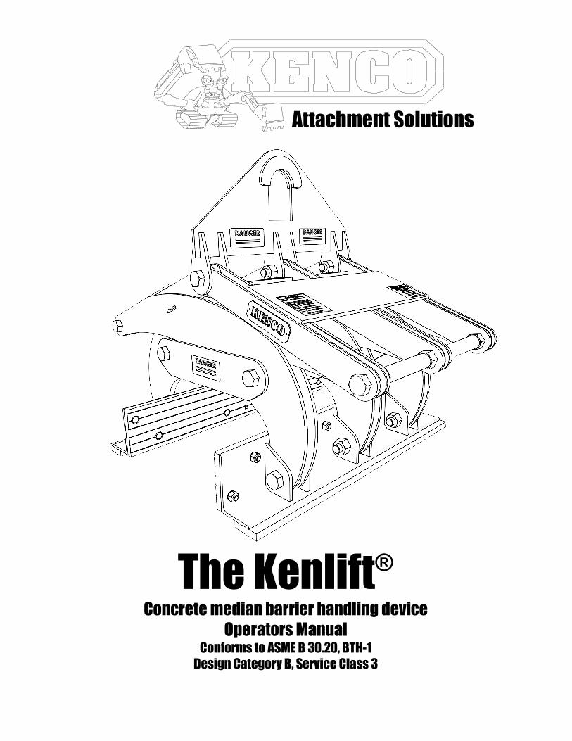
The Kenlift® Concrete median barrier handling device
Operators Manual Conforms to ASME B 30.20, BTH-1
Design Category B, Service Class 3
TABLE OF CONTENTS
Section I. General Information. ..................................................................................................... 1
Section II. Safety ............................................................................................................................... 1
Section III. Identification of Major Components ............................................................................ 3
Section IV. Setup................................................................................................................................ 3
Section V. Operation. ....................................................................................................................... 5
Section VI. Maintenance.................................................................................................................... 7
Section VII. Inspection Criteria ......................................................................................................... 8
Section VIII. Parts/Drawings............................................................................................................... 9
Section IX. Available Options ......................................................................................................... 17
Section X. Warranty....................................................................................................................... 18
RECORD INFORMATION HERE
FOR REFERENCE
MODEL
BODY SERIAL NUMBER
Notes:

KENCO Kenlift® Operation Manual
Section I. General Information
May we take this opportunity to thank you for purchasing the KENCO Kenlift®
highway median barrier wall handling system. The Kenlift®
System provides the ultimate in
below the hook concrete highway barrier handling versatility. The Kenlift®
is quality
engineered to provide years of trouble free, low maintenance performance. Please read and
fully understand this manual and any additional attached documentation before
attempting to setup, operate or maintain the Kenlift® system.
This manual should be made available to all persons who may use or maintain the
Kenlift® system. For additional information, please feel free to contact the service department
at Kenco at 1-800-653-6069
Section II. Safety
A. General
1. Safety practices described in this manual are intended as guidelines for safe operation under
most conditions and are supplementary to any and all rules and/or laws governing any aspect
of the KENCO Kenlift® operation that are in force in your area.
2. Before operating the KENCO Kenlift®, you should have a clear understanding of said laws and
regulations to ensure compliance.
3. Throughout this manual there are parts tagged with one or more of the following safety
warnings. Particular care must be exercised with regard to these statements.
B. Personal Safety
1. Wear appropriate protective clothing and related safety equipment including protective glasses,
hardhat, gloves, protective shoes, hearing protection, and any other equipment/devices dictated
by job conditions.
DANGER This warning is used where there is a high probability
of death or serious injury if the instructions are not
followed correctly.
!!!!
This warning is used where there is a possibility of
injury to yourself or others if the instructions are not
followed correctly.
WARNING !!!!
This warning is used where there is a possibility of
damage to the machine if the instructions are not
followed correctly.
CAUTION !!!!

170 State Route 271
Ligonier, PA 15658
1-800-653-6069
KENCO Kenlift® Operation Manual 2
2. Do not wear loose clothing, jewelry, or hairstyles that could become entangled in the KENCO
Kenlift® or rigging hardware.
3. Keep hands, feet, and any other appendages clear of Kenlift® while in operation.
C. Operation Safety
1. DO NOT ATTEMPT TO OPERATE OR PERFORM MAINTENANCE ON THE
Kenlift®
UNTIL READING AND FULLY UNDERSTANDING THIS MANUAL
2. MAINTAIN SAFE DISTANCE FROM LOAD - NEVER ALLOW KENLIFT® OR
LOAD TO PASS OVER ANY PART OF A PERSON.
3. DO NOT USE A KENCO Kenlift® THAT HAS BEEN ALTERED ACCIDENTALLY
OR INTENTIONALLY, IN ANY WAY WITHOUT INSPECTION BY QUALIFIED
PERSONNEL.
4. DO NOT USE A KENCO Kenlift® FOR ANY TASK OTHER THAN THE INTENDED
PURPOSE OF THE DESIGN.
KENCO Kenlift® Operation Manual
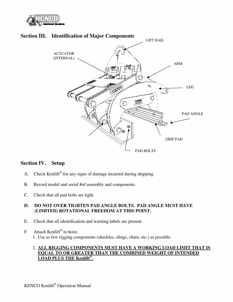
Section III. Identification of Major Components
Section IV. Setup
A. Check Kenlift® for any signs of damage incurred during shipping.
B. Record model and serial #of assembly and components.
C. Check that all pad bolts are tight.
D. DO NOT OVER TIGHTEN PAD ANGLE BOLTS. PAD ANGLE MUST HAVE
(LIMITED) ROTATIONAL FREEDOM AT THIS POINT.
E. Check that all identification and warning labels are present.
F. Attach Kenlift® to hoist.
1. Use as few rigging components (shackles, slings, chain, etc.) as possible.
2. ALL RIGGING COMPONENTS MUST HAVE A WORKING LOAD LIMIT THAT IS
EQUAL TO OR GREATER THAN THE COMBINED WEIGHT OF INTENDED
LOAD PLUS THE Kenlift®.
LIFT BAIL
PAD ANGLE
GRIP PAD
ARM
ACTUATOR
(INTERNAL)
LEG
PAD BOLTS
170 State Route 271
Ligonier, PA 15658
1-800-653-6069
KENCO Kenlift® Operation Manual 4
3. UNDER NO CIRCUMSTANCES SHOULD ANY COMPONENT USED AS RIGGING
TO Kenlift® BE OF A RATED CAPACITY LESS THAN THAT OF THE Kenlift
®.
4. DO NOT RIG UNPROTECTED NYLON SLINGS OR WIRE ROPE DIRECTLY
THROUGH LIFT BAIL.
5. IF USING EQUIPMENT OTHER THAN A CRANE: USE RIGGING OF SUFFICIENT
LENGTH TO PREVENT CONTACT BETWEEN Kenlift® AND EQUIPMENT.
KENCO Kenlift® Operation Manual
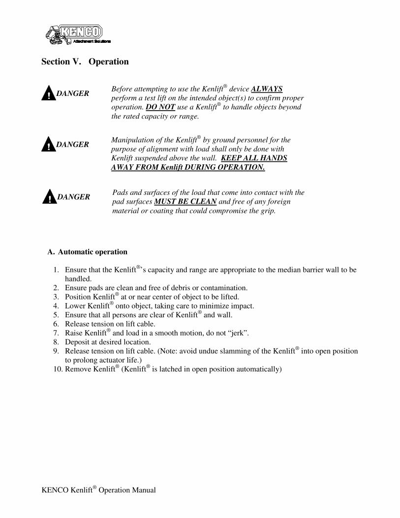
Section V. Operation
A. Automatic operation
1. Ensure that the Kenlift®’s capacity and range are appropriate to the median barrier wall to be
handled.
2. Ensure pads are clean and free of debris or contamination.
3. Position Kenlift® at or near center of object to be lifted.
4. Lower Kenlift® onto object, taking care to minimize impact.
5. Ensure that all persons are clear of Kenlift® and wall.
6. Release tension on lift cable.
7. Raise Kenlift® and load in a smooth motion, do not “jerk”.
8. Deposit at desired location.
9. Release tension on lift cable. (Note: avoid undue slamming of the Kenlift® into open position
to prolong actuator life.)
10. Remove Kenlift® (Kenlift
® is latched in open position automatically)
Manipulation of the Kenlift®
by ground personnel for the
purpose of alignment with load shall only be done with
Kenlift suspended above the wall. KEEP ALL HANDS
AWAY FROM Kenlift DURING OPERATION.
DANGER
!!!!
Pads and surfaces of the load that come into contact with the
pad surfaces MUST BE CLEAN and free of any foreign
material or coating that could compromise the grip.
DANGER
!!!!
Before attempting to use the Kenlift®
device ALWAYS
perform a test lift on the intended object(s) to confirm proper
operation. DO NOT use a Kenlift®
to handle objects beyond
the rated capacity or range.
DANGER
!!!!
170 State Route 271
Ligonier, PA 15658
1-800-653-6069
KENCO Kenlift® Operation Manual 6
B. Avoid Jarring, swinging, and otherwise unnecessary manipulation of the load.
C. Avoid handling of loads off center.
D. DO NOT USE THE Kenlift® TO PICK MULTIPLES OF ITEMS IN A SINGLE PICK.
E. Observe all safety practices associated with operation of hoist machinery.
F. DO NOT USE Kenlift® TO DRAG LOADS.
G. DO NOT ALLOW LOAD (BARRIER SECTION) TO CONTACT ANY
SURFACE/OBJECT WHILE BEING HANDLED.
The Kenlift®
barrier handling device produces grip
proportional to and dependent on the weight of the
barrier wall. It is for this reason that while in
operation the Kenlift and wall NEVER be allowed to
contact other items.
DANGER
!!!!
Tip: The majority of wear on the Kenlift®, pads, and associated components
results from shock loading, impacting, and poor alignment of the Kenlift® with
the load. Minimizing these incidents will greatly extend the life of the Kenlift ®
and consumables.
KENCO Kenlift® Operation Manual
Section VI. Maintenance
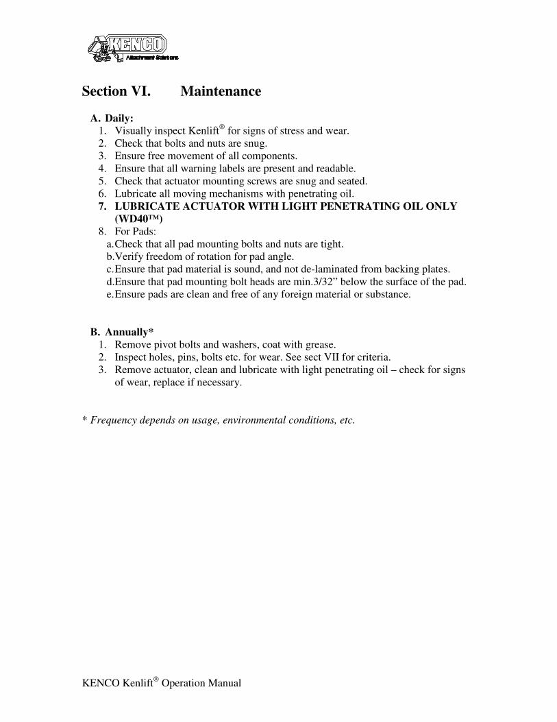
A. Daily:
1. Visually inspect Kenlift®
for signs of stress and wear.
2. Check that bolts and nuts are snug.
3. Ensure free movement of all components.
4. Ensure that all warning labels are present and readable.
5. Check that actuator mounting screws are snug and seated.
6. Lubricate all moving mechanisms with penetrating oil.
7. LUBRICATE ACTUATOR WITH LIGHT PENETRATING OIL ONLY
(WD40™)
8. For Pads:
a. Check that all pad mounting bolts and nuts are tight.
b.Verify freedom of rotation for pad angle.
c. Ensure that pad material is sound, and not de-laminated from backing plates.
d.Ensure that pad mounting bolt heads are min.3/32” below the surface of the pad.
e. Ensure pads are clean and free of any foreign material or substance.
B. Annually*
1. Remove pivot bolts and washers, coat with grease.
2. Inspect holes, pins, bolts etc. for wear. See sect VII for criteria.
3. Remove actuator, clean and lubricate with light penetrating oil – check for signs
of wear, replace if necessary.
* Frequency depends on usage, environmental conditions, etc.

170 State Route 271
Ligonier, PA 15658
1-800-653-6069
KENCO Kenlift® Operation Manual 8
Section VII. Inspection Criteria
THE KENLIFT® UNIT AND ALL OF ITS ASSOCIATED COMPONENTS
SHALL BE REMOVED FROM SERVICE AND TAGGED APPROPRIATELY
UNTIL RECERTIFICATION BY A QUALIFIED INDIVIDUAL IN ANY OF
THE FOLLOWING CONDITIONS:
A. General
1. Cracking in any component or member.
2. Cracking in any weld.
3. Visible distortion in any member.
4. Visible distortion in any Bolt/Pin/Shaft.
B. Specific
1. Lift Bail
a. The lift bail shall be replaced if a
20% loss in cross-sectional area from
the original member(s) can be
demonstrated. Note: cross section of
welds, “mushroomed” wear faces,
and burrs are not accounted for as
cross-sectional area. (See ill.)
2. Holes
a. Any members through which bolted or pinned connections pass shall be
replaced if a 10% loss in cross-sectional area from the original member(s)
can be demonstrated. Note: cross section of welds, “mushroomed” wear
faces, and burrs are not accounted for as cross-sectional area.
3. Pins/Bolts
a. Any visible deformation of a pin, shaft or bolt shall require replacement of
that part.
4. Pads – Replace if:
a. For units utilizing urethane gripping pads, if surface of any given mounting
bolt is not at least 3/32” below the surface of the pad,.
b. Any de-lamination of the pad from the backing plate.
c. Any scarring, chunking, or missing pad material constituting a total
combined loss of surface area greater than 3 sq. in. per pad.
d. Any single scar, chunk, or missing pad face that is greater than 1 sq. in per
pad.
KENCO Kenlift® Operation Manual
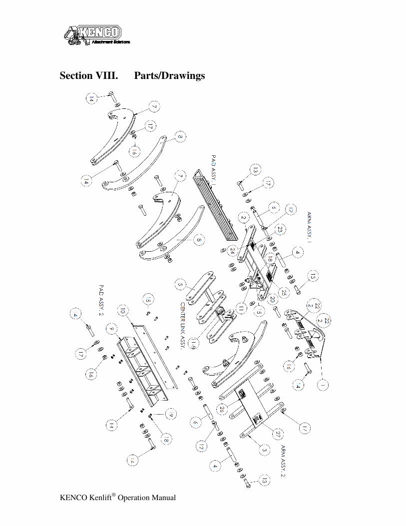
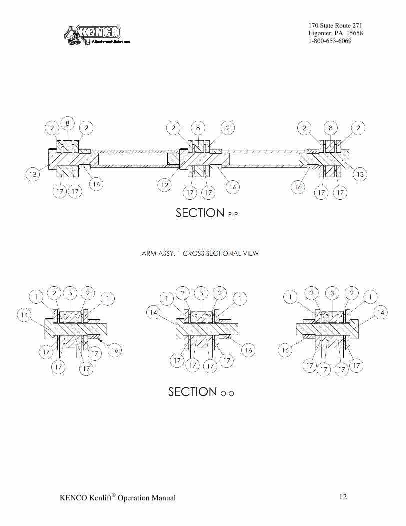
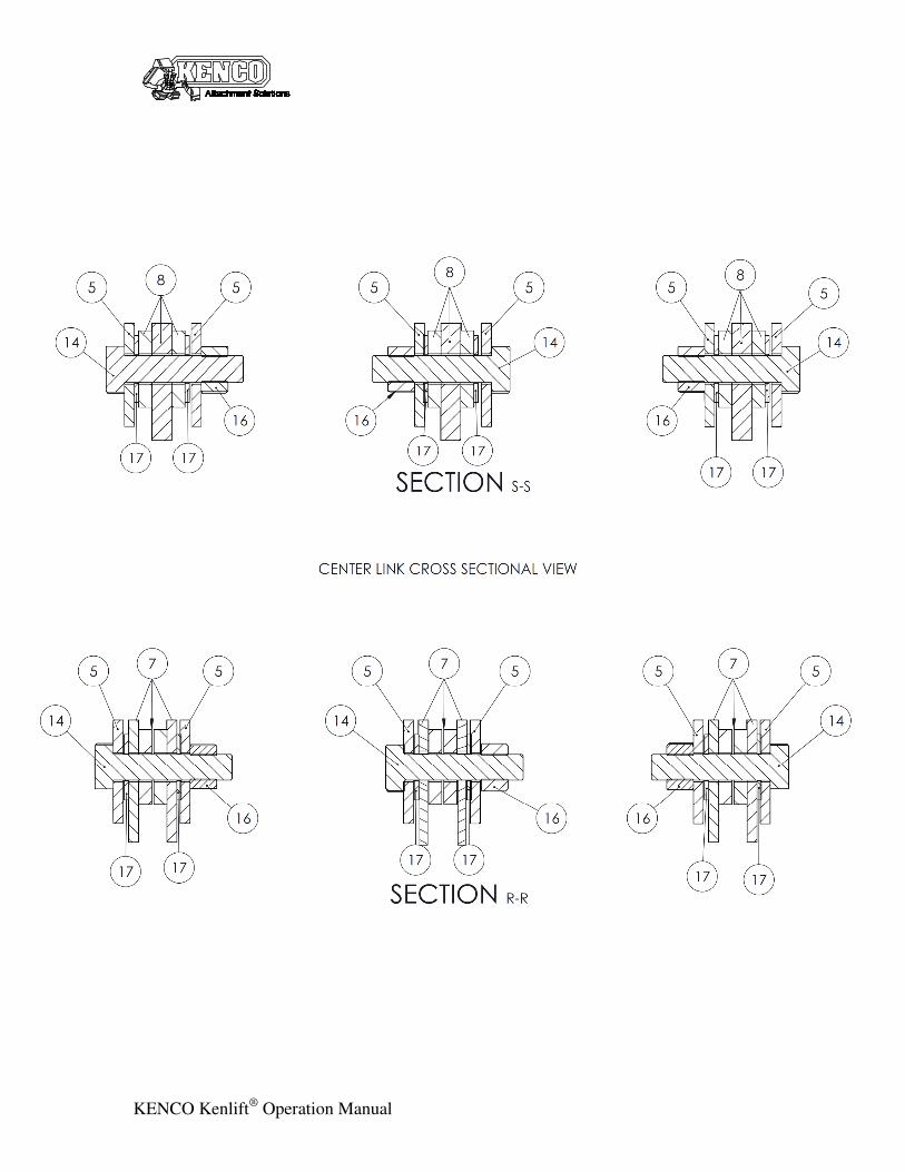
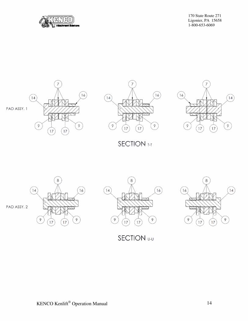
Section VIII. Parts/Drawings
170 State Route 271
Ligonier, PA 15658
1-800-653-6069
KENCO Kenlift® Operation Manual 10
2
11
1
3
4
5
6
7
8
KENCO Kenlift® Operation Manual
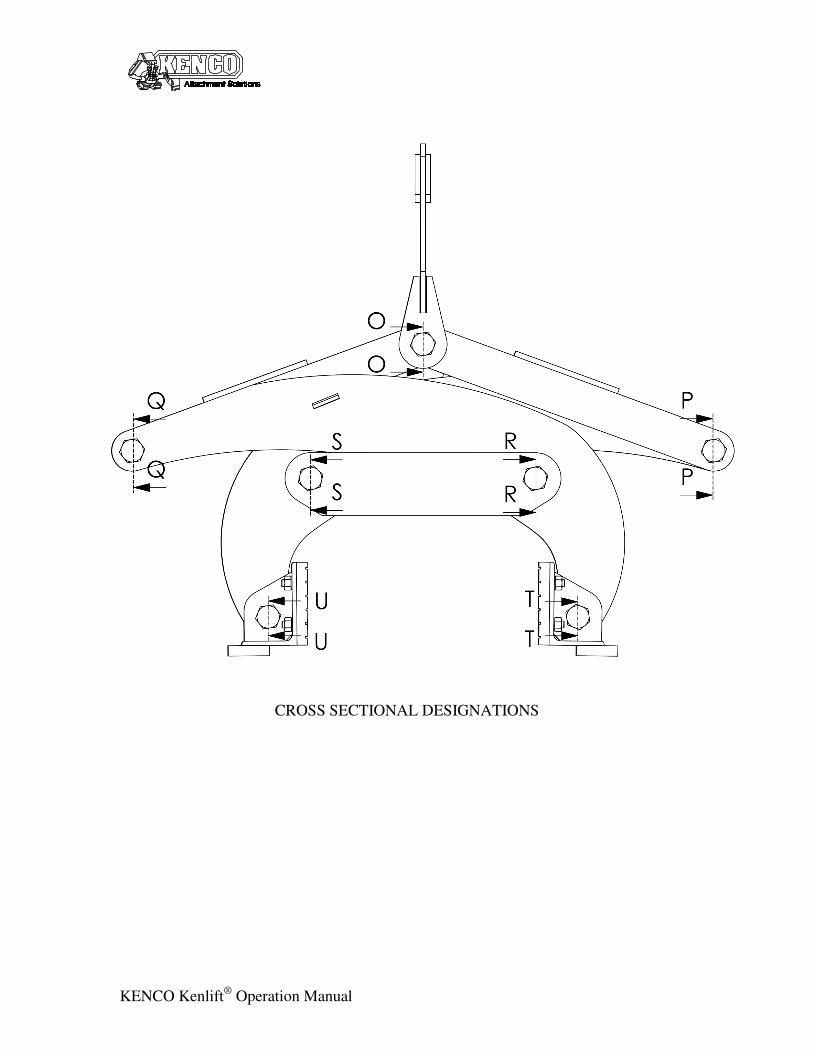
CROSS SECTIONAL DESIGNATIONS
170 State Route 271
Ligonier, PA 15658
1-800-653-6069
KENCO Kenlift® Operation Manual 12
KENCO Kenlift® Operation Manual
170 State Route 271
Ligonier, PA 15658
1-800-653-6069
KENCO Kenlift® Operation Manual 14
KENCO Kenlift® Operation Manual
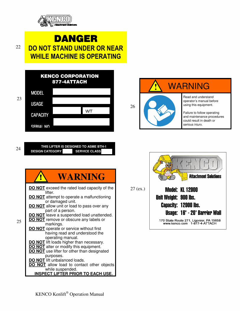
KENCO CORPORATION
877-4ATTACH
MODELMODELMODELMODEL
USAGEUSAGEUSAGEUSAGE
CAPACITYCAPACITYCAPACITYCAPACITY
SERIAL NOSERIAL NOSERIAL NOSERIAL NO. . . .
WT.
23
DO NOT exceed the rated load capacity of the
lifter. DO NOT attempt to operate a malfunctioning
or damaged unit. DO NOT allow unit or load to pass over any
part of a person. DO NOT leave a suspended load unattended. DO NOT remove or obscure any labels or
markings. DO NOT operate or service without first
having read and understood the operating manual.
DO NOT lift loads higher than necessary. DO NOT alter or modify this equipment. DO NOT use lifter for other than designated
purposes. DO NOT lift unbalanced loads. DO NOT allow load to contact other objects
while suspended. INSPECT LIFTER PRIOR TO EACH USE.
WARNING !!!!
25
Read and understand
operator’s manual before
using this equipment.
Failure to follow operating
and maintenance procedures
could result in death or
serious injury.
WARNING !
26
24 THIS LIFTER IS DESIGNED TO ASME BTH-1
DESIGN CATEGORY SERVICE CLASS
27 (ex.)
DANGERDANGERDANGERDANGER DO NOT STAND UNDER OR NEAR
WHILE MACHINE IS OPERATING
22
170 State Route 271
Ligonier, PA 15658
1-800-653-6069
KENCO Kenlift® Operation Manual 16
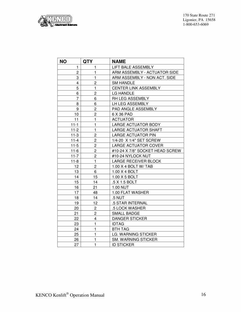
NO QTY NAME
1 1 LIFT BALE ASSEMBLY
2 1 ARM ASSEMBLY - ACTUATOR SIDE
3 1 ARM ASSEMBLY - NON ACT. SIDE
4 2 SM HANDLE
5 1 CENTER LINK ASSEMBLY
6 2 LG HANDLE
7 6 RH LEG ASSEMBLY
8 6 LH LEG ASSEMBLY
9 2 PAD ANGLE ASSEMBLY
10 2 6 X 36 PAD
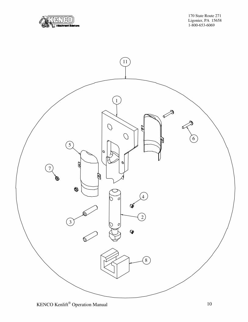
11 1 ACTUATOR
11-1 1 LARGE ACTUATOR BODY
11-2 1 LARGE ACTUATOR SHAFT
11-3 2 LARGE ACTUATOR PIN
11-4 2 1/4-20 X 1/4" SET SCREW
11-5 2 LARGE ACTUATOR COVER
11-6 2 #10-24 X 7/8" SOCKET HEAD SCREW
11-7 2 #10-24 NYLOCK NUT
11-8 1 LARGE RECEIVER BLOCK
12 2 1.00 X 4 BOLT W/ TAB
13 6 1.00 X 4 BOLT
14 15 1.00 X 5 BOLT
15 14 .5 X 1.5 BOLT
16 21 1.00 NUT
17 48 1.00 FLAT WASHER
18 14 .5 NUT
19 12 .5 STAR INTERNAL
20 2 .5 LOCK WASHER
21 2 SMALL BADGE
22 4 DANGER STICKER
23 1 IDTAG
24 1 BTH TAG
25 1 LG. WARNING STICKER
26 1 SM. WARNING STICKER
27 1 ID STICKER
KENCO Kenlift® Operation Manual
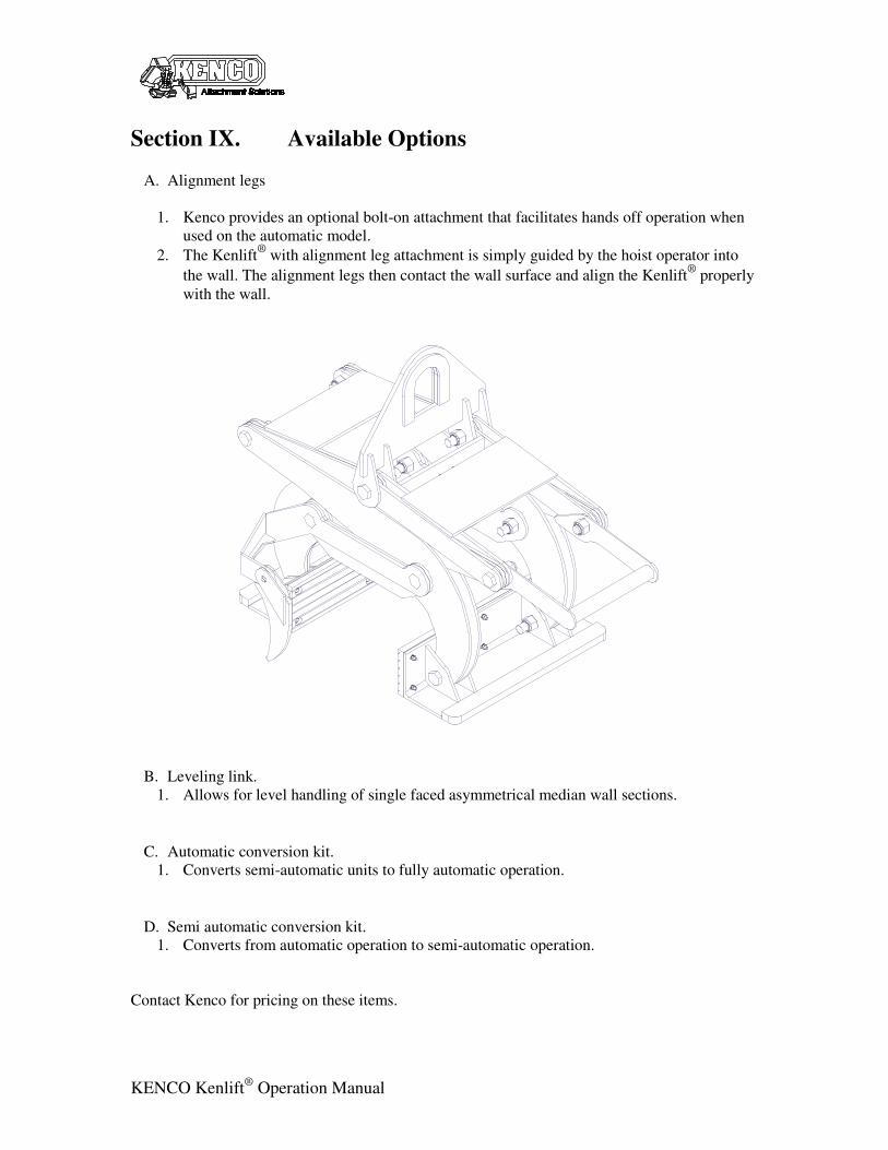
Section IX. Available Options
A. Alignment legs
1. Kenco provides an optional bolt-on attachment that facilitates hands off operation when
used on the automatic model.
2. The Kenlift®
with alignment leg attachment is simply guided by the hoist operator into
the wall. The alignment legs then contact the wall surface and align the Kenlift®
properly
with the wall.
B. Leveling link.
1. Allows for level handling of single faced asymmetrical median wall sections.
C. Automatic conversion kit.
1. Converts semi-automatic units to fully automatic operation.
D. Semi automatic conversion kit.
1. Converts from automatic operation to semi-automatic operation.
Contact Kenco for pricing on these items.
170 State Route 271
Ligonier, PA 15658
1-800-653-6069
KENCO Kenlift® Operation Manual 18
Section X. Warranty
E. Policy
1. KENCO Corporation (KENCO) warrants the KENCO Kenlift® lifting device (not
including pads or consumable items) sold by KENCO to be free from proven defects in
material and workmanship for a period of six (6) months from the delivery date to the
original customer.
2. Warranty is limited to replacement of parts and/or assemblies, which upon inspection by
KENCO are deemed to be defective in material, workmanship, or both.
3. Warranty shall not extend to products that have been altered or repaired in any way
without the express written consent of KENCO.
4. Warranty shall not extend to any product that has been misused, abused, or improperly
applied or any defect resulting thereof.
5. Defects and corrosion that are the result of improper storage and/or maintenance are not
warrantable.
6. Wear items such as Pads, Pins or Lifting bails etc. are not considered for warranty claims.
F. Disclaimer
1. THIS WARRANTY IS EXCLUSIVE AND IN LIEW OF ALL OTHER
REPRESENTATIONS AND WARRANTIES EXPRESSED OR IMPLIED, AND
KENCO EXPLICITLY DISCLAIMS AND EXCLUDES ANY IMPLIED WARRANTY
OF MERCHANTABILITY FOR A PARTICULAR PURPOSE. IN NO EVENT SHALL
THE END USER BE ENTITLED TO ANY CONSEQUENTIAL, INCIDENTAL OR
CONTINGENT DAMAGES OF ANY KIND ARISING OUT OF BREACH OF
CONTRACT, WARRANTY (INCLUDING NEGLIGENCE AND STRICT
LIABILITY) OR OTHER THEORIES OF LAW, WITH RESPECT TO PRODUCTS
SOLD OR SERVICES RENDERED BY KENCO, OR ANY UNDERTAKINGS, ACTS
OR OMISSIONS RELATING THERETO.