Embed Size (px)
Citation preview
i
OPTIMISATION OF CEILING ATTACHMENT FOR “AVPOS"
USING FEA
Bachelor Degree Project in Mechanical Engineering C-Level 22.5 ECTS Spring term 2015 Mikael Koskenranta Supervisor: Moyra McDill Examiner: Karl Mauritsson
1
Abstract
In product manufacture and assembly it is important to lower materials usage and assembly time while retaining a safety margin against structural failure. In this project the ceiling attachment of the AVPOS offloading arm is redesigned based on objectives identified by Löfs Specialmaskiner. The original ceiling attachment is analysed using finite element analysis to identify any structural weaknesses to be addressed during redesign. Based on information gained during the FEA three concepts are generated and rated based on their estimated assembly times, material usage, parts count and the cutting length for machining. One concept is selected for further topology optimisation and iterative FEA, where material is removed from the selected concept design while maintaining safety objectives. The optimised design developed during this project is shown to have a lower number of parts, lower usage of material and assembly time while retaining an overall FOS value of 4. In addition to redesigning the ceiling attachment, alternative bearings are also investigated which changes the existing ball bearings to a self-aligning sliding bearing with self-lubricating properties, lowering the machining tolerances as well as lowering the needs for service. This project contributes to lowering material usage and ease of assembly in the product AVPOS that is manufactured by Löfs Specialmaskiner. The redesigned ceiling attachment along with the suggested bearings will likely simplify future manufacturing as well as lower any concerns for damage to people and property as a result of structural failure.

ii
Certification This thesis has been submitted by Mikael Koskenranta to the University of Skövde as a requirement
for the degree of Bachelor of Science in Mechanical Engineering. The undersigned certifies that all
the material in this thesis that is not my own has been properly acknowledged using accepted
referencing practices and, further, that the thesis includes no material for which I have previously
received academic credit.
Mikael Koskenranta
Skövde 2015-05-20
Institutionen för Ingenjörsvetenskap/ Department of Engineering Science

iii
Acknowledgements I would like to use this space to extend many thanks to Löfs Specialmaskiner AB for the opportunity
to perform this final year project in mechanical engineering in collaboration with them as well as the
support they have given.
I would also like to acknowledge with gratitude the contribution of Ida Lindell in developing the
envelope of loading cases.
Furthermore, I would like to express my gratitude to my project advisor Moyra McDill for always
finding time in her busy schedule to share her engineering know-how and for all the invaluable
feedback and support she has given.

iv
Contents Abstract .................................................................................................................................................... i
Certification ..............................................................................................................................................ii
Acknowledgements ................................................................................................................................. iii
Appendices ............................................................................................................................................... v
Figures ..................................................................................................................................................... vi
Introduction ..................................................................................................................................... 1
1.1 Background .............................................................................................................................. 2
1.2 Problem Statement ................................................................................................................. 2
1.3 Limitations ............................................................................................................................... 3
1.4 Technology, Society and Environment .................................................................................... 3
1.5 Overview.................................................................................................................................. 3
Approach ......................................................................................................................................... 4
FEA of original design ...................................................................................................................... 4
3.1 FEA method ............................................................................................................................. 4
3.1.1 Geometry ......................................................................................................................... 5
3.1.2 Material properties and yield criterion ........................................................................... 6
3.1.3 Boundary conditions ....................................................................................................... 6
3.1.4 Load cases........................................................................................................................ 6
3.1.5 Solution method .............................................................................................................. 7
3.2 Analysis and key findings ......................................................................................................... 7
Design modification and preliminary concept designs ................................................................... 8
4.1 Concept generation ................................................................................................................. 8
4.2 Design for manufacture and assembly .................................................................................... 9
4.3 Screening of concept designs ................................................................................................ 12
Optimisation of the selected concept design ................................................................................ 13
5.1 Size optimisation ................................................................................................................... 13
5.2 Topology optimisation ........................................................................................................... 13
Finite Element Analysis of the Optimised Concept 2 .................................................................... 15

v
Finding suitable bearings ............................................................................................................... 15
Recommendations for new conceptual design and discussion .................................................... 16
Conclusions .................................................................................................................................... 18
References ................................................................................................................................. 18
Appendices Appendix 1 – Division of Labour
Appendix 2 – Time plan
Appendix 3 – Load cases
Appendix 4 – FEA of original ceiling attachment
Appendix 5 – Assembly times
Appendix 6 – Iterative FEA and optimisation

vi
Figures Figure 1.1 Overview of AVPOS. ............................................................................................................... 1
Figure 2.1. Breakdown of approach. ....................................................................................................... 4
Figure 3.1 Original ceiling attachment. ................................................................................................... 5
Figure 3.2 Simplified ceiling attachment ................................................................................................. 5
Figure 3.3. Typical mesh after refinement. ............................................................................................. 5
Figure 3.4. Boundary conditions. ............................................................................................................ 6
Figure 3.5. Load contact points. (Lindell, 2014) ...................................................................................... 7
Figure 3.6. Hot spots and bending in the ceiling attachment. Load case 5. ........................................... 7
Figure 3.7. High stresses in load case 7. .................................................................................................. 7
Figure 4.1. Points in the original ceiling attachment between which distances may not change. ......... 8
Figure 4.2. Concept 1............................................................................................................................... 8
Figure 4.3. Concept 2............................................................................................................................... 9
Figure 4.4. Concept 3............................................................................................................................... 9
Figure 5.1. Factor of safety of Concept 2 after thickness optimisation. ............................................... 13
Figure 5.2. Result of removing material in the first iteration of topology optimisation. ...................... 14
Figure 5.3. Iso-cutout showing areas with stresses greater than 15 MPa for load case 7.................... 14
Figure 5.1. Final model of Concept 2. .................................................................................................... 15
Figure 6.2. FOS for the final model for load case 7. .............................................................................. 15
Figure 8.1. Close-up of milled slots. ...................................................................................................... 17
Figure 8.2. Completed redesign of Concept 2 mounted on the swing arm. ......................................... 17
Table 3.1. Material properties of Plancast Plus 5083(n) (Löfs Specialmaskiner AB, 2014b). .................. 6
Table 4.1. DFA evaluation of the original ceiling attachment. (Boothroyd, Dewhurst, & Knight, 2002)
............................................................................................................................................................... 10
Table 4.2. Contour lengths and thicknesses. ......................................................................................... 11
Table 4.3. Pugh selection matrix for Concept 1-3. ................................................................................ 12
Table 8.1. Objectives. ............................................................................................................................ 16
Figures and tables for appendices are listed separately in each appendix.

1
Figure 1.1 Overview of
AVPOS.
A – Ceiling attachment
B- Swing arm
C – End effector
Image courtesy of Löfs
Specialmaskiner AB.
Introduction Although the steady improvements in power sources and machining capabilities throughout history
have greatly improved the rate and quality of production, worker health and safety were often
overlooked or entirely absent. It took until the late 1800’s for the creation of laws limiting the use of
child labour in Britain (Venning, 2010). Similarly in Sweden, children under the age of 14 made up
over 5% of the workforce in 1875 and it was not until 1949 that child labour was abolished by law
(Forsström, 2010).
Today there exist several organisations, unions, and laws meant to protect workers from injury and
ill-health. One such organisation is the Swedish Work Environment Authority which has published
regulations relating to workplace ergonomics. One of these regulations states that the employer
must provide a workplace where fatigue and injuries to the body in general, and the back and spine
in particular, due to heavy lifting or repetitive work are minimised, preferably by offloading such
work by the use of technical equipment (Arbetsmiljöverket, 2012).
One way to offload physically exerting operations from a human
operator is to use a powered torque arm or offloading arm. There
are several types of both manual and powered torque arms and
offloading arms being produced today by several manufacturers,
such as Atlas Copco (Atlas Copco, 2015) and Givens Engineering
(Givens Engineering Inc., 2011). The main drawback of most pre-
existing torque arms is their slow and cumbersome operation,
often caused by having long horizontal members, or by having
only a small work area (Löfs Specialmaskiner AB, 2014b).
Löfs Specialmaskiner AB (LS) is a small company which mainly
works with customized machines and mechanical construction in
project form (Löfs Specialmaskiner AB, 2014a). LS is attempting to
solve the problems with existing offloading systems by developing
a pneumatically powered offloading arm, mounting it directly
above the workstation and by using a pneumatic balancing system
to cancel out the forces that would be transmitted to the operator
(Löfs Specialmaskiner AB, 2013).
LS has purpose-designed AVPOS (Avlastnings- och
positioneringsarm), a unique tool which eases manual assembly
operations performed by an operator at a workstation, such as
lifting operations or offloading the torque from a powered torque
wrench from the operator as shown in Figure 1.1. As such AVPOS
is not only intended as a tool for offloading operations such as
tightening bolts, but also has the ability to be used as a lifting tool
for objects up to 20 kg (Löfs Specialmaskiner AB, 2013).
AVPOS is built as a pendulum that is free to swing around two

2
axes, allowing the lower end to be positioned anywhere on a two-dimensional plane. With the
extension of the swing arm this enables a large three-dimensional volume to be used as a work area.
The swing arm (B) of AVPOS is balanced by a pneumatic cylinder at its top which can keep the arm
stationary at any point in its swing, as well as aid in lifting small loads or prevent movement when the
end effector (C) holds a tool such as a torque wrench. The swing arm (B) and pneumatic cylinder are
held up by a ceiling attachment (A).
1.1 Background
Only simple stress calculations have been performed by LS of the component parts of AVPOS to
ensure they can manage intended loads. The ceiling attachment has to date not deformed nor failed
destructively, but the ceiling attachment needs to be further analysed and developed to ensure
required performance in regards to both operator safety and manufacturing costs (Löfs
Specialmaskiner AB, 2014b).
This work is performed to suggest an improved ceiling attachment for the industrial tool AVPOS in
such a way that it is easier and less expensive to manufacture, assemble and is safe to use. These
improvements are expected to come in the form of fewer component parts, fasteners and better
defined safety margins. The bearings used in the ceiling attachment are also to be investigated for
suitability in regards to the expected loads and a suitable replacement suggested.
This bachelor’s degree project is performed in collaboration with Löfs Specialmaskiner AB, in an
effort to lower the manufacturing cost of a mechanical offloading and positioning system through
the simplification of its ceiling attachment.
1.2 Problem Statement
The existing design needs to be analysed to determine any structural limitations to be improved as
well as propose a new design (Löfs Specialmaskiner AB, 2014b) that is:
easier to assemble,
has less than half the number of parts and fasteners,
has a material usage that is lower by at least 20%,
has a factor of safety of 4 in regards to plastic deformation,
made from machined aluminium plates (Löfs Specialmaskiner AB, 2014b),
possible to swap with the current design without further changes to the rest of the system.
Material costs should be kept as low as possible by using thin aluminium plates where waste from
machining can be minimised (Löfs Specialmaskiner AB, 2014b). As the price of aluminium plates is
directly related to the weight, rather than the dimensions, thinner plates are preferred where
possible to minimise materials cost before machining operations.
LS has determined that the greatest possible loadings from misuse are likely to be caused by
the total weight of a person hanging on the arm (as if by falling and grabbing onto the arm),
and a person pushing on the arm at any of the end positions.

3
In addition to these cases of misuse, LS requires that the arm must withstand regular usage such as
the force from an attached torque wrench set to 200 Nm. The swing arm is considered to be at most
4 m in length.
1.3 Limitations
Only the ceiling attachment and bearings are to be studied and optimised, other parts of AVPOS as
well as the bolts connecting the ceiling attachment to external points are to be assumed stiff.
Changes to manufacturing methods are to be avoided, i.e. made from machined aluminium plate.
Changes to the rest of AVPOS aside from the ceiling attachment are also to be avoided.
1.4 Technology, Society and Environment
Repetitive movements and fatigue often appear in the work place which over time lead to a lower
work output and injuries (Emery & Côté, 2012). To combat the effects of fatigue and work place
related injuries the Swedish Work Environment Authority recommends that physical work should be
performed in front of the body with relaxed back, arms and shoulders (Arbetsmiljöverket, 2012). To
prevent heavy loading of these areas of the body a tool such as AVPOS can be a good aid. For AVPOS
to be able to be used in the intended manner it needs to be deemed safe and malfunctions should
not cause users any harm. The ceiling attachment is one important part of the system in regards to
safety and according to the Swedish Work Environment Authority the strength of any load bearing
part needs to be ensured (Arbetsmiljöverket, 2006).
Aluminium exposure is currently one of the lesser environmental problems, but production and
refinement of aluminium are linked to the release of fluorides which can cause skeletal fluorosis in
animals as well as cause so-called “aluminium asthma” in workers in the aluminium plants
(Environmental and Health Aspects Related to the Production of Aluminium, 1994). Exposure and
uptake of aluminium is known to cause renal failure and may also be linked to neurodegenerative
disorders, such as Alzheimer’s disease (Kumar & Gill, 2009). Although aluminium is less toxic than
many other metals, lowering any unnecessary use of aluminium is preferable. As such, ensuring the
lowest possible usage of aluminium in the production of the ceiling attachment of AVPOS will lower
the impact on the environment as well as the monetary cost of the starting materials.
1.5 Overview
In this project the main concern is to determine any structural weaknesses in the original ceiling
attachment by FEA (finite element analysis). To perform this FEA the boundary conditions, geometry
and material properties are investigated. (Section 3. FEA of original design).
Following the initial analysis a redesign of the ceiling attachment is performed, in Section 4. Design
modification and preliminary concept designs, by generating concepts which could be interchanged
with the original ceiling attachment and then evaluating these using a Pugh selection-matrix. This
matrix contains the assembly time, initial weight, cutting length and parts count of each concept as
screening criteria.
Optimisation to the weight and material usage is performed in Section 5. Optimisation of the
selected concept design. A final verification of the redesign is made in Section 6,

4
Figure 2.1. Breakdown of approach.
Finite Element Analysis of the Optimised Concept 2.
New bearings are investigated in Section 7, Finding suitable bearings. The optimised design of the
ceiling attachment is proposed in Section 8,
Recommendations for new conceptual design and discussion. Finally, a series of appendices with
more detailed analyses are attached.
Approach As the tool is mounted above the work area where the operator is present, there are safety concerns
regarding the strength of the attachment, in addition to the concerns of lowering manufacturing
costs. To address these concerns a systematic approach is used as outlined in Figure 2.1.
To determine weaknesses in the existing ceiling attachment a FEA is performed. To accomplish that
task any applicable simplifications and assumptions are determined, as well as what loads and
boundary conditions to apply.
Load cases have been previously determined in 2014 (Lindell, 2014) and are presented in Appendix 3.
These load cases are used as a starting point for the FEA. Knowing the expected loads also makes it
possible to search for suitable replacement bearings and gives pointers to new concept designs.
FEA of original design
3.1 FEA method
Modelling and FEA for this project were performed using the software Solidworks1 which has several
modules for analysis and optimisation. Of these modules only the modelling and static FEA were
used.
The steps that were taken to produce meaningful output from the FEA were:
1. Creation of a suitably simplified model.
2. Determination of load cases and boundary conditions.
1 Solidworks 2014 SP 2.0
5
3. Mesh creation, application of loads and boundary conditions.
4. Interpretation of the results.
The full analysis and results are presented in Appendix 4.
3.1.1 Geometry
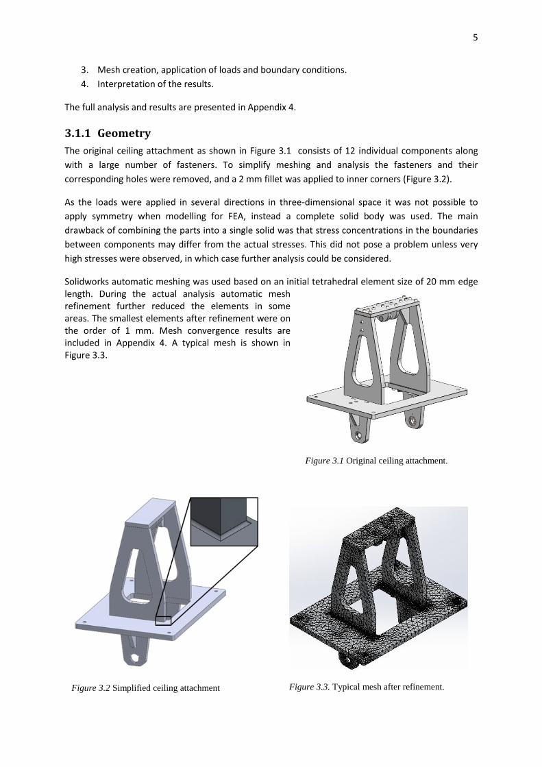
The original ceiling attachment as shown in Figure 3.1 consists of 12 individual components along
with a large number of fasteners. To simplify meshing and analysis the fasteners and their
corresponding holes were removed, and a 2 mm fillet was applied to inner corners (Figure 3.2).
As the loads were applied in several directions in three-dimensional space it was not possible to
apply symmetry when modelling for FEA, instead a complete solid body was used. The main
drawback of combining the parts into a single solid was that stress concentrations in the boundaries
between components may differ from the actual stresses. This did not pose a problem unless very
high stresses were observed, in which case further analysis could be considered.
Solidworks automatic meshing was used based on an initial tetrahedral element size of 20 mm edge length. During the actual analysis automatic mesh refinement further reduced the elements in some areas. The smallest elements after refinement were on the order of 1 mm. Mesh convergence results are included in Appendix 4. A typical mesh is shown in Figure 3.3.
Figure 3.2 Simplified ceiling attachment
Figure 3.1 Original ceiling attachment.
Figure 3.3. Typical mesh after refinement.

6
3.1.2 Material properties and yield criterion
The material used in the ceiling attachment is an aluminium alloy called Plancast Plus 5083(n) (Löfs
Specialmaskiner, 2014), which is ductile and has a linear elastic region with the properties outlined in
Table 3.1. These properties were used in all FEA. Small deformations were assumed for the analyses,
as such the material behaves as linear elastic. If large deformations would have been observed this
would have been revised.
Table 3.1. Material properties of Plancast Plus 5083(n) (Löfs Specialmaskiner AB, 2014b).
Yield strength: 1.25e+008 N/m2 Poisson's ratio: 0.33
Tensile strength: 2.5e+008 N/m2 Mass density: 2660 kg/m3
Elastic modulus: 6.9e+010 N/m2 Shear modulus: 2.59e+010 N/m2
The ceiling attachment is a 3D structure required to withstand several loading cases in different
directions, which means calculations need to be performed using generalised equations with a
suitably chosen effective stress yield criterion. As the material used in the ceiling attachment is
loaded within its linear elastic region von Mises effective stress was chosen as a suitable yield
criterion (Sundström, 1998).
3.1.3 Boundary conditions
The ceiling attachment is constrained by four fastening holes at the corners. For FEA modelling
purposes these fastening holes were surrounded by a small, raised, puck-shaped features as shown
in Figure 3.4. These were used to apply the constraints. One (A) was constrained from movement in
any direction while the remaining three were prevented from out-of-plane movement (Figure 3.4).
Defining the constraints this way served two purposes; it was possible to apply the constraint to a
smaller area than the entire bottom surface and it allowed some out-of-plane deflection to occur.
3.1.4 Load cases
A total of thirteen important load cases were previously identified (Lindell, 2014), however, under
closer examination several of the cases were found to be similar and it was possible to lower the
number of analyses to perform to eight, as follows:
1. the swing arm hanging straight down with a person’s weight and a load of 20 kg on it,
2. the swing arm hanging straight down with an applied moment of 200 Nm,
Figure 3.4. Boundary conditions.

7
Figure 3.6. Hot spots and bending
in the ceiling attachment. Load
case 5.
Figure 3.5. Load contact points. (Lindell,
2014)
Figure 3.7. High stresses in load case 7.
3. an applied horizontal load in the positive x-direction from a person pushing on the lower
end of the swing arm and a load of 20 kg,
4. an applied moment of 200 Nm with the swing arm in the positive x-direction,
5. an applied horizontal load in the positive y-direction from a person pushing on the lower
end of the swing arm and a load of 20 kg,
6. an applied moment of 200 Nm with the swing
arm in the positive y-direction,
7. an applied horizontal load in the positive x=y-
direction from a person pushing on the lower
end of the swing arm fully in the positive x
and y-direction and a load of 20 kg, and
8. an applied moment of 200 Nm with the swing
arm fully in the positive x and y-direction.
In the FEA the loads, as described fully in Appendix 3,
were applied at the five contact points A through E as
seen in Figure 3.5.
3.1.5 Solution method
The solution method used was FFEPlus with h-adaptive mesh refinement. FFEPlus is an iterative
solver and was chosen mainly as it is much faster than a direct solver, but it has low errors when
used for static analyses (Dassault Systèmes, 2015). The reason h-adaptive was chosen is because
meshing errors were very common when attempting to use a p-adaptive method, and time did not
allow for drawn-out troubleshooting.
3.2 Analysis and key findings
The purpose of the FEA of the original ceiling attachment was to identify areas in which re-design or
modification were necessary. Careful observation of the results (fully presented in Appendix 4)
showed that for most load cases there was no risk of plastic deformation and overall the stresses did
not propagate far from very small hot-spots at inner edges.
Stress hot-spots often appeared where the vertical pieces attach to the mounting plate as can be
seen Figure 3.6, as the upper vertical pieces were not in line with the lower which gave rise to a

8
bending moment in the mounting plate. This could be avoided by aligning any load bearing members.
The most severe load case is number 7, which occurs when an operator tries to push the swing arm
outside its operating area while the arm is carrying a 20 kg payload. In Figure 3.7 large areas of the
horizontal plate at the midsection show high stresses nearing the yield limit of the material as well as
a few hot spots in corners where plastic deformation is likely to occur. The stresses do not propagate
entirely through the large plate so structural collapse is unlikely. By aligning the load bearing
members the bending moment in the large plate could likely be lowered.
Overall the original ceiling attachment could handle normal usage well, but more severe loading
caused hot spots in some areas while other parts were mostly unaffected. With a careful redesign
material usage could be lowered while at the same time prevent similar hot spots from appearing.
Design modification and preliminary concept designs
4.1 Concept generation
Concept generation was performed by keeping in
mind the distances between axles and contact
points which because of the interchangeability
requirement could not be altered from the original
design (Figure 4.1). The approach taken was to
sketch ways to connect these points using plate
material.
Several concepts were produced, but upon closer
examination only three of these were found
suitable for further development. These concepts
were named Concepts 1 to 3 in no particular order.
Concept 1, presented in Figure 4.2, consisted of five
parts cut from aluminium plates, with a horizontal
centre plate like in the original ceiling attachment
and two vertical sides. The sides slot into a notch cut in the centre plate to help transfer the weight
Figure 4.1. Points in the original ceiling
attachment between which distances may not
change.
Figure 4.2. Concept 1.

9
Figure 4.3. Concept 2.
Figure 4.4. Concept 3.
of the swing arm and payload to the attachment points in the ceiling, without loading any connecting
screws between the sides and the centre plate with large shear stresses. In addition to combining the
separate top and bottom vertical pieces from the original ceiling attachment into a single vertical
piece per side, the top axle was rotated ninety degrees in relation to the bottom axle which could
then be connected to the vertical sides with only two slender plates.
Concept 2, shown in Figure 4.3, was also made up of five components but used a different layout
compared to Concept 1 and the original ceiling attachment. In this concept the slender top plates
were extended down to the centre plate in an inverted V configuration. At the centre plate both the
lower and upper vertical plates meet, where they were all joined orthogonal to each other, which
was thought could improve the stability of the overall structure.
In Figure 4.4 it can be seen that Concept 3 is similar to Concept 1 with a few key differences. In this
concept the side plates were extended to provide attachment points instead of placing these on the
centre plate and slots have been cut to offload shear stress from screws between the sides and other
components.
4.2 Design for manufacture and assembly
A common way of lowering material, manufacturing, and assembly costs is to use the method named
as Design for manufacture and assembly (DFMA). DFM is mainly concerned with producing single
components with as few and as simple operations as possible, whereas DFA is interested in designing
components to be easy to assemble with as few parts as possible. Bogue (2012) presents broad
guidelines for applying DFMA when optimising an existing assembly:

10
minimise parts count,
minimise use of custom parts,
use fewer fasteners, preferably of the same size and type,
design for a specific assembly technique,
keep simple manufacturability in mind.
Product assembly time is an important metric that directly impacts the final cost and can be
estimated using tables of assembly times. These tables were developed by Boothroyd and Dewhurst
in the early 1980’s (Boothroyd, Dewhurst, & Knight, 2002) and take into account the size and
symmetry of the parts being assembled, as well as how easy they are to align and if parts needs to be
held in place while screws are inserted.
The original ceiling attachment as well as the three generated concepts were evaluated using the
Boothroyd and Dewhurst assembly time method. To avoid bias in relation to the original ceiling
attachment, screws were incorporated into the concepts. In areas where the load is transferred by
the use of slots where the parts mate only the minimum number of screws was used, whereas other
areas used more screws. As this was an initial estimation of assembly time no calculation of shear
forces in the screws was performed.
According to the Boothroyd and Dewhurst method, assembly of the original ceiling attachment
would take 282 seconds, without taking into account the time it would take to acquire any tools
between operations as this is highly dependent on the specific assembly station layout. In Table 4.1 a
summary of the full evaluation is presented. The detailed evaluation is presented in Appendix 5.
Table 4.1. DFA evaluation of the original ceiling attachment. (Boothroyd, Dewhurst, & Knight, 2002)
No
. o
f it
em
s
RP
Han
dlin
g
cod
e
Han
dlin
g
tim
e T
H
Inse
rtio
n
cod
e
Inse
rtio
n
tim
e TI
Tota
l ti
me
RP
*(T
H+T
I) Comment
1 Top plate 1 0 0 1.13 0 0 1.5 2.63 First part
2 Attachment for top
axle
2 1 0 1.5 0 3 5.2 13.4 Need to hold part in place
3 Screw 6 1 0 1.13 3 1 5.3 38.58 Attaches [2] to [1]
4 Triangular piece 2 3 0 1.95 0 3 5.2 14.3 Need to hold part in place
5 Screw 4 1 0 1.13 3 1 5.3 25.72 Attaches [4] to [1]
6 Vertical side part 2 2 0 1.8 0 3 5.2 14 Need to hold part in place
7 Screw 4 1 0 1.13 3 1 5.3 25.72 Attaches [6] to [4]
8 Screw 6 1 0 1.13 3 1 5.3 38.58 Attaches [6] to [1]. Part aligned
from previous step.
9 Middle plate 1 2 0 1.8 0 3 5.2 7 Need to hold part in place
10 Screw 2 1 0 1.13 3 1 5.3 12.86 Attaches [9] to [6]
11 Screw 4 1 0 1.13 3 1 5.3 25.72 Attaches [9] to [6]. Part aligned
from previous step.
--- Sub assembly ---
12 Attachment for
lower axle
1 3 0 1.95 0 0 1.5 3.45 First part in sub assembly
11
13 Triangular piece 1 3 0 1.95 0 3 5.2 7.15 Need to hold part in place.
14 Screw 2 1 0 1.13 3 1 5.3 12.86 Attaches [13] to [12]
---
15 Sub assembly 2 3 0 1.95 0 3 5.2 14.3 Need to hold part in place.
16 Screw 4 1 0 1.13 3 1 5.3 25.72 Attaches [15] to [9]
Total: 282
A large part of the 282 seconds of this assembly is taken up by applying screws in parts that are
difficult to align. By lowering the number of screws the assembly time could be reduced by up to 205
seconds. Performing the same evaluation for Concepts 1, 2 and 3 yielded assembly times of 137 s, 59
s and 63 s respectively. The full evaluations are presented in Appendix 5.
Another important metric in addition to assembly time is machining or cutting time, which indicates
how long it would take to machine an individual component. Boothroyd, Dewhurst & Knight (2002)
use equation 1 to calculate the cutting time for vertical milling where a tool with a diameter of dt
starts just outside the work piece and makes a cut of length lw through the work piece and stops
outside the work piece again where vf is the feed speed of the tool head.
For longer cuts the contribution from the width of the tool head quickly becomes insignificant
compared to the overall cutting time, and the cutting speed is dependent on the type of machine and
cooling. Therefore the best metric to compare the generated concepts with is the length of the
cutting path. The cutting path length was approximated by summing the length of all internal and
external contours for each component, for the original design and the three concepts. As milling
operations usually have a maximum depth of cut it is sometimes necessary to perform several
progressively deeper passes, to cut the whole way through the work piece, as is needed for the
manufacture of these concept designs. To take this into account when comparing the concepts the
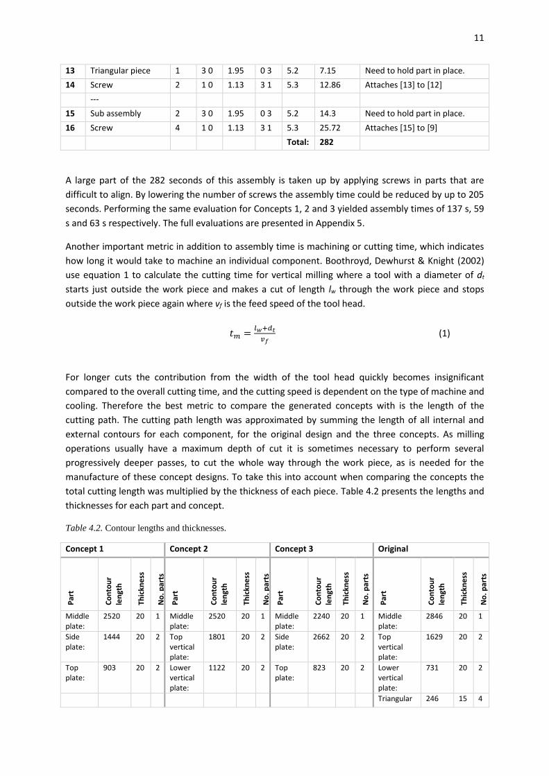
total cutting length was multiplied by the thickness of each piece. Table 4.2 presents the lengths and
thicknesses for each part and concept.
Table 4.2. Contour lengths and thicknesses.
Concept 1 Concept 2 Concept 3 Original
Par
t
Co
nto
ur
len
gth
Thic
kne
ss
No
. par
ts
Par
t
Co
nto
ur
len
gth
Thic
kne
ss
No
. par
ts
Par
t
Co
nto
ur
len
gth
Thic
kne
ss
No
. par
ts
Par
t
Co
nto
ur
len
gth
Thic
kne
ss
No
. par
ts
Middle plate:
2520 20 1 Middle plate:
2520 20 1 Middle plate:
2240 20 1 Middle plate:
2846 20 1
Side plate:
1444 20 2 Top vertical plate:
1801 20 2 Side plate:
2662 20 2 Top vertical plate:
1629 20 2
Top plate:
903 20 2 Lower vertical plate:
1122 20 2 Top plate:
823 20 2 Lower vertical plate:
731 20 2
Triangular 246 15 4
𝑡𝑚 =𝑙𝑤+𝑑𝑡
𝑣𝑓 (1)
12
piece:
Top plate: 770 15 1
Upper axle attachment:
284 15 2
Tota
l
: 73
14
Tota
l
: 84
66
Tota
l
: 93
10
Tota
l
: 10
09
3
4.3 Screening of concept designs
To determine how well the new concepts met the criteria presented in the problem description they
had to be quantified and compared in a systematic way. The Pugh concept screening matrix as
described in Ulrich & Eppinger (2008) is a suitable way of comparing concepts that ranks them in
relation to each other. The matrix is made up of a column for each concept to be evaluated and a
row for each metric that is to be compared. One concept is chosen as the starting point for
comparison and all the others are compared relative to this concept, then for each metric listed on
the left hand side of the matrix the others are either rated better or worse in comparison. Finally the
score is tallied and one concept is chosen to proceed with, possibly by combining several strong
points from several concepts.
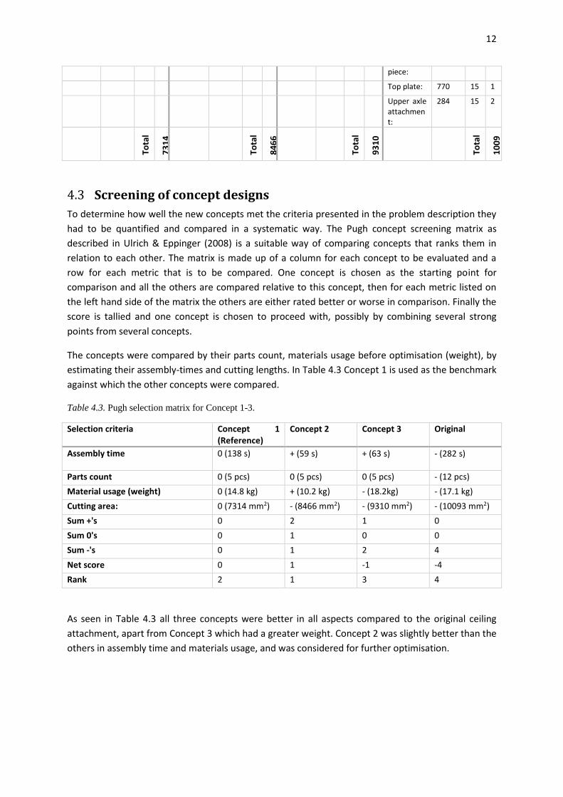
The concepts were compared by their parts count, materials usage before optimisation (weight), by
estimating their assembly-times and cutting lengths. In Table 4.3 Concept 1 is used as the benchmark
against which the other concepts were compared.
Table 4.3. Pugh selection matrix for Concept 1-3.
Selection criteria Concept 1 (Reference)
Concept 2 Concept 3 Original
Assembly time 0 (138 s) + (59 s) + (63 s) - (282 s)
Parts count 0 (5 pcs) 0 (5 pcs) 0 (5 pcs) - (12 pcs)
Material usage (weight) 0 (14.8 kg) + (10.2 kg) - (18.2kg) - (17.1 kg)
Cutting area: 0 (7314 mm2) - (8466 mm2) - (9310 mm2) - (10093 mm2)
Sum +'s 0 2 1 0
Sum 0's 0 1 0 0
Sum -'s 0 1 2 4
Net score 0 1 -1 -4
Rank 2 1 3 4
As seen in Table 4.3 all three concepts were better in all aspects compared to the original ceiling
attachment, apart from Concept 3 which had a greater weight. Concept 2 was slightly better than the
others in assembly time and materials usage, and was considered for further optimisation.
13
Figure 5.1. Factor of safety of Concept 2 after
thickness optimisation.
Optimisation of the selected concept design Optimising mechanical components and structures has historically been a very laborious task, given
the fact that optimising requires both extensive experience to determine when a design is optimal
and a large amount of calculation.
The optimisation process consists of several steps. Firstly, the design variables, the cost function to
be minimised and any constraints that must be satisfied are identified. Information to describe the
detail to be optimised is collected and the initial design is estimated. Following the initial steps the
iterative optimisation begins; which means analysing the part, checking the constraints, and
determining if the current design is optimal. If the design is not optimal it needs to be changed
according to some optimisation method and analysed again (Arora, 2004).
Structural optimisation methods are commonly divided into three types; size optimisation, shape
optimisation and topology optimisation (Lövgren & Norberg, 2011). Of these three methods size
optimisation and topology optimisation were used for optimising the concept chosen in section 4.3.
5.1 Size optimisation
Size optimisation encompasses determining the optimal size of some dimension in a structure, such
as thickness, to meet the cost function and constraints (Lövgren & Norberg, 2011). This can be
performed either by determining a function which returns the required dimension as a function of
the constraints and loading case or by an iterative process where the dimension is modified and the
system is analysed until an adequate result is obtained.
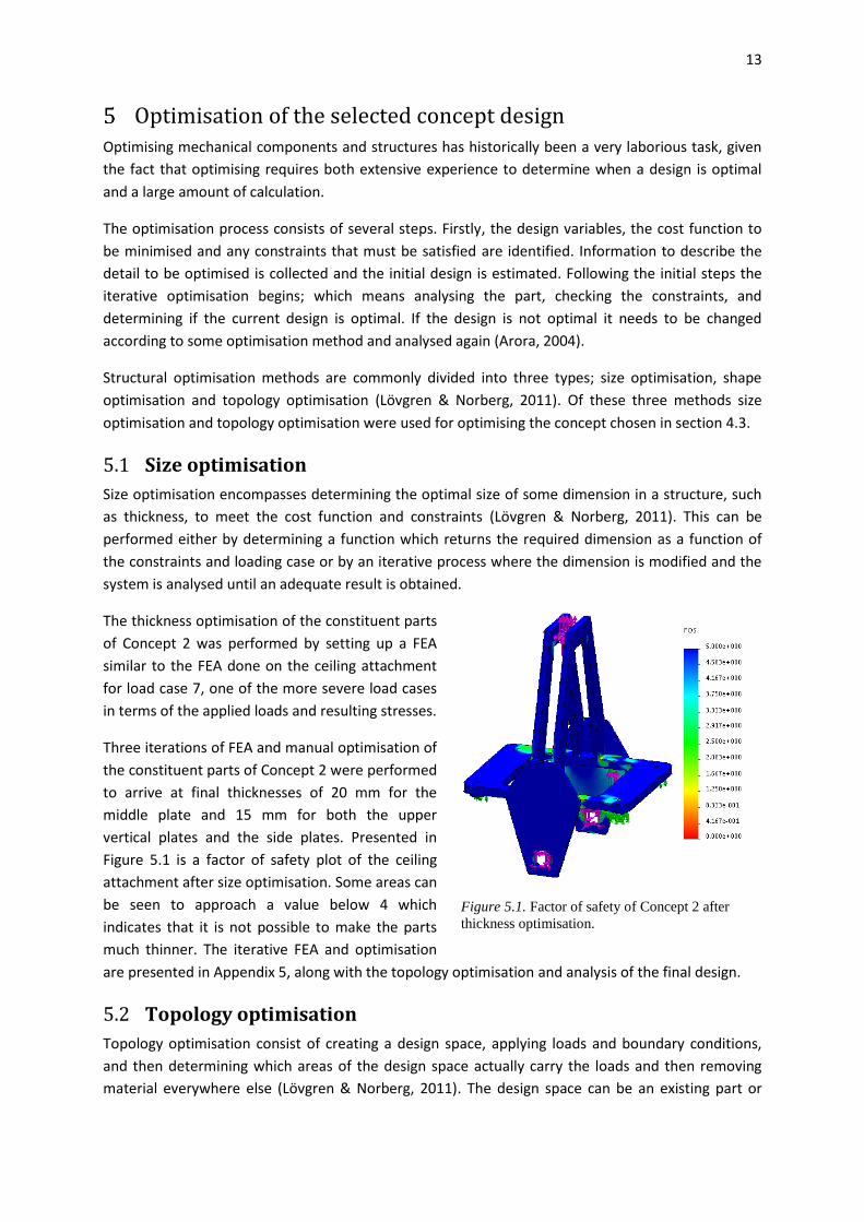
The thickness optimisation of the constituent parts
of Concept 2 was performed by setting up a FEA
similar to the FEA done on the ceiling attachment
for load case 7, one of the more severe load cases
in terms of the applied loads and resulting stresses.
Three iterations of FEA and manual optimisation of
the constituent parts of Concept 2 were performed
to arrive at final thicknesses of 20 mm for the
middle plate and 15 mm for both the upper
vertical plates and the side plates. Presented in
Figure 5.1 is a factor of safety plot of the ceiling
attachment after size optimisation. Some areas can
be seen to approach a value below 4 which
indicates that it is not possible to make the parts
much thinner. The iterative FEA and optimisation
are presented in Appendix 5, along with the topology optimisation and analysis of the final design.
5.2 Topology optimisation
Topology optimisation consist of creating a design space, applying loads and boundary conditions,
and then determining which areas of the design space actually carry the loads and then removing
material everywhere else (Lövgren & Norberg, 2011). The design space can be an existing part or

14
system from which material is removed to create a lighter structure. Alternatively it can be defined
as a space which is larger than needed while still satisfying any boundary conditions, when a new
optimal shape which might differ significantly from a previous design is to be found. This latter case
often results in organic-looking structures where only needed load paths are present.
Following the size optimisation of Concept 2, a rudimentary topology optimisation was performed to
remove some of the most superfluous material. Load cases 7 and 2 were used to identify load paths
in the model, otherwise the FEA performed was identical to those used for thickness optimisation.
Two iterations of FEA and material removal were performed.
In Figure 5.3, large areas can be seen where stresses are below 15 MPa. These areas were
subsequently cut out to yield the model in Figure 5.2. This model was then analysed and optimised a
second time, where it was found that the upper portion of the side plates was largely unloaded,
which resulted in a shortening of that part.
Figure 5.3. Iso-cutout showing areas with stresses
greater than 15 MPa for load case 7.
Figure 5.2. Result of removing material in
the first iteration of topology optimisation.
15
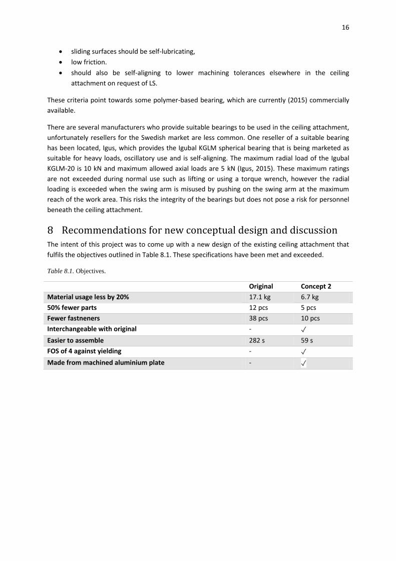
Figure 6.2. FOS for the final model for load case 7.
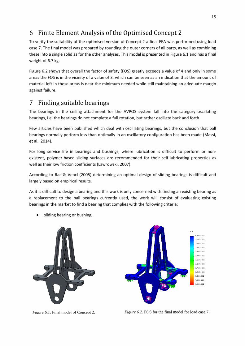
Finite Element Analysis of the Optimised Concept 2 To verify the suitability of the optimised version of Concept 2 a final FEA was performed using load
case 7. The final model was prepared by rounding the outer corners of all parts, as well as combining
these into a single solid as for the other analyses. This model is presented in Figure 6.1 and has a final
weight of 6.7 kg.
Figure 6.2 shows that overall the factor of safety (FOS) greatly exceeds a value of 4 and only in some
areas the FOS is in the vicinity of a value of 3, which can be seen as an indication that the amount of
material left in those areas is near the minimum needed while still maintaining an adequate margin
against failure.
Finding suitable bearings The bearings in the ceiling attachment for the AVPOS system fall into the category oscillating
bearings, i.e. the bearings do not complete a full rotation, but rather oscillate back and forth.
Few articles have been published which deal with oscillating bearings, but the conclusion that ball
bearings normally perform less than optimally in an oscillatory configuration has been made (Massi,
et al., 2014).
For long service life in bearings and bushings, where lubrication is difficult to perform or non-
existent, polymer-based sliding surfaces are recommended for their self-lubricating properties as
well as their low friction coefficients (Lawrowski, 2007).
According to Rac & Vencl (2005) determining an optimal design of sliding bearings is difficult and
largely based on empirical results.
As it is difficult to design a bearing and this work is only concerned with finding an existing bearing as
a replacement to the ball bearings currently used, the work will consist of evaluating existing
bearings in the market to find a bearing that complies with the following criteria:
sliding bearing or bushing,
Figure 6.1. Final model of Concept 2.
16
sliding surfaces should be self-lubricating,
low friction.
should also be self-aligning to lower machining tolerances elsewhere in the ceiling
attachment on request of LS.
These criteria point towards some polymer-based bearing, which are currently (2015) commercially
available.
There are several manufacturers who provide suitable bearings to be used in the ceiling attachment,
unfortunately resellers for the Swedish market are less common. One reseller of a suitable bearing
has been located, Igus, which provides the Igubal KGLM spherical bearing that is being marketed as
suitable for heavy loads, oscillatory use and is self-aligning. The maximum radial load of the Igubal
KGLM-20 is 10 kN and maximum allowed axial loads are 5 kN (Igus, 2015). These maximum ratings
are not exceeded during normal use such as lifting or using a torque wrench, however the radial
loading is exceeded when the swing arm is misused by pushing on the swing arm at the maximum
reach of the work area. This risks the integrity of the bearings but does not pose a risk for personnel
beneath the ceiling attachment.
Recommendations for new conceptual design and discussion The intent of this project was to come up with a new design of the existing ceiling attachment that
fulfils the objectives outlined in Table 8.1. These specifications have been met and exceeded.
Table 8.1. Objectives.
Original Concept 2
Material usage less by 20% 17.1 kg 6.7 kg
50% fewer parts 12 pcs 5 pcs
Fewer fastneners 38 pcs 10 pcs
Interchangeable with original - ✓
Easier to assemble 282 s 59 s
FOS of 4 against yielding - ✓
Made from machined aluminium plate - ✓

17
Figure 8.2. Completed redesign of
Concept 2 mounted on the swing arm.
To allow the parts with square corners to be inserted into each other the inner corners had to be
modified to allow regular milling techniques to be used. In Figure 8.1 the rounded reliefs, at the
corners of the slots cut in the side plate, can be seen. These reliefs are necessary as the milling tool
would otherwise leave a corner radius inside the slot, preventing the square tab from being inserted.
This also allows milling of all parts as flat two dimensional structures, as they do not need to be
milled from more than one direction to create tabs that can fit into rounded corners.
By switching the original ceiling attachment with the optimised version of Concept 2 in the assembly
model of the swing arm it was verified to be compatible as seen in Figure 8.2.
As this project dealt mainly with iterative optimisation and FEA as the means of arriving at a
conclusion the main sources of error are the same as for any FEA, namely boundary conditions and
loads, discretisation and the methods used for solving the stiffness matrix.
The boundary conditions for all analyses were applied to raised puck shapes which were not present
in the physical model of the ceiling attachment. This allowed for applying the boundary conditions to
a smaller surface than otherwise would have been possible, as well as letting out-of-plane flexing to
occur. One of the surfaces was fixed while the remaining three were constrained from out-of-plane
movement. This caused the fixed puck-shape to experience torsion and gave rise to stresses which
likely would not be present in the physical object being constrained by bolts to a stiff beam. As these
stresses did not propagate far into the model they could safely be ignored. The largest source of
error in terms of boundary conditions is the fact that the model was treated as a single solid, instead
of individual parts. This gave rise to tensile stresses in some interfaces which would normally be
pulled apart.
The load cases were previously determined in 2014 (Lindell) and were considered as the worst case
scenarios that the ceiling attachment would ever experience, especially in load case 7 which
contained the largest forces. This in conjunction with a factor of safety value of 4 gives a high
confidence that the structure will not yield.
The automatic meshing method used created a fairly coarse tetrahedral mesh, which saves on
Figure 8.1. Close-up of milled slots.

18
computations but could have large errors (Ottosen & Petersson, 1992). As the solution method
automatically refined the size of the elements according to an element-based error estimate this
issue was resolved.
Conclusions By creating a new design which uses less material and is easier to manufacture Löfs Specialmaskiner
can increase profit margins or lower the cost of the system to the customer. With a clearly defined
safety margin users can feel safe in not having the system fail in a dangerous manner and with lower
materials usage the environment is put under less strain.
References Arbetsmiljöverket. (2006, November 28). AFS 2006:6 - Användning av lyftanordningar och
lyftredskap. Sweden.
Arbetsmiljöverket. (2012). AFS 2012:02 - Belastningsergonomi. Stockholm, Sweden.
Arora, J. (2004). Introduction to optimum design. 2-7. San Diego, USA: Elsevier.
Atlas Copco. (2015). Atlas Copco torque arms. Retrieved January 01, 2015, from
http://194.132.104.143/websites/tools/Publications/acc11.nsf/va_TechLang/4511D2D28ED6
10A3C12579530048E714/$File/TorqueArms_US.pdf
Bogue, R. (2012). Design for manufacture and assembly: background, capabilities and applications.
Assembly Automation, 32(2), 112-118.
Boothroyd, G., Dewhurst, P., & Knight, W. (2002). Product Design for Manufacture and Assembly. 99-
141. New York: Marcel Dekker, Inc.
Dassault Systèmes. (2015, May 15). 2014 SOLIDWORKS Help - Analysis Solvers. Retrieved from
http://help.solidworks.com/2014/English/SolidWorks/cworks/c_Analysis_Solvers.htm
Emery, K., & Côté, J. N. (2012, February). Repetitive arm motion-induced fatigue affects shoulder but
not endpoint position sense. Experimental Brain Research, 216(4), 553-564.
Environmental and Health Aspects Related to the Production of Aluminium. (1994). Science of The
Total Environment. Oslo: The National Institute of Occupational Health. doi:10.1016/0048-
9697(95)90270-8
Forsström, A. (2010, 08 08). Utbrett barnarbete i Sverige under 1800-talet - DN.SE. Retrieved January
20, 2015, from Dagens Nyheter: http://www.dn.se/nyheter/vetenskap/utbrett-barnarbete-i-
sverige-under-1800-talet/
Givens Engineering Inc. (2011). Givens Engineering Inc. Retrieved January 1, 2015, from
http://www.giveng.com/TorqueArms.php
Igus. (2015). igus(R) igubal(R)-spherical bearings - KGLM. Retrieved from
http://www.igus.co.uk/wpck/2493/igubal_Gelenklager_KGLM_mm?C=GB&L=en
19
Kumar, V., & Gill, K. D. (2009, November). Aluminium neurotoxicity: neurobehavioural and oxidative
aspects. Archives of Toxicology, 83(11), 965-978. Retrieved March 03, 2015
Lawrowski, Z. (2007). Polymers in the construction of serviceless sliding bearings. Archives of civil and
mechanical engineering, VII, 139-150.
Lindell, I. (2014). Load cases for analysis of AVPOS. Högskolan i Skövde, Department of Engineering
Science.
Löfs Specialmaskiner AB. (2013). Lifting device for use at a manual work station. Swedish patent
application: 1330102-3.
Löfs Specialmaskiner AB. (2014a). Företagspresentation. Tibro, Sweden.
Löfs Specialmaskiner AB. (2014b). Meeting at Löfs Specialmaskiner. Tibro, Sweden.
Lövgren, S., & Norberg, E. (2011). Topology optimization of vehicle body structure for improved ride &
handling. Masters thesis. Sweden: Linköpings Universitet.
Massi, F., Bouscharain, N., Milana, S., Le Jeune, G., Maheo, Y., & Berthier, Y. (2014). Degradation of
high loaded oscillating bearings: Numerical analysis and comparison with experimental
observations. Wear, 317(1-2), 141-152.
Ottosen, N., & Petersson, H. (1992). Introduction to the finite element method. Prentice Hall.
Rac, A., & Vencl, A. (2005). Tribological and design parameters of lubricated sliding bearings.
Tribology in Industry, 27, 12-16.
Sundström, B. (1998). Handbok och formelsamling i Hållfasthetslära.
Ulrich, K. T., & Eppinger, S. D. (2008). Product design and development. 130-133. New York: McGraw-
Hill.
Venning, A. (2010, September 17). Britain's child slaves: New book says their misery helped forge
Britain. Retrieved January 20, 2015, from Mail Online:
http://www.dailymail.co.uk/news/article-1312764/Britains-child-slaves-New-book-says-
misery-helped-forge-Britain.html
Appendix 1 - 1
Appendix 1 - Division of labour All of the work performed in the main body of the thesis Optimisation of ceiling attachment for
AVPOS using FEA as well as the accompanying appendices 1, 2, 4, 5, and 6 has been done by Mikael
Koskenranta.
The contents of Appendix 3, Load cases, were contributed by Ida Lindell in 2014.
Appendix 2 - 1
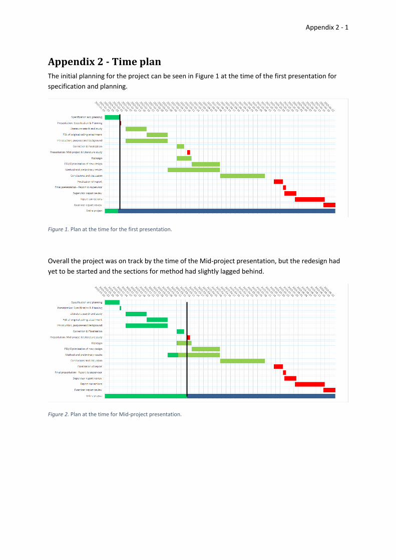
Appendix 2 - Time plan The initial planning for the project can be seen in Figure 1 at the time of the first presentation for
specification and planning.
Figure 1. Plan at the time for the first presentation.
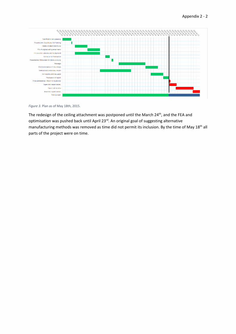
Overall the project was on track by the time of the Mid-project presentation, but the redesign had
yet to be started and the sections for method had slightly lagged behind.
Figure 2. Plan at the time for Mid-project presentation.
Appendix 2 - 2
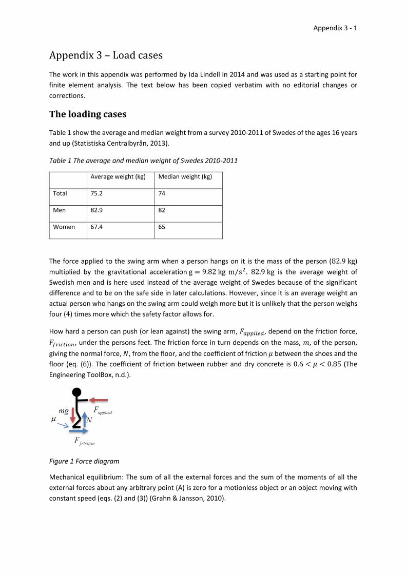
Figure 3. Plan as of May 18th, 2015.
The redesign of the ceiling attachment was postponed until the March 24th, and the FEA and
optimisation was pushed back until April 23rd. An original goal of suggesting alternative
manufacturing methods was removed as time did not permit its inclusion. By the time of May 18th all
parts of the project were on time.
Appendix 3 - 1
Appendix 3 – Load cases
The work in this appendix was performed by Ida Lindell in 2014 and was used as a starting point for
finite element analysis. The text below has been copied verbatim with no editorial changes or
corrections.
The loading cases
Table 1 show the average and median weight from a survey 2010-2011 of Swedes of the ages 16 years
and up (Statistiska Centralbyrån, 2013).
Table 1 The average and median weight of Swedes 2010-2011
Average weight (kg) Median weight (kg)
Total 75.2 74
Men 82.9 82
Women 67.4 65
The force applied to the swing arm when a person hangs on it is the mass of the person (82.9 kg)
multiplied by the gravitational acceleration g = 9.82 kg m s2⁄ . 82.9 kg is the average weight of
Swedish men and is here used instead of the average weight of Swedes because of the significant
difference and to be on the safe side in later calculations. However, since it is an average weight an
actual person who hangs on the swing arm could weigh more but it is unlikely that the person weighs
four (4) times more which the safety factor allows for.
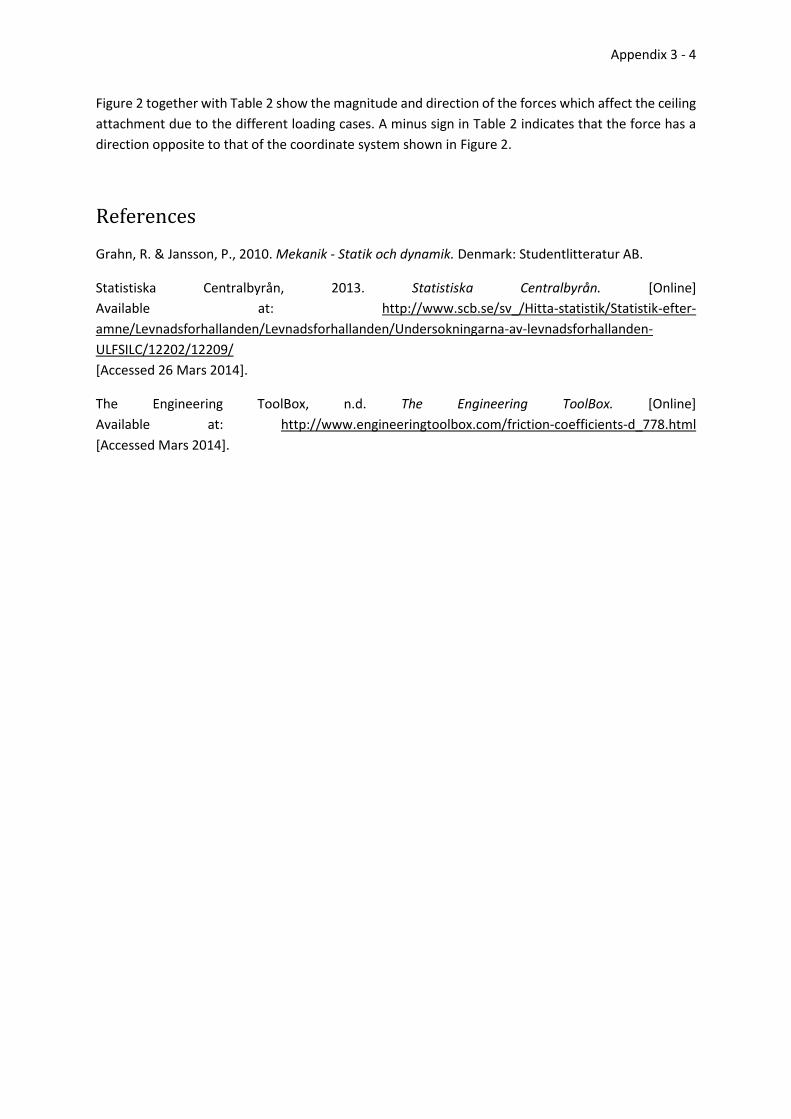
How hard a person can push (or lean against) the swing arm, 𝐹𝑎𝑝𝑝𝑙𝑖𝑒𝑑, depend on the friction force,
𝐹𝑓𝑟𝑖𝑐𝑡𝑖𝑜𝑛, under the persons feet. The friction force in turn depends on the mass, 𝑚, of the person,
giving the normal force, 𝑁, from the floor, and the coefficient of friction 𝜇 between the shoes and the
floor (eq. (6)). The coefficient of friction between rubber and dry concrete is 0.6 < 𝜇 < 0.85 (The
Engineering ToolBox, n.d.).
Figure 1 Force diagram
Mechanical equilibrium: The sum of all the external forces and the sum of the moments of all the
external forces about any arbitrary point (A) is zero for a motionless object or an object moving with
constant speed (eqs. (2) and (3)) (Grahn & Jansson, 2010).

Appendix 3 - 2
30
20
AM
F
Equilibrium equations from the force diagram in Figure 1 using eq. (2) divided vertically and
horizontally (eqs. (4) and (5)):
7
6&5,4
6
50:
40:
0
mgF
NF
FF
mgN
maF
applied
friction
appliedfriction
Choosing a high value for the coefficient of friction (𝜇 = 0.85), and thereby obtaining a large force, is
again a choice to be on the safe side in later calculations.
There are five contact points where forces affect
the ceiling attachment due to applied loadings and
the mass of the swing arm and of the cradle. Those
points are shown in Figure 2 and are indicated with
the letters A to E.
The weight of the swing arm is 43.8 kg and that of
the cradle is 4.6 kg, large enough to not be
insignificant, and needs to be accounted for. The
mass centre for the arm is located 675 mm
straight beneath the centre of the cradle when
hanging freely. When the swing arm is at an angle,
the pneumatic cylinder applies a force at the swing
arm and contact point A in Figure 2 to balance it
up. The force at the swing arm is transferred to the
ceiling attachment at points B and C. When AVPOS
is used as a lifting tool, the mass lifted is also
balanced with the pneumatic cylinder and the resulting forces affect the ceiling attachment at the
contact points A, B, and C.
There are thirteen (loading case 1-13) different loading cases shown in Table 2 which are calculated
using mechanical equilibrium (eqs. (2) and (3)). The loading cases are;
1. the swing arm hanging straight down without any applied load,
2. the swing arm hanging straight down with a person’s weight on it,
3. the swing arm hanging straight down with a person’s weight and a load of 20 kg on it,
4. the swing arm hanging straight down with an applied moment of 200 Nm,
5. an applied horizontal load in the positive x-direction from a person pushing on the lower end
of the swing arm,
Figure 2. Contact points where forces affect the ceiling attachment.

Appendix 3 - 3
6. an applied horizontal load in the positive x-direction from a person pushing on the lower end
of the swing arm and a load of 20 kg,
7. an applied moment of 200 Nm with the swing arm in the positive x-direction,
8. an applied horizontal load in the positive y-direction from a person pushing on the lower end
of the swing arm,
9. an applied horizontal load in the positive y-direction from a person pushing on the lower end
of the swing arm and a load of 20 kg,
10. an applied moment of 200 Nm with the swing arm in the positive y-direction,
11. an applied horizontal load in the positive x=y-direction from a person pushing on the lower
end of the swing arm,
12. an applied horizontal load in the positive x=y-direction from a person pushing on the lower
end of the swing arm and a load of 20 kg, and
13. an applied moment of 200 Nm with the swing arm in the positive x=y-direction.
Table 2 Forces that affect the ceiling attachment due to the different loading cases
A (x,y,z) [N] B (x,y,z) [N] C (x,y,z) [N] D (x,y,z) [N] E (x,y,z) [N]
1 0,0,0 0,0,-237.6 0,0,-237.6 0,0,0 0,0,0
2 0,0,0 0,0,-645.2 0,0,-645.2 0,0,0 0,0,0
3 0,0,0 0,0,-743.4 0,0,-743.4 0,0,0 0,0,0
4 0,0,0 0,-617.3,-237.6 0,617.3,-237.6 0,0,0 0,0,0
5 255.5,0,1975.6 0,0,-8977.2 437.3,0,6526.2 0,0,0 0,0,0
6 946.9,0,7320.9 -254.1,0,-11748 0,0,3755.4 0,0,0 0,0,0
7 255.5,0,1975.6 -255.5,-681.1,-1225.5 0,681.1,-1225.5 0,0,0 0,0,0
8 0,254.1,1964.3 0,219.35,-22871 0,219.35,-22871 0,0,21651.2 0,0,21651.2
9 0,945.5,7309.6 0,-126.4,-25641.9 0,-126.4,-25641.9 0,0,21651.2 0,0, 21651.2
10 0,254.1,1964.3 0,-686.5,-1480.7 0,432.4,-958.9 0,0,0 0,0,0
11 234.6,234.6,2012.9 0,127.6,-20376.5 255.3,127.6,-
10317.2 0,0,14102.7 0,0,14102.7
12 871.4,871.4,7476.3 -381.5,-190.8,-
23150.9 0,-190.8,-13202.6 0,0,14102.7 0,0,14102.7
13 234.6,234.6,2012.9 -234.6,-734.6,-1512.4 0,500,-975.8 0,0,0 0,0,0
Appendix 3 - 4
Figure 2 together with Table 2 show the magnitude and direction of the forces which affect the ceiling
attachment due to the different loading cases. A minus sign in Table 2 indicates that the force has a
direction opposite to that of the coordinate system shown in Figure 2.
References
Grahn, R. & Jansson, P., 2010. Mekanik - Statik och dynamik. Denmark: Studentlitteratur AB.
Statistiska Centralbyrån, 2013. Statistiska Centralbyrån. [Online]
Available at: http://www.scb.se/sv_/Hitta-statistik/Statistik-efter-
amne/Levnadsforhallanden/Levnadsforhallanden/Undersokningarna-av-levnadsforhallanden-
ULFSILC/12202/12209/
[Accessed 26 Mars 2014].
The Engineering ToolBox, n.d. The Engineering ToolBox. [Online]
Available at: http://www.engineeringtoolbox.com/friction-coefficients-d_778.html
[Accessed Mars 2014].

Appendix 4 - i
Appendix 4 – FEA of the original ceiling attachment
Contents Appendix 4 – FEA of the original ceiling attachment ............................................................................... i
Finite element analysis of original AVPOS ceiling attachment ........................................................ 1
1.1 Geometry of the ceiling attachment ....................................................................................... 1
1.2 Material properties ................................................................................................................. 2
1.3 Boundary conditions ............................................................................................................... 3
1.4 Results ..................................................................................................................................... 4
1.4.1 Load case 1 ...................................................................................................................... 5
1.4.2 Load case 2 ...................................................................................................................... 6
1.4.3 Load case 3 ...................................................................................................................... 7
1.4.4 Load case 4 ...................................................................................................................... 8
1.4.5 Load case 5 ...................................................................................................................... 9
1.4.6 Load case 6 .................................................................................................................... 10
1.4.7 Load case 7 .................................................................................................................... 11
1.4.8 Load case 8 .................................................................................................................... 12
References ..................................................................................................................................... 13

Appendix 4 - 1
Finite element analysis of original AVPOS ceiling attachment This FEA is performed to identify any structural problems that may exist in the original ceiling
attachment for the AVPOS system. Any shortcomings will then be addressed in the redesign of the
ceiling attachment.
The modelling and FEA is performed using Solidworks 2014 SP 2.0 with the Solidworks Simulation
plugin.
1.1 Geometry of the ceiling attachment
The ceiling attachment consists of 13 components joined together as a solid for the purpose of
analysis. The original ceiling attachment is seen in Figure 1.1; a simplified version for analysis is seen
in Figure 1.2, along with the small 2 mm fillets applied to all sharp inner corners to avoid singularities
in the simulation; and the major dimensions are shown in Figure 1.4.
The entire model was analysed and symmetry planes were avoided as forces in multiple directions
were present in most analyses, which makes symmetry unsuitable.
Solidworks automatic meshing was used based on an initial tetrahedral element size of 20 mm in
width. During the actual analysis automatic mesh refinement further reduced the elements in some
areas. The smallest elements after refinement was on the order of 1 mm.
Presented in Figure 1.3 is a typical convergence plot with the error plotted as a percentage. This
specific plot shows the convergence for load case 7, which is one of the most severe load cases in
terms of the applied loads and resulting stresses.
Figure 1.1. Original ceiling
attachment.
Figure 1.2. Simplified ceiling
attachment.
Figure 1.3. H-adaptive convergence
plot, load case 7.

Appendix 4 - 2
1.2 Material properties
The material used in the ceiling attachment is an aluminium alloy called Plancast Plus 5083(n) (Löfs
Specialmaskiner AB, 2014b),which is ductile and has a linear elastic region with the properties
outlined in Table 1.1. These properties were used in all FEA. Small deformations were assumed for
the analyses, as such the material behaves as linear elastic. If large deformations would have been
observed this would have been revised.
Table 1.1. Material properties of Plancast Plus 5083(n)
Yield strength: 1.25e+008
N/m2
Poisson's ratio: 0.33
Tensile
strength:
2.5e+008 N/m2 Mass density: 2660 kg/m3
Elastic
modulus:
6.9e+010 N/m2 Shear
modulus:
2.59e+010
N/m2
Figure 1.4. Geometry of the ceiling attachment. All dimensions in mm.
Appendix 4 - 3
Figure 1.5. Boundary conditions.
Figure 1.6. Load contact points. (Lindell, 2014)
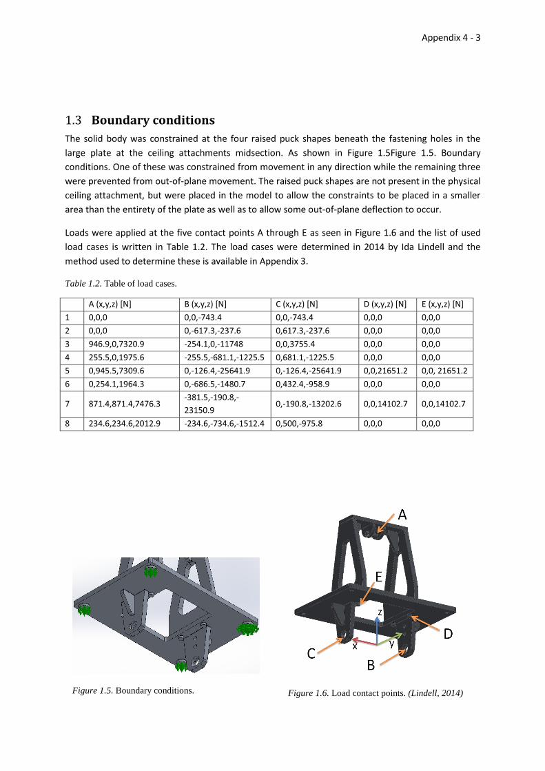
1.3 Boundary conditions
The solid body was constrained at the four raised puck shapes beneath the fastening holes in the
large plate at the ceiling attachments midsection. As shown in Figure 1.5Figure 1.5. Boundary
conditions. One of these was constrained from movement in any direction while the remaining three
were prevented from out-of-plane movement. The raised puck shapes are not present in the physical
ceiling attachment, but were placed in the model to allow the constraints to be placed in a smaller
area than the entirety of the plate as well as to allow some out-of-plane deflection to occur.
Loads were applied at the five contact points A through E as seen in Figure 1.6 and the list of used
load cases is written in Table 1.2. The load cases were determined in 2014 by Ida Lindell and the
method used to determine these is available in Appendix 3.
Table 1.2. Table of load cases.
A (x,y,z) [N] B (x,y,z) [N] C (x,y,z) [N] D (x,y,z) [N] E (x,y,z) [N]
1 0,0,0 0,0,-743.4 0,0,-743.4 0,0,0 0,0,0
2 0,0,0 0,-617.3,-237.6 0,617.3,-237.6 0,0,0 0,0,0
3 946.9,0,7320.9 -254.1,0,-11748 0,0,3755.4 0,0,0 0,0,0
4 255.5,0,1975.6 -255.5,-681.1,-1225.5 0,681.1,-1225.5 0,0,0 0,0,0
5 0,945.5,7309.6 0,-126.4,-25641.9 0,-126.4,-25641.9 0,0,21651.2 0,0, 21651.2
6 0,254.1,1964.3 0,-686.5,-1480.7 0,432.4,-958.9 0,0,0 0,0,0
7 871.4,871.4,7476.3 -381.5,-190.8,-
23150.9 0,-190.8,-13202.6 0,0,14102.7 0,0,14102.7
8 234.6,234.6,2012.9 -234.6,-734.6,-1512.4 0,500,-975.8 0,0,0 0,0,0

Appendix 4 - 4
1.4 Results
(Page intentionally left blank.)

Appendix 4 - 5
1.4.1 Load case 1
Number of elements: 392962 Maximum stress: 27.9 MPa Deformation scale:1196
Comment: A full load of
approximately 150 kg hanging
straight down.
Minimum factor of safety: 4.5
Appendix 4 - 6
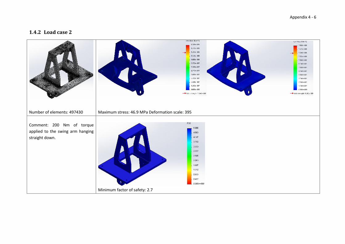
1.4.2 Load case 2
Number of elements: 497430 Maximum stress: 46.9 MPa Deformation scale: 395
Comment: 200 Nm of torque
applied to the swing arm hanging
straight down.
Minimum factor of safety: 2.7
Appendix 4 - 7
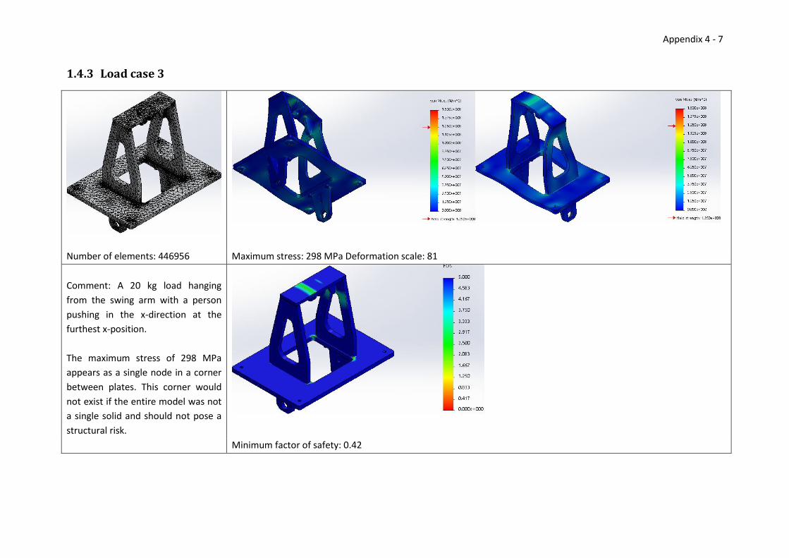
1.4.3 Load case 3
Number of elements: 446956 Maximum stress: 298 MPa Deformation scale: 81
Comment: A 20 kg load hanging
from the swing arm with a person
pushing in the x-direction at the
furthest x-position.
The maximum stress of 298 MPa
appears as a single node in a corner
between plates. This corner would
not exist if the entire model was not
a single solid and should not pose a
structural risk.
Minimum factor of safety: 0.42

Appendix 4 - 8
1.4.4 Load case 4
Number of elements: 434068 Maximum stress: 71 MPa Deformation scale: 155
Comment: 200 Nm of torque applied
to the swing arm at the furthest x-
position.
Minimum factor of safety: 1.8
Appendix 4 - 9
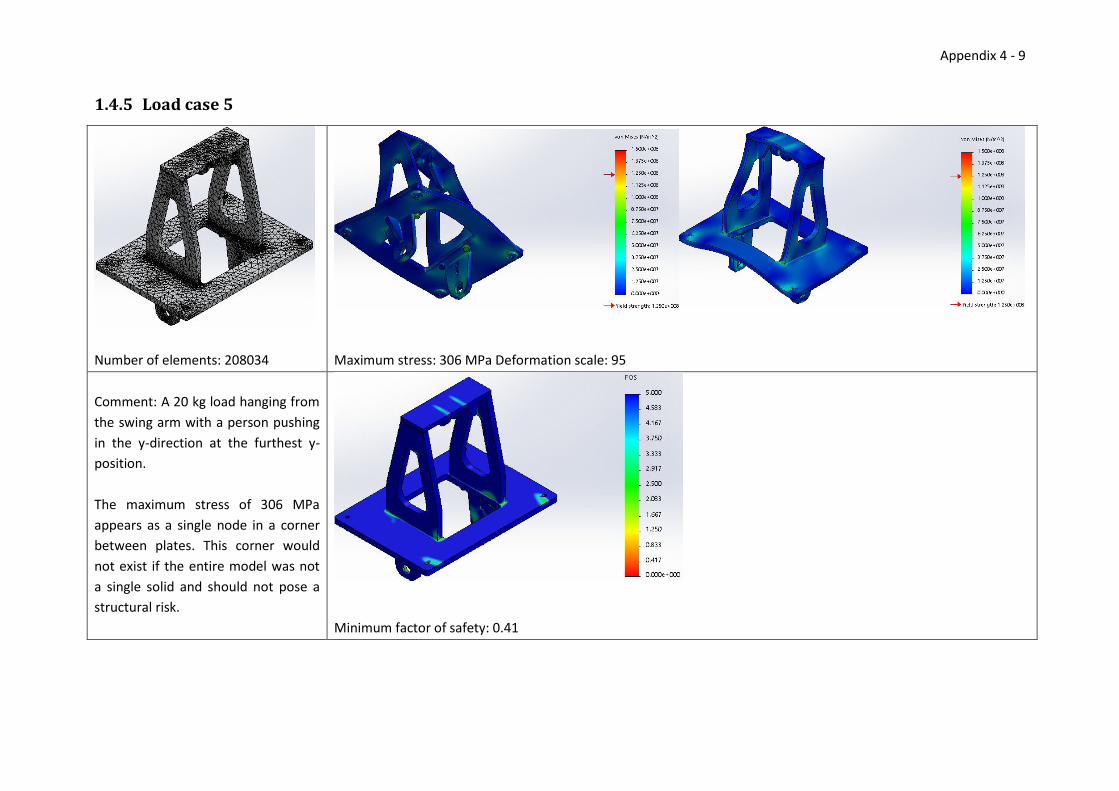
1.4.5 Load case 5
Number of elements: 208034 Maximum stress: 306 MPa Deformation scale: 95
Comment: A 20 kg load hanging from
the swing arm with a person pushing
in the y-direction at the furthest y-
position.
The maximum stress of 306 MPa
appears as a single node in a corner
between plates. This corner would
not exist if the entire model was not
a single solid and should not pose a
structural risk.
Minimum factor of safety: 0.41

Appendix 4 - 10
1.4.6 Load case 6
Number of elements: 289836 Maximum stress: 63.4 MPa Deformation scale: 190
Comment: 200 Nm of torque applied
to the swing arm at the furthest y-
position.
Minimum factor of safety: 2

Appendix 4 - 11
1.4.7 Load case 7
Number of elements: 357320 Maximum stress: 1509 MPa Deformation scale: 33
Comment: A 20 kg load hanging from
the swing arm with a person pushing
in the x and y-direction at the
furthest x and y-positions.
A maximum effective stress of 1509
MPa appears at several corners
which would not be present as a
single solid in the non-simplified
model, this likely does not pose a
structural risk but may lead to plastic
deformation.
Minimum factor of safety: 0.083
Appendix 4 - 12
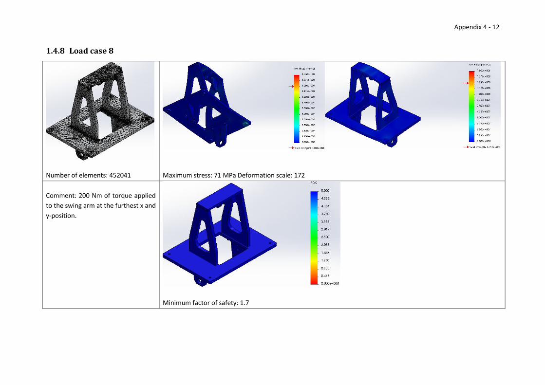
1.4.8 Load case 8
Number of elements: 452041 Maximum stress: 71 MPa Deformation scale: 172
Comment: 200 Nm of torque applied
to the swing arm at the furthest x and
y-position.
Minimum factor of safety: 1.7

Appendix 4 - 13
References Lindell, I. (2014). Load cases for analysis of AVPOS. Högskolan i Skövde.
Löfs Specialmaskiner AB. (2014b). Meeting at Löfs Specialmaskiner. Tibro, Sweden.

Appendix 5 - 1
Appendix 5 – Assembly Times In Tables 1, 2 and 3 the handling and insertion times can be read for each evaluation by reading the
handling and insertion codes from the evaluation table and looking up the corresponding row and
column. Tables 4, 5, 6 and 7 show the assembly times for the original design and the three concepts.
Table 1. Handling times for parts that can be manipulated with one hand. (Excerpt from (Boothroyd,
Dewhurst, & Knight, 2002))
No handling difficulties
Thickness > 2 mm
Symmetry (deg) = (alpha+beta) Size > 15 mm
Handling code (Row & Column)
0
sym < 360 0 1.13
360 <= sym < 540 1 1.5
540 <= sym < 720 2 1.8
sym = 720 3 1.95
Table 2. Insertion times for parts that are not immediately secured. (Excerpt from (Boothroyd, Dewhurst, &
Knight, 2002))
Secured by separate operation or part
No holding down required Holding down required
Easy to align Not easy to align
Easy to align Not easy to align
Insertion code
0 1 2 3
No access or vision difficulties
0 1.5 3 2.6 5.2
Obstructed acces or restricted vision
1 3.7 5.2 4.8 7.4
Table 3. Insertion times for screws. (Excerpt from (Boothroyd, Dewhurst, & Knight, 2002))
Easy to align
Not easy to align
Insertion code
0 1
No access or vision difficulties
3 3.6 5.3

Appendix 5 - 2
Assembly time evaluation for the original ceiling attachment
Table 4. Assembly times for the original design.
No
. of
item
s
RP
Han
dlin
g
cod
e
Han
dlin
g
tim
e T
H
Inse
rtio
n
cod
e
Inse
rtio
n
tim
e TI
Tota
l tim
e
RP
*(T
H+T
I) Comment
1 Top plate 1 0 0 1.13 0 0 1.5 2.63 First part
2 Attachment for top
axle
2 1 0 1.5 0 3 5.2 13.4 Need to hold part in place
3 Screw 6 1 0 1.13 3 1 5.3 38.58 Attaches [2] to [1]
4 Triangular piece 2 3 0 1.95 0 3 5.2 14.3 Need to hold part in place
5 Screw 4 1 0 1.13 3 1 5.3 25.72 Attaches [4] to [1]
6 Vertical side part 2 2 0 1.8 0 3 5.2 14 Need to hold part in place
7 Screw 4 1 0 1.13 3 1 5.3 25.72 Attaches [6] to [4]
8 Screw 6 1 0 1.13 3 1 5.3 38.58 Attaches [6] to [1]. Part aligned
from previous step.
9 Middle plate 1 2 0 1.8 0 3 5.2 7 Need to hold part in place
10 Screw 2 1 0 1.13 3 1 5.3 12.86 Attaches [9] to [6]
11 Screw 4 1 0 1.13 3 1 5.3 25.72 Attaches [9] to [6]. Part aligned
from previous step.
--- Sub assembly ---
12 Attachment for
lower axle
1 3 0 1.95 0 0 1.5 3.45 First part in sub assembly
13 Triangular piece 1 3 0 1.95 0 3 5.2 7.15 Need to hold part in place.
14 Screw 2 1 0 1.13 3 1 5.3 12.86 Attaches [13] to [12]
---
15 Sub assembly 2 3 0 1.95 0 3 5.2 14.3 Need to hold part in place.
16 Screw 4 1 0 1.13 3 1 5.3 25.72 Attaches [15] to [9]
Total: 281.99

Appendix 5 - 3
Assembly time evaluation for concept 1
Table 5. Assembly times for Concept 1.
No
. of
item
s R
P
Han
dlin
g co
de
Han
dlin
g ti
me
TH
Inse
rtio
n c
od
e
Inse
rtio
n t
ime
TI
Tota
l tim
e R
P*
(TH
+TI)
Comment
1 Base plate 1 0 0 1.13 0 0 1.5 2.63 First part
2 Side plate 2 1 0 1.5 0 2 2.6 8.2
3 Screw 4 1 1 1.8 3 1 5.3 28.4 Attaches [2] to [1]
4 Top plate 2 1 0 1.5 0 3 5.2 13.4
5 Screw 12 1 1 1.8 3 1 5.3 85.2 Attaches [4] to [2]
Total: 137.83
Assembly time evaluation for concept 2 Table 6. Assembly times for Concept 2.
No
. of
item
s R
P
Han
dlin
g co
de
Han
dlin
g ti
me
TH
Inse
rtio
n c
od
e
Inse
rtio
n t
ime
TI
Tota
l tim
e R
P*
(TH
+TI)
Comment
1 Base plate 1 0 0 1.13 0 0 1.5 2.63 First part
2 Side plate 1 1 1 0 1.5 0 2 2.6 4.1
3 Screw 2 1 1 1.8 3 0 3.6 10.8 Attaches [2] to [1]
4 Top vertical plate 2 1 0 1.5 0 0 1.5 6
5 Screw 2 1 1 1.8 3 0 3.6 10.8 Attaches [4] to [2]
6 Side plate 2 1 1 0 1.5 0 0 1.5 3
7 Screw 4 1 1 1.8 3 0 3.6 21.6 Attaches [6] to [1] and [4]
Total: 58.93
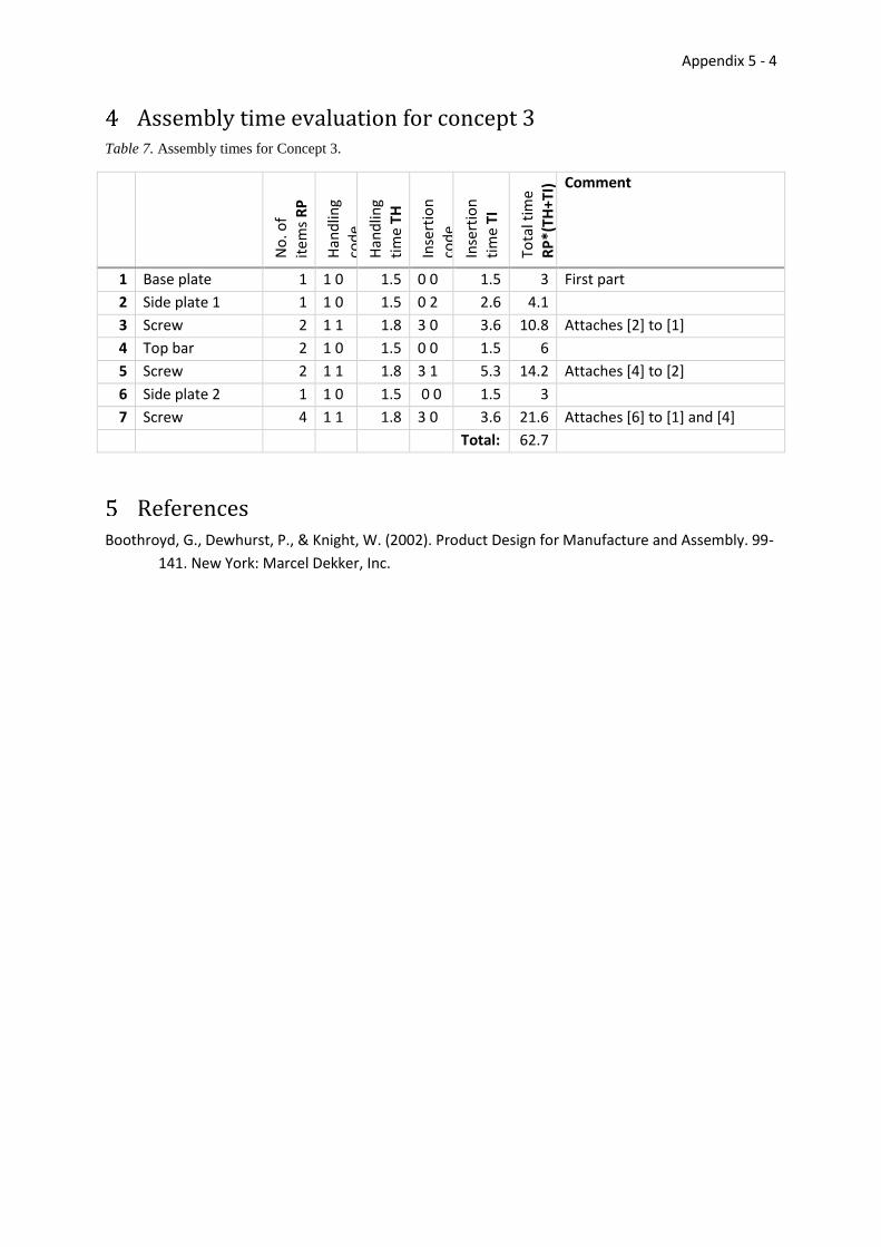
Appendix 5 - 4
Assembly time evaluation for concept 3 Table 7. Assembly times for Concept 3.
No
. of
item
s R
P
Han
dlin
g
cod
e
Han
dlin
g ti
me
TH
Inse
rtio
n
cod
e
Inse
rtio
n
tim
e TI
Tota
l tim
e R
P*
(TH
+TI)
Comment
1 Base plate 1 1 0 1.5 0 0 1.5 3 First part
2 Side plate 1 1 1 0 1.5 0 2 2.6 4.1
3 Screw 2 1 1 1.8 3 0 3.6 10.8 Attaches [2] to [1]
4 Top bar 2 1 0 1.5 0 0 1.5 6
5 Screw 2 1 1 1.8 3 1 5.3 14.2 Attaches [4] to [2]
6 Side plate 2 1 1 0 1.5 0 0 1.5 3
7 Screw 4 1 1 1.8 3 0 3.6 21.6 Attaches [6] to [1] and [4]
Total: 62.7
References Boothroyd, G., Dewhurst, P., & Knight, W. (2002). Product Design for Manufacture and Assembly. 99-
141. New York: Marcel Dekker, Inc.

Appendix 6 - i
Appendix 6 – Iterative FEA and optimisation of Concept 2
Table of Contents
Contents Appendix 6 – Iterative FEA and optimisation of Concept 2 ..................................................................... i
Table of Contents ..................................................................................................................................... i
Iterative FEA and optimisation of Concept 2 .................................................................................. 1
1.1 Geometry of Concept 2 ........................................................................................................... 1
1.2 Material properties ................................................................................................................. 2
1.3 Boundary conditions ............................................................................................................... 2
1.4 Results ..................................................................................................................................... 4
1.4.1 First iteration of thickness optimisation ......................................................................... 5
1.4.2 Iteration 2 of thickness optimisation .............................................................................. 6
1.4.3 Iteration 3 of thickness optimisation .............................................................................. 7
1.4.4 First iteration of topology optimisation .......................................................................... 8
1.4.5 Iteration 2 of topology optimisation ............................................................................... 9
1.5 FEA of optimised model ........................................................................................................ 10
References ..................................................................................................................................... 11

Appendix 6 - 1
Iterative FEA and optimisation of Concept 2 This iterative FEA and optimisation was performed to first optimise the thickness of the constituent
parts and then to remove any unneeded material.
For thickness optimisation load case 7 was used as that was the load case with the highest observed
stresses in the original ceiling attachment. An initial FEA was performed where all the constituent
parts of Concept 2 had a thickness of 20 mm. Following that the thickness of each component was
decreased in increments of 5 mm until non-negligible areas of the components had a factor of safety
near a value of 4, at which point the thickness optimisation for that component was stopped.
For topology optimisation load case 7 and load case 2 were used to determine the behaviour of
Concept 2 both when it was loaded with large forces as well as when a torque was applied. First an
initial FEA was performed where the middle plate had a thickness of 20 mm and the side and top
plates had a thickness of 15 mm, as determined in the thickness optimisation.
The modelling and FEA is performed using Solidworks 2014 SP 2.0 with the Solidworks Simulation
plugin.
1.1 Geometry of Concept 2
Concept 2 consists of 6 components joined together as a solid for the purpose of analysis. Concept 2
prior to optimisation is presented in Figure 1.2 and a simplified version for analysis is seen in Figure
1.1, along with the small 2 mm fillets applied to all sharp inner corners to avoid singularities in the
simulation; and the major dimensions of the parts are shown in Figure 1.3.
The entire model was analysed and symmetry planes were avoided as forces in multiple directions
were present in the analyses, which makes symmetry unsuitable.
The mesh used for the analysis was a tetrahedral mesh, as other mesh types were not available in
Solidworks simulation for solid bodies. Initially the mesh was set to use elements smaller than 20 mm
in width, but as h-adaptive refinement was used for the analyses the final mesh used elements as
small as 1 mm in some areas.
Figure 1.2. Concept 2 prior to
optimisations.
Figure 1.1. Simplified version
of Concept 2 for FEA.

Appendix 6 - 2
Figure 1.4. Boundary conditions.
1.2 Material properties
The material used in the ceiling attachment is an aluminium alloy called Plancast Plus 5083(n) (Löfs
Specialmaskiner, 2014b), which is ductile and has a linear elastic region with the properties outlined
in Table 1.1. These properties were used in all FEA. Small deformations were assumed for the
analyses, as such the material behaves as linear elastic. If large deformations would have been
observed this would have been revised.
Table 1.1. Material properties of Plancast Plus 5083(n)
Yield strength: 1.25e+008
N/m2
Poisson's ratio: 0.33
Tensile
strength:
2.5e+008 N/m2 Mass density: 2660 kg/m3
Elastic
modulus:
6.9e+010 N/m2 Shear
modulus:
2.59e+010
N/m2
1.3 Boundary conditions
The solid body was constrained at the four raised puck shapes beneath the fastening holes in the
middle plate, as shown in Figure 1.4 One of these was constrained from movement in any direction
Figure 1.3. Geometry of Concept 2. All dimensions in mm.

Appendix 6 - 3
Figure 1.5. Load contact points.
while the remaining three were prevented from out-of-plane movement.
The raised puck shapes were placed in the model to allow the constraints to be placed in a smaller
area than the entirety of the plate as well as allow some out-of-plane deflection to occur.
Loads are applied at the five contact points A through E as seen in Figure 1.5 and the list of used load
cases is written in Table 1.2. The load cases were determined in 2014 by Ida Lindell and the method
used to determine these is available in Appendix 3.
Table 1.2. Table of load cases.
A (x,y,z) [N] B (x,y,z) [N] C (x,y,z) [N] D (x,y,z) [N] E (x,y,z) [N]
1 0,0,0 0,0,-743.4 0,0,-743.4 0,0,0 0,0,0
2 0,0,0 0,-617.3,-237.6 0,617.3,-237.6 0,0,0 0,0,0
3 946.9,0,7320.9 -254.1,0,-11748 0,0,3755.4 0,0,0 0,0,0
4 255.5,0,1975.6 -255.5,-681.1,-1225.5 0,681.1,-1225.5 0,0,0 0,0,0
5 0,945.5,7309.6 0,-126.4,-25641.9 0,-126.4,-25641.9 0,0,21651.2 0,0, 21651.2
6 0,254.1,1964.3 0,-686.5,-1480.7 0,432.4,-958.9 0,0,0 0,0,0
7 871.4,871.4,7476.3 -381.5,-190.8,-
23150.9 0,-190.8,-13202.6 0,0,14102.7 0,0,14102.7
8 234.6,234.6,2012.9 -234.6,-734.6,-1512.4 0,500,-975.8 0,0,0 0,0,0
Appendix 6 - 4
1.4 Results
(Page intentionally left blank.)

Appendix 6 - 5
1.4.1 First iteration of thickness optimisation
Number of elements: 217804 Maximum effective stress: 1583 MPa Deformation scale: 155
Comment: Comment: A 20 kg load hanging from
the swing arm with a person pushing in the x-
direction and y-direction at the furthest x and y-
position.
A few small spots with high stresses appear, but
these are all in corners that are not joined as a
single solid in the physical object.
The middle plate has some areas where the factor of
safety is around 4, as such the middle plate was not
made any thinner in further iterations.
Minimum factor of safety: 0.08
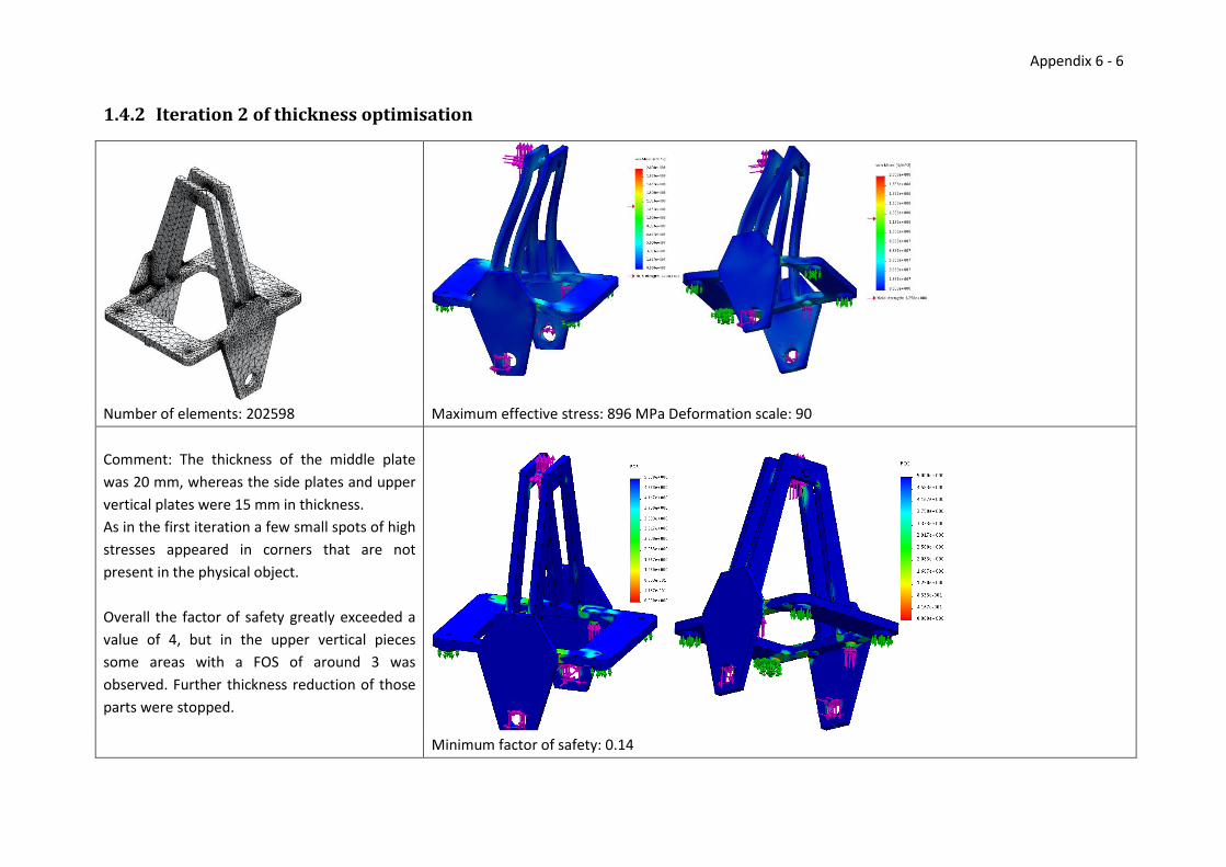
Appendix 6 - 6
1.4.2 Iteration 2 of thickness optimisation
Number of elements: 202598 Maximum effective stress: 896 MPa Deformation scale: 90
Comment: The thickness of the middle plate
was 20 mm, whereas the side plates and upper
vertical plates were 15 mm in thickness.
As in the first iteration a few small spots of high
stresses appeared in corners that are not
present in the physical object.
Overall the factor of safety greatly exceeded a
value of 4, but in the upper vertical pieces
some areas with a FOS of around 3 was
observed. Further thickness reduction of those
parts were stopped.
Minimum factor of safety: 0.14

Appendix 6 - 7
1.4.3 Iteration 3 of thickness optimisation
Number of elements: 213576 Maximum effective stress: 836 MPa Deformation scale: 93
Comment: The thickness of the components for this
iteration was 20 mm, 15 mm, and 10 mm for the
middle plate, the upper vertical plates and the side
plates respectively.
In the factor of safety plots large areas can be seen
where the FOS is near a value of 3. These areas were
deemed to be too large for comfort and the thickness
for the side plates was then set to 15 mm instead of the
10 mm in this FEA. With this the thickness optimisation
of the components was completed and topology
optimisation was initiated.
Minimum factor of safety: 0.15

Appendix 6 - 8
Figure 1.7. Areas with stresses above 15 MPa in
load case 7. Figure 1.6. Areas with stresses above 1 MPa
in load case 2.
1.4.4 First iteration of topology optimisation
Figure 1.8. Model after removing parts with low stresses.
Comment: For the first iteration of topology optimisation the model that had been thickness optimised was analysed using load case 2 and 7. Figure 1.6 and
Figure 1.7 show the areas which contain stresses of some significance. By removing parts of the areas which are not present in these two figures, while
taking symmetry into account the model in Figure 1.8 is obtained for the next iteration.
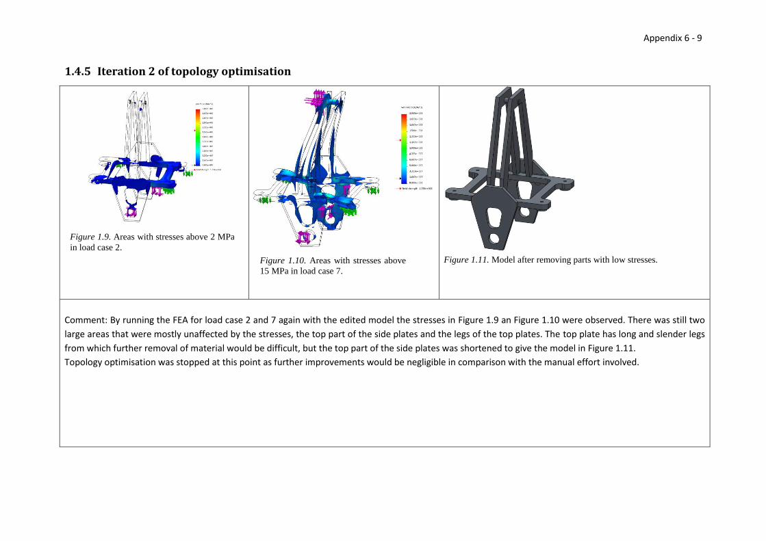
Appendix 6 - 9
Figure 1.10. Areas with stresses above
15 MPa in load case 7.
Figure 1.9. Areas with stresses above 2 MPa
in load case 2.
1.4.5 Iteration 2 of topology optimisation
Figure 1.11. Model after removing parts with low stresses.
Comment: By running the FEA for load case 2 and 7 again with the edited model the stresses in Figure 1.9 an Figure 1.10 were observed. There was still two
large areas that were mostly unaffected by the stresses, the top part of the side plates and the legs of the top plates. The top plate has long and slender legs
from which further removal of material would be difficult, but the top part of the side plates was shortened to give the model in Figure 1.11.
Topology optimisation was stopped at this point as further improvements would be negligible in comparison with the manual effort involved.
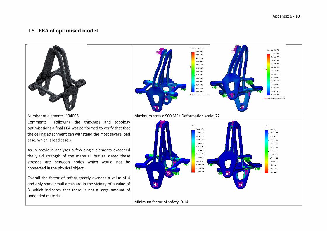
Appendix 6 - 10
1.5 FEA of optimised model
Number of elements: 194006 Maximum stress: 900 MPa Deformation scale: 72
Comment: Following the thickness and topology
optimisations a final FEA was performed to verify that that
the ceiling attachment can withstand the most severe load
case, which is load case 7.
As in previous analyses a few single elements exceeded
the yield strength of the material, but as stated these
stresses are between nodes which would not be
connected in the physical object.
Overall the factor of safety greatly exceeds a value of 4
and only some small areas are in the vicinity of a value of
3, which indicates that there is not a large amount of
unneeded material.
Minimum factor of safety: 0.14

Appendix 6 - 11
References Lindell, I. (2014). Load cases for analysis of AVPOS. Högskolan i Skövde, Department of Engineering Science.
Löfs Specialmaskiner AB. (2014b). Meeting at Löfs Specialmaskiner. Tibro, Sweden.