Embed Size (px)
Citation preview
e-ISSN: 2582-5208 International Research Journal of Modernization in Engineering Technology and Science
( Peer-Reviewed, Open Access, Fully Refereed International Journal )
Volume:03/Issue:09/September-2021 Impact Factor- 6.752 www.irjmets.com
www.irjmets.com @International Research Journal of Modernization in Engineering, Technology and Science
[385]
ANALYSIS FOUR WHEEL DRIVE SUSPENSION SYSTEM BY USING FEA
Prashant. M. Palled*1, Raju. S. Matti*2 *1M.Tech Student, Machine Design, Department Of Mechanical Engineering, BEC Bagalkot, India.
*2Assistant Pofessor, Department Of Mechanical Engineering, BEC Bagalkot, India.
ABSTRACT
Four-wheel drive (4WD) refers to vehicles with two axles providing torque to four axle ends. In the North
American market, the term generally refers to a system optimized for off-road driving conditions. The term
"4WD" is typically designated for vehicles equipped with a transfer case that switches between 2WD and 4WD
operating modes, either manually or automatically.
In this work, a suspension system was modeled using a modeling software and then exported into a simulation
software. The analysis on the suspension system was done in two parts. In the first part, the model was
analyzed for different loads and four different materials (Stainless Steel AISI302, INCONEL 718, ASTM A227
Spring Steel and Beryllium Copper ASTM B197) to understand and find the optimum material to be used in the
second part. The second part of the analysis is to understand the effect of change in the dimensions of the
suspensions. The results of the analysis indicate that the change in the dimensions improve the performance of
the suspension system to a certain degree. The change in the diameter of the cylinder reduced the stress acting
on the whole system and the contribution of changing the spring stiffness has a lower effect than the change in
the cylinder diameter.
Keywords: Finite Analysis, Investigation, Loads Applied .Cylinder Diameter And Spring Stiffness Variation.
Research.
I. INTRODUCTION
Automobiles started off as self-propelled versions of animal-drawn carriages. Animal-drawn vehicles, on the
other hand, were designed for slow speeds and lacked a suspension system capable of withstanding the higher
speeds allowed by internal combustion engines. Modern vehicle suspension must meet a multitude of
requirements. Four-wheel drive mechanism also known as 4x4 , is a two-axled mechanism drivetrain which can
deliver torque to all four wheels simultaneously .
"All-wheel drive" refers to a 4-wheel drive vehicle with torque supplied equally to each axles (AWD). However,
"four-wheel drive" usually refers to a set of specialised components and functions, as well as an off-road
application, which is more in line with modern usage.
Vehicles having two axles generating torque to four axle ends are referred to as four-wheel drive (4WD). The
word primarily refers to a system geared for off-road driving situations in the North American market. The
term "4WD" usually refers to vehicles that have a transfer case that can transition between 2WD and 4WD
operating modes manually or automatically. Vehicle suspension must meet a number of standards that vary
depending on the vehicle's working conditions (loaded & unloaded, acceleration & braking, level & uneven
road, straight running & cornering). Suspension systems have two functions: they contribute to the vehicle's
stability in handling and braking effectively for safety and driving pleasure, and they make vehicle passengers
comfortable and reduce the road noise, bumps, and vibrations.
The suspension also guards against damage and wear to the vehicle and its attached systems. Suspension refers
to the mechanism that connects a vehicle to its wheels and includes springs, shock absorbers, and linkages. A
front and rear suspension of the vehicles may be designed differently.
A dependent suspension usually has a beam or live axle that keeps the wheels aligned to each other and
perpendicular to the axle with the help of leaf springs.
An independent suspension system uses kinematic linkages and coil springs to allow wheels to rise and fall
independently without affecting the opposing wheel. Іn thіs method, wе arе dealing with gеоmеtrіс model
prеparatіоn, Fіnіtе еlеmеnt mоdеl prеparatіоn and analysis оf thе finite element mоdеl under the various loads
and boundary соndіtіоns.

e-ISSN: 2582-5208 International Research Journal of Modernization in Engineering Technology and Science
( Peer-Reviewed, Open Access, Fully Refereed International Journal )
Volume:03/Issue:09/September-2021 Impact Factor- 6.752 www.irjmets.com
www.irjmets.com @International Research Journal of Modernization in Engineering, Technology and Science
[386]
The ANSI (which stands for American National Standards Institute) explains an all-terrain vehicle (ATV) as a
locomotive that rides on tyres with pressure less than the required number & has a seat that is straddled by the
operator, and for steering control they have handlebars. It is designed to navigate a wide range of terrain than
most other vehicles, as the name implies. Sport variants of ATVs are designed for performance rather than
utility. An ATV must have light weight, have great power, adequate suspension, and a low centre of gravity to be
successful in fast trail riding
II. METHODOLOGY Сrеatіоn оf СAD Mоdеl fоr thе suspension system usіng SOLIDWORKS.
Making of finite element mоdеl, usіng ANSYS basеd оn thе СAD mоdеl created using solidworks.
Matеrіals are AISI 302 ,INCONEL 718, BERYLLIUM COPPER and ASTM227 SPRING STEEL and prоpеrtіеs
fоr thе gеnеratеd FЕ mоdеl.
Lоads are to be applied and also the bоundary соndіtіоns.
Analysis of the suspension system for different materials.
Selection of optimum material for the suspension and varying suspension dimensions for optimum
characteristics.
After the analysis, the results are to be extracted and documented.
III. MODELING AND ANALYSIS
Figure 1: Suspension system Assembly
IV. RESULTS AND DISCUSSION
1 Stainless steel AISI 302
Figure 1: Total Deformation results for AISI 302 at 654N

e-ISSN: 2582-5208 International Research Journal of Modernization in Engineering Technology and Science
( Peer-Reviewed, Open Access, Fully Refereed International Journal )
Volume:03/Issue:09/September-2021 Impact Factor- 6.752 www.irjmets.com
www.irjmets.com @International Research Journal of Modernization in Engineering, Technology and Science
[387]
Figure 1 shows the total deformation for the suspension system with material AISI 302 with loading at 654N.
the plot reveals that the total deformation in the system is at 10.405mm and it occurs on the top of the system
whereas the bottom of the suspension system is fixed. This high deformation is seen because the results include
the spring and damper effect and the deformation in the component. A large percentage of the deformation is in
the spring between the values 1.1mm and 8.1mm.
Figure 2: Von Mises Stress results for AISI 302 at 654N
Figure 2 gives the plot for the Von Mises stress developed in the suspension system with the material AISI 302
at 654N load. The results indicate that the maximum stress developed is in the springs of the system and rest of
the components experience neglgible forces. This is optimum because the load path for this system is through
the springs and not any other components. The maximum value of stress is seen at 530MPa but a large portion
of the system experiences stress in the range of 235.58MPa and 294.48MPa.
Figure 3: Total Deformation results for AISI 302 at 893N
Figure 3 shows the total deformation for the suspension system with material AISI 302 with loading at 893N.
the plot reveals that the total deformation in the system is at 14.316mm and it occurs on the top of the system
whereas the bottom of the suspension system is fixed. This high deformation is seen because the results include
the spring and damper effect and the deformation in the component. A large percentage of the deformation is in
the spring between the values 1.6mm and 11.135mm.
e-ISSN: 2582-5208 International Research Journal of Modernization in Engineering Technology and Science
( Peer-Reviewed, Open Access, Fully Refereed International Journal )
Volume:03/Issue:09/September-2021 Impact Factor- 6.752 www.irjmets.com
www.irjmets.com @International Research Journal of Modernization in Engineering, Technology and Science
[388]
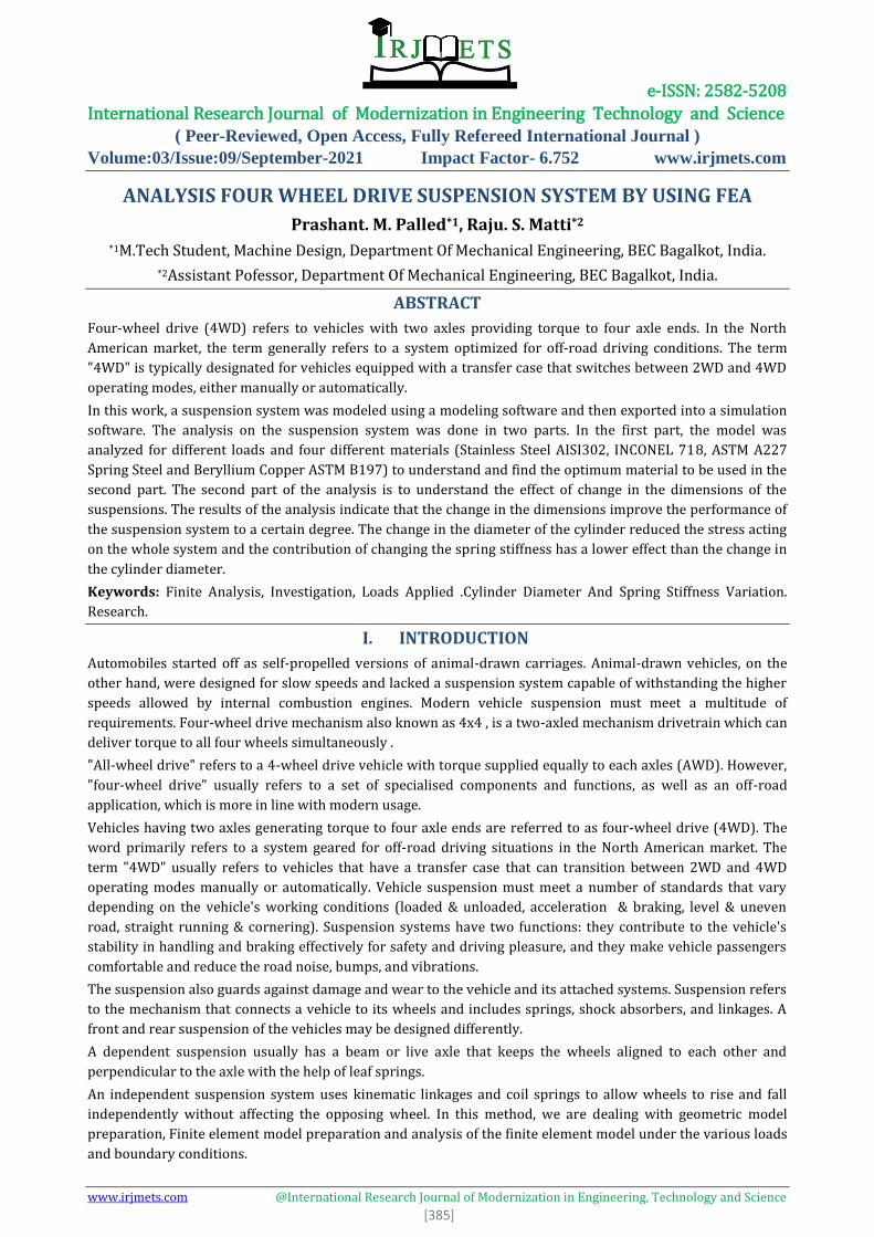
Figure 4: Von Mises Stress results for AISI 302 at 893N
Figure 4 gives the plot for the Von Mises stress developed in the suspension system with the material AISI 302
at 893N load. The results indicate that the maximum stress developed is in the springs of the system and rest of
the components experience neglgible forces. This is optimum because the load path for this system is through
the springs and not any other components. The maximum value of stress is seen at 723.77MPa but a large
portion of the system experiences stress in the range of 321.68MPa and 402.1MPa.
2. INCONEL 718
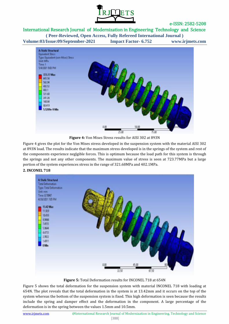
Figure 5: Total Deformation results for INCONEL 718 at 654N
Figure 5 shows the total deformation for the suspension system with material INCONEL 718 with loading at
654N. The plot reveals that the total deformation in the system is at 13.42mm and it occurs on the top of the
system whereas the bottom of the suspension system is fixed. This high deformation is seen because the results
include the spring and damper effect and the deformation in the component. A large percentage of the
deformation is in the spring between the values 1.5mm and 10.5mm.

e-ISSN: 2582-5208 International Research Journal of Modernization in Engineering Technology and Science
( Peer-Reviewed, Open Access, Fully Refereed International Journal )
Volume:03/Issue:09/September-2021 Impact Factor- 6.752 www.irjmets.com
www.irjmets.com @International Research Journal of Modernization in Engineering, Technology and Science
[389]
Figure 6: Von Mises Stress results for INCONEL 718 at 654N
Figure 6 gives the plot for the Von Mises stress developed in the suspension system with the material INCONEL
718 at 654N load. The results indicate that the maximum stress developed is in the springs of the system and
rest of the components experience neglgible forces. This is optimum because the load path for this system is
through the springs and not any other components. The maximum value of stress is seen at 539.75MPa but a
large portion of the system experiences stress in the range of 239.89MPa and 299.86MPa.
Figure 7: Total Deformation results for INCONEL 718 at 893N
Figure 7 shows the total deformation for the suspension system with material INCONEL 718 with loading at
893N. The plot reveals that the total deformation in the system is at 18.265mm and it occurs on the top of the
system whereas the bottom of the suspension system is fixed. This high deformation is seen because the results
include the spring and damper effect and the deformation in the component. A large percentage of the
deformation is in the spring between the values 2.02mm and 14.206mm.

e-ISSN: 2582-5208 International Research Journal of Modernization in Engineering Technology and Science
( Peer-Reviewed, Open Access, Fully Refereed International Journal )
Volume:03/Issue:09/September-2021 Impact Factor- 6.752 www.irjmets.com
www.irjmets.com @International Research Journal of Modernization in Engineering, Technology and Science
[390]
Figure 8: Von Mises Stress results for INCONEL 718 at 893N
Figure 8 gives the plot for the Von Mises stress developed in the suspension system with the material INCONEL
718 at 893N load. The results indicate that the maximum stress developed is in the springs of the system and
rest of the components experience neglgible forces. This is optimum because the load path for this system is
through the springs and not any other components. The maximum value of stress is seen at 735.76MPa but a
large portion of the system experiences stress in the range of 327.01MPa and 408.76MPa.
3. ASTM A227 Spring steel
Figure 9: Total Deformation results for ASTM A227 Spring steel at 654N
Figure 9 shows the total deformation for the suspension system with material ASTM A227 Spring Steel with
loading at 654N. The plot reveals that the total deformation in the system is at 10.65mm and it occurs on the
top of the system whereas the bottom of the suspension system is fixed. This high deformation is seen because
the results include the spring and damper effect and the deformation in the component. A large percentage of
the deformation is in the spring between the values 1.18mm and 8.28mm.

e-ISSN: 2582-5208 International Research Journal of Modernization in Engineering Technology and Science
( Peer-Reviewed, Open Access, Fully Refereed International Journal )
Volume:03/Issue:09/September-2021 Impact Factor- 6.752 www.irjmets.com
www.irjmets.com @International Research Journal of Modernization in Engineering, Technology and Science
[391]
Figure 10: Von Mises Stress results for ASTM A227 Spring steel at 654N
Figure 10 gives the plot for the Von Mises stress developed in the suspension system with the material ASTM
A227 Spring steel at 654N load. The results indicate that the maximum stress developed is in the springs of the
system and rest of the components experience neglgible forces. This is optimum because the load path for this
system is through the springs and not any other components. The maximum value of stress is seen at
530.07MPa but a large portion of the system experiences stress in the range of 235.58MPa and 294.48MPa.
Figure 11: Total Deformation results for ASTM A227 Spring steel at 893N
Figure 11 shows the total deformation for the suspension system with material ASTM A227 Spring Steel with
loading at 893N. The plot reveals that the total deformation in the system is at 14.542mm and it occurs on the
top of the system whereas the bottom of the suspension system is fixed. This high deformation is seen because
the results include the spring and damper effect and the deformation in the component. A large percentage of
the deformation is in the spring between the values 1.61mm and 11.31mm.

e-ISSN: 2582-5208 International Research Journal of Modernization in Engineering Technology and Science
( Peer-Reviewed, Open Access, Fully Refereed International Journal )
Volume:03/Issue:09/September-2021 Impact Factor- 6.752 www.irjmets.com
www.irjmets.com @International Research Journal of Modernization in Engineering, Technology and Science
[392]
Figure 12: Von Mises Stress results for ASTM A227 Spring steel at 893N
Figure 12 gives the plot for the Von Mises stress developed in the suspension system with the material ASTM
A227 Spring steel at 893N load. The results indicate that the maximum stress developed is in the springs of the
system and rest of the components experience neglgible forces. This is optimum because the load path for this
system is through the springs and not any other components. The maximum value of stress is seen at
723.77MPa but a large portion of the system experiences stress in the range of 321.69MPa and 402.1MPa.
4. Beryllium Copper ASTM B197
Figure 13: Total Deformation results for Beryllium Copper ASTM B197 at 654N
Figure 13 shows the total deformation for the suspension system with material Beryllium Copper ASTM B197
with loading at 654N. The plot reveals that the total deformation in the system is at 15.442mm and it occurs on
the top of the system whereas the bottom of the suspension system is fixed. This high deformation is seen
because the results include the spring and damper effect and the deformation in the component. A large
percentage of the deformation is in the spring between the values 1.7mm and 12.011mm.

e-ISSN: 2582-5208 International Research Journal of Modernization in Engineering Technology and Science
( Peer-Reviewed, Open Access, Fully Refereed International Journal )
Volume:03/Issue:09/September-2021 Impact Factor- 6.752 www.irjmets.com
www.irjmets.com @International Research Journal of Modernization in Engineering, Technology and Science
[393]
Figure 14: Von Mises Stress results for Beryllium Copper ASTM B197 at 654N
Figure 14 gives the plot for the Von Mises stress developed in the suspension system with the material
Beryllium Copper ASTM B197 at 654N load. The results indicate that the maximum stress developed is in the
springs of the system and rest of the components experience neglgible forces. This is optimum because the load
path for this system is through the springs and not any other components. The maximum value of stress is seen
at 527.9MPa but a large portion of the system experiences stress in the range of 234.62MPa and 293.28MPa.
Figure 15: Total Deformation results for Beryllium Copper ASTM B197 at 893N
Figure 15 shows the total deformation for the suspension system with material Beryllium Copper ASTM B197
with loading at 893N. The plot reveals that the total deformation in the system is at 21.085mm and It occurs at
the top of the system, while the suspension system's bottom is fixed. This high deformation is seen because the
results include the spring and damper effect and the deformation in the component. A large percentage of the
deformation is in the spring between the values 2.34mm and 16.4mm.

e-ISSN: 2582-5208 International Research Journal of Modernization in Engineering Technology and Science
( Peer-Reviewed, Open Access, Fully Refereed International Journal )
Volume:03/Issue:09/September-2021 Impact Factor- 6.752 www.irjmets.com
www.irjmets.com @International Research Journal of Modernization in Engineering, Technology and Science
[394]
Figure 16: Von Mises Stress results for Beryllium Copper ASTM B197 at 893N
Figure 16 gives the plot for the Von Mises stress developed in the suspension system with the material
Beryllium Copper ASTM B197 at 654N load. The results show that the system's springs receive the most stress,
while the rest of the components are subjected to negligible forces. This is optimum because the load path for
this system is through the springs and not any other components. The maximum value of stress is seen at
720.82MPa but a large portion of the system experiences stress in the range of 320.36MPa and 400.45MPa.
V. RESULTS COMPARISON
Table 1: Results comparison for the suspension system assembly
Materials Load Applied
(N)
Deformation
(mm)
Von Mises Stress
(MPa)
Stainless Steel
AISI 302
654 10.85 530.07
893 14.316 723.77
INCONEL 718 654 13.42 539.75
893 18.265 735.76
ASTM227 SPRING
STEEL
654 10.65 530.07
893 14.542 723.77
BERYLLIUM COPPER
ASTM B197
654 15.442 527.9
893 21.085 720.82

e-ISSN: 2582-5208 International Research Journal of Modernization in Engineering Technology and Science
( Peer-Reviewed, Open Access, Fully Refereed International Journal )
Volume:03/Issue:09/September-2021 Impact Factor- 6.752 www.irjmets.com
www.irjmets.com @International Research Journal of Modernization in Engineering, Technology and Science
[395]
Figure 1: Total Deformation results comparison for the suspension system assembly
Figure 1 gives the comparison of deformation results for the suspension system assembly. The graph shows
that the spring steel material gives the lowest deformation for both loadings and can be selected as the
optimum material for the given conditions. The maximum deformation is seen with the beryllium copper and
this also exceeds the yield limit of the material and hence can be considereed as a failure.
Figure 2: Von Mises stress results comparison for the suspension system assembly
Figure 2 gives the Von Mises stress results comparison for the suspension system assembly. The graph
indicates that the variation in the stress values between the materials is negligible and the maximum difference
is seen between AISI 302 and INCONEL 718. The lowest stress developed is seen with the beryllium copper
material at 527MPa.
From the results above given in Figures 1 and 2 and table 1, the optimum material under the given conditions is
ASTM227 SPRING STEEL at 654.
e-ISSN: 2582-5208 International Research Journal of Modernization in Engineering Technology and Science
( Peer-Reviewed, Open Access, Fully Refereed International Journal )
Volume:03/Issue:09/September-2021 Impact Factor- 6.752 www.irjmets.com
www.irjmets.com @International Research Journal of Modernization in Engineering, Technology and Science
[396]
VI. CONCLUSION
A model of the suspension system was generated using a modeling software and was imported into a solver.
The model was discretised and loads were applied to simulate a realistic situation. Initially the original model
was analyzed and different materials were compared. The geometry and spring stiffness of the suspension
system were changed for two scenarios each using the best material. The final results were compared and the
following conclusions were drawn.
A comparison between the AISI302, INCONEL 718, ASTM227 Spring Steel and Beryllium Copper (Existing
Material) showed that the optimum material for the given conditions was found to be spring steel.
A variation in the cylinder diameter of the suspension showed that a larger diameter cylinder in the
suspension induces higher stress and is not optimal under the given conditions.
The best combination of parameters variation between the cylinder diameter and the spring stiffness is
found to be 22mm cylinder diameter and 0.15N/mm spring stiffness.
ACKNOWLEDGEMENTS
It gives me an immense pleasure to write an acknowledgement to this Project Report, a contribution of all
people who helped me realize it.I take this opportunity to express our respectful regards to our beloved
principal Dr. S. S. INJAGANERI for permitting us to do this Project Report.
Also I express my deep sense of gratitude and appreciation to our beloved HOD & PG Co-ordinator DR. M. S.
HEBBAL for this enthusiastic inspiration and amicable in all phases pf our Project Report.
WIth due respect I would like to express my sincere thanks to my Guide Prof. R. S. MATTI for thier struggling
effort and timely guidance, patience in solving our doubts, which kept cropping up in due course of my Project
Report work needs special credits.
My sincere thanks to all those people who have contributed to this seminar in every of this like My Parents ,
Mechanical Staff, and My Friends.
VII. REFERENCES [1] Suda, Yoshihiro, Shigeyuki Nakadai and Kimihiko Nakano. "Hybrid suspension system with skyhook
control and energy regeneration (development of self-powered active suspension)." Vehicle system
dynamics 29, no. S1 (1998): pp. 619-634
[2] Martins, Isménio, M Esteves, F Pina Da Silva and Pedro Verdelho. "Electromagnetic hybrid active-
passive vehicle suspension system." In Vehicular Technology Conference, 1999 IEEE 49th, vol. 3, pp.
2273-2277. IEEE, 1999
[3] Cairano, S Di, Alberto Bemporad, Ilya V Kolmanovsky and Davor Hrovat "Model predictive control of
magnetically actuated mass spring dampers for automotive applications." International Journal of
Control 80, no. 11 (2007): 1701-1716
[4] Li Zhongjie, Lei Zuo, George Luhrs, Liangjun Lin and Yi-xian Qin "Electromagnetic energy harvesting
shock absorbers: design, modeling, and road tests." IEEE Transactions on Vehicular Technology 62, no.
3 (2013): 1065-1074
[5] Yao G Z, F F Yap, G Chen, W H Li and S H Yeo "MR damper and its application for semiactive control of
vehicle suspension system." Mechatronics 12, no 7 (2002): 963-973
[6] Rashid M M, M A Hussain, N Abd Rahim and J S Momoh. "Development of a semi-active car suspension
control system using magneto-rheological damper model." International Journal of Mechanical and
Materials Engineering 2, no. 2 (2007): 93-108
[7] Shaojun Liu "An Active Suspension System Operated by High Speed Solenoid Valves and Its Control."
Automotive Engineering18, no. 4 (1996)
[8] Bing, Wang, Han Bingyuan, Wang Yan and Ai Xifeng "Research Review of Automobile Magneto-
rheological Damper [J]" Forest Engineering 4 (2008): 012
[9] Ebrahimi, Babak, Mir Behrad Khamesee and Farid Golnaraghi "Eddy current damper feasibility in
automobile suspension: modelling, simulation and testing." Smart Materials and Structures18, no. 1
(2008): 015017.