Embed Size (px)
Citation preview

Appendix 3-1
Attachment D to
ISO New England
Planning Procedure No. 4

September 17, 2010
ATTATCHMENT D TO PLANNING PROCEDURE 4

Attachment D to Planning Procedure 4
2
Attachment D Contents
1 Purpose ................................................................................................................................. 3
2 Terms and Definitions ............................................................................................................ 4
2.1 Cost engineering definitions ............................................................................................. 4
2.2 Project planning stage ..................................................................................................... 5
2.3 Examples of Contingency & Scope Change .................................................................... 6
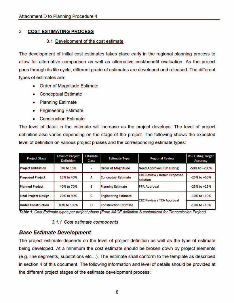
3 Cost Estimating Process ........................................................................................................ 8
3.1 Development of the cost estimate .................................................................................... 8
3.1.1 Cost estimate components ........................................................................................ 8
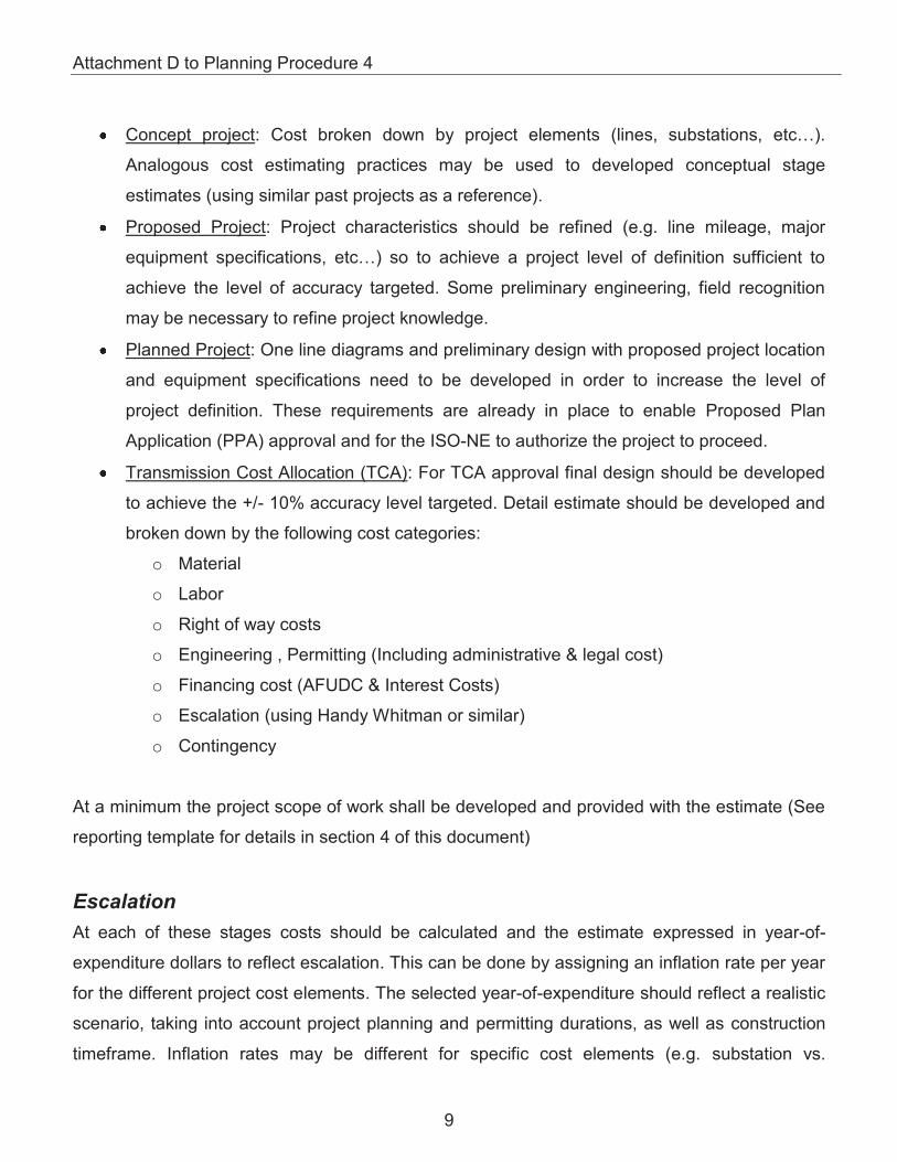
3.2 Cost Estimate Accuracy & Contingency......................................................................... 11
4 Project Cost Estimates Updates .......................................................................................... 11
4.1 Submission of Project Cost Estimate Updates. .............................................................. 11
4.2 Project Cost Estimate Template .................................................................................... 12
4.3 Project Cost Estimate Change Reporting Template ...................................................... 12
5 Document References ......................................................................................................... 16

Attachment D to Planning Procedure 4
3
1 PURPOSE
Project cost estimates are a key component of the regional system planning process and
provide a basis for key decisions to address both regional and local transmission system
upgrade needs. The purpose of this document is to provide consistent cost engineering terms
and definitions and a standardized approach to cost estimating in the region.
This document also outlines the active review and reporting of cost estimates throughout the
project life cycle from the planning and design to the construction phase. The proposed process
covered in this document will improve the ability for transmission owners in the region to provide
common estimates, increase project costs transparency and provide regular information about
the transmission investments made in the region and their impact to rates.
This document complements the current regional planning process and provides additional level
of detail to the project cost estimate review and validation. These guidelines have been
assemble with the collaboration of the New England Transmission Owner and will serve as
supporting document to the existing planning procedure.

Attachment D to Planning Procedure 4
4
2 TERMS AND DEFINITIONS
2.1 Cost engineering definitionsi
Cost Estimate: A prediction of quantities, cost, and/or price of resources required by the scope of an asset investment option, activity, or project. As a prediction, an estimate must address risks and uncertainties. Estimates are used primarily as inputs for budgeting, cost or value analysis, decision making in business, asset and project planning, or for project cost and schedule control processes. Cost estimates are determined using experience and calculating and forecasting the future cost of resources, methods, and management within a scheduled time frame.
Base Estimate: The Base Estimate is the original estimate (without contingency) in any
estimate class (A, B, C or D). The Base Estimate will not change while the project is in
the particular estimate class and all cost adjustments will be based on this estimate. For
a Base Estimate to change the project will need to be moved to a differed Estimate Class
Escalation: The provision in actual or estimated costs for an increase in the cost of
equipment, material, labor, etc., over that specified in the purchase order or contract due
to continuing price level changes over time. Inflation may be a component of escalation,
but non-monetary policy influences, such as supply-and-demand, are often components.
Contingency: An amount added to an estimate to allow for items, conditions, or events
for which the state, occurrence, or effect is uncertain and that experience shows will likely
result, in aggregate, in additional costs. Typically estimated using statistical analysis or
judgment based on past asset or project experience. Contingency usually excludes:
o Major scope changes such as changes in end product specification, capacities,
building sizes, and location of the asset or project;
o Extraordinary events such as major strikes and natural disasters;
o Escalation and currency effects.
Some of the items, conditions, or events for which the state, occurrence, and/or effect is
uncertain include, but are not limited to, planning and estimating errors and omissions,
minor price fluctuations (other than general escalation), design developments and
changes within the scope, and variations in market and environmental conditions.
Contingency is generally included in most estimates, and is expected to be expended.
Project: Based on commonly used Project Management terminology, Project’s definition
is as follow: “A temporary endeavor with a specific objective to be met within the

Attachment D to Planning Procedure 4
5
prescribed time and monetary limitations and which has been assigned for definition or
execution” (AACE / PMI). Regional Transmission projects are typically defined by the
transmission owner as a result of the solution study. Projects are broken down by
components in the RSP listing (Lines & Substations) but are typically permitted and
reviewed as a whole for efficiency and resource/costs savings.
Project Scope: The sum of all that is to be or has been invested in and delivered by the
performance of an activity or project. In project planning, the scope is usually documented
(i.e., the scope document).
Project Element: The breakdown of the Project into a subset. Examples of project
elements would be transmission lines, substation, switching stations, underground
transmission lines etc.
Change in Scope: A change in the defined deliverables or resources used to provide
them.
Right of way cost: All costs associated with the acquisition of new right of way including
easements, land purchases, and associated agent, surveying (relative to land acquisition)
and recording fees (as defined by FERC 350 account definition).
Level of Project Definition: This characteristic is based upon percent complete of
project definition (roughly corresponding to percent complete of engineering). The level of
project definition defines maturity or the extent and types of input information available to
the estimating process. Such inputs include project scope definition, requirements
documents, specifications, project plans, drawings, calculations, learning’s from past
projects, reconnaissance data, and other information that must be developed to define the
project.
2.2 Project planning stageii
The RSP (Regional System Planning) project list identifies regulated transmission solutions
proposed in response to the needs identified in a RSP or Needs assessment conducted
pursuant to Section 4.1 of Attachment K of the Open Access Transmission Tariff (OATT). The
RSP Project List identifies the proposed regulated transmission solutions separately as either a

Attachment D to Planning Procedure 4
6
Reliability Transmission Upgrade or a Market Efficiency Transmission Upgrade. Every project
evolves through various stages of development. These stages are as follow:
Concept: Projects that are being considered by its proponent as a potential solution to
meet a need identified by the ISO in a Needs Assessment or the RSP, but for which there
may be little or no analysis available to support the transmission project. A project charter
is developed at this stage.
Proposed: A regulated transmission solution that (i) has been proposed in response to a
specific need identified by the ISO in a Needs Assessment or the RSP and (ii) has been
evaluated or further defined and developed in a Solutions Study, as specified in Section
4.2(b) of Attachment K of the OATT, such that there is significant analysis that supports a
determination by the ISO, as communicated to the Planning Advisory Committee, that the
proposed regulated transmission solution would likely meet the need identified by the ISO
in a Needs Assessment or the RSP, but has not received support by the ISO under
Section I.3.9 of the Tariff.
Planned: A Transmission Upgrade that has been approved by the ISO under Section
I.3.9 of the Tariff.
Under Construction: A Transmission Upgrade that has received the approvals required
under the Tariff and engineering and/or construction is underway.
In-Service: A Transmission Upgrade that has been placed in commercial operation and
control jurisdiction turned over the local control center.
2.3 Examples of Contingency & Scope Change
The variance to the cost estimate baseline falls into the two categories defined in section 2.1,
contingency or scope changes. Contingency typically reflects the risks associated with some of
the project elements. These risks are identified, quantified and a cost is associated with these
risks. Scope changes on the other hand accounts for project costs incurred as a result of
changes to the project itself. The following list gives a few examples of each of these cost
categories.
Some examples for transmission project contingency are:

Attachment D to Planning Procedure 4
7
Field condition design adjustment (e.g. field conflict)
Incremental change to cost estimate (e.g. unit price increase) excluding general
escalation.
Estimating variances (e.g. quantity, equipment)
Design development and changes within the original scope (e.g. pole placement
less than 50ft)
Market & vendor variations (e.g. price delta between vendors)
Reasonable environmental condition or customer request adjustments (e.g.
avoiding stream)
Weather impact on construction (limited to minor delays of few days or less)
Permitting requirements (e.g. working hour restrictions, rare plants and species
protection measures)
Some examples for transmission project Scope changes are:
Substation site relocation
Design criteria change
Currency effects
Regulatory & permitting project definition changes (e.g. undergrounding
transmission or distribution lines, Army Corps of Engineer construction
requirements)
Project re-Routes or relocation from the original Scope
Changes to the project to accommodate compliance measures (Environmental,
Land impact mitigation)
Significant project delays (cost incurred through the escalation cost and the
carrying charges for the project, including capital interest)
Major schedule changes
Attachment D to Planning Procedure 4
9
Concept project: Cost broken down by project elements (lines, substations, etc…).
Analogous cost estimating practices may be used to developed conceptual stage
estimates (using similar past projects as a reference).
Proposed Project: Project characteristics should be refined (e.g. line mileage, major
equipment specifications, etc…) so to achieve a project level of definition sufficient to
achieve the level of accuracy targeted. Some preliminary engineering, field recognition
may be necessary to refine project knowledge.
Planned Project: One line diagrams and preliminary design with proposed project location
and equipment specifications need to be developed in order to increase the level of
project definition. These requirements are already in place to enable Proposed Plan
Application (PPA) approval and for the ISO-NE to authorize the project to proceed.
Transmission Cost Allocation (TCA): For TCA approval final design should be developed
to achieve the +/- 10% accuracy level targeted. Detail estimate should be developed and
broken down by the following cost categories:
o Material
o Labor
o Right of way costs
o Engineering , Permitting (Including administrative & legal cost)
o Financing cost (AFUDC & Interest Costs)
o Escalation (using Handy Whitman or similar)
o Contingency
At a minimum the project scope of work shall be developed and provided with the estimate (See
reporting template for details in section 4 of this document)
Escalation
At each of these stages costs should be calculated and the estimate expressed in year-of-
expenditure dollars to reflect escalation. This can be done by assigning an inflation rate per year
for the different project cost elements. The selected year-of-expenditure should reflect a realistic
scenario, taking into account project planning and permitting durations, as well as construction
timeframe. Inflation rates may be different for specific cost elements (e.g. substation vs.
Attachment D to Planning Procedure 4
11
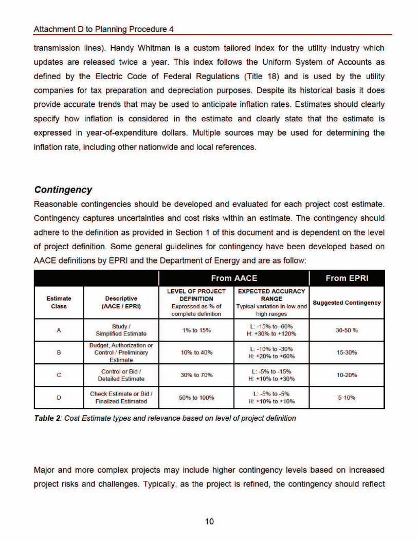
the shift of contingencies into actual cost categories. Transmission Owners should manage risks
and uncertainties to reduce the contingency used. However, per the AACE definition, historically,
contingency is expected to be expended and should be included in the estimates.
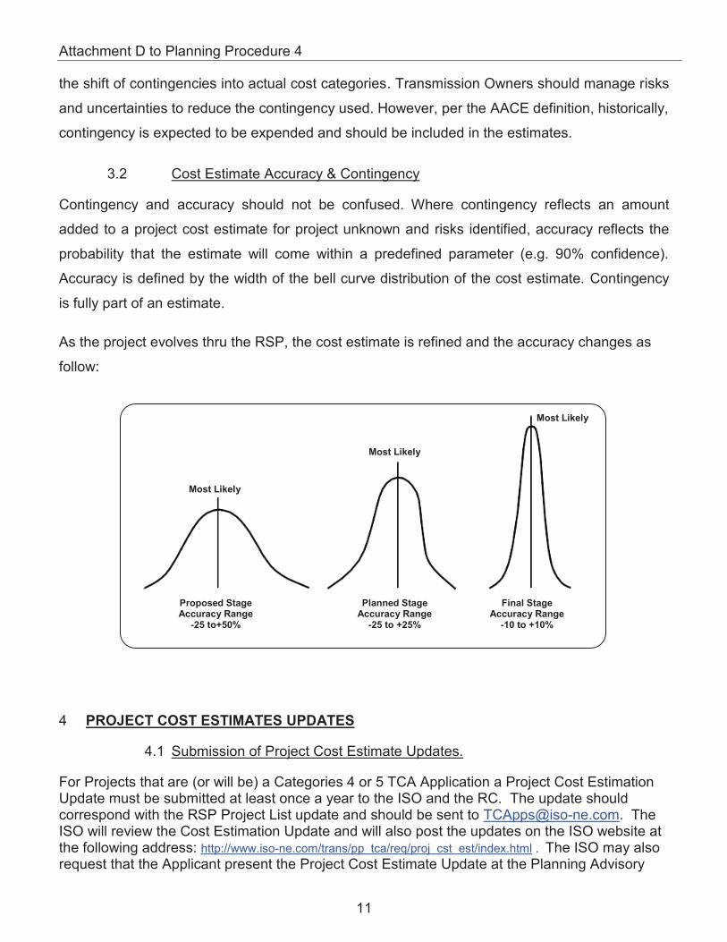
3.2 Cost Estimate Accuracy & Contingency
Contingency and accuracy should not be confused. Where contingency reflects an amount
added to a project cost estimate for project unknown and risks identified, accuracy reflects the
probability that the estimate will come within a predefined parameter (e.g. 90% confidence).
Accuracy is defined by the width of the bell curve distribution of the cost estimate. Contingency
is fully part of an estimate.
As the project evolves thru the RSP, the cost estimate is refined and the accuracy changes as
follow:
4 PROJECT COST ESTIMATES UPDATES
4.1 Submission of Project Cost Estimate Updates.
For Projects that are (or will be) a Categories 4 or 5 TCA Application a Project Cost Estimation Update must be submitted at least once a year to the ISO and the RC. The update should correspond with the RSP Project List update and should be sent to [email protected]. The ISO will review the Cost Estimation Update and will also post the updates on the ISO website at the following address: http://www.iso-ne.com/trans/pp tca/req/proj cst est/index.html . The ISO may also request that the Applicant present the Project Cost Estimate Update at the Planning Advisory
Proposed StageAccuracy Range
-25 to+50%
Planned StageAccuracy Range
-25 to +25%
Final StageAccuracy Range
-10 to +10%
Most Likely
Most Likely
Most Likely

Attachment D to Planning Procedure 4
12
Committee (PAC) up to three times a year. The applicant will be notified at least one meeting before they will be presenting to insure ample time to gather costs information.
4.2 Project Cost Estimate Template
The Project Cost Estimate Template will be used the first time a Project is reviewed. The Project Cost Template will be completed one time and not changed unless the Project estimates class changes. It is not necessary to submit a Project Cost Estimation Change Reporting Template when completing this template.
4.3 Project Cost Estimate Change Reporting Template
The Project Cost Estimate Change Reporting Template will be used to update project costs and completion percentage. This is the template that will be used once a Project Cost Estimation Template has been completed. It is not necessary to update the Project Cost Estimation Template when completing this Template.


Attachment D to Planning Procedure 4
14
Project Element 2 Project Element X Construction complete Energize/in-service


Appendix 3-2
Correspondence
MA Department of Marine
Fisheries and National Marine
Fisheries Service

Commonwealth of Massachusetts Division of Marine Fisheries
Annisquam River Marine Fisheries Station 30 Emerson Ave.
Gloucester, Massachusetts 01930(978)282-0308
fax (617)727-3337
March 19, 2013
Marc A. Bergeron Senior Project Manager Vanasse Hangen Brustlin, INC. 101 Walnut Street P.O. Box 9151 Watertown, MA 02472
Dear Mr. Bergeron,
Thank you for contacting The Division of Marine Fisheries (MarineFisheries) with an update on the proposed National Grid underground cable submarine and land route alternatives. As we noted in our letter of April 27, 2010, both proposed submarine cable routes would directly impact mapped eelgrass (Zostera
marina) meadows. Salem Harbor is an area of particular concern for MarineFisheries and other state and local organizations because of recent declines in eelgrass extent, coupled with decreases in water quality. Eelgrass extent in the harbor declined by 70% from 1995 to 2006 [1] . Eelgrass beds are important as nursery habitat for finfish and invertebrates and play a key role in nutrient cycling and sediment filtering. Avoiding further impacts is critical to eelgrass recovery efforts.
As stated in our 2010 letter, Salem Harbor provides essential forage habitat for a variety of fish and invertebrate species including alewife (Alosa pseudoharengus), blueback herring (Alosa aestivalis), rainbow smelt (Osmerus mordax), American eel (Anguilla rostrata), white perch (Morone americana), Atlantic tomcod (Microgadus tomcod), Atlantic cod (Gadus morhua) and American lobster (Homarus americanus). It is also habitat for the forage, spawning, and early development of winter flounder (Pseudopleuronectes
americanus) an important recreational and commercial species currently in decline according to state and federal assessments. Soft shell clams (Mya arenaria) and blue mussel (Mytilus edulis) have been mapped by MarineFisheries within the project footprint.
Through correspondence in early March with Vivian Kimball of your office, I understand that the submarine route alternatives for installation of the cable again include horizontal directional drilling (HDD) and Jetplowing. From a fisheries habitat perspective, HDD will have impacts at the points of entry and exit and at the mid water station, but impacts to the seafloor would be avoided though most of the length of the submarine cable route. Alternatively, Jet plowing will result in disturbance within a larger area beneath Salem Harbor. Jet plowing will increase suspended sediments, causing turbidity and, if not effectively contained, further water quality degradation. Finally, the Jet plow alternative will have the greatest potential to impact eelgrass. Furthermore, as stated in our 2010 letter, the harbor supports shellfish and finfish habitat that may also be impacted. To avoid negative effects to marine fisheries resources, we recommend that National Grid further develop the land based route alternatives, and identify the alternative that will have the least environmental impact.
If you have any questions regarding these comments, please call me at our Gloucester Office (978-282-0308 x. 168)
Paul J. Diodati
Director
Deval Patrick
Governor
Ian A. Bowles
Secretary
Mary B. Griffin
Commissioner

2
Sincerely,
Tay Evans Environmental Review Coordinator
cc. Vivian Kimball (VHB) Ken Chin (DEP) Kathryn Glenn (CZM) Mike Johnson (NMFS)
References
1. Costello, C.T. and W.J. Kenworthy. 2010. Twelve year mapping and change analysis of eelgrass (Zostera marina) distribution in Massachusetts (USA) identifies state wide decline. Estuaries and Coasts.

Commonwealth of Massachusetts Division of Marine Fisheries
Annisquam River Marine Fisheries Station 30 Emerson Ave.
Gloucester, Massachusetts 01930(978)282-0308
fax (617)727-3337
April 27, 2010
Marc A. Bergeron Senior Project Manager Vanasse Hangen Brustlin, INC. 101 Walnut Street P.O. Box 9151 Watertown, MA 02472
Dear Mr. Bergeron,
The Division of Marine Fisheries, (MarineFisheries), has reviewed the project options proposed by National Grid for the replacements of two 115 kilovolt underground cables located between the Salem Harbor substation and the Canal Street substation in Salem, Massachusetts. Below we provide comments on the marine fisheries resources and habitats at the project site.
Salem Harbor provides essential forage habitat for a variety of fish and invertebrate species including alewife (Alosa
pseudoharengus), blueback herring (Alosa aestivalis), rainbow smelt (Osmerus mordax), American eel (Anguilla
rostrata), white perch (Morone americana), Atlantic tomcod (Microgadus tomcod), Atlantic cod (Gadus morhua) and American lobster (Homarus americanus). It is also habitat for the forage, spawning, and early development of winter flounder (Pseudopleuronectes americanus) an important recreational and commercial species currently in decline according to state and federal assessments.
Soft shell clams (Mya arenaria) and blue mussel (Mytilus edulis) have been mapped by MarineFisheries within the project footprint. Pockets of eelgrass (Zostera marina) have also been mapped by DEP in Salem Harbor, falling within the project footprint. Eelgrass beds are important as nursery habitat for finfish and invertebrates and play a key role in nutrient cycling and sediment filtering.
National Grid is proposing two possible underground options for cable replacement; a land route and a route below Salem Harbor. If the Salem Harbor route is selected as the preferred alternative, a detailed argument for why the land route is not practicable will likely be requested by resource agencies in order to ensure that the project is avoiding and minimizing impacts to marine fisheries resources and habitats.
If you have any questions regarding these comments, please call me at our Gloucester Office (978-282-0308 x. 168)
Sincerely,
Tay Evans Environmental Review Coordinator
TE/ko
Paul J. Diodati
Director
Deval Patrick
Governor
Ian A. Bowles
Secretary
Mary B. Griffin
Commissioner


Appendix 3-3
Feasibility Study of
Constructing the New S-145
and T-146 Transmission Lines
via a Horizontal Directional
Drill Installation under the
Salem Harbor

Feasibility Study of Constructing the New S-145 and T-146 Transmission Lines via a Horizontal Directional
Drill Installation under the Salem Harbor
prepared for
New England Power Company d/b/a National GridWaltham, MA
July 2013
Project No. 53411
prepared by
Burns & McDonnell Engineering Company, Inc.Kansas City, Missouri
COPYRIGHT © 2013 BURNS & McDONNELL ENGINEERING COMPANY, INC.

EXECUTIVE SUMMARY
Burns & McDonnell (BMcD) was requested to conduct an investigation into the feasibility and costs for
installing the new S-145 and T-146 circuits under Salem Harbor via a Horizontal Directional Drill (HDD)
for the purposes of avoiding a land installation through parts of Salem, MA. In support of this request,
BMcD, along with their subconsultant Haley & Aldrich, Inc. (H&A), has prepared this Feasibility Study
of Constructing the New S-145 and T-146 Transmission Lines via a Horizontal Directional Drill
Installation Under the Salem Harbor. Please note the following clarifications:
This Feasibility Study is limited to the installation of electrical cables under Salem Harbor via HDD
and does not reflect on other electrical cable or HDD projects. All other projects should be evaluated
independently on their own merits.
This Feasibility Study does not compare the installation of the cables via HDD to other potential
installation alternatives including underground or overhead cables.
This Feasibility Study does not identify, or include the cost of obtaining, the environmental,
construction and zoning permits required for the installation of electrical cables under Salem Harbor
via HDD, nor does it make a determination of the feasibility of acquiring said permits.
In conducting this study, representatives of New England Power Company d/b/a National Grid (NEP),
BMcD, and H&A visited the project site to evaluate proposed horizontal directional drill work zones.
Based on the electrical and physical installation requirements of the project, the appropriate cable
technology for the installation was selected. Available information from internal and external sources
was then compiled and reviewed relative to subsurface conditions, including areas of contaminated
ground. Additionally, reports prepared for the City of Salem and the US Army Corps of Engineers
relative to planned and existing use of Salem Harbor were obtained and reviewed. Finally, utilizing this
accumulated information, the following issues associated with this installation were evaluated:
Work area for drilling and pipe installation
HDD alignments across Salem Harbor, including potential platform locations.
Existing geological conditions
Existing biological conditions in the harbor
Contamination of existing soil and water in the planned work locations
Future land uses such as a proposed deep water cruise terminal
Existing utilities and structure foundations along the proposed alignment(s)
Street or land-based construction from the HDD end points to the substations

Cost and schedule risks associated with the installation of the harbor crossing via HDD construction
Estimates of probable construction costs for this project alternative.
As this evaluation was performed with regard to technical feasibility only, it does not address permitting
or property rights acquisition associated with the HDD installation.
The results of this investigation are summarized below.
Installation Summary
NEP seeks to install two 115 kV circuits (the S-145 and the T-146) connecting the Company’s Salem
Harbor Substation and its Canal Street Substation. High-Pressure Fluid-Filled (HPFF) cable is
recommended for use for this HDD project alternative. An HPFF cable system consists of three cables,
one of each phase, installed in a single cable pipe. To meet the required ratings, each circuit will consist
of three cables per phase; therefore, six total cable pipes will be necessary for the two circuits for the
length of the project. For the HDD portion, each cable pipe would be installed via a single bore from a
given launch point to a given receive point, with a minimum separation between each as necessary to
achieve the ratings at various points along the HDD alignment.
Each circuit would enter Salem Harbor near the Salem Harbor Power Plant, and exit Salem Harbor at the
Palmer Cove baseball field. Due to the subsurface space constraints, the two circuits would be split
between two launch locations for the northeastern HDD end points near the Salem Harbor Power Plant.
These locations are shown on the figure below as Entry/Exit Point #1 and Entry/Exit Point #2.
Due both to the need for cable pull points, and to the lack of work space at the end points of the HDDs for
assembling pipe for long pulls across the harbor, temporary, pile-supported mid-harbor platforms would
be needed. Utilizing these platforms, the pipe could be assembled adjacent to land and floated into
position for pullback at reasonable lengths. The following figure shows the anticipated alignment,
platform locations, and segment identifications:
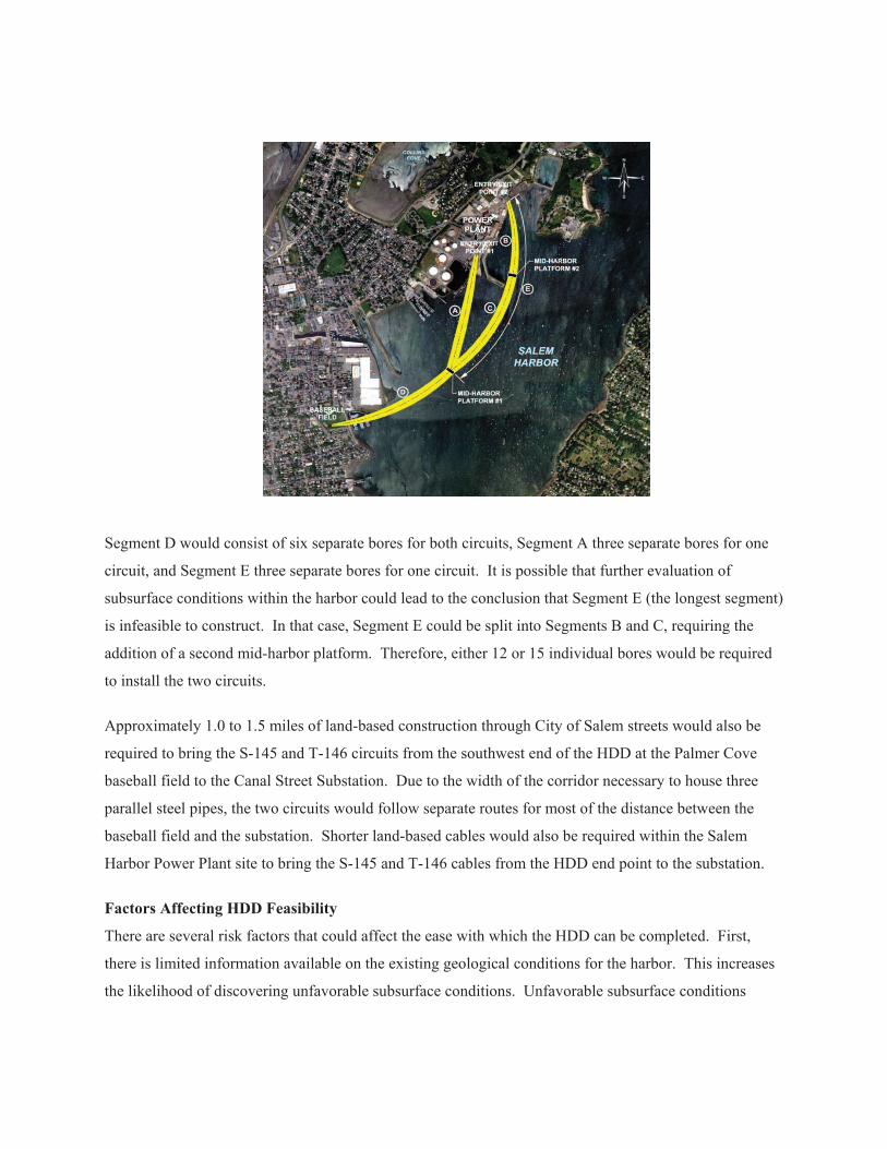
Segment D would consist of six separate bores for both circuits, Segment A three separate bores for one
circuit, and Segment E three separate bores for one circuit. It is possible that further evaluation of
subsurface conditions within the harbor could lead to the conclusion that Segment E (the longest segment)
is infeasible to construct. In that case, Segment E could be split into Segments B and C, requiring the
addition of a second mid-harbor platform. Therefore, either 12 or 15 individual bores would be required
to install the two circuits.
Approximately 1.0 to 1.5 miles of land-based construction through City of Salem streets would also be
required to bring the S-145 and T-146 circuits from the southwest end of the HDD at the Palmer Cove
baseball field to the Canal Street Substation. Due to the width of the corridor necessary to house three
parallel steel pipes, the two circuits would follow separate routes for most of the distance between the
baseball field and the substation. Shorter land-based cables would also be required within the Salem
Harbor Power Plant site to bring the S-145 and T-146 cables from the HDD end point to the substation.
Factors Affecting HDD Feasibility
There are several risk factors that could affect the ease with which the HDD can be completed. First,
there is limited information available on the existing geological conditions for the harbor. This increases
the likelihood of discovering unfavorable subsurface conditions. Unfavorable subsurface conditions

could lead to potential drill stem or pipe failure or collapse of the bore hole. Either of these results could
increase the duration or the cost (or both) of the HDD.
In addition, available data suggests that contaminated soils may be present at both the Salem Harbor
Power Plant site and the Palmer Cove baseball field, which is located on the site of a capped landfill.
Cross-contamination could occur during the HDD if a bore hole were to transmit contaminated ground
water to previously uncontaminated areas or underground aquifers. An environmental mitigation plan
would decrease, but not eliminate, the likelihood of such cross-contamination.
The HDD process may also result in inadvertent return of drill mud to the surface (frac-out) at unplanned
locations (i.e. a location in between launch and receive points). As pressured mud is used to maintain
borehole integrity and to remove soil cuttings, success of the drilling operation could be jeopardized.
Because of the long pull length required for this project, HPFF cable is recommended for this installation.
However, there is currently only one manufacturer of HPFF cable in the United States. As of the issuance
of this report, that manufacturer is quoting lead times of twenty-four to thirty months for new cable
orders. Thus, it may be impossible for NEP to obtain the required materials and construct the project
before the proposed Footprint Plant expects to come online.
Cost
The anticipated cost of the HDD installation, including both HDD and land-based installation of the steel
cable pipes plus cable and dielectric fluid installation, is estimated to be $109,640,000 at a tolerance level
of +50/-25%. This cost estimate does not include the costs related to improvements needed at the Canal
Street and Salem Harbor substations, permitting costs for the cables or substation improvements, or
AFUDC and similar costs.
Schedule
The total duration of the HDD installation alternative is expected to be approximately fourteen to sixteen
months. This includes seven to nine months actual drilling and pipe installation time from a platform (or
platforms) in Salem Harbor, concurrent land-based installation, plus the remaining time to pull and splice
cables, make final pipe welds around the splices, overboard the platform-constructed splices into the
harbor, and disassemble and remove the platforms.
Long Term Maintenance Issues
A permanent installation of this type presents several long-term maintenance issues. First, should a cable
failure occur along the under-harbor portion, it would be difficult to identify and locate the problem area.
Once the problem area is located, a similar level of effort as the initial construction would be needed in
order to remedy the issue. This effort would include the construction of a mid-harbor platform,
excavation of the direct-buried splice, pulling of the new cable, and reinstalling the repaired splice back
into the harbor. Any leakage of the dielectric fluid from a damaged cable pipe would be released into
Salem Harbor.
Additionally, permanent restrictions would be required within the harbor near the location(s) of the mid-
harbor platform(s), due to the shallow burial of the cable pipes in those locations. The total trench lengths
at the mid-harbor platform(s) are anticipated to be approximately 300 feet long. The permanently
restricted areas would be approximately 200 feet wide by 500 feet long at each platform location so to
encompass a portion of the HDD-installed pipe as it dives to a deep enough depth below the sea floor to
be considered safe from outside impacts. Examples of the type of activities that could be prohibited
within this zone would include dredging, exploratory borings, installation of new moorings, use of spud
barges, and anchoring of larger ships.
Finally, because HPFF cables would be necessary, there would be regular inspection and maintenance
needs for the dielectric fluid pumping plant, as well as the added maintenance procedure to rotate the
spare cable reel(s) every three months in order to keep the cable impregnated with the dielectric fluid.
Summary
Overall, the project appears to be technically feasible, but with risks, costs, and other considerations as
identified and discussed in detail within this document. It should be noted that this analysis is specific to
this project only and the various factors associated with it. For other projects that may be proposed for
different purposes and/or with different location-specific constraints and considerations, a potential HDD
installation would be evaluated based on the unique and particular aspects of those projects, and may
yield different results.

TABLE OF CONTENTS
Page No.
1.0 INTRODUCTION............................................................................................... 1-1
2.0 ELECTRICAL REQUIREMENTS...................................................................... 2-1
2.1 Cable Technology ................................................................................................ 2-1
2.2 Ampacity Requirements ....................................................................................... 2-2
2.3 Determination of Size and Number of Cables Required ..................................... 2-3
3.0 HDD INSTALLATION ....................................................................................... 3-1
3.1 Existing Harbor Conditions ................................................................................. 3-1
3.2 Factors Affecting HDD Feasibility .................................................................... 3-10
3.3 Evaluation of HDD Alignments ......................................................................... 3-15
3.4 HDD Pipe Stresses ............................................................................................. 3-24
3.5 HDD Feasibility Factors .................................................................................... 3-28
3.6 Project Risk Register .......................................................................................... 3-37
3.7 Conclusions and Recommendations .................................................................. 3-45
4.0 CABLE PULLING ............................................................................................. 4-1
5.0 LAND ROUTES................................................................................................. 5-1
5.1 Canal Street Substation ........................................................................................ 5-1
5.2 Salem Harbor Substation ..................................................................................... 5-2
6.0 COMPLICATIONS AND LONG TERM MAINTENANCE ISSUES.................... 6-1
7.0 CONSTRUCTION COST ESTIMATE OVERVIEW ........................................... 7-1
7.1 Summary of Construction and Easement Acquisition Costs ............................... 7-1
8.0 ANTICIPATED CONSTRUCTION SCHEDULE................................................ 8-1
APPENDIX A CABLE PULLING CALCULATIONS
APPENDIX B LAND ROUTE COST ESTIMATES
APPENDIX C HDD DURATION OF INSTALLATION AND ESTIMATED COSTS
APPENDIX D EASEMENT ACQUISITION ESTIMATED COSTS
APPENDIX E PIPE STRESS CALCULATIONS
APPENDIX F SOURCES OF INFORMATION
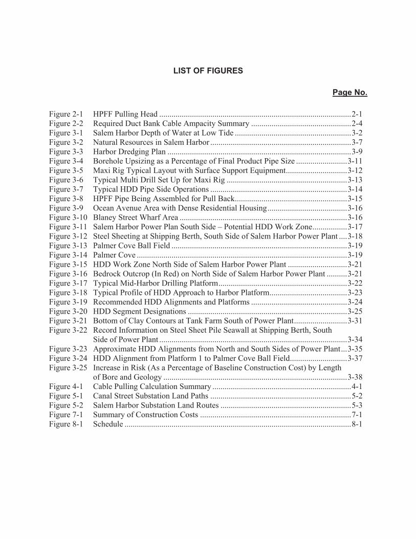
LIST OF FIGURES
Page No.
Figure 2-1 HPFF Pulling Head .............................................................................................. 2-1
Figure 2-2 Required Duct Bank Cable Ampacity Summary ................................................. 2-4
Figure 3-1 Salem Harbor Depth of Water at Low Tide ......................................................... 3-2
Figure 3-2 Natural Resources in Salem Harbor ..................................................................... 3-7
Figure 3-3 Harbor Dredging Plan .......................................................................................... 3-9
Figure 3-4 Borehole Upsizing as a Percentage of Final Product Pipe Size ......................... 3-11
Figure 3-5 Maxi Rig Typical Layout with Surface Support Equipment .............................. 3-12
Figure 3-6 Typical Multi Drill Set Up for Maxi Rig ........................................................... 3-13
Figure 3-7 Typical HDD Pipe Side Operations ................................................................... 3-14
Figure 3-8 HPFF Pipe Being Assembled for Pull Back ....................................................... 3-15
Figure 3-9 Ocean Avenue Area with Dense Residential Housing ....................................... 3-16
Figure 3-10 Blaney Street Wharf Area .................................................................................. 3-16
Figure 3-11 Salem Harbor Power Plan South Side – Potential HDD Work Zone ................. 3-17
Figure 3-12 Steel Sheeting at Shipping Berth, South Side of Salem Harbor Power Plant .... 3-18
Figure 3-13 Palmer Cove Ball Field ...................................................................................... 3-19
Figure 3-14 Palmer Cove ....................................................................................................... 3-19
Figure 3-15 HDD Work Zone North Side of Salem Harbor Power Plant ............................. 3-21
Figure 3-16 Bedrock Outcrop (In Red) on North Side of Salem Harbor Power Plant .......... 3-21
Figure 3-17 Typical Mid-Harbor Drilling Platform ............................................................... 3-22
Figure 3-18 Typical Profile of HDD Approach to Harbor Platform ...................................... 3-23
Figure 3-19 Recommended HDD Alignments and Platforms ............................................... 3-24
Figure 3-20 HDD Segment Designations .............................................................................. 3-25
Figure 3-21 Bottom of Clay Contours at Tank Farm South of Power Plant .......................... 3-31
Figure 3-22 Record Information on Steel Sheet Pile Seawall at Shipping Berth, South Side of Power Plant ............................................................................................ 3-34
Figure 3-23 Approximate HDD Alignments from North and South Sides of Power Plant ... 3-35
Figure 3-24 HDD Alignment from Platform 1 to Palmer Cove Ball Field ............................ 3-37
Figure 3-25 Increase in Risk (As a Percentage of Baseline Construction Cost) by Length of Bore and Geology .......................................................................................... 3-38
Figure 4-1 Cable Pulling Calculation Summary .................................................................... 4-1
Figure 5-1 Canal Street Substation Land Paths ..................................................................... 5-2
Figure 5-2 Salem Harbor Substation Land Routes ................................................................ 5-3
Figure 7-1 Summary of Construction Costs .......................................................................... 7-1
Figure 8-1 Schedule ............................................................................................................... 8-1
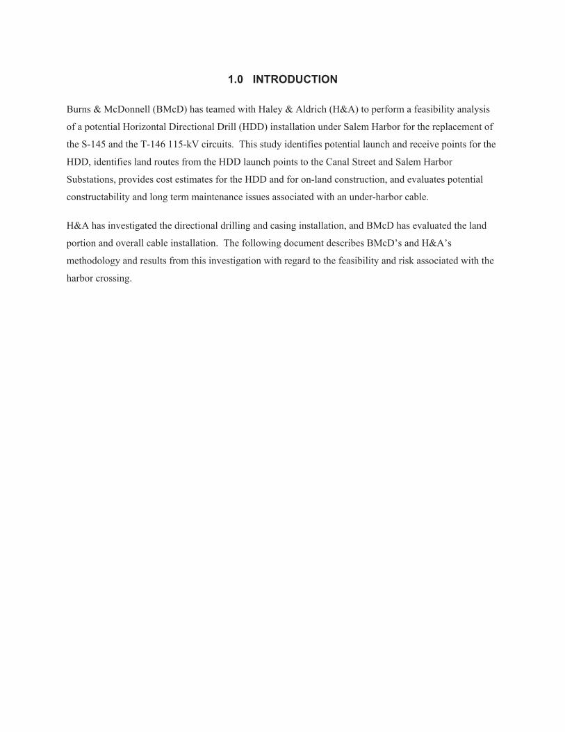
1.0 INTRODUCTION
Burns & McDonnell (BMcD) has teamed with Haley & Aldrich (H&A) to perform a feasibility analysis
of a potential Horizontal Directional Drill (HDD) installation under Salem Harbor for the replacement of
the S-145 and the T-146 115-kV circuits. This study identifies potential launch and receive points for the
HDD, identifies land routes from the HDD launch points to the Canal Street and Salem Harbor
Substations, provides cost estimates for the HDD and for on-land construction, and evaluates potential
constructability and long term maintenance issues associated with an under-harbor cable.
H&A has investigated the directional drilling and casing installation, and BMcD has evaluated the land
portion and overall cable installation. The following document describes BMcD’s and H&A’s
methodology and results from this investigation with regard to the feasibility and risk associated with the
harbor crossing.

2.0 ELECTRICAL REQUIREMENTS
2.1 CABLE TECHNOLOGY
There are two basic types of cable technology suited for use in underground transmission projects: HPFF
cables; and solid-dielectric cables with cross-linked polyethylene (XLPE) insulation. For an HDD
installation across Salem Harbor, the most appropriate cable technology is HPFF cables. There are three
primary reasons that this technology is superior to other cable technologies for this project: allowable pull
length, borehole diameter, and sheath bonding requirements.
2.1.1 Allowable Pull Length
Typically, HPFF cables allow for cable pulls approximately 25 to 50 percent longer than pulls for a
comparable XLPE cable. At the time of installation, HPFF cables are individually smaller and lighter
than a comparable XLPE cable, because the dielectric fluid that serves as the primary cable insulation is
installed after the cables are pulled. The lighter weight of the HPFF cable allows for longer cable length
on a reel. Additionally, as all three phase cables are pulled into a single cable pipe as a bundle, the
tension during the pull is distributed between the three cables via use of a pulling head attached to all
three conductors as shown in Figure 2-1.
Figure 2-1 HPFF Pulling Head
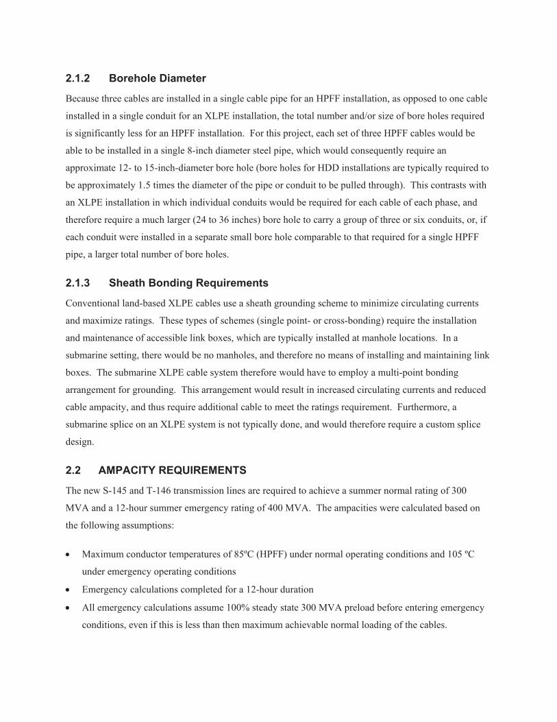
2.1.2 Borehole Diameter
Because three cables are installed in a single cable pipe for an HPFF installation, as opposed to one cable
installed in a single conduit for an XLPE installation, the total number and/or size of bore holes required
is significantly less for an HPFF installation. For this project, each set of three HPFF cables would be
able to be installed in a single 8-inch diameter steel pipe, which would consequently require an
approximate 12- to 15-inch-diameter bore hole (bore holes for HDD installations are typically required to
be approximately 1.5 times the diameter of the pipe or conduit to be pulled through). This contrasts with
an XLPE installation in which individual conduits would be required for each cable of each phase, and
therefore require a much larger (24 to 36 inches) bore hole to carry a group of three or six conduits, or, if
each conduit were installed in a separate small bore hole comparable to that required for a single HPFF
pipe, a larger total number of bore holes.
2.1.3 Sheath Bonding Requirements
Conventional land-based XLPE cables use a sheath grounding scheme to minimize circulating currents
and maximize ratings. These types of schemes (single point- or cross-bonding) require the installation
and maintenance of accessible link boxes, which are typically installed at manhole locations. In a
submarine setting, there would be no manholes, and therefore no means of installing and maintaining link
boxes. The submarine XLPE cable system therefore would have to employ a multi-point bonding
arrangement for grounding. This arrangement would result in increased circulating currents and reduced
cable ampacity, and thus require additional cable to meet the ratings requirement. Furthermore, a
submarine splice on an XLPE system is not typically done, and would therefore require a custom splice
design.
2.2 AMPACITY REQUIREMENTS
The new S-145 and T-146 transmission lines are required to achieve a summer normal rating of 300
MVA and a 12-hour summer emergency rating of 400 MVA. The ampacities were calculated based on
the following assumptions:
Maximum conductor temperatures of 85ºC (HPFF) under normal operating conditions and 105 ºC
under emergency operating conditions
Emergency calculations completed for a 12-hour duration
All emergency calculations assume 100% steady state 300 MVA preload before entering emergency
conditions, even if this is less than then maximum achievable normal loading of the cables.

Actual maximum calculated normal ampacity, based on a conductor temperature equal to 85 C, may
exceed required normal rating; however, cables operated in this condition will not meet the required
emergency rating.
Load Factor is assumed to be 0.90 for all configurations
2.3 DETERMINATION OF SIZE AND NUMBER OF CABLES REQUIRED
Based on the potential HDD alignments and landfall locations discussed in Section 3.0 of this report,
three controlling locations were analyzed as part of this study to determine the size and number of cables
required: at the Salem Power Plant, at the midpoint of the alignment under Salem Harbor, and at the ball
field west of Palmer Cove. The following assumptions were made regarding the thermal resistivity of the
soils (“thermal rho”) and the ambient earth temperatures at these locations, based on previous work in the
Northeast United States:
Thermal rho: 150 ºC cm/W at the ball field; 250 ºC cm/W at the midpoint of the alignment under
Salem Harbor; and 220 ºC cm/W at the sea wall.
Summer ambient earth temperature: 20 ºC at the ball field; 15 ºC at the midpoint of the alignment
under Salem Harbor; and 18 ºC at the sea wall.
The three controlling locations are discussed in further detail as follows:
2.3.1 Power Plant Installation Location
At the entrance/exit point south of the Salem Harbor Power Plant, the HDD would need to descend to a
depth of approximately 70 feet to pass under a seawall without damaging the existing sheeting and piles.
Most of the soil in this area is fill that was used to build up this area of the power plant site. The fill
would likely consist of large pieces of broken concrete and large aggregate fill with large void areas in
which heat could be trapped. This trapped heat would raise the temperature of the cables and cause a de-
rating of the cable. This de-rating impact contributes to the number of cables per phase needed to reach
the required ratings.
2.3.2 Harbor Mid-Point Installation Location
The second location that was analyzed was at the mid-point of the harbor, well away from the mid-harbor
drilling platform. At this location, the bores would be approximately 60 to 70 feet below the bottom of
the harbor. The harbor floor contains a thick stratum of organic matter that can trap the heat below the
surface. This trapped heat would raise the temperature of the cables and cause a de-rating of the cable.
This organic layer along with the needed depth contributes to the number of cables required per circuit.

2.3.3 Baseball Field Installation Location
The final location analyzed was the point where the bores surface within the ball fields west of Palmer
Cove. In this area, the bores are at their shallowest position as they ascend to the surface. The soil in this
area has the potential to be best for the bores as it relates to thermal properties. The combination of better
thermal properties of the soil and shallow depth leads to a drastic decrease in the required separation of
the bores. If the further investigation reveals that this area was once a landfill that contains highly organic
soil and large voids, the minimum separation will need to be increased.
2.3.4 Summary Table
Based on the three locations identified above, Figure 2-2 shows the cable size and minimum separation
between cables pipes necessary to achieve the ampacity rating required for the project.
Figure 2-2 Required Duct Bank Cable Ampacity Summary
Location Number Required
Ratings
(MVA)
Minimum Separation
(edge-to-edge)
Location 1 (3500 kcmil HPFF Cable, three cables per phase), Salem Harbor Power Plant
300 Normal,
400 Emergency
30’
Location 2 (3500 kcmil HPFF Cable, three cables per phase), Salem Harbor Mid-Point
300 Normal,
400 Emergency
35’
Location 3 (3500 kcmil HPFF Cable, three cables per phase), Ball Field
300 Normal,
400 Emergency
5’