Embed Size (px)
Citation preview

Attachment D
Ring Shear Testing Report (Dr. Timothy Stark)


PORT OF ANCHORAGE INTERMODAL EXPANSION: Bootlegger Cove Clay Analysis and Testing
Anchorage, Alaska
(Figure by CH2M-HILL)
Prepared for:
CH2M HILL, Inc. 1100 112th Avenue, Suite 400
Bellevue, WA 98004
Prepared by: Dr. Timothy D. Stark, P.E., D.GE, F.ASCE
Stark Consultants, Inc. P.O. Box 0133
Urbana, IL 61803-0133 (217) 840-4951
November 5, 2012

1
TABLE OF CONTENTS
Page
PURPOSE AND SCOPE OF STUDY ...................................................................................................... 2
SOIL DESCRIPTION ........................................................................................................................... 2
PRIOR BOOTLEGGER COVE CLAY TESTING ...................................................................................... 5
INDEX PROPERTY TESTING ............................................................................................................ 12
DRAINED TORSIONAL RING SHEAR TESTING ................................................................................. 13
UNDRAINED TORSIONAL RING SHEAR TESTING ............................................................................ 17
(a) Constant Volume Ring Shear Apparatus .................................................................... 17
(b) Constant Volume Ring Shear Test Procedure ............................................................ 18
(c) Constant Volume Ring Shear Test Results ................................................................. 19
(d) Rapid Constant Volume Ring Shear Test Results ....................................................... 22
(e) Healed Constant Volume Ring Shear Test Results ..................................................... 23
SUMMARY ..................................................................................................................................... 26
LIMITATIONS ................................................................................................................................. 27
REFERENCES CITED ....................................................................................................................... 27
APPENDIX A – STARK AND CONTRERAS (1998) ............................................................................. 30

Bootlegger Cove clay Analysis and Testing Dr. Timothy D. Stark
Port of Anchorage Intermodal Expansion 11/5/2012
Purpose and Scope of Study At the request of CH2M HILL, Inc., this report presents the results and analysis of index property and torsional ring shear tests conducted on the Bootlegger Cove clay soil from the Port of Anchorage (POA) Intermodal Expansion Project in Anchorage, Alaska. In particular, the project site is the North Expansion of the POA located north of downtown Anchorage, Alaska. The center for the project site is at a longitude of approximately -149.883 degrees and at a latitude of approximately 61.249 degrees. At present, the POA expansion project makes use of the patented Open Cell Sheet Pile OCSP® system for the wharf and the berthing area. The OCSP® system was developed and patented by PND Engineers, Inc. (PND) of Anchorage, Alaska, in 2004 (Patent No. US 6,715,964 B2) and has been used since about 2000 to construct wharf and berthing structures for other projects. Torsional ring shear testing was requested by CH2M HILL, Inc. to investigate shear response of Bootlegger Cove clay at large shear displacements. It is anticipated that the results were used by CH2M HILL, Inc. in stability and permanent deformation evaluations of the OCSP system. The table of contents above presents the structure of this report which presents the data and analysis for the Bootlegger Cove clay investigated during this study.
Soil Description The index property and torsional ring shear testing was performed on Bootlegger Cove clay taken from Boring Number BH-002-12 Sample Tube ST-5. Sample Tube ST-5 was obtained from a depth of 99.0 to 101.0 feet and is located in the Fourth (IV) Facies of the Bootlegger Cove Formation (BCF). Figure 1 is an aerial view of the POA provided by CH2M HILL and identifies the location of Boring Number BH-002-12. The cone penetration sounding (CPT-26) adjacent to soil boring BH-002-12 is shown in Figure 2. CPT-26 was conducted prior to construction of the OCSP structure. Soil boring BH-002-12 was drilled specifically to collect the nominal 5-inch diameter samples used for the ring shear testing described in this report. Figure 2 shows the depth of the fill/foundation interface at this location is 48 to 50 feet. The ground surface elevation, i.e. top of fill, is approximately 35 feet (MLLW). CPT-26 shows the two Bootlegger Cove clay facies and the depth of ST-5 at 99 to 101 feet. The elevation range of ST-5 from roughly EL -64 to EL -66 ft MLLW is shown by the red rectangle in Figure 2. Sample Tube ST-5 was obtained from Bootlegger Cove clay Facies IV (F.IV) as defined by Updike and Carpenter (1986). Updike and Carpenter (1986) use the following definitions for the various facies of the Bootlegger Cove clay that are shown in Figure 2:
F.IV (upper layer): “Silty clay and clayey silt with silt and fine sand lenses”.
F.I (lower layer): “Clay with very minor amounts of silt and sand”.

Bootlegger Cove clay Analysis and Testing Dr. Timothy D. Stark
Port of Anchorage Intermodal Expansion 11/5/2012
3
Figure 3 presents two photographs of the grey Bootlegger Cove clay prior to trimming of a constant volume ring shear specimen. Figure 3(a) shows a one inch thick sample that was cut from the end of the 5-inch diameter sample tube ST-5. The ring of the metal sample tube was also cut with a band saw. The metal ring surrounding the one inch thick sample was cut vertically to facilitate removal as shown in Figure 3(b). Figure 3(b) also shows the consistency and uniformity of the grey Bootlegger Cove clay. One of the Bootlegger Cove clay samples contained two light grey silt stringers, otherwise the one inch thick samples cut from the end of the 5-inch diameter sample tube ST-5 did not contain silt stringers and were similar to the material shown in Figure 3(b).
Figure 1. Aerial view of Port of Anchorage Intermodal Expansion Project and red circle
indicates location of Boring Number BH-002-12 (figure prepared by CH2M HILL)

Bootlegger Cove clay Analysis and Testing Dr. Timothy D. Stark
Port of Anchorage Intermodal Expansion 11/5/2012
4
Figure 2. Cone penetration sounding CPT-26 adjacent to Boring Number BH-002-12
(figure prepared by CH2M HILL)
Bootlegger Cove clay Analysis and Testing Dr. Timothy D. Stark
Port of Anchorage Intermodal Expansion 11/5/2012
5
(a) (b)
Figure 3. View of one inch thick sample cut from ST-5 sample tube and close-up of grey Bootlegger Cove clay before trimming a constant volume ring shear specimen
Prior Bootlegger Cove Clay Testing A number of landslides involving cohesive soils have occurred during earthquakes. The most notable examples are the Fourth Avenue, L-Street, Government Hill, and Turnagain Heights landslides in Anchorage that occurred during the 1964 Alaska earthquake (Seed 1968 and Idriss 1985). Figure 4 is a photograph of the Fourth Avenue landslide in which the Denali Theater dropped about one story so the theater awning is at the same level as Fourth Avenue. A comprehensive study of the Fourth Avenue landslide was conducted by Woodward-Clyde Consultants (1982) as part of an evaluation of the Fourth Avenue area for development of a major state office complex. This study concluded that the slide was not caused by liquefaction of sand seams but by a large undrained strength loss in the slightly overconsolidated clay of the Bootlegger Cove formation (Woodward-Clyde 1982; Idriss 1985; Updike et al. 1988). However, a laboratory or field apparatus that could measure the undrained post-peak strength loss of the cohesive soil was not available during these studies to confirm this hypothesis. Stark and Contreras (1996) developed a laboratory constant volume torsional ring shear apparatus that allows measurement of the magnitude and rate of undrained post-peak strength loss and the undrained residual shear strength in cohesive soils. Stark and Contreras (1998), see Appendix A, used this apparatus and the resulting data to re-evaluate the Fourth Avenue landslide and develop recommendations for evaluating the seismic stability of slopes in cohesive soils.

Bootlegger Cove clay Analysis and Testing Dr. Timothy D. Stark
Port of Anchorage Intermodal Expansion 11/5/2012
6
Figure 4. View of Denali Theater awning with Fourth Avenue on the right after the 1964
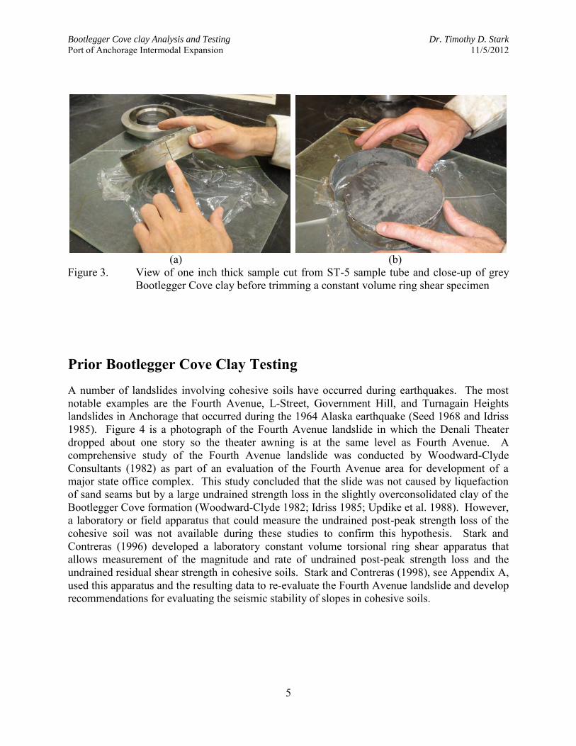
earthquake (photograph by the U.S. Geological Survey) Stark and Contreras (1998) present a re-evaluation of the Fourth Avenue landslide in Anchorage that occurred during the 1964 Alaska earthquake. Laboratory constant volume ring shear tests were conducted on 5-inch diameter samples obtained using a 6 inch inside diameter hollow stem auger. These samples were obtained in a parking lot north of the businesses that front Fourth Avenue (see Figure 5). The results of these tests were compared to back-calculated shear strengths of the Bootlegger Cove clay to determine the mobilized strength of the clay. The comparison shows that slide blocks that moved less than 0.15 m mobilized at least 80 percent of the undrained peak shear strength. Slide blocks that moved between 0.15 to 2.5 m mobilized an undrained shear strength between the peak and residual shear strengths. Slide blocks that displaced more than 2.5 m mobilized the undrained residual strength. Figure 6 presents the decrease in undrained shear strength with block displacement described above.
Bootlegger Cove clay Analysis and Testing Dr. Timothy D. Stark
Port of Anchorage Intermodal Expansion 11/5/2012
7
(a) (b)
Figure 5. (a) Drill rig and (b) five inch diameter sample tubes in parking lot north of Fourth Avenue in Anchorage, Alaska and overlying the Fourth Avenue slide mass
Stark and Contreras (1998) also tested other cohesive soils to investigate the development of an undrained post-peak strength loss. Table 1 presents a summary of the natural soils tested by Stark and Contreras (1998) using the constant volume ring shear apparatus. It can be seen that these four natural soils exhibit a limited range of plasticity and clay size fraction, and thus similar peak and residual undrained strength ratios. In addition, the shear displacement required to mobilize the peak and residual strength conditions are in agreement. Subsequently, Stark (2001) performed constant volume ring shear tests on the Bootlegger Cove clay obtained during the investigation and design for the development of the Port MacKenzie project. The main results of the Port MacKenzie testing are also shown in Table 1. Based on prior and current testing, data on the undrained shear behavior and post-peak strength loss is available for the Bootlegger Cove clay at three locations near Anchorage, Alaska. Figure 7 is a map that shows the location and proximity of these three Bootlegger Cove clay locations. Table 2 presents a list of the drained and undrained torsional ring shear tests performed during this study including the testing details such as, consolidation stress, drainage condition, shear displacement rate, and test termination. Table 1 also includes a summary of the constant volume ring shear tests on the Bootlegger Cove clay obtained from the Port of Anchorage. The Port of Anchorage values are shown in red and are in agreement with the values obtained from the Fourth Avenue landslide and Port MacKenzie investigations described herein.

Bootlegger Cove clay Analysis and Testing Dr. Timothy D. Stark
Port of Anchorage Intermodal Expansion 11/5/2012
8
Figure 6. Variation of undrained shear strength ratio with ground surface displacement (figure from Stark and Contreras, 1998)

Bootlegger Cove clay Analysis and Testing Dr. Timothy D. Stark
Port of Anchorage Intermodal Expansion 11/5/2012
9
Figure 7. Map showing earthquake induced landsides during 1964 earthquake and three
sites at which constant volume ring shear testing has been performed to investigate the undrained shear behavior of Bootlegger Cove clay (map prepared by CH2M HILL)

Bootlegger Cove clay Analysis and Testing Dr. Timothy D. Stark
Port of Anchorage Intermodal Expansion 11/5/2012
10
Table 1: Undrained ring shear test results on undisturbed Bootlegger Cove clay from three sites near Anchorage, Alaska and other cohesive soils
Soil deposit
and location
Liquid limit (%)
Plastic limit (%)
Clay size
fraction (%<0.002 m)
Ring Shear vertical
consolidation stress ’vc
(kPa)
Preconsolidation pressure
’ (kPa)
Undrained peak shear
strength ratio su/’vc
Shear displacement
at peak strength ratio
(mm)
Undrained residual strength
ratio sur/’vc
Shear displacement
at residual strength ratio
(mm)
Undrained residual strength
ratio/ Undrained peak shear
strength ratio
Bootlegger Cove clay, inside Fourth Ave. landslide, Anchorage, Alaska
40 34 36 38 39
20 19 21 21 20
59 57 56 55 62
100 230 300 400 500
280-320
0.28 0.28 0.24 0.23 0.23
1.2 1.1 1.3 1.8 1.8
0.07 0.07 0.06 0.06 0.06
55 75 75
120 130
0..25 0.25 0.25 0.26 0.26
Bootlegger Cove clay, outside Fourth Ave. landslide, Anchorage, Alaska
42 40 42 41
23 21 23 22
47 42 49 45
150 225 400 500
405
0.31 0.32 0.31 0.30
1.5 1.6 1.7 1.7
0.11 0.10 0.11 0.11
95 110 125 140
0.35 0.31 0.35 0.37
Bootlegger Cove clay, Port MacKenzie, Anchorage, Alaska
29 35 35
17 20 21
38 47 53
180.0 359.1 718.2
300 383 575
0.21 0.31 0.29
0.70 2.0 2.0
0.04 0.06 0.05
168 219 170
0.19 0.19 0.17
Bootlegger Cove clay, Port of Anchorage, Anchorage, Alaska
31 37
16 19
51 53
100 200 300 400 600
440
0.19 0.32 0.33 0.37 0.32
0.40 0.98 1.1 1.7 2.4
0.03 0.16 0.15 0.14 0.09
33 31 69 78
102
0.16 0.50 0.45 0.38 0.28
Drammen clay, Danvik-gate, Drammen, Norway
47 48 47
23 24 25
70 72 65
95 255 400
140 0.27 0.22 0.20
1.1 1.3 1.1
0.09 0.11 0.11
19 16 60
0.33 0.50 0.55
Cohesive alluvium, Enid Dam, Enid, Mississippi
30 28 23 25 30
22 22 19 22 22
19 20 17 20 20
95.8 147 191 287 383
122.4 138.9 81.4
143.5 134.5
0.19 0.27 0.24 0.23 0.23
2.2 1.1 1.1 1.2 1.2
0.10 0.05 0.07 0.07 0.06
52 77 70 72 75
0.52 0.19 0.29 0.30 0.26
Cohesive alluvium, Jackson, Alabama 59 31 51
51.8 79.4 100
75.8 0.21 0.23 0.23
0.50 0.35 0.37
0.13 0.16 0.14
36 50 38
0.62 0.69 0.61
Upper Bonneville clay, Salt Lake City, Utah
46 23 33
47.9 95.8
191.5 383
47.9 95.8
191.5 383
0.32 0.36 0.31 0.34
0.30 0.60 1.2 2.0
0.11 0.15 0.12 0.14
39 25 29 36
0.34 0.42 0.39 0.41

Bootlegger Cove clay Analysis and Testing Dr. Timothy D. Stark
Port of Anchorage Intermodal Expansion 11/5/2012
11
Table 2: Constant volume ring shear (CVRS) and drained ring shear (DRS) tests performed on undisturbed and remolded Bootlegger Cove clay from ST-5 sample tube for Port of Anchorage Intermodal Expansion Project (table prepared by CH2M-HILL)
Boot- Test
Sample legger Ring Overconsol-
Test Boring Tube Depth Cove Shear idation In Situ Reconsol. Shearing Shearing Test
ID ID ID Range Clay Test Ratio 'vp 'vm 'vc 'vc Status
No. No. No. (ft) Facies Type (OCR) (psi) (psi) (psi) (kPa)
CVRS-01 BH-002-12 ST-5 99 to 101 F.IV Constant Vol./Undrained 4.41 64.0 14.5 14.5 (100 kPa) Done
CVRS-02 BH-002-12 ST-5 99 to 101 F.IV Constant Vol./Undrained 2.21 64.0 29.0 29.0 (200 kPa) Done
CVRS-03 BH-002-12 ST-5 99 to 101 F.IV Constant Vol./Undrained 1.47 64.0 43.5 43.5 (300 kPa) Done
CVRS-04 BH-002-12 ST-5 99 to 101 F.IV Constant Vol./Undrained 1.10 64.0 58.0 58.0 (400 kPa) Done
CVRS-06 BH-002-12 ST-5 99 to 101 F.IV Constant Vol./Undrained 1.00 64.0 87.0 87.0 (600 kPa) Done
DRS-08 BH-002-12 ST-5 99 to 101 F.IV Drained/Constant Vert. Stress 4.41 64.0 14.5 14.5 (100 kPa) Done
DRS-09 BH-002-12 ST-5 99 to 101 F.IV Drained/Constant Vert. Stress 1.10 64.0 58.0 58.0 (400 kPa) Done
DRS-10 BH-002-12 ST-5 99 to 101 F.IV Drained/Constant Vert. Stress 1.00 64.0 87.0 87.0 (600 kPa) Done
CVRS-13 BH-002-12 ST-5 99 to 101 F.IV FASTER (0.18 mm/min) Constant Vol./Undrained 1.10 64.0 58.0 58.0 (400 kPa) Done
CVRS-14 BH-002-12 ST-5 99 to 101 F.IV HEALING Constant Vol./Undrained 1.10 64.0 58.0 58.0 (400 kPa) Done
CVRS-15 BH-002-12 ST-5 99 to 101 F.IV HEALING Constant Vol./Undrained-Remolded Specimen 1.10 64.0 58.0 58.0 (400 kPa) Done
DRS-16 BH-002-12 ST-5 99 to 101 F.IV MULTI-STAGE Drained/Constant Vert. Stress ASTM D6467 7.00 64.0 87.0 87.0 (50 to 700 kPa) Done
Ring Shear Applied Vertical Stresses

Bootlegger Cove clay Analysis and Testing Dr. Timothy D. Stark
Port of Anchorage Intermodal Expansion 11/5/2012
12
Index Property Testing Two sets of index property tests were conducted on Bootlegger Cove clay obtained from different portions of ST-5. The index property tests (Atterberg limits, particle size analysis, and hydrometer) were conducted in accordance with ASTM standards (D4318, D136, and D422, respectively). The results are shown in Tables 3 and 4 and show the Bootlegger Cove clay is fairly uniform. Based on the index property results in Tables 3 and 4, the Bootlegger Cove clay classifies as a low plasticity clay (CL) according to the Unified Soil Classification System. Table 3: Index Property and Consolidation Data for Sample Tube ST-5 (Depth 99 to 101 feet)
and Drained Ring Shear Sample #1 (Sample was obtained from bottom 2 to 3 inches of sample tube ST-5)
In-situ Natural Water Content ~19% Liquid Limit 31% Plastic Limit 16% Plastic Index 15% Clay Size Fraction (<0.002 mm) 51% Preconsolidation Pressure from CH2M HILL 9,216 psf Largest Particle Size ~6 mm Percent Passing #4 ~100% Percent Passing #200 86% Description Based On USCS CL – low plastic inorganic clay, silty clay Table 4: Index Property and Consolidation Data for Sample Tube ST-5 (Depth 99 to 101 feet)
and Drained Ring Shear Sample #2 (Sample was obtained from bottom 3 to 4 inches of sample tube ST-5)
In-situ Natural Water Content ~20% Liquid Limit 37% Plastic Limit 19% Plastic Index 18% Clay Size Fraction (<0.002 mm) 53% Preconsolidation Pressure from CH2M HILL 9,216 psf Largest Particle Size ~6 mm Percent Passing #4 ~100% Percent Passing #200 83% Description Based On USCS CL – low plastic inorganic clay, silty clay

Bootlegger Cove clay Analysis and Testing Dr. Timothy D. Stark
Port of Anchorage Intermodal Expansion 11/5/2012
13
Drained Torsional Ring Shear Testing A modified Bromhead ring shear apparatus (Stark and Eid, 1993) and most of the procedure presented in ASTM D6467 were used to measure the drained residual shear strength of these three undisturbed samples. However, an undisturbed specimen was used for these three drained ring shear tests instead of a remolded specimen as allowed in ASTM D6467. The undisturbed ring shear specimens were trimmed from the Port of Anchorage sample tube ST-5 in a moist room using a specimen container fabricated to allow undisturbed annular specimens to be trimmed directly into the container. The new specimen container is described by Stark and Contreras (1996) and consists of eight parts that can be joined and disassembled for the trimming and shear phases of the test. For the trimming phase the inner cutter ring, inner ring, outer cutter ring, upper outer ring, and holder are assembled to create the trimming apparatus. After trimming, the specimen container is converted to the configuration used for shearing in the ring shear apparatus. For the shearing phase the inner and outer cutter rings and holder are removed. The porous disc, center core, and lower outer ring are added to create the shearing specimen container. Assemblage of the trimming apparatus and specimen container are illustrated in Stark and Contreras (1996). After trimming of the annular specimen, the specimen is placed in the ring shear device and consolidated to the desired effective normal stress by increasing the normal load in small increments, i.e., load increment ratio of unity. Each load increment is maintained until the end of primary consolidation is achieved. Once the end of primary consolidation under the desired normal stress is achieved, the specimen is ready for drained shearing at a drained displacement rate of 0.018 mm/min. This shear displacement rate is the slowest rate possible in the Bromhead ring shear device and it has been successfully used to test soils that are much more plastic, i.e., lower permeability, than the Bootlegger Cove clay in sample tube ST-5. Drained torsional ring shear tests were conducted on undisturbed specimens of the Bootlegger Cove clay from sample tube ST-5 at effective normal stresses of 2,088, 8,355, and 12,531 psf (100, 400, and 600 kPa). These tests were performed to measure the drained residual strength of the Bootlegger Cove clay for comparison with the undrained residual strengths described below. These tests are identified as DRS-08, DRS-09, and DRS-10. The drained shear stress-displacement relationships at effective normal stresses of 2,088 psf (100 kPa), 8,352 psf (400 kPa), and 12,531 psf (600 kPa) are presented in Figure 8 and were used to obtain the drained peak and residual shear stresses for each specimen. Table 5 presents the values of drained peak and residual shear stress, and the corresponding drained residual friction angle, that were obtained from these measured shear stress-displacement relationships. These values of residual shear stress and the corresponding effective normal stresses were used to develop the drained peak and residual failure envelopes shown in Figure 9. The measured peak and residual strength envelopes are slightly stress-dependent but could be reasonably modeled using a linear strength envelope. However, the measured drained peak and

Bootlegger Cove clay Analysis and Testing Dr. Timothy D. Stark
Port of Anchorage Intermodal Expansion 11/5/2012
14
residual shear stresses measured for each specimen (see Table 5) can be used directly in a slope stability analysis to model the stress-dependent nature of the strength envelopes instead of a friction angle.
Figure 8. Drained shear stress-displacement relationships from ring shear tests on
undisturbed Bootlegger Cove clay from sample tube ST-5

Bootlegger Cove clay Analysis and Testing Dr. Timothy D. Stark
Port of Anchorage Intermodal Expansion 11/5/2012
15
Table 5. Summary of Drained Ring Shear Test Results for Sample Tube ST-5 (Note: NA =
Not Available)
Test No. in
Table 2
Drained Peak and Residual Shear Stress at each Effective Normal Stress
(psf)
Drained Residual Friction Angle
(degrees) 1,044
psf 2,088
psf 4,177
psf 8,354
psf 12,530
psf 14,620
psf ST-5 Testing
Stark et al. (2005)
Correlation
DRS-08 898.2/ 798.0
20.9º 26.6º
DRS-09
4674.9/ 4249.2
27.0º 29.6º
DRS-10
6171.5/ 5717.9
24.5º 21.5º
DRS-16 NA/ 357.0
NA/ 502.9
NA/ 1039.5
NA/ 2177.8
NA/ NA
NA/ 4369.0
18.9-16.6º 23.8º
Figure 9. Drained peak and residual strength envelopes for undisturbed Bootlegger Cove
clay from sample tube ST-5

Bootlegger Cove clay Analysis and Testing Dr. Timothy D. Stark
Port of Anchorage Intermodal Expansion 11/5/2012
16
To verify the drained residual strengths shown in Table 5 and the drained residual strength envelope in Figure 9, the drained residual strength of the soil used in the DRS-08, DRS-09, and DRS-10 tests was used to conduct a multi-stage residual strength ring shear test in accordance with ASTM D6467. In this test a remolded specimen is initially consolidated to 14,620 psf (700 kPa), unloaded to 2,088 psf (100 kPa), and then pre-sheared by rotating the ring shear base for at least one complete revolution using a shear displacement rate of 6.68 mm/min. After pre-shearing, the specimen is allowed to equilibrate before drained shearing. The specimen is then sheared at a drained displacement rate of 0.018 mm/min at the first effective normal stress of 2,088 psf (100 kPa). This is the slowest shear displacement rate possible in the Bromhead ring shear device and it has been successfully used to test soils that are more plastic, i.e., have lower permeability, than the Bootlegger Cove clay. After a drained residual strength condition is established at 2,088 psf (100 kPa), shearing is stopped and the normal stress increased to 200 kPa (4,177 psf). After consolidation at 200 kPa (4,177 psf), the specimen is sheared again until a drained residual condition is obtained. This procedure is then repeated for effective normal stresses of 8,352 psf (400 kPa) and 14,620 psf (700 kPa). The remolded specimens were obtained by air-drying a representative soil sample, passing the soil through U.S. Standard Sieve No. 40, and then mixing the sample with distilled water until a water content near the liquid limit was obtained. The sample was then allowed to hydrate for at least 24 hours in a constant moisture room. A spatula was used to place the remolded soil paste into the annular specimen container. The ring shear specimen is annular with an inside diameter of 70 mm and an outside diameter of 100 mm and is 5 mm thick to facilitate consolidation. Annular bronze porous discs secured to the bottom of the specimen container and the top loading platen provides drainage during consolidation and shearing. Both porous discs have a machined or knurled surface to facilitate interlock of the soil specimen with the porous discs to prevent slippage at the specimen bottom and force shearing to occur in the soil at or just below the bottom of the knurled surface of the top porous disc. The drained shear stress-displacement relationships at effective normal stresses of 1,044 psf (50 kPa), 2,088 psf (100 kPa), 4,177 psf (200 kPa), 8,352 psf (400 kPa), and 14,620 psf (700 kPa) are presented in Figure 10 and were used to obtain the drained residual shear stresses for each effective normal stress. These values of residual shear stress and the corresponding effective normal stresses are plotted in Figure 9. Table 5 also shows the secant residual friction angles estimated from the empirical relationship proposed by Stark and Eid (1994) and updated by Stark et al. (2005). The empirical correlation uses the liquid limit, clay size fraction (% <0.002 mm), and effective normal stress to estimate the stress-dependent residual failure envelope. The liquid limit estimates the clay mineralogy, the clay size fraction quantifies the amount of the clay mineral, and the effective normal stress captures the stress dependent nature of the residual strength. These secant residual friction angles were estimated using a liquid limit of 34 and a clay-size fraction greater than 50%.

Bootlegger Cove clay Analysis and Testing Dr. Timothy D. Stark
Port of Anchorage Intermodal Expansion 11/5/2012
17
Figure 10. Drained shear stress-displacement relationships from multi-stage ring shear test
on remolded Bootlegger Cove clay from sample tube ST-5 using ASTM D6467
Undrained Torsional Ring Shear Testing
(a) Constant Volume Ring Shear Apparatus Taylor (1952) introduced the use of a constant volume shear test to measure the undrained peak shear strength. A modified direct shear apparatus was used by Taylor (1952) to perform constant volume tests on Boston Blue Clay. Bjerrum and Landva (1966) introduced the use of the direct simple shear apparatus to measure the undrained peak shear strength of Manglerud clay, which also maintains a constant volume. However, undrained triaxial, direct shear, and direct simple shear apparatuses cannot measure the undrained residual strength because only a limited amount of continuous shear displacement can be imposed along a failure surface in these devices. As a result, it was necessary for Stark and Contreras (1996) to develop a torsional ring shear apparatus to evaluate the undrained post-peak strength loss and residual strength of cohesive soils.
To measure the undrained peak and residual shear strengths, the original Bromhead (1979) ring
shear apparatus was modified to conduct undrained (constant volume) tests (Stark and Contreras
1996). The modifications include a mechanism for adjusting the normal stress during shear, such
that the volume change during shear is negligible and thus the specimen is undrained during

Bootlegger Cove clay Analysis and Testing Dr. Timothy D. Stark
Port of Anchorage Intermodal Expansion 11/5/2012
18
shear. The reduction in normal stress is assumed to be equal to the shear induced pore-water
pressures (Stark and Contreras 1996). A new specimen container was also fabricated to allow
undisturbed specimens to be trimmed directly into the container. The ring shear specimen is
annular with an inside diameter of 70 mm and an outside diameter of 100 mm. The specimen is confined radially by the specimen container, which is 10 mm deep. Annular porous discs are
secured to the bottom of the specimen container and to the loading platen. The porous discs are
serrated to prevent slippage at the porous stone/soil interfaces during shear.
The undisturbed ring shear specimens were trimmed from the Port of Anchorage sample tube
ST-5 in a moist room. Remolded specimens were used for the index property testing, a multi-
stage drained torsional ring shear test (DRS-16), and one of the constant volume ring shear tests
(CVRS-15). Ring shear tests on remolded specimens were conducted to establish the normally
consolidated peak and residual failure envelopes for comparison with the results of the
undisturbed specimen tests and to assess the sensitivity of the Bootlegger Cove clay in ST-5. A
remolded specimen was obtained by mixing undisturbed material with distilled water until the
water content is at or near the liquid limit. Afterwards the sample was allowed to rehydrate for
two days in a moist room. A spatula was used to place the remolded soil paste into the annular
specimen container. The undrained (constant volume) ring shear tests were conducted at a shear
displacement rate of 0.018 mm/min (Stark and Eid 1994). In tests where the specimen was normally-consolidated, the normal stress was reduced during shear to maintain a constant volume/undrained condition. For tests where the specimen was over-consolidated, the normal stress was either reduced or increased during shear, depending on whether compression or dilation of the specimen was occurring, respectively, to maintain a constant volume/undrained condition. The reduction or increase in normal stress is assumed to be equal to the shear induced pore-water pressures.
(b) Constant Volume Ring Shear Test Procedure The constant volume mechanism consists of a steel rod that is connected to the end of the horizontal beam that applies the normal stress to the top of the specimen. Attached to the steel rod is a load cell, which is shown in Figure 12 and has a wire leading to a digital readout device. A nut is threaded to the top of the steel rod and is adjusted during shear to reduce the amount of normal load transferred to the loading platen. The nut connected to the steel rod is used in combination with the vertical digital dial gauge to adjust the normal stress, such that the specimen thickness remains constant during shear. Adjustments are made by manually rotating the nut an amount required to maintain zero vertical displacement of the soil specimen. When the nut is rotated, a portion of the dead weight being applied to the horizontal beam is transmitted to the rod and the load cell indicates the magnitude of this load via the digital readout device. Additional details of the constant volume ring shear apparatus are presented by Stark and Contreras (1996).

Bootlegger Cove clay Analysis and Testing Dr. Timothy D. Stark
Port of Anchorage Intermodal Expansion 11/5/2012
19
Figure 12. Photograph of constant volume ring shear system attached to modified Bromhead
ring shear device
In the constant volume ring shear apparatus, the specimen is sheared by rotating the specimen or specimen container past the stationary upper loading platen at a drained constant rate less than or equal to 0.018 mm/minute. The procedure described by Gibson and Henkel (1954) was used to determine the shear displacement rate of 0.018 mm/minute so zero pore-water pressures were generated throughout the specimen. A drained shear displacement rate is used so that little, if any, excess pore-water pressure is induced during shear. The Bootlegger Cove clay from sample tube ST-5 was primarily contractive during shear because the applied effective normal stress resulted in an overconsolidation ratio (OCR) between one and four (see Table 2). Because the specimens were primarily contractive during shear, the normal stress was reduced during shear to maintain a constant specimen height or volume. It is assumed that the decrease in applied vertical stress during shear is equivalent to the increase in shear-induced pore-water pressure that would occur in an undrained test with constant vertical stress. The validity of this pore-water pressure assumption for constant volume tests was verified by Dyvik et al. (1987) for the direct simple shear apparatus and by Berre (1981) for the triaxial compression apparatus.
(c) Constant Volume Ring Shear Test Results Figure 13 shows the undrained shear stress-shear displacement relationships from constant volume ring shear tests on undisturbed specimens of Bootlegger Cove clay (CVRS-01, 02, 03,
Bootlegger Cove clay Analysis and Testing Dr. Timothy D. Stark
Port of Anchorage Intermodal Expansion 11/5/2012
20
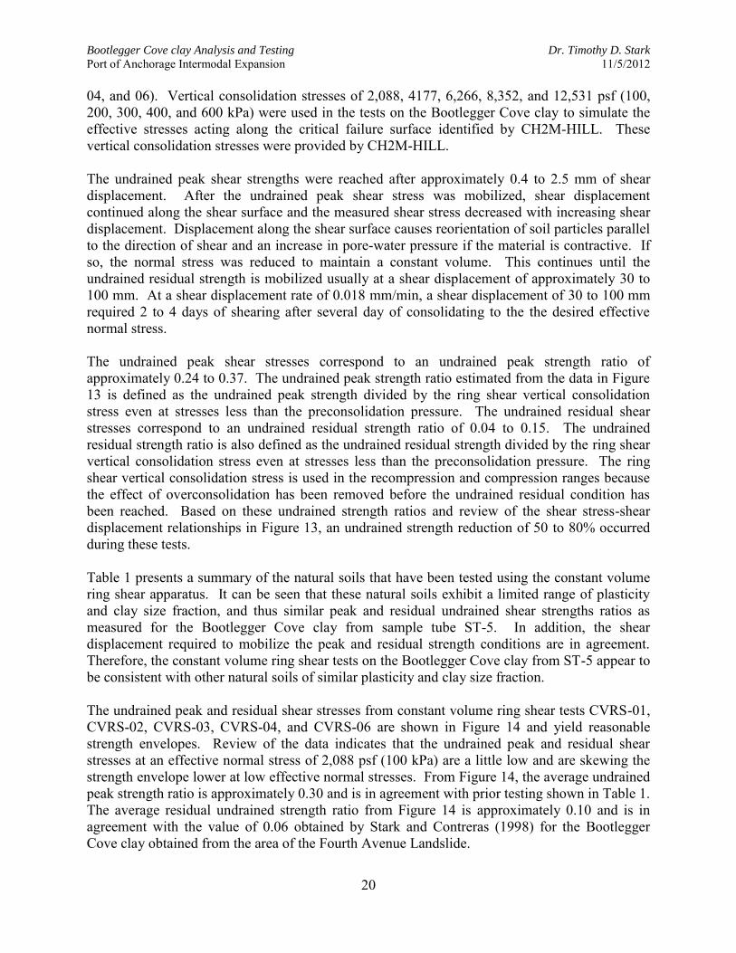
04, and 06). Vertical consolidation stresses of 2,088, 4177, 6,266, 8,352, and 12,531 psf (100, 200, 300, 400, and 600 kPa) were used in the tests on the Bootlegger Cove clay to simulate the effective stresses acting along the critical failure surface identified by CH2M-HILL. These vertical consolidation stresses were provided by CH2M-HILL. The undrained peak shear strengths were reached after approximately 0.4 to 2.5 mm of shear displacement. After the undrained peak shear stress was mobilized, shear displacement continued along the shear surface and the measured shear stress decreased with increasing shear displacement. Displacement along the shear surface causes reorientation of soil particles parallel to the direction of shear and an increase in pore-water pressure if the material is contractive. If so, the normal stress was reduced to maintain a constant volume. This continues until the undrained residual strength is mobilized usually at a shear displacement of approximately 30 to 100 mm. At a shear displacement rate of 0.018 mm/min, a shear displacement of 30 to 100 mm required 2 to 4 days of shearing after several day of consolidating to the the desired effective normal stress.
The undrained peak shear stresses correspond to an undrained peak strength ratio of approximately 0.24 to 0.37. The undrained peak strength ratio estimated from the data in Figure 13 is defined as the undrained peak strength divided by the ring shear vertical consolidation stress even at stresses less than the preconsolidation pressure. The undrained residual shear stresses correspond to an undrained residual strength ratio of 0.04 to 0.15. The undrained residual strength ratio is also defined as the undrained residual strength divided by the ring shear vertical consolidation stress even at stresses less than the preconsolidation pressure. The ring shear vertical consolidation stress is used in the recompression and compression ranges because the effect of overconsolidation has been removed before the undrained residual condition has been reached. Based on these undrained strength ratios and review of the shear stress-shear displacement relationships in Figure 13, an undrained strength reduction of 50 to 80% occurred during these tests. Table 1 presents a summary of the natural soils that have been tested using the constant volume ring shear apparatus. It can be seen that these natural soils exhibit a limited range of plasticity and clay size fraction, and thus similar peak and residual undrained shear strengths ratios as measured for the Bootlegger Cove clay from sample tube ST-5. In addition, the shear displacement required to mobilize the peak and residual strength conditions are in agreement. Therefore, the constant volume ring shear tests on the Bootlegger Cove clay from ST-5 appear to be consistent with other natural soils of similar plasticity and clay size fraction. The undrained peak and residual shear stresses from constant volume ring shear tests CVRS-01, CVRS-02, CVRS-03, CVRS-04, and CVRS-06 are shown in Figure 14 and yield reasonable strength envelopes. Review of the data indicates that the undrained peak and residual shear stresses at an effective normal stress of 2,088 psf (100 kPa) are a little low and are skewing the strength envelope lower at low effective normal stresses. From Figure 14, the average undrained peak strength ratio is approximately 0.30 and is in agreement with prior testing shown in Table 1. The average residual undrained strength ratio from Figure 14 is approximately 0.10 and is in agreement with the value of 0.06 obtained by Stark and Contreras (1998) for the Bootlegger Cove clay obtained from the area of the Fourth Avenue Landslide.

Bootlegger Cove clay Analysis and Testing Dr. Timothy D. Stark
Port of Anchorage Intermodal Expansion 11/5/2012
21
Figure 13. Undrained shear stress-displacement relationships from constant volume ring
shear tests on undisturbed Bootlegger Cove clay from sample tube ST-5
Figure 14. Undrained peak and residual strength envelopes for undisturbed and remolded
Bootlegger Cove clay specimens from sample tube ST-5

Bootlegger Cove clay Analysis and Testing Dr. Timothy D. Stark
Port of Anchorage Intermodal Expansion 11/5/2012
22
(d) Rapid Constant Volume Ring Shear Test Results Another series of constant volume ring shear tests were conducted to investigate the effect, if any, of a faster shear displacement rate on the response of undisturbed Bootlegger Cove clay from sample tube ST-5. A constant volume ring shear test was conducted at a shear displacement rate ten (10) times faster than the initial test at an effective normal stress of 8,352 psf (400 kPa). In other words, constant volume ring shear test CVRS-13 was conducted at a shear displacement rate of 0.18 mm/min for comparison with CVRS-04 which was conducted a 0.018 mm/min. A faster shear displacement rate was used to investigate whether or not additional strength loss, i.e., particle reorientation and/or pore-water pressure generation, would occur at a faster shear displacement rate. This test was performed to ensure that a different undrained strength would not occur in the field than observed in the laboratory. Both tests (CVRS-04 and CVRS-13) were conducted on undisturbed specimens and at an effective normal stress of 8,352 psf (400 kPa). Figure 15 shows the undrained shear stress-shear displacement relationships from these constant volume ring shear tests at different shear displacement rates at a vertical consolidation stress of 8,352 psf (400 kPa). Figure 15 shows there is little difference in the undrained peak strengths (149 kPa versus 142 kPa) for these two tests. As a result, it was concluded that a shear displacement rate of 0.018 mm/min was appropriate and yielded a representative undrained response in the constant volume ring shear tests. The faster constant volume ring shear test (CVRS-13) was not continued to a residual strength condition because there is little particle reorientation, and thus pore-water pressure generation, at the residual condition so the constant volume ring shear test with a shear displacement rate of 0.18 mm/minute was stopped shortly after the peak shear stress was measured. There is little difference between the undrained peak strengths for the two different shear displacement rates so it was concluded that the peak strengths were not affected by shear displacement rate.

Bootlegger Cove clay Analysis and Testing Dr. Timothy D. Stark
Port of Anchorage Intermodal Expansion 11/5/2012
23
Figure 15. Undrained shear stress-displacement relationships from constant volume ring
shear tests at different shear displacement rates on undisturbed Bootlegger Cove clay from sample tube ST-5
(e) Healed Constant Volume Ring Shear Test Results Another series of constant volume ring shear tests were conducted to investigate the possibility of a preexisting shear surface in the Bootlegger Cove clay gaining strength with time as pore-
water pressures dissipate and the soil “heals”. This is important to evaluate the potential for and
magnitude of earthquake induced displacements during subsequent ground motions or earthquakes. In other words, if a large earthquake does occur in the Anchorage area similar to the 1964 earthquake, the strength available to resist additional permanent displacements during aftershocks and subsequent earthquakes will be important. A similar study was conducted by Stark and Hussain (2010) to investigate the possibility of a preexisting shear surface in landslides under static conditions. This study showed the recovered
shear strength measured in drained laboratory ring shear tests is noticeably greater than the
drained residual strength at effective normal stress of 100 kPa or less. The test results also show
that the recovered strength even at effective normal stresses of 100 kPa or less is lost after a
small shear displacement, i.e., slope movement. The brittle nature of the strength gain and an
effective normal stress of 100 kPa corresponds to a depth of about 5 m indicates that this
observed drained strength gain will have little, if any, impact on the analysis of deep landslides.
The constant volume ring shear test conducted herein differs from Stark and Hussain (2010) because it involves undrained strength gain with time and not drained strength. In this test, the undrained peak and residual strengths of the Bootlegger Cove clay from sample tube ST-5 were

Bootlegger Cove clay Analysis and Testing Dr. Timothy D. Stark
Port of Anchorage Intermodal Expansion 11/5/2012
24
measured using the equipment and procedure described above. In other words, the test procedure used in CVRS-04 was used in CVRS-14 to measure the undrained peak and residual strengths of the Bootlegger Cove clay at an effective stress of 8,352 psf (400 kPa). Afterwards, the specimen was allowed to “heal”. The healing process is accompanied by reapplication of the vertical stress to the specimen that was removed to maintain constant specimen volume and the level of excess pore-water pressures that could develop during seismic loading. After the specimen came to equilibrium under the re-applied normal stress to an original value of 8,352 psf (400 kPa). Figure 16 shows the undrained shear stress-shear displacement relationships from these constant volume ring shear tests (CVRS-04 and CVRS-14) at a vertical consolidation stress of 8,352 psf (400 kPa). Figure 16 shows there is little difference in the undrained peak strengths (149 kPa versus 136 kPa) for these two tests, which suggests similar soil was trimmed from sample tube ST-5 for these two tests. After reaching the undrained residual condition at a shear displacement of about 128 mm (see Figure 16), the pre-sheared specimen was allowed to dissipate excess pore-water pressures for about twenty-four hours. After about twenty-four hours, the normal stress that was removed to maintain a constant volume condition was reapplied to the specimen in four equal increments. After reapplying the increment of normal stress using the nut that is threaded to the top of the steel rod (see Figure 12), the specimen was allowed to equilibrate until no further vertical displacement was observed. This equilibration and reapplication of the vertical effective stress of 8,352 psf (400 kPa) required four to five days. Thus, the presheared specimen was healing during this four to five day time period. Afterwards, the pre-sheared specimen was sheared at the shear displacement rate of 0.018 mm/min and an effective normal stress of 8,352 psf (400 kPa) until the undrained residual shear strength was obtained again. Figure 16 shows that upon restart of undrained shearing after the healing period, the specimen exhibited an undrained peak shear strength that is similar to the undisturbed undrained peak shear strength (136 kPa versus 137 kPa). After a shear displacement of about 164 mm, the “healed” specimen returned to about the same undrained residual strength as before the healing period. The small difference in the healed and undisturbed peak shear strengths is significant because it suggests there is some healing of the preexisting shear surface in an undrained condition. This differs from the results of the drained healing ring shear tests reported by Stark and Hussain (2010) and may be beneficial for seismic performance during subsequent earthquakes. To further investigate the undrained healing of the Bootlegger Cove from sample tube ST-5 and
the sensitivity of the soil, another healing test was performed (CVRS-15) on a remolded
specimen of the soil used for CVRS-14. The remolded specimen was obtained using the
procedure described above and yielded an undrained peak strength of a normally consolidated
specimen. As a result, the sensitivity of the Bootlegger Cove clay from sample tube ST-5 could
be estimated by dividing the undrained peak shear strength (147 kPa) of the undisturbed
specimen (CVRS-04) by the undrained peak shear strength (115 kPa) of the remolded specimen
(CVRS-15). The undrained peak shear strengths of CVRS-04 and CVRS-15 were used to

Bootlegger Cove clay Analysis and Testing Dr. Timothy D. Stark
Port of Anchorage Intermodal Expansion 11/5/2012
25
calculate a sensitivity of 1.3 which suggests a low sensitivity for this Facies IV, (F.IV) as defined by Updike and Carpenter (1986), of the Bootlegger Cove clay. Higher sensitivities have been
reported for the Bootlegger Cove clay involved in the 1964 earthquake induced landslides, e.g., 3 to 11 for the Fourth Avenue landslide (Long and George, 1966 and Stark and Contreras, 1998).
Long and George (1966), Stark and Contreras (1998), Mitchell (1993), Terzaghi et al. (1996) define sensitivity as the undrained peak shear strength of an undisturbed specimen divided by the
undrained peak shear strength of a remolded specimen. Stark and Contreras (1998) investigate the use of the field vane shear test to estimate the undrained peak and residual shear strengths for seismic stability evaluations because of the limited availability of the constant volume ring shear device. The undrained peak shear strength is estimated from the maximum torque generated at a
vane shear rate of 0.1 degree/second (ASTM D2573; 2008). After measuring the maximum torque, the vane can be rotated a number of revolutions (3 to 25) to estimate the undrained residual strength. Stark and Contreras (1998) recommend ten (10) revolutions to measure the undrained residual strength and use this strength for analysis of the Fourth Avenue Landslide. Figure 16 also shows the undrained shear stress-shear displacement relationship for CVRS-15 on a remolded specimen of the undisturbed material used for CVRS-14. The shear stress-shear displacement relationships are similar for CVRS-14 and CVRS-15 with CVRS-15 yielding a slightly lower undrained residual strength. The remolded specimen in CVRS-15 also yielded a lower healed peak strength (~115 versus ~130 kPa) after the same amount of healing (approximately four days). Regardless, both specimens indicate there is some healing of the preexisting shear surface in an undrained condition, which differs from the results of drained healing tests by Stark and Hussain (2010) and may be beneficial for seismic performance during subsequent earthquakes.

Bootlegger Cove clay Analysis and Testing Dr. Timothy D. Stark
Port of Anchorage Intermodal Expansion 11/5/2012
26
Figure 16. Undrained shear stress-displacement relationships from “healed” and “unhealed”
constant volume ring shear tests on undisturbed and remolded Bootlegger Cove clay from sample tube ST-5
Summary This report presents the results and analysis of index property and torsional ring shear tests conducted on the Bootlegger Cove clay from the Port of Anchorage (POA) Intermodal Expansion Project near Anchorage, Alaska. In particular, the results of index property and torsional ring shear testing performed on Bootlegger Cove clay taken from Boring Number BH-002-12 Sample Tube ST-5 are presented. Sample Tube ST-5 was obtained from a depth of 99.0 to 101.0 feet and is located in the Fourth (IV) Facies of the Bootlegger Cove clay. The ring shear test results for Sample Tube ST-5 show this Bootlegger Cove clay is susceptible to a large undrained strength loss and development of an undrained residual strength condition under undrained shearing. This is in agreement with prior testing of Bootlegger Cove clay (Stark and Contreras, 1998; Stark, 2001) and other similar cohesive soils (see Table 1). The results indicate about a 20% reduction in undrained peak shear strength at a small displacement and about a 50 to 80% reduction if large shear displacements are induced. The relationship presented

Bootlegger Cove clay Analysis and Testing Dr. Timothy D. Stark
Port of Anchorage Intermodal Expansion 11/5/2012
27
in Figure 6 can be used to estimate the percentage of the undrained peak shear strength that should be used to estimate the permanent lateral displacement. If permanent deformation exceeds 1.0 m, the undrained residual shear strength should be used for analysis purposes.
Limitations The report has been prepared for CH2M-HILL (CH2M) for the static and seismic geotechnical evaluation of the Port of Anchorage Intermodal Expansion Project near Anchorage, Alaska as described above. This report is intended for the sole use of CH2M and its client. The scope of work performed during this study by CH2M was developed for purposes specifically intended by CH2M and may not satisfy other user’s requirements or projects. Use of this report or the findings, conclusions or recommendations by others will be at the sole risk of the user. My professional services have been performed, my findings obtained, my conclusions derived, and my opinions prepared in accordance with generally accepted geotechnical engineering principles and practices at the time of this report. SCI makes no warranties, either expressed or implied, as to the professional data, opinions, or recommendation contained herein. The professional opinions presented in this geotechnical report are not final. If you have any questions or if I can provide any additional information, please contact me using the contact information shown above. Sincerely yours,
_________________________ Timothy D. Stark, Ph.D., P.E., F.ASCE, D.GE
References Cited ASTM (2008). “Standard test method for Field Vane Shear Test in Cohesive Soil.” American
Society for Testing and Materials, West Conshohocken, Pa. Berre, T. (1981). "Comparison of Undrained and Constant Volume Triaxial Tests of Plastic Clay
from Drammen." Internal Report No. 56103-23, Norwegian Geotechnical Institute, Oslo, Norway.
Bjerrum, L. and Landva, A. (1966). "Direct Simple Shear Test on a Norwegian Quick Clay."
Geotechnique, Vol. 16, No. 4, pp. 273-328.

Bootlegger Cove clay Analysis and Testing Dr. Timothy D. Stark
Port of Anchorage Intermodal Expansion 11/5/2012
28
Bromhead, E.N. (1979). "A Simple Ring Shear Apparatus." Ground Engineering, Vol. 12, No. 5, pp. 40-44.
Dyvik, R., Berre, T., Lacasse, S., and Raadim B. (1987). "Comparison of Truly Undrained and
Constant Volume Direct Simple Shear Tests." Geotechnique, Vol. 37, No. 1, pp. 3-10. Gibson, R.E. and Henkel, D.J. (1954). "Influence of Duration of Tests at Constant Rate of Strain
on Measured 'Drained' Strength." Geotechnique, Vol. 4, No. 1, pp. 6-15. Hansen, W. R. (1965). "Effects of the Earthquake of March 27, 1964, at Anchorage, Alaska."
U.S. Geological Survey Professional Paper 542A, pp. A1-A68. Idriss, I.M., (1985). "Evaluating Seismic Risk in Engineering Practice." Proc. 11th Int. Conf. on
Soil Mech. and Found. Engrg., San Francisco, California, Theme paper, Vol. 1, pp. 255-320. Kerr, P. F., and Drew, I.M. (1965). "Quick Clay Movements, Anchorage, Alaska." National
Technical Information Service Document AD630-III., Springfield, Virginia. 133 p. Long, E.L., and George, W. (1966). "Buttress Design Earthquake-Induced Slides." Proc. of
Specialty Conference on Stability and Performance of Slopes and Embankments, ASCE, Berkeley, California. pp. 657-671.
Mitchell, J.K. (1993). Fundamentals of Soil Behavior, 2nd Ed., John Wiley & Sons. New York,
p. 215-216. Seed, H. B. (1968). "The Fourth Terzaghi Lecture: Landslide During Earthquakes due to Soil
Liquefaction." American Society of Civil Engineers, J. Soil Mech. and Found. Engrg. Div., Vol. 94, No. SM 5, pp. 1055-1122.
Stark, T.D. (2001). "Constant Volume Ring Shear Testing for Port MacKenzie project near
Anchorage, Alaska," Testing Report prepared for Geo Engineers, Anchorage, Alaska, July 11, 2001, 8 p.
Stark, T.D. and I.A. Contreras, (1996). "Constant Volume Ring Shear Apparatus," Geotechnical
Testing Journal, ASTM, Vol. 19, No. 1, March, 1996, pp. 3-11. Stark, T.D. and I.A. Contreras, (1998). "Fourth Avenue Landslide During 1964 Alaskan
Earthquake," Journal of Geotechnical and Geoenvironmental Engineering, ASCE, Vol. 124, No. 2, February, 1998, pp. 99-109.
Stark, T.D. and H.T. Eid, (1993). "Modified Bromhead Ring Shear Apparatus," Geotechnical
Testing Journal, ASTM, Vol. 16, No. 1, March, 1993, pp. 100-107. Stark, T. D., and Eid, H. T., (1994). “Drained residual strength of cohesive soils.” J. Geotech.
Geoenviron. Eng., 120(5), 856-871. Stark, T. D., Choi, H., and McCone, S., (2005). “Drained shear strength parameters for analysis
of landslides.” J. Geotech. Geoenviron. Eng. 131(5): 575-588.

Bootlegger Cove clay Analysis and Testing Dr. Timothy D. Stark
Port of Anchorage Intermodal Expansion 11/5/2012
29
Stark, T.D. and Hussain, M., (2010). "Shear Strength in Preexisting Landslides," Journal of
Geotechnical and Geoenvironmental Engineering, ASCE, 136(7), July, 2010, pp. 957-962. Taylor, D. W. (1952). "A Direct Shear Tests With Drainage Control." Special Publication 131,
American Society for Testing and Materials, pp. 63-74. Terzaghi. K.. Peck, R. B.. and Mesri. G. (1996). Soil Mechanics in Engineering Practice, 3rd
Ed., John Wiley & Sons. New York, p. 23. Updike, R. and Carpenter, B. (1986). “Engineering Geology of the Government Hill Area,
Anchorage, Alaska.” U.S. Geological Survey Bulletin 1588, United States Government Printing Office, Washington.
Updike, R.G., Egan, J.A., Moriwaki, Y., Idriss, I.M., and Moses, T.L. (1988). "A Model for
Earthquake-Induced Translatory Landslides in Quaternary Sediments." Geological Society of America Bulletin, Vol. 100, pp. 183-792.
Woodward-Clyde Consultants (1982). "Anchorage Office Complex, Geotechnical Investigation,
Anchorage, Alaska." Report to Alaska Department of Transportation and Public Facilities, Design and Construction, Anchorage, Alaska.
CH2M-Hill-Alaska\Port-Alaska-Report-10-28-12.Doc

Appendix A – Stark and Contreras (1998)


Bootlegger Cove clay Analysis and Testing Dr. Timothy D. Stark
Port of Anchorage Intermodal Expansion 11/5/2012
31

Bootlegger Cove clay Analysis and Testing Dr. Timothy D. Stark
Port of Anchorage Intermodal Expansion 11/5/2012
32

Bootlegger Cove clay Analysis and Testing Dr. Timothy D. Stark
Port of Anchorage Intermodal Expansion 11/5/2012
33

Bootlegger Cove clay Analysis and Testing Dr. Timothy D. Stark
Port of Anchorage Intermodal Expansion 11/5/2012
34

Bootlegger Cove clay Analysis and Testing Dr. Timothy D. Stark
Port of Anchorage Intermodal Expansion 11/5/2012
35

Bootlegger Cove clay Analysis and Testing Dr. Timothy D. Stark
Port of Anchorage Intermodal Expansion 11/5/2012
36

Bootlegger Cove clay Analysis and Testing Dr. Timothy D. Stark
Port of Anchorage Intermodal Expansion 11/5/2012
37

Bootlegger Cove clay Analysis and Testing Dr. Timothy D. Stark
Port of Anchorage Intermodal Expansion 11/5/2012
38

Bootlegger Cove clay Analysis and Testing Dr. Timothy D. Stark
Port of Anchorage Intermodal Expansion 11/5/2012
39
Bootlegger Cove clay Analysis and Testing Dr. Timothy D. Stark
Port of Anchorage Intermodal Expansion 11/5/2012
40

Bootlegger Cove clay Analysis and Testing Dr. Timothy D. Stark
Port of Anchorage Intermodal Expansion 11/5/2012
41


Attachment E
Characterization of Bootlegger Cove Formation Clay Shear Behavior


Static and Cyclic Shear Strength of Bootlegger Cove Clay at Port of Anchorage
Port of Anchorage Intermodal Expansion Project

Suitability Study of OPEN CELL® Structure
Suitability Study • Conduct independent analysis of the OPEN CELL foundation system at
Port of Anchorage • Scope of investigation:
o Design criteria evaluation o Seismic hazard assessment o Hydrologic o Geotechnical o Structural o Construction
Bootlegger Cove Clay Investigation • Additional study of the foundation material to support preliminary
findings regarding behavior of the OPEN CELL structure in response to static and seismic loading conditions
2
Focus of Presentation

Background • Static and seismic global stability of OPEN CELL® structure • Definitions and notation • Previous characterization of Bootlegger Cove clay shear strength • Due Diligence Investigation 2: study objectives and scope Laboratory Soil Testing • Exploratory drilling and soil sampling • Stress history • Peak effective-stress shear strength • Peak undrained shear strength • Cyclic and post-cyclic undrained shear strength • Undrained residual strength Conclusions • Shear strength comparisons • Project implications
Outline
3

Global Stability of OPEN CELL® Structure
Evaluation Methods • Limit-equilibrium analyses • Dynamic FLAC modeling • Newmark analyses for seismic deformation
The yield acceleration indicates what magnitude of ground acceleration will
cause permanent movement and is
controlled by undrained shear strength along the
failure surface
What pseudo-static seismic coefficient gives FS = 1.0?
Section 2-2: ky = 0.04 g
Section 3-3: ky = 0.03 g
(Extremely low “tolerance” for cyclic loading)

Global Stability of OPEN CELL® Structure
Evaluation Methods (cont.) • Strength anisotropy
5
W
W
1000.00 lbs/ft2
BCF Type 1: UnconsolidatedUnit Weight: 125 lb/ft3Strength Type: Generalized Anisotropic - Type 1 UnconsolidatedWater Surface: Water TableHu value: automatically calculated
BCF Type 2: ConsolidatedUnit Weight: 125 lb/ft3Strength Type: Generalized Anisotropic - Type 2 ConsolidatedWater Surface: Water TableHu value: automatically calculated
Granular FillUnit Weight: 130 lb/ft3Strength Type: Mohr-CoulombCohesion: 0.1 psfFriction Angle: 40 degreesWater Surface: Water TableHu value: automatically calculated
Common FillUnit Weight: 125 lb/ft3Strength Type: Mohr-CoulombCohesion: 0.1 psfFriction Angle: 32 degreesWater Surface: Water TableHu value: automatically calculated
Estuarine Silt - UndrainedUnit Weight: 120 lb/ft3Strength Type: Shear Normal function - Su/s'v = 0.55Water Surface: Water TableHu value: automatically calculated
100
500
-50
-100
-150
-250 -200 -150 -100 -50 0 50 100 150 200 250 300 350 400
DSS
TXE (σ’r > σ’a)
TXC (σ’a > σ’r) Observe that the DSS shearing mode
has largest impact on stability

Global Stability of OPEN CELL® Structure
Evaluation Methods (cont.) • Strength anisotropy
6 Relevance of laboratory strength tests to field shear conditions
Isotropic CIUC: σ’r = σ’a Anisotropic CAUC: σ’r = K σ’a

Global Stability of OPEN CELL® Structure
Primary Design Concerns • Stability and seismic deformations governed by Bootlegger Cove clay • Inadequate safety factor (FS) for static-drained and static-undrained
failure cases o Static-drained FS = 1.4 – 1.5 o Static-undrained (end of construction, long term) FS = 1.1 – 1.2
• Excessive seismic deformations resulting from post-peak undrained strength loss o OLE deformations exceeding design/performance criterion o CLE, MCE deformations excessive (i.e., > 30 inches)
• Further evaluation of soil strength to determine if preliminary evaluation was too pessimistic o Re-assess previous strengths o Conduct more focused testing
7
Global Stability of OPEN CELL® Structure
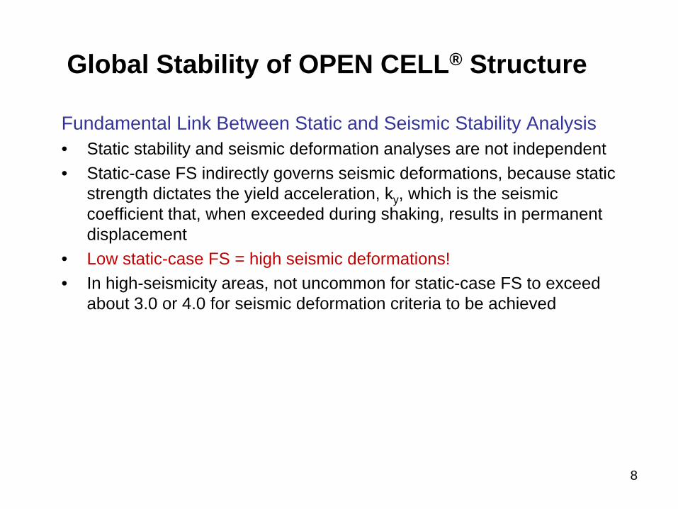
Fundamental Link Between Static and Seismic Stability Analysis • Static stability and seismic deformation analyses are not independent • Static-case FS indirectly governs seismic deformations, because static
strength dictates the yield acceleration, ky, which is the seismic coefficient that, when exceeded during shaking, results in permanent displacement
• Low static-case FS = high seismic deformations! • In high-seismicity areas, not uncommon for static-case FS to exceed
about 3.0 or 4.0 for seismic deformation criteria to be achieved
8

• (Undrained) Intact strength, su Peak undrained strength of an undisturbed, intact sample • (Undrained) Remolded/fully-softened strength, su,rem
Peak undrained strength of a remolded, fully softened, fully weathered, or fully deaggregated cohesive soil
Example: Dallas levees subject to strength loss due to in-place weathering • (Undrained) Residual strength, sur
Minimum strength mobilized under very large displacements when shear-induced excess pore-water pressures and shear stresses are constant; under drained conditions, the soil arrives at same final water content and void ratio, regardless of initial state
• Sensitivity, St
Ratio of undisturbed, intact strength to remolded strength, both of which are peak strengths mobilized at low strains/displacements
Definitions and Notation
9

Definitions and Notation (cont.)
Residual Friction Angle, φ’r (deg)
Fully
Sof
tene
d Fr
ictio
n An
gle,
φ’ (
deg)
Undrained residual strength discussed more later
10

• (Undrained) Cyclic strength, su,cyc
Undrained strength observed under cyclic load application (if failure occurs) or the monotonic strength observed immediately following cyclic loading (e.g., post-cyclic DSS test)
• Cyclic degradation/softening Undrained strength loss attributed to generation of excess pore-water pressures
and strain induced by cyclic load application (typically under relatively small shear strain magnitudes)
• Cyclic degradation and mobilization of undrained residual strength of clay are different modes of strength loss, but mechanisms that may occur simultaneously during seismic shaking if permanent deformations are taking place
Definitions and Notation (cont.)
11

Previous Characterization
Ulery and Updike (1983), Updike and Carpenter (1986) • Geologic characterization
o Identification and definition of various facies of Bootlegger Cove Formation
o Characterization of intrinsic soil properties (e.g., soil consistency) o Geologic maps/profiles
Reproduced from Updike (1986)
Facies F.IV: “Silty clay and clayey silt with silt and fine sand lenses” Facies F.I: “Clay with very minor amounts of silt and sand”

Previous Characterization (cont.)
Terracon (2004) Preliminary Engineering Site Investigation • Incremental load consolidation • Stress History and Normalized Soil Engineering Properties (SHANSEP)
o Direct simple shear (DSS) o Triaxial compression (CIUC)
• Cone penetration test (CPTu) soundings o Piezocone profiling of Bootlegger Cove clay for stress history and
undrained strength characterization • Prediction of undrained strength by modified Cam-Clay model (i.e.,
critical state soil mechanics)
• Primary limitations: limited test data in North Extension, no test data in Barge Berth
13

Exploratory Soil Boring Locations in Barge Berths and North Extension Project Areas 14

Previous Characterization (cont.)
Stress History Interpretation Based on IL Consolidation, Combined TXC-MCC
Pre-Construction OCR
15

Previous Characterization (cont.)
Peak Effective Friction Angle Based on CIUC
Peak Effective Friction Angle, φ’ Design: 27 degrees Reasonable selection given agreement between measured DSS undrained strength ratios and MCC predictions (based on 27 deg); friction angle lower than other reported values Regression: 29 degrees
Design
Regression
16
Previous Characterization (cont.)
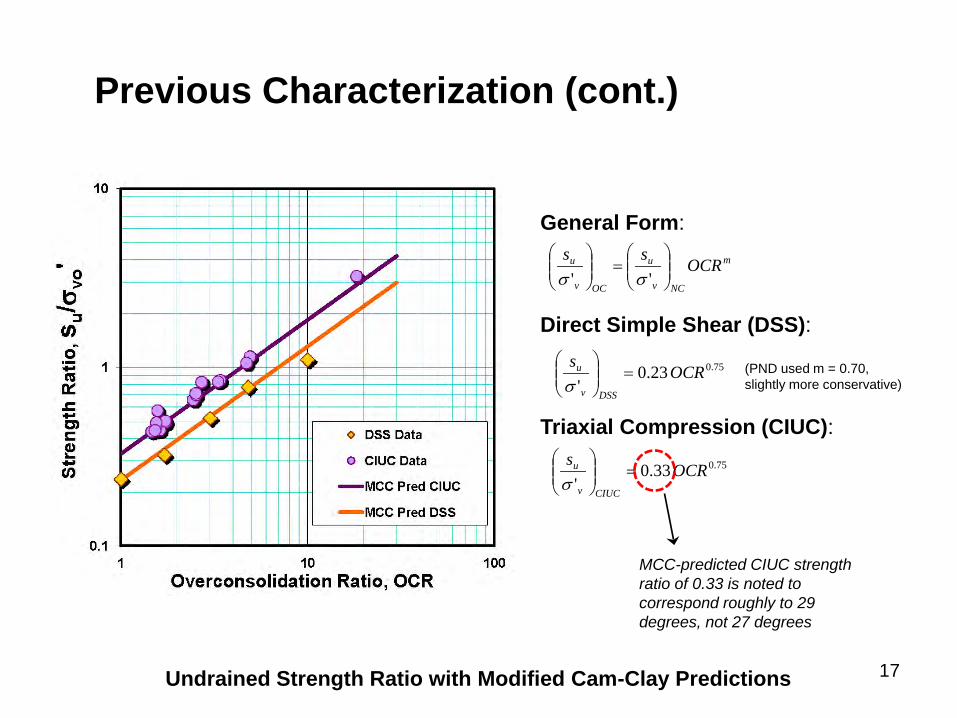
Undrained Strength Ratio with Modified Cam-Clay Predictions
General Form: Direct Simple Shear (DSS): Triaxial Compression (CIUC):
m
NCv
u
OCv
u OCRss
=
'' σσ
75.0 23.0'
OCRs
DSSv
u =
σ
75.0 33.0'
OCRs
CIUCv
u =
σ
(PND used m = 0.70, slightly more conservative)
17
MCC-predicted CIUC strength ratio of 0.33 is noted to correspond roughly to 29 degrees, not 27 degrees

Notes about Modified Cam-Clay Predictions
Direct Simple Shear (DSS):
( )Λ
=
2
2'OCRMCIUCs c
v
u
σ( ) Λ= OCR 2
'sin'
φσ
DSSs
v
u
Triaxial Compression (CIUC):
CS CC - 1 where, =Λ'sin - 3'sin 6 where,φφ
=cM
Variation of undrained strength ratio with triaxial compression effective friction angle for isotropic and K0 conditions At φ’ = 30 deg, difference is 16 percent Discussed further later Wroth and Houlsby
0.0
0.1
0.2
0.3
0.4
0.0 0.1 0.2 0.3 0.4 0.5 0.6 0.7 0.8sinφ'
s u/ σ
vo' N
C (D
SS)
AGS PlasticAmherstAriakeBootleggerBothkennarBoston BlueCowdenHackensack James BayMexico CityOnsoyPorto TollePortsmouthRissaSan FranciscoSilty HoloceneWroth (1984)
su/σvo'NC (DSS) =½sinφ'
Design
Field condition?
18 Data courtesy of Paul Mayne

Notes about Modified Cam-Clay Predictions
Adequacy of CIUC MCC approach demonstrated by comparing undrained strength ratios (measured and predicted) for a wide range of different natural clays. Slope of comparison shows less than 5 percent difference.
Data courtesy of Paul Mayne 19

Previous Characterization (cont.)
Facies F.IV
Facies F.I
TB-54 (CPT-26) in North Extension 1 (next to BH-003-12)
20

Previous Characterization (cont.)
Estimating Preconsolidation Stress Using Piezocone Measurements
After converting preconsolidation stress to OCR, can input into SHANSEP equation(s) to estimate undrained strength for various shearing modes (e.g., DSS, TXC) Note: 0.33 doesn’t seem to apply to north end or very south end of site; lower value indicates higher qt
21

Previous Characterization (cont.)
PND (2010) • Incremental load consolidation (results shown later) • Monotonic triaxial strength testing by DOWL
o Loading rates much too fast (60 times ASTM standard) and therefore disregarded as having little value (general consensus in the record)
• Cyclic DSS testing by MEG Consulting Zapata-Medina (2012) • Doctoral dissertation published at Northwestern University • Incremental load consolidation (results shown later) • Stress-path testing
o Stress paths based on stress conditions from numerical modeling o Focused on effects of construction-induced stresses on dynamic
behavior of clay
22

Due Diligence Investigation 2
Objectives • Characterize the undrained shear strength ratios for triaxial
compression (CAUC) and direct simple shear (DSS) shearing modes • Identify cyclic softening of Bootlegger Cove clay under cyclic load
application • Investigate post-peak strength reduction occurring at large shear
displacements under constant volume conditions • Identify potential spatial variation in geotechnical properties at Port site Scope • Collect intact samples of Bootlegger Cove clay • Laboratory testing:
o Consolidation o Monotonic triaxial compression (CAUC) and DSS testing o Cyclic and post-cyclic DSS testing o Drained and constant volume ring shear testing
23

Exploratory Drilling and Soil Sampling
Exploratory Drilling • Five soil borings in DBB, WBB, NE1, and NE2 • Principal objective to recover nominal 3- and 5-inch samples for
laboratory testing Undisturbed Soil Sampling • Undisturbed sampling of very stiff clay is difficult • Attempted to minimize disturbance
o Mud rotary drilling methods o Gregory Undisturbed Samplers (GUS) o Modified Shelby tubes (zero inside clearance)
24

Exploratory Soil Boring Locations in Barge Berths and North Extension Project Areas
Suitability Study Area
New Borings
25

Exploratory Drilling at Port of Anchorage (Set-Up with Two Rigs in North Extension 1) 26

5-inch Shelby Tube Samples: Drilling Hole in Thin-Walled Tube to Release Vacuum Created by GUS
27

Radiography (Gamma-Ray Scans) to Investigate Sample Quality and Select Test Samples 28

Stress History
Estimation of Preconsolidation Stress • Graphical techniques (e.g., Casagrande, Becker, Pacheco Silva) giving
unreasonably-high values of preconsolidation stress • Resolved to use Boone (2010) method
o “The initial part of the test curve represents only recompression of the swelling and disturbance associated with sampling, specimen preparation, saturation, and test set-up.”
o “Once the applied effective stress is equal to the in situ vertical stress, the void ratio should be representative of the in situ void ratio, ev0, excluding the potential for significant sample disturbance.”
o Preconsolidation determined as intersection of virgin compression line (VCL) and line drawn through point (σ’v0, ev0 = e0) with slope equal to CS based on unload-reload curves
Recall: (1) modified Shelby tubes with zero inside clearance restricted swelling; (2) very short duration between sample extrusion and placement in sample ring
29

Stress History (cont.)
Example: BH-003, ST-3 σ’vp = 360 kPa = σ’v0 Note 1: when VCL is “left” of σ’v0 at e0, σ’vp assumed to be σ’v0 (normally consolidated) Casagrande construction technique, by inspection, would give preconsolidation stress around 1,000 kPa (145 psi) Note 2: average Λ = 0.79
Disturbance effect
(σ’v0,e0)
30

Stress History (cont.)
Characterization of Stress History
• New tests confirm previous preconsolidation stress profile is reasonable and was adopted for this study
• Stress history appears to be uniform across the Port site
31

Peak Effective-Stress Shear Strength
32
Peak Effective Friction Angle, φ’, Based on CIUC and CAUC • Recall other work:
o Lade (1985) CIUC: 29 degrees o Terracon (2004) CIUC: 29 degrees (27 degrees used for design) o Zapata-Medina (2012): 28 to 31 degrees (30 degrees for modeling;
match observed in PLAXIS simulation of laboratory tests) o CH2M HILL (2012): 30 degrees; data show around 29 degrees
(higher value selected, in part, based on fit of MCC predictions of undrained strength ratios with measured strengths)
Effective Friction Angle, φ’, Based on DSS • Not recommended by Ladd (1980’s), but… • 30 degrees seems appropriate based on plots of shear stress vs.
effective vertical stress (maximum obliquity)

Peak Effective-Stress Shear Strength (cont.)
33 Peak Effective Friction Angle Based on New CAUC
Dashed line:
(CH2M HILL) (Terracon)
(maximum obliquity)

Peak Effective-Stress Shear Strength (cont.)
34
“Sensitivity and geotechnical properties of Bootlegger Cove clay” Mitchell, Houston, and Yamane
CIUC Tests on BCC: “Effective friction angle of shearing resistance φ’ was found to vary with liquid limit (LL) as shown. This decrease of φ’ with increase in LL is consistent with results for other clays (Bjerrum, 1961).”
Mean: 38 Std Dev: 6.5 n = 25
POA Liquid Limit Results

Peak Undrained Shear Strength
General Approaches to Undrained Shear Strength Characterization • Measure DSS and CAUC (TXC) undrained strength ratios at different OCRs • Use effective friction angle to estimate DSS and CAUC undrained strength
ratios based on modified Cam-Clay model • Same methods as used by Terracon (2004) Stress History and Normalized Soil Engineering Properties (SHANSEP) • Samples “reconsolidated” past in situ preconsolidation stress and then
unloaded to achieve overconsolidated condition • Purpose of stress-path loading and unloading is to remove disturbance
effects Recompression Technique • Samples “recompressed” to varying stress levels • Sample OCR determined as in-situ σ’vp / σ’vc
• May provide higher strength/modulus (SHANSEP is typically conservative) • Results for this method depend heavily on sample quality/disturbance!
35

Peak Static Undrained Shear Strength (cont.)
Direct Simple Shear (DSS) Testing • 30 DSS tests conducted (15 SHANSEP, 15 Recompression) • OCR ranges from 1 to about 8.5 • Average measured (su/σ’vc)NC: 0.277 (OCR = 1 tests only) • MCC prediction based on 30 deg: 0.25 Triaxial Compression (CAUC) Testing • 19 CAUC tests conducted (15 SHANSEP, 4 Recompression) • OCR ranges from 1 to about 9 • Average measured (su/σ’vc)NC: 0.35 (both OCR = 1 tests) • [Wroth CK0UC] MCC prediction based on 30 deg: 0.30, but… • MCC prediction corrected to 0.34, as discussed
36

Peak Static Undrained Shear Strength (cont.)
(Terracon)
37

Peak Static Undrained Shear Strength (cont.)
Modified Cam-Clay Prediction of CAUC Undrained Shear Strength • For φ’ = 30 deg, (su/σ’vc)NC based on Wroth is 0.30 for CK0UC
• Testing of other natural clays has shown this to be conservative (i.e., undrained strength ratio not very sensitive to φ’)
• Correction of 1.1294 used to increase CAUC strength ratio from 0.30 to 0.34.
• Strength ratio of 0.34 compares with 0.35 for CIUC, just slightly more conservative.
Data courtesy of Paul Mayne
1:1
38

Cyclic Behavior
Bender Element Shear Wave Velocity • Conducted on 12 of 16 samples after consolidation, before cyclic
loading (Vs = 1150 to 1350 ft/s) – agree with field Vs measurements Cyclic DSS (CyDSS) Testing • Stress-controlled tests • Facies F.IV and F.I • OCR = 1, 2 • Each of four test series including four CSR values • One test series including a static shear bias Post-cyclic DSS Testing • Immediately after cyclic loading (i.e., no drainage allowed), each
sample sheared monotonically
39

Cyclic Behavior (cont.)
40
Example CyDSS data/results from most recent testing program
CyDSS test results in
PND (2010) show similar response
Increasing CSR
0.25
0.20
0.15
0.10

Cyclic Behavior (cont.)
41

Cyclic Behavior (cont.)
42

Cyclic Behavior (cont.)
43
Thiers and Seed (1969). “Strength and stress-strain characteristics of clays subjected to seismic loading conditions.”
“It is evident that the sensitivity of a soil is not a good indicator of its susceptibility to strength loss
under cyclic loading conditions.”
St = 8 – 10 St = 20 – 30
St = 1 – 2
“Low” sensitivity of the Bootlegger Cove clay
cannot be used as justification for ignoring potential strength loss during seismic event!
Consider effects of excess pore-water
pressure and cyclic strain on cyclic strength

Cyclic Behavior (cont.)
44
Modulus reduction representative of a low-plasticity clay
G taken as secant
modulus for first cycle of loading on each
specimen; Gmax from bender element shear
wave velocity

Cyclic Behavior (cont.)
45
Degradation parameter also representative of a low-plasticity clay, referencing Tan and Vucetic (1989) and Vucetic (1994)
Cyclic stiffness degradation:
δ = G / GN = N-t
where, t = degradation parameter

Post-Cyclic Shear Strength (cont.)
Idriss (1985). “Evaluating seismic risk in engineering practice.”
Variation of post-cyclic undrained strength with excess pore-water pressure ratio induced during cyclic load application
Li et al. (2011): “Excess pore-water pressure continuously increases with the number of cycles, and no inflection appears, regardless of cyclic failure. Water pressure lag behaves seriously if the clay sample is at high frequency or large cyclic stress conditions. Thus, the accumulative pore-water pressure is not suggested to estimate the cyclic failure for natural clays.”

Post-Cyclic Shear Strength (cont.)
47
Following Thiers and Seed (1969) Idriss (1985), Moriwaki (1985), Idriss (2010)
Under high-displacement conditions, one must
consider use of undrained residual strength as
governing resistance against [slope] movements
6-inch delineation based on observation that ground movements during 1964
earthquake were either very large or less than about 6 inches
Post-cyclic test data by MEG for PND (2010) design

Undrained Residual Strength
Current Ring Shear Testing Program • Constant volume (i.e., undrained) tests at σ’vc = 100, 200, 300, 400, 600 kPa
(OCR from 1 to about 4.5) • Constant stress (i.e., drained) tests at σ’vc = 100, 400, 600 kPa; ASTM • One “faster” test under constant volume conditions, σ’vc = 400 kPa • Two “healing” tests at σ’vc = 400 kPa (undisturbed and remolded) Other Ring Shear and Back-Analyses Involving Bootlegger Cove Clay • Port MacKenzie constant volume ring shear tests on BCC • Fourth Avenue landslide Bootlegger Cove clay ring shear tests • Back-analyses
o Fourth Avenue o L Street o Government Hill
48 Ring shear device only apparatus to measure strength at very large strains

Undrained Residual Strength (cont.)
49 Constant Volume Ring Shear Test Apparatus
Load cell measures the change in vertical stress to maintain constant volume

Undrained Residual Strength (cont.)
Port of Anchorage Bootlegger Cove clay
select test results plotted over the test results from
Fourth Avenue Bootlegger Cove clay
Under constant volume
conditions, both materials show
considerable post-peak strength reductions
resulting from excess pore-water pressure
“generation”
POA Constant Volume Ring Shear Test Results, Comparison with Fourth Avenue

Undrained Residual Strength (cont.)
51 Constant Volume Ring Shear Tests
Undrained residual strength at large displacements
about 10 to 20% of NC peak
Port MacKenzie Bootlegger Cove Clay Ring Shear Test Results from 2001
ST-4
ST-7
ST-11

Modified from Idriss (2010)
Constant volume ring shear tests conducted on
Bootlegger Cove clay from Fourth Avenue slide area (inside and outside slide mass), Port MacKenzie, and Port of Anchorage
Large-displacement,
undrained shear behavior the same at all
three locations!
52

Undrained Residual Strength (cont.)
Variation of normalized undrained shear strength ratio with ground surface
displacement
Based on back-analyses of landslides occurring
during the 1964 earthquake: Fourth
Avenue, L Street and Government Hill
Characterization of Displacement Softening for Estimating Seismic Deformation
Stark and Contreras (1998),
CH2M HILL Recommendation
Idriss (1985)
How are ring shear results and back-analyses used?

Undrained Residual Strength (cont.)
Example Newmark Seismic Displacement Analysis with Updated Shear Strength
How are ring shear results and back-analyses used?
OLE CLE
Michoacan EQ Record
Determined from Shear Strength
Displ. = 0.4 inch Displ. > 3 feet
Mobilization of peak strength
Recall observation that ground movements during 1964 earthquake were either very small or very large
Strength reduction
54

Undrained Residual Strength (cont.)
Why are the 1964 landslides so commonly associated with the sensitive facies of BCF?
Reason 1: Sensitive clays may exhibit lower undrained strength ratios and may, therefore, be more susceptible to ground failure
Reason 2: Sensitive clays may mobilize peak strength at lower strains or displacements and, thus, post-peak strength reductions will occur sooner
Increasing sensitivity
Lower strength
Increasing sensitivity Lower
failure strain
A potential shear plane may more likely develop in a sensitive clay (if present) because of lower shear strength and more brittle behavior (i.e., “card-house” structure), not solely due to the sensitivity of the clay. This observation does not preclude the same
failures in “low sensitivity” clays of similar peak undrained shear strength and sufficiently high shear loading!
Houston and Mitchell(1969) Houston and Mitchell(1969)

Undrained Residual Strength (cont.)
Example Constant Volume Ring Shear Test Results on Different Clays
Soil Deposit
LL
PL
Sensitivity
su/σ’v
sur/σ’v
sur/su
Bootlegger Cove clay, inside Fourth Ave. landslide, Anchorage, Alaska
40 20 3 – 11 0.28 0.07 0.25
34 19 0.28 0.07 0.25
36 21 0.24 0.06 0.25
38 21 0.23 0.06 0.26
39 20 0.23 0.06 0.26
Bootlegger Cove clay, outside Fourth Ave. landslide, Anchorage, Alaska
42 23 3 – 11 0.31 0.11 0.35
40 21 0.32 0.10 0.31
42 23 0.31 0.11 0.35
41 22 0.30 0.11 0.37
Drammen clay, Danvik-gate, Drammen, Norway
47 23 4 – 10 0.27 0.09 0.33
48 24 0.22 0.11 0.5
47 25 0.20 0.11 0.55
Bootlegger Cove clay, Port of Anchorage, Anchorage, Alaska
34 20 1 – 3 0.25 0.03 – 0.16 0.16 – 0.50
56

Undrained Residual Strength (cont.)
Example Constant Volume Ring Shear Test Results on Different Clays
Soil Deposit
LL
PL
Sensitivity
su/σ’v
sur/σ’v
sur/su
Bootlegger Cove clay, inside Fourth Ave. landslide, Anchorage, Alaska
40 20 3 – 11 0.28 0.07 0.25
34 19 0.28 0.07 0.25
36 21 0.24 0.06 0.25
38 21 0.23 0.06 0.26
39 20 0.23 0.06 0.26
Bootlegger Cove clay, outside Fourth Ave. landslide, Anchorage, Alaska
42 23 3 – 11 0.31 0.11 0.35
40 21 0.32 0.10 0.31
42 23 0.31 0.11 0.35
41 22 0.30 0.11 0.37
Drammen clay, Danvik-gate, Drammen, Norway
47 23 4 – 10 0.27 0.09 0.33
48 24 0.22 0.11 0.5
47 25 0.20 0.11 0.55
Bootlegger Cove clay, Port of Anchorage, Anchorage, Alaska
34 20 1 – 3 0.25 0.03 – 0.16 0.16 – 0.50
Mobilization of peak strength the cause of seismic ground
failure…no post-peak strength loss, if peak strength not
mobilized
Stable during 1964 earthquake
57
(DSS) (CVRS)
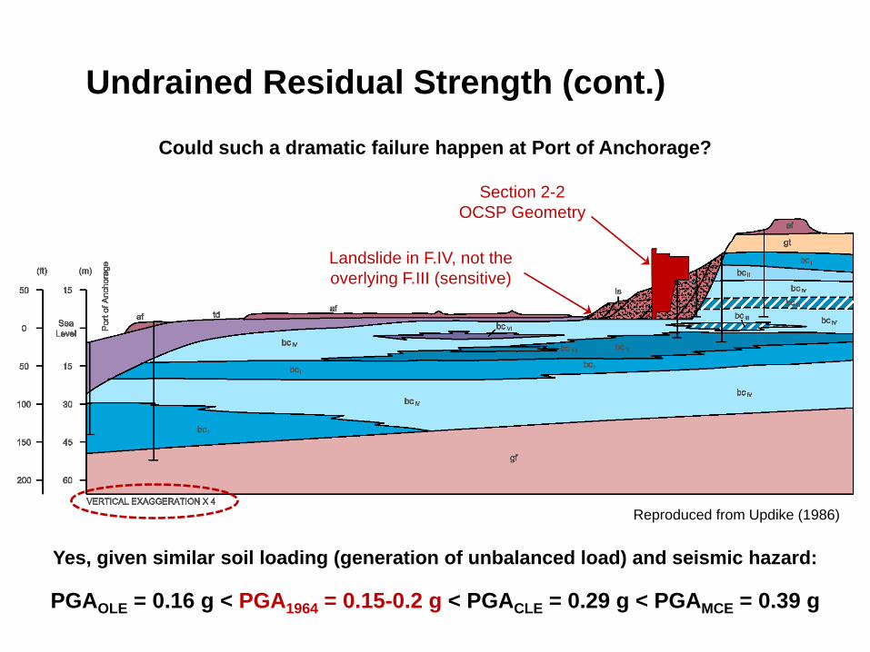
Undrained Residual Strength (cont.)
Could such a dramatic failure happen at Port of Anchorage?
Section 2-2 OCSP Geometry
Reproduced from Updike (1986)
Yes, given similar soil loading (generation of unbalanced load) and seismic hazard:
Landslide in F.IV, not the overlying F.III (sensitive)
PGAOLE = 0.16 g < PGA1964 = 0.15-0.2 g < PGACLE = 0.29 g < PGAMCE = 0.39 g

Undrained Residual Strength (cont.)
Could such a dramatic failure happen at Port of Anchorage?
Section 2-2 OCSP Geometry
Fourth Avenue failure profile from Stark and Contreras (1998)
Yes, given similar soil loading (generation of unbalanced load) and seismic hazard:
PGAOLE = 0.16 g < PGA1964 = 0.15-0.2 g < PGACLE = 0.29 g < PGAMCE = 0.39 g

Undrained Residual Strength (cont.)
Could such a dramatic failure happen at Port of Anchorage?
SAFE
FAIL
Chart from Wilson (1967)
Whether a slope founded on Bootlegger Cove clay
was observed to move was a function of slope height
and slope inclination
OCSP at POA
60

Shear Strength Comparisons
61
Terracon (2004), PND (2008) CH2M HILL (2012)
70.0 23.0'
OCRs
DSSv
u =
σ
75.0 33.0'
OCRs
TXCv
u =
σ
deg27'=φ
79.0 25.0'
OCRs
DSSv
u =
σ
79.0 34.0'
OCRs
TXCv
u =
σ
deg30'=φ
Major Difference: Newmark analyses for estimating seismic deformation of OPEN CELL system at Port of Anchorage are considering the post-peak strength loss (about 70% ) due to excess pore-water pressures generated under large displacements (also difference in limit-equilibrium critical failure surface shape/selection) Consequence: Inadequate safety factor and significantly higher displacements estimated for CLE and MCE design events
( 9%)
( 3%)
( 13%)

Conclusions
62
Bootlegger Cove Clay Characterization • Stress history interpretation similar to that assumed for design of North
Expansion projects • Peak strengths (effective-stress friction angle and undrained strength
ratios) slightly higher than assumed for design • Cyclic degradation due to cyclic load application at higher CSR values
results in reduced shear modulus and post-cyclic undrained shear strength • Very large shear displacements under constant volume conditions result in
significant post-peak undrained strength reductions Implications for Static and Seismic Stability • Inadequate static-case FS and excessive seismic deformations still
observed • Shear behavior of Bootlegger Cove clay at Port of Anchorage similar to
behavior of the material at Port MacKenzie and Fourth Avenue • Analyses indicate instability due to BCF loading and seismic shaking (both
similar to conditions at Fourth Avenue)

References
• Becker, D., Crooks, J., Been, K., and Jeffries, M. (1987). “Work as a criterion for determining in situ and yield stresses in clays.” Canadian Geotechnical Journal, NRC Research Press, Vol. 24, p. 549-564.
• Boone, S. (2010). “A critical reappraisal of “preconsolidation pressure” interpretations using the oedometer test.” Canadian Geotechnical Journal, NRC Research Press, Vol. 47, p. 281-296.
• Casagrande, A. (1936). “The determination of the preconsolidation load and its practical significance.” Proceedings, 1st International Soil Mechanics and Foundation Engineering Conference, Vol. 3, Graduate School of Engineering, Harvard University, Cambridge, Mass., p. 60-64.
• Houston, W., and Mitchell, J. (1969). “Property interrelationships in sensitive clays.” Journal of the Soil Mechanics and Foundation Division, ASCE, Vol. 95, SM4, p. 1037-1062.
• Idriss, I.M. (2010). “Contributions of field case histories to geotechnical earthquake engineering.” The 2010 Peck Lecture, Presented at GeoFlorida, ASCE, West Palm Beach, Florida.
• Lade, P., Updike, R., and Cole, D. (1985). Cyclic Triaxial Tests of the Bootlegger Cove Formation, Anchorage, Alaska. U.S. Geological Survey Bulletin 1825, Public-data File 85-30.
63

References (cont.)
• Li, L., Dan, H., and Wang, L. (2011). “Undrained behavior of natural marine clay under cyclic loading.” Ocean Engineering, Elsevier, Vol. 38, p. 1792-1805.
• Mitchell, J., Houston, W., and Yamane (0000). “Sensitivity and geotechnical properties of Bootlegger Cove clay.”
• Moriwaki, Y., Vicente, E., Lai, S., and Moses, T. (1985). A Re-Evaluation of the 1964 “L” Street Slide. Final report, State of Alaska Department of Transportation and Public Facilities, Division of Planning, Research Section, April.
• Pacheco Silva, F. (1970). “A new graphical construction for determination of the preconsolidation stress of a soil sample.” Proceedings, 4th Brazilian Conference of Soil Mechanics and Foundation Engineering, Rio de Janeiro, Brazil, Vol. 2, No. 1, p. 225-232.
• Wilson, S. (1967). “Landslides in the City of Anchorage.” In The Prince William Sound, Alaska, Earthquake of 1964 and Aftershocks, U.S. Department of Commerce Publication 10-3, Vol. 2.
• Wroth, C. and Houlsby, G. (1984). “Soil mechanics – Property characterization and analysis procedures.”
• Zapata-Medina, D. (2012). Evaluation of Dynamic Soil Parameter Changes Due to Construction-Induced Stresses. Doctoral dissertation submitted to Graduate School at Northwestern University, August. 64

Attachment F
Support from Dr. Paul Mayne


PoA Geotechnical Lab Test Review by GT (02 November 2012) Page 1 of 3
Geosystems Engineering Program School of Civil & Environmental Engrg
Georgia Institute of Technology Atlanta, GA 30332-0355
Ph: 404-894-2282 and fax-2281 http://www.ce.gatech.edu
02 November 2012 Mark Thompson CH2M-Hill 1100 112th Avenue NE Bellevue, WA 98004 Email: [email protected]
Re: Geotechnical Review: Laboratory Testing of Bootlegger Cove Formation at Port of Anchorage CH2M-Hill Project Number 427856.01.06; GTRC Project 2006T32 Dear Mark, This final report relates to the recent series of laboratory tests conducted for the Port of Anchorage Expansion project. This is an updated version since our draft report that was issued on 30 August 2012. Since then, we have received most of the cyclic simple shear strength results and constant volume ring shear data for review. LABORATORY TEST DATA This final report documents the summary of our review concerning the laboratory testing and interpretation on the Bootlegger Cove Formation (BCF) clay for the Port of Anchorage (PoA) intermodal expansion suitability study. As outlined in the original Statement of Work, a new set of undisturbed tube samples of the clay were procured at the site using field rotary drilling operations. Selected samples were transported to MEG laboratories for testing which included: index, consolidation, monotonic triaxial compression tests, bender element measurements of shear wave velocity on specimens, and series of both static and cyclic direct simple shear testing (DSS). Also, selected samples were sent to the University of Illinois - Urbana - Champaign (UIUC) for performing constant volume (undrained) ring shear tests, as well as limited set of drained ring shear tests. A majority of the monotonic triaxial test series, related index tests, and CRS consolidation data were available in June and July of 2012. In September 2012, the majority of results from the cyclic simple shear test series by MEG labs were sent for review. We also received most of the data from the constant volume ring shear tests performed by UIUC in a 30-page report (dated 22 Oct 2012) . Several documents pertaining to the analysis of lab data by CH2M were provided to us. These involved several spreadsheets with both raw and processed data, as well as two sets of Powerpoint slides: one entitled "Static and Dynamic Shear Strength of Bootlegger Cove Clay at Port of Anchorage" prepared by your office (dated 30 August 2012) and a second set of 19 slides (29 Oct 2012). Prior data collected in the preliminary 2004 study by Terracon and Gregg In-Situ were also considered, as well as later data obtained by GeoEngineers, PND, and DOWL (2008). Moreover, a recent dissertation (Zapata-Medina, August 2012) at Northwestern University also provided supplementary new data on BCF clay for consideration, including sets of triaxial compression and extension tests, CRS consolidation data, and cyclic strength testing. Other documents supplied for consideration included portions of a Site Response Analysis Report prepared by Dr. Y. Hashash of UIUC (dated 14 July 2010); and an excerpt 10-slide PPT set (dated 02 Oct 2012) from CH2M regarding the calculated factors-of-safety (FS) concerning stability of the current open-cell sheet pile wall design that was under construction at the PoA. The Site Response Report gives expected cyclic stress ratios (CSR) at 0.12,

PoA Geotechnical Lab Test Review by GT (02 November 2012) Page 2 of 3
0.19, and 0.26 for operating level earthquake (OCE), credible level earthquake (CLE), and maximum credible earthquake (MCE), respectively, within the BCF clay layer. SCOPE OF WORK Our scope of services on this project involved four tasks: (1) review of the laboratory testing program; (2) review of laboratory results; (3) communication; and (4) summary review deliverables, including this report. Most of these tasks were accomplished using email memoranda, electronic attachments, and teleconferences. These are briefly discussed in subsequent paragraphs. Task 1. For the laboratory testing program, GT reviewed and concurred with the outlined agenda that included: • Collect intact samples of Bootlegger Cove clay • Laboratory testing:
One-dimensional consolidation Monotonic triaxial CAUC and DSS testing Cyclic and post-cyclic DSS testing Drained and constant volume ring shear testing
General discussions on these topics were made during emails and phone conversations in April and May of 2012. Task 2. Review of laboratory test data analysis Sampling: In earlier series of undisturbed sampling at PoA, common Shelby tubes and/or piston type samplers were used. Herein, CH2M-Hill utilized larger GUS samplers in an attempt to procure higher quality samples and mitigate effects of sample disturbance. Consolidation: Previous series of consolidation tests involved incremental-load (IL) type with stepped loading. Herein, consolidation series of constant-rate-of-strain (CRS) with continuous loading were attempted in hopes of securing more pronounced and definitive evaluations of the effective yield stress (σp'), more commonly termed the preconsolidation stress. In fact, sample disturbance remained an issue during our discussions and CRS type testing appeared to exhibit some new difficulties in producing "expected" curves, thus directing CH2M-Hill to revamp the program slightly and substitute the some of the consolidation series with IL type in lieu of the CRS versions. Shear Tests: For the triaxial compression (TXC) and direct simple shear (DSS) strength testing, the use of both SHANSEP procedures (Ladd 1991) and recompression techniques (e.g. Ladd & DeGroot 2003) were applied to series of specimens. While the reviewer originally recommended the latter procedure, it turns out that perhaps the unfortunate issues of sample disturbance prevailed at PoA and in hindsight, the SHANSEP approach proved to be a more reliable procedure in producing undrained shear strength data on the BCF clays. The evaluations shown in Mark Thompson's PPT indicate relationships between the normalized undrained strength ratios (su/σvo') and overconsolidation ratio (OCR) for both TXC (CAUC) and DSS series that are compatible with the earlier Terracon study (2004) and the recent NWU study (2012). The use of Modified Cam Clay (MCC) in organizing these lab data also seems validated. The NWU data also included series of triaxial extension tests (TXE) or CAUE mode. The effective stress strength envelope was assessed in Mark Thompson's PPT with the following parameters: c' = 0 and φ' = 30º. The earlier study by Terracon (2004) gave a more conservative set of values (c' = 0 and φ' = 27º) while the NWU study suggested slightly higher values of around φ' = 28º. Also, a much earlier study by Lade et al. (1985) indicated: c' = 0 and φ' = 28º. It is noted that the interpretation of effective strength failure envelopes of soils can be made on the basis of several criteria, including: (a) maximum deviator stress; (b) maximum obliquity, i.e. (σ1'/σ3') ratio; and (c) values taken at 15% strain. The corresponding values of the effective cohesion intercept (c') and effective friction angle (φ') may be adjusted accordingly. Notably, criterion (b) often gives slightly larger values of φ' compared with criterion (a). Cyclic Tests: The series of cyclic tests appear to agree with prior data collected on the BCF clays, as well as results from other clays tested under cyclic DSS (e.g., Azzouz et al. 1989; Pestana et al. 2000, Boulanger & Idriss, 2007). As the portion of the clay at the base behind the wall is heavily loaded due to large thickness of fill, the natural

PoA Geotechnical Lab Test Review by GT (02 November 2012) Page 3 of 3
preconsolidation is forced towards a nearly normally-consolidated state, close to OCR = 1. The static undrained strength ratio for the DSS mode at this condition is S = (su/σvo')NC = 0.25. At high levels of cyclic loading, the applied CSR = (τcyclic/σvo') = 0.19 at the CRE is at 76% of static strength, thus significant positive porewater pressures can be generated and the accumulation of cyclic shear strains can occur at these magnitudes of loadings. At the higher MCE level, the CSR could force the clay through its peak strength, thus resulting in strain softening behavior. The level of sustained strength following peak would depend upon the numbers of cycles of loading (i.e. duration of the earthquake). Ring Shear Tests: The use of constant volume ring shear tests is a specialized series of tests that were used to investigate post peak softening of the BCF clay. In these data, the values of peak undrained strengths normalized to effective overburden stress level appear comparable to those determined by static DSS test series. The subsequent large strain shearing after peak resulted in lower strengths, with magnitudes dependent upon the amount of displacement. Task 3: Correspondence Information between CH2M-Hill and GT was routinely provided using email memoranda with attachments provided in Excel, Powerpoint, Word, JPEG, and/or PDF formats, depending upon the specific documents. A number of phone conversations and/or teleconferences were held to discuss various matters at critical times during the project schedule. Of recent, a teleconference call was held with Don Anderson and myself on 12 Oct 2012 and another with both Drs. Anderson and Thompson of CH2M-Hill and myself on 31 Oct. 2012 to discuss the final aspects of this project. Task 4: Deliverables. Several email memos were issued during planning and analysis stage of the project. In particular, this final report serves as a summary of information, interpretation, and conclusions made on the PoA project, based on the summary test data and synthesis of results. Sincerely
Paul W. Mayne, PhD, P.E. Professor - Geosystems Engineering Group School of Civil & Environmental Engineering Office: IPST Room 225 Georgia Institute of Technology Atlanta, GA 30332-0355 Phone: 404-894-6226 Fax: 404-894-2281 Email: [email protected] Website: http://geosystems.ce.gatech.edu ISSMGE TC 102: In-Situ Testing: www.webforum.com/tc16 REFERENCES Azzouz, A.S., Malek, A.M. and Baligh, M.M. (1989). Cyclic behavior of clays in undrained simple shear. Journal of
Geotechnical Engineering 115 (5): 637-657. Boulanger, R.W. and Idriss, I.M. (2007). Evaluation of cyclic softening in silts and clays. Journal of Geotechnical &
Geoenvironmental Engineering 133 (6): 641-652. Pestana, J.M., Biscontin, G., Nadim, F. and Andersen, K. (2000). Modeling cyclic behavior of lightly
overconsolidated clays in simple shear. Soil Dynamics and Earthquake Engineering 19: 501-519.