Embed Size (px)
Citation preview
TECHNICAL NOTE
I.'I )I;irma
)rocec ure 'or~: ierinc s >ear I:es:AJ Harris and PDJ Watson, School of Civil Engineering,
Kingston University, Penrhyn Road, Kingston-Upon
Thames, Surrey, KT1 2EE.
The test procedure given in BS 1377 Part 7 to determine the residualshear strength of a soil using the Bromhead ring shear apparatuscontains a number of procedures that make the test both difficult andtime consuming. A test procedure used at Kingston University since thedevelopment of the Bromhead ring shear apparatus is thereforeproposed. The procedure is in effect a multi-stage test and commonlyresults in a value for the drained residual shear strength within threeworking days. The residual shear strength values obtained have beenfound to be close to those derived from back analyses of slope failures,especially when there is a strong element of bedding control on thelocation of the slip surface and when the back analysis is not undulyaffected by uncertainties in pore pressures and end effects. A review ofalternative uses and test procedures for the Bromhead ring shearapparatus is also included.
1.0Inbwluc5onThe ring shear test was first proposed by A Casagrande as reported byHvorslev (1939).More recent developments include those by Bishop et al.(1971)and Bromhead (1979),whose simplified apparatus (see Fig. 1)usesa thin sample of remoulded soil. It is this design concept that forms thebasis for the test recommended by BS1377(1990).The apparatus has alsobeen further developed for particular investigations notably by Steward&Cripps 1983,Hawkins &Privett 1985,Stark & Eid 1993,and Dewhurst etal, 1996.
The alteration of a soil fabric caused by the formation of a shear zoneor shear surface, results in changes to the strength properties of the soil.The strength of the soil with its original fabric is termed the peakstrength, and its strength under large deformation conditions in a shearzone or on a shear surface is referred to as the residual strength.Conventional triaxial and direct shear box tests do not allow sufficientstrain for the residual strength to be fully developed. These tests can onlybe used if preformed shear surfaces, that have been developed either in
the field or artificiaUy in the laboratory, are carefully aligned in the testapparatus. As this is an extremely time consuming and difficult process,the ring shear apparatus was developed. In this apparatus an annulus ofsoil is sheared by rotation allowing large strains to be readily obtained.
2.0BS1377Rlug shear testPart 7 of BS 1377 classes the ring shear test as a Total Stress Test, whichthe majority of civil engineers assume to be an undrained test. The ringshear test is however a drained test; and although the total and effectivestresses are the same when the sample is drained, some confusion mayarise regarding the soil properties derived from the test. It would appearmore logical, therefore, for the test tobe included in Part 8 of BS1377.
The BS test also includes some procedures that make it difficult andtime consuming. These procedures negate the advantages of thisparticular apparatus, which are simplicity and speed (Hawkins &Privett 1981).Part 7, section 6.4.2.states that the sample should be subjectto a consolidation stage. This is in agreement with the authors, howeverBS1377recommends that the time to 100%primary consolidation (ti~) isdetermined. This would be possible if the sample was of sufficientthickness, however the small thickness of the ring shear sample hasmeant that monitoring of the consolidation stage is inaccurate. Thisproblem can be compounded by the fact that with some soft clays, soilmaybe squeezed out between the confining rings and the upper platen.
Similarly, the use of separate consolidation stages throughout the testgives little additional benefit to the overall result. From the time to 100%consolidation, it is possible to determine the rate of strain at which thesample should be tested. By calculating the correct rate of strain, it canbe ensured that pore pressures dissipate during the test, but thiscommonly results in very slow strain rates. These calculated rates ofstrain are generally too slow as they are based on a drainage path of halfthe sample thickness. However, it is commonly found that the shearsurface forms within 1mm of the upper platen. Hence, the drainage pathis shorter than assumed and the tendency for excess pore pressures todevelop due to shear is reduced. In any event the influence of strain rateon the measured properties can be assessed by raising or lowering thestrain rate and observing the effect on the measured torque. Loweringthe strain rate should result in an increase in the measured torque ifexcess pore water pressures are being generated due to shear. However,it should be noted that high rates of shear may result in disturbance ofthe residual soil fabric (aligned clay particles) with consequent increasein inferred strength.
Problems with the BStest can also result from formation of the shearplane during the initial stage. The test recommends that the shear planeis formed "by using the motor drive or hand wheel (iffitted) to rotate thespecimen by one to five revolutions within a period of approximately 2min". This high shear rate can result in substantial extrusion of thesample, the generation of undrained pore water pressures, whichultimately dissipate, as well as non-fully aligned clay particles. It istherefore recommended that a slow shearing rate is used to complete theformation of this feature correctly (see section 3.2).
To overcome the problems posed by the BSprocedure, the following isrecommended for the small ring shear test, particularly for those using
the Bromhead Ring Shearapparatus.
Pillar for settlement gauge3.0Optimal test procedure
Counterweight Rest for load arm
Rgnre1: Ring shear ayyarnhia eleeaeon and soneinl taronL
IJ ZnLoad hanger
unterghtedding
3.1Sample prepartruon1.The first step is to remould thesoil sample at a moisture contenteither at or lower than the plasticlimit. This is because shearsurface formation is a result ofsoil brittleness, which is morelikely to occur at moisturecontents lower than the plasticlimit.Note: Remoulded specimens arequite adequate for residualstrength determination alone.This is because the development ofa shear surface in a clay soilcompletely changes the soilsinitial fabric in the vicinity of theshear surface. There is thereforelittle or no merit in attempting topreserve such an initial fabric orstructure in the test specimen,unless it is specifically desired to
26 GROUND ENGINEERING JULY 1997
TECHNICAL NOTE
examine the process of shear surface formation.2. The remoulded soil is then kneaded into the sample container withthe fingers, or rammed into position with a wooden spatula, and thesurface trimmed flush with the container by using a palette knife.3. The top loading platen is placed on the sample, and the lever loadingarm placed on this. The bath is then filled with water and the sampleleft to saturate fully.Note: Settlement readings may be taken but squeeze effects tend tomake readings valueless (see earlier comments).
3.2lnlmal shearing1. It is necessary to select an appropriate rate of shear, before shearingcan take place. If high rates of shear are used substantial extrusion ofthe sample can occur. Although a shear surface of sorts is usuallyformed by this rotation, this surface may not have the desiredproperties. This can be either as a result of the generation of undrainedpore water pressures, or because viscous inter particle drag forces haveprevented the formation of an ideal, strongly particle oriented, lowstrain rate, shear surface. Therefore, a slow shearing rate isrecommended to complete the formation of this feature correctly—commonly a rate of 0.048degrees/min is used.2. The first load —for instance 2kg, equivalent to 52kN/m' is applied.Then by using the coarse adjustment, the cross arm is brought intocontact with the proving rings, so that both proving rings mutually meetthe cross arm simultaneously.3. Readings of settlement may be taken at 0, 1, 2, 4, 6, 10, 2030, 45 min andthen at 15 min intervals, to monitor the process of consolidation.Frequency of readings is variable but should be sufficient to ensure thatconsolidation is complete.4. Once consolidation is complete, usually less than one hour afterapplying the load, the machine is switched on and left rotatingovernight. It maybe datalogged, or merely left to run.Note: Taking up "slack" in the system may take a considerable time,which can result in a lag between starting the motor and readings beingrecorded. Careful setting up reduces this lag significantly.5. Readings are taken for 30 min on the following day. If constantreadings are obtained, a constant torque has been obtained in the soil.This indicates that shear-induced pore water pressures, which causechanges in the shear strength of the soil, have dissipated and that a fullyformed residual shear strength surface has been formed.6. The motor is then stopped, and the gauges observed for a further 15min. If the readings are found to drop substantially the shearing ratewas too fast. The soil is therefore still strain rate sensitive, as a resultviscous inter particle drag forces preventing the formation of an idealshear surface (Bromhead, 1992). In this case, it would be necessary torepeat the shearing at a slower rate.Note: This step may be omitted, with the sensitivity check beingcarried out at the highest load stage.
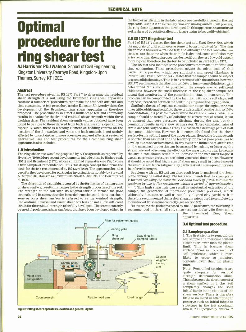
3.3Subsequent load stages1. The load is increased by a further nominal amount, eg 2 kg, on thehanger and shearing re-commenced. It is not necessary to allow thesample to consolidate under the new load as pore pressure dissipation israpid and torque readings indicate whether there are excess porepressures present or not.2. Readings are taken at 0, 2, 4, 6, 10, 15,20 min and at 5 min intervals untilthree readings the same are achieved (see typical test results shown inFig 2).3. Optionally, the motor is stopped and readings taken at 1 min intervalsfor 5min.4. Several more load stages are carried out by repeating steps 1 to 3,finishing with a test on strain rate sensitivity.5. At the end of the final load stage, the torque is released on the sample,using the adjusters on the proving rings.6. The sample is then unloaded to the first load stage and steps 2, 3 and 5repeated.7. The sample is unloaded and the apparatus dismantled carefully. Theshear surface formed in the sample can then be examined.
4.00verall teat cummutttu
4.t Modified tost proceduresSteward & Cripps (1983)modified the Bromhead ring shear apparatus sothat the composition of pore solutions could be altered during shearing.This was to determine if the residual shear strength of the soil wasfound to be sensitive to different pore solutions. Brass nipples wereconnected to the lower plate drainage channels so as to allow the poresolution to be introduced into the system. Sealing screws were thenplaced in the side exit holes and a rubber gasket placed beneath the
Extendedtime in
ie fimt siege
i
Stop rotation if torque held,//resuh is nol strain rate sensitive
Matches first /measured resrduat2
'teadytorque indicatesl
/
drainage completed /Torque removed before/r lf not, repeatdecreasing normal load other load stages
Time axis or rotation seats
I stasas pt-oad
Houre 2:t)ttttoal tost resuns, sttotolueoNootortNI-ttuttuo at outlot tost.
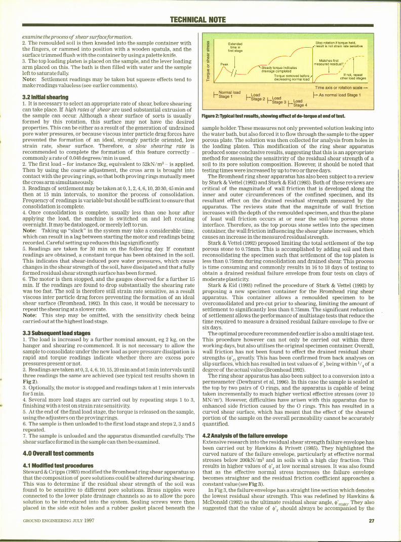
4.2Analysls of the failure envelopeExtensive research into the residual shear strength failure envelope hasbeen carried out by Hawkins & Privett (1985). They highlighted thecurved nature of the failure envelope, particularly at effective normalstresses below 200kN/m'nd in soils with a high clay fraction. Thisresults in higher values of tt', at low normal stresses. It was also foundthat as the effective normal stress increases the failure envelopebecomes straighter and the residual friction coefficient approaches aconstant value (see Fig 3).
In Fig 3, the failure envelope has a straight line section which denotesthe lowest residual shear strength. This was redefined by Hawkins &McDonald (1992) as the ultimate residual shear angle, tt'<~tr They alsosuggested that the value of 4', should always be accompanied by the
sample holder. These measures not only prevented solution leaking intothe water bath, but also forced it to flow through the sample to the upperporous plate. The solution was then collected for analysis from holes inthe loading platen. This modification of the ring shear apparatusproduced some conclusive results, suggesting that this is an appropriatemethod for assessing the sensitivity of the residual shear strength of asoil to its pore solution composition. However, it should be noted thattesting times were increased by up to two or three days.
The Bromhead ring shear apparatus has also been subject to a reviewby Stark & Vettel (1992)and Stark & Eid (1993).Both of these reviews arecritical of the magnitude of wall friction that is developed along theinner and outer circumferences of the confined specimen, and itsresultant effect on the drained residual strength measured by theapparatus. The reviews state that the magnitude of wall frictionincreases with the depth of the remoulded specimen, and thus the planeof least wall friction occurs at or near the soil/top porous stoneinterface. Therefore, as the top porous stone settles into the specimencontainer, the wall friction influencing the shear plane increases, whichcauses an increase in the measured residual strength.
Stark & Vettel (1992)proposed limiting the total settlement of the topporous stone to 0.75mm. This is accomplished by adding soil and thenreconsolidating the specimen such that settlement of the top platen isless than 0.75mm during consolidation and drained shear. This processis time consuming and commonly results in 16 to 18 days of testing toobtain a drained residual failure envelope from four tests on clays ofmoderate plasticity.
Stark & Eid (1993) refined the procedure of Stark & Vettel (1992) byproposing a new specimen container for the Bromhead ring shearapparatus. This container allows a remoulded specimen to beoverconsolidated and pre-cut prior to shearing, limiting the amount ofsettlement to significantly less than 0.75mm. The significant reductionof settlement allows the performance of multistage tests that reduce thetime required to measure a drained residual failure envelope to five orsix days.
The optimal procedure recommended earlier is also a multi stage test.This procedure however can not only be carried out within threeworking days, but also utilises the original specimen container. Overall,wall friction has not been found to effect the drained residual shearstrengths (tt'„> greatly. This has been confirmed from back analyses onslip surfaces, which has resulted in test values of tt', being within '/4 of adegree of the actual value (Bromhead 1992).
The ring shear apparatus has also been subject to a conversion into apermeameter (Dewhurst et al, 1996).In this case the sample is sealed atthe top by two pairs of 0 rings, and the apparatus is capable of beingtaken incrementally to much higher vertical effective stresses (over 10MN/m'). However, difficulties have arisen with this apparatus due toenhanced side friction caused by the 0 rings. This has resulted in acurved shear surface, which has meant that the effect of the shearedportion of the sample on the overall permeability cannot be accuratelyquantified.
GROUND ENGINEERING JULY 1997

Complete failure envelope
Lowest residual strength$jvi
)Ig
KfI-
Constant valve
I sationuer ensign
lo>\ d se"e
GuN'O
o'e appropriate forshallower slide
e'„appropriate for Effective no I
dve normal
caper slide
R8we 3:Cawpfefe reshlual shear'f888).
r shen8lh fallwe nnagfepe(affw Handdnsaprfvelt
associatedvalu ue of effective normal stress a'„.
5.0ConduslonThe BS 1377 ring shear test roces procedur s been sh
g. o the
hni dfo th fo'stage Anewprocedureisthere
drain'd residual shear str hm i-stage test and r
ear
engt within th
deocd h b m operation at Km s
Io tofth Bomb d'
g ear apparatus. It has been found to'c is c ose to that obtained from b kac analyses,
particularly when:i) There i') re is a strong element of beddin contg o ro o locatlonof th I
an ysis is not undul affs,e c.pressure, end-effect, t .
y ected by uncertaint'es in pore
p edures were also examineder test rocid 1993 dSt d&C
'esidual3 hhK'ipps, 1983), but for ro
'
proce ure is recommended.
References
Bishop, AW, Green, GE,G,, An, Andersen, A and Brown, JD Iarga, VK, Anapp ication io the measurem I f
o.en o residual strength,"n," Geotechnique,
Bromhead, EN,(1979) "ASim Iimple Ring Shear Apparatus," Grous," round Engineering, Vol.12, No.5,
Bromhead, EN, (1992) "The Stabili odr Gl
% ie ca emic & Professional, 2nd
BS 1377, (1990)"Soils fo' or Civil Engineering
ss),"British Standards In t'iu 'stiiution, Part 7, pp16-19.
rength Tests (Total
Dewhursi, DN, Clenn ll, MB,, KMco ductivityof sh ared I
) "Fabric andhydraul'ia,"', o .,No. 4, pp 761-768.
lc
Hawkins, AB & McDonald, C, (1992 " ' residuald tlo 'ull 'arihCI o.3, pp 453-464.Clay,"Geot hni u,Vob42,N .,
Hawkins, AB & Priveti, KD, 1985 ",( )" ent and"GroundEngine id V I Io. 8,No.s,pp22-29.
s ren of
Hvorslev, MJ, (1939) "Toh 'I f il"rsion shear les
M Vol
T'
al Vol NoEid, HT (1993) "Modified B
o.l, March 1993,pp 100-107.pparaius," Geotechnical
Stark, TD & Veitel, JJ (1992 "B)" romheadRingSheel VI N M h 992c,pp 24-32.
otechnical
Steward, HE & Cripps, JC (1983)"Some en inof iti hal "
Q J Geol Lo do Vol 16
1 1 ~ I I :8 I ~ i= ~I=" '' ~-
Ik
'UIM
I I
~ ~~ ivi ~ 4 4 ~
Pile Integrity Tester™Use a hand-held hammer to inves-
tigate pile shafts for majordefects.PIT has
The battery-poweredan easy-to-use touch
screen for data entry and datadisplay. Optionally, the PITWAPsoftware estimates pile shape.
Integrity,
Other products from PDI include:
/+//~rfP Ifa- IiJrh ~irI 'ie)Ll ''I '
e Iw: ~ irw e. > im. ~ V 9 ~~S nae n o ~ma ~ ~
Pile Driving AnalyzerMeasures...~ Hammer P
~ Pile Inte r'Performance ~ Driving Stg ity ~ Bearing Capacity
The PDA economicall teim proved quality assurance and
'cay tests many piles force, an is in use on
94, measuring force and velocity
wit sensors that are uickl
easily attached to do riven piles or drilled
s a . ThePDAroutinelycom utesthbearing capaci, r la ',rep acing expensive static
d' tr ndhesting, and rovides
'
a ammer performance.
y o check energy transfer andSPT Anal zer toAngle Analyzer to accurately measure incl'" 'pd""'p
~or ers to automaticauy d~c~m~~t d n nd CFA Pile insta
~p'iving by impact or vibrato h
c y record blow count and diesel hamiy
n etecuonan iesel hammer stroke using sound detection
>I:nl1:I= ~ ei «e..-.<a«~Wl:svrmenalHm .I'u 7 7 i%i, .-
Ie4 ':%1 ~ I
r'. I:e
j
a 1 ~ isu „, ~I tmot < .. n:seen ll |lf r~a r~ ~ 2 41 ~ ~ I I
:>etswaam va %'de ww - s sun "= ecru
28I
E Reader Enquiry No. 14(
GROUND ENGINEERING JULY 1997