Embed Size (px)
Citation preview

Attachment A WQMP Template
Revised June 09, 2005 A - 0
Attachment A WQMP Template

Attachment A WQMP Template
Revised June 09, 2005 A - 1
San Bernardino County Stormwater Program
WATER QUALITY
MANAGEMENT PLAN TEMPLATE
Attachment A WQMP Template
Revised June 09, 2005 A - 2
WATER QUALITY MANAGEMENT PLAN (WQMP)
For compliance with Santa Ana Regional Water Quality Control Board
Order Number R8-2002-0012 (NPDES Permit No. CAS618036)
for
Project Name
Prepared for: Name of Owner
Address for Project Location City, State, Zip for Project Location
WQMP Preparation Date Date
Attachment A WQMP Template
Revised June 09, 2005 A - 3
WATER QUALITY MANAGEMENT PLAN (WQMP) PROJECT SITE INFORMATION Name of Project: ______________________________________________________ Project Location: ______________________________________________________ Size of Significant Re-Development on an Already Developed Site (in feet2): _______ Size of New Development (in feet2): _______________________________________ Number of Home Subdivisions: ___________________________________________ SIC Codes: ___________________________________________________________ Erosive Site Conditions?: ________________________________________________ Natural Slope More Than 25%?: __________________________________________

Attachment A WQMP Template
Revised June 09, 2005 A - 4
WATER QUALITY MANAGEMENT PLAN
(WQMP)
Check the appropriate project category below:
Check below Project Categories
1. All significant re-development projects. Significant re-development is defined as the addition or creation of 5,000 or more square feet of impervious surface on an already developed site. This includes, but is not limited to, additional buildings and/or structures, extension of existing footprint of a building, construction of parking lots, etc. Where redevelopment results in an increase of less than fifty percent of the impervious surfaces of a previously existing development, and the existing development was not subject to SUSMPs, the design standards apply only to the addition, and not the entire development. When the redevelopment results in an increase of more than fifty percent of the impervious surfaces, then a WQMP is required for the entire development (new and existing).
2. Home subdivisions of 10 units or more. This includes single family residences, multi-family residence, condominiums, apartments, etc.
3. Industrial/commercial developments of 100,000 square feet or more. Commercial developments include non-residential developments such as hospitals, educational institutions, recreational facilities, mini-malls, hotels, office buildings, warehouses, and light industrial facilities.
4. Automotive repair shops (with SIC codes 5013, 5014, 5541, 7532- 7534, 7536-7539).
5. Restaurants where the land area of development is 5,000 square feet or more.
6. Hillside developments of 10,000 square feet or more which are located on
areas with known erosive soil conditions or where the natural slope is twenty-five percent or more.
7. Developments of 2,500 square feet of impervious surface or more adjacent to (within 200 feet) or discharging directly into environmentally sensitive areas such as areas designated in the Ocean Plan as areas of special biological significance or waterbodies listed on the CWA Section 303(d) list of impaired waters.
8. Parking lots of 5,000 square feet or more exposed to storm water. Parking
lot is defined as land area or facility for the temporary storage of motor vehicles.
The project does not fall into any of the categories described above. (If the project requires a precise plan of development [e.g. all commercial or industrial projects, residential projects of less than 10 dwelling units, and all other land development projects with potential for significant adverse water quality impacts] or subdivision of land, it is defined as a Non-Category Project.)
Attachment A WQMP Template
Revised June 09, 2005 A - 5
Section 1 Introduction And Project Description 1.1 Project Information
Name of project owner. Address of project owner. Telephone for project owner. Project site address.
1.2 Permits
List all tract or permit number(s), condition number(s), and any acquired waste discharge identification numbers (WDIDs) pertaining to project.
1.3 Project Description
Provide a detailed project description include following:
- Land-use type (refer to Tables 1-1 and 2-1 in the WQMP Guidance). - Project size. - Homeowners association or property owner association formation.
Include location map and site plan identifying storm drain facilities and
structures, structural BMPs, stormwater flow (drainage), and the receiving water. The location and site plan may be shown on the same map.
1.4 Site Description
Describe and identify the watershed(s) that the project lies within. Include any pre-existing water quality problems that have been identified.
Section 2 Pollutants of concern and hydrologic conditions of concern 2.1 Pollutants of Concern (NOT REQUIRED FOR NON-CATEGORY PROJECTS)
Use Table 2-1 in the WQMP Guidance to identify the potential pollutants expected to be generated by the development. List all expected pollutants of concern for the project site as directed below:
List all expected and potential pollutants using Table 2-1. List any other pollutants of concern from the project site not listed in Tables 2-1
and B-1. Identify pollutants of concern in the receiving waters as follows:
Attachment A WQMP Template
Revised June 09, 2005 A - 6
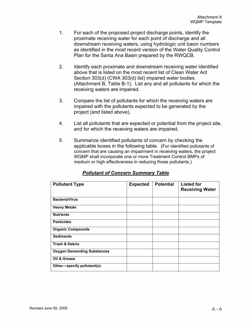
1. For each of the proposed project discharge points, identify the proximate receiving water for each point of discharge and all downstream receiving waters, using hydrologic unit basin numbers as identified in the most recent version of the Water Quality Control Plan for the Santa Ana Basin prepared by the RWQCB.
2. Identify each proximate and downstream receiving water identified
above that is listed on the most recent list of Clean Water Act Section 303(d) (CWA 303(d) list) impaired water bodies (Attachment B, Table B-1). List any and all pollutants for which the receiving waters are impaired.
3. Compare the list of pollutants for which the receiving waters are
impaired with the pollutants expected to be generated by the project (and listed above).
4. List all pollutants that are expected or potential from the project site,
and for which the receiving waters are impaired.
5. Summarize identified pollutants of concern by checking the applicable boxes in the following table. (For identified pollutants of concern that are causing an impairment in receiving waters, the project WQMP shall incorporate one or more Treatment Control BMPs of medium or high effectiveness in reducing those pollutants.)
Pollutant of Concern Summary Table
Pollutant Type
Expected Potential Listed for Receiving Water
Bacteria/Virus Heavy Metals Nutrients Pesticides Organic Compounds Sediments Trash & Debris Oxygen Demanding Substances Oil & Grease Other—specify pollutant(s):
Attachment A WQMP Template
Revised June 09, 2005 A - 7
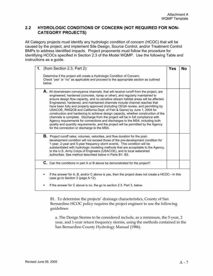
2.2 HYDROLOGIC CONDITIONS OF CONCERN (NOT REQUIRED FOR NON-CATEGORY PROJECTS)
All Category projects must identify any hydrologic condition of concern (HCOC) that will be caused by the project, and implement Site Design, Source Control, and/or Treatment Control BMPs to address identified impacts. Project proponents must follow the procedure for identifying HCOCs specified in Section 2.3 of the Model WQMP. Use the following Table and instructions as a guide.
B1. To determine the projects’ drainage characteristics, County of San Bernardino HCOC policy requires the project engineer to use the following guidelines:
a. The Design Storms to be considered include, as a minimum, the 5-year, 2 year, and 1-year return frequency storms, using the methods contained in the San Bernardino County Hydrology Manual (1986).
1. (from Section 2.3, Part 2):
Determine if the project will create a Hydrologic Condition of Concern. Check “yes” or “no” as applicable and proceed to the appropriate section as outlined below.
Yes No
A. All downstream conveyance channels, that will receive runoff from the project, are engineered, hardened (concrete, riprap or other), and regularly maintained to ensure design flow capacity, and no sensitive stream habitat areas will be affected. Engineered, hardened, and maintained channels include channel reaches that have been fully and properly approved (including CEQA review, and permitting by USACOE, RWQCB and California Dept. of Fish & Game) by June 1, 2004 for construction and hardening to achieve design capacity, whether construction of the channels is complete. Discharge from the project will be in full compliance with Agency requirements for connections and discharges to the MS4, including both quality and quantity requirements, and the project will be permitted by the Agency for the connection or discharge to the MS4.
B. Project runoff rates, volumes, velocities, and flow duration for the post-development condition will not exceed those of the pre-development condition for 1-year, 2-year and 5-year frequency storm events. This condition will be substantiated with hydrologic modeling methods that are acceptable to the Agency, to the U.S. Army Corps of Engineers (USACOE), and to local watershed authorities. See method described below in Parts B1- B3.
C. Can the conditions in part A or B above be demonstrated for the project?
If the answer for A, B, and/or C above is yes, then the project does not create a HCOC—in this
case go to Section 3 (page A-12).
If the answer for C above is no, the go to section 2.3. Part 3, below.
Attachment A WQMP Template
Revised June 09, 2005 A - 8
Project sites from 0-10 acres in size should use the Small Area Runoff Hydrograph method, found in Section J of the San Bernardino County Hydrology Manual (1986); sites greater than 10 acres should use the Unit Hydrograph Method, found in Section E of the San Bernardino County Hydrology Manual (1986). For each return frequency considered, and for both pre- and post-development conditions, determine the total runoff volume, the peak flow rate, and the time of duration, of runoff hydrograph flow rates that exceed the following flow rates: 90% of peak flow rate, 80% of peak flow rate, 70% of peak flow rate, 60% of peak flow rate, 50% of peak flow rate, 40% of peak flow rate, 30% of peak flow rate, 20% of peak flow rate, and 10% of peak flow rate (see Table B2-2, “Pre- and Post-development Hydrology Comparison Worksheet.”)
b. Sediment supply is to be estimated for pre-and post-development conditions for the land altered by the subject project using Table 2-3, “Pre- and Post-development Hydrology Comparison Worksheet” or equivalent. The Universal Soil Loss Equation published by the USDA-Natural Resources Conservation Service may be considered as an estimate of changes in sediment yield due to development, if applicable. Flow velocities are to be estimated for the several return frequency design storms noted above, as a minimum, with flow velocities estimated for each percentage of the peak flow rate value listed above. Normal depth hydraulic estimates may be used unless significant backwater effects exist such that deposition of sediment is anticipated, in which case a standard backwater analysis is to be conducted.
c. Based upon the preceding task results, the project engineer shall evaluate the Project and its impact downstream and recommend other design storm return frequencies to be considered in order to satisfy the goals and intent of the HCOC document.

Attachment A WQMP Template
Revised June 09, 2005 A - 9
Table B2-2: Pre- and Post-development Hydrology Comparison Worksheet
Total Volume Peak Flow Flow Time Duration Sediment Transport Return Period Pre Post Pre Post % of Peak Pre Post Pre Post
9080 70 60 50 40 30 20
1-year
10 9080 70 60 50 40 30 20
2-year
10 9080 70 60 50 40 30 20
5-year
10
Attachment A WQMP Template
Revised June 09, 2005 A - 10
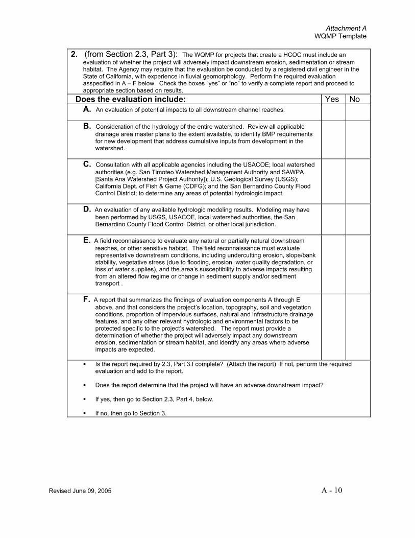
2. (from Section 2.3, Part 3): The WQMP for projects that create a HCOC must include an evaluation of whether the project will adversely impact downstream erosion, sedimentation or stream habitat. The Agency may require that the evaluation be conducted by a registered civil engineer in the State of California, with experience in fluvial geomorphology. Perform the required evaluation asspecified in A – F below. Check the boxes “yes” or “no” to verify a complete report and proceed to appropriate section based on results.
Does the evaluation include: Yes No A. An evaluation of potential impacts to all downstream channel reaches.
B. Consideration of the hydrology of the entire watershed. Review all applicable drainage area master plans to the extent available, to identify BMP requirements for new development that address cumulative inputs from development in the watershed.
C. Consultation with all applicable agencies including the USACOE; local watershed authorities (e.g. San Timoteo Watershed Management Authority and SAWPA [Santa Ana Watershed Project Authority]); U.S. Geological Survey (USGS); California Dept. of Fish & Game (CDFG); and the San Bernardino County Flood Control District; to determine any areas of potential hydrologic impact.
D. An evaluation of any available hydrologic modeling results. Modeling may have been performed by USGS, USACOE, local watershed authorities, the San Bernardino County Flood Control District, or other local jurisdiction.
E. A field reconnaissance to evaluate any natural or partially natural downstream reaches, or other sensitive habitat. The field reconnaissance must evaluate representative downstream conditions, including undercutting erosion, slope/bank stability, vegetative stress (due to flooding, erosion, water quality degradation, or loss of water supplies), and the area’s susceptibility to adverse impacts resulting from an altered flow regime or change in sediment supply and/or sediment transport .
F. A report that summarizes the findings of evaluation components A through E above, and that considers the project’s location, topography, soil and vegetation conditions, proportion of impervious surfaces, natural and infrastructure drainage features, and any other relevant hydrologic and environmental factors to be protected specific to the project’s watershed. The report must provide a determination of whether the project will adversely impact any downstream erosion, sedimentation or stream habitat, and identify any areas where adverse impacts are expected.
Is the report required by 2.3, Part 3.f complete? (Attach the report) If not, perform the required evaluation and add to the report.
Does the report determine that the project will have an adverse downstream impact?
If yes, then go to Section 2.3, Part 4, below.
If no, then go to Section 3.
Attachment A WQMP Template
Revised June 09, 2005 A - 11
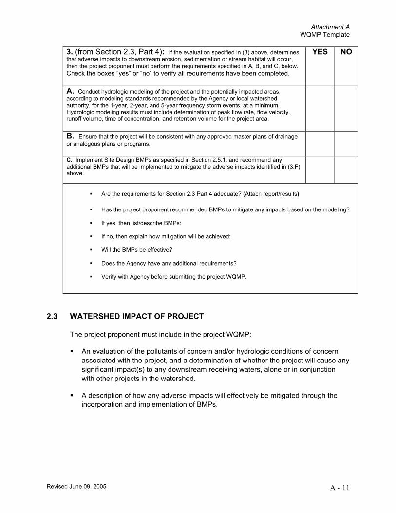
2.3 WATERSHED IMPACT OF PROJECT
The project proponent must include in the project WQMP:
An evaluation of the pollutants of concern and/or hydrologic conditions of concern associated with the project, and a determination of whether the project will cause any significant impact(s) to any downstream receiving waters, alone or in conjunction with other projects in the watershed.
A description of how any adverse impacts will effectively be mitigated through the incorporation and implementation of BMPs.
3. (from Section 2.3, Part 4): If the evaluation specified in (3) above, determines that adverse impacts to downstream erosion, sedimentation or stream habitat will occur, then the project proponent must perform the requirements specified in A, B, and C, below. Check the boxes “yes” or “no” to verify all requirements have been completed.
YES NO
A. Conduct hydrologic modeling of the project and the potentially impacted areas, according to modeling standards recommended by the Agency or local watershed authority, for the 1-year, 2-year, and 5-year frequency storm events, at a minimum. Hydrologic modeling results must include determination of peak flow rate, flow velocity, runoff volume, time of concentration, and retention volume for the project area.
B. Ensure that the project will be consistent with any approved master plans of drainage or analogous plans or programs.
C. Implement Site Design BMPs as specified in Section 2.5.1, and recommend any additional BMPs that will be implemented to mitigate the adverse impacts identified in (3.F) above.
Are the requirements for Section 2.3 Part 4 adequate? (Attach report/results)
Has the project proponent recommended BMPs to mitigate any impacts based on the modeling?
If yes, then list/describe BMPs:
If no, then explain how mitigation will be achieved:
Will the BMPs be effective?
Does the Agency have any additional requirements?
Verify with Agency before submitting the project WQMP.
Attachment A WQMP Template
Revised June 09, 2005 A - 12
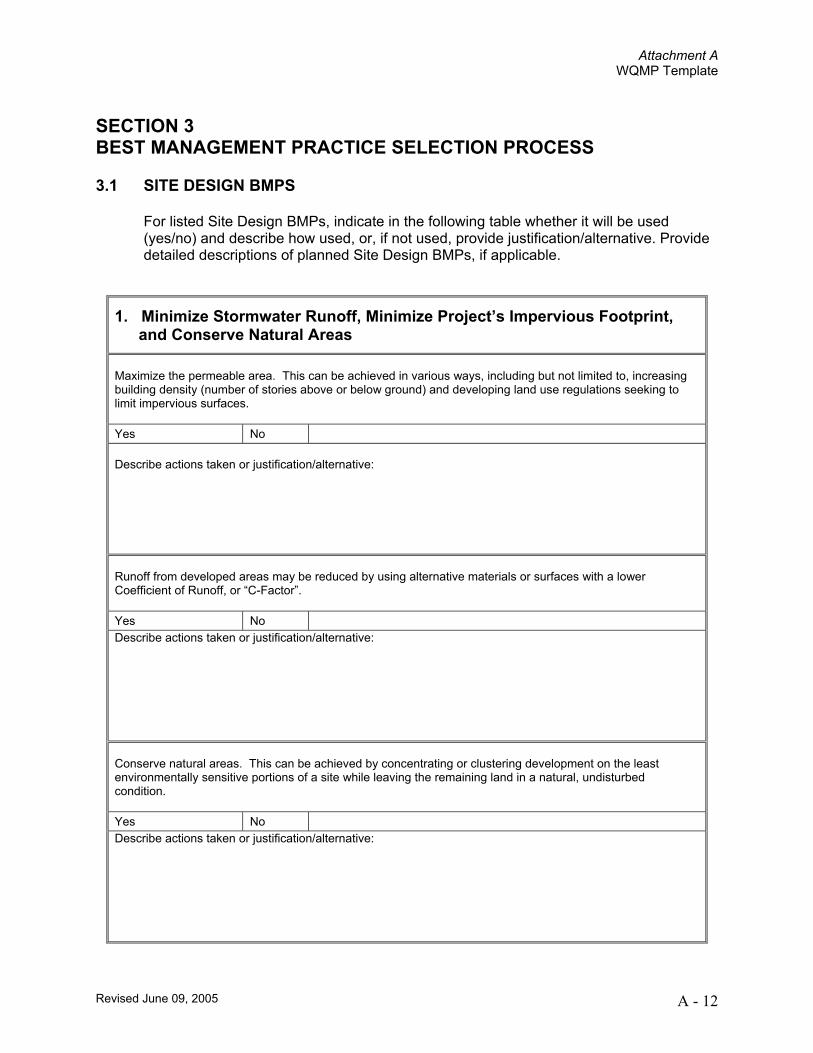
SECTION 3 BEST MANAGEMENT PRACTICE SELECTION PROCESS 3.1 SITE DESIGN BMPS
For listed Site Design BMPs, indicate in the following table whether it will be used (yes/no) and describe how used, or, if not used, provide justification/alternative. Provide detailed descriptions of planned Site Design BMPs, if applicable.
1. Minimize Stormwater Runoff, Minimize Project’s Impervious Footprint, and Conserve Natural Areas
Maximize the permeable area. This can be achieved in various ways, including but not limited to, increasing building density (number of stories above or below ground) and developing land use regulations seeking to limit impervious surfaces. Yes No Describe actions taken or justification/alternative: Runoff from developed areas may be reduced by using alternative materials or surfaces with a lower Coefficient of Runoff, or “C-Factor”. Yes No Describe actions taken or justification/alternative: Conserve natural areas. This can be achieved by concentrating or clustering development on the least environmentally sensitive portions of a site while leaving the remaining land in a natural, undisturbed condition. Yes No Describe actions taken or justification/alternative:
Attachment A WQMP Template
Revised June 09, 2005 A - 13
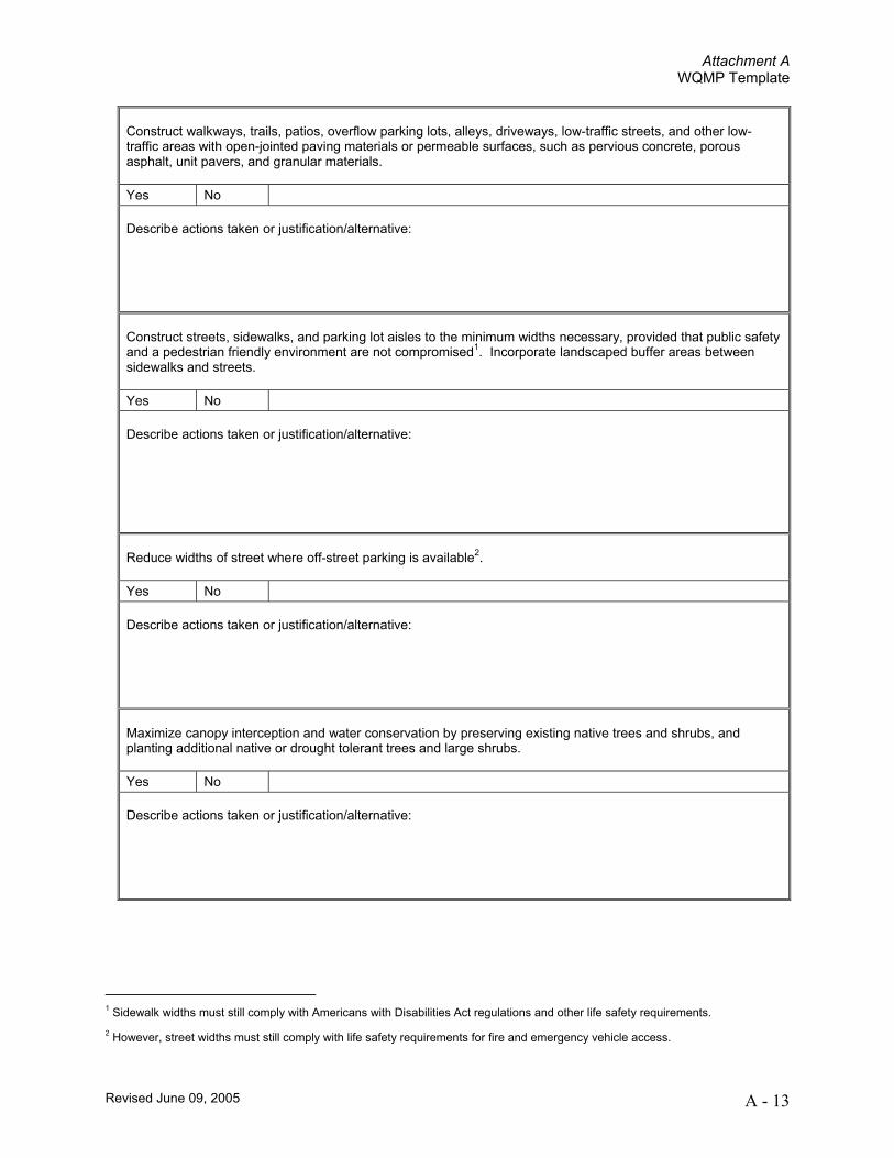
Construct walkways, trails, patios, overflow parking lots, alleys, driveways, low-traffic streets, and other low-traffic areas with open-jointed paving materials or permeable surfaces, such as pervious concrete, porous asphalt, unit pavers, and granular materials. Yes No Describe actions taken or justification/alternative: Construct streets, sidewalks, and parking lot aisles to the minimum widths necessary, provided that public safety and a pedestrian friendly environment are not compromised1. Incorporate landscaped buffer areas between sidewalks and streets. Yes No Describe actions taken or justification/alternative: Reduce widths of street where off-street parking is available2. Yes No Describe actions taken or justification/alternative: Maximize canopy interception and water conservation by preserving existing native trees and shrubs, and planting additional native or drought tolerant trees and large shrubs. Yes No Describe actions taken or justification/alternative:
1 Sidewalk widths must still comply with Americans with Disabilities Act regulations and other life safety requirements. 2 However, street widths must still comply with life safety requirements for fire and emergency vehicle access.

Attachment A WQMP Template
Revised June 09, 2005 A - 14
3However, projects must still comply with hillside grading ordinances that limit or restrict infiltration of runoff. Infiltration areas may be subject to regulation as Class V injection wells and may require a report to the USEPA. Consult the Agency for more information on use of this type of facility.
Other comparable site design options that are equally effective. Describe actions taken or justification/alternative: Minimize the use of impervious surfaces, such as decorative concrete, in the landscape design. Yes No Describe actions taken or justification/alternative: Use natural drainage systems. Yes No Describe actions taken or justification/alternative: Where soils conditions are suitable, use perforated pipe or gravel filtration pits for low flow infiltration3. Yes No Describe actions taken or justification/alternative: Construct onsite ponding areas, rain gardens, or retention facilities to increase opportunities for infiltration, while being cognizant of the need to prevent the development of vector breeding areas. Yes No Describe actions taken or justification/alternative:

Attachment A WQMP Template
Revised June 09, 2005 A - 15
2. Minimize Directly Connected Impervious Areas Where landscaping is proposed, drain rooftops into adjacent landscaping prior to discharging to the storm drain. Yes No Describe actions taken or justification/alternative: Where landscaping is proposed, drain impervious sidewalks, walkways, trails, and patios into adjacent landscaping. Yes No Describe actions taken or justification/alternative: Increase the use of vegetated drainage swales in lieu of underground piping or imperviously lined swales. Yes No Describe actions taken or justification/alternative: Use one or more of the following: Yes No Design Feature
Rural swale system: street sheet flows to vegetated swale or gravel shoulder, curbs at street corners, culverts under driveways and street crossings
Urban curb/swale system; street slopes to curb; periodic swale inlets drain to vegetated swale/biofilter.
Dual drainage system: First flush captured in street catch basins and discharged to adjacent vegetated swale or gravel shoulder, high flows connect directly to municipal storm drain systems.
Other comparable design concepts that are equally effective.
Describe actions taken or justification/alternative:

Attachment A WQMP Template
Revised June 09, 2005 A - 16
Use one or more of the following features for design of driveways and private residential parking areas:
Yes No Design Feature
Design driveways with shared access, flared (single lane at street) or wheel strips (paving only under tires); or, drain into landscaping prior to discharging to the municipal storm drain system.
Uncovered temporary or guest parking on private residential lots may be paved with a permeable surface; or designed to drain into landscaping prior to discharging to the municipal storm drain system.
Other comparable design concepts that are equally effective.
Describe actions taken or justification/alternative:
Use one or more of the following design concepts for the design of parking areas:
Yes No Design Feature
Where landscaping is proposed in parking areas, incorporate landscape areas into the drainage design.
Overflow parking (parking stalls provided in excess of the Agency’s minimum parking requirements) may be constructed with permeable paving.
Other comparable design concepts that are equally effective.
Describe actions taken or justification/alternative:

Attachment A WQMP Template
Revised June 09, 2005 A - 17
3.2 SOURCE CONTROL BMPS
Complete the following selection table for Source Control BMPs, by checking boxes that are applicable. All listed BMPs shall be implemented for the project. Where a required Source Control BMP is not applicable to the project due to project characteristics, justification and/or alternative practices for preventing pollutants must be provided. In addition to completing the following tables, provide detailed descriptions on the implementation of planned Source Control BMPs.

Attachment A WQMP Template
Revised June 09, 2005 A - 18
Source Control BMP Selection Matrix*
Source Control BMPs
Project Category E
duca
tion
of P
rope
rty O
wne
rs
Act
ivity
Res
trict
ions
Spi
ll C
ontin
genc
y P
lan
Em
ploy
ee T
rain
ing/
Edu
catio
n P
rogr
am
Stre
et S
wee
ping
Priv
ate
Stre
et
and
Par
king
Lot
s
Com
mon
Are
as C
atch
Bas
in
Insp
ectio
n
Land
scap
e P
lann
ing
(SD
-10)
Hill
side
Lan
dsca
ping
Roo
f Run
off C
ontro
ls (S
D-1
1)
Effi
cien
t Irr
igat
ion
(SD
-12)
Pro
tect
Slo
pes
and
Cha
nnel
s
Sto
rm D
rain
Sig
nage
(SD
-13)
Inle
t Tra
sh R
acks
Ene
rgy
Dis
sipa
ters
Tras
h S
tora
ge A
reas
(SD
-32)
an
d Li
tter C
ontro
l
Fuel
ing
Are
as (S
D-3
0)
Air/
Wat
er S
uppl
y A
rea
Dra
inag
e
Mai
nten
ance
Bay
s an
d D
ocks
(S
D-3
1)
Veh
icle
Was
hing
Are
as (S
D-
33)
Out
door
Mat
eria
l Sto
rage
A
reas
(SD
-34)
Out
door
Wor
k A
reas
(SD
-35)
Out
door
Pro
cess
ing
Are
as
(SD
-36)
Was
h W
ater
Con
trols
for F
ood
Pre
para
tion
Are
as
Per
viou
s P
avem
ent (
SD
-20)
Alte
rnat
ive
Bui
ldin
g M
ater
ials
(S
D-2
1)
Significant Re-development
Home subdivisions of 10 or more units
Commercial/ Industrial
Development >100,000 ft2
Automotive Repair Shop
Restaurants
Hillside Development
>10,000 ft2
Development of impervious
surface >2,500 ft2
Parking Lots >5,000 ft2 of
exposed storm water
* Provide justification of each Source Control BMP that will not be incorporated in the project WQMP, or explanation of proposed equally effective alternatives in the following table.
Attachment A WQMP Template
Revised June 09, 2005 A - 19
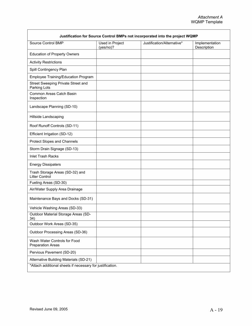
Justification for Source Control BMPs not incorporated into the project WQMP
Source Control BMP Used in Project (yes/no)?
Justification/Alternative* Implementation Description
Education of Property Owners
Activity Restrictions
Spill Contingency Plan
Employee Training/Education Program
Street Sweeping Private Street and Parking Lots
Common Areas Catch Basin Inspection
Landscape Planning (SD-10)
Hillside Landscaping
Roof Runoff Controls (SD-11)
Efficient Irrigation (SD-12)
Protect Slopes and Channels
Storm Drain Signage (SD-13)
Inlet Trash Racks
Energy Dissipaters
Trash Storage Areas (SD-32) and Litter Control
Fueling Areas (SD-30)
Air/Water Supply Area Drainage
Maintenance Bays and Docks (SD-31)
Vehicle Washing Areas (SD-33)
Outdoor Material Storage Areas (SD-34)
Outdoor Work Areas (SD-35)
Outdoor Processing Areas (SD-36)
Wash Water Controls for Food Preparation Areas
Pervious Pavement (SD-20)
Alternative Building Materials (SD-21)
*Attach additional sheets if necessary for justification.
Attachment A WQMP Template
Revised June 09, 2005 A - 20
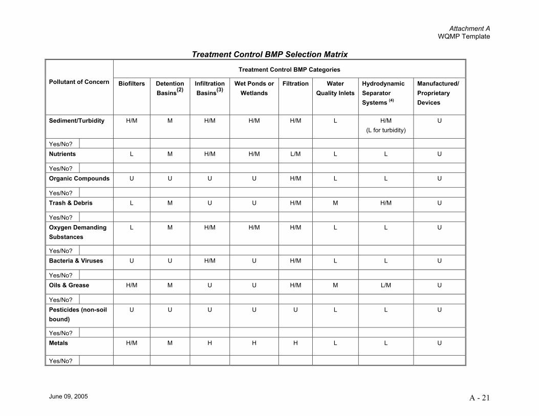
3.3 TREATMENT CONTROL BMPS (Not required for Non-Category projects)
Complete the following Treatment Control BMPs Selection Matrix. For each pollutant of concern enter “yes” if identified in Section 2.1, above, or “no” if not identified for the project. Check the boxes of selected BMPs that will be implemented for the project to address each pollutant of concern from the project as listed above in section 2.1. Treatment Control BMPs must be selected and installed with respect to identified pollutant characteristics and concentrations that will be discharged from the site. For any identified pollutants of concern not listed in the Treatment Control BMP Selection Matrix, provide an explanation of how they will be addressed by Treatment Control BMPs. For identified pollutants of concern that are causing an impairment in receiving waters (as identified in Section 2.1, above), the project WQMP shall incorporate one or more Treatment Control BMPs of medium or high effectiveness in reducing those pollutants. It is the responsibility of the project proponent to demonstrate, and document in the project WQMP, that all pollutants of concern will be fully addressed. The Agency may require information beyond the minimum requirements of this WQMP to demonstrate that adequate pollutant treatment is being accomplished.
In addition to completing the Selection Matrix, provide detailed descriptions on the
location, implementation, installation, and long-term O&M of planned Treatment Control BMPs.
Attachment A WQMP Template
June 09, 2005 A - 21
Treatment Control BMP Selection Matrix
Treatment Control BMP Categories
Pollutant of Concern Biofilters Detention Basins(2)
Infiltration Basins(3)
Wet Ponds or Wetlands
Filtration Water Quality Inlets
Hydrodynamic Separator Systems (4)
Manufactured/ Proprietary Devices
Sediment/Turbidity H/M M H/M H/M H/M L H/M (L for turbidity)
U
Yes/No? Nutrients L M H/M H/M L/M L L U
Yes/No? Organic Compounds U U U U H/M L L U
Yes/No? Trash & Debris L M U U H/M M H/M U
Yes/No? Oxygen Demanding Substances
L M H/M H/M H/M L L U
Yes/No? Bacteria & Viruses U U H/M U H/M L L U
Yes/No? Oils & Grease H/M M U U H/M M L/M U
Yes/No? Pesticides (non-soil bound)
U U U U U L L U
Yes/No? Metals H/M M H H H L L U
Yes/No?
Attachment A WQMP Template
June 09, 2005 A - 22
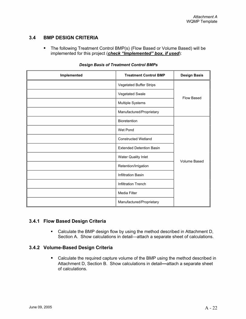
3.4 BMP DESIGN CRITERIA
The following Treatment Control BMP(s) (Flow Based or Volume Based) will be
implemented for this project (check “Implemented” box, if used):
3.4.1 Flow Based Design Criteria
Calculate the BMP design flow by using the method described in Attachment D, Section A. Show calculations in detail—attach a separate sheet of calculations.
3.4.2 Volume-Based Design Criteria
Calculate the required capture volume of the BMP using the method described in Attachment D, Section B. Show calculations in detail—attach a separate sheet of calculations.
Design Basis of Treatment Control BMPs
Implemented Treatment Control BMP Design Basis
Vegetated Buffer Strips
Vegetated Swale
Multiple Systems
Manufactured/Proprietary
Flow Based
Bioretention
Wet Pond
Constructed Wetland
Extended Detention Basin
Water Quality Inlet
Retention/Irrigation
Infiltration Basin
Infiltration Trench
Media Filter
Manufactured/Proprietary
Volume Based
Attachment A WQMP Template
June 09, 2005 A - 23
Section 4 Operation and Maintenance 4.1 Operations and Maintenance
Operation and maintenance (O&M) requirements for all Source Control, Site Design, and Treatment Control BMPs shall be identified within the WQMP. The WQMP shall include the following:
4.1.1 O&M DESCRIPTION AND SCHEDULE THAT MUST:
List and identify each BMP that requires O&M.
Provide a thorough description of O&M activities (include the O&M
process, and the handling and placement of any wastes). Include BMP start-up dates.
Provide a schedule of the frequency of O&M for each BMP.
4.1.2 INSPECTION & MONITORING REQUIREMENTS THAT MUST:
Provide thorough descriptions of water quality monitoring (if locally required).
Provide self-inspections and record keeping requirements for BMPs (review
local specific requirements regarding self-inspections and/or annual reporting), including identification of responsible parties for inspection and record keeping.
4.1.3 IDENTIFICATION OF RESPONSIBLE PARTIES THAT MUST:
Provide the party or parties that will be responsible for each BMP O&M. For
each responsible party, include the party’s name, address, contact name and telephone number.
SECTION 5 FUNDING 5.1 Funding
The Permit requires that for all Treatment Control BMPs, a funding source or sources for operation and maintenance of each BMP be identified within the WQMP. Project proponents must:
Indicate funding sources or sources for O&M for this project. For each funding source, include the responsible party’s name, address, contact name and telephone number.
Attachment A WQMP Template
June 09, 2005 A - 24
SECTION 6 WQMP Certification 6.1 Certification
The applicant is required to sign and certify that the WQMP is in conformance with Santa
Ana Regional Water Quality Control Board Order Number R8-2002-0012 (NPDES Permit No. CAS618036).
The applicant is required to sign and date the following statement ‘word-for-word’ certifying that the provisions of the WQMP have been accepted by the applicant and that the applicant will have the plan transferred to future successors (transferability statement). The certification must be signed by the property owner, unless a written designation by the owner allows a designee to sign on the owner’s behalf.
“This Water Quality Management Plan has been prepared for (Owner/Developer Name) by (Consulting /Engineering Firm Name). It is intended to comply with the requirements of the City of (name city or county) for Tract/Parcel Map No. ______, Condition Number(s) _____________ requiring the preparation of a Water Quality Management Plan (WQMP). The undersigned is aware that Best Management Practices (BMPs) are enforceable pursuant to the City’s/County’s Water Quality Ordinance No. _______. The undersigned, while it owns the subject property, is responsible for the implementation of the provisions of this plan and will ensure that this plan is amended as appropriate to reflect up-to-date conditions on the site consistent with San Bernardino County’s Municipal Stormwater Management Program and the intent of the NPDES Permit for San Bernardino County and the incorporated cities of San Bernardino County within the Santa Ana Region. Once the undersigned transfers its interest in the property, its successors in interest and the city/county shall be notified of the transfer. The new owner will be informed of its responsibility under this WQMP. A copy of the approved WQMP shall be available on the subject site in perpetuity. “ “I certify under a penalty of law that the provisions (implementation, operation, maintenance, and funding) of the WQMP have been accepted and that the plan will be transferred to future successors.” _____________________________ _____________________________
Applicant’s Signature Date _____________________________ ____________________________
Applicant’s Name Applicant’s Telephone Number
Attachment A WQMP Template
June 09, 2005 A - 25
Attachment A-1 Maintenance Mechanisms
A-1.1 The Agency shall not accept stormwater structural BMPs as meeting the WQMP requirements standard, unless an O&M Plan is prepared (see WQMP Section 2.6) and a mechanism is in place that will ensure ongoing long-term maintenance of all structural and non-structural BMPs. This mechanism can be provided by the Agency or by the project proponent. As part of project review, if a project proponent is required to include interim or permanent structural and non-structural BMPs in project plans, and if the Agency does not provide a mechanism for BMP maintenance, the Agency shall require that the applicant provide verification of maintenance requirements through such means as may be appropriate, at the discretion of the Agency, including, but not limited to covenants, legal agreements, maintenance agreements, conditional use permits and/or funding arrangements (OC 2003)
A-1.2 Maintenance Mechanisms
1. Public entity maintenance: The Agency may approve a public or acceptable quasi-public entity (e.g., the County Flood Control District, or annex to an existing assessment district, an existing utility district, a state or federal resource agency, or a conservation conservancy) to assume responsibility for operation, maintenance, repair and replacement of the BMP. Unless otherwise acceptable to individual Agencies, public entity maintenance agreements shall ensure estimated costs are front-funded or reliably guaranteed, (e.g., through a trust fund, assessment district fees, bond, letter of credit or similar means). In addition, the Permittees may seek protection from liability by appropriate releases and indemnities.
The Agency shall have the authority to approve stormwater BMPs proposed for transfer to any other public entity within its jurisdiction before installation. The Permittee shall be involved in the negotiation of maintenance requirements with any other public entities accepting maintenance responsibilities within their respective jurisdictions; and in negotiations with the resource agencies responsible for issuing permits for the construction and/or maintenance of the facilities. The Agency must be identified as a third party beneficiary empowered to enforce any such maintenance agreement within their respective jurisdictions.
2. Project proponent agreement to maintain stormwater BMPs: The Agency may
enter into a contract with the project proponent obliging the project proponent to maintain, repair and replace the stormwater BMP as necessary into perpetuity. Security or a funding mechanism with a “no sunset” clause may be required.
3. Assessment districts: The Agency may approve an Assessment District or other
funding mechanism created by the project proponent to provide funds for stormwater
Attachment A WQMP Template
June 09, 2005 A - 26
BMP maintenance, repair and replacement on an ongoing basis. Any agreement with such a District shall be subject to the Public Entity Maintenance Provisions above.
4. Lease provisions: In those cases where the Agency holds title to the land in
question, and the land is being leased to another party for private or public use, the Agency may assure stormwater BMP maintenance, repair and replacement through conditions in the lease.
5. Conditional use permits: For discretionary projects only, the Agency may assure
maintenance of stormwater BMPs through the inclusion of maintenance conditions in the conditional use permit. Security may be required.
6. Alternative mechanisms: The Agency may accept alternative maintenance
mechanisms if such mechanisms are as protective as those listed above.
Attachment A WQMP Template
June 09, 2005 A - 27
Attachment A-2 Water Quality Management Plan and Stormwater BMP Transfer, Access and Maintenance Agreement (adapted from documents from the Ventura County Stormwater Management Program)
Recorded at the request of: City of ________________________________________________________ After recording, return to: City of ________________________________________________________ City Clerk _____________________________________________________
Water Quality Management Plan and Stormwater BMP Transfer, Access and Maintenance Agreement
OWNER: ____________________________________________________ PROPERTY ADDRESS: ________________________________________
________________________________________
APN: ________________________________________________________ THIS AGREEMENT is made and entered into in ___________________________, California, this _______ day of __________________ , by and between _______________________________________________, herein after
Attachment A WQMP Template
June 09, 2005 A - 28
referred to as “Owner” and the CITY OF _____________________________, a municipal corporation, located in the County of San Bernardino, State of California hereinafter referred to as “CITY”; WHEREAS, the Owner owns real property (“Property”) in the City of ________________________, County of San Bernardino, State of California, more specifically described in Exhibit “A” and depicted in Exhibit “B”, each of which exhibits is attached hereto and incorporated herein by this reference; WHEREAS, at the time of initial approval of development project known as ________________________________________ within the Property described herein, the City required the project to employ Best Management Practices, hereinafter referred to as “BMPs,” to minimize pollutants in urban runoff; WHEREAS, the Owner has chosen to install and/or implement BMPs as described in the Water Quality Management Plan, on file with the City, hereinafter referred to as “WQMP”, to minimize pollutants in urban runoff and to minimize other adverse impacts of urban runoff; WHEREAS, said WQMP has been certified by the Owner and reviewed and approved by the City; WHEREAS, said BMPs, with installation and/or implementation on private property and draining only private property, are part of a private facility with all maintenance or replacement, therefore, the sole responsibility of the Owner in accordance with the terms of this Agreement; WHEREAS, the Owner is aware that periodic and continuous maintenance, including, but not necessarily limited to, filter material replacement and sediment removal, is required to assure peak performance of all BMPs in the WQMP and that, furthermore, such maintenance activity will require compliance with all Local, State, or Federal laws and regulations, including those pertaining to confined space and waste disposal methods, in effect at the time such maintenance occurs; NOW THEREFORE, it is mutually stipulated and agreed as follows: 1. Owner hereby provides the City of City’s designee complete access, of any
duration, to the BMPs and their immediate vicinity at any time, upon reasonable notice, or in the event of emergency, as determined by City’s Director of Public Works no advance notice, for the purpose of inspection, sampling, testing of the Device, and in case of emergency, to undertake all necessary repairs or other preventative measures at owner’s expense as provided in paragraph 3 below. City shall make every effort at all times to minimize or avoid interference with Owner’s use of the Property.
Attachment A WQMP Template
June 09, 2005 A - 29
2. Owner shall use its best efforts diligently to maintain all BMPs in a manner
assuring peak performance at all times. All reasonable precautions shall be exercised by Owner and Owner’s representative or contractor in the removal and extraction of any material(s) from the BMPs and the ultimate disposal of the material(s) in a manner consistent with all relevant laws and regulations in effect at the time. As may be requested from time to time by the City, the Owner shall provide the City with documentation identifying the material(s) removed, the quantity, and disposal destination.
3. In the event Owner, or its successors or assigns, fails to accomplish the necessary
maintenance contemplated by this Agreement, within five (5) days of being given written notice by the City, the City is hereby authorized to cause any maintenance necessary to be done and charge the entire cost and expense to the Owner or Owner’s successors or assigns, including administrative costs, attorneys fees and interest thereon at the maximum rate authorized by the Civil Code from the date of the notice of expense until paid in full.
4. The City may require the owner to post security in form and for a time period
satisfactory to the city to guarantee the performance of the obligations state herein. Should the Owner fail to perform the obligations under the Agreement, the City may, in the case of a cash bond, act for the Owner using the proceeds from it, or in the case of a surety bond, require the sureties to perform the obligations of the Agreement. As an additional remedy, the Director may withdraw any previous stormwater-related approval with respect to the property on which BMPs have been installed and/or implemented until such time as Owner repays to City its reasonable costs incurred in accordance with paragraph 3 above.
5. This agreement shall be recorded in the Office of the Recorder of San Bernardino
County, California, at the expense of the Owner and shall constitute notice to all successors and assigns of the title to said Property of the obligation herein set forth, and also a lien in such amount as will fully reimburse the City, including interest as herein above set forth, subject to foreclosure in event of default in payment.
6. In event of legal action occasioned by any default or action of the Owner, or its
successors or assigns, then the Owner and its successors or assigns agree(s) to pay all costs incurred by the City in enforcing the terms of this Agreement, including reasonable attorney’s fees and costs, and that the same shall become a part of the lien against said Property.
7. It is the intent of the parties hereto that burdens and benefits herein undertaken
shall constitute covenants that run with said Property and constitute a lien there against.
Attachment A WQMP Template
June 09, 2005 A - 30
8. The obligations herein undertaken shall be binding upon the heirs, successors, executors, administrators and assigns of the parties hereto. The term “Owner” shall include not only the present Owner, but also its heirs, successors, executors, administrators, and assigns. Owner shall notify any successor to title of all or part of the Property about the existence of this Agreement. Owner shall provide such notice prior to such successor obtaining an interest in all or part of the Property. Owner shall provide a copy of such notice to the City at the same time such notice is provided to the successor.
9. Time is of the essence in the performance of this Agreement. 10. Any notice to a party required or called for in this Agreement shall be served in
person, or by deposit in the U.S. Mail, first class postage prepaid, to the address set forth below. Notice(s) shall be deemed effective upon receipt, or seventy-two (72) hours after deposit in the U.S. Mail, whichever is earlier. A party may change a notice address only by providing written notice thereof to the other party.
Attachment A WQMP Template
June 09, 2005 A - 31
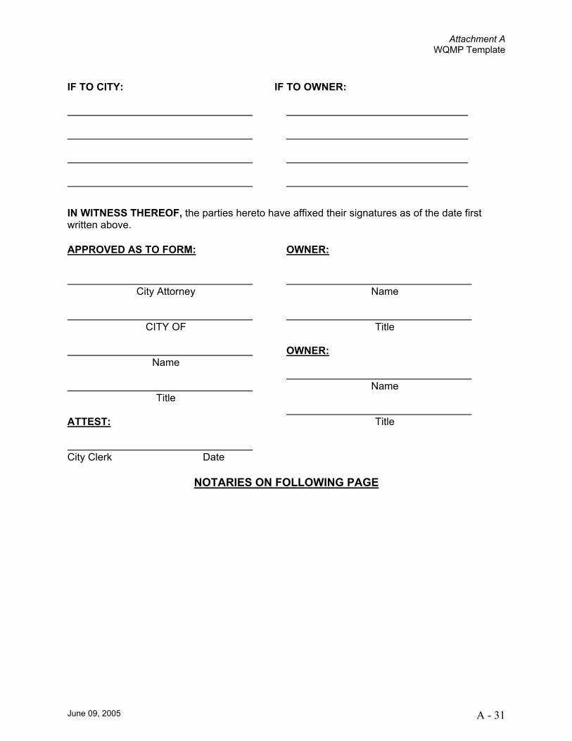
IF TO CITY:
IF TO OWNER:
IN WITNESS THEREOF, the parties hereto have affixed their signatures as of the date first written above. APPROVED AS TO FORM: OWNER:
City Attorney
CITY OF
Name
Title ATTEST: City Clerk Date
Name
Title
OWNER:
Name
Title
NOTARIES ON FOLLOWING PAGE

Attachment A WQMP Template
June 09, 2005 A - 32
EXHIBIT A
(Legal Description)

Attachment A WQMP Template
June 09, 2005 A - 33
EXHIBIT B (Map/llustration)

Attachment B Tables
Attachment B Tables
June 09, 2005 B - 1
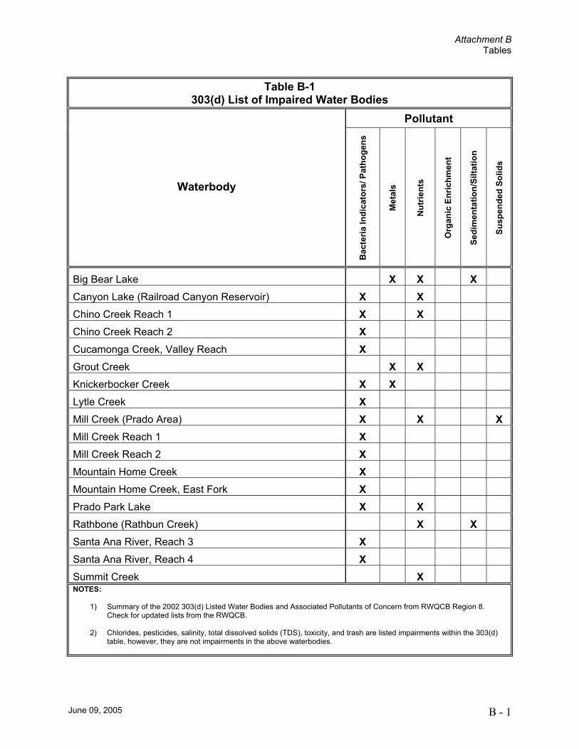
Table B-1 303(d) List of Impaired Water Bodies
Pollutant
Waterbody
Bac
teria
Indi
cato
rs/ P
atho
gens
Met
als
Nut
rient
s
Org
anic
Enr
ichm
ent
Sedi
men
tatio
n/Si
ltatio
n
Susp
ende
d So
lids
Big Bear Lake X X X Canyon Lake (Railroad Canyon Reservoir) X X Chino Creek Reach 1 X X Chino Creek Reach 2 X Cucamonga Creek, Valley Reach X Grout Creek X X Knickerbocker Creek X X Lytle Creek X Mill Creek (Prado Area) X X X Mill Creek Reach 1 X Mill Creek Reach 2 X Mountain Home Creek X Mountain Home Creek, East Fork X Prado Park Lake X X Rathbone (Rathbun Creek) X X Santa Ana River, Reach 3 X Santa Ana River, Reach 4 X Summit Creek X NOTES:
1) Summary of the 2002 303(d) Listed Water Bodies and Associated Pollutants of Concern from RWQCB Region 8. Check for updated lists from the RWQCB.
2) Chlorides, pesticides, salinity, total dissolved solids (TDS), toxicity, and trash are listed impairments within the 303(d)
table, however, they are not impairments in the above waterbodies.
Attachment B Tables
June 09, 2005 B - 2
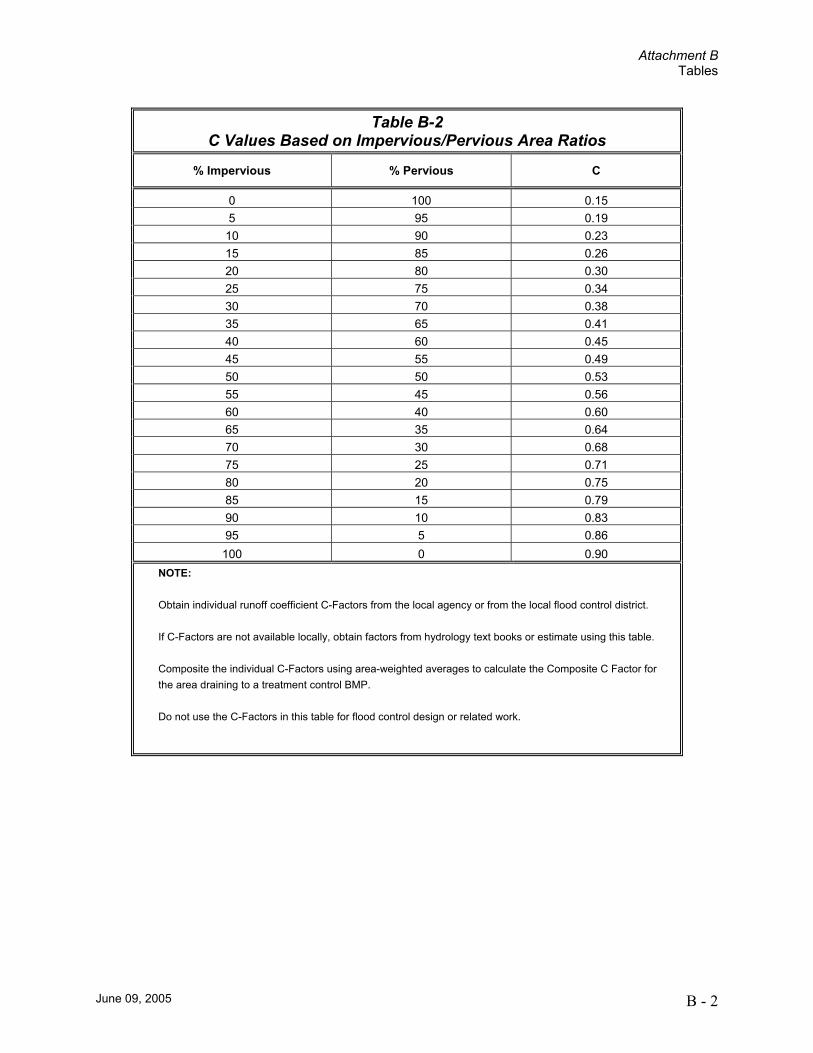
Table B-2 C Values Based on Impervious/Pervious Area Ratios
% Impervious % Pervious C
0 100 0.15 5 95 0.19
10 90 0.23 15 85 0.26 20 80 0.30 25 75 0.34 30 70 0.38 35 65 0.41 40 60 0.45 45 55 0.49 50 50 0.53 55 45 0.56 60 40 0.60 65 35 0.64 70 30 0.68 75 25 0.71 80 20 0.75 85 15 0.79 90 10 0.83 95 5 0.86 100 0 0.90
NOTE:
Obtain individual runoff coefficient C-Factors from the local agency or from the local flood control district.
If C-Factors are not available locally, obtain factors from hydrology text books or estimate using this table.
Composite the individual C-Factors using area-weighted averages to calculate the Composite C Factor for the area draining to a treatment control BMP.
Do not use the C-Factors in this table for flood control design or related work.

Attachment C Pollutants of Concern
Attachment C Pollutants of Concern
June 09, 2005 C - 1
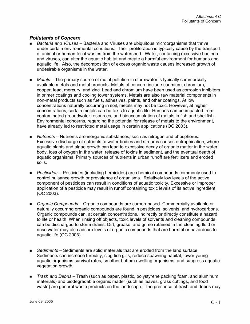
Pollutants of Concern Bacteria and Viruses – Bacteria and Viruses are ubiquitous microorganisms that thrive
under certain environmental conditions. Their proliferation is typically cause by the transport of animal or human fecal wastes from the watershed. Water, containing excessive bacteria and viruses, can alter the aquatic habitat and create a harmful environment for humans and aquatic life. Also, the decomposition of excess organic waste causes increased growth of undesirable organisms in the water.
Metals – The primary source of metal pollution in stormwater is typically commercially
available metals and metal products. Metals of concern include cadmium, chromium, copper, lead, mercury, and zinc. Lead and chromium have been used as corrosion inhibitors in primer coatings and cooling tower systems. Metals are also raw material components in non-metal products such as fuels, adhesives, paints, and other coatings. At low concentrations naturally occurring in soil, metals may not be toxic. However, at higher concentrations, certain metals can be toxic to aquatic life. Humans can be impacted from contaminated groundwater resources, and bioaccumulation of metals in fish and shellfish. Environmental concerns, regarding the potential for release of metals to the environment, have already led to restricted metal usage in certain applications (OC 2003).
Nutrients – Nutrients are inorganic substances, such as nitrogen and phosphorus.
Excessive discharge of nutrients to water bodies and streams causes eutrophication, where aquatic plants and algae growth can lead to excessive decay of organic matter in the water body, loss of oxygen in the water, release of toxins in sediment, and the eventual death of aquatic organisms. Primary sources of nutrients in urban runoff are fertilizers and eroded soils.
Pesticides -- Pesticides (including herbicides) are chemical compounds commonly used to
control nuisance growth or prevalence of organisms. Relatively low levels of the active component of pesticides can result in conditions of aquatic toxicity. Excessive or improper application of a pesticide may result in runoff containing toxic levels of its active ingredient (OC 2003).
Organic Compounds – Organic compounds are carbon-based. Commercially available or
naturally occurring organic compounds are found in pesticides, solvents, and hydrocarbons. Organic compounds can, at certain concentrations, indirectly or directly constitute a hazard to life or health. When rinsing off objects, toxic levels of solvents and cleaning compounds can be discharged to storm drains. Dirt, grease, and grime retained in the cleaning fluid or rinse water may also adsorb levels of organic compounds that are harmful or hazardous to aquatic life (OC 2003).
Sediments – Sediments are solid materials that are eroded from the land surface.
Sediments can increase turbidity, clog fish gills, reduce spawning habitat, lower young aquatic organisms survival rates, smother bottom dwelling organisms, and suppress aquatic vegetation growth.
Trash and Debris – Trash (such as paper, plastic, polystyrene packing foam, and aluminum
materials) and biodegradable organic matter (such as leaves, grass cuttings, and food waste) are general waste products on the landscape. The presence of trash and debris may

Attachment C Pollutants of Concern
June 09, 2005 C - 2
have a significant impact on the recreational value of a water body and aquatic habitat. Trash impacts water quality by increasing biochemical oxygen demand.
Oxygen-Demanding Substances – This category includes biodegradable organic material
as well as chemicals that react with dissolved oxygen in water to form other compounds. Proteins, carbohydrates, and fats are examples of biodegradable organic compounds. Compounds such as ammonia and hydrogen sulfide are examples of oxygen-demanding compounds. The oxygen demand of a substance can lead to depletion of dissolved oxygen in a water body and possibly the development of septic conditions. A reduction of dissolved oxygen is detrimental to aquatic life and can generate hazardous compounds such as hydrogen sulfides.
Oil and Grease – Oil and grease in water bodies decreases the aesthetic value of the water
body, as well as the water quality. Primary sources of oil and grease are petroleum hydrocarbon products, motor products from leaking vehicles, esters, oils, fats, waxes, and high molecular-weight fatty acids.

Attachment D Treatment Control BMP Sizing Calculations
June 09, 2005 D - 1
Attachment D Flow- and Volume-Based BMP Design
Calculations
Attachment D Treatment Control BMP Sizing Calculations
June 09, 2005 D - 2
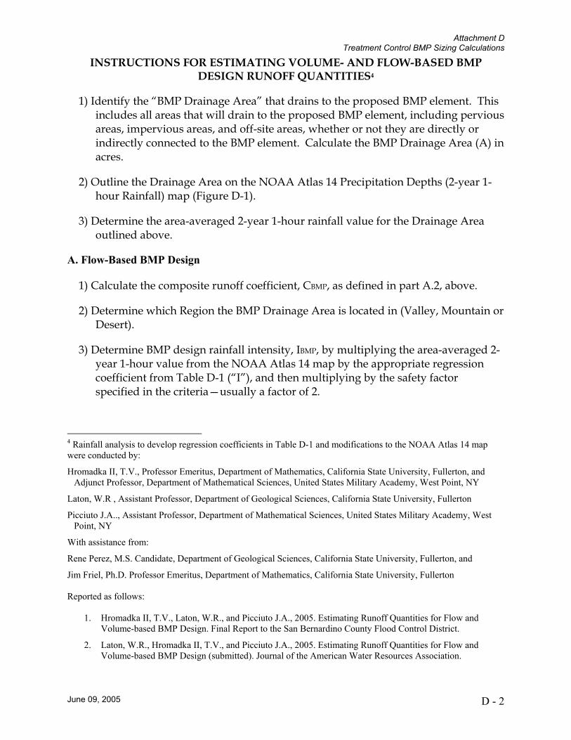
INSTRUCTIONS FOR ESTIMATING VOLUME- AND FLOW-BASED BMP DESIGN RUNOFF QUANTITIES4
1) Identify the “BMP Drainage Area” that drains to the proposed BMP element. This includes all areas that will drain to the proposed BMP element, including pervious areas, impervious areas, and off-site areas, whether or not they are directly or indirectly connected to the BMP element. Calculate the BMP Drainage Area (A) in acres.
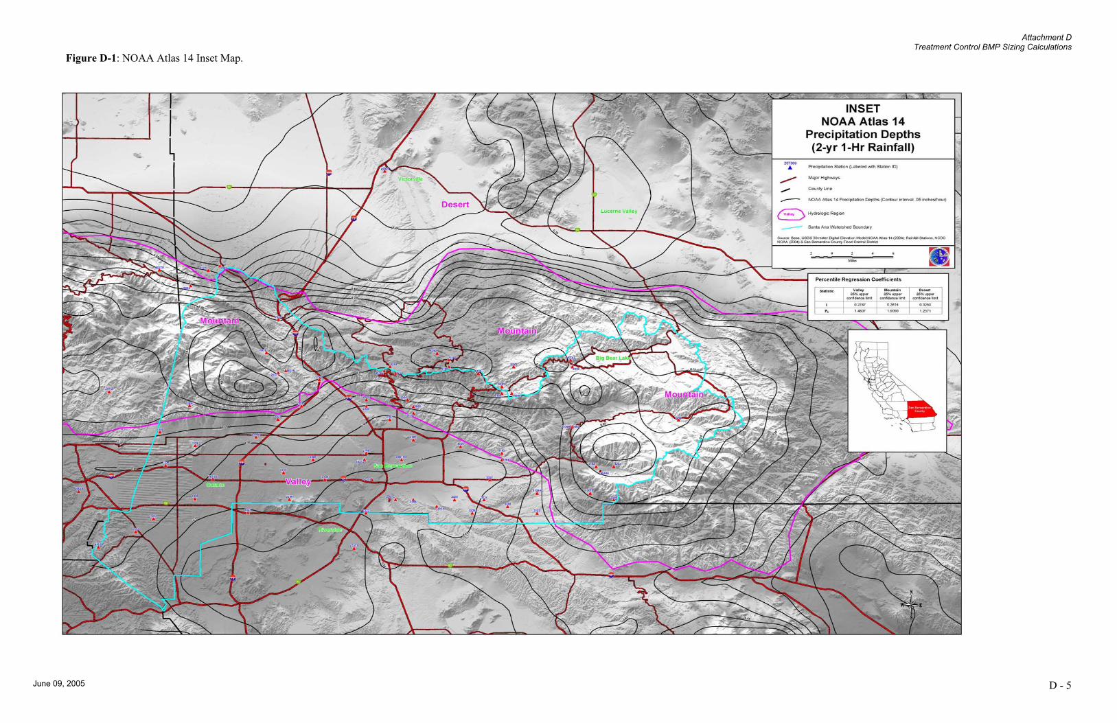
2) Outline the Drainage Area on the NOAA Atlas 14 Precipitation Depths (2-year 1-hour Rainfall) map (Figure D-1).
3) Determine the area-averaged 2-year 1-hour rainfall value for the Drainage Area outlined above.
A. Flow-Based BMP Design
1) Calculate the composite runoff coefficient, CBMP, as defined in part A.2, above.
2) Determine which Region the BMP Drainage Area is located in (Valley, Mountain or Desert).
3) Determine BMP design rainfall intensity, IBMP, by multiplying the area-averaged 2-year 1-hour value from the NOAA Atlas 14 map by the appropriate regression coefficient from Table D-1 (“I”), and then multiplying by the safety factor specified in the criteria—usually a factor of 2.
4 Rainfall analysis to develop regression coefficients in Table D-1 and modifications to the NOAA Atlas 14 map were conducted by:
Hromadka II, T.V., Professor Emeritus, Department of Mathematics, California State University, Fullerton, and Adjunct Professor, Department of Mathematical Sciences, United States Military Academy, West Point, NY
Laton, W.R , Assistant Professor, Department of Geological Sciences, California State University, Fullerton
Picciuto J.A.., Assistant Professor, Department of Mathematical Sciences, United States Military Academy, West Point, NY
With assistance from:
Rene Perez, M.S. Candidate, Department of Geological Sciences, California State University, Fullerton, and
Jim Friel, Ph.D. Professor Emeritus, Department of Mathematics, California State University, Fullerton Reported as follows:
1. Hromadka II, T.V., Laton, W.R., and Picciuto J.A., 2005. Estimating Runoff Quantities for Flow and Volume-based BMP Design. Final Report to the San Bernardino County Flood Control District.
2. Laton, W.R., Hromadka II, T.V., and Picciuto J.A., 2005. Estimating Runoff Quantities for Flow and Volume-based BMP Design (submitted). Journal of the American Water Resources Association.
Attachment D Treatment Control BMP Sizing Calculations
June 09, 2005 D - 3
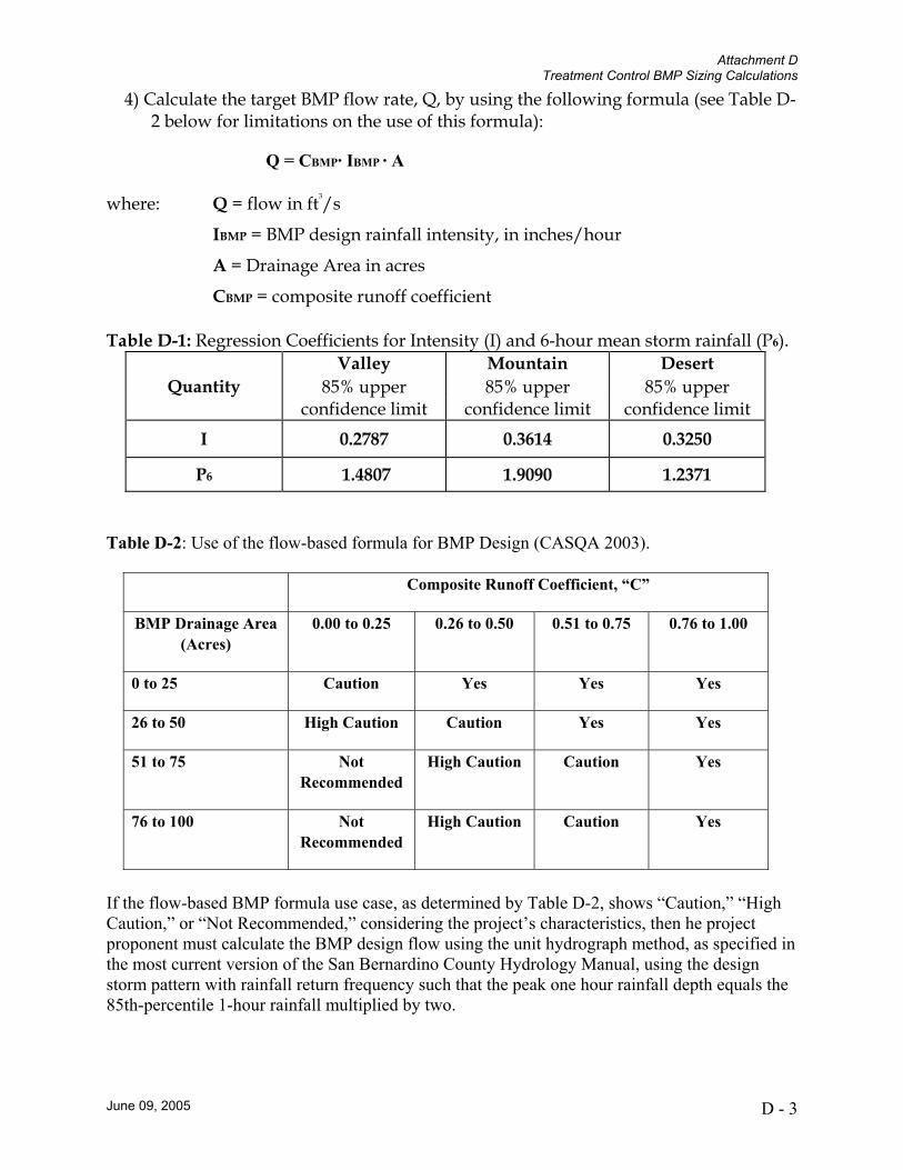
4) Calculate the target BMP flow rate, Q, by using the following formula (see Table D-2 below for limitations on the use of this formula):
Q = CBMP· IBMP · A
where: Q = flow in ft3/s
IBMP = BMP design rainfall intensity, in inches/hour
A = Drainage Area in acres
CBMP = composite runoff coefficient Table D-1: Regression Coefficients for Intensity (I) and 6-hour mean storm rainfall (P6).
Valley Mountain Desert Quantity 85% upper 85% upper 85% upper
confidence limit confidence limit confidence limit
I 0.2787 0.3614 0.3250
P6 1.4807 1.9090 1.2371
Table D-2: Use of the flow-based formula for BMP Design (CASQA 2003).
Composite Runoff Coefficient, “C”
BMP Drainage Area (Acres)
0.00 to 0.25 0.26 to 0.50 0.51 to 0.75 0.76 to 1.00
0 to 25 Caution Yes Yes Yes
26 to 50 High Caution Caution Yes Yes
51 to 75 Not Recommended
High Caution Caution Yes
76 to 100 Not Recommended
High Caution Caution Yes
If the flow-based BMP formula use case, as determined by Table D-2, shows “Caution,” “High Caution,” or “Not Recommended,” considering the project’s characteristics, then he project proponent must calculate the BMP design flow using the unit hydrograph method, as specified in the most current version of the San Bernardino County Hydrology Manual, using the design storm pattern with rainfall return frequency such that the peak one hour rainfall depth equals the 85th-percentile 1-hour rainfall multiplied by two.
Attachment D Treatment Control BMP Sizing Calculations
June 09, 2005 D - 4
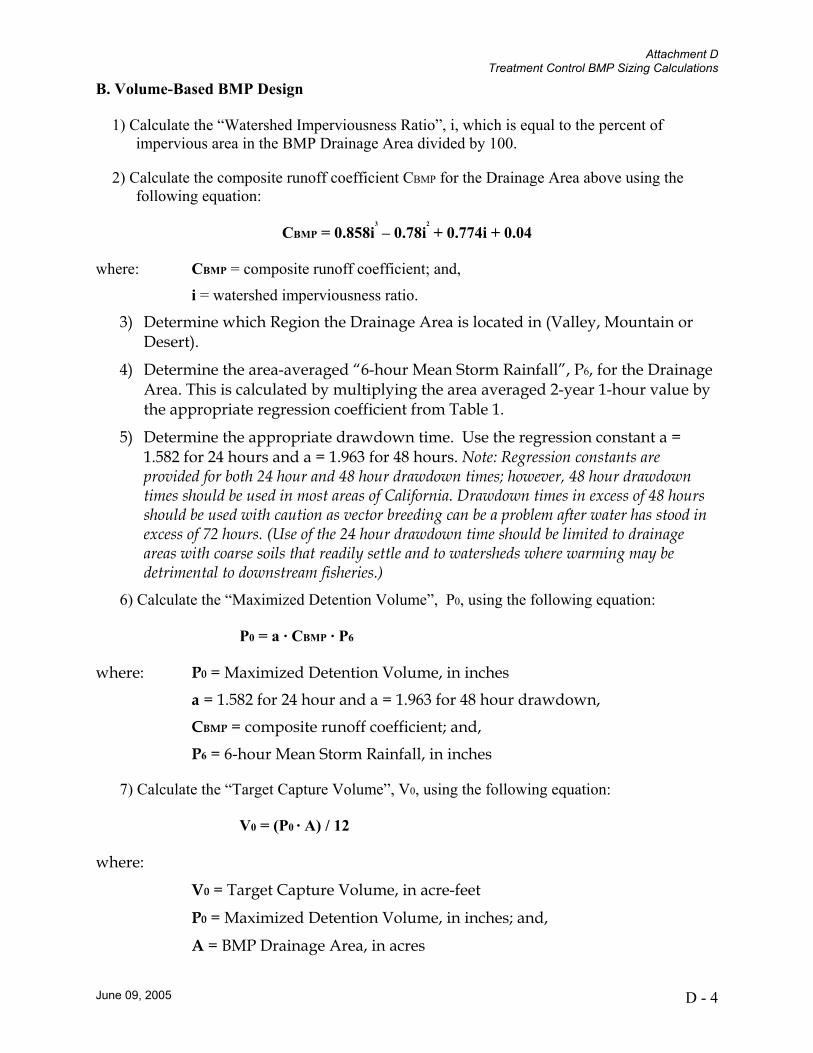
B. Volume-Based BMP Design
1) Calculate the “Watershed Imperviousness Ratio”, i, which is equal to the percent of impervious area in the BMP Drainage Area divided by 100.
2) Calculate the composite runoff coefficient CBMP for the Drainage Area above using the following equation:
CBMP = 0.858i3
– 0.78i2
+ 0.774i + 0.04
where: CBMP = composite runoff coefficient; and,
i = watershed imperviousness ratio.
3) Determine which Region the Drainage Area is located in (Valley, Mountain or Desert).
4) Determine the area-averaged “6-hour Mean Storm Rainfall”, P6, for the Drainage Area. This is calculated by multiplying the area averaged 2-year 1-hour value by the appropriate regression coefficient from Table 1.
5) Determine the appropriate drawdown time. Use the regression constant a = 1.582 for 24 hours and a = 1.963 for 48 hours. Note: Regression constants are provided for both 24 hour and 48 hour drawdown times; however, 48 hour drawdown times should be used in most areas of California. Drawdown times in excess of 48 hours should be used with caution as vector breeding can be a problem after water has stood in excess of 72 hours. (Use of the 24 hour drawdown time should be limited to drainage areas with coarse soils that readily settle and to watersheds where warming may be detrimental to downstream fisheries.)
6) Calculate the “Maximized Detention Volume”, P0, using the following equation:
P0 = a · CBMP · P6
where: P0 = Maximized Detention Volume, in inches
a = 1.582 for 24 hour and a = 1.963 for 48 hour drawdown,
CBMP = composite runoff coefficient; and,
P6 = 6-hour Mean Storm Rainfall, in inches
7) Calculate the “Target Capture Volume”, V0, using the following equation:
V0 = (P0 · A) / 12
where:
V0 = Target Capture Volume, in acre-feet
P0 = Maximized Detention Volume, in inches; and,
A = BMP Drainage Area, in acres
Attachment D Treatment Control BMP Sizing Calculations
June 09, 2005 D - 5
Figure D-1: NOAA Atlas 14 Inset Map.