Embed Size (px)
Citation preview
A-1
PRELIMINARY WATER QUALITY MANAGEMENT PLAN (P-WQMP)
For compliance with Santa Ana Regional Water Quality Control Board
Order Number R8-2010-0036 (NPDES Permit No. CAS618036)
for
University Crossings Redlands, Ca
Prepared for: TransCoast Financial Money Purchase Pension Plan and Trust
845 Pershing Drive, Suite 301 Playa del Rey, Ca 90293 Phone: (310) 821-7338 APN 0292-055-21 & 24
Prepared By: Engineering Solutions
22645 Lighthouse Drive Canyon Lake, CA 92587
(951) 784-0286
P-WQMP Preparation Date Date
A-2
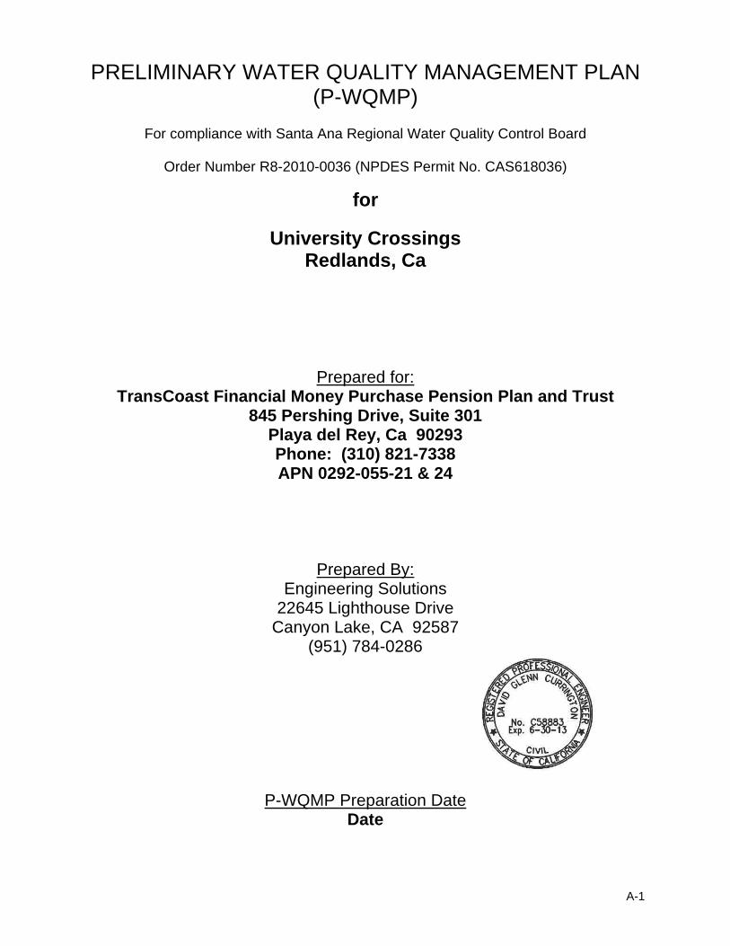
PRELIMINARY WATER QUALITY MANAGEMENT PLAN (WQMP)
PROJECT SITE INFORMATION Name of Project: __ University Crossings___________________________________ Project Location: ___Lugonia Avenue west of Alabama Street___________________ Size of Significant Re-Development on an Already Developed Site (in feet2): 547,941_ Size of New Development (in feet2): _______________________________________ Number of Home Subdivisions: ___306 Units plus one Clubhouse________________ SIC Codes: ____6513___________________________________________________ Erosive Site Conditions?: ___No___________________________________________ Natural Slope More Than 25%?: ___No_____________________________________
A-3
PRELIMINARY WATER QUALITY MANAGEMENT PLAN
(P-WQMP)
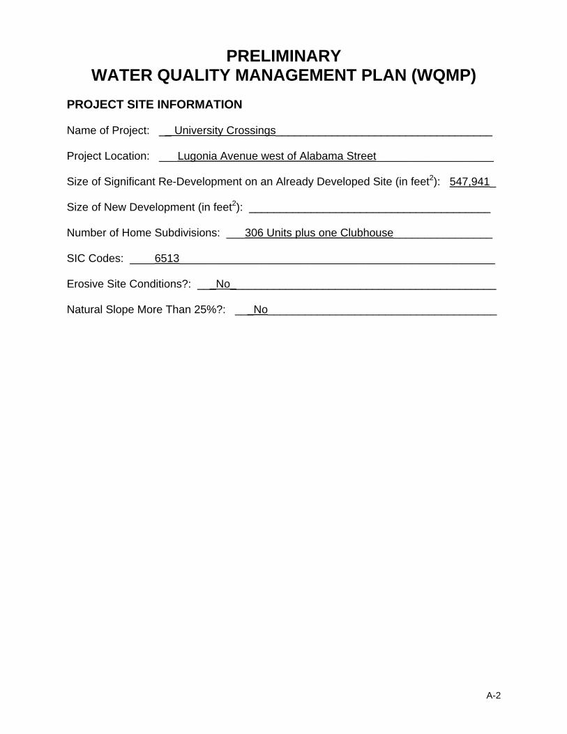
Check the appropriate project category below:
1. All significant re-development projects. Significant re-development is defined as the addition or creation of 5,000 or more square feet of impervious surface on an already developed site. This includes, but is not limited to, additional buildings and/or structures, extension of existing footprint of a building, construction of parking lots, etc. Where redevelopment results in an increase of less than fifty percent of the impervious surfaces of a previously existing development, and the existing development was not subject to WQMP requirements, the numeric sizing criteria discussed below applies only to the addition or replacement, and not to the entire development. Where redevelopment results in an increase of fifty percent or more of the impervious surfaces of a previously existing development, the numeric sizing criteria applies to the entire development.
X
2. New development projects that create 10,000 square feet or more of impervious surface (collectively over the entire project site) including commercial, industrial, residential housing subdivisions (i.e., detached single family home subdivisions, multi-family attached subdivisions or townhomes, condominiums, apartments, etc.), mixed-use, and public projects. This category includes development projects on public and private land, which fall under the planning and building authority of the jurisdiction where the projects are located.
3. Automotive repair shops (with SIC codes 5013, 5014, 5541, 7532 - 7534, 7536 - 7539).
4. Restaurants (with SIC code 5812) where the land area of development is 5,000 square feet or more.
5. All hillside developments of 5,000 square feet or more which are located
on areas with known erosive soil conditions or where the natural slope is twenty-five percent or more.
6. Developments of 2,500 square feet of impervious surface or more adjacent to (within 200 feet) or discharging directly into environmentally sensitive areas (ESAs), such as areas designated in the Ocean Plan as areas of special biological significance or waterbodies listed on the CWA Section 303(d) list of impaired waters(1).
X 7. Parking lots of 5,000 square feet or more exposed to storm water. Parking
lot is defined as land area or facility for the temporary storage of motor vehicles.
8. Retail Gasoline Outlets (RGOs) that are either 5,000 square feet or more, or have a projected average daily traffic of 100 or more vehicles per day.
The project does not fall into any of the categories described above. It is therefore defined as a Non-Category Project. NOTE: Emergency public safety projects in any of the above-listed categories shall be excluded from the WQMP requirement, if the delay caused due to the WQMP requirement compromises public safety, public health, and / or environmental protection.
(1) – For additional information regarding impaired waters, see:
http://www.waterboards.ca.gov/water_issues/programs/tmdl/integrated2010.shtml?wbid=CAR6282000020080816195148

A-4
Section 1 Introduction and Project Description 1.1 Project Information
TransCoast Financial Money Purchase Pension Plan & Trust 845 Pershing Drive, Suite 301, Playa del Rey CA, 90293
Contact: Carlyle Davis Ph. 310-821-7338 1.2 Permits
This project is located in Lot 6 of Block 5 of the Henry L. Williams Tract.
Waste discharge identification numbers (WDIDs) to be included in Final Water Quality Management Plan Submittal. No other permits are known to be required
1.3 Project Description
This project is a new development that creates 10,000 square feet or more of impervious surface (collectively over the entire project site) in the form of apartments, access driveways and parking. This project will create parking lots of 5,000 square feet or more exposed to storm water. This project is being developed on private land. The proposed project is for 306 apartment units, arranged in 19 buildings, including a clubhouse and 4.31 areas of landscape and recreation area on 12.32 acres (net). Building sizes are shown below. See Attachment F for building locations and type.
Total Building Footprint (SQ FT)
Building Type Square Feet Quantity Total Square
Feet Acres
Type I 11,902 2 23,804 0.55 Type II 13.034 4 52,136 1.20 Type III 2,530 8 20,240 0.46 Type IV 10,120 2 20,240 0.46 Type V 11,194 1 11,194 0.26 Type VI 11,461 2 22,922 0.53
Clubhouse 10,534 1 10,534 0.24 Total SQ FT 161,070 3.70
There is no POA or HOA proposed, since these will be apartments, not condos or town homes. Maintenance responsibility will be by the apartment management/ownership.
A-5
The location map and a vicinity map for this project can be found in Attachment E. A site plan identifying storm drain facilities and structures, structural BMPs, stormwater flow (drainage), and the receiving waters is included in Attachment F.
1.3 Site Description
This site is currently bounded on the north by orchards and farm land. The orchards and farmland does not appear be well maintained or in commercial use. On the East, the project is bounded by an existing commercial development including restaurants, retail shopping and department stores. To the south the project is bounded by Lugonia Avenue, a major thoroughfare for the City of Redlands. Across the avenue are several small shops, the DMV and vacant fields. To the West the site is bounded by vacant fields. This project drains to a City of Redlands storm drain pipe in Lugonia Avenue and then to the Mission Channel and finally into the Santa Ana River. This project is located in the Santa Ana River Hydrologic Unit, being a portion of the Upper Santa Ana River Hydrologic Area and within the Bunker Hill Hydrologic Sub-Area. The Santa Ana River Hydrologic Unit Watershed Area being 124791 acres in area and having an average annual rainfall of 25.1 inches. There are no known water quality problems within this project’s direct receiving water, however, the Santa Ana River, Reach 4, is impaired for pathogens. Further downstream, Reach 3 of the Santa Ana River is impaired for pathogens and metals.

A-6
Section 2 Pollutants of concern and hydrologic conditions of concern 2.1 Pollutants of Concern (NOT REQUIRED FOR NON-CATEGORY PROJECTS)
Pollutant of Concern Summary Table identifies the potential pollutants expected to be generated by the development. All expected pollutants of concern for the project site are listed as well.
Pollutant of Concern Summary Table
Pollutant Type Expected Potential Listed for Receiving Water
Bacteria/Virus X Reach 4 of Santa Ana River and Reach 3 of Santa Ana River
Metals X Reach 3 of Santa Ana River
Nutrients / Noxious Aquatic Plants X Pesticides / PCBs X Organic Compounds X Sediments / Total Suspended Solids / pH X Trash & Debris X Oxygen Demanding Substances X Oil & Grease X Other—specify pollutant(s): X
Attachment A WQMP Template
Revised February 14, 2012
A-7
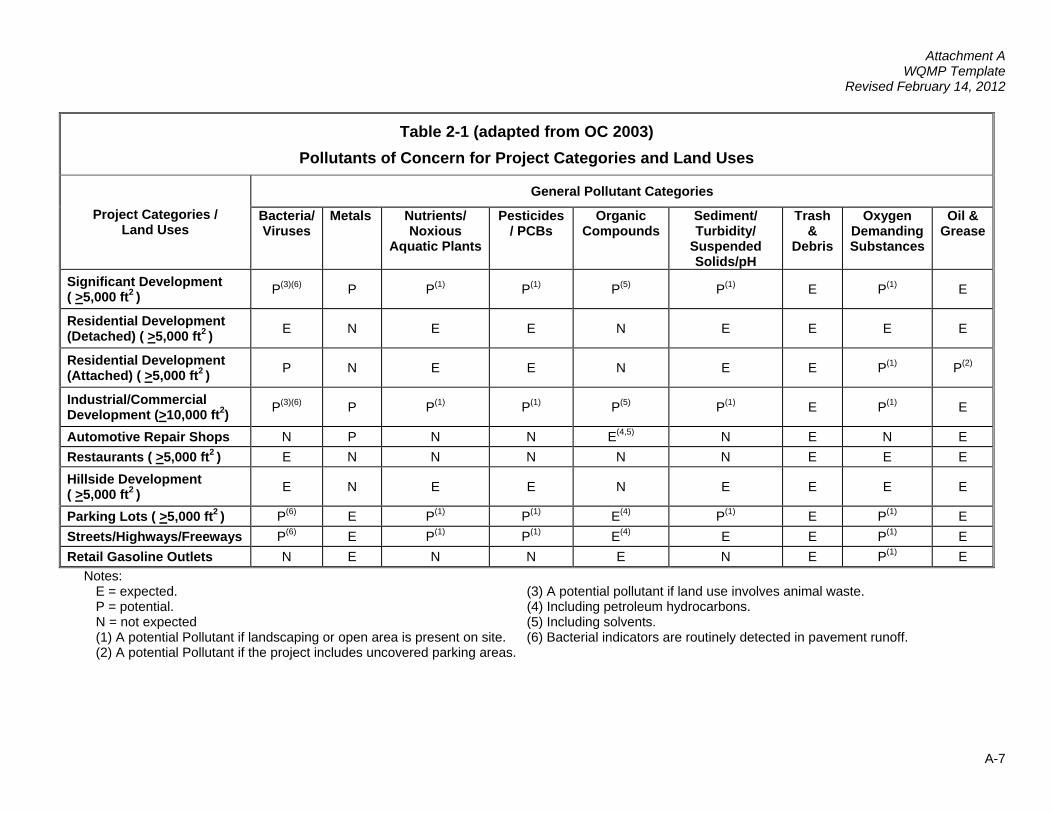
Table 2-1 (adapted from OC 2003) Pollutants of Concern for Project Categories and Land Uses
General Pollutant Categories
Project Categories / Land Uses
Bacteria/Viruses
Metals Nutrients/ Noxious
Aquatic Plants
Pesticides / PCBs
Organic Compounds
Sediment/ Turbidity/
Suspended Solids/pH
Trash &
Debris
Oxygen Demanding Substances
Oil & Grease
Significant Development ( >5,000 ft2 ) P(3)(6) P P(1) P P P(1) (5) (1) E P(1) E
Residential Development (Detached) ( >5,000 ft2 ) E N E E N E E E E
Residential Development (Attached) ( >5,000 ft2 ) P N E E N E E P(1) P(2)
Industrial/Commercial Development (>10,000 ft2) P(3)(6) P P(1) P P P(1) (5) (1) E P(1) E
Automotive Repair Shops N P N N E(4,5) N E N E Restaurants ( >5,000 ft2 ) E N N N N N E E E
Hillside Development ( >5,000 ft2 ) E N E E N E E E E
Parking Lots ( >5,000 ft2 ) P(6) E P(1) P E P(1) (4) (1) E P(1) E Streets/Highways/Freeways P(6) E P(1) P E(1) (4) E E P(1) E Retail Gasoline Outlets N E N N E N E P(1) E
Notes: E = expected. (3) A potential pollutant if land use involves animal waste.
P = potential. (4) Including petroleum hydrocarbons. N = not expected (5) Including solvents. (1) A potential Pollutant if landscaping or open area is present on site. (6) Bacterial indicators are routinely detected in pavement runoff. (2) A potential Pollutant if the project includes uncovered parking areas.
Attachment A WQMP Template
Revised February 14, 2012
A-8
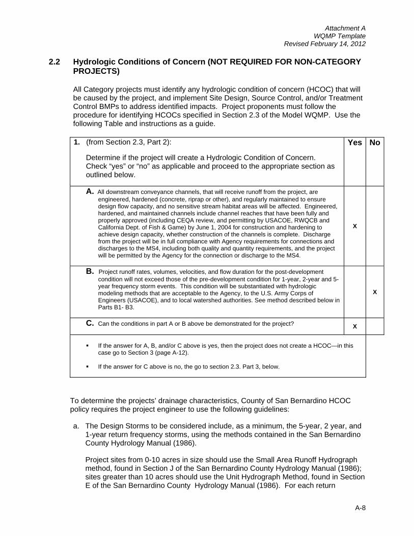
2.2 Hydrologic Conditions of Concern (NOT REQUIRED FOR NON-CATEGORY PROJECTS)
All Category projects must identify any hydrologic condition of concern (HCOC) that will be caused by the project, and implement Site Design, Source Control, and/or Treatment Control BMPs to address identified impacts. Project proponents must follow the procedure for identifying HCOCs specified in Section 2.3 of the Model WQMP. Use the following Table and instructions as a guide.
1. (from Section 2.3, Part 2):
Determine if the project will create a Hydrologic Condition of Concern. Check “yes” or “no” as applicable and proceed to the appropriate section as outlined below.
Yes No
A. All downstream conveyance channels, that will receive runoff from the project, are engineered, hardened (concrete, riprap or other), and regularly maintained to ensure design flow capacity, and no sensitive stream habitat areas will be affected. Engineered, hardened, and maintained channels include channel reaches that have been fully and properly approved (including CEQA review, and permitting by USACOE, RWQCB and California Dept. of Fish & Game) by June 1, 2004 for construction and hardening to achieve design capacity, whether construction of the channels is complete. Discharge from the project will be in full compliance with Agency requirements for connections and discharges to the MS4, including both quality and quantity requirements, and the project will be permitted by the Agency for the connection or discharge to the MS4.
X
B. Project runoff rates, volumes, velocities, and flow duration for the post-development condition will not exceed those of the pre-development condition for 1-year, 2-year and 5-year frequency storm events. This condition will be substantiated with hydrologic modeling methods that are acceptable to the Agency, to the U.S. Army Corps of Engineers (USACOE), and to local watershed authorities. See method described below in Parts B1- B3.
X
C. Can the conditions in part A or B above be demonstrated for the project?
X
If the answer for A, B, and/or C above is yes, then the project does not create a HCOC—in this
case go to Section 3 (page A-12).
If the answer for C above is no, the go to section 2.3. Part 3, below.
To determine the projects’ drainage characteristics, County of San Bernardino HCOC policy requires the project engineer to use the following guidelines:
a. The Design Storms to be considered include, as a minimum, the 5-year, 2 year, and 1-year return frequency storms, using the methods contained in the San Bernardino County Hydrology Manual (1986).
Project sites from 0-10 acres in size should use the Small Area Runoff Hydrograph method, found in Section J of the San Bernardino County Hydrology Manual (1986); sites greater than 10 acres should use the Unit Hydrograph Method, found in Section E of the San Bernardino County Hydrology Manual (1986). For each return
A-9
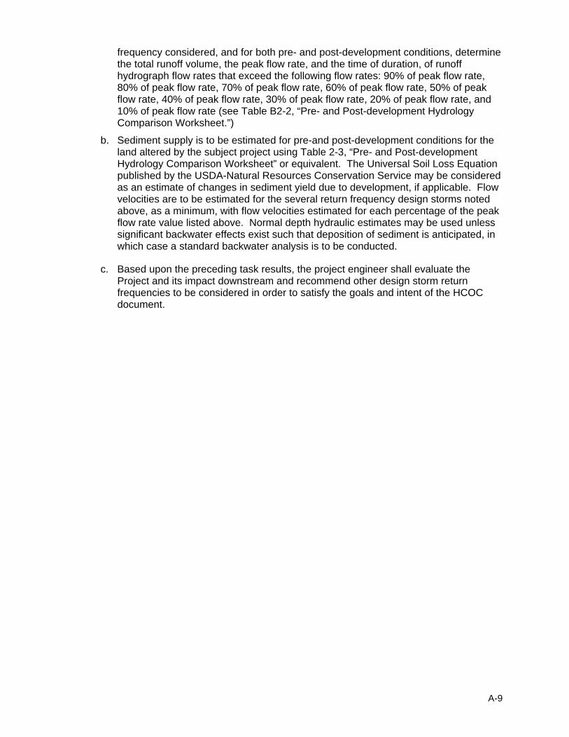
frequency considered, and for both pre- and post-development conditions, determine the total runoff volume, the peak flow rate, and the time of duration, of runoff hydrograph flow rates that exceed the following flow rates: 90% of peak flow rate, 80% of peak flow rate, 70% of peak flow rate, 60% of peak flow rate, 50% of peak flow rate, 40% of peak flow rate, 30% of peak flow rate, 20% of peak flow rate, and 10% of peak flow rate (see Table B2-2, “Pre- and Post-development Hydrology Comparison Worksheet.”)
b. Sediment supply is to be estimated for pre-and post-development conditions for the land altered by the subject project using Table 2-3, “Pre- and Post-development Hydrology Comparison Worksheet” or equivalent. The Universal Soil Loss Equation published by the USDA-Natural Resources Conservation Service may be considered as an estimate of changes in sediment yield due to development, if applicable. Flow velocities are to be estimated for the several return frequency design storms noted above, as a minimum, with flow velocities estimated for each percentage of the peak flow rate value listed above. Normal depth hydraulic estimates may be used unless significant backwater effects exist such that deposition of sediment is anticipated, in which case a standard backwater analysis is to be conducted.
c. Based upon the preceding task results, the project engineer shall evaluate the Project and its impact downstream and recommend other design storm return frequencies to be considered in order to satisfy the goals and intent of the HCOC document.
Attachment A WQMP Template
Revised February 14, 2012
A-10
Table B2-2: Pre- and Post-development Hydrology Comparison Worksheet
Total Volume Peak Flow Flow Time Duration Sediment Transport Return Period Pre Post Pre Post % of Peak Pre Post Pre Post
9080 70 60 50 40 30 20
1-year
10 9080 70 60 50 40 30 20
2-year
10 9080 70 60 50 40 30 20
5-year
10
Attachment A WQMP Template
Revised February 14, 2012
A-11
2. (from Section 2.3, Part 3): The WQMP for projects that create a HCOC must include an evaluation of whether the project will adversely impact downstream erosion, sedimentation or stream habitat. The Agency may require that the evaluation be conducted by a registered civil engineer in the State of California, with experience in fluvial geomorphology. Perform the required evaluation asspecified in A – F below. Check the boxes “yes” or “no” to verify a complete report and proceed to appropriate section based on results.
Does the evaluation include: Yes No A. An evaluation of potential impacts to all downstream channel reaches.
B. Consideration of the hydrology of the entire watershed. Review all applicable drainage area master plans to the extent available, to identify BMP requirements for new development that address cumulative inputs from development in the watershed.
C. Consultation with all applicable agencies including the USACOE; local watershed authorities (e.g. San Timoteo Watershed Management Authority and SAWPA [Santa Ana Watershed Project Authority]); U.S. Geological Survey (USGS); California Dept. of Fish & Game (CDFG); and the San Bernardino County Flood Control District; to determine any areas of potential hydrologic impact.
D. An evaluation of any available hydrologic modeling results. Modeling may have been performed by USGS, USACOE, local watershed authorities, the San Bernardino County Flood Control District, or other local jurisdiction.
E. A field reconnaissance to evaluate any natural or partially natural downstream reaches, or other sensitive habitat. The field reconnaissance must evaluate representative downstream conditions, including undercutting erosion, slope/bank stability, vegetative stress (due to flooding, erosion, water quality degradation, or loss of water supplies), and the area’s susceptibility to adverse impacts resulting from an altered flow regime or change in sediment supply and/or sediment transport .
F. A report that summarizes the findings of evaluation components A through E above, and that considers the project’s location, topography, soil and vegetation conditions, proportion of impervious surfaces, natural and infrastructure drainage features, and any other relevant hydrologic and environmental factors to be protected specific to the project’s watershed. The report must provide a determination of whether the project will adversely impact any downstream erosion, sedimentation or stream habitat, and identify any areas where adverse impacts are expected.
Is the report required by 2.3, Part 3.f complete? (Attach the report) If not, perform the required evaluation and add to the report.
Does the report determine that the project will have an adverse downstream impact?
If yes, then go to Section 2.3, Part 4, below.
If no, then go to Section 3.

3. (from Section 2.3, Part 4): If the evaluation specified in (3) above, determines that adverse impacts to downstream erosion, sedimentation or stream habitat will occur, then the project proponent must perform the requirements specified in A, B, and C, below. Check the boxes “yes” or “no” to verify all requirements have been completed.
YES NO
A. Conduct hydrologic modeling of the project and the potentially impacted areas, according to modeling standards recommended by the Agency or local watershed authority, for the 1-year, 2-year, and 5-year frequency storm events, at a minimum. Hydrologic modeling results must include determination of peak flow rate, flow velocity, runoff volume, time of concentration, and retention volume for the project area.
B. Ensure that the project will be consistent with any approved master plans of drainage or analogous plans or programs.
C. Implement Site Design BMPs as specified in Section 2.5.1, and recommend any additional BMPs that will be implemented to mitigate the adverse impacts identified in (3.F) above.
Are the requirements for Section 2.3 Part 4 adequate? (Attach report/results) Has the project proponent recommended BMPs to mitigate any impacts based on the modeling? If yes, then list/describe BMPs: If no, then explain how mitigation will be achieved: Will the BMPs be effective? Does the Agency have any additional requirements? Verify with Agency before submitting the project WQMP.
2.3 Watershed Impact Of Project
The project proponent must include in the project WQMP:
An evaluation of the pollutants of concern and/or hydrologic conditions of concern associated with the project, and a determination of whether the project will cause any significant impact(s) to any downstream receiving waters, alone or in conjunction with other projects in the watershed.
A description of how any adverse impacts will effectively be mitigated through the incorporation and implementation of BMPs.
A-12

Section 3 Best Management Practice Selection Process 3.1 Site Design BMPs
For listed Site Design BMPs, indicate in the following table whether it will be used (yes/no) and describe how used, or, if not used, provide justification/alternative. Provide detailed descriptions of planned Site Design BMPs, if applicable.
A-13
1. Minimize Stormwater Runoff, Minimize Project’s Impervious Footprint, and Conserve Natural Areas
Maximize the permeable area. This can be achieved in various ways, including but not limited to, increasing building density (number of stories above or below ground) and developing land use regulations seeking to limit impervious surfaces. Yes X No Describe actions taken or justification/alternative: This project uses two story apartments to increase the building density and maximize the permeable area. Only the covered parking and clubhouse are one story buildings. The building density achieved by this design is 24.8 DU/AC Runoff from developed areas may be reduced by using alternative materials or surfaces with a lower Coefficient of Runoff, or “C-Factor”. Yes X No Describe actions taken or justification/alternative: Alternate materials with a lower “C-Factor” are not being utilized as part of this project because of durability issues with the pervious pavement and the increased cost of installation and maintenance. Surfaces, such as turf and other landscaping plants, with a “C-factor” lower than sidewalk and pavement, is being used in open spaces to the maximum extent practicable. In addition to having a lower “C-Factor” than other ground covers (concrete or asphalt), turf and other landscaping plants has the added advantage of capturing a portion of the rainfall. The Recreational areas, such as the volley ball court and play grounds were chosen because of their extremely low “C-Factor”. Conserve natural areas. This can be achieved by concentrating or clustering development on the least environmentally sensitive portions of a site while leaving the remaining land in a natural, undisturbed condition. Yes No X Describe actions taken or justification/alternative: This project is located in an area that has been used for agriculture and has been graded for pads in the past. No natural areas are left.
A-14
Construct walkways, trails, patios, overflow parking lots, alleys, driveways, low-traffic streets, and other low-traffic areas with open-jointed paving materials or permeable surfaces, such as pervious concrete, porous asphalt, unit pavers, and granular materials. Yes No X Describe actions taken or justification/alternative: Due to the nature of this development, the paved areas would be subject to large heavy loads (including the parking stalls) and it was felt that the durability of pervious pavement and the limited areas where it might be placed did not warrant its use. Instead more landscape area was created. Construct streets, sidewalks, and parking lot aisles to the minimum widths necessary, provided that public safety and a pedestrian friendly environment are not compromised1. Incorporate landscaped buffer areas between sidewalks and streets. Yes X No Describe actions taken or justification/alternative: Streets and sidewalks are constructed to the minimum requirements of the governing agencies. Meandering sidewalk along Lugonia Avenue incorporated a buffer strip between it and the street. Reduce widths of street where off-street parking is available2. Yes No X Describe actions taken or justification/alternative: Streets and sidewalks are constructed to the minimum requirements of the governing agencies Maximize canopy interception and water conservation by preserving existing native trees and shrubs, and planting additional native or drought tolerant trees and large shrubs. Yes No X Describe actions taken or justification/alternative: This project is located in an area that has been used for agriculture and has been graded for pads in the past. No native trees or shrubs are left. Landscaping for this project will include native and drought tolerant trees and large shrubs.
1 Sidewalk widths must still comply with Americans with Disabilities Act regulations and other life safety requirements. 2 However, street widths must still comply with life safety requirements for fire and emergency vehicle access.
A-15

Other comparable site design options that are equally effective. Yes X No Describe actions taken or justification/alternative: Water quality basins have been created through out the site to provide more landscaped space near each hardscaped area. Minimize the use of impervious surfaces, such as decorative concrete, in the landscape design. Yes X No Describe actions taken or justification/alternative: The use of decorative concrete in landscaped areas has been minimized and where it has been used it is installed as part of the sidewalk system. Use natural drainage systems. Yes No X Describe actions taken or justification/alternative: This project is located in an area that has been used for agriculture and has been graded for pads in the past. No natural drain systems are left. Where soils conditions are suitable, use perforated pipe or gravel filtration pits for low flow infiltration3. Yes No X Describe actions taken or justification/alternative: Infiltration basins will be used for low flow infiltration. Construct onsite ponding areas, rain gardens, or retention facilities to increase opportunities for infiltration, while being cognizant of the need to prevent the development of vector breeding areas. Yes X No Describe actions taken or justification/alternative: Infiltration basins have been located around the site and designed to drain within 48 hours.
A-16
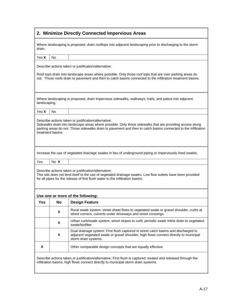
2. Minimize Directly Connected Impervious Areas Where landscaping is proposed, drain rooftops into adjacent landscaping prior to discharging to the storm drain. Yes X No Describe actions taken or justification/alternative: Roof tops drain into landscape areas where possible. Only those roof tops that are over parking areas do not. Those roofs drain to pavement and then to catch basins connected to the infiltration treatment basins. Where landscaping is proposed, drain impervious sidewalks, walkways, trails, and patios into adjacent landscaping. Yes X No Describe actions taken or justification/alternative: Sidewalks drain into landscape areas where possible. Only those sidewalks that are providing access along parking areas do not. Those sidewalks drain to pavement and then to catch basins connected to the infiltration treatment basins. Increase the use of vegetated drainage swales in lieu of underground piping or imperviously lined swales. Yes No X Describe actions taken or justification/alternative: This site does not lend itself to the use of vegetated drainage swales. Low flow outlets have been provided for all pipes for the release of first flush water to the infiltration basins. Use one or more of the following: Yes No Design Feature
X Rural swale system: street sheet flows to vegetated swale or gravel shoulder, curbs at street corners, culverts under driveways and street crossings
X Urban curb/swale system; street slopes to curb; periodic swale inlets drain to vegetated swale/biofilter.
X Dual drainage system: First flush captured in street catch basins and discharged to adjacent vegetated swale or gravel shoulder, high flows connect directly to municipal storm drain systems.
X Other comparable design concepts that are equally effective.
Describe actions taken or justification/alternative: First flush is captured, treated and released through the infiltration basins, high flows connect directly to municipal storm drain systems.
A-17

Use one or more of the following features for design of driveways and private residential parking areas:
Yes No Design Feature
X Design driveways with shared access, flared (single lane at street) or wheel strips (paving only under tires); or, drain into landscaping prior to discharging to the municipal storm drain system.
X Uncovered temporary or guest parking on private residential lots may be paved with a permeable surface; or designed to drain into landscaping prior to discharging to the municipal storm drain system.
X Other comparable design concepts that are equally effective.
Describe actions taken or justification/alternative: Flow from driveways is collected and drains into landscaped areas and infiltration basins. Uncovered guest parking is collected and drains into landscaped areas and infiltration basins. See Attachment G for Landscape areas exhibit.
Use one or more of the following design concepts for the design of parking areas:
Yes No Design Feature
X Where landscaping is proposed in parking areas, incorporate landscape areas into the drainage design.
X Overflow parking (parking stalls provided in excess of the Agency’s minimum parking requirements) may be constructed with permeable paving.
X Other comparable design concepts that are equally effective.
Describe actions taken or justification/alternative: Where possible, landscaping next to parking areas is used in the drainage design, otherwise the runoff is collected by catch basins and storm drain then conveyed and treated in the infiltration basins. Due to the nature of this development, the paved areas would be subject to large heavy loads (including the parking stalls) and it was felt that the durability of pervious pavement and the limited areas where it might be placed did not warrant its use. Instead more landscape area was created.
A-18
3.2 Source Control BMPs
Complete the following selection table for Source Control BMPs, by checking boxes that are applicable. All listed BMPs shall be implemented for the project. Where a required Source Control BMP is not applicable to the project due to project characteristics, justification and/or alternative practices for preventing pollutants must be provided. In addition to completing the following tables, provide detailed descriptions on the implementation of planned Source Control BMPs.
A-19

A-20
Source Control BMP Selection Matrix*
Source Control BMPs
Project Category E
duca
tion
of P
rope
rty O
wne
rs
Act
ivity
Res
trict
ions
Spi
ll C
ontin
genc
y P
lan
Em
ploy
ee T
rain
ing/
Edu
catio
n P
rogr
am
Stre
et S
wee
ping
Priv
ate
Stre
et
and
Par
king
Lot
s
Com
mon
Are
as C
atch
Bas
in
Insp
ectio
n
Land
scap
e P
lann
ing
(SD
-10)
Hill
side
Lan
dsca
ping
Roo
f Run
off C
ontro
ls (S
D-1
1)
Effi
cien
t Irr
igat
ion
(SD
-12)
Pro
tect
Slo
pes
and
Cha
nnel
s
Sto
rm D
rain
Sig
nage
(SD
-13)
Inle
t Tra
sh R
acks
Ene
rgy
Dis
sipa
ters
Tras
h S
tora
ge A
reas
(SD
-32)
an
d Li
tter C
ontro
l
Fuel
ing
Are
as (S
D-3
0)
Air/
Wat
er S
uppl
y A
rea
Dra
inag
e
Mai
nten
ance
Bay
s an
d D
ocks
(S
D-3
1)
Veh
icle
Was
hing
Are
as
(SD
-33)
Out
door
Mat
eria
l Sto
rage
A
reas
(SD
-34)
Out
door
Wor
k A
reas
(SD
-35)
Out
door
Pro
cess
ing
Are
as
(SD
-36)
Was
h W
ater
Con
trols
for F
ood
Pre
para
tion
Are
as
Per
viou
s P
avem
ent (
SD
-20)
Alte
rnat
ive
Bui
ldin
g M
ater
ials
(S
D-2
1)
Significant Redevelopment ( >5,000 ft2 )
Residential Development (Detached)( >5,000 ft2)
Residential Development (Attached) ( >5,000 ft2)
x x x x x x x x x x x x
Industrial / Commercial Development (>10,000 ft2)
Automotive Repair Shops
Restaurants ( >5,000 ft2)
Hillside Development ( >5,000 ft2)
Parking Lots ( >5,000 ft2) x x x x x x x x x x x x
Streets / Highways / Freeways
Retail Gasoline Outlets Non-Category Project
* Provide justification of each Source Control BMP that will not be incorporated in the project WQMP, or explanation of proposed equally effective alternatives in the following table.

A-21
Justification for Source Control BMPs not incorporated into the project WQMP
Source Control BMP Used in Project
(yes/no)? Justification/Alternative* Implementation Description
Education of Property Owners yes
Property owners shall receive an educational packet with information on “good house keeping”, BMP maintenance and listing those activities that are allowed and those that are not.
Activity Restrictions yes Property owners shall receive a packet listing those activities that are allowed and those that are not.
Spill Contingency Plan No Not applicable to this type of project
Not applicable to this type of project
Employee Training/Education Program
Yes
Employees shall be trained in the proper care of the drainage facilities and their maintenance by a qualified and certified instructor in water quality management.
Street Sweeping Private Street and Parking Lots
Yes
All paved areas within the site shall be swept on an as needed basis and once before the beginning of the rainy season by a qualified firm specializing in this task.
Common Areas Catch Basin Inspection Yes
Catch basin shall be inspected at the beginning of the rainy season and after each storm there after. See Attachment I for storm drain and catch basin locations.
Landscape Planning (SD-10) Yes Landscaping shall include native and
drought tolerant plants , trees and shrubs
Hillside Landscaping There are no hillsides on the site
Roof Runoff Controls (SD-11) Yes Roof drains shall be directed to landscaped
areas or treatment facilities
Efficient Irrigation (SD-12) Yes
Irrigation shall be equipped with rain sensors to prevent watering during rain events and automatic shut off valves in the event of a leak
Protect Slopes and Channels No
There are no slope or channels on this project
Storm Drain Signage (SD-13) No
All storm drain inlets shall be marked indicating “Only rain in the drain”, and "Drains to River" . Marking to be inspected once per year and repainted as needed by owner.
Inlet Trash Racks Yes
All storm drain inlets shall have grates or similar devices to keep litter from entering. Trash racks shall be inspected monthly and cleaned as needed.
Energy Dissipaters No No flows are released to channels
Trash Storage Areas (SD-32) and Litter Control
Yes
Occupants shall be provided with Information concerning the correct disposal of trash and litter. Each unit shall be assigned a specific trash enclosure and dumpster for its use.
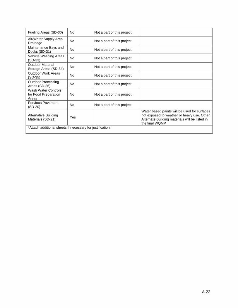
Fueling Areas (SD-30) No Not a part of this project
Air/Water Supply Area Drainage No Not a part of this project
Maintenance Bays and Docks (SD-31) No Not a part of this project
Vehicle Washing Areas (SD-33) No Not a part of this project
Outdoor Material Storage Areas (SD-34) No Not a part of this project
Outdoor Work Areas (SD-35) No Not a part of this project
Outdoor Processing Areas (SD-36) No Not a part of this project
Wash Water Controls for Food Preparation Areas
No Not a part of this project
Pervious Pavement (SD-20) No Not a part of this project
Alternative Building Materials (SD-21) Yes
Water based paints will be used for surfaces not exposed to weather or heavy use. Other Alternate Building materials will be listed in the final WQMP
*Attach additional sheets if necessary for justification.
A-22
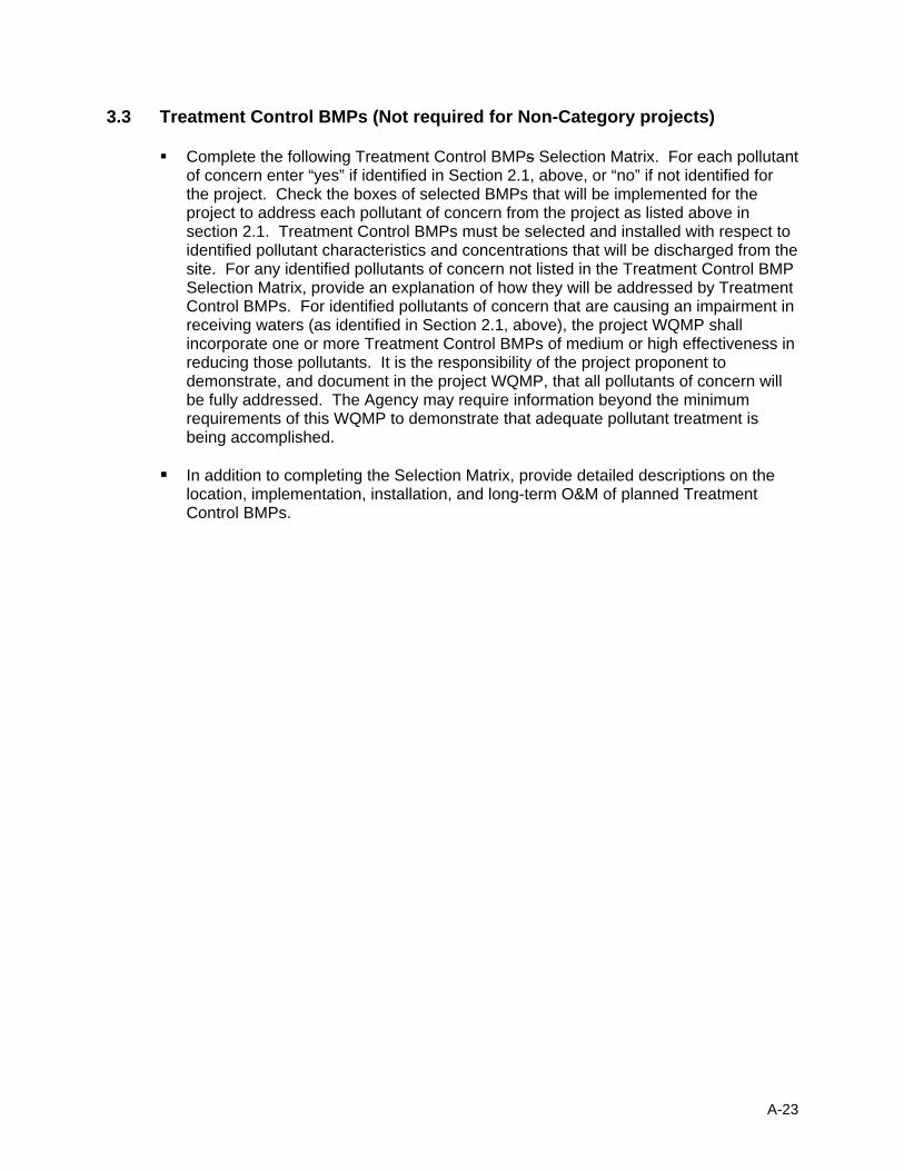
3.3 Treatment Control BMPs (Not required for Non-Category projects)
Complete the following Treatment Control BMPs Selection Matrix. For each pollutant of concern enter “yes” if identified in Section 2.1, above, or “no” if not identified for the project. Check the boxes of selected BMPs that will be implemented for the project to address each pollutant of concern from the project as listed above in section 2.1. Treatment Control BMPs must be selected and installed with respect to identified pollutant characteristics and concentrations that will be discharged from the site. For any identified pollutants of concern not listed in the Treatment Control BMP Selection Matrix, provide an explanation of how they will be addressed by Treatment Control BMPs. For identified pollutants of concern that are causing an impairment in receiving waters (as identified in Section 2.1, above), the project WQMP shall incorporate one or more Treatment Control BMPs of medium or high effectiveness in reducing those pollutants. It is the responsibility of the project proponent to demonstrate, and document in the project WQMP, that all pollutants of concern will be fully addressed. The Agency may require information beyond the minimum requirements of this WQMP to demonstrate that adequate pollutant treatment is being accomplished.
In addition to completing the Selection Matrix, provide detailed descriptions on the
location, implementation, installation, and long-term O&M of planned Treatment Control BMPs.
A-23

A-25
Treatment Control BMP Selection Matrix
Treatment Control BMP Categories
Pollutant of Concern
Biofilters Detention Basins(2)
Infiltration Basins(3)
Wet Ponds or Wetlands
Filtration Water Quality Inlets
Hydrodynamic Separator Systems (4)
Manufactured/ Proprietary
Devices
Sediment/Turbidity/ Suspended Solids/pH H/M M H/M H/M H/M L H/M
(L for turbidity) U
Yes/No? yes X Nutrients / Noxious Aquatic Plants L M H/M H/M L/M L L U
Yes/No? yes X
Organic Compounds U U U U H/M L L U
Yes/No? yes X
Trash & Debris L M U U H/M M H/M U
Yes/No? yes X Oxygen Demanding Substances L M H/M H/M H/M L L U
Yes/No? yes X
Bacteria & Viruses U U H/M U H/M L L U
Yes/No? yes X
Oils & Grease H/M M U U H/M M L/M U
Yes/No? yes X Pesticides (non-soil bound)/PCBs U U U U U L L U
Yes/No? yes X
Heavy Metals H/M M H H H L L U
Yes/No? yes X
3.4 BMP Design Criteria
A-26
The following Treatment Control BMP(s) (Flow Based or Volume Based) will be implemented for this project (check “Implemented” box, if used):
Design Basis of Treatment Control BMPs
Implemented Treatment Control BMP Design Basis
Vegetated Buffer Strips
Vegetated Swale
Multiple Systems
Manufactured/Proprietary
Flow Based
Bioretention
Wet Pond
Constructed Wetland
Extended Detention Basin
Water Quality Inlet
Retention/Irrigation
X Infiltration Basin
Infiltration Trench
Media Filter
Manufactured/Proprietary
Volume Based
3.4.1 Flow Based Design Criteria
Calculate the BMP design flow by using the method described in Attachment D, Section A. Show calculations in detail—attach a separate sheet of calculations.
3.4.2 Volume-Based Design Criteria
Calculate the required capture volume of the BMP using the method described in Attachment D, Section B. Show calculations in detail—attach a separate sheet of calculations.
Section 4 Operation and Maintenance 4.1 Operations and Maintenance
Operation and maintenance (O&M) requirements for all Source Control, Site Design, and Treatment Control BMPs shall be identified within the WQMP. The WQMP shall include the following:
4.1.1 O&M Description and Schedule:
List and identify each BMP that requires O&M.
Provide a thorough description of O&M activities (include the O&M
process, and the handling and placement of any wastes). Include BMP start-up dates.
Provide a schedule of the frequency of O&M for each BMP.
4.1.2 Inspection & Monitoring Requirements:
Provide thorough descriptions of water quality monitoring (if locally required).
Provide self-inspections and record keeping requirements for BMPs (review
local specific requirements regarding self-inspections and/or annual reporting), including identification of responsible parties for inspection and record keeping.
4.1.3 Identification of Responsible Parties:
Provide the party or parties that will be responsible for each BMP O&M. For
each responsible party, include the party’s name, address, contact name and telephone number.
A-27

BMP Responsible
Party
Implementation Date and Frequency
Education of Property Owners Property Owner Upon rental of property and once per year thereafter
Activity Restrictions Property Owner Upon rental of property and once per year thereafter
Employee Training/Education Program
Property Owner Within 6 months of hiring and yearly thereafter
Street Sweeping Private Street and Parking Lots
Property Owner Upon issuance of CERTIFICATE OF OCCUPANCY and then as-needed and once before the beginning of each rainy season*
Common Areas Catch Basin Inspection
Property Owner Upon issuance of CERTIFICATE OF OCCUPANCY and at the beginning of the rainy season* and each storm there after
Landscape Planning (SD-10) Property Owner Monthly after planting with replacement as needed
Roof Runoff Controls (SD-11) Property Owner Upon issuance of CERTIFICATE OF OCCUPANCY and at the beginning of the rainy season* and each storm there after
Efficient Irrigation (SD-12) Property Owner Upon issuance of CERTIFICATE OF OCCUPANCY and monthly thereafter
Storm Drain Signage (SD-13) Property Owner Upon issuance of CERTIFICATE OF OCCUPANCY and twice yearly thereafter
Inlet Trash Racks Property Owner Upon issuance of CERTIFICATE OF OCCUPANCY and at the beginning of the rainy season* and each storm there after
Trash Storage Areas (SD-32) and Litter Control
Property Owner Upon issuance of CERTIFICATE OF OCCUPANCY and weekly thereafter
Alternative Building Materials (SD-21)
Property Owner Upon issuance of CERTIFICATE OF OCCUPANCY and then as-needed and once before the beginning of each rainy season*
*The rainy season shall be considered as from November through March
A-28
Section 5 Funding 5.1 Funding
The Permit requires that for all Treatment Control BMPs, a funding source or sources for operation and maintenance of each BMP be identified within the WQMP. Project proponents must:
Indicate funding sources or sources for O&M for this project. For each funding source, include the responsible party’s name, address, contact name and telephone number.
A-29
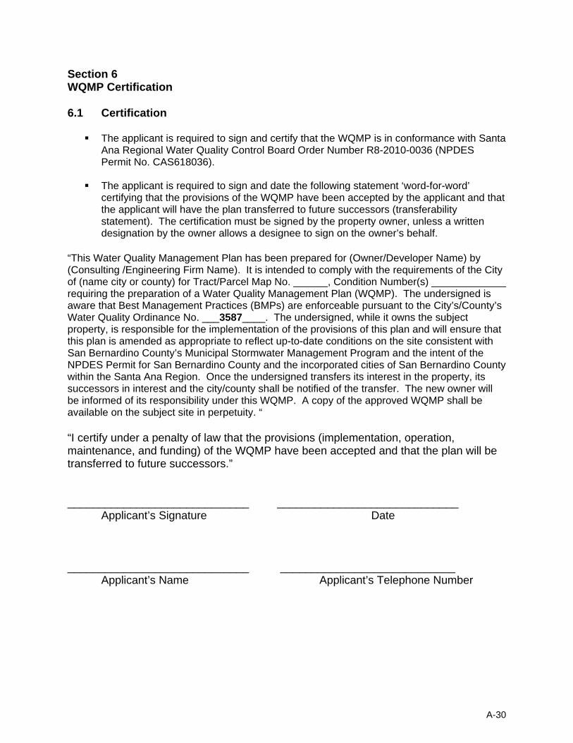
Section 6 WQMP Certification 6.1 Certification
The applicant is required to sign and certify that the WQMP is in conformance with Santa
Ana Regional Water Quality Control Board Order Number R8-2010-0036 (NPDES Permit No. CAS618036).
The applicant is required to sign and date the following statement ‘word-for-word’ certifying that the provisions of the WQMP have been accepted by the applicant and that the applicant will have the plan transferred to future successors (transferability statement). The certification must be signed by the property owner, unless a written designation by the owner allows a designee to sign on the owner’s behalf.
“This Water Quality Management Plan has been prepared for (Owner/Developer Name) by (Consulting /Engineering Firm Name). It is intended to comply with the requirements of the City of (name city or county) for Tract/Parcel Map No. ______, Condition Number(s) _____________ requiring the preparation of a Water Quality Management Plan (WQMP). The undersigned is aware that Best Management Practices (BMPs) are enforceable pursuant to the City’s/County’s Water Quality Ordinance No. ___3587____. The undersigned, while it owns the subject property, is responsible for the implementation of the provisions of this plan and will ensure that this plan is amended as appropriate to reflect up-to-date conditions on the site consistent with San Bernardino County’s Municipal Stormwater Management Program and the intent of the NPDES Permit for San Bernardino County and the incorporated cities of San Bernardino County within the Santa Ana Region. Once the undersigned transfers its interest in the property, its successors in interest and the city/county shall be notified of the transfer. The new owner will be informed of its responsibility under this WQMP. A copy of the approved WQMP shall be available on the subject site in perpetuity. “ “I certify under a penalty of law that the provisions (implementation, operation, maintenance, and funding) of the WQMP have been accepted and that the plan will be transferred to future successors.” _____________________________ _____________________________
Applicant’s Signature Date _____________________________ ____________________________
Applicant’s Name Applicant’s Telephone Number
A-30
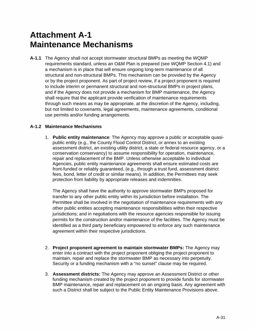
Attachment A-1 Maintenance Mechanisms
A-1.1 The Agency shall not accept stormwater structural BMPs as meeting the WQMP requirements standard, unless an O&M Plan is prepared (see WQMP Section 4.1) and a mechanism is in place that will ensure ongoing long-term maintenance of all structural and non-structural BMPs. This mechanism can be provided by the Agency or by the project proponent. As part of project review, if a project proponent is required to include interim or permanent structural and non-structural BMPs in project plans, and if the Agency does not provide a mechanism for BMP maintenance, the Agency shall require that the applicant provide verification of maintenance requirements through such means as may be appropriate, at the discretion of the Agency, including, but not limited to covenants, legal agreements, maintenance agreements, conditional use permits and/or funding arrangements.
A-1.2 Maintenance Mechanisms
1. Public entity maintenance: The Agency may approve a public or acceptable quasi-public entity (e.g., the County Flood Control District, or annex to an existing assessment district, an existing utility district, a state or federal resource agency, or a conservation conservancy) to assume responsibility for operation, maintenance, repair and replacement of the BMP. Unless otherwise acceptable to individual Agencies, public entity maintenance agreements shall ensure estimated costs are front-funded or reliably guaranteed, (e.g., through a trust fund, assessment district fees, bond, letter of credit or similar means). In addition, the Permittees may seek protection from liability by appropriate releases and indemnities.
The Agency shall have the authority to approve stormwater BMPs proposed for transfer to any other public entity within its jurisdiction before installation. The Permittee shall be involved in the negotiation of maintenance requirements with any other public entities accepting maintenance responsibilities within their respective jurisdictions; and in negotiations with the resource agencies responsible for issuing permits for the construction and/or maintenance of the facilities. The Agency must be identified as a third party beneficiary empowered to enforce any such maintenance agreement within their respective jurisdictions.
2. Project proponent agreement to maintain stormwater BMPs: The Agency may
enter into a contract with the project proponent obliging the project proponent to maintain, repair and replace the stormwater BMP as necessary into perpetuity. Security or a funding mechanism with a “no sunset” clause may be required.
3. Assessment districts: The Agency may approve an Assessment District or other
funding mechanism created by the project proponent to provide funds for stormwater BMP maintenance, repair and replacement on an ongoing basis. Any agreement with such a District shall be subject to the Public Entity Maintenance Provisions above.
A-31

4. Lease provisions: In those cases where the Agency holds title to the land in
question, and the land is being leased to another party for private or public use, the Agency may assure stormwater BMP maintenance, repair and replacement through conditions in the lease.
5. Conditional use permits: For discretionary projects only, the Agency may assure
maintenance of stormwater BMPs through the inclusion of maintenance conditions in the conditional use permit. Security may be required.
6. Alternative mechanisms: The Agency may accept alternative maintenance
mechanisms if such mechanisms are as protective as those listed above.
A-32
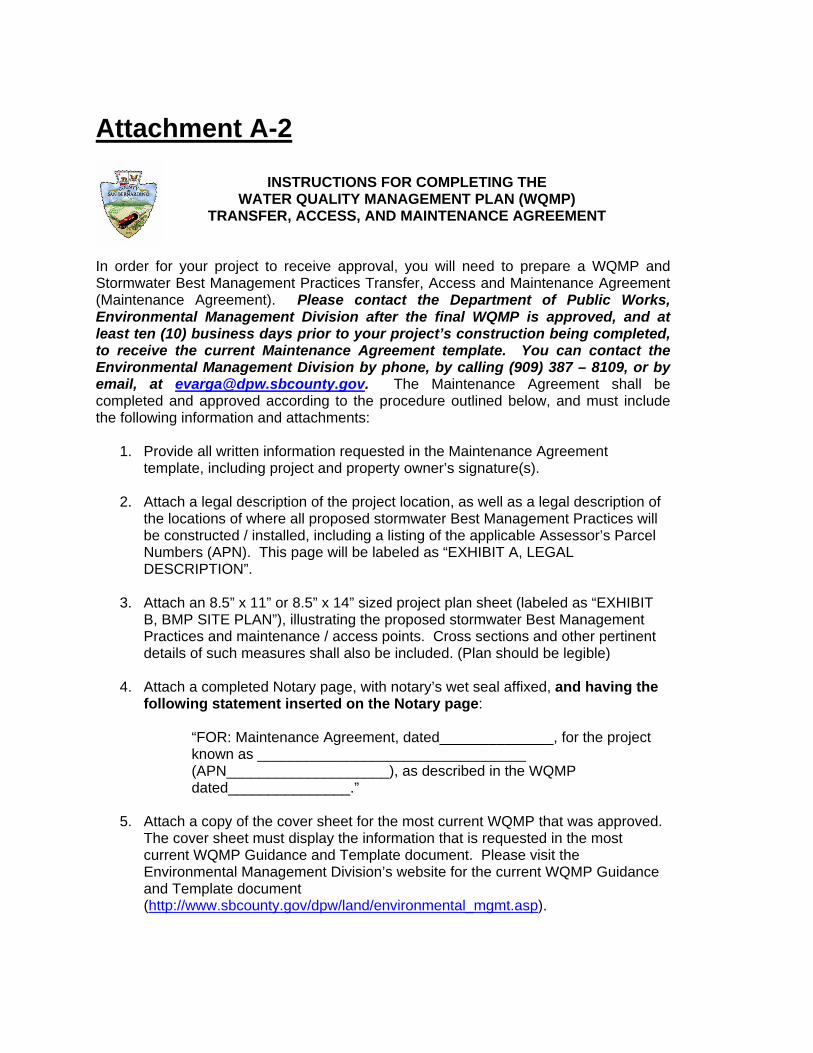
Attachment A-2
INSTRUCTIONS FOR COMPLETING THE WATER QUALITY MANAGEMENT PLAN (WQMP)
TRANSFER, ACCESS, AND MAINTENANCE AGREEMENT In order for your project to receive approval, you will need to prepare a WQMP and Stormwater Best Management Practices Transfer, Access and Maintenance Agreement (Maintenance Agreement). Please contact the Department of Public Works, Environmental Management Division after the final WQMP is approved, and at least ten (10) business days prior to your project’s construction being completed, to receive the current Maintenance Agreement template. You can contact the Environmental Management Division by phone, by calling (909) 387 – 8109, or by email, at [email protected]. The Maintenance Agreement shall be completed and approved according to the procedure outlined below, and must include the following information and attachments:
1. Provide all written information requested in the Maintenance Agreement
template, including project and property owner’s signature(s).
2. Attach a legal description of the project location, as well as a legal description of the locations of where all proposed stormwater Best Management Practices will be constructed / installed, including a listing of the applicable Assessor’s Parcel Numbers (APN). This page will be labeled as “EXHIBIT A, LEGAL DESCRIPTION”.
3. Attach an 8.5” x 11” or 8.5” x 14” sized project plan sheet (labeled as “EXHIBIT B, BMP SITE PLAN”), illustrating the proposed stormwater Best Management Practices and maintenance / access points. Cross sections and other pertinent details of such measures shall also be included. (Plan should be legible)
4. Attach a completed Notary page, with notary’s wet seal affixed, and having the following statement inserted on the Notary page:
“FOR: Maintenance Agreement, dated______________, for the project known as _________________________________ (APN____________________), as described in the WQMP dated_______________.”
5. Attach a copy of the cover sheet for the most current WQMP that was approved.
The cover sheet must display the information that is requested in the most current WQMP Guidance and Template document. Please visit the Environmental Management Division’s website for the current WQMP Guidance and Template document (http://www.sbcounty.gov/dpw/land/environmental_mgmt.asp).

6. The completed Maintenance Agreement (along with attachments) shall be submitted for review to:
Department of Public Works Environmental Management Division 825 E. Third Street, Room 201 San Bernardino, CA 92415-0835
7. Staff at the Environmental Management Division will review the Maintenance
Agreement, and request any necessary changes.
8. When the Maintenance Agreement has been approved, the project and property owner(s) must sign the Maintenance Agreement and have his / her signature notarized.
9. The Maintenance Agreement will then be returned to the Environmental Management Division, where appropriate staff will obtain the notarized signature of the Director of Public Works (this may take up to ten (10) business days, depending on the Director’s schedule and availability of the notary). Please provide a telephone number where you can be reached when the Maintenance Agreement is ready to be picked up for you to record. Please Note: The Director of Public Works will not sign the Maintenance Agreement until the proposed Best Management Practices, as documented in the project WQMP, are constructed / installed, and all outstanding charges and invoices are paid.
10. The fully executed Maintenance Agreement must now be recorded at the San Bernardino County Recorder’s Office at:
222 W. Hospitality Lane (behind the Souplantation restaurant) San Bernardino, CA 92415-0018
11. A photocopy of the final recorded Maintenance Agreement must be returned to
the Environmental Management Division. You must also show the recorded Maintenance Agreement to the Land Development Division of the Department of Public Works, in order to receive their final approval on your project.
If during project construction, there are any field changes to the stormwater Best Management Practices and maintenance / access points proposed in the WQMP, then the WQMP must be revised and re-submitted for approval by the County, and a new Maintenance Agreement must also be completed and re-submitted for approval by the County, according to the procedure outlined above.
If you have any further questions about this process, please call the Environmental Management Division, County Stormwater Program, at (909) 387-8109.
RECORDING REQUESTED BY: County of San Bernardino Department of Public Works AND WHEN RECORDED MAIL TO: County of San Bernardino Department of Public Works 825 E. Third Street, Room 201 San Bernardino, CA 92415-0835 SPACE ABOVE THIS LINE FOR RECORDER’S USE
AGREEMENT THIS PAGE ADDED TO PROVIDE ADEQUATE SPACE FOR RECORDING INFORMATION (Additional Recording Fees Apply) Page 1 of 7
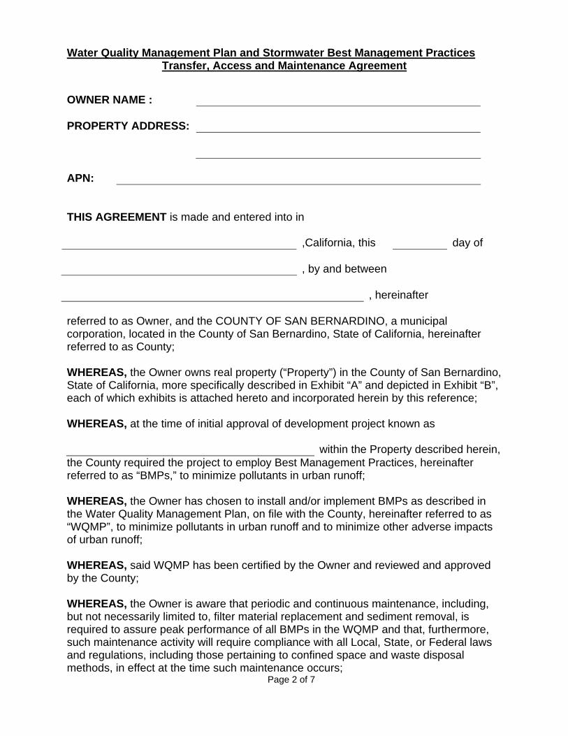
Water Quality Management Plan and Stormwater Best Management Practices Transfer, Access and Maintenance Agreement
OWNER NAME : PROPERTY ADDRESS: APN: THIS AGREEMENT is made and entered into in ,California, this day of , by and between , hereinafter referred to as Owner, and the COUNTY OF SAN BERNARDINO, a municipal corporation, located in the County of San Bernardino, State of California, hereinafter referred to as County; WHEREAS, the Owner owns real property (“Property”) in the County of San Bernardino, State of California, more specifically described in Exhibit “A” and depicted in Exhibit “B”, each of which exhibits is attached hereto and incorporated herein by this reference; WHEREAS, at the time of initial approval of development project known as within the Property described herein,
the County required the project to employ Best Management Practices, hereinafter referred to as “BMPs,” to minimize pollutants in urban runoff; WHEREAS, the Owner has chosen to install and/or implement BMPs as described in the Water Quality Management Plan, on file with the County, hereinafter referred to as “WQMP”, to minimize pollutants in urban runoff and to minimize other adverse impacts of urban runoff; WHEREAS, said WQMP has been certified by the Owner and reviewed and approved by the County; WHEREAS, the Owner is aware that periodic and continuous maintenance, including, but not necessarily limited to, filter material replacement and sediment removal, is required to assure peak performance of all BMPs in the WQMP and that, furthermore, such maintenance activity will require compliance with all Local, State, or Federal laws and regulations, including those pertaining to confined space and waste disposal methods, in effect at the time such maintenance occurs; Page 2 of 7

NOW THEREFORE, it is mutually stipulated and agreed as follows: 1. All maintenance or replacement of BMPs proposed as part of the WQMP are the
sole responsibility of the Owner in accordance with the terms of this Agreement. 2. Owner hereby provides the County of San Bernardino’s designee complete
access, of any duration, to the BMPs and their immediate vicinity at any time, upon reasonable notice, or in the event of emergency, as determined by the County Director of Public Works, no advance notice, for the purpose of inspection, sampling, testing of the Device, and in case of emergency, to undertake all necessary repairs or other preventative measures at owner’s expense as provided in paragraph 3 below. The County shall make every effort at all times to minimize or avoid interference with Owner’s use of the Property. Denial of access to any premises or facility that contains WQMP features is a violation of the County Stormwater Ordinance, County Code 3587. If there is reasonable cause to believe that an illicit discharge or breach of the WQMP operation and maintenance commitments is occurring on the premises then the authorized enforcement agency may seek issuance of a search warrant from any court of competent jurisdiction in addition to other enforcement actions.
3. Owner shall use its best efforts diligently to maintain all BMPs in a manner
assuring peak performance at all times. All reasonable precautions shall be exercised by Owner and Owner’s representative or contractor in the removal and extraction of any material(s) from the BMPs and the ultimate disposal of the material(s) in a manner consistent with all relevant laws and regulations in effect at the time. As may be requested from time to time by the County, the Owner shall provide the County with documentation identifying the material(s) removed, the quantity, and disposal destination.
4. In the event Owner, or its successors or assigns, fails to accomplish the necessary
maintenance contemplated by this Agreement, within five (5) days of being given written notice by the County , the County is hereby authorized to cause any maintenance necessary to be done and charge the entire cost and expense against the property and/or to the Owner or Owner’s successors or assigns, including administrative costs, attorneys fees and interest thereon at the maximum rate authorized by the County Code from the date of the notice of expense until paid in full.
5. The County may require the owner to post security in form and for a time period
satisfactory to the County to guarantee the performance of the obligations stated herein. Should the Owner fail to perform the obligations under the Agreement, the County may, in the case of a cash bond, act for the Owner using the proceeds from it, or in the case of a surety bond, require the sureties to perform the obligations of the Agreement. As an additional remedy, the Director of Public Works may withdraw any previous stormwater-related approval with respect to the property on which BMPs have been installed and/or implemented until such time as Owner repays to County its reasonable costs incurred in accordance with paragraph 3 above.
Page 3 of 7

6. This agreement shall be recorded in the Office of the Recorder of San Bernardino County, California, at the expense of the Owner and shall constitute notice to all successors and assigns of the title to said Property of the obligation herein set forth, and also a lien in such amount as will fully reimburse the County, including interest as herein above set forth, subject to foreclosure in event of default in payment.
7. In event of legal action occasioned by any default or action of the Owner, or its
successors or assigns, then the Owner and its successors or assigns agree(s) to hold the County harmless and pay all costs incurred by the County in enforcing the terms of this Agreement, including reasonable attorney’s fees and costs, and that the same shall become a part of the lien against said Property.
8. It is the intent of the parties hereto that burdens and benefits herein undertaken
shall constitute covenants that run with said Property and constitute a lien there against.
9. The obligations herein undertaken shall be binding upon the heirs, successors,
executors, administrators and assigns of the parties hereto. The term “Owner” shall include not only the present Owner, but also its heirs, successors, executors, administrators, and assigns. Owner shall notify any successor to title of all or part of the Property about the existence of this Agreement. Owner shall provide such notice prior to such successor obtaining an interest in all or part of the Property. Owner shall provide a copy of such notice to the County at the same time such notice is provided to the successor.
10. Time is of the essence in the performance of this Agreement. 11. Any notice to a party required or called for in this Agreement shall be served in
person, or by deposit in the U.S. Mail, first class postage prepaid, to the address set forth below. Notice(s) shall be deemed effective upon receipt, or seventy-two (72) hours after deposit in the U.S. Mail, whichever is earlier. A party may change a notice address only by providing written notice thereof to the other party.
12. The Owner its successors and assigns, hereby agrees to save and hold harmless
the County, any of its departments, agencies, officers or employees, all of whom while working within their respective authority, from all cost, injury and damage incurred by any of the above, and from any other injury or damage to any person or property whatsoever, any of which is caused by an activity, condition or event arising out of the performance, preparation for performance or nonperformance of any provision of this agreement by the Owner, its agents, or any of its independent contractors.
[REMAINDER OF THIS PAGE INTENTIONALLY LEFT BLANK]
Page 4 of 7

IF TO COUNTY :
IF TO OWNER:
Director of Public Works 825 E. Third Street, Room 201 San Bernardino, CA 92415-0835
IN WITNESS THEREOF, the parties hereto have affixed their signatures as of the date first written above.
OWNER:
Signature: ________________________ Name: ___________________________
Title
OWNER: Signature: ________________________ Name: ___________________________
Title
NOTARIES ON FOLLOWING PAGE
A notary acknowledgement is required for recordation (attach appropriate acknowledgement). ACCEPTED BY: GRANVILLE M. BOWMAN, P.E., P.L.S., Director of Public Works Date: ___________________________________ Attachment: Standard Notary Acknowledgement Page 5 of 7

EXHIBIT A (Legal Description)
Page 6 of 7

EXHIBIT B (Map/illustration)
Page 7 of 7

Attachment B Tables
Attachment B Tables
Revised February 14, 2012
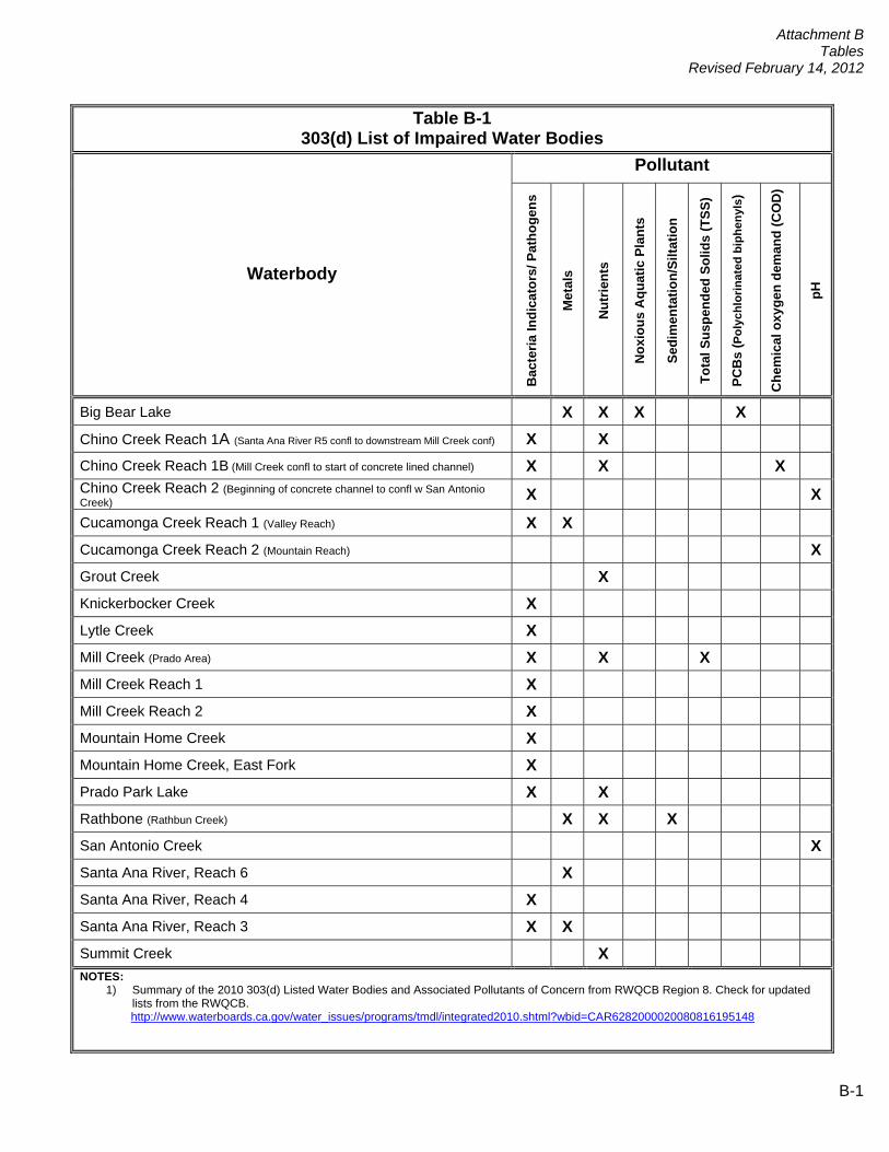
Table B-1 303(d) List of Impaired Water Bodies
Pollutant
Waterbody
Bac
teria
Indi
cato
rs/ P
atho
gens
Met
als
Nut
rient
s
Nox
ious
Aqu
atic
Pla
nts
Sedi
men
tatio
n/Si
ltatio
n
Tota
l Sus
pend
ed S
olid
s (T
SS)
PCB
s ( P
olyc
hlor
inat
ed b
iphe
nyls
)
Che
mic
al o
xyge
n de
man
d (C
OD
)
pH
Big Bear Lake X X X X Chino Creek Reach 1A (Santa Ana River R5 confl to downstream Mill Creek conf) X X Chino Creek Reach 1B (Mill Creek confl to start of concrete lined channel) X X X Chino Creek Reach 2 (Beginning of concrete channel to confl w San Antonio Creek) X X
Cucamonga Creek Reach 1 (Valley Reach) X X Cucamonga Creek Reach 2 (Mountain Reach) X Grout Creek X Knickerbocker Creek X Lytle Creek X Mill Creek (Prado Area) X X X Mill Creek Reach 1 X Mill Creek Reach 2 X Mountain Home Creek X Mountain Home Creek, East Fork X Prado Park Lake X X Rathbone (Rathbun Creek) X X X San Antonio Creek X Santa Ana River, Reach 6 X Santa Ana River, Reach 4 X Santa Ana River, Reach 3 X X Summit Creek X NOTES:
1) Summary of the 2010 303(d) Listed Water Bodies and Associated Pollutants of Concern from RWQCB Region 8. Check for updated lists from the RWQCB. http://www.waterboards.ca.gov/water_issues/programs/tmdl/integrated2010.shtml?wbid=CAR6282000020080816195148
B-1
Attachment B Tables
Revised February 14, 2012
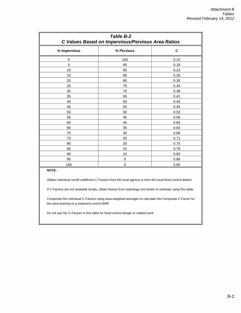
Table B-2
C Values Based on Impervious/Pervious Area Ratios
% Impervious % Pervious C
0 100 0.15 5 95 0.19
10 90 0.23 15 85 0.26 20 80 0.30 25 75 0.34 30 70 0.38 35 65 0.41 40 60 0.45 45 55 0.49 50 50 0.53 55 45 0.56 60 40 0.60 65 35 0.64 70 30 0.68 75 25 0.71 80 20 0.75 85 15 0.79 90 10 0.83 95 5 0.86 100 0 0.90
NOTE:
Obtain individual runoff coefficient C-Factors from the local agency or from the local flood control district.
If C-Factors are not available locally, obtain factors from hydrology text books or estimate using this table.
Composite the individual C-Factors using area-weighted averages to calculate the Composite C Factor for the area draining to a treatment control BMP.
Do not use the C-Factors in this table for flood control design or related work.
B-2

Attachment C Pollutants of Concern
Attachment C Pollutants of Concern
Pollutants of Concern
Bacteria and Viruses – Bacteria and Viruses are ubiquitous microorganisms that thrive under certain environmental conditions. Their proliferation is typically cause by the transport of animal or human fecal wastes from the watershed. Water, containing excessive bacteria and viruses, can alter the aquatic habitat and create a harmful environment for humans and aquatic life. Also, the decomposition of excess organic waste causes increased growth of undesirable organisms in the water.
Metals – The primary source of metal pollution in stormwater is typically commercially
available metals and metal products. Metals of concern include cadmium, chromium, copper, lead, mercury, and zinc. Lead and chromium have been used as corrosion inhibitors in primer coatings and cooling tower systems. Metals are also raw material components in non-metal products such as fuels, adhesives, paints, and other coatings. At low concentrations naturally occurring in soil, metals may not be toxic. However, at higher concentrations, certain metals can be toxic to aquatic life. Humans can be impacted from contaminated groundwater resources, and bioaccumulation of metals in fish and shellfish. Environmental concerns, regarding the potential for release of metals to the environment, have already led to restricted metal usage in certain applications (OC 2003).
Nutrients – Nutrients are inorganic substances, such as nitrogen and phosphorus.
Excessive discharge of nutrients to water bodies and streams causes eutrophication, where aquatic plants and algae growth can lead to excessive decay of organic matter in the water body, loss of oxygen in the water, release of toxins in sediment, and the eventual death of aquatic organisms. Primary sources of nutrients in urban runoff are fertilizers and eroded soils.
Pesticides -- Pesticides (including herbicides) are chemical compounds commonly used to
control nuisance growth or prevalence of organisms. Relatively low levels of the active component of pesticides can result in conditions of aquatic toxicity. Excessive or improper application of a pesticide may result in runoff containing toxic levels of its active ingredient (OC 2003).
Organic Compounds – Organic compounds are carbon-based. Commercially available or
naturally occurring organic compounds are found in pesticides, solvents, and hydrocarbons. Organic compounds can, at certain concentrations, indirectly or directly constitute a hazard to life or health. When rinsing off objects, toxic levels of solvents and cleaning compounds can be discharged to storm drains. Dirt, grease, and grime retained in the cleaning fluid or rinse water may also adsorb levels of organic compounds that are harmful or hazardous to aquatic life (OC 2003).
Sediments – Sediments are solid materials that are eroded from the land surface. Sediments can increase turbidity, clog fish gills, reduce spawning habitat, lower young aquatic organisms survival rates, smother bottom dwelling organisms, and suppress aquatic vegetation growth.
Trash and Debris – Trash (such as paper, plastic, polystyrene packing foam, and aluminum
materials) and biodegradable organic matter (such as leaves, grass cuttings, and food waste) are general waste products on the landscape. The presence of trash and debris may
C - 1
Attachment C Pollutants of Concern
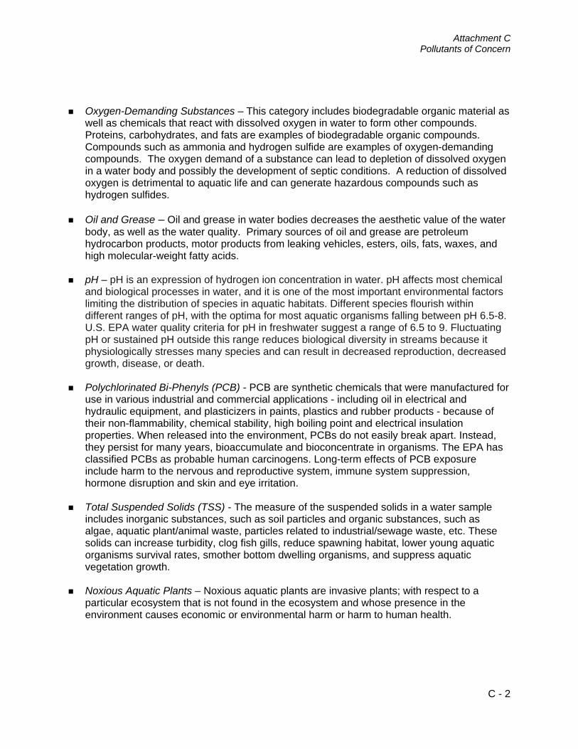
Oxygen-Demanding Substances – This category includes biodegradable organic material as
well as chemicals that react with dissolved oxygen in water to form other compounds. Proteins, carbohydrates, and fats are examples of biodegradable organic compounds. Compounds such as ammonia and hydrogen sulfide are examples of oxygen-demanding compounds. The oxygen demand of a substance can lead to depletion of dissolved oxygen in a water body and possibly the development of septic conditions. A reduction of dissolved oxygen is detrimental to aquatic life and can generate hazardous compounds such as hydrogen sulfides.
Oil and Grease – Oil and grease in water bodies decreases the aesthetic value of the water
body, as well as the water quality. Primary sources of oil and grease are petroleum hydrocarbon products, motor products from leaking vehicles, esters, oils, fats, waxes, and high molecular-weight fatty acids.
pH – pH is an expression of hydrogen ion concentration in water. pH affects most chemical and biological processes in water, and it is one of the most important environmental factors limiting the distribution of species in aquatic habitats. Different species flourish within different ranges of pH, with the optima for most aquatic organisms falling between pH 6.5-8. U.S. EPA water quality criteria for pH in freshwater suggest a range of 6.5 to 9. Fluctuating pH or sustained pH outside this range reduces biological diversity in streams because it physiologically stresses many species and can result in decreased reproduction, decreased growth, disease, or death.
Polychlorinated Bi-Phenyls (PCB) - PCB are synthetic chemicals that were manufactured for
use in various industrial and commercial applications - including oil in electrical and hydraulic equipment, and plasticizers in paints, plastics and rubber products - because of their non-flammability, chemical stability, high boiling point and electrical insulation properties. When released into the environment, PCBs do not easily break apart. Instead, they persist for many years, bioaccumulate and bioconcentrate in organisms. The EPA has classified PCBs as probable human carcinogens. Long-term effects of PCB exposure include harm to the nervous and reproductive system, immune system suppression, hormone disruption and skin and eye irritation.
Total Suspended Solids (TSS) - The measure of the suspended solids in a water sample includes inorganic substances, such as soil particles and organic substances, such as algae, aquatic plant/animal waste, particles related to industrial/sewage waste, etc. These solids can increase turbidity, clog fish gills, reduce spawning habitat, lower young aquatic organisms survival rates, smother bottom dwelling organisms, and suppress aquatic vegetation growth.
Noxious Aquatic Plants – Noxious aquatic plants are invasive plants; with respect to a
particular ecosystem that is not found in the ecosystem and whose presence in the environment causes economic or environmental harm or harm to human health.
C - 2

Attachment D
Flow- and Volume-based BMP Design Calculations
D-1
Attachment D Flow- and Volume-Based BMP Design
Calculations
Attachment D
Flow- and Volume-based BMP Design Calculations
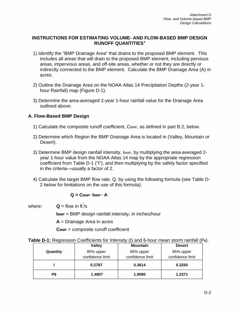
INSTRUCTIONS FOR ESTIMATING VOLUME- AND FLOW-BASED BMP DESIGN RUNOFF QUANTITIES4
1) Identify the “BMP Drainage Area” that drains to the proposed BMP element. This includes all areas that will drain to the proposed BMP element, including pervious areas, impervious areas, and off-site areas, whether or not they are directly or indirectly connected to the BMP element. Calculate the BMP Drainage Area (A) in acres.
2) Outline the Drainage Area on the NOAA Atlas 14 Precipitation Depths (2-year 1-hour Rainfall) map (Figure D-1).
3) Determine the area-averaged 2-year 1-hour rainfall value for the Drainage Area outlined above.
A. Flow-Based BMP Design
1) Calculate the composite runoff coefficient, CBMP, as defined in part B.2, below.
2) Determine which Region the BMP Drainage Area is located in (Valley, Mountain or Desert).
3) Determine BMP design rainfall intensity, IBMP, by multiplying the area-averaged 2-year 1-hour value from the NOAA Atlas 14 map by the appropriate regression coefficient from Table D-1 (“I”), and then multiplying by the safety factor specified in the criteria—usually a factor of 2.
4) Calculate the target BMP flow rate, Q, by using the following formula (see Table D-
2 below for limitations on the use of this formula):
Q = CBMP· IBMP · A
where: Q = flow in ft3
/s IBMP = BMP design rainfall intensity, in inches/hour A = Drainage Area in acres CBMP = composite runoff coefficient
Table D-1: Regression Coefficients for Intensity (I) and 6-hour mean storm rainfall (P6).
Valley Mountain Desert Quantity 85% upper 85% upper 85% upper
confidence limit confidence limit confidence limit
I 0.2787 0.3614 0.3250
P6 1.4807 1.9090 1.2371
D-2

Attachment D
Flow- and Volume-based BMP Design Calculations
Table D-2: Use of the flow-based formula for BMP Design (CASQA 2003).
Composite Runoff Coefficient, “C”
BMP Drainage Area (Acres)
0.00 to 0.25 0.26 to 0.50 0.51 to 0.75 0.76 to 1.00
0 to 25 Caution Yes Yes Yes
26 to 50 High Caution Caution Yes Yes
51 to 75 Not Recommended
High Caution Caution Yes
76 to 100 Not Recommended
High Caution Caution Yes
If the flow-based BMP formula use case, as determined by Table D-2, shows “Caution,” “High Caution,” or “Not Recommended,” considering the project’s characteristics, then he project proponent must calculate the BMP design flow using the unit hydrograph method, as specified in the most current version of the San Bernardino County Hydrology Manual, using the design storm pattern with rainfall return frequency such that the peak one hour rainfall depth equals the 85th-percentile 1-hour rainfall multiplied by two.
B. Volume-Based BMP Design
1) Calculate the “Watershed Imperviousness Ratio”, i, which is equal to the percent of impervious area in the BMP Drainage Area divided by 100.
2) Calculate the composite runoff coefficient CBMP for the Drainage Area above using the following equation:
CBMP = 0.858i3
– 0.78i2
+ 0.774i + 0.04
where: CBMP = composite runoff coefficient; and, i = watershed imperviousness ratio.
3) Determine which Region the Drainage Area is located in (Valley, Mountain or Desert).
4) Determine the area-averaged “6-hour Mean Storm Rainfall”, P6, for the Drainage Area. This is calculated by multiplying the area averaged 2-year 1-hour value by the appropriate regression coefficient from Table 1.
D-3
Attachment D
Flow- and Volume-based BMP Design Calculations
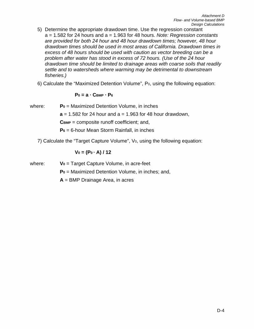
5) Determine the appropriate drawdown time. Use the regression constant a = 1.582 for 24 hours and a = 1.963 for 48 hours. Note: Regression constants are provided for both 24 hour and 48 hour drawdown times; however, 48 hour drawdown times should be used in most areas of California. Drawdown times in excess of 48 hours should be used with caution as vector breeding can be a problem after water has stood in excess of 72 hours. (Use of the 24 hour drawdown time should be limited to drainage areas with coarse soils that readily settle and to watersheds where warming may be detrimental to downstream fisheries.)
6) Calculate the “Maximized Detention Volume”, P0, using the following equation:
P0 = a · CBMP · P6
where: P0 = Maximized Detention Volume, in inches a = 1.582 for 24 hour and a = 1.963 for 48 hour drawdown, CBMP = composite runoff coefficient; and, P6 = 6-hour Mean Storm Rainfall, in inches
7) Calculate the “Target Capture Volume”, V0, using the following equation:
V0 = (P0 · A) / 12
where: V0 = Target Capture Volume, in acre-feet P0 = Maximized Detention Volume, in inches; and, A = BMP Drainage Area, in acres
D-4
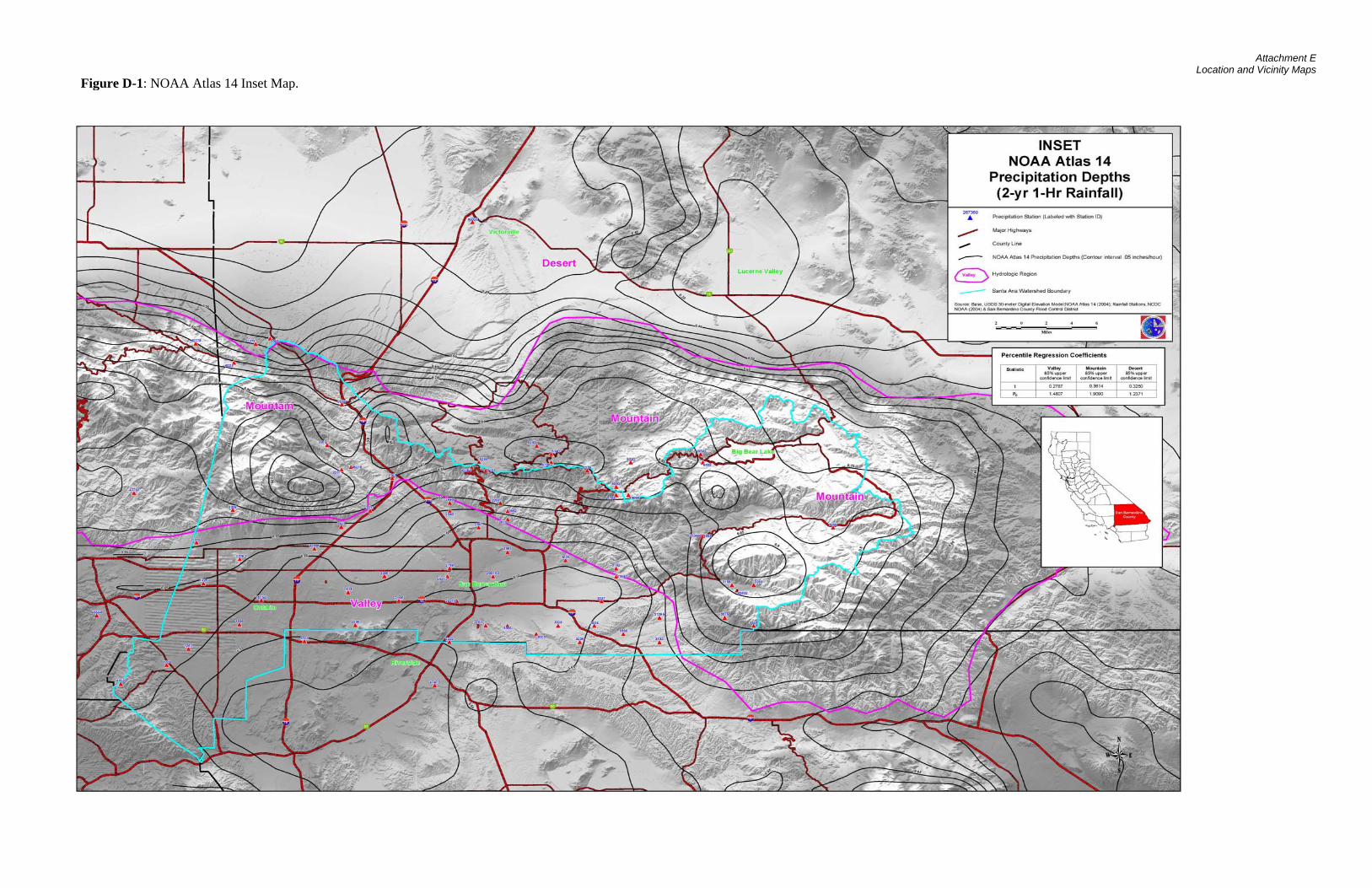
Attachment E
Location and Vicinity Maps
Figure D-1: NOAA Atlas 14 Inset Map.

Area 1
Project Data
Area Averaged 2-Year 1-Hour Rainfall From NOAA Atlas 14 = In/Hr
San Bernardino County climatic Region =
Drainage Area (A) = AcresImpervious Area = AcresPervious Area = Acres
Volume Based BMP Design RunoffCBMP = .0858i 3 – 0.78i 2 + 0.774i + 0.04P0 = a * CBMP * P6
V0 = (P0 * A) / 12Watershed Imperviousness Ratio ( i ) =
Runoff Coefficient (CBMP) =
6-Hour Mean Storm Rainfall Coefficient =6-Hour Mean Storm Rainfall (P6) = In/Hr
Watershed Imperviousness Ratio ( i ) =Draw Down Time = Hours
Regression Constant (a) =
Maximized Detention Volume (P0) = InchesTarget Capture Volume (Vo) = Acre Feet
= Cubic Feet
5/20/2012University Crossings
0.219459559
0.8720
0.55
0.81
0.7517
1.963
0.7517
0.5455
1.4807
Quantity6-hour Rainfall (P6)
MountainValley1.48070.2787
1.90900.3614
Valley
48
3.022.270.75
Regression Coefficients for Intensity (I) and 6-hour Mena Storm Rainfall
Intensity (I)
Desert1.23710.3250

Area 2
Project Data
Area Averaged 2-Year 1-Hour Rainfall From NOAA Atlas 14 = In/Hr
San Bernardino County climatic Region =
Drainage Area (A) = AcresImpervious Area = AcresPervious Area = Acres
Volume Based BMP Design RunoffCBMP = .0858i 3 – 0.78i 2 + 0.774i + 0.04P0 = a * CBMP * P6
V0 = (P0 * A) / 12Watershed Imperviousness Ratio ( i ) =
Runoff Coefficient (CBMP) =
6-Hour Mean Storm Rainfall Coefficient =6-Hour Mean Storm Rainfall (P6) = In/Hr
Watershed Imperviousness Ratio ( i ) =Draw Down Time = Hours
Regression Constant (a) =
Maximized Detention Volume (P0) = InchesTarget Capture Volume (Vo) = Acre Feet
= Cubic Feet
Valley
48
1.911.520.39
Regression Coefficients for Intensity (I) and 6-hour Mena Storm Rainfall
Intensity (I)
Desert1.23710.3250
0.5944
1.4807
Quantity6-hour Rainfall (P6)
MountainValley1.48070.2787
1.90900.3614
5/20/2012University Crossings
0.151256588
0.9502
0.55
0.81
0.7958
1.963
0.7958

Area 3
Project Data
Area Averaged 2-Year 1-Hour Rainfall From NOAA Atlas 14 = In/Hr
San Bernardino County climatic Region =
Drainage Area (A) = AcresImpervious Area = AcresPervious Area = Acres
Volume Based BMP Design RunoffCBMP = .0858i 3 – 0.78i 2 + 0.774i + 0.04P0 = a * CBMP * P6
V0 = (P0 * A) / 12Watershed Imperviousness Ratio ( i ) =
Runoff Coefficient (CBMP) =
6-Hour Mean Storm Rainfall Coefficient =6-Hour Mean Storm Rainfall (P6) = In/Hr
Watershed Imperviousness Ratio ( i ) =Draw Down Time = Hours
Regression Constant (a) =
Maximized Detention Volume (P0) = InchesTarget Capture Volume (Vo) = Acre Feet
= Cubic Feet
5/20/2012University Crossings
0.090893959
0.8726
0.55
0.81
0.7520
1.963
0.7520
0.5458
1.4807
Quantity6-hour Rainfall (P6)
MountainValley1.48070.2787
1.90900.3614
Valley
48
1.250.940.31
Regression Coefficients for Intensity (I) and 6-hour Mena Storm Rainfall
Intensity (I)
Desert1.23710.3250

Area 4
Project Data
Area Averaged 2-Year 1-Hour Rainfall From NOAA Atlas 14 = In/Hr
San Bernardino County climatic Region =
Drainage Area (A) = AcresImpervious Area = AcresPervious Area = Acres
Volume Based BMP Design RunoffCBMP = .0858i 3 – 0.78i 2 + 0.774i + 0.04P0 = a * CBMP * P6
V0 = (P0 * A) / 12Watershed Imperviousness Ratio ( i ) =
Runoff Coefficient (CBMP) =
6-Hour Mean Storm Rainfall Coefficient =6-Hour Mean Storm Rainfall (P6) = In/Hr
Watershed Imperviousness Ratio ( i ) =Draw Down Time = Hours
Regression Constant (a) =
Maximized Detention Volume (P0) = InchesTarget Capture Volume (Vo) = Acre Feet
= Cubic Feet
Valley
48
2.642.2
0.44
Regression Coefficients for Intensity (I) and 6-hour Mena Storm Rainfall
Intensity (I)
Desert1.23710.3250
0.6399
1.4807
Quantity6-hour Rainfall (P6)
MountainValley1.48070.2787
1.90900.3614
5/20/2012University Crossings
0.225049803
1.0229
0.55
0.81
0.8333
1.963
0.8333
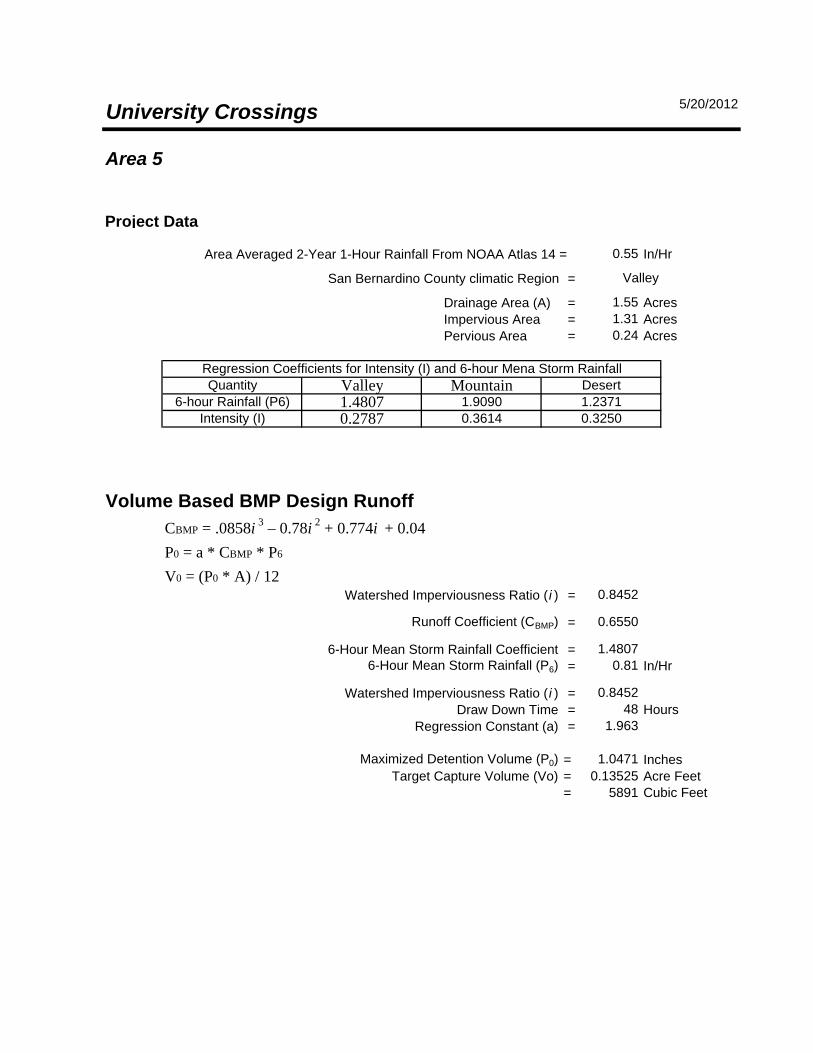
Area 5
Project Data
Area Averaged 2-Year 1-Hour Rainfall From NOAA Atlas 14 = In/Hr
San Bernardino County climatic Region =
Drainage Area (A) = AcresImpervious Area = AcresPervious Area = Acres
Volume Based BMP Design RunoffCBMP = .0858i 3 – 0.78i 2 + 0.774i + 0.04P0 = a * CBMP * P6
V0 = (P0 * A) / 12Watershed Imperviousness Ratio ( i ) =
Runoff Coefficient (CBMP) =
6-Hour Mean Storm Rainfall Coefficient =6-Hour Mean Storm Rainfall (P6) = In/Hr
Watershed Imperviousness Ratio ( i ) =Draw Down Time = Hours
Regression Constant (a) =
Maximized Detention Volume (P0) = InchesTarget Capture Volume (Vo) = Acre Feet
= Cubic Feet
5/20/2012University Crossings
0.135255891
1.0471
0.55
0.81
0.8452
1.963
0.8452
0.6550
1.4807
Quantity6-hour Rainfall (P6)
MountainValley1.48070.2787
1.90900.3614
Valley
48
1.551.310.24
Regression Coefficients for Intensity (I) and 6-hour Mena Storm Rainfall
Intensity (I)
Desert1.23710.3250
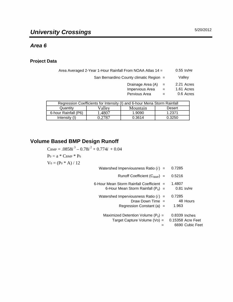
Area 6
Project Data
Area Averaged 2-Year 1-Hour Rainfall From NOAA Atlas 14 = In/Hr
San Bernardino County climatic Region =
Drainage Area (A) = AcresImpervious Area = AcresPervious Area = Acres
Volume Based BMP Design RunoffCBMP = .0858i 3 – 0.78i 2 + 0.774i + 0.04P0 = a * CBMP * P6
V0 = (P0 * A) / 12Watershed Imperviousness Ratio ( i ) =
Runoff Coefficient (CBMP) =
6-Hour Mean Storm Rainfall Coefficient =6-Hour Mean Storm Rainfall (P6) = In/Hr
Watershed Imperviousness Ratio ( i ) =Draw Down Time = Hours
Regression Constant (a) =
Maximized Detention Volume (P0) = InchesTarget Capture Volume (Vo) = Acre Feet
= Cubic Feet
Valley
48
2.211.610.6
Regression Coefficients for Intensity (I) and 6-hour Mena Storm Rainfall
Intensity (I)
Desert1.23710.3250
0.5216
1.4807
Quantity6-hour Rainfall (P6)
MountainValley1.48070.2787
1.90900.3614
5/20/2012University Crossings
0.153586690
0.8339
0.55
0.81
0.7285
1.963
0.7285
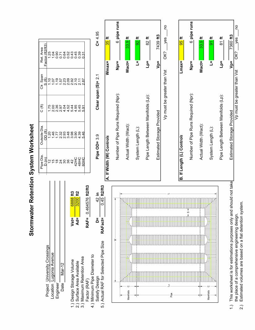
Sto
rmw
ate
r R
ete
nti
on
Sy
ste
m W
ork
sh
ee
t
Project University Crossings
Location Lugonia Avenue
Engineer
Date
Mar-12
1.)Design Storage Volume
Vs
t=6888
ft3
2.)Surface Area Available
Ad
=3200
ft2
3.)Maximum Retention Area
Factor (RAF)
RA
F=0.464576
ft2
/ft3
4.)Minimum Pipe Diameter to
Satisfy Design
D=
42
inP
ipe
OD
=3.9
Cle
ar
sp
an
(S
)=2.1
C=4.95
5.)Actual RAF for Selected Pipe Size
RA
Fa
ct=
0.45
ft2
/ft3
A.
If W
idth
(W
) C
on
tro
lsW
ma
x=
35
ft
Number of Pipe Runs Required (Npr):
Np
r=6
pip
e r
un
s
Actual Width (Wact):
Wa
ct=
33.9
ft
System Length (L):
L=
92
ft
Pipe Length Between Manifolds (Lp):
Lp
=82
ft
Estimated Storage Provided
Vp
=7439
ft3
Vp must be greater than Vst
OK? ___yes ___no
B.
If L
en
gth
(L
) C
on
tro
lsL
ma
x=
95
ft
Number of Pipe Runs Required (Npr):
Np
r=6
pip
e r
un
s
Actual Width (Wact):
Wa
ct=
33.9
ft
System Length (L):
L=
91
ft
Pipe Length Between Manifolds (Lp):
Lp
=81
ft
1.)This worksheet is for estimations purposes only and should not take
Estimated Storage Provided
Vp
=7360
ft3
the place of a comprehensive engineering design.
Vp must be greater than Vst
OK? ___yes ___no
2.)Estimated volumes are based on a flat detention system.
W
LLP
S
Manifolds
Pipe
Manifolds
C C
Pipe Dia.
D (in)
Outside Dia.
OD (ft)
C (ft)
Clr. Span
S (ft)
Ret. Area
Factor (ft2/ft3)
12151824303642
42HC
48HC
60HC
1.20
1.46
1.77
2.32
2.93
3.48
3.98
3.90
4.39
5.46
1.75
2.00
2.36
2.97
4.04
4.52
5.44
4.95
5.45
5.91
1.10
1.07
1.19
1.57
2.23
2.09
2.92
2.10
2.11
2.87
1.25
1.04
0.90
0.71
0.64
0.52
0.43
0.45
0.39
0.31
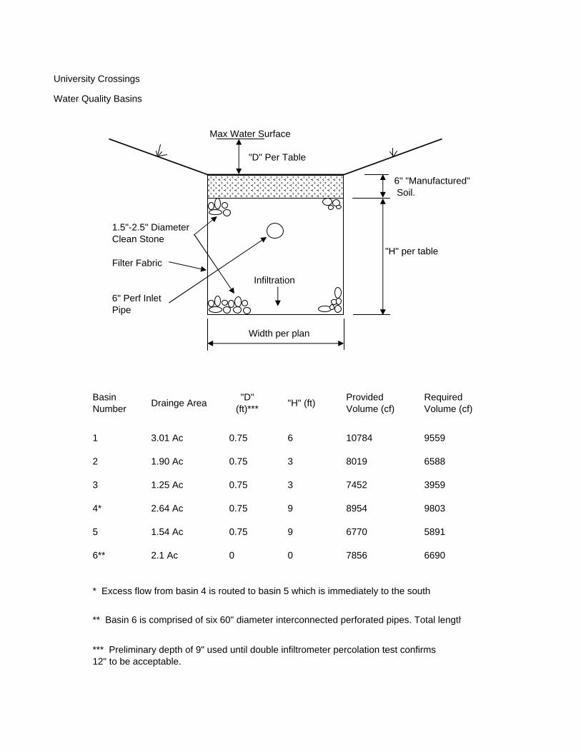
University Crossings
Water Quality Basins
Max Water Surface
"D" Per Table
"H" per tableFilter Fabric
6" Perf InletPipe
Width per plan
* Excess flow from basin 4 is routed to basin 5 which is immediately to the south
*** Preliminary depth of 9" used until double infiltrometer percolation test confirms12" to be acceptable.
** Basin 6 is comprised of six 60" diameter interconnected perforated pipes. Total length
5891
6690
9803
0
8954
6770
7856
9
9
6588
3959
3 8019
74523
0.75
0.75
0.75
0.75
02.1 Ac
Basin Number
1
2
3
4*
5
6**
1.90 Ac
1.25 Ac
2.64 Ac
1.54 Ac
Required Volume (cf)
3.01 Ac 10784 9559
"D" (ft)***
0.75
"H" (ft)
6
1.5"-2.5" Diameter Clean Stone
Drainge Area Provided Volume (cf)
6" "Manufactured" Soil.
Infiltration
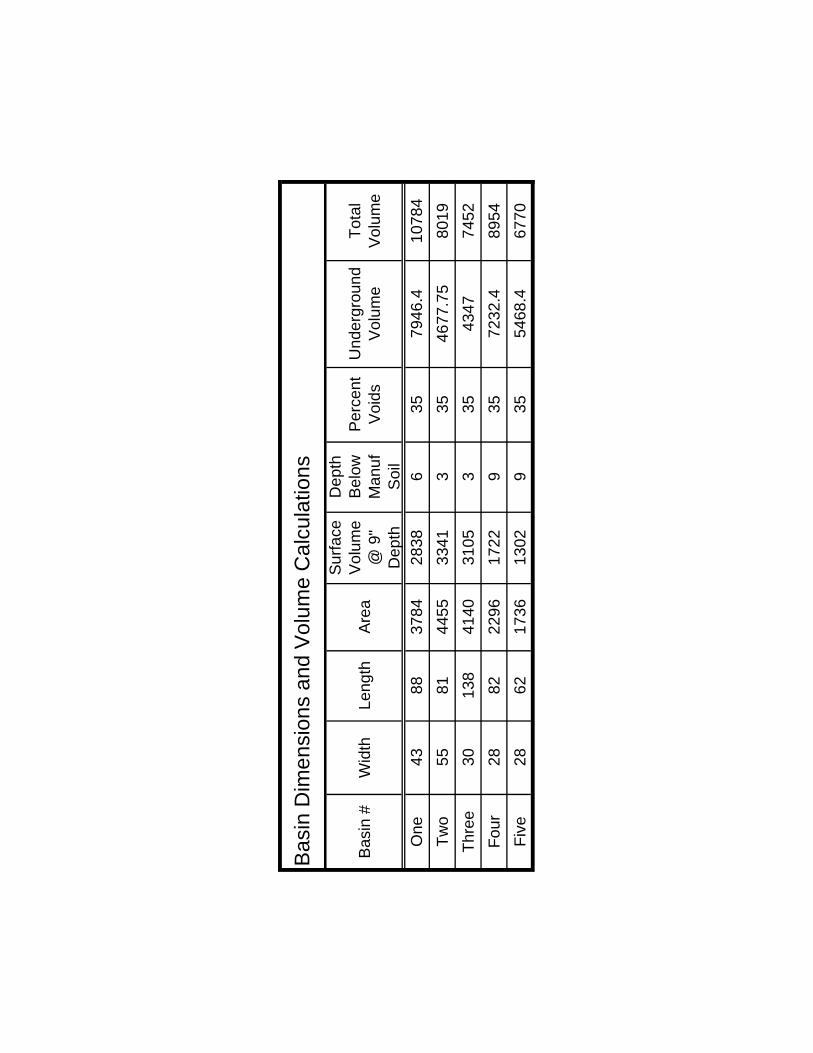
Bas
in #
Wid
th
Leng
thA
rea
Sur
face
V
olum
e @
9"
Dep
th
Dep
th
Bel
ow
Man
uf
Soi
l
Per
cent
V
oids
Und
ergr
ound
V
olum
eTo
tal
Vol
ume
One
4388
3784
2838
635
7946
.410
784
Two
5581
4455
3341
335
4677
.75
8019
Thre
e30
138
4140
3105
335
4347
7452
Four
2882
2296
1722
935
7232
.489
54Fi
ve28
6217
3613
029
3554
68.4
6770
Bas
in D
imen
sion
s an
d V
olum
e C
alcu
latio
ns
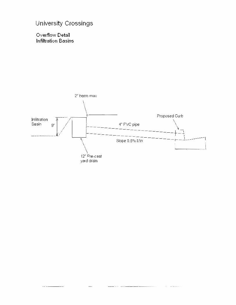

Attachment E
Location and Vicinity Maps
Attachment E Location and Vicinity Map
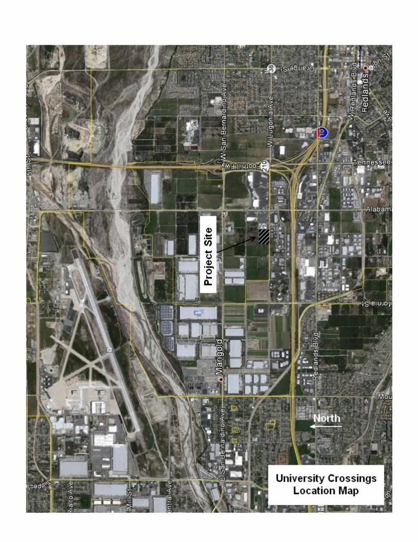
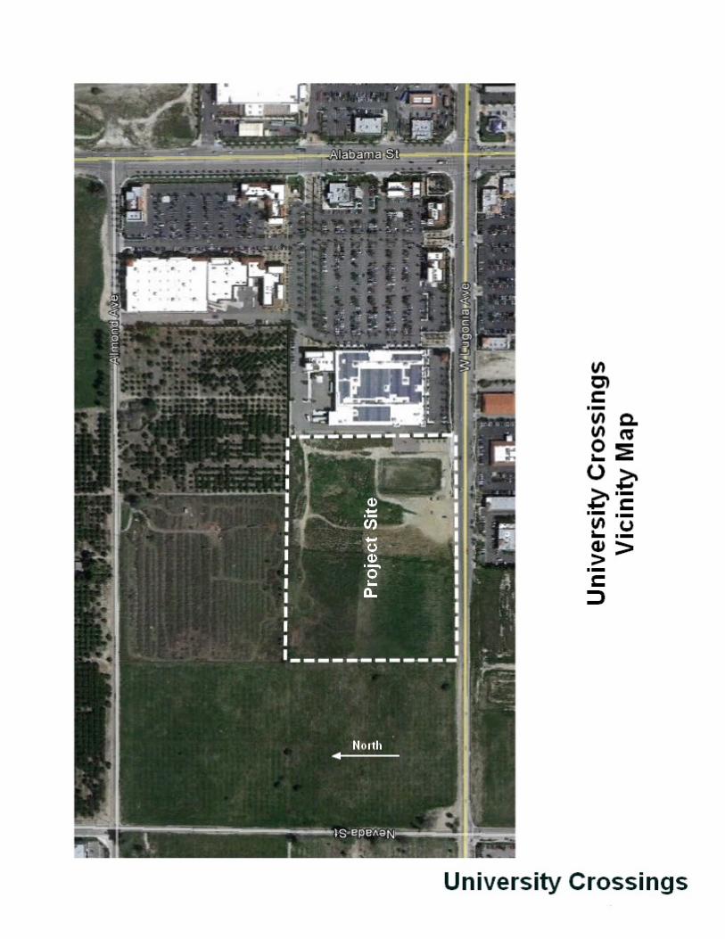

Attachment F Educational Materials
June 09, 2005 F-1
Attachment F Drainage and Improvement Plans

Attachment G Educational Materials
June 09, 2005 G-1
Attachment G BMP Sheets
Alternative Building Materials SD-21
January 2003 California Stormwater BMP Handbook 1 of 3
New Development and Redevelopment
www.cabmphandbook.com
Description
Alternative building materials are selected instead of conventional materials for new construction and renovation. These materials reduce potential sources of pollutants in stormwater runoff by eliminating compounds that can leach into runoff, reducing the need for pesticide application, reducing the need for painting and other maintenance, or by reducing the volume of runoff.
Approach
Alternative building materials are available for use as lumber for decking, roofing materials, home siding, and paving for driveways, decks, and sidewalks.
Suitable Applications
Appropriate applications include residential, commercial and industrial areas planned for development or redevelopment.
Design Considerations
Designing New Installations
Decking
One of the most common materials for construction of decks and other outdoor construction has traditionally been pressure treated wood, which is now being phased out. The standard treatment is called CCA, for chromated copper arsenate. The key ingredients are arsenic (which kills termites, carpenter ants and other insects), copper (which kills the fungi that cause wood to rot) and chromium (which reacts with the other ingredients to bind them to the wood). The amount of arsenic is far from trivial. A deck just 8 feet x 10 feet contains more than 1 1/3 pounds of this highly potent poison. Replacement materials include a new type of pressure treated wood, plastic and composite lumber.
Design Objectives
Z Maximize Infiltration
Z Provide Retention
Z Source Control
Minimize Impervious Land Coverage
Prohibit Dumping of Improper Materials
Contain Pollutant
Collect and Convey
SD-21 Alternative Building Materials
2 of 3 California Stormwater BMP Handbook January 2003
New Development and Redevelopment
www.cabmphandbook.com
There are currently over 20 products in the market consisting of plastic or plastic-wood composites. Plastic lumber is made from 100% recycled plastic, # 2 HDPE and polyethylene plastic milk jugs and soap bottles. Plastic-wood composites are a combination of plastic and wood fibers or sawdust. These materials are a long lasting exterior weather, insect, and chemical resistant wood lumber replacement for non structural applications. Use it for decks, docks, raised garden beds and planter boxes, pallets, hand railings, outdoor furniture, animal pens, boat decks, etc.
New pressure treated wood uses a much safer recipe, ACQ, which stands for ammoniacal copper quartenary. It contains no arsenic and no chromium. Yet the American Wood Preservers Association has found it to be just as effective as the standard formula. ACQ is common in Japan and Europe.
Roofing
Several studies have indicated that metal used as roofing material, flashing, or gutters can leach metals into the environment. The leaching occurs because rainfall is slightly acidic and slowly dissolved the exposed metals. Common traditional applications include copper sheathing and galvanized (zinc) gutters.
Coated metal products are available for both roofing and gutter applications. These products eliminate contact of bare metal with rainfall, eliminating one source of metals in runoff. There are also roofing materials made of recycled rubber and plastic that resemble traditional materials.
A less traditional approach is the use of green roofs. These roofs are not just green, they're alive. Planted with grasses and succulents, low- profile green roofs reduce the urban heat island effect, stormwater runoff, and cooling costs, while providing wildlife habitat and a connection to nature for building occupants. These roofs are widely used on industrial facilities in Europe and have been established as experimental installations in several locations in the US, including Portland, Oregon. Their feasibility is questionable in areas of California with prolonged, dry, hot weather.
Paved Areas
Traditionally, concrete is used for construction of patios, sidewalks, and driveways. Although it is non-toxic, these paved areas reduce stormwater infiltration and increase the volume and rate of runoff. This increase in the amount of runoff is the leading cause of stream channel degradation in urban areas.
There are a number of alternative materials that can be used in these applications, including porous concrete and asphalt, modular blocks, and crushed granite. These materials, especially modular paving blocks, are widely available and a well established method to reduce stormwater runoff.
Building Siding
Wood siding is commonly used on the exterior of residential construction. This material weathers fairly rapidly and requires repeated painting to prevent rotting. Alternative “new” products for this application include cement-fiber and vinyl. Cement-fiber siding is a masonry product made from Portland cement, sand, and cellulose and will not burn, cup, swell, or shrink.
Alternative Building Materials SD-21
January 2003 California Stormwater BMP Handbook 3 of 3
New Development and Redevelopment
www.cabmphandbook.com
Pesticide Reduction A common use of powerful pesticides is for the control of termites. Chlordane was used for many years for this purpose and is now found in urban streams and lakes nationwide. There are a number of physical barriers that can be installed during construction to help reduce the use of pesticides.
Sand barriers for subterranean termites are a physical deterrent because the termites cannot tunnel through it. Sand barriers can be applied in crawl spaces under pier and beam foundations, under slab foundations, and between the foundation and concrete porches, terraces, patios and steps. Other possible locations include under fence posts, underground electrical cables, water and gas lines, telephone and electrical poles, inside hollow tile cells and against retaining walls.
Metal termite shields are physical barriers to termites which prevent them from building invisible tunnels. In reality, metal shields function as a helpful termite detection device, forcing them to build tunnels on the outside of the shields which are easily seen. Metal termite shields also help prevent dampness from wicking to adjoining wood members which can result in rot, thus making the material more attractive to termites and other pests. Metal flashing and metal plates can also be used as a barrier between piers and beams of structures such as decks, which are particularly vulnerable to termite attack.
Redeveloping Existing Installations
Various jurisdictional stormwater management and mitigation plans (SUSMP, WQMP, etc.) define “redevelopment” in terms of amounts of additional impervious area, increases in gross floor area and/or exterior construction, and land disturbing activities with structural or impervious surfaces. The definition of “redevelopment” must be consulted to determine whether or not the requirements for new development apply to areas intended for redevelopment. If the definition applies, the steps outlined under “designing new installations” above should be followed.
Other Resources
There are no good, independent, comprehensive sources of information on alternative building materials for use in minimizing the impacts of stormwater runoff. Most websites or other references to “green” or “alternative” building materials focus on indoor applications, such as formaldehyde free plywood and low VOC paints, carpets, and pads. Some supplemental information on alternative materials is available from the manufacturers.
Fires are a source of concern in many areas of California. Information on the flammability of alternative decking materials is available from the University of California Forest Product Laboratory (UCFPL) website at: http://www.ucfpl.ucop.edu/WDDeckIntro.htm
Storm Drain Signage SD-13
January 2003 California Stormwater BMP Handbook 1 of 2
New Development and Redevelopment
www.cabmphandbooks.com
Description
Waste materials dumped into storm drain inlets can have severe impacts on receiving and ground waters. Posting notices regarding discharge prohibitions at storm drain inlets can prevent waste dumping. Storm drain signs and stencils are highly visible source controls that are typically placed directly adjacent to storm drain inlets.
Approach
The stencil or affixed sign contains a brief statement that prohibits dumping of improper materials into the urban runoff conveyance system. Storm drain messages have become a popular method of alerting the public about the effects of and the prohibitions against waste disposal.
Suitable Applications
Stencils and signs alert the public to the destination of pollutants discharged to the storm drain. Signs are appropriate in residential, commercial, and industrial areas, as well as any other area where contributions or dumping to storm drains is likely.
Design Considerations
Storm drain message markers or placards are recommended at all storm drain inlets within the boundary of a development project. The marker should be placed in clear sight facing toward anyone approaching the inlet from either side. All storm drain inlet locations should be identified on the development site map.
Designing New Installations
The following methods should be considered for inclusion in the project design and show on project plans:
Provide stenciling or labeling of all storm drain inlets and catch basins, constructed or modified, within the project area with prohibitive language. Examples include “NO DUMPING
Design Objectives
Maximize Infiltration
Provide Retention
Slow Runoff
Minimize Impervious Land Coverage
Z Prohibit Dumping of Improper Materials
Contain Pollutants
Collect and Convey
SD-13 Storm Drain Signage
2 of 2 California Stormwater BMP Handbook January 2003
New Development and Redevelopment
www.cabmphandbooks.com
– DRAINS TO OCEAN” and/or other graphical icons to discourage illegal dumping.
Post signs with prohibitive language and/or graphical icons, which prohibit illegal dumping at public access points along channels and creeks within the project area.
Note - Some local agencies have approved specific signage and/or storm drain message placards for use. Consult local agency stormwater staff to determine specific requirements for placard types and methods of application.
Redeveloping Existing Installations
Various jurisdictional stormwater management and mitigation plans (SUSMP, WQMP, etc.) define “redevelopment” in terms of amounts of additional impervious area, increases in gross floor area and/or exterior construction, and land disturbing activities with structural or impervious surfaces. If the project meets the definition of “redevelopment”, then the requirements stated under “ designing new installations” above should be included in all project design plans.
Additional Information
Maintenance Considerations
Legibility of markers and signs should be maintained. If required by the agency with jurisdiction over the project, the owner/operator or homeowner’s association should enter into a maintenance agreement with the agency or record a deed restriction upon the property title to maintain the legibility of placards or signs.
Placement
Signage on top of curbs tends to weather and fade.
Signage on face of curbs tends to be worn by contact with vehicle tires and sweeper brooms.
Supplemental Information
Examples
Most MS4 programs have storm drain signage programs. Some MS4 programs will provide stencils, or arrange for volunteers to stencil storm drains as part of their outreach program.
Other Resources
A Manual for the Standard Urban Stormwater Mitigation Plan (SUSMP), Los Angeles County Department of Public Works, May 2002.
Model Standard Urban Storm Water Mitigation Plan (SUSMP) for San Diego County, Port of San Diego, and Cities in San Diego County, February 14, 2002.
Model Water Quality Management Plan (WQMP) for County of Orange, Orange County Flood Control District, and the Incorporated Cities of Orange County, Draft February 2003.
Ventura Countywide Technical Guidance Manual for Stormwater Quality Control Measures, July 2002.
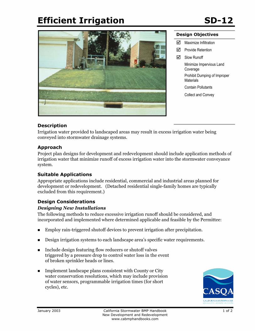
Efficient Irrigation SD-12
January 2003 California Stormwater BMP Handbook 1 of 2
New Development and Redevelopment
www.cabmphandbooks.com
Description
Irrigation water provided to landscaped areas may result in excess irrigation water being conveyed into stormwater drainage systems.
Approach
Project plan designs for development and redevelopment should include application methods of irrigation water that minimize runoff of excess irrigation water into the stormwater conveyance system.
Suitable Applications
Appropriate applications include residential, commercial and industrial areas planned for development or redevelopment. (Detached residential single-family homes are typically excluded from this requirement.)
Design Considerations
Designing New Installations
The following methods to reduce excessive irrigation runoff should be considered, and incorporated and implemented where determined applicable and feasible by the Permittee:
Employ rain-triggered shutoff devices to prevent irrigation after precipitation.
Design irrigation systems to each landscape area’s specific water requirements.
Include design featuring flow reducers or shutoff valves triggered by a pressure drop to control water loss in the event of broken sprinkler heads or lines.
Implement landscape plans consistent with County or City water conservation resolutions, which may include provision of water sensors, programmable irrigation times (for short cycles), etc.
Design Objectives
Z Maximize Infiltration
Z Provide Retention
Z Slow Runoff
Minimize Impervious Land Coverage
Prohibit Dumping of Improper Materials
Contain Pollutants
Collect and Convey

SD-12 Efficient Irrigation
2 of 2 California Stormwater BMP Handbook January 2003
New Development and Redevelopment
www.cabmphandbooks.com
Design timing and application methods of irrigation water to minimize the runoff of excess irrigation water into the storm water drainage system.
Group plants with similar water requirements in order to reduce excess irrigation runoff and promote surface filtration. Choose plants with low irrigation requirements (for example, native or drought tolerant species). Consider design features such as:
- Using mulches (such as wood chips or bar) in planter areas without ground cover to minimize sediment in runoff
- Installing appropriate plant materials for the location, in accordance with amount of sunlight and climate, and use native plant materials where possible and/or as recommended by the landscape architect
- Leaving a vegetative barrier along the property boundary and interior watercourses, to act as a pollutant filter, where appropriate and feasible
- Choosing plants that minimize or eliminate the use of fertilizer or pesticides to sustain growth
Employ other comparable, equally effective methods to reduce irrigation water runoff.
Redeveloping Existing Installations
Various jurisdictional stormwater management and mitigation plans (SUSMP, WQMP, etc.) define “redevelopment” in terms of amounts of additional impervious area, increases in gross floor area and/or exterior construction, and land disturbing activities with structural or impervious surfaces. The definition of “ redevelopment” must be consulted to determine whether or not the requirements for new development apply to areas intended for redevelopment. If the definition applies, the steps outlined under “designing new installations” above should be followed.
Other Resources
A Manual for the Standard Urban Stormwater Mitigation Plan (SUSMP), Los Angeles County Department of Public Works, May 2002.
Model Standard Urban Storm Water Mitigation Plan (SUSMP) for San Diego County, Port of San Diego, and Cities in San Diego County, February 14, 2002.
Model Water Quality Management Plan (WQMP) for County of Orange, Orange County Flood Control District, and the Incorporated Cities of Orange County, Draft February 2003.
Ventura Countywide Technical Guidance Manual for Stormwater Quality Control Measures, July 2002.
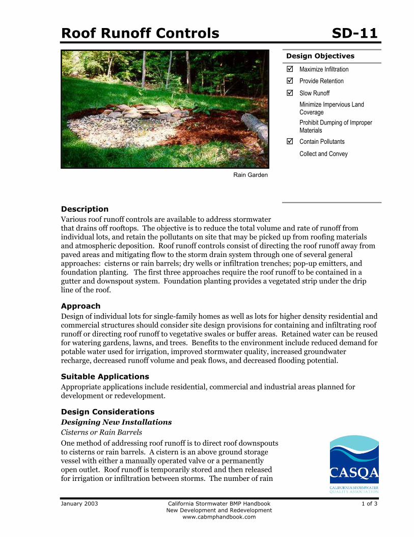
Roof Runoff Controls SD-11
January 2003 California Stormwater BMP Handbook 1 of 3
New Development and Redevelopment
www.cabmphandbook.com
Description
Various roof runoff controls are available to address stormwater that drains off rooftops. The objective is to reduce the total volume and rate of runoff from individual lots, and retain the pollutants on site that may be picked up from roofing materials and atmospheric deposition. Roof runoff controls consist of directing the roof runoff away from paved areas and mitigating flow to the storm drain system through one of several general approaches: cisterns or rain barrels; dry wells or infiltration trenches; pop-up emitters, and foundation planting. The first three approaches require the roof runoff to be contained in a gutter and downspout system. Foundation planting provides a vegetated strip under the drip line of the roof.
Approach
Design of individual lots for single-family homes as well as lots for higher density residential and commercial structures should consider site design provisions for containing and infiltrating roof runoff or directing roof runoff to vegetative swales or buffer areas. Retained water can be reused for watering gardens, lawns, and trees. Benefits to the environment include reduced demand for potable water used for irrigation, improved stormwater quality, increased groundwater recharge, decreased runoff volume and peak flows, and decreased flooding potential.
Suitable Applications
Appropriate applications include residential, commercial and industrial areas planned for development or redevelopment.
Design Considerations
Designing New Installations
Cisterns or Rain Barrels
One method of addressing roof runoff is to direct roof downspouts to cisterns or rain barrels. A cistern is an above ground storage vessel with either a manually operated valve or a permanently open outlet. Roof runoff is temporarily stored and then released for irrigation or infiltration between storms. The number of rain
Design Objectives
Z Maximize Infiltration
Z Provide Retention
Z Slow Runoff
Minimize Impervious Land Coverage
Prohibit Dumping of Improper Materials
Z Contain Pollutants
Collect and Convey
Rain Garden
SD-11 Roof Runoff Controls
2 of 3 California Stormwater BMP Handbook January 2003
New Development and Redevelopment
www.cabmphandbook.com
barrels needed is a function of the rooftop area. Some low impact developers recommend that every house have at least 2 rain barrels, with a minimum storage capacity of 1000 liters. Roof barrels serve several purposes including mitigating the first flush from the roof which has a high volume, amount of contaminants, and thermal load. Several types of rain barrels are commercially available. Consideration must be given to selecting rain barrels that are vector proof and childproof. In addition, some barrels are designed with a bypass valve that filters out grit and other contaminants and routes overflow to a soak-away pit or rain garden.
If the cistern has an operable valve, the valve can be closed to store stormwater for irrigation or infiltration between storms. This system requires continual monitoring by the resident or grounds crews, but provides greater flexibility in water storage and metering. If a cistern is provided with an operable valve and water is stored inside for long periods, the cistern must be covered to prevent mosquitoes from breeding.
A cistern system with a permanently open outlet can also provide for metering stormwater runoff. If the cistern outlet is significantly smaller than the size of the downspout inlet (say ¼ to ½ inch diameter), runoff will build up inside the cistern during storms, and will empty out slowly after peak intensities subside. This is a feasible way to mitigate the peak flow increases caused by rooftop impervious land coverage, especially for the frequent, small storms.
Dry wells and Infiltration Trenches
Roof downspouts can be directed to dry wells or infiltration trenches. A dry well is constructed by excavating a hole in the ground and filling it with an open graded aggregate, and allowing the water to fill the dry well and infiltrate after the storm event. An underground connection from the downspout conveys water into the dry well, allowing it to be stored in the voids. To minimize sedimentation from lateral soil movement, the sides and top of the stone storage matrix can be wrapped in a permeable filter fabric, though the bottom may remain open. A perforated observation pipe can be inserted vertically into the dry well to allow for inspection and maintenance.
In practice, dry wells receiving runoff from single roof downspouts have been successful over long periods because they contain very little sediment. They must be sized according to the amount of rooftop runoff received, but are typically 4 to 5 feet square, and 2 to 3 feet deep, with a minimum of 1-foot soil cover over the top (maximum depth of 10 feet).
To protect the foundation, dry wells must be set away from the building at least 10 feet. They must be installed in solids that accommodate infiltration. In poorly drained soils, dry wells have very limited feasibility.
Infiltration trenches function in a similar manner and would be particularly effective for larger roof areas. An infiltration trench is a long, narrow, rock-filled trench with no outlet that receives stormwater runoff. These are described under Treatment Controls.
Pop-up Drainage Emitter
Roof downspouts can be directed to an underground pipe that daylights some distance from the building foundation, releasing the roof runoff through a pop-up emitter. Similar to a pop-up irrigation head, the emitter only opens when there is flow from the roof. The emitter remains flush to the ground during dry periods, for ease of lawn or landscape maintenance.
Roof Runoff Controls SD-11
January 2003 California Stormwater BMP Handbook 3 of 3
New Development and Redevelopment
www.cabmphandbook.com
Foundation Planting
Landscape planting can be provided around the base to allow increased opportunities for stormwater infiltration and protect the soil from erosion caused by concentrated sheet flow coming off the roof. Foundation plantings can reduce the physical impact of water on the soil and provide a subsurface matrix of roots that encourage infiltration. These plantings must be sturdy enough to tolerate the heavy runoff sheet flows, and periodic soil saturation.
Redeveloping Existing Installations
Various jurisdictional stormwater management and mitigation plans (SUSMP, WQMP, etc.) define “redevelopment” in terms of amounts of additional impervious area, increases in gross floor area and/or exterior construction, and land disturbing activities with structural or impervious surfaces. The definition of “ redevelopment” must be consulted to determine whether or not the requirements for new development apply to areas intended for redevelopment. If the definition applies, the steps outlined under “designing new installations” above should be followed.
Supplemental Information
Examples
City of Ottawa’s Water Links Surface –Water Quality Protection Program
City of Toronto Downspout Disconnection Program
City of Boston, MA, Rain Barrel Demonstration Program
Other Resources
Hager, Marty Catherine, Stormwater, “Low-Impact Development”, January/February 2003. www.stormh2o.com
Low Impact Urban Design Tools, Low Impact Development Design Center, Beltsville, MD. www.lid-stormwater.net
Start at the Source, Bay Area Stormwater Management Agencies Association, 1999 Edition

Site Design & Landscape Planning SD-10
January 2003 California Stormwater BMP Handbook 1 of 4
New Development and Redevelopment
www.cabmphandbooks.com
Description
Each project site possesses unique topographic, hydrologic, and vegetative features, some of which are more suitable for development than others. Integrating and incorporating appropriate landscape planning methodologies into the project design is the most effective action that can be done to minimize surface and groundwater contamination from stormwater.
Approach
Landscape planning should couple consideration of land suitability for urban uses with consideration of community goals and projected growth. Project plan designs should conserve natural areas to the extent possible, maximize natural water storage and infiltration opportunities, and protect slopes and channels.
Suitable Applications
Appropriate applications include residential, commercial and industrial areas planned for development or redevelopment.
Design Considerations
Design requirements for site design and landscapes planning should conform to applicable standards and specifications of agencies with jurisdiction and be consistent with applicable General Plan and Local Area Plan policies.
Design Objectives
Z Maximize Infiltration
Z Provide Retention
Z Slow Runoff
Z Minimize Impervious Land Coverage
Prohibit Dumping of Improper Materials
Contain Pollutants
Collect and Convey
SD-10 Site Design & Landscape Planning
2 of 4 California Stormwater BMP Handbook January 2003
New Development and Redevelopment
www.cabmphandbooks.com
Designing New Installations
Begin the development of a plan for the landscape unit with attention to the following general principles:
Formulate the plan on the basis of clearly articulated community goals. Carefully identify conflicts and choices between retaining and protecting desired resources and community growth.
Map and assess land suitability for urban uses. Include the following landscape features in the assessment: wooded land, open unwooded land, steep slopes, erosion-prone soils, foundation suitability, soil suitability for waste disposal, aquifers, aquifer recharge areas, wetlands, floodplains, surface waters, agricultural lands, and various categories of urban land use. When appropriate, the assessment can highlight outstanding local or regional resources that the community determines should be protected (e.g., a scenic area, recreational area, threatened species habitat, farmland, fish run). Mapping and assessment should recognize not only these resources but also additional areas needed for their sustenance.
Project plan designs should conserve natural areas to the extent possible, maximize natural water storage and infiltration opportunities, and protect slopes and channels.
Conserve Natural Areas during Landscape Planning
If applicable, the following items are required and must be implemented in the site layout during the subdivision design and approval process, consistent with applicable General Plan and Local Area Plan policies:
Cluster development on least-sensitive portions of a site while leaving the remaining land in a natural undisturbed condition.
Limit clearing and grading of native vegetation at a site to the minimum amount needed to build lots, allow access, and provide fire protection.
Maximize trees and other vegetation at each site by planting additional vegetation, clustering tree areas, and promoting the use of native and/or drought tolerant plants.
Promote natural vegetation by using parking lot islands and other landscaped areas.
Preserve riparian areas and wetlands.
Maximize Natural Water Storage and Infiltration Opportunities Within the Landscape Unit
Promote the conservation of forest cover. Building on land that is already deforested affects basin hydrology to a lesser extent than converting forested land. Loss of forest cover reduces interception storage, detention in the organic forest floor layer, and water losses by evapotranspiration, resulting in large peak runoff increases and either their negative effects or the expense of countering them with structural solutions.
Maintain natural storage reservoirs and drainage corridors, including depressions, areas of permeable soils, swales, and intermittent streams. Develop and implement policies and

Site Design & Landscape Planning SD-10
January 2003 California Stormwater BMP Handbook 3 of 4
New Development and Redevelopment
www.cabmphandbooks.com
regulations to discourage the clearing, filling, and channelization of these features. Utilize them in drainage networks in preference to pipes, culverts, and engineered ditches.
Evaluating infiltration opportunities by referring to the stormwater management manual for the jurisdiction and pay particular attention to the selection criteria for avoiding groundwater contamination, poor soils, and hydrogeological conditions that cause these facilities to fail. If necessary, locate developments with large amounts of impervious surfaces or a potential to produce relatively contaminated runoff away from groundwater recharge areas.
Protection of Slopes and Channels during Landscape Design
Convey runoff safely from the tops of slopes.
Avoid disturbing steep or unstable slopes.
Avoid disturbing natural channels.
Stabilize disturbed slopes as quickly as possible.
Vegetate slopes with native or drought tolerant vegetation.
Control and treat flows in landscaping and/or other controls prior to reaching existing natural drainage systems.
Stabilize temporary and permanent channel crossings as quickly as possible, and ensure that increases in run-off velocity and frequency caused by the project do not erode the channel.
Install energy dissipaters, such as riprap, at the outlets of new storm drains, culverts, conduits, or channels that enter unlined channels in accordance with applicable specifications to minimize erosion. Energy dissipaters shall be installed in such a way as to minimize impacts to receiving waters.
Line on-site conveyance channels where appropriate, to reduce erosion caused by increased flow velocity due to increases in tributary impervious area. The first choice for linings should be grass or some other vegetative surface, since these materials not only reduce runoff velocities, but also provide water quality benefits from filtration and infiltration. If velocities in the channel are high enough to erode grass or other vegetative linings, riprap, concrete, soil cement, or geo-grid stabilization are other alternatives.
Consider other design principles that are comparable and equally effective.
Redeveloping Existing Installations
Various jurisdictional stormwater management and mitigation plans (SUSMP, WQMP, etc.) define “redevelopment” in terms of amounts of additional impervious area, increases in gross floor area and/or exterior construction, and land disturbing activities with structural or impervious surfaces. The definition of “ redevelopment” must be consulted to determine whether or not the requirements for new development apply to areas intended for redevelopment. If the definition applies, the steps outlined under “designing new installations” above should be followed.
SD-10 Site Design & Landscape Planning
4 of 4 California Stormwater BMP Handbook January 2003
New Development and Redevelopment
www.cabmphandbooks.com
Redevelopment may present significant opportunity to add features which had not previously been implemented. Examples include incorporation of depressions, areas of permeable soils, and swales in newly redeveloped areas. While some site constraints may exist due to the status of already existing infrastructure, opportunities should not be missed to maximize infiltration, slow runoff, reduce impervious areas, disconnect directly connected impervious areas.
Other Resources
A Manual for the Standard Urban Stormwater Mitigation Plan (SUSMP), Los Angeles County Department of Public Works, May 2002.
Stormwater Management Manual for Western Washington, Washington State Department of Ecology, August 2001.
Model Standard Urban Storm Water Mitigation Plan (SUSMP) for San Diego County, Port of San Diego, and Cities in San Diego County, February 14, 2002.
Model Water Quality Management Plan (WQMP) for County of Orange, Orange County Flood Control District, and the Incorporated Cities of Orange County, Draft February 2003.
Ventura Countywide Technical Guidance Manual for Stormwater Quality Control Measures, July 2002.
Trash Storage Areas SD-32
January 2003 California Stormwater BMP Handbook 1 of 2
New Development and Redevelopment
www.cabmphandbooks.com
Description
Trash storage areas are areas where a trash receptacle (s) are located for use as a repository for solid wastes. Stormwater runoff from areas where trash is stored or disposed of can be polluted. In addition, loose trash and debris can be easily transported by water or wind into nearby storm drain inlets, channels, and/or creeks. Waste handling operations that may be sources of stormwater pollution include dumpsters, litter control, and waste piles.
Approach
This fact sheet contains details on the specific measures required to prevent or reduce pollutants in stormwater runoff associated with trash storage and handling. Preventative measures including enclosures, containment structures, and impervious pavements to mitigate spills, should be used to reduce the likelihood of contamination.
Suitable Applications
Appropriate applications include residential, commercial and industrial areas planned for development or redevelopment. (Detached residential single-family homes are typically excluded from this requirement.)
Design Considerations
Design requirements for waste handling areas are governed by Building and Fire Codes, and by current local agency ordinances and zoning requirements. The design criteria described in this fact sheet are meant to enhance and be consistent with these code and ordinance requirements. Hazardous waste should be handled in accordance with legal requirements established in Title 22, California Code of Regulation.
Wastes from commercial and industrial sites are typically hauled by either public or commercial carriers that may have design or access requirements for waste storage areas. The design criteria in this fact sheet are recommendations and are not intended to be in conflict with requirements established by the waste hauler. The waste hauler should be contacted prior to the design of your site trash collection areas. Conflicts or issues should be discussed with the local agency.
Designing New Installations
Trash storage areas should be designed to consider the following structural or treatment control BMPs:
Design trash container areas so that drainage from adjoining roofs and pavement is diverted around the area(s) to avoid run-on. This might include berming or grading the waste handling area to prevent run-on of stormwater.
Make sure trash container areas are screened or walled to prevent off-site transport of trash.
Design Objectives
Maximize Infiltration
Provide Retention
Slow Runoff
Minimize Impervious Land Coverage
Prohibit Dumping of Improper Materials
Z Contain Pollutants
Collect and Convey

SD-32 Trash Storage Areas
2 of 2 California Stormwater BMP Handbook January 2003
New Development and Redevelopment
www.cabmphandbooks.com
Use lined bins or dumpsters to reduce leaking of liquid waste.
Provide roofs, awnings, or attached lids on all trash containers to minimize direct precipitation and prevent rainfall from entering containers.
Pave trash storage areas with an impervious surface to mitigate spills.
Do not locate storm drains in immediate vicinity of the trash storage area.
Post signs on all dumpsters informing users that hazardous materials are not to be disposed of therein.
Redeveloping Existing Installations
Various jurisdictional stormwater management and mitigation plans (SUSMP, WQMP, etc.) define “redevelopment” in terms of amounts of additional impervious area, increases in gross floor area and/or exterior construction, and land disturbing activities with structural or impervious surfaces. The definition of “ redevelopment” must be consulted to determine whether or not the requirements for new development apply to areas intended for redevelopment. If the definition applies, the steps outlined under “designing new installations” above should be followed.
Additional Information
Maintenance Considerations
The integrity of structural elements that are subject to damage (i.e., screens, covers, and signs) must be maintained by the owner/operator. Maintenance agreements between the local agency and the owner/operator may be required. Some agencies will require maintenance deed restrictions to be recorded of the property title. If required by the local agency, maintenance agreements or deed restrictions must be executed by the owner/operator before improvement plans are approved.
Other Resources
A Manual for the Standard Urban Stormwater Mitigation Plan (SUSMP), Los Angeles County Department of Public Works, May 2002.
Model Standard Urban Storm Water Mitigation Plan (SUSMP) for San Diego County, Port of San Diego, and Cities in San Diego County, February 14, 2002.
Model Water Quality Management Plan (WQMP) for County of Orange, Orange County Flood Control District, and the Incorporated Cities of Orange County, Draft February 2003.
Ventura Countywide Technical Guidance Manual for Stormwater Quality Control Measures, July 2002.

Attachment H Educational Materials
June 09, 2005 H-1
Attachment H Educational Materials
In San Bernardino County, stormwater pollution is caused by food waste, landscape waste, chemicals and other debris that are washed into storm drains and end up in our waterways - untreated! You can be part of the
solution by maintaining a water-friendly trash enclosure.
To report illegal dumping (877-WASTE18) or to find a household hazardous waste facility (800-OILY CAT): sbcountystormwater.orgTo dispose of hazardous waste call the San Bernardino County Fire Dept. - CUPA Program (909) 386-8401
TO KEEP OUR WATERWAYS CLEANFOLLOW THESE REQUIREMENTS
Trash enclosures, such as those found in commercial and apartment complexes, typically contain materials that are intended to find their way to a landfill or a recycling facility.
These materials are NOT meant to go into our local lakes and rivers.
THANK YOU FOR HELPING TO KEEP SAN BERNARDINO COUNTY CLEAN AND HEALTHY!
PROTECT WATER QUALITY BY FOLLOWING THESE SIMPLE STEPS
• Paint• Grease, fats and used oils• Batteries, electronics and fluorescent lights
KEEP TOXICS OUTCLOSE THE LID
Prevent rain from entering the bin in order to avoid leakage of polluted water runoff
PUT TRASH INSIDE
Place trash inside the bin (preferably in sealed bags)
COMMERCIAL TRASH ENCLOSURES
SOME ADDITIONAL GUIDELINES, INCLUDESWEEP FREQUENTLY Sweep trash enclosure areas frequently, instead of hosing them down, to prevent polluted water from flowing into the streets and storm drains.
FIX LEAKS Address trash bin leaks immediately by using dry clean up methods and report to your waste hauler to receive a replacement.
CONSTRUCT ROOF Construct a solid cover roof over the existing trash enclosure structure to prevent rainwater from coming into contact with trash and garbage. Check with your local City/County for Building Codes.
Big Bear • Chino • Chino Hills • Colton • Fontana • Grand Terrace • Highland • Loma Linda • Montclair • Ontario • Rancho Cucamonga Redlands • Rialto • San Bernardino • San Bernardino County • San Bernardino County Flood Control District • Upland • Yucaipa

En el Condado de San Bernardino, los desechos de alimentos y jardines, los productos químicos y otros restos que se vierten en los desagües de aguas pluviales y que terminan en nuestras vías fluviales sin tratamiento alguno provocan la contaminación de
estas aguas. Usted puede ser parte de la solución si mantiene un recinto para la basura que no contamine el agua.
Para informar acerca del vertedero ilegal, llame a (877-WASTE18), o para encontrar un establecimiento donde arrojar los residuos peligrosos del hogar, llame a (800-OILY CAT): sbcountystormwater.orgPara deshacerse de los residuos peligrosos llame al Condado de San Bernardino Departamento de Bomberos - programa CUPA (909) 386-8401
LIMPIAS NUESTRAS VÍAS FLUVIALESSIGA ESTOS PASOS PARA MANTENER
Los contenedores de basura, tales como aquellos que se encuentran en las unidades comerciales y departamentos, generalmente contienen materiales que están destinados a los rellenos
sanitarios o en algún establecimiento de reciclaje.Estos materiales NO deben ser vertidos en nuestros lagos y ríos locales.
¡MUCHAS GRACIAS POR AYUDAR A MANTENER EL CONDADO DE SB LIMPIO Y SIN CONTAMINACIÓN!
SIGA ESTOS PASOS PARA PROTEGER LA CALIDAD DEL AGUA
• Pintura• Lubricante, grasas y aceites usados• Baterías, componentes electrónicos y luces fluorescentes
MANTENGA LOS PRODUCTOSTÓXICOS AFUERACIERRE LA TAPA
Evite que la lluvia ingrese al contenedor para evitar un escape
de escorrentía contaminada
COLOQUE LA BASURA ADENTRO
Coloque la basura adentro del contenedor (preferentemente
en bolsas selladas)
CONTENEDORES COMERCIALES PARA LA BASURA
ALGUNAS GUÍAS ADICIONALES, LAS CUALES INCLUYENBARRER CON FRECUENCIA Barra con frecuencia las áreas de los recintos para la basura, en lugar de lavarlas con una manguera, para evitar que el agua contaminada se vierta en las calles y los desagües de lluvia.
REPARE LAS GOTERASOcúpese inmediatamente de las goteras en los contenedores de basura. Use los métodos de limpieza en seco e infórmele a su recolector de basura para que reciba un reemplazo.
CONSTRUYA UN TECHOConstruya un techo de cubierta sólida sobre la estructura actual del recinto para la basura a fin de evitar que el agua de lluvia entre en contacto con los desechos y la basura. Consulte con su Ciudad/Condado para conocer los Códigos de Construcción.
Big Bear • Chino • Chino Hills • Colton • Fontana • Grand Terrace • Highland • Loma Linda • Montclair • Ontario • Rancho Cucamonga Redlands • Rialto • San Bernardino • San Bernardino County • San Bernardino County Flood Control District • Upland • Yucaipa

sbcountystormwater.orgor (877) WASTE18

WEDID IT OURSELVESANDWEDID ITRIGHT
When painting your home,protect your family and community.� PAINTS that are water-based are less toxic and should be used
whenever possible.
� BRUSHESwith water-based paint should be washed in the sink.Those with oil-based paint should be cleaned with paint thinner.
� SAFELYdispose of unwanted paint. The County of San Bernardinooffers 9 HHWCenters that accept paint and other toxic wasteFREE of charge.
Artwork Courtesy of the City of Los Angeles Stormwater Program. Printed on recycled paper.
sbcounty.gov/stormwater(800) CLEANUP
sbcountystormwater.org(877) WASTE18
To report illegal dumping, call
(877) WASTE18 or visit
sbcountystormwater.org

LOHICIMOSNOSOTROSMISMOS
Y LOHICIMOSBIEN
Cuando pinte su casa, protejaa su familia y a su comunidad.
� PINTURAS a base de agua son menos tóxicas y debe de utilizarlascuando sea posible.
� BROCHAS a base de agua deben ser lavadas en el lavabo.Esas con pintura a base de aceite deben ser limpiadas con disolvente.
� SANAMENTEdeshágase de la pintura que no necesita.El Condado de San Bernardino ofrece 9 centros de recolecciónque aceptan pintura y otros desechos tóxicos GRATUITAMENTE.
Arte Cortesía del Programa de Agua Pluvial de la Ciudad de Los Angeles. Impreso en papel reciclado.
sbcounty.gov/stormwater(800) CLEANUP
sbcountystormwater.org(877) WASTE18
Para reportar actividades ilegales llamar al
(877) WASTE18 o visite
sbcountystormwater.org
TOO TOXIC TO TRASHDispose of your HOUSEHOLD HAZARDOUS WASTE (HHW) at a FREE HHW Center nearyou. Examples of items collected: pesticides, fertilizers, paints, cleaners, antifreeze,batteries, motor oil, oil filters, and electronic waste.
To report illegal dumping, call (877) WASTE18 or visit sbcountystormwater.org
SERVICE AREA LOCATION DAY S OPEN HOURS
Big Bear Lake 42040 Garstin Dr. (cross: Big Bear Blvd.) Saturdays 9 a.m. - 2 p.m.
Chino 5050 Schaefer Ave. (cross: 4th St.) 2nd & 4th Sat. 8 a.m. - 1 p.m.
Fontana (Fontana residents only) 16454 Orange Way (cross: Cypress Ave.) Saturdays 8 a.m. - 12 p.m.
Ontario 1430 S. Cucamonga Ave. (cross: Belmont St.) Fri. & Sat. 9 a.m. - 2 p.m.
Rancho Cucamonga 12158 Baseline Rd. (cross: Rochester Ave.) Saturdays 8 a.m. - 12 p.m.
Redlands 500 Kansas St. (cross: Park Ave.) Saturdays 9:30 a.m. - 12:30 p.m.
Rialto 246 Willow Ave. (cross: Rialto Ave.) 2nd &4th Fri. & Sat. 8 a.m. - 12 p.m.
San Bernardino 2824 East ‘W’ St., 302 (cross: Victoria Ave.) Mon. – Fri. 9 a.m. - 4 p.m.
Upland (does not accept E-Waste) 1370 N. Benson Ave. (cross: 14th St.) Saturdays 9 a.m. - 2 p.m.
TAKE ONEArtwork Courtesy of the C ity of Los Angeles Stormwater Program. Printed on recycled paper.
Note: Provide a trash bill and adriver’s license as proof of residency.
TOME UNO
MUY TÓXICO PARA LA BASURADeshágase de sus DESECHOS PELIGROSOS gratuitamente en un centro de recoleccióncerca de usted. Ejemplos de artículos que se aceptan: pesticidas, fertilizantes, pinturas,limpiadores, anticongelante, baterías, aceite de motores y filtros, y aparatos electrónicos.
Arte Cortesía del Programa de Agua Pluvial de la C iudad de Los Angeles. Impreso en papel reciclado.
ÁREA DE SERVICIO UBICACIÓN ABIERTO HORARIO
Big Bear Lake 42040 Garstin Dr. (Big Bear Blvd.) Sábado 9 a.m. - 2 p.m.
Chino 5050 Schaefer Ave. (4th St.) 2nd & 4th Sábado 8 a.m. - 1 p.m.
Fontana 16454 Orange Way (Cypress Ave.) Sábado 8 a.m. - 12 p.m.
Ontario 1430 S. Cucamonga Ave. (Belmont St.) Viernes & Sábado 9 a.m. - 2 p.m.
Rancho Cucamonga 12158 Baseline Rd. (Rochester Ave.) Sábado 8 a.m. - 12 p.m.
Redlands 500 Kansas St. (Park Ave.) Sábado 9:30 a.m. - 12:30 p.m.
Rialto 246 Willow Ave. (Rialto Ave.) 2nd &4th Virnes & Sábado 8 a.m. - 12 p.m.
San Bernardino 2824 East ‘W’ St., 302 (Victoria Ave.) Lunes – Viernes 9 a.m. - 4 p.m.
Upland 1370 N. Benson Ave. (14th St.) Sábado 9 a.m. - 2 p.m.
Nota: Presentar un recibo debasura y licencia de conducircomo prueba de residencia.
Para reportar actividades ilegales llamar al (877) WASTE18 o visite sbcountystormwater.org
To report illegal dumping or for more informationon stormwater pollution prevention, call:
1 (800) CLEANUP
HOME & GARDENYard waste and household toxics like paints and pesticides often make their way into the SanBernardino County storm drain system and do not get treated before reaching the Santa Ana River.This pollutes our drinking water and contaminates waterways, making them unsafe for people andwildlife. Follow these simple tips to prevent pollution and protect your health.FFFFFFF
www.1800cleanup.org
Disposing of Yard WasteRecycle leaves, grass clippings and other yard waste,instead of blowing, sweeping or hosing into thestreet. Try grasscycling, leaving grass clippings onyour lawn instead of using a grass catcher. Theclippings act as a natural fertilizer, and becausegrass is mostly water, it also irrigates your lawn,conserving water.
Planting in the YardProduce less yard waste and save
water by planting low maintenance,drought-tolerant trees and shrubs.Using drip irrigation, soaker hosesor micro-spray systems for flowerbeds and vegetation can also helpreduce your water bill and prevent
runoff.
Use Fertilizers & Pesticides SafelyFertilizers and pesticides are often carried intothe storm drain system by sprinkler runoff. Tryusing organic or non-toxic alternatives. If youuse chemical fertilizers or pesticides, avoidapplying near curbs and driveways and neverapply before a rain.
Use Water WiselyCut your water costs and prevent runoff by controllingthe amount of water and direction of sprinklers. Theaverage lawn needs about an inch of water a week,including rainfall, or 10 to 20 minutes of watering.A half-inch per week is enough for fall and spring.Sprinklers should be on long enough to allow waterto soak into the ground but not so long as to causerunoff.
Recycle Household Hazardous WasteHousehold products like paint, pesticides, solventsand cleaners are too dangerous to dump and tootoxic to trash. Take them to be recycled at a
convenient household hazardous wastecollection facility. Call (800) CLEANUP
for the facility in your area.
sbcountystormwater.org(877) WASTE18To report illegal dumping call

Usando Fertilizantes & PesticidasAdecuadamenteFertilizantes y pesticidas muchas veces terminan enlos drenajes. Usa alternativas que no sean toxicas. Situ usas fertilizantes y pesticidas con quimicos, no losuses cerca de las banquetas y cocheras y nunca losuses en tiempos de lluvia.
Cembrando en el JardinReduce la basura del jardín y ahorra agua
plantando arboles y plantas de bajomantenimiento. Riega moderadamentecon mangueras u otros metodos paralas flores o vegetacion asi reducirastu pago del mes y previenes el desagüe.
Disponiendo Desechos del JardinRecicla hojas, pasto y otras basuras del jardín en vesde soplarlas, barrerlas hacia la calle. El pasto sirvecomo fertilizante, y como el pasta es la mayoria aguatambien riega tu jardín, ahorrandote agua.
Reciclando Materiales del HogarPeligrososLimpiadores del hogar como pintura, pesticidas,solventes y limpiadores son demasiado toxicos paratirarlos en la basura. Desechalos en unlugar de colecciónde desechos peligrosos. Llama al (800) CLEANUP paraun lugar en tu area.
Usando el Agua AdecuadamenteReduce el pago del agua y previene el desagüecontrolando la cantidad y direccion de tus regaderaspara el jardin. Solo necesitas regar de 10 a 20 minutosa la semana. Durante la primavera y otoño es la mitad.Las regaderas del jardin deverian estar ajustadas aque rieguen lo suficinete y evitar el desagüe.
Para reportar actividadas ilegales u obtener másinformación de la prevención de contaminación llamar al :
1 (800) CLEANUPwww.1800cleanup.org
Basura del jardín y otros toxicos caseros como pintura, pesticidas y otrosmas acaban por llegar a los drenajes del Condado de San Bernardino yterminando en el Rio de Santa Ana. Esto contamina el agua que tomamos,
haciendola peligorsa para la gente y la vida salvaje. Sigue estas practicas para prevenir lacontaminación y protejer la salud publica.
JARDIN
sbcountystormwater.org(877) WASTE18
Para reportar actividades ilegales llamar al: