Embed Size (px)
Citation preview
ATP and AHP Rebar Bolts
User Manual 2
User Manual ATP and AHP Rebar Bolts Revision 12/2017
ATP and AHP Rebar Bolts
User Manual 3
User Manual ATP and AHP Rebar Bolts Revision 12/2017
TABLE OF CONTENTS 1 ATP and AHP REBAR BOLTS ....................................................................................................................................................... 4 2 BOLT APPLICATIONS .................................................................................................................................................................. 4
2.1 Light concrete element frames of industrial buildings ....................................................................................................... 4 2.2 Composite column and steel frames of office and public buildings ................................................................................... 4 2.3 Shear walls in building frames .......................................................................................................................................... 5 2.4 Connecting steel structures and equipment to concrete .................................................................................................... 5 2.5 ATP bolts ........................................................................................................................................................................... 6 2.6 AHP rebar bolts................................................................................................................................................................. 7
3 MANUFACTURING INFORMATION ........................................................................................................................................... 8 4 BOLT DIMENSIONING CRITERIA .............................................................................................................................................. 9
4.1 Design and manufacturing standards ................................................................................................................................ 9 4.2 Bolt resistance values ........................................................................................................................................................ 9
4.2.1 Normal force resistance of bolts ........................................................................................................................ 9 4.2.2 Design value of the bolt’s shear resistance ...................................................................................................... 11 4.2.3 Combining the bolt’s normal force and shear resistance in concrete .............................................................. 13 4.2.4 Combining the bolt’s normal force and shear resistance in the grouting section ............................................ 13 4.2.5 Concrete strengths of the bolt connection ........................................................................................................ 13
4.3 Transferring the column’s shear force to the grouting and foundations ......................................................................... 14 4.4 Bolt connection design instructions for the main structural designer ............................................................................. 14
5 DETAIL DESIGN FOR BOLT CONNECTIONS .......................................................................................................................... 17 5.1 Design stages and parties ................................................................................................................................................ 17 5.2 Column connection dimensioning software AColumn ..................................................................................................... 17 5.3 Designing a column connection....................................................................................................................................... 19
5.3.1 Project folder and calculation standard .......................................................................................................... 19 5.3.2 Selecting the connection type and materials .................................................................................................... 20
5.4 Erection stage calculation results. Bolts ......................................................................................................................... 22 5.4.1 Presentation of the results................................................................................................................................ 22 5.4.2 Erection stage resistance ................................................................................................................................. 23
5.5 Final stage calculation results. Bolts .............................................................................................................................. 24 5.5.1 Column connection’s resistance to normal force ............................................................................................. 24 5.5.2 Grouting section resistance for normal and shear force combination ............................................................. 25 5.5.3 Bolts’ normal force resistance in concrete ....................................................................................................... 25 5.5.4 Bolts’ shear resistance in concrete .................................................................................................................. 26 5.5.5 Combining the bolts’ normal force and shear resistance ................................................................................. 28
5.6 Reinforcement of bolts ..................................................................................................................................................... 29 5.6.1 Reinforcement of bolts for normal force .......................................................................................................... 29 5.6.2 Reinforcement of bolts for shear force ............................................................................................................. 31
5.7 Bolt connection’s service life dimensioning .................................................................................................................... 33 6 INSTALLING THE BOLTS ON THE SITE .................................................................................................................................. 34
6.1 Standards and plans to be followed during installation .................................................................................................. 34 6.2 Bolt delivery, storage and identification .......................................................................................................................... 34 6.3 Installing the bolts in a foundation mould ....................................................................................................................... 34 6.4 Installing an anchor bolt connection ............................................................................................................................... 35 6.5 Corrective measures allowed for bolts on the site ........................................................................................................... 36
7 SAFETY MEASURES ................................................................................................................................................................... 37 7.1 Information for preparing work safety instructions for the site ....................................................................................... 37 7.2 Commissioning a bolt connection during construction ................................................................................................... 37
8 INSTALLATION QUALITY CONTROL ....................................................................................................................................... 38 8.1 Instructions for monitoring column installations............................................................................................................. 38 8.2 Final documentation of installation quality control ........................................................................................................ 38
Revision L – 31 December 2017
Instructions for using ATP anchor bolts have been completely rewritten.
The ATP and AHP bolt selection has been extended.
ALP bolts have been separated into their own manual.
Manufacture of AMP series bolts will be discontinued.
Bolt resistance values have been calculated according to CEN/TS 1992-4-2.
The tensile resistance values of the new ATP and AHP series bolts are slightly (1–2%) lower than those of the old ATP and AHP series
bolts.
The old COLJOINT dimensioning software for bolt connections has been completely redesigned and the old software is no longer used.
The new dimensioning software is AColumn for concrete column connections and ASteel for steel column connections.
This user manual only applies to designing and using Anstar Oy products included in this document.
The manual or parts of it cannot be adapted or applied to designing other manufacturers’ products or manufacturing or using
concrete elements in anchor bolt connections.
ATP and AHP Rebar Bolts
User Manual 4
User Manual ATP and AHP Rebar Bolts Revision 12/2017
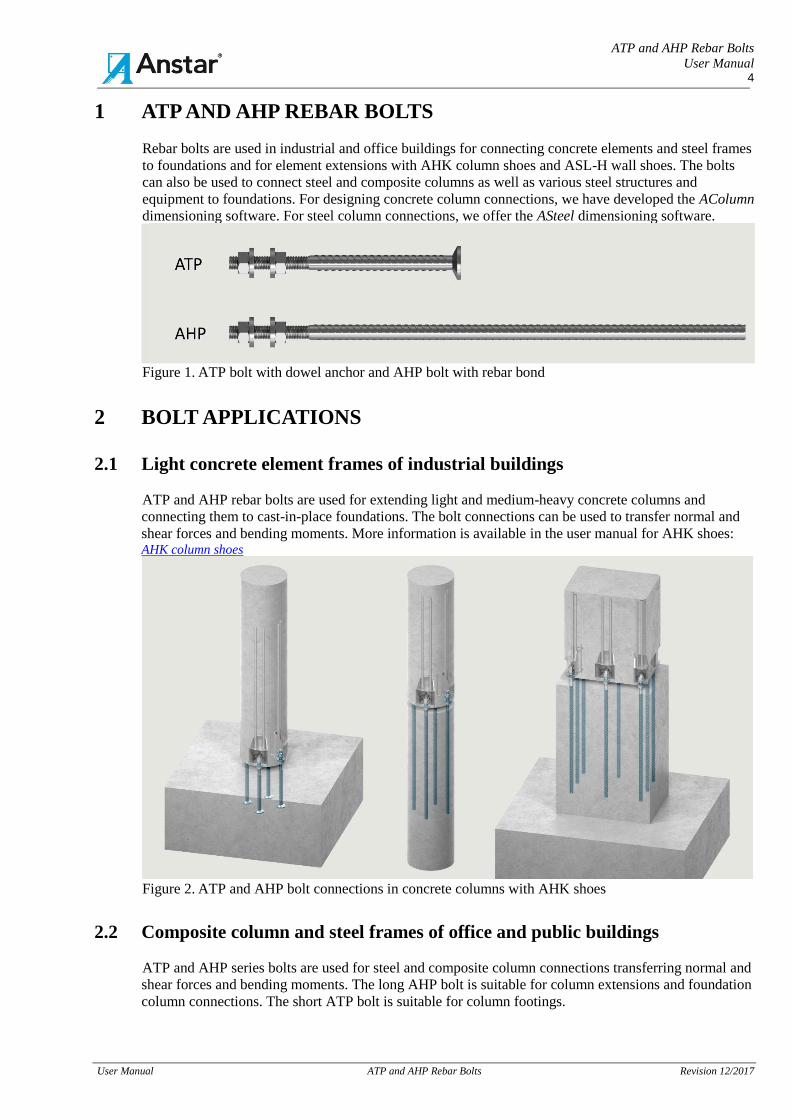
1 ATP AND AHP REBAR BOLTS
Rebar bolts are used in industrial and office buildings for connecting concrete elements and steel frames
to foundations and for element extensions with AHK column shoes and ASL-H wall shoes. The bolts
can also be used to connect steel and composite columns as well as various steel structures and
equipment to foundations. For designing concrete column connections, we have developed the AColumn
dimensioning software. For steel column connections, we offer the ASteel dimensioning software.
Figure 1. ATP bolt with dowel anchor and AHP bolt with rebar bond
2 BOLT APPLICATIONS
2.1 Light concrete element frames of industrial buildings
ATP and AHP rebar bolts are used for extending light and medium-heavy concrete columns and
connecting them to cast-in-place foundations. The bolt connections can be used to transfer normal and
shear forces and bending moments. More information is available in the user manual for AHK shoes: AHK column shoes
Figure 2. ATP and AHP bolt connections in concrete columns with AHK shoes
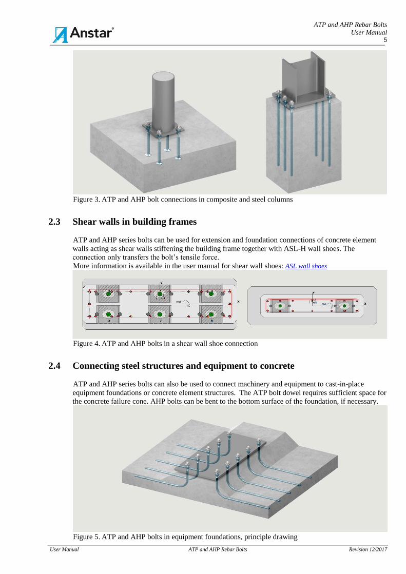
2.2 Composite column and steel frames of office and public buildings
ATP and AHP series bolts are used for steel and composite column connections transferring normal and
shear forces and bending moments. The long AHP bolt is suitable for column extensions and foundation
column connections. The short ATP bolt is suitable for column footings.
ATP and AHP Rebar Bolts
User Manual 5
User Manual ATP and AHP Rebar Bolts Revision 12/2017
Figure 3. ATP and AHP bolt connections in composite and steel columns
2.3 Shear walls in building frames
ATP and AHP series bolts can be used for extension and foundation connections of concrete element
walls acting as shear walls stiffening the building frame together with ASL-H wall shoes. The
connection only transfers the bolt’s tensile force.
More information is available in the user manual for shear wall shoes: ASL wall shoes
Figure 4. ATP and AHP bolts in a shear wall shoe connection
2.4 Connecting steel structures and equipment to concrete
ATP and AHP series bolts can also be used to connect machinery and equipment to cast-in-place
equipment foundations or concrete element structures. The ATP bolt dowel requires sufficient space for
the concrete failure cone. AHP bolts can be bent to the bottom surface of the foundation, if necessary.
Figure 5. ATP and AHP bolts in equipment foundations, principle drawing
ATP and AHP Rebar Bolts
User Manual 6
User Manual ATP and AHP Rebar Bolts Revision 12/2017
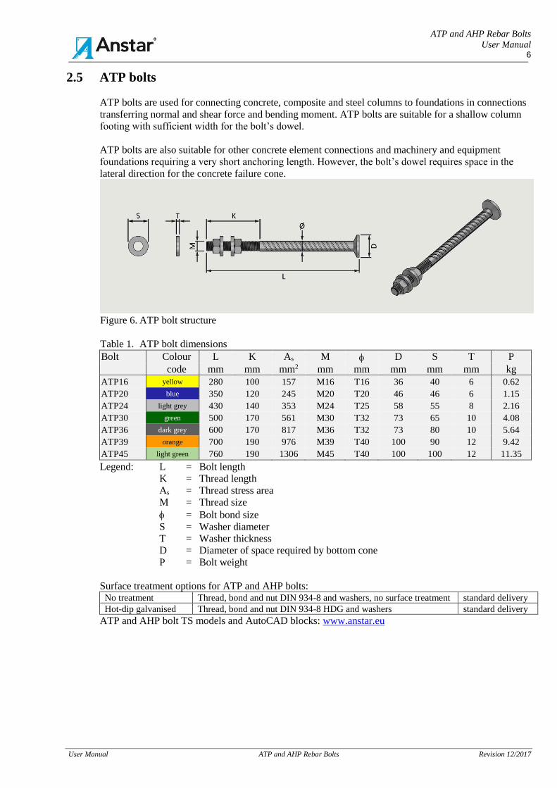
2.5 ATP bolts
ATP bolts are used for connecting concrete, composite and steel columns to foundations in connections
transferring normal and shear force and bending moment. ATP bolts are suitable for a shallow column
footing with sufficient width for the bolt’s dowel.
ATP bolts are also suitable for other concrete element connections and machinery and equipment
foundations requiring a very short anchoring length. However, the bolt’s dowel requires space in the
lateral direction for the concrete failure cone.
Figure 6. ATP bolt structure
Table 1. ATP bolt dimensions Bolt Colour L K As M D S T P
code mm mm mm2 mm mm mm mm mm kg
ATP16 yellow 280 100 157 M16 T16 36 40 6 0.62
ATP20 blue 350 120 245 M20 T20 46 46 6 1.15
ATP24 light grey 430 140 353 M24 T25 58 55 8 2.16
ATP30 green 500 170 561 M30 T32 73 65 10 4.08
ATP36 dark grey 600 170 817 M36 T32 73 80 10 5.64
ATP39 orange 700 190 976 M39 T40 100 90 12 9.42
ATP45 light green 760 190 1306 M45 T40 100 100 12 11.35 Legend: L = Bolt length
K = Thread length
As = Thread stress area
M = Thread size
= Bolt bond size
S = Washer diameter
T = Washer thickness
D = Diameter of space required by bottom cone
P = Bolt weight
Surface treatment options for ATP and AHP bolts: No treatment Thread, bond and nut DIN 934-8 and washers, no surface treatment standard delivery
Hot-dip galvanised Thread, bond and nut DIN 934-8 HDG and washers standard delivery
ATP and AHP bolt TS models and AutoCAD blocks: www.anstar.eu
ATP and AHP Rebar Bolts
User Manual 7
User Manual ATP and AHP Rebar Bolts Revision 12/2017
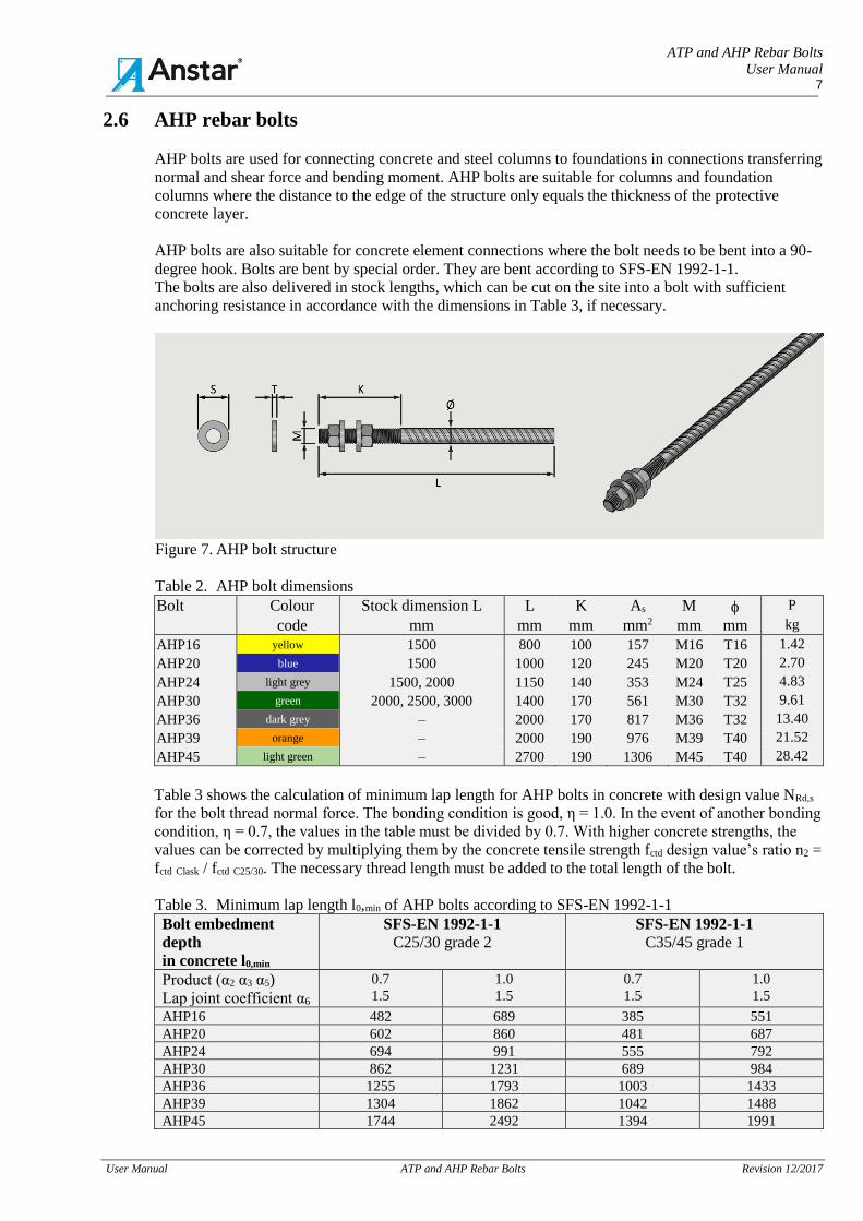
2.6 AHP rebar bolts
AHP bolts are used for connecting concrete and steel columns to foundations in connections transferring
normal and shear force and bending moment. AHP bolts are suitable for columns and foundation
columns where the distance to the edge of the structure only equals the thickness of the protective
concrete layer.
AHP bolts are also suitable for concrete element connections where the bolt needs to be bent into a 90-
degree hook. Bolts are bent by special order. They are bent according to SFS-EN 1992-1-1.
The bolts are also delivered in stock lengths, which can be cut on the site into a bolt with sufficient
anchoring resistance in accordance with the dimensions in Table 3, if necessary.
Figure 7. AHP bolt structure
Table 2. AHP bolt dimensions Bolt Colour Stock dimension L L K As M P
code mm mm mm mm2 mm mm kg
AHP16 yellow 1500 800 100 157 M16 T16 1.42
AHP20 blue 1500 1000 120 245 M20 T20 2.70
AHP24 light grey 1500, 2000 1150 140 353 M24 T25 4.83
AHP30 green 2000, 2500, 3000 1400 170 561 M30 T32 9.61
AHP36 dark grey – 2000 170 817 M36 T32 13.40
AHP39 orange – 2000 190 976 M39 T40 21.52
AHP45 light green – 2700 190 1306 M45 T40 28.42
Table 3 shows the calculation of minimum lap length for AHP bolts in concrete with design value NRd,s
for the bolt thread normal force. The bonding condition is good, η = 1.0. In the event of another bonding
condition, η = 0.7, the values in the table must be divided by 0.7. With higher concrete strengths, the
values can be corrected by multiplying them by the concrete tensile strength fctd design value’s ratio n2 =
fctd Clask / fctd C25/30. The necessary thread length must be added to the total length of the bolt.
Table 3. Minimum lap length l0,min of AHP bolts according to SFS-EN 1992-1-1
Bolt embedment
depth
in concrete l0,min
SFS-EN 1992-1-1
C25/30 grade 2
SFS-EN 1992-1-1
C35/45 grade 1
Product (α2 α3 α5)
Lap joint coefficient α6
0.7
1.5
1.0
1.5
0.7
1.5
1.0
1.5
AHP16 482 689 385 551
AHP20 602 860 481 687
AHP24 694 991 555 792
AHP30 862 1231 689 984
AHP36 1255 1793 1003 1433
AHP39 1304 1862 1042 1488
AHP45 1744 2492 1394 1991
ATP and AHP Rebar Bolts
User Manual 8
User Manual ATP and AHP Rebar Bolts Revision 12/2017
3 MANUFACTURING INFORMATION
ANSTAR Oy has entered into a quality control agreement with Inspecta Sertifiointi Oy regarding the
manufacture of ATP and AHP bolts. The manufacturing information for the bolts is as follows:
Manufacturing
markings
Bolt manufacturing markings:
- ANSTAR Oy’s code
- Manufacture according to SFS-EN 1090-2 for steel parts. [2]
- Bolt code is painted on the head with a colour code.
- Packaging: pallet
Materials
Manufacturing materials:
- Rebar SFS-EN 10080, B500B
- Nut DIN 934, strength 8
- Washer SFS-EN 10025 black/galvanised, S355J2+N
- Impact test temperature for the materials: –20 oC
Manufacturing
method
Bolt manufacture:
- Bolts are manufactured according to the SFS-EN 1090-2 standard in execution
class EXC2.
By special order, bolts can be manufactured in execution class EXC3. [2]
- Thread, rolling
- Dowel anchor, hot forming
- Manufacturing tolerances SFS-EN 1090-2 [2]
Surface
treatment
methods
Standard delivery 1: No treatment
- Thread and bond without surface treatment, thread oiled
- Nuts DIN 934, strength 8, no treatment
- Washers S355J2+N, no treatment
Standard delivery 2: Hot-dip galvanised, order code HDG
- Thread and bond hot-dip galvanised, SFS-EN ISO 10684
- Nuts DIN 934, strength 8, oversized, hot-dip galvanised
- Washers S355J2+N, hot-dip galvanised
Bolts manufactured by Anstar Oy grouped according to their application:
Table 4. Bolt manufacturing programme and user manuals
Bolts User manual Typical application
1 ATP
AHP
ATP and AHP rebar
bolts
- Foundation bolt connections in office, commercial and
public buildings. Concrete and steel frames as well as
composite column frames.
- Bolt connections of light industrial building foundations in
concrete and steel frames
- Light connections of machinery and equipment foundations
to concrete
2 ALP-LC
ALP-PC
ALP-P2
and S series
with
removable
thread
ALP-C anchor bolts - Heavy-duty foundation connections of industrial concrete
element frames
- Moment stiff beam-to-column connections in concrete
element frames
- Foundation connections in shear walls
- Heavy-duty column-to-foundation connections in steel
frames
- Other heavy-duty bolt connections to concrete
- Heavy-duty connections of machinery and equipment
foundations to concrete
3 ARJ Reinforcement
coupler
- Reinforcement coupler connection
- Bolt applications in reinforcement couplers
- Moment stiff beam-to-column connection
- Tension bar structures
ATP and AHP Rebar Bolts
User Manual 9
User Manual ATP and AHP Rebar Bolts Revision 12/2017
4 BOLT DIMENSIONING CRITERIA
4.1 Design and manufacturing standards
The design and manufacturing standards for ATP and AHP series rebar bolts are:
1. Finnish standards
In Finland, the bolts are used for applications designed in accordance with the following standards:
SFS-EN 1991-1+NA Actions on structures. Part 1-1: General actions. [5]
SFS-EN 1992-1+NA Design of concrete structures. Part 1-1: General rules and rules for buildings. [6]
SFS-EN 1993-1-
1+NA
Design of steel structures. Part 1-1: General rules and rules for buildings. [7]
SFS-EN 13670 Execution of concrete structures, execution class 2 or 3, [17]
CEN/TS 1992-4-1 Design of fastenings for use in concrete – Part 4-1: General.[9]
CEN/TS 1992-4-2 Design of fastenings for use in concrete – Part 4-2: Headed Fasteners[10].
2. Other countries in the European Standards area
Bolt resistances have been checked according to EN standards.
Basic Eurocode EN-1992-1-1:2004/AC:2010
Sweden SS-EN 1992-1-1:2005/AC:2010+A1/2014
Germany DIN-EN 1992-1 +NA/2013-04
3. Bolt manufacture
Bolts are manufactured according to the SFS-EN 1090-2 standard in execution class EXC2 or
EXC3.
The bolts meet the requirements of the following standards:
SFS-EN 1090-1 Execution of steel structures. Part 1: Requirements for conformity assessment of
structural components. [1]
SFS-EN 1090-2 Execution of steel structures. Part 2: Technical requirements for steel structures.
Execution classes EXC2 and EXC3. [2]
SFS-EN 13670 Execution of concrete structures. Execution class 2 or 3. [17]
SFS-EN-ISO 5817 Welding. Fusion-welded joints in steel, nickel, titanium and their alloys. Weld
classes. [11]
SFS-EN 17760-1 Welding. Welding of reinforcing steel. Part 1: Load-bearing welded joints. [16]
4.2 Bolt resistance values
4.2.1 Normal force resistance of bolts
The design value of a bolt’s normal force resistance is determined by the resistance of its thread. The
design value for the bolt’s thread is calculated according to CEN/TS 1992-4-2, Section 6.2[10]. The
design values for the normal force resistance of bolts are indicated in Table 5.
The bolt’s shear resistance in the concrete of the foundations is calculated according to CEN/TS 1992-4-
2, Section 6.3. The shear force transfer method for the connection is selected in the AColumn or ASteel
software to suit each situation; refer to Section 4.3.
The normal force and shear resistance of a bolt connection during installation before grouting is also
calculated using the software. The calculation principle is provided in Section 4.2.4.
The normal and shear forces on the bolt are transferred to the foundation reinforcement. Supplementary
reinforcement is specified for each failure criterion of the bolt. The joint action of supplementary
stirrups and bolt bonds with the foundation concrete and main reinforcement is calculated using the
software. The bolts are also subjected to accident scenario resistance analysis.
ATP and AHP Rebar Bolts
User Manual 10
User Manual ATP and AHP Rebar Bolts Revision 12/2017
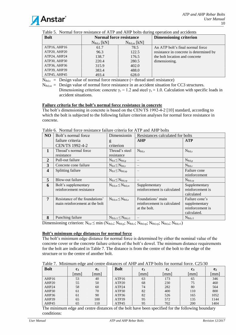
Table 5. Normal force resistance of ATP and AHP bolts during operation and accidents
Bolt
Normal force resistance
NRd,s [kN] NRd,sa [kN]
Dimensioning criterion
ATP16, AHP16 61.7 78.5 An ATP bolt’s final normal force ATP20, AHP20 96.3 122.5 resistance in concrete is determined by ATP24, AHP24 138.7 176.5 the bolt location and concrete ATP30, AHP30 220.4 280.5 dimensioning. ATP36, AHP36 315.9 402.0 ATP39, AHP39 383.4 488.0 ATP45, AHP45 493.4 628.0
NRd,s = Design value of normal force resistance (= thread steel resistance)
NRd,sa = Design value of normal force resistance in an accident situation for CC3 structures.
Dimensioning criterion: concrete γc = 1.2 and steel γs = 1.0. Calculation with specific loads in
accident situations.
Failure criteria for the bolt’s normal force resistance in concrete
The bolt’s dimensioning in concrete is based on the CEN/TS 1992-4-2 [10] standard, according to
which the bolt is subjected to the following failure criterion analyses for normal force resistance in
concrete.
Table 6. Normal force resistance failure criteria for ATP and AHP bolts
NO Bolt’s normal force
failure criteria
CEN/TS 1992-4-2
Dimensionin
g
criterion
Resistances calculated for bolts
AHP
ATP
1 Thread’s normal force
resistance
Thread’s steel
resistance
NRd,s NRd,s
2 Pull-out failure NEd ≤ NRd,p – NRd,p
3 Concrete cone failure NEd ≤ NRd,c – NRd,c
4 Splitting failure NEd ≤ NRd,sp – Failure cone
reinforcement
5 Blow-out failure NEd ≤ NRd,cp – NRd,cp
6 Bolt’s supplementary
reinforcement resistance
NEd,re ≤ NRd,re Supplementary
reinforcement is calculated
Supplementary
reinforcement is
calculated
7 Resistance of the foundations’
main reinforcement at the bolt
NEd,ra ≤ NRd,a Foundations’ main
reinforcement is calculated
at the bolt.
Failure cone’s
supplementary
reinforcement is
calculated.
8 Punching failure NEd,c1 ≤ NRd,c1 – NRd,c1
Dimensioning criterion: NEd ≤ min (NRd,s; NRd,p; NRd,c; NRd,sp; NRd,cp; NRd,a; NRd,c1)
Bolt’s minimum edge distances for normal force
The bolt’s minimum edge distance for normal force is determined by either the nominal value of the
concrete cover or the concrete failure criteria of the bolt’s dowel. The minimum distance requirements
for the bolt are indicated in Table 7. The distance is from the centre of the bolt to the edge of the
structure or to the centre of another bolt.
Table 7. Minimum edge and centre distances of AHP and ATP bolts for normal force. C25/30
Bolt c1
[mm]
e1
[mm]
Bolt c1
[mm]
c2
[mm]
c3
[mm]
e2
[mm] AHP16 53 40 ATP16 63 173 65 346
AHP20 55 50 ATP20 68 230 75 460
AHP24 58 60 ATP24 74 282 80 564
AHP30 61 70 ATP30 82 400 110 800
AHP36 61 90 ATP36 82 526 165 1052
AHP39 65 100 ATP39 95 572 135 1144
AHP45 65 110 ATP45 95 702 200 1404
The minimum edge and centre distances of the bolt have been specified for the following boundary
conditions:
ATP and AHP Rebar Bolts
User Manual 11
User Manual ATP and AHP Rebar Bolts Revision 12/2017
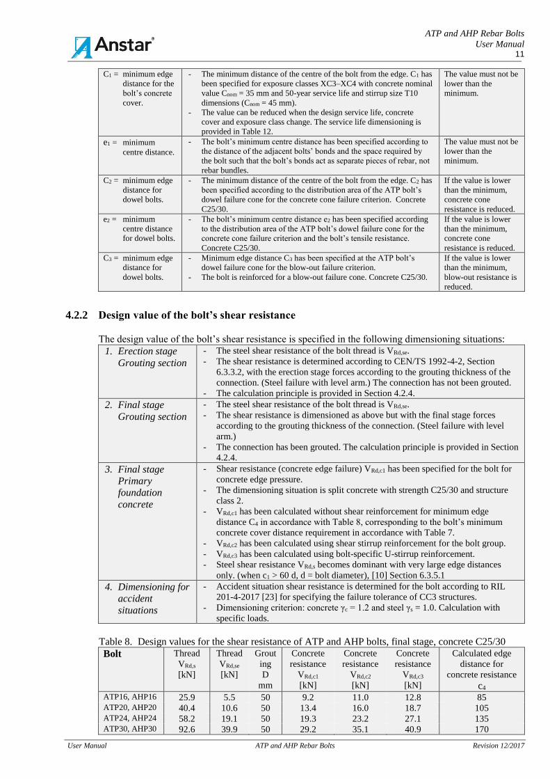
C1 = minimum edge
distance for the
bolt’s concrete
cover.
- The minimum distance of the centre of the bolt from the edge. C1 has
been specified for exposure classes XC3–XC4 with concrete nominal
value Cnom = 35 mm and 50-year service life and stirrup size T10
dimensions (Cnom = 45 mm).
- The value can be reduced when the design service life, concrete
cover and exposure class change. The service life dimensioning is
provided in Table 12.
The value must not be
lower than the
minimum.
e1 = minimum
centre distance.
- The bolt’s minimum centre distance has been specified according to
the distance of the adjacent bolts’ bonds and the space required by
the bolt such that the bolt’s bonds act as separate pieces of rebar, not
rebar bundles.
The value must not be
lower than the
minimum.
C2 = minimum edge
distance for
dowel bolts.
- The minimum distance of the centre of the bolt from the edge. C2 has
been specified according to the distribution area of the ATP bolt’s
dowel failure cone for the concrete cone failure criterion. Concrete
C25/30.
If the value is lower
than the minimum,
concrete cone
resistance is reduced.
e2 = minimum
centre distance
for dowel bolts.
- The bolt’s minimum centre distance e2 has been specified according
to the distribution area of the ATP bolt’s dowel failure cone for the
concrete cone failure criterion and the bolt’s tensile resistance.
Concrete C25/30.
If the value is lower
than the minimum,
concrete cone
resistance is reduced.
C3 = minimum edge
distance for
dowel bolts.
- Minimum edge distance C3 has been specified at the ATP bolt’s
dowel failure cone for the blow-out failure criterion.
- The bolt is reinforced for a blow-out failure cone. Concrete C25/30.
If the value is lower
than the minimum,
blow-out resistance is
reduced.
4.2.2 Design value of the bolt’s shear resistance
The design value of the bolt’s shear resistance is specified in the following dimensioning situations:
1. Erection stage
Grouting section
- The steel shear resistance of the bolt thread is VRd,se.
- The shear resistance is determined according to CEN/TS 1992-4-2, Section
6.3.3.2, with the erection stage forces according to the grouting thickness of the
connection. (Steel failure with level arm.) The connection has not been grouted.
- The calculation principle is provided in Section 4.2.4.
2. Final stage
Grouting section
- The steel shear resistance of the bolt thread is VRd,se.
- The shear resistance is dimensioned as above but with the final stage forces
according to the grouting thickness of the connection. (Steel failure with level
arm.)
- The connection has been grouted. The calculation principle is provided in Section
4.2.4.
3. Final stage
Primary
foundation
concrete
- Shear resistance (concrete edge failure) VRd,c1 has been specified for the bolt for
concrete edge pressure.
- The dimensioning situation is split concrete with strength C25/30 and structure
class 2.
- VRd,c1 has been calculated without shear reinforcement for minimum edge
distance C4 in accordance with Table 8, corresponding to the bolt’s minimum
concrete cover distance requirement in accordance with Table 7.
- VRd,c2 has been calculated using shear stirrup reinforcement for the bolt group.
- VRd,c3 has been calculated using bolt-specific U-stirrup reinforcement.
- Steel shear resistance VRd,s becomes dominant with very large edge distances
only. (when c1 > 60 d, d = bolt diameter), [10] Section 6.3.5.1
4. Dimensioning for
accident
situations
- Accident situation shear resistance is determined for the bolt according to RIL
201-4-2017 [23] for specifying the failure tolerance of CC3 structures.
- Dimensioning criterion: concrete γc = 1.2 and steel γs = 1.0. Calculation with
specific loads.
Table 8. Design values for the shear resistance of ATP and AHP bolts, final stage, concrete C25/30
Bolt Thread
VRd,s
[kN]
Thread
VRd,se
[kN]
Grout
ing
D
mm
Concrete
resistance
VRd,c1
[kN]
Concrete
resistance
VRd,c2
[kN]
Concrete
resistance
VRd,c3
[kN]
Calculated edge
distance for
concrete resistance
c4 ATP16, AHP16 25.9 5.5 50 9.2 11.0 12.8 85 ATP20, AHP20 40.4 10.6 50 13.4 16.0 18.7 105 ATP24, AHP24 58.2 19.1 50 19.3 23.2 27.1 135 ATP30, AHP30 92.6 39.9 50 29.2 35.1 40.9 170
ATP and AHP Rebar Bolts
User Manual 12
User Manual ATP and AHP Rebar Bolts Revision 12/2017
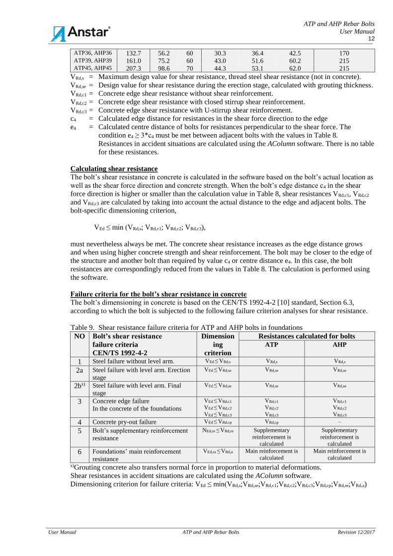
ATP36, AHP36 132.7 56.2 60 30.3 36.4 42.5 170 ATP39, AHP39 161.0 75.2 60 43.0 51.6 60.2 215 ATP45, AHP45 207.3 98.6 70 44.3 53.1 62.0 215
VRd,s = Maximum design value for shear resistance, thread steel shear resistance (not in concrete).
VRd,se = Design value for shear resistance during the erection stage, calculated with grouting thickness.
VRd,c1 = Concrete edge shear resistance without shear reinforcement.
VRd,c2 = Concrete edge shear resistance with closed stirrup shear reinforcement.
VRd,c3 = Concrete edge shear resistance with U-stirrup shear reinforcement.
c4 = Calculated edge distance for resistances in the shear force direction to the edge
e4 = Calculated centre distance of bolts for resistances perpendicular to the shear force. The
condition e4 ≥ 3*c4 must be met between adjacent bolts with the values in Table 8.
Resistances in accident situations are calculated using the AColumn software. There is no table
for these resistances.
Calculating shear resistance
The bolt’s shear resistance in concrete is calculated in the software based on the bolt’s actual location as
well as the shear force direction and concrete strength. When the bolt’s edge distance c4 in the shear
force direction is higher or smaller than the calculation value in Table 8, shear resistances VRd,c1, VRd,c2
and VRd,c3 are calculated by taking into account the actual distance to the edge and adjacent bolts. The
bolt-specific dimensioning criterion,
VEd ≤ min (VRd,s; VRd,c1; VRd,c2; VRd,c3),
must nevertheless always be met. The concrete shear resistance increases as the edge distance grows
and when using higher concrete strength and shear reinforcement. The bolt may be closer to the edge of
the structure and another bolt than required by value c4 or centre distance e4. In this case, the bolt
resistances are correspondingly reduced from the values in Table 8. The calculation is performed using
the software.
Failure criteria for the bolt’s shear resistance in concrete
The bolt’s dimensioning in concrete is based on the CEN/TS 1992-4-2 [10] standard, Section 6.3,
according to which the bolt is subjected to the following failure criterion analyses for shear resistance.
Table 9. Shear resistance failure criteria for ATP and AHP bolts in foundations
NO Bolt’s shear resistance
failure criteria
CEN/TS 1992-4-2
Dimension
ing
criterion
Resistances calculated for bolts
ATP
AHP
1 Steel failure without level arm. VEd ≤ VRd,s VRd,s VRd,s
2a Steel failure with level arm. Erection
stage
VEd ≤ VRd,se VRd,se VRd,se
2bx) Steel failure with level arm. Final
stage
VEd ≤ VRd,se VRd,se VRd,se
3 Concrete edge failure
In the concrete of the foundations
VEd ≤ VRd,c1
VEd ≤ VRd,c2
VEd ≤ VRd,c3
VRd,c1
VRd,c2
VRd,c3
VRd,c1
VRd,c2
VRd,c3
4 Concrete pry-out failure VEd ≤ VRd,cp VRd,cp –
5 Bolt’s supplementary reinforcement
resistance
NEd,re ≤ VRd,re Supplementary
reinforcement is
calculated
Supplementary
reinforcement is
calculated
6 Foundations’ main reinforcement
resistance
VEd,ra ≤ VRd,a Main reinforcement is
calculated
Main reinforcement is
calculated
x)Grouting concrete also transfers normal force in proportion to material deformations.
Shear resistances in accident situations are calculated using the AColumn software.
Dimensioning criterion for failure criteria: VEd ≤ min(VRd,s;VRd,se;VRd,c1;VRd,c2;VRd,c3;VRd,cp;VRd,re;VRd,a)
ATP and AHP Rebar Bolts
User Manual 13
User Manual ATP and AHP Rebar Bolts Revision 12/2017
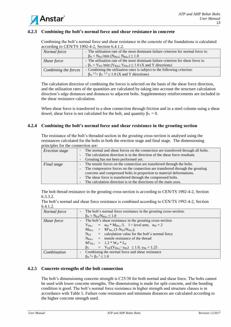
4.2.3 Combining the bolt’s normal force and shear resistance in concrete
Combining the bolt’s normal force and shear resistance in the concrete of the foundations is calculated
according to CEN/TS 1992-4-2, Section 6.4.1.2.
Normal force - The utilisation rate of the most dominant failure criterion for normal force is:
βN = NEd /min (NRd,s; NRd,c) ≤ 1.0
Shear force - The utilisation rate of the most dominant failure criterion for shear force is:
- βV = VEd /min (VRd,s; VRd,c) ≤ 1.0 (X and Y directions)
Combining the forces - Combining the utilisation rates is subject to the following criterion:
βN 1,5+ βV 1,5 ≤ 1.0 (X and Y directions)
The calculation direction of combining the forces is selected on the basis of the shear force direction,
and the utilisation rates of the quantities are calculated by taking into account the structure calculation
direction’s edge distances and distances to adjacent bolts. Supplementary reinforcements are included in
the shear resistance calculation.
When shear force is transferred in a shoe connection through friction and in a steel column using a shear
dowel, shear force is not calculated for the bolt, and quantity βV = 0.
4.2.4 Combining the bolt’s normal force and shear resistance in the grouting section
The resistance of the bolt’s threaded section in the grouting cross-section is analysed using the
resistances calculated for the bolts in both the erection stage and final stage. The dimensioning
principles for the connection are:
Erection stage - The normal and shear forces on the connection are transferred through all bolts.
- The calculation direction is in the direction of the shear force resultant.
- Grouting has not been performed yet.
Final stage - The tensile forces on the connection are transferred through the bolts.
- The compressive forces on the connection are transferred through the grouting
concrete and compressed bolts in proportion to material deformations.
- The shear force is transferred through the compressed bolts.
- The calculation direction is in the directions of the main axes.
The bolt thread resistance in the grouting cross-section is according to CEN/TS 1992-4-2, Section
6.3.3.2.
The bolt’s normal and shear force resistance is combined according to CEN/TS 1992-4-2, Section
6.4.1.2.
Normal force - The bolt’s normal force resistance in the grouting cross-section:
βN = NEd/NRd,s ≤ 1,0
Shear force - The bolt’s shear resistance in the grouting cross-section
VRk,s = αM * MRk,s /l, l = level arm, αM = 2
MRk,s = MoRk,s (1-NEd/NRd,s),
NEd = calculation value for the bolt’s normal force
NRd,s = tensile resistance of the thread
MoRk,s = 1.2 * Wel * fuk
βV = VEd/(VRk,s / γMs) ≤ 1.0, γMs = 1.25
Combination - Combining the normal force and shear resistance
βN 2+ βV
2 ≤ 1.0
4.2.5 Concrete strengths of the bolt connection
The bolt’s dimensioning concrete strength is C25/30 for both normal and shear force. The bolts cannot
be used with lower concrete strengths. The dimensioning is made for split concrete, and the bonding
condition is good. The bolt’s normal force resistance in higher strength and structure classes is in
accordance with Table 5. Failure cone resistances and minimum distances are calculated according to
the higher concrete strength used.
ATP and AHP Rebar Bolts
User Manual 14
User Manual ATP and AHP Rebar Bolts Revision 12/2017
The bolt’s shear resistance in concrete is always calculated according to the foundations’ actual concrete
strength and the bolt’s edge and centre distance. The concrete shear resistance increases as the edge and
centre distance and concrete strength increase. The values in Table 8 are values for the bolt’s minimum
dimensioning situation with edge distance c4 provided in the table.
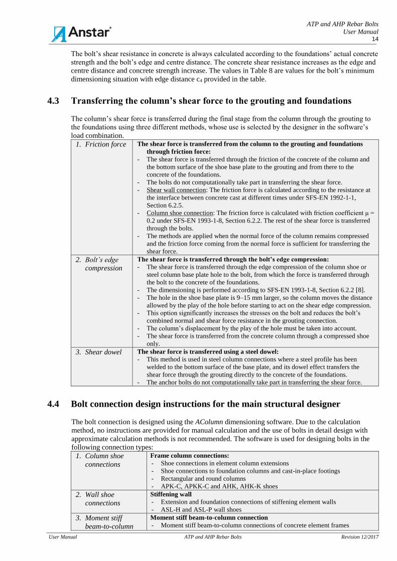
4.3 Transferring the column’s shear force to the grouting and foundations
The column’s shear force is transferred during the final stage from the column through the grouting to
the foundations using three different methods, whose use is selected by the designer in the software’s
load combination.
1. Friction force
The shear force is transferred from the column to the grouting and foundations
through friction force:
- The shear force is transferred through the friction of the concrete of the column and
the bottom surface of the shoe base plate to the grouting and from there to the
concrete of the foundations.
- The bolts do not computationally take part in transferring the shear force.
- Shear wall connection: The friction force is calculated according to the resistance at
the interface between concrete cast at different times under SFS-EN 1992-1-1,
Section 6.2.5.
- Column shoe connection: The friction force is calculated with friction coefficient μ =
0.2 under SFS-EN 1993-1-8, Section 6.2.2. The rest of the shear force is transferred
through the bolts.
- The methods are applied when the normal force of the column remains compressed
and the friction force coming from the normal force is sufficient for transferring the
shear force.
2. Bolt’s edge
compression
The shear force is transferred through the bolt’s edge compression:
- The shear force is transferred through the edge compression of the column shoe or
steel column base plate hole to the bolt, from which the force is transferred through
the bolt to the concrete of the foundations.
- The dimensioning is performed according to SFS-EN 1993-1-8, Section 6.2.2 [8].
- The hole in the shoe base plate is 9–15 mm larger, so the column moves the distance
allowed by the play of the hole before starting to act on the shear edge compression.
- This option significantly increases the stresses on the bolt and reduces the bolt’s
combined normal and shear force resistance in the grouting connection.
- The column’s displacement by the play of the hole must be taken into account.
- The shear force is transferred from the concrete column through a compressed shoe
only.
3. Shear dowel
The shear force is transferred using a steel dowel:
- This method is used in steel column connections where a steel profile has been
welded to the bottom surface of the base plate, and its dowel effect transfers the
shear force through the grouting directly to the concrete of the foundations.
- The anchor bolts do not computationally take part in transferring the shear force.
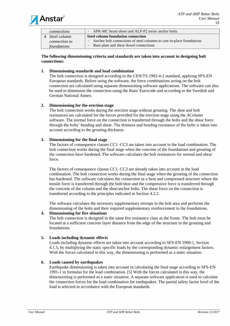
4.4 Bolt connection design instructions for the main structural designer
The bolt connection is designed using the AColumn dimensioning software. Due to the calculation
method, no instructions are provided for manual calculation and the use of bolts in detail design with
approximate calculation methods is not recommended. The software is used for designing bolts in the
following connection types:
1. Column shoe
connections
Frame column connections:
- Shoe connections in element column extensions
- Shoe connections to foundation columns and cast-in-place footings
- Rectangular and round columns
- APK-C, APKK-C and AHK, AHK-K shoes
2. Wall shoe
connections
Stiffening wall
- Extension and foundation connections of stiffening element walls
- ASL-H and ASL-P wall shoes
3. Moment stiff
beam-to-column
Moment stiff beam-to-column connection
- Moment stiff beam-to-column connections of concrete element frames
ATP and AHP Rebar Bolts
User Manual 15
User Manual ATP and AHP Rebar Bolts Revision 12/2017
connections - APK-MC beam shoes and ALP-P2 series anchor bolts.
4. Steel column
connection to
foundations
Steel column foundation connection
- Anchor bolt connections of steel columns to cast-in-place foundations
- Base plate and shear dowel connections
The following dimensioning criteria and standards are taken into account in designing bolt
connections:
1. Dimensioning standards and load combination
The bolt connection is designed according to the CEN/TS 1992-4-2 standard, applying SFS-EN
European standards. Before using the software, the force combinations acting on the bolt
connection are calculated using separate dimensioning software applications. The software can also
be used to dimension the connection using the Basic Eurocode and according to the Swedish and
German National Annex.
2. Dimensioning for the erection stage
The bolt connection works during the erection stage without grouting. The shoe and bolt
resistances are calculated for the forces provided for the erection stage using the AColumn
software. The normal force on the connection is transferred through the bolts and the shear force
through the bolts’ bending and shear. The thinness and bending resistance of the bolts is taken into
account according to the grouting thickness.
3. Dimensioning for the final stage
The factors of consequence classes CC1–CC3 are taken into account in the load combination. The
bolt connection works during the final stage when the concrete of the foundations and grouting of
the connection have hardened. The software calculates the bolt resistances for normal and shear
force.
The factors of consequence classes CC1–CC3 are already taken into account in the load
combination. The bolt connection works during the final stage when the grouting of the connection
has hardened. The software calculates the connection as a bent and compressed structure where the
tensile force is transferred through the bolt/shoe and the compressive force is transferred through
the concrete of the column and the shoe/anchor bolts. The shear force on the connection is
transferred according to the principles indicated in Section 4.2.2.
The software calculates the necessary supplementary stirrups in the bolt area and performs the
dimensioning of the bolts and their required supplementary reinforcement in the foundations.
4. Dimensioning for fire situations
The bolt connection is designed in the same fire resistance class as the frame. The bolt must be
located at a sufficient concrete layer distance from the edge of the structure in the grouting and
foundations.
5. Loads including dynamic effects
Loads including dynamic effects are taken into account according to SFS-EN 1990-1, Section
4.1.5, by multiplying the static specific loads by the corresponding dynamic enlargement factors.
With the forces calculated in this way, the dimensioning is performed as a static situation.
6. Loads caused by earthquakes
Earthquake dimensioning is taken into account in calculating the final stage according to SFS-EN
1991-1 in formulas for the load combination. [5] With the forces calculated in this way, the
dimensioning is performed as a static situation. A separate software application is used to calculate
the connection forces for the load combination for earthquakes. The partial safety factor level of the
load is selected in accordance with the European standards.
ATP and AHP Rebar Bolts
User Manual 16
User Manual ATP and AHP Rebar Bolts Revision 12/2017
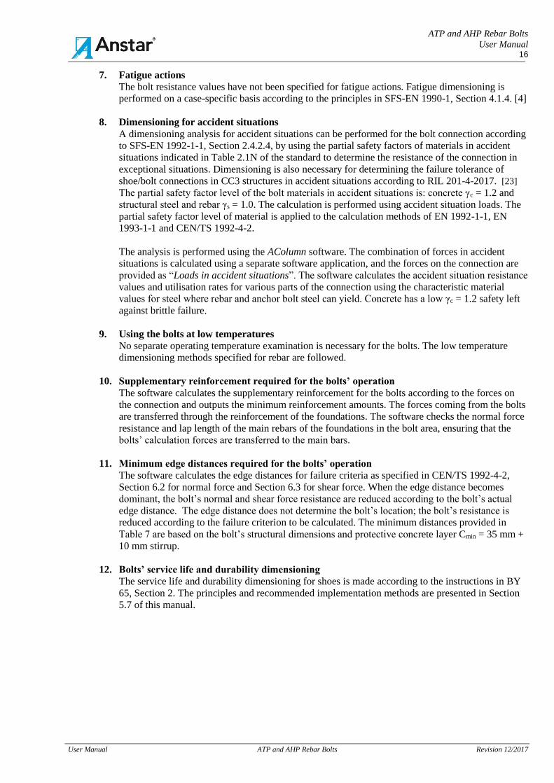
7. Fatigue actions
The bolt resistance values have not been specified for fatigue actions. Fatigue dimensioning is
performed on a case-specific basis according to the principles in SFS-EN 1990-1, Section 4.1.4. [4]
8. Dimensioning for accident situations
A dimensioning analysis for accident situations can be performed for the bolt connection according
to SFS-EN 1992-1-1, Section 2.4.2.4, by using the partial safety factors of materials in accident
situations indicated in Table 2.1N of the standard to determine the resistance of the connection in
exceptional situations. Dimensioning is also necessary for determining the failure tolerance of
shoe/bolt connections in CC3 structures in accident situations according to RIL 201-4-2017. [23]
The partial safety factor level of the bolt materials in accident situations is: concrete γc = 1.2 and
structural steel and rebar γs = 1.0. The calculation is performed using accident situation loads. The
partial safety factor level of material is applied to the calculation methods of EN 1992-1-1, EN
1993-1-1 and CEN/TS 1992-4-2.
The analysis is performed using the AColumn software. The combination of forces in accident
situations is calculated using a separate software application, and the forces on the connection are
provided as “Loads in accident situations”. The software calculates the accident situation resistance
values and utilisation rates for various parts of the connection using the characteristic material
values for steel where rebar and anchor bolt steel can yield. Concrete has a low γc = 1.2 safety left
against brittle failure.
9. Using the bolts at low temperatures
No separate operating temperature examination is necessary for the bolts. The low temperature
dimensioning methods specified for rebar are followed.
10. Supplementary reinforcement required for the bolts’ operation
The software calculates the supplementary reinforcement for the bolts according to the forces on
the connection and outputs the minimum reinforcement amounts. The forces coming from the bolts
are transferred through the reinforcement of the foundations. The software checks the normal force
resistance and lap length of the main rebars of the foundations in the bolt area, ensuring that the
bolts’ calculation forces are transferred to the main bars.
11. Minimum edge distances required for the bolts’ operation
The software calculates the edge distances for failure criteria as specified in CEN/TS 1992-4-2,
Section 6.2 for normal force and Section 6.3 for shear force. When the edge distance becomes
dominant, the bolt’s normal and shear force resistance are reduced according to the bolt’s actual
edge distance. The edge distance does not determine the bolt’s location; the bolt’s resistance is
reduced according to the failure criterion to be calculated. The minimum distances provided in
Table 7 are based on the bolt’s structural dimensions and protective concrete layer Cmin = 35 mm +
10 mm stirrup.
12. Bolts’ service life and durability dimensioning
The service life and durability dimensioning for shoes is made according to the instructions in BY
65, Section 2. The principles and recommended implementation methods are presented in Section
5.7 of this manual.
ATP and AHP Rebar Bolts
User Manual 17
User Manual ATP and AHP Rebar Bolts Revision 12/2017
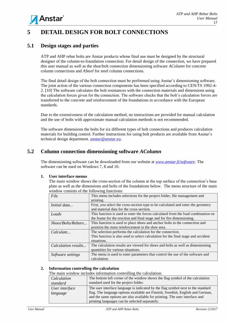
5 DETAIL DESIGN FOR BOLT CONNECTIONS
5.1 Design stages and parties ATP and AHP rebar bolts are Anstar products whose final use must be designed by the structural
designer of the column-to-foundation connection. For detail design of the connection, we have prepared
this user manual as well as the shoe/bolt connection dimensioning software AColumn for concrete
column connections and ASteel for steel column connections.
The final detail design of the bolt connection must be performed using Anstar’s dimensioning software.
The joint action of the various connection components has been specified according to CEN/TS 1992-4-
2. [10] The software calculates the bolt resistances with the connection materials and dimensions using
the calculation forces given for the connection. The software checks that the bolt’s calculation forces are
transferred to the concrete and reinforcement of the foundations in accordance with the European
standards.
Due to the extensiveness of the calculation method, no instructions are provided for manual calculation
and the use of bolts with approximate manual calculation methods is not recommended.
The software dimensions the bolts for six different types of bolt connections and produces calculation
materials for building control. Further instructions for using bolt products are available from Anstar’s
technical design department. [email protected].
5.2 Column connection dimensioning software AColumn
The dimensioning software can be downloaded from our website at www.anstar.fi/software. The
software can be used on Windows 7, 8 and 10.
1. User interface menus
The main window shows the cross-section of the column at the top surface of the connection’s base
plate as well as the dimensions and bolts of the foundations below. The menu structure of the main
window consists of the following functions:
File This menu includes selections for the project folder, file management and
printing.
Initial data... First, you select the cross-section type to be calculated and enter the geometry
and material data for the cross-section.
Loads This function is used to enter the forces calculated from the load combination on
the frame for the erection and final stage and for fire dimensioning.
Shoes/Bolts/Rebars... This function is used to place shoes and anchor bolts in the connection and
position the main reinforcement in the shoe area.
Calculate... The selection performs the calculation for the connection.
This function is also used to select calculation for the final stage and accident
situations.
Calculation results... The calculation results are viewed for shoes and bolts as well as dimensioning
quantities for various situations.
Software settings The menu is used to enter parameters that control the use of the software and
calculation.
2. Information controlling the calculation
The main window includes information controlling the calculation:
Calculation
standard
The bottom left corner of the window shows the flag symbol of the calculation
standard used for the project folder.
User interface
language
The user interface language is indicated by the flag symbol next to the standard
flag. The language options available are Finnish, Swedish, English and German,
and the same options are also available for printing. The user interface and
printing languages can be selected separately.

ATP and AHP Rebar Bolts
User Manual 18
User Manual ATP and AHP Rebar Bolts Revision 12/2017
3. Suitability of bolts for various connection types in foundation structures
Table 10 shows the suitability of ATP and AHP bolts for various foundation structures. The
selection of the application is affected by the bolt length, protective concrete layer requirements
and the edge distance required by the short dowel bolt’s failure cone dimensioning.
Table 10. Suitability of ATP and AHP bolts for various foundation structures
Bolt
Column-to-column
connection
Column-to-foundation
column
connection
Column-to-footing
connection
ATP The bolt is not suitable for
the connection due to the
great edge distance of the
dowel bolt head.
The bolt is not suitable for the
connection due to the great edge
distance of the dowel bolt head.
The bolt is well-suited to a
shallow footing, and the edge
distance of the bolt’s dowel head
is sufficient.
AHP The bolt is well-suited even
to columns of the same size.
The bolt is well-suited if the
foundation column is high
enough. The edge distances are
sufficient.
The bolt is suitable if the bond is
bent to the bottom surface of the
footing or if the footing is high
enough.
Figure 8. Main window with the AHK and AHK-K column shoe connection and AHP bolts
4. Quick review of the calculation results
The main window includes information enabling quick review of the calculation results:
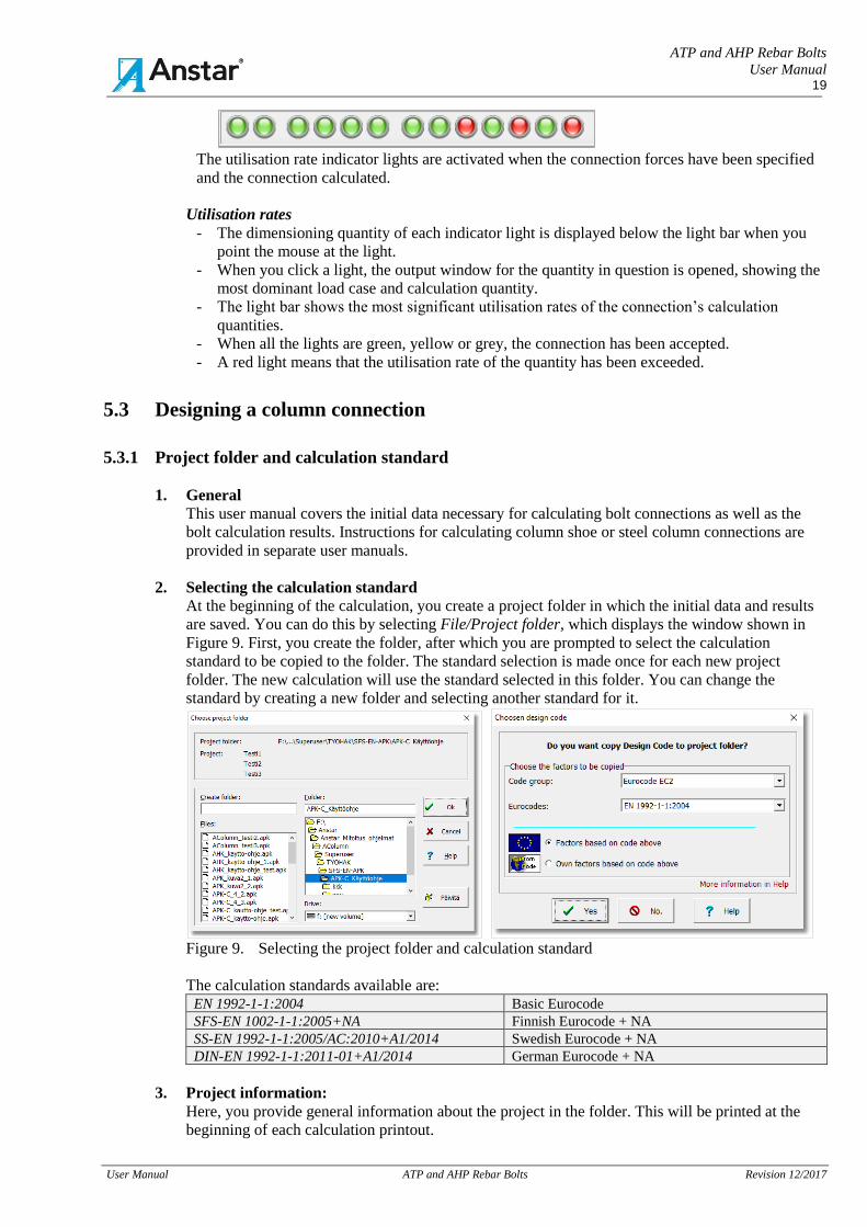
Utilisation rate indicator lights
The bottom bar of the window includes round indicator lights showing the utilisation rates of
various calculation quantities. The colours of the calculation quantities have the following
meanings:
- Green = The utilisation rate is acceptable within the range of 0–0.95.
- Yellow = The utilisation rate is acceptable within the range of 0.951–1.0.
- Red = The utilisation rate is > 1.0, excessive.
- Grey = If the colour is grey, the quantity has not yet been calculated or does not belong
to the dimensioning values for the connection type. If the erection loads are not
provided, the erection is not calculated.
ATP and AHP Rebar Bolts
User Manual 19
User Manual ATP and AHP Rebar Bolts Revision 12/2017
The utilisation rate indicator lights are activated when the connection forces have been specified
and the connection calculated.
Utilisation rates
- The dimensioning quantity of each indicator light is displayed below the light bar when you
point the mouse at the light.
- When you click a light, the output window for the quantity in question is opened, showing the
most dominant load case and calculation quantity.
- The light bar shows the most significant utilisation rates of the connection’s calculation
quantities.
- When all the lights are green, yellow or grey, the connection has been accepted.
- A red light means that the utilisation rate of the quantity has been exceeded.
5.3 Designing a column connection
5.3.1 Project folder and calculation standard
1. General
This user manual covers the initial data necessary for calculating bolt connections as well as the
bolt calculation results. Instructions for calculating column shoe or steel column connections are
provided in separate user manuals.
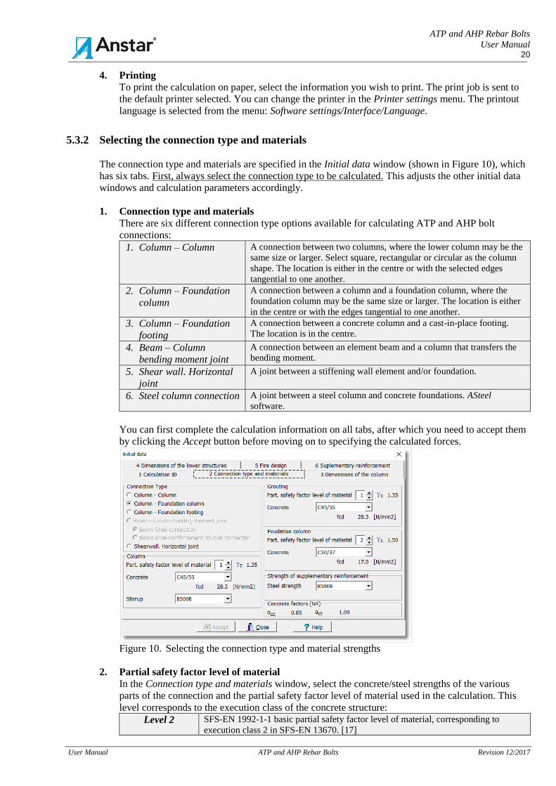
2. Selecting the calculation standard
At the beginning of the calculation, you create a project folder in which the initial data and results
are saved. You can do this by selecting File/Project folder, which displays the window shown in
Figure 9. First, you create the folder, after which you are prompted to select the calculation
standard to be copied to the folder. The standard selection is made once for each new project
folder. The new calculation will use the standard selected in this folder. You can change the
standard by creating a new folder and selecting another standard for it.
Figure 9. Selecting the project folder and calculation standard
The calculation standards available are: EN 1992-1-1:2004 Basic Eurocode
SFS-EN 1002-1-1:2005+NA Finnish Eurocode + NA
SS-EN 1992-1-1:2005/AC:2010+A1/2014 Swedish Eurocode + NA
DIN-EN 1992-1-1:2011-01+A1/2014 German Eurocode + NA
3. Project information:
Here, you provide general information about the project in the folder. This will be printed at the
beginning of each calculation printout.
ATP and AHP Rebar Bolts
User Manual 20
User Manual ATP and AHP Rebar Bolts Revision 12/2017
4. Printing
To print the calculation on paper, select the information you wish to print. The print job is sent to
the default printer selected. You can change the printer in the Printer settings menu. The printout
language is selected from the menu: Software settings/Interface/Language.
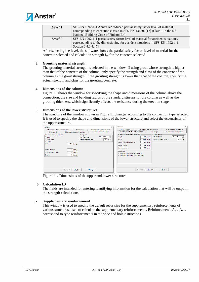
5.3.2 Selecting the connection type and materials
The connection type and materials are specified in the Initial data window (shown in Figure 10), which
has six tabs. First, always select the connection type to be calculated. This adjusts the other initial data
windows and calculation parameters accordingly.
1. Connection type and materials
There are six different connection type options available for calculating ATP and AHP bolt
connections:
1. Column – Column A connection between two columns, where the lower column may be the
same size or larger. Select square, rectangular or circular as the column
shape. The location is either in the centre or with the selected edges
tangential to one another.
2. Column – Foundation
column
A connection between a column and a foundation column, where the
foundation column may be the same size or larger. The location is either
in the centre or with the edges tangential to one another.
3. Column – Foundation
footing
A connection between a concrete column and a cast-in-place footing.
The location is in the centre.
4. Beam – Column
bending moment joint
A connection between an element beam and a column that transfers the
bending moment.
5. Shear wall. Horizontal
joint
A joint between a stiffening wall element and/or foundation.
6. Steel column connection A joint between a steel column and concrete foundations. ASteel
software.
You can first complete the calculation information on all tabs, after which you need to accept them
by clicking the Accept button before moving on to specifying the calculated forces.
Figure 10. Selecting the connection type and material strengths
2. Partial safety factor level of material
In the Connection type and materials window, select the concrete/steel strengths of the various
parts of the connection and the partial safety factor level of material used in the calculation. This
level corresponds to the execution class of the concrete structure:
Level 2 SFS-EN 1992-1-1 basic partial safety factor level of material, corresponding to
execution class 2 in SFS-EN 13670. [17]
ATP and AHP Rebar Bolts
User Manual 21
User Manual ATP and AHP Rebar Bolts Revision 12/2017
Level 1 SFS-EN 1992-1-1 Annex A2 reduced partial safety factor level of material,
corresponding to execution class 3 in SFS-EN 13670. [17] (Class 1 in the old
National Building Code of Finland B4)
Level 0 SFS-EN 1992-1-1 partial safety factor level of material for accident situations,
corresponding to the dimensioning for accident situations in SFS-EN 1992-1-1,
Section 2.4.2.4. [7]
After selecting the level, the software shows the partial safety factor level of material for the
concrete selected and calculation strength fcd for the concrete selected.
3. Grouting material strength
The grouting material strength is selected in the window. If using grout whose strength is higher
than that of the concrete of the column, only specify the strength and class of the concrete of the
column as the grout strength. If the grouting strength is lower than that of the column, specify the
actual strength and class for the grouting concrete.
4. Dimensions of the column
Figure 11 shows the window for specifying the shape and dimensions of the column above the
connection, the size and bending radius of the standard stirrups for the column as well as the
grouting thickness, which significantly affects the resistance during the erection stage.
5. Dimensions of the lower structures
The structure of the window shown in Figure 11 changes according to the connection type selected.
It is used to specify the shape and dimensions of the lower structure and select the eccentricity of
the upper structure.
Figure 11. Dimensions of the upper and lower structures
6. Calculation ID
The fields are intended for entering identifying information for the calculation that will be output in
the strength calculations.
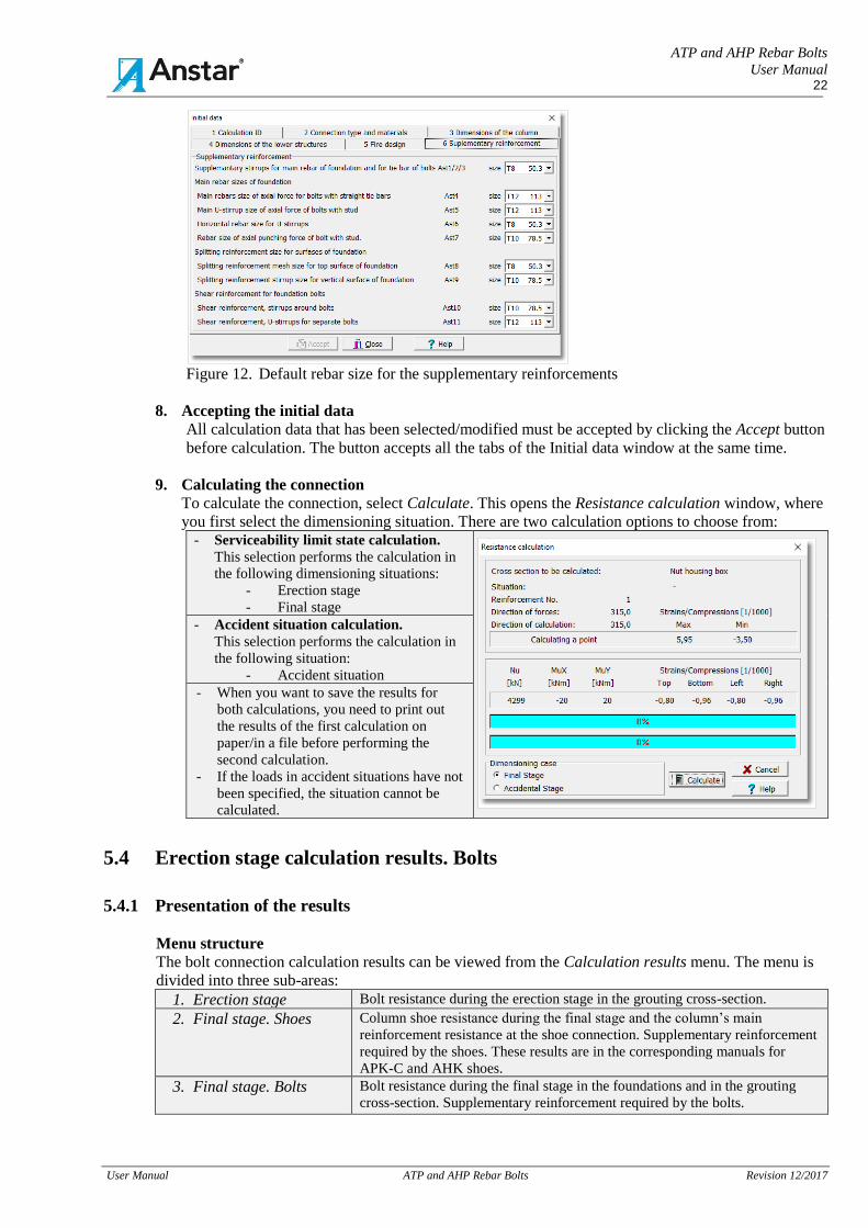
7. Supplementary reinforcement
This window is used to specify the default rebar size for the supplementary reinforcements of
various structures, used to calculate the supplementary reinforcements. Reinforcements Ast3–Ast11
correspond to type reinforcements in the shoe and bolt instructions.
ATP and AHP Rebar Bolts
User Manual 22
User Manual ATP and AHP Rebar Bolts Revision 12/2017
Figure 12. Default rebar size for the supplementary reinforcements
8. Accepting the initial data
All calculation data that has been selected/modified must be accepted by clicking the Accept button
before calculation. The button accepts all the tabs of the Initial data window at the same time.
9. Calculating the connection
To calculate the connection, select Calculate. This opens the Resistance calculation window, where
you first select the dimensioning situation. There are two calculation options to choose from: - Serviceability limit state calculation.
This selection performs the calculation in
the following dimensioning situations:
- Erection stage
- Final stage
- Accident situation calculation.
This selection performs the calculation in
the following situation:
- Accident situation
- When you want to save the results for
both calculations, you need to print out
the results of the first calculation on
paper/in a file before performing the
second calculation.
- If the loads in accident situations have not
been specified, the situation cannot be
calculated.
5.4 Erection stage calculation results. Bolts
5.4.1 Presentation of the results
Menu structure
The bolt connection calculation results can be viewed from the Calculation results menu. The menu is
divided into three sub-areas:
1. Erection stage Bolt resistance during the erection stage in the grouting cross-section.
2. Final stage. Shoes Column shoe resistance during the final stage and the column’s main
reinforcement resistance at the shoe connection. Supplementary reinforcement
required by the shoes. These results are in the corresponding manuals for
APK-C and AHK shoes.
3. Final stage. Bolts
Bolt resistance during the final stage in the foundations and in the grouting
cross-section. Supplementary reinforcement required by the bolts.
ATP and AHP Rebar Bolts
User Manual 23
User Manual ATP and AHP Rebar Bolts Revision 12/2017
Calculation coordinate system
The windows show the strengths and utilisation rates for each calculation quantity by combination case
as well as the calculation parameters. The results are shown in the directions of the main axes and in the
XY direction of skew bending. Skew bending is calculated as a combination of the forces in the
direction of the main axes for the combination in question.
Utilisation rates
The row featuring the utilisation rates has acceptance indicators with the following colour codes:
Green - The utilisation rate of the quantity is 0–0.95.
Yellow - The utilisation rate of the quantity is 0.95–1.00.
Red - The utilisation rate of the quantity is > 1.00.
Grey - The quantity has not been calculated or does not belong to the bolt’s design values.
Maximum
utilisation rate of
the quantity
- Clicking an indicator light opens a window showing the combination case for the
maximum utilisation rate.
- Excess values can be found easily, and also the maximum acceptable utilisation rate
for each quantity and the combination in which it occurs.
Numbering of the structures
After the calculation, numbers will be displayed in the main window at the bolt and shoe bonds and the
column’s main rebars. These numbers will be displayed next to the corresponding part/row in the
printout windows. The information on the printout row can be traced to a structure in the main window.
The numbers will be displayed after the calculation.
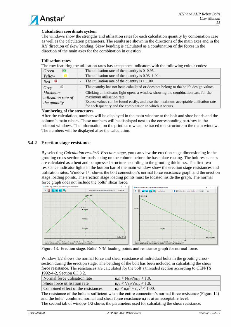
5.4.2 Erection stage resistance
By selecting Calculation results/1 Erection stage, you can view the erection stage dimensioning in the
grouting cross-section for loads acting on the column before the base plate casting. The bolt resistances
are calculated as a bent and compressed structure according to the grouting thickness. The first two
resistance indicator lights in the bottom bar of the main window show the erection stage resistances and
utilisation rates. Window 1/1 shows the bolt connection’s normal force resistance graph and the erection
stage loading points. The erection stage loading points must be located inside the graph. The normal
force graph does not include the bolts’ shear force.
Figure 13. Erection stage. Bolts’ N/M loading points and resistance graph for normal force.
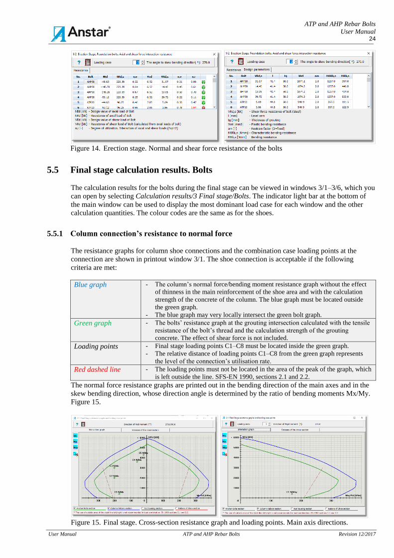
Window 1/2 shows the normal force and shear resistance of individual bolts in the grouting cross-
section during the erection stage. The bending of the bolt has been included in calculating the shear
force resistance. The resistances are calculated for the bolt’s threaded section according to CEN/TS
1992-4-2, Section 6.3.3.2.
Normal force utilisation rate n,n ≤ NEd/NRd,s ≤ 1.0.
Shear force utilisation rate n,v ≤ VEd/VRd,s ≤ 1.0.
Combined effect of the resistances n,i ≤ n,n2 + n,v2 ≤ 1.00.
The resistance of the bolts is sufficient when the entire connection’s normal force resistance (Figure 14)
and the bolts’ combined normal and shear force resistance n,i is at an acceptable level.
The second tab of window 1/2 shows the parameters used for calculating the shear resistance.
ATP and AHP Rebar Bolts
User Manual 24
User Manual ATP and AHP Rebar Bolts Revision 12/2017
Figure 14. Erection stage. Normal and shear force resistance of the bolts
5.5 Final stage calculation results. Bolts
The calculation results for the bolts during the final stage can be viewed in windows 3/1–3/6, which you
can open by selecting Calculation results/3 Final stage/Bolts. The indicator light bar at the bottom of
the main window can be used to display the most dominant load case for each window and the other
calculation quantities. The colour codes are the same as for the shoes.
5.5.1 Column connection’s resistance to normal force
The resistance graphs for column shoe connections and the combination case loading points at the
connection are shown in printout window 3/1. The shoe connection is acceptable if the following
criteria are met:
Blue graph - The column’s normal force/bending moment resistance graph without the effect
of thinness in the main reinforcement of the shoe area and with the calculation
strength of the concrete of the column. The blue graph must be located outside
the green graph.
- The blue graph may very locally intersect the green bolt graph.
Green graph - The bolts’ resistance graph at the grouting intersection calculated with the tensile
resistance of the bolt’s thread and the calculation strength of the grouting
concrete. The effect of shear force is not included.
Loading points - Final stage loading points C1–C8 must be located inside the green graph.
- The relative distance of loading points C1–C8 from the green graph represents
the level of the connection’s utilisation rate.
Red dashed line - The loading points must not be located in the area of the peak of the graph, which
is left outside the line. SFS-EN 1990, sections 2.1 and 2.2.
The normal force resistance graphs are printed out in the bending direction of the main axes and in the
skew bending direction, whose direction angle is determined by the ratio of bending moments Mx/My.
Figure 15.
Figure 15. Final stage. Cross-section resistance graph and loading points. Main axis directions.
ATP and AHP Rebar Bolts
User Manual 25
User Manual ATP and AHP Rebar Bolts Revision 12/2017
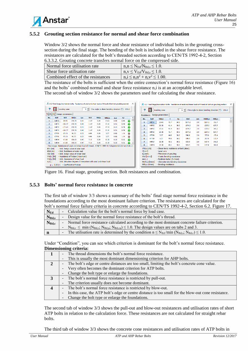
5.5.2 Grouting section resistance for normal and shear force combination
Window 3/2 shows the normal force and shear resistance of individual bolts in the grouting cross-
section during the final stage. The bending of the bolt is included in the shear force resistance. The
resistances are calculated for the bolt’s threaded section according to CEN/TS 1992-4-2, Section
6.3.3.2. Grouting concrete transfers normal force on the compressed side.
Normal force utilisation rate n,n ≤ NEd/NRd,s ≤ 1.0.
Shear force utilisation rate n,v ≤ VEd/VRd,s ≤ 1.0.
Combined effect of the resistances n,i ≤ n,n2 + n,v2 ≤ 1.00.
The resistance of the bolts is sufficient when the entire connection’s normal force resistance (Figure 16)
and the bolts’ combined normal and shear force resistance n,i is at an acceptable level.
The second tab of window 3/2 shows the parameters used for calculating the shear resistance.
Figure 16. Final stage, grouting section. Bolt resistances and combination.
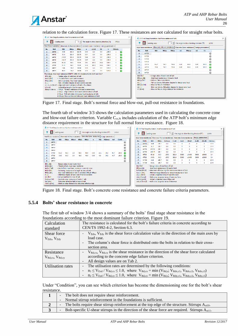
5.5.3 Bolts’ normal force resistance in concrete
The first tab of window 3/3 shows a summary of the bolts’ final stage normal force resistance in the
foundations according to the most dominant failure criterion. The resistances are calculated for the
bolt’s normal force failure criteria in concrete according to CEN/TS 1992-4-2, Section 6.2. Figure 17.
NEd - Calculation value for the bolt’s normal force by load case.
NRd,s - Design value for the normal force resistance of the bolt’s thread.
NRd,c - Normal force resistance calculated according to the most dominant concrete failure criterion.
- NRd,c ≤ min (NRd,c; NRd,p; NRd,cp) ≤ 1.0. The design values are on tabs 2 and 3.
n - The utilisation rate is determined by the condition n ≤ NEd /min (NRd,s; NRd,c) ≤ 1.0.
Under “Condition”, you can see which criterion is dominant for the bolt’s normal force resistance.
Dimensioning criteria:
1 - The thread dimensions the bolt’s normal force resistance.
- This is usually the most dominant dimensioning criterion for AHP bolts.
2 - The bolt’s edge or centre distances are too small, limiting the bolt’s concrete cone value.
- Very often becomes the dominant criterion for ATP bolts.
- Change the bolt type or enlarge the foundations.
3 - The bolt’s normal force resistance is restricted by pull-out.
- The criterion usually does not become dominant.
4 - The bolt’s normal force resistance is restricted by blow-out.
- In this case, the ATP bolt’s edge or centre distance is too small for the blow-out cone resistance.
- Change the bolt type or enlarge the foundations.
The second tab of window 3/3 shows the pull-out and blow-out resistances and utilisation rates of short
ATP bolts in relation to the calculation force. These resistances are not calculated for straight rebar
bolts.
The third tab of window 3/3 shows the concrete cone resistances and utilisation rates of ATP bolts in
ATP and AHP Rebar Bolts
User Manual 26
User Manual ATP and AHP Rebar Bolts Revision 12/2017
relation to the calculation force. Figure 17. These resistances are not calculated for straight rebar bolts.
Figure 17. Final stage. Bolt’s normal force and blow-out, pull-out resistance in foundations.
The fourth tab of window 3/3 shows the calculation parameters used in calculating the concrete cone
and blow-out failure criterion. Variable Ccr,N includes calculation of the ATP bolt’s minimum edge
distance requirement in the structure for full normal force resistance. Figure 18.
Figure 18. Final stage. Bolt’s concrete cone resistance and concrete failure criteria parameters.
5.5.4 Bolts’ shear resistance in concrete
The first tab of window 3/4 shows a summary of the bolts’ final stage shear resistance in the
foundations according to the most dominant failure criterion. Figure 19.
Calculation
standard
The resistance is calculated for the bolt’s failure criteria in concrete according to
CEN/TS 1992-4-2, Section 6.3.
Shear force VEdx, VEdy
- VEdx, VEdy is the shear force calculation value in the direction of the main axes by
load case.
- The column’s shear force is distributed onto the bolts in relation to their cross-
section area.
Resistance VRd,cx, VRd,cy
- VRd,cx, VRd,cy is the shear resistance in the direction of the shear force calculated
according to the concrete edge failure criterion.
- All design values are on Tab 2.
Utilisation rates - The utilisation rates are determined by the following conditions:
- n1 ≤ VExd / VRd,cx ≤ 1.0, where VRd,cx = min (VRd,s; VRdx,c1, VRdx,c2, VRdx,c3)
- n2 ≤ VEyd / VRd,cy ≤ 1.0, where VRd,cy = min (VRd,s; VRdy,c1, VRdy,c2, VRdy,c3)
Under “Condition”, you can see which criterion has become the dimensioning one for the bolt’s shear
resistance.
1 - The bolt does not require shear reinforcement.
- Normal stirrup reinforcement in the foundations is sufficient.
2 - The bolts require shear stirrup reinforcement at the top edge of the structure. Stirrups Ast10.
3 - Bolt-specific U-shear stirrups in the direction of the shear force are required. Stirrups Ast11.
ATP and AHP Rebar Bolts
User Manual 27
User Manual ATP and AHP Rebar Bolts Revision 12/2017
4 - The bolt’s steel shear resistance VRd,s is dominant.
- This usually does not become the dimensioning criterion in concrete.
5 - The bolt is too close to the edge of the structure or another bolt.
- The shear resistance is not sufficient even with U-shear reinforcements.
- Change the bolt size or enlarge the foundation dimensions or change the shear force transfer
method.
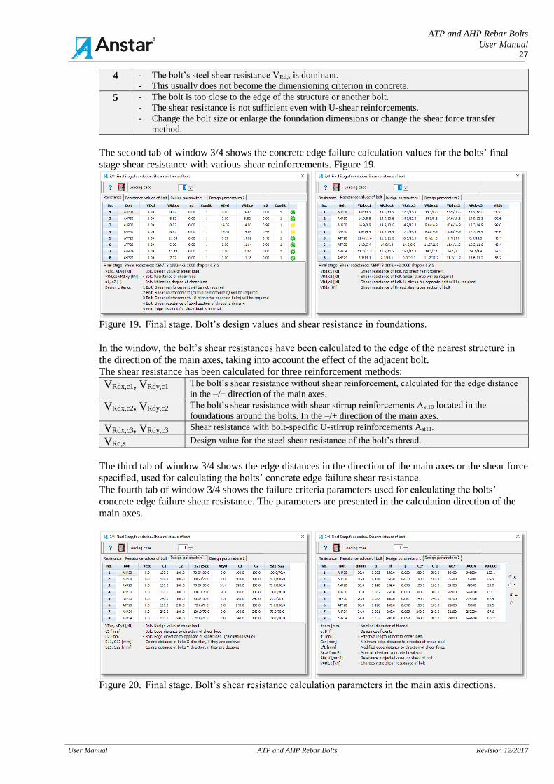
The second tab of window 3/4 shows the concrete edge failure calculation values for the bolts’ final
stage shear resistance with various shear reinforcements. Figure 19.
Figure 19. Final stage. Bolt’s design values and shear resistance in foundations.
In the window, the bolt’s shear resistances have been calculated to the edge of the nearest structure in
the direction of the main axes, taking into account the effect of the adjacent bolt.
The shear resistance has been calculated for three reinforcement methods:
VRdx,c1, VRdy,c1 The bolt’s shear resistance without shear reinforcement, calculated for the edge distance
in the –/+ direction of the main axes.
VRdx,c2, VRdy,c2 The bolt’s shear resistance with shear stirrup reinforcements Ast10 located in the
foundations around the bolts. In the –/+ direction of the main axes.
VRdx,c3, VRdy,c3 Shear resistance with bolt-specific U-stirrup reinforcements Ast11.
VRd,s Design value for the steel shear resistance of the bolt’s thread.
The third tab of window 3/4 shows the edge distances in the direction of the main axes or the shear force
specified, used for calculating the bolts’ concrete edge failure shear resistance.
The fourth tab of window 3/4 shows the failure criteria parameters used for calculating the bolts’
concrete edge failure shear resistance. The parameters are presented in the calculation direction of the
main axes.
Figure 20. Final stage. Bolt’s shear resistance calculation parameters in the main axis directions.
ATP and AHP Rebar Bolts
User Manual 28
User Manual ATP and AHP Rebar Bolts Revision 12/2017
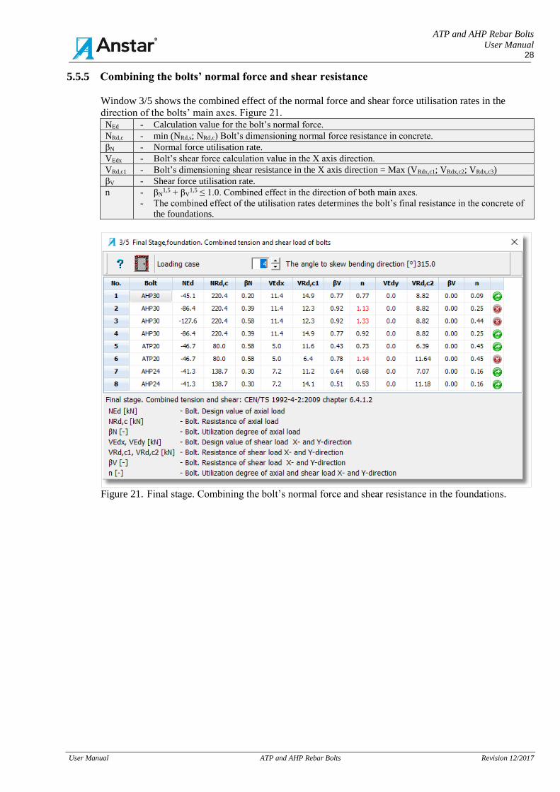
5.5.5 Combining the bolts’ normal force and shear resistance
Window 3/5 shows the combined effect of the normal force and shear force utilisation rates in the
direction of the bolts’ main axes. Figure 21. NEd - Calculation value for the bolt’s normal force.
NRd,c - min (NRd,s; NRd,c) Bolt’s dimensioning normal force resistance in concrete.
βN - Normal force utilisation rate.
VEdx - Bolt’s shear force calculation value in the X axis direction.
VRd,c1 - Bolt’s dimensioning shear resistance in the X axis direction = Max (VRdx,c1; VRdx,c2; VRdx,c3)
βV - Shear force utilisation rate.
n - βN1,5 + βV
1,5 ≤ 1.0. Combined effect in the direction of both main axes.
- The combined effect of the utilisation rates determines the bolt’s final resistance in the concrete of
the foundations.
Figure 21. Final stage. Combining the bolt’s normal force and shear resistance in the foundations.
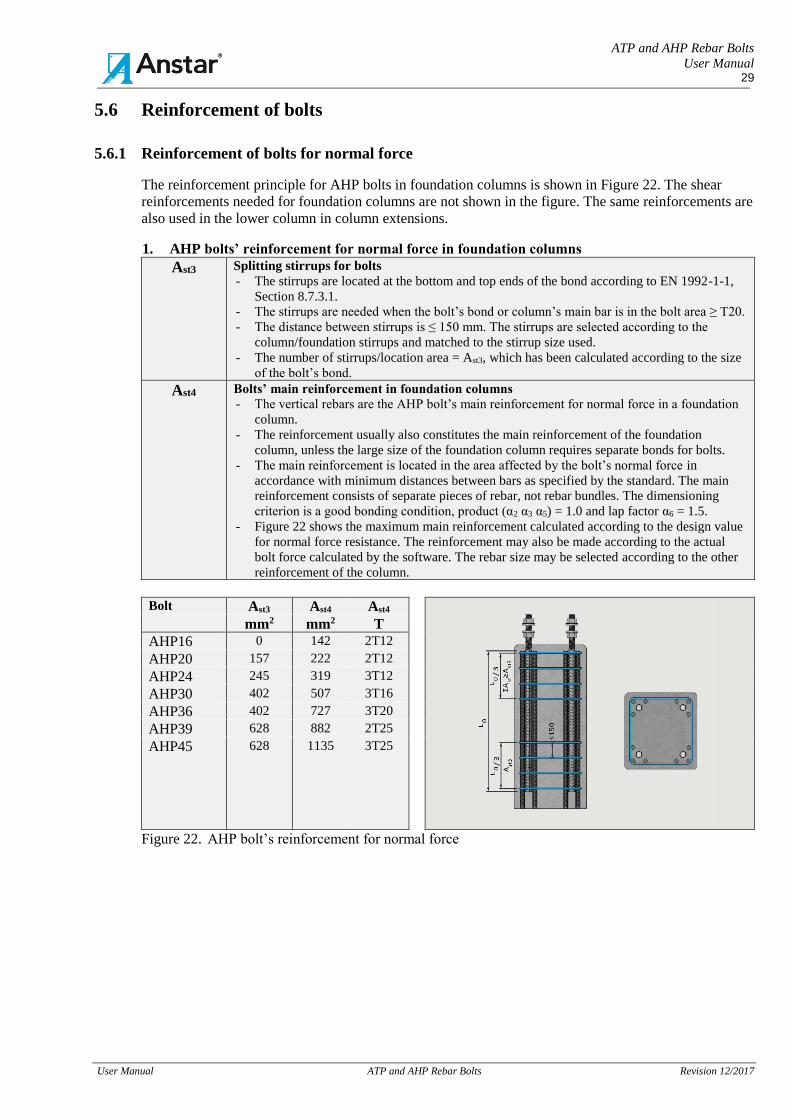
ATP and AHP Rebar Bolts
User Manual 29
User Manual ATP and AHP Rebar Bolts Revision 12/2017
5.6 Reinforcement of bolts
5.6.1 Reinforcement of bolts for normal force
The reinforcement principle for AHP bolts in foundation columns is shown in Figure 22. The shear
reinforcements needed for foundation columns are not shown in the figure. The same reinforcements are
also used in the lower column in column extensions.
1. AHP bolts’ reinforcement for normal force in foundation columns
Ast3 Splitting stirrups for bolts
- The stirrups are located at the bottom and top ends of the bond according to EN 1992-1-1,
Section 8.7.3.1.
- The stirrups are needed when the bolt’s bond or column’s main bar is in the bolt area ≥ T20.
- The distance between stirrups is ≤ 150 mm. The stirrups are selected according to the
column/foundation stirrups and matched to the stirrup size used.
- The number of stirrups/location area = Ast3, which has been calculated according to the size
of the bolt’s bond.
Ast4 Bolts’ main reinforcement in foundation columns
- The vertical rebars are the AHP bolt’s main reinforcement for normal force in a foundation
column.
- The reinforcement usually also constitutes the main reinforcement of the foundation
column, unless the large size of the foundation column requires separate bonds for bolts.
- The main reinforcement is located in the area affected by the bolt’s normal force in
accordance with minimum distances between bars as specified by the standard. The main
reinforcement consists of separate pieces of rebar, not rebar bundles. The dimensioning
criterion is a good bonding condition, product (α2 α3 α5) = 1.0 and lap factor α6 = 1.5.
- Figure 22 shows the maximum main reinforcement calculated according to the design value
for normal force resistance. The reinforcement may also be made according to the actual
bolt force calculated by the software. The rebar size may be selected according to the other
reinforcement of the column.
Bolt Ast3 Ast4 Ast4
mm2 mm2 T
AHP16 0 142 2T12
AHP20 157 222 2T12
AHP24 245 319 3T12
AHP30 402 507 3T16
AHP36 402 727 3T20
AHP39 628 882 2T25
AHP45 628 1135 3T25
Figure 22. AHP bolt’s reinforcement for normal force
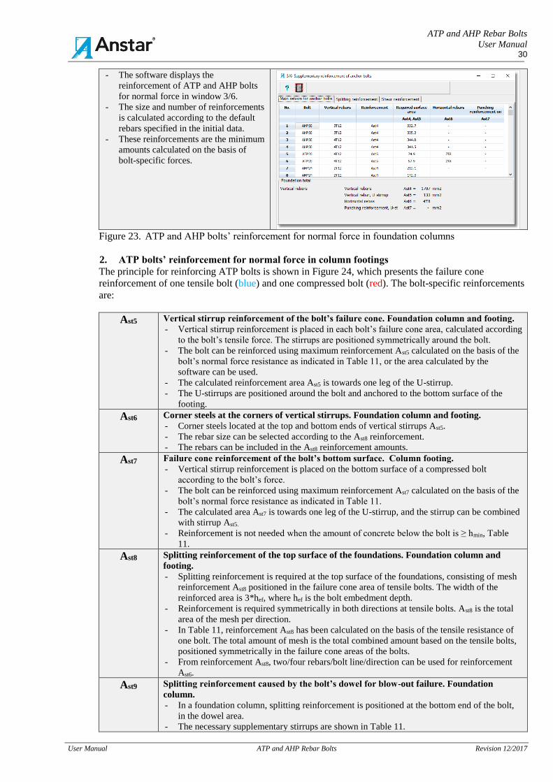
ATP and AHP Rebar Bolts
User Manual 30
User Manual ATP and AHP Rebar Bolts Revision 12/2017
- The software displays the
reinforcement of ATP and AHP bolts
for normal force in window 3/6.
- The size and number of reinforcements
is calculated according to the default
rebars specified in the initial data.
- These reinforcements are the minimum
amounts calculated on the basis of
bolt-specific forces.
Figure 23. ATP and AHP bolts’ reinforcement for normal force in foundation columns
2. ATP bolts’ reinforcement for normal force in column footings
The principle for reinforcing ATP bolts is shown in Figure 24, which presents the failure cone
reinforcement of one tensile bolt (blue) and one compressed bolt (red). The bolt-specific reinforcements
are:
Ast5 Vertical stirrup reinforcement of the bolt’s failure cone. Foundation column and footing.
- Vertical stirrup reinforcement is placed in each bolt’s failure cone area, calculated according
to the bolt’s tensile force. The stirrups are positioned symmetrically around the bolt.
- The bolt can be reinforced using maximum reinforcement Ast5 calculated on the basis of the
bolt’s normal force resistance as indicated in Table 11, or the area calculated by the
software can be used.
- The calculated reinforcement area Ast5 is towards one leg of the U-stirrup.
- The U-stirrups are positioned around the bolt and anchored to the bottom surface of the
footing.
Ast6
Corner steels at the corners of vertical stirrups. Foundation column and footing.
- Corner steels located at the top and bottom ends of vertical stirrups Ast5.
- The rebar size can be selected according to the Ast8 reinforcement.
- The rebars can be included in the Ast8 reinforcement amounts.
Ast7 Failure cone reinforcement of the bolt’s bottom surface. Column footing.
- Vertical stirrup reinforcement is placed on the bottom surface of a compressed bolt
according to the bolt’s force.
- The bolt can be reinforced using maximum reinforcement Ast7 calculated on the basis of the
bolt’s normal force resistance as indicated in Table 11.
- The calculated area Ast7 is towards one leg of the U-stirrup, and the stirrup can be combined
with stirrup Ast5.
- Reinforcement is not needed when the amount of concrete below the bolt is ≥ hmin, Table
11.
Ast8 Splitting reinforcement of the top surface of the foundations. Foundation column and
footing.
- Splitting reinforcement is required at the top surface of the foundations, consisting of mesh
reinforcement Ast8 positioned in the failure cone area of tensile bolts. The width of the
reinforced area is 3*hef, where hef is the bolt embedment depth.
- Reinforcement is required symmetrically in both directions at tensile bolts. Ast8 is the total
area of the mesh per direction.
- In Table 11, reinforcement Ast8 has been calculated on the basis of the tensile resistance of
one bolt. The total amount of mesh is the total combined amount based on the tensile bolts,
positioned symmetrically in the failure cone areas of the bolts.
- From reinforcement Ast8, two/four rebars/bolt line/direction can be used for reinforcement
Ast6.
Ast9 Splitting reinforcement caused by the bolt’s dowel for blow-out failure. Foundation
column.
- In a foundation column, splitting reinforcement is positioned at the bottom end of the bolt,
in the dowel area.
- The necessary supplementary stirrups are shown in Table 11.
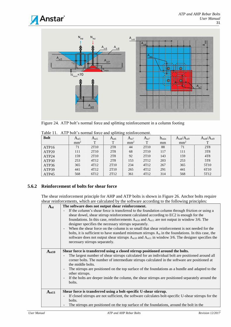
ATP and AHP Rebar Bolts
User Manual 31
User Manual ATP and AHP Rebar Bolts Revision 12/2017
Figure 24. ATP bolt’s normal force and splitting reinforcement in a column footing
Table 11. ATP bolt’s normal force and splitting reinforcement. Bolt Ast5 Ast5 Ast6 Ast7 Ast7 hmin Ast8/Ast9 Ast8/Ast9 mm2 T T mm2 T mm mm2 T
ATP16 71 2T10 2T8 44 2T10 88 71 2T8
ATP20 111 2T10 2T8 68 2T10 117 111 3T8
ATP24 159 2T10 2T8 92 2T10 143 159 4T8
ATP30 253 4T12 2T8 153 2T12 203 253 5T8
ATP36 365 4T12 2T10 234 4T12 267 365 5T10
ATP39 441 4T12 2T10 265 4T12 291 441 6T10
ATP45 568 6T12 2T12 361 4T12 314 568 5T12
5.6.2 Reinforcement of bolts for shear force
The shear reinforcement principle for AHP and ATP bolts is shown in Figure 26. Anchor bolts require
shear reinforcements, which are calculated by the software according to the following principles:
Ast The software does not output shear reinforcement.
- If the column’s shear force is transferred to the foundation column through friction or using a
shear dowel, shear stirrup reinforcement calculated according to EC2 is enough for the
foundations. In this case, reinforcements Ast10 and Ast11 are not output in window 3/6. The
designer specifies the necessary stirrups separately.
- When the shear force on the column is so small that shear reinforcement is not needed for the
bolts, it is sufficient to have standard minimum stirrups Ast in the foundations. In this case, the
software does not output shear stirrups Ast10 and Ast11 in window 3/6. The designer specifies the
necessary stirrups separately.
Ast10 Shear force is transferred using a closed stirrup positioned around the bolts.
- The largest number of shear stirrups calculated for an individual bolt are positioned around all
corner bolts. The number of intermediate stirrups calculated in the software are positioned at
the middle bolts.
- The stirrups are positioned on the top surface of the foundations as a bundle and adapted to the
other stirrups.
- If the bolts are deeper inside the column, the shear stirrups are positioned separately around the
bolts.
Ast11 Shear force is transferred using a bolt-specific U-shear stirrup.
- If closed stirrups are not sufficient, the software calculates bolt-specific U-shear stirrups for the
bolts.
- The stirrups are positioned on the top surface of the foundations, around the bolt in the
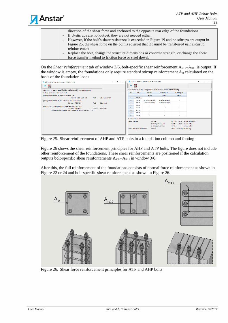
ATP and AHP Rebar Bolts
User Manual 32
User Manual ATP and AHP Rebar Bolts Revision 12/2017
direction of the shear force and anchored to the opposite rear edge of the foundations.
- If U-stirrups are not output, they are not needed either.
- However, if the bolt’s shear resistance is exceeded in Figure 19 and no stirrups are output in
Figure 25, the shear force on the bolt is so great that it cannot be transferred using stirrup
reinforcement.
- Replace the bolt, change the structure dimensions or concrete strength, or change the shear
force transfer method to friction force or steel dowel.
On the Shear reinforcement tab of window 3/6, bolt-specific shear reinforcement Ast10–Ast11 is output. If
the window is empty, the foundations only require standard stirrup reinforcement Ast calculated on the
basis of the foundation loads.
Figure 25. Shear reinforcement of AHP and ATP bolts in a foundation column and footing
Figure 26 shows the shear reinforcement principles for AHP and ATP bolts. The figure does not include
other reinforcement of the foundations. These shear reinforcements are positioned if the calculation
outputs bolt-specific shear reinforcements Ast10–Ast11 in window 3/6.
After this, the full reinforcement of the foundations consists of normal force reinforcement as shown in
Figure 22 or 24 and bolt-specific shear reinforcement as shown in Figure 26.
Figure 26. Shear force reinforcement principles for ATP and AHP bolts
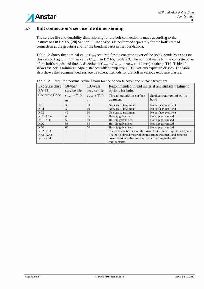
ATP and AHP Rebar Bolts
User Manual 33
User Manual ATP and AHP Rebar Bolts Revision 12/2017
5.7 Bolt connection’s service life dimensioning
The service life and durability dimensioning for the bolt connection is made according to the
instructions in BY 65, [20] Section 2. The analysis is performed separately for the bolt’s thread
connection at the grouting and for the bonding parts in the foundations.
Table 12 shows the nominal value Cnom required for the concrete cover of the bolt’s bonds by exposure
class according to minimum value Cmin,cur in BY 65, Table 2.3. The nominal value for the concrete cover
of the bolt’s bonds and threaded section is Cnom = Cmin,cur + Δcdev (= 10 mm) + stirrup T10. Table 12
shows the bolt’s minimum edge distances with stirrup size T10 in various exposure classes. The table
also shows the recommended surface treatment methods for the bolt in various exposure classes.
Table 12. Required nominal value Cnom for the concrete cover and surface treatment
Exposure class
BY 65
Concrete Code
50-year
service life
Cnom + T10
mm
100-year
service life
Cnom + T10
mm
Recommended thread material and surface treatment
options for bolts
Thread material or surface
treatment
Surface treatment of bolt’s
bond
X0 30 30 No surface treatment No surface treatment
XC1 30 40 No surface treatment No surface treatment
XC2 40 50 No surface treatment No surface treatment
XC3–XC4 45 55 Hot-dip galvanised Hot-dip galvanised
XS1–XD1 50 60 Hot-dip galvanised Hot-dip galvanised
XD2 55 65 Hot-dip galvanised Hot-dip galvanised
XD3 60 70 Hot-dip galvanised Hot-dip galvanised
XS2–XS3
XA1–XA3
XF1–XF4
– – The bolts can be used on the basis of site-specific special analyses.
The bolt’s thread material, bond surface treatment and concrete
cover nominal value are specified according to the site
requirements.
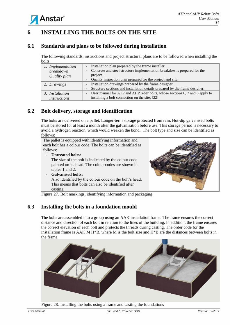
ATP and AHP Rebar Bolts
User Manual 34
User Manual ATP and AHP Rebar Bolts Revision 12/2017
6 INSTALLING THE BOLTS ON THE SITE
6.1 Standards and plans to be followed during installation
The following standards, instructions and project structural plans are to be followed when installing the
bolts.
1. Implementation
breakdown
Quality plan
- Installation plan prepared by the frame installer.
- Concrete and steel structure implementation breakdowns prepared for the
project.
- Quality inspection plan prepared for the project and site.
2. Drawings - Installation drawings prepared by the frame designer.
- Structure sections and installation details prepared by the frame designer.
3. Installation
instructions
- User manual for ATP and AHP rebar bolts, whose sections 6, 7 and 8 apply to
installing a bolt connection on the site. [22]
6.2 Bolt delivery, storage and identification
The bolts are delivered on a pallet. Longer-term storage protected from rain. Hot-dip galvanised bolts
must be stored for at least a month after the galvanisation before use. This storage period is necessary to
avoid a hydrogen reaction, which would weaken the bond. The bolt type and size can be identified as
follows:
The pallet is equipped with identifying information and
each bolt has a colour code. The bolts can be identified as
follows:
- Untreated bolts:
The size of the bolt is indicated by the colour code
painted on its head. The colour codes are shown in
tables 1 and 2.
- Galvanised bolts:
Also identified by the colour code on the bolt’s head.
This means that bolts can also be identified after
casting.
Figure 27. Bolt markings, identifying information and packaging
6.3 Installing the bolts in a foundation mould The bolts are assembled into a group using an AAK installation frame. The frame ensures the correct
distance and direction of each bolt in relation to the lines of the building. In addition, the frame ensures
the correct elevation of each bolt and protects the threads during casting. The order code for the
installation frame is AAK M H*B, where M is the bolt size and H*B are the distances between bolts in
the frame.
Figure 28. Installing the bolts using a frame and casting the foundations
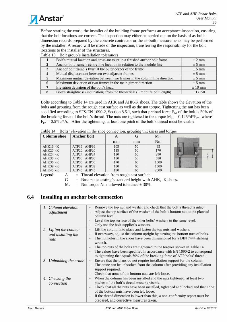
ATP and AHP Rebar Bolts
User Manual 35
User Manual ATP and AHP Rebar Bolts Revision 12/2017
Before starting the work, the installer of the building frame performs an acceptance inspection, ensuring
that the bolt locations are correct. The inspection may either be carried out on the basis of as-built
dimension records prepared by the concrete contractor or the as-built measurements may be performed
by the installer. A record will be made of the inspection, transferring the responsibility for the bolt
locations to the installer of the structures.
Table 13. Bolt group’s installation tolerances 1 Bolt’s mutual location and cross-measure in a finished anchor bolt frame ± 2 mm
2 Anchor bolt frame’s centre line location in relation to the module line ± 5 mm
3 Anchor bolt frame’s twist at the outer corner of the frame ± 5 mm
4 Mutual displacement between two adjacent frames ± 5 mm
5 Maximum mutual deviation between two frames in the column line direction ± 5 mm
6 Maximum deviation of two frames in the main girder direction ± 5 mm
7 Elevation deviation of the bolt’s head ± 10 mm
8 Bolt’s straightness (inclination) from the theoretical (L = entire bolt length) ± L/150
Bolts according to Table 14 are used in AHK and AHK-K shoes. The table shows the elevation of the
bolts and grouting from the rough cast surface as well as the nut torque. Tightening the nut has been
specified according to SFS-EN 1090-2, Section 8.5.1, such that preload force Fc,p of the bolt is 50% of
the breaking force of the bolt’s thread. The nuts are tightened to the torque Mr,1 = 0.125*d*Fp,c, where
Fp,c = 0.5*fub*As. After the tightening, at least one pitch of the bolt’s thread must be visible.
Table 14. Bolts’ elevation in the shoe connection, grouting thickness and torque
Column shoe Anchor bolt A G Mr,1 Note:
mm mm Nm AHK16, -K ATP16 AHP16 105 50 85
AHK20, -K ATP20 AHP20 115 50 170
AHK24, -K ATP24 AHP24 130 50 290
AHK30, -K ATP30 AHP30 150 50 580
AHK36, -K ATP36 AHP36 170 60 1000
AHK39, -K ATP39 AHP39 180 60 1300
AHK45, -K ATP45 AHP45 190 65 2000
Legend: A = Thread elevation from rough cast surface.
G = Base plate casting’s standard height with AHK, -K shoes.
Mv = Nut torque Nm, allowed tolerance ± 30%.
6.4 Installing an anchor bolt connection
1. Column elevation
adjustment
- Remove the top nut and washer and check that the bolt’s thread is intact.
- Adjust the top surface of the washer of the bolt’s bottom nut to the planned
column level.
- Level the top surface of the other bolts’ washers to the same level.
- Only use the bolt supplier’s washers.
2. Lifting the column
and installing the
nuts
- Lift the column into place and fasten the top nuts and washers.
- If necessary, adjust the column upright by turning the bottom nuts of bolts.
- The nut holes in the shoes have been dimensioned for a DIN 7444 striking
wrench.
- The top nuts of the bolts are tightened to the torques shown in Table 14.
- The values have been specified in accordance with EN 1090-2 to correspond
to tightening that equals 50% of the breaking force of ATP bolts’ thread.
3. Unhooking the crane - Ensure that the plans do not require installation support for the column.
- The crane can be unhooked from the column after providing any installation
support required.
- Check that none of the bottom nuts are left loose.
4. Checking the
connection
- When the column has been installed and the nuts tightened, at least two
pitches of the bolt’s thread must be visible.
- Check that all the nuts have been installed, tightened and locked and that none
of the bottom nuts have been left loose.
- If the thread dimension is lower than this, a non-conformity report must be
prepared, and corrective measures taken.
ATP and AHP Rebar Bolts
User Manual 36
User Manual ATP and AHP Rebar Bolts Revision 12/2017
5. Performing the
grouting
- Check the plans to confirm the time at which the grouting is to be performed
and perform the grouting.
The following methods can be used for locking the (top) nuts: A method suitable for the project must be
selected in the structural plans.
1. Locking the bolt’s
thread to the nut
- Tighten the top nut to the torque specified in Table 14 and hit the bolt’s
thread at the root of the nut and thread to break it.
- If necessary, the torque value can be changed by entering a new percentage
in the formula Fp,c = 0.5*fub*Asj instead of the value 0.5 for the preload
force required.
2. Pretensioning and
concrete casting
- Tighten the top nut to the torque specified in Table 14. For locking the nut,
it is enough to cast concrete in the connection around the bolt.
3. Double nut - When dynamic forces are acting, a double nut is used for locking when no
concrete is cast in connection or when it must be possible to remove later.
6.5 Corrective measures allowed for bolts on the site
The structures of the bolt connection must not be modified without the designer’s and/or bolt
manufacturer’s permission. The following measures are allowed on the installation site. A non-
conformity report must be prepared for each change, and the changes must be documented in the
project’s quality documentation.
1. Allowable
corrective
measure
- If necessary due to installation space requirements, the rebar bond of AHP bolts may
be bent (= 10–50 mm) on the site. However, the bend must not reach the bolt’s
threaded section.
- Foundation reinforcements may be welded to the bolt’s bond, if spot welds are used
and the purpose is to fasten the bolt to the mould during the installation.
- Load-bearing joints must not be welded to the bolt’s bond.
- If the washer touches the shoe housing or steel column profile, some material can be
removed from that part of the washer such that the washer sits suitably tightly
against the top surface of the base plate.
- The washer must not be left in a slanted position.
- When a bolt is installed in a slanted position, the nut must not be left in a slanted
position such that it touches the washer on one side only.
- For such cases, an oblique washer is made that can be installed between the nut and a
standard washer to provide the nut with an even contact surface against the washer.
- Standard washers may be added to the connection, if necessary, provided that the
bolt manufacturer’s washer is kept lowermost.
The following corrective measures are not allowed. Changes require a separate non-conformity plan and
the designer’s or bolt manufacturer’s approval.
2. Non-allowable
corrective
measure
- The bolt’s threaded section must not be bent or heated.
- No other force transfer structures may be welded to the bolt.
- A dowel bolt’s bond must not be bent.
- The bolt and its bonds must not be cut and welded to a new location.
- The bolt must not be welded to the base plate of a shoe or steel column.
- The bolt’s washer must be supplied by the bolt manufacturer.
- The washer must not be replaced.
- The nut may never have installed without the bolt’s own washer.
- If the hole in the column’s base plate has been reamed, the washer must be replaced
with a larger one.
- In this case, it is usually necessary to make a special washer.
- The nut of a hot-dip galvanised bolt must not be replaced with a nut based on another
standard.
- A hot-dip galvanised bolt requires a hot-dip galvanised, oversized M8 nut in
accordance with the DIN 934 standard.
- When the nut has been tightened into place, at least two pitches of the bolt’s thread
must be visible.
- If the thread dimension is lower than this, a non-conformity report must be prepared,
and corrective measures approved by the structural designer.
ATP and AHP Rebar Bolts
User Manual 37
User Manual ATP and AHP Rebar Bolts Revision 12/2017
7 SAFETY MEASURES
7.1 Information for preparing work safety instructions for the site
Appointed by the developer, the project’s work safety coordinator is responsible for ensuring work
safety during the building work. When preparing work safety instructions for the project, the following
must be taken into account in anchor bolt connection installations:
1. Installation - Columns are installed by following the working order in the contractor’s installation
plan and the requirement for frame stability during erection determined by the
designer.
- The falling of the column and incorrect loading of the bolt connection during
installation must be prevented by the following measures:
- The column is lifted using lifting lugs/equipment.
- The column must not be moved or lifted from the shoe bolt hole.
- During lifting, the shoe base plate must not hit/rest on the ground or another fixed
structure.
- The lifting equipment is unhooked from the column when the column is in place,
fastened to all bolts and provided with installation support in accordance with the
plans.
- The bolts must not be loaded in ways and with loads deviating from the plan.
2. Stability - The column must never be left standing without fastening it to the bolts with all nuts.
- The frame stability under exceptional natural loads must be ensured at the end of the
shift.
- The overall stability of a partially installed frame must be ensured.
3. Structure - The time at which the shoe connection is to be grouted must be specified in the
installation plan.
- Installation of the upper frame must not be continued before the grout has hardened.
- The grouting concrete is part of the load-bearing structure of the connection, so the
materials and work methods must be selected such that the grout cannot freeze.
- Any installation supports used for the column are removed after the grout in the
connection has hardened.
7.2 Commissioning a bolt connection during construction
The bolt connection is designed for erection stage loads and final stage loads for the frame. There are
significant differences in the connection’s loading capacity between these two stages. The bolt
connection will only reach the final stage load-bearing capacity when the connection’s grouting
concrete has reached the design strength. Until then, the column connection and its loading capacity
must be reviewed using the erection stage resistance values.
The time at which grouting is to be performed is specified in the installation plan. The grouting must not
be postponed, and the column commissioning permit required for continuing the installation of the
upper structures and for additional loading of the column is determined by means of a review.
ATP and AHP Rebar Bolts
User Manual 38
User Manual ATP and AHP Rebar Bolts Revision 12/2017
8 INSTALLATION QUALITY CONTROL
8.1 Instructions for monitoring column installations
Installation quality control for column connections is carried out in accordance with the quality control
plan prepared for the project and site. The structural and dimensional inspections specified in the
implementation breakdown are performed on the building frame. The instructions to be followed are in
SFS-EN 13670 for the requirements for concrete structures and in SFS-EN 1090-2 for the steel frame.
An inspection report is prepared for the frame’s quality control and dimensional inspections and saved
in the project’s quality documentation. The following inspection measures are performed for bolt
connections:
1. Before column
installation
- Ensure that the bolts are not damaged.
- Following the installation plan regarding the installation order of the elements.
- Need for supporting the columns during installation.
- Checking the elevation of the bottom ends of the columns and the bolts.
2. After column
installation,
before
grouting
- Check that the column connection has been installed at the elevation specified in the
plans.
- Ensure that the correct washers have been used and the nuts have been tightened to
the torque specified.
- Ensure that two pitches of the bolt’s thread are visible from the nut.
- Ensure that the strength of the grouting concrete is in accordance with the plans.
3. After grouting
the connection
- Check that the nut holes and joint grouting have been made appropriately and with
the concrete strength according to the plans.
- Ensure that all the nut holes and the grouting joint have been filled with concrete.
- Ensure that the grouting of the connection meets the fire protection requirements for
the connection.
4. Deviations If the frame installer deviates from the approved plans and documents in any of the
following tasks:
- quality control
- performing the installation work, lifting and transfers
- installation materials
- structure tolerances and dimensional inspection of the frame
- required inspections and their documentation,
the installer is obliged to start documenting the non-conformity upon observing the
deviation from the plan and to have the client approve the resulting measures. Non-
conformity reports are saved in the project’s quality documentation.
8.2 Final documentation of installation quality control
When the job has been accepted, the frame installer is required to deliver the inspection and quality
control documentation created during the installation work to the client.
1. Readiness
inspection
records
- As-built dimension record for the bolts.
- Loading capacity and commissioning inspection of the columns after grouting.
2. Non-conformity
reports
- Any non-conformity reports prepared during the installation of the bolt connection
are handed over.
3. Product
approval as-
built
- CE marking certificates or corresponding product approval information for
materials purchased for the site.
- As-built documentation for changes made to the structure.
ATP and AHP Rebar Bolts
User Manual 39
User Manual ATP and AHP Rebar Bolts Revision 12/2017
REFERENCES [1] SFS-EN 1090-1 Execution of steel structures and aluminium structures. Part 1: Requirements for conformity assessment of structural
components.
[2] SFS-EN 1090-2 Execution of steel structures and aluminium structures. Part 2: Technical requirements for steel structures. [3] SFS-EN ISO 3834 Quality requirements for fusion welding of metallic materials. Part 1: Criteria for the selection of the appropriate level of
quality requirements, and parts 2–5
[4] SFS-EN 1990, Eurocode. Basis of structural design [5] SFS-EN 1991-1, Eurocode 1. Actions on structures, parts 1–7
[6] SFS-EN 1992-1-1, Eurocode 2. Design of concrete structures. Part 1-1: General rules and rules for buildings.
[7] SFS-EN 1992-1-2, Eurocode 2. Design of concrete structures. Part 1-2: General rules. Structural fire design. [8] SFS-EN 1993-1, Eurocode 3. Design of steel structures. Part 1-1: General rules and rules for buildings. Parts 1–10
[9] CEN/TS 1992-4-1 Design of fasteners in concrete – Part 4-1: General
[10] CEN/TS 1992-4-2 Design of fasteners use in concrete – Part 4-2: Headed Fasteners [11] SFS-EN ISO 5817, Welding. Fusion-welded joints in steel, nickel, titanium and their alloys. Weld classes.
[12] SFS-EN ISO 12944, Paints and varnishes. Corrosion protection of steel structures by protective paint systems. Part 1: General, and parts 2–7.
[13] SFS-EN ISO 1461, Hot dip galvanized coatings on fabricated iron and steel articles. Specifications and test methods. [14] SFS-EN 10025, Hot rolled products of structural steels. Part 1: General technical delivery conditions.
[15] SFS-EN ISO 1684 Fasteners. Hot dip galvanized coating
[16] SFS-EN 17760-1 Welding. Welding of reinforcing steel. Part 1: Load-bearing welded joints. [17] SFS-EN 13670 Execution of concrete structures
[18] SFS-EN 13325 Precast concrete products. Column and beam elements. [19] SFS-EN 13369 Common rules for precast concrete products.
[20] BY 65 Concrete Codes 2016
[21] Anstar Oy. AHK column shoes user manual) [22] Anstar Oy. ATP and AHP rebar bolts user manual [23] RIL 201-4-2017 Ensuring the failure tolerance of structures in accident situations).
LIST OF TABLES Table 1. ATP bolt dimensions .............................................................................................................................................................................. 6 Table 2. AHP bolt dimensions ............................................................................................................................................................................. 7 Table 3. Minimum lap length l0,min of AHP bolts according to SFS-EN 1992-1-1 ............................................................................................... 7 Table 4. Bolt manufacturing programme and user manuals................................................................................................................................ 8 Table 5. Normal force resistance of ATP and AHP bolts during operation and accidents ................................................................................ 10 Table 6. Normal force resistance failure criteria for ATP and AHP bolts ......................................................................................................... 10 Table 7. Minimum edge and centre distances of AHP and ATP bolts for normal force. C25/30 ....................................................................... 10 Table 8. Design values for the shear resistance of ATP and AHP bolts, final stage, concrete C25/30 .............................................................. 11 Table 9. Shear resistance failure criteria for ATP and AHP bolts in foundations ............................................................................................. 12 Table 10. Suitability of ATP and AHP bolts for various foundation structures ................................................................................................... 18 Table 11. ATP bolt’s normal force and splitting reinforcement. ......................................................................................................................... 31 Table 12. Required nominal value Cnom for the concrete cover and surface treatment ..................................................................................... 33 Table 13. Bolt group’s installation tolerances .................................................................................................................................................... 35 Table 14. Bolts’ elevation in the shoe connection, grouting thickness and torque .............................................................................................. 35
PICTURES Figure 1. ATP bolt with dowel anchor and AHP bolt with rebar bond ................................................................................................................. 4 Figure 2. ATP and AHP bolt connections in concrete columns with AHK shoes .................................................................................................. 4 Figure 3. ATP and AHP bolt connections in composite and steel columns ........................................................................................................... 5 Figure 4. ATP and AHP bolts in a shear wall shoe connection ............................................................................................................................ 5 Figure 5. ATP and AHP bolts in equipment foundations, principle drawing ........................................................................................................ 5 Figure 6. ATP bolt structure ................................................................................................................................................................................. 6 Figure 7. AHP bolt structure ................................................................................................................................................................................ 7 Figure 8. Main window with the AHK and AHK-K column shoe connection and AHP bolts .............................................................................. 18 Figure 9. Selecting the project folder and calculation standard ......................................................................................................................... 19 Figure 10. Selecting the connection type and material strengths .......................................................................................................................... 20 Figure 11. Dimensions of the upper and lower structures .................................................................................................................................... 21 Figure 12. Default rebar size for the supplementary reinforcements .................................................................................................................... 22 Figure 13. Erection stage. Bolts’ N/M loading points and resistance graph for normal force. ............................................................................. 23 Figure 14. Erection stage. Normal and shear force resistance of the bolts ........................................................................................................... 24 Figure 15. Final stage. Cross-section resistance graph and loading points. Main axis directions. ...................................................................... 24 Figure 16. Final stage, grouting section. Bolt resistances and combination. ........................................................................................................ 25 Figure 17. Final stage. Bolt’s normal force and blow-out, pull-out resistance in foundations. ............................................................................ 26 Figure 18. Final stage. Bolt’s concrete cone resistance and concrete failure criteria parameters. ...................................................................... 26 Figure 19. Final stage. Bolt’s design values and shear resistance in foundations. ............................................................................................... 27 Figure 20. Final stage. Bolt’s shear resistance calculation parameters in the main axis directions..................................................................... 27 Figure 21. Final stage. Combining the bolt’s normal force and shear resistance in the foundations. .................................................................. 28 Figure 22. AHP bolt’s reinforcement for normal force ......................................................................................................................................... 29 Figure 23. ATP and AHP bolts’ reinforcement for normal force in foundation columns ...................................................................................... 30 Figure 24. ATP bolt’s normal force and splitting reinforcement in a column footing ........................................................................................... 31 Figure 25. Shear reinforcement of AHP and ATP bolts in a foundation column and footing ................................................................................ 32 Figure 26. Shear force reinforcement principles for ATP and AHP bolts ............................................................................................................. 32 Figure 27. Bolt markings, identifying information and packaging ........................................................................................................................ 34 Figure 28. Installing the bolts using a frame and casting the foundations ............................................................................................................ 34
ATP and AHP Rebar Bolts
User Manual 40
User Manual ATP and AHP Rebar Bolts Revision 12/2017