Embed Size (px)
Citation preview

Atom ID0406-6.5 User Manual
August 2018
Version 1.5

ii
About This Document This document is intended for installers and users of the Baicells Atom ID04/ID06-6.5 user equipment (UE). The information covers how to install, set up, and use the indoor UE for broadband wireless access to Long-Term Evolution (LTE) carrier networks.
Copyright Notice Baicells Technologies, Inc., copyrights the information in this document. No part of this document may be reproduced in any form or means without the prior written consent of Baicells Technologies, Inc.
Disclaimer The information in this document is subject to change at any time without notice. For more information, please consult with a Baicells technical engineer or the support team. Refer to the “Contact Us” section below.
Revision Record Date Version Description SMEs/Contributors Writer/Editor
27-Aug-18 V1.5 Updated GUI screen shots based on BaiCPE_V100R001C01B005SPC009 and BaiCE_AP_2.1.4_NA
Sharon Redfoot
21-Feb-18 V1.4 Removed Atom ID04-3.5; updated specs
Katie Heyl Cameron Kilton
Sharon Redfoot
11-Dec-17 V1.3 Updates from engineering
Yang Yanan Sharon Redfoot
11-Dec-17 V1.2 Added ID06-6.5 Yang Yanan Sharon Redfoot
7-Dec-17 V1.1 Draft-2 for review Yang Yanan Cameron Kilton Rick Harnish
Sharon Redfoot
14-Sep-17 V1.0 Initial draft Yang Yanan Cameron Kilton
Sharon Redfoot

iii
Contact Us Baicells Technologies Co., Ltd.
China North America Address: 3F, Bldg. A, No. 1 Kai Tuo Rd, Haidian Dist, Beijing, China
Address: 555 Republic Dr., #200, Plano, TX 75074, USA
Phone: +86-10-62607100 Phone: +1-888-502-5585
E-mail: [email protected] Email: [email protected] or [email protected]
Website: www.Baicells.com Website: https://na.Baicells.com
iv
Table of Contents 1. INTRODUCTION ......................................................................................................................... 1
2. PARTS LIST ................................................................................................................................. 3
3. DESCRIPTION ............................................................................................................................. 4
4. INSTALLATION ............................................................................................................................ 6
5. BASIC CONFIGURATION ............................................................................................................. 8
APPENDIX A: TECHNICAL SPECIFICATIONS ........................................................................................ 14
BASIC SPECIFICATIONS ........................................................................................................................... 14 RF SPECIFICATIONS ................................................................................................................................ 14 WI-FI SPECIFICATIONS ........................................................................................................................... 15 SW SPECIFICATIONS .............................................................................................................................. 16 ENVIRONMENTAL SPECIFICATIONS............................................................................................................... 17 VOICE SPECIFICATIONS (ATOM ID06-6.5 ONLY) ........................................................................................... 17 GLOBAL PART NUMBERS .......................................................................................................................... 17
APPENDIX B: CLOUDKEY................................................................................................................... 18
APPENDIX C: FAQS ........................................................................................................................... 19
List of Figures FIGURE 1-1: BAICELLS BROADBAND WIRELESS ACCESS SYSTEM .............................................................................. 1 FIGURE 3-1: DIMENSIONS ............................................................................................................................... 4 FIGURE 3-2: LEDS AND INTERFACES .................................................................................................................. 4 FIGURE 4-1: USIM ....................................................................................................................................... 6 FIGURE 4-2: CABLES ...................................................................................................................................... 6 FIGURE 4-3: LABEL ........................................................................................................................................ 7 FIGURE 5-1: LOGIN........................................................................................................................................ 8 FIGURE 5-2: MAIN MENU .............................................................................................................................. 9 FIGURE 5-3: CHANGE PASSWORD..................................................................................................................... 9 FIGURE 5-4: NETWORK MODE ...................................................................................................................... 10 FIGURE 5-5: CONNECTION METHOD ............................................................................................................... 10 FIGURE 5-6: SCAN METHOD ......................................................................................................................... 11 FIGURE 5-7: FREQUENCY LOCK ...................................................................................................................... 11 FIGURE 5-8: PCI LOCK ................................................................................................................................. 12 FIGURE 5-9: APN MANAGEMENT .................................................................................................................. 12

v
List of Tables TABLE 2-1: PARTS ......................................................................................................................................... 3 TABLE 3-1: LEDS .......................................................................................................................................... 5 TABLE 3-2: INTERFACES .................................................................................................................................. 5 TABLE 4-1: LTE SIGNAL STRENGTH ................................................................................................................... 7 TABLE 5-1: APN MANAGEMENT SETTINGS ...................................................................................................... 13

1
1. Introduction The Baicells Atom ID04/D06-6.5 indoor user equipment (UE) is part of the Baicells broadband wireless access system that integrates with carrier networks based on Long-Term Evolution (LTE) technology. The Baicells system allows telecom operators, service providers, and enterprises to bring broadband data and voice services to customers or employees, even in challenging environments such as rural locations. The indoor UE serves as a gateway between the user’s computers or other smart devices and the carrier network by communicating wirelessly with the operator’s LTE eNodeB’s (eNB) at cell sites located in the region (Figure 1-1). The eNBs communicate with the carrier network, providing the user with internet access. The user-friendly, plug-and-play design behind the Atom UE makes it quick and easy to install, configure, and use. And because it is carrier-grade equipment, the UE is built for endurance and the ability to adapt newer LTE technologies as they evolve. Figure 1-1: Baicells Broadband Wireless Access System

2
Some of the key features of the Atom indoor UE include the following. Exact specifications vary by model: (Refer to Appendix A for details.)
• Supports standard LTE network FDD and TDD network modes: o FDD band 7 o TDD bands 34, 38, 40, 41, 42, 43, and 48
• Complies with 3GPP standards o Atom ID04-6.5: Release 9 CAT 4 o Atom ID06-6.5: Release 10 CAT 6/7
• Ethernet interface: o Atom ID04-6.5: 10/100 Mbps Ethernet o Atom ID06-6.5: 10/100/1000 Mbps Ethernet
• Atom ID06-6.5 provides VoIP communications, with fax and point-of-sale (POS) equipment connectivity using RJ-11 interface
• IEEE 802.11b/g/n Wi-Fi, 2.4 GHz • Cell lock, SIM lock, and Pin lock supported • Local and Web based user GUIs; network management through Baicells CloudCore
Operations Management Console (OMC) • User-friendly LED indicators

3
2. Parts List Refer to Table 2-1 for a list of the components that you should receive with the Baicells Atom ID04/06-6.5. You will need standard tools to install the device.
Table 2-1: Parts
Item Quantity Picture Atom ID04/06-6.5 unit 1
DC-5V Power Adaptor 1
RJ-45 Ethernet Cable 1
User Manual 1 -

4
3. Description The Baicells Atom indoor user equipment (UE) is a small, standards-based device designed to connect seamlessly to the operator’s standard LTE eNB operating on the same band. Different UE models support different frequencies. Refer to Figure 3-1 and the technical details in Appendix A.
Figure 3-1: Dimensions
In addition to LED indicators on the front and back of the units, there are various interfaces on the top and back (Figure 3-2). The LEDs are described in Table 3-1, and the interfaces are explained in Table 3-2.
Figure 3-2: LEDs and Interfaces
5
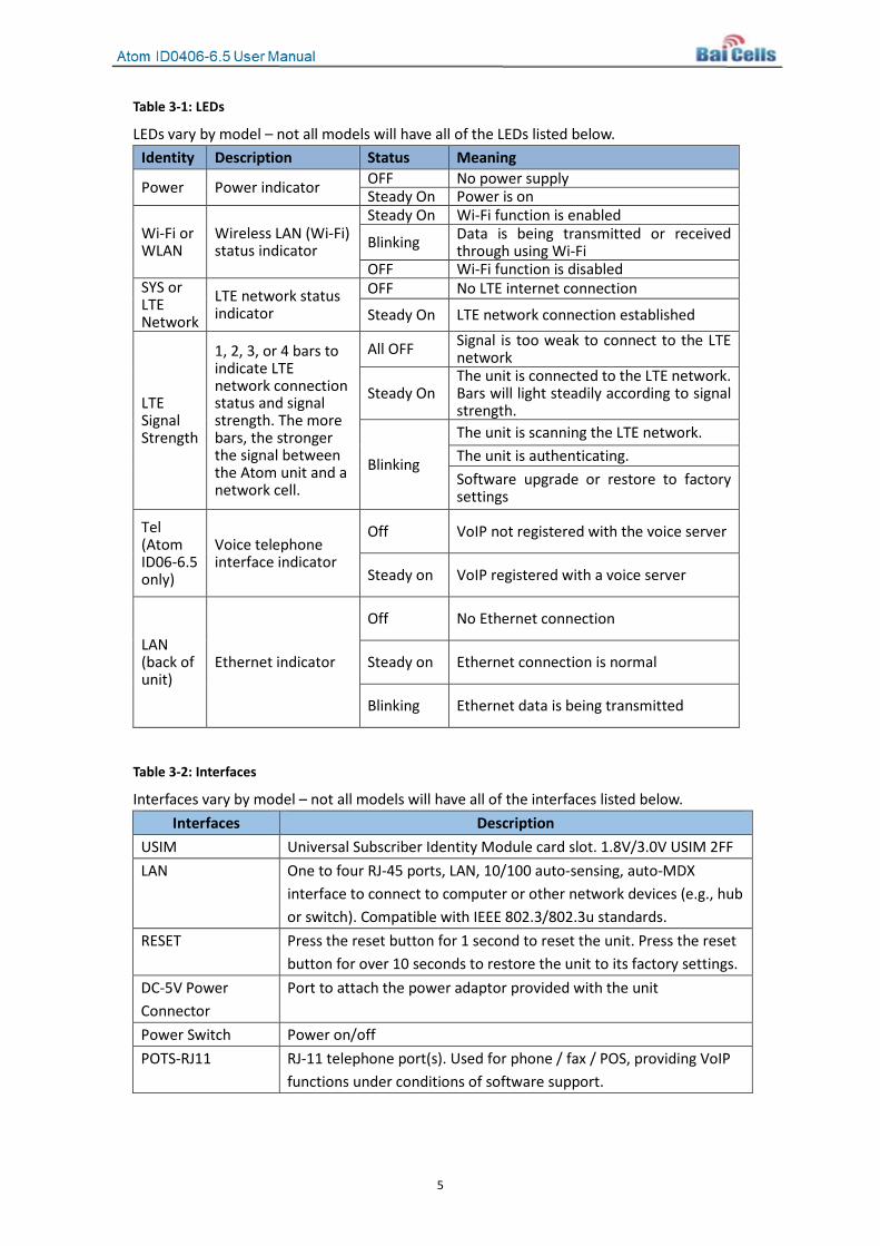
Table 3-1: LEDs
LEDs vary by model – not all models will have all of the LEDs listed below. Identity Description Status Meaning
Power Power indicator OFF No power supply Steady On Power is on
Wi-Fi or WLAN
Wireless LAN (Wi-Fi) status indicator
Steady On Wi-Fi function is enabled
Blinking Data is being transmitted or received through using Wi-Fi
OFF Wi-Fi function is disabled SYS or LTE Network
LTE network status indicator
OFF No LTE internet connection
Steady On LTE network connection established
LTE Signal Strength
1, 2, 3, or 4 bars to indicate LTE network connection status and signal strength. The more bars, the stronger the signal between the Atom unit and a network cell.
All OFF Signal is too weak to connect to the LTE network
Steady On The unit is connected to the LTE network. Bars will light steadily according to signal strength.
Blinking
The unit is scanning the LTE network. The unit is authenticating. Software upgrade or restore to factory settings
Tel (Atom ID06-6.5 only)
Voice telephone interface indicator
Off VoIP not registered with the voice server
Steady on VoIP registered with a voice server
LAN (back of unit)
Ethernet indicator
Off No Ethernet connection
Steady on Ethernet connection is normal
Blinking Ethernet data is being transmitted
Table 3-2: Interfaces
Interfaces vary by model – not all models will have all of the interfaces listed below. Interfaces Description
USIM Universal Subscriber Identity Module card slot. 1.8V/3.0V USIM 2FF LAN One to four RJ-45 ports, LAN, 10/100 auto-sensing, auto-MDX
interface to connect to computer or other network devices (e.g., hub or switch). Compatible with IEEE 802.3/802.3u standards.
RESET Press the reset button for 1 second to reset the unit. Press the reset button for over 10 seconds to restore the unit to its factory settings.
DC-5V Power Connector
Port to attach the power adaptor provided with the unit
Power Switch Power on/off POTS-RJ11 RJ-11 telephone port(s). Used for phone / fax / POS, providing VoIP
functions under conditions of software support.

6
4. Installation Follow the steps below to install the ID04/06-6.5 unit.
ATTENTION: Make sure the unit is turned off before you insert or remove
the USIM card. Otherwise, the unit and USIM card may be damaged.
1. Insert the USIM card: Open the protective cover of the USIM card slot on the top of the Atom unit, and insert the USIM card into the slot (Figure 4-1). Then, close the protective cover.
Figure 4-1: USIM
2. Connect the cables (Figure 4-2):
a. LAN: Connect one end of the RJ-45 Ethernet cable to the LAN interface on the unit, and the other end to the computer.
b. Power: Connect the DC-5V power adaptor to the power connector and electrical outlet.
c. Turn the power switch to ON.
Figure 4-2: Cables
3. Connect to the network:
a. Open a Web browser, and in the address bar type http://192.168.254.1 (or http://192.168.1.1 if on older firmware than V1.0.3) and press Enter.

7
b. Enter the default user name (admin) and password (admin), and select Login. In the upper right corner of the GUI window you should see LTE network signal strength indicators (described in Table 3-1 LEDs). The bars should be in “steady on” state. Refer to Table 4-1.
Table 4-1: LTE Signal Strength
1, 2, 3, or 4 lighted bars indicate LTE network connection status and signal strength. The more bars, the stronger the signal between the Atom unit and a network cell.
If the Atom unit cannot detect a wireless signal, or if the signal is very weak (e.g., only 1 bar), try moving the unit closer to a window, higher up and away from other radiating or blocking objects. Otherwise, contact your service provider for assistance.
4. Connect Wi-Fi:
a. Ensure that the computer or other smart device has Wi-Fi (WLAN) enabled.
b. When the Wi-Fi (or WLAN) LED on the unit shows “steady on”, per Table 3-1 LEDs, it is functional.
NOTE: Wi-Fi/WLAN function can be enabled or disabled through the Web GUI.
c. Looking at the label on the back of the Atom unit, record the WLAN Name and WLAN KEY (WPA/WPA2) values (Figure 4-3).
Figure 4-3: Label
To avoid unauthorized user access to the Wi-Fi/WLAN, using the Web GUI modify the WLAN Name and WLAN Key (WPA/WPA2) information supplied by your service provider. These fields are case-sensitive. On your Wi-Fi enbled computer and other smart devices, you can then look for the new Wi-Fi/WLAN network name.

8
5. Basic Configuration To configure the Atom user equipment (UE), you will access the local or Web-based GUI application. Follow the steps provided to log in and complete the minimal configuration requirements for the UE to operate. For more detailed configuration information covering all of the GUI fields, refer to the Baicells Configuration and Network Administration Guide on the Baicells website.
5.1 Log in and Change the Password Follow the steps below to access and log in to the UE GUI application.
1. Switch on the UE power. 2. Open a Web browser, and enter:
a. http://192.168.150.1 (Gen 2 UEs), b. http://192.168.254.1 (Gen 1 UEs), or c. http://192.168.1.1 (Gen 1 UEs on firmware older than V1.0.3),
and then press Enter. 3. At the login window (Figure 5-1), enter the default user name (admin) and password
(admin), and select Login.
Figure 5-1: Login
4. After you log in, the main menu is shown in the left navigation pane (Figure 5-2). To
protect your UE from unauthorized access, go to System > admin to configure a new password (Figure 5-3). The password may be 5 to 8 ASCII characters (letters, numbers, and special characters). Baicells recommends using a mix of upper and lower case letters plus numbers. Click on SAVE & APPLY.

9
Figure 5-2: Main Menu
Figure 5-3: Change Password
5.2 Configure Network Mode 1. Go to Network > WAN Settings (Figure 5-4). For the Network Mode, choose either
Network Address Translation (NAT) or Bridge mode according to your LTE network setup. NAT allows multiple hosts on a private network to access the internet using a single public IP address. Selecting Bridge mode disables NAT and allows the UE to function as a DHCP server without IP address conflict.
2. Click on SAVE & APPLY to complete the configuration.

10
Figure 5-4: Network Mode
5.3 Configure LTE Connection Method 1. Choose LTE > Connection Method to choose the LTE connection setting for this UE as
either Auto connect or Manual connect (Figure 5-5) to the LTE network. If you choose Automatic, click on SAVE & APPLY to save your selection. If you choose Manual, go to step 2.
Figure 5-5: Connection Method
2. To manually connect the UE to the LTE network, choose Manual connect and click on
PLMN for Public Land Mobile Network to scan all available networks and to select a specific LTE network to connect to. Select Connect to connect to the network. Use the Disconnect button to disconnect from the selected network.
5.4 Configure Scan Method The Scan Method setting determines which frequencies the UE’s routine scan of available frequencies will cover. Scanning is a process of tuning to a specific frequency and measuring the simplest signal quality [e.g., Received Signal Strength Indication (RSSI)]. As part of the cell selection and reselection process, the UE performs the scan first and then selects a small number of candidate cells to go through the next step of measuring and evaluating signals to select the best eNB to serve it.

11
Go to Network > Scan Method, and select either FullBand, PCI Lock, or Band/Frequency Preferred, as shown in Figure 5-6. The options are explained beneath the figure. Click on Submit to save the configuration.
Figure 5-6: Scan Method
• FullBand – The UE will routinely scan all channels in the band, which can make the time it takes to connect longer than the other modes. The band is dependent on the model of UE being used. Click on Submit after selecting this option.
• Frequency Lock – You can specify which band(s) the UE will scan. Select Frequency Lock, and click on Add List. This will open a new window where you can input the band number and the preferred E-UTRA Absolutely Radio Frequency Channel number (EARFCN) (Figure 5-7). Click on Add to add the list. You can add more than one list.
• PCI Lock – Allows you to select the specific E-UTRA Absolute Radio Frequency Channel Number (EARFCN) and Physical Cell Identifier (PCI). Click on Add List to enter the settings (Figure 5-8). After entering the information, click on Add. You can add more than one PCI Lock list. The UE will scan the list for eNBs with the PCI and EARFCN combination.
After entering the configuration settings, click on SAVE & APPLY to save the changes.
Figure 5-7: Frequency Lock

12
Figure 5-8: PCI Lock
5.5 Configure APN Management An Access Point Name (APN) is the name of a gateway between a 3G/4G mobile network and another computer network, frequently the public internet. The UE supports 4 APN configurations. Go to LTE > APN Management to configure the different services (Figure 5-9 and Table 5-1). Click on SAVE & APPLY to activate the data. The bottom of the screen lists any APNs that have been defined for this UE.
Figure 5-9: APN Management

13
Table 5-1: APN Management
Field Name Description
APN Number Select the APN number – 1, 2, 3, or 4
Enable Select the check box next to Enable to enable this APN
APN Name Enter the name of this APN, as defined in the eNB configuration
Default Gateway To enable a default gateway to this eNB, select the check box next to Enable.
Apply To Select either No [None] Specified, TR069, SNMP, or SNMP+TR069 to indicate which protocol may be used to collect information about the eNBs to which this UE may connect.

14
Appendix A: Technical Specifications
Basic Specifications
Item Description
LTE Standard ID04-6.5: 3GPP Release 9, CAT 4 ID06-6.5: 3GPP Release 10, CAT 6/7
Ethernet LAN Port One RJ-45 port: ID04-6.5 is 10/100 and ID06-6.5 10/100/1000 auto-sensing, auto-MDX
LED Indicators Power / SYS or LTE (Tel) / LTE Signal / WLAN POTS Port 1 RJ-11 interface USIM 1.8V/3V 2FF
Restore Button Tactile button. Press for at least 10 seconds to restore the UE to factory settings.
Power Switch On/Off
Power Supply Input: Universal range 100V to 240V AC Output: 12VDC, 1.5A
Battery Customization Dimensions (HxWxD) 7.6 x 6.6 x 2.9 in / 193 x 168 x 74 mm Weight 14 oz (400 g)
RF Specifications
Different models support different frequencies, antennas, and carrier aggregation configurations.
Item Description LTE Mode FDD/TDD Channel Bandwidth 5 / 10 / 15 / 20 MHz
MAX Output Power ID04-6.5: 23 dBm ±2 dBm ID06-6.5: 23 dBm ±2 dBm per transmit antenna
Frequency Bands
• ID04-6.5: o FDD Bands 3/7/38 o TDD Bands 40/41, 42/43/48
• ID06-6.5: o FDD Bands 34/38/39/40/41 o TDD Bands 3/7/20, 3/8/28, 42/43/48
TXRX ID04-6.5: 1T2R ID06-6.5: 1T4R, 2T4R (uplink enhanced)
Carrier Aggregation Atom ID06-6.5 only: 2CC CA Antenna Gain 6.5 dBi @ 3.x GHz

15
5 dBi @ 2.x GHz 4 dBi @ 1.x GHz 3 dBi @ sub-1 GHz
Peak Rate
• ID04-6.5: o FDD - DL 100 Mbps, UL 50 Mbps o TDD - DL 100 Mbps, UL 10 Mbps (2:7)
• ID06-6.5: o FDD DL 300 Mbps, UL 75 Mbps o TDD DL 220 Mbps, UL 15 Mbps (2:7)
Modulation
• ID04-6.5: o UL: QPSK, 16QAM o DL: QPSK, 16QAM, 64QAM
• ID06-6.5: o UL: QPSK, 16QAM, 64QAM o DL: QPSK, 16QAM, 64QAM
Receive Sensitivity -94 dBm @ QPSK, 20 MHz, 25℃ Antenna Type Internal omni Polarization Linear, vertical Antenna Efficiency > 70% Isolation N/A VSWR ≤ 2 Horizontal Beamwidth (3 dB)
N/A
Vertical Beamwidth (3 dB)
N/A
Wi-Fi Specifications
Item Description Standard IEEE 802.11b/g/n Channel Bandwidth 20/40 MHz Frequency 2.4 GHz TXRX 2T2R MIMO 2x2
Peak Rate • 802.11b: 11 Mbps • 802.11g: 54 Mbps • 802.11n: 300 Mbps
Modulation DSSS/CCK, OFDM
Receive Sensitivity • -64 dBm @ 65 Mbps, typical for 802.11n • -65 dBm @ 54 Mbps, typical for 802.11g • -76 dBm @ 11 Mbps, typical for 802.11b
Max Output Power 17 ±3dBm Antenna Type Internal omni

16
Antenna Gain 2 dBi Active Users 32
SW Specifications
Item Description Network Mode NAT / Bridge / Tunnel IP Protocol IPv4 / IPv6
SIM • PIN management • SIM lock
Network Connection Management
Auto / Manual
LTE Scan Mode Full band scan, frequency lock
WLAN • WPS • MSSID Isolation • VLAN
VPN • ID04-6.5: L2TP, GRE, PPTP, L2 VxLAN • ID06-6.5: L2TP L2/L3, GRE L2/L3
NAT Port forwarding, port trigger, DMZ, ALG
Statistics
LTE status/connection time/system up time Device status DHCP client list Wi-Fi station list LTE status Firewall status
Firewall
• IP/MAC/URL filter • Access control • Block port scanner / SYN flood • SPI filter
Network Management • ID04-6.5: TR069, SNMP • ID06-6.5: TR069, TR104, SNMP
Diagnostics • TCP dump • Ping • Trace route
Maintenance
• Date and time setting • Reboot • Restore factory settings • Restore / back up configuration files • Firmware upgrade locally or OTA
System Logs • Operating • Run-time • Filter/select/display/export
Antenna Selection ID06-6.5: Customization

17
Environmental Specifications
Item Description
Operating Temperature 14°F to 113°F, -10℃ to 45℃
Storage Temperature -4°F to 158°F, -20℃ to 70℃ Operating Humidity 5% to 95%
Voice Specifications (Atom ID06-6.5 Only)
Item Description
VoIP
• Dual-APN • SIP ALG • G711 fax pass-through • T38 fax relay
Global Part Numbers
Model Description EG2011B-M3 Atom Indoor 6dBi UE
CAT 6/7, 2T4R, Bands 40/41 EG2013B-M11 Atom Indoor 6dBi UE
CAT 6/7, 2T4R, Bands 42/43/48 EG2030C-M1 Atom Indoor Cat4 UE, 2.5 GHz, 6 dBi, B40/41, Gen 2 EG2030C-M2 Atom Indoor Cat4 UE, 3.5 GHz, 6 dBi, B42.43, Gen 2 EG2230C-M10 Atom Indoor 6dBi UE
CAT 4, 1T2R, Bands 7/38 EG2030C-M11 Atom Indoo 6dBi UE
CAT 4, 1T2R, Bands 42/43/48

18
Appendix B: CloudKey More recent releases of UE firmware (for example, version 1.0.8) allow the operator to pre-configure the UE using the Baicells CloudCore Operations Management Console (OMC). The operator enters their CloudKey account information in the UE Web GUI or through the OMC, as follows. UE GUI: Log in to the UE GUI for the device.
1. Click on the System tab located on the left. 2. Click on TRO69. 3. Enter the operator’s CloudKey information in the box marked CloudKey. (The
operator’s CloudKey information is shown in the top right corner of their CloudCore account. Each CloudKey is unique to each operator.)
4. Click on Submit, and once the UE attaches to the eNB the UE will apear in the OMC Monitor window. A reboot is not required for this field to take effect.
OMC: Alternatively the operator can use the OMC Device Manager function to add the UE.
1. Log in to your OMC account. 2. Click on System > Device Management. 3. Click +Add in the top right corner. 4. A popup window will appear. Enter the UE’s MAC address, and the UE device will be
added to the operator’s account.

19
Appendix C: FAQs If you have questions, please check the list of frequently asked questions (FAQs) on the Baicells support website or the Facebook support forum.
• Baicells support website - https://na.Baicells.com/support/
• Baicells support forum on Facebook - https://www.facebook.com/groups/Baicellsoperatorsupportgroup/