Embed Size (px)
Citation preview

Draft version 1.0
ATLAS NOTEAugust 25, 2012
Electron Identification Studies for the Level 1 Trigger Upgrade1
L. Feremengaa, M.-A. Pleierb, F. Lannib2
aUniversity of Texas at Arlington3bBrookhaven National Laboratory4
Abstract5
This note shows that it is very difficult to reject neutral pions from electrons at6
Level 1 trigger of the ATLAS trigger system. The lateral profiles of electrons and7
neutral pions are different when the interaction point of the colliding protons is at8
z = 0 and a good rejection criteria is achieved. Although this rejection criteria is9
stable against increasing pileup, it fails for a more realistic model of the luminous10
profile of the proton beam. A variable used at Level 2 trigger is also shown in this11
note to be unstable against increasing pileup.12
c© Copyright 2012 CERN for the benefit of the ATLAS Collaboration.Reproduction of this article or parts of it is allowed as specified in the CC-BY-3.0 license.

August 25, 2012 – 13 : 26 DRAFT 1
1 Introduction13
Throughout its successful operation, the LHC has had a nominal energy increase from√
s =14
1.8 TeV in 2009 to√
s = 7 TeV in 2011 [1][2]. The luminosity has also increased from 2.1 ×15
1032cm−2s−1 in 2010 to approximately 7 × 1033cm−2s−1 in 2012 [3][4]. In 2014, we expect the16
LHC to collide protons at√
s = 13 TeV to 14 TeV after the upgrade [5]. In the following years17
the LHC will be perfoming precision measurements, in particular on the recently discovered18
candidate for the Higgs boson. This requires a major upgrade on luminosity because this Higgs19
candidate has a very low production cross section. By 2019 the LHC is expected to reach an20
instantaneous luminosity of approximately 3 × 1034cm−2s−1. This increase in luminosity will21
impact both the selection efficiency and the trigger rates for low pT objects. An upgrade of22
the Level 1 trigger was proposed in which groups of cells called supercells are used instead of23
Trigger Towers [6].24
In this study it is shown that it is not possible to reject neutral pions from electrons using25
∆η×∆φ = 0.025× 0.1 super-cells. The longitudinal profiles of the electrons and the neutral pions26
are found to be too similar to be exploited for neutral pions rejection. A variable that relies27
on the differences between the lateral profiles of neutral pions and electrons to reject neutral28
pions is introduced. This variable is stable against increasing pileup and separates electrons29
from neutral pions in the ideal case when the interaction point is at z = 0, where it makes30
optimal use of the projective geometry of the calorimeter. It fails for a more realistic model31
of the luminous profile of the beam, which is no longer a δ-function at z = 0 but a Gaussian32
distribution with a width of approximately 5 cm. The variable currently used at Level 2 trigger33
that exploits the two maxima of energy deposited by neutral pions is shown to be less effective34
against increasing pileup, prompting more detailed studies in the future.35
2 The ATLAS Trigger36
The ATLAS Trigger system comprises three levels [7][8]. This study is restricted to the first37
level (L1). At this level, regions in the calorimeter are identified that have energy deposits38
larger than a predefined threshold. To maintain high processing speeds it is not possible to do39
this on a cell level and therefore exploit the full granularity of the calorimeter. Coarser regions40
of size ∆η×∆φ = 0.1× 0.1 (Trigger Towers, TT) in the electromagnetic section of the calorimeter41
(EM Cal) are used instead. The EM Cal has four layers and these are the Presampler (PS) and42
the first (Layer 1) up to the third layer (Layer 3). Layer 1 comprises strips which are narrower in43
η than the cells in Layer 2. Layer 2 has the largest radiation length of the EM Cal and therefore44
receives the largest fraction of energy from electromagnetic objects. Cells in the PS and Layer45
2 have the same width in η (∆η = 0.025) and the widest cells in η are in Layer 3 (∆η = 0.05).46
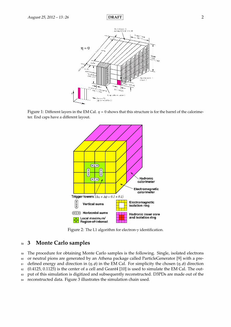
Figure 1 shows the segmentation of the different layers for the barrel of the calorimeter. In this47
study we concentrate only on the barrel.48
In Layer 2 one TT comprises 4 × 4 cells in (η × φ). The current L1 trigger algorithm first49
runs a sliding window to find a local maximum that comprises 2 × 2 TTs in (η, φ). These 2 × 250
tower regions shown in green in Figure 2 are called Clusters. The algorithm then computes the51
horizontal and the vertical sums of energy in this local maximum and labels the highest as the52
candidate energy for the cluster. It accepts the cluster if this energy is greater than the threshold53
energy, otherwise the cluster is rejected. The neighboring towers that sorround the cluster make54
up the Isolation Ring (IR). A ratio of the cluster energy and the IR is a good variable to study55
the lateral profiles of differenct objects, and in particular can be used to separate EM objects56
against hadronic objects at trigger level.57
August 25, 2012 – 13 : 26 DRAFT 2
Figure 1: Different layers in the EM Cal. η = 0 shows that this structure is for the barrel of the calorime-ter. End caps have a different layout.
Figure 2: The L1 algorithm for electron-γ identification.
3 Monte Carlo samples58
The procedure for obtaining Monte Carlo samples is the following. Single, isolated electrons59
or neutral pions are generated by an Athena package called ParticleGenerator [9] with a pre-60
defined energy and direction in (η, φ) in the EM Cal. For simplicity the chosen (η, φ) direction61
(0.4125, 0.1125) is the center of a cell and Geant4 [10] is used to simulate the EM Cal. The out-62
put of this simulation is digitized and subsequently reconstructed. D3PDs are made out of the63
reconstructed data. Figure 3 illustrates the simulation chain used.64

August 25, 2012 – 13 : 26 DRAFT 3
ParticleGeneration
(Single, Isolated,
ParticleGenerator)
EM Cal(Geant4, (η0 , φ0) =
(0.4125, 0.1125),
Center of a cell)
Data Dig-itization
(rdo)
Datarecon-
struction
MakeD3PDs
rdo→ esd
esd→ d3pd
Figure 3: Flowchart of the sample generation chain.
Separate Monte Carlo samples were also made in which electrons and neutral pions were65
generated over a range in η covering the width of a cell in Layer 2 (∆η = 0.025) which is also the66
width of a supercell. We will refer to samples generated in this manner as scanned η samples.67
The samples generated as described in the preceding paragraph are fixed η samples.68
ParticleGenerator by default assumes that the interaction point of the particles in the col-69
lider can be described by a δ−function at z = 0. This is the ideal situation. A more realistic70
model describes the interaction point with a Gaussian distribution with RMS ≈ 5cm. In this71
note, we refer to this effect as Vertex Smearing.72
4 Results73
4.1 Longitudinal Profile74
One variable ρlayer that quantifies the depth profile of an object is the fraction of energy de-75
posited in a layer of the calorimeter and the total energy deposited in all four layers. In this76
study, the total energy is the energy deposited in the cluster with the most energy in the barrel77
of the calorimeter. ρlayer for a particular layer is then the ratio of the energy deposited in the78
layer and cluster in question, and this total energy:79
ρlayer =
∑c∈cl,c∈layer(Ec)
Ecl, (1)
where layer ∈ {0, 1, 2, 3}, cl is the cluster that contains the most energy and c represents80
individual cells whose dimensions depend on the layer. For the PS and for Layer 3 Figure 481
shows that the deposited energy fraction is less than 5% for all studied particle energies. Most82
of the energy is deposited in Layer 1 and Layer 2. This study therefore concentrates on Layer 183
and Layer 2.84
Figure 5 (left) is an overlay of ρ1 and ρ2 for both electrons and pions for increasing electron85
or pion energy. Since we are mostly interested with triggering for low pT objects, we restrict our86
analysis to objects with not more than 50 GeV. It is clear from Figure 5 that electrons and pions87
exhibit similar longitudinal profiles. The plot on the right in the same Figure is a 2-dimensional88
distribution of ρ1 vs. ρ2 for 20 GeV electrons and 20 GeV neutral pions. Both electrons and89
pions show the expected anticorrelation in ρ1 and ρ2; there are no differences strong enough90
to warrant a separation. Figure 6 shows an example distribution for 20 GeV objects in ρ1 (left)91
and for ρ2 (right). No simple cuts can be made on both variables that will reject a significant92
fraction of neutral pions without losing more than 5% of electrons.93

August 25, 2012 – 13 : 26 DRAFT 4
Figure 4: [Left] ρlayer for electrons for all the layers of the EM Cal. [Right] ρlayer for neutral pions for allthe layers of the EM Cal.
Figure 5: [Left] A comparison of neutral pions and electrons in ρ1 and ρ2 versus increasing incidentenergy. [Right] ρ1 versus ρ2 for electrons and neutral pions.
For further comparison between the fraction of energy deposited in Layer 1 and in Layer 2,94
we introduce95
ρcomp =ρ1
ρ2(2)
One advantage that ρcomp has over the other possible variables is that it is less sensitive to96
pileup because pileup offsets in ρ1 and in ρ2 cancel out. That minimizes uncertainties. Figure 797
is an overlay of ρcomp for electrons and neutral pions versus their energy. Again, there are no98
major differences that can enable separation between these two objects for energies less than99
50 GeV.100
Figure 8 shows ρcomp for 20 GeV electrons and pions. Again, no simple cuts can be made101
that will reduce background significantly and yet maintain less than 1% signal loss. Similar102
studies at different and higher pileups show no differences as expected (Figure 8 right). Pileup103
therefore does not affect ρcomp. In the next section we will therefore study the possibility of104
electron-neutral pion separation based on the lateral profiles.105

August 25, 2012 – 13 : 26 DRAFT 5
Figure 6: [Left] ρ1 distribution for 20 GeV electrons and neutral pions. [Right] ρ2 distribution for 20 GeVelectrons and neutral pions.
Figure 7: ρcomp versus the incident energy of electrons and neutral pions.
Figure 8: [Left] ρcomp distribution for 20 GeV electrons and neutral pions. [Right] ρcomp distribution for20 GeV electrons at different pileups.

August 25, 2012 – 13 : 26 DRAFT 6
4.2 Lateral Profile106
The electron-γ identification algorithms used offline and those used for the Level 2 trigger have107
access to full granularity. Offline algorithms are used as a benchmark for any differences be-108
tween the lateral profiles of the electrons and the neutral pions. These differences can therefore109
offer some insight onto rejection techniques for triggering. In Layer 1, one variable that quan-110
tifies this is the number of strips that have both energy hits above a certain threshold and the111
same φ position as the strip with the most energy. Figure 9 (left) shows this variable versus the112
energy of electrons and neutral pions. The threshold energy here is 1% of the energy contained113
in the cluster with the most energy. For low energy objects, and hence for low pT objects, a114
separation between electrons and neutral pions can be easily deduced since for objects with115
energy less than 30 GeV the profile for neutral pions is on average one strip wider. Figure 9116
(right) shows an example distribution for 20 GeV objects. Since in Layer 1 the supercells are 8117
strips wide (Figure 1), we can deduce from Figure 9 (right) that the energy shower in Layer 1118
is contained in at most two neighboring supercells for the no-pileup case (µ = 0). For 20 GeV119
electrons Figure 10 shows that at higher pileup the electron profile does not change 1. This120
implies that neutral pions at higher pileup also have a wider energy shower.121
Figure 9: [left] Mean number of strips with hits > 1% of cluster energy vs. e−/π0 energy. [right] Meannumber of strips with hits > 1% of cluster energy at 20GeV for electrons and neutral pions
4.2.1 R(1)η122
For online neutral pion rejection we introduce123
R(1)η =
E0
E1 + E0 + E−1(3)
where E0 is the energy deposited in the supercell with the most energy and E±l is the en-124
ergy deposited in ±l supercells around the supercell in η with the most energy. We use three125
supercells here since the energy shower is contained in at most two supercells (Figure 9 (right)).126
The left plot in Figure 11 shows how R(1)η for electrons differs from that of neutral pions for in-127
creasing energies and the one on the right in the same Figure shows the distribution for 20 GeV128
electrons and neutral pions as an example. Distributions shown in Figure 11 are from Monte129
1The Monte-Carlo samples used for electrons in Figure 9 (right) are not the same as those used for µ = 0 inFigure 10. This explains why the distributions are not identical.

August 25, 2012 – 13 : 26 DRAFT 7
Figure 10: Number of strips with hits > 1% of cluster energy at different pileups, for 20 GeV electrons
Carlo samples with vertex smearing turned off and fixed η. For low pT objects, a good sepa-130
ration can be achieved between electrons and neutral pions. For 20 GeV objects when vertex131
smearing is turned off, a rejection criteria based on R(1)η can reject more than 50% of neutral132
pions while losing less than 5% of the total electrons.133
Figure 11: [Left] R(1)η versus the incident energy of electrons and neutral pions when vertex smearing is
turned off and fixed η. [Right] R(1)η for 20 GeV electrons and neutral pions when vertex smearing is off
and η is fixed.
Figure 12 shows how the distribution for R(1)η changes for 20 GeV electrons and neutral pions134
when vertex smearing is turned on. When vertex smearing is turned on, projection onto a single135
supercell deteriorates for a fraction of events. This is evident from a tail that develops for the136
electron R(1)η distribution. The change in the tail is not apparent for neutral pions because their137
distribution is spread out even without vertex smearing. The result of this is a loss of separation138
between electrons and neutral pions when vertex smearing is turned on. Since the the model139
with vertex smearing is more realistic, we restrict our analysis to that.140
Figure 13 shows R(1)η when electrons or neutral pions are scanned over a ∆η = 0.025 range,141
which is the width of a supercell in η. As expected, scanning over η does not restore the separa-142
tion between electrons and neutral pions. There are also no major differences between scanning143
and fixing η, so restrict our studies to the case when η is fixed.144
The algorithm that calculates R(1)η first identifies the supercell with the highest energy in145
Layer 2 and then uses the same (η, φ) position to identify the supercell with the highest energy146

August 25, 2012 – 13 : 26 DRAFT 8
Figure 12: R(1)η for 20 GeV electrons and neutral pions when vertex smearing is on and η is fixed.
Figure 13: R(1)η for 20 GeV electrons and neutral pions when vertex smearing is on and η is scanned.
in Layer 1. This approach correctly identifies the supercell with the highest energy in Layer 1147
when vertex smearing is turned off, but when the vertex smearing is turned on it is possible148
to wrongly identify this supercell. Rather than using collider coordinates (η, φ) to identify cells149
and supercells, we label each cell and supercell with two individual indices (iη, iφ). The variable150
∆η = iηH1 − iηH2, (4)
quantifies how aligned the supercells are in Layer 1 and Layer 2, where iηH j2 is the η index151
for the supercell in layer j with the highest energy. The left plot in Figure 14 shows how ∆η152
changes when vertex smearing is on. When vertex smearing is off, using the supercell in layer153
2 as the seed correctly identifies the highest-energy supercell in layer 1. When vertex smearing154
is turned on, this algorithm fails for a fraction of events so it becomes important to seed from155
Layer 1. The right plot in Figure 14 shows R(1)η when the highest-energy supercell is seeded156
from Layer 1, and when vertex smearing is turned on. Since almost all the energy is deposited157
in two neighboring supercells, the highest-energy one included, when the correct supercell is158
identified R(1)η is always greater than or equal to 0.5. The fraction of events that a supercell is159
incorrectly identified when seeding from Layer 2 is so small that correcting the seed does not160
yield a visible improvement in separation between electrons and neutral pions.161
2This index is weighted with energy. iηH j =∑
k Ek×iηk∑k Ek
where k ∈ {0,±1} identifies the supercells, 0 being thehighest-energy supercells and ±1 is for the neighboring supercells.

August 25, 2012 – 13 : 26 DRAFT 9
Figure 14: [Left] ∆η for electrons when vertex smearing is turned on and off. [Right] R(1)η when seeding
the highest-energy supercell from Layer 1 instead of Layer 2. Vertex smearing is also turned on.
4.2.2 Er for Level 2162
Although the energy deposit from neutral pions is often found to have two maxima because163
of the π0 → γγ decay, these two maxima are normally within one supercell in η. It is therefore164
not possible to exploit this property to separate them from electrons at Level 1 trigger using165
supercells. At Level 2 the variable166
Er =Emax − Esmax
Emax + Esmax(5)
is used, where Emax is the energy deposited in the strip that receives the most energy and167
Esmax is the energy deposited in the strip that receives the second largest energy deposit. Since168
electrons normally have one maximum of energy deposition, Er is expected to be close to 1;169
for neutral pions the distribution is expected to be more spread out. Figure 15 shows a good170
separation achieved at level 2 trigger using this variable. The plot on the right in Figure 15171
shows that Er is stable after turning vertex smearing on. This shows that at full granularity, it172
is possible to separate electrons from neutral pions at Level 2 trigger. Figure 16 shows that Er173
is also stable after introducing scanning. As pointed out before, there are no major differences174
between scanning over η and not scanning over η.175
Figure 17 shows the electron efficiency when Er is used at Level 2 trigger and when R(1)η176
is used at Level 1. Er is stable against vertex smearing. At Level 2 Er can reject 60% neutral177
pions while losing not more than 2% electrons (top left). When vertex smearing is turned on,178
60% neutral pions can also be rejected while losing not more than 2% even when η is scanned179
(bottom left). R(1)η deteriorates when vertex smearing is turned on (top right). The deterioration180
of R(1)η is consistent also when η is scanned (bottom right).181
Figure 18 shows the electron efficiency when Er is used at different pileups. It is clear that182
rejection of neutral pions from electrons is significantly reduced at higher pileups when using183
Er. This warrants further investigation in future studies.184
5 Summary and Conclusions185
In order to keep exploring new physics at the LHC using the ATLAS detector we need to up-186
grade its trigger system so that it can accomodate low pT objects that come from rare events. In-187
creasing the granularity of trigger from Trigger Towers to supercells is one of the ways that the188

August 25, 2012 – 13 : 26 DRAFT 10
Figure 15: [Left] Er when vertex smearing is turned off. [Right] Er when vertex smearing is turned on.
Figure 16: Er is not affected by scanning. Good separation between electrons and neutral pions isachieved both when η is fixed and when it is scanned over a range.
Level 1 trigger can be improved. Using supercells in Layer 1 of the electromagnetic calorimeter189
however does not achieve a separation of electrons from neutral pions. In the ideal case when190
the interaction point of the colliding protons is at z = 0 R(1)η can achieve a good separation be-191
tween electrons and neutral pions. In a more realistic case when the luminous profile of the192
colliding beams is more spread out this separation is greatly reduced. Although the variable193
Er, used at Level 2 trigger to reject neutral pions from electrons is stable against spreading out194
the luminous profile of the beam, it becomes inefficient as pileup increases and will likely be195
unusable in Phase-I upgrade conditions (µ = 80) and beyond. Futher studies therefore have to196
be done to improve not only the Level 1 trigger of ATLAS but also the Level 2 trigger.197

August 25, 2012 – 13 : 26 DRAFT 11
Figure 17: [Top Left] Electron efficiency versus the fractions of neutral pions surviving using Er withand without vertex smearing. [Top Right] Electron efficiency versus the fraction of neutral pions surviv-ing using R(1)
η with and without vertex smearing. [Bottom Left] Electron efficiency versus the fractionsof neutral pions surviving using Er with fixed and scanned η, when vertex smearing is turned on. [Bot-tom Right] Electron efficiency versus the fractions of neutral pions surviving using R(1)
η with fixed andscanned η, when vertex smearing is turned on.
Figure 18: Er becomes ineffective at high pileups.
6 Acknowledgements198
We would like to thank Hong Ma for the hours he spent helping us work in the Athena frame-199
work. Also, we are thankful to Jaehoon Yu for the consistent conversations that gave some200

August 25, 2012 – 13 : 26 DRAFT 12
insight onto the direction that this study took.201
References202
[1] ALICE Collaboration, K. Aamodt et al., First proton-proton collisions at the LHC as observed203
with the ALICE detector: Measurement of the charged particle pseudorapidity density at s**(1/2)204
= 900-GeV, Eur.Phys.J. C65 (2010) 111–125, arXiv:0911.5430 [hep-ex].205
[2] ATLAS Collaboration, Further search for supersymmetry at sqrt(s) = 7 TeV in final states with206
jets, missing transverse momentum and isolated leptons with the ATLAS detector,207
arXiv:1208.4688 [hep-ex].208
[3] ATLAS Collaboration, Peak stable luminosity recorded at the end of 2010, 2010.209
https://atlas.web.cern.ch/Atlas/GROUPS/DATAPREPARATION/210
DataSummary/2010/daily-summary.html.211
[4] ATLAS Collaboration, Peak stable luminosity recorded at the end of 2012, 2012. https://212
atlas.web.cern.ch/Atlas/GROUPS/DATAPREPARATION/DataSummary/2012/.213
[5] Letter of Intent for the Phase-I Upgrade of the ATLAS Experiment, Tech. Rep.214
CERN-LHCC-2011-012. LHCC-I-020, CERN, Geneva, Nov, 2011.215
[6] D. O. Damazio and F. Lanni, Higher electromagnetic calorimeter segmentation to improve216
trigger selectivity in high luminosity scenarios, Tech. Rep. ATL-LARG-INT-2012-002, CERN,217
Geneva, Mar, 2012.218
[7] ATLAS detector and physics performance: Technical Design Report, 1. Technical Design Report219
ATLAS. CERN, Geneva, 1999. Electronic version not available.220
[8] ATLAS detector and physics performance: Technical Design Report, 2. Technical Design Report221
ATLAS. CERN, Geneva, 1999. Electronic version not available.222
[9] ATLAS Collaboration, W. Seligman, ParticleGenerator, A Simple Monte-Carlo Generator for223
Athena, 2005.224
http://atlas-sw.cern.ch/cgi-bin/viewcvs-atlas.cgi/offline/225
Generators/ParticleGenerator/doc/ParticleGenerator.pdf?view=co.226
[10] Geant4 Collaboration, Geant4, 2012. http://geant4.cern.ch/.227


![ATLAS NOTE - CERN Document Server · ATLAS NOTE ATLAS-CONF-2016-032 June 16, 2016 ... (2UED/RPP) [34] is also considered. In this model, the compactification of the extra dimensions](https://img.pdfslide.us/doc/110x75/5d4455eb88c9932a398d988e/atlas-note-cern-document-server-atlas-note-atlas-conf-2016-032-june-16-2016.jpg)