Embed Size (px)
Citation preview
ATLAS II User’s Manual
2
ISSUED BY SANDIA NATIONAL LABORATORIES, OPERATED FOR
THE UNITED STATES Department of Energy by Sandia Corporation.
NOTICE: This report was prepared as an account of work sponsored by an agency of the
United States Government. Neither the United States Government, nor any agency thereof,
nor any of their employees, nor any of their contractors, subcontractors, or their employees,
make any warranty, express or implied, or assume any legal liability or responsibility for the
accuracy, completeness, or usefulness of any information, apparatus, product, or process
disclosed, or represent that its use would not infringe privately owned rights. Reference
herein to any specific commercial product, process, or service by trade name, trademark,
manufacturer, or otherwise, does not necessarily constitute or imply its endorsement,
recommendation, or favoring by the United States Government, any agency thereof, or any
of their contractors or subcontractors. The views and opinions expressed herein do not
necessarily state or reflect those of the United States Government, any agency thereof, or
any of their contractors.
Printed in the United States of America. This report has been reproduced directly from the
best available copy.
Available to DOE and DOE contractors from
U.S. Department of Energy
Office of Scientific and Technical Information
P.O. Box 62
Oak Ridge, TN 37831
Telephone: (865)576-8401
Facsimile: (865)576-5728
E-Mail: [email protected]
Online ordering: http://www.DOE.gov/bridge
Available to the public from
U.S. Department of Commerce
National Technical Information Service
5285 Port Royal Rd
Springfield, VA 22161
Telephone: (800)553-6847
Facsimile: (703)605-6900
E-Mail: [email protected]
Online ordering: http://www.ntis.gov/ordering.htm
SAND2004-0481
Unlimited Release
3
SAND2004-0481 Unlimited Release
Printed February 2004
Accurate GPS Time-Linked Data Acquisition System (ATLAS II) Users Manual
Jose Zayas and Perry Jones Wind Energy Technology
Sandia National Laboratories P.O. Box 5800
Albuquerque, NM 87185-0708
Juan Ortiz-Moyet PrimeCore Systems Inc.
8421 Osuna Rd NE. Suite C-1 Albuquerque, NM 87111
Abstract
The Accurate Time-Linked data Acquisition System (ATLAS II) is a small, lightweight, time-synchronized, robust data acquisition system that is capable of acquiring simultane-ous long-term time-series data from both a wind turbine rotor and ground-based instru-mentation. This document is a users manual for the ATLAS II hardware and software. It describes the hardware and software components of ATLAS II, and explains how to install and execute the software.

ATLAS II Users Manual
4
Frontispiece
Micon 65 Turbines in Bushland, Texas, Equipped with the Accurate GPS Time-Linked data Acquisition System (ATLAS II)
ATLAS II Users Manual
5
Acronyms
1PPS One Pulse-per-Second ADAS Advanced Data Acquisition System AGND Analog Ground ATLAS II Accurate GPS Time-Linked data Acquisition System DAM Data Acquisition Module DAQ Data Acquisition DAS Data Acquisition Subsystem DCLK Digital Clock DCS Data Communication Subsystem DGND Digital Ground DMM Digital Multimeter ESD Electrostatic Discharge EU Engineering Units GBCU Ground-Based Computer Unit GBU Ground-Based Unit GND Ground GPS Global Positioning Satellite NREL National Renewable Energy Laboratory ODBC Open Database Connectivity PATSyM Programmable Accurate Time Synchronization Module PCM Pulse Code Modulated PLD Programmable Logic Device PPS Pulse-per-Second PROM Programmable Read-Only Memory RAM Random Access Memory RBU Rotor-Based Unit RX_CLK Receive Clock RX_DATA Receive Data SDAS Smart Data Acquisition System SNL Sandia National Laboratories TSLD Time Since Last Dropout TSS Timing Synchronization Subsystem TTL Transistor/Transistor Logic UPS Uninterruptible Power Supply UTC Universal Time Clock

ATLAS II Users Manual
6
This page intentionally left blank.
ATLAS II Users Manual
7
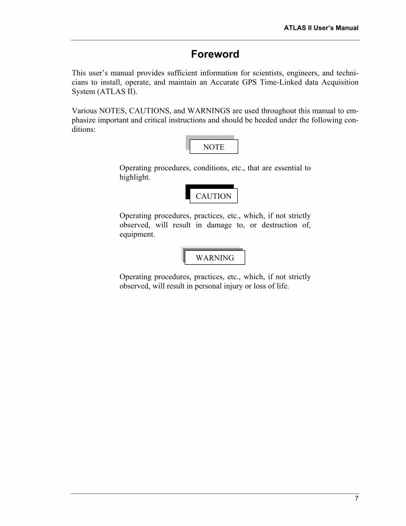
Foreword This users manual provides sufficient information for scientists, engineers, and techni-cians to install, operate, and maintain an Accurate GPS Time-Linked data Acquisition System (ATLAS II).
Various NOTES, CAUTIONS, and WARNINGS are used throughout this manual to em-phasize important and critical instructions and should be heeded under the following con-ditions:
Operating procedures, conditions, etc., that are essential to highlight.
Operating procedures, practices, etc., which, if not strictly observed, will result in damage to, or destruction of, equipment.
Operating procedures, practices, etc., which, if not strictly observed, will result in personal injury or loss of life.
NOTE
CAUTION
WARNING

ATLAS II Users Manual
8
This page intentionally left blank.
Chapter 1. ATLAS II Getting Started ATLAS II Users Manual
9
CHAPTER 1. GETTING STARTED ................................................................................11 1.1 Overview of the ATLAS II Hardware .............................................................11 1.2 Overview of the ATLAS II Software...............................................................14
1.2.1 Installing and Configuring the ATLAS II Software...........................14 1.2.2 Set Up the System Computer .............................................................15 1.2.3 Install the ATLAS II Software ...........................................................16
CHAPTER 2. ATLAS II HARDWARE DESCRIPTION.................................................21 2.1 Data Acquisition Subsystem............................................................................21
2.1.1 DAS Chassis.......................................................................................25 2.1.2 Encoder Module .................................................................................25 2.1.3 Instrumentation Modules....................................................................26 2.1.4 Merger/Decoder Module ....................................................................31
2.2 Data Communication Subsystem.....................................................................32 2.3 Programmable Accurate Time Synchronization Module ................................32 2.4 Lightning Protection Equipment......................................................................38 2.5 Power Supplies ................................................................................................40 2.6 Connectors .......................................................................................................41 2.7 ATLAS II Application-Specific Configuration ...............................................41
2.7.1 Application Planning..........................................................................41 2.7.2 General Fabrication Notes..................................................................46 2.7.3 Ground-Based Unit Assembly............................................................47 2.7.4 Rotor-Based Unit Assembly...............................................................47
CHAPTER 3. ATLAS II SOFTWARE DESCRIPTION ..................................................49 3.1 Capabilities of the ATLAS II software............................................................49 3.2 Introduction to the ATLAS II software ...........................................................49 3.3 Configuring the ATLAS II software................................................................53
3.3.1 Creating a hardware setup ..................................................................58 3.3.2 Configuring ATLAS II DAMs ...........................................................62
3.3.2.1 KAM/ENC/003 - Encoder module parameters ............................................62 3.3.2.2 KAM/ENC/007 - RS-232 Encoder module parameters ...............................64 3.3.2.3 KAM/DEC/002 - Merger/Decoder module parameters ...............................65 3.3.2.4 KAM/ADC/005 - Analog input module parameters ....................................67 3.3.2.5 KAM/ADC/009/S2 - Bridge analog input module parameters ....................69 3.3.2.6 KAM/DSI/002 - Discrete input module parameters.....................................71 3.3.2.7 GPS/001 - GPS receiver/timing reference module parameters ....................74
3.3.3 Configuring Frame Parameters ..........................................................76 3.4 Programming the ATLAS II hardware ............................................................80
3.4.1 Programming a Chassis ......................................................................80 3.4.2 Programming the active DAM ...........................................................83
3.5 Other Software Configuration functions..........................................................85 3.5.1 Managing Setup files..........................................................................85
3.5.1.1 Creating a new setup ....................................................................................85 3.5.1.2 Opening an existing setup ............................................................................87 3.5.1.3 Saving a setup ..............................................................................................87 3.5.1.4 Using an existing setup as a template...........................................................88
3.5.2 Managing a Chassis............................................................................89 3.5.2.1 Modifying a Chassis properties ..................................................................89
Chapter 1. ATLAS II Getting Started ATLAS II Users Manual
10
3.5.2.2 Adding a Chassis to a setup..........................................................................90 3.5.2.3 Removing a Chassis from a setup ................................................................91
3.5.3 Finding a signals definition...............................................................92 3.6 Acquiring Data.................................................................................................94
3.6.1 Starting a DAQ session ......................................................................94 3.6.2 Stopping a DAQ session.....................................................................96 3.6.3 Reading the DAQ Satus information..................................................97
3.7 Displaying Data .............................................................................................101 3.7.1 Displaying Graphical Data ...............................................................103
3.7.1.1 Display/Monitor a signal ............................................................................103 3.7.1.2 Creating a Display setup.............................................................................105 3.7.1.3 Loading a Display setup .............................................................................106 3.7.1.4 Displaying Processed (EU) data.................................................................107 3.7.1.5 Customizing the Graphing window............................................................108 3.7.1.6 Optimizing the Displays performance.......................................................108
3.7.2 Displaying Digital Data....................................................................109 3.8 Controlling the System Update Rate .............................................................111 3.9 Processing Data..............................................................................................112
3.9.1 Configuring Data Processing............................................................112 3.9.1.1 Creating a processing setup........................................................................114 3.9.1.2 Opening an existing processing setup ........................................................117 3.9.1.3 Saving a processing setup...........................................................................118 3.9.1.4 Using an existing processing setup as a template.......................................118
3.9.2 Enabling/Disabling Data Processing................................................119 3.10 Reviewing the Active System Configuration ..............................................121 3.11 Recording (Archiving) Data ........................................................................124
3.11.1 Starting a Data Recording session..................................................124 3.11.2 Stopping a Data Recording session ................................................127 3.11.3 Reading the Data Recording Status information............................127
3.12 Using System Events (Automating ATLAS II) ...........................................129 3.12.1 Introduction to System Events .......................................................129 3.12.2 Creating a new events setup ...........................................................133
3.12.2.1 Defining a system event ...........................................................................134 3.12.2.2 Defining a response to an event ...............................................................135
3.12.3 Editing an event setup ....................................................................144 3.12.3.1 Editing a system event..............................................................................144 3.12.3.2 Editing a response to an event..................................................................144
3.12.4 Managing System Events Setup files .............................................145 3.12.4.1 Opening an existing system events setup .................................................146 3.12.4.2 Saving a system events setup ...................................................................146 3.12.4.3 Using an existing system events setup as a template................................146
3.13 Other Software Utilities ...............................................................................148 3.13.1 PATSyM Diagnostics Utility .........................................................148
CHAPTER 4. REFERENCES .........................................................................................151 CHAPTER 5. TECHNICAL SUPPORT .........................................................................153
Chapter 1. ATLAS II Getting Started ATLAS II Users Manual
11
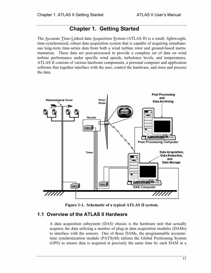
Chapter 1. Getting Started The Accurate Time-Linked data Acquisition System (ATLAS II) is a small, lightweight, time-synchronized, robust data acquisition system that is capable of acquiring simultane-ous long-term time-series data from both a wind turbine rotor and ground-based instru-mentation. These data are post-processed to provide a complete set of data on wind turbine performance under specific wind speeds, turbulence levels, and temperatures. ATLAS II consists of various hardware components, a personal computer and application software that together interface with the user, control the hardware, and store and process the data.
Figure 1-1. Schematic of a typical ATLAS II system.
1.1 Overview of the ATLAS II Hardware
A data acquisition subsystem (DAS) chassis is the hardware unit that actually acquires the data utilizing a number of plug-in data acquisition modules (DAMs) to interface with the sensors. One of those DAMs, the programmable accurate-time synchronization module (PATSyM) utilizes the Global Positioning System (GPS) to ensure data is acquired at precisely the same time by each DAM in a
Chapter 1. ATLAS II Getting Started ATLAS II Users Manual
12
chassis. Moreover, an optional data communications subsystem (DCS) can be used to provide communications between multiple chassis and between a chassis and the system computer. The combination of a chassis (populated with appropriate DAMs and a PATSyM), a DCS, and a power supply unit constitute a Data Acquisition Subsystem (DAS). A DAS is the basic data acquisition unit in an ATLAS II system.
The main strengths of the ATLAS II system are its modularity and flexibility. This is evident in practice where these components are usually packaged into three different types of DAS units: a rotor-based unit (RBU) and two different ground-based units (GBU). The user assembles a complete test system by con-necting any number of DAS units in a master/slave(s) configuration. For the ATLAS II system, the master is defined as the DAS unit that merges the incoming streams from other units and sends the combined data stream to the computer. This way, the user can develop an initial system and easily add more (or remove) DAS units to the system later on as the test requirements change.
A typical test system consists of one RBU, three GBUs, and a system computer (see Figure 1-1). One of the GBUs is designated the master DAS, while all the other DAS units (GBUs and the RBU) are slaves and operate under the control of the master unit. The master unit accepts data streams from the RBU and the slave GBUs, merges these data streams with the data it acquires, and sends the resultant data stream to the system computer. Data transfers between the slaves and the master and between the master and the system computer are normally accom-plished with the use of DCS components.
DCS components work in pairs. If the master unit uses a DCS to transfer data to the system computer, the system computer must contain a DCS to receive that data from the master. If the RBU uses a DCS, the system computer must contain an additional RS-232 radio-modem (not a complete DCS) to communicate with the RBU.
Next, we describe each of the components of an ATLAS II test system in detail:
A rotor-based unit (RBU) typically consists of:
• One Chassis. • One DCS (optional).
Typically consisting of two wireless modems, one for hardware program-ming and the other for transmitting data to either a master unit or to the system computer.
• One PATSyM. Including one GPS antenna and receiver.
• One or more DAMs. • One power supply.
Chapter 1. ATLAS II Getting Started ATLAS II Users Manual
13
• One power conditioning unit. Typically consisting of an 8V voltage regulator, a 5V voltage regulator, and a ter-minal strip.
• Lightning protection equipment (optional).
Additional information on RBU components and assembly may be found in Section 2.7.4.
A ground-based unit (GBU) typically consists of:
• One Chassis. • One DCS (optional).
Typically consisting of one fiber-optics modem for communications to the master unit or to the system computer.
• One PATSyM. Including one GPS antenna and receiver.
• One or more DAMs. • One power supply unit.
This is a separate box including a 24V DC UPS and its battery pack. • One power conditioning unit.
Typically consisting of a 24V to 8V DC-DC converter, a 5V voltage regulator, and a terminal strip.
• Lightning protection equipment (optional).
Additional information on GBU components and assembly may be found in Section 2.7.3 of this manual.
The system computer consists of:
• One IBM PC-compatible computer Refer to Table 1-2 in Section 1.2.2 for the minimum hardware requirements.
• One DCS (optional) Typically consisting of two modems, one for bi-directional RS-232 communica-
tions and the other for receiving data from the master unit. • One or two PCMCIA decoder cards (Pocket Decoder). • ATLAS II software.
More detailed descriptions of the ATLAS II hardware components are provided in Chapter 2.
Chapter 1. ATLAS II Getting Started ATLAS II Users Manual
14
1.2 Overview of the ATLAS II Software
The ATLAS II software is a user-friendly software package that gives the user complete control over the ATLAS II hardware. The main functionality of the ATLAS II Software includes the following features:
1. Data acquisition from a virtually unlimited number of high-level analog, discrete (digital) input, and strain-gauge channels,
2. Simultaneous data acquisition from all channels,
3. Long-term, continuous data acquisition at throughput rates that are only limited by the available processing power of the system computer,
4. Single-event or continuous recording of all acquired data channels,
5. Hardware programming and control via personal computer,
6. Programmable filtering and gain on each analog and strain-gauge channel,
7. Bridge completion circuitry and programmable bridge excitation levels for all strain-gauge channels.
More detailed descriptions of the ATLAS II software components are provided in Chapter 3.
1.2.1 Installing and Configuring the ATLAS II Software
The ATLAS II software installation and configuration procedure consists of the following operations:
1. Installing the ATLAS II software.
2. Executing and configuring the ATLAS II software for the first time. 3. Checking the communication between the computer and each DAS.
The ATLAS II components that are required for a typical installation are listed in Table 1-1.
Chapter 1. ATLAS II Getting Started ATLAS II Users Manual
15
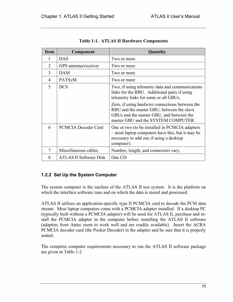
Table 1-1. ATLAS II Hardware Components
Item Component Quantity 1 DAS Two or more 2 GPS antenna/receiver Two or more 3 DAM Two or more 4 PATSyM Two or more 5 DCS Two, if using telemetry data and communications
links for the RBU. Additional pairs if using telemetry links for some or all GBUs. Zero, if using hardwire connections between the RBU and the master GBU, between the slave GBUs and the master GBU, and between the master GBU and the SYSTEM COMPUTER.
6 PCMCIA Decoder Card One or two (to be installed in PCMCIA adapters most laptop computers have this, but it may be necessary to add one if using a desktop computer).
7 Miscellaneous cables Number, length, and connectors vary. 8 ATLAS II Software Disk One CD
1.2.2 Set Up the System Computer
The system computer is the nucleus of the ATLAS II test system. It is the platform on which the interface software runs and on which the data is stored and processed.
ATLAS II utilizes an application-specific type II PCMCIA card to decode the PCM data stream. Most laptop computers come with a PCMCIA adapter installed. If a desktop PC (typically built without a PCMCIA adapter) will be used for ATLAS II, purchase and in-stall the PCMCIA adapter in the computer before installing the ATLAS II software (adapters from Antec seem to work well and are readily available). Insert the ACRA PCMCIA decoder card (the Pocket Decoder) in the adapter and be sure that it is properly seated.
The complete computer requirements necessary to run the ATLAS II software package are given in Table 1-2.
Chapter 1. ATLAS II Getting Started ATLAS II Users Manual
16
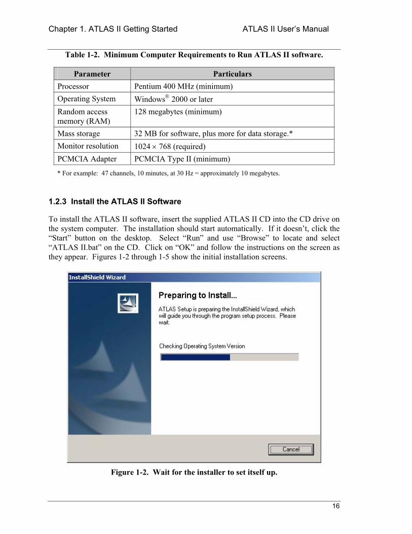
Table 1-2. Minimum Computer Requirements to Run ATLAS II software.
Parameter Particulars Processor Pentium 400 MHz (minimum) Operating System Windows 2000 or later Random access memory (RAM)
128 megabytes (minimum)
Mass storage 32 MB for software, plus more for data storage.* Monitor resolution 1024 × 768 (required) PCMCIA Adapter PCMCIA Type II (minimum)
* For example: 47 channels, 10 minutes, at 30 Hz = approximately 10 megabytes.
1.2.3 Install the ATLAS II Software
To install the ATLAS II software, insert the supplied ATLAS II CD into the CD drive on the system computer. The installation should start automatically. If it doesnt, click the Start button on the desktop. Select Run and use Browse to locate and select ATLAS II.bat on the CD. Click on OK and follow the instructions on the screen as they appear. Figures 1-2 through 1-5 show the initial installation screens.
Figure 1-2. Wait for the installer to set itself up.
Chapter 1. ATLAS II Getting Started ATLAS II Users Manual
17
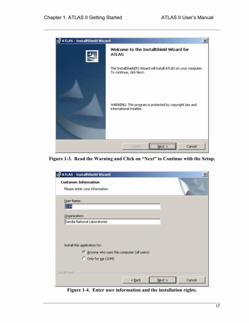
Figure 1-3. Read the Warning and Click on Next to Continue with the Setup.
Figure 1-4. Enter user information and the installation rights.
Chapter 1. ATLAS II Getting Started ATLAS II Users Manual
18
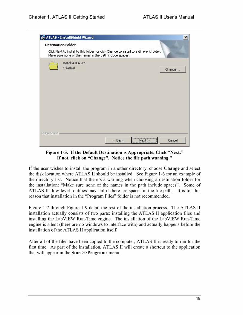
Figure 1-5. If the Default Destination is Appropriate, Click Next. If not, click on Change. Notice the file path warning.
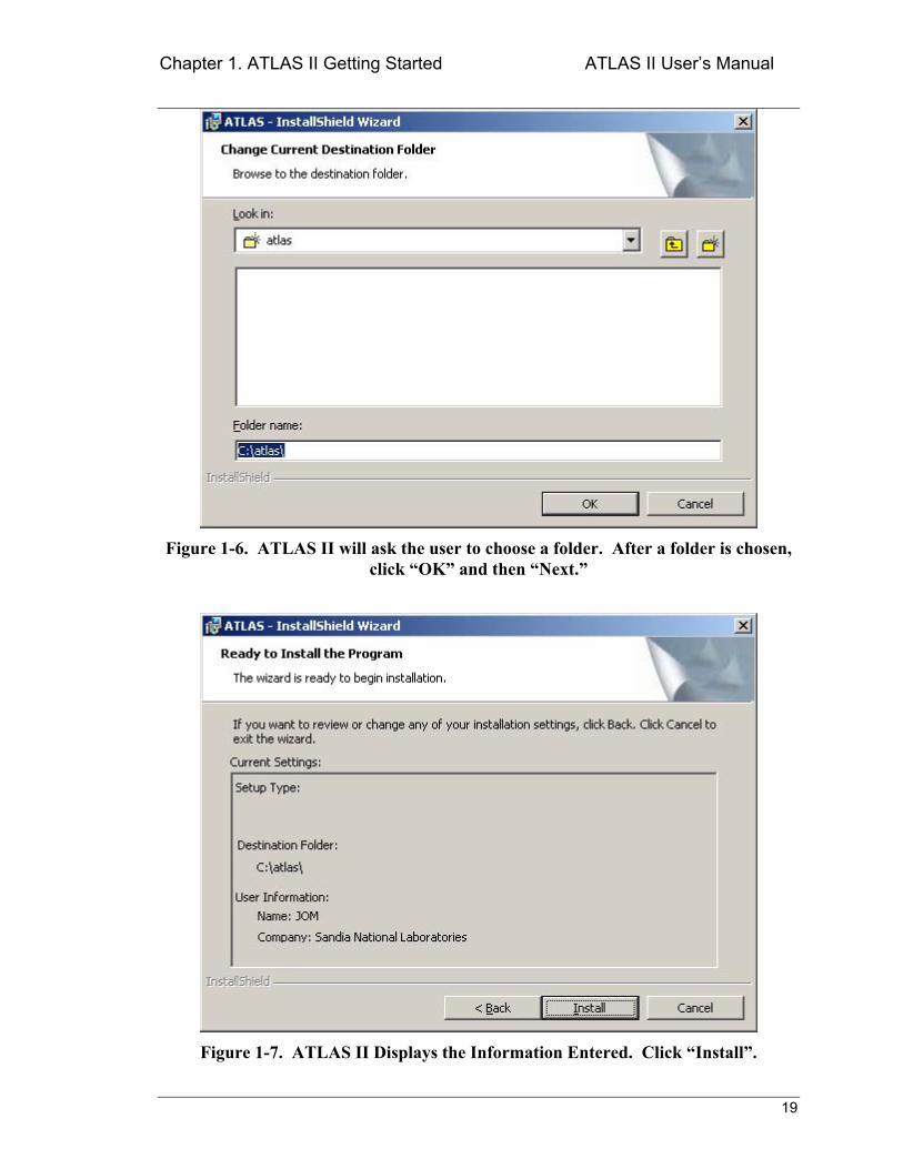
If the user wishes to install the program in another directory, choose Change and select the disk location where ATLAS II should be installed. See Figure 1-6 for an example of the directory list. Notice that theres a warning when choosing a destination folder for the installation: Make sure none of the names in the path include spaces. Some of ATLAS II low-level routines may fail if there are spaces in the file path. It is for this reason that installation in the Program Files folder is not recommended.
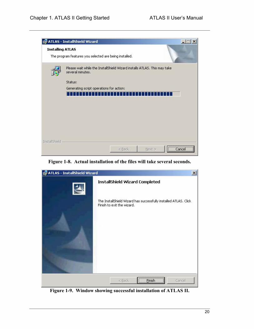
Figure 1-7 through Figure 1-9 detail the rest of the installation process. The ATLAS II installation actually consists of two parts: installing the ATLAS II application files and installing the LabVIEW Run-Time engine. The installation of the LabVIEW Run-Time engine is silent (there are no windows to interface with) and actually happens before the installation of the ATLAS II application itself.
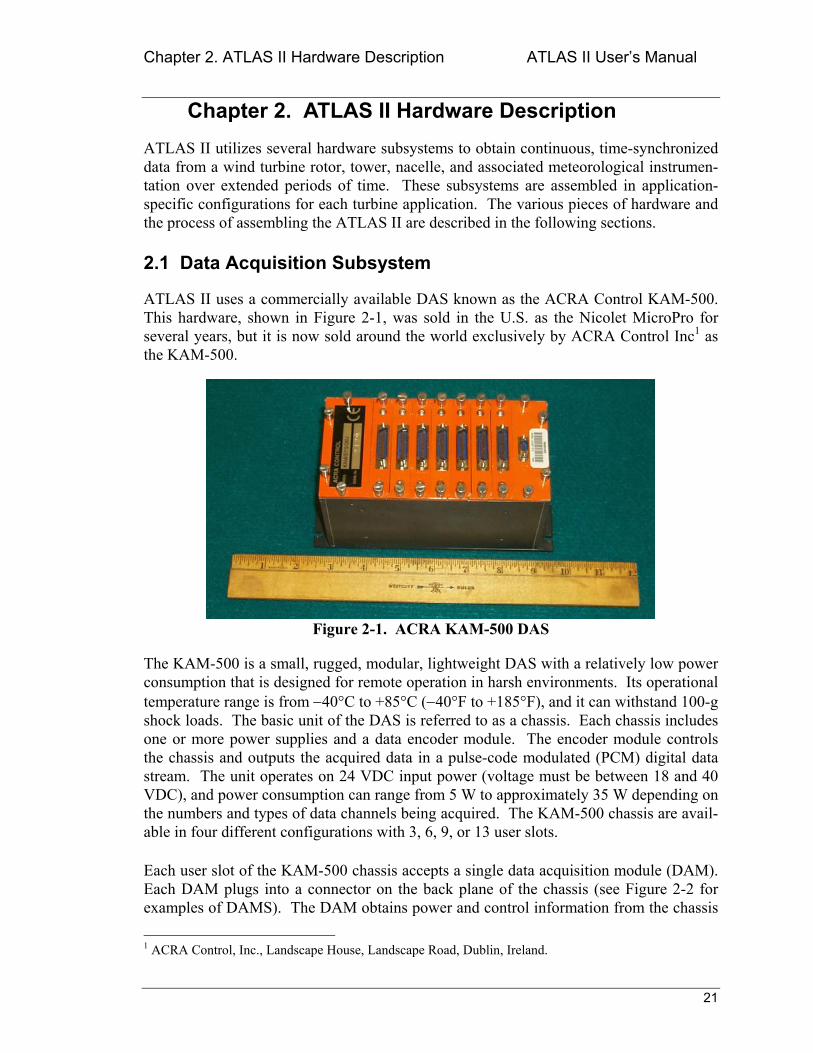
After all of the files have been copied to the computer, ATLAS II is ready to run for the first time. As part of the installation, ATLAS II will create a shortcut to the application that will appear in the Start>>Programs menu.
Chapter 1. ATLAS II Getting Started ATLAS II Users Manual
19
Figure 1-6. ATLAS II will ask the user to choose a folder. After a folder is chosen, click OK and then Next.
Figure 1-7. ATLAS II Displays the Information Entered. Click Install.
Chapter 1. ATLAS II Getting Started ATLAS II Users Manual
20
Figure 1-8. Actual installation of the files will take several seconds.
Figure 1-9. Window showing successful installation of ATLAS II.
Chapter 2. ATLAS II Hardware Description ATLAS II Users Manual
21
Chapter 2. ATLAS II Hardware Description ATLAS II utilizes several hardware subsystems to obtain continuous, time-synchronized data from a wind turbine rotor, tower, nacelle, and associated meteorological instrumen-tation over extended periods of time. These subsystems are assembled in application-specific configurations for each turbine application. The various pieces of hardware and the process of assembling the ATLAS II are described in the following sections.
2.1 Data Acquisition Subsystem
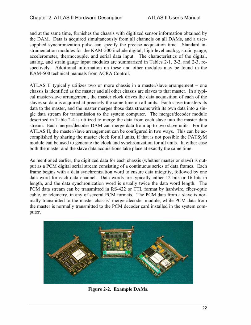
ATLAS II uses a commercially available DAS known as the ACRA Control KAM-500. This hardware, shown in Figure 2-1, was sold in the U.S. as the Nicolet MicroPro for several years, but it is now sold around the world exclusively by ACRA Control Inc1 as the KAM-500.
Figure 2-1. ACRA KAM-500 DAS
The KAM-500 is a small, rugged, modular, lightweight DAS with a relatively low power consumption that is designed for remote operation in harsh environments. Its operational temperature range is from −40°C to +85°C (−40°F to +185°F), and it can withstand 100-g shock loads. The basic unit of the DAS is referred to as a chassis. Each chassis includes one or more power supplies and a data encoder module. The encoder module controls the chassis and outputs the acquired data in a pulse-code modulated (PCM) digital data stream. The unit operates on 24 VDC input power (voltage must be between 18 and 40 VDC), and power consumption can range from 5 W to approximately 35 W depending on the numbers and types of data channels being acquired. The KAM-500 chassis are avail-able in four different configurations with 3, 6, 9, or 13 user slots.
Each user slot of the KAM-500 chassis accepts a single data acquisition module (DAM). Each DAM plugs into a connector on the back plane of the chassis (see Figure 2-2 for examples of DAMS). The DAM obtains power and control information from the chassis 1 ACRA Control, Inc., Landscape House, Landscape Road, Dublin, Ireland.
Chapter 2. ATLAS II Hardware Description ATLAS II Users Manual
22
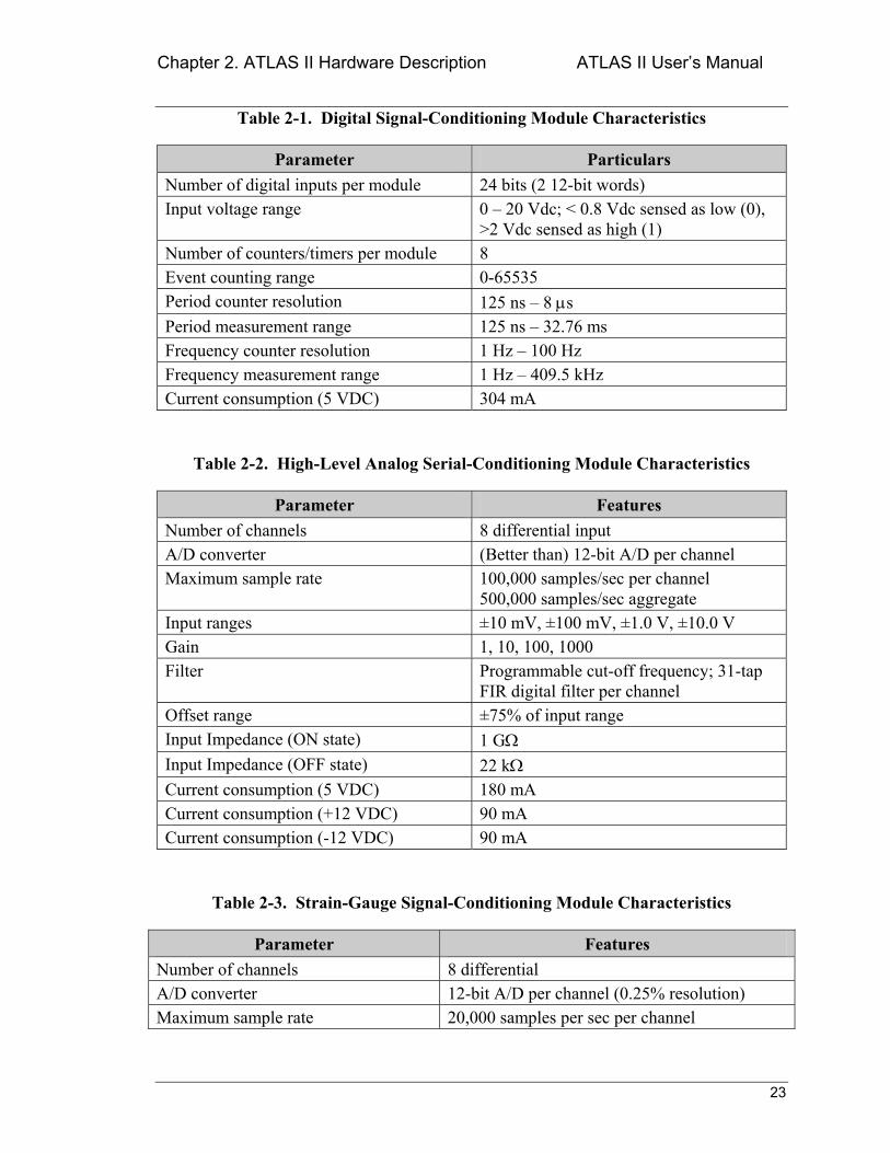
and at the same time, furnishes the chassis with digitized sensor information obtained by the DAM. Data is acquired simultaneously from all channels on all DAMs, and a user-supplied synchronization pulse can specify the precise acquisition time. Standard in-strumentation modules for the KAM-500 include digital, high-level analog, strain gauge, accelerometer, thermocouple, and serial data input. The characteristics of the digital, analog, and strain gauge input modules are summarized in Tables 2-1, 2-2, and 2-3, re-spectively. Additional information on these and other modules may be found in the KAM-500 technical manuals from ACRA Control.
ATLAS II typically utilizes two or more chassis in a master/slave arrangement one chassis is identified as the master and all other chassis are slaves to that master. In a typi-cal master/slave arrangement, the master clock drives the data acquisition of each of the slaves so data is acquired at precisely the same time on all units. Each slave transfers its data to the master, and the master merges those data streams with its own data into a sin-gle data stream for transmission to the system computer. The merger/decoder module described in Table 2-4 is utilized to merge the data from each slave into the master data stream. Each merger/decoder DAM can merge data from up to two slave units. For the ATLAS II, the master/slave arrangement can be configured in two ways. This can be ac-complished by sharing the master clock for all units, if that is not possible the PATSyM module can be used to generate the clock and synchronization for all units. In either case both the master and the slave data acquisitions take place at exactly the same time
As mentioned earlier, the digitized data for each chassis (whether master or slave) is out-put as a PCM digital serial stream consisting of a continuous series of data frames. Each frame begins with a data synchronization word to ensure data integrity, followed by one data word for each data channel. Data words are typically either 12 bits or 16 bits in length, and the data synchronization word is usually twice the data word length. The PCM data stream can be transmitted in RS-422 or TTL format by hardwire, fiber-optic cable, or telemetry, in any of several PCM formats. The PCM data from a slave is nor-mally transmitted to the master chassis merger/decoder module, while PCM data from the master is normally transmitted to the PCM decoder card installed in the system com-puter.
Figure 2-2. Example DAMs.
Chapter 2. ATLAS II Hardware Description ATLAS II Users Manual
23
Table 2-1. Digital Signal-Conditioning Module Characteristics
Parameter Particulars Number of digital inputs per module 24 bits (2 12-bit words) Input voltage range 0 20 Vdc; < 0.8 Vdc sensed as low (0),
>2 Vdc sensed as high (1) Number of counters/timers per module 8 Event counting range 0-65535 Period counter resolution 125 ns 8 µs Period measurement range 125 ns 32.76 ms Frequency counter resolution 1 Hz 100 Hz Frequency measurement range 1 Hz 409.5 kHz Current consumption (5 VDC) 304 mA
Table 2-2. High-Level Analog Serial-Conditioning Module Characteristics
Parameter Features Number of channels 8 differential input A/D converter (Better than) 12-bit A/D per channel Maximum sample rate 100,000 samples/sec per channel
500,000 samples/sec aggregate Input ranges ±10 mV, ±100 mV, ±1.0 V, ±10.0 V Gain 1, 10, 100, 1000 Filter Programmable cut-off frequency; 31-tap
FIR digital filter per channel Offset range ±75% of input range Input Impedance (ON state) 1 GΩ Input Impedance (OFF state) 22 kΩ Current consumption (5 VDC) 180 mA Current consumption (+12 VDC) 90 mA Current consumption (-12 VDC) 90 mA
Table 2-3. Strain-Gauge Signal-Conditioning Module Characteristics
Parameter Features Number of channels 8 differential A/D converter 12-bit A/D per channel (0.25% resolution) Maximum sample rate 20,000 samples per sec per channel
Chapter 2. ATLAS II Hardware Description ATLAS II Users Manual
24
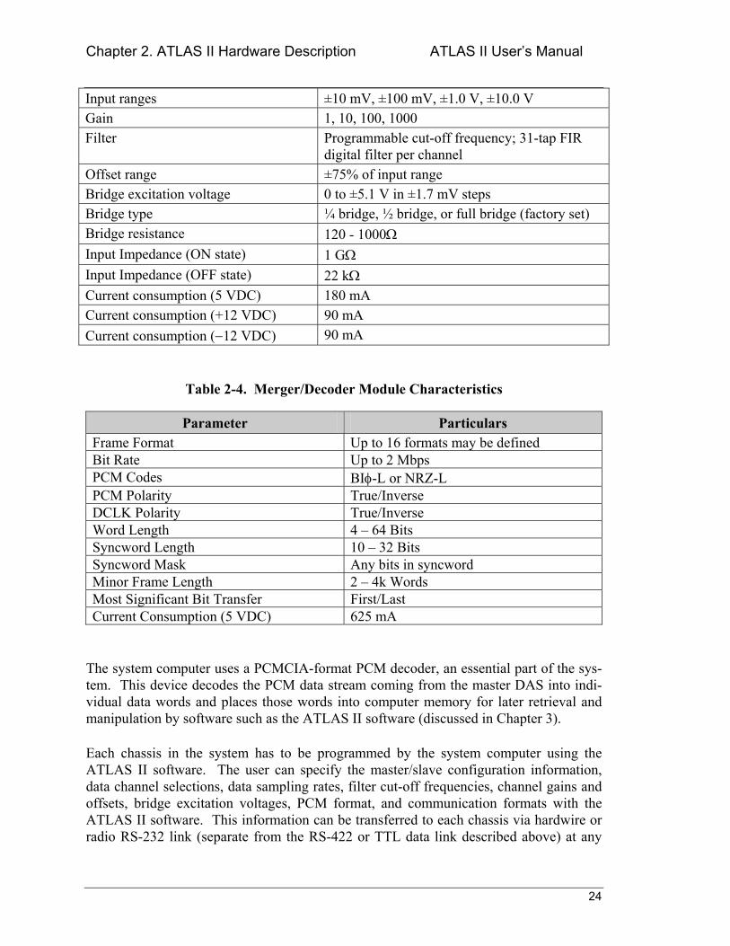
Input ranges ±10 mV, ±100 mV, ±1.0 V, ±10.0 V Gain 1, 10, 100, 1000 Filter Programmable cut-off frequency; 31-tap FIR
digital filter per channel Offset range ±75% of input range Bridge excitation voltage 0 to ±5.1 V in ±1.7 mV steps Bridge type ¼ bridge, ½ bridge, or full bridge (factory set) Bridge resistance 120 - 1000Ω Input Impedance (ON state) 1 GΩ Input Impedance (OFF state) 22 kΩ Current consumption (5 VDC) 180 mA Current consumption (+12 VDC) 90 mA Current consumption (−12 VDC) 90 mA
Table 2-4. Merger/Decoder Module Characteristics
Parameter Particulars Frame Format Up to 16 formats may be defined Bit Rate Up to 2 Mbps PCM Codes BIφ-L or NRZ-L PCM Polarity True/Inverse DCLK Polarity True/Inverse Word Length 4 64 Bits Syncword Length 10 32 Bits Syncword Mask Any bits in syncword Minor Frame Length 2 4k Words Most Significant Bit Transfer First/Last Current Consumption (5 VDC) 625 mA
The system computer uses a PCMCIA-format PCM decoder, an essential part of the sys-tem. This device decodes the PCM data stream coming from the master DAS into indi-vidual data words and places those words into computer memory for later retrieval and manipulation by software such as the ATLAS II software (discussed in Chapter 3).
Each chassis in the system has to be programmed by the system computer using the ATLAS II software. The user can specify the master/slave configuration information, data channel selections, data sampling rates, filter cut-off frequencies, channel gains and offsets, bridge excitation voltages, PCM format, and communication formats with the ATLAS II software. This information can be transferred to each chassis via hardwire or radio RS-232 link (separate from the RS-422 or TTL data link described above) at any
Chapter 2. ATLAS II Hardware Description ATLAS II Users Manual
25
time to actually program the various DAS units. Programming a chassis interrupts data acquisition for that unit, but the unit resumes acquisition immediately upon completion of programming.
2.1.1 DAS Chassis
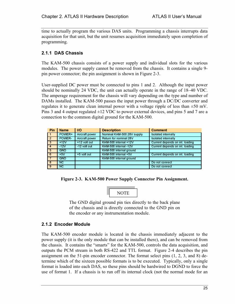
The KAM-500 chassis consists of a power supply and individual slots for the various modules. The power supply cannot be removed from the chassis. It contains a single 9-pin power connector; the pin assignment is shown in Figure 2-3.
User-supplied DC power must be connected to pins 1 and 2. Although the input power should be nominally 24 VDC, the unit can actually operate in the range of 1840 VDC. The amperage requirement for the chassis will vary depending on the type and number of DAMs installed. The KAM-500 passes the input power through a DC/DC converter and regulates it to generate clean internal power with a voltage ripple of less than ±50 mV. Pins 3 and 4 output regulated ±12 VDC to power external devices, and pins 5 and 7 are a connection to the common digital ground for the KAM-500.
Figure 2-3. KAM-500 Power Supply Connector Pin Assignment.
The GND digital ground pin ties directly to the back plane of the chassis and is directly connected to the GND pin on the encoder or any instrumentation module.
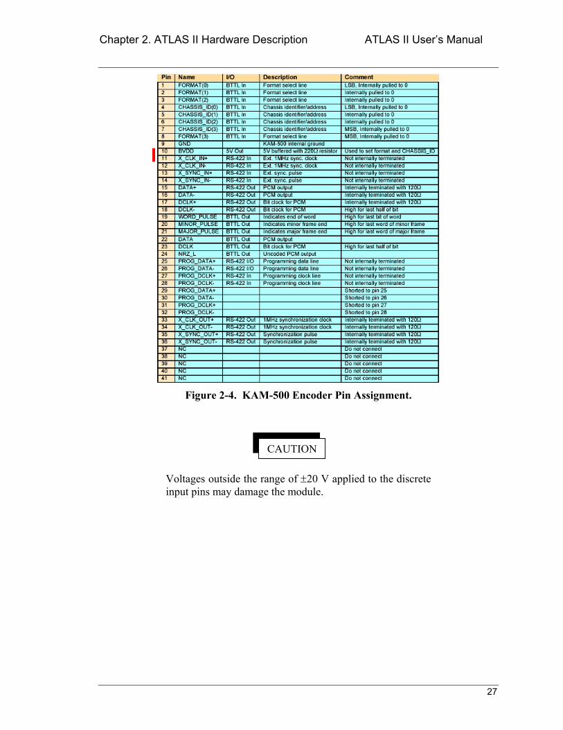
2.1.2 Encoder Module
The KAM-500 encoder module is located in the chassis immediately adjacent to the power supply (it is the only module that can be installed there), and can be removed from the chassis. It contains the smarts for the KAM-500, controls the data acquisition, and outputs the PCM stream in both RS-422 and TTL format. Figure 2-4 describes the pin assignment on the 51-pin encoder connector. The format select pins (1, 2, 3, and 8) de-termine which of the sixteen possible formats is to be executed. Typically, only a single format is loaded into each DAS, so these pins should be hardwired to DGND to force the use of format 1. If a chassis is to run off its internal clock (not the normal mode for an
NOTE
Chapter 2. ATLAS II Hardware Description ATLAS II Users Manual
26
ATLAS II application), pins 4-7 (the Chassis ID pins) are not to be connected. If a PAT-SyM is used in a chassis (as in an ATLAS II configuration), pins 11-14 are connected to the PATSyM connector (see Figure 2-12 for PATSyM pin assignment) to provide syn-chronization of data acquisition, and pins 4-7 must be hardwired to a +5 VDC source to force the DAS to accept the input from pins 11-14. If the ATLAS II system includes multiple slave chassis, make sure that a unique combination for the Chassis ID signals (think of these lines as an address) is used. Pins 22 and 23 output the PCM data stream in TTL mode. Pins 15-18 output the PCM data stream in RS-422 mode. Pins 25-28 pro-vide the interface signals needed to program the DAS.
Both RS-422 and TTL PCM data streams are output by the KAM-500, regardless of whether the RS-422 or TTL com-munications mode is specified when programming the DAS with the ATLAS II software.
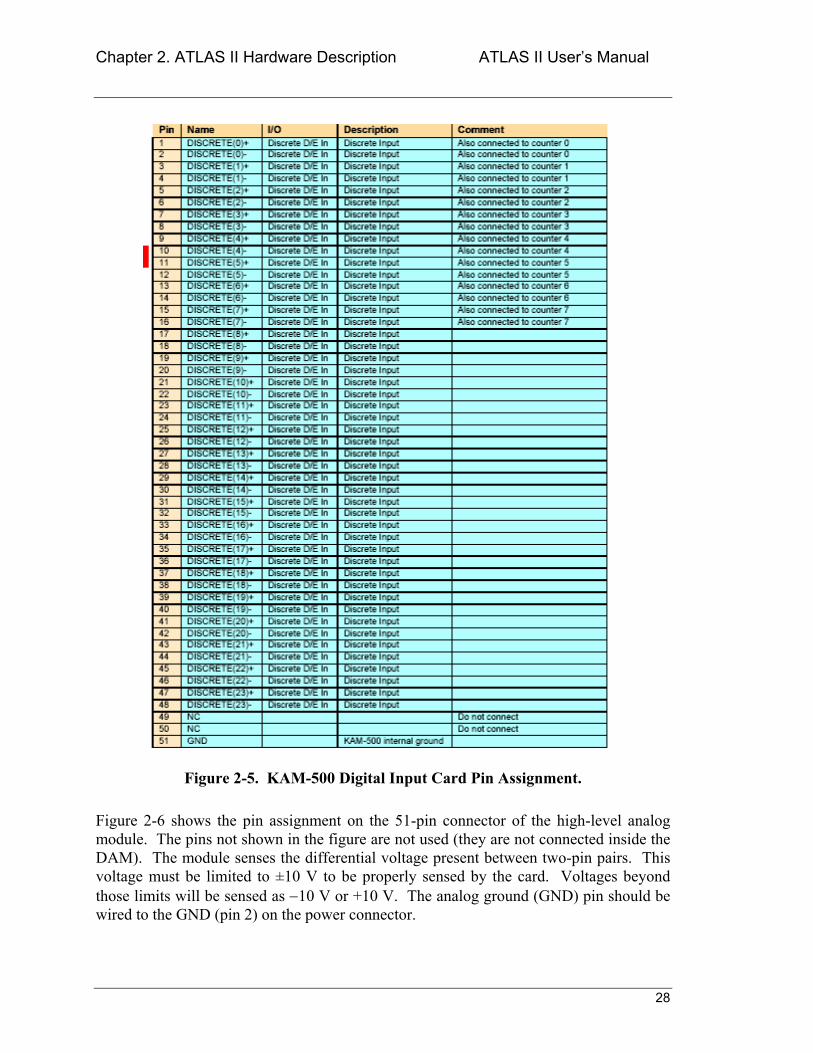
2.1.3 Instrumentation Modules
As mentioned above, the instrumentation modules typically used in ATLAS II include the digital, high-level analog, and strain-gauge modules. Figure 2-5 describes the pin as-signment on the 51-pin connector of the digital input module. Pins 148 are treated as discrete input lines. A voltage level below 0.8 VDC is interpreted as 0 and a voltage level of 2.0 VDC or higher is interpreted as 1. Avoid voltages in the 0.8 2.0 V range as their interpretation is undefined, i.e., they could be interpreted as either a logic 1 or a logic 0. Maximum allowable voltage levels are ±20 VDC. The DGND pin (pin 51) is connected to the chassis back plane and to the DGND pin of any other DAS connector.
NOTE
Chapter 2. ATLAS II Hardware Description ATLAS II Users Manual
27
Figure 2-4. KAM-500 Encoder Pin Assignment.
Voltages outside the range of ±20 V applied to the discrete input pins may damage the module.
CAUTION
Chapter 2. ATLAS II Hardware Description ATLAS II Users Manual
28
Figure 2-5. KAM-500 Digital Input Card Pin Assignment.
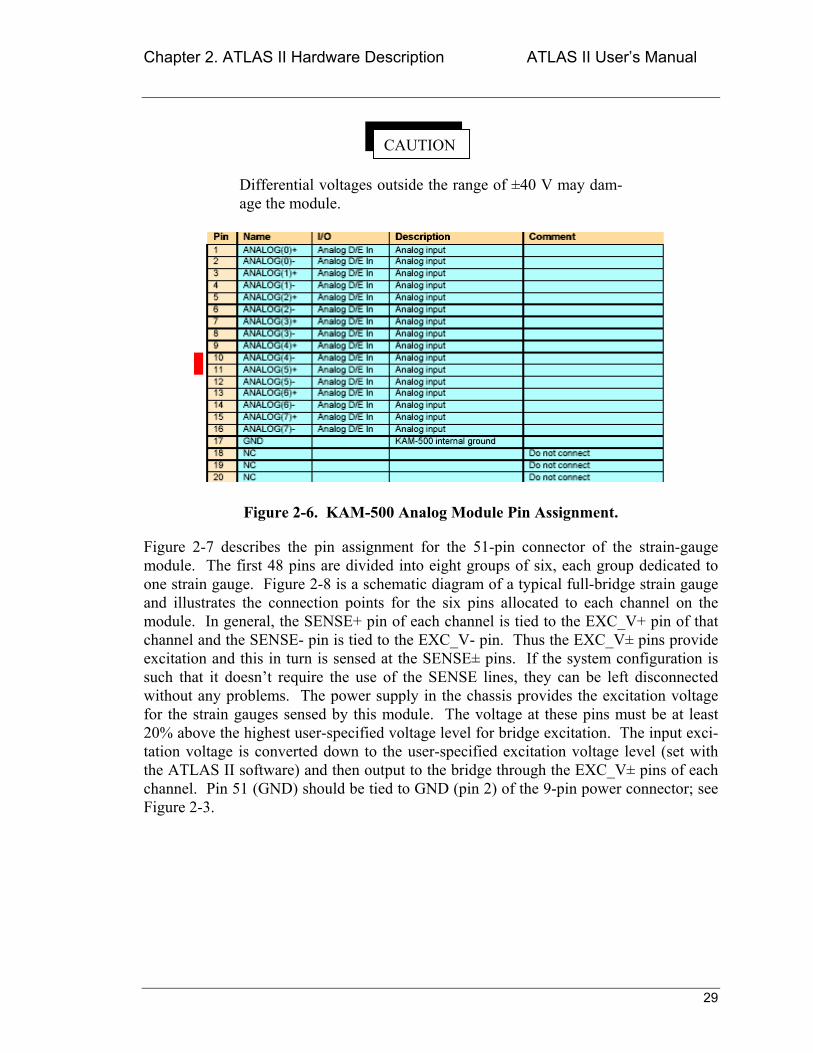
Figure 2-6 shows the pin assignment on the 51-pin connector of the high-level analog module. The pins not shown in the figure are not used (they are not connected inside the DAM). The module senses the differential voltage present between two-pin pairs. This voltage must be limited to ±10 V to be properly sensed by the card. Voltages beyond those limits will be sensed as −10 V or +10 V. The analog ground (GND) pin should be wired to the GND (pin 2) on the power connector.
Chapter 2. ATLAS II Hardware Description ATLAS II Users Manual
29
CAUTION
Differential voltages outside the range of ±40 V may dam-age the module.
Figure 2-6. KAM-500 Analog Module Pin Assignment.
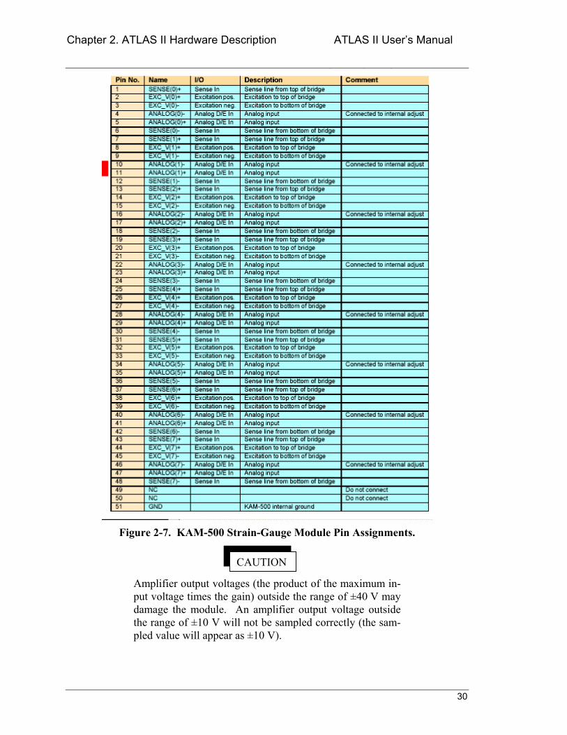
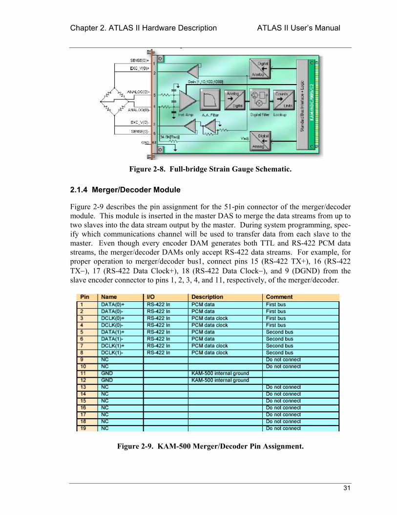
Figure 2-7 describes the pin assignment for the 51-pin connector of the strain-gauge module. The first 48 pins are divided into eight groups of six, each group dedicated to one strain gauge. Figure 2-8 is a schematic diagram of a typical full-bridge strain gauge and illustrates the connection points for the six pins allocated to each channel on the module. In general, the SENSE+ pin of each channel is tied to the EXC_V+ pin of that channel and the SENSE- pin is tied to the EXC_V- pin. Thus the EXC_V± pins provide excitation and this in turn is sensed at the SENSE± pins. If the system configuration is such that it doesnt require the use of the SENSE lines, they can be left disconnected without any problems. The power supply in the chassis provides the excitation voltage for the strain gauges sensed by this module. The voltage at these pins must be at least 20% above the highest user-specified voltage level for bridge excitation. The input exci-tation voltage is converted down to the user-specified excitation voltage level (set with the ATLAS II software) and then output to the bridge through the EXC_V± pins of each channel. Pin 51 (GND) should be tied to GND (pin 2) of the 9-pin power connector; see Figure 2-3.
Chapter 2. ATLAS II Hardware Description ATLAS II Users Manual
30
CAUTION
Figure 2-7. KAM-500 Strain-Gauge Module Pin Assignments.
Amplifier output voltages (the product of the maximum in-put voltage times the gain) outside the range of ±40 V may damage the module. An amplifier output voltage outside the range of ±10 V will not be sampled correctly (the sam-pled value will appear as ±10 V).
Chapter 2. ATLAS II Hardware Description ATLAS II Users Manual
31
Figure 2-8. Full-bridge Strain Gauge Schematic.
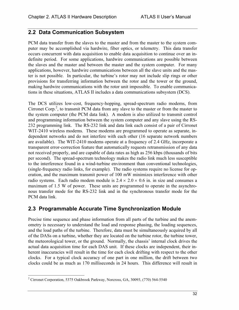
2.1.4 Merger/Decoder Module
Figure 2-9 describes the pin assignment for the 51-pin connector of the merger/decoder module. This module is inserted in the master DAS to merge the data streams from up to two slaves into the data stream output by the master. During system programming, spec-ify which communications channel will be used to transfer data from each slave to the master. Even though every encoder DAM generates both TTL and RS-422 PCM data streams, the merger/decoder DAMs only accept RS-422 data streams. For example, for proper operation to merger/decoder bus1, connect pins 15 (RS-422 TX+), 16 (RS-422 TX−), 17 (RS-422 Data Clock+), 18 (RS-422 Data Clock−), and 9 (DGND) from the slave encoder connector to pins 1, 2, 3, 4, and 11, respectively, of the merger/decoder.
Figure 2-9. KAM-500 Merger/Decoder Pin Assignment.
Chapter 2. ATLAS II Hardware Description ATLAS II Users Manual
32
2.2 Data Communication Subsystem
PCM data transfer from the slaves to the master and from the master to the system com-puter may be accomplished via hardwire, fiber optics, or telemetry. This data transfer occurs concurrent with data acquisition to enable data acquisition to continue over an in-definite period. For some applications, hardwire communications are possible between the slaves and the master and between the master and the system computer. For many applications, however, hardwire communications between all the slave units and the mas-ter is not possible. In particular, the turbines rotor may not include slip rings or other provisions for transferring information between the rotor and the tower or the ground, making hardwire communications with the rotor unit impossible. To enable communica-tions in these situations, ATLAS II includes a data communications subsystem (DCS).
The DCS utilizes low-cost, frequency-hopping, spread-spectrum radio modems, from Cirronet Corp.2, to transmit PCM data from any slave to the master or from the master to the system computer (the PCM data link). A modem is also utilized to transmit control and programming information between the system computer and any slave using the RS-232 programming link. The RS-232 link and data link each consist of a pair of Cirronet WIT-2410 wireless modems. These modems are programmed to operate as separate, in-dependent networks and do not interfere with each other (16 separate network numbers are available). The WIT-2410 modems operate at a frequency of 2.4 GHz, incorporate a transparent error-correction feature that automatically requests retransmission of any data not received properly, and are capable of data rates as high as 256 kbps (thousands of bits per second). The spread-spectrum technology makes the radio link much less susceptible to the interference found in a wind-turbine environment than conventional technologies, (single-frequency radio links, for example). The radio systems require no license for op-eration, and the maximum transmit power of 100 mW minimizes interference with other radio systems. Each radio modem module is 2.4 × 2.0 × 0.6 in. in size and consumes a maximum of 1.5 W of power. These units are programmed to operate in the asynchro-nous transfer mode for the RS-232 link and in the synchronous transfer mode for the PCM data link.
2.3 Programmable Accurate Time Synchronization Module
Precise time sequence and phase information from all parts of the turbine and the anem-ometry is necessary to understand the load and response phasing, the loading sequences, and the load paths of the turbine. Therefore, data must be simultaneously acquired by all of the DASs on a turbine, whether they are located on the turbine rotor, the turbine tower, the meteorological tower, or the ground. Normally, the chassis internal clock drives the actual data acquisition time for each DAS unit. If these clocks are independent, their in-herent inaccuracies will result in the time for each clock drifting with respect to the other clocks. For a typical clock accuracy of one part in one million, the drift between two clocks could be as much as 170 milliseconds in 24 hours. This difference will result in
2 Cirronet Corporation, 5375 Oakbrook Parkway, Norcross, GA, 30093, (770) 564-5540
Chapter 2. ATLAS II Hardware Description ATLAS II Users Manual
33
data acquisition at different absolute times for each DAS unit and can make time correla-tion of the data from the various DAS units difficult.
To maintain very accurate clock synchronization between the DAS units over long peri-ods of time, ATLAS II utilizes the GPS system. In normal operating mode, each GPS satellite continually transmits its orbital parameters, along with the precise universal time clock (UTC). GPS receivers decode that information and utilize triangulation techniques to accurately determine their position and UTC. The internal clock in each GPS receiver is continually adjusted to keep it in agreement with UTC. If the DAS clocks are slaved to GPS receiver time (UTC), they will not drift with respect to each other.
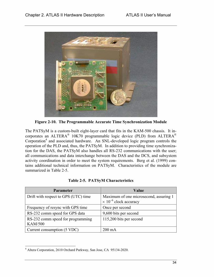
The Programmable Accurate Time Synchronization Module (PATSyM), developed by Sandia National Laboratories (SNL) specifically for the ATLAS II application, utilizes a commercial Jupiter GPS receiver3 to do exactly that. As long as the Jupiter antenna is receiving signals from three or more GPS satellites, the receiver will remain synchro-nized with UTC within ±1 µs. Thus, the clocks in two of these receivers will vary with respect to each other by a maximum of 2 µs, regardless of how long they have been oper-ating. The Jupiter receiver also generates a one pulse per second (1PPS) signal, with the rising edge of the pulse occurring exactly on the UTC second. The PATSyM, shown in Figure 2-10, utilizes this 1PPS signal to generate two clock pulse trains that are precisely synchronized to UTC. These pulse trains control the actual data acquisition times of all the DAS units, forcing them to acquire data within 2 µs of each other, indefinitely. The actual data acquisition time, accurate to ±1 µs, is available from each PATSyM and can be included in the PCM data stream (i.e., the data from each DAS can be time-stamped). This information can then be used to associate the data acquired by one DAS at a specific time with the data acquired by other DASs at that same time. In practice, using modems to transfer data from the rotor delays the data by one sample period (for 30 Hz data) the rotor data received in a data frame usually corresponds to the ground-based data received one sample data frame earlier.
3 Conexant Systems, Inc., 4311 Jamboree Road, P.O. Box C, Newport Beach, CA, 92658-8902, (949) 483-4600.
Chapter 2. ATLAS II Hardware Description ATLAS II Users Manual
34
Figure 2-10. The Programmable Accurate Time Synchronization Module
The PATSyM is a custom-built eight-layer card that fits in the KAM-500 chassis. It in-corporates an ALTERA® 10K70 programmable logic device (PLD) from ALTERA Corporation4 and associated hardware. An SNL-developed logic program controls the operation of the PLD and, thus, the PATSyM. In addition to providing time synchroniza-tion for the DAS, the PATSyM also handles all RS-232 communications with the user; all communications and data interchange between the DAS and the DCS, and subsystem activity coordination in order to meet the system requirements. Berg et al. (1999) con-tains additional technical information on PATSyM. Characteristics of the module are summarized in Table 2-5.
Table 2-5. PATSyM Characteristics
Parameter Value Drift with respect to GPS (UTC) time Maximum of one microsecond, assuring 1
× 10−6 clock accuracy Frequency of resync with GPS time Once per second RS-232 comm speed for GPS data 9,600 bits per second RS-232 comm speed for programming KAM/500
115,200 bits per second
Current consumption (5 VDC) 200 mA
4 Altera Corporation, 2610 Orchard Parkway, San Jose, CA 95134-2020.
Chapter 2. ATLAS II Hardware Description ATLAS II Users Manual
35
The GPS receiver in each PATSyM must be connected to an antenna with a generally unobstructed view of the sky. The GPS signals will pass through small amounts of com-mon building materials, such as glass, wood, brick, and concrete block, but will usually not pass through metal objects. A general rule of thumb is that the GPS antenna must be mounted outside of any building, but some antennas may work inside some buildings. The receiver requires signal reception from at least three satellites before it can synchro-nize, or lock, its internal clock to UTC. Even if the antenna is placed so it has an unob-structed view of the sky, a receiver may take as long as five minutes to acquire lock after the receiver power is turned on. Keep in mind that an antennas must be mounted on the rotor to provide GPS signals to the RBU. The ability of the rotor-mounted GPS receiver to retain satellite communications and time lock is dependent on both the antenna rota-tion speed and antenna configuration. A half-wavelength antenna configuration (about 3 in. in diameter) is adequate for maintaining time lock at rotation speeds as high as 350 rpm. Experience has shown that an antenna mounted on a non-rotating wind-turbine ro-tor will usually lock onto six or more satellites. As the antenna rotation speed is gradu-ally increased, the number of satellites that the receiver is locked onto gradually decreases. At 350 rpm, the receiver is usually locked onto only three or four satellites at any one time, and the actual satellites in lock change frequently (perhaps every revolu-tion). Momentary satellite communication dropouts, which might occur during brief pe-riods of higher rotation speed, are not a problem because the clock in the receiver will continue to run and produce the 1PPS signal, although that clock will slowly drift with respect to UTC. Once the antenna rpm drops to 350 or less, the receiver will reestablish communications with three or more satellites, and the receiver clock will be quickly relocked to UTC time. SNL has always mounted the rotor antenna so that its axis of rota-tion coincides with the rotor axis of rotation to minimize rotation-caused motion. An-tenna wobble due to mounting the antenna so that its axis is offset several centimeters from the rotor axis is not expected to cause loss of lock at low rpm (100 rpm or below), but this has not been verified. It is important that the antenna be mounted so it always has an unobstructed view of the sky throughout its rotation.
Be sure that each GPS receiver is receiving messages from at least three satellites, because only then is the internal clock locked to the UTC. The status of each GPS receiver can be determined by monitoring the GPS output from that receiver (see Section 3.13.1 PATSyM Diagnostics Util-ity).
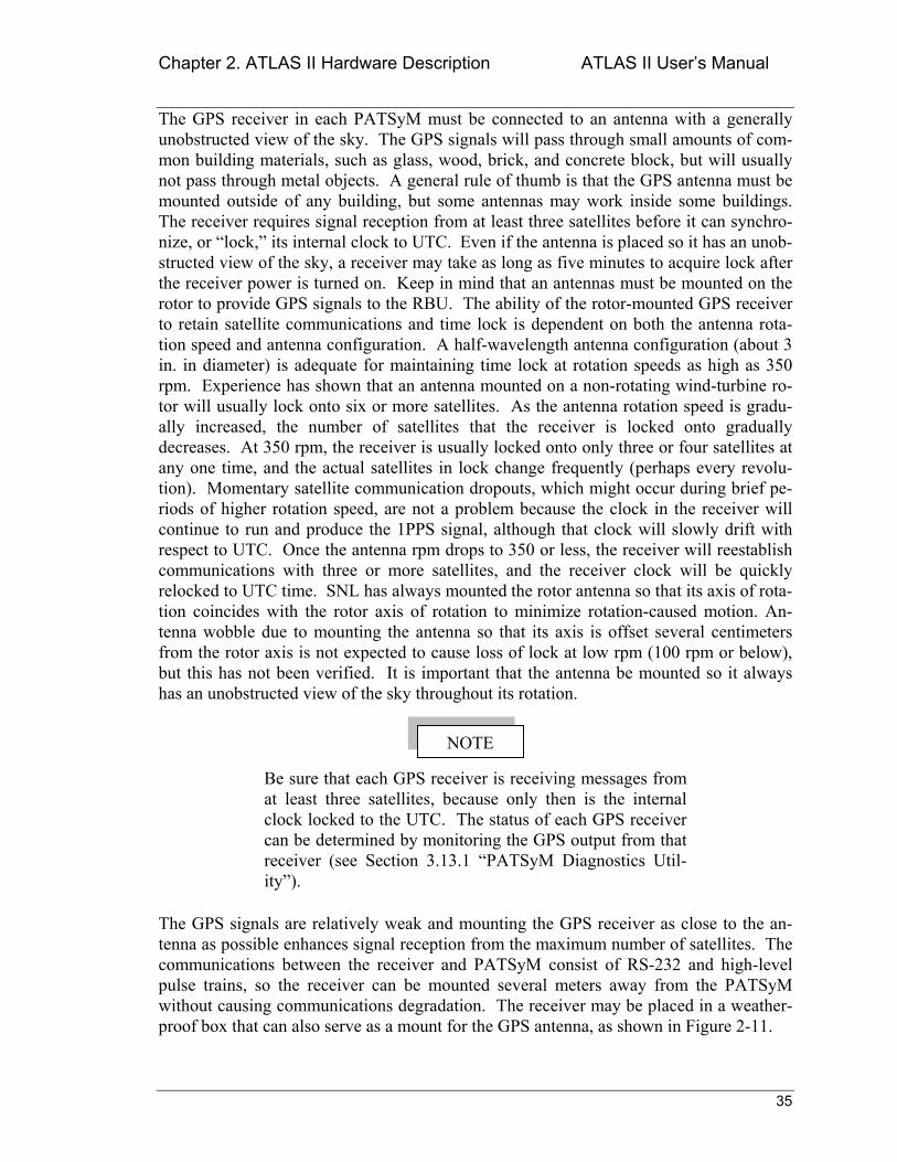
The GPS signals are relatively weak and mounting the GPS receiver as close to the an-tenna as possible enhances signal reception from the maximum number of satellites. The communications between the receiver and PATSyM consist of RS-232 and high-level pulse trains, so the receiver can be mounted several meters away from the PATSyM without causing communications degradation. The receiver may be placed in a weather-proof box that can also serve as a mount for the GPS antenna, as shown in Figure 2-11.
NOTE
Chapter 2. ATLAS II Hardware Description ATLAS II Users Manual
36
Figure 2-11. GPS Receiver/Antenna Configuration.
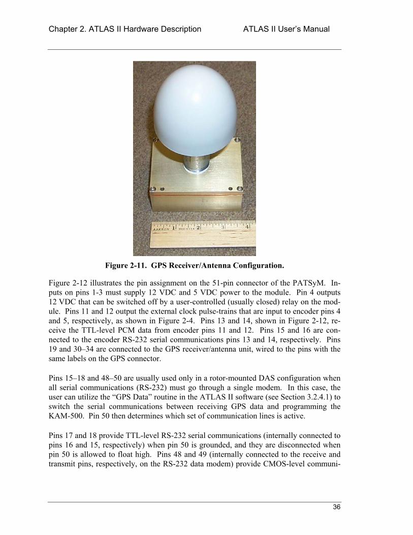
Figure 2-12 illustrates the pin assignment on the 51-pin connector of the PATSyM. In-puts on pins 1-3 must supply 12 VDC and 5 VDC power to the module. Pin 4 outputs 12 VDC that can be switched off by a user-controlled (usually closed) relay on the mod-ule. Pins 11 and 12 output the external clock pulse-trains that are input to encoder pins 4 and 5, respectively, as shown in Figure 2-4. Pins 13 and 14, shown in Figure 2-12, re-ceive the TTL-level PCM data from encoder pins 11 and 12. Pins 15 and 16 are con-nected to the encoder RS-232 serial communications pins 13 and 14, respectively. Pins 19 and 3034 are connected to the GPS receiver/antenna unit, wired to the pins with the same labels on the GPS connector.
Pins 1518 and 4850 are usually used only in a rotor-mounted DAS configuration when all serial communications (RS-232) must go through a single modem. In this case, the user can utilize the GPS Data routine in the ATLAS II software (see Section 3.2.4.1) to switch the serial communications between receiving GPS data and programming the KAM-500. Pin 50 then determines which set of communication lines is active.
Pins 17 and 18 provide TTL-level RS-232 serial communications (internally connected to pins 16 and 15, respectively) when pin 50 is grounded, and they are disconnected when pin 50 is allowed to float high. Pins 48 and 49 (internally connected to the receive and transmit pins, respectively, on the RS-232 data modem) provide CMOS-level communi-
Chapter 2. ATLAS II Hardware Description ATLAS II Users Manual
37
cations signals (internally connected to pins 16 and 15, respectively) when pin 50 is al-lowed to float high, and they are disconnected when pin 50 is grounded.
Pin # Pin Name Pin Description1 +5V 5 V input2 DGND Digital ground3 +12V 12 V input4 +12V_SWITCH Switched 12 V output5 NC Do not connect6 NC Do not connect7 NC Do not connect8 NC Do not connect9 NC Do not connect
10 NC Do not connect11 EXT_SYNC External sync pulse output12 EXT_CLK External clock pulse output13 PCM_DATA PCM data input (in user-specified code)14 DCLK Data clock input15 S_IN2 RS-232 transmit from encoder, input16 S_OUT2 RS-232 receive to encoder, output17 S_IN1 RS-232 input from hardwire connection18 S_OUT1 RS-232 output to hardwire connection19 GPS_TX RS-232 link to GPS receiver, output20 NC Do not connect . 29 NC Do not connect30 PWR_IN 5V switched power for GPS receiver,
output31 M_RST Master reset for GPS receiver, output32 1_PPS 1 pulse per second from GPS receiver,
input33 10_HZ_GPS 10 Hz pulse train from GPS receiver, input34 GPS_RX RS-232 line to GPS receiver, input35 NC Do not connect . 47 NC Do not connect48 USIN2 CMOS-level RS-232 input from modem49 USOUT2 CMOS-level RS-232 output to modem50 TTL/RS232 User-select switch for CMOS/RS-232
selection, input51 NC Do not connect
Connector: 51-pin micro-miniature, femaleMating Connector: MDM-51P
Figure 2-12. PATSyM Pin Assignment.
Chapter 2. ATLAS II Hardware Description ATLAS II Users Manual
38
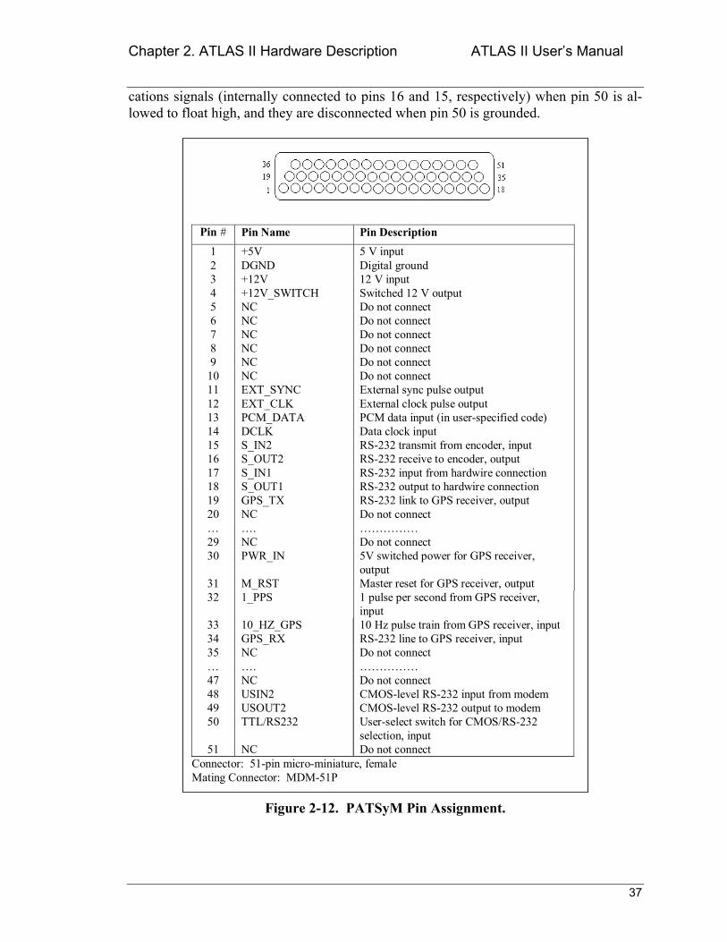
Figure 2-13 illustrates the pin assignment for the 13-pin connector on the GPS an-tenna/receiver box. Pin 1 should be connected to a constant source of 5 VDC. This maintains the GPS satellite information when the antenna/receiver unit is placed in the sleep mode. Pin 2 must be connected to the DAS digital ground. Pins 3 and 4 provide RS-232 communication between the GPS receiver and the PATSyM. Pin 5 causes a mas-ter reset of the GPS (a cold start) when tied to ground. Pin 6 is the time mark 1PPS used by PATSyM to synchronize the generated pulse trains to UTC, and pin 7 is a 10 kHz pulse train output by the GPS receiver. Pin 8 is the primary power supply to the GPS. When this is pulled to ground, the GPS receiver and antenna shut down. If power is sup-plied on pin 1 during this time, the system will come up much quicker than would be the case if pin 1 were not kept high because the satellite location table is kept current.
Pin # Pin Name Pin Description
1 +5V +5 VDC power input (stay-alive power))2 DGND Digital ground3 GPS_TX GPS RS-232 transmission4 GPS_RX- GPS RS-232 receive5 M_RST Master reset (active low)6 1_PPS One pulse per second time mark output7 10kHz_GPS 10 KHz clock output8 PWR_IN Primary +5 VDC power input9 NC Do not connect
10 NC Do not connect11 NC Do not connect12 NC Do not connect13 NC Do not connect
Connector: 13-pin miniature circular shell , femaleSource: C ANNON Part number: JT07H-10-13S
Figure 2-13. GPS Antenna/Receiver Pin Assignment.
2.4 Lightning Protection Equipment
DAS units and all other ATLAS II components are susceptible to damage from high volt-ages due to lightning or other types of electrostatic discharge (ESD). It is important to include over-voltage protection for these components. The Citel E280-6V and-12V
Chapter 2. ATLAS II Hardware Description ATLAS II Users Manual
39
lightning protection modules from Citel Corporation5 have worked well for the ATLAS II. Specification sheets on this product may be found in Appendix A. Each module sup-plies protection for two pairs of signal lines at a cost of $4050 per module.
The Citel units contain both a quick-switching silicon avalanche diode and a gas tube be-tween the lines being protected and ground, along with a small resistor that causes cur-rent to flow through the gas tube when it is switched. The avalanche diode provides quick response to an electrostatic discharge such as lightning, but it cannot discharge much power. The gas tube, on the other hand, does not switch quickly and needs a volt-age potential of about 100 V to fire, but it can discharge large amounts of power. The Citel specification sheet claims a response time of less than 1 nanosecond, with a peak current capacity of 10 kA for these units. If one of these devices is placed in series in the bridge excitation line for a strain-gauge instrumentation module, the current drawn by the bridge (a few milliamps) will create a small voltage drop across that resistor. That volt-age drop will result in an excitation voltage at the strain-gauge bridge that is lower than that specified by the user during system configuration; a significant problem in some ap-plications. The bridge signal lines, however, carry very little current, so the voltage drop due to the resistor in a Citel device placed in the signal line is very small. Thus the Citel devices can easily be used to protect these lines. The Citels are used to protect all of the bridge lines, but they are connected as a shunt to ground (the line from the instrumenta-tion module to the bridge is connected to the line terminal on the Citel unit) on the excita-tion lines and in series (the lead from the instrumentation module is connected to the equipment side of the Citel unit and the lead to the bridge is connected to the line side of the Citel) on the signal lines. These connections are illustrated in the wiring schematic for the LIST units in Appendices B and C. In these configurations, the Citel devices can protect the bridge excitation lines from over-voltage events with up to 85 A currents, and the signal lines are protected for up to 10,000 A currents. While the 10,000 A protection should be sufficient for protection against most direct lightning strikes, the 85 A protec-tion certainly is not it does, however, offer protection from handling-induced ESD.
If the Citels do trigger, they will automatically reset as soon as the voltage level drops to normal operating voltage, and they will provide protection against future over-voltage effects. However, the gas tubes tend to lose their charge over a period of time and even-tually they cease to provide protection, so each module should be tested to ensure that it functions properly every two to three years.
Another device that appears to be well suited for providing general over-voltage protec-tion: is the SIDACtor, made by Teccor Electronics, Inc.6 These small devices have a very high off-state impedance, but turn on quickly (within 5 ns) when their break-over voltage is exceeded. They do not require the insertion of a resistor in a line in order to protect that line. In the on state, they create a short to ground, preventing high voltage from reaching the protected device, and they remain in this state until the current drops
5 Citel Corporation, 1111 Park Centre Boulevard, Suite 340, Miami, FL 33169, (305) 621-0022, www.citelprotection.com 6 Teccor Electronis, Inc, 1800 Hurd Drive, Irving, TX 75038, (972) 580-7777, www.teccor.com
Chapter 2. ATLAS II Hardware Description ATLAS II Users Manual
40
below a holding value. Their protection capability does not deteriorate with time. These devices can shunt approximately 200500 A to ground for short periods of time. They provide more protection than is provided by the Citel devices on the bridge excitation lines, but much lower than the protection provided by the Citel devices on the bridge sig-nal lines. It should be sufficient to protect against most over-voltage events, such as ESD or nearby lightning, but probably will not protect against a direct lighting hit. However, the Citel modules may also prove to be inadequate in case of a direct lightning hit. In the two years that ATLAS II has been deployed at the Bushland, TX site, numerous thunder-storms have occurred in the immediate vicinity, but no direct lightning hits on the system have occurred. These devices should be considered for lightning protection, as they are much smaller than the Citels, do not degrade over time, and do not cause a voltage drop in the line being protected, regardless of the amount of current flowing through that line.
2.5 Power Supplies
A DAS power supply must not only supply power for the DAS and the instrumentation modules contained within it, but it must also supply power the PATSyM module, and perhaps supply excitation to the analog instrumentation being monitored, depending on the particular application. If telemetry is used, the RBU power supply must also power two independent modems. The strain gauge and analog excitation can be supplied through the KAM-500 (within the limits listed on the specification sheet), or directly from the power supply. As noted above, the strain-gauge instrumentation module has two pins for bridge excitation input. The voltage at these inputs must be at least 20% above the highest user-specified level for bridge excitation. This voltage is converted down to the user-specified bridge-excitation voltage level and then output to the actual bridge through the 51-pin module connector (see the connector pin assignment in Figure 2-7). Information on estimating the power supply requirements for the DAS may be found in Appendix D. Pick a power supply that can supply more current than the amount needed, to allow for the possible addition of more instrumentation. Power supply size and weight are of much more importance for an RBU than for a GBU, due to size con-straints.
If a switching power supply is used, do not connect multi-ple units in parallel to achieve the necessary current the feedback circuits in the power supplies will buck each other and the resultant voltage and current output levels will be unstable.
The power supply voltage for the DAS can range from 18 to 40 VDC. Noise regulation of the power supply is not particularly important if all of the power is to be passed through the KAM-500, as the KAM-500 filters the incoming power. However, if the power supply is to provide instrument excitation voltage directly (rather than through the KAM-500 voltage output lines), the power supply should be regulated to ±50 mVDC or better. The COSEL MMB75A-2 24 VDC power supply has worked well for this
NOTE
Chapter 2. ATLAS II Hardware Description ATLAS II Users Manual
41
application. This unit operates off 110 VAC, single phase, and supplies two 12 VDC outputs; one with 3 A of output, the other with 1.5 A of output. By connecting the negative side of the 3 A output to the positive side of the 1.5 A output, the output votages can be changed to +24 VDC (3 A) and 24 VDC (1.5 A). This unit provides enough current to power most DAS configurations.
2.6 Connectors
Connectors are needed to connect the DAS units with data, communication, and power lines. The following description describes the approach taken when designing and select-ing the connectors for these units.
Using the same connectors for both indoor- and outdoor-mounted units makes it easy to interchange units, minimizes the number of connector configurations required, and mini-mizes the number of test cables needed. The cylindrical military/aerospace weatherproof connectors supplied by ITT Cannon, AMP, and other connector manufacturers offer good quality at reasonable prices. Using JT07-14-18S (bulkhead connector)/JT06-14-18P (ca-ble connector) 18 pin connectors and JT07-12-98S (bulkhead connector)/JT06-12-98P (cable connector) 10 pin connectors to connect strain gauge signals to the DAS units works quite well. The same connectors (JT07-14-18P for bulkhead/JT06-14-18S for ca-ble, etc.), in reverse polarity, are used to connect all analog signals. Although these con-nector pairs contain the same number of pins, the connector polarity is reversed between the strain-gauge connectors and the analog connectors. For the strain gauge connections, the cable connector contains pins. For the analog connections, the cable connector con-tains sockets. The difference in polarity prevents possible damage to instrumentation and DAMs due to accidental connection of strain gauge DAMs to analog instrumentation and vice versa. JT07-16-26S/JT06-16-26P 16-pin connector pairs work well for digital input. A JT07-8-3P/JT06-8-3S (3-pin) connector works well for the AC power connection, JT07-10-13P/JT06-10-13S (13 pin) connectors for the GPS antenna connection, and LJT07-11-13S/LJT06-11-13P (13-pin) connectors for the communications cable connec-tion. These connectors are readily available from Spacecraft Components Corporation7. Connections to the KAM-500 power and signal lines require the use of female subminia-ture D connectors in 9, 15, and 51-pin configurations. Pre-wired cables with these con-nectors are marketed by Cinch and Cannon and are commercially available.
2.7 ATLAS II Application-Specific Configuration
2.7.1 Application Planning
The hardware components of ATLAS II can be configured in many different ways to tai-lor the system to specific applications. The first step in assembling an ATLAS II for a new application is to determine the hardware needed for the particular application and separate that hardware into the distinct data acquisition units. The RBU contains the ac-
7 Spacecraft Components Corporation, 14137 Chadron Avenue, Box Number 5027, Hawthorne, CA 90251, (310) 973-6400.
Chapter 2. ATLAS II Hardware Description ATLAS II Users Manual
42
quisition hardware that will be mounted on and rotate with the turbine rotor. The GBUs contain the rest of the acquisition hardware; that hardware which will be mounted on the meteorological tower, the nacelle, the turbine tower, the turbine base, and perhaps other turbine components.
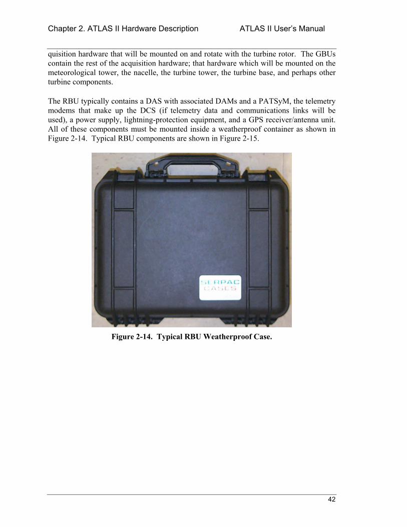
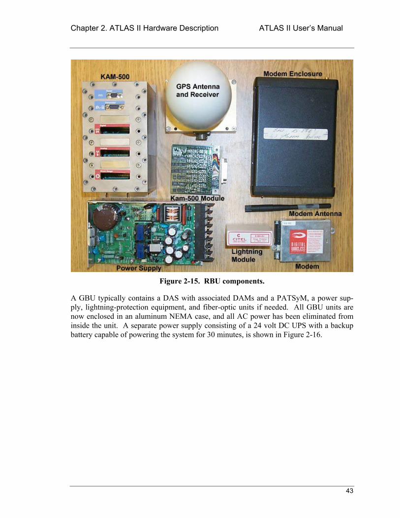
The RBU typically contains a DAS with associated DAMs and a PATSyM, the telemetry modems that make up the DCS (if telemetry data and communications links will be used), a power supply, lightning-protection equipment, and a GPS receiver/antenna unit. All of these components must be mounted inside a weatherproof container as shown in Figure 2-14. Typical RBU components are shown in Figure 2-15.
Figure 2-14. Typical RBU Weatherproof Case.
Chapter 2. ATLAS II Hardware Description ATLAS II Users Manual
43
Figure 2-15. RBU components.
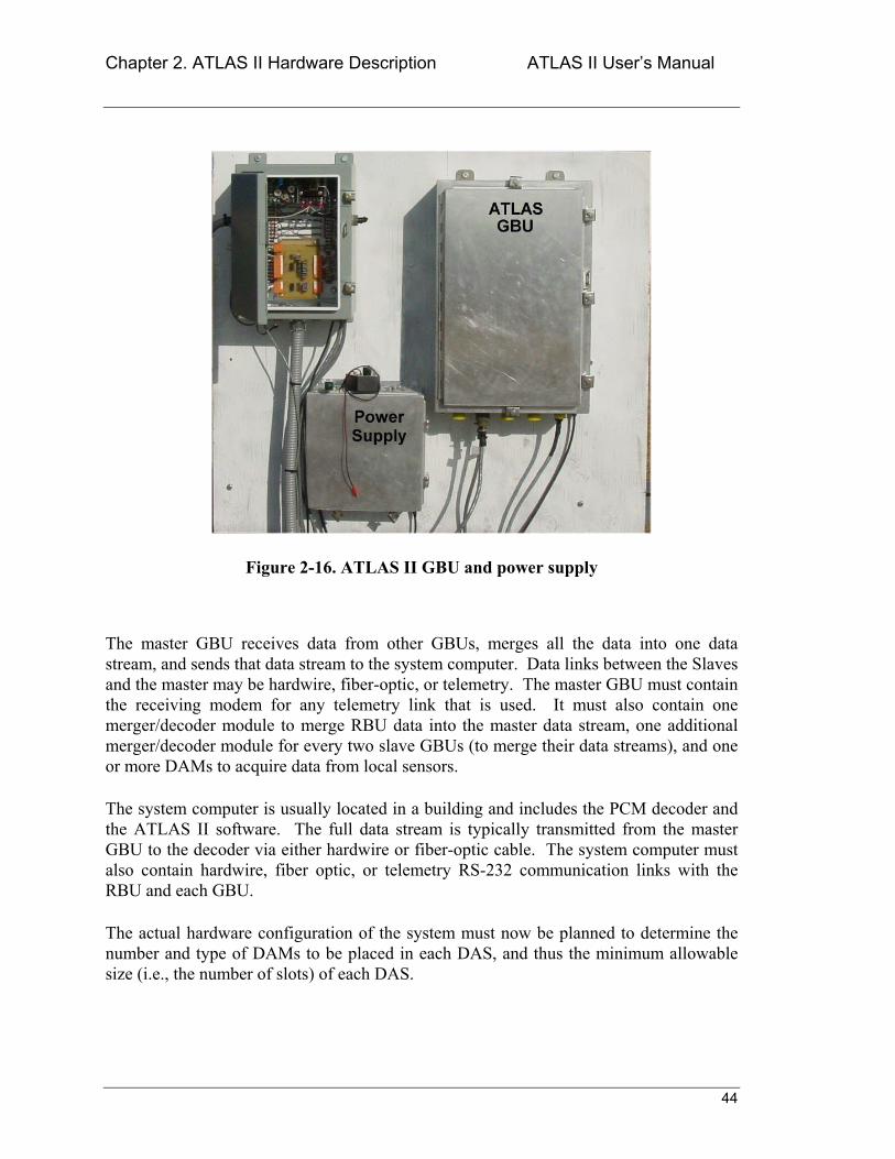
A GBU typically contains a DAS with associated DAMs and a PATSyM, a power sup-ply, lightning-protection equipment, and fiber-optic units if needed. All GBU units are now enclosed in an aluminum NEMA case, and all AC power has been eliminated from inside the unit. A separate power supply consisting of a 24 volt DC UPS with a backup battery capable of powering the system for 30 minutes, is shown in Figure 2-16.
Chapter 2. ATLAS II Hardware Description ATLAS II Users Manual
44
Figure 2-16. ATLAS II GBU and power supply
The master GBU receives data from other GBUs, merges all the data into one data stream, and sends that data stream to the system computer. Data links between the Slaves and the master may be hardwire, fiber-optic, or telemetry. The master GBU must contain the receiving modem for any telemetry link that is used. It must also contain one merger/decoder module to merge RBU data into the master data stream, one additional merger/decoder module for every two slave GBUs (to merge their data streams), and one or more DAMs to acquire data from local sensors.
The system computer is usually located in a building and includes the PCM decoder and the ATLAS II software. The full data stream is typically transmitted from the master GBU to the decoder via either hardwire or fiber-optic cable. The system computer must also contain hardwire, fiber optic, or telemetry RS-232 communication links with the RBU and each GBU.
The actual hardware configuration of the system must now be planned to determine the number and type of DAMs to be placed in each DAS, and thus the minimum allowable size (i.e., the number of slots) of each DAS.
Chapter 2. ATLAS II Hardware Description ATLAS II Users Manual
45
All DAS units should be located close to the sensors and indicators from which they are acquiring data in order to minimize contamination of the data by electrical noise picked up by analog signal wires.
The following steps will aid in identifying the components to be included in the RBU and the GBUs for a specific application.
1. Determine the number of data sensors to be monitored and the type of data to be acquired from each sensor.
a) Digital sensors will require the use of a digital input module (see Table 2-1 and Figure 2-5) with one line per bit connecting the sensor to the module and additional lines to provide sensor excitation, as needed. A digital input module will sample up to 48 bits of digital input.
b) Analog sensors (0 ± 10 V output) will require the use of a high-level analog input module (see Table 2-2 and Figure 2-6), with two lines connecting each signal to the module. A high-level analog module will sample up to eight differential analog inputs.
c) Strain-gauge sensors will require the use of a strain-gauge input module (see Table 2-3 and Figure 2-7). Strain gauges are normally connected to the instrumentation module with four wires per gauge (+ and excitation and + and signal). If the excitation wires between the module and the gauge are long enough that the voltage drop that will occur is of concern, run a 5th line (the B lead) between the two to permit sensing (and control) of the excitation voltage at the gauge itself. A strain-gauge module will handle as many as eight gauges. The normal strain-gauge modules will work with 120, 350, or 1000 Ω full-bridge configurations. Strain-gauge modules can also be factory configured to work with half-bridge or quarter-bridge strain gauge arrangements.
2. Determine the number of DAS units that will be used to acquire the data of interest. It is preferable to put a DAS close to each major group of sensors to minimize noise caused by long wires between the sensor and the associated DAS.
3. Determine the number of DAMs required in each DAS. As noted above, a single DAM will acquire up to eight channels of strain-gauge data, eight channels of high-level analog data, or 48 bits of digital data. Use this information to determine the minimum number of slots needed in each DAS. DAS units are available with 3, 6, 9, or 13 module slots.
NOTE
Chapter 2. ATLAS II Hardware Description ATLAS II Users Manual
46
4. The DAS that will be mounted on the rotor and used to acquire the rotor data becomes the RBU. All of the other DASs are called GBUs.
5. The RBU and each GBU will require a PATSyM to sychronize the acquisition timing (see Table 2-5 and Figure 2-12). It is possible to use a single PATSyM to synchronize two GBUs. However, the GBUs should be quite close to each other or the PATSyM clock pulse trains may degrade to the point where they will not properly trigger the DAS. It may be possible to drive three or more GBUs with a single PATSyM, but this has not yet been demonstrated.
6. Designate one GBU as the master. All GBUs, other than the master, will be considered slaves. As indicated above, the master unit receives the data streams from the slave GBUs and merges all of them into a single data stream for transmission to the system computer and storage to disk. One merger/decoder DAM will be required in the master to receive the data for every two slave GBU units. (see Table 2-4 and Figure 2-9).
7. Determine the number of lightning protection modules required for the RBU and each GBU.
8. Determine the number of power supplies required and the current requirements of each.
9. Determine the number and types of connectors needed.
10. Gather the necessary DAS units, DAMs, PATSyMs, the system computer, the power supplies, the lightning protection equipment, and the connectors. Although the usual procedure is to purchase everything required for an ATLAS II application, an agreement with SNL or National Renewable Energy Laboratory (NREL) may provide for the loan of DAS units and DAMs. In any case, the power supplies, lightning protection equipment, and connectors will probably have to be purchased. Be sure to purchase a few extra connectors to accommodate changes in instrumentation and communications.
Assembly of the ATLAS II for the specific application can now begin.
2.7.2 General Fabrication Notes
All lines into and out of the GBU or RBU should be shielded to minimize the possibility of introducing noise or induced voltages into those lines. The shield should be grounded either at the GBU/RBU or at the instrumentation end of the line, but not at both. Ground-ing at both ends creates a potential for a ground loop and could lead to inaccurate data. The power supply should also be shielded to keep the electrical noise generated by it from feeding noise into the data lines.

Chapter 2. ATLAS II Hardware Description ATLAS II Users Manual
47
All DAS units, including the RBU and the master GBU, should have encoder pin 6 wired to a +5 VDC or higher source whenever power is supplied to the DAS. This is necessary for the DAS to accept the clock information furnished to it by the PATSyM.
The necessary cables must be built to connect the compo-nents within each GBU and RBU and to connect those units to the instrumentation. See Appendices B and C for typical cable schematics.
For both GBUs and RBUs, the systems are wired so all serial data goes through the PAT-SyM. The user must switch the operating mode of the PATSyM to DAS in the ATLAS II GPS Data routine (see Section 3.2.4) before programming the RBU DAS. After the DAS is programmed, return to the ATLAS II GPS Data routine to switch the PATSyM mode back to GPS for normal operation. This is necessary to permit the user to both receive GPS serial data and program the DAS with only one RS-232 cable or modem pair.
2.7.3 Ground-Based Unit Assembly
As mentioned earlier, the GBUs are custom-built for each data acquisition installation, using the standard components described above. Examples of GBUs SNL has built may be found in Appendix C. The basic procedure to be followed is contained in the follow-ing paragraphs.
The components for each GBU must be mounted in an enclosure suitable for the envi-ronment in which that GBU will be located. Keep in mind that the DAS units generate heat when operating, and that heat must be dissipated. Since the size and weight of the GBU are not usually serious issues, consider utilizing metal weatherproof boxes for all external GBUs, and mount the DAS units directly to the metal floor of the boxes. For indoor applications, mount the DAS units on metal shelves in instrumentation racks.
Additional information on KAM-500 instrumentation module operation and wiring may be found in the manuals supplied by ACRA Control with those units.
2.7.4 Rotor-Based Unit Assembly
The RBUs are also custom-built for each particular application. In general, they are built very much like the GBUs, but with the added requirements of small size and lightweight. The requirement to reduce weight has led SNL to use a waterproof SerPac R-Series case8 for the container. These cases are made of lightweight structural resin, are stout enough to provide a solid base for the RBU components, and withstand the weather and sunlight well. They include an integral handle, which makes them easy to transport and maneu- 8 Serpac Cases, 619 Commercial Ave., Covina, CA 91723
NOTE
Chapter 2. ATLAS II Hardware Description ATLAS II Users Manual
48
ver. However, the cases must be modified by cutting out the bottom of the case and in-serting a metal mounting plate. The joint between the plate and the case must be care-fully sealed to insure that the modified case weatherproof. The plate serves as a solid mounting for the DAS and other components of the RBU, provides a means of mounting the RBU to the rotor hub, and provides a good heat conduction path from the DAS into the rotor hub.
As mentioned earlier, two Digital Wireless WIT-2400 modems are used for RBU radio communications, one to handle the user-interface communications with the GPS and the DAS, and the other to transfer the PCM data stream from the DAS to the ground receiv-ing station. The RBU assembly uses only the actual modem module shown in the lower right-hand section of Figure 2-15, without the RS-232 interface, indicator lights, and power supply that are found in a modem enclosure, as shown in the upper right-hand sec-tion of Figure 2-15. The CMOS-level signals of the PATSyM (pins 48 and 49) directly to the radio module (receive and transmit, respectively) to minimize space requirements, and to keep complexity and power consumption to a minimum. The radio modems are mounted either on the DAS unit or very close to it.
Schematics of RBUs SNL has built are included in Appendix C and photos of those units are included in Appendix F.
The receiving data modem, normally located near the master GBU, must be modified to bring the RX_CLK, the RX_DATA, and GND lines out directly from the radio module into the appropriate merger/decoder module. The ground-based RS-232 modem, on the other hand, requires no modification it is simply attached to the system computer serial port via a standard 9-pin serial cable. The two RBU modems and the two receiving mo-dems must be programmed before the RBU is assembled. Details of the programming may be found in Appendix G.
Failure to switch the PATSyM operating mode to DAS prior to attempting to program the RBU will cause the pro-gram routine to fail it will hang up attempting to pro-gram the RBU. If programming takes over 10 minutes, press the Cancel button and wait for the routine to ter-minate.
NOTE
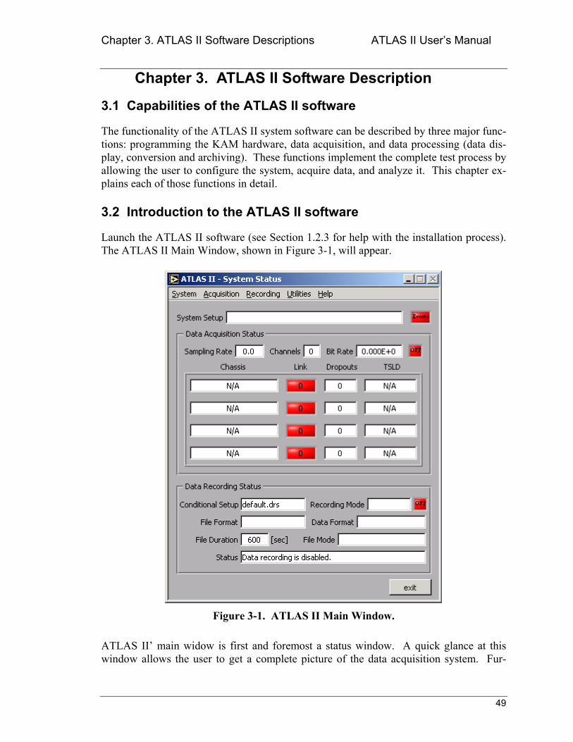
Chapter 3. ATLAS II Software Descriptions ATLAS II Users Manual
49
Chapter 3. ATLAS II Software Description
3.1 Capabilities of the ATLAS II software
The functionality of the ATLAS II system software can be described by three major func-tions: programming the KAM hardware, data acquisition, and data processing (data dis-play, conversion and archiving). These functions implement the complete test process by allowing the user to configure the system, acquire data, and analyze it. This chapter ex-plains each of those functions in detail.
3.2 Introduction to the ATLAS II software
Launch the ATLAS II software (see Section 1.2.3 for help with the installation process). The ATLAS II Main Window, shown in Figure 3-1, will appear.
Figure 3-1. ATLAS II Main Window.
ATLAS II main widow is first and foremost a status window. A quick glance at this window allows the user to get a complete picture of the data acquisition system. Fur-
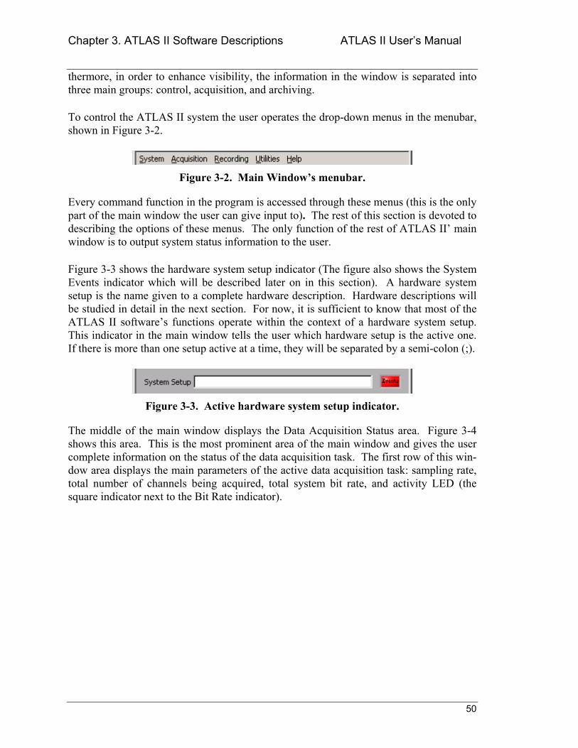
Chapter 3. ATLAS II Software Descriptions ATLAS II Users Manual
50
thermore, in order to enhance visibility, the information in the window is separated into three main groups: control, acquisition, and archiving.
To control the ATLAS II system the user operates the drop-down menus in the menubar, shown in Figure 3-2.
Figure 3-2. Main Windows menubar.
Every command function in the program is accessed through these menus (this is the only part of the main window the user can give input to). The rest of this section is devoted to describing the options of these menus. The only function of the rest of ATLAS II main window is to output system status information to the user.
Figure 3-3 shows the hardware system setup indicator (The figure also shows the System Events indicator which will be described later on in this section). A hardware system setup is the name given to a complete hardware description. Hardware descriptions will be studied in detail in the next section. For now, it is sufficient to know that most of the ATLAS II softwares functions operate within the context of a hardware system setup. This indicator in the main window tells the user which hardware setup is the active one. If there is more than one setup active at a time, they will be separated by a semi-colon (;).
Figure 3-3. Active hardware system setup indicator.
The middle of the main window displays the Data Acquisition Status area. Figure 3-4 shows this area. This is the most prominent area of the main window and gives the user complete information on the status of the data acquisition task. The first row of this win-dow area displays the main parameters of the active data acquisition task: sampling rate, total number of channels being acquired, total system bit rate, and activity LED (the square indicator next to the Bit Rate indicator).
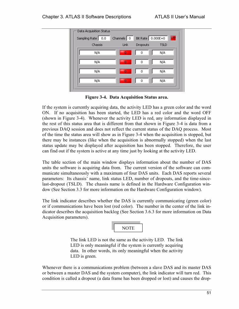
Chapter 3. ATLAS II Software Descriptions ATLAS II Users Manual
51
Figure 3-4. Data Acquisition Status area.
If the system is currently acquiring data, the activity LED has a green color and the word ON. If no acquisition has been started, the LED has a red color and the word OFF (shown in Figure 3-4). Whenever the activity LED is red, any information displayed in the rest of this status area that is different from that shown in Figure 3-4 is data from a previous DAQ session and does not reflect the current status of the DAQ process. Most of the time the status area will show as in Figure 3-4 when the acquisition is stopped, but there may be instances (like when the acquisition is abnormally stopped) when the last status update may be displayed after acquisition has been stopped. Therefore, the user can find out if the system is active at any time just by looking at the activity LED.
The table section of the main window displays information about the number of DAS units the software is acquiring data from. The current version of the software can com-municate simultaneously with a maximum of four DAS units. Each DAS reports several parameters: Its chassis name, link status LED, number of dropouts, and the time-since-last-dropout (TSLD). The chassis name is defined in the Hardware Configuration win-dow (See Section 3.3 for more information on the Hardware Configuration window).
The link indicator describes whether the DAS is currently communicating (green color) or if communications have been lost (red color). The number in the center of the link in-dicator describes the acquisition backlog (See Section 3.6.3 for more information on Data Acquisition parameters).
The link LED is not the same as the activity LED. The link LED is only meaningful if the system is currently acquiring data. In other words, its only meaningful when the activity LED is green.
Whenever there is a communications problem (between a slave DAS and its master DAS or between a master DAS and the system computer), the link indicator will turn red. This condition is called a dropout (a data frame has been dropped or lost) and causes the drop-
NOTE
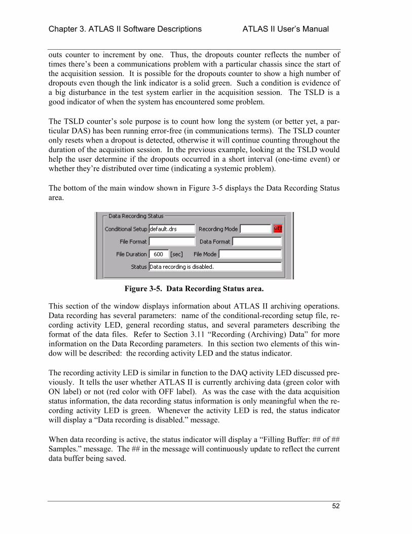
Chapter 3. ATLAS II Software Descriptions ATLAS II Users Manual
52
outs counter to increment by one. Thus, the dropouts counter reflects the number of times theres been a communications problem with a particular chassis since the start of the acquisition session. It is possible for the dropouts counter to show a high number of dropouts even though the link indicator is a solid green. Such a condition is evidence of a big disturbance in the test system earlier in the acquisition session. The TSLD is a good indicator of when the system has encountered some problem.
The TSLD counters sole purpose is to count how long the system (or better yet, a par-ticular DAS) has been running error-free (in communications terms). The TSLD counter only resets when a dropout is detected, otherwise it will continue counting throughout the duration of the acquisition session. In the previous example, looking at the TSLD would help the user determine if the dropouts occurred in a short interval (one-time event) or whether theyre distributed over time (indicating a systemic problem).
The bottom of the main window shown in Figure 3-5 displays the Data Recording Status area.
Figure 3-5. Data Recording Status area.
This section of the window displays information about ATLAS II archiving operations. Data recording has several parameters: name of the conditional-recording setup file, re-cording activity LED, general recording status, and several parameters describing the format of the data files. Refer to Section 3.11 Recording (Archiving) Data for more information on the Data Recording parameters. In this section two elements of this win-dow will be described: the recording activity LED and the status indicator.
The recording activity LED is similar in function to the DAQ activity LED discussed pre-viously. It tells the user whether ATLAS II is currently archiving data (green color with ON label) or not (red color with OFF label). As was the case with the data acquisition status information, the data recording status information is only meaningful when the re-cording activity LED is green. Whenever the activity LED is red, the status indicator will display a Data recording is disabled. message.
When data recording is active, the status indicator will display a Filling Buffer: ## of ## Samples. message. The ## in the message will continuously update to reflect the current data buffer being saved.
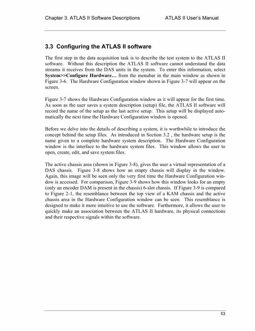
Chapter 3. ATLAS II Software Descriptions ATLAS II Users Manual
53
3.3 Configuring the ATLAS II software
The first step in the data acquisition task is to describe the test system to the ATLAS II software. Without this description the ATLAS II software cannot understand the data streams it receives from the DAS units in the system. To enter this information, select System>>Configure Hardware from the menubar in the main window as shown in Figure 3-6. The Hardware Configuration window shown in Figure 3-7 will appear on the screen.
Figure 3-7 shows the Hardware Configuration window as it will appear for the first time. As soon as the user saves a system description (setup) file, the ATLAS II software will record the name of the setup as the last active setup. This setup will be displayed auto-matically the next time the Hardware Configuration window is opened.
Before we delve into the details of describing a system, it is worthwhile to introduce the concept behind the setup files. As introduced in Section 3.2 , the hardware setup is the name given to a complete hardware system description. The Hardware Configuration window is the interface to the hardware system files. This window allows the user to open, create, edit, and save system files.
The active chassis area (shown in Figure 3-8), gives the user a virtual representation of a DAS chassis. Figure 3-8 shows how an empty chassis will display in the window. Again, this image will be seen only the very first time the Hardware Configuration win-dow is accessed. For comparison, Figure 3-9 shows how this window looks for an empty (only an encoder DAM is present in the chassis) 6-slot chassis. If Figure 3-9 is compared to Figure 2-1, the resemblance between the top view of a KAM chassis and the active chassis area in the Hardware Configuration window can be seen. This resemblance is designed to make it more intuitive to use the software. Furthermore, it allows the user to quickly make an association between the ATLAS II hardware, its physical connections and their respective signals within the software.
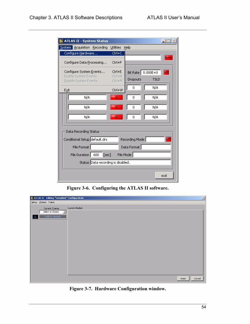
Chapter 3. ATLAS II Software Descriptions ATLAS II Users Manual
54
Figure 3-6. Configuring the ATLAS II software.
Figure 3-7. Hardware Configuration window.
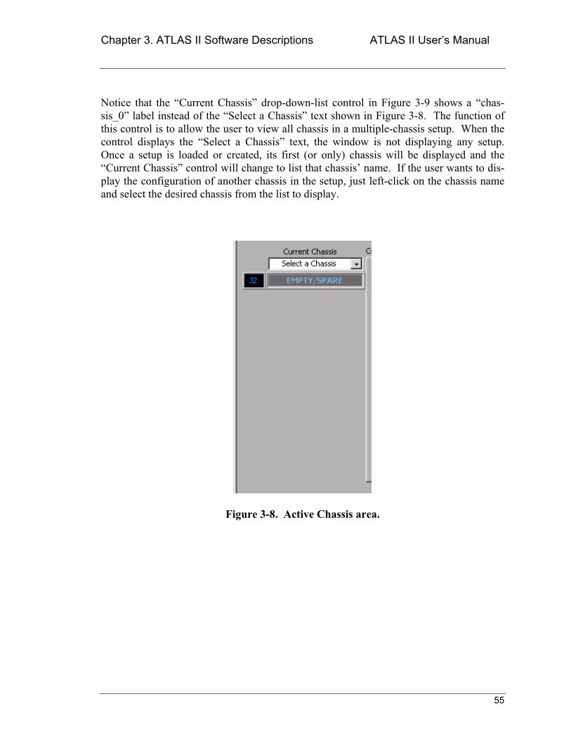
Chapter 3. ATLAS II Software Descriptions ATLAS II Users Manual
55
Notice that the Current Chassis drop-down-list control in Figure 3-9 shows a chas-sis_0 label instead of the Select a Chassis text shown in Figure 3-8. The function of this control is to allow the user to view all chassis in a multiple-chassis setup. When the control displays the Select a Chassis text, the window is not displaying any setup. Once a setup is loaded or created, its first (or only) chassis will be displayed and the Current Chassis control will change to list that chassis name. If the user wants to dis-play the configuration of another chassis in the setup, just left-click on the chassis name and select the desired chassis from the list to display.
Figure 3-8. Active Chassis area.
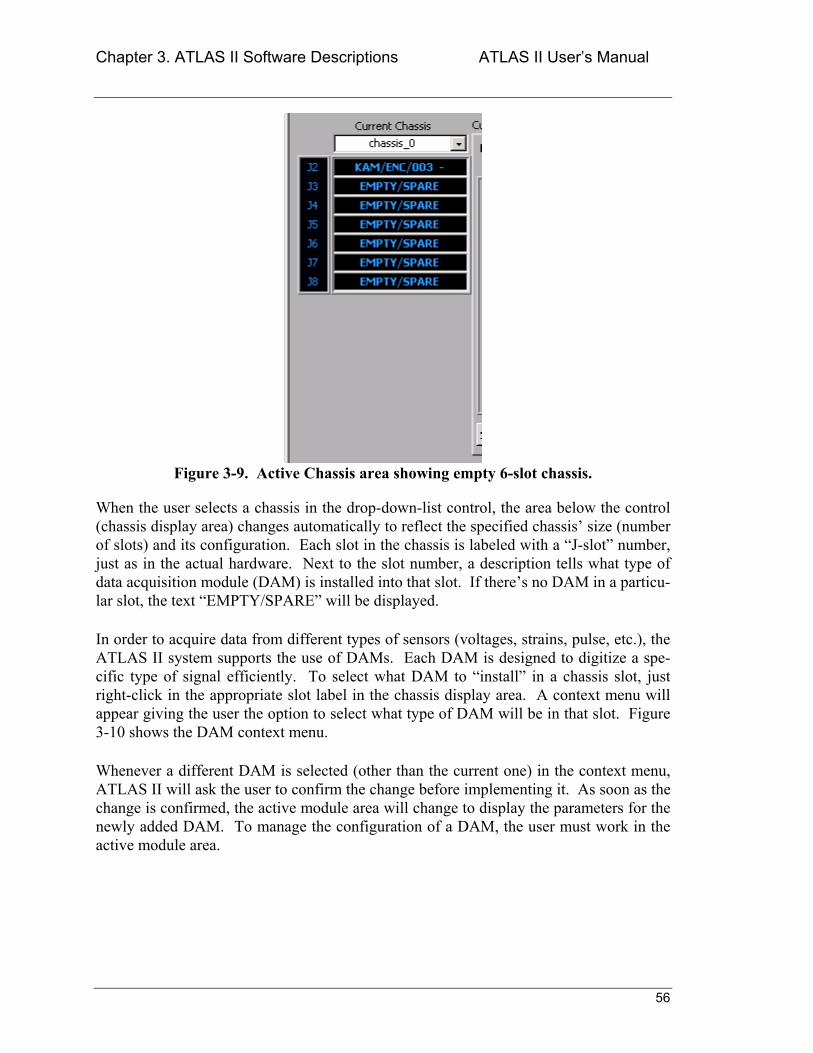
Chapter 3. ATLAS II Software Descriptions ATLAS II Users Manual
56
Figure 3-9. Active Chassis area showing empty 6-slot chassis.
When the user selects a chassis in the drop-down-list control, the area below the control (chassis display area) changes automatically to reflect the specified chassis size (number of slots) and its configuration. Each slot in the chassis is labeled with a J-slot number, just as in the actual hardware. Next to the slot number, a description tells what type of data acquisition module (DAM) is installed into that slot. If theres no DAM in a particu-lar slot, the text EMPTY/SPARE will be displayed.
In order to acquire data from different types of sensors (voltages, strains, pulse, etc.), the ATLAS II system supports the use of DAMs. Each DAM is designed to digitize a spe-cific type of signal efficiently. To select what DAM to install in a chassis slot, just right-click in the appropriate slot label in the chassis display area. A context menu will appear giving the user the option to select what type of DAM will be in that slot. Figure 3-10 shows the DAM context menu.
Whenever a different DAM is selected (other than the current one) in the context menu, ATLAS II will ask the user to confirm the change before implementing it. As soon as the change is confirmed, the active module area will change to display the parameters for the newly added DAM. To manage the configuration of a DAM, the user must work in the active module area.
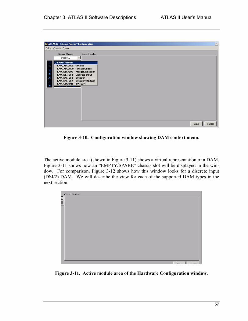
Chapter 3. ATLAS II Software Descriptions ATLAS II Users Manual
57
Figure 3-10. Configuration window showing DAM context menu.
The active module area (shown in Figure 3-11) shows a virtual representation of a DAM. Figure 3-11 shows how an EMPTY/SPARE chassis slot will be displayed in the win-dow. For comparison, Figure 3-12 shows how this window looks for a discrete input (DSI/2) DAM. We will describe the view for each of the supported DAM types in the next section.
Figure 3-11. Active module area of the Hardware Configuration window.
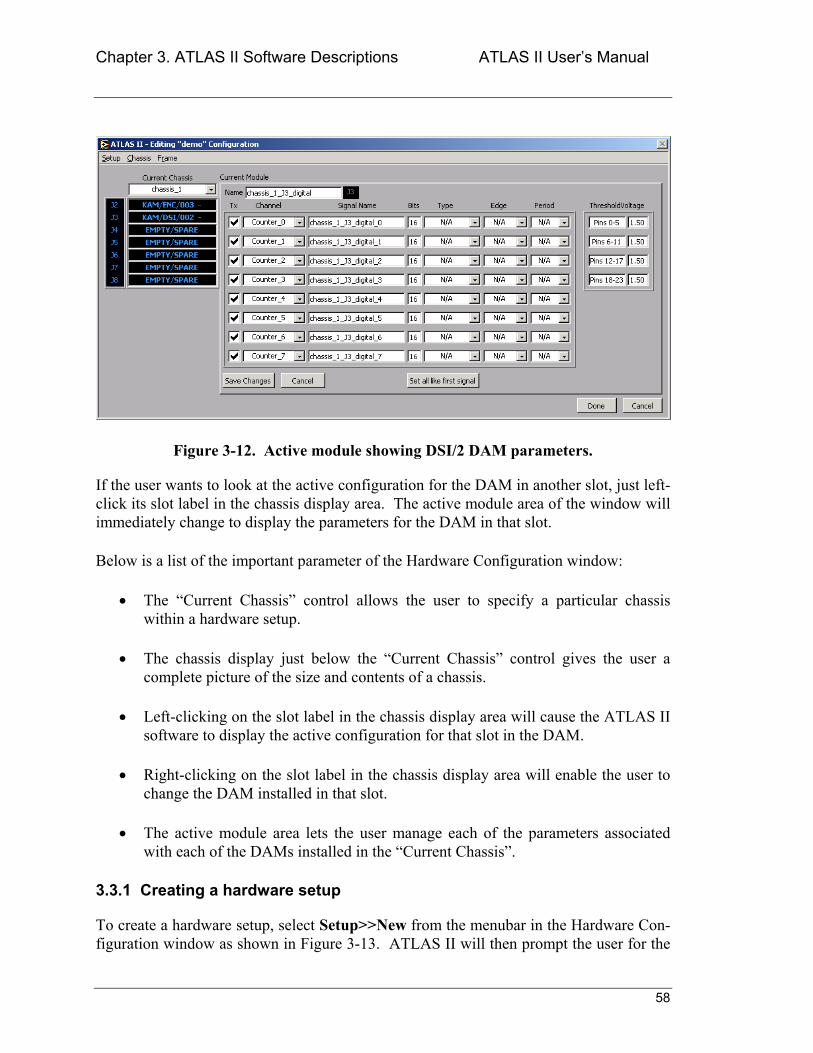
Chapter 3. ATLAS II Software Descriptions ATLAS II Users Manual
58
Figure 3-12. Active module showing DSI/2 DAM parameters.
If the user wants to look at the active configuration for the DAM in another slot, just left-click its slot label in the chassis display area. The active module area of the window will immediately change to display the parameters for the DAM in that slot.
Below is a list of the important parameter of the Hardware Configuration window:
• The Current Chassis control allows the user to specify a particular chassis within a hardware setup.
• The chassis display just below the Current Chassis control gives the user a complete picture of the size and contents of a chassis.
• Left-clicking on the slot label in the chassis display area will cause the ATLAS II software to display the active configuration for that slot in the DAM.
• Right-clicking on the slot label in the chassis display area will enable the user to change the DAM installed in that slot.
• The active module area lets the user manage each of the parameters associated with each of the DAMs installed in the Current Chassis.
3.3.1 Creating a hardware setup
To create a hardware setup, select Setup>>New from the menubar in the Hardware Con-figuration window as shown in Figure 3-13. ATLAS II will then prompt the user for the
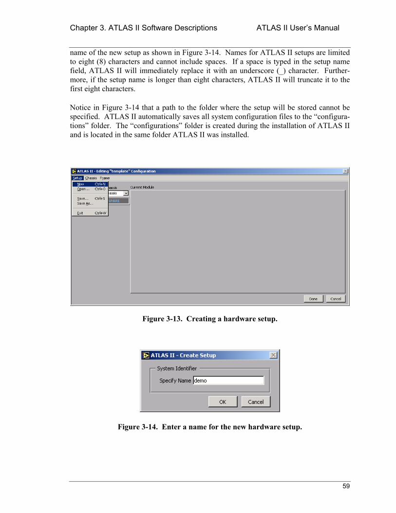
Chapter 3. ATLAS II Software Descriptions ATLAS II Users Manual
59
name of the new setup as shown in Figure 3-14. Names for ATLAS II setups are limited to eight (8) characters and cannot include spaces. If a space is typed in the setup name field, ATLAS II will immediately replace it with an underscore (_) character. Further-more, if the setup name is longer than eight characters, ATLAS II will truncate it to the first eight characters.
Notice in Figure 3-14 that a path to the folder where the setup will be stored cannot be specified. ATLAS II automatically saves all system configuration files to the configura-tions folder. The configurations folder is created during the installation of ATLAS II and is located in the same folder ATLAS II was installed.
Figure 3-13. Creating a hardware setup.
Figure 3-14. Enter a name for the new hardware setup.
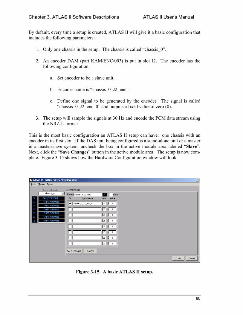
Chapter 3. ATLAS II Software Descriptions ATLAS II Users Manual
60
By default, every time a setup is created, ATLAS II will give it a basic configuration that includes the following parameters:
1. Only one chassis in the setup. The chassis is called chassis_0.
2. An encoder DAM (part KAM/ENC/003) is put in slot J2. The encoder has the following configuration:
a. Set encoder to be a slave unit.
b. Encoder name is chassis_0_J2_enc.
c. Define one signal to be generated by the encoder. The signal is called chassis_0_J2_enc_0 and outputs a fixed value of zero (0).
3. The setup will sample the signals at 30 Hz and encode the PCM data stream using the NRZ-L format.
This is the most basic configuration an ATLAS II setup can have: one chassis with an encoder in its first slot. If the DAS unit being configured is a stand-alone unit or a master in a master/slave system, uncheck the box in the active module area labeled Slave. Next, click the Save Changes button in the active module area. The setup is now com-plete. Figure 3-15 shows how the Hardware Configuration window will look.
Figure 3-15. A basic ATLAS II setup.
Chapter 3. ATLAS II Software Descriptions ATLAS II Users Manual
61
Notice that the text in the title bar of the Hardware Configuration window changes to dis-play the name of the setup being edited, in this case demo.
Now that a basic setup has been created, the next sections will describe all the configura-tion parameters available with the different DAMs supported by ATLAS II. This will let the user create ATLAS II systems with high degrees of sophistication.
Chapter 3. ATLAS II Software Descriptions ATLAS II Users Manual
62
3.3.2 Configuring ATLAS II DAMs
As of this release ATLAS II includes support for the following data acquisition modules (DAMs):
1. KAM/ENC/003: encoder/controller module with RS-422 programming interface.
2. KAM/ENC/007: encoder/ controller module with RS-232 programming inter-face.
3. KAM/DEC/002: 2-channel merger/decoder module.
4. KAM/ADC/005: 8-channel differential analog to digital converter with signal conditioning.
5. KAM/ADC/009/S2: 8-channel bridge analog to digital converter with excitation, sense and signal conditioning.
6. KAM/DSI/002: 24-channel discrete input module with counters.
7. GPS/001: GPS receiver/timing reference module.
The rest of this section describes each module in detail. In the discussion, every time that a name is specified (for example for a Module Name or a Signal Name), ATLAS II will allow the user to enter up to 25 characters. The limit is not specific because the maxi-mum number of characters that can be displayed will depend on system settings such as the type and attributes of the active system font.
3.3.2.1 KAM/ENC/003 - Encoder module parameters
The KAM/ENC/003 is the brains of every DAS unit. Its job is to build the PCM data stream using the just-acquired samples from all of the DAMs in a DAS chassis. Data cannot be acquired from a DAS unit and none of the installed DAMs can be programmed if a KAM/ENC/003 is not installed in the DAS unit. KAM/ENC/003 DAMs can only be installed in a chassis on the J2 slot. Furthermore, no other DAM (other than encoder DAMs) can be installed in the chassis J2 slot.
Figure 3-16 shows the active module area of the Hardware Configuration window when configuring a KAM/ENC/003 module. The parameters available for configuration in this window are:
• Name Name used by ATLAS II to identify this module as a signal source. The user can specify any name. Do not use spaces in the name (if spaces are used, ATLAS II will replace them with underscore (_) characters).
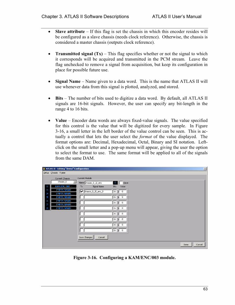
Chapter 3. ATLAS II Software Descriptions ATLAS II Users Manual
63
• Slave attribute If this flag is set the chassis in which this encoder resides will be configured as a slave chassis (needs clock reference). Otherwise, the chassis is considered a master chassis (outputs clock reference).
• Transmitted signal (Tx) This flag specifies whether or not the signal to which it corresponds will be acquired and transmitted in the PCM stream. Leave the flag unchecked to remove a signal from acquisition, but keep its configuration in place for possible future use.
• Signal Name Name given to a data word. This is the name that ATLAS II will use whenever data from this signal is plotted, analyzed, and stored.
• Bits The number of bits used to digitize a data word. By default, all ATLAS II signals are 16-bit signals. However, the user can specify any bit-length in the range 4 to 16 bits.
• Value Encoder data words are always fixed-value signals. The value specified for this control is the value that will be digitized for every sample. In Figure 3-16, a small letter in the left border of the value control can be seen. This is ac-tually a control that lets the user select the format of the value displayed. The format options are: Decimal, Hexadecimal, Octal, Binary and SI notation. Left-click on the small letter and a pop-up menu will appear, giving the user the option to select the format to use. The same format will be applied to all of the signals from the same DAM.
Figure 3-16. Configuring a KAM/ENC/003 module.
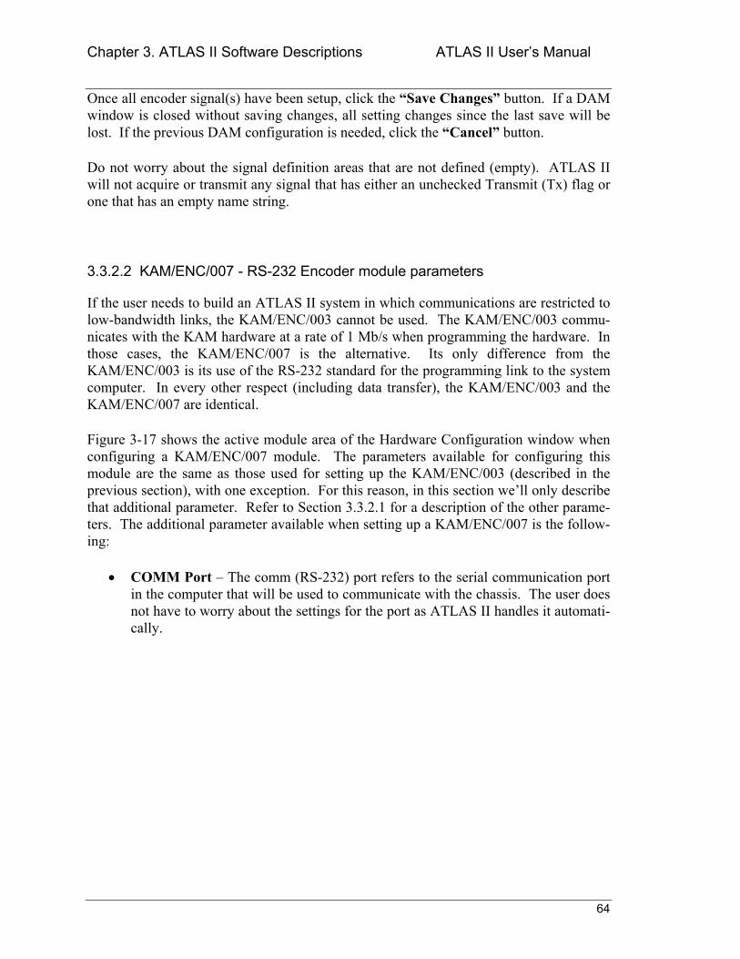
Chapter 3. ATLAS II Software Descriptions ATLAS II Users Manual
64
Once all encoder signal(s) have been setup, click the Save Changes button. If a DAM window is closed without saving changes, all setting changes since the last save will be lost. If the previous DAM configuration is needed, click the Cancel button.
Do not worry about the signal definition areas that are not defined (empty). ATLAS II will not acquire or transmit any signal that has either an unchecked Transmit (Tx) flag or one that has an empty name string.
3.3.2.2 KAM/ENC/007 - RS-232 Encoder module parameters
If the user needs to build an ATLAS II system in which communications are restricted to low-bandwidth links, the KAM/ENC/003 cannot be used. The KAM/ENC/003 commu-nicates with the KAM hardware at a rate of 1 Mb/s when programming the hardware. In those cases, the KAM/ENC/007 is the alternative. Its only difference from the KAM/ENC/003 is its use of the RS-232 standard for the programming link to the system computer. In every other respect (including data transfer), the KAM/ENC/003 and the KAM/ENC/007 are identical.
Figure 3-17 shows the active module area of the Hardware Configuration window when configuring a KAM/ENC/007 module. The parameters available for configuring this module are the same as those used for setting up the KAM/ENC/003 (described in the previous section), with one exception. For this reason, in this section well only describe that additional parameter. Refer to Section 3.3.2.1 for a description of the other parame-ters. The additional parameter available when setting up a KAM/ENC/007 is the follow-ing:
• COMM Port The comm (RS-232) port refers to the serial communication port in the computer that will be used to communicate with the chassis. The user does not have to worry about the settings for the port as ATLAS II handles it automati-cally.
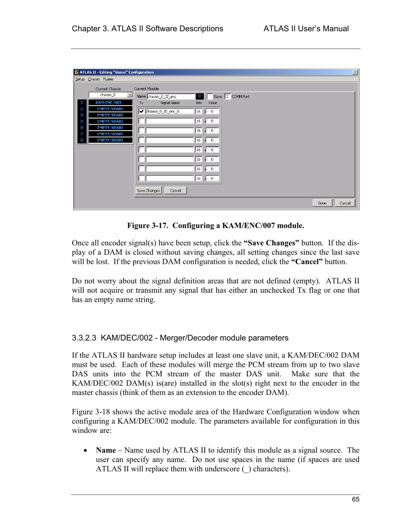
Chapter 3. ATLAS II Software Descriptions ATLAS II Users Manual
65
Figure 3-17. Configuring a KAM/ENC/007 module.
Once all encoder signal(s) have been setup, click the Save Changes button. If the dis-play of a DAM is closed without saving changes, all setting changes since the last save will be lost. If the previous DAM configuration is needed, click the Cancel button.
Do not worry about the signal definition areas that are not defined (empty). ATLAS II will not acquire or transmit any signal that has either an unchecked Tx flag or one that has an empty name string.
3.3.2.3 KAM/DEC/002 - Merger/Decoder module parameters
If the ATLAS II hardware setup includes at least one slave unit, a KAM/DEC/002 DAM must be used. Each of these modules will merge the PCM stream from up to two slave DAS units into the PCM stream of the master DAS unit. Make sure that the KAM/DEC/002 DAM(s) is(are) installed in the slot(s) right next to the encoder in the master chassis (think of them as an extension to the encoder DAM).
Figure 3-18 shows the active module area of the Hardware Configuration window when configuring a KAM/DEC/002 module. The parameters available for configuration in this window are:
• Name Name used by ATLAS II to identify this module as a signal source. The user can specify any name. Do not use spaces in the name (if spaces are used ATLAS II will replace them with underscore (_) characters).
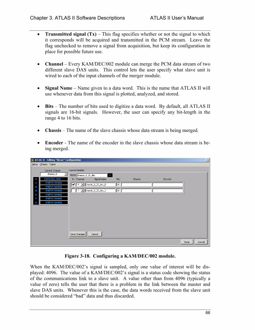
Chapter 3. ATLAS II Software Descriptions ATLAS II Users Manual
66
• Transmitted signal (Tx) This flag specifies whether or not the signal to which it corresponds will be acquired and transmitted in the PCM stream. Leave the flag unchecked to remove a signal from acquisition, but keep its configuration in place for possible future use.
• Channel Every KAM/DEC/002 module can merge the PCM data stream of two different slave DAS units. This control lets the user specify what slave unit is wired to each of the input channels of the merger module.
• Signal Name Name given to a data word. This is the name that ATLAS II will use whenever data from this signal is plotted, analyzed, and stored.
• Bits The number of bits used to digitize a data word. By default, all ATLAS II signals are 16-bit signals. However, the user can specify any bit-length in the range 4 to 16 bits.
• Chassis The name of the slave chassis whose data stream is being merged.
• Encoder - The name of the encoder in the slave chassis whose data stream is be-ing merged.
Figure 3-18. Configuring a KAM/DEC/002 module.
When the KAM/DEC/002s signal is sampled, only one value of interest will be dis-played: 4096. The value of a KAM/DEC/002s signal is a status code showing the status of the communications link to a slave unit. A value other than from 4096 (typically a value of zero) tells the user that there is a problem in the link between the master and slave DAS units. Whenever this is the case, the data words received from the slave unit should be considered bad data and thus discarded.
Chapter 3. ATLAS II Software Descriptions ATLAS II Users Manual
67
Once the merger/decoder signal(s) have been setup, click the Save Changes button. If the DAM display is closed without saving changes, all setting changes since the last save will be lost. If the previous DAM configuration is needed, click the Cancel button.
Do not worry about the signal definition areas that are not defined (empty). ATLAS II will not acquire or transmit any signal that has either an unchecked Tx flag or one that has an empty name string.
3.3.2.4 KAM/ADC/005 - Analog input module parameters
The KAM/ADC/005 is the most widely used DAM in a typical ATLAS II system. It is a generic analog-to-digital converter module with integrated signal conditioning. Its versa-tility is due for the most part to its amplification and filtering capabilities. The KAM/ADC/005 can capture signals with amplitudes from millivolts to 10 Volts. More-over, it uses digital filters to produce highly accurate, non-distorted samples.
Figure 3-19. Configuring a KAM/ADC/005 module.
Figure 3-19 shows the active module area of the Hardware Configuration window when configuring a KAM/ADC/005 module. The parameters available for configuration in this window are:
• Name Name used by ATLAS II to identify this module as a signal source. The user can specify any name (up to 25 characters). Do not use spaces in the name (if spaces are used, ATLAS II will replace them with underscore (_) characters).
Chapter 3. ATLAS II Software Descriptions ATLAS II Users Manual
68
• Transmitted signal (Tx) This flag specifies whether or not the signal to which it corresponds will be acquired and transmitted in the PCM stream. Leave the flag unchecked to remove a signal from acquisition, but keep its configuration in place for possible future use.
• Channel Each KAM/ADC/005 can sample up to eight (8) different signals. This control lets the user specify which physical channel in the DAM is receiving a given signal.
• Signal Name Name given to a data word. This is the name that ATLAS II will use whenever data from this signal is plotted, analyzed, and stored.
• Bits The number of bits used to digitize a data word. By default, all ATLAS II signals are 16-bit signals. However, the user can specify any bit-length in the range 4 to 16 bits.
• Max This control specifies the maximum input value (in Volts) that will be pre-sent at the KAM/ADC/005s input terminals for a given signal. The maximum acceptable value is 10.0V. If the user specifies anything larger than 10V, ATLAS II will limit the input to 10V.
• Min This control specifies the minimum input value (in Volts) that will be pre-sent at the KAM/ADC/005s input terminals for a given signal. The minimum acceptable value is 9.995V. If the user specifies anything smaller than 9.995V, ATLAS II will limit the input to 9.995V.
• Filter Cutoff Drop-down control that lets the user specify the 3dB point of a given signals digital filter. The frequency is expressed as a multiple of the sam-pling frequency (Fs). This setting will also determine the magnitude of the time delay associated with the filtering operation. That delay is governed by the fol-lowing relationship:
Td = 13/Fc, where Fc is the filter cutoff frequency.
For example, if a filter cutoff frequency of Fs/4 is specified for a signal thats been sampled at 30 Hz, expect a time delay of approximately 1.73 seconds.
To simplify setting up a KAM/ADC/005 DAM, ATLAS II includes the Set all like first signal button. As its name implies, clicking this button will set all of the parameters for all of the active DAMs signals to those set for the first signal. The signal name parame-ter will also be copied, but a _# (where # will be replaced by the signals channel num-ber) will be appended to every name thats created.
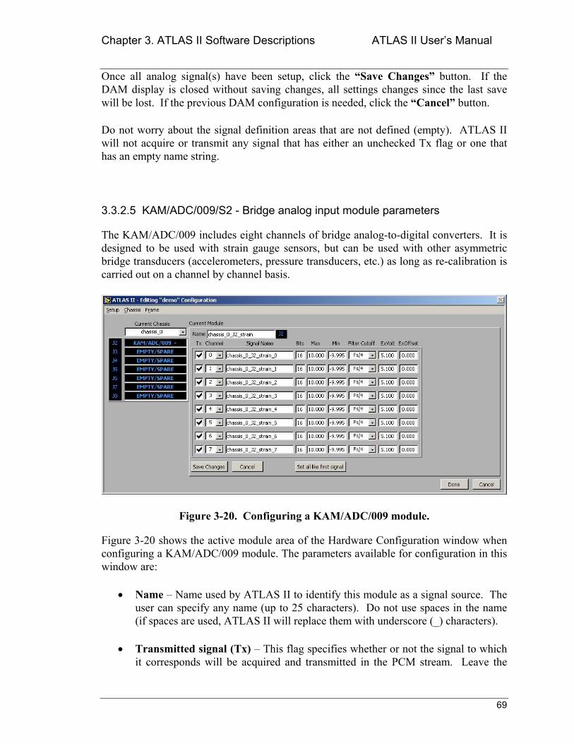
Chapter 3. ATLAS II Software Descriptions ATLAS II Users Manual
69
Once all analog signal(s) have been setup, click the Save Changes button. If the DAM display is closed without saving changes, all settings changes since the last save will be lost. If the previous DAM configuration is needed, click the Cancel button.
Do not worry about the signal definition areas that are not defined (empty). ATLAS II will not acquire or transmit any signal that has either an unchecked Tx flag or one that has an empty name string.
3.3.2.5 KAM/ADC/009/S2 - Bridge analog input module parameters
The KAM/ADC/009 includes eight channels of bridge analog-to-digital converters. It is designed to be used with strain gauge sensors, but can be used with other asymmetric bridge transducers (accelerometers, pressure transducers, etc.) as long as re-calibration is carried out on a channel by channel basis.
Figure 3-20. Configuring a KAM/ADC/009 module.
Figure 3-20 shows the active module area of the Hardware Configuration window when configuring a KAM/ADC/009 module. The parameters available for configuration in this window are:
• Name Name used by ATLAS II to identify this module as a signal source. The user can specify any name (up to 25 characters). Do not use spaces in the name (if spaces are used, ATLAS II will replace them with underscore (_) characters).
• Transmitted signal (Tx) This flag specifies whether or not the signal to which it corresponds will be acquired and transmitted in the PCM stream. Leave the
Chapter 3. ATLAS II Software Descriptions ATLAS II Users Manual
70
flag unchecked to remove a signal from acquisition, but keep its configuration in place for possible future use.
• Channel Each KAM/ADC/009 can sample up to eight (8) different signals. This control lets the user specify which physical channel in the DAM is receiving a given signal.
• Signal Name Name given to a data word. This is the name that ATLAS II will use whenever data from this signal is plotted, analyzed, and stored.
• Bits The number of bits used to digitize a data word. By default, all ATLAS II signals are 16-bit signals. However, the user can specify any bit-length in the range 4 to 16 bits.
• Max This control specifies the maximum input value (in Volts) that will be pre-sent at the KAM/ADC/009s input terminals for a given signal. The maximum acceptable value is 10.0V. If a value larger than 10V is specified, ATLAS II will limit the input to 10V. For sampling strain gauge transducers, a setting of 0.010 V will typically provide the best dynamic range and resolution.
• Min This control specifies the minimum input value (in Volts) that will be pre-sent at the KAM/ADC/009s input terminals for a given signal. The minimum acceptable value is 9.995V. If a value smaller than 9.995V is specified, ATLAS II will limit the input to 9.995V.
• Filter Cutoff Drop-down control that lets the user specify the 3dB point of a given signals digital filter. The frequency is expressed as a multiple of the sam-pling frequency (Fs). This setting will also determine the magnitude of the time delay associated with the filtering operation. That delay is governed by the fol-lowing relationship:
Td = 13/Fc, where Fc is the filter cutoff frequency.
For example, if a filter cutoff of Fs/4 is selected for a signal thats been sampled at 30 Hz, a time delay of approximately 1.73 seconds can be expected.
• ExVolt Specifies the voltage across half-bridge. A value of 2.5V will result in a voltage of 5V being present across the bridge. This parameter has a range of 5.1V to 0.0V. If a value outside that range is specified, ATLAS II will limit the input to force it within range.
• ExOffset Specifies a voltage to be added to the excitation voltage (ExVolt) to balance a given signals bridge. This parameter has a range of 2.5V to 2.5V. If a value outside that range is specified, ATLAS II will limit the input to force it within range.
Chapter 3. ATLAS II Software Descriptions ATLAS II Users Manual
71
To simplify setting up a KAM/ADC/009 DAM, ATLAS II includes the Set all like first signal button. As its name implies, clicking this button will set all of the parameters for all of the active DAMs signals to those set for the first signal. The signal name parame-ter will also be copied, but a _# (where # will be replaced by the signals channel num-ber) will be appended to every name thats created.
Once all bridge signal(s) have been setup, click the Save Changes button. If the DAM display is closed without saving changes, all setting changes since the last save will be lost. If the previous DAM configuration is needed, click the Cancel button.
Do not worry about the signal definition areas that are not defined (empty). ATLAS II will not acquire or transmit any signal that has either an unchecked Tx flag or one that has an empty name string.
3.3.2.6 KAM/DSI/002 - Discrete input module parameters
The KAM/DSI/002 is used to monitor the status (high/low) of up to 24 differential-ended discrete channels. The first eight (8) channels have alternate functions as programmable counters. When the inputs are used as a status word (instead of as a counter), the data sampled from a KAM/DSI/002 is typically read as two 12-bit words.
Figure 3-21 shows how the active module area of the Hardware Configuration window looks when configuring a KAM/DSI/002 module. The parameters available for configu-ration in this window are:
• Name Name used by ATLAS II to identify this module as a signal source. The user can specify any name (up to 25 characters). Do not use spaces in the name (if spaces are used, ATLAS II will replace them with underscore (_) characters).
• Transmitted signal (Tx) This flag specifies whether or not the signal to which it corresponds will be acquired and transmitted in the PCM stream. Leave the flag unchecked to remove a signal from acquisition, but keep its configuration in place for possible future use.
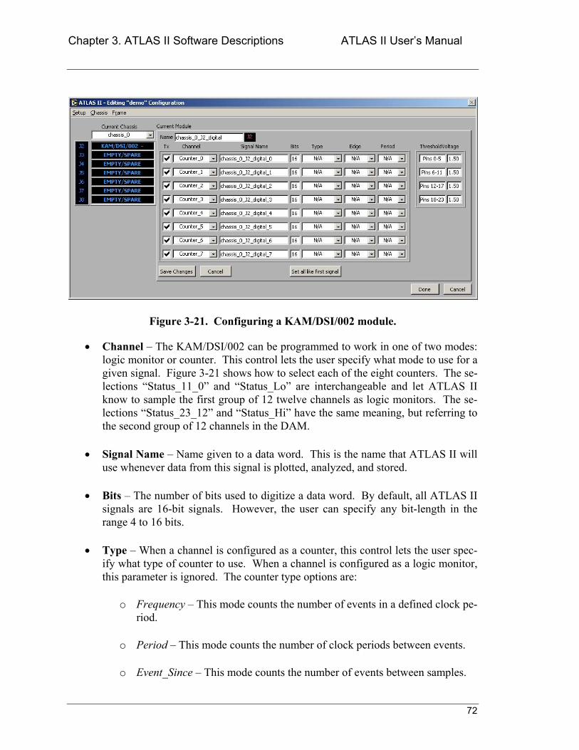
Chapter 3. ATLAS II Software Descriptions ATLAS II Users Manual
72
Figure 3-21. Configuring a KAM/DSI/002 module.
• Channel The KAM/DSI/002 can be programmed to work in one of two modes: logic monitor or counter. This control lets the user specify what mode to use for a given signal. Figure 3-21 shows how to select each of the eight counters. The se-lections Status_11_0 and Status_Lo are interchangeable and let ATLAS II know to sample the first group of 12 twelve channels as logic monitors. The se-lections Status_23_12 and Status_Hi have the same meaning, but referring to the second group of 12 channels in the DAM.
• Signal Name Name given to a data word. This is the name that ATLAS II will use whenever data from this signal is plotted, analyzed, and stored.
• Bits The number of bits used to digitize a data word. By default, all ATLAS II signals are 16-bit signals. However, the user can specify any bit-length in the range 4 to 16 bits.
• Type When a channel is configured as a counter, this control lets the user spec-ify what type of counter to use. When a channel is configured as a logic monitor, this parameter is ignored. The counter type options are:
o Frequency This mode counts the number of events in a defined clock pe-riod.
o Period This mode counts the number of clock periods between events.
o Event_Since This mode counts the number of events between samples.
Chapter 3. ATLAS II Software Descriptions ATLAS II Users Manual
73
o Elapsed This mode counts the number of defined clock periods between samples.
o Count This mode counts the number of events since power-up, updating on sample. It will rollover to zero (0) on the next count after 65,535.
o Timer This mode counts the total number of defined clock periods since the last event occurred. It is updated every sample.
o Read This mode counts the total number of samples since power-up. It will rollover to zero (0) on the next count after 65,535.
o Event This mode counts the number of samples between events, updat-ing upon sample. It resets to one (1) when a new event is detected.
• Edge The edge (of a square wave), which is considered an event. The options are: Rising and Falling.
• Period The length of a tick being counted. This parameter is very important in the setup the DSI/002 DAM. The DSI/002 will sample a counter once every period interval. This means that the user must be very careful when setting the period value so that the DAM always returns meaningful data. For example, if the frequency of a signal is to be measured, the period parameter must be set high enough to give the DAM time to detect at least a couple of transitions of the source signal. If the period is set too low, the DAM will not detect enough pulse transitions in the sampling period to calculate the correct signal frequency. The counts value in a DSI/002s counter is updated every period seconds regard-less of the systems sampling rate. If the system is sampling faster than the period interval, it will just read the same value until the DAM updates the counter again.
• ThresholdVoltage This parameter specifies the actual voltage applied to de-termine whether the channel is at logic level 1 or 0. This parameter is speci-fied for groups of four channels. A voltage within the range ±7.5Vcan be specified. If a value is specified outside that range, ATLAS II will limit the input to keep it within range.
To simplify setting up a KAM/DSI/002 DAM, ATLAS II includes the Set all like first signal button. As its name implies, clicking this button will set all of the parameters (including ThresholdVoltage) for all of the active DAMs signals to those set for the first signal. The signal name parameter will also be copied, but a _# (where # will be re-placed by the signals channel number) will be appended to every name thats created.
Chapter 3. ATLAS II Software Descriptions ATLAS II Users Manual
74
Once all bridge signal(s) have been setup, click the Save Changes button. If the DAM display is closed without saving changes, all setting changes since the last save will be lost. If the previous DAM configuration is needed, click the Cancel button.
Do not worry about the signal definition areas that are not defined (empty). ATLAS II will not acquire or transmit any signal that has either an unchecked Tx flag or one that has an empty name string.
3.3.2.7 GPS/001 - GPS receiver/timing reference module parameters
Unlike all other DAMs, ACRA Control does not manufacture the GPS/001 module. Cur-rently, Sandia National Laboratories Wind Energy Group manufactures this DAM. What sets this DAM apart from the others is that it is designed to work both as the timing source for a chassis and as a data acquisition DAM.
The GPS/001 accepts GPS signals from the GPS receiver in the DAS unit. It uses these signals to generate an acquisition clock that controls every sampling period in the DAS. Furthermore, the GPS/0001 takes care of keeping this sampling clock synchronized to the GPS source. The synchronization of the clocks to the GPS source (±microseconds) will continue for as long as the DAS unit is operational.
Even though using the GPS/001 as a timing source is what gives ATLAS II its name and separates it from other data acquisition systems, a GPS/001 DAM can be used in a DAS unit exclusively as a data acquisition module if its timing signals are not connected to the DAS encoder. In this configuration the GPS/001 can still output timing information that can be included in the data stream. However, the DAS will be using its internal clock for controlling the sampling operations of all the DAMs in the DAS.
Figure 3-22 shows the active module area of the Hardware Configuration window when configuring a KAM/GPS/001 module. The parameters available for configuration in this window are:
• Name Name used by ATLAS II to identify this module as a signal source. The user can specify any name. Do not use spaces in the name (if spaces are used, ATLAS II will replace them with underscore (_) characters).
• Transmitted signal (Tx) This flag specifies whether or not the signal to which it corresponds will be acquired and transmitted in the PCM stream. Leave the flag unchecked to remove a signal from acquisition, but keep its configuration in place for possible future use.
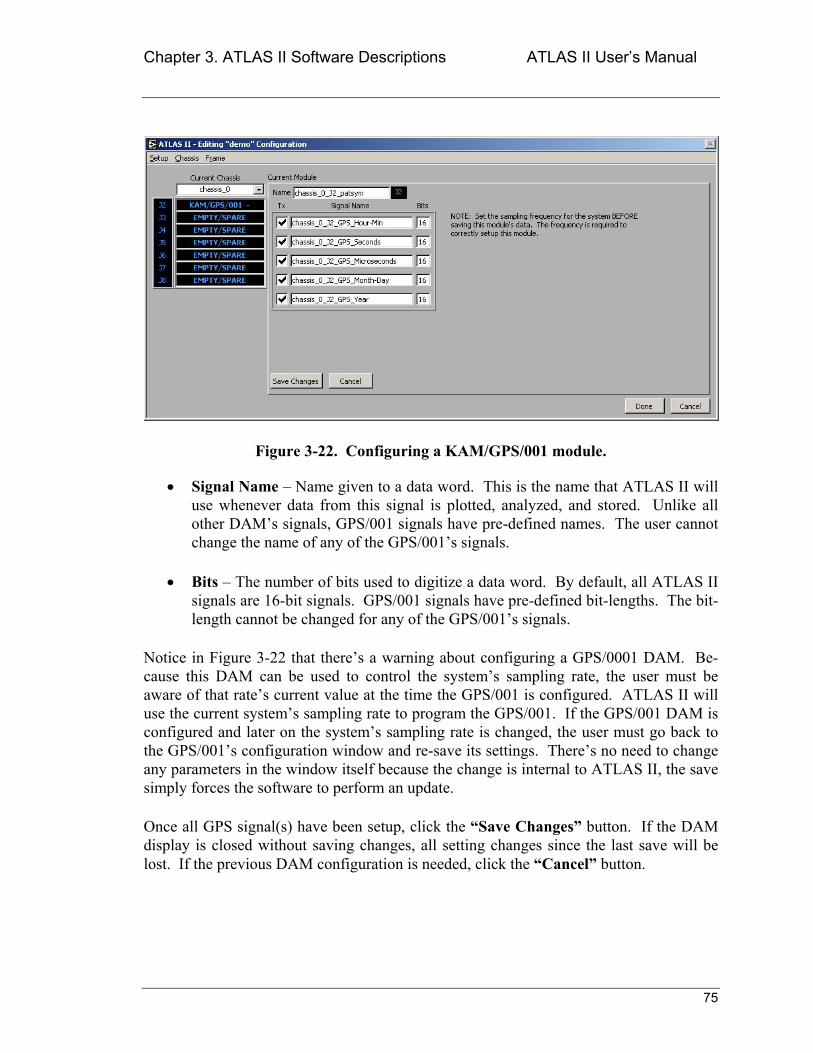
Chapter 3. ATLAS II Software Descriptions ATLAS II Users Manual
75
Figure 3-22. Configuring a KAM/GPS/001 module.
• Signal Name Name given to a data word. This is the name that ATLAS II will use whenever data from this signal is plotted, analyzed, and stored. Unlike all other DAMs signals, GPS/001 signals have pre-defined names. The user cannot change the name of any of the GPS/001s signals.
• Bits The number of bits used to digitize a data word. By default, all ATLAS II signals are 16-bit signals. GPS/001 signals have pre-defined bit-lengths. The bit-length cannot be changed for any of the GPS/001s signals.
Notice in Figure 3-22 that theres a warning about configuring a GPS/0001 DAM. Be-cause this DAM can be used to control the systems sampling rate, the user must be aware of that rates current value at the time the GPS/001 is configured. ATLAS II will use the current systems sampling rate to program the GPS/001. If the GPS/001 DAM is configured and later on the systems sampling rate is changed, the user must go back to the GPS/001s configuration window and re-save its settings. Theres no need to change any parameters in the window itself because the change is internal to ATLAS II, the save simply forces the software to perform an update.
Once all GPS signal(s) have been setup, click the Save Changes button. If the DAM display is closed without saving changes, all setting changes since the last save will be lost. If the previous DAM configuration is needed, click the Cancel button.
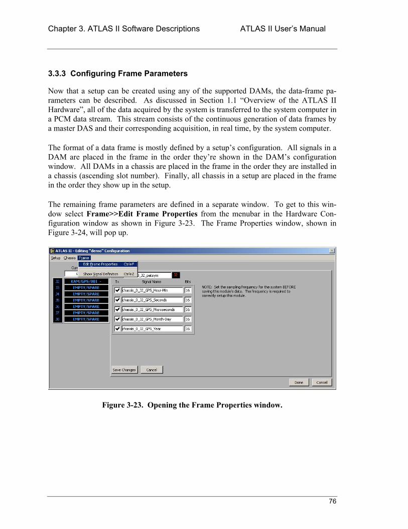
Chapter 3. ATLAS II Software Descriptions ATLAS II Users Manual
76
3.3.3 Configuring Frame Parameters
Now that a setup can be created using any of the supported DAMs, the data-frame pa-rameters can be described. As discussed in Section 1.1 Overview of the ATLAS II Hardware, all of the data acquired by the system is transferred to the system computer in a PCM data stream. This stream consists of the continuous generation of data frames by a master DAS and their corresponding acquisition, in real time, by the system computer.
The format of a data frame is mostly defined by a setups configuration. All signals in a DAM are placed in the frame in the order theyre shown in the DAMs configuration window. All DAMs in a chassis are placed in the frame in the order they are installed in a chassis (ascending slot number). Finally, all chassis in a setup are placed in the frame in the order they show up in the setup.
The remaining frame parameters are defined in a separate window. To get to this win-dow select Frame>>Edit Frame Properties from the menubar in the Hardware Con-figuration window as shown in Figure 3-23. The Frame Properties window, shown in Figure 3-24, will pop up.
Figure 3-23. Opening the Frame Properties window.
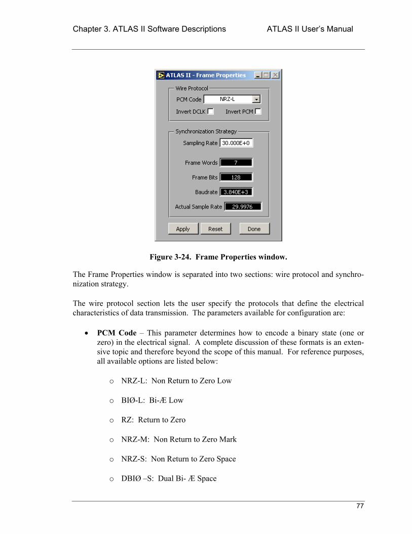
Chapter 3. ATLAS II Software Descriptions ATLAS II Users Manual
77
Figure 3-24. Frame Properties window.
The Frame Properties window is separated into two sections: wire protocol and synchro-nization strategy.
The wire protocol section lets the user specify the protocols that define the electrical characteristics of data transmission. The parameters available for configuration are:
• PCM Code This parameter determines how to encode a binary state (one or zero) in the electrical signal. A complete discussion of these formats is an exten-sive topic and therefore beyond the scope of this manual. For reference purposes, all available options are listed below:
o NRZ-L: Non Return to Zero Low
o BIØ-L: Bi-Æ Low
o RZ: Return to Zero
o NRZ-M: Non Return to Zero Mark
o NRZ-S: Non Return to Zero Space
o DBIØ S: Dual Bi- Æ Space
Chapter 3. ATLAS II Software Descriptions ATLAS II Users Manual
78
o DBIØ-M: Dual Bi- Æ Mark
o BIØ-M: Bi- Æ Mark
o BIØ-S: Bi- Æ Space
o DM-M: Delay Modulation Mark (Miller code)
o DM-S: Delay Modulation Space (Miller code)
o RNRZ-L-(11): 11-bit Random Non Return to Zero
o RNRZ-L-(13): 13-bit Random Non Return to Zero
o RNRZ-L-(15): 15-bit Random Non Return to Zero
o RNRZ-L-(17): 17-bit Random Non Return to Zero
• Invert DCLK Controls whether data clock is inverted or not.
• Invert PCM - Controls whether PCM is inverted or not.
The synchronization strategy section has only one parameter that the user can modify:
• Sampling Rate This is the system-wide sampling rate. All signals in the setup will be sampled at this rate. Any rate in the range of 1 Hz to 10000 Hz can be specified. If the value specified is outside that range, ATLAS II will limit the in-put to force it within range. Notice that even though a high sampling rate can be specified, the maximum throughput the system can support will ultimately depend on the mixture of hardware used the system configuration. As a general rule, bit-rates higher than 200 kbps are beyond the processing capabilities of a low-level PC.
Notice that there are several other parameters in this section. All those parameters (shown in white letters with a black background) are outputs of the system. They are cal-culated based on the specified system sampling rate. The parameters shown are:
• Frame Words Displays the number of data words in a single frame. This num-ber should always be at least two words larger than the number of signals in the setup. Those extra words are system words (sync word, SFID, etc.), necessary for frame synchronization.
• Frame Bits Displays the total number of bits in a single frame. This number includes bits used by the system words.
Chapter 3. ATLAS II Software Descriptions ATLAS II Users Manual
79
• Baudrate Also know as the system bit-rate, this parameter shows the total sys-tem data rate, expressed in bits per second.
• Actual Sample Rate When a sample rate is specified, ATLAS II tries to pro-gram the system in such a way that it can match all of the parameter requests. However, because of the discrete nature of the timing source, the systems actual data rate may vary from the rate requested. This control lets the user verify the difference between the requested rate and the rate the system will use.
ATLAS II allows the user to examine how changes to the sampling rate will affect the system throughput. Enter any data rate of interest and then click the Apply button. This tells ATLAS II to calculate and update all the transmission parameters. If the results meet the test criteria, click the Done button to exit this window and then select Setup>>Save from the Hardware Configuration windows menubar to save the setup. This last step is very important if the changes made are intended to be active and permanent. If the setup changes are not saved after making the changes, the Frame Prop-erties window will keep the original configuration.
If the changes made to the sampling rate produce unsatisfactory throughput parameters, click the Reset button. ATLAS II will discard the changes and re-load the last-saved (for the active setup) frame parameters.
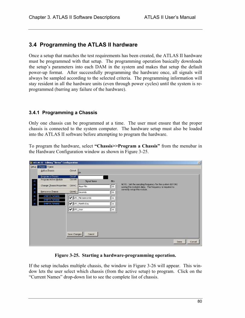
Chapter 3. ATLAS II Software Descriptions ATLAS II Users Manual
80
3.4 Programming the ATLAS II hardware
Once a setup that matches the test requirements has been created, the ATLAS II hardware must be programmed with that setup. The programming operation basically downloads the setups parameters into each DAM in the system and makes that setup the default power-up format. After successfully programming the hardware once, all signals will always be sampled according to the selected criteria. The programming information will stay resident in all the hardware units (even through power cycles) until the system is re-programmed (barring any failure of the hardware).
3.4.1 Programming a Chassis
Only one chassis can be programmed at a time. The user must ensure that the proper chassis is connected to the system computer. The hardware setup must also be loaded into the ATLAS II software before attempting to program the hardware.
To program the hardware, select Chassis>>Program a Chassis from the menubar in the Hardware Configuration window as shown in Figure 3-25.
Figure 3-25. Starting a hardware-programming operation.
If the setup includes multiple chassis, the window in Figure 3-26 will appear. This win-dow lets the user select which chassis (from the active setup) to program. Click on the Current Names drop-down list to see the complete list of chassis.
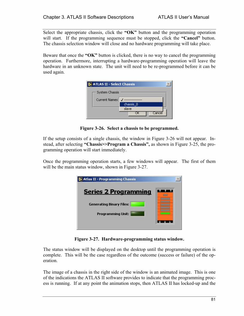
Chapter 3. ATLAS II Software Descriptions ATLAS II Users Manual
81
Select the appropriate chassis, click the OK button and the programming operation will start. If the programming sequence must be stopped, click the Cancel button. The chassis selection window will close and no hardware programming will take place.
Beware that once the OK button is clicked, there is no way to cancel the programming operation. Furthermore, interrupting a hardware-programming operation will leave the hardware in an unknown state. The unit will need to be re-programmed before it can be used again.
Figure 3-26. Select a chassis to be programmed.
If the setup consists of a single chassis, the window in Figure 3-26 will not appear. In-stead, after selecting Chassis>>Program a Chassis, as shown in Figure 3-25, the pro-gramming operation will start immediately.
Once the programming operation starts, a few windows will appear. The first of them will be the main status window, shown in Figure 3-27.
Figure 3-27. Hardware-programming status window.
The status window will be displayed on the desktop until the programming operation is complete. This will be the case regardless of the outcome (success or failure) of the op-eration.
The image of a chassis in the right side of the window is an animated image. This is one of the indications the ATLAS II software provides to indicate that the programming proc-ess is running. If at any point the animation stops, then ATLAS II has locked-up and the
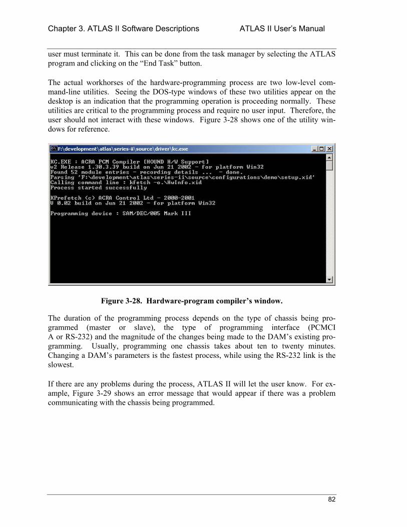
Chapter 3. ATLAS II Software Descriptions ATLAS II Users Manual
82
user must terminate it. This can be done from the task manager by selecting the ATLAS program and clicking on the End Task button.
The actual workhorses of the hardware-programming process are two low-level com-mand-line utilities. Seeing the DOS-type windows of these two utilities appear on the desktop is an indication that the programming operation is proceeding normally. These utilities are critical to the programming process and require no user input. Therefore, the user should not interact with these windows. Figure 3-28 shows one of the utility win-dows for reference.
Figure 3-28. Hardware-program compilers window.
The duration of the programming process depends on the type of chassis being pro-grammed (master or slave), the type of programming interface (PCMCI A or RS-232) and the magnitude of the changes being made to the DAMs existing pro-gramming. Usually, programming one chassis takes about ten to twenty minutes. Changing a DAMs parameters is the fastest process, while using the RS-232 link is the slowest.
If there are any problems during the process, ATLAS II will let the user know. For ex-ample, Figure 3-29 shows an error message that would appear if there was a problem communicating with the chassis being programmed.
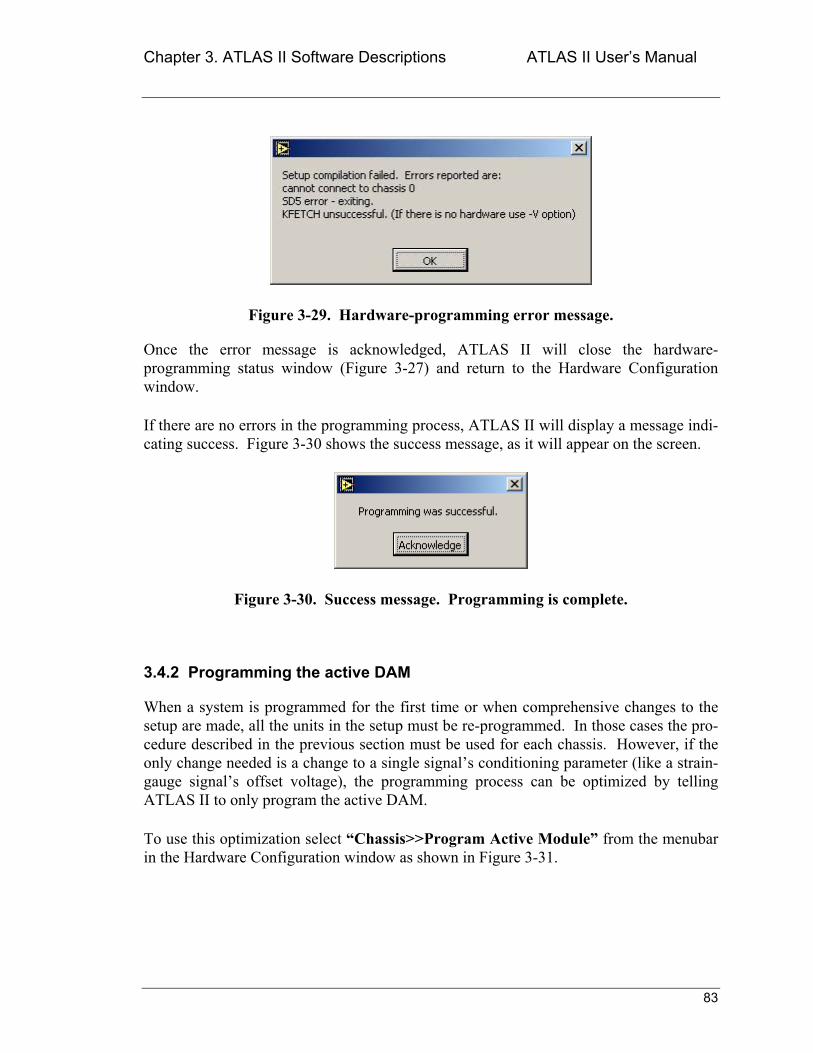
Chapter 3. ATLAS II Software Descriptions ATLAS II Users Manual
83
Figure 3-29. Hardware-programming error message.
Once the error message is acknowledged, ATLAS II will close the hardware-programming status window (Figure 3-27) and return to the Hardware Configuration window.
If there are no errors in the programming process, ATLAS II will display a message indi-cating success. Figure 3-30 shows the success message, as it will appear on the screen.
Figure 3-30. Success message. Programming is complete.
3.4.2 Programming the active DAM
When a system is programmed for the first time or when comprehensive changes to the setup are made, all the units in the setup must be re-programmed. In those cases the pro-cedure described in the previous section must be used for each chassis. However, if the only change needed is a change to a single signals conditioning parameter (like a strain-gauge signals offset voltage), the programming process can be optimized by telling ATLAS II to only program the active DAM.
To use this optimization select Chassis>>Program Active Module from the menubar in the Hardware Configuration window as shown in Figure 3-31.
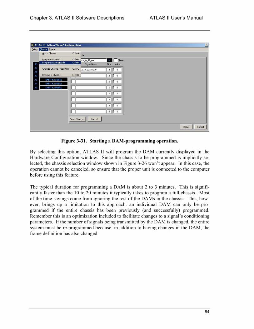
Chapter 3. ATLAS II Software Descriptions ATLAS II Users Manual
84
Figure 3-31. Starting a DAM-programming operation.
By selecting this option, ATLAS II will program the DAM currently displayed in the Hardware Configuration window. Since the chassis to be programmed is implicitly se-lected, the chassis selection window shown in Figure 3-26 wont appear. In this case, the operation cannot be canceled, so ensure that the proper unit is connected to the computer before using this feature.
The typical duration for programming a DAM is about 2 to 3 minutes. This is signifi-cantly faster than the 10 to 20 minutes it typically takes to program a full chassis. Most of the time-savings come from ignoring the rest of the DAMs in the chassis. This, how-ever, brings up a limitation to this approach: an individual DAM can only be pro-grammed if the entire chassis has been previously (and successfully) programmed. Remember this is an optimization included to facilitate changes to a signals conditioning parameters. If the number of signals being transmitted by the DAM is changed, the entire system must be re-programmed because, in addition to having changes in the DAM, the frame definition has also changed.
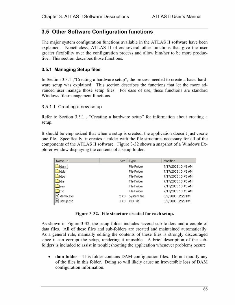
Chapter 3. ATLAS II Software Descriptions ATLAS II Users Manual
85
3.5 Other Software Configuration functions
The major system configuration functions available in the ATLAS II software have been explained. Nonetheless, ATLAS II offers several other functions that give the user greater flexibility over the configuration process and allow him/her to be more produc-tive. This section describes those functions.
3.5.1 Managing Setup files
In Section 3.3.1 ,Creating a hardware setup, the process needed to create a basic hard-ware setup was explained. This section describes the functions that let the more ad-vanced user manage those setup files. For ease of use, these functions are standard Windows file-management functions.
3.5.1.1 Creating a new setup
Refer to Section 3.3.1 , Creating a hardware setup for information about creating a setup.
It should be emphasized that when a setup is created, the application doesnt just create one file. Specifically, it creates a folder with the file structures necessary for all of the components of the ATLAS II software. Figure 3-32 shows a snapshot of a Windows Ex-plorer window displaying the contents of a setup folder.
Figure 3-32. File structure created for each setup.
As shown in Figure 3-32, the setup folder includes several sub-folders and a couple of data files. All of these files and sub-folders are created and maintained automatically. As a general rule, manually editing the contents of these files is strongly discouraged since it can corrupt the setup, rendering it unusable. A brief description of the sub-folders is included to assist in troubleshooting the application whenever problems occur:
• dam folder This folder contains DAM configuration files. Do not modify any of the files in this folder. Doing so will likely cause an irreversible loss of DAM configuration information.
Chapter 3. ATLAS II Software Descriptions ATLAS II Users Manual
86
• dds folder This folder contains display configuration files. If the files in this folder are lost, the current setup can still be used to acquire and process data. Please refer to Section 3.7.1.2 Creating a Display setup for a complete descrip-tion of display configurations.
• dps folder - This folder contains data-processing configuration files. If the files in this folder are lost, data can still be acquired, but ATLAS II will only be able to display or record raw data (use of engineering units (EU) will be disabled). Please refer to Section 3.9.1.1 Creating a processing setup for a complete de-scription of data-processing configurations.
• drs folder This folder is not used by the current version of ATLAS II. It exists for support of future application features.
• ses folder This folder contains system-events configuration files. If the files in this folder are lost, the software will still be able to acquire, display, and record data either in raw units or in EU. However, ATLAS II will loose its ability to automatically react to events detected during data acquisition. Please refer to Section 3.12 , Using System Events (Automating ATLAS II) for a complete de-scription of system events configurations.
• xid folder This folder contains the hardware-programming source files. Do not edit the files in this folder unless the ramifications of the changes are completely understood. If the files in this folder are lost, the software can still acquire and process data. However, these files must be re-created before any changes to the setups signals can be implemented.
• *.sys file The .sys file is the main setup file. It holds all of the configuration in-formation (except for specific DAM settings which are inside the dam folder). The name of the file is always the same as the setups name. If this file is dam-aged or lost, the setup will be lost.
• setup.xid file- This file is the master source file for the hardware-programming process. It has the same name in all setups. Never edit this file manually. If this file is lost, the software can still acquire and process data. However, the file must be re-created before any changes to the setups signals can be implemented.
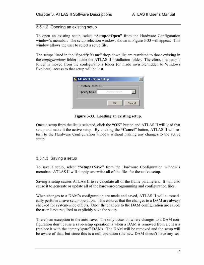
Chapter 3. ATLAS II Software Descriptions ATLAS II Users Manual
87
3.5.1.2 Opening an existing setup
To open an existing setup, select Setup>>Open from the Hardware Configuration windows menubar. The setup selection window, shown in Figure 3-33 will appear. This window allows the user to select a setup file.
The setups listed in the Specify Name drop-down list are restricted to those existing in the configurations folder inside the ATLAS II installation folder. Therefore, if a setups folder is moved from the configurations folder (or made invisible/hidden to Windows Explorer), access to that setup will be lost.
Figure 3-33. Loading an existing setup.
Once a setup from the list is selected, click the OK button and ATLAS II will load that setup and make it the active setup. By clicking the Cancel button, ATLAS II will re-turn to the Hardware Configuration window without making any changes to the active setup.
3.5.1.3 Saving a setup
To save a setup, select Setup>>Save from the Hardware Configuration windows menubar. ATLAS II will simply overwrite all of the files for the active setup.
Saving a setup causes ATLAS II to re-calculate all of the frame parameters. It will also cause it to generate or update all of the hardware-programming and configuration files.
When changes to a DAMs configuration are made and saved, ATLAS II will automati-cally perform a save-setup operation. This ensures that the changes to a DAM are always checked for system-wide effects. Once the changes to the DAM configuration are saved, the user is not required to explicitly save the setup.
Theres an exception to the auto-save. The only occasion where changes to a DAM con-figuration dont cause a save-setup operation is when a DAM is removed from a chassis (replace it with the empty/spare DAM). The DAM will be removed and the setup will be aware of that, but since this is a null operation (the new DAM doesnt have any set-
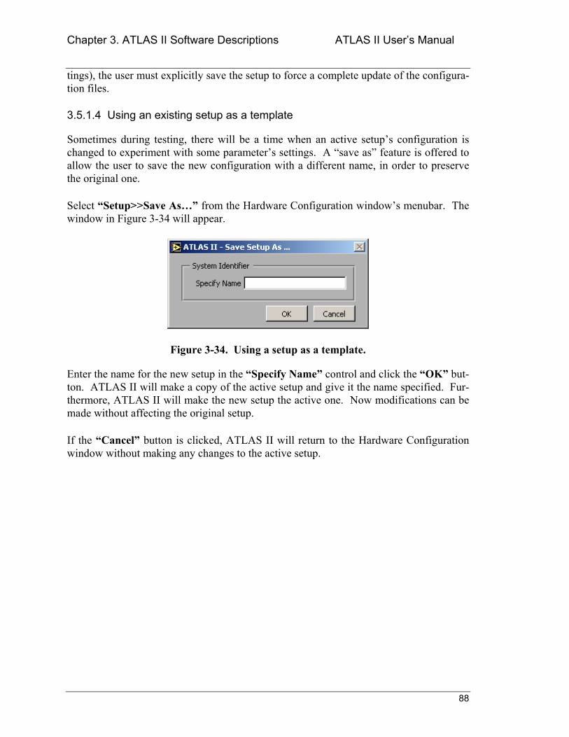
Chapter 3. ATLAS II Software Descriptions ATLAS II Users Manual
88
tings), the user must explicitly save the setup to force a complete update of the configura-tion files.
3.5.1.4 Using an existing setup as a template
Sometimes during testing, there will be a time when an active setups configuration is changed to experiment with some parameters settings. A save as feature is offered to allow the user to save the new configuration with a different name, in order to preserve the original one.
Select Setup>>Save As from the Hardware Configuration windows menubar. The window in Figure 3-34 will appear.
Figure 3-34. Using a setup as a template.
Enter the name for the new setup in the Specify Name control and click the OK but-ton. ATLAS II will make a copy of the active setup and give it the name specified. Fur-thermore, ATLAS II will make the new setup the active one. Now modifications can be made without affecting the original setup.
If the Cancel button is clicked, ATLAS II will return to the Hardware Configuration window without making any changes to the active setup.
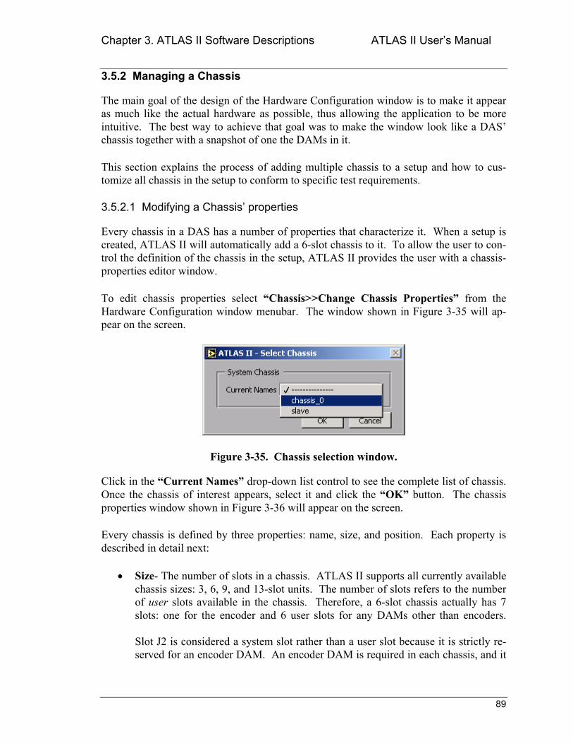
Chapter 3. ATLAS II Software Descriptions ATLAS II Users Manual
89
3.5.2 Managing a Chassis
The main goal of the design of the Hardware Configuration window is to make it appear as much like the actual hardware as possible, thus allowing the application to be more intuitive. The best way to achieve that goal was to make the window look like a DAS chassis together with a snapshot of one the DAMs in it.
This section explains the process of adding multiple chassis to a setup and how to cus-tomize all chassis in the setup to conform to specific test requirements.
3.5.2.1 Modifying a Chassis properties
Every chassis in a DAS has a number of properties that characterize it. When a setup is created, ATLAS II will automatically add a 6-slot chassis to it. To allow the user to con-trol the definition of the chassis in the setup, ATLAS II provides the user with a chassis-properties editor window.
To edit chassis properties select Chassis>>Change Chassis Properties from the Hardware Configuration window menubar. The window shown in Figure 3-35 will ap-pear on the screen.
Figure 3-35. Chassis selection window.
Click in the Current Names drop-down list control to see the complete list of chassis. Once the chassis of interest appears, select it and click the OK button. The chassis properties window shown in Figure 3-36 will appear on the screen.
Every chassis is defined by three properties: name, size, and position. Each property is described in detail next:
• Size- The number of slots in a chassis. ATLAS II supports all currently available chassis sizes: 3, 6, 9, and 13-slot units. The number of slots refers to the number of user slots available in the chassis. Therefore, a 6-slot chassis actually has 7 slots: one for the encoder and 6 user slots for any DAMs other than encoders. Slot J2 is considered a system slot rather than a user slot because it is strictly re-served for an encoder DAM. An encoder DAM is required in each chassis, and it
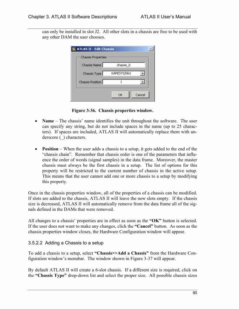
Chapter 3. ATLAS II Software Descriptions ATLAS II Users Manual
90
can only be installed in slot J2. All other slots in a chassis are free to be used with any other DAM the user chooses.
Figure 3-36. Chassis properties window.
• Name The chassis name identifies the unit throughout the software. The user can specify any string, but do not include spaces in the name (up to 25 charac-ters). If spaces are included, ATLAS II will automatically replace them with un-derscore (_) characters.
• Position When the user adds a chassis to a setup, it gets added to the end of the chassis chain. Remember that chassis order is one of the parameters that influ-ence the order of words (signal samples) in the data frame. Moreover, the master chassis must always be the first chassis in a setup. The list of options for this property will be restricted to the current number of chassis in the active setup. This means that the user cannot add one or more chassis to a setup by modifying this property.
Once in the chassis properties window, all of the properties of a chassis can be modified. If slots are added to the chassis, ATLAS II will leave the new slots empty. If the chassis size is decreased, ATLAS II will automatically remove from the data frame all of the sig-nals defined in the DAMs that were removed.
All changes to a chassis properties are in effect as soon as the OK button is selected. If the user does not want to make any changes, click the Cancel button. As soon as the chassis properties window closes, the Hardware Configuration window will appear.
3.5.2.2 Adding a Chassis to a setup
To add a chassis to a setup, select Chassis>>Add a Chassis from the Hardware Con-figuration windows menubar. The window shown in Figure 3-37 will appear.
By default ATLAS II will create a 6-slot chassis. If a different size is required, click on the Chassis Type drop-down list and select the proper size. All possible chassis sizes
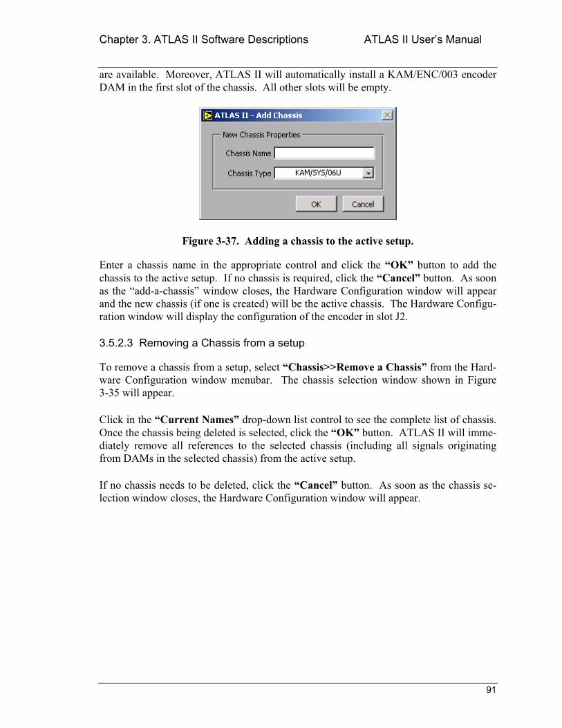
Chapter 3. ATLAS II Software Descriptions ATLAS II Users Manual
91
are available. Moreover, ATLAS II will automatically install a KAM/ENC/003 encoder DAM in the first slot of the chassis. All other slots will be empty.
Figure 3-37. Adding a chassis to the active setup.
Enter a chassis name in the appropriate control and click the OK button to add the chassis to the active setup. If no chassis is required, click the Cancel button. As soon as the add-a-chassis window closes, the Hardware Configuration window will appear and the new chassis (if one is created) will be the active chassis. The Hardware Configu-ration window will display the configuration of the encoder in slot J2.
3.5.2.3 Removing a Chassis from a setup
To remove a chassis from a setup, select Chassis>>Remove a Chassis from the Hard-ware Configuration window menubar. The chassis selection window shown in Figure 3-35 will appear.
Click in the Current Names drop-down list control to see the complete list of chassis. Once the chassis being deleted is selected, click the OK button. ATLAS II will imme-diately remove all references to the selected chassis (including all signals originating from DAMs in the selected chassis) from the active setup.
If no chassis needs to be deleted, click the Cancel button. As soon as the chassis se-lection window closes, the Hardware Configuration window will appear.
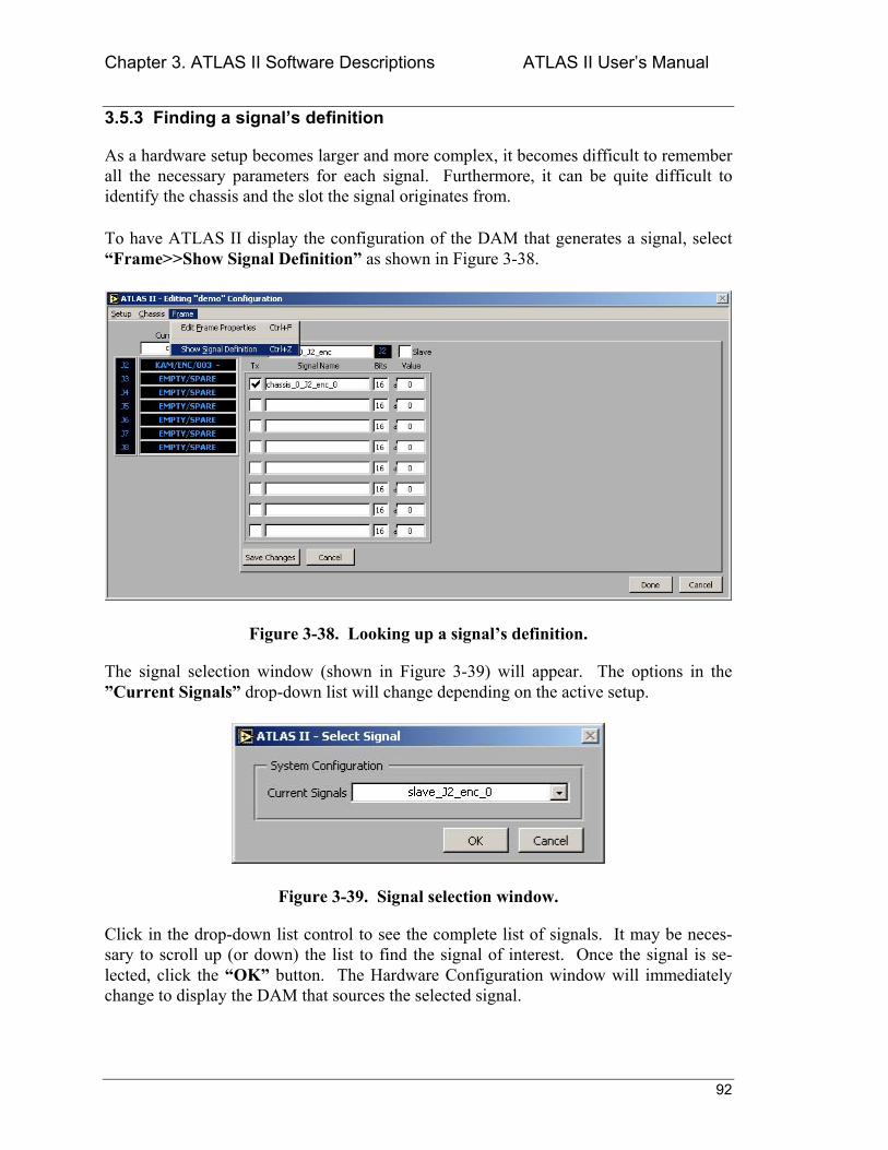
Chapter 3. ATLAS II Software Descriptions ATLAS II Users Manual
92
3.5.3 Finding a signals definition
As a hardware setup becomes larger and more complex, it becomes difficult to remember all the necessary parameters for each signal. Furthermore, it can be quite difficult to identify the chassis and the slot the signal originates from.
To have ATLAS II display the configuration of the DAM that generates a signal, select Frame>>Show Signal Definition as shown in Figure 3-38.
Figure 3-38. Looking up a signals definition.
The signal selection window (shown in Figure 3-39) will appear. The options in the Current Signals drop-down list will change depending on the active setup.
Figure 3-39. Signal selection window.
Click in the drop-down list control to see the complete list of signals. It may be neces-sary to scroll up (or down) the list to find the signal of interest. Once the signal is se-lected, click the OK button. The Hardware Configuration window will immediately change to display the DAM that sources the selected signal.
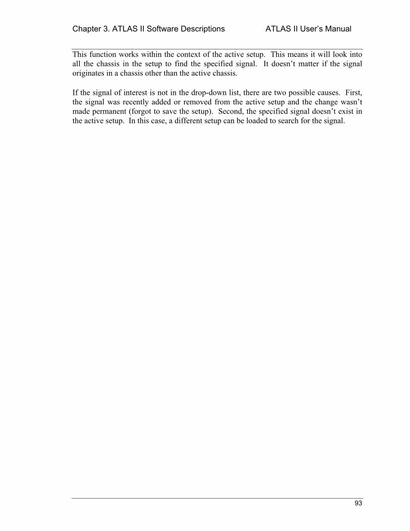
Chapter 3. ATLAS II Software Descriptions ATLAS II Users Manual
93
This function works within the context of the active setup. This means it will look into all the chassis in the setup to find the specified signal. It doesnt matter if the signal originates in a chassis other than the active chassis.
If the signal of interest is not in the drop-down list, there are two possible causes. First, the signal was recently added or removed from the active setup and the change wasnt made permanent (forgot to save the setup). Second, the specified signal doesnt exist in the active setup. In this case, a different setup can be loaded to search for the signal.
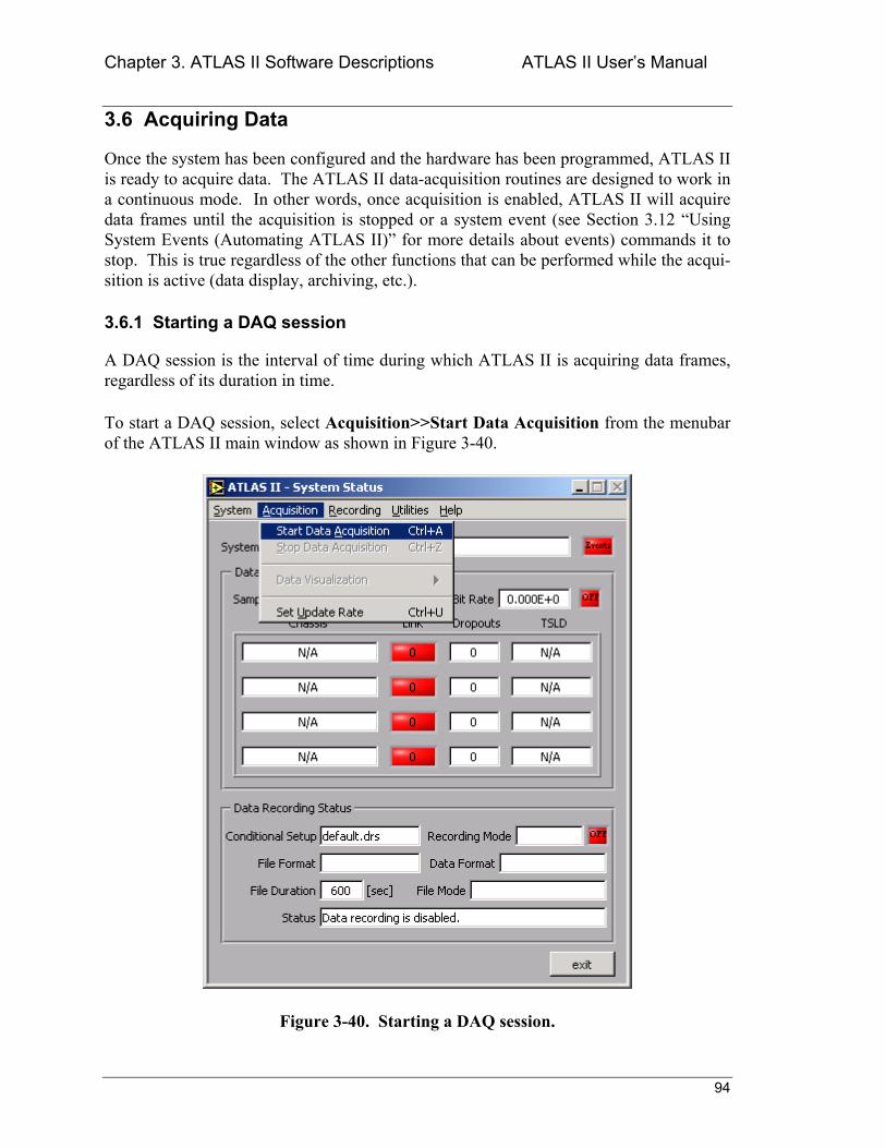
Chapter 3. ATLAS II Software Descriptions ATLAS II Users Manual
94
3.6 Acquiring Data
Once the system has been configured and the hardware has been programmed, ATLAS II is ready to acquire data. The ATLAS II data-acquisition routines are designed to work in a continuous mode. In other words, once acquisition is enabled, ATLAS II will acquire data frames until the acquisition is stopped or a system event (see Section 3.12 Using System Events (Automating ATLAS II) for more details about events) commands it to stop. This is true regardless of the other functions that can be performed while the acqui-sition is active (data display, archiving, etc.).
3.6.1 Starting a DAQ session
A DAQ session is the interval of time during which ATLAS II is acquiring data frames, regardless of its duration in time.
To start a DAQ session, select Acquisition>>Start Data Acquisition from the menubar of the ATLAS II main window as shown in Figure 3-40.
Figure 3-40. Starting a DAQ session.
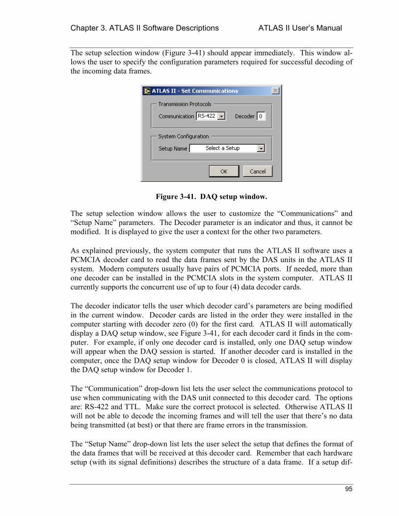
Chapter 3. ATLAS II Software Descriptions ATLAS II Users Manual
95
The setup selection window (Figure 3-41) should appear immediately. This window al-lows the user to specify the configuration parameters required for successful decoding of the incoming data frames.
Figure 3-41. DAQ setup window.
The setup selection window allows the user to customize the Communications and Setup Name parameters. The Decoder parameter is an indicator and thus, it cannot be modified. It is displayed to give the user a context for the other two parameters.
As explained previously, the system computer that runs the ATLAS II software uses a PCMCIA decoder card to read the data frames sent by the DAS units in the ATLAS II system. Modern computers usually have pairs of PCMCIA ports. If needed, more than one decoder can be installed in the PCMCIA slots in the system computer. ATLAS II currently supports the concurrent use of up to four (4) data decoder cards.
The decoder indicator tells the user which decoder cards parameters are being modified in the current window. Decoder cards are listed in the order they were installed in the computer starting with decoder zero (0) for the first card. ATLAS II will automatically display a DAQ setup window, see Figure 3-41, for each decoder card it finds in the com-puter. For example, if only one decoder card is installed, only one DAQ setup window will appear when the DAQ session is started. If another decoder card is installed in the computer, once the DAQ setup window for Decoder 0 is closed, ATLAS II will display the DAQ setup window for Decoder 1.
The Communication drop-down list lets the user select the communications protocol to use when communicating with the DAS unit connected to this decoder card. The options are: RS-422 and TTL. Make sure the correct protocol is selected. Otherwise ATLAS II will not be able to decode the incoming frames and will tell the user that theres no data being transmitted (at best) or that there are frame errors in the transmission.
The Setup Name drop-down list lets the user select the setup that defines the format of the data frames that will be received at this decoder card. Remember that each hardware setup (with its signal definitions) describes the structure of a data frame. If a setup dif-
Chapter 3. ATLAS II Software Descriptions ATLAS II Users Manual
96
ferent from the one actually programmed in the hardware is selected, ATLAS II will not be able to successfully decode the incoming data frames, and as with the Communica-tion parameter, ATLAS II will tell the user that no data is being transmitted (at best) or that there are frame errors in the transmission. Acquisition from a properly configured decoder-DAS pair is typically error-free.
Once the correct setup is selected, click the OK button. ATLAS II will immediately look for data frames to decode and process. If at any time ATLAS II appears to be locked-up after clicking the OK button, there are probably no data frames coming in. Check that the appropriate decoder card is connected to a DAS unit and that the DAS unit is powered on.
If no data is to be acquired from a specific decoder, click the Cancel button in the DAQ setup window for that decoder. The user is not required to always acquire data from all installed decoder cards. Just make sure that each data stream is coming into the appropriate decoder card.
After closing the DAQ setup window(s), ATLAS II will return to the main window. This time, however, the user should see data acquisition status information continuously up-dating the main window. An example is shown in Figure 3-42.
3.6.2 Stopping a DAQ session
As soon as a DAQ session is started, ATLAS II updates the Acquisition menu in the main window to reflect the new system state. One of the changes implemented is that the Start Data Acquisition menu option will be disabled and the Stop Data Acquisi-tion option next to it will be enabled.
To stop a DAQ session, select Acquisition>>Stop Data Acquisition from the menubar of the ATLAS II main window. The activity LED in the main window should turn red immediately. All DAQ status information should be set to the default values and the main window will look as if the application just started.
Stopping the data acquisition does not stop data recording. However, if data acquisition will not be re-activated soon, data recording should be stopped since ATLAS II will not receive additional data frames to record.
Another way data acquisition can be stopped is by exiting the application. Before it ter-minates, ATLAS II will attempt to stop all on-going processes (acquisition, display, re-cording, etc.). This is not the best way to terminate these processes since they are in effect being aborted, but there will be no data corruption by exiting this way.
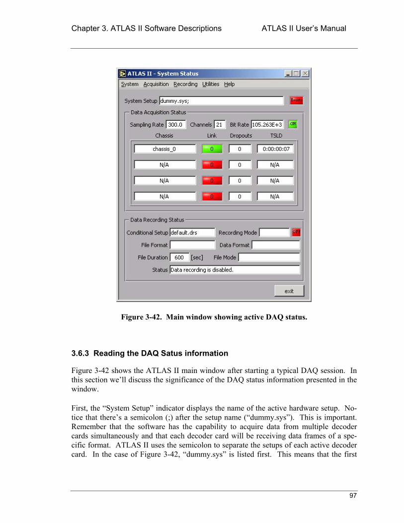
Chapter 3. ATLAS II Software Descriptions ATLAS II Users Manual
97
Figure 3-42. Main window showing active DAQ status.
3.6.3 Reading the DAQ Satus information
Figure 3-42 shows the ATLAS II main window after starting a typical DAQ session. In this section well discuss the significance of the DAQ status information presented in the window.
First, the System Setup indicator displays the name of the active hardware setup. No-tice that theres a semicolon (;) after the setup name (dummy.sys). This is important. Remember that the software has the capability to acquire data from multiple decoder cards simultaneously and that each decoder card will be receiving data frames of a spe-cific format. ATLAS II uses the semicolon to separate the setups of each active decoder card. In the case of Figure 3-42, dummy.sys is listed first. This means that the first
Chapter 3. ATLAS II Software Descriptions ATLAS II Users Manual
98
decoder card is currently configured to decode data frames defined according to the dummy hardware setup.
The semicolon after the first setup name tells the user that there is a second decoder card in the computer. However, by not listing another setup name after the semicolon, ATLAS II is telling the user that the second decoder card is not active in the current DAQ session.
If a DAQ session is started in a configuration where the first decoder card is not used, but the second card is used, ATLAS II will display the semicolon before the setup name. If a DAQ session is initiated were two decoder cards are used, ATLAS II will display two setup names separated by a semicolon. The order of the setup names corresponds with the order of the decoder cards.
The next portion of DAQ status information displays the system values for the following parameters: sampling rate, channels, and bit rate. These are called system values be-cause they reflect the total system load for the DAQ session instead of the values for any particular setup. If the DAQ session uses a single decoder card, theres only one active setup and therefore the values for the three parameters will reflect those of the active setup. However, if the DAQ session uses multiple decoder cards, there will be multiple active setups and the values for the three parameters will be the sum of the values of each setup.
Of course, the systems sampling rate is not additive. This parameter will be the same regardless of the number of decoder cards active in the DAQ session. This brings up the issue that data should not be acquired simultaneously from setups that have different sampling rates. Although ATLAS II does not prevent the user from doing it, it would be nearly impossible to make sense of the timing of the data frames from the different de-coder cards.
The other two parameters (channels and bit-rate) are additive parameters. This means that ATLAS II will display in the main window the sum of the values of each active setup. If the DAQ session has two active setups with the following parameters,
• Setup A: channels 30, bit-rate 45kbps
• Setup B: channels 92, bit-rate 140kbps
Then ATLAS II will show system values of 122 channels and 185kbps.
Next to the Bit-rate indicator in the window is the activity LED. In Figure 3-42 the LED is shown with green color and the text ON. This is the way it should look after a DAQ session has begun. ATLAS II is currently acquiring data and that the rest of the main windows DAQ status information is relevant.
Chapter 3. ATLAS II Software Descriptions ATLAS II Users Manual
99
If the activity LED is red after ATLAS II has started a DAQ session, ATLAS II could not successfully start the acquisition process. In this case there will be no data updates be-cause the DAQ session was never started. Failure to start a DAQ session suggests that there is a problem with one or more decoder cards.
After a DAQ session has been started successfully, the user can look at the table section for details about every DAS units status. This section of the window can display status information of up to four (4) DAS units. The units are listed in the order they were con-figured in the setup. Furthermore, multiple setups are listed in the same order they have in the System Setup display. If the DAQ session is acquiring data from two setups with the following units,
• Setup A units: chassis_0, chassis_1
• Setup B units: master, slave
The units will be listed as chassis_0, chassis_1, master, and slave in the status table (as-suming Setup A is being decoded by card0 and Setup B by card1).
All of the information in the table section of the window is updated every time a data frame is read. If everything is OK, the user will see status updates showing up at a con-stant rate. If no updates are occurring, there is a problem in the system. More than likely the software has stopped receiving data frames because of a power failure or a bad con-nection. Check all the communications connections and verify all the units are powered on before trying to make any changes to the software.
The first status parameter for each chassis is its Link status. If the indicator is green, there is no problem communicating with that chassis. If the indicator is red, the commu-nications link with the chassis has been broken. This status is a snapshot, i.e., it tells the instantaneous status of the link. To determine long-term trends, a backlog number is dis-played in the center of the Link indicator.
The backlog is a measure of the efficiency of communications with a chassis. This num-ber indicates the number of data frames that are currently sitting in the decoder cards internal buffer. Ideally this number should always be at zero. This condition means the application is keeping up with data transmissions from the chassis. Obviously, the sys-tem can sustain that condition forever. On the other hand, if the backlog number is con-tinuously increasing, it means data frames are accumulating in the decoder cards buffer. Since the cards buffer is finite, this condition is not sustainable. If it continues, it will get to a point were the buffer will eventually be full. When this happens, the card will discard the whole buffer to make space for the incoming data frames. Hundreds (maybe thousands, depending on the setups characteristics) of data frames can be lost every time this overflow happens.
Chapter 3. ATLAS II Software Descriptions ATLAS II Users Manual
100
It should be emphasized that only a continuously increasing backlog number that is bad. It is completely normal for the backlog to momentarily increase depending on the load on the system computer (the number of tasks active at a time). In these cases, the backlog can increase by hundreds of frames, but it should then start decreasing until it eventually gets back to zero. The backlog indicator should not be of concern until it is seconds away for an overflow condition. Moreover, a backlog that is not zero, but is constant (as-sume it always stays at 87 frames) is also not a problem because the system can sustain that condition indefinitely. Those 87 frames (in this example) will not be lost or out of order, and will be processed as soon as the system has the resources to do so (which may be just after the user tells it to stop acquiring data). The user must still check the system to prevent the condition from deteriorating.
Next to the Link/Backlog indicator is the Dropouts indicator. A dropout is defined as an instance where communications problems with the chassis cause the loss of one or more data frame. A dropout can be thought of as the condition that causes the Link indicator to turn red. The Dropouts indicator tells the user how many instances of improper commu-nications have been detected since the start of the DAQ session.
Even though, in most cases, it is not acceptable to lose even a single data frame, a non-zero Dropouts indicator does not necessarily mean trouble. For instance, it is possible for the system to detect a few Dropout conditions (around five) shortly after power has been applied to the chassis. In addition, Dropouts may have happened at an early stage of the process (and their source is eliminated afterwards) and the system could have been run-ning error-free for hours or days since.
To help put in context the effect of Dropouts, ATLAS II offers the TSLD parameter. The name stands for Time-Since-Last-Dropout. It is a counter that starts counting when a DAQ session is started and resets every time a Dropout is detected. As mentioned in the previous paragraph, the system may not be having problems if the Dropouts indicator is 43, and the TSLD shows 12 days.
The format of the TSLD indicator is Days:Hours:Minutes:Seconds. This allows ATLAS II to keep tabs on long-term DAQ sessions without losing the time resolution needed to detect high-frequency Dropout occurrences. As is the case with the other status parame-ters, the TSLD is updated continuously at a rate of once every second.
Using Figure 3-42 as our reference again, notice that theres only one chassis listed: chas-sis_0. The other entries in the status table are N/A. This means there is only one ac-tive chassis in the current DAQ session. This should agree with the contents of the active setup(s). All chassis included in all active setups should each have an entry in the status table.
Chapter 3. ATLAS II Software Descriptions ATLAS II Users Manual
101
3.7 Displaying Data
As mentioned earlier, when a DAQ session is started, ATLAS II updates the Acquisi-tion menu in the main window to reflect the new system state. One of the changes im-plemented is that the Data Visualization sub-menu will be enabled. This sub-menu is enabled only during data acquisition. As soon as the acquisition is stopped, ATLAS II will disable the menu.
The Data Visualization sub-menu has two options: Display Digital Data and Display Graphical Data. Figure 3-43 shows a screen snapshot of the sub-menu. The two options in the sub-menu are exclusive. This is because the options allows the user to configure the data display mode. ATLAS II will pass the mode information to the data visualization component, which will then adjust itself accordingly.
The user is allowed to change the selection at any time without affecting the application. Both options are discussed in the next section.
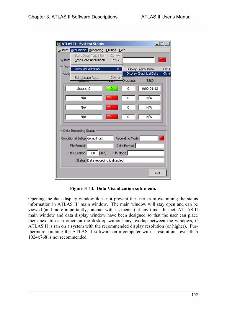
Chapter 3. ATLAS II Software Descriptions ATLAS II Users Manual
102
Figure 3-43. Data Visualization sub-menu.
Opening the data display window does not prevent the user from examining the status information in ATLAS II main window. The main window will stay open and can be viewed (and more importantly, interact with its menus) at any time. In fact, ATLAS II main window and data display window have been designed so that the user can place them next to each other on the desktop without any overlap between the windows, if ATLAS II is ran on a system with the recommended display resolution (or higher). Fur-thermore, running the ATLAS II software on a computer with a resolution lower than 1024x768 is not recommended.
Chapter 3. ATLAS II Software Descriptions ATLAS II Users Manual
103
3.7.1 Displaying Graphical Data
To display graphical data, select Acquisition>>Data Visualization>>Display Graphi-cal Data from the menubar of ATLAS II main window. The data display window shown in Figure 3-44 should appear immediately.
When data monitoring is completed, click the Close Display Window button to close the data display window.
The window in Figure 3-44 shows a typical display. When the window is opened for the first time, no data signal will be displayed, since the user must specify which signals to display.
3.7.1.1 Display/Monitor a signal
The data display window allows the user to monitor the current readings of up to eight (8) signals simultaneously in real-time. The top-left side of the data display window has eight drop-down signal-list controls to permit selection of the signals to monitor. Each of these controls has the complete list of signals from the active setup(s). By default, all controls are set to none which means no signal is being displayed.
To view a signal in both the digital display and the graph, click on one of the signal-list controls and select a signal from the drop-down list. As soon as the selection is made, ATLAS II will start updating the signals current value in the digital indicator right next to the signal-list control where the signal was selected.
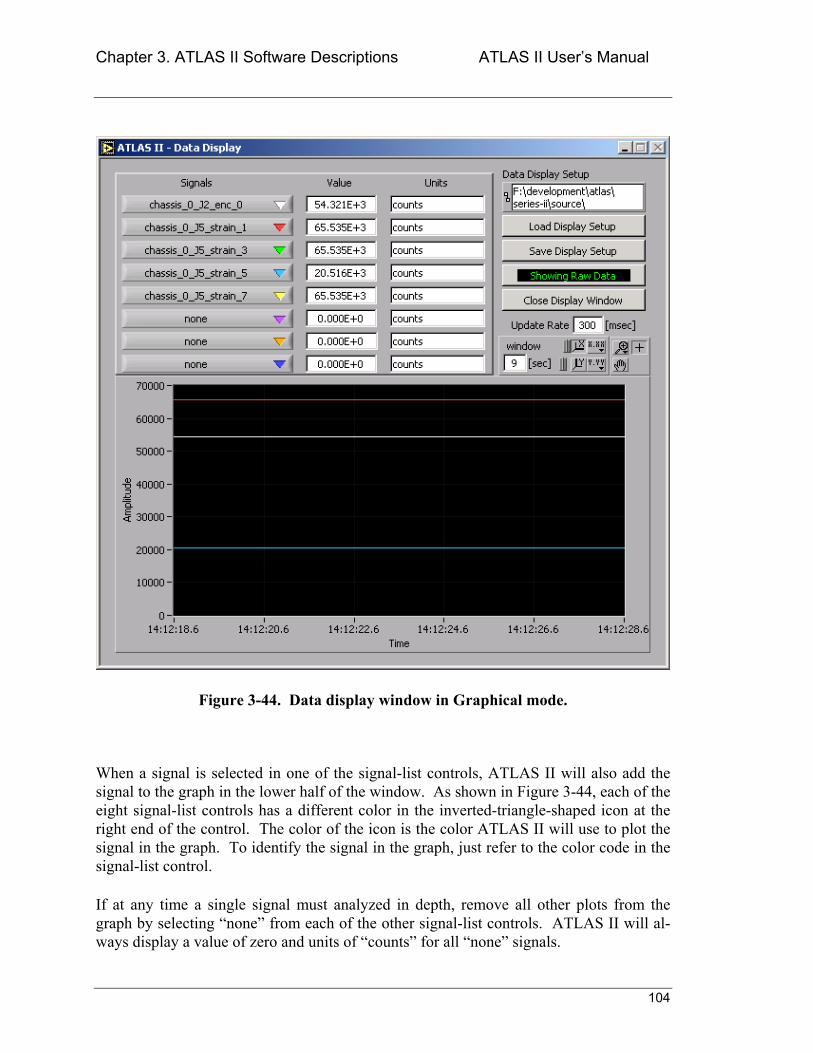
Chapter 3. ATLAS II Software Descriptions ATLAS II Users Manual
104
Figure 3-44. Data display window in Graphical mode.
When a signal is selected in one of the signal-list controls, ATLAS II will also add the signal to the graph in the lower half of the window. As shown in Figure 3-44, each of the eight signal-list controls has a different color in the inverted-triangle-shaped icon at the right end of the control. The color of the icon is the color ATLAS II will use to plot the signal in the graph. To identify the signal in the graph, just refer to the color code in the signal-list control.
If at any time a single signal must analyzed in depth, remove all other plots from the graph by selecting none from each of the other signal-list controls. ATLAS II will al-ways display a value of zero and units of counts for all none signals.
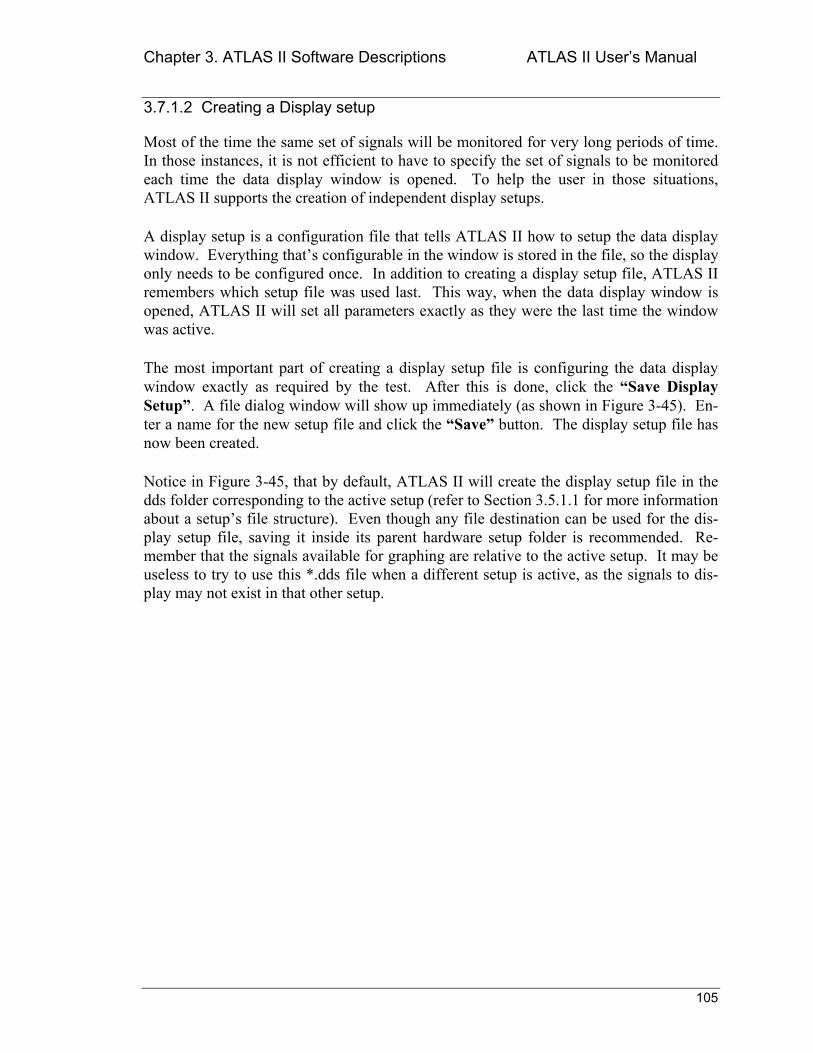
Chapter 3. ATLAS II Software Descriptions ATLAS II Users Manual
105
3.7.1.2 Creating a Display setup
Most of the time the same set of signals will be monitored for very long periods of time. In those instances, it is not efficient to have to specify the set of signals to be monitored each time the data display window is opened. To help the user in those situations, ATLAS II supports the creation of independent display setups.
A display setup is a configuration file that tells ATLAS II how to setup the data display window. Everything thats configurable in the window is stored in the file, so the display only needs to be configured once. In addition to creating a display setup file, ATLAS II remembers which setup file was used last. This way, when the data display window is opened, ATLAS II will set all parameters exactly as they were the last time the window was active.
The most important part of creating a display setup file is configuring the data display window exactly as required by the test. After this is done, click the Save Display Setup. A file dialog window will show up immediately (as shown in Figure 3-45). En-ter a name for the new setup file and click the Save button. The display setup file has now been created.
Notice in Figure 3-45, that by default, ATLAS II will create the display setup file in the dds folder corresponding to the active setup (refer to Section 3.5.1.1 for more information about a setups file structure). Even though any file destination can be used for the dis-play setup file, saving it inside its parent hardware setup folder is recommended. Re-member that the signals available for graphing are relative to the active setup. It may be useless to try to use this *.dds file when a different setup is active, as the signals to dis-play may not exist in that other setup.
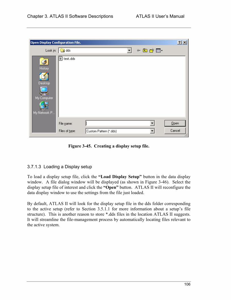
Chapter 3. ATLAS II Software Descriptions ATLAS II Users Manual
106
Figure 3-45. Creating a display setup file.
3.7.1.3 Loading a Display setup
To load a display setup file, click the Load Display Setup button in the data display window. A file dialog window will be displayed (as shown in Figure 3-46). Select the display setup file of interest and click the Open button. ATLAS II will reconfigure the data display window to use the settings from the file just loaded.
By default, ATLAS II will look for the display setup file in the dds folder corresponding to the active setup (refer to Section 3.5.1.1 for more information about a setups file structure). This is another reason to store *.dds files in the location ATLAS II suggests. It will streamline the file-management process by automatically locating files relevant to the active system.
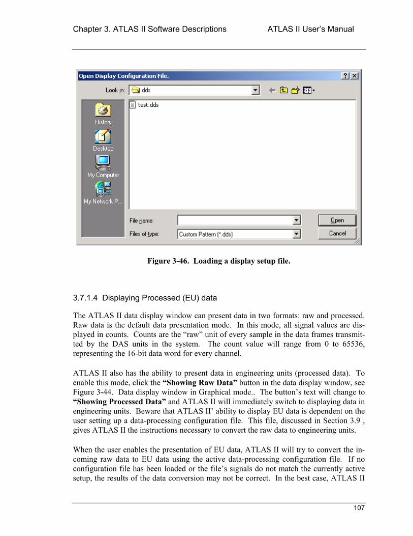
Chapter 3. ATLAS II Software Descriptions ATLAS II Users Manual
107
Figure 3-46. Loading a display setup file.
3.7.1.4 Displaying Processed (EU) data
The ATLAS II data display window can present data in two formats: raw and processed. Raw data is the default data presentation mode. In this mode, all signal values are dis-played in counts. Counts are the raw unit of every sample in the data frames transmit-ted by the DAS units in the system. The count value will range from 0 to 65536, representing the 16-bit data word for every channel.
ATLAS II also has the ability to present data in engineering units (processed data). To enable this mode, click the Showing Raw Data button in the data display window, see Figure 3-44. Data display window in Graphical mode.. The buttons text will change to Showing Processed Data and ATLAS II will immediately switch to displaying data in engineering units. Beware that ATLAS II ability to display EU data is dependent on the user setting up a data-processing configuration file. This file, discussed in Section 3.9 , gives ATLAS II the instructions necessary to convert the raw data to engineering units.
When the user enables the presentation of EU data, ATLAS II will try to convert the in-coming raw data to EU data using the active data-processing configuration file. If no configuration file has been loaded or the files signals do not match the currently active setup, the results of the data conversion may not be correct. In the best case, ATLAS II
Chapter 3. ATLAS II Software Descriptions ATLAS II Users Manual
108
will display raw data instead of EU data. In the worst case, ATLAS II will display a value of zero for a signal for which theres no entry in the data-processing configuration file.
3.7.1.5 Customizing the Graphing window
The ATLAS II data display window can be customized to provide the user with the best data visualization experience for the test data. Instead of being a one-size-fits-all design, the user can change the amount of data ATLAS II displays to enable the software to keep up with the test requirements.
The Update Rate control in the right-center section of the window is the most impor-tant tool. This control sets the duration of the system update cycle. Update Rate is ex-pressed in milliseconds/update. For example, an Update Rate of 300 milliseconds will cause ATLAS II to refresh the data display window (both digital and graphical compo-nents) once every 300 milliseconds. This does not mean that data acquisition is going to slow down (or speed up for that matter). Update Rate only changes how much new data will be presented with each refresh of the graph. Moreover, it defines how fast new val-ues will be presented in the digital indicators. The Update Rate has a range of 10-10,000 milliseconds.
Below the Update Rate control is another control called window. This parameter con-trols the size (in seconds) of the graph window, in other words, the size of the time slice that will be presented in the data graph. If the test data measures low frequency events, a longer time will be needed to capture enough data to see an event. Conversely, if the test data measures high frequency events, only a brief instant should be shown to be able to discriminate the details in the data. The window parameter lets the user cus-tomize the graph display to accommodate any type of test data.
3.7.1.6 Optimizing the Displays performance
Now that most of the ATLAS II main features have been described, it is appropriate to discuss how the systems parameters interact with one another.
The previous section presented a discussion of a couple of parameters that control how ATLAS II displays data. It has also been mentioned that ATLAS II provides two differ-ent display options. The next step is to discuss how changes in these parameters affect ATLAS II response time. Remember, all of these parameters work within the context of a hardware setup.
An important parameter to keep in mind is the systems bit-rate. This rate is the systems throughput and is constant and continuous throughout a DAQ Session. This means that with no other features active, the ATLAS II system will be loaded to varying degrees ac-cording to the active setups bit-rate. Displaying data, whether digitally or graphically only adds to the systems load.
Chapter 3. ATLAS II Software Descriptions ATLAS II Users Manual
109
By default, ATLAS II operates with an update rate of 300 milliseconds. This rate is ap-propriate for most relatively slow systems (systems whose bit-rate is less than 100 kbps). However, if the setup defines a higher bit-rate, the user may notice that the backlog indi-cator in the main screen starts to increase with time. When this happens, the first re-sponse should be to close the data display window to measure the effect of that process on the system load.
If closing the data display window has a significant effect on the system load, minimize the impact of data visualization by only displaying digital data. If displaying only digital data is not sufficient to stabilize the system backlog, the next step is to modify the system update rate. Try to use an update rate that is a multiple of the sampling rate. This pro-duces a fundamental size for a data block and will help simplify finding the optimum up-date rate.
If closing the data display window doesnt have a significant effect on the system load, the system is at its maximum load level. In this case the systems sampling rate should be decreased. Reducing the sampling rate will decrease the systems bit-rate. If it is not possible to decrease the sampling rate, consider upgrading the system computer to obtain additional resources.
The most important thing to remember is that ATLAS II is flexible enough to help the user balance the test requirements with the system computers available resources.
3.7.2 Displaying Digital Data
To display digital data, select Acquisition>>Data Visualization>>Display Digital Data from the menubar of ATLAS II main window. The data display window shown in Figure 3-47 should appear immediately.
After data monitoring is complete, click the Close Display Window button to close the data display window.
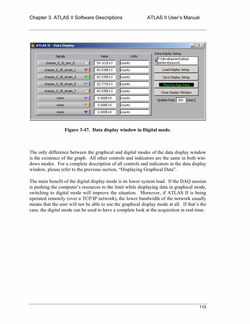
Chapter 3. ATLAS II Software Descriptions ATLAS II Users Manual
110
Figure 3-47. Data display window in Digital mode.
The only difference between the graphical and digital modes of the data display window is the existence of the graph. All other controls and indicators are the same in both win-dows modes. For a complete description of all controls and indicators in the data display window, please refer to the previous section, Displaying Graphical Data.
The main benefit of the digital display mode is its lower system load. If the DAQ session is pushing the computers resources to the limit while displaying data in graphical mode, switching to digital mode will improve the situation. Moreover, if ATLAS II is being operated remotely (over a TCP/IP network), the lower bandwidth of the network usually means that the user will not be able to use the graphical display mode at all. If thats the case, the digital mode can be used to have a complete look at the acquisition in real-time.
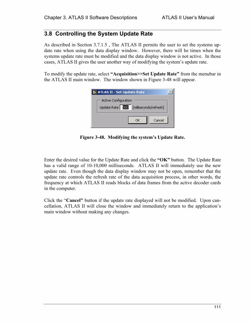
Chapter 3. ATLAS II Software Descriptions ATLAS II Users Manual
111
3.8 Controlling the System Update Rate
As described in Section 3.7.1.5 , The ATLAS II permits the user to set the systems up-date rate when using the data display window. However, there will be times when the systems update rate must be modified and the data display window is not active. In those cases, ATLAS II gives the user another way of modifying the systems update rate.
To modify the update rate, select Acquisition>>Set Update Rate from the menubar in the ATLAS II main window. The window shown in Figure 3-48 will appear.
Figure 3-48. Modifying the systems Update Rate.
Enter the desired value for the Update Rate and click the OK button. The Update Rate has a valid range of 10-10,000 milliseconds. ATLAS II will immediately use the new update rate. Even though the data display window may not be open, remember that the update rate controls the refresh rate of the data acquisition process, in other words, the frequency at which ATLAS II reads blocks of data frames from the active decoder cards in the computer.
Click the Cancel button if the update rate displayed will not be modified. Upon can-cellation, ATLAS II will close the window and immediately return to the applications main window without making any changes.
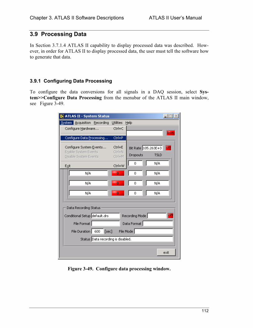
Chapter 3. ATLAS II Software Descriptions ATLAS II Users Manual
112
3.9 Processing Data
In Section 3.7.1.4 ATLAS II capability to display processed data was described. How-ever, in order for ATLAS II to display processed data, the user must tell the software how to generate that data.
3.9.1 Configuring Data Processing
To configure the data conversions for all signals in a DAQ session, select Sys-tem>>Configure Data Processing from the menubar of the ATLAS II main window, see Figure 3-49.
Figure 3-49. Configure data processing window.
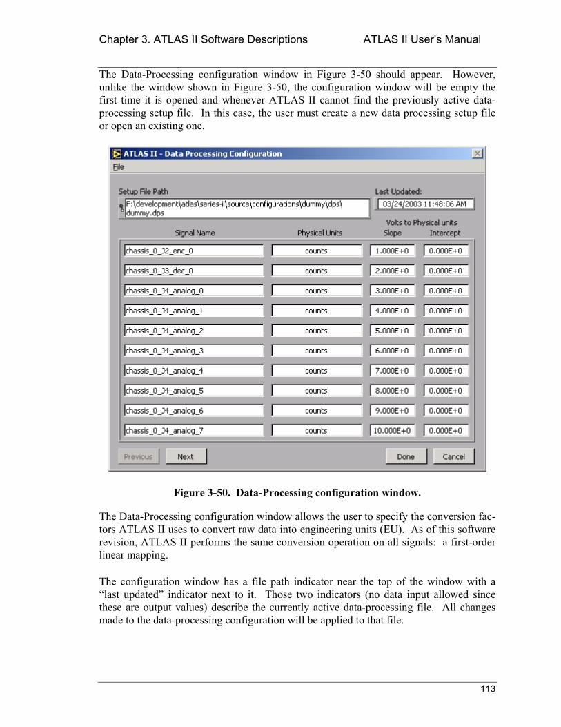
Chapter 3. ATLAS II Software Descriptions ATLAS II Users Manual
113
The Data-Processing configuration window in Figure 3-50 should appear. However, unlike the window shown in Figure 3-50, the configuration window will be empty the first time it is opened and whenever ATLAS II cannot find the previously active data-processing setup file. In this case, the user must create a new data processing setup file or open an existing one.
Figure 3-50. Data-Processing configuration window.
The Data-Processing configuration window allows the user to specify the conversion fac-tors ATLAS II uses to convert raw data into engineering units (EU). As of this software revision, ATLAS II performs the same conversion operation on all signals: a first-order linear mapping.
The configuration window has a file path indicator near the top of the window with a last updated indicator next to it. Those two indicators (no data input allowed since these are output values) describe the currently active data-processing file. All changes made to the data-processing configuration will be applied to that file.
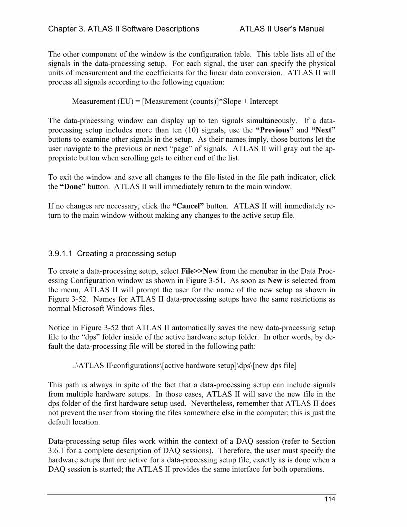
Chapter 3. ATLAS II Software Descriptions ATLAS II Users Manual
114
The other component of the window is the configuration table. This table lists all of the signals in the data-processing setup. For each signal, the user can specify the physical units of measurement and the coefficients for the linear data conversion. ATLAS II will process all signals according to the following equation:
Measurement (EU) = [Measurement (counts)]*Slope + Intercept
The data-processing window can display up to ten signals simultaneously. If a data-processing setup includes more than ten (10) signals, use the Previous and Next buttons to examine other signals in the setup. As their names imply, those buttons let the user navigate to the previous or next page of signals. ATLAS II will gray out the ap-propriate button when scrolling gets to either end of the list.
To exit the window and save all changes to the file listed in the file path indicator, click the Done button. ATLAS II will immediately return to the main window.
If no changes are necessary, click the Cancel button. ATLAS II will immediately re-turn to the main window without making any changes to the active setup file.
3.9.1.1 Creating a processing setup
To create a data-processing setup, select File>>New from the menubar in the Data Proc-essing Configuration window as shown in Figure 3-51. As soon as New is selected from the menu, ATLAS II will prompt the user for the name of the new setup as shown in Figure 3-52. Names for ATLAS II data-processing setups have the same restrictions as normal Microsoft Windows files.
Notice in Figure 3-52 that ATLAS II automatically saves the new data-processing setup file to the dps folder inside of the active hardware setup folder. In other words, by de-fault the data-processing file will be stored in the following path:
..\ATLAS II\configurations\[active hardware setup]\dps\[new dps file]
This path is always in spite of the fact that a data-processing setup can include signals from multiple hardware setups. In those cases, ATLAS II will save the new file in the dps folder of the first hardware setup used. Nevertheless, remember that ATLAS II does not prevent the user from storing the files somewhere else in the computer; this is just the default location.
Data-processing setup files work within the context of a DAQ session (refer to Section 3.6.1 for a complete description of DAQ sessions). Therefore, the user must specify the hardware setups that are active for a data-processing setup file, exactly as is done when a DAQ session is started; the ATLAS II provides the same interface for both operations.
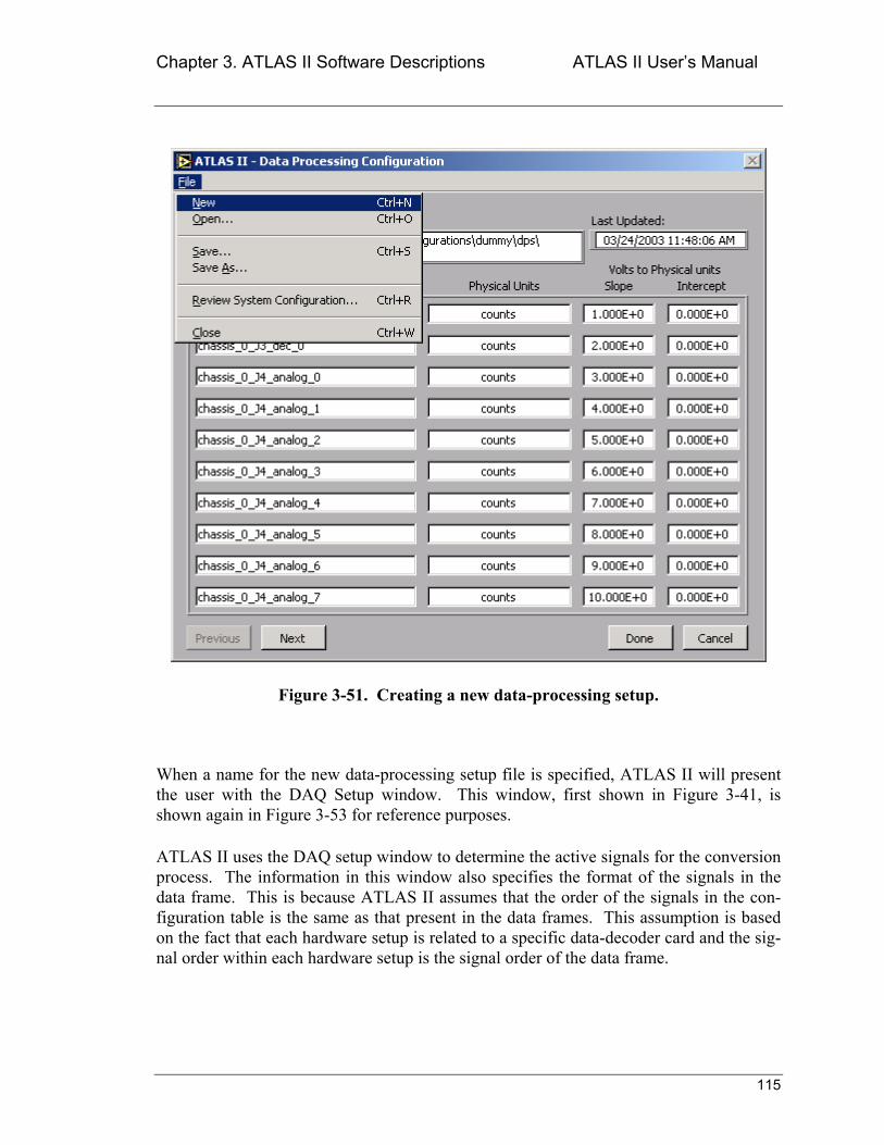
Chapter 3. ATLAS II Software Descriptions ATLAS II Users Manual
115
Figure 3-51. Creating a new data-processing setup.
When a name for the new data-processing setup file is specified, ATLAS II will present the user with the DAQ Setup window. This window, first shown in Figure 3-41, is shown again in Figure 3-53 for reference purposes.
ATLAS II uses the DAQ setup window to determine the active signals for the conversion process. The information in this window also specifies the format of the signals in the data frame. This is because ATLAS II assumes that the order of the signals in the con-figuration table is the same as that present in the data frames. This assumption is based on the fact that each hardware setup is related to a specific data-decoder card and the sig-nal order within each hardware setup is the signal order of the data frame.
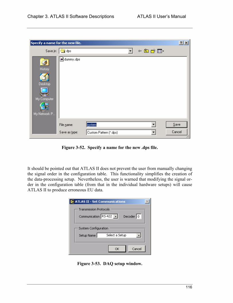
Chapter 3. ATLAS II Software Descriptions ATLAS II Users Manual
116
Figure 3-52. Specify a name for the new .dps file.
It should be pointed out that ATLAS II does not prevent the user from manually changing the signal order in the configuration table. This functionality simplifies the creation of the data-processing setup. Nevertheless, the user is warned that modifying the signal or-der in the configuration table (from that in the individual hardware setups) will cause ATLAS II to produce erroneous EU data.
Figure 3-53. DAQ setup window.
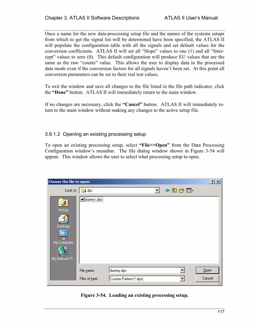
Chapter 3. ATLAS II Software Descriptions ATLAS II Users Manual
117
Once a name for the new data-processing setup file and the names of the systems setups from which to get the signal list will be determined have been specified, the ATLAS II will populate the configuration table with all the signals and set default values for the conversion coefficients. ATLAS II will set all Slope values to one (1) and all Inter-cept values to zero (0). This default configuration will produce EU values that are the same as the raw counts value. This allows the user to display data in the processed data mode even if the conversion factors for all signals havent been set. At this point all conversion parameters can be set to their real test values.
To exit the window and save all changes to the file listed in the file path indicator, click the Done button. ATLAS II will immediately return to the main window.
If no changes are necessary, click the Cancel button. ATLAS II will immediately re-turn to the main window without making any changes to the active setup file.
3.9.1.2 Opening an existing processing setup
To open an existing processing setup, select File>>Open from the Data Processing Configuration windows menubar. The file dialog window shown in Figure 3-54 will appear. This window allows the user to select what processing setup to open.
Figure 3-54. Loading an existing processing setup.
Chapter 3. ATLAS II Software Descriptions ATLAS II Users Manual
118
Once a processing setup from the list has been selected, click the Open button and ATLAS II will load that setup and make it the active processing setup. If no new file is needed, click the Cancel button and ATLAS II will return to the Data Processing Con-figuration window without no changes to the active processing setup.
3.9.1.3 Saving a processing setup
To save a processing setup, select File>>Save from the Data Processing Configuration windows menubar. No windows will appear as part of the save procedure. Instead, just look at the Last Updated indicator in the right side of the main window. ATLAS II updates this indicator every time the active processing setup is saved.
When the Data Configuration window is closed by clicking the Done button, ATLAS II will automatically perform a save-setup operation. This is done to make sure changes to the configuration are always detected.
3.9.1.4 Using an existing processing setup as a template
Sometimes during testing, changes to the active processing setups configuration may need to be made in order to experiment with different configurations. In those situations, keeping the original setup configuration intact may be useful so the system can revert to it in the case that the new configuration doesnt work. For this purpose, ATLAS II offers the save as operation.
When the File>>Save As option is selected from the Data Processing Configuration windows menubar, the file dialog window in Figure 3-55 will appear.
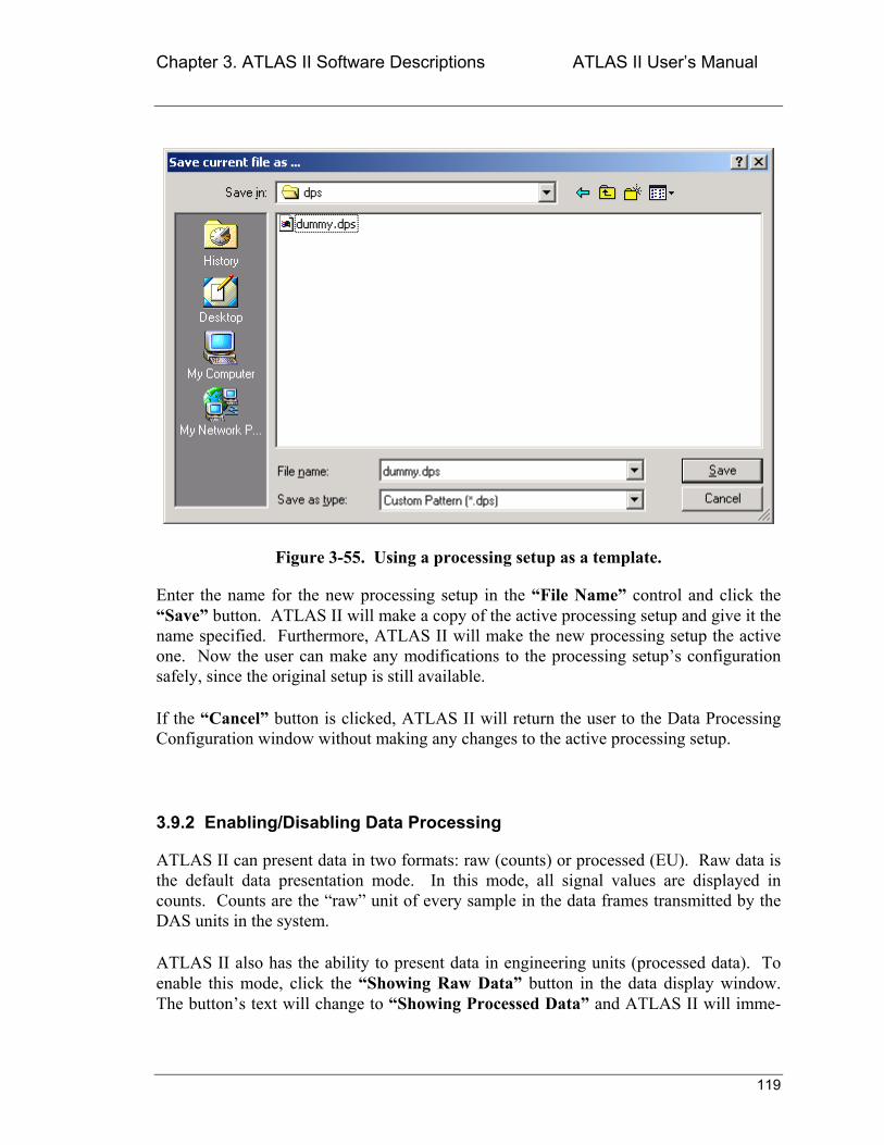
Chapter 3. ATLAS II Software Descriptions ATLAS II Users Manual
119
Figure 3-55. Using a processing setup as a template.
Enter the name for the new processing setup in the File Name control and click the Save button. ATLAS II will make a copy of the active processing setup and give it the name specified. Furthermore, ATLAS II will make the new processing setup the active one. Now the user can make any modifications to the processing setups configuration safely, since the original setup is still available.
If the Cancel button is clicked, ATLAS II will return the user to the Data Processing Configuration window without making any changes to the active processing setup.
3.9.2 Enabling/Disabling Data Processing
ATLAS II can present data in two formats: raw (counts) or processed (EU). Raw data is the default data presentation mode. In this mode, all signal values are displayed in counts. Counts are the raw unit of every sample in the data frames transmitted by the DAS units in the system.
ATLAS II also has the ability to present data in engineering units (processed data). To enable this mode, click the Showing Raw Data button in the data display window. The buttons text will change to Showing Processed Data and ATLAS II will imme-
Chapter 3. ATLAS II Software Descriptions ATLAS II Users Manual
120
diately switch to displaying data in engineering units. Beware that ATLAS II ability to display EU data is dependent on the user setting up a data-processing configuration file.
When the presentation of EU data is enabled, ATLAS II will try to convert the incoming raw data to EU data using the active data-processing configuration file. If no configura-tion file has been loaded or the files signals do not match the currently active setup, the results of the data conversion will not be correct. In the best case, ATLAS II will display raw data instead of EU data. In the worst case, ATLAS II will display a value of zero for a signal for which there is no entry in the data-processing configuration file.
To disable data processing, click the Showing Processed Data button in the data dis-play window. The buttons text will change to Showing Raw Data and ATLAS II will immediately switch to displaying data in counts.
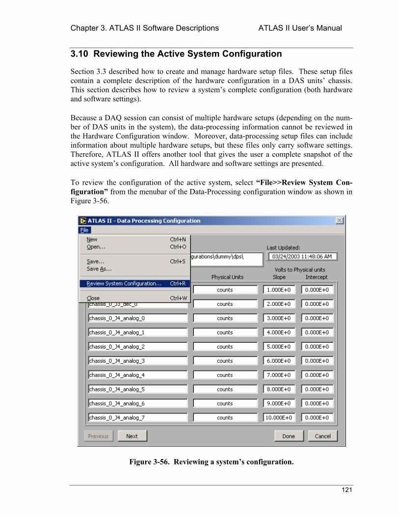
Chapter 3. ATLAS II Software Descriptions ATLAS II Users Manual
121
3.10 Reviewing the Active System Configuration
Section 3.3 described how to create and manage hardware setup files. These setup files contain a complete description of the hardware configuration in a DAS units chassis. This section describes how to review a systems complete configuration (both hardware and software settings).
Because a DAQ session can consist of multiple hardware setups (depending on the num-ber of DAS units in the system), the data-processing information cannot be reviewed in the Hardware Configuration window. Moreover, data-processing setup files can include information about multiple hardware setups, but these files only carry software settings. Therefore, ATLAS II offers another tool that gives the user a complete snapshot of the active systems configuration. All hardware and software settings are presented.
To review the configuration of the active system, select File>>Review System Con-figuration from the menubar of the Data-Processing configuration window as shown in Figure 3-56.
Figure 3-56. Reviewing a systems configuration.
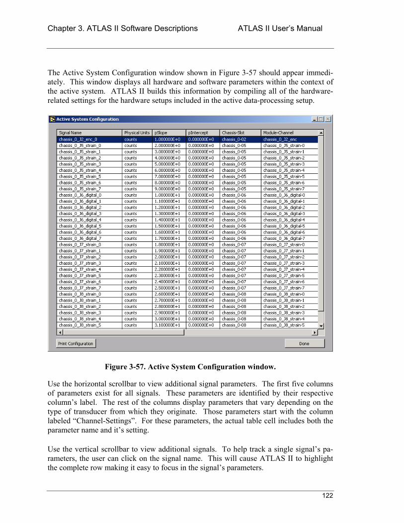
Chapter 3. ATLAS II Software Descriptions ATLAS II Users Manual
122
The Active System Configuration window shown in Figure 3-57 should appear immedi-ately. This window displays all hardware and software parameters within the context of the active system. ATLAS II builds this information by compiling all of the hardware-related settings for the hardware setups included in the active data-processing setup.
Figure 3-57. Active System Configuration window.
Use the horizontal scrollbar to view additional signal parameters. The first five columns of parameters exist for all signals. These parameters are identified by their respective columns label. The rest of the columns display parameters that vary depending on the type of transducer from which they originate. Those parameters start with the column labeled Channel-Settings. For these parameters, the actual table cell includes both the parameter name and its setting.
Use the vertical scrollbar to view additional signals. To help track a single signals pa-rameters, the user can click on the signal name. This will cause ATLAS II to highlight the complete row making it easy to focus in the signals parameters.
Chapter 3. ATLAS II Software Descriptions ATLAS II Users Manual
123
As shown in Figure 3-57, the Active System Configuration window has an option to pro-duce a hardcopy of the contents of the window. When the Print Configuration button is pressed, ATLAS II will send a printer-friendly version of the table to the default printer. Please, remember that it may take Windows several seconds to process the print request.
To exit the Active System Configuration window, click the Done button. ATLAS II will return to the Data Processing Configuration window.
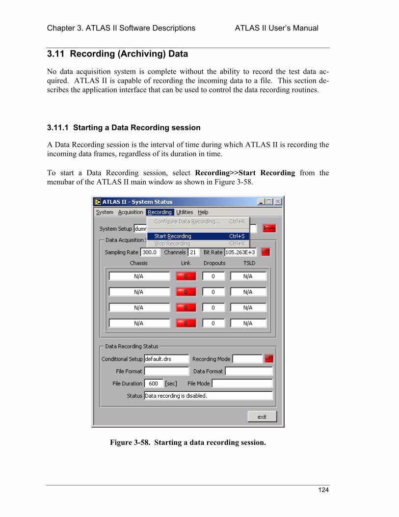
Chapter 3. ATLAS II Software Descriptions ATLAS II Users Manual
124
3.11 Recording (Archiving) Data
No data acquisition system is complete without the ability to record the test data ac-quired. ATLAS II is capable of recording the incoming data to a file. This section de-scribes the application interface that can be used to control the data recording routines.
3.11.1 Starting a Data Recording session
A Data Recording session is the interval of time during which ATLAS II is recording the incoming data frames, regardless of its duration in time.
To start a Data Recording session, select Recording>>Start Recording from the menubar of the ATLAS II main window as shown in Figure 3-58.
Figure 3-58. Starting a data recording session.
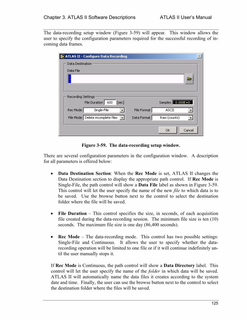
Chapter 3. ATLAS II Software Descriptions ATLAS II Users Manual
125
The data-recording setup window (Figure 3-59) will appear. This window allows the user to specify the configuration parameters required for the successful recording of in-coming data frames.
Figure 3-59. The data-recording setup window.
There are several configuration parameters in the configuration window. A description for all parameters is offered below:
• Data Destination Section: When the Rec Mode is set, ATLAS II changes the Data Destination section to display the appropriate path control. If Rec Mode is Single-File, the path control will show a Data File label as shown in Figure 3-59. This control will let the user specify the name of the new file to which data is to be saved. Use the browse button next to the control to select the destination folder where the file will be saved.
• File Duration This control specifies the size, in seconds, of each acquisition file created during the data-recording session. The minimum file size is ten (10) seconds. The maximum file size is one day (86,400 seconds).
• Rec Mode The data-recording mode. This control has two possible settings: Single-File and Continuous. It allows the user to specify whether the data-recording operation will be limited to one file or if it will continue indefinitely un-til the user manually stops it.
If Rec Mode is Continuous, the path control will show a Data Directory label. This control will let the user specify the name of the folder in which data will be saved. ATLAS II will automatically name the data files it creates according to the system date and time. Finally, the user can use the browse button next to the control to select the destination folder where the files will be saved.
Chapter 3. ATLAS II Software Descriptions ATLAS II Users Manual
126
• File Mode Controls what happens when the data-recording session is termi-nated. In the current software revision it has only one possible value: Delete in-complete files. This means that when the user commands ATLAS II to stop data recording, ATLAS II must stop data recording immediately and delete any data files that didnt accumulate the data samples specified in File Duration.
• Samples This indicator (no data input allowed) displays the size of the acquisi-tion file in samples. ATLAS II will calculate this number based on the value of File Duration and the systems sampling rate. It is displayed to give the user an idea of the space requirements of the recording operation.
• File Format Controls how ATLAS II stores sampled values in the data file. It has three possible settings:
o ASCII ATLAS II will store samples in text format. This format pro-vides the greatest compatibility with other applications (any word proces-sor or spreadsheet application can read the file). It also generates the largest data files.
o Zip Same as ASCII mode. However, once ATLAS II completes a data file, it will create a compressed (.zip) file that includes both the data file and its associated header file. This file format is the recommended format as it maintains data compatibility without sacrificing storage. The format of the compressed file is the industry-standard ZIP format.
o Binary ATLAS II will store samples in binary format. This format gen-erates the smallest data files at the expense of data compatibility. Only ATLAS II will be capable of reading data files generated in this format.
• Data Format Specifies the type of data samples to be stored. ATLAS II will generate data files according to this setting regardless of the data display mode during the data-recording session. It has two possible settings:
o Raw (counts) Samples will be stored in their original (counts) format.
o Processed (EU) ATLAS II will process all signals according to the ac-tive data-processing setup file and store the resulting EU values in the data file.
Make sure the correct data-processing setup file is loaded before starting a data-recording session that uses the Proc-essed (EU) format. If the wrong file is selected, the data will not be valid.
NOTE
Chapter 3. ATLAS II Software Descriptions ATLAS II Users Manual
127
3.11.2 Stopping a Data Recording session
As soon as a data-recording session is started, ATLAS II updates the Recording menu in the main window to reflect the new system state. Another change implemented is that the Start Recording menu option will be disabled and the Stop Recording option next to it will be enabled.
To stop a data-recording session, select Recording >>Stop Recording from the menubar of the ATLAS II main window. The data-recording activity LED in the main window should turn red immediately. In addition to the activity LED, the data-recording status information is reset and the main window will look as if the application had just started.
Stopping data recording does not stop data acquisition. The user can stop and re-start data recording at any time during a DAQ session. The only dependency between the two processes is that there must be an active DAQ session before data can be recorded. How-ever, even this restriction exists only in practical terms. The user can have an active data-recording session when there is no acquisition enabled, but it should not be per-formed as ATLAS II has no data to record.
Another way data recording can be stopped is by exiting the application. Before it termi-nates, ATLAS II will attempt to stop all on-going processes (acquisition, display, re-cording, etc.). However, this is not the best way to terminate these processes since they are in effect being aborted, but there will be no data corruption. Be aware that even in that case, the File Mode setting still controls how recording is going to be terminated.
3.11.3 Reading the Data Recording Status information
Figure 3-60 shows the ATLAS II main window during a typical data-recording session. In this section well discuss the significance of the data-recording status information pre-sented in the bottom section of the window.
The first status indicator to notice is the data-recording activity LED. This LED is simi-lar in function to the DAQ activity LED shown in the upper part of the window. Its color is red (with an OFF label) when data recording is disabled and green (with an ON label) when data recording is enabled.
The Conditional Setup indicator is not used by the current version of ATLAS II. It should always display the text default.drs as shown in Figure 3-60.
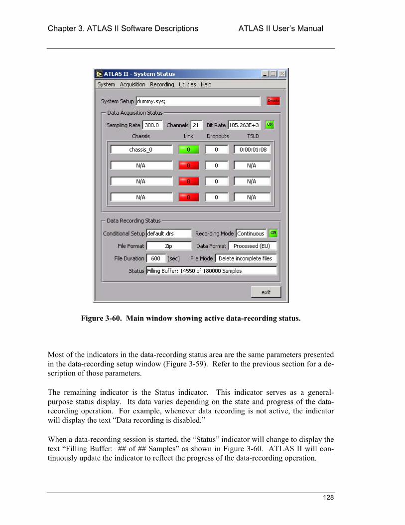
Chapter 3. ATLAS II Software Descriptions ATLAS II Users Manual
128
Figure 3-60. Main window showing active data-recording status.
Most of the indicators in the data-recording status area are the same parameters presented in the data-recording setup window (Figure 3-59). Refer to the previous section for a de-scription of those parameters.
The remaining indicator is the Status indicator. This indicator serves as a general-purpose status display. Its data varies depending on the state and progress of the data-recording operation. For example, whenever data recording is not active, the indicator will display the text Data recording is disabled.
When a data-recording session is started, the Status indicator will change to display the text Filling Buffer: ## of ## Samples as shown in Figure 3-60. ATLAS II will con-tinuously update the indicator to reflect the progress of the data-recording operation.
Chapter 3. ATLAS II Software Descriptions ATLAS II Users Manual
129
3.12 Using System Events (Automating ATLAS II)
To optimize its use and enhance user productivity, ATLAS II provides a tool that allows the user to automate its response to certain events. That tool is called System Events. This section describes the application interface used to control the system events engine included in ATLAS II.
Within the scope of ATLAS II, system events are a collection of stimulus and response (in this case event and response) combinations that give ATLAS II a sophisticated and automated way to behave under different test conditions. Examples of system events are:
• Highlight a particular signals plot whenever its value goes above a threshold.
• Start recording data when the value of signal X crosses a threshold.
• Send an e-mail to a staff member when the value of signal X crosses a threshold.
As illustrated by these examples, in each case there is an event (a signal crossing a threshold value) and a response (highlight plot, start recording, or send e-mail). ATLAS II allows the user to create lists of events that the application will monitor. Furthermore, the user can create a list of responses for each event. This way the user can create arbi-trarily complex and very specific patterns of behavior for ATLAS II.
The rest of this section will describe in detail how to define events and the response of ATLAS II to their occurrence.
3.12.1 Introduction to System Events
To configure system events, select System>>Configure System Events from the menubar of the ATLAS II main window as shown in Figure 3-61. The System Events Configuration window (Figure 3-62) will appear immediately.
The System Events Configuration window is divided into four main groups: menubar, active setup, events configuration, and responses configuration. The menubar is a normal Windows-application menubar. Its options will be discussed later on in this Chapter.
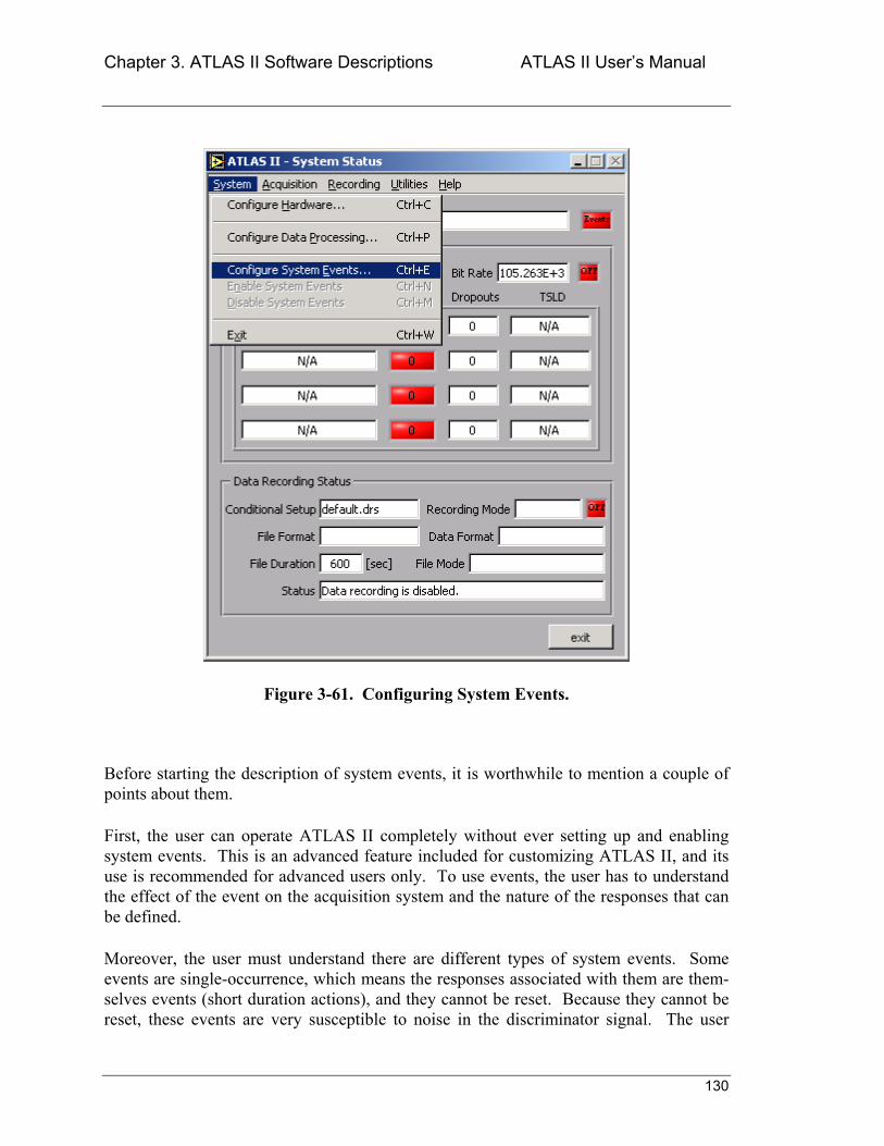
Chapter 3. ATLAS II Software Descriptions ATLAS II Users Manual
130
Figure 3-61. Configuring System Events.
Before starting the description of system events, it is worthwhile to mention a couple of points about them.
First, the user can operate ATLAS II completely without ever setting up and enabling system events. This is an advanced feature included for customizing ATLAS II, and its use is recommended for advanced users only. To use events, the user has to understand the effect of the event on the acquisition system and the nature of the responses that can be defined.
Moreover, the user must understand there are different types of system events. Some events are single-occurrence, which means the responses associated with them are them-selves events (short duration actions), and they cannot be reset. Because they cannot be reset, these events are very susceptible to noise in the discriminator signal. The user
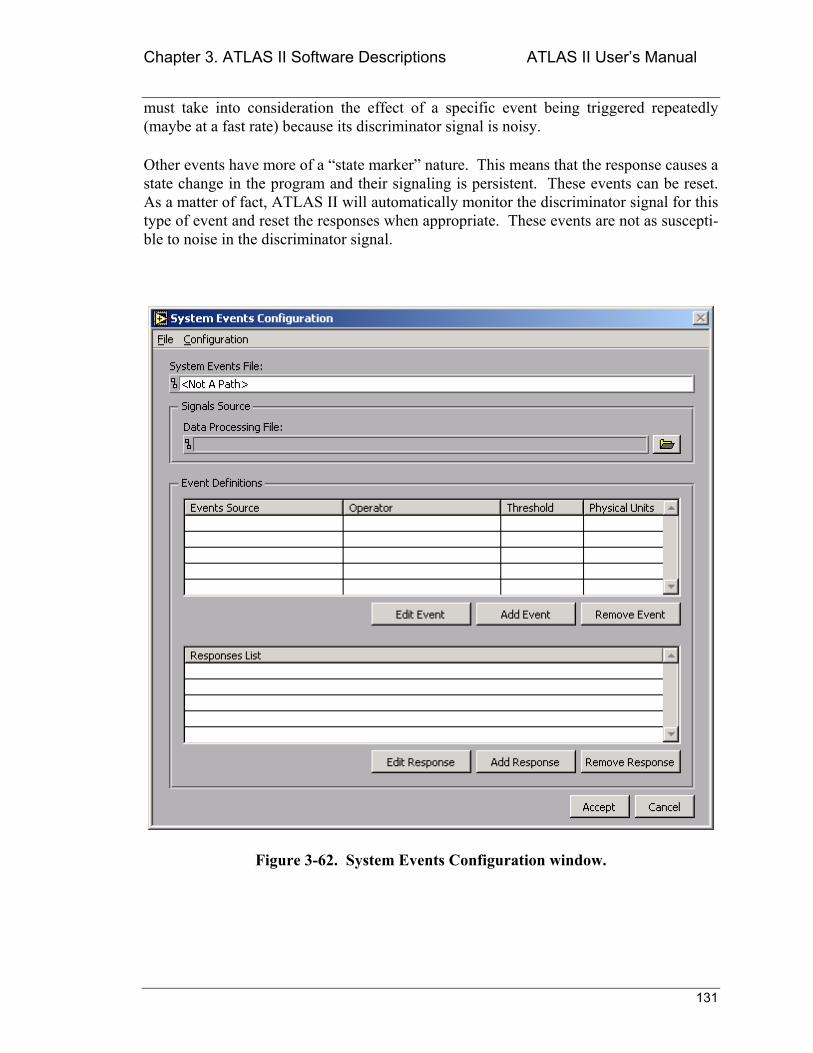
Chapter 3. ATLAS II Software Descriptions ATLAS II Users Manual
131
must take into consideration the effect of a specific event being triggered repeatedly (maybe at a fast rate) because its discriminator signal is noisy.
Other events have more of a state marker nature. This means that the response causes a state change in the program and their signaling is persistent. These events can be reset. As a matter of fact, ATLAS II will automatically monitor the discriminator signal for this type of event and reset the responses when appropriate. These events are not as suscepti-ble to noise in the discriminator signal.
Figure 3-62. System Events Configuration window.
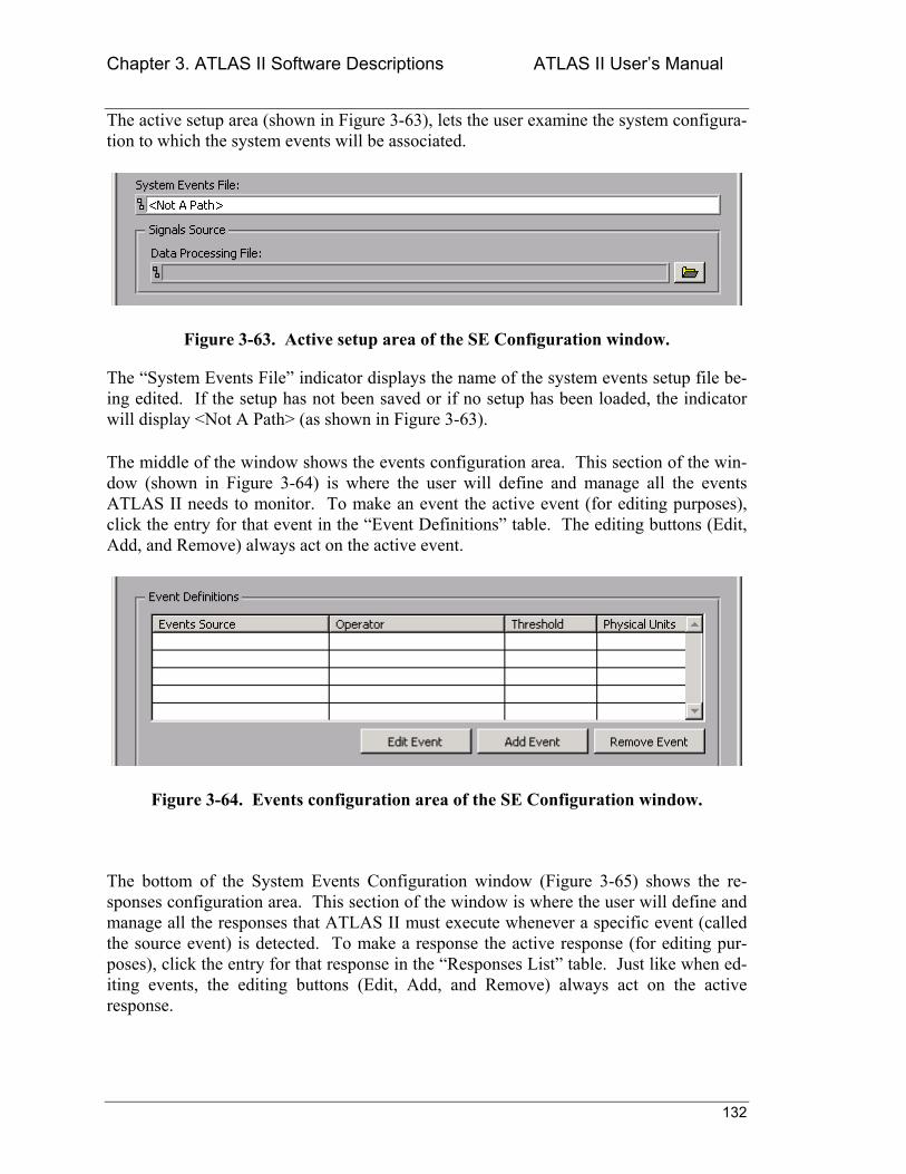
Chapter 3. ATLAS II Software Descriptions ATLAS II Users Manual
132
The active setup area (shown in Figure 3-63), lets the user examine the system configura-tion to which the system events will be associated.
Figure 3-63. Active setup area of the SE Configuration window.
The System Events File indicator displays the name of the system events setup file be-ing edited. If the setup has not been saved or if no setup has been loaded, the indicator will display <Not A Path> (as shown in Figure 3-63).
The middle of the window shows the events configuration area. This section of the win-dow (shown in Figure 3-64) is where the user will define and manage all the events ATLAS II needs to monitor. To make an event the active event (for editing purposes), click the entry for that event in the Event Definitions table. The editing buttons (Edit, Add, and Remove) always act on the active event.
Figure 3-64. Events configuration area of the SE Configuration window.
The bottom of the System Events Configuration window (Figure 3-65) shows the re-sponses configuration area. This section of the window is where the user will define and manage all the responses that ATLAS II must execute whenever a specific event (called the source event) is detected. To make a response the active response (for editing pur-poses), click the entry for that response in the Responses List table. Just like when ed-iting events, the editing buttons (Edit, Add, and Remove) always act on the active response.
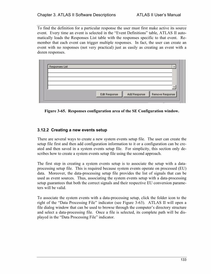
Chapter 3. ATLAS II Software Descriptions ATLAS II Users Manual
133
To find the definition for a particular response the user must first make active its source event. Every time an event is selected in the Event Definitions table, ATLAS II auto-matically loads the Responses List table with the responses specific to that event. Re-member that each event can trigger multiple responses. In fact, the user can create an event with no responses (not very practical) just as easily as creating an event with a dozen responses.
Figure 3-65. Responses configuration area of the SE Configuration window.
3.12.2 Creating a new events setup
There are several ways to create a new system events setup file. The user can create the setup file first and then add configuration information to it or a configuration can be cre-ated and then saved in a system events setup file. For simplicity, this section only de-scribes how to create a system events setup file using the second approach.
The first step in creating a system events setup is to associate the setup with a data-processing setup file. This is required because system events operate on processed (EU) data. Moreover, the data-processing setup file provides the list of signals that can be used as event sources. Thus, associating the system events setup with a data-processing setup guarantees that both the correct signals and their respective EU conversion parame-ters will be valid.
To associate the system events with a data-processing setup, click the folder icon to the right of the Data Processing File indicator (see Figure 3-63). ATLAS II will open a file dialog window that can be used to browse through the computers directory structure and select a data-processing file. Once a file is selected, its complete path will be dis-played in the Data Processing File indicator.
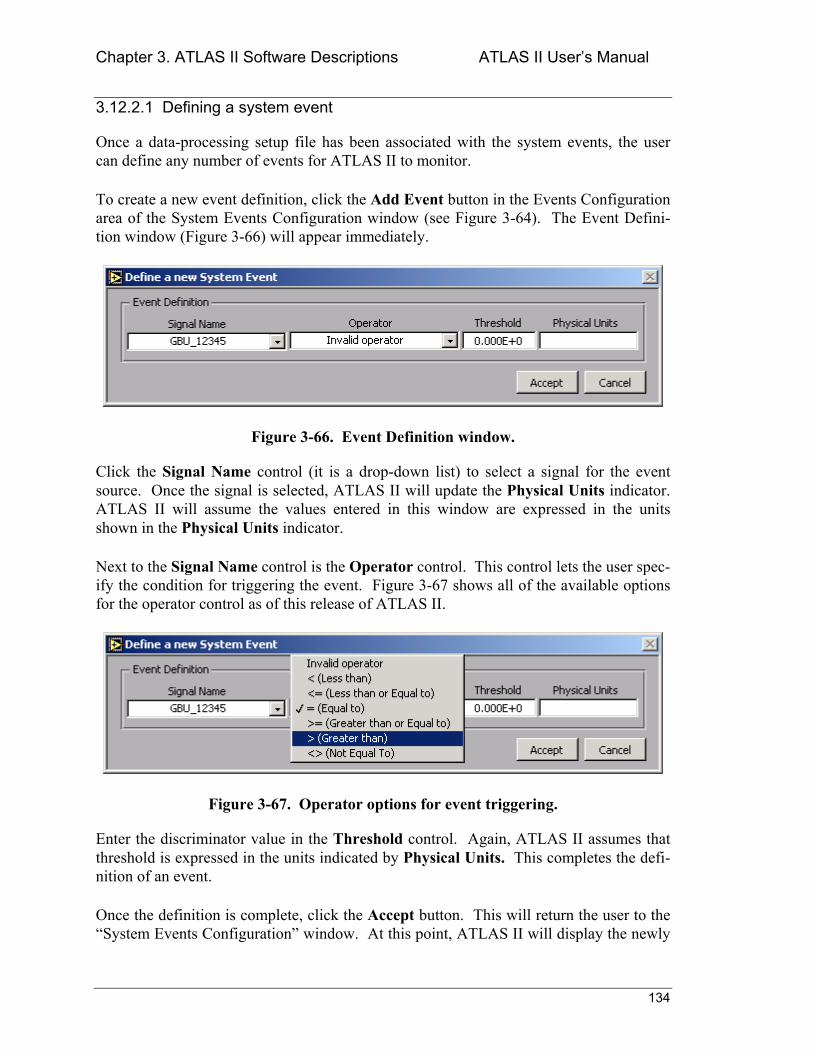
Chapter 3. ATLAS II Software Descriptions ATLAS II Users Manual
134
3.12.2.1 Defining a system event
Once a data-processing setup file has been associated with the system events, the user can define any number of events for ATLAS II to monitor.
To create a new event definition, click the Add Event button in the Events Configuration area of the System Events Configuration window (see Figure 3-64). The Event Defini-tion window (Figure 3-66) will appear immediately.
Figure 3-66. Event Definition window.
Click the Signal Name control (it is a drop-down list) to select a signal for the event source. Once the signal is selected, ATLAS II will update the Physical Units indicator. ATLAS II will assume the values entered in this window are expressed in the units shown in the Physical Units indicator.
Next to the Signal Name control is the Operator control. This control lets the user spec-ify the condition for triggering the event. Figure 3-67 shows all of the available options for the operator control as of this release of ATLAS II.
Figure 3-67. Operator options for event triggering.
Enter the discriminator value in the Threshold control. Again, ATLAS II assumes that threshold is expressed in the units indicated by Physical Units. This completes the defi-nition of an event.
Once the definition is complete, click the Accept button. This will return the user to the System Events Configuration window. At this point, ATLAS II will display the newly
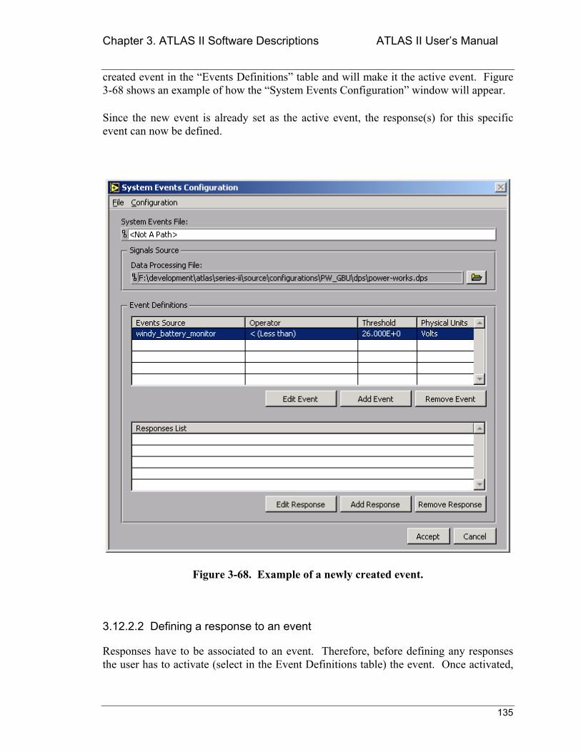
Chapter 3. ATLAS II Software Descriptions ATLAS II Users Manual
135
created event in the Events Definitions table and will make it the active event. Figure 3-68 shows an example of how the System Events Configuration window will appear.
Since the new event is already set as the active event, the response(s) for this specific event can now be defined.
Figure 3-68. Example of a newly created event.
3.12.2.2 Defining a response to an event
Responses have to be associated to an event. Therefore, before defining any responses the user has to activate (select in the Event Definitions table) the event. Once activated,
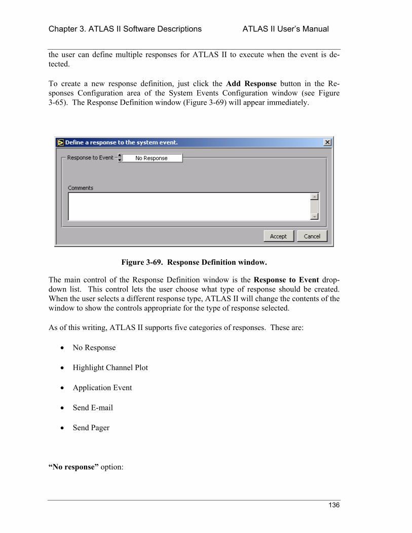
Chapter 3. ATLAS II Software Descriptions ATLAS II Users Manual
136
the user can define multiple responses for ATLAS II to execute when the event is de-tected.
To create a new response definition, just click the Add Response button in the Re-sponses Configuration area of the System Events Configuration window (see Figure 3-65). The Response Definition window (Figure 3-69) will appear immediately.
Figure 3-69. Response Definition window.
The main control of the Response Definition window is the Response to Event drop-down list. This control lets the user choose what type of response should be created. When the user selects a different response type, ATLAS II will change the contents of the window to show the controls appropriate for the type of response selected.
As of this writing, ATLAS II supports five categories of responses. These are:
• No Response
• Highlight Channel Plot
• Application Event
• Send E-mail
• Send Pager
No response option:
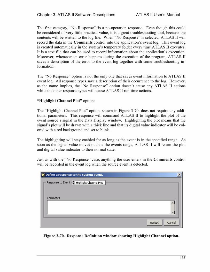
Chapter 3. ATLAS II Software Descriptions ATLAS II Users Manual
137
The first category, No Response, is a no-operation response. Even though this could be considered of very little practical value, it is a great troubleshooting tool, because the contents will be written to the log file. When No Response is selected, ATLAS II will record the data in the Comments control into the applications event log. This event log is created automatically in the systems temporary folder every time ATLAS II executes. It is a text file that can be used to record information about the applications execution. Moreover, whenever an error happens during the execution of the program, ATLAS II saves a description of the error to the event log together with some troubleshooting in-formation.
The No Response option is not the only one that saves event information to ATLAS II event log. All response types save a description of their occurrence to the log. However, as the name implies, the No Response option doesnt cause any ATLAS II actions while the other response types will cause ATLAS II run-time actions.
Highlight Channel Plot option:
The Highlight Channel Plot option, shown in Figure 3-70, does not require any addi-tional parameters. This response will command ATLAS II to highlight the plot of the event sources signal in the Data Display window. Highlighting the plot means that the signals plot will be drawn with a thick line and that its digital value indicator will be col-ored with a red background and set to blink.
The highlighting will stay enabled for as long as the event is in the specified range. As soon as the signal value moves outside the events range, ATLAS II will return the plot and digital value indicator to their normal state.
Just as with the No Response case, anything the user enters in the Comments control will be recorded in the event log when the source event is detected.
Figure 3-70. Response Definition window showing Highlight Channel option.
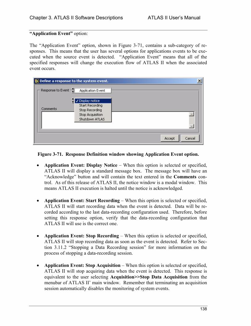
Chapter 3. ATLAS II Software Descriptions ATLAS II Users Manual
138
Application Event option:
The Application Event option, shown in Figure 3-71, contains a sub-category of re-sponses. This means that the user has several options for applications events to be exe-cuted when the source event is detected. Application Event means that all of the specified responses will change the execution flow of ATLAS II when the associated event occurs.
Figure 3-71. Response Definition window showing Application Event option.
• Application Event: Display Notice When this option is selected or specified, ATLAS II will display a standard message box. The message box will have an Acknowledge button and will contain the text entered in the Comments con-trol. As of this release of ATLAS II, the notice window is a modal window. This means ATLAS II execution is halted until the notice is acknowledged.
• Application Event: Start Recording When this option is selected or specified, ATLAS II will start recording data when the event is detected. Data will be re-corded according to the last data-recording configuration used. Therefore, before setting this response option, verify that the data-recording configuration that ATLAS II will use is the correct one.
• Application Event: Stop Recording When this option is selected or specified, ATLAS II will stop recording data as soon as the event is detected. Refer to Sec-tion 3.11.2 Stopping a Data Recording session for more information on the process of stopping a data-recording session.
• Application Event: Stop Acquisition When this option is selected or specified, ATLAS II will stop acquiring data when the event is detected. This response is equivalent to the user selecting Acquisition>>Stop Data Acquisition from the menubar of ATLAS II main window. Remember that terminating an acquisition session automatically disables the monitoring of system events.
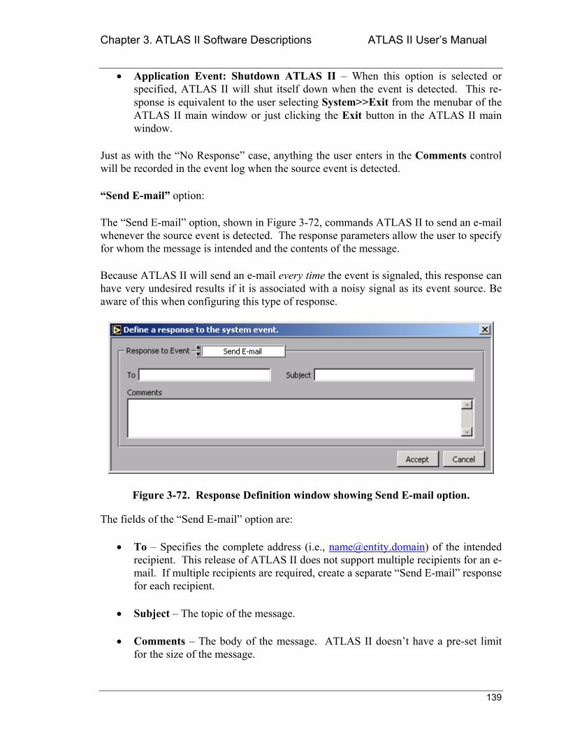
Chapter 3. ATLAS II Software Descriptions ATLAS II Users Manual
139
• Application Event: Shutdown ATLAS II When this option is selected or specified, ATLAS II will shut itself down when the event is detected. This re-sponse is equivalent to the user selecting System>>Exit from the menubar of the ATLAS II main window or just clicking the Exit button in the ATLAS II main window.
Just as with the No Response case, anything the user enters in the Comments control will be recorded in the event log when the source event is detected.
Send E-mail option:
The Send E-mail option, shown in Figure 3-72, commands ATLAS II to send an e-mail whenever the source event is detected. The response parameters allow the user to specify for whom the message is intended and the contents of the message.
Because ATLAS II will send an e-mail every time the event is signaled, this response can have very undesired results if it is associated with a noisy signal as its event source. Be aware of this when configuring this type of response.
Figure 3-72. Response Definition window showing Send E-mail option.
The fields of the Send E-mail option are:
• To Specifies the complete address (i.e., [email protected]) of the intended recipient. This release of ATLAS II does not support multiple recipients for an e-mail. If multiple recipients are required, create a separate Send E-mail response for each recipient.
• Subject The topic of the message.
• Comments The body of the message. ATLAS II doesnt have a pre-set limit for the size of the message.
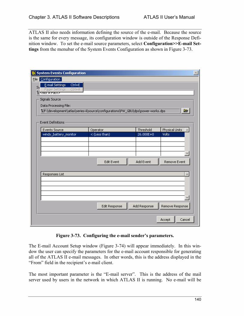
Chapter 3. ATLAS II Software Descriptions ATLAS II Users Manual
140
ATLAS II also needs information defining the source of the e-mail. Because the source is the same for every message, its configuration window is outside of the Response Defi-nition window. To set the e-mail source parameters, select Configuration>>E-mail Set-tings from the menubar of the System Events Configuration as shown in Figure 3-73.
Figure 3-73. Configuring the e-mail senders parameters.
The E-mail Account Setup window (Figure 3-74) will appear immediately. In this win-dow the user can specify the parameters for the e-mail account responsible for generating all of the ATLAS II e-mail messages. In other words, this is the address displayed in the From field in the recipients e-mail client.
The most important parameter is the E-mail server. This is the address of the mail server used by users in the network in which ATLAS II is running. No e-mail will be
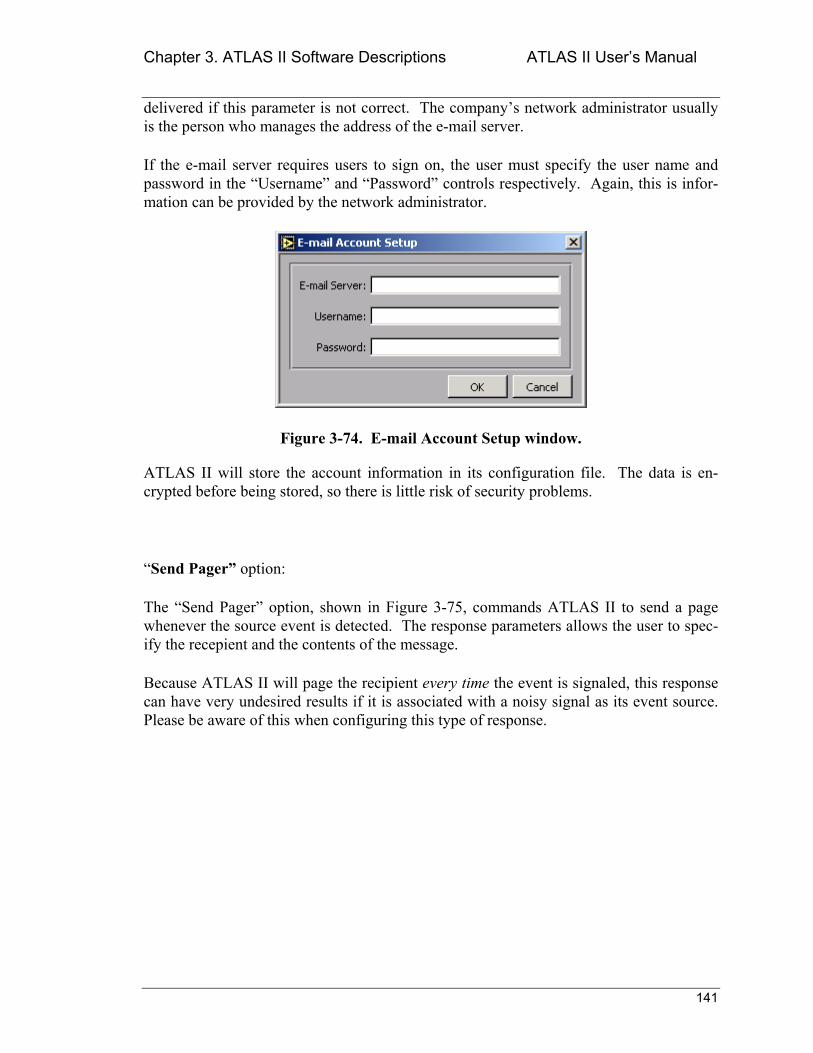
Chapter 3. ATLAS II Software Descriptions ATLAS II Users Manual
141
delivered if this parameter is not correct. The companys network administrator usually is the person who manages the address of the e-mail server.
If the e-mail server requires users to sign on, the user must specify the user name and password in the Username and Password controls respectively. Again, this is infor-mation can be provided by the network administrator.
Figure 3-74. E-mail Account Setup window.
ATLAS II will store the account information in its configuration file. The data is en-crypted before being stored, so there is little risk of security problems.
Send Pager option:
The Send Pager option, shown in Figure 3-75, commands ATLAS II to send a page whenever the source event is detected. The response parameters allows the user to spec-ify the recepient and the contents of the message.
Because ATLAS II will page the recipient every time the event is signaled, this response can have very undesired results if it is associated with a noisy signal as its event source. Please be aware of this when configuring this type of response.
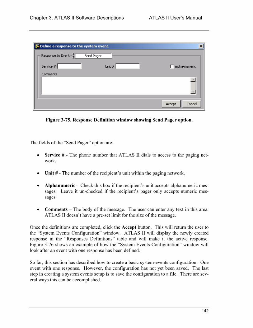
Chapter 3. ATLAS II Software Descriptions ATLAS II Users Manual
142
Figure 3-75. Response Definition window showing Send Pager option.
The fields of the Send Pager option are:
• Service # - The phone number that ATLAS II dials to access to the paging net-work.
• Unit # - The number of the recipients unit within the paging network.
• Alphanumeric Check this box if the recipients unit accepts alphanumeric mes-sages. Leave it un-checked if the recipients pager only accepts numeric mes-sages.
• Comments The body of the message. The user can enter any text in this area. ATLAS II doesnt have a pre-set limit for the size of the message.
Once the definitions are completed, click the Accept button. This will return the user to the System Events Configuration window. ATLAS II will display the newly created response in the Responses Definitions table and will make it the active response. Figure 3-76 shows an example of how the System Events Configuration window will look after an event with one response has been defined.
So far, this section has described how to create a basic system-events configuration: One event with one response. However, the configuration has not yet been saved. The last step in creating a system events setup is to save the configuration to a file. There are sev-eral ways this can be accomplished.
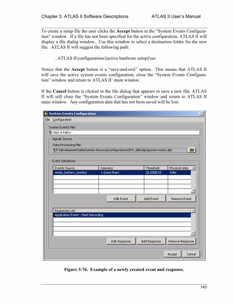
Chapter 3. ATLAS II Software Descriptions ATLAS II Users Manual
143
To create a setup file the user clicks the Accept button in the System Events Configura-tion window. If a file has not been specified for the active configuration, ATLAS II will display a file dialog window. Use this window to select a destination folder for the new file. ATLAS II will suggest the following path:
..ATLAS II\configurations\[active hardware setup]\ses
Notice that the Accept button is a save-and-exit option. This means that ATLAS II will save the active system events configuration, close the System Events Configura-tion window and return to ATLAS II main window.
If the Cancel button is clicked in the file dialog that appears to save a new file, ATLAS II will still close the System Events Configuration window and return to ATLAS II main window. Any configuration data that has not been saved will be lost.
Figure 3-76. Example of a newly created event and response.
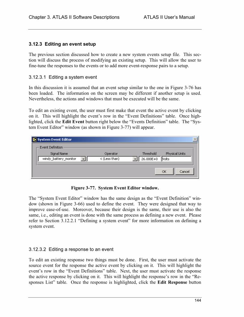
Chapter 3. ATLAS II Software Descriptions ATLAS II Users Manual
144
3.12.3 Editing an event setup
The previous section discussed how to create a new system events setup file. This sec-tion will discuss the process of modifying an existing setup. This will allow the user to fine-tune the responses to the events or to add more event-response pairs to a setup.
3.12.3.1 Editing a system event
In this discussion it is assumed that an event setup similar to the one in Figure 3-76 has been loaded. The information on the screen may be different if another setup is used. Nevertheless, the actions and windows that must be executed will be the same.
To edit an existing event, the user must first make that event the active event by clicking on it. This will highlight the events row in the Event Definitions table. Once high-lighted, click the Edit Event button right below the Events Definition table. The Sys-tem Event Editor window (as shown in Figure 3-77) will appear.
Figure 3-77. System Event Editor window.
The System Event Editor window has the same design as the Event Definition win-dow (shown in Figure 3-66) used to define the event. They were designed that way to improve ease-of-use. Moreover, because their design is the same, their use is also the same, i.e., editing an event is done with the same process as defining a new event. Please refer to Section 3.12.2.1 Defining a system event for more information on defining a system event.
3.12.3.2 Editing a response to an event
To edit an existing response two things must be done. First, the user must activate the source event for the response the active event by clicking on it. This will highlight the events row in the Event Definitions table. Next, the user must activate the response the active response by clicking on it. This will highlight the responses row in the Re-sponses List table. Once the response is highlighted, click the Edit Response button
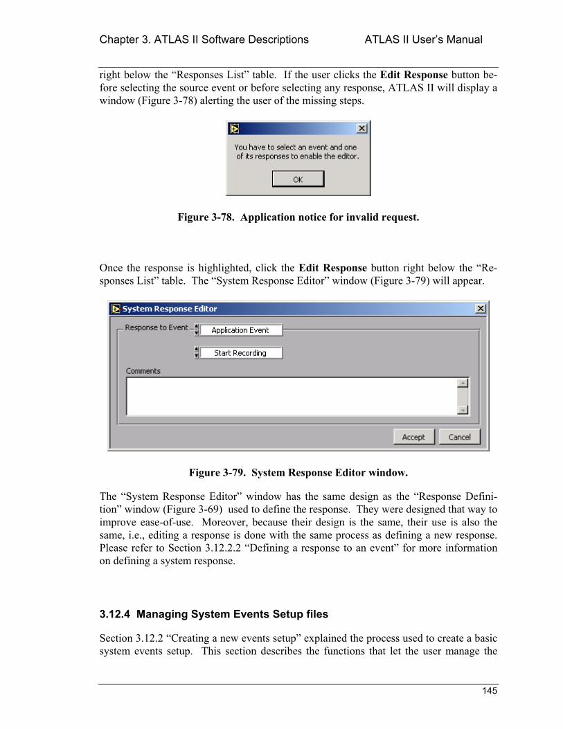
Chapter 3. ATLAS II Software Descriptions ATLAS II Users Manual
145
right below the Responses List table. If the user clicks the Edit Response button be-fore selecting the source event or before selecting any response, ATLAS II will display a window (Figure 3-78) alerting the user of the missing steps.
Figure 3-78. Application notice for invalid request.
Once the response is highlighted, click the Edit Response button right below the Re-sponses List table. The System Response Editor window (Figure 3-79) will appear.
Figure 3-79. System Response Editor window.
The System Response Editor window has the same design as the Response Defini-tion window (Figure 3-69) used to define the response. They were designed that way to improve ease-of-use. Moreover, because their design is the same, their use is also the same, i.e., editing a response is done with the same process as defining a new response. Please refer to Section 3.12.2.2 Defining a response to an event for more information on defining a system response.
3.12.4 Managing System Events Setup files
Section 3.12.2 Creating a new events setup explained the process used to create a basic system events setup. This section describes the functions that let the user manage the
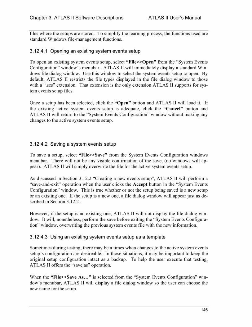
Chapter 3. ATLAS II Software Descriptions ATLAS II Users Manual
146
files where the setups are stored. To simplify the learning process, the functions used are standard Windows file-management functions.
3.12.4.1 Opening an existing system events setup
To open an existing system events setup, select File>>Open from the System Events Configuration windows menubar. ATLAS II will immediately display a standard Win-dows file dialog window. Use this window to select the system events setup to open. By default, ATLAS II restricts the file types displayed in the file dialog window to those with a .ses extension. That extension is the only extension ATLAS II supports for sys-tem events setup files.
Once a setup has been selected, click the Open button and ATLAS II will load it. If the existing active system events setup is adequate, click the Cancel button and ATLAS II will return to the System Events Configuration window without making any changes to the active system events setup.
3.12.4.2 Saving a system events setup
To save a setup, select File>>Save from the System Events Configuration windows menubar. There will not be any visible confirmation of the save, (no windows will ap-pear). ATLAS II will simply overwrite the file for the active system events setup.
As discussed in Section 3.12.2 Creating a new events setup, ATLAS II will perform a save-and-exit operation when the user clicks the Accept button in the System Events Configuration window. This is true whether or not the setup being saved is a new setup or an existing one. If the setup is a new one, a file dialog window will appear just as de-scribed in Section 3.12.2 .
However, if the setup is an existing one, ATLAS II will not display the file dialog win-dow. It will, nonetheless, perform the save before exiting the System Events Configura-tion window, overwriting the previous system events file with the new information.
3.12.4.3 Using an existing system events setup as a template
Sometimes during testing, there may be a times when changes to the active system events setups configuration are desireable. In those situations, it may be important to keep the original setup configuration intact as a backup. To help the user execute that testing, ATLAS II offers the save as operation.
When the File>>Save As is selected from the System Events Configuration win-dows menubar, ATLAS II will display a file dialog window so the user can choose the new name for the setup.
Chapter 3. ATLAS II Software Descriptions ATLAS II Users Manual
147
Enter the name for the new setup in the File name: control and click the Save but-ton. ATLAS II will make a copy of the active system events setup and give it the speci-fied name. Furthermore, ATLAS II will make the new setup the active one. Now modifications to the setups configuration can be safely made, knowing the original setup is still available in case it is needed.
If the Cancel button is clicked, ATLAS II will return the user to the System Events Configuration window without making any changes to the active system events setup.
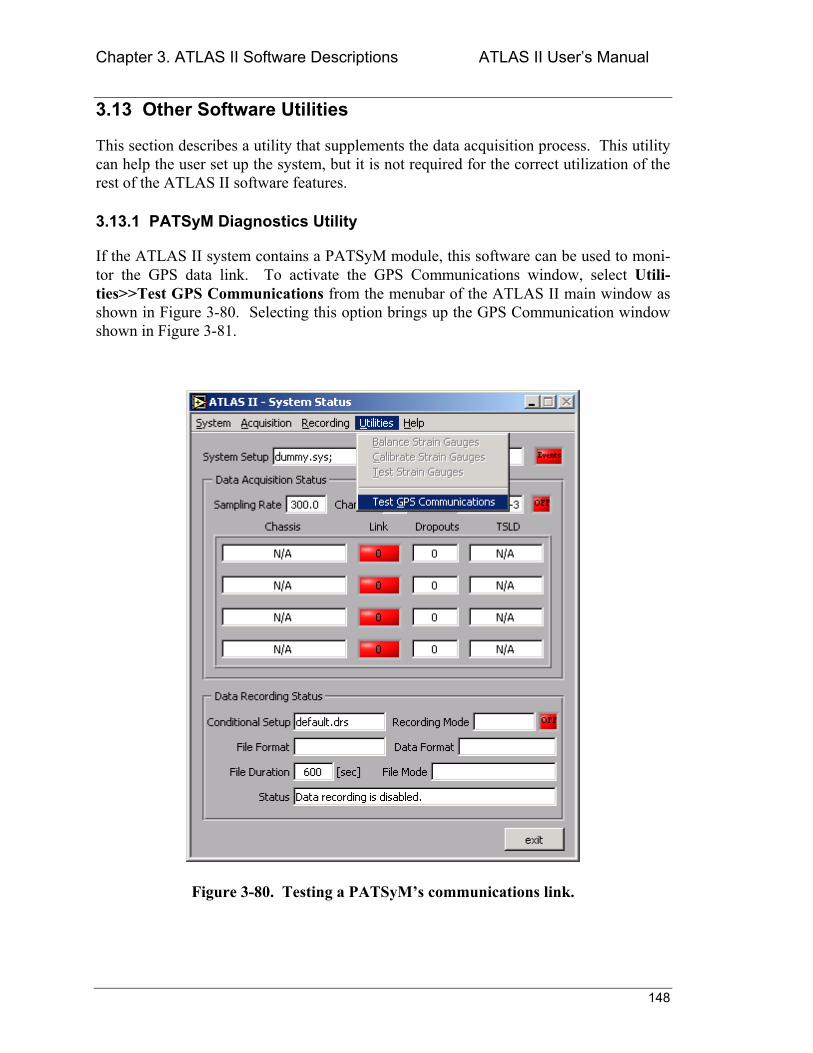
Chapter 3. ATLAS II Software Descriptions ATLAS II Users Manual
148
3.13 Other Software Utilities
This section describes a utility that supplements the data acquisition process. This utility can help the user set up the system, but it is not required for the correct utilization of the rest of the ATLAS II software features.
3.13.1 PATSyM Diagnostics Utility
If the ATLAS II system contains a PATSyM module, this software can be used to moni-tor the GPS data link. To activate the GPS Communications window, select Utili-ties>>Test GPS Communications from the menubar of the ATLAS II main window as shown in Figure 3-80. Selecting this option brings up the GPS Communication window shown in Figure 3-81.
Figure 3-80. Testing a PATSyMs communications link.
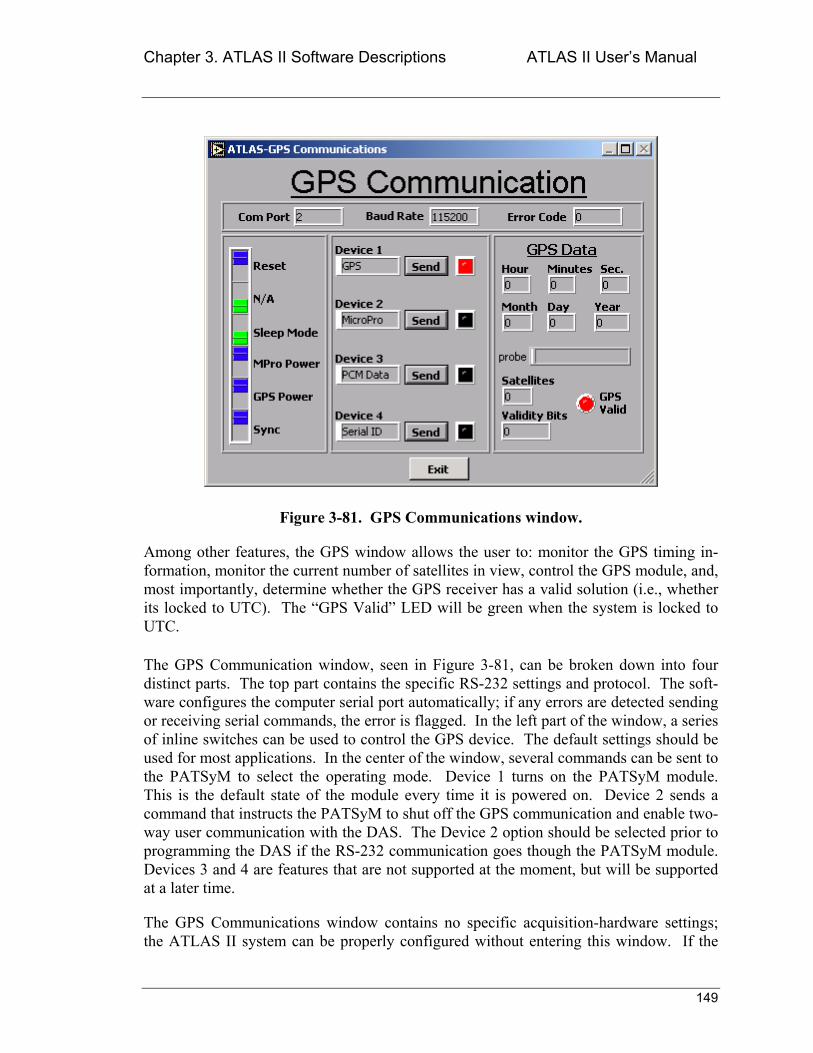
Chapter 3. ATLAS II Software Descriptions ATLAS II Users Manual
149
Figure 3-81. GPS Communications window.
Among other features, the GPS window allows the user to: monitor the GPS timing in-formation, monitor the current number of satellites in view, control the GPS module, and, most importantly, determine whether the GPS receiver has a valid solution (i.e., whether its locked to UTC). The GPS Valid LED will be green when the system is locked to UTC.
The GPS Communication window, seen in Figure 3-81, can be broken down into four distinct parts. The top part contains the specific RS-232 settings and protocol. The soft-ware configures the computer serial port automatically; if any errors are detected sending or receiving serial commands, the error is flagged. In the left part of the window, a series of inline switches can be used to control the GPS device. The default settings should be used for most applications. In the center of the window, several commands can be sent to the PATSyM to select the operating mode. Device 1 turns on the PATSyM module. This is the default state of the module every time it is powered on. Device 2 sends a command that instructs the PATSyM to shut off the GPS communication and enable two-way user communication with the DAS. The Device 2 option should be selected prior to programming the DAS if the RS-232 communication goes though the PATSyM module. Devices 3 and 4 are features that are not supported at the moment, but will be supported at a later time.
The GPS Communications window contains no specific acquisition-hardware settings; the ATLAS II system can be properly configured without entering this window. If the
Chapter 3. ATLAS II Software Descriptions ATLAS II Users Manual
150
ATLAS II system contains a PATSyM module and is wired as recommended in this document, this window must be accessed to turn off GPS data-transmission before a DAS chassis can be programmed.
Chapter 4. ATLAS II References ATLAS II Users Manual
151
Chapter 4. References Berg, D.E, Zayas, J.R.. 2001. Accurate GPS Time-Linked Data Acquisition System (ATLAS II) Users Manual. Sandia National Laboratories; Albuquer-que, NM-SAND2001-1289.
Berg, D.E., and Zayas, J.R. 2001. Accurate Time-Linked Acquisition System Field Deployment and Operational Experience, AIAA 2001-0038, Proceedings of the 2001 ASME Wind Energy Symposium, Reno, NV, January 811, 2001.
Berg, D.E., Rumsey, M.A., and Zayas, J.R. 2000. Hardware and Software Develop-ments for the Accurate Time-Linked Data Acquisition System, AIAA 2000-0052, Pro-ceedings of the 2000 ASME Wind Energy Symposium, Reno, NV, January 1013, 2000, pp. 306-316.
Robertson, P.J., Berg, D.E., Zayas, J.R., and Gass, K.L. 1999. Final Report and Docu-mentation for the GPS-10K70 Board Design. Sandia National Laboratories; Albuquer-que, NM.
Berg, D.E., Robertson, P., and Zayas, J. 1999. ATLAS II: A Small, Light Weight, Time-Synchronized Wind-Turbine Data Acquisition System. Presented at the 1999 ASME Wind Energy Symposium in Reno, NV, January 11-14, 1998. Sandia National Laborato-ries; Albuquerque, NM.
Berg, D.E., Rumsey, M., Robertson, P. 1998. Development of a Light-Weight, Wind-Turbine-Rotor-Based Data Acquisition System. Presented at 1998 ASME Wind Energy Symposium/36th AIAA Aerospace Sciences Meeting and Exhibit in Reno, NV, January 12-15, 1998. Sandia National Laboratories; Albuquerque, NM.
Berg, D.E., Robertson, P.J., and Ortiz, M.F. 1998. Development and Application of a Light-Weight, Wind-Turbine Rotor-Based Data Acquisition System. Presented at Wind-power 98, Bakersfield, CA, April 27-May 1, 1998. Sandia National Laboratories; Albu-querque, NM.
Berg, D.E., and Robertson, P.J. 1998. Precise Time Synchronization Data Acquisition with Remote Systems Proceedings of 1998 International Telemetering Conference, San Diego, CA, October 2629, 1998.
Nicolet Instrument Technologies, Inc. 1996. Nicolet MicroPro Remote Data Acquisition System Operation Manual, Version 1.40. P/N 269-923000. Madison, WI.
Zond Systems, Inc. 1994. Advanced Data-Acquisition System. Tehachapi, CA.

Chapter 4. ATLAS II References ATLAS II Users Manual
152
This page intentionally left blank.
Chapter 5. ATLAS II Technical Support ATLAS II Users Manual
153
Chapter 5. Technical Support ACRA Control, Inc., 44145 Airport View Drive Hollywood, MD 20636 John Kolb 301-373-9220 Sandia National Laboratories P.O. Box 5800 Albuquerque, NM 87185-0708 Jose Zayas 505-284-9446
Chapter 5. ATLAS II Technical Support ATLAS II Users Manual
154
This page intentionally left blank.

Appendix A: ATLAS II Lightning Protection ATLAS II Users Manual
A-1
Appendix A: Citel Protection Devices Specification Sheets
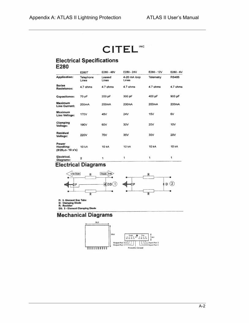
Appendix A: ATLAS II Lightning Protection ATLAS II Users Manual
A-2
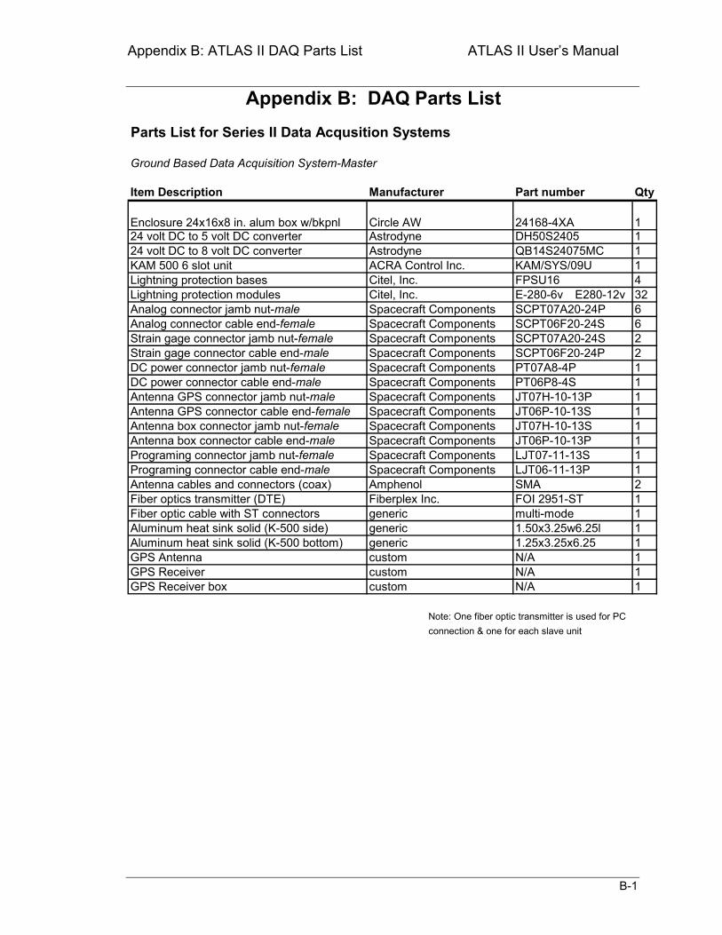
Appendix B: ATLAS II DAQ Parts List ATLAS II Users Manual
B-1
Appendix B: DAQ Parts List
Qty
11
QB14S24075MC 114
E-280-6v E280-12v 3266221111111121111111
Note: One fiber optic transmitter is used for PCconnection & one for each slave unit
N/AN/AN/A
Ground Based Data Acquisition System-Master
GPS AntennaGPS ReceiverGPS Receiver box
customcustomcustom
Fiber optic cable with ST connectors generic
Astrodyne
multi-mode
24168-4XA
KAM/SYS/09UFPSU16
LJT06-11-13P
DH50S2405
SCPT07A20-24SSCPT06F20-24PPT07A8-4PPT06P8-4S
KAM 500 6 slot unit
SMAFOI 2951-ST
JT06P-10-13SJT07H-10-13SJT06P-10-13PLJT07-11-13S
JT07H-10-13P
SCPT07A20-24PSCPT06F20-24S
Item Description
Spacecraft Components
Enclosure 24x16x8 in. alum box w/bkpnl
Spacecraft ComponentsSpacecraft Components
24 volt DC to 8 volt DC converter Astrodyne24 volt DC to 5 volt DC converter
Spacecraft Components
Lightning protection bases
Programing connector jamb nut-female
Antenna box connector jamb nut-femaleAntenna box connector cable end-male
Antenna GPS connector cable end-female Spacecraft ComponentsSpacecraft Components
DC power connector jamb nut-femaleDC power connector cable end-maleAntenna GPS connector jamb nut-male
Parts List for Series II Data Acqusition Systems
Spacecraft Components
ACRA Control Inc.Citel, Inc.Citel, Inc.Lightning protection modules
Analog connector jamb nut-maleAnalog connector cable end-femaleStrain gage connector jamb nut-femaleStrain gage connector cable end-male
Fiberplex Inc.Fiber optics transmitter (DTE)
Programing connector cable end-maleAntenna cables and connectors (coax)
Part number
Spacecraft ComponentsAmphenol
Manufacturer
Circle AW
Spacecraft ComponentsSpacecraft Components
Spacecraft ComponentsSpacecraft Components
1.50x3.25w6.25l1.25x3.25x6.25
Aluminum heat sink solid (K-500 side)Aluminum heat sink solid (K-500 bottom)
generic generic
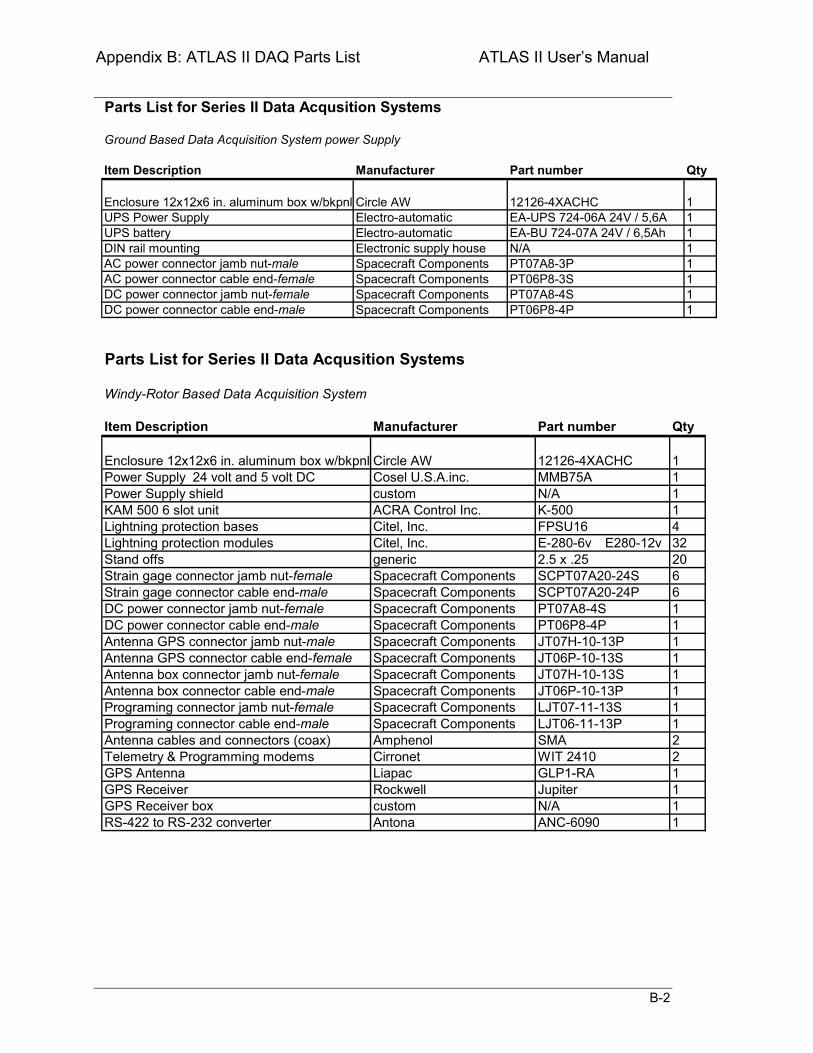
Appendix B: ATLAS II DAQ Parts List ATLAS II Users Manual
B-2
Parts List for Series II Data Acqusition Systems
Ground Based Data Acquisition System power Supply
Item Description Manufacturer Part number Qty
Enclosure 12x12x6 in. aluminum box w/bkpnl Circle AW 12126-4XACHC 1UPS Power Supply Electro-automatic EA-UPS 724-06A 24V / 5,6A 1UPS battery Electro-automatic EA-BU 724-07A 24V / 6,5Ah 1DIN rail mounting Electronic supply house N/A 1AC power connector jamb nut-male Spacecraft Components PT07A8-3P 1AC power connector cable end-female Spacecraft Components PT06P8-3S 1DC power connector jamb nut-female Spacecraft Components PT07A8-4S 1DC power connector cable end-male Spacecraft Components PT06P8-4P 1
Qty
11114
E-280-6v E280-12v 3220661111111122
GPS Antenna 1GPS Receiver 1GPS Receiver box custom N/A 1
1ANC-6090
Liapac GLP1-RARockwell Jupiter
RS-422 to RS-232 converter Antona
KAM 500 6 slot unit
Cosel U.S.A.inc.
Citel, Inc.generic
Lightning protection basesLightning protection modules
Citel, Inc.
Antenna GPS connector jamb nut-male
Enclosure 12x12x6 in. aluminum box w/bkpnl
ACRA Control Inc.
Circle AW
customPower Supply shield
Parts List for Series II Data Acqusition Systems
Windy-Rotor Based Data Acquisition System
PT07A8-4S
SCPT07A20-24SSCPT07A20-24P
Spacecraft ComponentsSpacecraft Components
Power Supply 24 volt and 5 volt DC
Stand offs
Item Description
Strain gage connector jamb nut-femaleStrain gage connector cable end-maleDC power connector jamb nut-femaleDC power connector cable end-male
Spacecraft ComponentsSpacecraft Components
Antenna cables and connectors (coax)
Antenna GPS connector cable end-femaleAntenna box connector jamb nut-femaleAntenna box connector cable end-male Spacecraft Components
Spacecraft ComponentsPrograming connector jamb nut-femalePrograming connector cable end-male
Telemetry & Programming modems
Part number
Spacecraft ComponentsAmphenol Cirronet
Spacecraft ComponentsSpacecraft ComponentsSpacecraft Components
Manufacturer
JT07H-10-13P
WIT 2410SMA
K-500
2.5 x .25
LJT06-11-13P
JT06P-10-13SJT07H-10-13SJT06P-10-13PLJT07-11-13S
PT06P8-4P
12126-4XACHCMMB75A
FPSU16
N/A
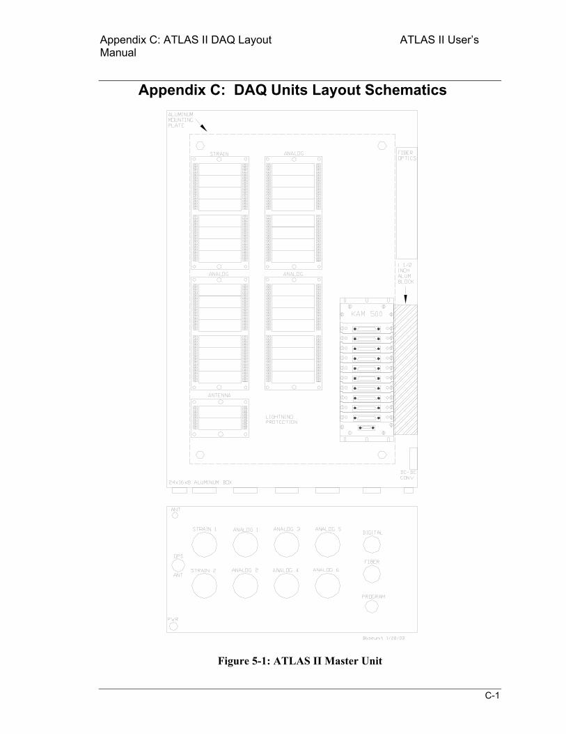
Appendix C: ATLAS II DAQ Layout ATLAS II Users Manual
C-1
Appendix C: DAQ Units Layout Schematics
Figure 5-1: ATLAS II Master Unit
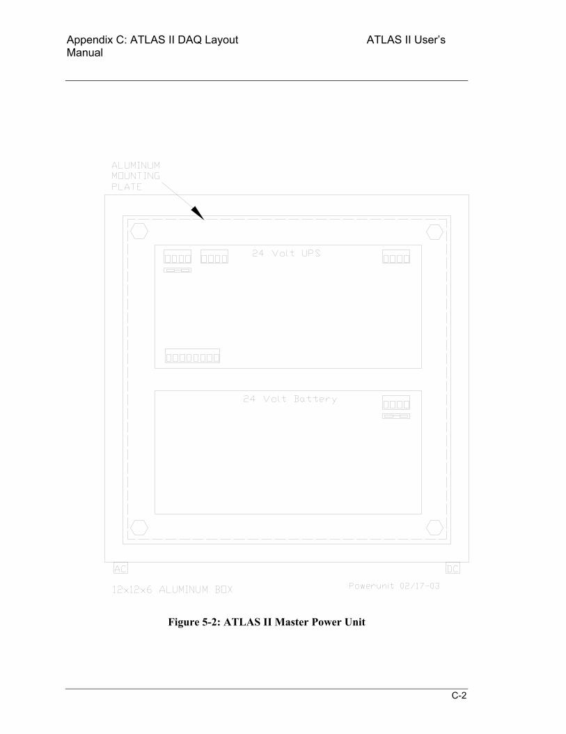
Appendix C: ATLAS II DAQ Layout ATLAS II Users Manual
C-2
Figure 5-2: ATLAS II Master Power Unit
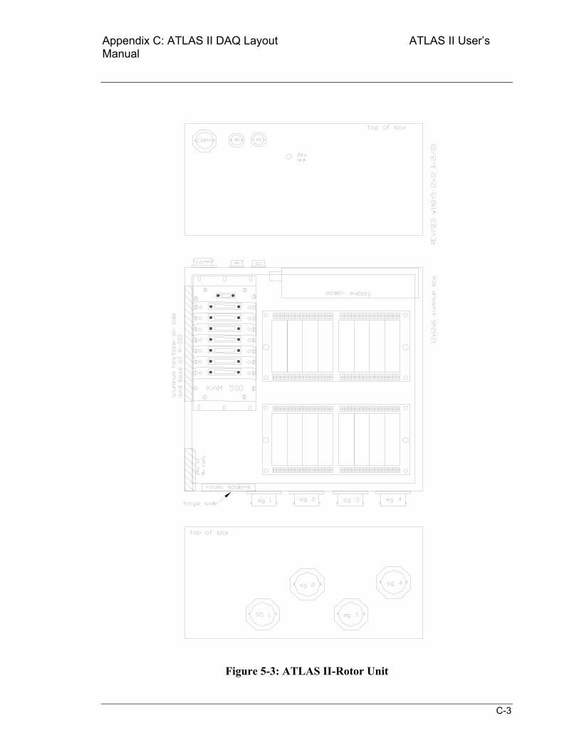
Appendix C: ATLAS II DAQ Layout ATLAS II Users Manual
C-3
Figure 5-3: ATLAS II-Rotor Unit
Appendix D: ATLAS II Configuring Modems ATLAS II Users Manual
D-0
Appendix D: Configuring Modems
D.1 Programming the Remote and Base Modems
D.1.2 Program the Remote RS-232 Modem
The remote RS-232 modem handles all asynchronous communications on the rotor. It must be programmed once to set the communications protocol parameters properly. Although only the bare module will be used in the RBU, it must be mounted in a complete modem housing, with RS-232 interface and serial cable connection, to be programmed.
1. Connect the modem 9-pin connector to the computer serial port and the power cable to the 8 V power source (usually a 8-VDC transformer that plugs into a 110 VAC wall outlet).
2. Start the COM2400 program (a DOS program located in directory COM24) and set the communciation rate to 38,400 bps using the computers <PgUp> or <PgDn> key. The communication rate is displayed on bottom left of the screen
3. Turn on the power to the modem.
4. The COM2400 program should display the modem firmware version and whether the modem is programmed as REMOTE or BASE. If the display is garbage characters, shift the program communication rate up or down and cycle the modem power again. The unit is probably programmed to operate at either 9,600, 19,200, 38,400 or 57,600.
5. After the version message is displayed, quickly press the F3 key to get the > prompt. Then proceed to program the modem unit. Enter the following commands (followed by the Enter key) at successive > prompts:
a) wn0 (sets network number to 0) b) wb0 (sets base/remote to remote) c) wdaa (sets destination address to AAH) d) wsaa (sets source address to AAH) e) wt0 (sets channel access mode to CSMA) f) wp1 (sets transmit power to 100 mW) g) sy0 (sets sync/async to asynchronous mode) h) sd020 (sets data transmit rate to 38,400 bps)
Use the computers <PgUp> or <PgDn> key to change the program communication speed to 38,400 before you con-
NOTE
Appendix D: ATLAS II Configuring Modems ATLAS II Users Manual
D-1
tinue the speed is displayed at the bottom left of the screen.
i) sp0 (sets packet mode to point-to-point) j) ph9c (sets hop duration to 9CH) k) pk0a (sets minimum packet length to 0AH) l) plf0 (sets maximum packet length to F0H) m) pt03 (sets packet timeout duration to 03H) n) pm40 (sets packet link margin to 40H) o) pr10 (sets ARQ retry limit to 10H) p) py02 (sets ARQ per-hop limit to 2H) q) pb08 (sets CSMA backoff constant to 08H) r) pp20 (sets CSMA persistence to 20H) s) ps0a (sets TDMA time slot to 0AH) t) pd0 (disables diversity antenna switching) u) m> (stores configuration to memory) v) z> (exits modem control mode)
6. The modem module should now be programmed, in asynchronous mode, and capable of communication. To check configuration settings, press F1 twice (to toggle DTR off and back on), and then press F3 once (to transmit wit:2400, which places the modem in configuration mode). Then check the settings programmed under Step 5, above. The current setting for each command can be displayed by typing the two-letter command followed by ? (i.e., sy?, to determine whether modem is set in sync or async mode).
D.1.3 Program the Base RS-232 Modem
The Base RS-232 modem handles all asynchronous communications on the ground. This modem module will be mounted in a modem case for normal use and will be located near the master GBU.
11. Connect the modem 9-pin connector to the computer serial port and the power cable to a 110 VAC power source.
7. Start the COM2400 program (a DOS program located in directory COM24) and set the communciation rate to 38,400 bps using the computers <PgUp> or <PgDn> key. The communication rate is displayed at the bottom left of the screen.
8. Turn on the power to the modem.
9. The COM2400 program should display the modem firmware version and whether it is REMOTE or BASE. If the display is garbage characters, shift the program communication rate up or down and cycle the modem power again. The unit is probably programmed to operate at either 9,600, 19,200, 38,400, or 57,600.
Appendix D: ATLAS II Configuring Modems ATLAS II Users Manual
D-2
10. After the version message is displayed, quickly press the F3 key to get the > prompt. Then proceed to program the modem unit. Enter the following commands (followed by the Enter key) at successive > prompts:
w) wn0 (sets network number to 0) x) wb1 (sets base/remote to base) y) wdaa (sets destination address to AAH) z) wsaa (sets source address to AAH) aa) wt0 (sets channel access mode to CSMA) bb) wp1 (sets transmit power to 100 mW) cc) sy0 (sets sync/async to asynchronous mode) dd) sd020 (sets data transmit rate to 38,000 bps)
Use the computers <PgUp> or <PgDn> key to change the program communication speed to 38,400 before you con-tinue the speed is displayed at the bottom left of the screen.
ee) sp0 (sets packet mode to point-to-point) ff) ph9c (sets hop duration to 9CH) gg) pk0a (sets minimum packet length to 0AH) hh) plf0 (sets maximum packet length to F0H) ii) pt03 (sets packet timeout duration to 03H) jj) pm40 (sets packet link margin to 40H) kk) pr10 (sets ARQ retry limit to 10H) ll) py02 (sets ARQ per-hop limit to 2H) mm) pb08 (sets CSMA backoff constant to 08H) nn) pp20 (sets CSMA persistence to 20H) oo) ps0a (sets TDMA time slot to 0AH) pp) pd0 (disables diversity antenna switching) qq) m> (stores configuration to memory) rr) z> (exits modem control mode)
11. The modem module should now be programmed, in asynchronous mode, and capable of communication. To check configuration settings, press F1 twice (to toggle DTR off and back on), and then press F3 once (to transmit wit:2400, which places the modem in configuration mode). Then check the settings programmed under Step 5, above. The current setting for each command can be displayed by typing the two-letter command followed by ? (i.e., sy?, to determine whether modem is set in sync or async mode).
NOTE
Appendix D: ATLAS II Configuring Modems ATLAS II Users Manual
D-3
D.2 Programming the Data Transmit and Receive Modems
D.2.1 Program the Transmit Data Modem to be Mounted in the RBU
The transmit data modem transmits acquired data from the RBU. Although only the bare module will be used in the RBU, it must be mounted in a complete modem housing, with RS-232 interface and serial cable connection, to be programmed.
12. Connect the modem to the computer serial port and the power cable to the 110 V power source.
13. Connect module signal pin 4 (CFG) to signal pin 1 (GND) on the modem module 11- pin connector. This jumper must be kept in place throughout the following procedure. This will require removal of the modem housing cover to allow access to the module connector.
14. Start the COM2400 program (a DOS program located in directory COM24) and set the communciation rate to 38,400 bps using the computers <PgUp> or <PgDn> key. The communication rate is displayed at the bottom left of the screen.
15. Turn on the power to the modem.
16. The COM2400 program should display the modem firmware version and whether it is REMOTE or BASE. If the display is garbage characters, shift the program commu-nication rate up or down and try again. Its probably programmed for 9600, 19,200, 38,400, or 57,600.
17. After the version message is displayed, quickly press the F3 key to get the > prompt. Then proceed to program the modem unit. Enter the following commands (followed by the Enter key) at successive > prompts:
ss) wn1 (sets network number to 1) tt) wb0 (sets base/remote to remote) uu) wdaa (sets destination address to AAH) vv) wsaa (sets source address to AAH) ww) wt0 (sets channel access mode to CSMA) xx) wp1 (sets transmit power to 100 mW) yy) sy1 (sets modem into synchronous mode this will not be effective until
z> is entered to terminate programming) zz) sd01f (sets data transmit rate to 38,400 bps)
Use the computers <PgUp> or <PgDn> key to change the program communication speed to 38,400 before you con-
NOTE
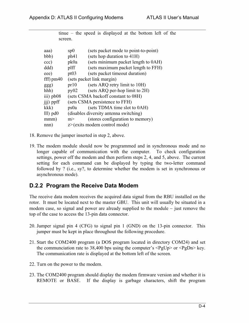
Appendix D: ATLAS II Configuring Modems ATLAS II Users Manual
D-4
tinue the speed is displayed at the bottom left of the screen.
aaa) sp0 (sets packet mode to point-to-point) bbb) ph41 (sets hop duration to 41H) ccc) pk0a (sets minimum packet length to 0AH) ddd) plff (sets maximum packet length to FFH) eee) pt03 (sets packet timeout duration) fff) pm40 (sets packet link margin) ggg) pr10 (sets ARQ retry limit to 10H) hhh) py02 (sets ARQ per-hop limit to 2H) iii) pb08 (sets CSMA backoff constant to 08H) jjj) ppff (sets CSMA persistence to FFH) kkk) ps0a (sets TDMA time slot to 0AH) lll) pd0 (disables diversity antenna switching) mmm) m> (stores configuration to memory) nnn) z> (exits modem control mode)
18. Remove the jumper inserted in step 2, above.
19. The modem module should now be programmed and in synchronous mode and no longer capable of communication with the computer. To check configuration settings, power off the modem and then perform steps 2, 4, and 5, above. The current setting for each command can be displayed by typing the two-letter command followed by ? (i.e., sy?, to determine whether the modem is set in synchronous or asynchronous mode).
D.2.2 Program the Receive Data Modem
The receive data modem receives the acquired data signal from the RBU installed on the rotor. It must be located next to the master GBU. This unit will usually be situated in a modem case, so signal and power are already supplied to the module − just remove the top of the case to access the 13-pin data connector.
20. Jumper signal pin 4 (CFG) to signal pin 1 (GND) on the 13-pin connector. This jumper must be kept in place throughout the following procedure.
21. Start the COM2400 program (a DOS program located in directory COM24) and set the communciation rate to 38,400 bps using the computers <PgUp> or <PgDn> key. The communication rate is displayed at the bottom left of the screen.
22. Turn on the power to the modem.
23. The COM2400 program should display the modem firmware version and whether it is REMOTE or BASE. If the display is garbage characters, shift the program
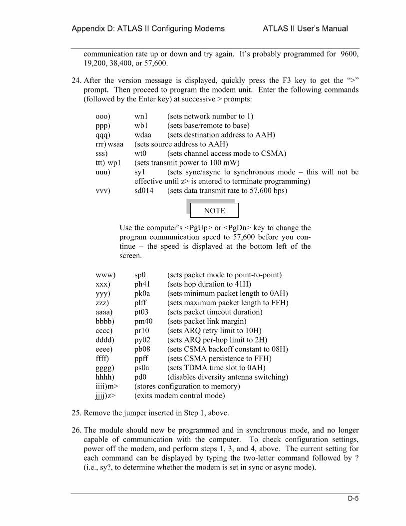
Appendix D: ATLAS II Configuring Modems ATLAS II Users Manual
D-5
communication rate up or down and try again. Its probably programmed for 9600, 19,200, 38,400, or 57,600.
24. After the version message is displayed, quickly press the F3 key to get the > prompt. Then proceed to program the modem unit. Enter the following commands (followed by the Enter key) at successive > prompts:
ooo) wn1 (sets network number to 1) ppp) wb1 (sets base/remote to base) qqq) wdaa (sets destination address to AAH) rrr) wsaa (sets source address to AAH) sss) wt0 (sets channel access mode to CSMA) ttt) wp1 (sets transmit power to 100 mW) uuu) sy1 (sets sync/async to synchronous mode this will not be
effective until z> is entered to terminate programming) vvv) sd014 (sets data transmit rate to 57,600 bps)
Use the computers <PgUp> or <PgDn> key to change the program communication speed to 57,600 before you con-tinue the speed is displayed at the bottom left of the screen.
www) sp0 (sets packet mode to point-to-point) xxx) ph41 (sets hop duration to 41H) yyy) pk0a (sets minimum packet length to 0AH) zzz) plff (sets maximum packet length to FFH) aaaa) pt03 (sets packet timeout duration) bbbb) pm40 (sets packet link margin) cccc) pr10 (sets ARQ retry limit to 10H) dddd) py02 (sets ARQ per-hop limit to 2H) eeee) pb08 (sets CSMA backoff constant to 08H) ffff) ppff (sets CSMA persistence to FFH) gggg) ps0a (sets TDMA time slot to 0AH) hhhh) pd0 (disables diversity antenna switching) iiii) m> (stores configuration to memory) jjjj) z> (exits modem control mode)
25. Remove the jumper inserted in Step 1, above.
26. The module should now be programmed and in synchronous mode, and no longer capable of communication with the computer. To check configuration settings, power off the modem, and perform steps 1, 3, and 4, above. The current setting for each command can be displayed by typing the two-letter command followed by ? (i.e., sy?, to determine whether the modem is set in sync or async mode).
NOTE
ATLAS II Distribution List ATLAS II Users Manual
6
Distribution List R. N. Clark USDA Agricultural Research Service P.O. Drawer 10 Bushland, TX 79012 Trudy Forsyth NREL 1617 Cole Boulevard Golden, CO 80401 Dave Jager NREL 1617 Cole Boulevard Golden, CO 80401 Byron Neal (3) USDA Agricultural Research Service P.O. Drawer 10 Bushland, TX 79012 Richard Santos NREL 1617 Cole Boulevard Golden, CO 80401 Dave Simms (3) NREL 1617 Cole Boulevard Golden, CO 80401 MS-0708 D. E. Berg, 6214 MS-0708 P. L. Jones, 6214 MS-0708 J. Ortiz-Moyet, 6214 MS-0708 M. A. Rumsey, 6214 MS-0708 H. J. Sutherland, 6214 MS-0708 P. S. Veers, 6214 (10) MS-0708 J. R. Zayas, 6214 MS-0899 Technical Library, 9616 (2) MS-9018 Central Technical Files, 8945-1 MS-0161 Patent & Licensing Office, 11500