Embed Size (px)
Citation preview

Mechanical Pipe Restraint
Mike DuguayAtlantic Sales Representative
www.clowcanada.com

Half Moon & Wedge Show

Thrust Force Water under pressure exerts UNBALANCEDThrust Force in piping systems
These Forcesmust be BALANCED to maintain the integrity of the piping system

Thrust Force
Created In Water Mains When The Pipeline
• Changes Direction• Stops• Change In Size

Thrust Calculation
Thrust Force Created Per 100 PSI of Water Pressure
6” Pipe
• 90 Degree Elbow – 5,290 LBS • 45 Degree Elbow – 2,860 • Dead End/Valve – 3,740
12” Pipe
• 90 – 19,350• 45 – 10,470• DE – 13,690
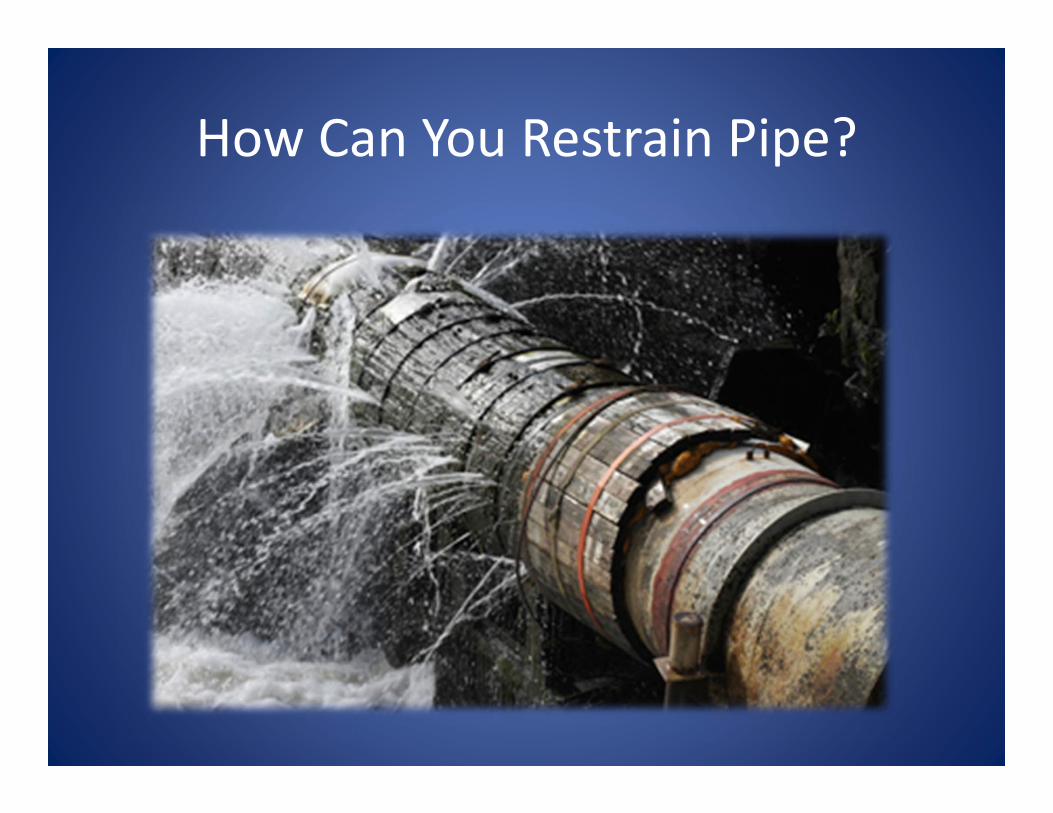
How Can You Restrain Pipe?

Different Pipe Connections
• MJ Fittings• Push‐On or Tyton Fittings• Flanged Fittings• PVC Fittings• Together• Fire Hydrants • Valves
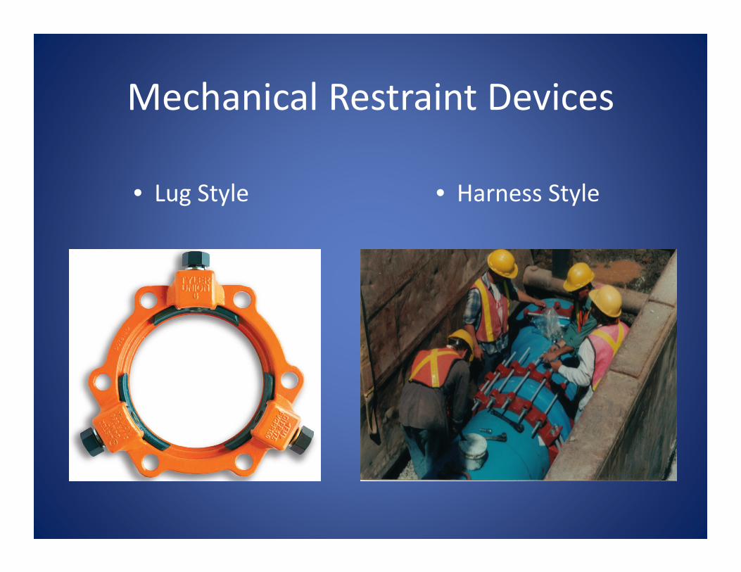
Mechanical Restraint Devices
• Lug Style • Harness Style

Lug Style Installation
Step 1
• Ensure the pipe end and MJ socket are clean• Slide restrainer onto pipe with lip toward pipe end
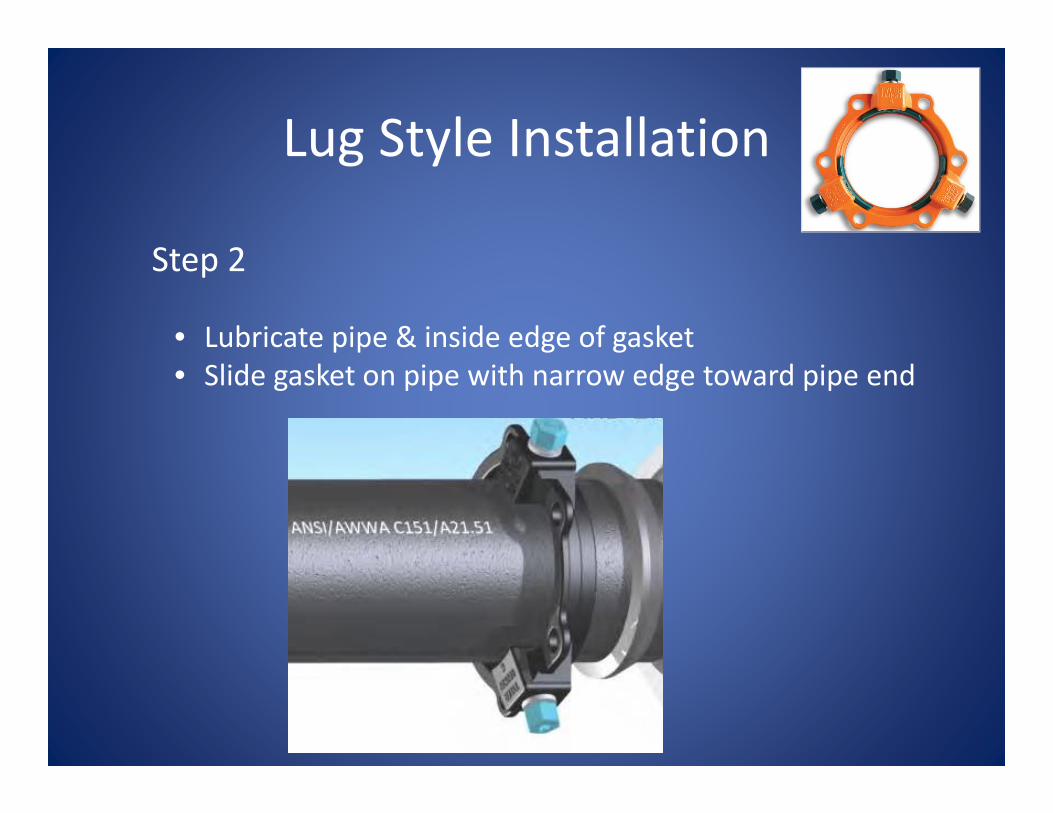
Lug Style Installation
Step 2
• Lubricate pipe & inside edge of gasket • Slide gasket on pipe with narrow edge toward pipe end

Lug Style Installation
Step 3
• Insert pipe and slide gasket firmly into recess• Joint must be kept straight
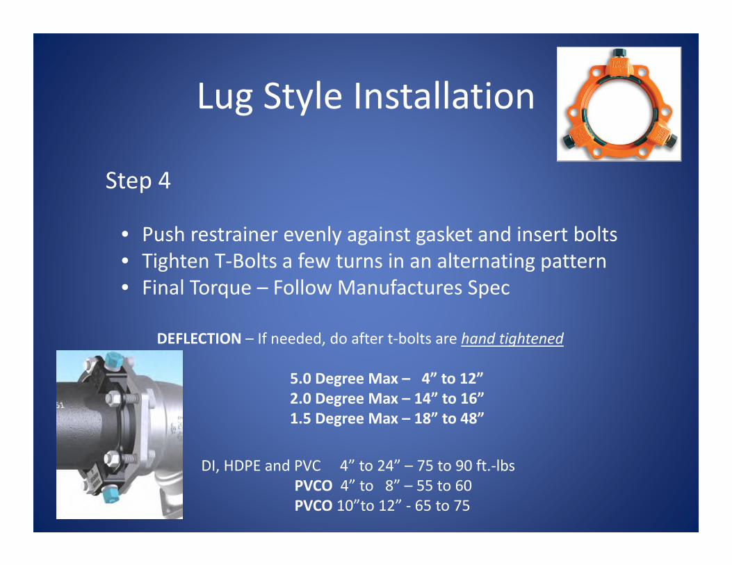
Lug Style Installation
• Push restrainer evenly against gasket and insert bolts• Tighten T‐Bolts a few turns in an alternating pattern• Final Torque – Follow Manufactures Spec
Step 4
DI, HDPE and PVC 4” to 24” – 75 to 90 ft.‐lbsPVCO 4” to 8” – 55 to 60PVCO 10”to 12” ‐ 65 to 75
DEFLECTION – If needed, do after t‐bolts are hand tightened
5.0 Degree Max – 4” to 12”2.0 Degree Max – 14” to 16”1.5 Degree Max – 18” to 48”

Lug Style Installation
• Hand tighten wedges until they contact the pipe• Turn each bolt NO MORE than one half turn each • Alternating pattern • Until bolt heads break off
Step 5
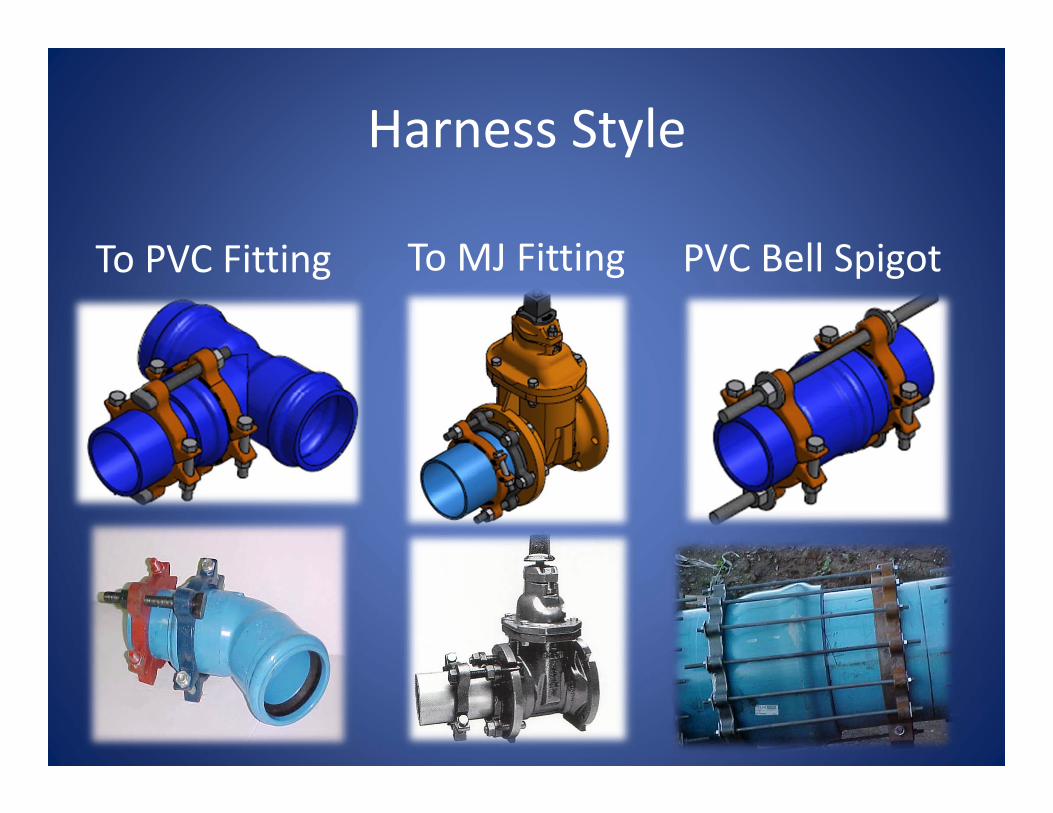
Harness Style
To PVC Fitting To MJ Fitting PVC Bell Spigot

Harness Style Installationto MJ Connection
Step 1
• Insert pipe into MJ Connection• Insert the long T‐Bolt into position
and mark 1” behind the end• Remove pipe and bolt
Long T‐Bolt

Harness Style Installationto MJ Connection
Step 2
• Clean Pipe End and MJ Bell• Slide Gland Ring on pipe, lube pipe end & inside the gasket. Slide Gasket on pipe
Gland Ring Lube Inside
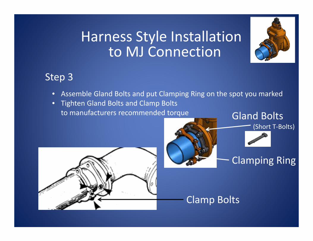
Harness Style Installationto MJ Connection
Step 3• Assemble Gland Bolts and put Clamping Ring on the spot you marked• Tighten Gland Bolts and Clamp Bolts
to manufacturers recommended torque Gland Bolts(Short T‐Bolts)
Clamp Bolts
Clamping Ring

Harness Style Installationto MJ Connection
Step 4
• Insert long T‐Bolts, putting one Retaining Nut between Gland Ring and Clamp Ring
Nuts
¾” x 7” T‐Boltused on 4” Pipe

Harness Style Installationto MJ Connection
Step 5
Retaining Nuts
• Tighten Retaining Nuts

THANK YOU !