Embed Size (px)
Citation preview
ATINER CONFERENCE PAPER SERIES No: LNG2014-1176
1
Athens Institute for Education and Research
ATINER
ATINER's Conference Paper Series
TRA2015-1562
Vlad Suru
Lecturer
University of Craiova
Romania
Alexandru Bitoleanu
Professor
University of Craiova
Romania
Mihaita Linca
Lecturer
University of Craiova
Romania
Indirect Current Control of a Filtering
and Regeneration System used in DC
Substations for Urban Traction
ATINER CONFERENCE PAPER SERIES No: TRA2015-1562
An Introduction to
ATINER's Conference Paper Series
ATINER started to publish this conference papers series in 2012. It includes only the
papers submitted for publication after they were presented at one of the conferences
organized by our Institute every year. This paper has been peer reviewed by at least two
academic members of ATINER.
Dr. Gregory T. Papanikos
President
Athens Institute for Education and Research
This paper should be cited as follows:
Suru, V., Bitoleanu, A. and Linca, M. (2015). "Indirect Current Control of a
Filtering and Regeneration System used in DC Substations for Urban
Traction", Athens: ATINER'S Conference Paper Series, No: TRA2015-1562.
Athens Institute for Education and Research
8 Valaoritou Street, Kolonaki, 10671 Athens, Greece
Tel: + 30 210 3634210 Fax: + 30 210 3634209 Email: [email protected] URL:
www.atiner.gr
URL Conference Papers Series: www.atiner.gr/papers.htm
Printed in Athens, Greece by the Athens Institute for Education and Research. All rights
reserved. Reproduction is allowed for non-commercial purposes if the source is fully
acknowledged.
ISSN: 2241-2891
23/08/2015
ATINER CONFERENCE PAPER SERIES No: TRA2015-1562
Indirect Current Control of a Filtering and Regeneration
System used in DC Substations for Urban Traction
Vlad Suru
Lecturer
University of Craiova
Romania
Alexandru Bitoleanu
Professor
University of Craiova
Romania
Mihaita Linca
Lecturer
University of Craiova
Romania
Abstract
The aim of this paper is an easier control method for an active filtering and
energy recovery system for high power DC traction substations. This system
converts the classical dc traction substation, with 6-pulse three-phase bridge
rectifier, in an “active substation”. The active substation allows both the
braking energy recovery to the power grid and the compensation of current
harmonics and reactive power of the current absorbed from the power grid. To
achieve this goal an indirect current control method had been investigated and
implemented both on a virtual system and on a scale experimental model.
Keywords: Active Traction Substations, Indirect Control, Urban DC Traction
Substations
Acknowledgments: This work was performed through the program Partnerships
in priority areas — PN II, conducted with the financial support of MEN –
UEFISCDI, project no. PN-II-PT-PCCA-2013-4-0564 (42/01.07.2014).
ATINER CONFERENCE PAPER SERIES No: TRA2015-1562
Introduction
The most urban railway vehicles are driven by electric motors which are
supplied by an overhead line using a pantograph or by a third rail. The dc
energy is delivered by the traction substations located along the railway line.
The traction substations are powered by a high or medium voltage three-
phase grid and they contain a transformer and a diode rectifier (6-pulse or 12-
pulse three-phase bridge rectifier). The output rectifier gives a dc voltage
having, mostly, the rated values of 750 V (tramways and underground railway,
including Bucharest), 1500 V (regional express and Intercity trains) and even 3
kV (South Africa trains) [1] – [3].
The need to reduce the electric energy consumption and increase the
efficiency requires two main actions:
1. The filtering of distorted current absorbed by the traction substations,
especially those which contain 6-pulse three-phase bridge rectifiers;
2. The energy recovery developed by the vehicle during the braking
process.
The second function is simplified by the train electric motors which can
convert the kinetic energy developed by the vehicle in electric energy.
Nowadays, just a small part of the resulted electric energy is reused and only
for auxiliary services. The remaining energy is simply wasted on the train
braking resistances (if not, the braking energy would increase the catenary
voltage).
The substation that allows the additional energy recovery to the power grid
and the current harmonics and reactive power compensation is called “active
substation” [1], [3], [4]. It also allows the dynamic compensation of the voltage
fluctuations on the high voltage line and the limitation of voltage drop across
the power line for some specific topologies [6] - [9]. Achieving these functions
requires specific structures and control methods, with high complexity [10] -
[13].
In this paper, an easier control method is analyzed, proposed by the authors
for a filtering and regeneration system (SISFREG). This system converts a
typical dc traction substation, with 6-pulse three-phase bridge rectifier, in an
“active substation”.
At first, the system structure and the meaning of each block is presented.
The system structure description is followed by the control block structure
substantiation based on the indirect current control.
Further the paper illustrates the system numeric model and also the
performances for the filtering mode, as well as, for the recovery mode.
Numerical data corresponds to a traction substation related to Bucharest
underground railway system.
The last section emphasizes the experimental results, for filtering mode,
obtained by implementing the proposed control method. In this last section, the
conclusions, concerning the performances and advantages of the analyzed
system, are also drawn.
ATINER CONFERENCE PAPER SERIES No: TRA2015-1562
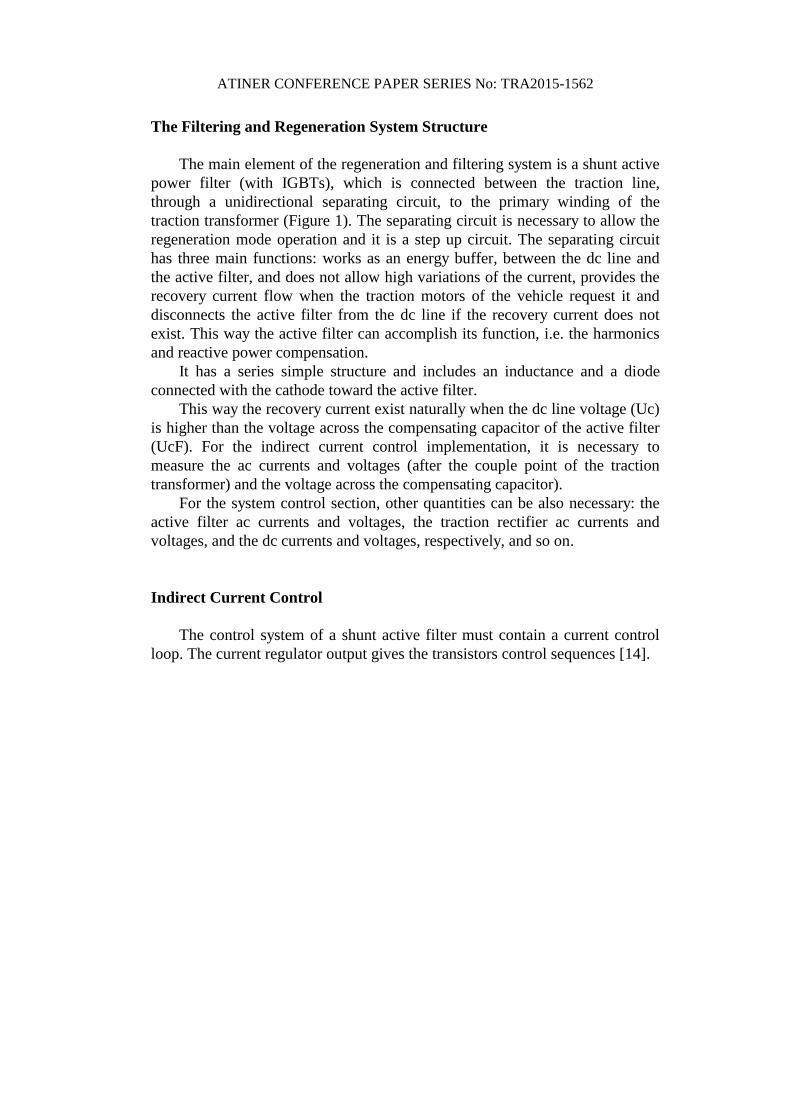
The Filtering and Regeneration System Structure
The main element of the regeneration and filtering system is a shunt active
power filter (with IGBTs), which is connected between the traction line,
through a unidirectional separating circuit, to the primary winding of the
traction transformer (Figure 1). The separating circuit is necessary to allow the
regeneration mode operation and it is a step up circuit. The separating circuit
has three main functions: works as an energy buffer, between the dc line and
the active filter, and does not allow high variations of the current, provides the
recovery current flow when the traction motors of the vehicle request it and
disconnects the active filter from the dc line if the recovery current does not
exist. This way the active filter can accomplish its function, i.e. the harmonics
and reactive power compensation.
It has a series simple structure and includes an inductance and a diode
connected with the cathode toward the active filter.
This way the recovery current exist naturally when the dc line voltage (Uc)
is higher than the voltage across the compensating capacitor of the active filter
(UcF). For the indirect current control implementation, it is necessary to
measure the ac currents and voltages (after the couple point of the traction
transformer) and the voltage across the compensating capacitor).
For the system control section, other quantities can be also necessary: the
active filter ac currents and voltages, the traction rectifier ac currents and
voltages, and the dc currents and voltages, respectively, and so on.
Indirect Current Control
The control system of a shunt active filter must contain a current control
loop. The current regulator output gives the transistors control sequences [14].
ATINER CONFERENCE PAPER SERIES No: TRA2015-1562
Figure 1. The Block Schematic of the Regenerating and Compensating System
for DC Traction Substations with Three-phase Bridge Rectifier
Direct control refers to the active filter output current adjustment and
indirect current control involves ac grid current adjustment [10], [11], [15].
There are two possibilities in order to obtain the desired grid current: based
on the distorted load current (pq theory based method, synchronous reference
based method, etc.) and based on the dc voltage controller.
In the regeneration mode, a grid current control loop is necessary. The grid
current must be an active current with a distortion enclosed in the standards.
Therefore, the most adequate control method is the indirect current control
based on dc voltage controller [5].
To explain the above conclusion, the energy stored in the compensating
capacitor is defined as:
To explain the above conclusion, the energy stored in the compensating
capacitor is defined as:
2
2
1CdC uCE (1)
obtaining the instantaneous power changed by it,
dt
duuCp C
CdC (2)
The voltage across the capacitor is expressed as the sum between the
continuous component, which is the prescribed value (Ucp) and the alternative
component (uc~) (Figure 2).
ATINER CONFERENCE PAPER SERIES No: TRA2015-1562
~CCpC uUu (3)
The mean value of the voltage is constant, in steady state, so its derivative
is the alternative component derivative. Moreover, approximating:
)( ~ CpCCpC UuUu (4)
The instantaneous power becomes,
CCpC
CpdC iUdt
duUCp ~ (5)
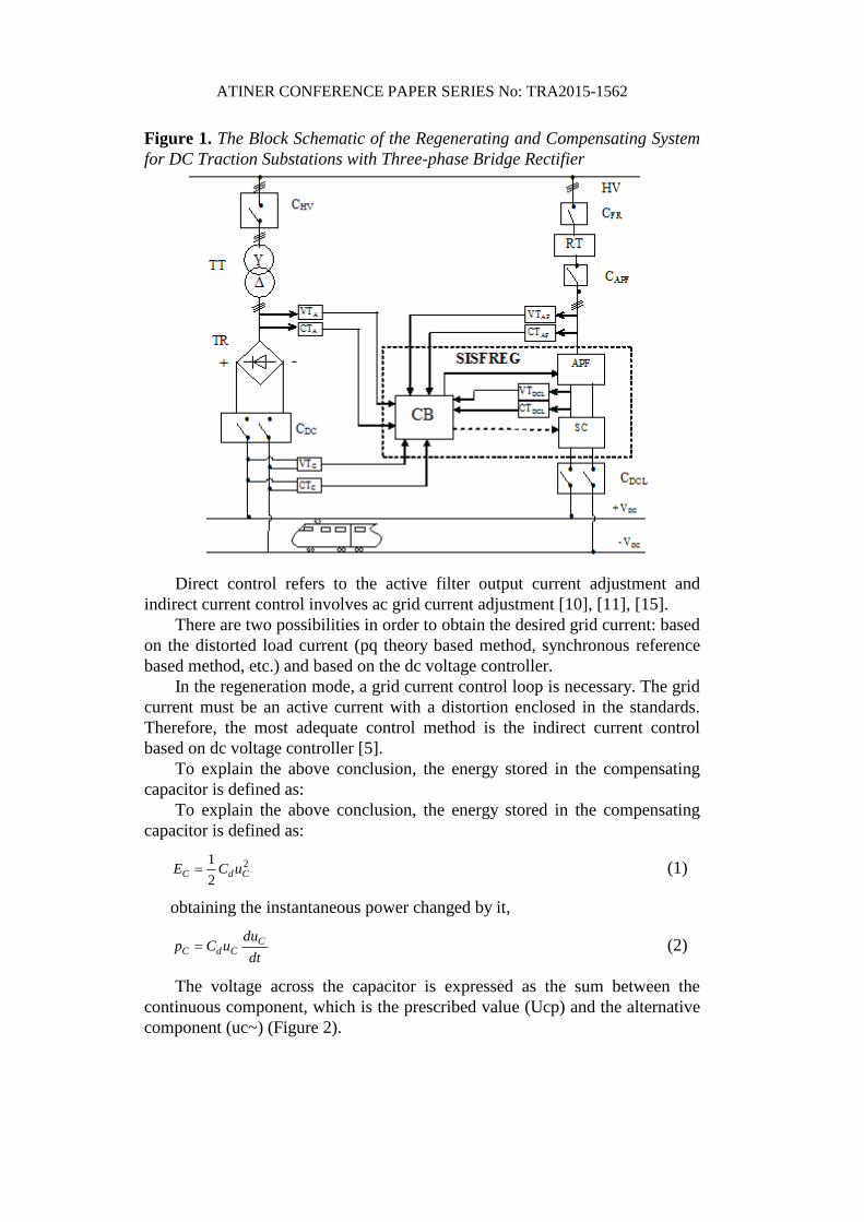
Taking into consideration the typical variation of the voltage across the
compensating capacitor of a three-phase shunt active filter, tm0 and tm1 are the
time moments corresponding to two consecutive lowest values, and tM is the
time moment corresponding to the highest voltage value (Figure 2).
The meanings of the mentioned periods are:
[tm0, tm1] – the alternative component period (1/6 of the ac grid voltage );
[tm0, tM] – the period in which the capacitor receive energy from the power
grid;
[tM, tm1] – the period in which the capacitor gives energy to the grid;
The corresponding active powers are obtained as mean values using (5):
dtitt
Udtdt
duUC
ttP
M
m
M
m
t
tC
mM
Cp
t
t
CCpd
mM
dC
00 0
~
0
1
11 (6)
Figure 2. Voltage on the Compensating Capacitor (ucd) and its Prescribed
Value (Ucp)
dtitt
Udtdt
duUC
ttP
m
M
m
M
t
tC
Mm
Cp
t
t
CCpd
Mm
dC
11
1
~
1
2
11 (7)
In (6) and (7) the first integrals are equal with opposite sign and represent
the voltage oscillation,
ATINER CONFERENCE PAPER SERIES No: TRA2015-1562
CCC
t
t
Ct
t
C UUUdtdt
dudt
dt
du m
M
M
m
minmax~~ 1
0
(8)
The last two integrals represent the continuous components of the current
through the capacitor:
dtitt
Idtitt
Im
M
M
m
t
tC
Mm
dC
t
tC
mM
dC
1
0 1
2
0
1
1;
1 (9)
Replacing (8) and (9) in (6) and (7), there can be defined the currents IdC1 and
IdC2:
C
Mm
ddCC
mM
ddC U
tt
CIU
tt
CI
1
2
0
1 ; (10)
The mean current on the whole period (T/6, the same as for power in a three
phase symmetrical system) is the sum between the two currents:
MmmM
CddCdCdCtttt
UCIII10
21
11 (11)
Inserting the period and the relative period in which the voltage increases,
6/;
6
001
T
ttx
Ttt mMmm
(12)
The mean current during a period is defined as follow:
6/)1(
21
Txx
xUCI CddC
(13)
ATINER CONFERENCE PAPER SERIES No: TRA2015-1562
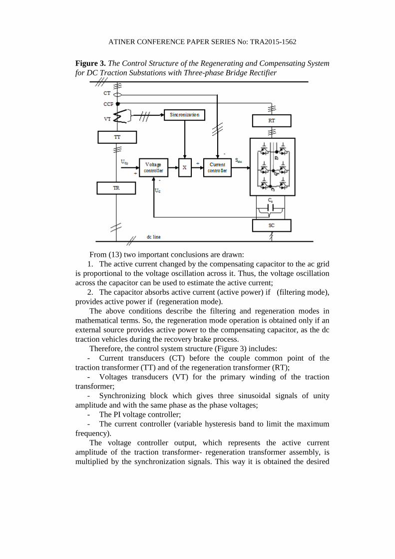
Figure 3. The Control Structure of the Regenerating and Compensating System
for DC Traction Substations with Three-phase Bridge Rectifier
From (13) two important conclusions are drawn:
1. The active current changed by the compensating capacitor to the ac grid
is proportional to the voltage oscillation across it. Thus, the voltage oscillation
across the capacitor can be used to estimate the active current;
2. The capacitor absorbs active current (active power) if (filtering mode),
provides active power if (regeneration mode).
The above conditions describe the filtering and regeneration modes in
mathematical terms. So, the regeneration mode operation is obtained only if an
external source provides active power to the compensating capacitor, as the dc
traction vehicles during the recovery brake process.
Therefore, the control system structure (Figure 3) includes:
- Current transducers (CT) before the couple common point of the
traction transformer (TT) and of the regeneration transformer (RT);
- Voltages transducers (VT) for the primary winding of the traction
transformer;
- Synchronizing block which gives three sinusoidal signals of unity
amplitude and with the same phase as the phase voltages;
- The PI voltage controller;
- The current controller (variable hysteresis band to limit the maximum
frequency).
The voltage controller output, which represents the active current
amplitude of the traction transformer- regeneration transformer assembly, is
multiplied by the synchronization signals. This way it is obtained the desired

ATINER CONFERENCE PAPER SERIES No: TRA2015-1562
current grid. To the current controller output there are obtained the control
signals for the voltage inverter transistors.
Passing and operating in the regeneration mode exist naturally, these
processes being conditioned by the following aspects:
1. The compensating capacitor voltage control loop, keeps the voltage to
the reference value, with deviations not exceeding 5% [2];
2. When Uc>UcF, the diode is forward biased and allows the existence of
the recovery current; the voltage error applied to the voltage controller becomes
negative, and the control block prescribes to the active filter an active current
with opposite phase to the grid voltage.
The Simulink Model and Numerical Results
The Simulink model of the system in Figure 3 is illustrated in Figure 4. It
can be seen that the model contains all the structural components grouped in
Simulink blocks making the model easier to be understood and debugged:
- three-phase power grid - 20 kV three-phase sinusoidal voltage source;
- The traction transformer and traction rectifier – the 6-pulse diode
rectifier with its corresponding transformer and smoothing filter which feeds
the catenary;
- Catenary / vehicle – this block implements the dc power line with a
train which accelerates or decelerates;
- The active filter containing:
o The adapting transformer
o The interface filter (1st order, inductive)
o The power inverter
o The interface circuit (which includes the interface diode and
compensating capacitor);
o The APF control block.
ATINER CONFERENCE PAPER SERIES No: TRA2015-1562
Figure 4. The Simulink Model of the Regenerating and Compensating System
for DC Traction Substations with Three-phase Bridge Rectifier
traction
timprecovery
Discrete,
Ts = 1e-005 s.
pow ergui
acc
v+-
A
B
C
a
b
c
Traction transformer
A
B
C
+
-
Traction rectifier
ul
ulp
uc
ucp
iF
is
ir
ur
c - zi
V+
V-
R
S
TModul IGBT
FZ1500R33HE3
Three-phase inverter
R
S
T
N
Three-phase
power grid
IabcA
B
C
a
b
c
IabcA
B
C
a
b
c
Vabc
IabcA
B
C
a
b
c
Vabc
IabcA
B
C
a
b
c
Relay
Rectifier
InMean
Pc P catenary
InMean
K1 IFab
A
B
C
a
b
c
Interface Filter
uc
Vin+
Vin-
Vout+
Vout-
Interface CircuitI catenary
Grid
ulp
Pc
is
ir
ur-K-
ulp
ucp
irp
ir
is
ur
DC-Link
i+
-
A
B
C
a
b
c
Compensator
transformer
IcR
Regim
v
Mas_UcR
af
U*
icc
UcR+
UcR-
Catenary/Vehicle
Catenary
grid current controliFab
uac
uc u
ab
-iS bc
ir ab
grid connect
START
K2
K1
c-zi
APF ctrl
The model can function in two modes:
- Traction / compensation – when the Catenary/Vehicle block acts like
the train accelerates.. In this case, the three-phase traction rectifier is functional
consuming power from the power grid and supplying the catenary. In turn, the
active compensator, is in filtering mode, compensating the distortion and
reactive power absorbed by the traction rectifier. The grid current is almost
sinusoidal in phase with the voltage.
- Braking / recovery - when the Catenary/Vehicle block acts like the train
decelerates. In this case, the three-phase traction rectifier is blocked, the voltage
on the catenary increases, opening the compensator interface circuit. Now, the
power flows from the catenary to the compensating capacitor and further to the
power grid via the compensator power inverter and transformer. The grid
current is also sinusoidal, but having reversed phase, the power is transferred
from the catenary to the power grid.
The operating mode (traction / braking) of the DC line is automatically
controlled to simulate the sequence traction – braking – traction. Every
transition is validated after the system reaches stationary regime.
The current absorbed by the traction substation, without the active filtering
system is illustrated in Figure 5. It is a typical current absorbed by a three-phase
thyristor rectifier which uses a Y- power transformer.
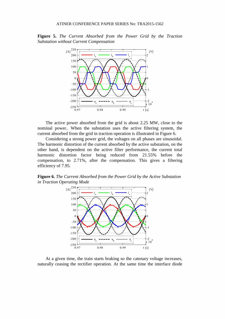
ATINER CONFERENCE PAPER SERIES No: TRA2015-1562
Figure 5. The Current Absorbed from the Power Grid by the Traction
Substation without Current Compensation
0.97 0.98 0.99 t [s]-250
-200
-150
-100
-50
0
50
100
150
200
250[A]
-2
-1
0
1
2
x 104
[V]
ia
ib
ic
ua
ub
uc
The active power absorbed from the grid is about 2.25 MW, close to the
nominal power.. When the substation uses the active filtering system, the
current absorbed from the grid in traction operation is illustrated in Figure 6.
Considering a strong power grid, the voltages on all phases are sinusoidal.
The harmonic distortion of the current absorbed by the active substation, on the
other hand, is dependent on the active filter performance, the current total
harmonic distortion factor being reduced from 21.55% before the
compensation, to 2.71%, after the compensation. This gives a filtering
efficiency of 7.95.
Figure 6. The Current Absorbed from the Power Grid by the Active Substation
in Traction Operating Mode
0.97 0.98 0.99 t [s]-250
-200
-150
-100
-50
0
50
100
150
200
250[A]
-2
-1
0
1
2
x 104
[V]
ia
ib
ic
ua
ub
uc
At a given time, the train starts braking so the catenary voltage increases,
naturally ceasing the rectifier operation. At the same time the interface diode
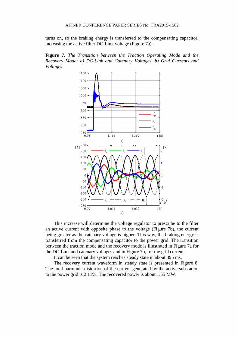
ATINER CONFERENCE PAPER SERIES No: TRA2015-1562
turns on, so the braking energy is transferred to the compensating capacitor,
increasing the active filter DC-Link voltage (Figure 7a).
Figure 7. The Transition between the Traction Operating Mode and the
Recovery Mode: a) DC-Link and Catenary Voltages, b) Grid Currents and
Voltages
0.95 1.151 1.352 t [s]750
800
850
900
950
1000
1050
1100
1150
uC
*
uC
udc
a)
0.99 1.011 1.032 t [s]-250
-200
-150
-100
-50
0
50
100
150
200
250[A]
-2
-1
0
1
2
x 104
[V]
ia
ib
ic
ua
ub
uc
b)
This increase will determine the voltage regulator to prescribe to the filter
an active current with opposite phase to the voltage (Figure 7b), the current
being greater as the catenary voltage is higher. This way, the braking energy is
transferred from the compensating capacitor to the power grid. The transition
between the traction mode and the recovery mode is illustrated in Figure 7a for
the DC-Link and catenary voltages and in Figure 7b, for the grid current.
It can be seen that the system reaches steady state in about 395 ms.
The recovery current waveform in steady state is presented in Figure 8.
The total harmonic distortion of the current generated by the active substation
to the power grid is 2.11%. The recovered power is about 1.55 MW.
ATINER CONFERENCE PAPER SERIES No: TRA2015-1562
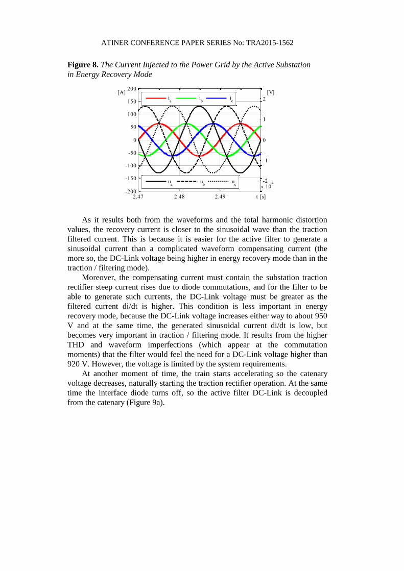
Figure 8. The Current Injected to the Power Grid by the Active Substation
in Energy Recovery Mode
2.47 2.48 2.49 t [s]-200
-150
-100
-50
0
50
100
150
200[A]
-2
-1
0
1
2
x 104
[V]
ia
ib
ic
ua
ub
uc
As it results both from the waveforms and the total harmonic distortion
values, the recovery current is closer to the sinusoidal wave than the traction
filtered current. This is because it is easier for the active filter to generate a
sinusoidal current than a complicated waveform compensating current (the
more so, the DC-Link voltage being higher in energy recovery mode than in the
traction / filtering mode).
Moreover, the compensating current must contain the substation traction
rectifier steep current rises due to diode commutations, and for the filter to be
able to generate such currents, the DC-Link voltage must be greater as the
filtered current di/dt is higher. This condition is less important in energy
recovery mode, because the DC-Link voltage increases either way to about 950
V and at the same time, the generated sinusoidal current di/dt is low, but
becomes very important in traction / filtering mode. It results from the higher
THD and waveform imperfections (which appear at the commutation
moments) that the filter would feel the need for a DC-Link voltage higher than
920 V. However, the voltage is limited by the system requirements.
At another moment of time, the train starts accelerating so the catenary
voltage decreases, naturally starting the traction rectifier operation. At the same
time the interface diode turns off, so the active filter DC-Link is decoupled
from the catenary (Figure 9a).
ATINER CONFERENCE PAPER SERIES No: TRA2015-1562
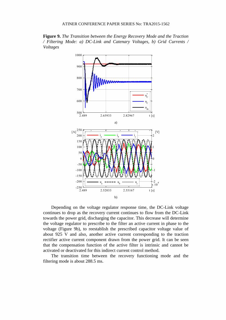
Figure 9. The Transition between the Energy Recovery Mode and the Traction
/ Filtering Mode: a) DC-Link and Catenary Voltages, b) Grid Currents /
Voltages
2.489 2.65933 2.82967 t [s]500
600
700
800
900
1000
uC
*
uC
udc
a)
2.489 2.52033 2.55167 t [s]-250
-200
-150
-100
-50
0
50
100
150
200
250[A]
-2
-1
0
1
2
x 104
[V]
ia
ib
ic
ua
ub
uc
b)
Depending on the voltage regulator response time, the DC-Link voltage
continues to drop as the recovery current continues to flow from the DC-Link
towards the power grid, discharging the capacitor. This decrease will determine
the voltage regulator to prescribe to the filter an active current in phase to the
voltage (Figure 9b), to reestablish the prescribed capacitor voltage value of
about 925 V and also, another active current corresponding to the traction
rectifier active current component drawn from the power grid. It can be seen
that the compensation function of the active filter is intrinsic and cannot be
activated or deactivated for this indirect current control method.
The transition time between the recovery functioning mode and the
filtering mode is about 288.5 ms.
ATINER CONFERENCE PAPER SERIES No: TRA2015-1562
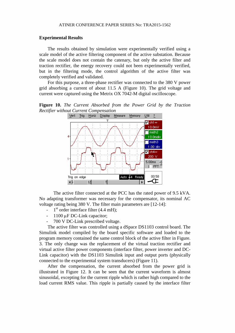
Experimental Results
The results obtained by simulation were experimentally verified using a
scale model of the active filtering component of the active substation. Because
the scale model does not contain the catenary, but only the active filter and
traction rectifier, the energy recovery could not been experimentally verified,
but in the filtering mode, the control algorithm of the active filter was
completely verified and validated.
For this purpose, a three-phase rectifier was connected to the 380 V power
grid absorbing a current of about 11.5 A (Figure 10). The grid voltage and
current were captured using the Metrix OX 7042-M digital oscilloscope.
Figure 10. The Current Absorbed from the Power Grid by the Traction
Rectifier without Current Compensation
The active filter connected at the PCC has the rated power of 9.5 kVA.
No adapting transformer was necessary for the compensator, its nominal AC
voltage rating being 380 V. The filter main parameters are [12-14]:
- 1st order interface filter (4.4 mH);
- 1100 F DC-Link capacitor;
- 700 V DC-Link prescribed voltage.
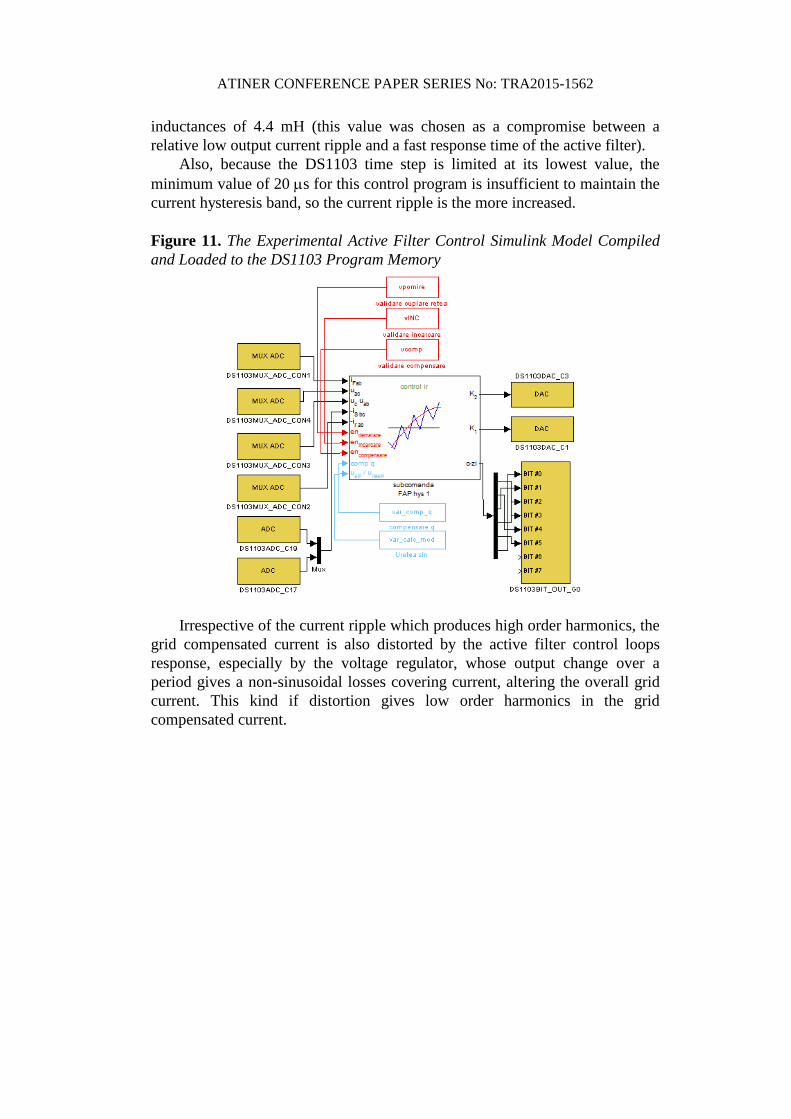
The active filter was controlled using a dSpace DS1103 control board. The
Simulink model compiled by the board specific software and loaded to the
program memory contained the same control block of the active filter in Figure.
3. The only change was the replacement of the virtual traction rectifier and
virtual active filter power components (interface filter, power inverter and DC-
Link capacitor) with the DS1103 Simulink input and output ports (physically
connected to the experimental system transducers) (Figure 11).
After the compensation, the current absorbed from the power grid is
illustrated in Figure 12. It can be seen that the current waveform is almost
sinusoidal, excepting for the current ripple which is rather high compared to the
load current RMS value. This ripple is partially caused by the interface filter
ATINER CONFERENCE PAPER SERIES No: TRA2015-1562
inductances of 4.4 mH (this value was chosen as a compromise between a
relative low output current ripple and a fast response time of the active filter).
Also, because the DS1103 time step is limited at its lowest value, the
minimum value of 20 s for this control program is insufficient to maintain the
current hysteresis band, so the current ripple is the more increased.
Figure 11. The Experimental Active Filter Control Simulink Model Compiled
and Loaded to the DS1103 Program Memory
Irrespective of the current ripple which produces high order harmonics, the
grid compensated current is also distorted by the active filter control loops
response, especially by the voltage regulator, whose output change over a
period gives a non-sinusoidal losses covering current, altering the overall grid
current. This kind if distortion gives low order harmonics in the grid
compensated current.
ATINER CONFERENCE PAPER SERIES No: TRA2015-1562
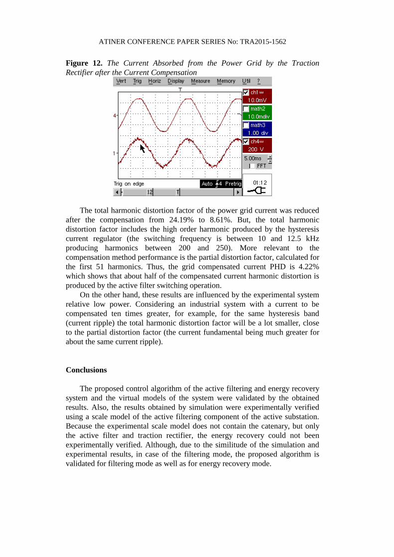
Figure 12. The Current Absorbed from the Power Grid by the Traction
Rectifier after the Current Compensation
The total harmonic distortion factor of the power grid current was reduced
after the compensation from 24.19% to 8.61%. But, the total harmonic
distortion factor includes the high order harmonic produced by the hysteresis
current regulator (the switching frequency is between 10 and 12.5 kHz
producing harmonics between 200 and 250). More relevant to the
compensation method performance is the partial distortion factor, calculated for
the first 51 harmonics. Thus, the grid compensated current PHD is 4.22%
which shows that about half of the compensated current harmonic distortion is
produced by the active filter switching operation.
On the other hand, these results are influenced by the experimental system
relative low power. Considering an industrial system with a current to be
compensated ten times greater, for example, for the same hysteresis band
(current ripple) the total harmonic distortion factor will be a lot smaller, close
to the partial distortion factor (the current fundamental being much greater for
about the same current ripple).
Conclusions
The proposed control algorithm of the active filtering and energy recovery
system and the virtual models of the system were validated by the obtained
results. Also, the results obtained by simulation were experimentally verified
using a scale model of the active filtering component of the active substation.
Because the experimental scale model does not contain the catenary, but only
the active filter and traction rectifier, the energy recovery could not been
experimentally verified. Although, due to the similitude of the simulation and
experimental results, in case of the filtering mode, the proposed algorithm is
validated for filtering mode as well as for energy recovery mode.
ATINER CONFERENCE PAPER SERIES No: TRA2015-1562
References
[1] Warin, Y., Lanselle, R., Thiounn, M. Active substation, World Congress on
Railway Research, 22-26 May, 2011, Lille, France.
[2] Henning, P.H., Fuchs, H.D., le Roux, A.D., Mouton, H.T. A 1.5-MW Seven-Cell
Series-Stacked Converter as an Active Power Filter and Regeneration Converter
for a DC Traction Substation, IEEE Trans. on Power Electronics, Vol.23, Issue 5,
2008, pp. 2230 - 2236.
[3] The “TICKET TO KYOTO” project, Overview of braking energy recovery
technologies in the public transport field, March 2011, www.tickettokyoto.eu.
[4] EP1985490 A1; 29 Oct 2008: System, substation and method for recovering brake
energy from railway vehicles, railway vehicles for this system.
[5] Toshihiko Tanaka, Norio Ishikura, Eiji Hiraki: A Constant DC Voltage Control
Based Compensation Method of an Active Power Quality Compensator for
Electrified Railways, IEEJ Trans 2009; 4: 435–441.
[6] Wada Hosny, Han-Eol Park, Joong-Ho Song: Investigation of Shunt Active Power
Filters in Railway Systems, Substation Installation, Journal of Energy and Power
Engineering 7 (2013) 1974-1979.
[7] Shishime, K., Practical Applications of the Railway Static Power Conditioner
(RPC) for Conventional Railways, MEIDEN Review, No. 156, 2012, pp. 38-41.
[8] Ortega, J.M., Ibaiondo, H., Romo, A. Kinetic Energy Recovery on Railway
Systems with Feedback to The Grid, World Congress on Railway Research, 22-
26 May, 2011, Lille, France.
[9] Ortega, J.M. Ingeber System for Kinetic Energy Recovery & Metro Bilbao
Experience, Rail Technological Forum for Internationalization, June 2011,
Madrid.
[10] Popescu, M., Bitoleanu, A., Suru, V. A DSP-Based Implementation of the p-q
Theory in Active Power Filtering under Nonideal Voltage Conditions, IEEE
Transaction on Industrial Informatics, Volume 9, Issue 2 May, 2013, pp. 880-
889.
[11] Mahanty, R. Indirect current controlled shunt active power filter for power
quality improvement, Electrical Power and Energy Systems Journal, nr. 62/2014,
pg. 441-449.
[12] Alexandru Bitoleanu, Mihaela Popescu, Vlad Suru, High Performance Shunt
Active Power Filter: Design Consideration and Experimental Evaluation, Analele
Universitatii Eftimie Murgu Resita Fascicola de Inginerie, ANUL XXI, NR. 3,
2014, ISSN 1453 - 7397, pp 153-166.
[13] Suru V., Popescu M., Pătraşcu A. Using dSPACE in the Shunt Static
Compensators Control, Annals of The University of Craiova, No 37, 2013, ISSN
1842-4805, pp 94-99.
[14] Constantin Vlad Suru, Mihaita Linca, Cristina Alexandra Patrascu, Evaluation of
current control methods in three-phase shunt active power filters system, Analele
Universitatii Eftimie Murgu Resita Fascicola de Inginerie, ANUL XXI, NR. 3,
2014, ISSN 1453 - 7397, pp 177-188.
[15] Patjoshi, R.K., Mahapatra, K.K. Performance comparison of direct and indirect
current control techniques applied to a sliding mode based shunt active power
filter, India Conference (INDICON), 2013 Annual IEEE, ISBN 978-1-4799-
2274-1, pp 1-5.