Embed Size (px)
Citation preview
ATINER CONFERENCE PAPER SERIES No: LNG2014-1176
1
Athens Institute for Education and Research
ATINER
ATINER's Conference Paper Series
TRA2015-1561
Alexandra Preda
Assistant
University of Craiova
Romania
Mihaela Popescu
Professor
University of Craiova
Romania
Mihaita Linca
Lecturer
University of Craiova
Romania
Conservative Power Theory (CPT)
Method Applied in the Indirect Current
Control for Active D.C. Traction
Substations
ATINER CONFERENCE PAPER SERIES No: TRA2015-1561
An Introduction to
ATINER's Conference Paper Series
ATINER started to publish this conference papers series in 2012. It includes only the
papers submitted for publication after they were presented at one of the conferences
organized by our Institute every year. This paper has been peer reviewed by at least two
academic members of ATINER.
Dr. Gregory T. Papanikos
President
Athens Institute for Education and Research
This paper should be cited as follows:
Preda, A., Popescu, M. and Linca, M. (2015). "Conservative Power Theory
(CPT) Method Applied in the Indirect Current Control for Active D.C.
Traction Substations", Athens: ATINER'S Conference Paper Series,
No: TRA2015-1561.
Athens Institute for Education and Research
8 Valaoritou Street, Kolonaki, 10671 Athens, Greece
Tel: + 30 210 3634210 Fax: + 30 210 3634209 Email: [email protected] URL:
www.atiner.gr
URL Conference Papers Series: www.atiner.gr/papers.htm
Printed in Athens, Greece by the Athens Institute for Education and Research. All rights
reserved. Reproduction is allowed for non-commercial purposes if the source is fully
acknowledged.
ISSN: 2241-2891
23/08/2015
ATINER CONFERENCE PAPER SERIES No: TRA2015-1561
Conservative Power Theory (CPT) Method Applied in the
Indirect Current Control for Active D.C. Traction Substations
Alexandra Preda
Assistant
University of Craiova
Romania
Mihaela Popescu
Professor
University of Craiova
Romania
Mihaita Linca
Lecturer
University of Craiova
Romania
Abstract
This paper analyzes a control method for a filtering and regenerative
system which can be attached to a classical DC traction substation. This allows
the conversion of the classical traction substation in an active traction
substation. The latter absorbs, from the power grid, only the active component
of the substation current, which is computed using the Conservative Power
Theory. On the other hand, the active traction substation can inject to the power
grid the braking energy recovery current, which is also an active current. For
this purpose, an indirect current control method had been implemented on a
virtual system and validated on a scale experimental model.
Keywords: Active Filtering, Conservative Power Theory, Indirect Control,
Railway DC Traction Substations
Acknowledgments: This work was performed through the program Partnerships
in priority areas — PN II, conducted with the financial support of MEN –
UEFISCDI, project no. PN-II-PT-PCCA-2013-4-0564 (42/01.07.2014).
ATINER CONFERENCE PAPER SERIES No: TRA2015-1561
Introduction
In the paper a control method for a filtering and regenerative system is
analyzed.
This allows the conversion of the classical dc traction substations in active
traction substations [1], [2]. The main properties of the active traction
substations are that they absorb, from the power grid, only the active current, in
the same time they can inject active current to the power grid. This means that
the harmonic current of the traction rectifier is compensated by the active
compensator and the braking energy can be recovered to the power grid.
After a brief introduction in this section, the next section presents the
filtering and recovery component of the active substation. This system contains
a shunt active compensator with IGBTs and a unidirectional circuit for the
interface between the compensator and the catenary. The active compensator is
connected on one side to the catenary through the separating circuit, and on the
other side, to the power grid through the step up recovery transformer.
The description of each block is followed by the control block structure
substantiation based on the indirect current control and the active load current
computation, in the “The Control Block Structure Substantiation based on the
Indirect Current Control and the Grid Desired Current Control and the Grid
Desired Current Computation” section. The control part is a cascade structure
that contains two loops, one very fast for control of the grid current and other
for DC voltage control. The desired grid current is computed by adding two
currents. First is the active current absorbed by the traction rectifier, using the
Conservative Power Theory (CPT), the newest theory about non-sinusoidal
regime, developed by Paolo Tenti. The second component is the active current
required to cover the losses into the active power filter and to keep constant the
compensating capacitor voltage. This current is obtained from the DC voltage
controller (PI controller). The desired grid current is compared to the real grid
current and the error is applied to the current controller (hysteresis controller).
Thus, the “The Active Current Definitions in Three-Phase System based on
the CPT under Non-sinusoidal Voltage” section, the main part of the paper,
presents the active current definitions based on the CPT under non-sinusoidal
voltage. Further, in the “The Simulink Model of the Regenerating and
Compensating System for DC Traction Substations with 12-pulse Bridge
Parallel Rectifier” section the paper describes the complete Simulink model of
the regenerating and compensating system for dc traction substations with 12-
pulse bridge parallel rectifier. The obtained simulation results are illustrated in
the “The Simulation Results for the Filtering and the Recovery Mode” section.
The model is analyzed for the filtering mode, as well as, for the recovery mode.
The last section emphasizes the experimental results, for the filtering
mode, obtained by implementing the proposed control method, this time, on a
scale model of the regenerating and compensating system for dc traction
substations with a six-pulse bridge rectifier. The conclusions, concerning the
ATINER CONFERENCE PAPER SERIES No: TRA2015-1561
performances and advantages of the analyzed system, are drawn at the end of
the paper.
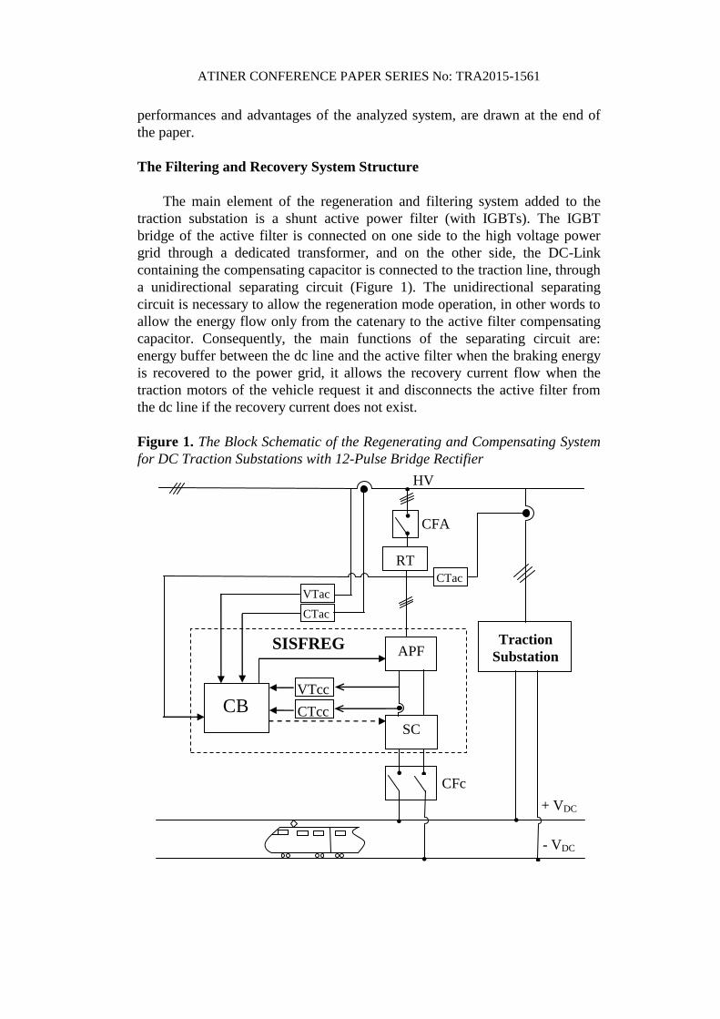
The Filtering and Recovery System Structure
The main element of the regeneration and filtering system added to the
traction substation is a shunt active power filter (with IGBTs). The IGBT
bridge of the active filter is connected on one side to the high voltage power
grid through a dedicated transformer, and on the other side, the DC-Link
containing the compensating capacitor is connected to the traction line, through
a unidirectional separating circuit (Figure 1). The unidirectional separating
circuit is necessary to allow the regeneration mode operation, in other words to
allow the energy flow only from the catenary to the active filter compensating
capacitor. Consequently, the main functions of the separating circuit are:
energy buffer between the dc line and the active filter when the braking energy
is recovered to the power grid, it allows the recovery current flow when the
traction motors of the vehicle request it and disconnects the active filter from
the dc line if the recovery current does not exist.
Figure 1. The Block Schematic of the Regenerating and Compensating System
for DC Traction Substations with 12-Pulse Bridge Rectifier
HV
+ VDC
- VDC
APF
●
● CFA
SC
● ●
CFc
●
●
●
RT
VTac
CTac
CB VTcc
SISFREG
Traction
Substation
CTcc
●
●
CTac
ATINER CONFERENCE PAPER SERIES No: TRA2015-1561
The transition from filtering to energy recovery occurs naturally as well as
the transition from energy recovery to filtering. This means that when the train
is braking, the catenary voltage increases naturally ceasing the traction rectifier
operation. At the same time, the separating diode turns on increasing the
compensating capacitor voltage. The voltage regulator response is a current
prescribed to the active filter with opposite phase to the grid voltage, to
discharge the capacitor and reduce the DC-Link voltage back to the operating
value. In a similar manner, when the train stops braking and accelerates, the
catenary voltage decreases and the traction rectifier enters normal operation.
Because the DC-Link voltage was kept at the operating value during recovery,
the capacitor voltage is now greater than the catenary voltage and the
separating diode turns off naturally. Because the traction rectifier is again
functional, its current is again compensated by the active filter. As seen, there
is no additional control needed to make the active filter switch from the
filtering mode to the energy recovery mode and back to the filtering mode. All
the transitions are accomplished naturally by the traction rectifier and
separating diode on one hand, and by the DC-Link voltage regulator on the
other hand which adapts at the DC-Link voltage change.
The Control Block Structure Substantiation based on the Indirect Current
Control and the Grid Desired Current Control and the Grid Desired
Current Computation
Direct Current Control vs. Indirect Current Control
Regarding the active power filter current regulating loop, in the literature
two directions are covered:
- Direct current control – which is the classical approach [3]-[5]
and it assumes that the current loop controls the current injected by the
active filter to the power grid, i.e. the current through the interface filter
inductors. As a result, the grid compensated current is the sum of the
load current and the filter compensating current. For this approach, the
active filter control block must compute the nonlinear load non-active
current (the compensating current) and the active current needed by the
active filter to charge the DC-Link capacitor and to cover the losses.
Regarding the conventional current flows, the compensating current is
prescribed positive to the current loop (because it is generated by the
active filter and supplied to the nonlinear load) and the looses covering
current is negative because it is absorbed from the power grid by the
active filter;
- Indirect current control – it is a new approach [6]-[8] and it
assumes that the active filter current loop controls not the generated
current but the grid current at the PCC side. This way, the current loop
reference current is the sum of the grid desired current (typically the
nonlinear load active current) and the active filter losses covering

ATINER CONFERENCE PAPER SERIES No: TRA2015-1561
current. The losses covering current is the same as the previous case and
is obtained in the same way. The grid desired current is obtained using
any current decomposition method [9]-[14]. Regarding the conventional
current flows, the grid desired current is positive (because being an
active current, is absorbed from the power grid and thus is in phase with
the grid voltage) and the losses covering current is also positive (also
absorbed from the power grid) but with opposite sign as in the previous
case. This is because the current transducer is oriented from the grid to
the active filter while previously its orientation was from the filter
towards the power grid.
The Active Filter Control Block for the Indirect Current Control with the Grid
Desired Current Computation
The block control schematic of the active filter for the indirect control is
illustrated in Figure 2.
The control structure was created starting from the classical control
structure of a shunt active power filter. Consequently, it contains two regulating
loops, an internal fast response regulating loop for the grid current control and
an external low response regulating loop for the compensating capacitor
voltage control.
Figure 2. The Active Filter Control Structure for the Indirect Current Control
with the Grid Desired Current Computation
For simplicity, the internal loop uses three simple and reliable hysteresis
current regulators (CR), one for each phase, with their known advantages and
disadvantages (they are very simple, robust and with no tuning required, but the
switching frequency of the power inverter is variable).
The voltage regulating loop, on the other hand is using a single PI regulator
(VR). The regulator output is the amplitude of the current needed to charge the
compensating capacitor and to cover the system losses. Accordingly, the
regulator output is multiplied with three unitary sinusoidal signals (in phase
+ VR CR Σ X Σ
uDC-Link
-
+
+
igrid -
idesired
gating
signals u*
DC-Link
Phase
Lock
Loop
Desired current
computation
(CPT)
ugrid
1sinωt
iLoad
ATINER CONFERENCE PAPER SERIES No: TRA2015-1561
with the power grid voltages) giving the three prescribed losses covering grid
currents.
The losses covering current is added to the grid desired current and the
result is applied to the hysteresis current regulator. At the current regulator
reaction input the instantaneous grid current is applied (from the Current
measurement Simulink block for the virtual system and from the
DS1103MUX_ADC_CON3 Simulink block for the experimental system –
which is the block giving the virtualized signal from the DS1103 board
multiplexed analog to digital converter – the signal at the ADC input is
received from the corresponding experimental system current transducer).
At the three-phase hysteresis current controller output the gating signals for
the power transistors are available. In the virtual system this signals are applied
to the virtual IGBTs gates and for the experimental system, these signals are
applied to the DS1103_BIT_OUT_G0 Simulink output port, which is the port
corresponding to the board digital outputs. The digital outputs are applied to
the power IGBTs through a specialized amplification and protection circuitry.
The Active Current Definitions in Three-Phase System based on the CPT
under Non-sinusoidal Voltage
As it was mentioned in the previous section, the reference current is the
sum of the grid desired current (i*grid) and the active filter losses covering
current (iaF). The grid desired current is obtained using the CPT current
decomposition method [12]-[14]. It will be calculated from the load current
depending on the compensation goals. Thus, if partial compensation is needed,
the grid desired current will be computed using relation (1):
aFrLaLgrid iiii *
(1)
In this case the active filter will compensate only the distortion component.
On the other hand, for the total compensation, the active filter will
compensate the entire non-active current components and the grid desired
current will be expressed as follows:
aFaLgrid iii *
(2)
The CPT current components (the active and reactive terms) are defined as
follows:
ui aL 2U
P (3)
uBuW
i b
rL
2U
(4)
where,
- i means the column vector containing the components of i on each phase (iR,
iS, iT);
ATINER CONFERENCE PAPER SERIES No: TRA2015-1561
- P and W are the three-phase active power respective the reactive energy of
the load.
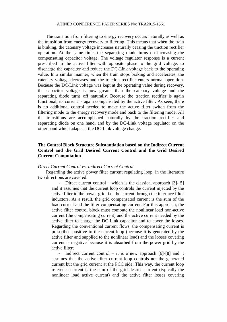
The Simulink Model of the Regenerating and Compensating System for
DC Traction Substations with 12-pulse Bridge Parallel Rectifier
The Simulink model of the active filtering and energy recovery system
added to the traction substation in Figure 3 contains all the mentioned
components modeled using SymPowerSystems blocks. It must be mentioned
that for creating the virtual model, a specific Simulink library was developed.
This way, a common structure with modular blocks was obtained, adding or
replacing specific blocks depending on the conducted study. The virtual system
is therefore complex with lots of variables taken into account.
The main components of the model are:
- The catenary block – which models the DC traction feeder and the
passing train; one of the block input signals is controlling the catenary behavior
– the train is accelerating so it is absorbing power from the traction substation
or the train is decelerating so it is producing power increasing the catenary
voltage;
Figure 3. The Simulink Model of the Regenerating and Compensating System
for DC Traction Substations with 12-pulse Bridge Rectifier
traction
time
Discrete,
Ts = 2e-006 s.
pow ergui
CPT symmetriciFab
uac
uc u
ab
-iS bc
-ir ab
enstart
enload
encompensation
comp mode
usin
/ unesin
K2
K1
c-zi
hys APF control (CPT_grid)
braking
acc
v+-
A
B
C
+
-
Universal Bridge2
A
B
C
+
-
Universal Bridge1
A
B
C
a2
b2
c2
a3
b3
c3
Traction
substation transformer
x THD
THDr1
ul
ulp
uc
ucp
is
ir
ur
c - zi
V+
V-
R
S
TModul IGBT
FZ1500R33HE3
Three-phase inverter
IabcA
B
C
a
b
c
Vabc
IabcA
B
C
a
b
c
InMean
Pc P catenary
Memory
InMean
K1 IFab
u1FA
B
C
a
b
c
Interface
filter
I catenary
Grid
ulp
Pc
is
ir
ur
-K-
-K-
ur
ulp
ucp
iincpr
ir
is
DC-Link
12
uc
Vin+
Vin-
Vout+
Vout-
Catenary
separating circuit
IcR
Regim
v
Mas_UcR
af
U*
icc
UcR+
UcR-
Catenary
A
B
C
a
b
c
APF
transformer
R
S
T
N
20 kV non-sinusoidal
power grid
- The traction substation – composed of:

ATINER CONFERENCE PAPER SERIES No: TRA2015-1561
o Traction substation transformer (two secondary windings);
o Traction rectifiers (one for each winding);
o DC line smoothing filter (LC);
- The active power filter composed of:
o Three phase IGBT power inverter;
o 1st order interface filter;
o Adapting power transformer;
o Catenary separating circuit block (containing the compensating
capacitor and the separating diode);
o APF control block;
The active power filter must accomplish two individual tasks:
- Compensating the traction substation current absorbed from the grid
when power is transferred to the catenary (the trains are accelerating). As a
result, the active traction substation is absorbing a sinusoidal current from the
power grid minimizing the losses and the distortion produced to the grid;
- Recovering the braking energy when the trains are decelerating and the
power is produced from the catenary towards the active substation. As a result,
the active traction substation is injecting to the power grid a sinusoidal current
with opposite phase to the voltage.
The Simulation Results for the Filtering and the Recovery Mode
Considering the system is working in traction mode close to the nominal
working point (the train is consuming from the traction substation about 2.2
MW, thus the 12-pulse rectifier is functional and absorbing active and non-
active power from the grid) the active filtering system added to the traction
substation has to compensate the non-sinusoidal current in Figure 4. Because
the 12-pulse rectifier is uncontrolled the absorbed reactive power is low and
only due to the diodes natural switching point. Also, because of the 12-pulse
rectifier typical low harmonic distortion factor, the distortion power to be
compensated is again relatively reduced, but considering the high power of the
system, the compensation of these non-active powers leads to a significant
losses reduction.
ATINER CONFERENCE PAPER SERIES No: TRA2015-1561
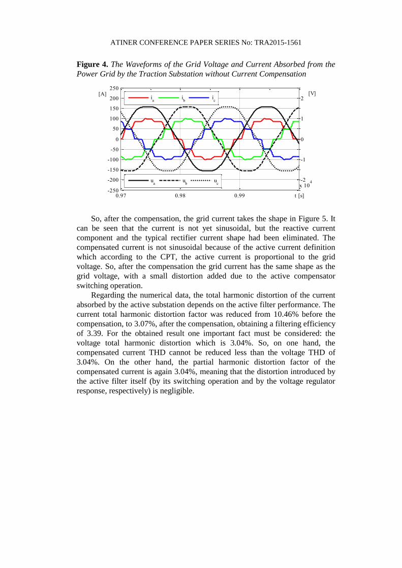
Figure 4. The Waveforms of the Grid Voltage and Current Absorbed from the
Power Grid by the Traction Substation without Current Compensation
0.97 0.98 0.99 t [s]-250
-200
-150
-100
-50
0
50
100
150
200
250[A]
-2
-1
0
1
2
x 104
[V]
ia
ib
ic
ua
ub
uc
So, after the compensation, the grid current takes the shape in Figure 5. It
can be seen that the current is not yet sinusoidal, but the reactive current
component and the typical rectifier current shape had been eliminated. The
compensated current is not sinusoidal because of the active current definition
which according to the CPT, the active current is proportional to the grid
voltage. So, after the compensation the grid current has the same shape as the
grid voltage, with a small distortion added due to the active compensator
switching operation.
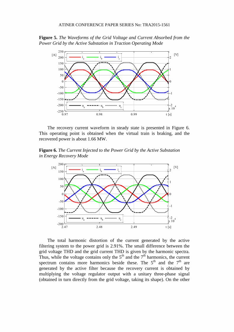
Regarding the numerical data, the total harmonic distortion of the current
absorbed by the active substation depends on the active filter performance. The
current total harmonic distortion factor was reduced from 10.46% before the
compensation, to 3.07%, after the compensation, obtaining a filtering efficiency
of 3.39. For the obtained result one important fact must be considered: the
voltage total harmonic distortion which is 3.04%. So, on one hand, the
compensated current THD cannot be reduced less than the voltage THD of
3.04%. On the other hand, the partial harmonic distortion factor of the
compensated current is again 3.04%, meaning that the distortion introduced by
the active filter itself (by its switching operation and by the voltage regulator
response, respectively) is negligible.
ATINER CONFERENCE PAPER SERIES No: TRA2015-1561
Figure 5. The Waveforms of the Grid Voltage and Current Absorbed from the
Power Grid by the Active Substation in Traction Operating Mode
0.97 0.98 0.99 t [s]-250
-200
-150
-100
-50
0
50
100
150
200
250[A]
-2
-1
0
1
2
x 104
[V]
ia
ib
ic
ua
ub
uc
The recovery current waveform in steady state is presented in Figure 6.
This operating point is obtained when the virtual train is braking, and the
recovered power is about 1.66 MW.
Figure 6. The Current Injected to the Power Grid by the Active Substation
in Energy Recovery Mode
2.47 2.48 2.49 t [s]-200
-150
-100
-50
0
50
100
150
200[A]
-2
-1
0
1
2
x 104
[V]
ia
ib
ic
ua
ub
uc
The total harmonic distortion of the current generated by the active
filtering system to the power grid is 2.91%. The small difference between the
grid voltage THD and the grid current THD is given by the harmonic spectra.
Thus, while the voltage contains only the 5th
and the 7th
harmonics, the current
spectrum contains more harmonics beside these. The 5th
and the 7th
are
generated by the active filter because the recovery current is obtained by
multiplying the voltage regulator output with a unitary three-phase signal
(obtained in turn directly from the grid voltage, taking its shape). On the other
ATINER CONFERENCE PAPER SERIES No: TRA2015-1561
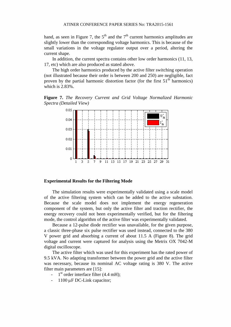
hand, as seen in Figure 7, the 5th
and the 7th
current harmonics amplitudes are
slightly lower than the corresponding voltage harmonics. This is because of the
small variations in the voltage regulator output over a period, altering the
current shape.
In addition, the current spectra contains other low order harmonics (11, 13,
17, etc) which are also produced as stated above.
The high order harmonics produced by the active filter switching operation
(not illustrated because their order is between 200 and 250) are negligible, fact
proven by the partial harmonic distortion factor (for the first 51th
harmonics)
which is 2.83%.
Figure 7. The Recovery Current and Grid Voltage Normalized Harmonic
Spectra (Detailed View)
Experimental Results for the Filtering Mode
The simulation results were experimentally validated using a scale model
of the active filtering system which can be added to the active substation.
Because the scale model does not implement the energy regeneration
component of the system, but only the active filter and traction rectifier, the
energy recovery could not been experimentally verified, but for the filtering
mode, the control algorithm of the active filter was experimentally validated.
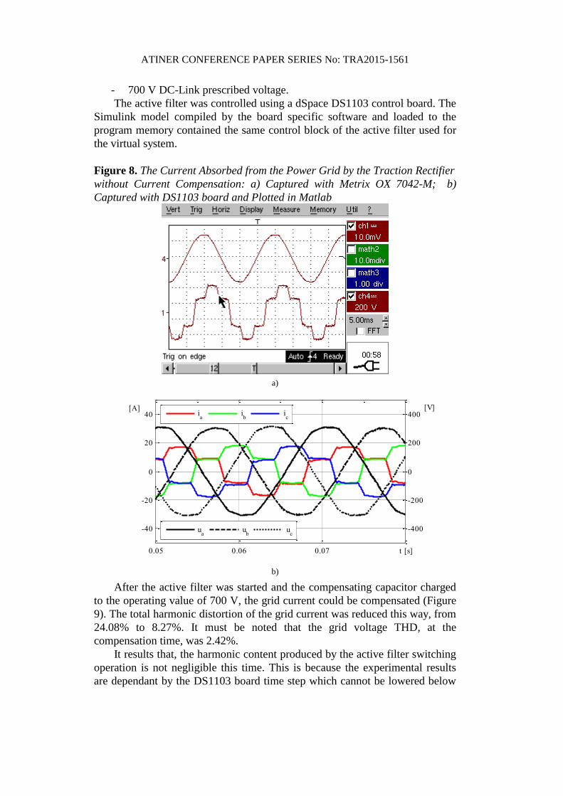
Because a 12-pulse diode rectifier was unavailable, for the given purpose,
a classic three-phase six pulse rectifier was used instead, connected to the 380
V power grid and absorbing a current of about 11.5 A (Figure 8). The grid
voltage and current were captured for analysis using the Metrix OX 7042-M
digital oscilloscope.
The active filter which was used for this experiment has the rated power of
9.5 kVA. No adapting transformer between the power grid and the active filter
was necessary, because its nominal AC voltage rating is 380 V. The active
filter main parameters are [15]:
- 1st order interface filter (4.4 mH);
- 1100 F DC-Link capacitor;
ATINER CONFERENCE PAPER SERIES No: TRA2015-1561
- 700 V DC-Link prescribed voltage.
The active filter was controlled using a dSpace DS1103 control board. The
Simulink model compiled by the board specific software and loaded to the
program memory contained the same control block of the active filter used for
the virtual system.
Figure 8. The Current Absorbed from the Power Grid by the Traction Rectifier
without Current Compensation: a) Captured with Metrix OX 7042-M; b)
Captured with DS1103 board and Plotted in Matlab
a)
0.05 0.06 0.07 t [s]
-40
-20
0
20
40[A]
-400
-200
0
200
400[V]
ia
ib
ic
ua
ub
uc
b)
After the active filter was started and the compensating capacitor charged
to the operating value of 700 V, the grid current could be compensated (Figure
9). The total harmonic distortion of the grid current was reduced this way, from
24.08% to 8.27%. It must be noted that the grid voltage THD, at the
compensation time, was 2.42%.
It results that, the harmonic content produced by the active filter switching
operation is not negligible this time. This is because the experimental results
are dependant by the DS1103 board time step which cannot be lowered below
ATINER CONFERENCE PAPER SERIES No: TRA2015-1561
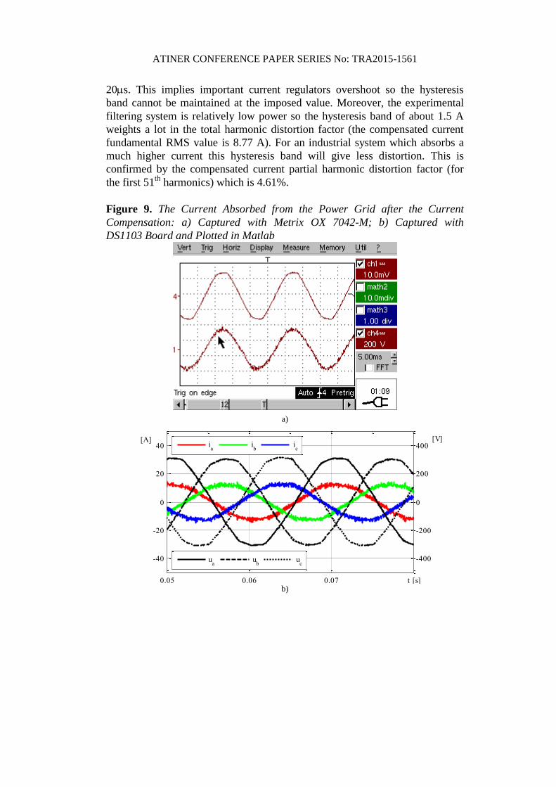
20s. This implies important current regulators overshoot so the hysteresis
band cannot be maintained at the imposed value. Moreover, the experimental
filtering system is relatively low power so the hysteresis band of about 1.5 A
weights a lot in the total harmonic distortion factor (the compensated current
fundamental RMS value is 8.77 A). For an industrial system which absorbs a
much higher current this hysteresis band will give less distortion. This is
confirmed by the compensated current partial harmonic distortion factor (for
the first 51th
harmonics) which is 4.61%.
Figure 9. The Current Absorbed from the Power Grid after the Current
Compensation: a) Captured with Metrix OX 7042-M; b) Captured with
DS1103 Board and Plotted in Matlab
a)
0.05 0.06 0.07 t [s]
-40
-20
0
20
40[A]
-400
-200
0
200
400[V]
ia
ib
ic
ua
ub
uc
b)
ATINER CONFERENCE PAPER SERIES No: TRA2015-1561
Conclusions
Considering the simulation results, the proposed algorithm was validated
both for the filtering mode and for the energy recovery mode. Also, the
simulation results, for the filtering mode, were experimentally validated using a
scale model of the active filtering system. The scale model does not implement
the energy regeneration component of the system, so the energy recovery could
not been experimentally verified (being verified only by simulation). Although,
considering the similitude between the simulation and the experimental results,
for the filtering mode, the correctness of the proposed algorithm is proved both
for filtering and energy recovery.
References
[1] Warin Y., Lanselle R., Thiounn M., Active substation, World Congress on
Railway Research, 22-26 May, 2011, Lille, France.
[2] The “TICKET TO KYOTO” project, Overview of braking energy recovery
technologies in the public transport field, March 2011, www.tickettokyoto.eu.
[3] Popescu M., Bitoleanu A, Suru V., A DSP-Based Implementation of the p-q
Theory in Active Power Filtering Under Nonideal Voltage Conditions, IEEE
Transactions on Industrial Informatics, Vol. 9 , Issue 2, Digital Object Identifier:
10.1109/TII.2012.2223223 , ISSN 1551-3203, May 2013, pp. 880-889.
[4] Popescu M., Bitoleanu A., Dobriceanu M., Lincă M., “On the Cascade Control
System Tuning for Shunt Active Filters Based on Modulus Optimum Criterion”,
Proc. of European Conference on Circuit Theory and Design, August 2009,
Antalya, Turkey, pp. 137-140
[5] Bitoleanu A., Popescu Mihaela, Marin D., Dobriceanu M., LCL Interface Filter
Design for Shunt Active Power Filters, 3rd International Symposium on
Electrical Engineering and Energy Converters, September 24-25, 2009, Suceava.
[6] Mahanty R., Indirect current controlled shunt active power filter for power quality
improvement, Electrical Power and Energy Systems Journal, nr. 62/2014, pg.
441-449.
[7] Quoc-Nam Trinh and Hong-Hee Lee, An Advanced Current Control Strategy for
Three-Phase Shunt Active Power Filters, IEEE TRANSACTIONS ON
INDUSTRIAL ELECTRONICS, VOL. 60, NO. 12, DECEMBER 2013, pp.
5400-5410.
[8] Jong-Gyu Hwang Æ Yong-Jin Park Æ Gyu-Ha Choi, Indirect current control of
active filter for harmonic elimination with novel observer-based noise reduction
scheme, Electrical Engineering (2005) 87: 261–266 DOI 10.1007/s00202-004-
0229-3.
[9] Czarnecki L. S., "Currents’ Physical Components (CPC) in Circuits with
Nonsinusoidal Voltages and Currents. Part 1: Single-Phase Linear Circuits, "
Journal on Electric Power Quality and Utilization, Vol. XI, No. 2, 2005, pp. 27-
48.
[10] Czarnecki L. S., "Currents’ Physical Components (CPC) in Circuits with
Nonsinusoidal Voltages and Currents Part 2: Three-Phase Linear Circuits, "
EPQU Journal, Vol. XXII, No. 1, 2006, pp. 3-13.
ATINER CONFERENCE PAPER SERIES No: TRA2015-1561
[11] Tenti P., Mattavelli P., A Time-Domain Approach to Power Term Definitions
under Non-Sinusoidal Conditions, 6th International Workshop on Power
Definitions and Measurements under Non-Sinusoidal Conditions, Milano,
October 13-15, 2003.
[12] Tenti P., Mattavelli P., Tedeschi Elisabetta, Compensation Techniques based on
Reactive Power Conservation, Electrical Power Quality and Utilisation Journal,
Vol. XIII, No. 1, 2007.
[13] Tenti P., Conservative Power Theory Seminar: A theoretical background to
understand energy issues of electrical networks under non-sinusoidal conditions
and to approach measurement, accountability and control problems in smart
grids, UNICAMP – UNESP Sorocaba, August 2012.
[14] Suru V., Popescu Mihaela, Pătraşcu Alexandra, Using dSPACE in the Shunt
Static Compensators Control, Annals of The University of Craiova, No 37, 2013,
ISSN 1842-4805, pp 94-99.