Embed Size (px)
Citation preview
ATF2 FB/FF layout
Javier Resta Lopez(JAI, Oxford University)
for the FONT project group
FONT meetingJanuary 11, 2007
Introduction
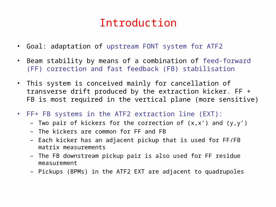
• Goal: adaptation of upstream FONT system for ATF2
• Beam stability by means of a combination of feed-forward (FF) correction and fast feedback (FB) stabilisation
• This system is conceived mainly for cancellation of transverse drift produced by the extraction kicker. FF + FB is most required in the vertical plane (more sensitive)
• FF+ FB systems in the ATF2 extraction line (EXT):– Two pair of kickers for the correction of (x,x’) and (y,y’)– The kickers are common for FF and FB– Each kicker has an adjacent pickup that is used for FF/FB matrix measurements– The FB downstream pickup pair is also used for FF residue measurement– Pickups (BPMs) in the ATF2 EXT are adjacent to quadrupoles
Kicker arrangement
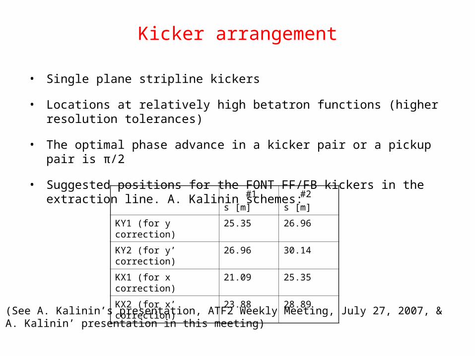
• Single plane stripline kickers
• Locations at relatively high betatron functions (higher resolution tolerances)
• The optimal phase advance in a kicker pair or a pickup pair is π/2
• Suggested positions for the FONT FF/FB kickers in the extraction line. A. Kalinin schemes:
#1
s [m]
#2
s [m]
KY1 (for y correction) 25.35 26.96
KY2 (for y’ correction) 26.96 30.14
KX1 (for x correction) 21.09 25.35
KX2 (for x’ correction) 23.88 28.89
(See A. Kalinin’s presentation, ATF2 Weekly Meeting, July 27, 2007, & A. Kalinin’ presentation in this meeting)
Kicker parameters(Rough estimation )
,
2x y
eV Ld
E a
,
2x y
eV L
E a
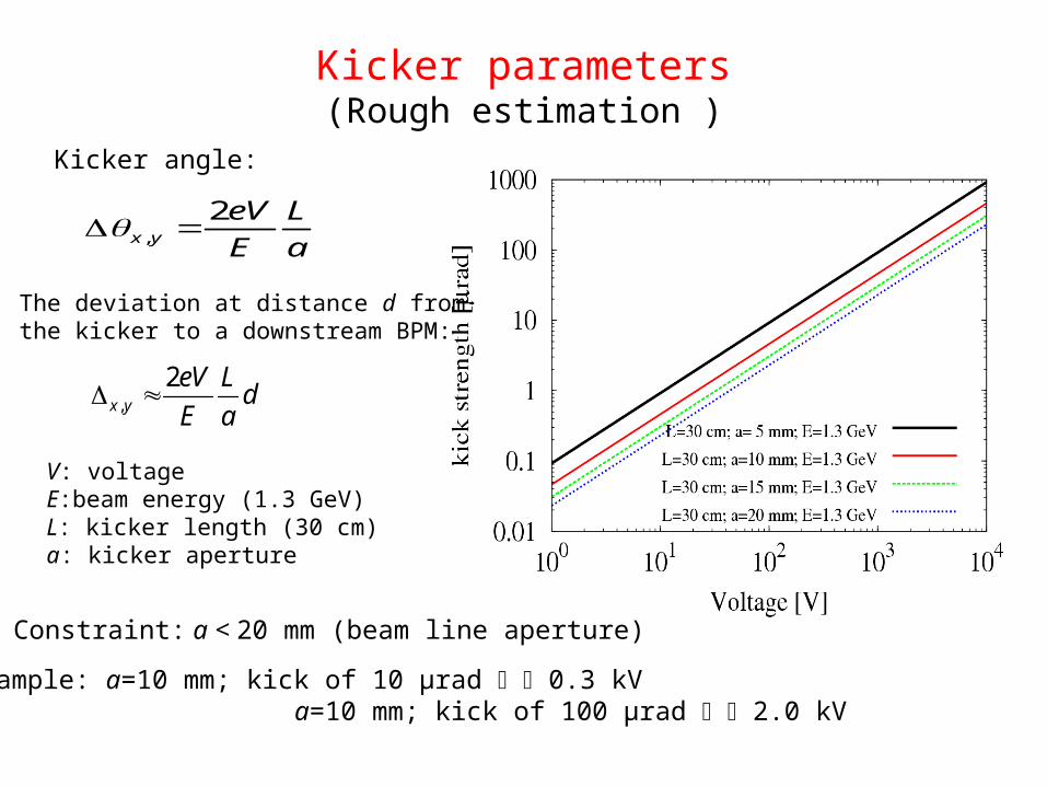
V: voltageE:beam energy (1.3 GeV)L: kicker length (30 cm)a: kicker aperture
Constraint: a < 20 mm (beam line aperture)
For example: a=10 mm; kick of 10 μrad 0.3 kV a=10 mm; kick of 100 μrad 2.0 kV
Kicker angle:
The deviation at distance d from the kicker to a downstream BPM:
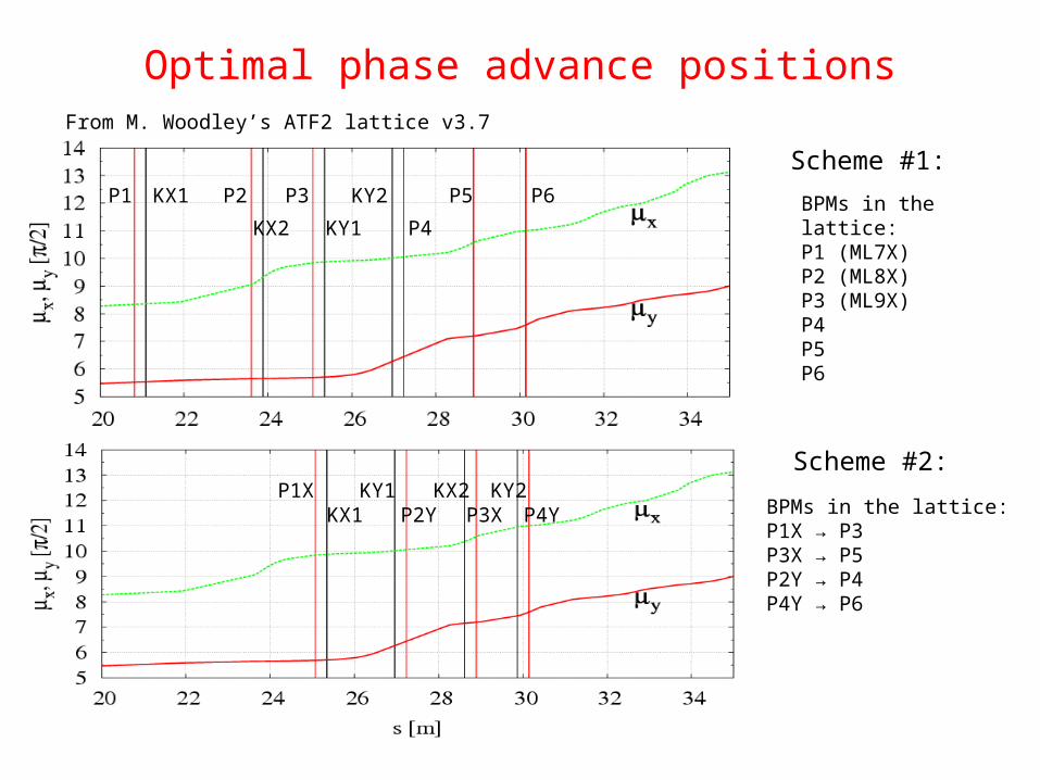
Optimal phase advance positionsFrom M. Woodley’s ATF2 lattice v3.7
BPMs in the lattice: P1 (ML7X)P2 (ML8X)P3 (ML9X)P4 P5P6
Scheme #1:
Scheme #2:
BPMs in the lattice:P1X → P3P3X → P5P2Y → P4P4Y → P6
P1 P2KX1
KX2
P5 P6
P4
P3
KY1
KY2
P1X KX2P3X
KY1P2Y
KY2P4YKX1
Placet based model for ATF2
• Tracking of initial transverse gaussian distribution of 10000 macro-particles– 0.08 % energy spread
– Nominal energy E0=1.3 GeV
– Vertical normalised nominal emittance γεy=3 x 10⁻⁸ mrad
– Horizontal normalised nominal emittance γεy=3 x 10⁻⁶ mrad
• In Placet the correctors are represented as dipoles
• Study of jitter propagation, kicker response in the downstream BPMs
• Possibility to apply ground motion effects (Andrei Seryi’s models) and dynamics corrections
• Steering FF/FB corrections using the FONT kickers and BPMs in progress

Phase advance between kickers(#1 scheme)
Phase advance between kicker pairs of ≈ π/2
≈ π/2
≈ π/2
Orbit jitters in the EXT line
Main sources: extraction kicker errors, energy jitter in DR and residual
dispersion in the EXT line, …
Estimated from measurements in ATF [ATF2 Proposal, Volume 1, pg. 41; M.
Ross et al., ATF-04-05, 2004]:
• x jitter 20 μm (~20 % of the beam size)
• y jitter 2-3.5 μm (~40 % of the beam size)
• x’ jitter 1.0 mrad (? Too big!)
• y’ jitter 2 μrad
Should we use this values as a reference for the ATF2 beam dynamics
simulations ?
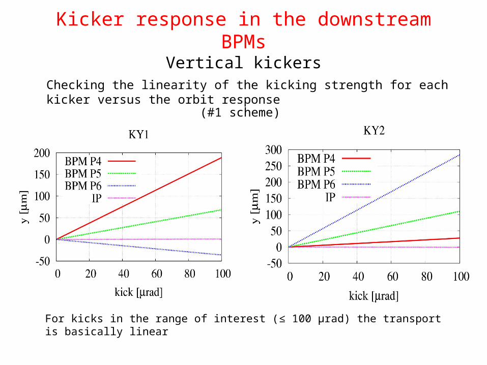
Kicker response in the downstream BPMsVertical kickers
For kicks in the range of interest (≤ 100 μrad) the transport is basically linear
Checking the linearity of the kicking strength for each kicker versus the orbit response
(#1 scheme)
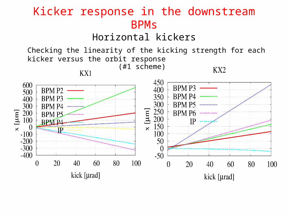
Kicker response in the downstream BPMsHorizontal kickers
Checking the linearity of the kicking strength for each kicker versus the orbit response
(#1 scheme)
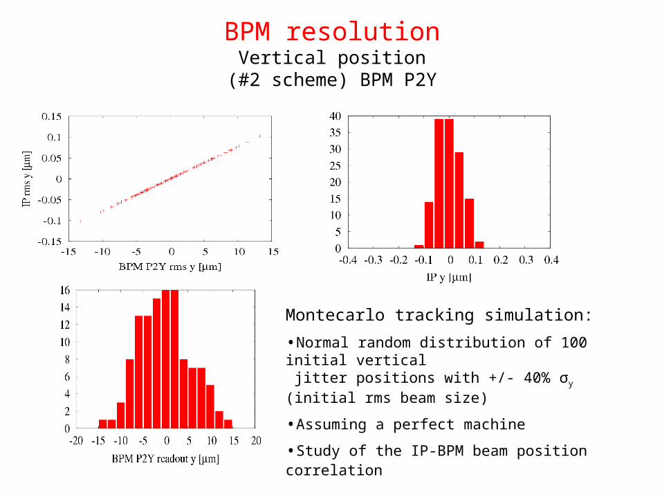
BPM resolutionVertical position
(#2 scheme) BPM P2Y
Montecarlo tracking simulation:
•Normal random distribution of 100 initial vertical jitter positions with +/- 40% σy (initial rms beam size)
•Assuming a perfect machine
•Study of the IP-BPM beam position correlation
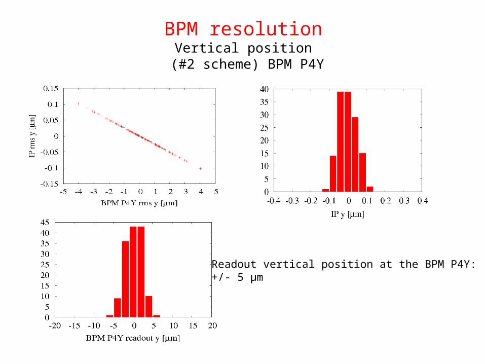
BPM resolutionVertical position
(#2 scheme) BPM P4Y
Readout vertical position at the BPM P4Y:+/- 5 μm
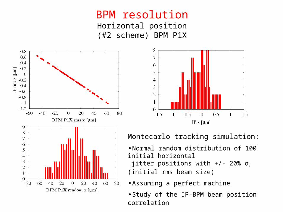
BPM resolutionHorizontal position
(#2 scheme) BPM P1X
Montecarlo tracking simulation:
•Normal random distribution of 100 initial horizontal jitter positions with +/- 20% σx (initial rms beam size)
•Assuming a perfect machine
•Study of the IP-BPM beam position correlation
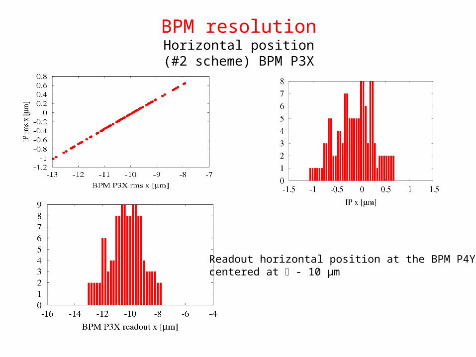
BPM resolutionHorizontal position
(#2 scheme) BPM P3X
Readout horizontal position at the BPM P4Ycentered at - 10 μm
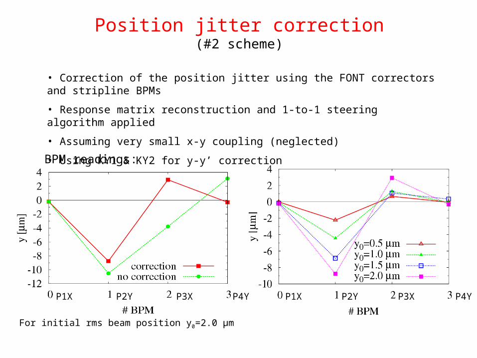
Position jitter correction(#2 scheme)
• Correction of the position jitter using the FONT correctors and stripline BPMs
• Response matrix reconstruction and 1-to-1 steering algorithm applied
• Assuming very small x-y coupling (neglected)
• Using KY1 & KY2 for y-y’ correction BPM readings:
For initial rms beam position y0=2.0 μm
P1X P3XP2Y P4Y P1X P2Y P3X P4Y
Summary and ongoing studies
• Optimal locations have been chosen for the kicker and BPM pairs of the FONT FF/FB system
• The required FONT kicker performance is being studied in order to define a complete mechanical model
• Placet based beam dynamics simulations using a single bunch has been performed: initial jitter propagation, kicker response, residue propagation, position jitter correction
• In the kick range [0-100] μrad the (x,x’) and (y,y’) transports are practically linear
• Multibunch tracking simulation studies are planned to study the performance of the FF/FB system for 20 bunches
• EPAC 2008 paper on FONT @ ATF2 simulations ?