Embed Size (px)
Citation preview
Course Code: ATC00838VEN
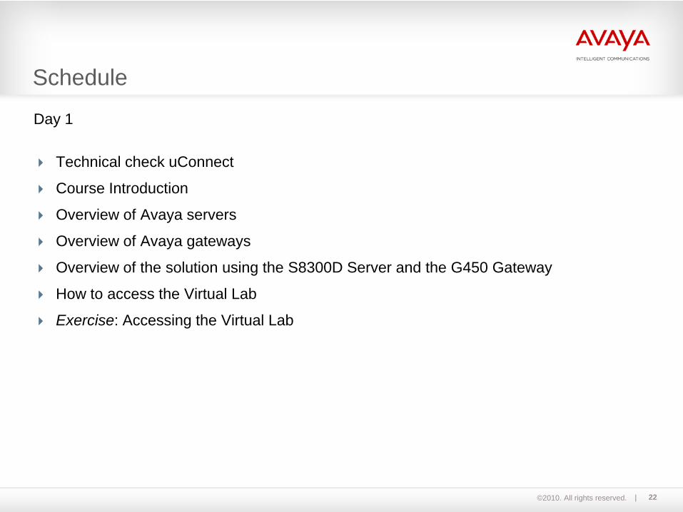
Day 1
Avaya Servers and Gateways Implementation Workshop
©2010. All rights reserved.
Module 01Welcome Introduction
2
©2010. All rights reserved. 3
Is everyone familiar with uConnect?– Yes – No
Familiar with uConnect?
©2010. All rights reserved. 4
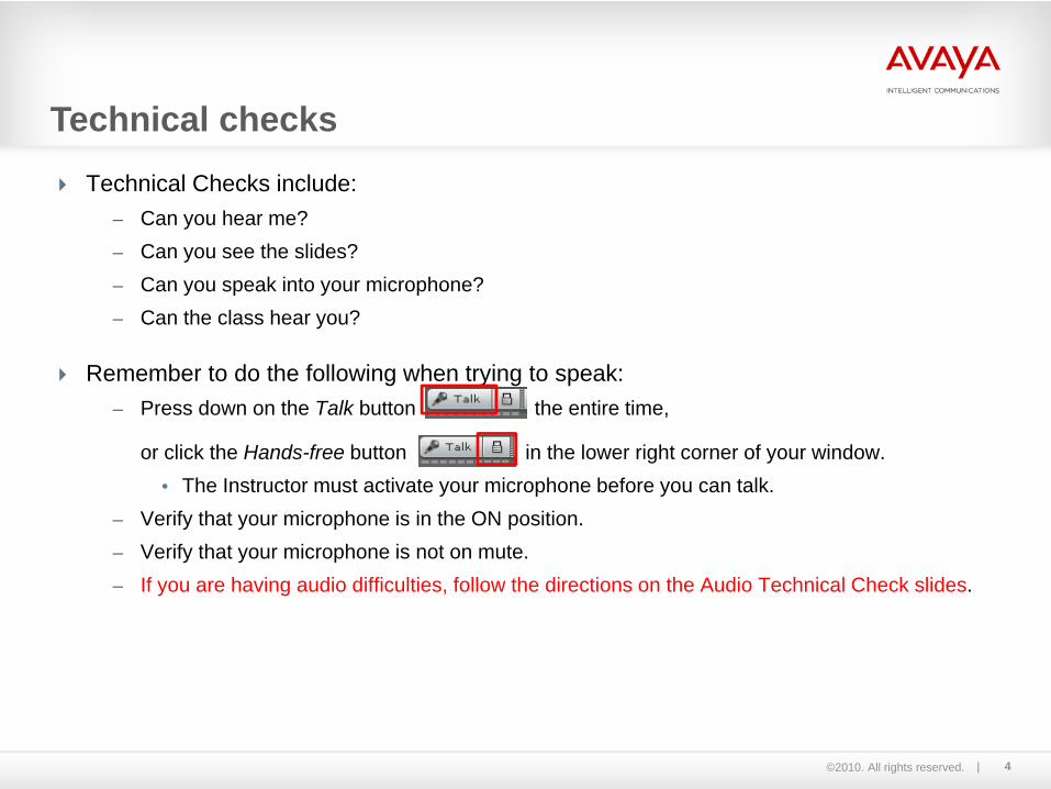
Technical Checks include:– Can you hear me?– Can you see the slides?– Can you speak into your microphone?– Can the class hear you?
Remember to do the following when trying to speak:– Press down on the Talk button the entire time,
or click the Hands-free button in the lower right corner of your window. • The Instructor must activate your microphone before you can talk.
– Verify that your microphone is in the ON position.– Verify that your microphone is not on mute.– If you are having audio difficulties, follow the directions on the Audio Technical Check slides.
Technical checks

©2010. All rights reserved. 5
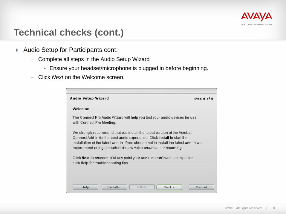
Having problems with Audio?– Follow the Audio Setup for Participants
1. Click Meeting on the navigation bar across the top.2. Click Manage My Settings.3. Click Audio Setup Wizard.4. Complete all steps in the Audio Setup Wizard.
Technical checks (cont.)
©2010. All rights reserved. 6
Audio Setup for Participants cont.– Complete all steps in the Audio Setup Wizard
• Ensure your headset/microphone is plugged in before beginning.– Click Next on the Welcome screen.
Technical checks (cont.)

©2010. All rights reserved. 7
Audio Setup for Participants cont.– Test sound output by clicking Test. If you hear a sound, proceed by clicking Next.
Technical checks (cont.)

©2010. All rights reserved. 8
Audio Setup for Participants cont.– On the Select Microphone screen, select your microphone. If you are not sure which device
to pick, click Next, and Connect Pro will choose for you.
Technical checks (cont.)

©2010. All rights reserved. 9
Audio Setup for Participants cont.– On the Tune Microphone Volume screen, click Allow on the Adobe Flash Player Settings to
begin tuning your ,microphone.
Technical checks (cont.)

©2010. All rights reserved. 10
Audio Setup for Participants cont.– Ensure that your microphone is not muted and click Record. Read the sentence into the
microphone. Click Stop once you are done. Then click Play to hear the recording.
Technical checks (cont.)

©2010. All rights reserved. 11
Audio Setup for Participants cont.– On the Tune Silence Level screen, to detect the amount of background noise around you,
click Test Silence.
Technical checks (cont.)

©2010. All rights reserved. 12
Audio Setup for Participants cont.– The Finished! Screen appears. If you are still having problems, click Help or manually set
your audio settings by clicking Advanced Settings.
Technical checks (cont.)
©2010. All rights reserved. 13
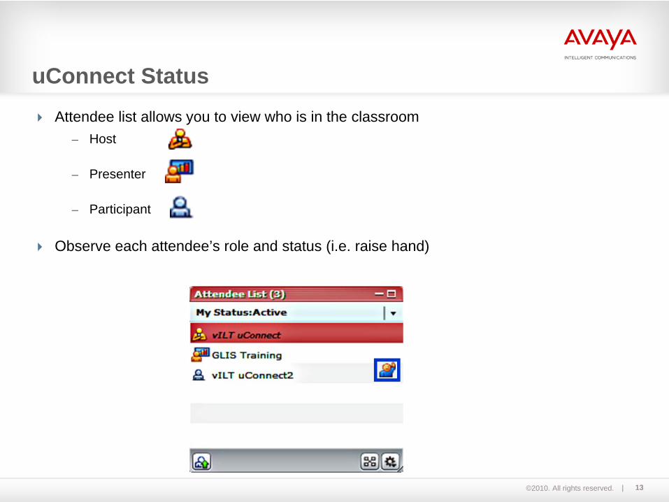
Attendee list allows you to view who is in the classroom– Host
– Presenter
– Participant
Observe each attendee’s role and status (i.e. raise hand)
uConnect Status

©2010. All rights reserved. 14
Change status using the Menu Bar or the My Status icon
For questions, use the raise hand status change and wait for the instructor to prompt you to ask your question via chat, computer microphone, or audio bridge
uConnect Status (cont.)
©2010. All rights reserved. 15
Before we begin, let‘s discuss some ground rules and uConnect protocols for our session:– Relax and be yourself.– Participate actively.– Keep our discussions on task.
Ground Rules?

©2010. All rights reserved. 16
Introduce yourself– Name– Experience– What would you like to get out of this course?
Getting to Know You?

©2010. All rights reserved.
Questions Before We Begin ?
17

©2010. All rights reserved. 18
Module 02Course Objectives and Schedule

©2010. All rights reserved. 19
This module will provide you with an agenda for the seminar and information on the associated learning objectives.
The course has been prepared for customers, business partners, and Avaya employees that are responsible for configuring the Avaya Aura™ Communication Manager.
You will learn how to configure the current server and gateway hardware by doing practical virtual exercises.
Course Objectives
©2010. All rights reserved. 20
After participating in this course, you will be able toConfigure a solution comprising a S8300D Server and G450 Gateway Configure a solution comprising a S8800 Simplex Server acting in Processor Ethernet mode and a G450 Gateway Configure a solution comprising a S8800 Duplex Server and G650 Gateway Implement Communication Manager (CM) Messaging Configure a local survivable processor (LSP) Discuss new software for IP phones Use the official Avaya documentation to gather more information
Course Objectives (cont.)

©2010. All rights reserved. 2121
The scope for this workshop includes;– Installation of Communication Manager– Installation of Communication Manager Messaging– Discussion of various Avaya Aura™ components
The scope does NOT include a discussion of other Aura™ components including:– SIP Enablement Server– Application Enablement Server– Session Manager– System Manager– SIP Phones– etc.
Course Scope
©2010. All rights reserved. 22
Day 1
Technical check uConnect
Course Introduction
Overview of Avaya servers
Overview of Avaya gateways
Overview of the solution using the S8300D Server and the G450 Gateway
How to access the Virtual Lab
Exercise: Accessing the Virtual Lab
Schedule

©2010. All rights reserved. 23
Day 2
Configuring the G450 Gateway
Installing Communication Manager on the S8300D Server
Configuring the S8300D Server
Overview of Avaya Site Administration
Configuring Softphones
Exercise: Configuring S8300D with G450 in all lab systems
Discuss IP phones with HTTP(S) server
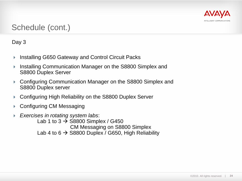
Schedule (cont.)
©2010. All rights reserved. 24
Day 3
Installing G650 Gateway and Control Circuit Packs
Installing Communication Manager on the S8800 Simplex and S8800 Duplex Server
Configuring Communication Manager on the S8800 Simplex and S8800 Duplex server
Configuring High Reliability on the S8800 Duplex Server
Configuring CM Messaging
Exercises in rotating system labs:Lab 1 to 3 S8800 Simplex / G450
CM Messaging on S8800 SimplexLab 4 to 6 S8800 Duplex / G650, High Reliability
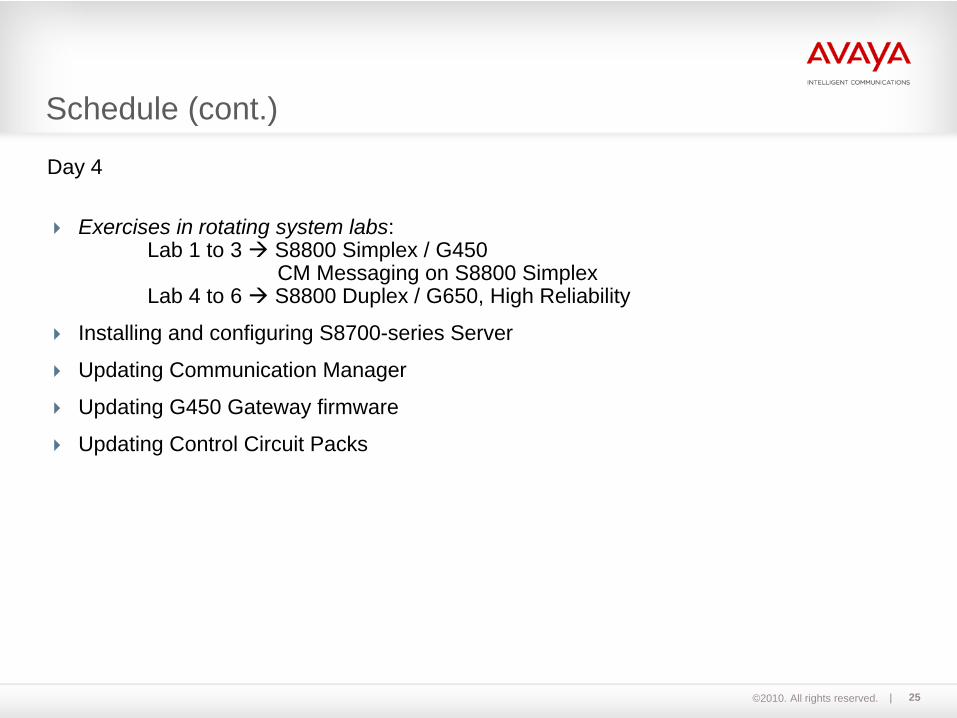
Schedule (cont.)
©2010. All rights reserved. 25
Day 4
Exercises in rotating system labs:Lab 1 to 3 S8800 Simplex / G450
CM Messaging on S8800 SimplexLab 4 to 6 S8800 Duplex / G650, High Reliability
Installing and configuring S8700-series Server
Updating Communication Manager
Updating G450 Gateway firmware
Updating Control Circuit Packs
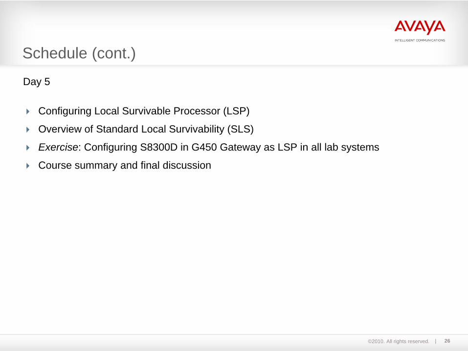
Schedule (cont.)
©2010. All rights reserved. 26
Day 5
Configuring Local Survivable Processor (LSP)
Overview of Standard Local Survivability (SLS)
Exercise: Configuring S8300D in G450 Gateway as LSP in all lab systems
Course summary and final discussion
Schedule (cont.)

©2010. All rights reserved. 27
S8300D
G450
S8300D
G450
S8300D
G450
ICC/LSP
ICC/LSP
ICC/LSP
S8800
G450
S8800
G450
S8800
Lab 1
Lab 2
Lab 3
G450
Switch
Switch
Switch
Lab setup system 1 to 3
©2010. All rights reserved. 28
Switch SwitchS8800 S8800
Switch SwitchS8300D
G450
S8300D
G450
S8300D
G450
ICC/LSP
ICC/LSP
ICC/LSP
G650
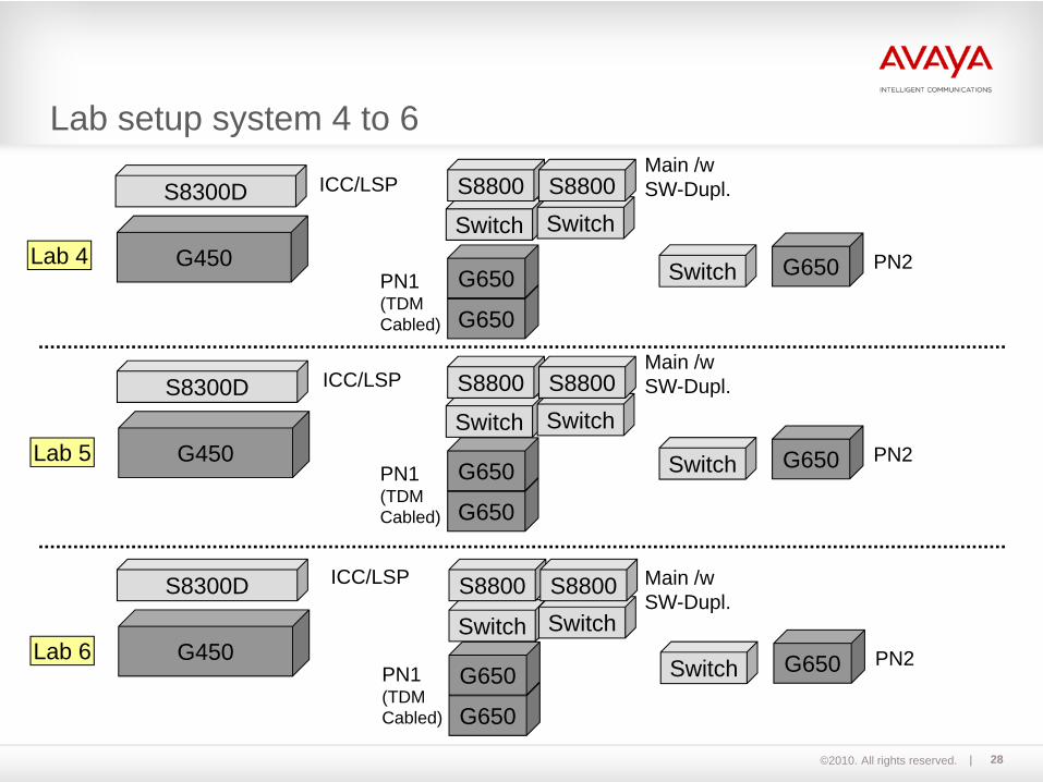
Lab 4
Lab 5
Lab 6
S8800
G650
Main /w SW-Dupl.
PN1(TDMCabled)
PN2
Main /w SW-Dupl.
G650
S8800
Switch
G650
G650PN1(TDMCabled)
PN2G650 Switch
G650
G650 PN2G650 Switch
Switch SwitchS8800
Main /w SW-Dupl.S8800
Lab setup system 4 to 6
PN1(TDMCabled)

©2010. All rights reserved. 29
Section 1- System setup for lab 1 to 6 S8300D/G450
Section 2 (with rotation)
- System setup for lab 1 to 3 S8800 Simplex/G450 S8800 Simplex with CM Messaging
- System setup for lab 4 to 6 S8800 Duplex/G650High Reliability
Section 3- System setup for lab 1 to 6 S8300D as LSP
Lab Setup
©2010. All rights reserved. 30
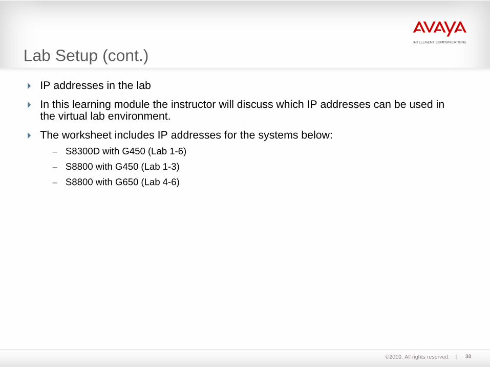
IP addresses in the lab
In this learning module the instructor will discuss which IP addresses can be used in the virtual lab environment.
The worksheet includes IP addresses for the systems below: – S8300D with G450 (Lab 1-6)– S8800 with G450 (Lab 1-3)– S8800 with G650 (Lab 4-6)
Lab Setup (cont.)

©2010. All rights reserved. 31
Module 03Avaya Aura™ OverviewLecture
©2010. All rights reserved. 32
S8500C serverUpon successful completion of this module, you should be able to:- Describe the advantages of Avaya Aura™- Distinguish between the different core components of Avaya Aura™
Avaya Server Overview

©2010. All rights reserved. 33
What is Avaya Aura™ ?
Avaya Aura™ is a next-generation unified communications solution introduced by Avaya in March 2009.
Avaya Aura™ eliminates the complexity and cost of integrating and managing devices, systems, applications and infrastructure from many vendors.
Avaya Aura™ gives business users rapid, easy access to the applications they need whatever their location, access device or network is.
©2010. All rights reserved. 34
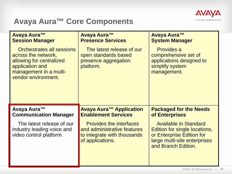
Avaya Aura™ Core ComponentsAvaya Aura™ Session Manager
Orchestrates all sessions across the network, allowing for centralized application and management in a multi-vendor environment.
Avaya Aura™ Presence Services
The latest release of our open standards based presence aggregation platform.
Avaya Aura™System Manager
Provides a comprehensive set of applications designed to simplify system management.
Avaya Aura™ Communication Manager
The latest release of our industry leading voice and video control platform.
Avaya Aura™ Application Enablement Services
Provides the interfaces and administrative features to integrate with thousands of applications.
Packaged for the Needs of Enterprises
Available in Standard Edition for single locations, or Enterprise Edition for large multi-site enterprises and Branch Edition.
©2010. All rights reserved. 35
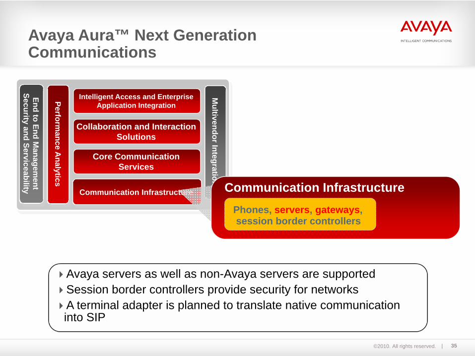
Avaya servers as well as non-Avaya servers are supportedSession border controllers provide security for networksA terminal adapter is planned to translate native communication into SIP
Intelligent Access and Enterprise Application Integration
Collaboration and Interaction Solutions
Core Communication Services
Communication Infrastructure
Performance A
nalytics
End to End Managem
ent Security and Serviceability
Multivendor Integration
Communication InfrastructurePhones, servers, gateways,session border controllers
Avaya Aura™ Next Generation Communications
©2010. All rights reserved. 36
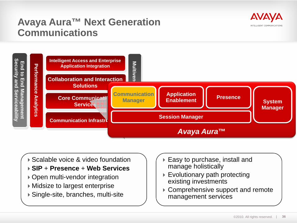
Scalable voice & video foundationSIP + Presence + Web ServicesOpen multi-vendor integrationMidsize to largest enterpriseSingle-site, branches, multi-site
Easy to purchase, install andmanage holisticallyEvolutionary path protectingexisting investmentsComprehensive support and remote management services
Intelligent Access and Enterprise Application Integration
Collaboration and Interaction Solutions
Core Communication Services
Communication Infrastructure
Performance A
nalytics
End to End Managem
ent Security and Serviceability
Multivendor Integration
Avaya <New Name>Avaya Aura™
Communication Manager System
Manager
ApplicationEnablement Presence
Session Manager
Avaya Aura™ Next Generation Communications

©2010. All rights reserved. 37
Module 04Avaya Server OverviewLecture
©2010. All rights reserved. 38
S8500C serverUpon successful completion of this module, you should be able to:- Describe the key functionalities of the different servers of Avaya Aura™ Communication
Manager. - List the different types of Avaya Servers- Distinguish between an Internal Call Controller and an External Call Controller
Avaya Server Overview
©2010. All rights reserved. 39
S8500C serverAvaya IP telephone solutions consist of Avaya servers, media gateways, Ethernet switches, and communication devices. With Avaya’s flexible, modular architecture and the use of standards-based hardware and software, the possible combinations are almost limitless.In order to provide companies with the highest degree of flexibility, the server and gateway components of the Communication Manager applications family can be used modularly, in any combination. A number of user-defined configurations can be deployed to fulfill a wide range of company requirements, from a single site to a complex, multinational, convergent network that is able to support more than 100,000 voice and data users with several servers.
Avaya Server Overview (cont.)
©2010. All rights reserved. 40
S8500C serverAvaya’s range of servers provide a robust application platform that works with operating systems based on industry standards to support distributed IP networking and centralized call handling in multi-protocol networks. These servers are available with other servers as integrated solutions but can also work independently.Avaya servers offer the following features:
- Redundant, survivable call processing and media processing contribute to crucial business continuity.
- Standards-based computing supports the Linux operating systems and Avaya Aura™ Communication Manager.
- Distributed failsafe IP networking supports campus, global multi-site, and branch environments.
Avaya Server Overview (Cont.)
©2010. All rights reserved. 41
Servers that support Avaya telephony solutions include:- S8300B/C/D server - S8400 server- S8500-series server- S8710 with DAL2, S8720, S8730 server
- S8800 Simplex, S8800 Duplex server
Additional documentation:- Avaya Aura™ Communication Manager Hardware Description and Reference- Latest Communication Manager Software & Firmware Compatibility Matrix
Avaya Server Overview (Cont.)
©2010. All rights reserved. 42
Internal Call Controller (ICC) - ICC servers are designed to fit within a gateway.- S8300 servers slip into a H.248 media gateway.- S8400 servers slide into an IPSI controlled gateway such as G650.
External Call Controllers (ECC) - ECC servers are self-contained within their own cabinet.- S8800, S8700-, and S8500-series servers are considered to be ECCs.
Avaya Servers are sometimes characterized by their type of chassis:
©2010. All rights reserved. 43
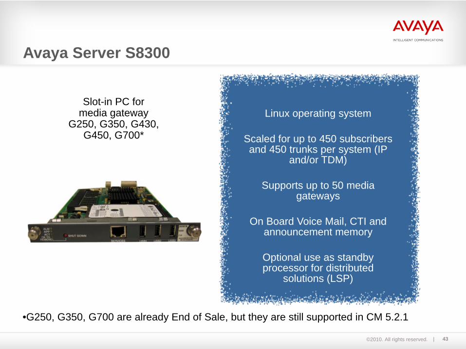
Linux operating system
Scaled for up to 450 subscribers and 450 trunks per system (IP
and/or TDM)
Supports up to 50 media gateways
On Board Voice Mail, CTI and announcement memory
Optional use as standby processor for distributed
solutions (LSP)
Slot-in PC for media gateway
G250, G350, G430,G450, G700*
•G250, G350, G700 are already End of Sale, but they are still supported in CM 5.2.1
Avaya Server S8300
©2010. All rights reserved. 44
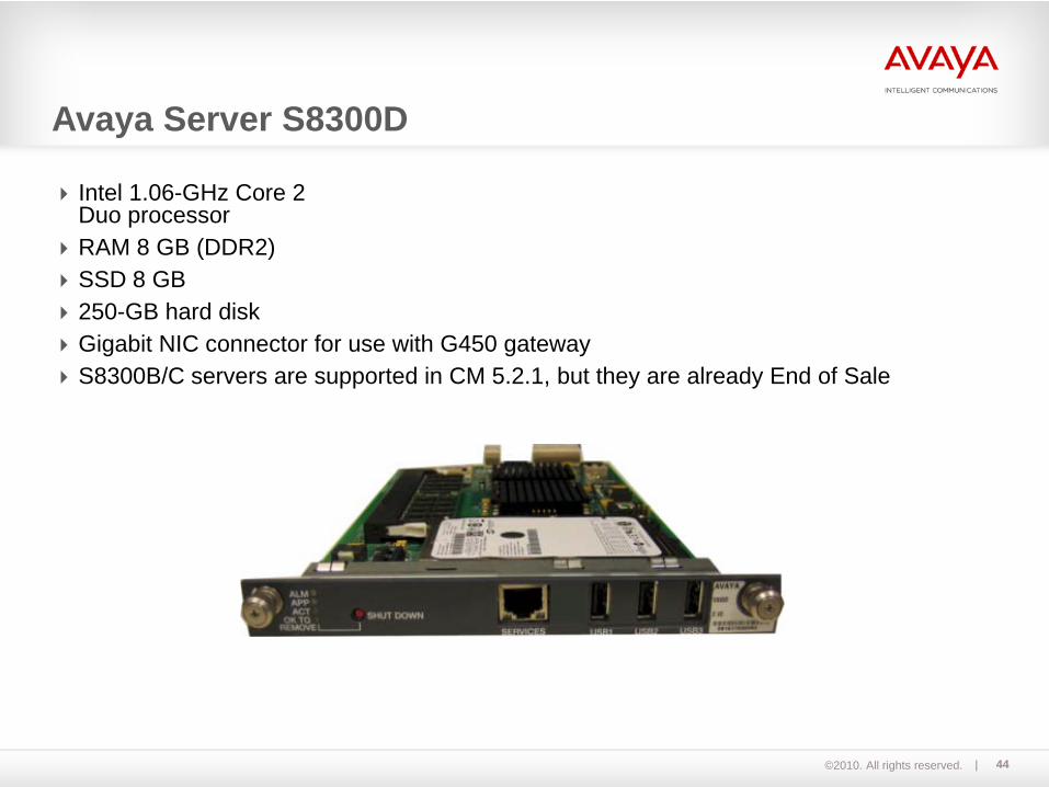
Intel 1.06-GHz Core 2 Duo processorRAM 8 GB (DDR2)SSD 8 GB250-GB hard diskGigabit NIC connector for use with G450 gatewayS8300B/C servers are supported in CM 5.2.1, but they are already End of Sale
Avaya Server S8300D
©2010. All rights reserved. 45
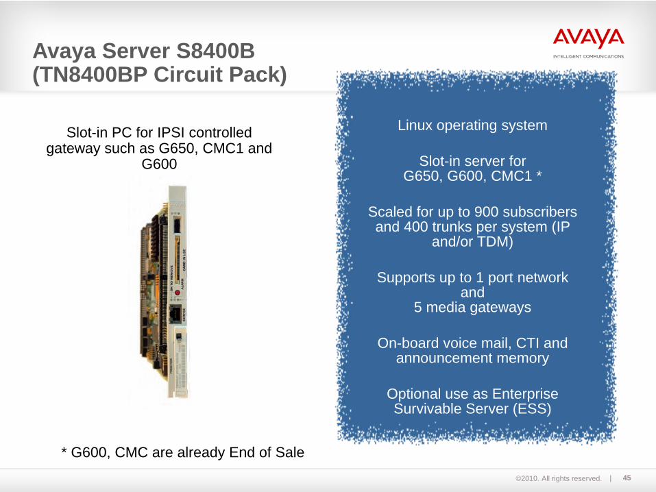
Linux operating system
Slot-in server for G650, G600, CMC1 *
Scaled for up to 900 subscribers and 400 trunks per system (IP
and/or TDM)
Supports up to 1 port network and
5 media gateways
On-board voice mail, CTI and announcement memory
Optional use as Enterprise Survivable Server (ESS)
Slot-in PC for IPSI controlled gateway such as G650, CMC1 and
G600
* G600, CMC are already End of Sale
Avaya Server S8400B(TN8400BP Circuit Pack)
©2010. All rights reserved. 46
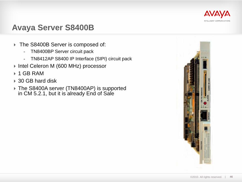
The S8400B Server is composed of:- TN8400BP Server circuit pack- TN8412AP S8400 IP Interface (SIPI) circuit pack
Intel Celeron M (600 MHz) processor1 GB RAM30 GB hard diskThe S8400A server (TN8400AP) is supportedin CM 5.2.1, but it is already End of Sale
Avaya Server S8400B
©2010. All rights reserved. 47
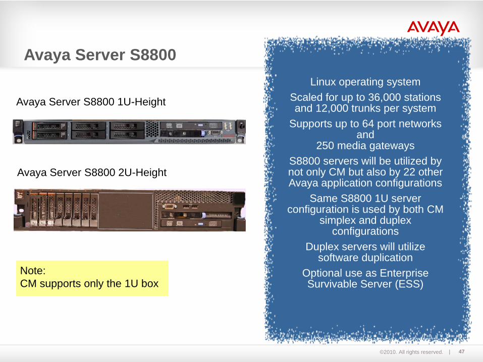
Linux operating systemScaled for up to 36,000 stations and 12,000 trunks per system
Supports up to 64 port networks and
250 media gatewaysS8800 servers will be utilized by not only CM but also by 22 other Avaya application configurations
Same S8800 1U server configuration is used by both CM
simplex and duplex configurations
Duplex servers will utilize software duplication
Optional use as Enterprise Survivable Server (ESS)
Avaya Server S8800 1U-Height
Avaya Server S8800 2U-Height
Note:CM supports only the 1U box
Avaya Server S8800

©2010. All rights reserved. 48
Quad core Intel I7 “Nehalem” Processor, 2.26 GHz4 GB of DRAM Utilizes a RAID 1 disk array consisting of 2 each SAS 10K 146-GB disk drives (RAID 5 and RAID 10 configurable)2 each Gigabit Ethernet NICs on motherboard, 2 each Gigabit Ethernet NICs on daughterboard (if needed), 2 additional Gigabit Ethernet NICs on PCI board if neededOptional: Redundant power supply
S8800 for CM Simplex Configuration
S8800 for CM Duplex Configuration
1U
1U
1USoftwareDuplication
Avaya Server S8800 (cont.)

©2010. All rights reserved. 49
IBM x3550m2 platformAll standard S8800 features previously listedSix 2.5-inch hot-swap SAS or hot-swap SATA hard disk drive baysSupports two PCI risers:
- Slot 1 supports low-profile cards (PCI Express Gen2 x16 or PCI-X 1.0a 64-bit/133 MHz ).- Slot 2 supports half-length, full-height cards (PCI Express Gen2 x16 or PCI-X 1.0a 64-bit/133
MHz).Six dual-motor hot-swap fans.Form Factor: 1UHeight x length x depth: 1.7" x 17.3" x 28.0" (43 mm x 440 mm x 711 mm) Weight: 34 lbs (15.4 kg ) when fully configured
S8800 1U Unique Configuration

©2010. All rights reserved. 50
S8800 2U Unique Configuration
IBM x3650m2 platformAll standard S8800 features previously listedEight 2.5-inch hot-swap SAS or hot-swap SATA hard disk drive baysSupports two PCI riser slots:
- Each riser supports:- Two 133 MHz/64-bit PCI-X 1.0a slots- One PCI Express x16 (x16 lanes)
Three hot-swap fans.Form factor: 2UHeight x length x depth: 3.346" x 17.465" x 28.701" (82.5 mm x 443.6 mm x 729 mm) Weight: 64 lbs. (29.03 kg. ) when fully configured
©2010. All rights reserved. 51
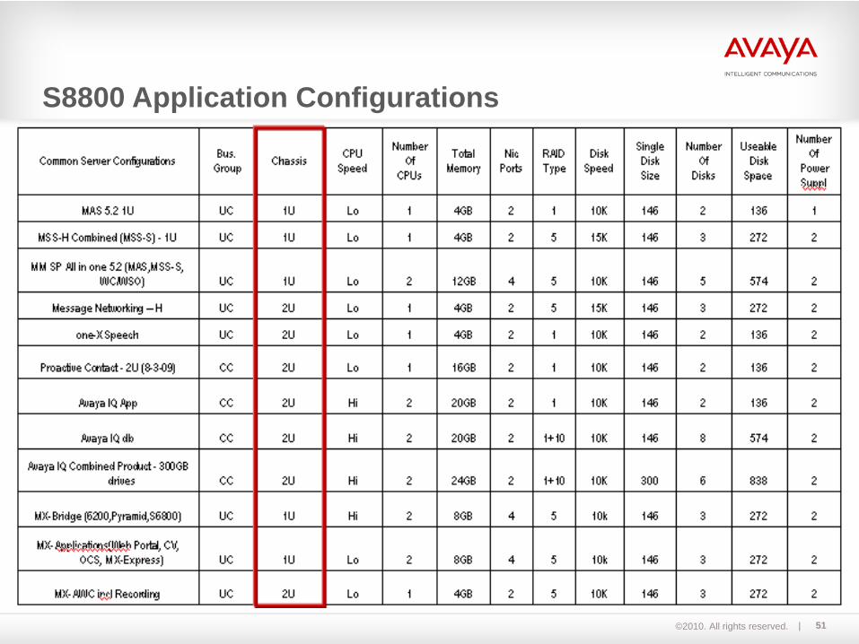
S8800 Application Configurations
©2010. All rights reserved. 52
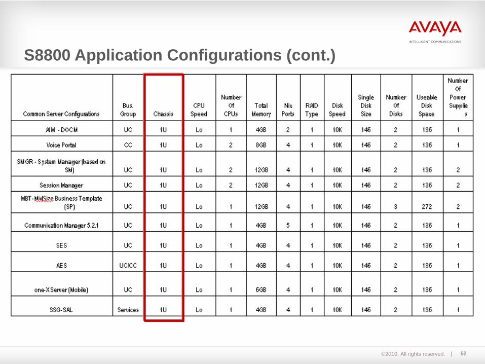
S8800 Application Configurations (cont.)
©2010. All rights reserved. 53
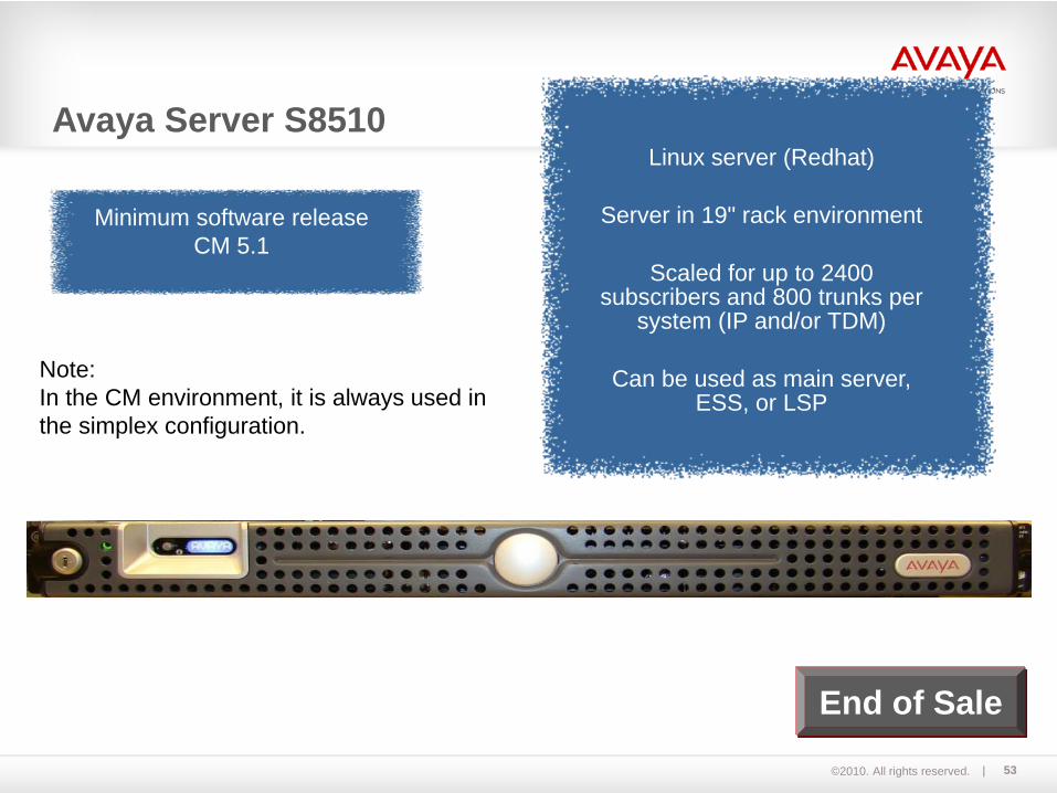
Linux server (Redhat)
Server in 19" rack environment
Scaled for up to 2400 subscribers and 800 trunks per
system (IP and/or TDM)
Can be used as main server, ESS, or LSP
Minimum software releaseCM 5.1
End of Sale
Note:In the CM environment, it is always used in the simplex configuration.
Avaya Server S8510

©2010. All rights reserved. 54
Simplex server – 19" construction, 1 height unit2 GB RAM, expandable to 32 GB (4 GB RAM needed for Communication Manager Express)2 X 250GB SATA HDDRedundant Hot-Pluggable HDD RAID-14 X Intel 5335 2GHz (Quad-Core)Controls up to 64 port networksControls up to 250 H.248 media gateways or 250 LSPSupports G650, G700, G450, G430, G350, and G250 media gatewaysSupports G600, CMC1, SCC1, and MCC1 media gateways in migrationsOptional Ethernet processor
S8500C server
End of Sale
Avaya Server S8510 (cont.)
©2010. All rights reserved. 55
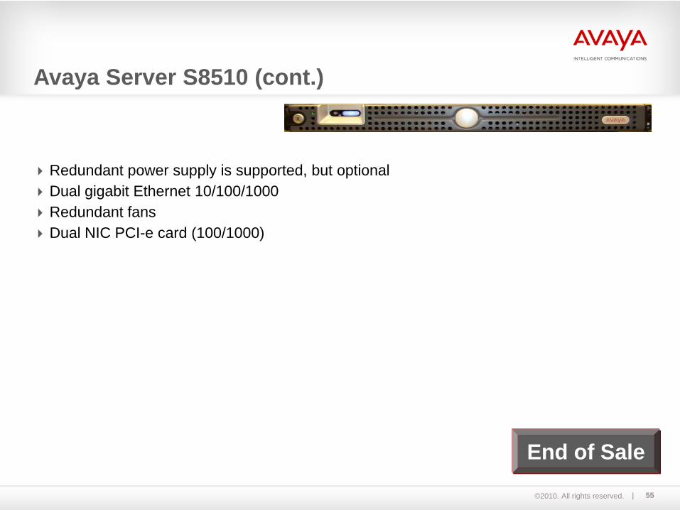
Redundant power supply is supported, but optionalDual gigabit Ethernet 10/100/1000Redundant fansDual NIC PCI-e card (100/1000)
S8500C server
End of Sale
Avaya Server S8510 (cont.)

©2010. All rights reserved. 56
Linux server (Redhat)Server in 19" rack
environmentScaled for up to 2400
subscribers and 800 trunks per system (IP and/or TDM)
100,000 busy hour call completions (BHCC)
Avaya Server S8500C
Linux server (Redhat)
Server in 19" rack environment
Scaled for up to 2400 subscribers and 800 trunks per
system (IP and/or TDM)
Can be used as main server, ESS, or LSP
Note:In the CM environment, it is always used in the simplex configuration.
End of Sale
Avaya Server S8500C
©2010. All rights reserved. 57
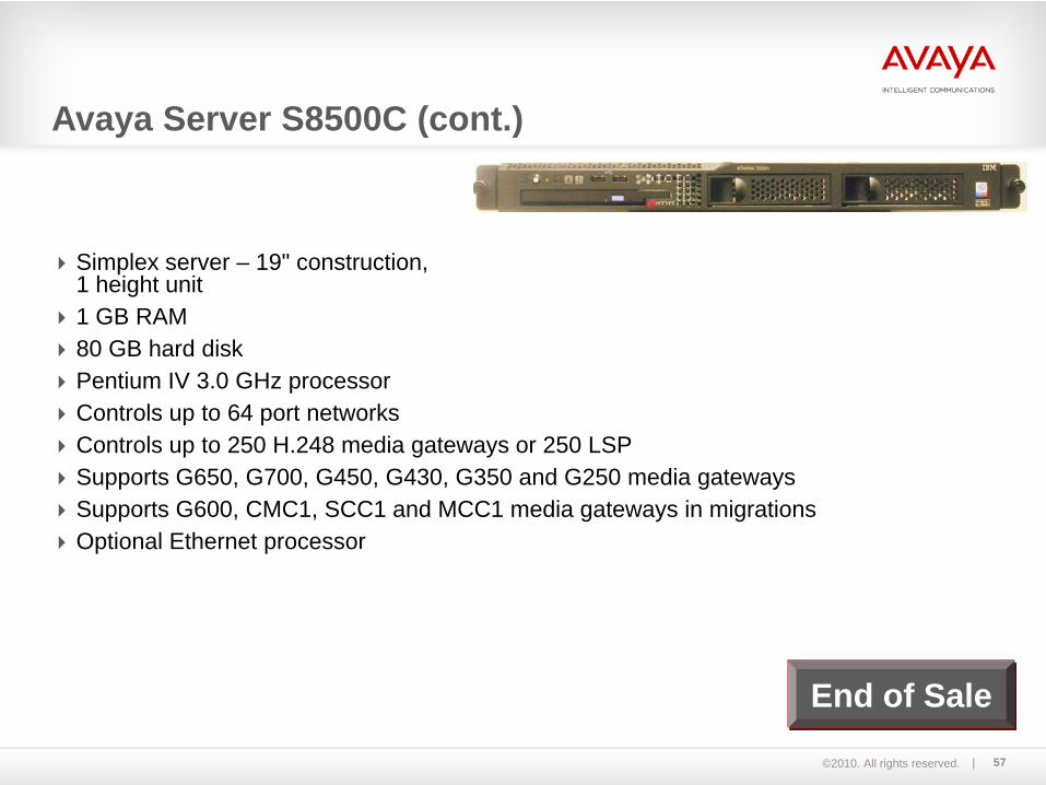
Simplex server – 19" construction, 1 height unit1 GB RAM80 GB hard diskPentium IV 3.0 GHz processorControls up to 64 port networksControls up to 250 H.248 media gateways or 250 LSPSupports G650, G700, G450, G430, G350 and G250 media gatewaysSupports G600, CMC1, SCC1 and MCC1 media gateways in migrationsOptional Ethernet processor
S8500C server
Avaya Server S8500C (cont.)
End of Sale

©2010. All rights reserved. 58
Duplicated (fault tolerant) signaling server on Linux
19" technologyScaled for up to 36,000 subscribers
(12,000 IP terminals)on a single server
Up to 64 interconnected port networks possible
Up to 250 gateways per serverCan be used as main server
or ESS
Note:In the CM environment, it is always used in the duplex configuration.
Avaya Server S8730
End of Sale
©2010. All rights reserved. 59
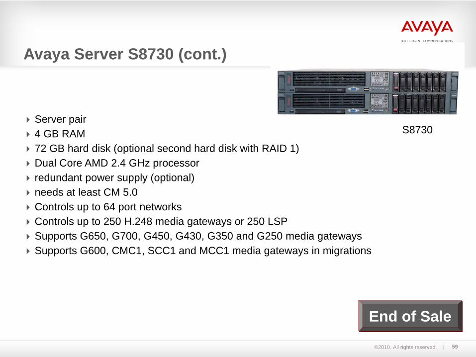
S8730Server pair4 GB RAM72 GB hard disk (optional second hard disk with RAID 1)Dual Core AMD 2.4 GHz processorredundant power supply (optional)needs at least CM 5.0Controls up to 64 port networksControls up to 250 H.248 media gateways or 250 LSPSupports G650, G700, G450, G430, G350 and G250 media gatewaysSupports G600, CMC1, SCC1 and MCC1 media gateways in migrations
Avaya Server S8730 (cont.)
End of Sale

©2010. All rights reserved. 60
S8700 S8710 S8720 (XL) S8730
Processor Pent. III, 850 MHz
Intel Xeon, 3.06 GHz
AMD Opteron 2.4 GHz
AMD Dual Core 2.4 GHz
RAM 256 MB +256 MB DAJ1
512 MB +256 MB DAL1
1GB+256 MB DAL1 (512MB DAL2)
4GB +512MB DAL2
Hard disk 40 GB 72 GB SCSI 72 GB SCSI 72 GB SAS (opt. RAID1)
Duplication card DAJ1 (33 MHz)
DAL1 (33 MHz)
DAL1 (33 MHz)DAL2 (100 MHz)
DAL2 (100 MHz)
HW duplication X X X X
SW duplication X X
Max. stations 36.000 36.000 36.000 36.000
Max. IP devices 12.000 12.000 12.000 12.000
Max. trunks 8.000 8.000 8.000 (12.000) 12.000
Port networks 64 64 64 64
H.248 gateways/LSPs 250 250 250 250
BHCC 300.000 375.000 375.000 (600.000) 600.000
Avaya S8700-series Server

©2010. All rights reserved. 61
Date Launched Minimum CM Rel.
Maximum CM Rel.
Notes
S8300 May 2002 MV 1.1 CM 2.0 End of Sale
S8300B Dec 2003 CM 2.0 CM 5.2.1 End of Sale
S8300C Mar 2007 CM 4.0 CM 5.2.1 End of Sale
S8300D Nov 2009 CM 5.2.1S8400 May 2006 CM 3.1 CM 5.2.1 End of Sale
S8500A Dec 2003 CM 2.0 CM 4.0.5 End of Sale
S8500B Mar 2005 CM 2.2 CM 5.2.1 End of Sale
S8500C Jun 2006 CM 3.1.2 CM 5.2.1 End of Sale
S8510 Jun 2008 CM 5.1S8700 May 2002 MV 1.1 CM 4.0.5 End of Sale
S8710 Jan 2005 CM 2.2 CM 5.2.1 End of Sale
S8720 Feb 2006 CM 3.1 CM 5.2.1 End of Sale
S8730 Jan 2008 CM 5.0 CM 5.2.1 End of Sale
S8800 Nov 2009 CM 5.2.1
Avaya Servers – Minimum/ Maximum software version
©2010. All rights reserved. 62
Module 05Avaya Gateway OverviewLecture
©2010. All rights reserved. 63
Media Gateway OverviewUpon successful completion of this module, you should be able to:
- Describe the key functionalities of the different gateways of Avaya Aura™ Communication Manager.
- List the different types of Avaya Media Gateways

©2010. All rights reserved. 64
Media Gateway Overview (cont.)Avaya media gateways connect to an Avaya server, either directly or indirectly through other media gateways.Avaya media gateways are stackable, modular hardware elements. They deliver data, voice, fax, video, and messaging functionalities to your network. Avaya media gateways support both bearer and signaling traffic, which are transmitted between packet-switched and circuit-switched networks. These gateways are optimized for corporate telephony applications. Avaya media gateways can be used very flexibly, in 100% IP environments or in mixed setups with IP and TDM.

©2010. All rights reserved. 65
Media Gateway Overview (Cont.)Avaya gateways provide several functions:
Connectivity between the IP network and non-packetized devices and interfaces, supporting a variety of trunks and analog/digital endpoints Conferencing capabilities Call treatments on the edge, which is a unique Avaya capability that can provide announcements and music on hold
The important survivability differentiator is that all the gateway functions are stillavailable if a branch or office becomes isolated from the network. A Survivable Server must be reachable to provide this functionality.
©2010. All rights reserved. 66
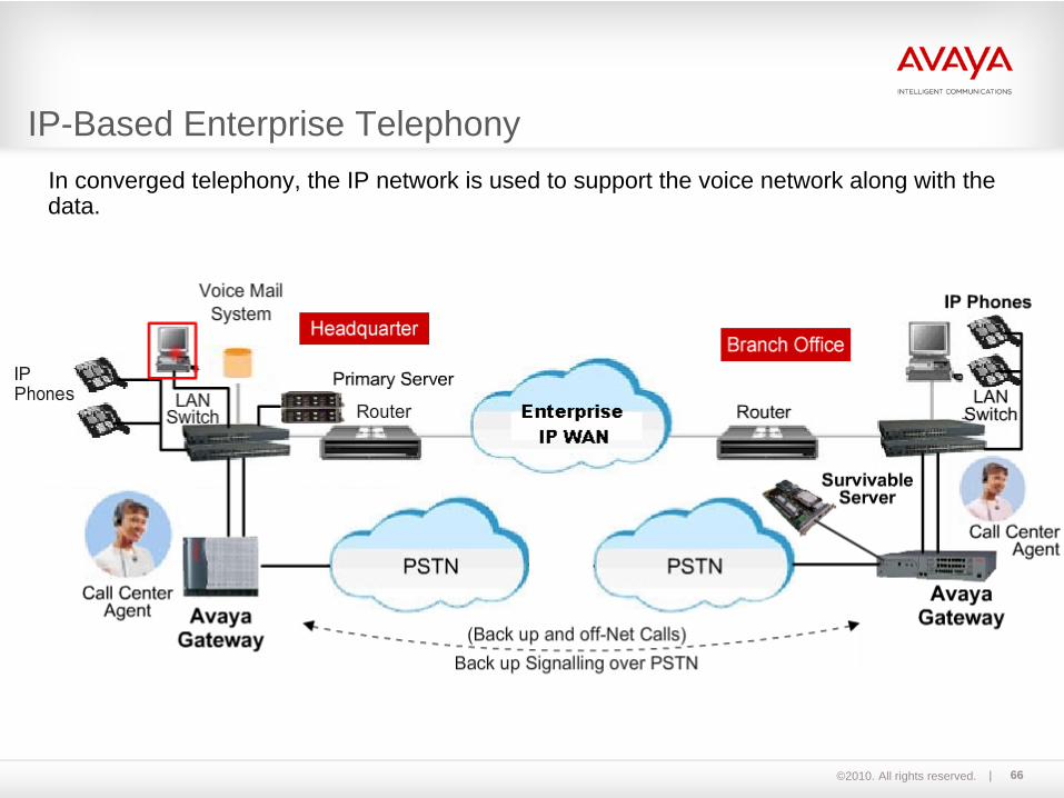
IP-Based Enterprise TelephonyIn converged telephony, the IP network is used to support the voice network along with the data.
©2010. All rights reserved. 67
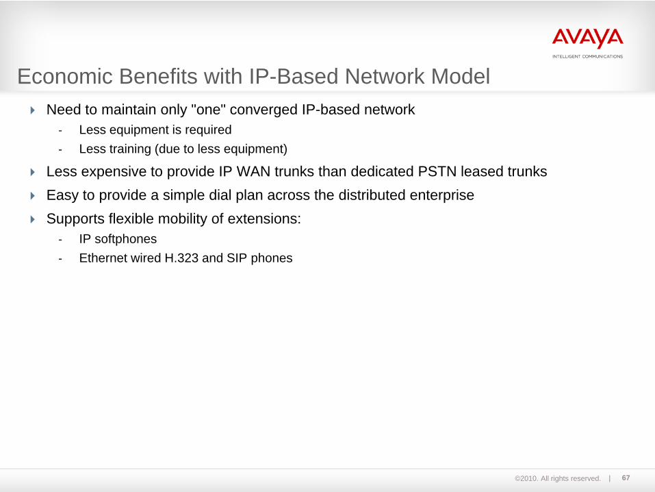
Economic Benefits with IP-Based Network ModelNeed to maintain only "one" converged IP-based network
- Less equipment is required- Less training (due to less equipment)
Less expensive to provide IP WAN trunks than dedicated PSTN leased trunksEasy to provide a simple dial plan across the distributed enterpriseSupports flexible mobility of extensions:
- IP softphones- Ethernet wired H.323 and SIP phones

©2010. All rights reserved. 68
Media Services Provided over IP NetworksVoice-over-IP (supported by codecs for G.711, G.729, G.726, etc.)
Fax-over-IP (T.38 Relay, Proprietary Pass-Thru, Proprietary Relay)
Modem-over-IP (Proprietary Pass-Thru, Proprietary Relay)

©2010. All rights reserved. 69
Headquarters Communication FunctionalityPrimary (main) server supports Avaya Aura Communication Manager (CM) to provide voice feature management
Messaging server
Conference server
Call Center application server(s)
Larger Gateway (may support a few hundred to several thousand calls)- Serve HQ stations (both legacy and IP)- Provide PSTN trunk access- Manage signaling and VOIP bearer stream conversion for traffic to branch office
gateways
Survivability Options:- ESS- LSP- SLS
©2010. All rights reserved. 70
Branch Office Communication FunctionalityTypical size is bounded by less than 400 clients
Served by a product called a gateway
A gateway provides the following services:– Direct support of legacy (analog and DCP) stations– Indirect support of co-located IP phones (see DSP resources)– Direct support of trunks for local PSTN access– DSP (Digital Signal Processing) resources provided for:
• Generation of call progress tones (dial tone, ringing, busy, intercept, etc.)• Detection of tones• Music-On-Hold• Announcements• Conferencing
– Survivability options:• ESS• LSP server blade• SLS (built-in software)

©2010. All rights reserved. 71
Gateways are divided based on their functionality:H.248 gateways
IPSI controlled media gateway
SIP gateways
Gateway Functionality

©2010. All rights reserved. 72
Examples of each gateway type are:
H.248 Gateways IPSI controlledMedia Gateways SIP Gateway
G430G450G150 *G250 *G350*G700 *G150 *
G650G600 *
Multi Carrier Cabinets *(MCC)
Single Carrier Cabinets *(SCC)
Prologix/Definity 1 *
G860AudioCodes SIP Media Gateway
* Already End of Sale
©2010. All rights reserved. 73
Avaya has certain protocols based on the gateway configuration:Time Division Multiplexing (TDM)Analog protocol Avaya proprietary Digital Communications Protocol (DCP)Transmission Control Protocol/Internet Protocol (TCP/IP) Session Initiation Protocol (SIP)
Gateway Protocols
©2010. All rights reserved. 74
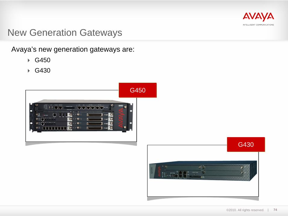
Avaya’s new generation gateways are:G450G430
G450
G430
New Generation Gateways
©2010. All rights reserved. 75
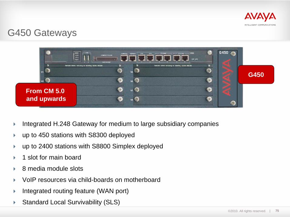
Integrated H.248 Gateway for medium to large subsidiary companies
up to 450 stations with S8300 deployed
up to 2400 stations with S8800 Simplex deployed
1 slot for main board
8 media module slots
VoIP resources via child-boards on motherboard
Integrated routing feature (WAN port)
Standard Local Survivability (SLS)
G450
From CM 5.0 and upwards
G450 Gateways
©2010. All rights reserved. 76
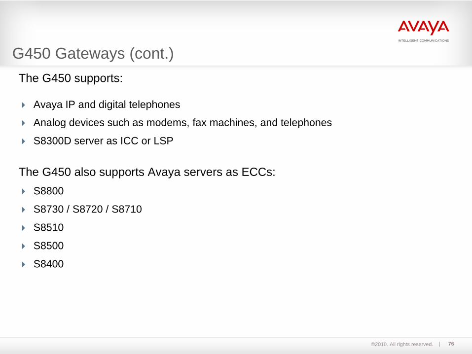
The G450 supports:
Avaya IP and digital telephones
Analog devices such as modems, fax machines, and telephones
S8300D server as ICC or LSP
The G450 also supports Avaya servers as ECCs:S8800
S8730 / S8720 / S8710
S8510
S8500
S8400
G450 Gateways (cont.)
©2010. All rights reserved. 77
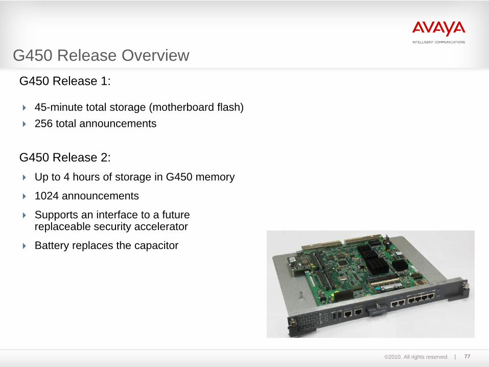
G450 Release 1:
45-minute total storage (motherboard flash)256 total announcements
G450 Release 2:Up to 4 hours of storage in G450 memory
1024 announcements
Supports an interface to a future replaceable security accelerator
Battery replaces the capacitor
G450 Release Overview

©2010. All rights reserved. 78
The Avaya G430:Is a multipurpose gateway
Delivers intelligent communications to enterprises of all sizes
Supports one S8300D server in slot V1
Useful for small and medium branches of 2 to 150 users
Hardware– 1 main chassis (G430)– Up to 2 expansion chassis
(EM 200)
25 DSP resources (expandable to 100) withCommunication Manager Release 5.2.1 orlater.
G430 MG
G430 Overview

©2010. All rights reserved. 79
G430 Overview (cont.)
©2010. All rights reserved. 80
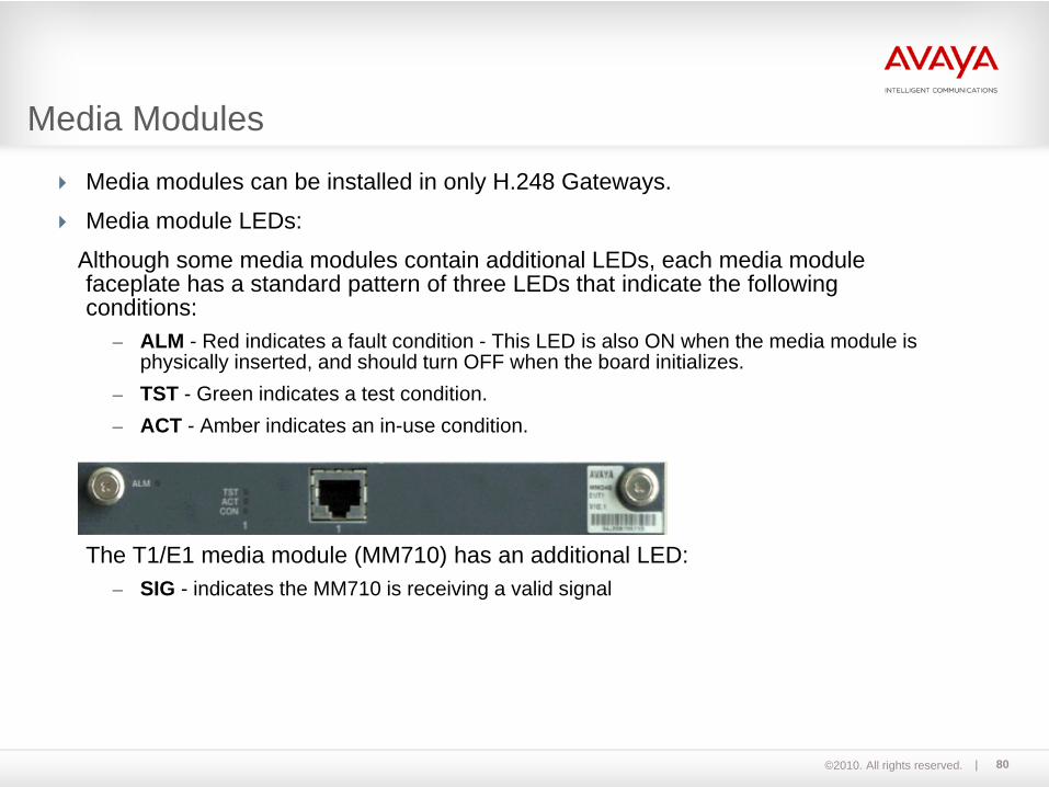
Media modules can be installed in only H.248 Gateways.
Media module LEDs:
Although some media modules contain additional LEDs, each media module faceplate has a standard pattern of three LEDs that indicate the following conditions:
– ALM - Red indicates a fault condition - This LED is also ON when the media module is physically inserted, and should turn OFF when the board initializes.
– TST - Green indicates a test condition.– ACT - Amber indicates an in-use condition.
The T1/E1 media module (MM710) has an additional LED:– SIG - indicates the MM710 is receiving a valid signal
Media Modules

©2010. All rights reserved. 81
MM712
The MM712 DCP media module provides eight DCP telephone ports. These portssupport 2-wire DCP telephones.
The MM712 can be exchanged while in operation.
The media module shown here is only an example.All available media modules are in the
hardware manual.
Media Modules (cont.)
©2010. All rights reserved. 82
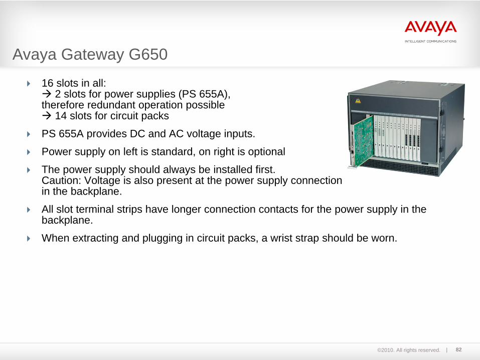
16 slots in all:2 slots for power supplies (PS 655A),
therefore redundant operation possible14 slots for circuit packs
PS 655A provides DC and AC voltage inputs.
Power supply on left is standard, on right is optional
The power supply should always be installed first.Caution: Voltage is also present at the power supply connectionin the backplane.
All slot terminal strips have longer connection contacts for the power supply in the backplane.
When extracting and plugging in circuit packs, a wrist strap should be worn.
Avaya Gateway G650
©2010. All rights reserved. 83
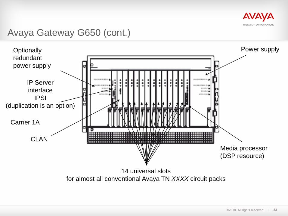
Optionallyredundantpower supply
Power supply
IP Serverinterface
IPSI(duplication is an option)
CLANMedia processor(DSP resource)
14 universal slotsfor almost all conventional Avaya TN XXXX circuit packs
Carrier 1A
Avaya Gateway G650 (cont.)
©2010. All rights reserved. 84
The architectures for the S8800 server use an entity called a port network (PN).
A PN uses combinations of gateways to provide physical ports and interfaces for handling calls.
A port network can be one of the following:– One single-carrier G650 Gateway– A stack of single-carrier G650 Gateways that are connected with a TDM bus cable and
share connections to the server or port circuit packs
The G450 and G430 Gateways are controlled by a Communication Manager server via H.248 and are not considered port networks.
What is a Port Network?

©2010. All rights reserved. 85
Connectivity between G650s:– A maximum of five G650 can be stacked per port network.– To connect G650s, a dedicated extended TDM/LAN cable is
required.– Carrier address range from A to E.
Connectivity between PNs:– Fiber-PNC*
TN570D, TN2305B or TN2306B is required.– IP-PNC
TN2302AP or TN2602AP is required.
Connectivity between Server and PN– Control network between PNs and server.– Optionally control network can be duplicated.– Duplicated TN2312BP IPSIs.
One in Carrier A, another in Carrier B.
G650 connections
* Already End of Sale
©2010. All rights reserved. 86
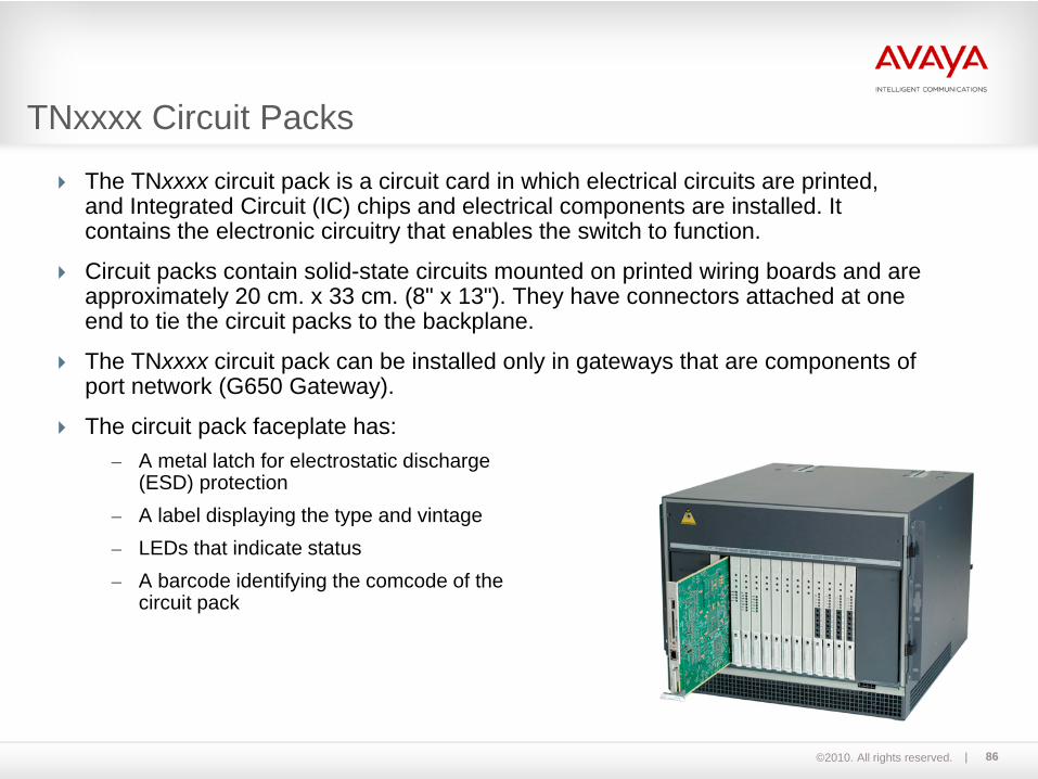
The TNxxxx circuit pack is a circuit card in which electrical circuits are printed, and Integrated Circuit (IC) chips and electrical components are installed. It contains the electronic circuitry that enables the switch to function.
Circuit packs contain solid-state circuits mounted on printed wiring boards and are approximately 20 cm. x 33 cm. (8" x 13"). They have connectors attached at one end to tie the circuit packs to the backplane.
The TNxxxx circuit pack can be installed only in gateways that are components of port network (G650 Gateway).
The circuit pack faceplate has:– A metal latch for electrostatic discharge
(ESD) protection– A label displaying the type and vintage– LEDs that indicate status– A barcode identifying the comcode of the
circuit pack
TNxxxx Circuit Packs

©2010. All rights reserved. 87
LEDs on the circuit pack faceplate indicate the following conditions:
– Red – Alarm: A failure has been detected on the pack.
– Green – Test: The system is running a test on the pack.
– Amber – Busy: The circuit pack is in use; removal will cause services interruption.
TNxxxx Circuit Packs - LEDs
©2010. All rights reserved. 88
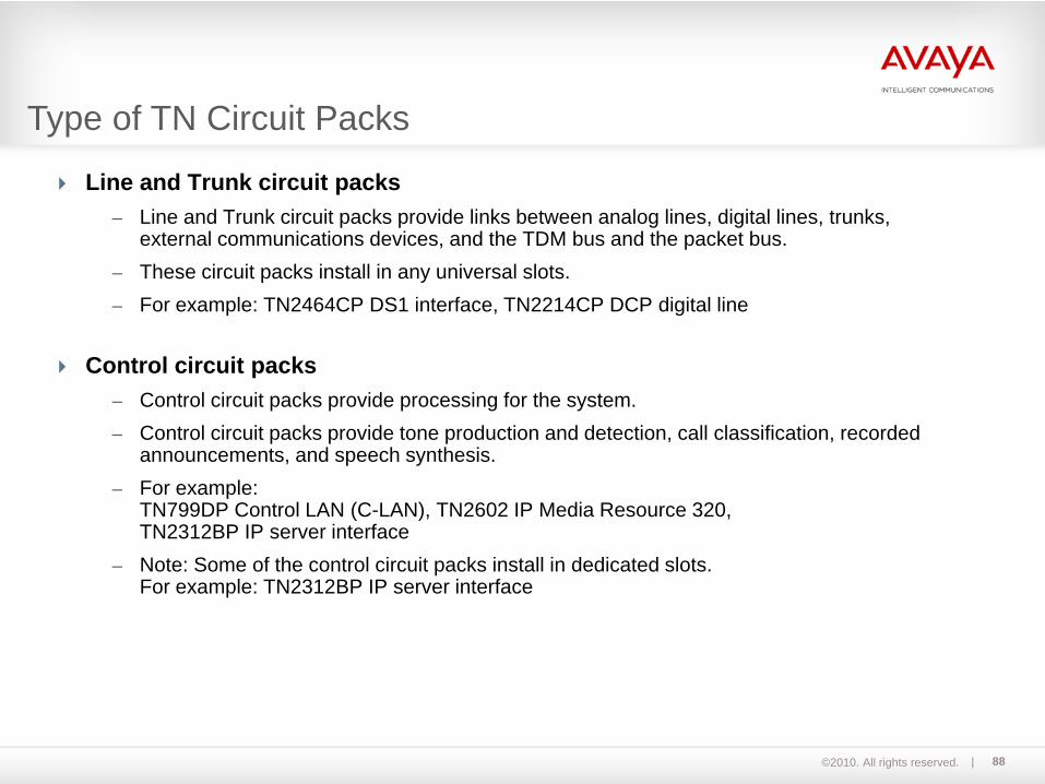
Line and Trunk circuit packs – Line and Trunk circuit packs provide links between analog lines, digital lines, trunks,
external communications devices, and the TDM bus and the packet bus. – These circuit packs install in any universal slots. – For example: TN2464CP DS1 interface, TN2214CP DCP digital line
Control circuit packs – Control circuit packs provide processing for the system. – Control circuit packs provide tone production and detection, call classification, recorded
announcements, and speech synthesis.– For example:
TN799DP Control LAN (C-LAN), TN2602 IP Media Resource 320,TN2312BP IP server interface
– Note: Some of the control circuit packs install in dedicated slots.For example: TN2312BP IP server interface
Type of TN Circuit Packs
©2010. All rights reserved. 89
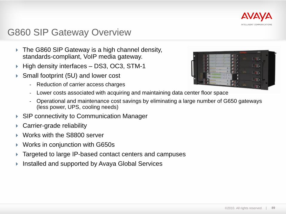
The G860 SIP Gateway is a high channel density, standards-compliant, VoIP media gateway.High density interfaces – DS3, OC3, STM-1Small footprint (5U) and lower cost
- Reduction of carrier access charges - Lower costs associated with acquiring and maintaining data center floor space- Operational and maintenance cost savings by eliminating a large number of G650 gateways
(less power, UPS, cooling needs)
SIP connectivity to Communication ManagerCarrier-grade reliabilityWorks with the S8800 serverWorks in conjunction with G650sTargeted to large IP-based contact centers and campuses Installed and supported by Avaya Global Services
G860 SIP Gateway Overview
©2010. All rights reserved. 90
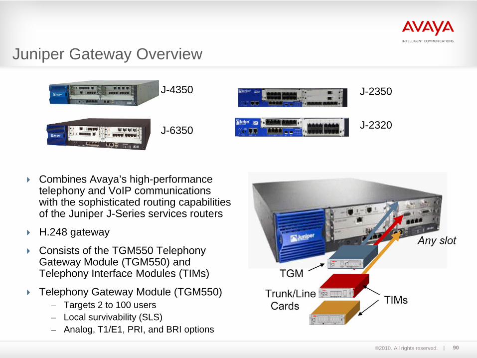
Combines Avaya’s high-performancetelephony and VoIP communicationswith the sophisticated routing capabilitiesof the Juniper J-Series services routers
H.248 gateway
Consists of the TGM550 Telephony Gateway Module (TGM550) and Telephony Interface Modules (TIMs)
Telephony Gateway Module (TGM550)– Targets 2 to 100 users– Local survivability (SLS)– Analog, T1/E1, PRI, and BRI options
J-4350
J-6350
J-2350
J-2320
Juniper Gateway Overview
©2010. All rights reserved. 91
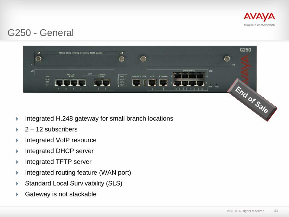
Integrated H.248 gateway for small branch locations
2 – 12 subscribers
Integrated VoIP resource
Integrated DHCP server
Integrated TFTP server
Integrated routing feature (WAN port)
Standard Local Survivability (SLS)
Gateway is not stackable
G250 - General

©2010. All rights reserved. 92
4 analog trunk ports
2 analog lines
8 PoE LAN ports for IP telephones
Support for 2 media modules:- MM 340 T1/E1 data WAN- MM 342 USP data WAN
Integrated VoIP module with 10 resources(G.711, G.729, G.723)
Contact Closure Adjunct (CCA)for potential-free contact
Console port for programming via V.24
G250 Analog

©2010. All rights reserved. 93
2 ISDN exchange line ports (BRI)
1 analog trunk port 2 analog lines
8 PoE LAN ports for IP telephones
Support for 2 media modules:- MM 340 T1/E1 data WAN- MM 342 USP data WAN
Integrated VoIP module with 10 resources(G.711, G.729, G.723)
Contact Closure Adjunct (CCA)for potential-free contact
Console port for programming via V.24
G250 BRI
©2010. All rights reserved. 94
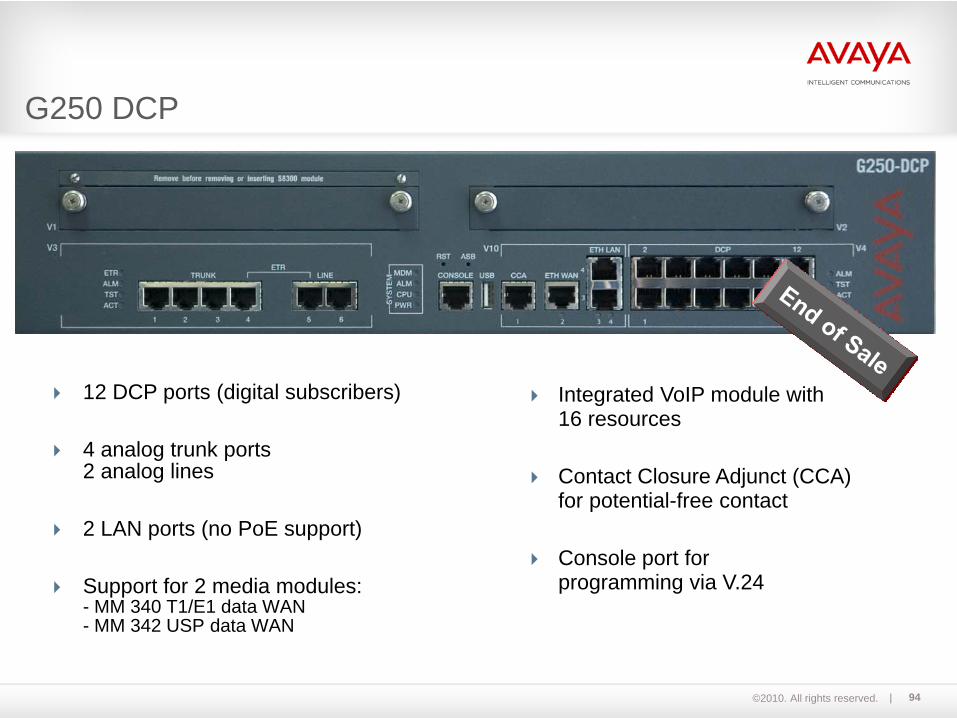
12 DCP ports (digital subscribers)
4 analog trunk ports 2 analog lines
2 LAN ports (no PoE support)
Support for 2 media modules:- MM 340 T1/E1 data WAN- MM 342 USP data WAN
Integrated VoIP module with 16 resources
Contact Closure Adjunct (CCA)for potential-free contact
Console port for programming via V.24
G250 DCP

©2010. All rights reserved. 95
1 T1/E1 port (PRI)
1 analog trunk port 2 analog lines
8 PoE LAN ports for IP telephones
Support for 2 media modules:- MM 340 T1/E1 data WAN- MM 342 USP data WAN
Integrated VoIP module with 16 resources
Contact Closure Adjunct (CCA)for potential-free contact
Console port for programming via V.24
G250 DS1
©2010. All rights reserved. 96
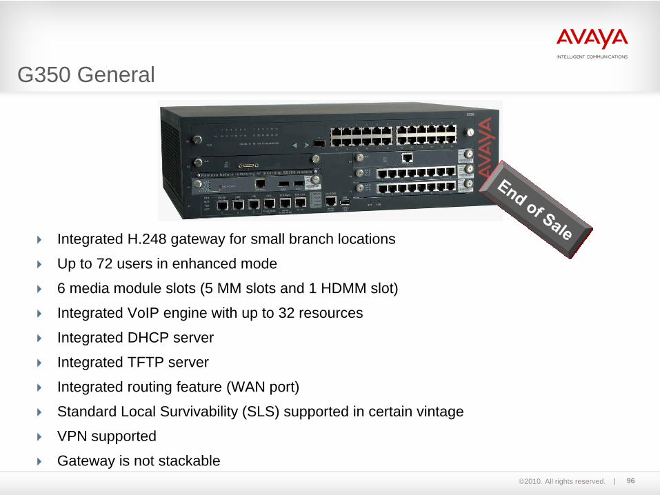
Integrated H.248 gateway for small branch locations
Up to 72 users in enhanced mode
6 media module slots (5 MM slots and 1 HDMM slot)
Integrated VoIP engine with up to 32 resources
Integrated DHCP server
Integrated TFTP server
Integrated routing feature (WAN port)
Standard Local Survivability (SLS) supported in certain vintage
VPN supported
Gateway is not stackable
G350 General
©2010. All rights reserved. 97
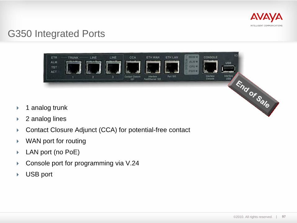
1 analog trunk
2 analog lines
Contact Closure Adjunct (CCA) for potential-free contact
WAN port for routing
LAN port (no PoE)
Console port for programming via V.24
USB port
G350 Integrated Ports

©2010. All rights reserved. 98
The MM314 is permitted only for the media gateway G350 (V6 slot).
The MM314 LAN media module has 24 Ethernet 10/100 base-T access ports with in-line PoE (Power over Ethernet).
The MM314 CANNOT be exchanged while in operation.
The media module shown here is only an example.All available media modules are in the hardware manual.
MM314
Media Modules for G350
©2010. All rights reserved. 99
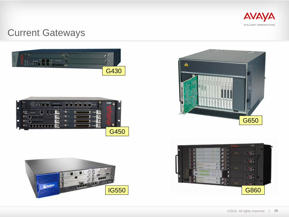
G430
G450
G860
G650
IG550
Current Gateways
©2010. All rights reserved. 100
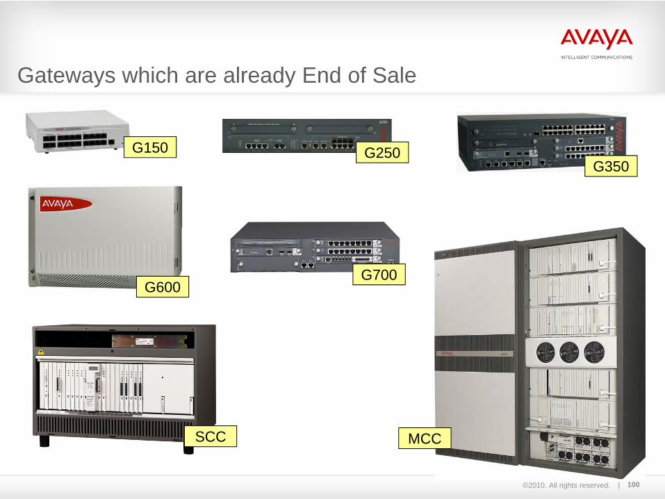
G150
G700
MCC
G600
SCC
G250G350
Gateways which are already End of Sale
©2010. All rights reserved. 101
Module 06S8300D Server with G450 Media GatewayLecture
©2010. All rights reserved. 102
S8500C media server
Upon successful completion of this module, you should be able to:Mount the G450 Gateway in a rack.Replace a Field Replaceable Unit of the G450 Gateway.Describe the Port Addressing of the G450 Gateway.
For more information on programming the G450 Media Gateway, see the following English-language documentation:
Installing and Upgrading the Avaya G450 Media GatewayAvaya Aura™ Communication Manager Hardware Description and ReferenceAvaya G450 CLI ReferenceReplacing the Field Replaceable Units (FRUs) for the Avaya G450 Media Gateway
S8300D with G450 (all labs)

©2010. All rights reserved. 103
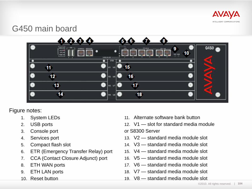
G450 main board
Components of G450
Server
Media Module slots V2 to V8
©2010. All rights reserved. 104
G450 main board
Figure notes:1. System LEDs2. USB ports3. Console port4. Services port5. Compact flash slot6. ETR (Emergency Transfer Relay) port7. CCA (Contact Closure Adjunct) port8. ETH WAN ports9. ETH LAN ports10. Reset button
11. Alternate software bank button12. V1 — slot for standard media moduleor S8300 Server13. V2 — standard media module slot14. V3 — standard media module slot15. V4 — standard media module slot16. V5 — standard media module slot17. V6 — standard media module slot18. V7 — standard media module slot19. V8 — standard media module slot

©2010. All rights reserved. 105
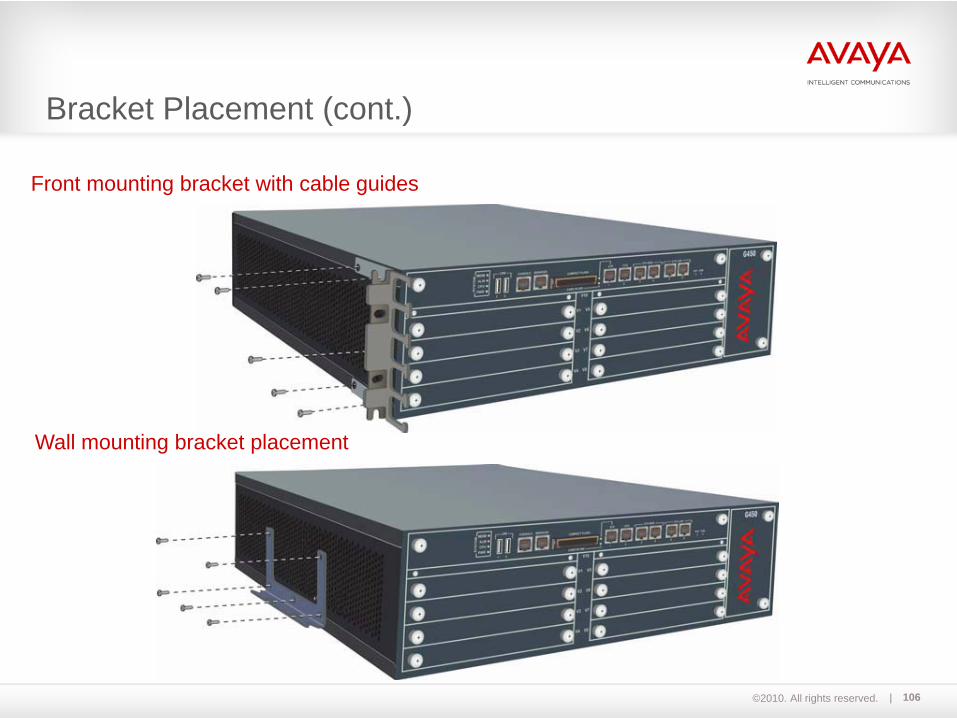
Front mounting bracket placement
Middle mounting bracket placement
Bracket Placement
©2010. All rights reserved. 106
Front mounting bracket with cable guides
Wall mounting bracket placement
Bracket Placement (cont.)
©2010. All rights reserved. 107
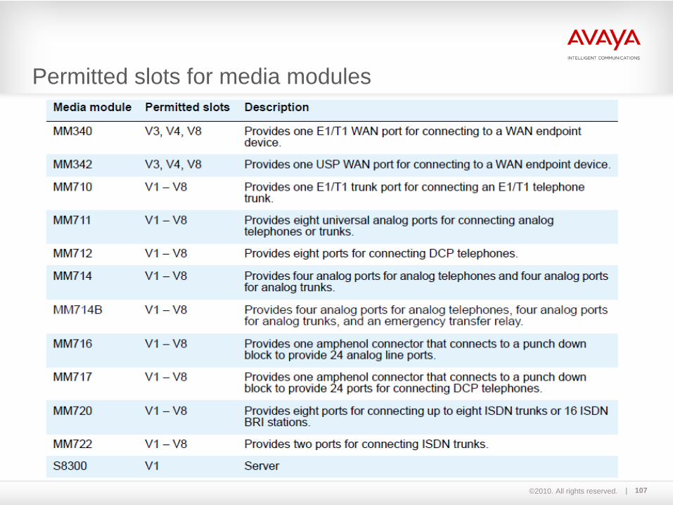
Permitted slots for media modules

©2010. All rights reserved. 108
The G450 main board has four slots as shown in the image.
Each slot can accommodate either of thetwo media processors:- An MP20 (Media Processor 20) module which
provides 25 VoIP channel resources. *- An MP80 (Media Processor 80) module which
provides 80 VoIP channel resources.Each motherboard can have a maximum of fourchildboards.
Each G450 device supports a maximum of 320 VoIP channels (with CM 5.2.1 or later).
This limitation is obtained from 8 media module slots containing an MM710 T1/E1 Media Module provisioned each as an E1 with 30DS0 channels.
DSPSlot 1
DSPSlot 4
DSPSlot 2
DSPSlot 3
Memory SIMMs
* The MP20 module is End of Sale
Media Resources on G450 main board

©2010. All rights reserved. 109
G450 Main Board
G450 main board (Replacing a G450 main board does not require a new license file)
G450 MG Power Supply Unit
A G450 MG power supply unit provides fully redundant and load -sharing power supply units, 1+1.
G450 MG Fans
G450 MG fan offers one-minute replacement window after the fan unit is pulled out.
Field Replaceable Units (FRUs) for G450

©2010. All rights reserved. 110
1...250 MG001 v4 05
gate
way
mod
ule
circ
uit
001v4
G450 Port Addressing
©2010. All rights reserved. 111
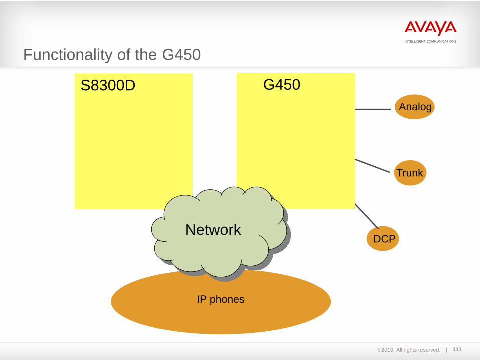
Functionality of the G450
IP phones
DCP
Analog
Trunk
S8300D G450
Network
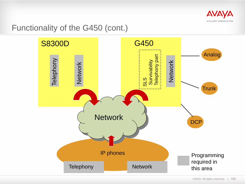
©2010. All rights reserved. 112
IP phones
DCP
Analog
Trunk
S8300D G450
Network
Tele
phon
y
NetworkTelephony
Programmingrequired inthis area
SLS
(Sur
viva
bilit
y‚T
elep
hony
part‘
Functionality of the G450 (cont.)
Net
wor
k
Net
wor
k
©2010. All rights reserved. 113
Communication between S8300D and G450Lecture

©2010. All rights reserved. 114
Contains:MGP PMI VoIPSwitching
MGP: - Media Gateway Processor- Control of media module slots- Control of internal VoIP resource- Communication with server (Media Gateway Controller)via H.248
PMI: - Primary Management Interface- "IP address of gateway"
V2
V1 S8300D
G450 Main Board
V5
V6
V7
ETHWAN
ETHLAN
ETHLAN
V7 CPU
InternalSwitch
V3
V4 V8
ETR CCA ETHWAN
Console
Services
Fan
unit
MGP and PMI
©2010. All rights reserved. 115
VoIP: - Integrated media resource for voice compression- Codec G.711, G.729, G.723- Max. 32 VoIP channels when using G.711 only- Max. 16 VoIP channels when using G.729, G.723 only
Switching: - Integrated layer 2 and 3 switching- ETH LAN and ETH WAN sockets
Contains:MGP PMI VoIPSwitching
V2
V1 S8300D
G450 Main Board
V5
V6
V7
ETHWAN
ETHLAN
ETHLAN
V7 CPU
InternalSwitch
V3
V4 V8
ETR CCA ETHWAN
Console
Services
Fan
unit
VoIP and Router
©2010. All rights reserved. 116
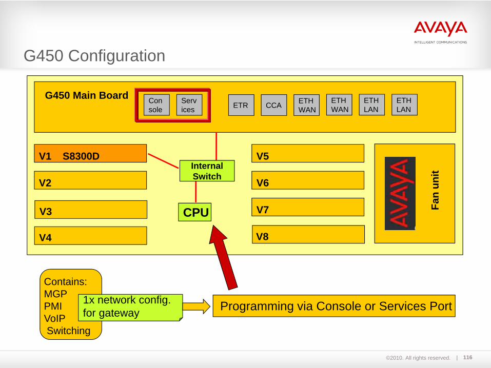
Programming via Console or Services Port
Contains:MGP PMI VoIPSwitching
1x network config.for gateway
V2
V1 S8300D
G450 Main Board
V5
V6
V7
ETHWAN
ETHLAN
ETHLAN
V7 CPU
InternalSwitch
V3
V4 V8
ETR CCA ETHWAN
Console
Services
Fan
unit
G450 Configuration

©2010. All rights reserved. 117
- S8300D plug-in server requires separate network configuration(IP address, subnet mask)
program using server's System Management Interface (SMI)
- Here, S8300D plug-in server functions as media gateway controller (MGC)(MGC could also be a remote server in the network, e.g. S8800)
V2
V1 S8300D
G450 Main Board
V5
V6
V7
ETHWAN
ETHLAN
ETHLAN
V7 CPU
InternalSwitch
V3
V4 V8
ETR CCA ETHWAN
Console
Services
Fan
unit
1x network config.for server via ServicesPort of S8300D
S8300D Configuration
©2010. All rights reserved. 118
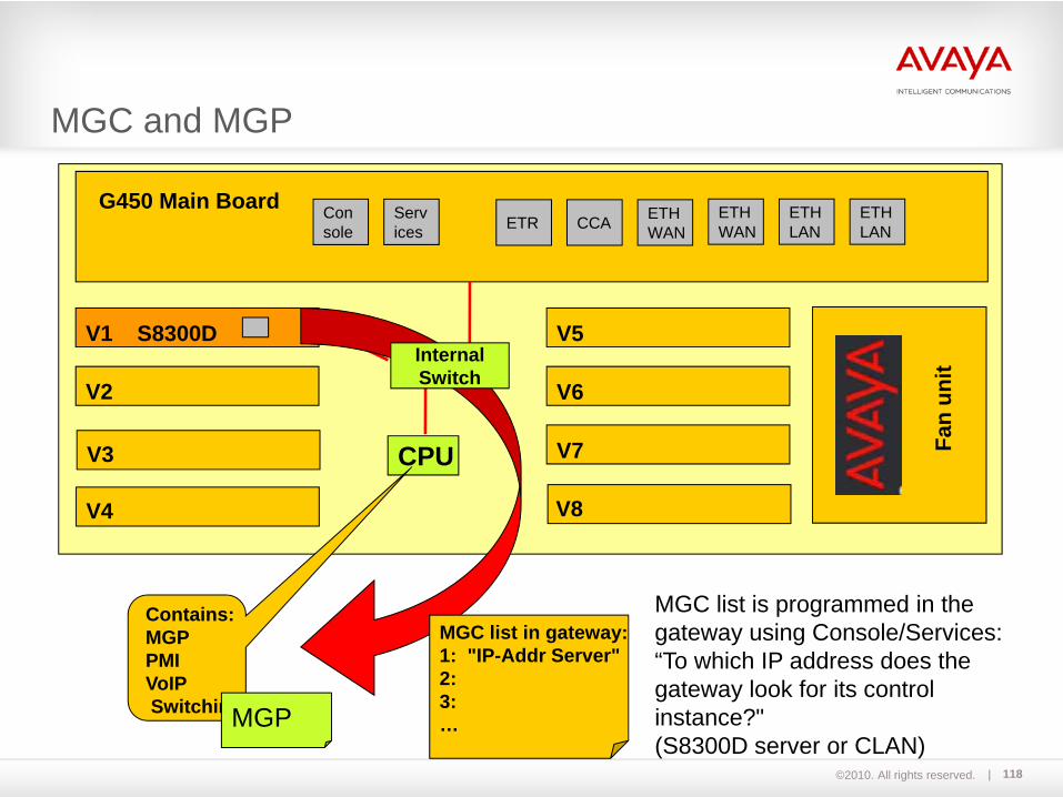
MGC list is programmed in the gateway using Console/Services:“To which IP address does thegateway look for its control instance?"(S8300D server or CLAN)
V2
V1 S8300D
G450 Main Board
V5
V6
V7
ETHWAN
ETHLAN
ETHLAN
V7 CPUV3
V4 V8
ETR CCA ETHWAN
Console
Services
Fan
unit
Contains:MGP PMI VoIPSwitchingMGP
MGC list in gateway:1: "IP-Addr Server"2:3:…
InternalSwitch
MGC and MGP
©2010. All rights reserved. 119
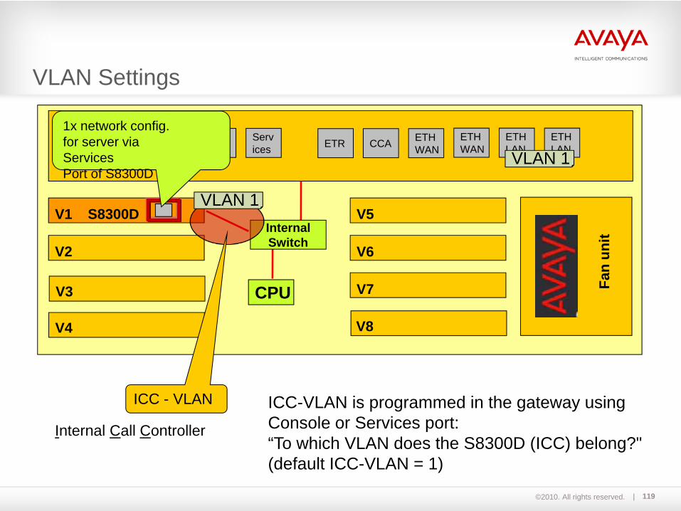
ICC-VLAN ICC-VLAN is programmed in the gateway using Console or Services port:“To which VLAN does the S8300D (ICC) belong?"(default ICC-VLAN = 1)
V2
V1 S8300D
G450 Main Board
V5
V6
V7
ETHWAN
ETHLAN
ETHLAN
V7 CPU
InternalSwitch
V3
V4 V8
ETR CCA ETHWAN
Console
Services
Fan
unit
1x network config.for server via ServicesPort of S8300D
VLAN 1
VLAN 1
ICC - VLAN
VLAN Settings
Internal Call Controller
©2010. All rights reserved. 120
Module 07Accessing the Virtual LabLecture / Exercise

©2010. All rights reserved. 121
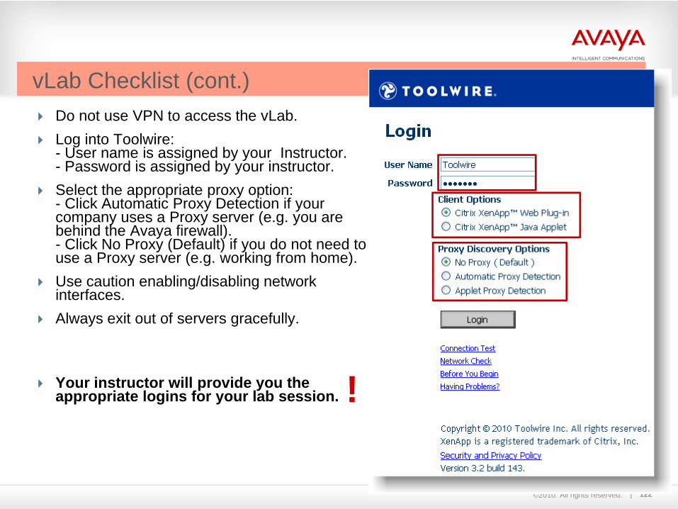
Go to https://dcm.toolwire.com/login_pro/login_pro.jsp?RID=avaya to access the Web portal for the vLab.
Ensure that you have performed the Connection Test.
Ensure that you have performed the Network Check.
Note:The information on all slides with the title red colored are for Toolwire environment only!
vLab Checklist
©2010. All rights reserved. 122
Do not use VPN to access the vLab.Log into Toolwire:- User name is assigned by your Instructor.- Password is assigned by your instructor. Select the appropriate proxy option:- Click Automatic Proxy Detection if your company uses a Proxy server (e.g. you are behind the Avaya firewall).- Click No Proxy (Default) if you do not need to use a Proxy server (e.g. working from home).Use caution enabling/disabling network interfaces.Always exit out of servers gracefully.
Your instructor will provide you the appropriate logins for your lab session.
vLab Checklist (cont.)
!
©2010. All rights reserved. 123
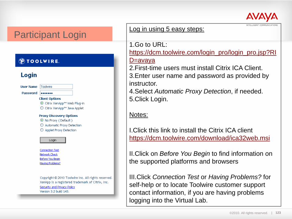
Log in using 5 easy steps:
1.Go to URL: https://dcm.toolwire.com/login_pro/login_pro.jsp?RID=avaya2.First-time users must install Citrix ICA Client.3.Enter user name and password as provided by instructor.4.Select Automatic Proxy Detection, if needed.5.Click Login.
Notes:
I.Click this link to install the Citrix ICA client https://dcm.toolwire.com/download/ica32web.msi
II.Click on Before You Begin to find information on the supported platforms and browsers
III.Click Connection Test or Having Problems? for self-help or to locate Toolwire customer support contact information, if you are having problems logging into the Virtual Lab.
Participant Login
©2010. All rights reserved. 124
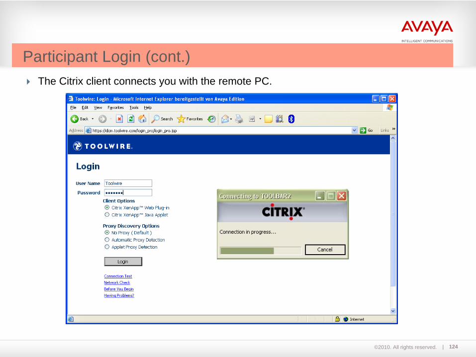
The Citrix client connects you with the remote PC.
Participant Login (cont.)

©2010. All rights reserved. 125
The system should automatically log you on to Windows. If it does not, enter administrator for User name and admin for Password.
Participant Login (cont.)
©2010. All rights reserved. 126
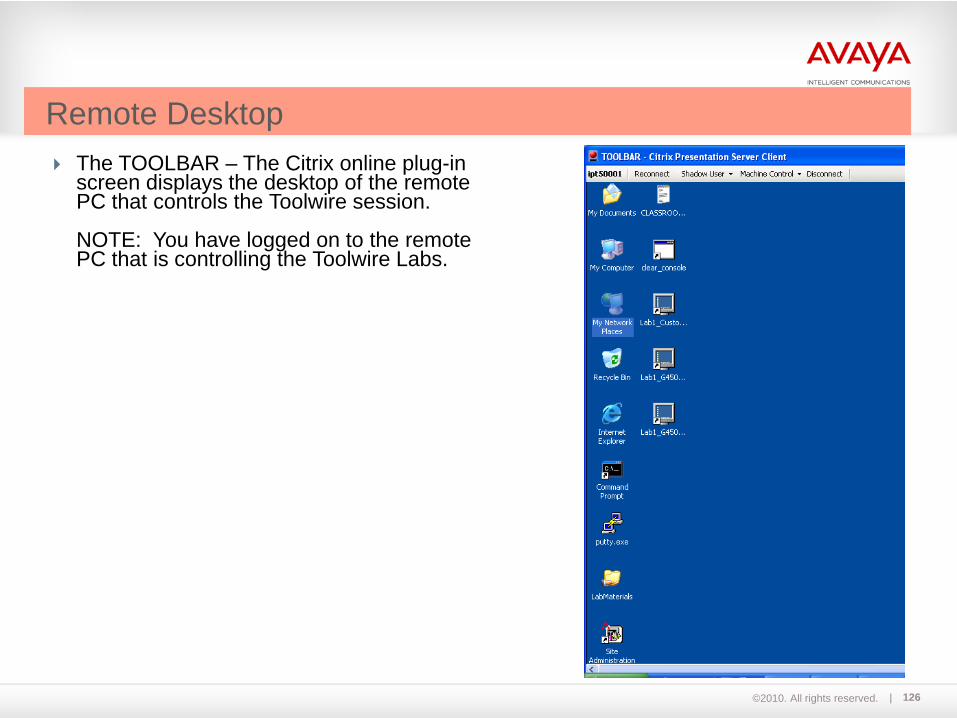
The TOOLBAR – The Citrix online plug-in screen displays the desktop of the remote PC that controls the Toolwire session.
NOTE: You have logged on to the remote PC that is controlling the Toolwire Labs.
Remote Desktop

©2010. All rights reserved. 127
Notice that each desktop icon has been labeled appropriately to help identify the lab environment. The screen on the left shows the desktop icons of the remote PCs in Lab 1 as an example.
Lab 1, G450 Gateway with S8300D
Lab 1, G450 Gateway with S8800
Remote Desktop (cont.)
©2010. All rights reserved. 128
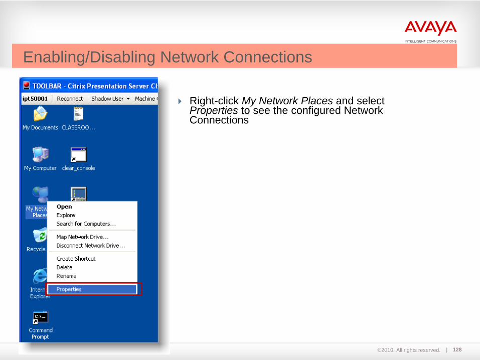
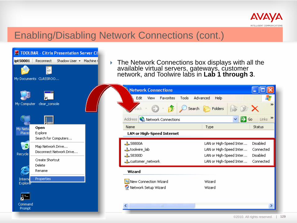
Right-click My Network Places and selectProperties to see the configured Network Connections
Enabling/Disabling Network Connections
©2010. All rights reserved. 129
The Network Connections box displays with all the available virtual servers, gateways, customer network, and Toolwire labs in Lab 1 through 3.
Enabling/Disabling Network Connections (cont.)
©2010. All rights reserved. 130
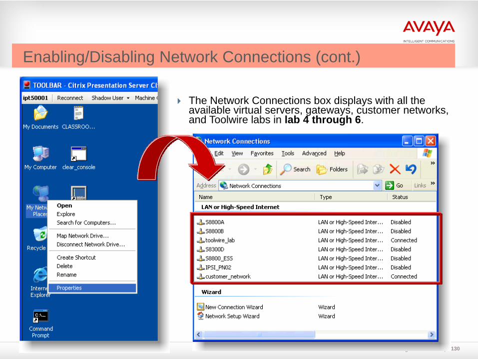
The Network Connections box displays with all the available virtual servers, gateways, customer networks, and Toolwire labs in lab 4 through 6.
Enabling/Disabling Network Connections (cont.)

©2010. All rights reserved. 131
Right-click on the network connection you would like to configure and select Enable.Notes:
- Enable only one network connection of a server or gateway at time.- Do not disable the “toolwire_lab” network connection.
Enabling/Disabling Network Connections (cont.)
©2010. All rights reserved. 132
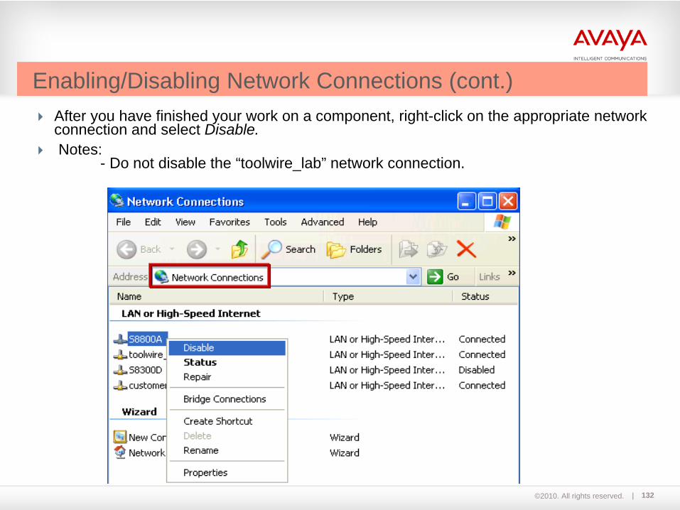
After you have finished your work on a component, right-click on the appropriate network connection and select Disable.Notes:
- Do not disable the “toolwire_lab” network connection.
Enabling/Disabling Network Connections (cont.)

©2010. All rights reserved. 133
An instructor or student can shadow another account on Toolwire.Simply click on the Shadow User drop-down menu and select the username of the person you wish to shadow.When done, press Control+Tab to stop shadowing.
Shadow screen ofuser ipt50001
Instructor or Participant Shadowing
Shadowing

©2010. All rights reserved. 134
The vLab PC uses an English-based keyboard emulation. You have the option of displaying an On-Screen Keyboard if you are not familiar with the English-based keyboard.
On-screen Keyboard

©2010. All rights reserved. 135
Double-click the clear_console icon to clear a specific console port in the lab environment (in case of malfunction).
Clear Console connections

©2010. All rights reserved. 136
Lab Exercises Accessing the Virtual LabLab 1 to 6:
Perform a Toolwire connection test (slide 121).
Perform a Toolwire network check (slide 121).
Log in to Toolwire and familiarize yourself with the remote PC(slides 122-135).
136
NoteThe instructor will provide the necessary login credentials.

©2010. All rights reserved. 137
End of Day 1


