Embed Size (px)
DESCRIPTION
at commands
Citation preview
MC52iMC52i Terminal
Version: 01.201DocId: MC52i_ATC_V01.201
AT
Com
man
d S
et
MC52i AT Command Set
MC52i_ATC_V01.201 Page 2 of 551 4/16/10Confidential / Released
GENERAL NOTE THE USE OF THE PRODUCT INCLUDING THE SOFTWARE AND DOCUMENTATION (THE "PRODUCT") ISSUBJECT TO THE RELEASE NOTE PROVIDED TOGETHER WITH PRODUCT. IN ANY EVENT THE PROVI-SIONS OF THE RELEASE NOTE SHALL PREVAIL. THIS DOCUMENT CONTAINS INFORMATION ON CIN-TERION PRODUCTS. THE SPECIFICATIONS IN THIS DOCUMENT ARE SUBJECT TO CHANGE ATCINTERION'S DISCRETION. CINTERION WIRELESS MODULES GMBH GRANTS A NON-EXCLUSIVERIGHT TO USE THE PRODUCT. THE RECIPIENT SHALL NOT TRANSFER, COPY, MODIFY, TRANSLATE,REVERSE ENGINEER, CREATE DERIVATIVE WORKS; DISASSEMBLE OR DECOMPILE THE PRODUCTOR OTHERWISE USE THE PRODUCT EXCEPT AS SPECIFICALLY AUTHORIZED. THE PRODUCT ANDTHIS DOCUMENT ARE PROVIDED ON AN "AS IS" BASIS ONLY AND MAY CONTAIN DEFICIENCIES ORINADEQUACIES. TO THE MAXIMUM EXTENT PERMITTED BY APPLICABLE LAW, CINTERION WIRELESSMODULES GMBH DISCLAIMS ALL WARRANTIES AND LIABILITIES. THE RECIPIENT UNDERTAKES FORAN UNLIMITED PERIOD OF TIME TO OBSERVE SECRECY REGARDING ANY INFORMATION AND DATAPROVIDED TO HIM IN THE CONTEXT OF THE DELIVERY OF THE PRODUCT. THIS GENERAL NOTESHALL BE GOVERNED AND CONSTRUED ACCORDING TO GERMAN LAW.
CopyrightTransmittal, reproduction, dissemination and/or editing of this document as well as utilization of its contents andcommunication thereof to others without express authorization are prohibited. Offenders will be held liable forpayment of damages. All rights created by patent grant or registration of a utility model or design patent arereserved.
Copyright © 2010, Cinterion Wireless Modules GmbH
Trademark NoticeMicrosoft and Windows are either registered trademarks or trademarks of Microsoft Corporation in the UnitedStates and/or other countries. All other registered trademarks or trademarks mentioned in this document areproperty of their respective owners.
Document Name: MC52i AT Command Set
Version: 01.201
Date: April 16, 2010
DocId: MC52i_ATC_V01.201
Status Confidential / Released
MC52i AT Command Set Contents
MC52i_ATC_V01.201 Page 3 of 551 4/16/10Confidential / Released
1. Introduction............................................................................................................................................ 14
1.1 Scope of the document ................................................................................................................. 14
1.2 Related documents ....................................................................................................................... 15
1.3 Document Conventions ................................................................................................................. 16
1.3.1 Quick reference table..................................................................................................... 16
1.3.2 Superscript notation for parameters and values ............................................................ 17
1.4 AT Command Syntax .................................................................................................................... 18
1.4.1 Using Parameters .......................................................................................................... 18
1.4.2 Concatenating AT Commands....................................................................................... 19
1.5 Communication between Customer Application and MC52i ......................................................... 20
1.6 Supported character sets .............................................................................................................. 21
1.6.1 GSM alphabet tables and UCS2 character values ........................................................ 22
1.6.2 UCS2 and GSM character coding and conversion ........................................................ 24
1.6.2.1 Output of SIM data (ME to TE) ...................................................................................... 24
1.6.2.2 Input of SIM data (TE to ME) ......................................................................................... 25
1.7 Unsolicited Result Code Presentation........................................................................................... 26
1.8 Errors and Messages .................................................................................................................... 27
1.9 Auxiliary Serial Interface................................................................................................................ 28
1.10 Serial Interface Flow Control ......................................................................................................... 29
1.10.1 Software Flow Control (XON/OFF Handshake)............................................................. 29
1.10.2 Hardware Flow Control (RTS/CTS Handshake) ............................................................ 29
1.11 Common PCN Handset Specification (CPHS) .............................................................................. 30
2. Configuration Commands..................................................................................................................... 31
2.1 AT&F Set all current parameters to manufacturer defaults ......................................................... 31
2.2 AT&V Display current configuration ............................................................................................ 32
2.2.1 AT&V responses............................................................................................................ 33
2.3 AT&W Stores current configuration to user defined profile ......................................................... 34
2.4 ATQ Result code presentation mode .......................................................................................... 35
2.5 ATV Result code format mode .................................................................................................... 36
2.5.1 Verbose and numeric result codes ................................................................................ 36
2.6 ATX Set CONNECT result code format and call monitoring ....................................................... 37
2.7 ATZ Set all current parameters to user defined profile................................................................ 38
2.8 AT+CFUN Functionality Level ..................................................................................................... 39
2.8.1 Wake up the ME from SLEEP mode ............................................................................. 43
2.9 AT^SMSO Switch Off MC52i....................................................................................................... 44
2.10 AT+GCAP Request complete TA capabilities list........................................................................ 45
2.11 AT+CMEE Mobile Equipment Error Message Format ................................................................ 46
2.11.1 CME/CMS Error Code Overview ................................................................................... 47
2.12 AT+CSCS Select TE character set ............................................................................................. 51
2.13 AT^SCFG Extended Configuration Settings ............................................................................... 52
2.14 AT^SM20 Set M20 compatibility mode ....................................................................................... 62
3. Status Control Commands ................................................................................................................... 63
3.1 AT+CMER Mobile Equipment Event Reporting .......................................................................... 63
3.2 AT+CIND Indicator control .......................................................................................................... 65
Contents
MC52i AT Command Set Contents
MC52i_ATC_V01.201 Page 4 of 551 4/16/10Confidential / Released
3.3 AT^SIND Extended Indicator Control .......................................................................................... 68
3.4 AT+CEER Extended Error Report............................................................................................... 74
3.4.1 Cause Location ID for the extended error report ........................................................... 75
3.4.2 Proprietary L2 cause...................................................................................................... 76
3.4.3 GSM release cause for L3 Radio Resource (RR).......................................................... 76
3.4.4 Proprietary release cause for L3 Radio Resource (RR) ................................................ 77
3.4.5 GSM release cause for Mobility Management (MM) or Session Management (SM)..... 77
3.4.6 Proprietary release cause for L3 Mobility Management (MM) ....................................... 78
3.4.7 GSM release cause for L3 Call Control (CC)................................................................. 79
3.4.8 Proprietary release cause for L3 Call Control (CC) ....................................................... 80
3.4.9 Proprietary release cause for L3 Advice of Charge (AOC)............................................ 81
3.4.10 GSM Release cause for Supplementary Service Call ................................................... 81
3.4.11 Proprietary release cause for Call-related Supplementary Services (CRSS)................ 82
3.4.12 Proprietary release cause for Session Management (SM) ............................................ 83
3.4.13 GSM cause for L3 Protocol module or other local cause ............................................. 83
3.4.14 Proprietary release cause for GPRS API....................................................................... 84
3.4.15 Proprietary release cause for PPP/IP-Stack.................................................................. 84
3.5 ATS18 Extended call release report............................................................................................ 85
3.6 AT+CPAS Mobile equipment activity status................................................................................ 87
3.7 AT+WS46 Select wireless network ............................................................................................. 88
4. Serial Interface Control Commands..................................................................................................... 89
4.1 AT\Q Flow control........................................................................................................................ 89
4.2 AT&C Set Data Carrier Detect (DCD) Line mode ....................................................................... 90
4.3 AT&D Set Data Terminal Ready (DTR) line mode ...................................................................... 91
4.4 AT&S Set Data Set Ready (DSR) line mode............................................................................... 92
4.5 ATE Enable command echo........................................................................................................ 93
4.6 AT+ILRR Set TE-TA local rate reporting..................................................................................... 94
4.7 AT+IPR Bit Rate.......................................................................................................................... 96
4.7.1 Autobauding................................................................................................................... 97
4.8 AT+CMUX Multiplex Mode.......................................................................................................... 99
4.8.1 Restrictions on Multiplex mode.................................................................................... 100
5. Security Commands............................................................................................................................ 102
5.1 AT+CPIN PIN Authentication .................................................................................................... 102
5.1.1 What to do if PIN or password authentication fails? .................................................... 104
5.2 AT+CPIN2 PIN2 Authentication ................................................................................................ 106
5.3 AT^SPIC Display PIN counter ................................................................................................... 108
5.4 AT+CLCK Facility lock .............................................................................................................. 112
5.5 AT^SLCK Facility lock ............................................................................................................... 117
5.6 AT+CPWD Change Password .................................................................................................. 118
5.7 AT^SPWD Change Password................................................................................................... 122
6. Identification Commands.................................................................................................................... 123
6.1 ATI Display product identification information ........................................................................... 123
6.2 AT+CGMI Request manufacturer identification......................................................................... 124
6.3 AT+GMI Request manufacturer identification ........................................................................... 124
6.4 AT+CGMM Request model identification .................................................................................. 125
6.5 AT+GMM Request model identification..................................................................................... 125
6.6 AT+CGMR Request revision identification of software status................................................... 126
MC52i AT Command Set Contents
MC52i_ATC_V01.201 Page 5 of 551 4/16/10Confidential / Released
6.7 AT+GMR Request revision identification of software status ..................................................... 126
6.8 AT+CGSN Request International Mobile Equipment Identity (IMEI) ......................................... 127
6.9 AT+GSN Request International Mobile Equipment Identity (IMEI) ........................................... 127
6.10 AT+CIMI Request International Mobile Subscriber Identity (IMSI)............................................ 128
7. Call related Commands....................................................................................................................... 129
7.1 Call Status Information ................................................................................................................ 129
7.2 ATA Answer a call ..................................................................................................................... 130
7.3 ATD Mobile originated call to specified number ........................................................................ 131
7.4 ATD><mem><n> Mobile originated call using specific memory and index number ................. 133
7.5 ATD><n> Mobile originated call from active memory using index number ............................... 135
7.6 ATD><str> Mobile originated call from active memory using corresponding field .................... 136
7.7 ATDI Mobile originated call to ISDN number............................................................................. 137
7.8 ATDL Redial last number used ................................................................................................. 138
7.9 ATH Disconnect existing connection......................................................................................... 139
7.10 AT+CHUP Hang up call ............................................................................................................ 140
7.11 AT^SHUP Hang up call(s) indicating a specific GSM04.08 release cause ............................... 141
7.12 ATS0 Set number of rings before automatically answering a call ............................................. 142
7.13 ATS6 Set pause before blind dialing ......................................................................................... 143
7.14 ATS7 Set number of seconds to wait for connection completion .............................................. 144
7.15 ATS8 Set number of seconds to wait for comma dialing modifier............................................. 145
7.16 ATS10 Set disconnect delay after indicating the absence of data carrier ................................. 146
7.17 ATO Switch from command mode to data mode / PPP online mode........................................ 147
7.18 +++ Switch from data mode to command mode ....................................................................... 148
7.19 AT+CBST Select bearer service type ....................................................................................... 149
7.20 AT+CRLP Select radio link protocol parameters for originated non-transparent data calls ...... 150
7.21 AT+CLCC List of current calls ................................................................................................... 151
7.22 AT^SLCC Extended list of current calls .................................................................................... 153
7.23 AT+CR Service reporting control .............................................................................................. 158
7.24 AT+CRC Set Cellular Result Codes for incoming call indication .............................................. 159
7.25 AT+CSNS Single Numbering Scheme...................................................................................... 160
7.26 AT^SCNI List Call Number Information..................................................................................... 161
7.27 AT^SLCD Display Last Call Duration ........................................................................................ 162
7.28 AT^STCD Display Total Call Duration....................................................................................... 163
7.29 ATP Select pulse dialing ........................................................................................................... 164
7.30 ATT Select tone dialing ............................................................................................................. 164
7.31 ATS2 Set escape sequence character...................................................................................... 165
8. Network Service Commands .............................................................................................................. 166
8.1 AT+COPN Read operator names ............................................................................................. 166
8.2 AT+COPS Operator Selection .................................................................................................. 167
8.3 AT^SOPS Extended Operator Selection................................................................................... 170
8.4 AT+CREG Network registration ................................................................................................ 172
8.5 AT+CSQ Signal quality ............................................................................................................. 175
8.6 AT^SMONC Cell Monitoring...................................................................................................... 176
8.7 AT^SMOND Cell Monitoring...................................................................................................... 178
8.8 AT^MONI Monitor idle mode and dedicated mode ................................................................... 181
8.8.1 AT^MONI responses.................................................................................................... 182
8.8.2 Service states .............................................................................................................. 183
8.9 AT^MONP Monitor neighbor cells ............................................................................................. 184
MC52i AT Command Set Contents
MC52i_ATC_V01.201 Page 6 of 551 4/16/10Confidential / Released
8.9.1 AT^MONP responses .................................................................................................. 185
8.10 AT^SMONG Packet Data Monitor ............................................................................................. 186
8.10.1 AT^SMONG Cell Info Table......................................................................................... 187
8.11 AT^SALS Alternate Line Service............................................................................................... 188
8.12 AT^SHOM Display Homezone .................................................................................................. 190
8.13 AT^SPLM Read the PLMN list .................................................................................................. 191
8.14 AT+CPOL Preferred Operator List ............................................................................................ 192
8.15 AT^SPLR Read entry from the preferred operators list............................................................. 193
8.16 AT^SPLW Write an entry to the preferred operators list ........................................................... 194
9. Supplementary Service Commands .................................................................................................. 195
9.1 AT+CACM Accumulated call meter (ACM) reset or query ........................................................ 195
9.2 AT^SACM Advice of charge and query of ACM and ACMmax ................................................. 196
9.3 AT+CAMM Accumulated call meter maximum (ACMmax) set or query.................................... 198
9.4 AT+CAOC Advice of Charge information.................................................................................. 199
9.5 AT+CCUG Closed User Group ................................................................................................. 200
9.6 AT+CCFC Call forwarding number and conditions control ....................................................... 202
9.7 AT+CCWA Call Waiting ............................................................................................................ 206
9.8 AT+CHLD Call Hold and Multiparty........................................................................................... 210
9.9 AT+CLIP Calling Line Identification Presentation ..................................................................... 212
9.10 AT+CLIR Calling Line Identification Restriction ........................................................................ 214
9.11 AT+COLP Connected Line Identification Presentation ............................................................. 215
9.12 AT+CPUC Price per unit and currency table............................................................................. 217
9.13 AT+CSSN Supplementary service notifications ........................................................................ 219
9.14 AT+CUSD Unstructured supplementary service data............................................................... 221
10. Internet Service Commands ............................................................................................................... 223
10.1 AT^SICS Internet Connection Setup Profile.............................................................................. 226
10.1.1 Example: Default values of a CSD connection profile ................................................. 228
10.1.2 Example: GPRS connection profile ............................................................................. 229
10.2 AT^SICI Internet Connection Information.................................................................................. 230
10.2.1 Checking Connection Profile Status ............................................................................ 231
10.3 AT^SISS Internet Service Setup Profile .................................................................................... 233
10.4 AT^SISI Internet Service Information ........................................................................................ 243
10.5 AT^SISO Internet Service Open ............................................................................................... 245
10.5.1 Example: Accepting / Rejecting Socket Connection Request from Remote Client ..... 249
10.6 AT^SISC Internet Service Close ............................................................................................... 251
10.7 AT^SISR Internet Service Read Data ....................................................................................... 252
10.7.1 Example: Socket Host Reads Small Amounts of UDP Data Packets (URC Mode)..... 253
10.8 AT^SISW Internet Service Write Data....................................................................................... 255
10.8.1 Usage of parameter <eodFlag>................................................................................... 257
10.9 AT^SIST Enter Transparent Access Mode ............................................................................... 258
10.10 AT^SISE Internet Service Error Report ..................................................................................... 260
10.11 Internet Service URC "^SIS" ....................................................................................................... 261
10.11.1 Information Elements Related to the Service Application............................................ 262
10.11.2 Information Elements Related to FTP Service............................................................. 263
10.11.3 Information Elements Related to HTTP Service .......................................................... 264
10.11.4 Information Elements Related to POP3 Service.......................................................... 264
10.11.5 Information Elements Related to SMTP Service ......................................................... 264
10.12 Examples of how to Configure and Use Internet Service Profiles............................................... 265
MC52i AT Command Set Contents
MC52i_ATC_V01.201 Page 7 of 551 4/16/10Confidential / Released
10.12.1 Selecting URC Mode or Polling Mode ......................................................................... 265
10.12.2 Configuring Socket Listener......................................................................................... 265
10.12.3 Configuring Socket Client for Calling a Socket Listener on Another Host ................... 266
10.12.4 Socket Client Sends Data via TCP Connection (Polling Mode)................................... 266
10.12.5 Socket client sends data via TCP connection with URCs............................................ 267
10.12.6 Configuring and Using FTP Download (URC Mode) ................................................... 267
10.12.7 Configuring and Using FTP Upload (URC Mode)........................................................ 268
10.12.8 Configuring SMPT Service Profile ............................................................................... 268
10.12.9 Sending Email (URC Mode) ........................................................................................ 269
10.12.10 Sending Email (Polling Mode) ..................................................................................... 270
10.12.11 Configuring POP3 Service Profile................................................................................ 271
10.12.12 Retrieving Email (URC Mode) ..................................................................................... 272
10.12.13 Retrieving Email (Polling Mode) .................................................................................. 272
10.12.14 HTTP POST (Polling Mode) ........................................................................................ 273
10.12.15 HTTP GET (Polling Mode)........................................................................................... 274
10.12.16 Creating Transparent TCP Socket Client .................................................................... 275
10.12.17 Opening and Closing Transparent TCP Service.......................................................... 275
10.12.18 Server Disconnects While Transparent TCP Service is in Transparent Access Mode 275
10.12.19 Server Disconnects While Transparent TCP Service is in AT Command Mode ......... 276
10.12.20 Server Disconnects While Transparent TCP Service is in AT Command Mode and Data is Pending .................................................................................................................... 276
11. GPRS Commands................................................................................................................................ 277
11.1 AT+CGACT PDP context activate or deactivate ....................................................................... 277
11.2 AT+CGANS Manual response to a network request for PDP context activation ...................... 279
11.3 AT+CGATT GPRS attach or detach ......................................................................................... 281
11.4 AT+CGAUTO Automatic response to a network request for PDP context activation ............... 282
11.5 AT+CGEREP GPRS event reporting ........................................................................................ 284
11.6 AT+CGDATA Enter data state .................................................................................................. 286
11.6.1 Automatic deactivation of PDP context during dial-up PPP......................................... 287
11.7 AT+CGDCONT Define PDP Context ........................................................................................ 288
11.8 AT+CGPADDR Show PDP address ......................................................................................... 290
11.9 AT+CGQMIN Quality of Service Profile (Minimum acceptable) ................................................ 291
11.10 AT+CGQREQ Quality of Service Profile (Requested) .............................................................. 295
11.11 AT+CGREG GPRS Network Registration Status...................................................................... 299
11.12 AT+CGSMS Select service for MO SMS messages................................................................. 301
11.13 AT^SGAUTH Set type of authentication for PPP connection.................................................... 302
11.14 AT^SGCONF Configuration of GPRS related Parameters ...................................................... 303
11.15 ATA Manual response to a network request for PDP context activation................................... 304
11.16 ATD*99# Request GPRS service.............................................................................................. 305
11.17 ATD*98# Request GPRS IP service ......................................................................................... 306
11.18 ATH Manual rejection of a network request for PDP context activation.................................... 307
11.19 ATS0 Automatic response to a network request for PDP context activation............................. 308
11.20 Using GPRS AT commands (Examples)..................................................................................... 309
11.21 Using the GPRS dial command ATD .......................................................................................... 311
12. FAX Commands................................................................................................................................... 312
12.1 FAX parameters .......................................................................................................................... 312
12.1.1 Summary of Fax Class 2 URCs defined by EIA PN-2388 ........................................... 314
12.2 AT+FBADLIN Bad Line Threshold ............................................................................................ 315

MC52i AT Command Set Contents
MC52i_ATC_V01.201 Page 8 of 551 4/16/10Confidential / Released
12.3 AT+FBADMUL Error Threshold Multiplier ................................................................................. 316
12.4 AT+FBOR Query data Bit Order ............................................................................................... 317
12.5 AT+FCIG Query or set the Local Polling ID .............................................................................. 318
12.6 AT+FCLASS Fax: Select, read or test service class................................................................. 319
12.7 AT+FCQ Copy Quality Checking .............................................................................................. 320
12.8 AT+FCR Capability to Receive ................................................................................................. 321
12.9 AT+FDCC Query or set capabilities .......................................................................................... 322
12.10 AT+FDFFC Data Compression Format Conversion ................................................................. 323
12.11 AT+FDIS Query or set session parameters .............................................................................. 324
12.12 AT+FDR Begin or continue phase C Data Reception ............................................................... 325
12.13 AT+FDT Data Transmission...................................................................................................... 326
12.14 AT+FET End a page or document ............................................................................................ 327
12.15 AT+FK Kill operation, orderly FAX abort ................................................................................... 328
12.16 AT+FLID Query or set the Local Id setting capabilities ............................................................. 329
12.17 AT+FMDL Identify Product Model ............................................................................................ 330
12.18 AT+FMFR Request Manufacturer Identification........................................................................ 331
12.19 AT+FOPT Set bit Order independently ..................................................................................... 332
12.20 AT+FPHCTO DTE Phase C Response Timeout....................................................................... 333
12.21 AT+FREV Identify Product Revision ......................................................................................... 334
12.22 AT+FRH Receive Data Using HDLC Framing .......................................................................... 335
12.23 AT+FRM Receive Data ............................................................................................................. 336
12.24 AT+FRS Receive Silence.......................................................................................................... 337
12.25 AT+FTH Transmit Data Using HDLC Framing.......................................................................... 338
12.26 AT+FTM Transmit Data............................................................................................................. 339
12.27 AT+FTS Stop Transmission and Wait ....................................................................................... 340
12.28 AT+FVRFC Vertical Resolution Format Conversion ................................................................. 341
13. Short Message Service (SMS) Commands........................................................................................ 342
13.1 SMS parameters ......................................................................................................................... 342
13.2 AT+CMGC Send an SMS command......................................................................................... 346
13.3 AT+CMGD Delete short message............................................................................................. 347
13.4 AT+CMGF Select SMS message format .................................................................................. 348
13.5 AT+CMGL List SMS messages from preferred store................................................................ 349
13.6 AT+CMGR Read SMS messages............................................................................................. 351
13.7 AT+CMGS Send Short Message .............................................................................................. 353
13.8 AT+CMGW Write Short Messages to Memory ......................................................................... 355
13.9 AT+CMSS Send short messages from storage ........................................................................ 357
13.10 AT+CNMA New Message Acknowledgement to ME/TE, only phase 2+ .................................. 358
13.11 AT+CNMI New short Message Indication ................................................................................. 359
13.12 AT+CPMS Preferred SMS message storage............................................................................ 362
13.13 AT+CSCA SMS Service Center Address.................................................................................. 364
13.14 AT+CSCB Select Cell Broadcast Message Indication .............................................................. 365
13.15 AT+CSDH Show SMS text mode parameters........................................................................... 366
13.16 AT+CSMP Set SMS text Mode Parameters.............................................................................. 367
13.17 AT+CSMS Select Message Service.......................................................................................... 369
13.18 AT^SLMS List SMS Memory Storage ....................................................................................... 371
13.19 AT^SMGL List Short Messages from preferred store without setting status to REC READ ..... 372
13.20 AT^SMGO Set or query SMS overflow presentation mode or query SMS overflow ................. 373
13.21 AT^SMGR Read short message without setting status to REC READ..................................... 375

MC52i AT Command Set Contents
MC52i_ATC_V01.201 Page 9 of 551 4/16/10Confidential / Released
13.22 AT^SSCONF SMS Command Configuration ........................................................................... 376
13.23 AT^SSDA Set SMS Display Availability .................................................................................... 377
13.24 AT^SSMSS Set Short Message Storage Sequence ................................................................. 378
14. SIM related Commands....................................................................................................................... 379
14.1 AT+CRSM Restricted SIM Access............................................................................................ 379
14.2 AT^SXSM Extended SIM Access.............................................................................................. 381
14.3 AT^SCKS Query SIM and Chip Card Holder Status ................................................................. 383
14.4 AT^SCID Display SIM card identification number ..................................................................... 385
14.5 AT+CXXCID Display card ID..................................................................................................... 386
15. SIM Application Toolkit (SAT) Commands........................................................................................ 387
15.1 Usage of Remote-SAT ................................................................................................................ 389
15.1.1 Automatic Response Mode (AR Mode) ....................................................................... 389
15.1.2 Explicit Response Mode (ER Mode)............................................................................ 389
15.1.3 Character Sets............................................................................................................. 389
15.1.4 SIM Update Initiated by the Network ........................................................................... 389
15.1.5 Icon Handling............................................................................................................... 389
15.1.6 Using SMS Related AT Commands ............................................................................ 390
15.2 Remote-SAT States .................................................................................................................... 391
15.2.1 Remote-SAT State Transition Diagram ....................................................................... 392
15.2.2 Remote-SAT State Transition Table............................................................................ 393
15.3 Remote-SAT Command Types ................................................................................................... 395
15.4 AT^SSTA SAT Interface Activation ........................................................................................... 397
15.5 ^SSTN SAT Notification ............................................................................................................ 399
15.6 AT^SSTGI SAT Get Information ............................................................................................... 401
15.7 AT^SSTGI SAT Get Information - Refresh (1) .......................................................................... 402
15.8 AT^SSTGI SAT Get Information - Set Up Event List (5) ........................................................... 404
15.9 AT^SSTGI SAT Get Information - Set Up Call (16)................................................................... 405
15.10 AT^SSTGI SAT Get Information - Send SS (17)....................................................................... 407
15.11 AT^SSTGI SAT Get Information - Send USSD (18) ................................................................. 408
15.12 AT^SSTGI SAT Get Information - Send Short Message (19) ................................................... 409
15.13 AT^SSTGI SAT Get Information - Send DTMF (20) ................................................................. 410
15.14 AT^SSTGI SAT Get Information - Launch Browser (21) ........................................................... 411
15.15 AT^SSTGI SAT Get Information - Play Tone (32)..................................................................... 413
15.16 AT^SSTGI SAT Get Information - Display Text (33) ................................................................. 415
15.17 AT^SSTGI SAT Get Information - Get Inkey (34) ..................................................................... 417
15.18 AT^SSTGI SAT Get Information - Get Input (35) ...................................................................... 419
15.19 AT^SSTGI SAT Get Information - Select Item (36) ................................................................... 421
15.20 AT^SSTGI SAT Get Information - Set up Menu (37) ................................................................ 423
15.21 AT^SSTGI SAT Get Information - Set up Idle Mode Text (40).................................................. 425
15.22 AT^SSTR SAT Response ......................................................................................................... 426
15.23 AT^SSTR SAT Response - Refresh (1) .................................................................................... 427
15.24 AT^SSTR SAT Response - Set Up Event List (5) ..................................................................... 428
15.25 AT^SSTR SAT Response - Set Up Call (16) ............................................................................ 429
15.26 AT^SSTR SAT Response - Send SS (17) ................................................................................ 430
15.27 AT^SSTR SAT Response - Send USSD (18) ........................................................................... 431
15.28 AT^SSTR SAT Response - Send Short Message (19) ............................................................. 432
15.29 AT^SSTR SAT Response - Send DTMF (20) ........................................................................... 433
15.30 AT^SSTR SAT Response - Launch Browser (21)..................................................................... 434
MC52i AT Command Set Contents
MC52i_ATC_V01.201 Page 10 of 551 4/16/10Confidential / Released
15.31 AT^SSTR SAT Response - Play Tone (32) .............................................................................. 435
15.32 AT^SSTR SAT Response - Display Text (33) ........................................................................... 436
15.33 AT^SSTR SAT Response - Get Inkey (34) ............................................................................... 437
15.34 AT^SSTR SAT Response - Get Input (35)................................................................................ 439
15.35 AT^SSTR SAT Response - Select Item (36)............................................................................. 440
15.36 AT^SSTR SAT Response - Setup Menu (37) ........................................................................... 441
15.37 AT^SSTR SAT Response - Set Up Idle Mode Text (40) ........................................................... 442
15.38 AT^SSTR SAT Event - Menu Selection (211) ........................................................................... 443
15.39 AT^SSTR SAT Event - User Activity (232)................................................................................ 444
15.40 AT^SSTR SAT Event - Idle Screen Available (233) .................................................................. 445
15.41 AT^SSTR SAT Event - Language Selection (235) .................................................................... 446
15.42 AT^SSTR SAT Event - Browser Termination (236) .................................................................. 447
15.43 AT^SSTR SAT Event - Terminate Command (254) .................................................................. 448
15.44 Examples for Using Remote-SAT ............................................................................................... 449
16. Phonebook Commands....................................................................................................................... 452
16.1 Sort Order for Phonebooks ......................................................................................................... 452
16.2 AT+CPBR Read from Phonebook............................................................................................. 453
16.3 AT+CPBS Select phonebook memory storage ......................................................................... 456
16.4 AT+CPBW Write into Phonebook ............................................................................................. 458
16.5 AT^SPBC Find first matching entry in sorted phonebook ......................................................... 461
16.6 AT^SPBD Purge phonebook memory storage.......................................................................... 462
16.7 AT^SPBG Display phonebook entries in alphabetical order ..................................................... 463
16.8 AT^SPBS Step through the selected phonebook alphabetically ............................................... 466
16.9 AT+CNUM Read own numbers................................................................................................. 470
16.10 AT^SDLD Delete the 'last number redial' memory .................................................................... 471
17. Audio Commands................................................................................................................................ 472
17.1 Audio programming model .......................................................................................................... 472
17.2 ATL Set monitor speaker loudness ........................................................................................... 474
17.3 ATM Set monitor speaker mode................................................................................................ 474
17.4 AT+CLVL Loudspeaker volume level ........................................................................................ 475
17.5 AT+CMUT Mute control ............................................................................................................ 476
17.6 AT+VTD Tone duration ............................................................................................................. 477
17.7 AT+VTS DTMF and tone generation......................................................................................... 478
17.8 AT^SAIC Audio Interface Configuration .................................................................................... 479
17.9 AT^SNFA Set or query of microphone attenuation .................................................................. 481
17.10 AT^SNFD Set audio parameters to manufacturer default values ............................................. 483
17.11 AT^SNFI Set microphone path parameters .............................................................................. 484
17.12 AT^SNFM Set microphone audio path and power supply......................................................... 485
17.13 AT^SNFO Set audio output (= loudspeaker path) parameter ................................................... 487
17.14 AT^SNFPT Set progress tones ................................................................................................. 489
17.15 AT^SNFS Select audio hardware set ........................................................................................ 490
17.16 AT^SNFTTY Signal TTY/CTM audio mode capability............................................................... 493
17.17 AT^SNFV Set loudspeaker volume........................................................................................... 495
17.18 AT^SNFW Write audio setting in non-volatile store .................................................................. 496
17.19 AT^SRTC Ring tone configuration ............................................................................................ 497
18. Hardware related Commands............................................................................................................. 499
18.1 AT+CCLK Real Time Clock....................................................................................................... 499
MC52i AT Command Set Contents
MC52i_ATC_V01.201 Page 11 of 551 4/16/10Confidential / Released
18.2 AT+CALA Set alarm time ......................................................................................................... 500
18.3 AT^SBC Battery Charge Control ............................................................................................... 503
18.3.1 Responses returned by read command....................................................................... 505
18.4 AT^SBV Battery/Supply Voltage ............................................................................................... 506
18.5 AT^SCTM Set critical operating temperature presentation mode or query temperature........... 507
18.5.1 Deferred shutdown ...................................................................................................... 509
18.6 AT^SSYNC Configure SYNC Pin.............................................................................................. 510
18.6.1 ME status indicated by status LED patterns ................................................................ 511
19. Miscellaneous Commands.................................................................................................................. 512
19.1 A/ Repeat previous command line ............................................................................................ 512
19.2 ATS3 Set command line termination character......................................................................... 513
19.3 ATS4 Set response formatting character .................................................................................. 514
19.4 ATS5 Write command line editing character ............................................................................. 515
20. Appendix .............................................................................................................................................. 516
20.1 Restricted access to SIM data after SIM PIN authentication....................................................... 516
20.2 Star-Hash (*#) Network Commands............................................................................................ 517
20.3 Available AT Commands and Dependency on SIM PIN ............................................................. 520
20.4 Availability of AT Commands Depending on Operating Mode of ME.......................................... 528
20.5 AT Command Settings storable with AT&W................................................................................ 536
20.6 Factory Default Settings Restorable with AT&F.......................................................................... 539
20.7 Summary of Unsolicited Result Codes (URC)............................................................................. 542
20.8 Alphabetical List of AT Commands ............................................................................................. 545
MC52i AT Command Set List of Tables
MC52i_ATC_V01.201 Page 12 of 551 4/16/10Confidential / Released
Table 1.1: Product specific use of AT commands ...................................................................................... 14
Table 1.2: Symbols used to mark the type of parameters ........................................................................... 17
Table 1.3: Symbols used to indicate the correlations with other commands ............................................... 17
Table 1.4: Symbols used to mark different types of default values of parameters ..................................... 17
Table 1.5: Types of AT commands and responses .................................................................................... 18
Table 1.6: Examples for character definitions depending on alphabet ........................................................ 21
Table 2.1: Current configuration on ASC0 / MUX channel 1 (example) ...................................................... 33
Table 2.2: Current configuration on ASC1 and MUX channels 2 and 3 (example) .................................... 33
Table 2.3: Wake-up events in NON-CYCLIC and CYCLIC SLEEP modes ................................................. 43
Table 2.4: General "CME ERROR" Codes (GSM 07.07) .......................................................................... 47
Table 2.5: General "CME ERROR" Codes (proprietary) ........................................................................... 48
Table 2.6: GPRS related "CME ERROR" Codes (GSM 07.07) ................................................................. 48
Table 2.7: SMS related "CMS ERROR" Codes (GSM 07.05) ................................................................... 48
Table 4.1: Availability of AT Commands on Virtual Channels .................................................................. 100
Table 4.2: Summary of AT commands with Different Behavior in Multiplex Mode ................................... 100
Table 10.1: Applicability of AT^SICS <conParmTag> values ................................................................... 226
Table 10.2: Applicability of AT^SISS <srvParmTag> values ................................................................... 233
Table 12.1: Summary of Fax Class 2 URCs defined by EIA PN-2388 ........................................................ 314
Table 15.1: State: RESET description ......................................................................................................... 393
Table 15.2: State: OFF description.............................................................................................................. 393
Table 15.3: State: IDLE description ............................................................................................................. 393
Table 15.4: State: PAC description.............................................................................................................. 394
Table 15.5: State: WAIT description ............................................................................................................ 394
Table 15.6: Command Type Table .............................................................................................................. 395
Table 18.1: Modes of the LED and indicated ME functions......................................................................... 511
Table 20.1: Star-Hash (*#) Command Overview ........................................................................................ 517
Table 20.2: Abbreviations of Codes and Parameters used in Table 20.1 .................................................. 518
Table 20.3: Star-Hash Command Response Parameters .......................................................................... 519
Table 20.4: Star-Hash Commands for Supplementary Services ................................................................ 519
Table 20.5: Available AT Commands and Dependency on SIM PIN........................................................... 520
Table 20.6: Availability of AT Commands Depending on Operating Mode of ME ....................................... 528
Table 20.7: Settings Stored to User Profile on ASC0 / MUX Channel 1...................................................... 536
Table 20.8: Settings Stored to User Profile on ASC1 / MUX Channels 2 and 3.......................................... 537
Table 20.9: Factory Default Settings Restorable with AT&F ....................................................................... 539
Table 20.10: Summary of Unsolicited Result Codes (URC) .......................................................................... 542
Table 20.11: Alphabetical List of AT Commands........................................................................................... 545
List of Tables
MC52i AT Command Set List of Figures
MC52i_ATC_V01.201 Page 13 of 551 4/16/10Confidential / Released
Figure 1.1: Main character table of GSM 03.38 alphabet ............................................................................. 22
Figure 1.2: Extension character table of GSM 03.38 alphabet ..................................................................... 23
Figure 15.1: Remote-SAT Context diagram.................................................................................................. 388
Figure 15.2: Remote-SAT State Transition Diagram .................................................................................... 392
Figure 17.1: Audio programming model for MC52i Module .......................................................................... 472
Figure 17.2: Audio programming model for MC52i Terminal ........................................................................ 473
List of Figures
MC52i AT Command Set 1. Introduction
MC52i_ATC_V01.201 Page 14 of 551 4/16/10Confidential / Released
1. Introduction
1.1 Scope of the document
This document presents the AT Command Set for MC52i Module, Release 01.201 MC52i Terminal, Release 01.201.
Before using the product or upgrading to a new firmware version please read the latest product information pro-vided in the Release Notes [1].
More information is available at http://www.cinterion.com.
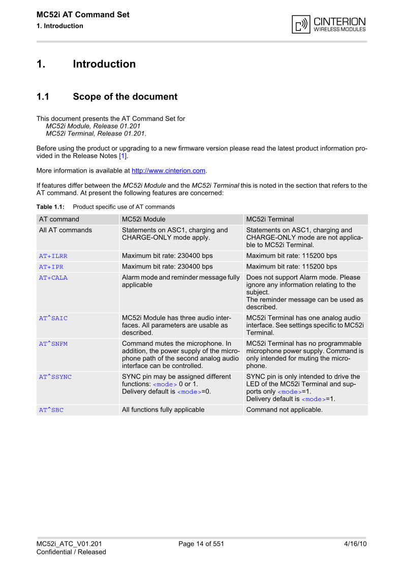
If features differ between the MC52i Module and the MC52i Terminal this is noted in the section that refers to theAT command. At present the following features are concerned:
Table 1.1: Product specific use of AT commands
AT command MC52i Module MC52i Terminal
All AT commands Statements on ASC1, charging and CHARGE-ONLY mode apply.
Statements on ASC1, charging and CHARGE-ONLY mode are not applica-ble to MC52i Terminal.
AT+ILRR Maximum bit rate: 230400 bps Maximum bit rate: 115200 bps
AT+IPR Maximum bit rate: 230400 bps Maximum bit rate: 115200 bps
AT+CALA Alarm mode and reminder message fully applicable
Does not support Alarm mode. Please ignore any information relating to the subject.The reminder message can be used as described.
AT^SAIC MC52i Module has three audio inter-faces. All parameters are usable as described.
MC52i Terminal has one analog audio interface. See settings specific to MC52i Terminal.
AT^SNFM Command mutes the microphone. In addition, the power supply of the micro-phone path of the second analog audio interface can be controlled.
MC52i Terminal has no programmable microphone power supply. Command is only intended for muting the micro-phone.
AT^SSYNC SYNC pin may be assigned different functions: <mode> 0 or 1. Delivery default is <mode>=0.
SYNC pin is only intended to drive the LED of the MC52i Terminal and sup-ports only <mode>=1. Delivery default is <mode>=1.
AT^SBC All functions fully applicable Command not applicable.
MC52i AT Command Set 1.2 Related documents
MC52i_ATC_V01.201 Page 15 of 551 4/16/10Confidential / Released
1.2 Related documents
[1] MC52i Release Notes, Version 01.201
[2] MC52i Hardware Interface Description, Version 01.201
[3] MC52i Terminal Hardware Interface Description
[4] Multiplexer User's Guide
[5] 3GPP TS 27.010 (GSM 07.10): Terminal Equipment to User Equipment (TE-UE) multiplexer protocol
[6] Multiplex Driver Developer's Guide
[7] Multiplex Driver Installation Guide
[8] Application Note 02: Audio Interface Design
[9] Application Note 16: Updating MC52i Firmware
[10] Application Note 22: Using TTY / CTM equipment with MC52i
[11] Application Note 24: Application Developer's Guide
[12] ISO/IEC10646: "Universal Multiple-Octet Coded Character Set (UCS)"; UCS2, 16 bit coding
[13] ITU-T Recommendation V.24: List of definitions for interchange circuits between data terminal equipment(DTE) and data circuit-terminating equipment (DCE)
[14] ITU-T Recommendation V.250: Serial asynchronous automatic dialling and control
[15] 3GPP TS 100 918/EN 300 918 (GSM 02.04): General on supplementary services
[16] 3GPP TS 100 907 (GSM 02.30): Man-Machine Interface (MMI) of the Mobile Station (MS)
[17] 3GPP TS 23.038 (GSM 03.38): Alphabets and language specific information
[18] 3GPP TS 27.005 (GSM 07.05): Use of Data Terminal Equipment - Data Circuit terminating Equipment (DTE- DCE) interface for Short Message Service (SMS) and Cell Broadcast Service (CBS)
[19] 3GPP TS 27.007 (GSM 07.07): AT command set for User Equipment (UE)
[20] 3GPP TS 27.060 (GSM 07.60): Mobile Station (MS) supporting Packet Switched Services
[21] 3GPP TS 51.011 (GSM 11.11): Specification of the Subscriber Identity Module - Mobile Equipment (SIM -ME) interface
[22] 3GPP TS 11.14 (GSM 11.14): Specification of the SIM Application Toolkit for the Subscriber Identity Module- Mobile Equipment (SIM - ME) interface
[23] 3GPP TS 22.101 (GSM 22.101): Service principles
[24] Common PCN Handset Specification (CPHS) v4.2
MC52i AT Command Set 1.3 Document Conventions
MC52i_ATC_V01.201 Page 16 of 551 4/16/10Confidential / Released
1.3 Document Conventions
Throughout this document MC52i is also referred to as GSM Mobile Engine or short ME, MS (Mobile Station),TA (Terminal Adapter), DCE (Data Communication Equipment) or facsimile DCE (FAX modem, FAX board). Ifthe Cinterion product names are required to distinguish the two device types, MC52i is short for the GSM MobileEngine and MC52iT for the GSM Terminal. AT Commands are used to control the MC52i. The controlling device at the other end of the serial line is referredto as Customer Application, TE or DTE (Data Terminal Equipment). All abbreviations and acronyms used throughout this document are based on GSM or 3GPP specifications. Foradditional definitions please refer to TR 100 350 V7.0.0 (1999-08), (GSM 01.04, version 7.0.0 release 1998).
1.3.1 Quick reference table
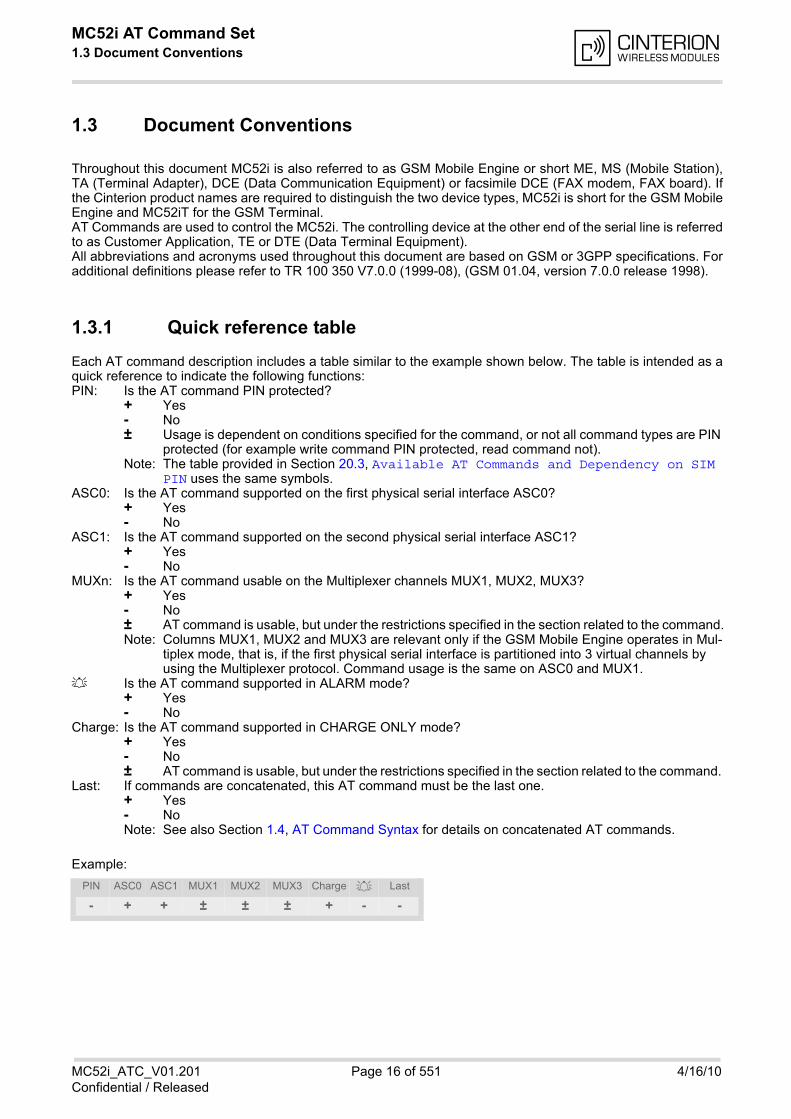
Each AT command description includes a table similar to the example shown below. The table is intended as aquick reference to indicate the following functions:
Example:
PIN: Is the AT command PIN protected? + Yes - No ± Usage is dependent on conditions specified for the command, or not all command types are PIN
protected (for example write command PIN protected, read command not). Note: The table provided in Section 20.3, Available AT Commands and Dependency on SIM
PIN uses the same symbols.ASC0: Is the AT command supported on the first physical serial interface ASC0? + Yes - NoASC1: Is the AT command supported on the second physical serial interface ASC1? + Yes - NoMUXn: Is the AT command usable on the Multiplexer channels MUX1, MUX2, MUX3? + Yes
- No ± AT command is usable, but under the restrictions specified in the section related to the command. Note: Columns MUX1, MUX2 and MUX3 are relevant only if the GSM Mobile Engine operates in Mul-
tiplex mode, that is, if the first physical serial interface is partitioned into 3 virtual channels by using the Multiplexer protocol. Command usage is the same on ASC0 and MUX1.
Is the AT command supported in ALARM mode? + Yes - NoCharge: Is the AT command supported in CHARGE ONLY mode? + Yes - No ± AT command is usable, but under the restrictions specified in the section related to the command. Last: If commands are concatenated, this AT command must be the last one. + Yes - No Note: See also Section 1.4, AT Command Syntax for details on concatenated AT commands.
PIN ASC0 ASC1 MUX1 MUX2 MUX3 Charge Last
- + + ± ± ± + - -
MC52i AT Command Set 1.3 Document Conventions
MC52i_ATC_V01.201 Page 17 of 551 4/16/10Confidential / Released
1.3.2 Superscript notation for parameters and values
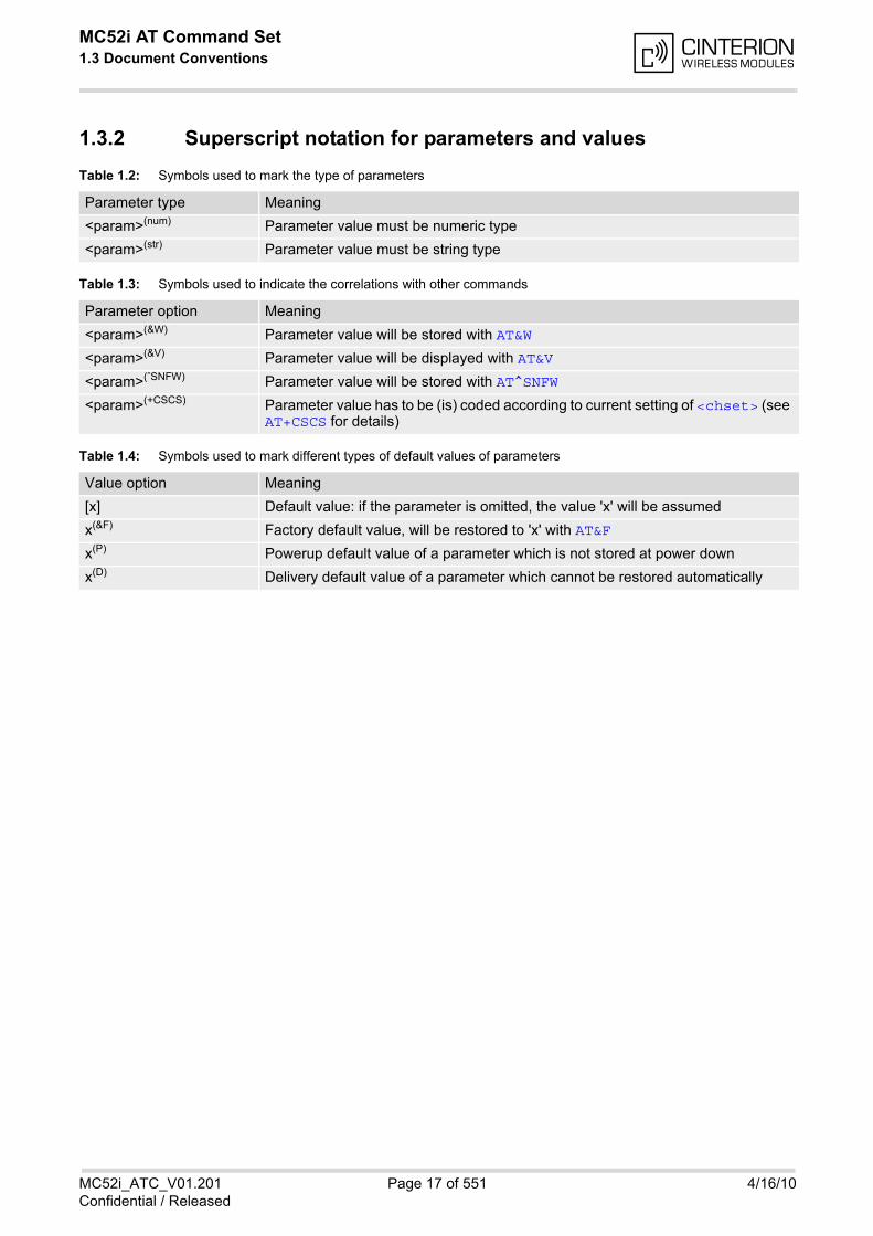
Table 1.2: Symbols used to mark the type of parameters
Table 1.3: Symbols used to indicate the correlations with other commands
Table 1.4: Symbols used to mark different types of default values of parameters
Parameter type Meaning
<param>(num) Parameter value must be numeric type
<param>(str) Parameter value must be string type
Parameter option Meaning
<param>(&W) Parameter value will be stored with AT&W
<param>(&V) Parameter value will be displayed with AT&V
<param>(ˆSNFW) Parameter value will be stored with AT^SNFW
<param>(+CSCS) Parameter value has to be (is) coded according to current setting of <chset> (see AT+CSCS for details)
Value option Meaning
[x] Default value: if the parameter is omitted, the value 'x' will be assumed
x(&F) Factory default value, will be restored to 'x' with AT&F
x(P) Powerup default value of a parameter which is not stored at power down
x(D) Delivery default value of a parameter which cannot be restored automatically
MC52i AT Command Set 1.4 AT Command Syntax
MC52i_ATC_V01.201 Page 18 of 551 4/16/10Confidential / Released
1.4 AT Command Syntax
The "AT" or "at" prefix must be set at the beginning of each command line. To terminate a command line enter<CR>. Commands are usually followed by a response that includes "<CR><LF><response><CR><LF>". Through-out this document, only the responses are presented, <CR><LF> are omitted intentionally.
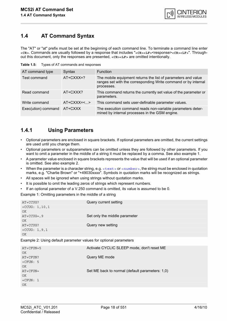
Table 1.5: Types of AT commands and responses
1.4.1 Using Parameters
• Optional parameters are enclosed in square brackets. If optional parameters are omitted, the current settingsare used until you change them.
• Optional parameters or subparameters can be omitted unless they are followed by other parameters. If youwant to omit a parameter in the middle of a string it must be replaced by a comma. See also example 1.
• A parameter value enclosed in square brackets represents the value that will be used if an optional parameteris omitted. See also example 2.
• When the parameter is a character string, e.g. <text> or <number>, the string must be enclosed in quotationmarks, e.g. "Charlie Brown" or "+49030xxxx". Symbols in quotation marks will be recognized as strings.
• All spaces will be ignored when using strings without quotation marks.
• It is possible to omit the leading zeros of strings which represent numbers.
• If an optional parameter of a V.250 command is omitted, its value is assumed to be 0.
Example 1: Omitting parameters in the middle of a string
Example 2: Using default parameter values for optional parameters
AT command type Syntax Function
Test command AT+CXXX=? The mobile equipment returns the list of parameters and value ranges set with the corresponding Write command or by internal processes.
Read command AT+CXXX? This command returns the currently set value of the parameter or parameters.
Write command AT+CXXX=<...> This command sets user-definable parameter values.
Exec(ution) command AT+CXXX The execution command reads non-variable parameters deter-mined by internal processes in the GSM engine.
AT+CCUG? Query current setting+CCUG: 1,10,1OKAT+CCUG=,9 Set only the middle parameterOKAT+CCUG? Query new setting+CCUG: 1,9,1OK
AT+CFUN=5 Activate CYCLIC SLEEP mode, don't reset MEOKAT+CFUN? Query ME mode+CFUN: 5OKAT+CFUN= Set ME back to normal (default parameters: 1,0)OK+CFUN: 1OK
MC52i AT Command Set 1.4 AT Command Syntax
MC52i_ATC_V01.201 Page 19 of 551 4/16/10Confidential / Released
1.4.2 Concatenating AT Commands
Concatenating AT commands on the same line is possible, though not recommended because of restrictionslisted below (for more details see [14]).When concatenating AT commands you need to enter the "AT" or "at" prefix only once at the beginning of a com-mand line. Basic commands (i.e., V.250 commands) are concatenated without delimiter. Extended commands(i.e., commands starting with AT+ or AT^) use a semicolon as delimiter.
Disadvantages and restrictions:
• There is no way to control the minimum time to wait between finishing an AT command and sending the nextone. Please refer to Section 1.5, Communication between Customer Application and MC52i for details abouttiming.
• The sequence of processing the AT commands may be different from the sequential order of command input.
• Many AT commands cannot be concatenated (see list below). Concatenating these commands might end upwith an error result code, or leads to an unexpected order of responses.
AT command type Comment
V.250 commands Cannot be concatenated with FAX commands (prefix AT+F)
GSM 7.07 commands Cannot be concatenated with extended commands (prefix AT^S)
GSM 7.05 commands (SMS) To be used standalone
Commands starting with AT& To be used standalone
AT+IPR To be used standalone
MC52i AT Command Set 1.5 Communication between Customer Application and MC52i
MC52i_ATC_V01.201 Page 20 of 551 4/16/10Confidential / Released
1.5 Communication between Customer Application and MC52i
Leaving hardware flow control unconsidered the Customer Application (TE) is coupled with the MC52i (ME) viaa receive and a transmit line. Since both lines are driven by independent devices collisions may (and will) happen. For example, if the TEissues an AT command the MC52i starts sending a URC. This will probably cause the TE to misinterpret the URCbeing part of the AT command's response. To avoid this conflict the following measures must be taken:
• If an AT command is finished (with "OK" or "ERROR") the TE shall always wait at least 100 ms before sendingthe next one. This applies to bit rates of 9600 bps or higher (see AT+IPR). At bit rates below 9600 bps thedelay must be longer: 300 ms at 1200 bps, and 500 ms at 300 bps. The pause between two AT commands gives the MC52i the opportunity to the transmission of pending URCsand get necessary service. Note that some AT commands may require more delay after "OK" or "ERROR" response, refer to the followingcommand specifications for details.
• The TE shall communicate with the MC52i using activated echo (ATE1), i.e. the MC52i echoes charactersreceived from the TE. Hence, when the TE receives the echo of the first character "A" of the AT command just sent by itself it hascontrol both over the receive and the transmit paths.
Using Backspace at command line:
• As the standard GSM alphabet does not provide a backspace functionality the MC52i is designed to use thecharacter "08" (hex 0x08) as backspace for command line input. This allows the user to easily erase the lastcharacter when writing an AT command. On the other hand, this solution requires entering the escapesequence \08 for writing the "ò" character in GSM character string parameters.
• If command echo is enabled (ATE1) Backspace may cause 08 - 32 - 08 (decimal) character sequence or noecho, depending on serial interface and speed of character input.
Software flow control:
• Regardless of the selected alphabet, keep in mind that, when using software flow control (AT\Q1), charactervalues 17 and 19 (decimal) are interpreted as XON/XOFF control characters.
MC52i AT Command Set 1.6 Supported character sets
MC52i_ATC_V01.201 Page 21 of 551 4/16/10Confidential / Released
1.6 Supported character sets
MC52i supports two character sets: GSM 03.38 (7 bit, also referred to as GSM alphabet or SMS alphabet) andUCS2 (16 bit, refer to ISO/IEC 10646). See AT+CSCS for information about selecting the character set. Charactertables can be found below.
Explanation of terms
• Escape sequenceThe escape sequence used within a text coded in the GSM default alphabet (0x1B) must be correctly inter-preted by the TE, both for character input and output. To the MC52i, an escape sequence appears like anyother byte received or sent.
• TE Character SetThe character set currently used by the Customer Application is selected with AT+CSCS. It is recommendedto select UCS2 setting.
• Data Coding Scheme (DCS)DCS is part of a short message and is saved on the SIM. When writing a short message to the SIM in textmode, the DCS stored with AT+CSMP is used and determines the coded character set.
When you enter characters that are not valid characters of the supported alphabets the behavior is undefined. If GSM alphabet is selected, all characters sent over the serial line (between TE and ME) must be in the rangefrom 0 to 127 (7 bit range). Note: If the ME is configured for GSM alphabet, but the Customer Application (TE) uses ASCII, bear in mind thatsome characters have different code values, such as the following:
• "@" character with GSM alphabet value 0 is not displayable by an ASCII terminal program, e.g. Microsoft©Hyperterminal®.
• "@" character with GSM alphabet value 0 will terminate any C string! This is because value 0 is defined as Cstring end tag. Therefore, the GSM Null character will cause problems on application level when using 'C'-functions, e.g. "strlen()". Using an escape sequence as shown in the table below solves the problem. By theway, this may be the reason why even network providers sometimes replace '@' with "@=*" in their SIM appli-cation.
• Some other characters of the GSM alphabet may be misinterpreted by an ASCII terminal program. For exam-ple, GSM "ö" (as in "Börse") is assumed to be "|" in ASCII, thus resulting in "B|rse". This is because in bothalphabets there are different characters assigned to value 7C (hexadecimal).
If sending characters differently coded or undefined in ASCII or GSM (e.g. Ä, Ö, Ü), use of escape sequences isreasonable. The escape sequence will be translated into the corresponding GSM character value that can becorrectly represented by any program using the GSM alphabet. However, trying to read the same string with anASCII terminal program will display a wrong character.
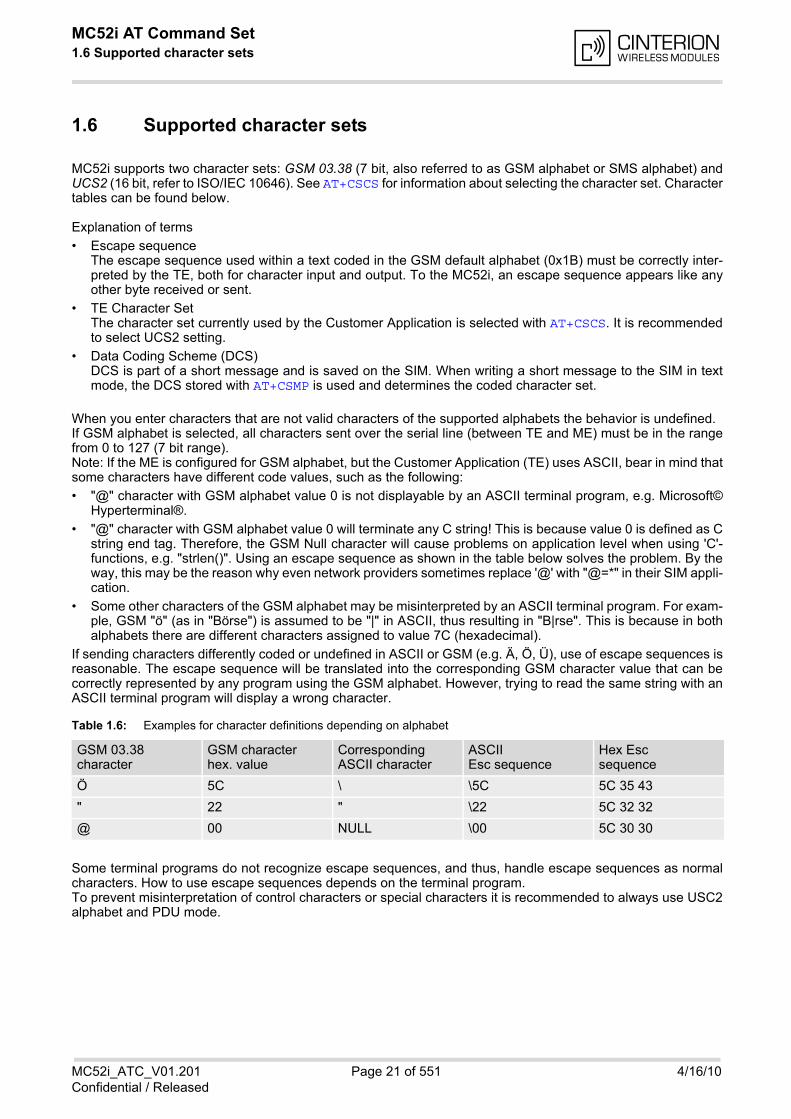
Table 1.6: Examples for character definitions depending on alphabet
Some terminal programs do not recognize escape sequences, and thus, handle escape sequences as normalcharacters. How to use escape sequences depends on the terminal program. To prevent misinterpretation of control characters or special characters it is recommended to always use USC2alphabet and PDU mode.
GSM 03.38character
GSM characterhex. value
CorrespondingASCII character
ASCIIEsc sequence
Hex Escsequence
Ö 5C \ \5C 5C 35 43
" 22 " \22 5C 32 32
@ 00 NULL \00 5C 30 30
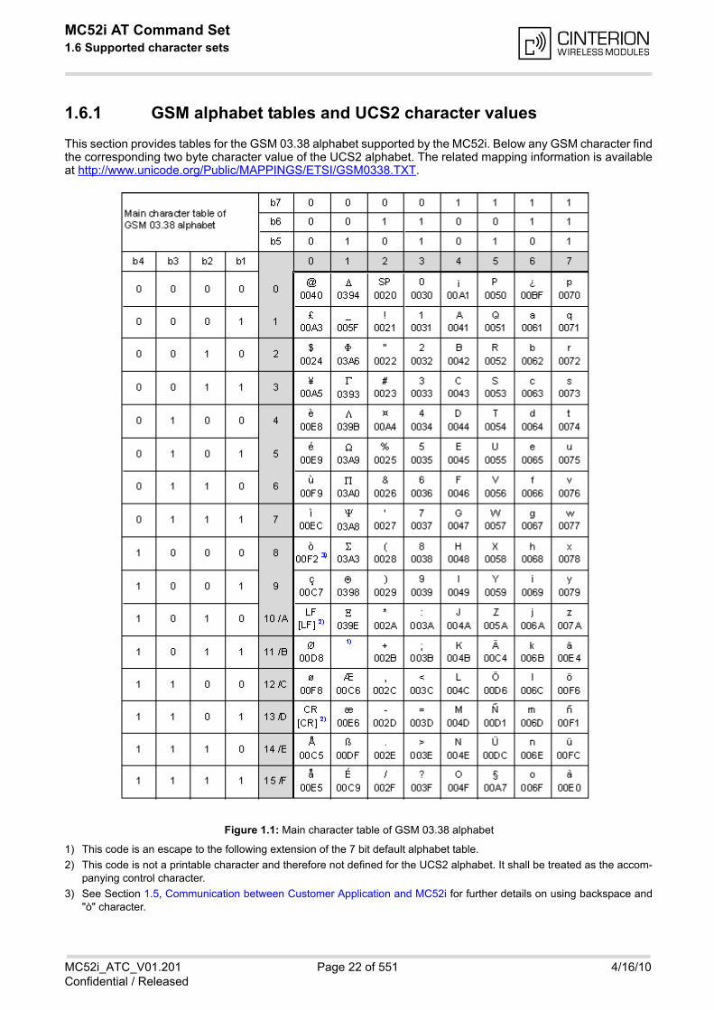
MC52i AT Command Set 1.6 Supported character sets
MC52i_ATC_V01.201 Page 22 of 551 4/16/10Confidential / Released
1.6.1 GSM alphabet tables and UCS2 character values
This section provides tables for the GSM 03.38 alphabet supported by the MC52i. Below any GSM character findthe corresponding two byte character value of the UCS2 alphabet. The related mapping information is availableat http://www.unicode.org/Public/MAPPINGS/ETSI/GSM0338.TXT.
1) This code is an escape to the following extension of the 7 bit default alphabet table.
2) This code is not a printable character and therefore not defined for the UCS2 alphabet. It shall be treated as the accom-panying control character.
3) See Section 1.5, Communication between Customer Application and MC52i for further details on using backspace and"ò" character.
Figure 1.1: Main character table of GSM 03.38 alphabet
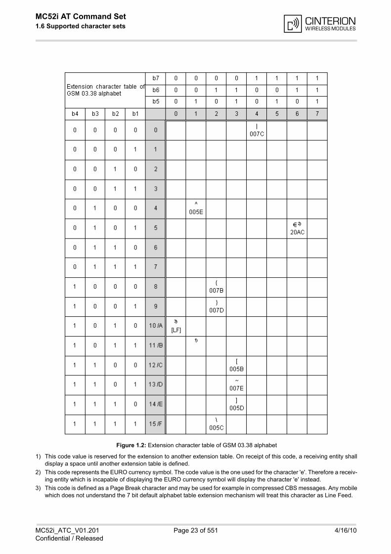
MC52i AT Command Set 1.6 Supported character sets
MC52i_ATC_V01.201 Page 23 of 551 4/16/10Confidential / Released
1) This code value is reserved for the extension to another extension table. On receipt of this code, a receiving entity shalldisplay a space until another extension table is defined.
2) This code represents the EURO currency symbol. The code value is the one used for the character 'e'. Therefore a receiv-ing entity which is incapable of displaying the EURO currency symbol will display the character 'e' instead.
3) This code is defined as a Page Break character and may be used for example in compressed CBS messages. Any mobilewhich does not understand the 7 bit default alphabet table extension mechanism will treat this character as Line Feed.
Figure 1.2: Extension character table of GSM 03.38 alphabet
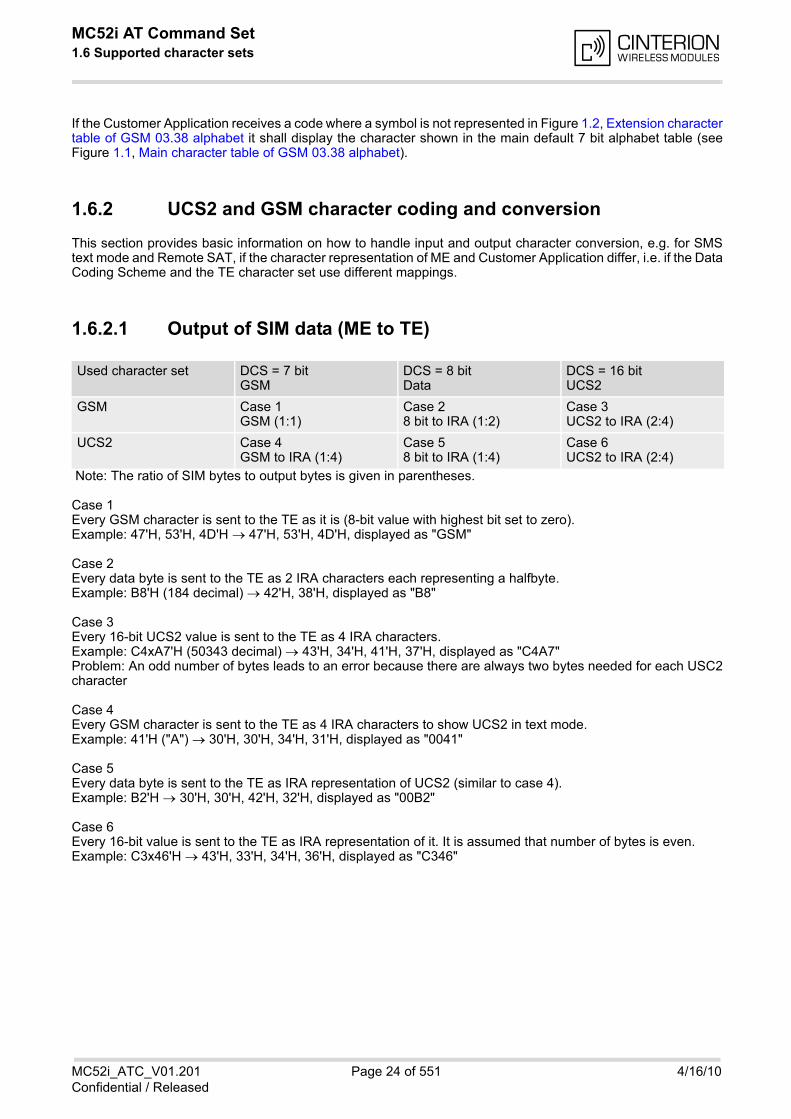
MC52i AT Command Set 1.6 Supported character sets
MC52i_ATC_V01.201 Page 24 of 551 4/16/10Confidential / Released
If the Customer Application receives a code where a symbol is not represented in Figure 1.2, Extension charactertable of GSM 03.38 alphabet it shall display the character shown in the main default 7 bit alphabet table (seeFigure 1.1, Main character table of GSM 03.38 alphabet).
1.6.2 UCS2 and GSM character coding and conversion
This section provides basic information on how to handle input and output character conversion, e.g. for SMStext mode and Remote SAT, if the character representation of ME and Customer Application differ, i.e. if the DataCoding Scheme and the TE character set use different mappings.
1.6.2.1 Output of SIM data (ME to TE)
Note: The ratio of SIM bytes to output bytes is given in parentheses.
Case 1Every GSM character is sent to the TE as it is (8-bit value with highest bit set to zero).Example: 47'H, 53'H, 4D'H 47'H, 53'H, 4D'H, displayed as "GSM"
Case 2Every data byte is sent to the TE as 2 IRA characters each representing a halfbyte.Example: B8'H (184 decimal) 42'H, 38'H, displayed as "B8"
Case 3Every 16-bit UCS2 value is sent to the TE as 4 IRA characters.Example: C4xA7'H (50343 decimal) 43'H, 34'H, 41'H, 37'H, displayed as "C4A7"Problem: An odd number of bytes leads to an error because there are always two bytes needed for each USC2character
Case 4Every GSM character is sent to the TE as 4 IRA characters to show UCS2 in text mode.Example: 41'H ("A") 30'H, 30'H, 34'H, 31'H, displayed as "0041"
Case 5Every data byte is sent to the TE as IRA representation of UCS2 (similar to case 4).Example: B2'H 30'H, 30'H, 42'H, 32'H, displayed as "00B2"
Case 6Every 16-bit value is sent to the TE as IRA representation of it. It is assumed that number of bytes is even.Example: C3x46'H 43'H, 33'H, 34'H, 36'H, displayed as "C346"
Used character set DCS = 7 bitGSM
DCS = 8 bitData
DCS = 16 bitUCS2
GSM Case 1GSM (1:1)
Case 28 bit to IRA (1:2)
Case 3UCS2 to IRA (2:4)
UCS2 Case 4GSM to IRA (1:4)
Case 58 bit to IRA (1:4)
Case 6UCS2 to IRA (2:4)
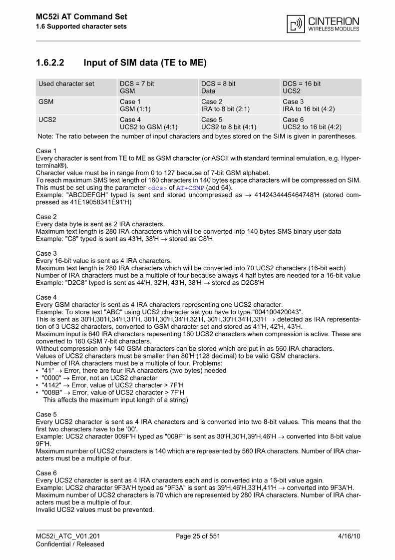
MC52i AT Command Set 1.6 Supported character sets
MC52i_ATC_V01.201 Page 25 of 551 4/16/10Confidential / Released
1.6.2.2 Input of SIM data (TE to ME)
Note: The ratio between the number of input characters and bytes stored on the SIM is given in parentheses.
Case 1Every character is sent from TE to ME as GSM character (or ASCII with standard terminal emulation, e.g. Hyper-terminal®).Character value must be in range from 0 to 127 because of 7-bit GSM alphabet.To reach maximum SMS text length of 160 characters in 140 bytes space characters will be compressed on SIM.This must be set using the parameter <dcs> of AT+CSMP (add 64).Example: "ABCDEFGH" typed is sent and stored uncompressed as 4142434445464748'H (stored com-pressed as 41E19058341E91'H)
Case 2Every data byte is sent as 2 IRA characters.Maximum text length is 280 IRA characters which will be converted into 140 bytes SMS binary user dataExample: "C8" typed is sent as 43'H, 38'H stored as C8'H
Case 3Every 16-bit value is sent as 4 IRA characters.Maximum text length is 280 IRA characters which will be converted into 70 UCS2 characters (16-bit each)Number of IRA characters must be a multiple of four because always 4 half bytes are needed for a 16-bit valueExample: "D2C8" typed is sent as 44'H, 32'H, 43'H, 38'H stored as D2C8'H
Case 4Every GSM character is sent as 4 IRA characters representing one UCS2 character.Example: To store text "ABC" using UCS2 character set you have to type "004100420043".This is sent as 30'H,30'H,34'H,31'H, 30'H,30'H,34'H,32'H, 30'H,30'H,34'H,33'H detected as IRA representa-tion of 3 UCS2 characters, converted to GSM character set and stored as 41'H, 42'H, 43'H.Maximum input is 640 IRA characters repesenting 160 UCS2 characters when compression is active. These areconverted to 160 GSM 7-bit characters.Without compression only 140 GSM characters can be stored which are put in as 560 IRA characters.Values of UCS2 characters must be smaller than 80'H (128 decimal) to be valid GSM characters.Number of IRA characters must be a multiple of four. Problems:• "41" Error, there are four IRA characters (two bytes) needed• "0000" Error, not an UCS2 character• "4142" Error, value of UCS2 character > 7F'H• "008B" Error, value of UCS2 character > 7F'H This affects the maximum input length of a string)
Case 5Every UCS2 character is sent as 4 IRA characters and is converted into two 8-bit values. This means that thefirst two characters have to be '00'.Example: UCS2 character 009F'H typed as "009F" is sent as 30'H,30'H,39'H,46'H converted into 8-bit value9F'H.Maximum number of UCS2 characters is 140 which are represented by 560 IRA characters. Number of IRA char-acters must be a multiple of four.
Case 6Every UCS2 character is sent as 4 IRA characters each and is converted into a 16-bit value again.Example: UCS2 character 9F3A'H typed as "9F3A" is sent as 39'H,46'H,33'H,41'H converted into 9F3A'H.Maximum number of UCS2 characters is 70 which are represented by 280 IRA characters. Number of IRA char-acters must be a multiple of four.Invalid UCS2 values must be prevented.
Used character set DCS = 7 bitGSM
DCS = 8 bitData
DCS = 16 bitUCS2
GSM Case 1GSM (1:1)
Case 2IRA to 8 bit (2:1)
Case 3IRA to 16 bit (4:2)
UCS2 Case 4UCS2 to GSM (4:1)
Case 5UCS2 to 8 bit (4:1)
Case 6UCS2 to 16 bit (4:2)
MC52i AT Command Set 1.7 Unsolicited Result Code Presentation
MC52i_ATC_V01.201 Page 26 of 551 4/16/10Confidential / Released
1.7 Unsolicited Result Code Presentation
URC stands for Unsolicited Result Code and is a report message issued by the ME without being requested bythe TE, i.e. a URC is issued automatically when a certain event occurs. Hence, a URC is not issued as part ofthe response related to an executed AT command. Typical events leading to URCs are incoming calls ("RING"), waiting calls, received short messages, changes intemperature, network registration etc. A list of all URCs can be found in Section 20.7, Summary of Unsolicited Result Codes (URC).
To announce a pending URC transmission the ME will do the following:
• The ME activates its RING line (logic "1") for 1 second, i.e. the RING line changes to the physical "Low" level.This allows the TE to stay in power saving mode until an ME related event requests service. If several URCs occur coincidently or in quick succession each URC triggers the RING line independently,although the line will not be deactivated between each URC. As a result, the RING line may stay low for morethan 1 second. If an incoming call is answered within less than 1 second (with ATA or if autoanswering is set to ATS0=1) thanthe RING line will be deactivated earlier.The "^SHUTDOWN" URC will not activate the RING line.
• If the AT command interface is busy a "BREAK" will be sent immediately but the URC will not be issued untilthe line is free. This may happen if the URC is pending in the following cases:
- During the processing of an AT command (i.e. the time after the TE echoes back the first character "A" ofan AT command just sent by itself until the ME responds with "OK" or "ERROR").
- During a data call.
Please note that AT command settings may be necessary to enable in-band signaling, e.g. refer to AT+CMERor AT+CNMI.
It is strongly recommended to use the multiplex mode to map logical communication channels onto the serial lineof the MC52i, for details refer to [4] and AT command AT+CMUX. Doing so it is possible to use one channel to stillprocess URCs while having a data call active on another.For most of these messages, the ME needs to be configured whether or not to send a URC. Depending on theAT command, the URC presentation mode can be saved to the user defined profile (see AT&W), or needs to beactivated every time you reboot the ME. Several URCs are not user definable, such as "^SYSSTART","^SYSSTART <text>", "^SHUTDOWN" and the Fax Class 2 URCs listed in Section 12.1, FAX parameters. If autobauding is enabled (as factory default mode or set with AT+IPR=0), URCs generated after restart will beoutput with 57600 bps until the ME has detected the current bit rate. The URCs "^SYSSTART", "^SYSSTART<text>", however, are not presented at all. For details please refer to Section 4.7.1, Autobauding. To avoid prob-lems we recommend to configure a fixed bit rate rather than using autobauding.
MC52i AT Command Set 1.8 Errors and Messages
MC52i_ATC_V01.201 Page 27 of 551 4/16/10Confidential / Released
1.8 Errors and Messages
The command result codes "+CME ERROR: <err>" and "+CMS ERROR: <err>" indicate errors related to mobileequipment or network functionality.
The format of <err> can be either numeric or verbose and is selectable via AT+CMEE.
A result error code terminates the execution of the command and prevents the execution of all remaining com-mands that may follow on the same command line. If so, neither "ERROR" nor "OK" result codes are returnedfor these commands. A 30 seconds timeout will deliver "ERROR" when the input of a command is not complete.
Using the wrong command syntax may result in errors: For example, using the execute command syntaxalthough the command has no execute format, causes "ERROR" to be returned. Likewise, using the write com-mand syntax although the command has no write format causes "+CME ERROR: <err>" to be returned.
See also:
• Section 2.11.1, CME/CMS Error Code Overview
• Section 2.5.1, Verbose and numeric result codes
• Section 3.4, AT+CEER
MC52i AT Command Set 1.9 Auxiliary Serial Interface
MC52i_ATC_V01.201 Page 28 of 551 4/16/10Confidential / Released
1.9 Auxiliary Serial Interface
The second serial interface (ASC1) is designed as an additional interface for applications which need multipleparallel access to the MC52i, e.g. to query status information while a data connection is in progress on ASC0.However, the auxiliary interface provides only limited functionality:
• Multiplex mode via AT+CMUX is not supported.
• DTR, DSR, DCD, RING hardware lines do not exist. AT commands for controlling the behavior of these lines(AT&D, AT&C, AT&S) are not allowed and return ERROR.
• No presentation of ^SYSSTART URCs. After restart or reset of the ME, either check that the URC has beensent on ASC0 or wait approximately 3 seconds before entering the first AT command on ASC1.
• No CSD calls, so all related AT commands cannot be used and return ERROR, such as AT+CBST, ATS7,AT+CRLP.
• No fax calls, so all AT+F commands cannot be used and return ERROR.
• When you set up packet switched connections take care that your application uses only AT commands,parameters and signal lines supported on the ASC1 interface. For example, keep in mind that Microsoft Dial-up connections are typically trying to request the DCD line status and that common modem drivers use tosend commands such as AT+CBST or ATS7, which may not be supported.
• No Autobauding. The hardware is not capable of automatically detecting the baudrate on this interface, sothe AT command which selects autobauding (AT+IPR=0) is not allowed and returns ERROR.
ASC1 is disabled when the multiplexer is enabled on the first serial interface ASC0. Yet, both ASC1 and the mul-tiplexer channel 2 are using the same parameters, and thus, the same user defined profile (if any). As a result,a user profile stored on multiplexer channel 2 takes effect on ASC1 after closing the multiplexer and starting upASC1. Likewise, a user profile stored on ASC1 will be loaded on multiplexer channel 2.This may be a problem when ASC1 is not connected, but flow control (for example AT\Q1 or AT\Q3) is stored tothe user profile on the multiplexer channel 2. In this case, flow control takes effect on ASC1, when the multiplexeris switched off. If then for example a large amount of URCs is generated, their transmission might be stoppeddue to the flow control. To avoid this problem we recommend that you do not activate flow control on multiplexerchannel 2 when you set up a user profile with AT&W.
MC52i AT Command Set 1.10 Serial Interface Flow Control
MC52i_ATC_V01.201 Page 29 of 551 4/16/10Confidential / Released
1.10 Serial Interface Flow Control
Flow control is essential to prevent loss of data or avoid errors when, in a data or fax call, the sending device istransferring data faster than the receiving side is ready to accept. When the receiving buffer reaches its capacity,the receiving device should be capable to cause the sending device to pause until it catches up. There are basically two approaches to regulate data flow: Software flow control and hardware flow control. TheHigh Watermark (HWM) of the input/output buffer should be set to approximately 60% of the total buffer size, theLow Watermark (LWM) is recommended to be about 30%. The data flow should be stopped when the buffercapacity rises close to the High Watermark and resumed when it drops below the Low Watermark. The timerequired to cause stop and go results in a hysteresis between the High and Low Watermarks.
1.10.1 Software Flow Control (XON/OFF Handshake)
Software flow control can be used to control the data flow in both directions from DTE to MC52i and from MC52ito DTE. Software flow control uses different characters to stop (XOFF, decimal 19) and resume (XON, decimal17) data flow. Hence, all data that represent XON or XOFF characters will be interpreted as control characters.This applies also to characters included within the data stream to be transmitted (usually plain ASCII text files donot inlude such characters). The only advantage of software flow control is that three wires would be sufficienton the serial interface.
1.10.2 Hardware Flow Control (RTS/CTS Handshake)
Hardware flow control sets or resets the RTS/CTS wires. This approach is faster and more reliable, and there-fore, the better choice. When the HWM is reached, CTS is set inactive. When the LWM is passed, CTS goesactive again. To achieve smooth data flow, ensure that the RTS/CTS lines are present on your application plat-form.
Configuring hardware flow control
• Hardware flow control must be set on both sides: with AT\Q3 in the ME and an equivalent RTS/CTS hand-shake option in the host application.
• The default setting of the ME is AT\Q0 (no flow control) which must be altered to AT\Q3 (RTS/CTS hardwarehandshake on). The setting is stored volatile and must be restored each time after rebooting the ME.
• AT\Q has no read command. To verify the current setting of AT\Q, simply check the settings of the activeprofile with AT&V.
• Often, fax programs run an intialization procedure when started up. The intialization commonly includesenabling RTS/CTS hardware handshake, eliminating the need to set AT\Q3 once again. However, before set-ting up a CSD call, you are advised to check that RTS/CTS handshake is set.
Buffer design considerations
• After deactivating the RTS line, the ME may still send up to 264 bytes (worst case). This can be easily handledif the buffer of the host application is sufficiently sized, and if a hysteresis is implemented regarding its Rxbuffer. For host applications that are required to handle a large amount of data at high speed, a total buffercapacity of 512 bytes is recommended.
MC52i AT Command Set 1.11 Common PCN Handset Specification (CPHS)
MC52i_ATC_V01.201 Page 30 of 551 4/16/10Confidential / Released
1.11 Common PCN Handset Specification (CPHS)
The ME provides features to implement a device following the prerequisites of the Common PCN Handset Spec-ification (CPHS) Phase 2.
CPHS Feature Description/Remarks AT command
Alternate Line Service Using two phone numbers with one SIM card. AT^SALS
Voice Message Waiting Indication
Indicate the receipt of a short message coded as Voice Mes-sage Waiting Indicator as defined by the CPHS Phase 2 standard.
AT^SIND, AT+CMER, indicators "vmwait1" and "vmwait2"
Operator (Service pro-vider) name from SIM
Read specific Elementary Files (6F14h, 6F18h) from SIM. AT+CRSM
Network and Service Pro-vider Lock
Lock/Unlock an ME to specific HPLMN and service provider. AT+CLCK, (AT+CPIN)
Call Forwarding Get and set diverted call status. Access specific Elementary File (6F13h) from SIM.
AT+CCFC, AT+CRSM
Customer Service Profile (CSP)
Setting services and their menu entries depending on cus-tomer profiles.
AT+CRSM
Information numbers Hierarchically structured service numbers phonebook on SIM according to CPHS 4.2 (mandatory).
AT+CRSM

MC52i AT Command Set 2. Configuration Commands
MC52i_ATC_V01.201 Page 31 of 551 4/16/10Confidential / Released
2. Configuration Commands
The AT Commands described in this chapter allow the external application to determine the MC52i's behaviourunder various conditions.
2.1 AT&F Set all current parameters to manufacturer defaults
AT&F sets all current parameters to the manufacturer defined profile. All defined GPRS contexts which are notactivated or not online will be undefined (see AT+CGDCONT).
Syntax
Parameter Description
[0] Set all TA parameters to manufacturer defaults
Notes• List of parameters reset to manufacturer default can be found in Section 20.6, Factory Default Set-
tings Restorable with AT&F.
• In addition to the default profile, you can store an individual one with AT&W. To alternate between the two pro-files enter either ATZ (loads user profile) or AT&F (restores factory profile).
• Every ongoing or incoming call will be terminated.
Exec Command
AT&F[<value>]Response(s)
OK
PIN ASC0 ASC1 MUX1 MUX2 MUX3 Charge Last Reference(s)
- + + + + + - - - V.250
<value>(num)
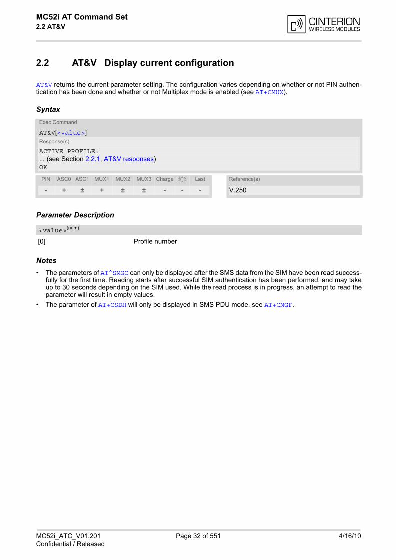
MC52i AT Command Set 2.2 AT&V
MC52i_ATC_V01.201 Page 32 of 551 4/16/10Confidential / Released
2.2 AT&V Display current configuration
AT&V returns the current parameter setting. The configuration varies depending on whether or not PIN authen-tication has been done and whether or not Multiplex mode is enabled (see AT+CMUX).
Syntax
Parameter Description
[0] Profile number
Notes• The parameters of AT^SMGO can only be displayed after the SMS data from the SIM have been read success-
fully for the first time. Reading starts after successful SIM authentication has been performed, and may takeup to 30 seconds depending on the SIM used. While the read process is in progress, an attempt to read theparameter will result in empty values.
• The parameter of AT+CSDH will only be displayed in SMS PDU mode, see AT+CMGF.
Exec Command
AT&V[<value>]Response(s)
ACTIVE PROFILE:... (see Section 2.2.1, AT&V responses)OK
PIN ASC0 ASC1 MUX1 MUX2 MUX3 Charge Last Reference(s)
- + ± + ± ± - - - V.250
<value>(num)

MC52i AT Command Set 2.2 AT&V
MC52i_ATC_V01.201 Page 33 of 551 4/16/10Confidential / Released
2.2.1 AT&V responses
The following tables show four different kinds of responses depending on whether or not the PIN is entered andwhether or not the Multiplex mode is enabled (see AT+CMUX).
Table 2.1: Current configuration on ASC0 / MUX channel 1 (example)
Table 2.2: Current configuration on ASC1 and MUX channels 2 and 3 (example)
PIN authentication done No PIN authentication
ACTIVE PROFILE:E1 Q0 V1 X4 &C1 &D2 &S0 \Q0 S0:000 S3:013 S4:010 S5:008 S6:000 S7:060 S8:000 S10:002 S18:000+CBST: 7,0,1+CRLP: 61,61,78,6+CR: 0+FCLASS: 0+CRC: 0+CMGF: 1+CSDH: 0+CNMI: 0,0,0,0,1+ILRR: 0+IPR: 57600+CMEE: 2^SMGO: 0,0+CSMS: 0,1,1,1^SACM: 0,"000000","000000"^SLCC: 0^SCKS: 0,1+CREG: 0,1+CLIP: 0,2+CAOC: 0+COPS: 0,0,"operator"+CGSMS: 3OK
ACTIVE PROFILE:E1 Q0 V1 X4 &C1 &D2 &S0 \Q0 S0:000 S3:013 S4:010 S5:008 S6:000 S7:060 S8:000 S10:002 S18:000+CBST: 7,0,1+CRLP: 61,61,78,6+CR: 0+FCLASS: 0+ILRR: 0+IPR: 57600+CMEE: 2^SCKS: 0,1OK
PIN authentication done No PIN authentication
ACTIVE PROFILE:E1 Q0 V1 X4 &C1 &D0 &S0 \Q0 S0:000 S3:013 S4:010 S5:008+CR: 0+CRC: 0+CMGF: 1+CSDH: 0+CNMI: 0,0,0,0,1+ILRR: 0+IPR: 57600+CMEE: 2^SMGO: 0,0+CSMS: 0,1,1,1^SACM: 0,"000000","000000"^SLCC: 0^SCKS: 0,1+CREG: 0,1+CLIP: 0,2+CAOC: 0+COPS: 0,0,"operator"+CGSMS: 3OK
ACTIVE PROFILE:E1 Q0 V1 X4 &C1 &D0 &S0 \Q0 S0:000 S3:013 S4:010 S5:008+CR: 0+ILRR: 0+IPR: 57600+CMEE: 2^SCKS: 0,1+CGSMS: 3OK
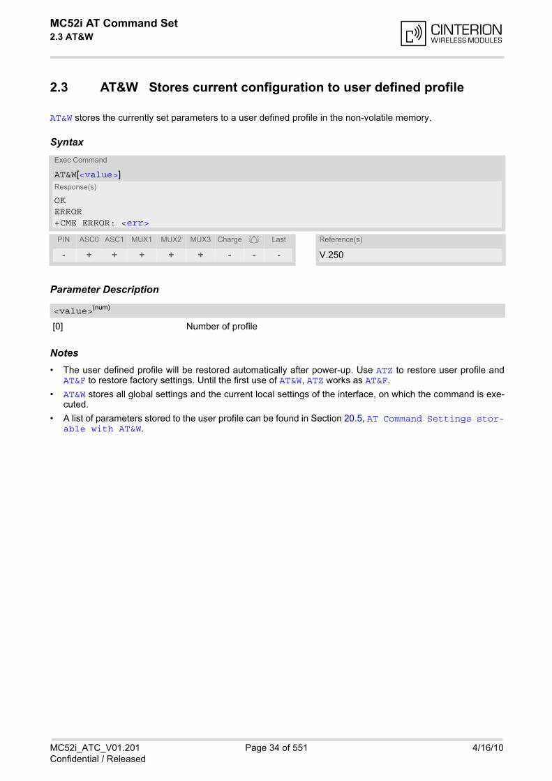
MC52i AT Command Set 2.3 AT&W
MC52i_ATC_V01.201 Page 34 of 551 4/16/10Confidential / Released
2.3 AT&W Stores current configuration to user defined profile
AT&W stores the currently set parameters to a user defined profile in the non-volatile memory.
Syntax
Parameter Description
[0] Number of profile
Notes• The user defined profile will be restored automatically after power-up. Use ATZ to restore user profile and
AT&F to restore factory settings. Until the first use of AT&W, ATZ works as AT&F.
• AT&W stores all global settings and the current local settings of the interface, on which the command is exe-cuted.
• A list of parameters stored to the user profile can be found in Section 20.5, AT Command Settings stor-able with AT&W.
Exec Command
AT&W[<value>]Response(s)
OKERROR+CME ERROR: <err>
PIN ASC0 ASC1 MUX1 MUX2 MUX3 Charge Last Reference(s)
- + + + + + - - - V.250
<value>(num)
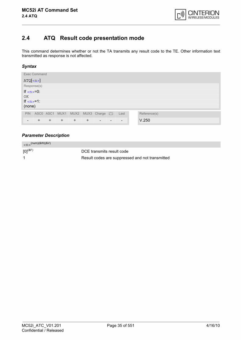
MC52i AT Command Set 2.4 ATQ
MC52i_ATC_V01.201 Page 35 of 551 4/16/10Confidential / Released
2.4 ATQ Result code presentation mode
This command determines whether or not the TA transmits any result code to the TE. Other information texttransmitted as response is not affected.
Syntax
Parameter Description
[0](&F) DCE transmits result code
1 Result codes are suppressed and not transmitted
Exec Command
ATQ[<n>]Response(s)
If <n>=0:OKIf <n>=1:(none)
PIN ASC0 ASC1 MUX1 MUX2 MUX3 Charge Last Reference(s)
- + + + + + - - - V.250
<n>(num)(&W)(&V)

MC52i AT Command Set 2.5 ATV
MC52i_ATC_V01.201 Page 36 of 551 4/16/10Confidential / Released
2.5 ATV Result code format mode
This command determines the contents of header and trailer transmitted with AT command result codes andinformation responses. Possible responses are described in Section 2.5.1, Verbose and numeric result codes.
Syntax
Parameter Description
[0] Information response: <text><CR><LF>Short result code format: <numeric code><CR>
1(&F) Information response: <CR><LF><text><CR><LF>Long result code format: <CR><LF><verbose code><CR>
2.5.1 Verbose and numeric result codes
Exec Command
ATV[<value>]Response(s)
OKERROR
PIN ASC0 ASC1 MUX1 MUX2 MUX3 Charge Last Reference(s)
- + + + + + - - - V.250
<value>(num)(&W)(&V)
Verbose format Numeric format Meaning
OK 0 command executed, no errors
CONNECT 1 link established
RING 2 ring detected
NO CARRIER 3 link not established or disconnected
ERROR 4 invalid command or command line too long
NO DIALTONE 6 no dial tone, dialling impossible, wrong mode
BUSY 7 remote station busy
CONNECT 2400/RLP 47 link with 2400 bps and Radio Link Protocol
CONNECT 4800/RLP 48 link with 4800 bps and Radio Link Protocol
CONNECT 9600/RLP 49 link with 9600 bps and Radio Link Protocol
CONNECT 14400/RLP 50 link with 14400 bps and Radio Link Protocol
ALERTING alerting at called phone
DIALING mobile phone is dialing
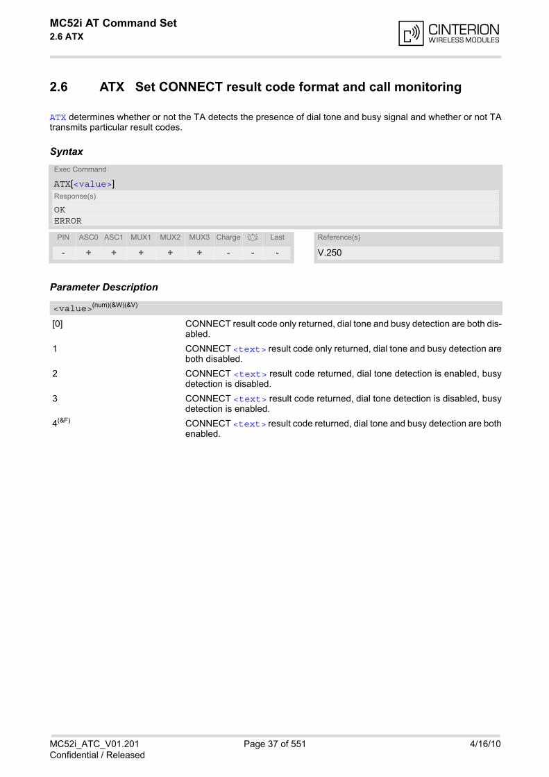
MC52i AT Command Set 2.6 ATX
MC52i_ATC_V01.201 Page 37 of 551 4/16/10Confidential / Released
2.6 ATX Set CONNECT result code format and call monitoring
ATX determines whether or not the TA detects the presence of dial tone and busy signal and whether or not TAtransmits particular result codes.
Syntax
Parameter Description
[0] CONNECT result code only returned, dial tone and busy detection are both dis-abled.
1 CONNECT <text> result code only returned, dial tone and busy detection areboth disabled.
2 CONNECT <text> result code returned, dial tone detection is enabled, busydetection is disabled.
3 CONNECT <text> result code returned, dial tone detection is disabled, busydetection is enabled.
4(&F) CONNECT <text> result code returned, dial tone and busy detection are bothenabled.
Exec Command
ATX[<value>]Response(s)
OKERROR
PIN ASC0 ASC1 MUX1 MUX2 MUX3 Charge Last Reference(s)
- + + + + + - - - V.250
<value>(num)(&W)(&V)
MC52i AT Command Set 2.7 ATZ
MC52i_ATC_V01.201 Page 38 of 551 4/16/10Confidential / Released
2.7 ATZ Set all current parameters to user defined profile
ATZ sets all current parameters to the user profile stored with AT&W. If a connection is in progress, it will be ter-minated.All defined GPRS contexts which are not activated or not online will be undefined (see AT+CGDCONT).The user defined profile is stored to the non-volatile memory.
Syntax
Parameter Description
[0] Reset to user profile
Notes• First the profile will be set to factory default (see AT&F). If there is a valid user profile (stored with AT&W), this
profile will be loaded afterwards.
• Any additional commands on the same command line may be ignored. A delay of 300 ms is required beforenext command is sent, otherwise "OK" response may be corrupted.
Exec Command
ATZ[<value>]Response(s)
OK
PIN ASC0 ASC1 MUX1 MUX2 MUX3 Charge Last Reference(s)
- + + + + + - - - V.250
<value>(num)
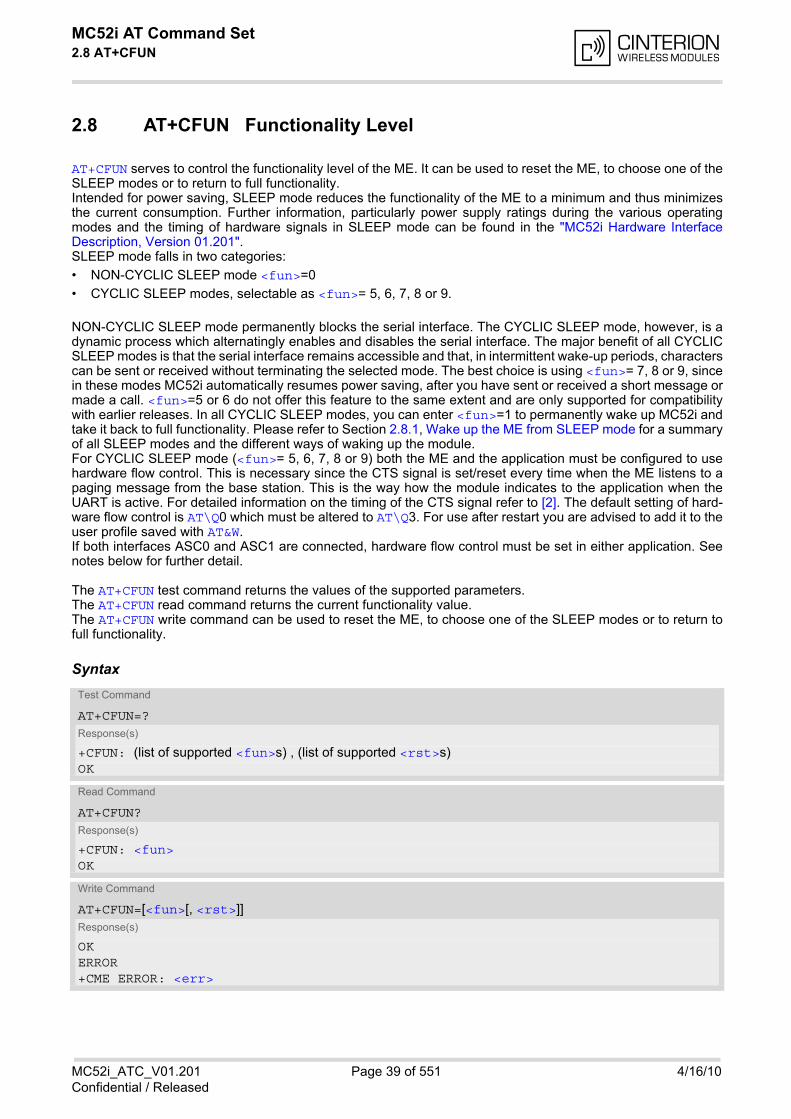
MC52i AT Command Set 2.8 AT+CFUN
MC52i_ATC_V01.201 Page 39 of 551 4/16/10Confidential / Released
2.8 AT+CFUN Functionality Level
AT+CFUN serves to control the functionality level of the ME. It can be used to reset the ME, to choose one of theSLEEP modes or to return to full functionality.Intended for power saving, SLEEP mode reduces the functionality of the ME to a minimum and thus minimizesthe current consumption. Further information, particularly power supply ratings during the various operatingmodes and the timing of hardware signals in SLEEP mode can be found in the "MC52i Hardware InterfaceDescription, Version 01.201". SLEEP mode falls in two categories:
• NON-CYCLIC SLEEP mode <fun>=0
• CYCLIC SLEEP modes, selectable as <fun>= 5, 6, 7, 8 or 9.
NON-CYCLIC SLEEP mode permanently blocks the serial interface. The CYCLIC SLEEP mode, however, is adynamic process which alternatingly enables and disables the serial interface. The major benefit of all CYCLICSLEEP modes is that the serial interface remains accessible and that, in intermittent wake-up periods, characterscan be sent or received without terminating the selected mode. The best choice is using <fun>= 7, 8 or 9, sincein these modes MC52i automatically resumes power saving, after you have sent or received a short message ormade a call. <fun>=5 or 6 do not offer this feature to the same extent and are only supported for compatibilitywith earlier releases. In all CYCLIC SLEEP modes, you can enter <fun>=1 to permanently wake up MC52i andtake it back to full functionality. Please refer to Section 2.8.1, Wake up the ME from SLEEP mode for a summaryof all SLEEP modes and the different ways of waking up the module.For CYCLIC SLEEP mode (<fun>= 5, 6, 7, 8 or 9) both the ME and the application must be configured to usehardware flow control. This is necessary since the CTS signal is set/reset every time when the ME listens to apaging message from the base station. This is the way how the module indicates to the application when theUART is active. For detailed information on the timing of the CTS signal refer to [2]. The default setting of hard-ware flow control is AT\Q0 which must be altered to AT\Q3. For use after restart you are advised to add it to theuser profile saved with AT&W. If both interfaces ASC0 and ASC1 are connected, hardware flow control must be set in either application. Seenotes below for further detail.
The AT+CFUN test command returns the values of the supported parameters. The AT+CFUN read command returns the current functionality value. The AT+CFUN write command can be used to reset the ME, to choose one of the SLEEP modes or to return tofull functionality.
SyntaxTest Command
AT+CFUN=?Response(s)
+CFUN: (list of supported <fun>s) , (list of supported <rst>s)OK
Read Command
AT+CFUN?Response(s)
+CFUN: <fun>OK
Write Command
AT+CFUN=[<fun>[, <rst>]]Response(s)
OKERROR+CME ERROR: <err>
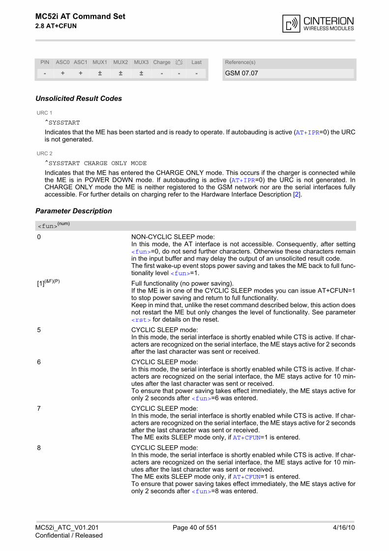
MC52i AT Command Set 2.8 AT+CFUN
MC52i_ATC_V01.201 Page 40 of 551 4/16/10Confidential / Released
Unsolicited Result Codes
URC 1
^SYSSTART
Indicates that the ME has been started and is ready to operate. If autobauding is active (AT+IPR=0) the URCis not generated.
URC 2
^SYSSTART CHARGE ONLY MODE
Indicates that the ME has entered the CHARGE ONLY mode. This occurs if the charger is connected whilethe ME is in POWER DOWN mode. If autobauding is active (AT+IPR=0) the URC is not generated. InCHARGE ONLY mode the ME is neither registered to the GSM network nor are the serial interfaces fullyaccessible. For further details on charging refer to the Hardware Interface Description [2].
Parameter Description
0 NON-CYCLIC SLEEP mode: In this mode, the AT interface is not accessible. Consequently, after setting<fun>=0, do not send further characters. Otherwise these characters remainin the input buffer and may delay the output of an unsolicited result code. The first wake-up event stops power saving and takes the ME back to full func-tionality level <fun>=1.
[1](&F)(P) Full functionality (no power saving). If the ME is in one of the CYCLIC SLEEP modes you can issue AT+CFUN=1to stop power saving and return to full functionality. Keep in mind that, unlike the reset command described below, this action doesnot restart the ME but only changes the level of functionality. See parameter<rst> for details on the reset.
5 CYCLIC SLEEP mode: In this mode, the serial interface is shortly enabled while CTS is active. If char-acters are recognized on the serial interface, the ME stays active for 2 secondsafter the last character was sent or received.
6 CYCLIC SLEEP mode: In this mode, the serial interface is shortly enabled while CTS is active. If char-acters are recognized on the serial interface, the ME stays active for 10 min-utes after the last character was sent or received.To ensure that power saving takes effect immediately, the ME stays active foronly 2 seconds after <fun>=6 was entered.
7 CYCLIC SLEEP mode: In this mode, the serial interface is shortly enabled while CTS is active. If char-acters are recognized on the serial interface, the ME stays active for 2 secondsafter the last character was sent or received. The ME exits SLEEP mode only, if AT+CFUN=1 is entered.
8 CYCLIC SLEEP mode: In this mode, the serial interface is shortly enabled while CTS is active. If char-acters are recognized on the serial interface, the ME stays active for 10 min-utes after the last character was sent or received.The ME exits SLEEP mode only, if AT+CFUN=1 is entered.To ensure that power saving takes effect immediately, the ME stays active foronly 2 seconds after <fun>=8 was entered.
PIN ASC0 ASC1 MUX1 MUX2 MUX3 Charge Last Reference(s)
- + + ± ± ± - - - GSM 07.07
<fun>(num)
MC52i AT Command Set 2.8 AT+CFUN
MC52i_ATC_V01.201 Page 41 of 551 4/16/10Confidential / Released
9 CYCLIC SLEEP mode: In this mode, the serial interface is shortly enabled while CTS is active. If char-acters are recognized on the serial interface, the ME stays active after the lastcharacter was sent or received for at least the time, which can be configuredby AT^SCFG="PowerSaver/Mode9/Timeout",<psm9to> (temporary wakeup). In contrast to SLEEP modes 5,6,7 and 8 assertion of RTS can also be used totemporarily wake up the ME. In this case too, activity time is at least the timeset with AT^SCFG="PowerSaver/Mode9/Timeout",<psm9to>. RTS can beactivated either from ASC0 or ASC1.The ME exits SLEEP mode only, if AT+CFUN=1 is entered.
The parameter can only be used if the serial interface is enabled. Due to the command syntax, you need to enter parameter <fun>, followed by <rst>, where <fun> is only aplaceholder and has no effect. See examples below.
[0] Placeholder for <fun> as stated above.
1 ME resets and restarts to full functionality. After reset and restart, PIN 1authentication is necessary (AT+CPIN).
Notes• The settings made with AT+CFUN apply to both serial interfaces ASC0 and ASC1.
• CYCLIC SLEEP mode cannot be activated or resumed as long as data are buffered in one of the output buff-ers of the ME (ASC0 or ASC1). This should be taken into account, because RTS may be unintentionallyasserted if, for example, one of the following scenarios occurs: a) Hardware flow control is set in the ME (AT\Q3), but not in the host application (RTS/CTS handshake).b) The two serial interfaces ASC0 and ASC1 are connected, but one of them is released, e.g. after closing ordeactivating the application connected to this interface. In cases a) and b) data sent by the ME, such as URCs or outstanding AT command responses, will be buff-ered in the output buffer of this interface, signalized by the active RTS line until the buffer is emptied. Therefore, for CYCLIC SLEEP mode to work properly take care that the following requirements be met: Besure that data sent by the ME are collected on both interfaces. Activate hardware flow control on ME (TA) andapplication side (TE). Avoid releasing one of the interfaces if any URCs are likely to occur on this interface.
• CYCLIC SLEEP mode cannot be activated or resumed as long as data is buffered in one of the output buffersof the ME (ASC0 or ASC1). Therefore, ensure that the following requirements be met: a) If hardware flow control is set in the ME (AT\Q3), the host must also use hardware flow control.b) Remember that AT\Q3 takes effect only on the interface where the command was set. Therefore, if bothinterfaces ASC0 and ASC1 are connected ensure to set AT\Q3 on each interface. However, if only one inter-face shall be operated ensure that, on the unused interface, AT\Q3 is neither enabled and nor stored to theAT&W user profile. This is necessary to avoid that URCs, outstanding AT command responses or, after restarteven the "^SYSSTART" URC might be buffered on the unused interface without being collected by the hostapplication.
• In Multiplex mode, the CFUN profile is shared by all multiplexer channels.
• If the ME is in Multiplexer mode, it is not recommended to activate SLEEP mode with AT+CFUN=<fun>. Thebest approach to properly control SLEEP mode in this case is to issue the PSC messages described in [4],Section "Power saving control".
• When a circuit-switched call is in progress, <fun>=7 or 8 or 9 can be activated without terminating the call.However, setting <fun>=0, 5 or 6 during a circuit-switched call immediately disconnects this call.
• Please keep in mind that power saving works properly only when PIN authentication has been done. If youattempt to activate power saving while the SIM card is not inserted or the PIN is not correctly entered, theselected <fun> level will be set, though power saving does not take effect. For the same reason, power sav-ing cannot be used if MC52i operates in Alarm mode. Furthermore, in order to accept incoming calls, SMS ornetwork related URCs in SLEEP mode the ME must be registered when it enters the SLEEP mode.
<rst>(num)
MC52i AT Command Set 2.8 AT+CFUN
MC52i_ATC_V01.201 Page 42 of 551 4/16/10Confidential / Released
• To check whether power saving is on, you can query the status with the read command AT+CFUN? only ifthe module is in full functionality mode or in CYCLIC SLEEP mode. If available, you can also take advantageof the status LED controlled by the SYNC pin (see AT^SSYNC and [2]). The LED remains "off" while the mod-ule is in any of the SLEEP modes. However, the module can wake up temporarily from power saving withoutleaving its CYCLIC SLEEP mode (without changing +CFUN "<fun>"), e.g. for a network scan after a loss ofradio coverage, or after receipt of serial data during CYCLIC SLEEP mode. During this "temporary wakeupstate" the LED will operate as if the ME was in full functionality mode.
• Recommendation: In NON-CYCLIC SLEEP mode, you can set an RTC alarm to wake up the ME and returnto full functionality. This is a useful approach because, in this mode, the AT interface is not accessible.
ExamplesEXAMPLE 1
To check the level of functionality use the read command:
Remember that the AT interface is not accessible in NON-CYCLIC SLEEP mode. Consequently, the readcommand is only useful when the ME is set to full functionality or, when <fun> is set to 5, 6, 7, 8 or 9.
EXAMPLE 2
To set the ME to NON-CYCLIC SLEEP mode enter
When, for example, an SMS is being received and indicated by an unsolicited result code (URC), the MEwakes up to full operation.
After this, you may want to verify the operating status:
EXAMPLE 3
To stop CYCLIC SLEEP mode and return to full functionality:
Remember that this approach is not applicable to the NON-CYCLIC SLEEP mode (since the serial interfaceis disabled). The NON-CYCLIC SLEEP mode ends with the first wake-up event.
EXAMPLE 4
To reset and restart the ME:
AT+CFUN?+CFUN: 1 Default mode after ME was restarted
AT+CFUN?+CFUN: 5 CYCLIC SLEEP mode
AT+CFUN=0OK
+CMTI: "SM",5 Note that the URC used in this example will appear only, ifAT+CNMI=1,1 was configured before.
AT+CFUN?+CFUN: 1 Indicates that ME has entered full functionality mode.
AT+CFUN?+CFUN: 5OKAT+CFUN=1OK
AT+CFUN=1,1 or alternatively, AT+CFUN=0,1 or 5,1 or 6,1 or 7,1 or 8,1 or 9,1 OK^SYSSTART The ^SYSSTART URC confirms that the ME has been rebooted. Note
that ^SYSSTART appears only if AT+IPR 0. Remember to enter theSIM PIN after restart.
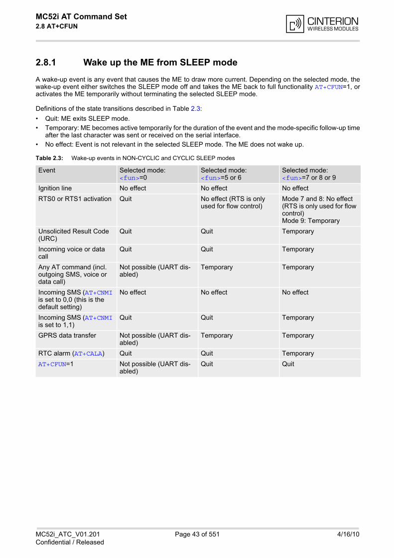
MC52i AT Command Set 2.8 AT+CFUN
MC52i_ATC_V01.201 Page 43 of 551 4/16/10Confidential / Released
2.8.1 Wake up the ME from SLEEP mode
A wake-up event is any event that causes the ME to draw more current. Depending on the selected mode, thewake-up event either switches the SLEEP mode off and takes the ME back to full functionality AT+CFUN=1, oractivates the ME temporarily without terminating the selected SLEEP mode.
Definitions of the state transitions described in Table 2.3:
• Quit: ME exits SLEEP mode.
• Temporary: ME becomes active temporarily for the duration of the event and the mode-specific follow-up timeafter the last character was sent or received on the serial interface.
• No effect: Event is not relevant in the selected SLEEP mode. The ME does not wake up.
Table 2.3: Wake-up events in NON-CYCLIC and CYCLIC SLEEP modes
Event Selected mode:<fun>=0
Selected mode:<fun>=5 or 6
Selected mode:<fun>=7 or 8 or 9
Ignition line No effect No effect No effect
RTS0 or RTS1 activation Quit No effect (RTS is only used for flow control)
Mode 7 and 8: No effect (RTS is only used for flow control)Mode 9: Temporary
Unsolicited Result Code (URC)
Quit Quit Temporary
Incoming voice or data call
Quit Quit Temporary
Any AT command (incl. outgoing SMS, voice or data call)
Not possible (UART dis-abled)
Temporary Temporary
Incoming SMS (AT+CNMI is set to 0,0 (this is the default setting)
No effect No effect No effect
Incoming SMS (AT+CNMI is set to 1,1)
Quit Quit Temporary
GPRS data transfer Not possible (UART dis-abled)
Temporary Temporary
RTC alarm (AT+CALA) Quit Quit Temporary
AT+CFUN=1 Not possible (UART dis-abled)
Quit Quit
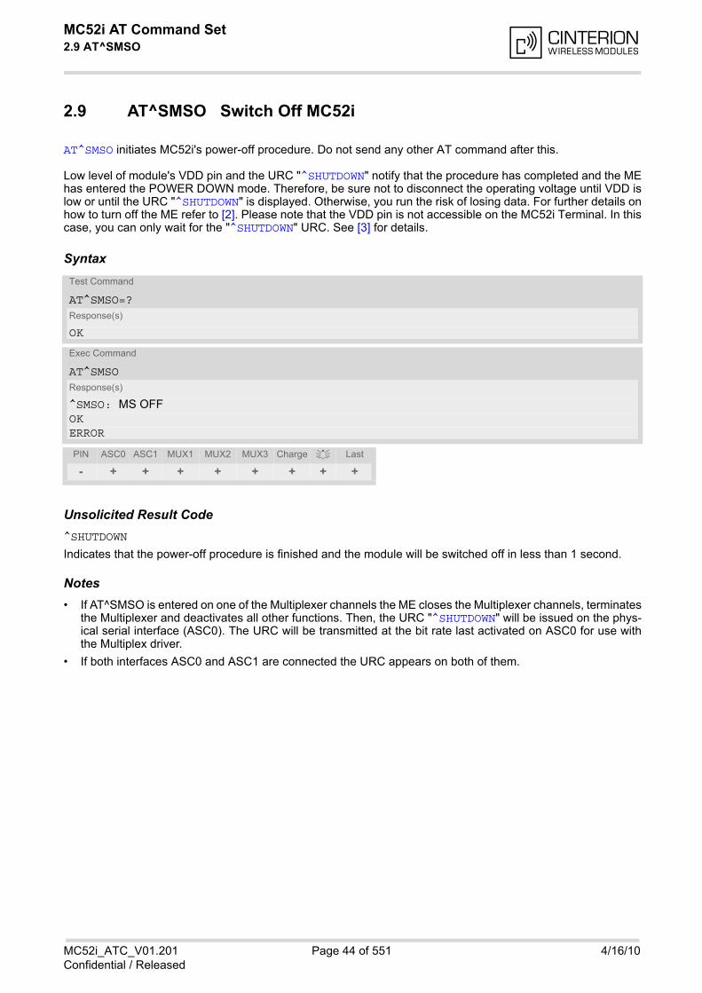
MC52i AT Command Set 2.9 AT^SMSO
MC52i_ATC_V01.201 Page 44 of 551 4/16/10Confidential / Released
2.9 AT^SMSO Switch Off MC52i
AT^SMSO initiates MC52i's power-off procedure. Do not send any other AT command after this.
Low level of module's VDD pin and the URC "^SHUTDOWN" notify that the procedure has completed and the MEhas entered the POWER DOWN mode. Therefore, be sure not to disconnect the operating voltage until VDD islow or until the URC "^SHUTDOWN" is displayed. Otherwise, you run the risk of losing data. For further details onhow to turn off the ME refer to [2]. Please note that the VDD pin is not accessible on the MC52i Terminal. In thiscase, you can only wait for the "^SHUTDOWN" URC. See [3] for details.
Syntax
Unsolicited Result Code^SHUTDOWN
Indicates that the power-off procedure is finished and the module will be switched off in less than 1 second.
Notes• If AT^SMSO is entered on one of the Multiplexer channels the ME closes the Multiplexer channels, terminates
the Multiplexer and deactivates all other functions. Then, the URC "^SHUTDOWN" will be issued on the phys-ical serial interface (ASC0). The URC will be transmitted at the bit rate last activated on ASC0 for use withthe Multiplex driver.
• If both interfaces ASC0 and ASC1 are connected the URC appears on both of them.
Test Command
AT^SMSO=?Response(s)
OK
Exec Command
AT^SMSOResponse(s)
^SMSO: MS OFFOKERROR
PIN ASC0 ASC1 MUX1 MUX2 MUX3 Charge Last
- + + + + + + + +
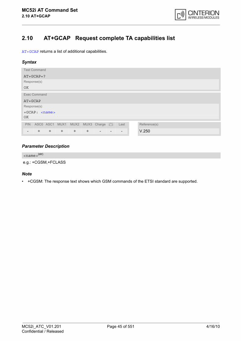
MC52i AT Command Set 2.10 AT+GCAP
MC52i_ATC_V01.201 Page 45 of 551 4/16/10Confidential / Released
2.10 AT+GCAP Request complete TA capabilities list
AT+GCAP returns a list of additional capabilities.
Syntax
Parameter Description
e.g.: +CGSM,+FCLASS
Note• +CGSM: The response text shows which GSM commands of the ETSI standard are supported.
Test Command
AT+GCAP=?Response(s)
OK
Exec Command
AT+GCAPResponse(s)
+GCAP: <name>OK
PIN ASC0 ASC1 MUX1 MUX2 MUX3 Charge Last Reference(s)
- + + + + + - - - V.250
<name>(str)
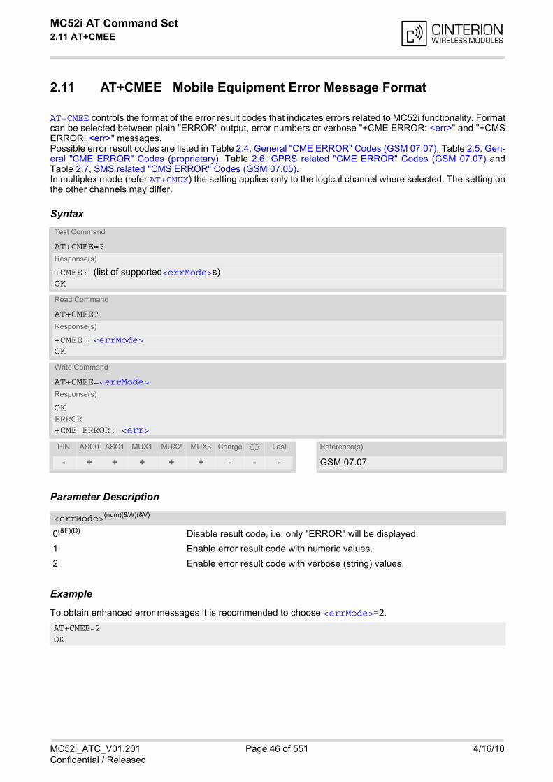
MC52i AT Command Set 2.11 AT+CMEE
MC52i_ATC_V01.201 Page 46 of 551 4/16/10Confidential / Released
2.11 AT+CMEE Mobile Equipment Error Message Format
AT+CMEE controls the format of the error result codes that indicates errors related to MC52i functionality. Formatcan be selected between plain "ERROR" output, error numbers or verbose "+CME ERROR: <err>" and "+CMSERROR: <err>" messages. Possible error result codes are listed in Table 2.4, General "CME ERROR" Codes (GSM 07.07), Table 2.5, Gen-eral "CME ERROR" Codes (proprietary), Table 2.6, GPRS related "CME ERROR" Codes (GSM 07.07) andTable 2.7, SMS related "CMS ERROR" Codes (GSM 07.05). In multiplex mode (refer AT+CMUX) the setting applies only to the logical channel where selected. The setting onthe other channels may differ.
Syntax
Parameter Description
0(&F)(D) Disable result code, i.e. only "ERROR" will be displayed.
1 Enable error result code with numeric values.
2 Enable error result code with verbose (string) values.
Example
To obtain enhanced error messages it is recommended to choose <errMode>=2.
Test Command
AT+CMEE=?Response(s)
+CMEE: (list of supported<errMode>s)OK
Read Command
AT+CMEE?Response(s)
+CMEE: <errMode>OK
Write Command
AT+CMEE=<errMode>Response(s)
OK ERROR +CME ERROR: <err>
PIN ASC0 ASC1 MUX1 MUX2 MUX3 Charge Last Reference(s)
- + + + + + - - - GSM 07.07
<errMode>(num)(&W)(&V)
AT+CMEE=2OK
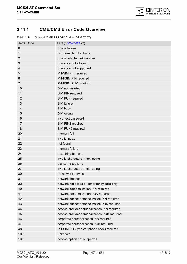
MC52i AT Command Set 2.11 AT+CMEE
MC52i_ATC_V01.201 Page 47 of 551 4/16/10Confidential / Released
2.11.1 CME/CMS Error Code Overview
Table 2.4: General "CME ERROR" Codes (GSM 07.07)
<err> Code Text (if AT+CMEE=2)
0 phone failure
1 no connection to phone
2 phone adapter link reserved
3 operation not allowed
4 operation not supported
5 PH-SIM PIN required
6 PH-FSIM PIN required
7 PH-FSIM PUK required
10 SIM not inserted
11 SIM PIN required
12 SIM PUK required
13 SIM failure
14 SIM busy
15 SIM wrong
16 incorrect password
17 SIM PIN2 required
18 SIM PUK2 required
20 memory full
21 invalid index
22 not found
23 memory failure
24 text string too long
25 invalid characters in text string
26 dial string too long
27 invalid characters in dial string
30 no network service
31 network timeout
32 network not allowed - emergency calls only
40 network personalization PIN required
41 network personalization PUK required
42 network subset personalization PIN required
43 network subset personalization PUK required
44 service provider personalization PIN required
45 service provider personalization PUK required
46 corporate personalization PIN required
47 corporate personalization PUK required
48 PH-SIM PUK (master phone code) required
100 unknown
132 service option not supported
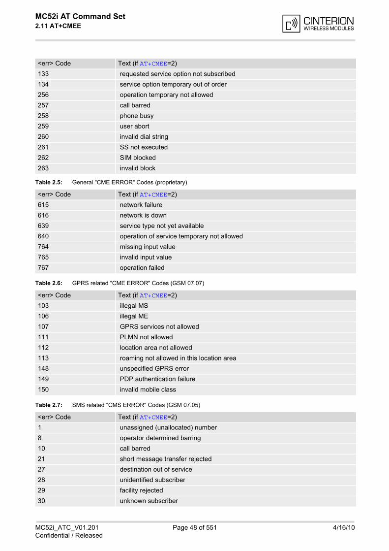
MC52i AT Command Set 2.11 AT+CMEE
MC52i_ATC_V01.201 Page 48 of 551 4/16/10Confidential / Released
Table 2.5: General "CME ERROR" Codes (proprietary)
Table 2.6: GPRS related "CME ERROR" Codes (GSM 07.07)
Table 2.7: SMS related "CMS ERROR" Codes (GSM 07.05)
133 requested service option not subscribed
134 service option temporary out of order
256 operation temporary not allowed
257 call barred
258 phone busy
259 user abort
260 invalid dial string
261 SS not executed
262 SIM blocked
263 invalid block
<err> Code Text (if AT+CMEE=2)
615 network failure
616 network is down
639 service type not yet available
640 operation of service temporary not allowed
764 missing input value
765 invalid input value
767 operation failed
<err> Code Text (if AT+CMEE=2)
103 illegal MS
106 illegal ME
107 GPRS services not allowed
111 PLMN not allowed
112 location area not allowed
113 roaming not allowed in this location area
148 unspecified GPRS error
149 PDP authentication failure
150 invalid mobile class
<err> Code Text (if AT+CMEE=2)
1 unassigned (unallocated) number
8 operator determined barring
10 call barred
21 short message transfer rejected
27 destination out of service
28 unidentified subscriber
29 facility rejected
30 unknown subscriber
<err> Code Text (if AT+CMEE=2)
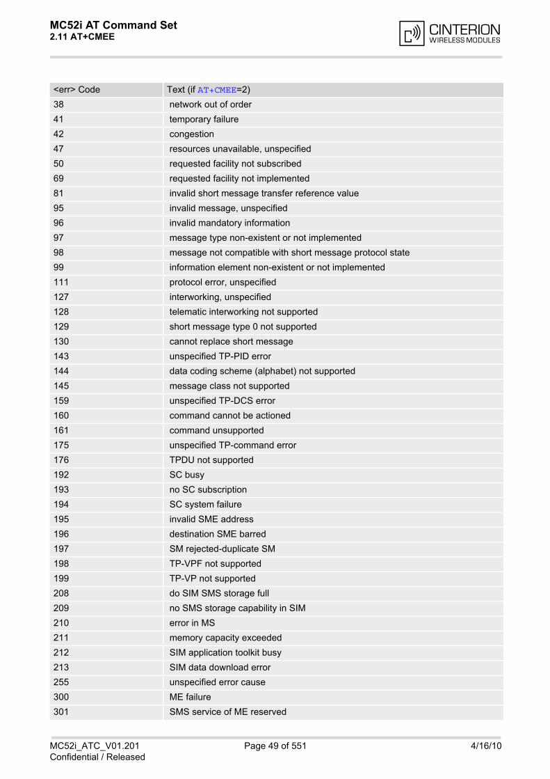
MC52i AT Command Set 2.11 AT+CMEE
MC52i_ATC_V01.201 Page 49 of 551 4/16/10Confidential / Released
38 network out of order
41 temporary failure
42 congestion
47 resources unavailable, unspecified
50 requested facility not subscribed
69 requested facility not implemented
81 invalid short message transfer reference value
95 invalid message, unspecified
96 invalid mandatory information
97 message type non-existent or not implemented
98 message not compatible with short message protocol state
99 information element non-existent or not implemented
111 protocol error, unspecified
127 interworking, unspecified
128 telematic interworking not supported
129 short message type 0 not supported
130 cannot replace short message
143 unspecified TP-PID error
144 data coding scheme (alphabet) not supported
145 message class not supported
159 unspecified TP-DCS error
160 command cannot be actioned
161 command unsupported
175 unspecified TP-command error
176 TPDU not supported
192 SC busy
193 no SC subscription
194 SC system failure
195 invalid SME address
196 destination SME barred
197 SM rejected-duplicate SM
198 TP-VPF not supported
199 TP-VP not supported
208 do SIM SMS storage full
209 no SMS storage capability in SIM
210 error in MS
211 memory capacity exceeded
212 SIM application toolkit busy
213 SIM data download error
255 unspecified error cause
300 ME failure
301 SMS service of ME reserved
<err> Code Text (if AT+CMEE=2)

MC52i AT Command Set 2.11 AT+CMEE
MC52i_ATC_V01.201 Page 50 of 551 4/16/10Confidential / Released
302 operation not allowed
303 operation not supported
304 invalid PDU mode parameter
305 invalid text mode parameter
310 SIM not inserted
311 SIM PIN required
312 PH-SIM PIN required
313 SIM failure
314 SIM busy
315 SIM wrong
316 SIM PUK required
317 SIM PIN2 required
318 SIM PUK2 required
320 memory failure
321 invalid memory index
322 memory full
330 SMSC address unknown
331 no network service
332 network timeout
340 no +CNMA acknowledgement expected
500 unknown error
512 user abort
513 unable to store
514 invalid status
515 invalid character in address string
516 invalid length
517 invalid character in PDU
518 invalid parameter
519 invalid length or character
520 invalid character in text
521 timer expired
522 operation temporary not allowed
<err> Code Text (if AT+CMEE=2)
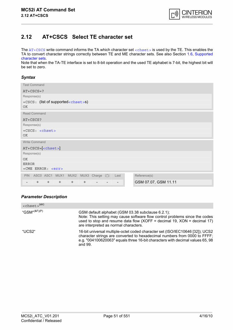
MC52i AT Command Set 2.12 AT+CSCS
MC52i_ATC_V01.201 Page 51 of 551 4/16/10Confidential / Released
2.12 AT+CSCS Select TE character set
The AT+CSCS write command informs the TA which character set <chset> is used by the TE. This enables theTA to convert character strings correctly between TE and ME character sets. See also Section 1.6, Supportedcharacter sets.Note that when the TA-TE interface is set to 8-bit operation and the used TE alphabet is 7-bit, the highest bit willbe set to zero.
Syntax
Parameter Description
“GSM“(&F)(P) GSM default alphabet (GSM 03.38 subclause 6.2.1);Note: This setting may cause software flow control problems since the codesused to stop and resume data flow (XOFF = decimal 19, XON = decimal 17)are interpreted as normal characters.
“UCS2“ 16-bit universal multiple-octet coded character set (ISO/IEC10646 [32]); UCS2character strings are converted to hexadecimal numbers from 0000 to FFFF;e.g. "004100620063" equals three 16-bit characters with decimal values 65, 98and 99.
Test Command
AT+CSCS=?Response(s)
+CSCS: (list of supported<chset>s)OK
Read Command
AT+CSCS?Response(s)
+CSCS: <chset>OK
Write Command
AT+CSCS=[<chset>]Response(s)
OKERROR+CME ERROR: <err>
PIN ASC0 ASC1 MUX1 MUX2 MUX3 Charge Last Reference(s)
- + + + + + - - - GSM 07.07, GSM 11.11
<chset>(str)

MC52i AT Command Set 2.13 AT^SCFG
MC52i_ATC_V01.201 Page 52 of 551 4/16/10Confidential / Released
2.13 AT^SCFG Extended Configuration Settings
AT^SCFG can be used to query and configure various settings of the MC52i. AT^SCFG read command returns a list of all supported parameters and their current values. AT^SCFG write command queries a configuration parameter (if no value is entered) or sets its value(s). Input of parameter names is always coded in GSM character set, parameter values are expected to be given asspecified via AT+CSCS.
SyntaxTest Command
AT^SCFG=?Response(s)
^SCFG: "Audio/AMR", (list of supported <amr>s) ^SCFG: "Audio/Loop", (list of supported <al>s)^SCFG: "Call/SpeechVersion1", (list of supported <csv1>s)^SCFG: "GPRS/ATS0/withAttach", (list of supported <gs0aa>s)^SCFG: "GPRS/RingOnIncomingData", (list of supported <groid>s)^SCFG: "PowerSaver/Mode9/Timeout", (list of supported <psm9to>s)^SCFG: "Radio/Band/HandOver", (list of supported <HandOverStatus>s)^SCFG: "Tcp/IRT", (list of supported <tcpIrt>)^SCFG: "Tcp/MR", (list of supported <tcpMr>)^SCFG: "Tcp/OT", (list of supported <tcpOt>)^SCFG: "Tcp/WithURCs", (list of supported <tcpWithUrc>)^SCFG: "URC/CallStatus/CIEV", (list of supported <succ>s)^SCFG: "URC/CallStatus/SLCC", (list of supported <sucs>s)^SCFG: "URC/Datamode/Ringline", (list of supported <udri>s) ^SCFG: "URC/Ringline", (list of supported <uri>s)^SCFG: "URC/Ringline/ActiveTime", (list of supported <urat>s)OK
Read Command
AT^SCFG?Response(s)
^SCFG: "Audio/AMR", <amr>1[, <amr>2[, <amr>3...[<amr>10]]]^SCFG: "Audio/Loop", <al>^SCFG: "Call/SpeechVersion1", <csv1>^SCFG: "GPRS/ATS0/withAttach", <gs0aa>^SCFG: "GPRS/RingOnIncomingData", <groid>^SCFG: "PowerSaver/Mode9/Timeout", <psm9to>^SCFG: "Radio/Band/HandOver", <HandOverStatus>^SCFG: "Tcp/IRT", <tcpIrt>^SCFG: "Tcp/MR", <tcpMr>^SCFG: "Tcp/OT", <tcpOt>^SCFG: "Tcp/WithURCs", <tcpWithUrc>^SCFG: "URC/CallStatus/CIEV", <succ>^SCFG: "URC/CallStatus/SLCC", <sucs>^SCFG: "URC/Datamode/Ringline", <udri>^SCFG: "URC/Ringline", <uri>^SCFG: "URC/Ringline/ActiveTime", <urat>OK
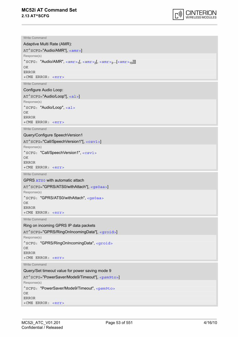
MC52i AT Command Set 2.13 AT^SCFG
MC52i_ATC_V01.201 Page 53 of 551 4/16/10Confidential / Released
Write Command
Adaptive Multi Rate (AMR):
AT^SCFG="Audio/AMR"[, <amr>]Response(s)
^SCFG: "Audio/AMR", <amr>1[, <amr>2[, <amr>3...[<amr>10]]]OKERROR+CME ERROR: <err>
Write Command
Configure Audio Loop:
AT^SCFG="Audio/Loop"[, <al>]Response(s)
^SCFG: "Audio/Loop", <al>OKERROR+CME ERROR: <err>
Write Command
Query/Configure SpeechVersion1
AT^SCFG="Call/SpeechVersion1"[, <csv1>]Response(s)
^SCFG: "Call/SpeechVersion1", <csv1>OKERROR+CME ERROR: <err>
Write Command
GPRS ATS0 with automatic attach
AT^SCFG="GPRS/ATS0/withAttach"[, <gs0aa>]Response(s)
^SCFG: "GPRS/ATS0/withAttach", <gs0aa>OKERROR+CME ERROR: <err>
Write Command
Ring on incoming GPRS IP data packets
AT^SCFG="GPRS/RingOnIncomingData"[, <groid>]Response(s)
^SCFG: "GPRS/RingOnIncomingData", <groid>OKERROR+CME ERROR: <err>
Write Command
Query/Set timeout value for power saving mode 9
AT^SCFG="PowerSaver/Mode9/Timeout"[, <psm9to>]Response(s)
^SCFG: "PowerSaver/Mode9/Timeout", <psm9to>OKERROR+CME ERROR: <err>
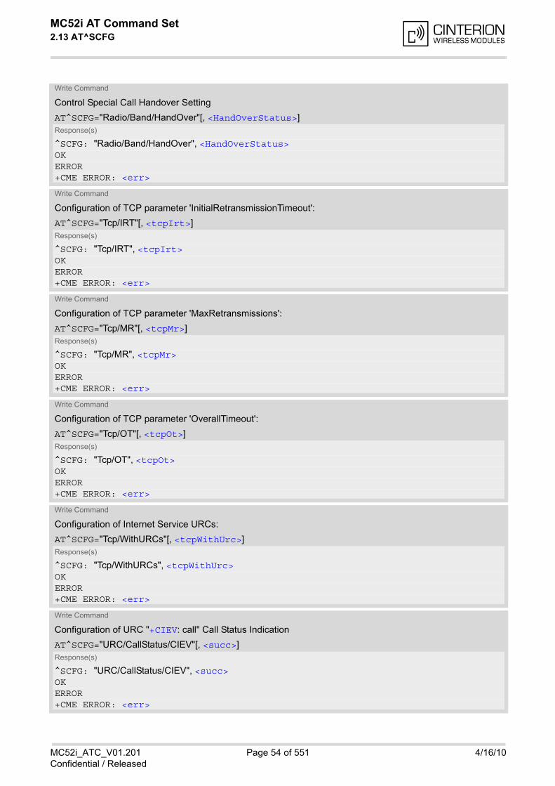
MC52i AT Command Set 2.13 AT^SCFG
MC52i_ATC_V01.201 Page 54 of 551 4/16/10Confidential / Released
Write Command
Control Special Call Handover Setting
AT^SCFG="Radio/Band/HandOver"[, <HandOverStatus>]Response(s)
^SCFG: "Radio/Band/HandOver", <HandOverStatus>OKERROR+CME ERROR: <err>
Write Command
Configuration of TCP parameter 'InitialRetransmissionTimeout':
AT^SCFG="Tcp/IRT"[, <tcpIrt>]Response(s)
^SCFG: "Tcp/IRT", <tcpIrt>OKERROR+CME ERROR: <err>
Write Command
Configuration of TCP parameter 'MaxRetransmissions':
AT^SCFG="Tcp/MR"[, <tcpMr>]Response(s)
^SCFG: "Tcp/MR", <tcpMr>OKERROR+CME ERROR: <err>
Write Command
Configuration of TCP parameter 'OverallTimeout':
AT^SCFG="Tcp/OT"[, <tcpOt>]Response(s)
^SCFG: "Tcp/OT", <tcpOt>OKERROR+CME ERROR: <err>
Write Command
Configuration of Internet Service URCs:
AT^SCFG="Tcp/WithURCs"[, <tcpWithUrc>]Response(s)
^SCFG: "Tcp/WithURCs", <tcpWithUrc>OKERROR+CME ERROR: <err>
Write Command
Configuration of URC "+CIEV: call" Call Status Indication
AT^SCFG="URC/CallStatus/CIEV"[, <succ>]Response(s)
^SCFG: "URC/CallStatus/CIEV", <succ>OKERROR+CME ERROR: <err>
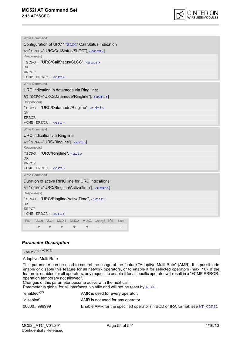
MC52i AT Command Set 2.13 AT^SCFG
MC52i_ATC_V01.201 Page 55 of 551 4/16/10Confidential / Released
Parameter Description
Adaptive Multi Rate
This parameter can be used to control the usage of the feature "Adaptive Multi Rate" (AMR). It is possible toenable or disable this feature for all network operators, or to enable it for selected operators (max. 10). If thefeature is enabled for all operators, any request to enable it for a specific operator will result in a "+CME ERROR:operation temporary not allowed". Changes of this parameter become active with the next call. Parameter is global for all interfaces, volatile and will not be reset by AT&F.
“enabled“(P) AMR is used for every operator.
“disabled“ AMR is not used for any operator.
00000...999999 Enable AMR for the specified operator (in BCD or IRA format; see AT+COPS).
Write Command
Configuration of URC "^SLCC" Call Status Indication
AT^SCFG="URC/CallStatus/SLCC"[, <sucs>]Response(s)
^SCFG: "URC/CallStatus/SLCC", <sucs>OKERROR+CME ERROR: <err>
Write Command
URC indication in datamode via Ring line:
AT^SCFG="URC/Datamode/Ringline"[, <udri>]Response(s)
^SCFG: "URC/Datamode/Ringline", <udri>OKERROR+CME ERROR: <err>
Write Command
URC indication via Ring line:
AT^SCFG="URC/Ringline"[, <uri>]Response(s)
^SCFG: "URC/Ringline", <uri>OKERROR+CME ERROR: <err>
Write Command
Duration of active RING line for URC indications:
AT^SCFG="URC/Ringline/ActiveTime"[, <urat>]Response(s)
^SCFG: "URC/Ringline/ActiveTime", <urat>OKERROR+CME ERROR: <err>
PIN ASC0 ASC1 MUX1 MUX2 MUX3 Charge Last
- + + + + + - - -
<amr>(str)(+CSCS)
MC52i AT Command Set 2.13 AT^SCFG
MC52i_ATC_V01.201 Page 56 of 551 4/16/10Confidential / Released
Audio Loop Setting
This parameter can be used to configure an audio loop for performing a simple verification of audio connections.The feature is intended for testing only. Full audio processing will be performed. Audio parameterization capabilities remain nearly unrestricted. Micro-phone and loudspeaker ports can be selected with random access. The audio loop cannot be used in combina-tion with the digital audio interface. Neither a SIM-card nor a GSM network is necessary to turn the audio loop on. Turning the audio loop on activates audio mode 0 which cannot be selected during normal operation of the mod-ule. Turning the audio loop off activates audio mode 1. The active audio mode can be verified via AT^SNFS. Audio mode 0 contains linear filters and neither echo canceller nor noise suppression are activated. It is alsopossible to select any other audio mode. These audio modes use the parameterization set as default during nor-mal operation of the module. Activation of the audio loop turns sidetone off, even if sidetone is on in the selected audio mode during normaloperation. Audio path can be selected via AT command AT^SAIC. Audio mode can be selected via AT commandAT^SNFS. Parameter is global for all interfaces, volatile and will not be reset by AT&F.
“0“(P) No audio loop active
“1“ Audio loop active
Call Speech Version1
This parameter can be used to query or configure the speech version 1 indication in the bearer capabilities incase of voice calls (see GSM 04.08). Speech version 2 (EFR) is always enabled; speech version 3 ( AMR) isnot affected by this command. If you try to change this parameter as long as a circuit switched call is active, the command returns the new valueand "OK", but the changes will not take effect before next call setup.Parameter is global for the ME, volatile and will not be reset by AT&F.
“0“(P) FR and HR codecs are enabled for speech calls - full rate codec is preferred.
“1“ FR and HR codecs are enabled for speech calls - half rate codec is preferred.
“2“ Half rate codec is disabled for speech calls.
GPRS ATS0 with Attach
This parameter can be used to control the behaviour of ATS0.Parameter is global for all interfaces, volatile and will not be reset by AT&F.
“on“(P) When the ATS0=<n> (<n>>0) command is received, the MT will attempt to per-form a GPRS attach.
“off“ When the ATS0=<n> (<n>>0) command is received, the MT will not attempt toperform a GPRS attach.
<al>(str)
<csv1>(str)(+CSCS)
<gs0aa>(str)(+CSCS)
MC52i AT Command Set 2.13 AT^SCFG
MC52i_ATC_V01.201 Page 57 of 551 4/16/10Confidential / Released
Ring on incoming GPRS IP data packets
This parameter can be used to control the behaviour of the RING line for incoming IP packets in GPRS onlinemode.Parameter is local for the interface, volatile and will not be reset by AT&F.
“on“ If the ME is in power saving mode 7 or 8 or 9 (see AT+CFUN) and hardwareflow control is in use (AT\Q3) and the RTS line is inactive and there are incom-ing IP packets for a GPRS context which is online, then the RING line will beactivated once, for a time which is configured by the parameter "URC/Ringline/ActiveTime" (<urat>). The RING line to be used can be configured with theparameter "URC/Ringline" (<uri>).
“off“(P) RING line is not activated for incoming IP packets.
Power saving mode 9 timeout
This parameter can be used to query or configure the wake up time for power saving mode 9 (see AT+CFUN withparameter <fun>=9). Parameter is global for the ME, volatile and will not be reset by AT&F.
5...20(P)...36000 The granularity of the timeout value is 100ms (i.e. a value of 10 equal 1 sec-ond). The minimum timeout value that can be applied is 5, but accuracy is onlyguaranteed for timeout values greater than 20.
Call Handover Status
This parameter offers a workaround to prevent problems during call handover into the 1900 MHz band, causedby non-conforming configurations of the 1900 MHz GSM network.
“0“(P) Disable workaround.
“1“ Enable workaround. This value should be selected when handover into a 1900MHz GSM network fails. If required for permanent use the value needs to beset each time the ME is restarted.
Initial Retransmission Timeout (IRT)
1...3(&F)(D)...60 This parameter determines the time (in seconds) the TCP/IP stack will waitbefore starting the first retransmission of packets during the initial connectionestablishment phase. The TCP protocol ensures the retransmission of packets several times atincreasing intervals until some upper limit is reached. This mechanism prevents packet loss and serious congestion problems. Inaddition, the parameters <tcpMr> and <tcpOt> can be set to further optimizethis mechanism for special conditions depending on the mobile network. Parameter is global for the ME and non-volatile. Use of default value is recom-mended. If changed the new value takes effect the next time you start an Inter-net service with AT^SISO.
Maximum Number of Retransmissions (MR)
1...10(&F)(D)...30 This parameter determines the maximum number of times to retransmit TCPpackets. The value set with <tcpMr> will be assumed as default for the <srv-ParmTag> "tcpMR" when a new service profile is created with AT^SISS. Ineach service profile, you can set another "tcpMR" value which has precedence
<groid>(str)(+CSCS)
<psm9to>(str)(+CSCS)
<HandOverStatus>(str)(+CSCS)
<tcpIrt>(str)(+CSCS)
<tcpMr>(str)(+CSCS)

MC52i AT Command Set 2.13 AT^SCFG
MC52i_ATC_V01.201 Page 58 of 551 4/16/10Confidential / Released
over the global value set with AT^SCFG. Existing service profiles are notaffected when you change the global value via AT^SCFG. Parameter is global for the ME and non-volatile. Use of default value is recom-mended.
Overall TCP Timer for outstanding connections (tcpOT)
1...6000(&F)(D) This parameter specifies the number of seconds to wait before closing a con-nection if TCP/IP packets are not acknowledged. Setting the maximum value is practically equivalent to deactivating the tcpOTmechanism because the maximum time would never be reached by the TCP/IP stack. The value set with <tcpOt> will be assumed as default for the <srv-ParmTag> "tcpOT" when a new service profile is created with AT^SISS. How-ever, in each service profile, you can set another "tcpOT" value which hasprecedence over the global value set with AT^SCFG. Existing service profilesare not affected when you change the global value via AT^SCFG. Parameter is non-volatile. Use of default value is recommended.
URC mode or polling mode for Internet service commands
This parameter enables or disables the presentation of the following URCs related to Internet service com-mands: "^SISR" URC, "^SISW" URC and "^SIS" URC for parameter <urcCause>=0 (Internet service events)."^SIS" URCs with <urcCause>=1 or 2 used to indicate incoming Socket connections are always enabled. Parameter is global for the ME and non-volatile.
“on“(&F)(D) Enable URCs related to Internet service commands.Throughout the Chapter "Internet Service AT Commands" the mode is alsoreferred to as URC mode.
“off“ Disable URCs related to Internet service commands. This requires the host application to employ polling techniques when using theInternet service AT commands: The host application is responsible to retrieveall status information needed to control an Internet session. The method isreferred to as polling mode.
CIEV Call Status Indication
This parameter can be used to control the behaviour of URC "+CIEV: call". See also AT+CIND, AT+CMER andSection 7.1, Call Status Information.Parameter is global for all interfaces and will not be reset by AT&F.
“restricted“(P) URC "+CIEV: call" will be issued only when a Call Status transition ends instate "active" or "unknown" (see Section 7.1, Call Status Information) for a callin the list of active calls.
“verbose“ URC "+CIEV: call" will be issued when any state transition (including transi-tions beginning or ending in state "unknown") occurs in the list of active calls,or when a traffic channel is established.
<tcpOt>(str)(+CSCS)
<tcpWithUrc>(str)(+CSCS)
<succ>(str)(+CSCS)
MC52i AT Command Set 2.13 AT^SCFG
MC52i_ATC_V01.201 Page 59 of 551 4/16/10Confidential / Released
SLCC Call Status Indication
This parameter can be used to control the behaviour of URC "^SLCC". See also AT^SLCC and Section 7.1, CallStatus Information.Parameter is global for all interfaces and will not be reset by AT&F.
“restricted“ URC "^SLCC" will be issued only when a Call Status transition ends in state"active" or "unknown" (see Section 7.1, Call Status Information) for a call in thelist of active calls
“verbose“(P) URC "^SLCC" will be issued when any state transition (including transitionsbeginning or ending in state "unknown") occurs in the list of active calls, orwhen a traffic channel is established.
URC RING line
This parameter can be used to control the behaviour of the RING line to indicate URCs (both for idle interfacesand, if configured by the parameter "URC/Datamode/Ringline", if link is reserved) and, if configured, the indicatorfor incoming IP packets (see parameter "GPRS/RingOnIncomingData" (<groid>).Parameter is local for the interface, volatile and will not be reset by AT&F.
“off“ URC is not indicated by RING.
“local“(P) URC will be indicated by an activated RING line of the interface on which theURC appears
“asc0“ URC is indicated by an activated RING0 line.
URC Datamode RING line
This parameter specifies whether RING or BREAK is used for the signaling of URCs when the TA-TE link isreserved (e.g. during circuit-switched data calls, fax connections, in GPRS data mode, in transparent TCPaccess mode opened with AT^SIST or during the execution of an AT command).Parameter is global for all interfaces, volatile and will not be reset by AT&F.
“off“(P) URC will be indicated by BREAK
“on“ URC is indicated by an active RING line for a time which is configured by theparameter "URC/Ringline/ActiveTime" (<urat>). The RING line which will beused, can be configured by the parameter "URC/Ringline" (<uri>).
URC RING line Active Time
This parameter can be used to control how long the RING line is activated to indicate URCs (both for idle inter-faces and, if configured by the parameter "URC/Datamode/Ringline" (<udri>), if link is reserved) and, if con-figured by the parameter "GPRS/RingOnIncomingData", to indicate incoming GPRS IP data packets(<groid>).Parameter is global for all interfaces, volatile and will not be reset by AT&F.
“0“ RING line will be activated for a time between 4.6 and 9.2 ms.
“1“ RING line will be activated for about 100ms.
“2“(P) RING line will be activated for about 1s.
Note• Parameters "GPRS/ATS0/withAttach" (<gs0aa>) and "GPRS/RingOnIncomingData" (<groid>) are avail-
able only for modules supporting GPRS.
<sucs>(str)(+CSCS)
<uri>(str)(+CSCS)
<udri>(str)(+CSCS)
<urat>(str)(+CSCS)

MC52i AT Command Set 2.13 AT^SCFG
MC52i_ATC_V01.201 Page 60 of 551 4/16/10Confidential / Released
ExamplesEXAMPLE 1
Usage of "Audio/AMR":
EXAMPLE 2
Usage of "URC/Ringline" and "URC/Datamode/Ringline":
AT+CSCS="UCS2" Switch to UCS2 character set.OKAT^SCFG? Query all parameters....^SCFG:"Audio/AMR","0065006E00610062006C00650064"...OKAT+CSCS="GSM"OKAT^SCFG?...^SCFG:"Audio/AMR","enabled" AMR will be used for any operator....OKAT^SCFG="Audio/AMR","disabled"^SCFG:"Audio/AMR","disabled" AMR is disabled for any operator.OKAT^SCFG="Audio/AMR","23405"^SCFG:"Audio/AMR","23405" AMR is disabled for any operator, but enabled for
operator "23405".OKAT^SCFG="Audio/AMR","23203"^SCFG:"Audio/AMR","23405","23203" AMR is disabled for any operator, but enabled for
operators "23405" and "23203".OKAT^SCFG="Audio/AMR" Query parameter "Audio/AMR"^SCFG:"Audio/AMR","23405","23203"OK
AT+CSCS="GSM" Switch to GSM character set.OKAT^SCFG? Query all parameters....^SCFG:"URC/Datamode/Ringline","off" While the TA-TE link is reserved URCs will be indi-
cated by BREAK.^SCFG:"URC/Ringline","local" URCs on this interface will be indicated by Ring line
associated to the interface (e.g. RING0 for ASC0)....OKAT^SCFG="URC/Datamode/Ringline","on"^SCFG:"URC/Datamode/Ringline","on" While the TA-TE link is reserved URCs will be indi-
cated by an activated "local" Ring line.OKAT^SCFG="URC/Ringline","asc0"^SCFG:"URC/Ringline","asc0" URCs on this interface will be indicated by an acti-
vated RING0 no matter whether or not the TA-TE linkis reserved.
OKAT^SCFG="URC/Datamode/Ringline","off"^SCFG:"URC/Datamode/Ringline","off" URCs on this interface will be indicated by an acti-
vated RING0 if the TA-TE link is not reserved and byBREAK if the TA-TE link is reserved.
MC52i AT Command Set 2.13 AT^SCFG
MC52i_ATC_V01.201 Page 61 of 551 4/16/10Confidential / Released
OKAT^SCFG="URC/Ringline" Disable any Ring line indication for URCs on this
interface.^SCFG:"URC/Ringline","off"OK
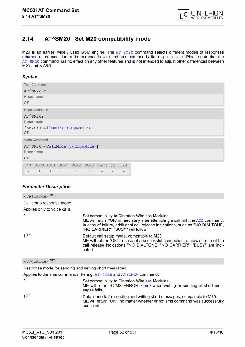
MC52i AT Command Set 2.14 AT^SM20
MC52i_ATC_V01.201 Page 62 of 551 4/16/10Confidential / Released
2.14 AT^SM20 Set M20 compatibility mode
M20 is an earlier, widely used GSM engine. The AT^SM20 command selects different modes of responsesreturned upon execution of the commands ATD and sms commands like e.g. AT+CMGW. Please note that theAT^SM20 command has no effect on any other features and is not intended to adjust other differences betweenM20 and MC52i.
Syntax
Parameter Description
Call setup response mode
Applies only to voice calls.
0 Set compatibility to Cinterion Wireless Modules.ME will return "OK" immediately after attempting a call with the ATD command.In case of failure, additional call release indications, such as "NO DIALTONE,"NO CARRIER", "BUSY" will follow.
1(&F) Default call setup mode, compatible to M20.ME will return "OK" in case of a successful connection, otherwise one of thecall release indications "NO DIALTONE, "NO CARRIER", "BUSY" are indi-cated.
Response mode for sending and writing short messages
Applies to the sms commands like e.g. AT+CMGS and AT+CMGW command.
0 Set compatibility to Cinterion Wireless Modules.ME will return +CMS ERROR: <err> when writing or sending of short mes-sages fails.
1(&F) Default mode for sending and writing short messages, compatible to M20.ME will return "OK", no matter whether or not sms command was successfullyexecuted.
Test Command
AT^SM20=?Response(s)
OK
Read Command
AT^SM20?Response(s)
^SM20:<CallMode>, <CmgwMode>OK
Write Command
AT^SM20=<CallMode>[, <CmgwMode>]Response(s)
OK
PIN ASC0 ASC1 MUX1 MUX2 MUX3 Charge Last
- + + + + + - - -
<CallMode>(num)
<CmgwMode>(num)
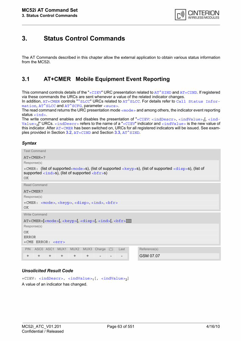
MC52i AT Command Set 3. Status Control Commands
MC52i_ATC_V01.201 Page 63 of 551 4/16/10Confidential / Released
3. Status Control Commands
The AT Commands described in this chapter allow the external application to obtain various status informationfrom the MC52i.
3.1 AT+CMER Mobile Equipment Event Reporting
This command controls details of the "+CIEV" URC presentation related to AT^SIND and AT+CIND. If registeredvia these commands the URCs are sent whenever a value of the related indicator changes. In addition, AT+CMER controls "^SLCC" URCs related to AT^SLCC. For details refer to Call Status Infor-mation, AT^SLCC and AT^SCFG, parameter <sucs>.The read command returns the URC presentation mode <mode> and among others, the indicator event reportingstatus <ind>.The write command enables and disables the presentation of "+CIEV: <indDescr>, <indValue>1[, <ind-Value>2]" URCs. <indDescr> refers to the name of a "+CIEV" indicator and <indValue> is the new value ofthis indicator. After AT+CMER has been switched on, URCs for all registered indicators will be issued. See exam-ples provided in Section 3.2, AT+CIND and Section 3.3, AT^SIND.
Syntax
Unsolicited Result Code+CIEV: <indDescr>, <indValue>1[, <indValue>2]
A value of an indicator has changed.
Test Command
AT+CMER=?Response(s)
+CMER: (list of supported<mode>s), (list of supported <keyp>s), (list of supported <disp>s), (list of supported <ind>s), (list of supported <bfr>s)OK
Read Command
AT+CMER?Response(s)
+CMER: <mode>, <keyp>, <disp>, <ind>, <bfr>OK
Write Command
AT+CMER=[<mode>[, <keyp>[, <disp>[, <ind>[, <bfr>]]]]]Response(s)
OKERROR+CME ERROR: <err>
PIN ASC0 ASC1 MUX1 MUX2 MUX3 Charge Last Reference(s)
+ + + + + + - - - GSM 07.07
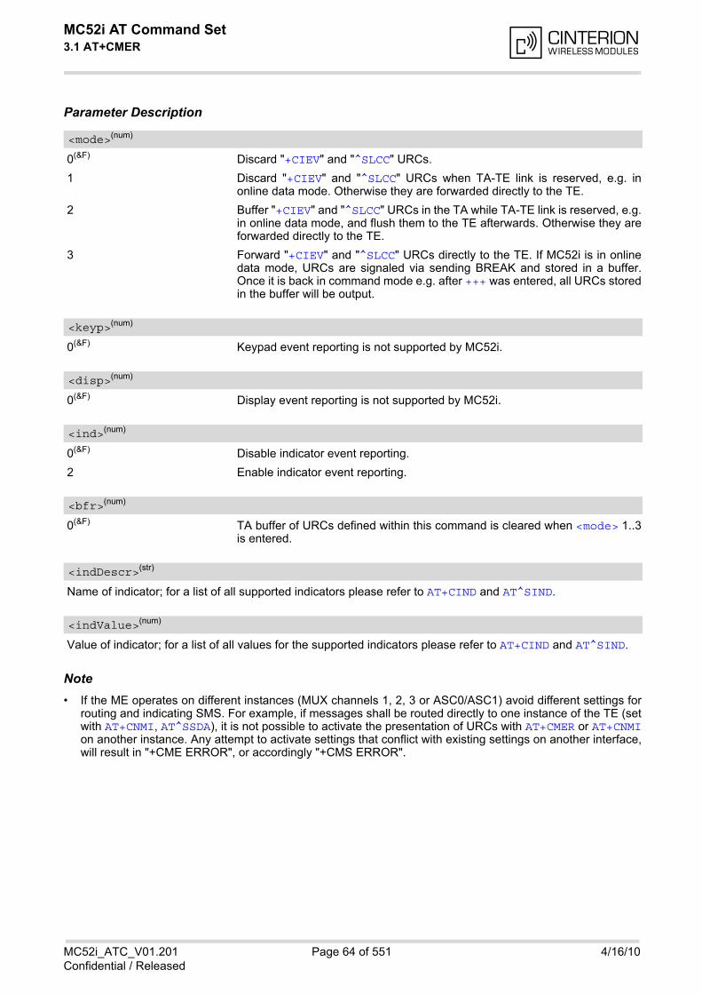
MC52i AT Command Set 3.1 AT+CMER
MC52i_ATC_V01.201 Page 64 of 551 4/16/10Confidential / Released
Parameter Description
0(&F) Discard "+CIEV" and "^SLCC" URCs.
1 Discard "+CIEV" and "^SLCC" URCs when TA-TE link is reserved, e.g. inonline data mode. Otherwise they are forwarded directly to the TE.
2 Buffer "+CIEV" and "^SLCC" URCs in the TA while TA-TE link is reserved, e.g.in online data mode, and flush them to the TE afterwards. Otherwise they areforwarded directly to the TE.
3 Forward "+CIEV" and "^SLCC" URCs directly to the TE. If MC52i is in onlinedata mode, URCs are signaled via sending BREAK and stored in a buffer.Once it is back in command mode e.g. after +++ was entered, all URCs storedin the buffer will be output.
0(&F) Keypad event reporting is not supported by MC52i.
0(&F) Display event reporting is not supported by MC52i.
0(&F) Disable indicator event reporting.
2 Enable indicator event reporting.
0(&F) TA buffer of URCs defined within this command is cleared when <mode> 1..3is entered.
Name of indicator; for a list of all supported indicators please refer to AT+CIND and AT^SIND.
Value of indicator; for a list of all values for the supported indicators please refer to AT+CIND and AT^SIND.
Note• If the ME operates on different instances (MUX channels 1, 2, 3 or ASC0/ASC1) avoid different settings for
routing and indicating SMS. For example, if messages shall be routed directly to one instance of the TE (setwith AT+CNMI, AT^SSDA), it is not possible to activate the presentation of URCs with AT+CMER or AT+CNMIon another instance. Any attempt to activate settings that conflict with existing settings on another interface,will result in "+CME ERROR", or accordingly "+CMS ERROR".
<mode>(num)
<keyp>(num)
<disp>(num)
<ind>(num)
<bfr>(num)
<indDescr>(str)
<indValue>(num)
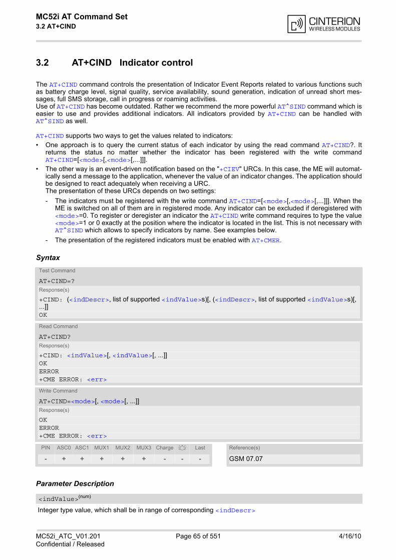
MC52i AT Command Set 3.2 AT+CIND
MC52i_ATC_V01.201 Page 65 of 551 4/16/10Confidential / Released
3.2 AT+CIND Indicator control
The AT+CIND command controls the presentation of Indicator Event Reports related to various functions suchas battery charge level, signal quality, service availability, sound generation, indication of unread short mes-sages, full SMS storage, call in progress or roaming activities. Use of AT+CIND has become outdated. Rather we recommend the more powerful AT^SIND command which iseasier to use and provides additional indicators. All indicators provided by AT+CIND can be handled withAT^SIND as well.
AT+CIND supports two ways to get the values related to indicators:
• One approach is to query the current status of each indicator by using the read command AT+CIND?. Itreturns the status no matter whether the indicator has been registered with the write commandAT+CIND=[<mode>[,<mode>[,...]]].
• The other way is an event-driven notification based on the "+CIEV" URCs. In this case, the ME will automat-ically send a message to the application, whenever the value of an indicator changes. The application shouldbe designed to react adequately when receiving a URC. The presentation of these URCs depends on two settings:
- The indicators must be registered with the write command AT+CIND=[<mode>[,<mode>[,...]]]. When theME is switched on all of them are in registered mode. Any indicator can be excluded if deregistered with<mode>=0. To register or deregister an indicator the AT+CIND write command requires to type the value<mode>=1 or 0 exactly at the position where the indicator is located in the list. This is not necessary withAT^SIND which allows to specify indicators by name. See examples below.
- The presentation of the registered indicators must be enabled with AT+CMER.
Syntax
Parameter Description
Integer type value, which shall be in range of corresponding <indDescr>
Test Command
AT+CIND=?Response(s)
+CIND: (<indDescr>, list of supported <indValue>s)[, (<indDescr>, list of supported <indValue>s)[, ...]]OK
Read Command
AT+CIND?Response(s)
+CIND: <indValue>[, <indValue>[, ...]]OKERROR+CME ERROR: <err>
Write Command
AT+CIND=<mode>[, <mode>[, ...]]Response(s)
OKERROR+CME ERROR: <err>
PIN ASC0 ASC1 MUX1 MUX2 MUX3 Charge Last Reference(s)
- + + + + + - - - GSM 07.07
<indValue>(num)

MC52i AT Command Set 3.2 AT+CIND
MC52i_ATC_V01.201 Page 66 of 551 4/16/10Confidential / Released
String values and their <indValue> ranges.More indications are available via AT^SIND. Therefore use of AT^SIND for control of all indications is recom-mended.The following indications are accessible via AT+CIND:
“battchg“ Battery charge level 0..4 or 5 if no measuring is performed, e.g because no bat-tery is connected. Also refer to AT^SBC.
“signal“ Signal quality (0..7) or (99) if not measurable The indicated value is the bit error rate of the signal received. Bit errors are esti-mated values. See also AT+CSQ.
“service“ Service availability (0-1)0: Not registered to any network1: Registered to home network or, if "roam"=1 then registered to another net-work
“sounder“ Sounder activity (0-1)Reports every event that causes the ME to generate a tone.Value 1 means for example:Incoming call - ME is ringing. Note that the URC "+CIEV: sounder" will be out-put only if ringing tones are activated with AT^SRTC.Waiting call - ME generates waiting call tone (if call waiting is enabled).Outgoing call - ME generates Call Progress tone.Outgoing call - ME generates BUSY tone.The value changes to 0 when the tone stops.
“message“ Unread received short message (0-1)
“call“ Call in progress (0-1). Indicator value is "1" if at least one call is in state "active"or "held".Depending on the parameter <succ> selected with AT^SCFG the indicator"call" will be issued
• when a state transition ends in state "active" or state "unknown", if<succ>="restricted",
• when any state transition (including transitions beginning or ending in state"unknown") occurs in the list of active calls or when a traffic channel isestablished, if <succ>="verbose".
Also refer to Section 7.1, Call Status Information.
“roam“ Roaming indicator (0-1)0: Registered to home network or not registered1: Registered to other network
“smsfull“ A short message memory storage in the MT has become full (1) or memorylocations are available (0), i.e. range is (0-1)
“rssi“ Received signal (field) strength (0..5) or (99) if not measurable 0: signal strength -112 dBm1-4: signal strength in 15 dB steps5: signal strength -51 dBm99: not known or not detectableReceived signal (field) strength can also be obtained with AT+CSQ. However,the signal strength is scaled to value range 0..31 by this command.
0 Indicator is deregistered. The indicator will not be presented as "+CIEV" URC,but can be queried with AT+CIND?.
[1](&F)(P) Indicator is registered, indicator event report allowed.
<indDescr>(str)
<mode>(num)
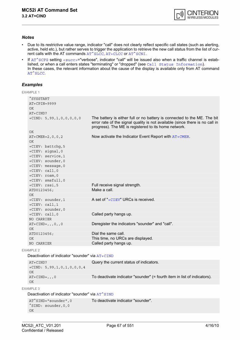
MC52i AT Command Set 3.2 AT+CIND
MC52i_ATC_V01.201 Page 67 of 551 4/16/10Confidential / Released
Notes• Due to its restrictive value range, indicator "call" does not clearly reflect specific call states (such as alerting,
active, held etc.), but rather serves to trigger the application to retrieve the new call status from the list of cur-rent calls with the AT commands AT^SLCC, AT+CLCC or AT^SCNI.
• If AT^SCFG setting <succ>="verbose", indicator "call" will be issued also when a traffic channel is estab-lished, or when a call enters states "terminating" or "dropped" (see Call Status Information).In these cases, the relevant information about the cause of the display is available only from AT commandAT^SLCC.
ExamplesEXAMPLE 1
EXAMPLE 2
Deactivation of indicator "sounder" via AT+CIND
EXAMPLE 3
Deactivation of indicator "sounder" via AT^SIND
^SYSSTARTAT+CPIN=9999OKAT+CIND?+CIND: 5,99,1,0,0,0,0,0 The battery is either full or no battery is connected to the ME. The bit
error rate of the signal quality is not available (since there is no call inprogress). The ME is registered to its home network.
OKAT+CMER=2,0,0,2 Now activate the Indicator Event Report with AT+CMER.OK+CIEV: battchg,5+CIEV: signal,0+CIEV: service,1+CIEV: sounder,0+CIEV: message,0+CIEV: call,0+CIEV: roam,0+CIEV: smsfull,0+CIEV: rssi,5 Full receive signal strength.ATD0123456; Make a call.OK+CIEV: sounder,1 A set of "+CIEV" URCs is received.+CIEV: call,1+CIEV: sounder,0+CIEV: call,0 Called party hangs up.NO CARRIERAT+CIND=,,,0,,0 Deregister the indicators "sounder" and "call".OKATD0123456; Dial the same call.OK This time, no URCs are displayed.NO CARRIER Called party hangs up.
AT+CIND? Query the current status of indicators.+CIND: 5,99,1,0,1,0,0,0,4OKAT+CIND=,,,0 To deactivate indicator "sounder" (= fourth item in list of indicators).OK
AT^SIND="sounder",0 To deactivate indicator "sounder".^SIND: sounder,0,0OK
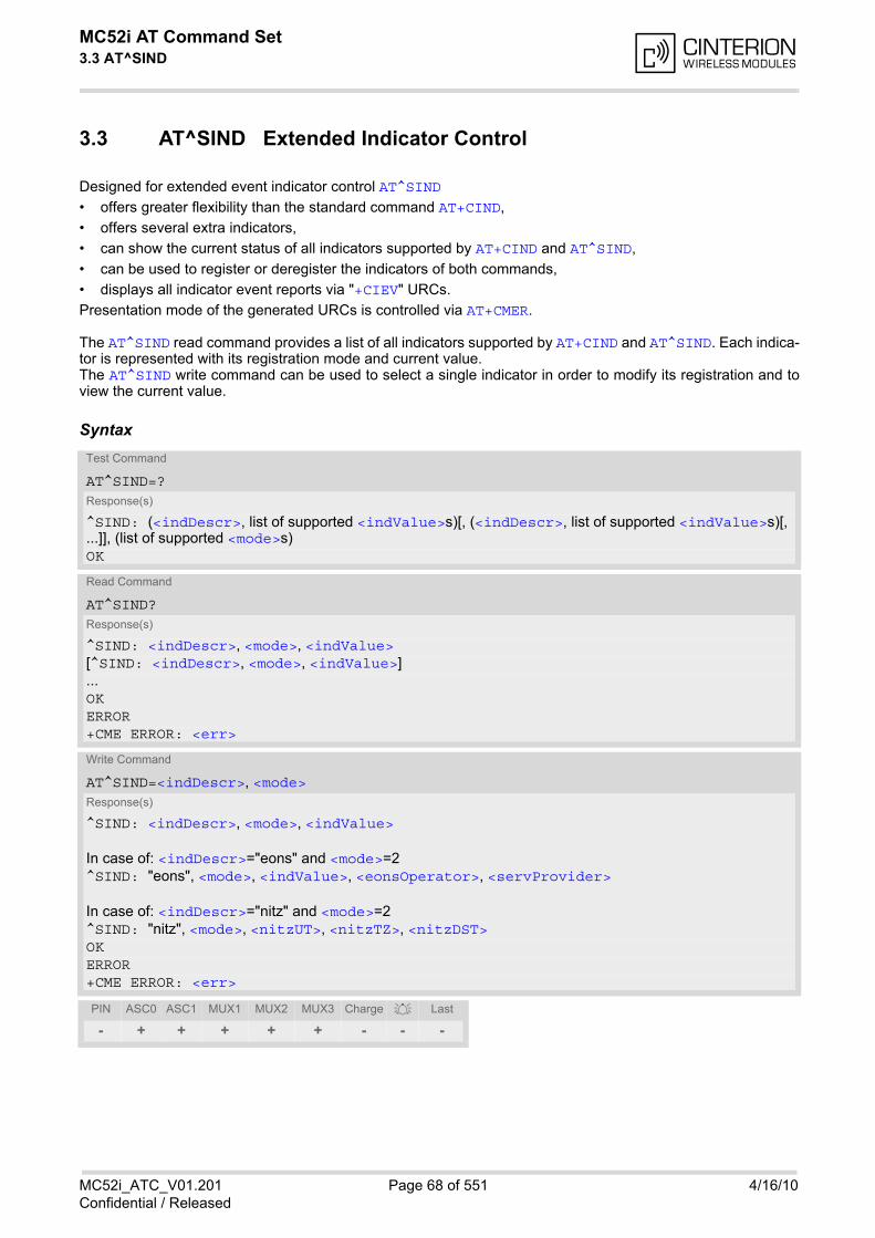
MC52i AT Command Set 3.3 AT^SIND
MC52i_ATC_V01.201 Page 68 of 551 4/16/10Confidential / Released
3.3 AT^SIND Extended Indicator Control
Designed for extended event indicator control AT^SIND
• offers greater flexibility than the standard command AT+CIND,
• offers several extra indicators,
• can show the current status of all indicators supported by AT+CIND and AT^SIND,
• can be used to register or deregister the indicators of both commands,
• displays all indicator event reports via "+CIEV" URCs.
Presentation mode of the generated URCs is controlled via AT+CMER.
The AT^SIND read command provides a list of all indicators supported by AT+CIND and AT^SIND. Each indica-tor is represented with its registration mode and current value. The AT^SIND write command can be used to select a single indicator in order to modify its registration and toview the current value.
SyntaxTest Command
AT^SIND=?Response(s)
^SIND: (<indDescr>, list of supported <indValue>s)[, (<indDescr>, list of supported <indValue>s)[, ...]], (list of supported <mode>s)OK
Read Command
AT^SIND?Response(s)
^SIND: <indDescr>, <mode>, <indValue>[^SIND: <indDescr>, <mode>, <indValue>]...OKERROR+CME ERROR: <err>
Write Command
AT^SIND=<indDescr>, <mode>Response(s)
^SIND: <indDescr>, <mode>, <indValue>
In case of: <indDescr>="eons" and <mode>=2^SIND: "eons", <mode>, <indValue>, <eonsOperator>, <servProvider>
In case of: <indDescr>="nitz" and <mode>=2^SIND: "nitz", <mode>, <nitzUT>, <nitzTZ>, <nitzDST>OKERROR+CME ERROR: <err>
PIN ASC0 ASC1 MUX1 MUX2 MUX3 Charge Last
- + + + + + - - -
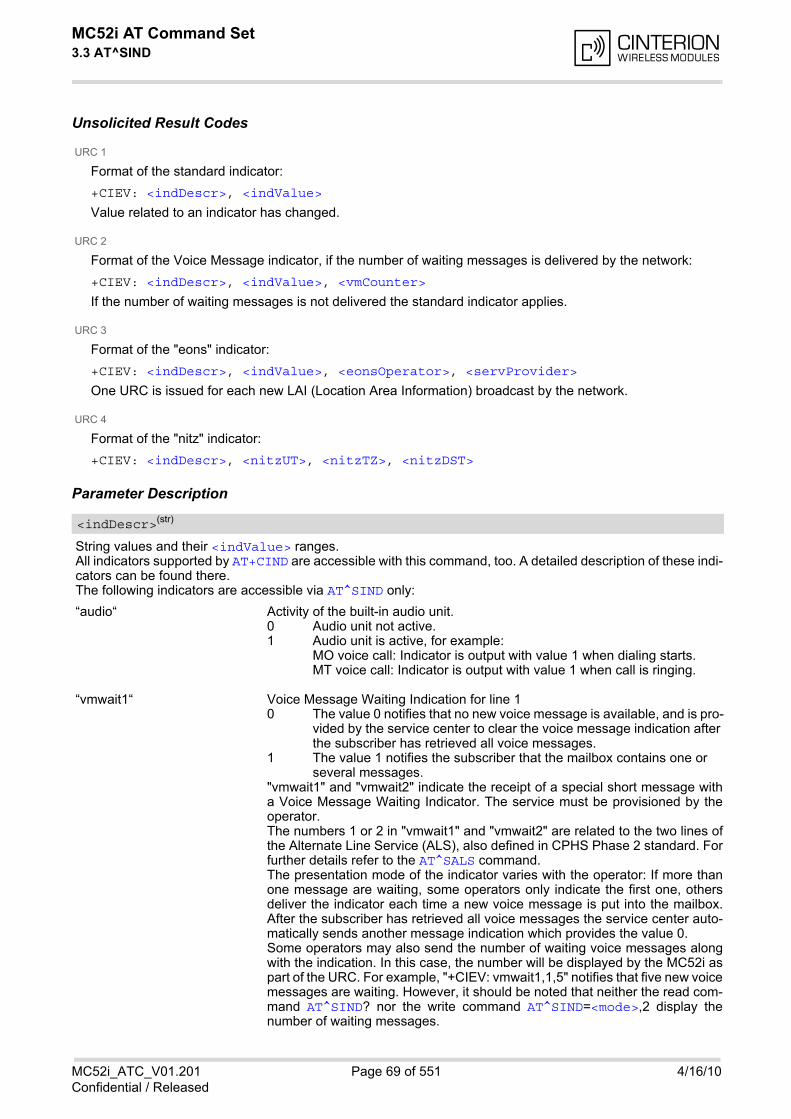
MC52i AT Command Set 3.3 AT^SIND
MC52i_ATC_V01.201 Page 69 of 551 4/16/10Confidential / Released
Unsolicited Result Codes
URC 1
Format of the standard indicator:
+CIEV: <indDescr>, <indValue>
Value related to an indicator has changed.
URC 2
Format of the Voice Message indicator, if the number of waiting messages is delivered by the network:
+CIEV: <indDescr>, <indValue>, <vmCounter>
If the number of waiting messages is not delivered the standard indicator applies.
URC 3
Format of the "eons" indicator:
+CIEV: <indDescr>, <indValue>, <eonsOperator>, <servProvider>
One URC is issued for each new LAI (Location Area Information) broadcast by the network.
URC 4
Format of the "nitz" indicator:
+CIEV: <indDescr>, <nitzUT>, <nitzTZ>, <nitzDST>
Parameter Description
String values and their <indValue> ranges.All indicators supported by AT+CIND are accessible with this command, too. A detailed description of these indi-cators can be found there.The following indicators are accessible via AT^SIND only:
“audio“ Activity of the built-in audio unit.
“vmwait1“ Voice Message Waiting Indication for line 1
"vmwait1" and "vmwait2" indicate the receipt of a special short message witha Voice Message Waiting Indicator. The service must be provisioned by theoperator. The numbers 1 or 2 in "vmwait1" and "vmwait2" are related to the two lines ofthe Alternate Line Service (ALS), also defined in CPHS Phase 2 standard. Forfurther details refer to the AT^SALS command. The presentation mode of the indicator varies with the operator: If more thanone message are waiting, some operators only indicate the first one, othersdeliver the indicator each time a new voice message is put into the mailbox.After the subscriber has retrieved all voice messages the service center auto-matically sends another message indication which provides the value 0. Some operators may also send the number of waiting voice messages alongwith the indication. In this case, the number will be displayed by the MC52i aspart of the URC. For example, "+CIEV: vmwait1,1,5" notifies that five new voicemessages are waiting. However, it should be noted that neither the read com-mand AT^SIND? nor the write command AT^SIND=<mode>,2 display thenumber of waiting messages.
<indDescr>(str)
0 Audio unit not active.1 Audio unit is active, for example:
MO voice call: Indicator is output with value 1 when dialing starts.MT voice call: Indicator is output with value 1 when call is ringing.
0 The value 0 notifies that no new voice message is available, and is pro-vided by the service center to clear the voice message indication after the subscriber has retrieved all voice messages.
1 The value 1 notifies the subscriber that the mailbox contains one or several messages.
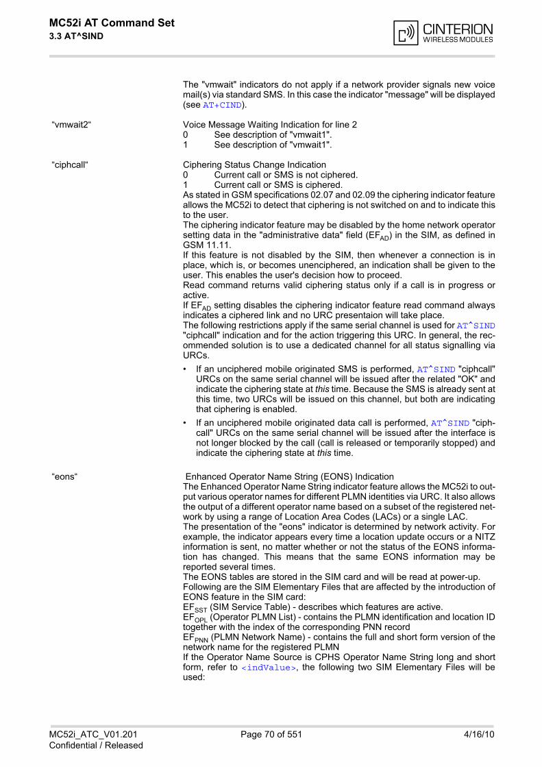
MC52i AT Command Set 3.3 AT^SIND
MC52i_ATC_V01.201 Page 70 of 551 4/16/10Confidential / Released
The "vmwait" indicators do not apply if a network provider signals new voicemail(s) via standard SMS. In this case the indicator "message" will be displayed(see AT+CIND).
“vmwait2“ Voice Message Waiting Indication for line 2
“ciphcall“ Ciphering Status Change Indication
As stated in GSM specifications 02.07 and 02.09 the ciphering indicator featureallows the MC52i to detect that ciphering is not switched on and to indicate thisto the user. The ciphering indicator feature may be disabled by the home network operatorsetting data in the "administrative data" field (EFAD) in the SIM, as defined inGSM 11.11. If this feature is not disabled by the SIM, then whenever a connection is inplace, which is, or becomes unenciphered, an indication shall be given to theuser. This enables the user's decision how to proceed. Read command returns valid ciphering status only if a call is in progress oractive. If EFAD setting disables the ciphering indicator feature read command alwaysindicates a ciphered link and no URC presentaion will take place. The following restrictions apply if the same serial channel is used for AT^SIND"ciphcall" indication and for the action triggering this URC. In general, the rec-ommended solution is to use a dedicated channel for all status signalling viaURCs.
• If an unciphered mobile originated SMS is performed, AT^SIND "ciphcall"URCs on the same serial channel will be issued after the related "OK" andindicate the ciphering state at this time. Because the SMS is already sent atthis time, two URCs will be issued on this channel, but both are indicatingthat ciphering is enabled.
• If an unciphered mobile originated data call is performed, AT^SIND "ciph-call" URCs on the same serial channel will be issued after the interface isnot longer blocked by the call (call is released or temporarily stopped) andindicate the ciphering state at this time.
“eons“ Enhanced Operator Name String (EONS) Indication The Enhanced Operator Name String indicator feature allows the MC52i to out-put various operator names for different PLMN identities via URC. It also allowsthe output of a different operator name based on a subset of the registered net-work by using a range of Location Area Codes (LACs) or a single LAC.The presentation of the "eons" indicator is determined by network activity. Forexample, the indicator appears every time a location update occurs or a NITZinformation is sent, no matter whether or not the status of the EONS informa-tion has changed. This means that the same EONS information may bereported several times.The EONS tables are stored in the SIM card and will be read at power-up. Following are the SIM Elementary Files that are affected by the introduction ofEONS feature in the SIM card:EFSST (SIM Service Table) - describes which features are active. EFOPL (Operator PLMN List) - contains the PLMN identification and location IDtogether with the index of the corresponding PNN record EFPNN (PLMN Network Name) - contains the full and short form version of thenetwork name for the registered PLMN If the Operator Name Source is CPHS Operator Name String long and shortform, refer to <indValue>, the following two SIM Elementary Files will beused:
0 See description of "vmwait1". 1 See description of "vmwait1".
0 Current call or SMS is not ciphered.1 Current call or SMS is ciphered.
MC52i AT Command Set 3.3 AT^SIND
MC52i_ATC_V01.201 Page 71 of 551 4/16/10Confidential / Released
EFONString (Operator Name String) - contains the name of the PLMN operatorwho issued the SIM. EFOPShort (Operator Name Short form) - contains a short form of the name ofthe PLMN operator who issued the SIM.
“nitz“ Network Identity and Time Zone indicationThis indicator shows the time relevant information elements of an MM Informa-tion (MMI) or GMM Information (GMMI) message received from the network(see GSM 24.008, ch. 9.2.15a and 9.4.19). The network usually sends a NITZindicator when the mobile attaches to the network, when it enters a locationarea with different time zone or when a daylight change occurs.A NITZ indicator may consist of the following parameters: Universal Time (UT),local Time Zone (TZ), Daylight Saving Time (DST). All information elements ofMMI/GMMI are optional and therefore, the presentation of the parameters<nitzUT>, <nitzTZ>, <nitzDST> varies with the network. For example, thenetwork may send all three parameters UT, TZ, DST, or only UT and TZ or onlyTZ.
UT is indicated in usual date/time format and represents the current world time(GMT) at the moment when sent.TZ is given as a positive (east) or negative (west) offset from UT in units of 15minutes.DST shows the number of hours added to the local TZ because of daylight sav-ing time (summertime) adjustment. Usually DST is 1 hour but it can be also 2hours in certain locations.
Example for time and time zone with DST:+CIEV: nitz,"04/07/23,13:39:20",-28,1In this example TZ is -28, showing a time offset of -7 hours (west) to UniversalTime/GMT (which never changes for DST). DST is 1 which indicates that onehour was added to TZ because of Daylight Saving Time. If a network does notsend the DST parameter the TZ value would be -32 (8 hours west) as wouldbe done in winter:+CIEV: nitz,"04/11/23,13:39:20",-32
Please be aware that despite the last NITZ value can be looked up again via"AT^SIND=nitz,2" the returned values may be out of date. Especially the UTvalue is obsolete because there is no internal NITZ clock and therefore no con-tinuation of UT.NITZ values are lost when the module detaches from network. Also when amanual network selection fails and the module automatically falls back to theprevious network the NITZ values cannot be recalled. Nevertheless an indi-cated time zone is valid until a new MMI/GMMI will trigger another NITZ indi-cation.
Integer type value in the range stated above for the corresponding <indDescr>.
Notes specific to the EONS feature: If the indicator is "eons", the <indValue> is a type associated to the operator name according to GSM 22.101[23]. This type depends on the source of the operator name. Priority of types associated to the operator names is defined as follows (the type listed first has the highest pri-ority). If a type cannot be indicated the next one will be used.
<indValue>(num)
0 Not registered.1 EF-OPL and EF-PNN (alphanumeric format, can contain up to 24 characters.)2 Operator Name String in long and short format according to Common PCN
Handset Specification (CPHS) [24] (alphanumeric format, can contain up to 16 characters).
MC52i AT Command Set 3.3 AT^SIND
MC52i_ATC_V01.201 Page 72 of 551 4/16/10Confidential / Released
If the type is 2, 4 or 5, AT+COPS with the appropriate <mode> displays the same operator name.
0 Indicator is deregistered, i.e. no such indicator event report (URC) will beissued. <mode>=0 is power-up and factory default of indicators defined byAT^SIND only.
1 Indicator is registered.
• Indicator event reports are controlled via AT+CMER.
• All indicators can be registered or deregistered via AT^SIND, but differentdefault settings apply: Power-up and factory default of the indicators sup-ported by AT+CIND is <mode>=1, while, as stated above, indicators definedby AT^SIND only are set to <mode>=0.
2 Query the registration status and the current value of a single indicator type.
If delivered by the network: Number of new voice messages sent as part of the Voice Message Waiting Indicator.Refer to <indDescr>.
Operator in format which depends on the type associated to the operator name. Refer to <indValue>.
Service Provider Name according to the status settings (SIM Service No. 17) in the SIM Service Table (SST) ofthe SIM.
Universal Time delivered as part of the "nitz" Indicator. Refer to <indDescr>.
Time Zone delivered as part of the "nitz" Indicator. Refer to <indDescr>.
Adjustment for Daylight Saving Time as part of the "nitz" Indicator. Refer to <indDescr>.
Example
Activation and use of indicator "audio":
3 Name information received by the NITZ service long and short form (alphanu-meric format, can contain up to 16 characters). The short form will be displayed only if EFOPShort from CPHS is available.
4 Any operator name stored internal to the ME (alphanumeric format, can con-tain up to 16 characters).
5 Broadcast MCC-MNC (numeric format which consists of a 3-digit country code plus a 2- or 3-digit network code).
<mode>(num)
<vmCounter>
<eonsOperator>
<servProvider>(str)
<nitzUT>
<nitzTZ>
<nitzDST>
AT^SIND="audio",1 You register the indicator "audio".^SIND: audio,1,0OKAT+CMER=2,,,2 You activate the Indicator Event Report with AT+CMER.OK A set of all registered URCs is presented. (Please note that the example
includes the indicators registered due to the power-up default settingsof AT+CIND.)
MC52i AT Command Set 3.3 AT^SIND
MC52i_ATC_V01.201 Page 73 of 551 4/16/10Confidential / Released
+CIEV: battchg,5+CIEV: signal,0+CIEV: service,1+CIEV: sounder,0+CIEV: message,1+CIEV: call,0+CIEV: roam,0+CIEV: smsfull,0+CIEV: rssi,4+CIEV: audio,0ATD030123456; You make a call.OK+CIEV: audio,1+CIEV: sounder,1+CIEV: call,1+CIEV: signal,0+CIEV: sounder,0ATH You hang up.OK+CIEV: call,0+CIEV: rssi,3+CIEV: audio,0+CIEV: signal,0+CIEV: rssi,4
MC52i AT Command Set 3.4 AT+CEER
MC52i_ATC_V01.201 Page 74 of 551 4/16/10Confidential / Released
3.4 AT+CEER Extended Error Report
AT+CEER returns an extended error report regarding the reason of the last
• call release
• failure to set up a call (both mobile originated or terminated)
• failure to modify a call by using Supplementary Services
• failed attempt to activate, register, query, deactivate or deregister a Supplementary Service
• unsuccessful GPRS attach or unsuccessful PDP context activation
• GPRS detach or PDP context deactivation
The release cause report is presented in numeric format. Default output in case of a none-error-situation is+CEER: 0,0,0. A description associated with each number can be found in the tables given in the following sub-clauses and the relevant GSM specifications. The first parameter <locationID> serves to locate the other two parameters. Depending on the failure orrelease cause either <reason> or <ssRelease> are applicable, i.e. if <reason> 0, then <ssRelease> = 0.Vice versa, if <reason> = 0, then <ssRelease> may be 0. In addition to AT+CEER, the command ATS18 can be used to check especially the status of fax and data calls. When losing network coverage the MC52i will disconnect the call. In this case, no network release cause is avail-able, and AT+CEER returns only the default values +CEER: 0,0,0.
Syntax
Parameter Description
Location ID as number code. Location IDs are listed in Section 3.4.1, Cause Location ID for the extended errorreport. Each ID is related with another table that contains a list of <reason>s or <ssRelease>s.
Reason for last call release as number code. The number codes are listed in several tables, sorted by differentcategories in the following subclauses. The tables can be found proceeding from the Location ID given in Sec-tion 3.4.1, Cause Location ID for the extended error report.
Test Command
AT+CEER=?Response(s)
OKERROR+CME ERROR: <err>
Exec Command
AT+CEERResponse(s)
+CEER: <locationID>, <reason>, <ssRelease>OKERROR+CME ERROR: <err>
PIN ASC0 ASC1 MUX1 MUX2 MUX3 Charge Last Reference(s)
+ + + + + + - - - GSM 07.07
<locationID>(num)
<reason>(num)
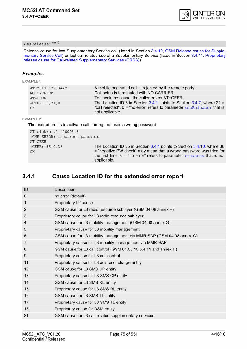
MC52i AT Command Set 3.4 AT+CEER
MC52i_ATC_V01.201 Page 75 of 551 4/16/10Confidential / Released
Release cause for last Supplementary Service call (listed in Section 3.4.10, GSM Release cause for Supple-mentary Service Call) or last call related use of a Supplementary Service (listed in Section 3.4.11, Proprietaryrelease cause for Call-related Supplementary Services (CRSS)).
ExamplesEXAMPLE 1
EXAMPLE 2
The user attempts to activate call barring, but uses a wrong password.
3.4.1 Cause Location ID for the extended error report
<ssRelease>(num)
ATD"01751223344"; A mobile originated call is rejected by the remote party. NO CARRIER Call setup is terminated with NO CARRIER. AT+CEER To check the cause, the caller enters AT+CEER. +CEER: 8,21,0 The Location ID 8 in Section 3.4.1 points to Section 3.4.7, where 21 =
"call rejected". 0 = "no error" refers to parameter <ssRelease> that isnot applicable.
OK
AT+clck=oi,1,"0000",3+CME ERROR: incorrect passwordAT+CEER+CEER: 35,0,38 The Location ID 35 in Section 3.4.1 points to Section 3.4.10, where 38
= "negative PW check" may mean that a wrong password was tried forthe first time. 0 = "no error" refers to parameter <reason> that is notapplicable.
OK
ID Description
0 no error (default)
1 Proprietary L2 cause
2 GSM cause for L3 radio resource sublayer (GSM 04.08 annex F)
3 Proprietary cause for L3 radio resource sublayer
4 GSM cause for L3 mobility management (GSM 04.08 annex G)
5 Proprietary cause for L3 mobility management
6 GSM cause for L3 mobility management via MMR-SAP (GSM 04.08 annex G)
7 Proprietary cause for L3 mobility management via MMR-SAP
8 GSM cause for L3 call control (GSM 04.08 10.5.4.11 and annex H)
9 Proprietary cause for L3 call control
11 Proprietary cause for L3 advice of charge entity
12 GSM cause for L3 SMS CP entity
13 Proprietary cause for L3 SMS CP entity
14 GSM cause for L3 SMS RL entity
15 Proprietary cause for L3 SMS RL entity
16 GSM cause for L3 SMS TL entity
17 Proprietary cause for L3 SMS TL entity
18 Proprietary cause for DSM entity
21 GSM cause for L3 call-related supplementary services

MC52i AT Command Set 3.4 AT+CEER
MC52i_ATC_V01.201 Page 76 of 551 4/16/10Confidential / Released
3.4.2 Proprietary L2 cause
3.4.3 GSM release cause for L3 Radio Resource (RR)
22 Proprietary cause for L3 call-related supplementary services
32 Proprietary cause for supplementary services entity
33 Proprietary cause for supplementary services manager
34 network cause for supplementary services (GSM 04.08 10.5.4.11 and annex H)
35 supplementary services network error (GSM 04.80 3.6.6)
48 GSM cause for GPRS mobility management (GSM 04.08 annex G.6)
49 Proprietary cause for GPRS mobility management
50 GSM cause for session management (GSM 04.08 annex I)
51 Proprietary cause for session management
127 Proprietary cause for protocol module or other local cause
128 supplementary services general problem (GSM 04.80 3.6.7)
129 supplementary services invoke problem (GSM 04.80 3.6.7)
130 supplementary services result problem (GSM 04.80 3.6.7)
131 supplementary services error problem (GSM 04.80 3.6.7)
241 Proprietary cause for GPRS API
242 Proprietary cause for link management
243 Proprietary cause for PPP/IP-stack
Number Description
249 no network response received, e.g. due to low signal quality
Number Description
0 normal event
1 abnormal release, unspecified
2 abnormal release, channel unacceptable
3 abnormal release, timer expired
4 abnormal release, no activity on the radio path
5 pre-emptive release
8 handover impossible, timing advance out of range
9 channel mode unacceptable
10 frequency not implemented
65 call already cleared
95 semantically incorrect message
96 invalid mandatory information
97 message type non-existent or not implemented
98 message type not compatible with protocol state
ID Description
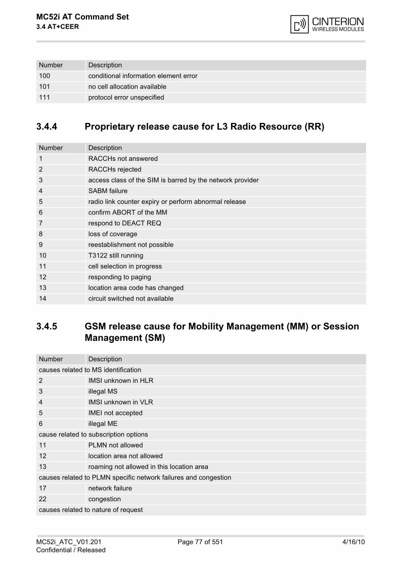
MC52i AT Command Set 3.4 AT+CEER
MC52i_ATC_V01.201 Page 77 of 551 4/16/10Confidential / Released
3.4.4 Proprietary release cause for L3 Radio Resource (RR)
3.4.5 GSM release cause for Mobility Management (MM) or Session Management (SM)
100 conditional information element error
101 no cell allocation available
111 protocol error unspecified
Number Description
1 RACCHs not answered
2 RACCHs rejected
3 access class of the SIM is barred by the network provider
4 SABM failure
5 radio link counter expiry or perform abnormal release
6 confirm ABORT of the MM
7 respond to DEACT REQ
8 loss of coverage
9 reestablishment not possible
10 T3122 still running
11 cell selection in progress
12 responding to paging
13 location area code has changed
14 circuit switched not available
Number Description
causes related to MS identification
2 IMSI unknown in HLR
3 illegal MS
4 IMSI unknown in VLR
5 IMEI not accepted
6 illegal ME
cause related to subscription options
11 PLMN not allowed
12 location area not allowed
13 roaming not allowed in this location area
causes related to PLMN specific network failures and congestion
17 network failure
22 congestion
causes related to nature of request
Number Description
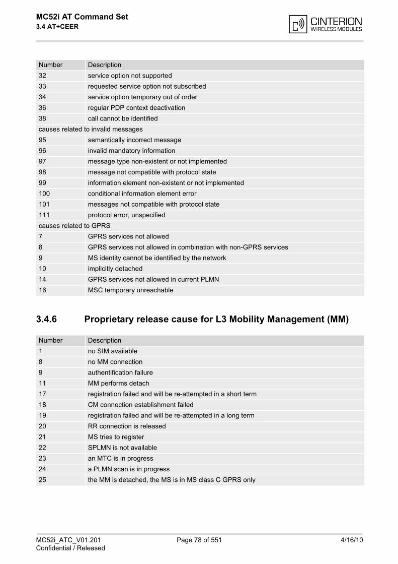
MC52i AT Command Set 3.4 AT+CEER
MC52i_ATC_V01.201 Page 78 of 551 4/16/10Confidential / Released
3.4.6 Proprietary release cause for L3 Mobility Management (MM)
32 service option not supported
33 requested service option not subscribed
34 service option temporary out of order
36 regular PDP context deactivation
38 call cannot be identified
causes related to invalid messages
95 semantically incorrect message
96 invalid mandatory information
97 message type non-existent or not implemented
98 message not compatible with protocol state
99 information element non-existent or not implemented
100 conditional information element error
101 messages not compatible with protocol state
111 protocol error, unspecified
causes related to GPRS
7 GPRS services not allowed
8 GPRS services not allowed in combination with non-GPRS services
9 MS identity cannot be identified by the network
10 implicitly detached
14 GPRS services not allowed in current PLMN
16 MSC temporary unreachable
Number Description
1 no SIM available
8 no MM connection
9 authentification failure
11 MM performs detach
17 registration failed and will be re-attempted in a short term
18 CM connection establishment failed
19 registration failed and will be re-attempted in a long term
20 RR connection is released
21 MS tries to register
22 SPLMN is not available
23 an MTC is in progress
24 a PLMN scan is in progress
25 the MM is detached, the MS is in MS class C GPRS only
Number Description

MC52i AT Command Set 3.4 AT+CEER
MC52i_ATC_V01.201 Page 79 of 551 4/16/10Confidential / Released
3.4.7 GSM release cause for L3 Call Control (CC)
Number Description
0 no error
normal class
1 unassigned (unallocated) number
2 service not available
3 no route to destination
6 channel unacceptable
8 operator determined barring
9 FDN mismatch
16 normal call clearing
17 user busy
18 no user responding
19 user alerting, no answer
21 call rejected
22 number changed
25 pre-emption
26 non-selected user clearing
27 destination out of order
28 invalid number format (incomplete number)
29 facility rejected
30 response to STATUS ENQUIRY
31 normal, unspecified
resource unavailable class
34 no circuit/channel available
38 network out of order
41 temporary failure
42 switching equipment congestion
43 access information discarded
44 requested circuit/channel not available
47 resource unavailable, unspecified
service or option not available class
49 quality of service unavailable
50 requested facility not subscribed
55 incoming calls barred within the CUG
57 bearer capability not authorized
58 bearer capability not presently available
63 service or option not available, unspecified
service or option not implemented
65 bearer service not implemented
68 ACM equal or greater than ACM max
69 requested facility not implemented
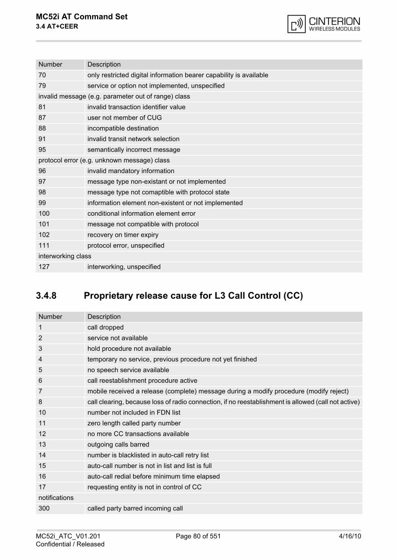
MC52i AT Command Set 3.4 AT+CEER
MC52i_ATC_V01.201 Page 80 of 551 4/16/10Confidential / Released
3.4.8 Proprietary release cause for L3 Call Control (CC)
70 only restricted digital information bearer capability is available
79 service or option not implemented, unspecified
invalid message (e.g. parameter out of range) class
81 invalid transaction identifier value
87 user not member of CUG
88 incompatible destination
91 invalid transit network selection
95 semantically incorrect message
protocol error (e.g. unknown message) class
96 invalid mandatory information
97 message type non-existant or not implemented
98 message type not comaptible with protocol state
99 information element non-existent or not implemented
100 conditional information element error
101 message not compatible with protocol
102 recovery on timer expiry
111 protocol error, unspecified
interworking class
127 interworking, unspecified
Number Description
1 call dropped
2 service not available
3 hold procedure not available
4 temporary no service, previous procedure not yet finished
5 no speech service available
6 call reestablishment procedure active
7 mobile received a release (complete) message during a modify procedure (modify reject)
8 call clearing, because loss of radio connection, if no reestablishment is allowed (call not active)
10 number not included in FDN list
11 zero length called party number
12 no more CC transactions available
13 outgoing calls barred
14 number is blacklisted in auto-call retry list
15 auto-call number is not in list and list is full
16 auto-call redial before minimum time elapsed
17 requesting entity is not in control of CC
notifications
300 called party barred incoming call
Number Description

MC52i AT Command Set 3.4 AT+CEER
MC52i_ATC_V01.201 Page 81 of 551 4/16/10Confidential / Released
3.4.9 Proprietary release cause for L3 Advice of Charge (AOC)
3.4.10 GSM Release cause for Supplementary Service Call
Number Description
1 SIM data not available
2 SIM does not support AOC
3 SIM data access error
4 ACM limit almost reached ACM range overflow
5 ACM range overflow
Number Description
0 no error (default)
1 unknown subscriber
9 illegal subscriber
10 bearer service not provisioned
11 teleservice not provisioned
12 illegal equipment
13 call barred
15 CUG reject
16 illegal SS operation
17 SS error status
18 SS not available
19 SS subscription violation
20 SS incompatibility
21 facility not supported
27 absent subscriber
29 short term denial
30 long term denial
34 system failure
35 data missing
36 unexpected data value
37 PW registration failure
38 negative PW check
43 number of PW attempts violation
71 unknown alphabet
72 USSD busy
126 max nums of MPTY calls exceeded
127 resources not available
general problem codes
300 unrecognized component
301 mistyped component
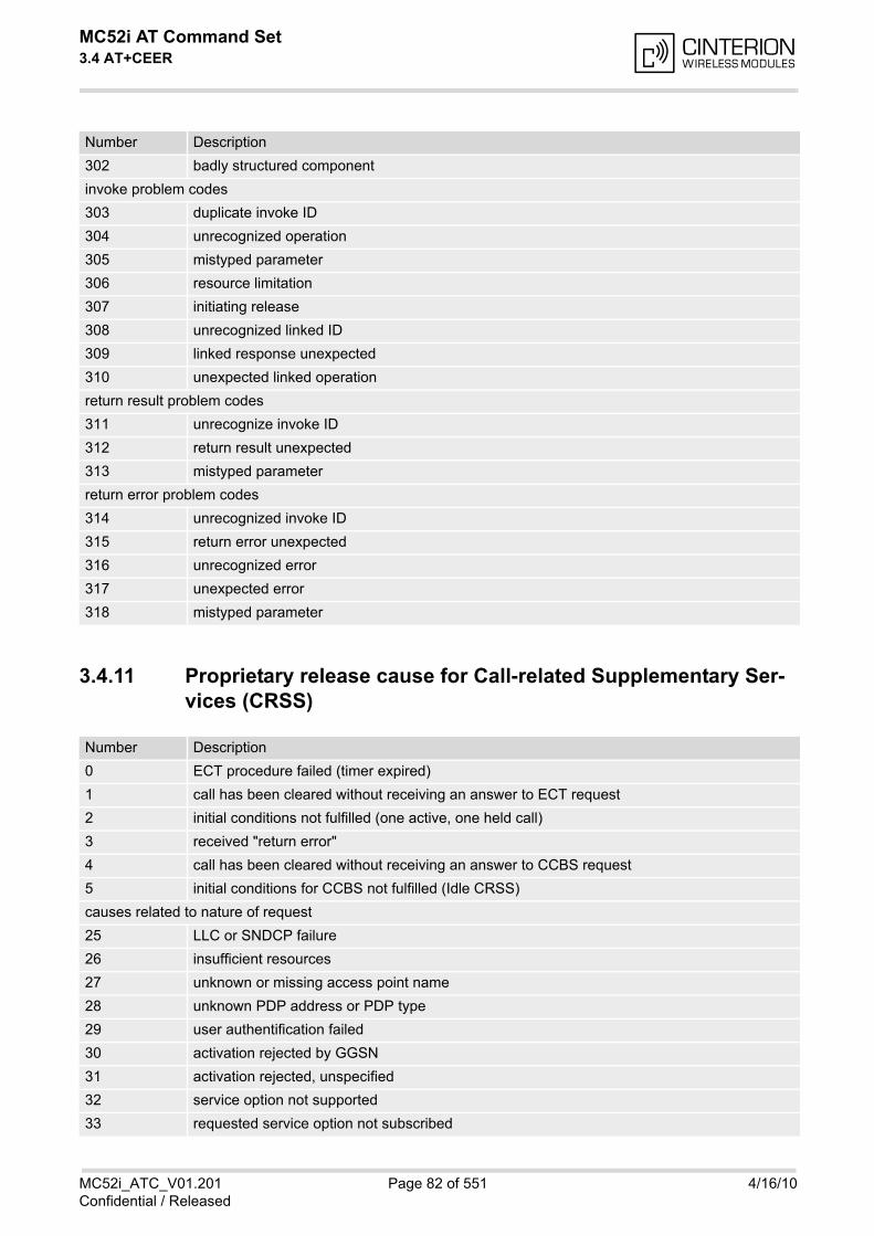
MC52i AT Command Set 3.4 AT+CEER
MC52i_ATC_V01.201 Page 82 of 551 4/16/10Confidential / Released
3.4.11 Proprietary release cause for Call-related Supplementary Ser-vices (CRSS)
302 badly structured component
invoke problem codes
303 duplicate invoke ID
304 unrecognized operation
305 mistyped parameter
306 resource limitation
307 initiating release
308 unrecognized linked ID
309 linked response unexpected
310 unexpected linked operation
return result problem codes
311 unrecognize invoke ID
312 return result unexpected
313 mistyped parameter
return error problem codes
314 unrecognized invoke ID
315 return error unexpected
316 unrecognized error
317 unexpected error
318 mistyped parameter
Number Description
0 ECT procedure failed (timer expired)
1 call has been cleared without receiving an answer to ECT request
2 initial conditions not fulfilled (one active, one held call)
3 received "return error"
4 call has been cleared without receiving an answer to CCBS request
5 initial conditions for CCBS not fulfilled (Idle CRSS)
causes related to nature of request
25 LLC or SNDCP failure
26 insufficient resources
27 unknown or missing access point name
28 unknown PDP address or PDP type
29 user authentification failed
30 activation rejected by GGSN
31 activation rejected, unspecified
32 service option not supported
33 requested service option not subscribed
Number Description

MC52i AT Command Set 3.4 AT+CEER
MC52i_ATC_V01.201 Page 83 of 551 4/16/10Confidential / Released
3.4.12 Proprietary release cause for Session Management (SM)
3.4.13 GSM cause for L3 Protocol module or other local cause
34 service option temporary out of order
35 NSAPI already used
36 regular PDP context deactivation
37 QoS not accepted
38 network failure
39 reactivation requested
40 feature not supported
causes related to invalid messages
81 invalid transaction identifier value
95 semantically incorrect message
96 invalid mandatory information
97 message type non-existant or not implemented
98 message type not comaptible with protocol state
99 information element non-existent or not implemented
100 conditional information element error
101 message not compatible with protocol
111 protocol error, unspecified
Number Description
3 the MS has not got any answer to the ACTIVATE PDP CONTEXT request message sent five times to the network
4 a MT PDP context which is active or in the activation process is deactivated because another MT PDP context with the same TI is requested by the network to be activated
5 a MT PDP context which is active or in the activation process is deactivated because another MT PDP context with the same TI is requested by the network to be activated. The activation request is rejected by the SM sending the cause 'insufficient resources' to the network because the SM was not able to perform the necessary comparisons for a static PDP address collision detection.
6 a MT PDP context which is active or in the activation process is deactivated because another MT PDP context with the same TI is requested by the network to be activated. As a static PDP address collision with an MO activating PDP context has been detected by the SM the SM dis-cards the activation request
7 a MT PDP context request has been indicated but could not be processed in time. The activa-tion request is rejected by the SM sending the cause 'insufficient resources' to the network.
Number Description
2 no detailed cause
Number Description
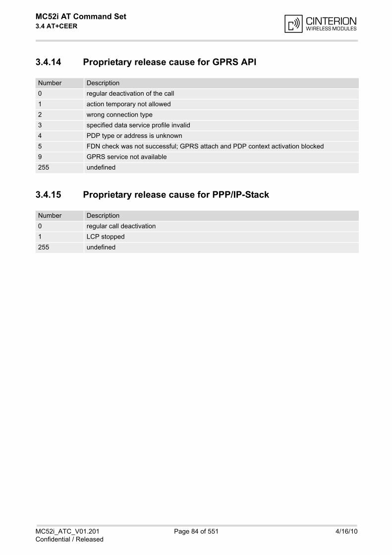
MC52i AT Command Set 3.4 AT+CEER
MC52i_ATC_V01.201 Page 84 of 551 4/16/10Confidential / Released
3.4.14 Proprietary release cause for GPRS API
3.4.15 Proprietary release cause for PPP/IP-Stack
Number Description
0 regular deactivation of the call
1 action temporary not allowed
2 wrong connection type
3 specified data service profile invalid
4 PDP type or address is unknown
5 FDN check was not successful; GPRS attach and PDP context activation blocked
9 GPRS service not available
255 undefined
Number Description
0 regular call deactivation
1 LCP stopped
255 undefined
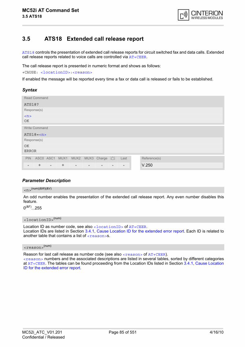
MC52i AT Command Set 3.5 ATS18
MC52i_ATC_V01.201 Page 85 of 551 4/16/10Confidential / Released
3.5 ATS18 Extended call release report
ATS18 controls the presentation of extended call release reports for circuit switched fax and data calls. Extendedcall release reports related to voice calls are controlled via AT+CEER.
The call release report is presented in numeric format and shows as follows:
If enabled the message will be reported every time a fax or data call is released or fails to be established.
Syntax
Parameter Description
An odd number enables the presentation of the extended call release report. Any even number disables thisfeature.
0(&F)...255
Location ID as number code, see also <locationID> of AT+CEER. Location IDs are listed in Section 3.4.1, Cause Location ID for the extended error report. Each ID is related toanother table that contains a list of <reason>s.
Reason for last call release as number code (see also <reason> of AT+CEER).<reason> numbers and the associated descriptions are listed in several tables, sorted by different categoriesat AT+CEER. The tables can be found proceeding from the Location IDs listed in Section 3.4.1, Cause LocationID for the extended error report.
+CAUSE: <locationID>:<reason>
Read Command
ATS18?Response(s)
<n>OK
Write Command
ATS18=<n>Response(s)
OKERROR
PIN ASC0 ASC1 MUX1 MUX2 MUX3 Charge Last Reference(s)
- + - + - - - - - V.250
<n>(num)(&W)(&V)
<locationID>(num)
<reason>(num)
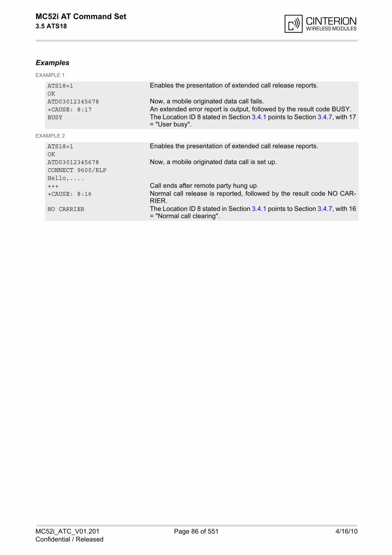
MC52i AT Command Set 3.5 ATS18
MC52i_ATC_V01.201 Page 86 of 551 4/16/10Confidential / Released
ExamplesEXAMPLE 1
EXAMPLE 2
ATS18=1 Enables the presentation of extended call release reports.OKATD03012345678 Now, a mobile originated data call fails.+CAUSE: 8:17 An extended error report is output, followed by the result code BUSY.BUSY The Location ID 8 stated in Section 3.4.1 points to Section 3.4.7, with 17
= "User busy".
ATS18=1 Enables the presentation of extended call release reports.OKATD03012345678 Now, a mobile originated data call is set up.CONNECT 9600/RLPHello,....+++ Call ends after remote party hung up.+CAUSE: 8:16 Normal call release is reported, followed by the result code NO CAR-
RIER.NO CARRIER The Location ID 8 stated in Section 3.4.1 points to Section 3.4.7, with 16
= "Normal call clearing".
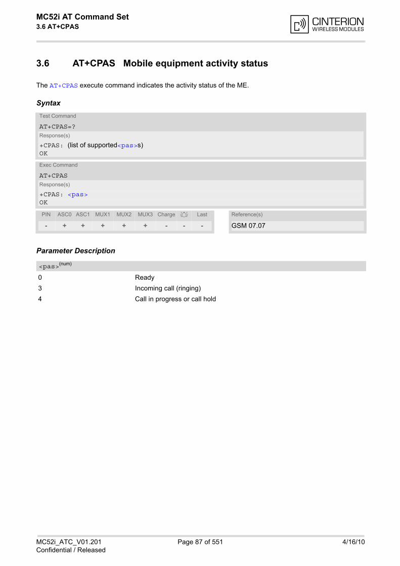
MC52i AT Command Set 3.6 AT+CPAS
MC52i_ATC_V01.201 Page 87 of 551 4/16/10Confidential / Released
3.6 AT+CPAS Mobile equipment activity status
The AT+CPAS execute command indicates the activity status of the ME.
Syntax
Parameter Description
0 Ready
3 Incoming call (ringing)
4 Call in progress or call hold
Test Command
AT+CPAS=?Response(s)
+CPAS: (list of supported<pas>s)OK
Exec Command
AT+CPASResponse(s)
+CPAS: <pas>OK
PIN ASC0 ASC1 MUX1 MUX2 MUX3 Charge Last Reference(s)
- + + + + + - - - GSM 07.07
<pas>(num)

MC52i AT Command Set 3.7 AT+WS46
MC52i_ATC_V01.201 Page 88 of 551 4/16/10Confidential / Released
3.7 AT+WS46 Select wireless network
Syntax
Parameter Description
12 GSM digital cellular
Test Command
AT+WS46=?Response(s)
+WS46: (list of supported<n>s)OK
Read Command
AT+WS46?Response(s)
<n>OK
Write Command
AT+WS46=[<n>]Response(s)
OKERROR+CME ERROR: <err>
PIN ASC0 ASC1 MUX1 MUX2 MUX3 Charge Last Reference(s)
- + + + + + - - - GSM 07.07
<n>(num)
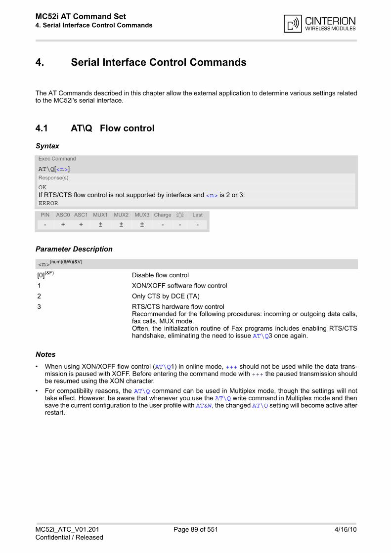
MC52i AT Command Set 4. Serial Interface Control Commands
MC52i_ATC_V01.201 Page 89 of 551 4/16/10Confidential / Released
4. Serial Interface Control Commands
The AT Commands described in this chapter allow the external application to determine various settings relatedto the MC52i's serial interface.
4.1 AT\Q Flow control
Syntax
Parameter Description
[0](&F) Disable flow control
1 XON/XOFF software flow control
2 Only CTS by DCE (TA)
3 RTS/CTS hardware flow controlRecommended for the following procedures: incoming or outgoing data calls,fax calls, MUX mode.Often, the initialization routine of Fax programs includes enabling RTS/CTShandshake, eliminating the need to issue AT\Q3 once again.
Notes• When using XON/XOFF flow control (AT\Q1) in online mode, +++ should not be used while the data trans-
mission is paused with XOFF. Before entering the command mode with +++ the paused transmission shouldbe resumed using the XON character.
• For compatibility reasons, the AT\Q command can be used in Multiplex mode, though the settings will nottake effect. However, be aware that whenever you use the AT\Q write command in Multiplex mode and thensave the current configuration to the user profile with AT&W, the changed AT\Q setting will become active afterrestart.
Exec Command
AT\Q[<n>]Response(s)
OKIf RTS/CTS flow control is not supported by interface and <n> is 2 or 3:ERROR
PIN ASC0 ASC1 MUX1 MUX2 MUX3 Charge Last
- + + ± ± ± - - -
<n>(num)(&W)(&V)
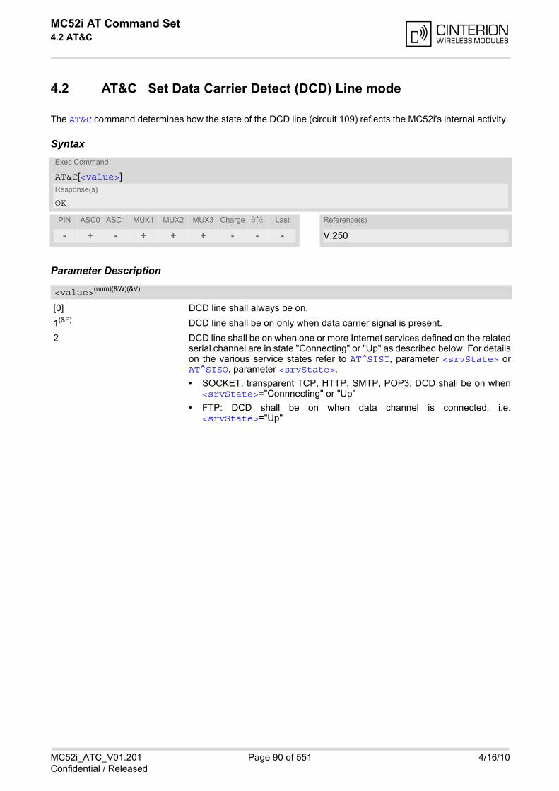
MC52i AT Command Set 4.2 AT&C
MC52i_ATC_V01.201 Page 90 of 551 4/16/10Confidential / Released
4.2 AT&C Set Data Carrier Detect (DCD) Line mode
The AT&C command determines how the state of the DCD line (circuit 109) reflects the MC52i's internal activity.
Syntax
Parameter Description
[0] DCD line shall always be on.
1(&F) DCD line shall be on only when data carrier signal is present.
2 DCD line shall be on when one or more Internet services defined on the relatedserial channel are in state "Connecting" or "Up" as described below. For detailson the various service states refer to AT^SISI, parameter <srvState> orAT^SISO, parameter <srvState>.
• SOCKET, transparent TCP, HTTP, SMTP, POP3: DCD shall be on when<srvState>="Connnecting" or "Up"
• FTP: DCD shall be on when data channel is connected, i.e.<srvState>="Up"
Exec Command
AT&C[<value>]Response(s)
OK
PIN ASC0 ASC1 MUX1 MUX2 MUX3 Charge Last Reference(s)
- + - + + + - - - V.250
<value>(num)(&W)(&V)
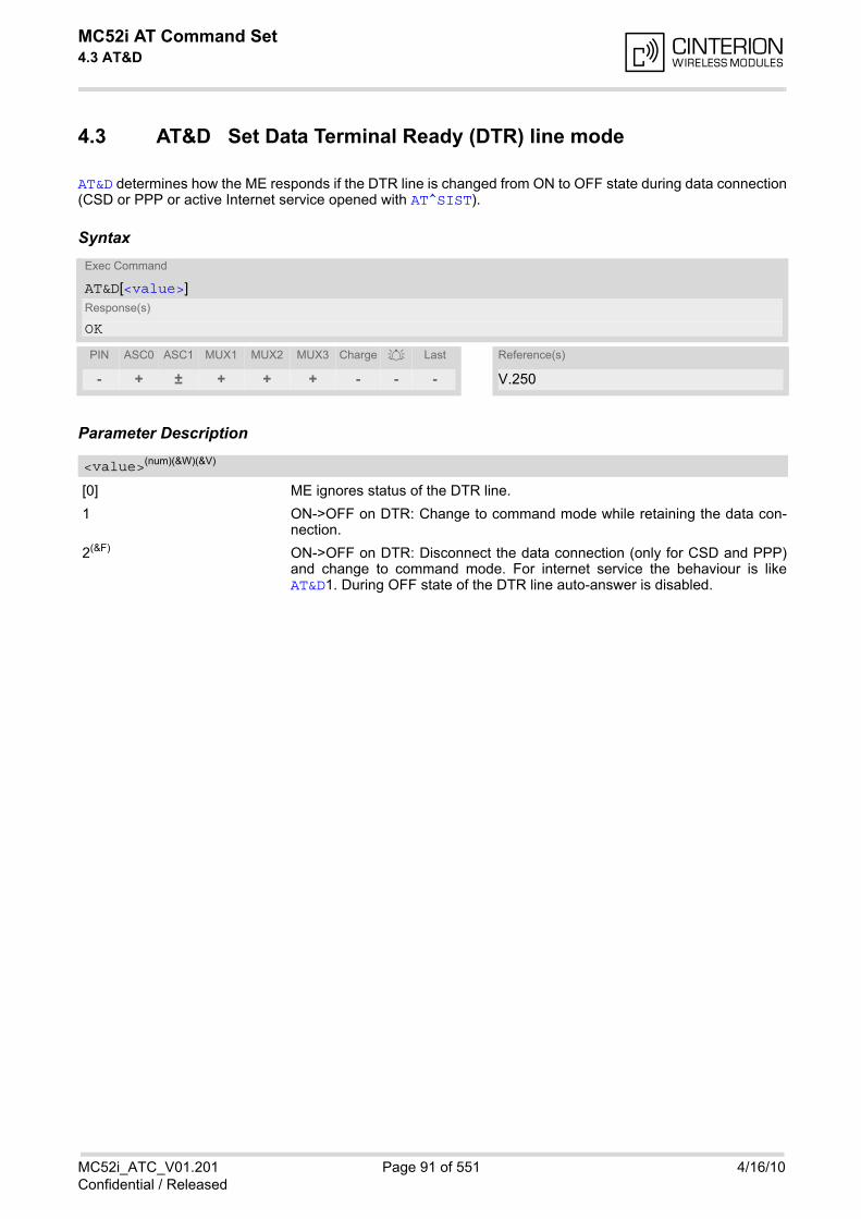
MC52i AT Command Set 4.3 AT&D
MC52i_ATC_V01.201 Page 91 of 551 4/16/10Confidential / Released
4.3 AT&D Set Data Terminal Ready (DTR) line mode
AT&D determines how the ME responds if the DTR line is changed from ON to OFF state during data connection(CSD or PPP or active Internet service opened with AT^SIST).
Syntax
Parameter Description
[0] ME ignores status of the DTR line.
1 ON->OFF on DTR: Change to command mode while retaining the data con-nection.
2(&F) ON->OFF on DTR: Disconnect the data connection (only for CSD and PPP)and change to command mode. For internet service the behaviour is likeAT&D1. During OFF state of the DTR line auto-answer is disabled.
Exec Command
AT&D[<value>]Response(s)
OK
PIN ASC0 ASC1 MUX1 MUX2 MUX3 Charge Last Reference(s)
- + ± + + + - - - V.250
<value>(num)(&W)(&V)
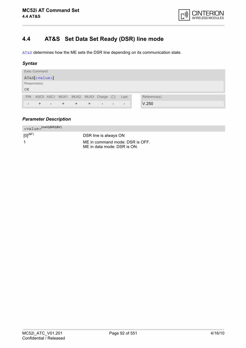
MC52i AT Command Set 4.4 AT&S
MC52i_ATC_V01.201 Page 92 of 551 4/16/10Confidential / Released
4.4 AT&S Set Data Set Ready (DSR) line mode
AT&S determines how the ME sets the DSR line depending on its communication state.
Syntax
Parameter Description
[0](&F) DSR line is always ON
1 ME in command mode: DSR is OFF.ME in data mode: DSR is ON.
Exec Command
AT&S[<value>]Response(s)
OK
PIN ASC0 ASC1 MUX1 MUX2 MUX3 Charge Last Reference(s)
- + - + + + - - - V.250
<value>(num)(&W)(&V)
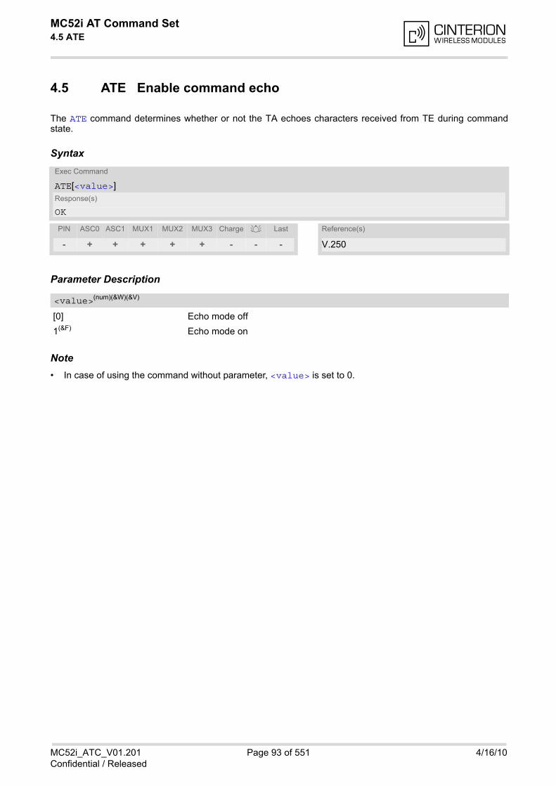
MC52i AT Command Set 4.5 ATE
MC52i_ATC_V01.201 Page 93 of 551 4/16/10Confidential / Released
4.5 ATE Enable command echo
The ATE command determines whether or not the TA echoes characters received from TE during commandstate.
Syntax
Parameter Description
[0] Echo mode off
1(&F) Echo mode on
Note• In case of using the command without parameter, <value> is set to 0.
Exec Command
ATE[<value>]Response(s)
OK
PIN ASC0 ASC1 MUX1 MUX2 MUX3 Charge Last Reference(s)
- + + + + + - - - V.250
<value>(num)(&W)(&V)

MC52i AT Command Set 4.6 AT+ILRR
MC52i_ATC_V01.201 Page 94 of 551 4/16/10Confidential / Released
4.6 AT+ILRR Set TE-TA local rate reporting
The command AT+ILRR controls whether or not the intermediate result code "+ILRR" is transmitted from the TAto the TE while a connection is being set up. The result code indicates the local rate. It is issued before the finalresult code of the connection, e.g. CONNECT, is transmitted to the TE.
Syntax
Intermediate Result Code+ILRR: <rate>
Indicates local port rate setting upon connection setup.
Parameter Description
0(&F) Disables reporting of local port rate
1 Enables reporting of local port rate
Port rate setting upon connection setup (bps)
0 Autobauding (see Section 4.7.1, Autobauding). Not supported on ASC1.
300
600
1200
2400
4800
9600
14400
Test Command
AT+ILRR=?Response(s)
+ILRR: (list of supported <value>s) OK
Read Command
AT+ILRR?Response(s)
+ILRR: <value>OK
Write Command
AT+ILRR=<value>Response(s)
OKERROR+CME ERROR: <err>
PIN ASC0 ASC1 MUX1 MUX2 MUX3 Charge Last Reference(s)
+ + - + - - - - - V.250
<value>(num)(&W)(&V)
<rate>(num)
MC52i AT Command Set 4.6 AT+ILRR
MC52i_ATC_V01.201 Page 95 of 551 4/16/10Confidential / Released
19200
28800
38400
57600
115200
230400 (Not permitted for MC52i Terminal)
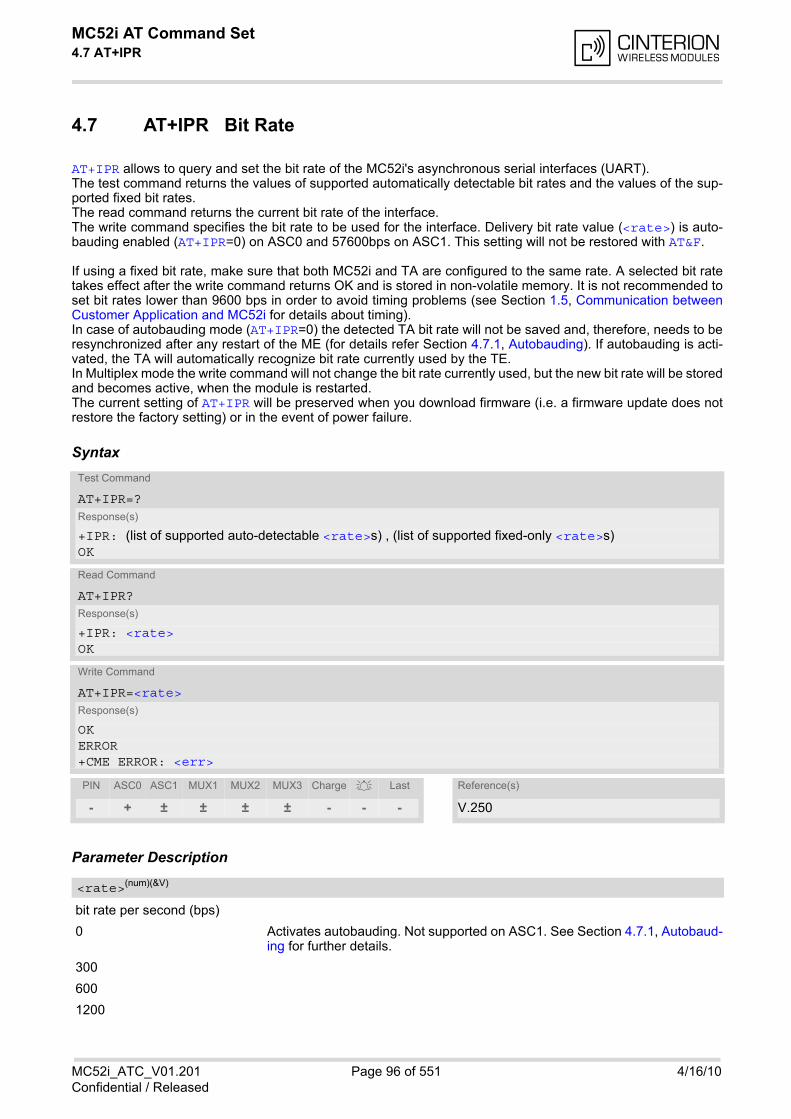
MC52i AT Command Set 4.7 AT+IPR
MC52i_ATC_V01.201 Page 96 of 551 4/16/10Confidential / Released
4.7 AT+IPR Bit Rate
AT+IPR allows to query and set the bit rate of the MC52i's asynchronous serial interfaces (UART). The test command returns the values of supported automatically detectable bit rates and the values of the sup-ported fixed bit rates. The read command returns the current bit rate of the interface. The write command specifies the bit rate to be used for the interface. Delivery bit rate value (<rate>) is auto-bauding enabled (AT+IPR=0) on ASC0 and 57600bps on ASC1. This setting will not be restored with AT&F.
If using a fixed bit rate, make sure that both MC52i and TA are configured to the same rate. A selected bit ratetakes effect after the write command returns OK and is stored in non-volatile memory. It is not recommended toset bit rates lower than 9600 bps in order to avoid timing problems (see Section 1.5, Communication betweenCustomer Application and MC52i for details about timing). In case of autobauding mode (AT+IPR=0) the detected TA bit rate will not be saved and, therefore, needs to beresynchronized after any restart of the ME (for details refer Section 4.7.1, Autobauding). If autobauding is acti-vated, the TA will automatically recognize bit rate currently used by the TE. In Multiplex mode the write command will not change the bit rate currently used, but the new bit rate will be storedand becomes active, when the module is restarted. The current setting of AT+IPR will be preserved when you download firmware (i.e. a firmware update does notrestore the factory setting) or in the event of power failure.
Syntax
Parameter Description
bit rate per second (bps)
0 Activates autobauding. Not supported on ASC1. See Section 4.7.1, Autobaud-ing for further details.
300
600
1200
Test Command
AT+IPR=?Response(s)
+IPR: (list of supported auto-detectable <rate>s) , (list of supported fixed-only <rate>s)OK
Read Command
AT+IPR?Response(s)
+IPR: <rate>OK
Write Command
AT+IPR=<rate>Response(s)
OKERROR+CME ERROR: <err>
PIN ASC0 ASC1 MUX1 MUX2 MUX3 Charge Last Reference(s)
- + ± ± ± ± - - - V.250
<rate>(num)(&V)
MC52i AT Command Set 4.7 AT+IPR
MC52i_ATC_V01.201 Page 97 of 551 4/16/10Confidential / Released
2400
4800
9600
14400
19200
28800
38400
57600
115200
230400 (Not permitted for MC52i Terminal)
Note• Generally, AT+IPR should be used as a standalone command as specified in Section 1.4.2, Concatenating
AT Commands. If nevertheless combinations with other commands on the same command line cannot beavoided, there are several constraints to be considered:
- Avoid combinations with the AT commands listed in Section 1.4.2, Concatenating AT Commands.
- Keep in mind that there shall be a minimum pause between two AT commands as specified in Section 1.5,Communication between Customer Application and MC52i.
- If AT+IPR=0 is entered, autobauding will be activated after the response to the last command is received.
- If local echo is active (ATE1) and AT+IPR=x is entered with other commands you may encounter the fol-lowing problem: If switching to the new bit rate takes effect while a response is being transmitted, the lastbytes may be sent with the new bit rate and thus, not properly transmitted. The following commands willbe correctly sent at the new bit rate.
4.7.1 Autobauding
To take advantage of autobaud mode specific attention must be paid to the following requirements:
• Synchronization between TE and TA:Ensure that TE and TA are correctly synchronized and the bit rate used by the TE is detected by the TA. Toallow the bit rate to be synchronized simply use an "AT" or "at" string. This is necessary
- after you have activated autobauding
- when you start up the ME while autobauding is enabled. It is recommended to wait 3 to 5 seconds beforesending the first AT character. Otherwise undefined characters might be returned.
If you want to use autobauding and autoanswer at the same time, you can easily enable the TE-TA synchro-nization, when you activate autobauding first and then configure the autoanswer mode (ATS0 0).
• Restrictions on autobauding operation:
- The serial interface shall be used with 8 data bits, no parity and 1 stop bit (factory setting), e.g. 2 stop bitsare not supported for autobaud mode.
- The command A/ cannot be used.
- Only the strings "AT" or "at" can be detected (neither "At" nor "aT").
- The second serial interface ASC1 does not support autobauding.
- URCs that may be issued before the ME detects a new bit rate (by receiving the first AT character) will besent at the previously detected bit rate or, after ME restart, at 57600 bps.
- It is not recommended to switch to autobauding from a bit rate that cannot be detected by the autobaudmechanism (e.g. 300 bps). Responses to AT+IPR=0 and any commands on the same line might be cor-rupted.
- MC52i Terminal version: autobauding MUST NOT be used at bit rates over 115200bps.
• Autobauding and bit rate after restart:Unless the bit rate is determined, the following constraints apply:
MC52i AT Command Set 4.7 AT+IPR
MC52i_ATC_V01.201 Page 98 of 551 4/16/10Confidential / Released
- An incoming CSD call or a network initiated GPRS request cannot be accepted. This must be taken intoaccount when autobauding and autoanswer mode (ATS0 0) are enabled at the same time, escpeciallyif SIM PIN 1 authentication is done automatically and the setting ATS0 0 is stored to the user profile withAT&W.
- Until the bit rate is found, URCs generated after restart will be output at 57600 bps. This applies only touser defined URCs, such as "+CREG", "CCWA", "^SCKS" etc. The URCs "^SYSSTART", "^SYSSTARTCHARGE-ONLY MODE" and "^SYSSTART ALARM MODE" will not be indicated when autobauding isenabled.
Note: To avoid any problems caused by undetermined bit rates in the direction from TA to TE we stronglyrecommend to configure a fixed bit rate rather than autobauding.
• Autobauding and multiplex mode:If autobauding is active you cannot switch to multiplex mode (see AT+CMUX).
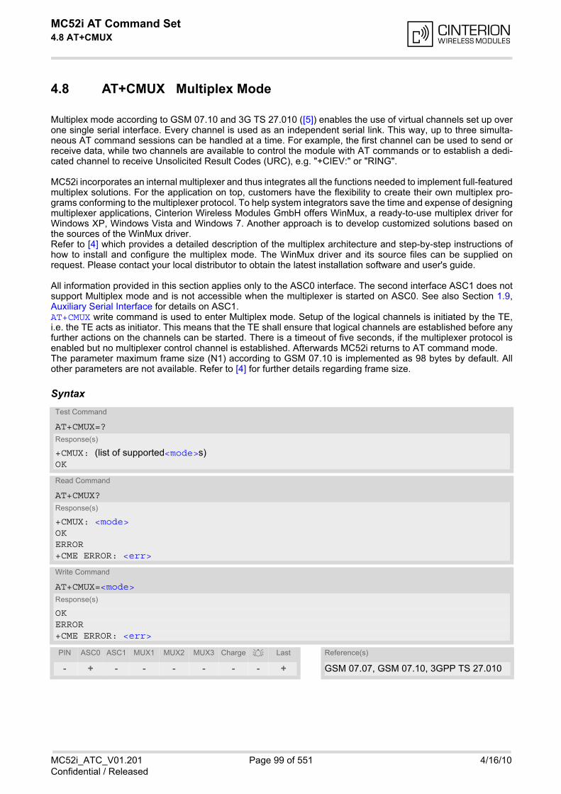
MC52i AT Command Set 4.8 AT+CMUX
MC52i_ATC_V01.201 Page 99 of 551 4/16/10Confidential / Released
4.8 AT+CMUX Multiplex Mode
Multiplex mode according to GSM 07.10 and 3G TS 27.010 ([5]) enables the use of virtual channels set up overone single serial interface. Every channel is used as an independent serial link. This way, up to three simulta-neous AT command sessions can be handled at a time. For example, the first channel can be used to send orreceive data, while two channels are available to control the module with AT commands or to establish a dedi-cated channel to receive Unsolicited Result Codes (URC), e.g. "+CIEV:" or "RING".
MC52i incorporates an internal multiplexer and thus integrates all the functions needed to implement full-featuredmultiplex solutions. For the application on top, customers have the flexibility to create their own multiplex pro-grams conforming to the multiplexer protocol. To help system integrators save the time and expense of designingmultiplexer applications, Cinterion Wireless Modules GmbH offers WinMux, a ready-to-use multiplex driver forWindows XP, Windows Vista and Windows 7. Another approach is to develop customized solutions based onthe sources of the WinMux driver.Refer to [4] which provides a detailed description of the multiplex architecture and step-by-step instructions ofhow to install and configure the multiplex mode. The WinMux driver and its source files can be supplied onrequest. Please contact your local distributor to obtain the latest installation software and user's guide.
All information provided in this section applies only to the ASC0 interface. The second interface ASC1 does notsupport Multiplex mode and is not accessible when the multiplexer is started on ASC0. See also Section 1.9,Auxiliary Serial Interface for details on ASC1. AT+CMUX write command is used to enter Multiplex mode. Setup of the logical channels is initiated by the TE,i.e. the TE acts as initiator. This means that the TE shall ensure that logical channels are established before anyfurther actions on the channels can be started. There is a timeout of five seconds, if the multiplexer protocol isenabled but no multiplexer control channel is established. Afterwards MC52i returns to AT command mode. The parameter maximum frame size (N1) according to GSM 07.10 is implemented as 98 bytes by default. Allother parameters are not available. Refer to [4] for further details regarding frame size.
SyntaxTest Command
AT+CMUX=?Response(s)
+CMUX: (list of supported<mode>s)OK
Read Command
AT+CMUX?Response(s)
+CMUX: <mode>OKERROR+CME ERROR: <err>
Write Command
AT+CMUX=<mode>Response(s)
OKERROR+CME ERROR: <err>
PIN ASC0 ASC1 MUX1 MUX2 MUX3 Charge Last Reference(s)
- + - - - - - - + GSM 07.07, GSM 07.10, 3GPP TS 27.010
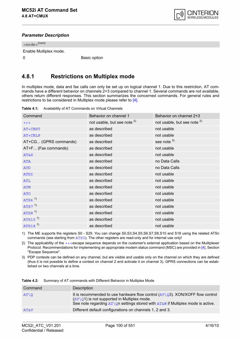
MC52i AT Command Set 4.8 AT+CMUX
MC52i_ATC_V01.201 Page 100 of 551 4/16/10Confidential / Released
Parameter Description
Enable Multiplex mode.
0 Basic option
4.8.1 Restrictions on Multiplex mode
In multiplex mode, data and fax calls can only be set up on logical channel 1. Due to this restriction, AT com-mands have a different behavior on channels 2+3 compared to channel 1. Several commands are not available,others return different responses. This section summarizes the concerned commands. For general rules andrestrictions to be considered in Multiplex mode please refer to [4].
Table 4.1: Availability of AT Commands on Virtual Channels
1) The ME supports the registers S0 - S29. You can change S0,S3,S4,S5,S6,S7,S8,S10 and S18 using the related ATSncommands (see starting from ATS0). The other registers are read-only and for internal use only!
2) The applicability of the +++escape sequence depends on the customer's external application based on the MulitplexerProtocol. Recommendations for implementing an appropriate modem status command (MSC) are provided in [4], Section"Escape Sequence".
3) PDP contexts can be defined on any channel, but are visible and usable only on the channel on which they are defined(thus it is not possible to define a context on channel 2 and activate it on channel 3). GPRS connections can be estab-lished on two channels at a time.
Table 4.2: Summary of AT commands with Different Behavior in Multiplex Mode
<mode>(num)
Command Behavior on channel 1 Behavior on channel 2+3
+++ not usable, but see note 2) not usable, but see note 2)
AT+CBST as described not usable
AT+CRLP as described not usable
AT+CG... (GPRS commands) as described see note 3)
AT+F... (Fax commands) as described not usable
AT&S as described not usable
ATA as described no Data Calls
ATD as described no Data Calls
ATDI as described not usable
ATL as described not usable
ATM as described not usable
ATO as described not usable
ATS6 1) as described not usable
ATS7 1) as described not usable
ATS8 1) as described not usable
ATS10 1) as described not usable
ATS18 1) as described not usable
Command Description
AT\Q It is recommended to use hardware flow control (AT\Q3). XON/XOFF flow control (AT\Q1) is not supported in Multiplex mode.See note regarding AT\Qn settings stored with AT&W if Multiplex mode is active.
AT&V Different default configurations on channels 1, 2 and 3.
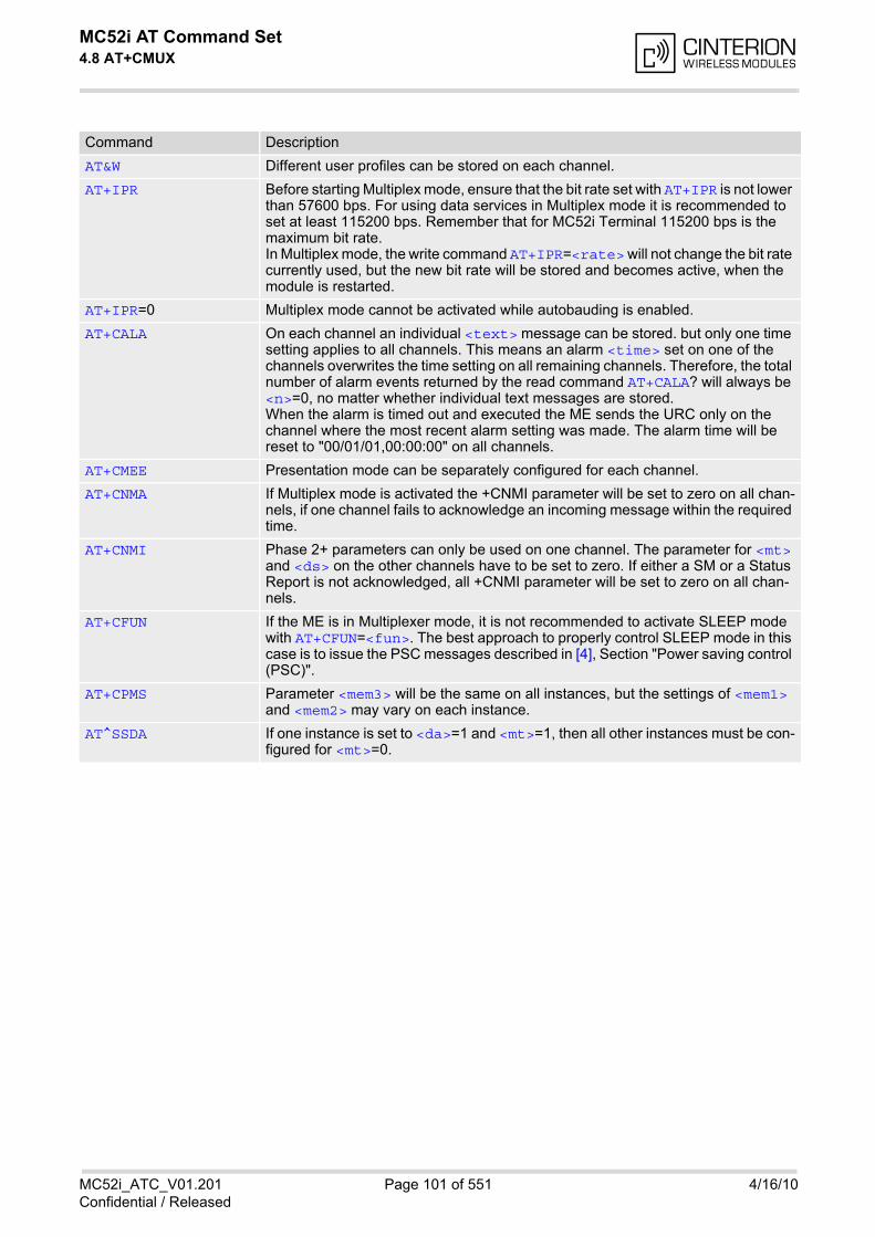
MC52i AT Command Set 4.8 AT+CMUX
MC52i_ATC_V01.201 Page 101 of 551 4/16/10Confidential / Released
AT&W Different user profiles can be stored on each channel.
AT+IPR Before starting Multiplex mode, ensure that the bit rate set with AT+IPR is not lower than 57600 bps. For using data services in Multiplex mode it is recommended to set at least 115200 bps. Remember that for MC52i Terminal 115200 bps is the maximum bit rate. In Multiplex mode, the write command AT+IPR=<rate> will not change the bit rate currently used, but the new bit rate will be stored and becomes active, when the module is restarted.
AT+IPR=0 Multiplex mode cannot be activated while autobauding is enabled.
AT+CALA On each channel an individual <text> message can be stored. but only one time setting applies to all channels. This means an alarm <time> set on one of the channels overwrites the time setting on all remaining channels. Therefore, the total number of alarm events returned by the read command AT+CALA? will always be <n>=0, no matter whether individual text messages are stored.When the alarm is timed out and executed the ME sends the URC only on the channel where the most recent alarm setting was made. The alarm time will be reset to "00/01/01,00:00:00" on all channels.
AT+CMEE Presentation mode can be separately configured for each channel.
AT+CNMA If Multiplex mode is activated the +CNMI parameter will be set to zero on all chan-nels, if one channel fails to acknowledge an incoming message within the required time.
AT+CNMI Phase 2+ parameters can only be used on one channel. The parameter for <mt> and <ds> on the other channels have to be set to zero. If either a SM or a Status Report is not acknowledged, all +CNMI parameter will be set to zero on all chan-nels.
AT+CFUN If the ME is in Multiplexer mode, it is not recommended to activate SLEEP mode with AT+CFUN=<fun>. The best approach to properly control SLEEP mode in this case is to issue the PSC messages described in [4], Section "Power saving control (PSC)".
AT+CPMS Parameter <mem3> will be the same on all instances, but the settings of <mem1> and <mem2> may vary on each instance.
AT^SSDA If one instance is set to <da>=1 and <mt>=1, then all other instances must be con-figured for <mt>=0.
Command Description
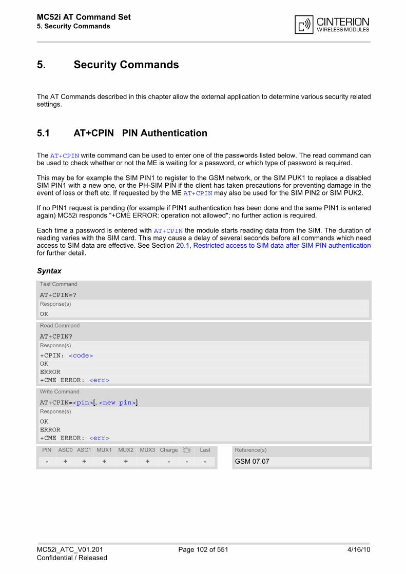
MC52i AT Command Set 5. Security Commands
MC52i_ATC_V01.201 Page 102 of 551 4/16/10Confidential / Released
5. Security Commands
The AT Commands described in this chapter allow the external application to determine various security relatedsettings.
5.1 AT+CPIN PIN Authentication
The AT+CPIN write command can be used to enter one of the passwords listed below. The read command canbe used to check whether or not the ME is waiting for a password, or which type of password is required.
This may be for example the SIM PIN1 to register to the GSM network, or the SIM PUK1 to replace a disabledSIM PIN1 with a new one, or the PH-SIM PIN if the client has taken precautions for preventing damage in theevent of loss or theft etc. If requested by the ME AT+CPIN may also be used for the SIM PIN2 or SIM PUK2.
If no PIN1 request is pending (for example if PIN1 authentication has been done and the same PIN1 is enteredagain) MC52i responds "+CME ERROR: operation not allowed"; no further action is required.
Each time a password is entered with AT+CPIN the module starts reading data from the SIM. The duration ofreading varies with the SIM card. This may cause a delay of several seconds before all commands which needaccess to SIM data are effective. See Section 20.1, Restricted access to SIM data after SIM PIN authenticationfor further detail.
SyntaxTest Command
AT+CPIN=?Response(s)
OK
Read Command
AT+CPIN?Response(s)
+CPIN: <code>OK ERROR +CME ERROR: <err>
Write Command
AT+CPIN=<pin>[, <new pin>]Response(s)
OK ERROR +CME ERROR: <err>
PIN ASC0 ASC1 MUX1 MUX2 MUX3 Charge Last Reference(s)
- + + + + + - - - GSM 07.07
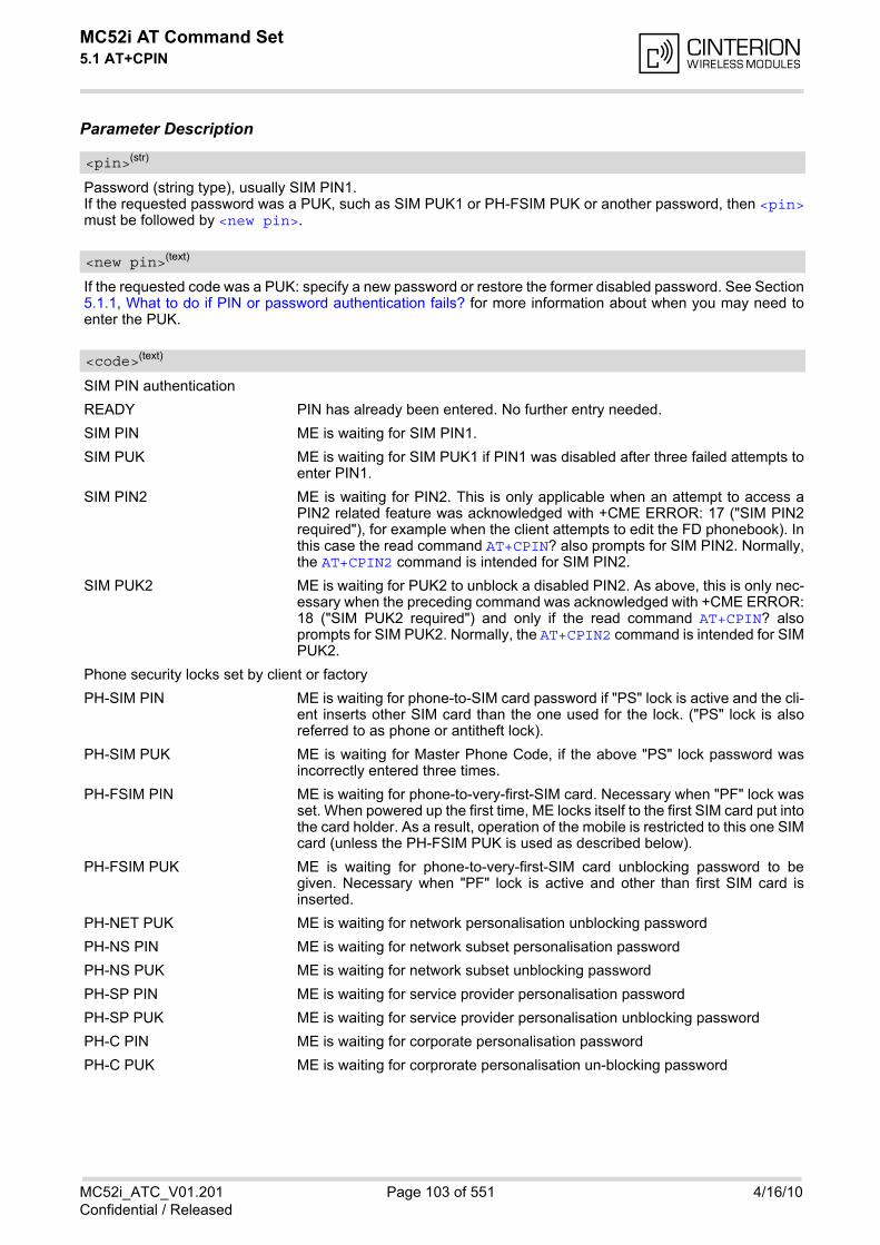
MC52i AT Command Set 5.1 AT+CPIN
MC52i_ATC_V01.201 Page 103 of 551 4/16/10Confidential / Released
Parameter Description
Password (string type), usually SIM PIN1.If the requested password was a PUK, such as SIM PUK1 or PH-FSIM PUK or another password, then <pin>must be followed by <new pin>.
If the requested code was a PUK: specify a new password or restore the former disabled password. See Section5.1.1, What to do if PIN or password authentication fails? for more information about when you may need toenter the PUK.
SIM PIN authentication
READY PIN has already been entered. No further entry needed.
SIM PIN ME is waiting for SIM PIN1.
SIM PUK ME is waiting for SIM PUK1 if PIN1 was disabled after three failed attempts toenter PIN1.
SIM PIN2 ME is waiting for PIN2. This is only applicable when an attempt to access aPIN2 related feature was acknowledged with +CME ERROR: 17 ("SIM PIN2required"), for example when the client attempts to edit the FD phonebook). Inthis case the read command AT+CPIN? also prompts for SIM PIN2. Normally,the AT+CPIN2 command is intended for SIM PIN2.
SIM PUK2 ME is waiting for PUK2 to unblock a disabled PIN2. As above, this is only nec-essary when the preceding command was acknowledged with +CME ERROR:18 ("SIM PUK2 required") and only if the read command AT+CPIN? alsoprompts for SIM PUK2. Normally, the AT+CPIN2 command is intended for SIMPUK2.
Phone security locks set by client or factory
PH-SIM PIN ME is waiting for phone-to-SIM card password if "PS" lock is active and the cli-ent inserts other SIM card than the one used for the lock. ("PS" lock is alsoreferred to as phone or antitheft lock).
PH-SIM PUK ME is waiting for Master Phone Code, if the above "PS" lock password wasincorrectly entered three times.
PH-FSIM PIN ME is waiting for phone-to-very-first-SIM card. Necessary when "PF" lock wasset. When powered up the first time, ME locks itself to the first SIM card put intothe card holder. As a result, operation of the mobile is restricted to this one SIMcard (unless the PH-FSIM PUK is used as described below).
PH-FSIM PUK ME is waiting for phone-to-very-first-SIM card unblocking password to begiven. Necessary when "PF" lock is active and other than first SIM card isinserted.
PH-NET PUK ME is waiting for network personalisation unblocking password
PH-NS PIN ME is waiting for network subset personalisation password
PH-NS PUK ME is waiting for network subset unblocking password
PH-SP PIN ME is waiting for service provider personalisation password
PH-SP PUK ME is waiting for service provider personalisation unblocking password
PH-C PIN ME is waiting for corporate personalisation password
PH-C PUK ME is waiting for corprorate personalisation un-blocking password
<pin>(str)
<new pin>(text)
<code>(text)
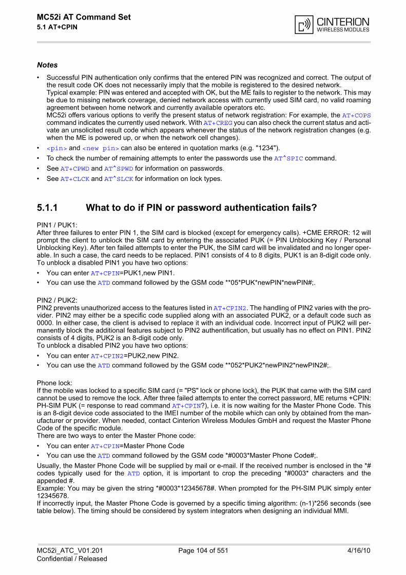
MC52i AT Command Set 5.1 AT+CPIN
MC52i_ATC_V01.201 Page 104 of 551 4/16/10Confidential / Released
Notes• Successful PIN authentication only confirms that the entered PIN was recognized and correct. The output of
the result code OK does not necessarily imply that the mobile is registered to the desired network.Typical example: PIN was entered and accepted with OK, but the ME fails to register to the network. This maybe due to missing network coverage, denied network access with currently used SIM card, no valid roamingagreement between home network and currently available operators etc.MC52i offers various options to verify the present status of network registration: For example, the AT+COPScommand indicates the currently used network. With AT+CREG you can also check the current status and acti-vate an unsolicited result code which appears whenever the status of the network registration changes (e.g.when the ME is powered up, or when the network cell changes).
• <pin> and <new pin> can also be entered in quotation marks (e.g. "1234").
• To check the number of remaining attempts to enter the passwords use the AT^SPIC command.
• See AT+CPWD and AT^SPWD for information on passwords.
• See AT+CLCK and AT^SLCK for information on lock types.
5.1.1 What to do if PIN or password authentication fails?
PIN1 / PUK1:After three failures to enter PIN 1, the SIM card is blocked (except for emergency calls). +CME ERROR: 12 willprompt the client to unblock the SIM card by entering the associated PUK (= PIN Unblocking Key / PersonalUnblocking Key). After ten failed attempts to enter the PUK, the SIM card will be invalidated and no longer oper-able. In such a case, the card needs to be replaced. PIN1 consists of 4 to 8 digits, PUK1 is an 8-digit code only.To unblock a disabled PIN1 you have two options:
• You can enter AT+CPIN=PUK1,new PIN1.
• You can use the ATD command followed by the GSM code **05*PUK*newPIN*newPIN#;.
PIN2 / PUK2: PIN2 prevents unauthorized access to the features listed in AT+CPIN2. The handling of PIN2 varies with the pro-vider. PIN2 may either be a specific code supplied along with an associated PUK2, or a default code such as0000. In either case, the client is advised to replace it with an individual code. Incorrect input of PUK2 will per-manently block the additional features subject to PIN2 authentification, but usually has no effect on PIN1. PIN2consists of 4 digits, PUK2 is an 8-digit code only.To unblock a disabled PIN2 you have two options:
• You can enter AT+CPIN2=PUK2,new PIN2.
• You can use the ATD command followed by the GSM code **052*PUK2*newPIN2*newPIN2#;.
Phone lock: If the mobile was locked to a specific SIM card (= "PS" lock or phone lock), the PUK that came with the SIM cardcannot be used to remove the lock. After three failed attempts to enter the correct password, ME returns +CPIN:PH-SIM PUK (= response to read command AT+CPIN?), i.e. it is now waiting for the Master Phone Code. Thisis an 8-digit device code associated to the IMEI number of the mobile which can only by obtained from the man-ufacturer or provider. When needed, contact Cinterion Wireless Modules GmbH and request the Master PhoneCode of the specific module.There are two ways to enter the Master Phone code:
• You can enter AT+CPIN=Master Phone Code
• You can use the ATD command followed by the GSM code *#0003*Master Phone Code#;.
Usually, the Master Phone Code will be supplied by mail or e-mail. If the received number is enclosed in the *#codes typically used for the ATD option, it is important to crop the preceding *#0003* characters and theappended #. Example: You may be given the string *#0003*12345678#. When prompted for the PH-SIM PUK simply enter12345678.If incorrectly input, the Master Phone Code is governed by a specific timing algorithm: (n-1)*256 seconds (seetable below). The timing should be considered by system integrators when designing an individual MMI.
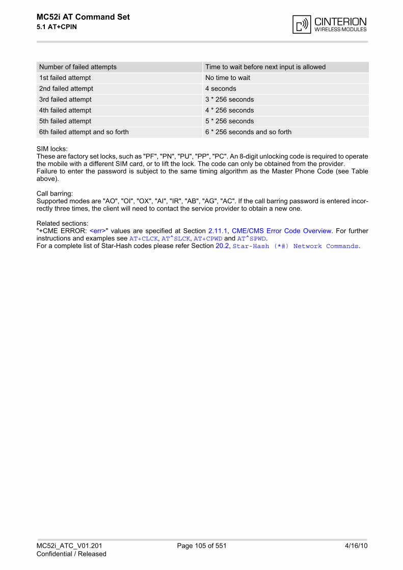
MC52i AT Command Set 5.1 AT+CPIN
MC52i_ATC_V01.201 Page 105 of 551 4/16/10Confidential / Released
SIM locks: These are factory set locks, such as "PF", "PN", "PU", "PP", "PC". An 8-digit unlocking code is required to operatethe mobile with a different SIM card, or to lift the lock. The code can only be obtained from the provider.Failure to enter the password is subject to the same timing algorithm as the Master Phone Code (see Tableabove).
Call barring: Supported modes are "AO", "OI", "OX", "AI", "IR", "AB", "AG", "AC". If the call barring password is entered incor-rectly three times, the client will need to contact the service provider to obtain a new one.
Related sections: "+CME ERROR: <err>" values are specified at Section 2.11.1, CME/CMS Error Code Overview. For furtherinstructions and examples see AT+CLCK, AT^SLCK, AT+CPWD and AT^SPWD. For a complete list of Star-Hash codes please refer Section 20.2, Star-Hash (*#) Network Commands.
Number of failed attempts Time to wait before next input is allowed
1st failed attempt No time to wait
2nd failed attempt 4 seconds
3rd failed attempt 3 * 256 seconds
4th failed attempt 4 * 256 seconds
5th failed attempt 5 * 256 seconds
6th failed attempt and so forth 6 * 256 seconds and so forth
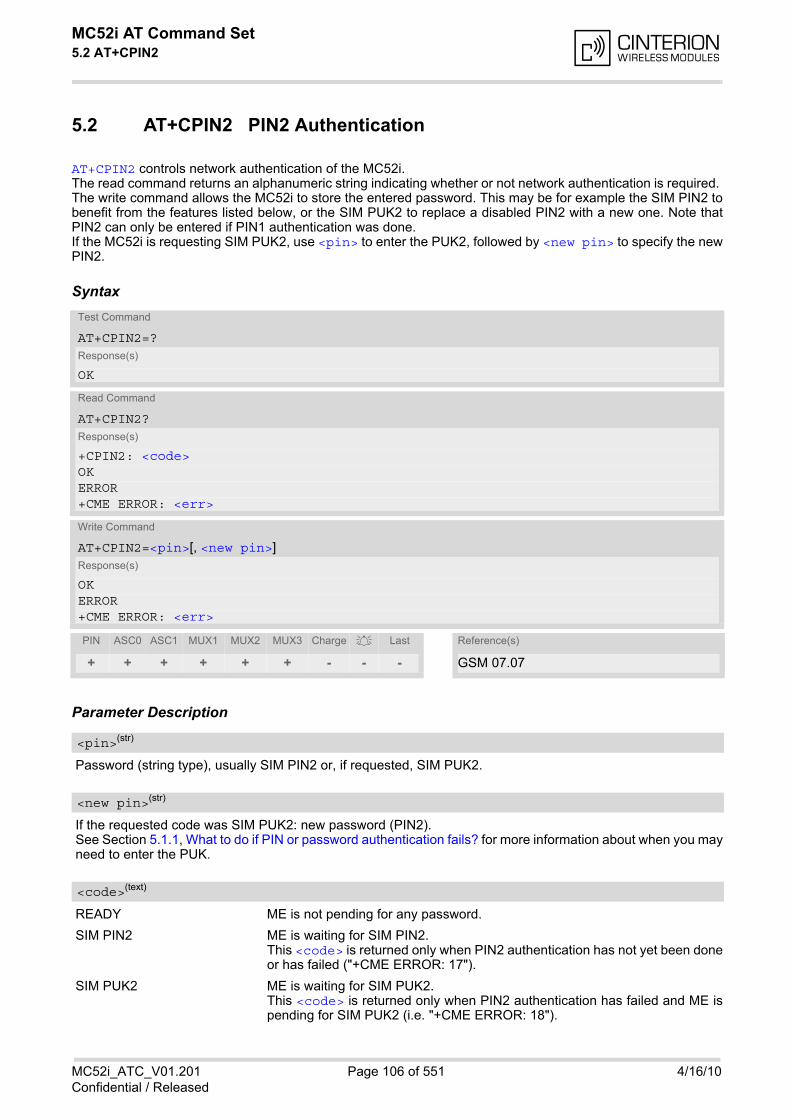
MC52i AT Command Set 5.2 AT+CPIN2
MC52i_ATC_V01.201 Page 106 of 551 4/16/10Confidential / Released
5.2 AT+CPIN2 PIN2 Authentication
AT+CPIN2 controls network authentication of the MC52i. The read command returns an alphanumeric string indicating whether or not network authentication is required. The write command allows the MC52i to store the entered password. This may be for example the SIM PIN2 tobenefit from the features listed below, or the SIM PUK2 to replace a disabled PIN2 with a new one. Note thatPIN2 can only be entered if PIN1 authentication was done. If the MC52i is requesting SIM PUK2, use <pin> to enter the PUK2, followed by <new pin> to specify the newPIN2.
Syntax
Parameter Description
Password (string type), usually SIM PIN2 or, if requested, SIM PUK2.
If the requested code was SIM PUK2: new password (PIN2).See Section 5.1.1, What to do if PIN or password authentication fails? for more information about when you mayneed to enter the PUK.
READY ME is not pending for any password.
SIM PIN2 ME is waiting for SIM PIN2.This <code> is returned only when PIN2 authentication has not yet been doneor has failed ("+CME ERROR: 17").
SIM PUK2 ME is waiting for SIM PUK2.This <code> is returned only when PIN2 authentication has failed and ME ispending for SIM PUK2 (i.e. "+CME ERROR: 18").
Test Command
AT+CPIN2=?Response(s)
OK
Read Command
AT+CPIN2?Response(s)
+CPIN2: <code>OKERROR+CME ERROR: <err>
Write Command
AT+CPIN2=<pin>[, <new pin>]Response(s)
OKERROR+CME ERROR: <err>
PIN ASC0 ASC1 MUX1 MUX2 MUX3 Charge Last Reference(s)
+ + + + + + - - - GSM 07.07
<pin>(str)
<new pin>(str)
<code>(text)
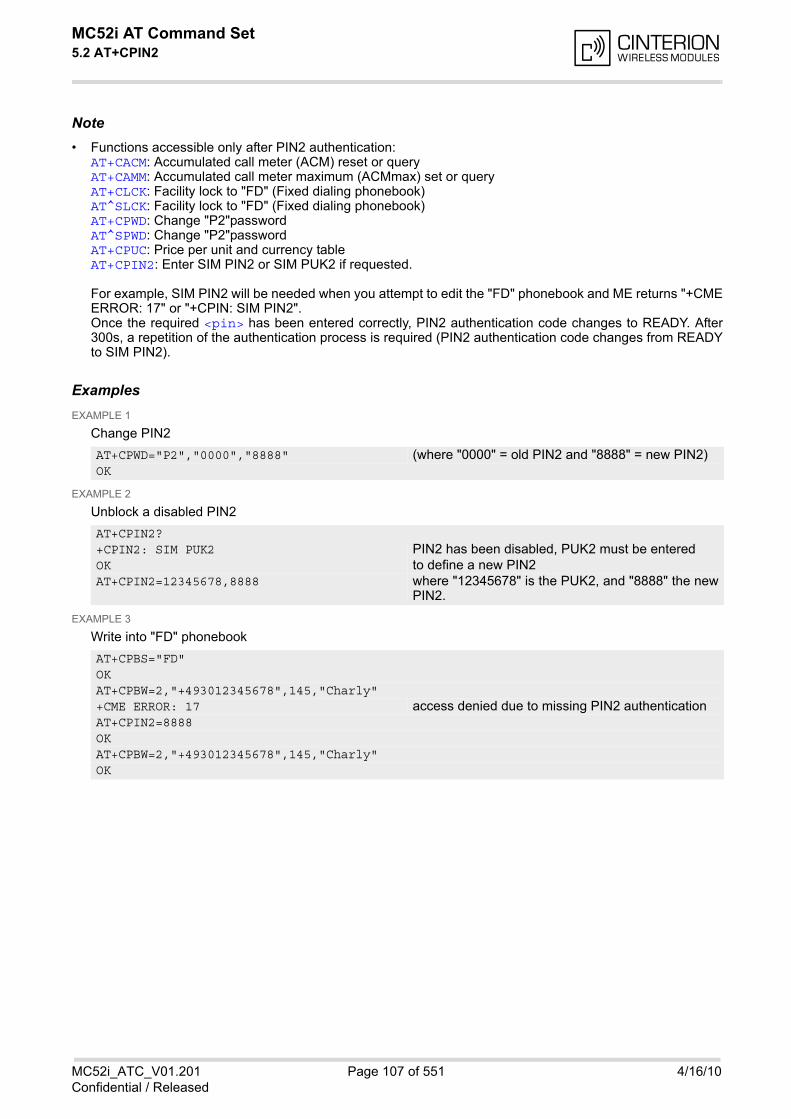
MC52i AT Command Set 5.2 AT+CPIN2
MC52i_ATC_V01.201 Page 107 of 551 4/16/10Confidential / Released
Note• Functions accessible only after PIN2 authentication:
AT+CACM: Accumulated call meter (ACM) reset or queryAT+CAMM: Accumulated call meter maximum (ACMmax) set or queryAT+CLCK: Facility lock to "FD" (Fixed dialing phonebook)AT^SLCK: Facility lock to "FD" (Fixed dialing phonebook)AT+CPWD: Change "P2"passwordAT^SPWD: Change "P2"passwordAT+CPUC: Price per unit and currency tableAT+CPIN2: Enter SIM PIN2 or SIM PUK2 if requested.
For example, SIM PIN2 will be needed when you attempt to edit the "FD" phonebook and ME returns "+CMEERROR: 17" or "+CPIN: SIM PIN2".Once the required <pin> has been entered correctly, PIN2 authentication code changes to READY. After300s, a repetition of the authentication process is required (PIN2 authentication code changes from READYto SIM PIN2).
ExamplesEXAMPLE 1
Change PIN2
EXAMPLE 2
Unblock a disabled PIN2
EXAMPLE 3
Write into "FD" phonebook
AT+CPWD="P2","0000","8888" (where "0000" = old PIN2 and "8888" = new PIN2) OK
AT+CPIN2?+CPIN2: SIM PUK2 PIN2 has been disabled, PUK2 must be entered OK to define a new PIN2 AT+CPIN2=12345678,8888 where "12345678" is the PUK2, and "8888" the new
PIN2.
AT+CPBS="FD"OKAT+CPBW=2,"+493012345678",145,"Charly"+CME ERROR: 17 access denied due to missing PIN2 authentication AT+CPIN2=8888OKAT+CPBW=2,"+493012345678",145,"Charly"OK
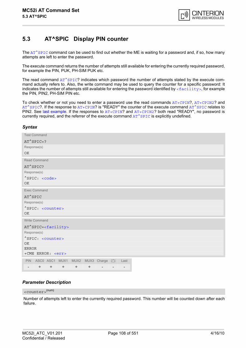
MC52i AT Command Set 5.3 AT^SPIC
MC52i_ATC_V01.201 Page 108 of 551 4/16/10Confidential / Released
5.3 AT^SPIC Display PIN counter
The AT^SPIC command can be used to find out whether the ME is waiting for a password and, if so, how manyattempts are left to enter the password.
The execute command returns the number of attempts still available for entering the currently required password,for example the PIN, PUK, PH-SIM PUK etc.
The read command AT^SPIC? indicates which password the number of attempts stated by the execute com-mand actually refers to. Also, the write command may be used to query the counter for a specific password: Itindicates the number of attempts still available for entering the password identified by <facility>, for examplethe PIN, PIN2, PH-SIM PIN etc.
To check whether or not you need to enter a password use the read commands AT+CPIN?, AT+CPIN2? andAT^SPIC?. If the response to AT+CPIN? is "READY" the counter of the execute command AT^SPIC relates toPIN2. See last example. If the responses to AT+CPIN? and AT+CPIN2? both read "READY", no password iscurrently required, and the referrer of the execute command AT^SPIC is explicitly undefined.
Syntax
Parameter Description
Number of attempts left to enter the currently required password. This number will be counted down after eachfailure.
Test Command
AT^SPIC=?Response(s)
OK
Read Command
AT^SPIC?Response(s)
^SPIC: <code>OK
Exec Command
AT^SPICResponse(s)
^SPIC: <counter>OK
Write Command
AT^SPIC=<facility>Response(s)
^SPIC: <counter>OKERROR+CME ERROR: <err>
PIN ASC0 ASC1 MUX1 MUX2 MUX3 Charge Last
- + + + + + - - -
<counter>(num)
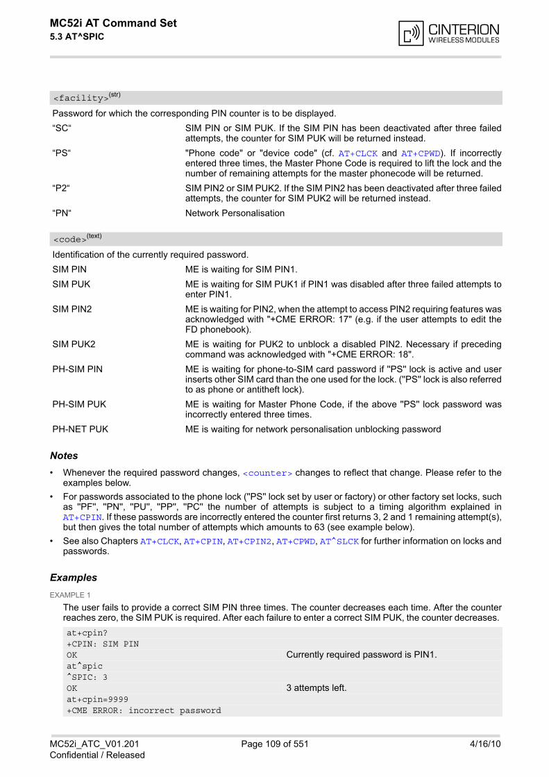
MC52i AT Command Set 5.3 AT^SPIC
MC52i_ATC_V01.201 Page 109 of 551 4/16/10Confidential / Released
Password for which the corresponding PIN counter is to be displayed.
“SC“ SIM PIN or SIM PUK. If the SIM PIN has been deactivated after three failedattempts, the counter for SIM PUK will be returned instead.
“PS“ "Phone code" or "device code" (cf. AT+CLCK and AT+CPWD). If incorrectlyentered three times, the Master Phone Code is required to lift the lock and thenumber of remaining attempts for the master phonecode will be returned.
“P2“ SIM PIN2 or SIM PUK2. If the SIM PIN2 has been deactivated after three failedattempts, the counter for SIM PUK2 will be returned instead.
“PN“ Network Personalisation
Identification of the currently required password.
SIM PIN ME is waiting for SIM PIN1.
SIM PUK ME is waiting for SIM PUK1 if PIN1 was disabled after three failed attempts toenter PIN1.
SIM PIN2 ME is waiting for PIN2, when the attempt to access PIN2 requiring features wasacknowledged with "+CME ERROR: 17" (e.g. if the user attempts to edit theFD phonebook).
SIM PUK2 ME is waiting for PUK2 to unblock a disabled PIN2. Necessary if precedingcommand was acknowledged with "+CME ERROR: 18".
PH-SIM PIN ME is waiting for phone-to-SIM card password if ''PS'' lock is active and userinserts other SIM card than the one used for the lock. (''PS'' lock is also referredto as phone or antitheft lock).
PH-SIM PUK ME is waiting for Master Phone Code, if the above ''PS'' lock password wasincorrectly entered three times.
PH-NET PUK ME is waiting for network personalisation unblocking password
Notes• Whenever the required password changes, <counter> changes to reflect that change. Please refer to the
examples below.
• For passwords associated to the phone lock (''PS'' lock set by user or factory) or other factory set locks, suchas ''PF'', ''PN'', ''PU'', ''PP'', ''PC'' the number of attempts is subject to a timing algorithm explained inAT+CPIN. If these passwords are incorrectly entered the counter first returns 3, 2 and 1 remaining attempt(s),but then gives the total number of attempts which amounts to 63 (see example below).
• See also Chapters AT+CLCK, AT+CPIN, AT+CPIN2, AT+CPWD, AT^SLCK for further information on locks andpasswords.
ExamplesEXAMPLE 1
The user fails to provide a correct SIM PIN three times. The counter decreases each time. After the counterreaches zero, the SIM PUK is required. After each failure to enter a correct SIM PUK, the counter decreases.
<facility>(str)
<code>(text)
at+cpin?+CPIN: SIM PINOK Currently required password is PIN1.at^spic^SPIC: 3OK 3 attempts left.at+cpin=9999+CME ERROR: incorrect password
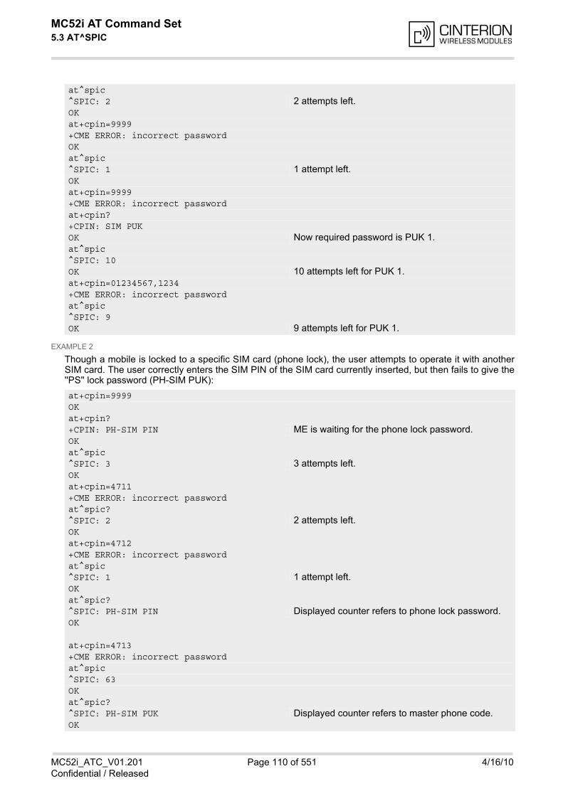
MC52i AT Command Set 5.3 AT^SPIC
MC52i_ATC_V01.201 Page 110 of 551 4/16/10Confidential / Released
EXAMPLE 2
Though a mobile is locked to a specific SIM card (phone lock), the user attempts to operate it with anotherSIM card. The user correctly enters the SIM PIN of the SIM card currently inserted, but then fails to give the''PS'' lock password (PH-SIM PUK):
at^spic^SPIC: 2 2 attempts left.OKat+cpin=9999+CME ERROR: incorrect passwordOKat^spic^SPIC: 1 1 attempt left.OKat+cpin=9999+CME ERROR: incorrect passwordat+cpin?+CPIN: SIM PUK OK Now required password is PUK 1.at^spic^SPIC: 10OK 10 attempts left for PUK 1.at+cpin=01234567,1234+CME ERROR: incorrect passwordat^spic^SPIC: 9OK 9 attempts left for PUK 1.
at+cpin=9999OKat+cpin?+CPIN: PH-SIM PIN ME is waiting for the phone lock password.OKat^spic^SPIC: 3 3 attempts left.OKat+cpin=4711+CME ERROR: incorrect passwordat^spic?^SPIC: 2 2 attempts left.OKat+cpin=4712+CME ERROR: incorrect passwordat^spic^SPIC: 1 1 attempt left.OKat^spic?^SPIC: PH-SIM PIN Displayed counter refers to phone lock password.OK
at+cpin=4713+CME ERROR: incorrect passwordat^spic^SPIC: 63OKat^spic?^SPIC: PH-SIM PUK Displayed counter refers to master phone code.OK
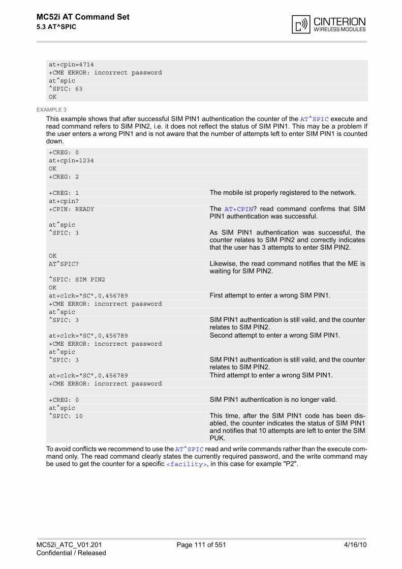
MC52i AT Command Set 5.3 AT^SPIC
MC52i_ATC_V01.201 Page 111 of 551 4/16/10Confidential / Released
EXAMPLE 3
This example shows that after successful SIM PIN1 authentication the counter of the AT^SPIC execute andread command refers to SIM PIN2, i.e. it does not reflect the status of SIM PIN1. This may be a problem ifthe user enters a wrong PIN1 and is not aware that the number of attempts left to enter SIM PIN1 is counteddown.
To avoid conflicts we recommend to use the AT^SPIC read and write commands rather than the execute com-mand only. The read command clearly states the currently required password, and the write command maybe used to get the counter for a specific <facility>, in this case for example "P2".
at+cpin=4714+CME ERROR: incorrect passwordat^spic^SPIC: 63OK
+CREG: 0at+cpin=1234OK+CREG: 2
+CREG: 1 The mobile ist properly registered to the network.at+cpin?+CPIN: READY The AT+CPIN? read command confirms that SIM
PIN1 authentication was successful.at^spic^SPIC: 3 As SIM PIN1 authentication was successful, the
counter relates to SIM PIN2 and correctly indicatesthat the user has 3 attempts to enter SIM PIN2.
OKAT^SPIC? Likewise, the read command notifies that the ME is
waiting for SIM PIN2.^SPIC: SIM PIN2OKat+clck="SC",0,456789 First attempt to enter a wrong SIM PIN1.+CME ERROR: incorrect passwordat^spic^SPIC: 3 SIM PIN1 authentication is still valid, and the counter
relates to SIM PIN2.at+clck="SC",0,456789 Second attempt to enter a wrong SIM PIN1.+CME ERROR: incorrect passwordat^spic^SPIC: 3 SIM PIN1 authentication is still valid, and the counter
relates to SIM PIN2.at+clck="SC",0,456789 Third attempt to enter a wrong SIM PIN1.+CME ERROR: incorrect password
+CREG: 0 SIM PIN1 authentication is no longer valid.at^spic^SPIC: 10 This time, after the SIM PIN1 code has been dis-
abled, the counter indicates the status of SIM PIN1and notifies that 10 attempts are left to enter the SIMPUK.
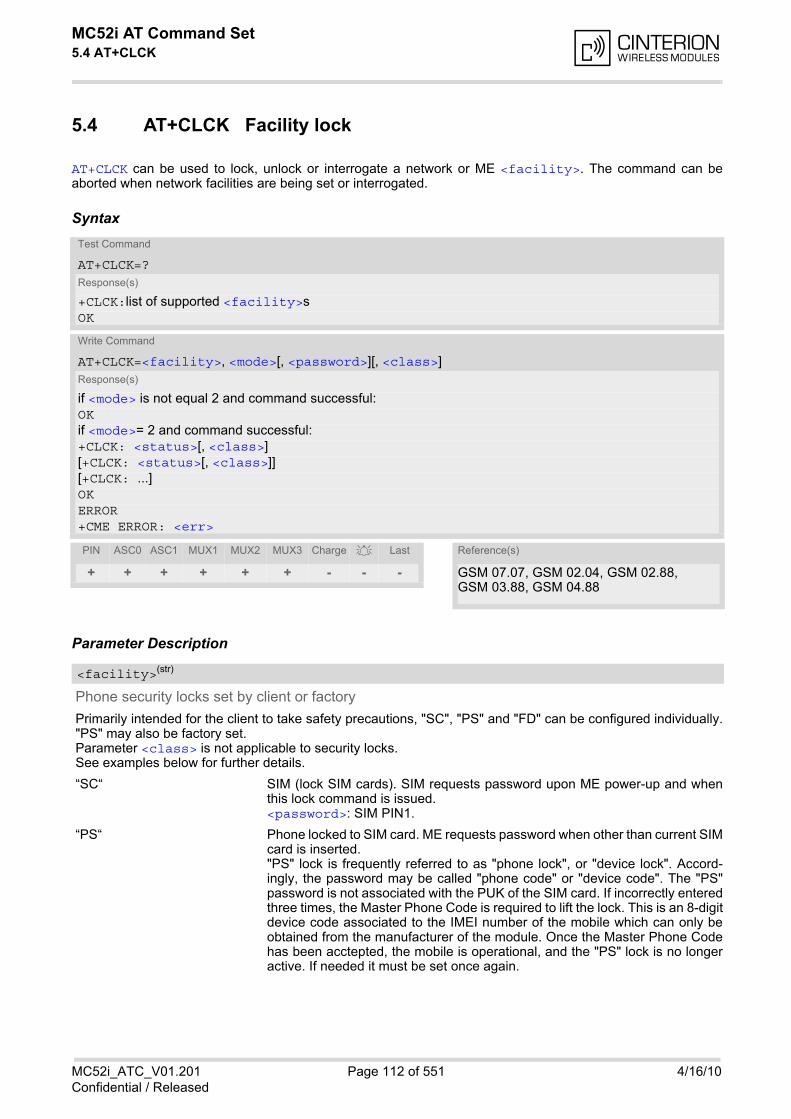
MC52i AT Command Set 5.4 AT+CLCK
MC52i_ATC_V01.201 Page 112 of 551 4/16/10Confidential / Released
5.4 AT+CLCK Facility lock
AT+CLCK can be used to lock, unlock or interrogate a network or ME <facility>. The command can beaborted when network facilities are being set or interrogated.
Syntax
Parameter Description
Phone security locks set by client or factory
Primarily intended for the client to take safety precautions, "SC", "PS" and "FD" can be configured individually."PS" may also be factory set. Parameter <class> is not applicable to security locks.See examples below for further details.
“SC“ SIM (lock SIM cards). SIM requests password upon ME power-up and whenthis lock command is issued.<password>: SIM PIN1.
“PS“ Phone locked to SIM card. ME requests password when other than current SIMcard is inserted."PS" lock is frequently referred to as "phone lock", or "device lock". Accord-ingly, the password may be called "phone code" or "device code". The "PS"password is not associated with the PUK of the SIM card. If incorrectly enteredthree times, the Master Phone Code is required to lift the lock. This is an 8-digitdevice code associated to the IMEI number of the mobile which can only beobtained from the manufacturer of the module. Once the Master Phone Codehas been acctepted, the mobile is operational, and the "PS" lock is no longeractive. If needed it must be set once again.
Test Command
AT+CLCK=?Response(s)
+CLCK:list of supported <facility>s OK
Write Command
AT+CLCK=<facility>, <mode>[, <password>][, <class>]Response(s)
if <mode> is not equal 2 and command successful: OKif <mode>= 2 and command successful: +CLCK: <status>[, <class>][+CLCK: <status>[, <class>]][+CLCK: ...]OKERROR+CME ERROR: <err>
PIN ASC0 ASC1 MUX1 MUX2 MUX3 Charge Last Reference(s)
+ + + + + + - - - GSM 07.07, GSM 02.04, GSM 02.88, GSM 03.88, GSM 04.88
<facility>(str)
MC52i AT Command Set 5.4 AT+CLCK
MC52i_ATC_V01.201 Page 113 of 551 4/16/10Confidential / Released
<password>: User defined password. It is needed before the first use of<facility> "PS" and, therefore, must first be specified with AT+CPWD orAT^SPWD, if it has not been predefined by factory settings. If set by factory (e.g.for a prepaid mobile), the password is supplied by the provider or operator.
“FD“ SIM fixed dialing memory: If the mobile is locked to "FD", only dial strings start-ing with numbers specified in the "FD" memory can be called. The capacity ofthe "FD" phonebook is depending on the SIM card.<password>: SIM PIN 2.Any attempt to dial a number not specified in the "FD" phonebook will bedenied, causing an error result code. The type of result code varies dependingon the type of service:"+CME ERROR: call barred" for voice calls, GPRS connections and *# codesfor Supplementary Services."NO CARRIER" for fax and circuit switched data calls."+CMS ERROR: operation not allowed" for SMS.
Factory defined SIM locks:
Typical examples of factory set SIM locks are prepaid phones or network locks, used to restrict the operation ofa mobile to a specific provider or operator. The client should be aware that each of these lock types can only beunlocked if the associated password is available. For example, a mobile can be locked to accept only SIM cardsfrom the respective provider, or even one single SIM card. Once a different SIM card is inserted the ME willprompt the client to enter a specific code. This is not the PUK of the SIM card, but usually an 8-digit code whichneeds to be requested from the provider.The locks can only be set by the manufacturer and need to be agreed upon between the parties concerned, e.g.provider, operator, distributor etc. on the one side and the manufacturer on the other side. For details contactyour local dealer or Cinterion Wireless Modules GmbH.Parameter <class> is not applicable to SIM locks.<password> and instructions for unlocking must be obtained from the network provider.
“PF“ lock Phone to the very First SIM card
“PN“ Network Personalisation
“PU“ Network subset Personalisation
“PP“ Service Provider Personalisation
“PC“ Corporate Personalisation
Supplementary Service Call Barring:
Supplementary Service "Call Barring" allows to specify conditions under which calls will be disallowed by thenetwork.The availability of the Supplementary Services varies with the network. To benefit from call barring the client willneed to subscribe them, though a limited number of call barring types may be included in the basic tariff pack-age. When you attempt to set a <facility> or <class> which is not provisioned, not yet subscribed to, or not sup-ported by the module, the setting will not take effect regardless of the response returned. The responses in thesecases vary with the network (for example "OK", "+CME ERROR: operation not allowed", "+CME ERROR: oper-ation not supported" etc.). To make sure check the extended error response with AT+CEER and the lock statuswith <mode>=2. <password>: Network password supplied from the provider or operator. Usually there is one password whichapplies to all call barring options. For details contact your provider.
“AO“ BAOC (Bar All Outgoing Calls)
“OI“ BOIC (Bar Outgoing International Calls)
“OX“ BOIC-exHC (Bar Outgoing International Calls except to Home Country)
“AI“ BAIC (Bar All Incoming Calls)
“IR“ BIC-Roam (Bar Incoming Calls when Roaming outside the home country)
“AB“ All Barring services (applicable only for <mode>=0)
MC52i AT Command Set 5.4 AT+CLCK
MC52i_ATC_V01.201 Page 114 of 551 4/16/10Confidential / Released
“AG“ All outGoing barring services (applicable only for <mode>=0)
“AC“ All inComing barring services (applicable only for <mode>=0)
0 unlock
1 lock
2 query status
0 lock is inactive
1 lock is active
Password string used to lock and to unlock a <facility>. Length and authority for passwords depend on the<facility> in question and are therefore listed in the section on parameter <facility>. Passwords can bemodified with AT+CPWD or AT^SPWD.
Integer or sum of integers each representing a class of information, i.e. a bearer service, telecommunication ser-vice or bearer service group as defined in "GSM 02.04".
1 voice
2 class 2 ("data") comprises all those individual data classes between 16 and128, that are supported both by the network and the MS. This means, a settingmade for class 2 applies to all individual data classes (if supported). In addition,you can assign a different setting to a specific class. For example, you can acti-vate Call Forwarding for all data classes, but deactivate it for data class 64,"dedicated packet access".
4 fax
8 SMS
16 data circuit sync
32 data circuit async
64 dedicated packet access
128 dedicated PAD access
1...[7]...255 combination of some of the above classes.For example, the default setting 7 represents the sum of the integers 1, 2 and4 (voice, data and fax).The value 255 covers all classes. If parameter "class" is omitted, the default value 7 is used.
Notes• The AT+CLCK command offers the full range of <class> parameters according to the GSM specifications.
However, when you attempt to use a service option which is not provisioned or not yet subscribed to, the set-ting will not take effect regardless of the response returned.The responses in these cases vary with the network (for example "OK", "Operation not allowed", "Operationnot supported" etc.). To make sure check the extended error response with AT+CEER and the lock status with<mode>=2.
• The command has been implemented with the full set of <class> parameters according to GSM 07.07. Foractual applicability of a desired Call barring service to a specific service or service group (a specific <class>value) please consult table A.1 of GSM 02.04.
<mode>(num)
<status>(num)
<password>(str)
<class>(num)

MC52i AT Command Set 5.4 AT+CLCK
MC52i_ATC_V01.201 Page 115 of 551 4/16/10Confidential / Released
• If an outgoing Fax or Data Call is rejected due to an active ''call barring'' supplementary service, the call willbe terminated with result code NO CARRIER.Under the same conditions, an outgoing Voice call will be terminated with result code NO DIALTONE.
• If an invalid <password> is entered several times in succession, a delay incremented after each failedattempt will increase the time to wait before the input of the <password> is accepted. To avoid blocking theserial interface the running AT+CLCK command is aborted after a short timeout and returns "+CME ERROR:unknown" (+CME ERROR: 100). If then the AT+CLCK command is issued once again execution is deniedwith "+CME ERROR: operation temporary not allowed" (+CME ERROR: 256). For details regarding the delaysee Section 5.1.1, What to do if PIN or password authentication fails?.
• If the user tries to set a lock although it is already active or, the other way round, tries to unlock an inactivelock, the response will be OK, but the <password> will not be checked or verified.
ExamplesEXAMPLE 1
Lock SIM card (<facility>= "SC")
To query the status of the SIM card lock:
AT+CLCK="SC",1,"9999" The "SC" parameter enables or disables the SIM PIN authentication(PIN 1) when you power up the GSM engine
OK SIM card locked. As a result, SIM PIN 1 must be entered to enable MEto register to the GSM network.
AT+CLCK="SC",0,"9999" Unlocks SIM card. OK When powered up, ME registers to the GSM network without requesting
SIM PIN1. Note: Depending on the services offered by the provider, this feature isnot supported by all SIM card types. If so, the command returns ERRORwhen you attempt to unlock the card.
AT+CLCK="SC",2 Query the status of SIM card lock. +CLCK: 1 SIM card is locked. SIM PIN1 must be entered to enable ME to register
to the GSM network. OK
MC52i AT Command Set 5.4 AT+CLCK
MC52i_ATC_V01.201 Page 116 of 551 4/16/10Confidential / Released
EXAMPLE 2
Phone lock (<facility>="PS")
To lock the ME to the currently inserted SIM card, first specify a password for <facility> "PS":
Optionally, if "PS" password was defined before, change existing password:
Then, activate the Phone Lock:
To operate the mobile with the SIM card for which "PS" lock was activated:
To operate the mobile with other SIM card than the one used for the "PS" lock: Enter SIM PIN of present card, followed by "PS" lock password.
To deactivate the Phone Lock:
AT+CPIN? Make sure that PIN1 authentication is valid. OK
AT+CPWD="PS",,"1234" If "PS" lock has not been set before: enter new password. OK
AT+CPWD="PS","1234","3333" To replace existing "PS" password: Enter old and new password. OK
AT+CLCK="PS",1,"3333" Locks the mobile to the current SIM card. OK
AT+CPIN? +CPIN: SIM PIN OK AT+CPIN="9999" OK No additional password is required for operation (SIM recognized by
mobile).
AT+CPIN? +CPIN: SIM PIN OK AT+CPIN="1111" OK PIN authentication accepted. AT+CPIN? +CPIN: PH-SIM PIN "PS" lock password is required. OK AT+CPIN="3333" OK "PS" Lock password has been accepted. ME is fully operational now.
AT+CLCK="PS",0,"3333" Phone Lock password has to be provided again. OK Now the mobile can be used with any SIM card, without the need of the
phone lock password.
MC52i AT Command Set 5.5 AT^SLCK
MC52i_ATC_V01.201 Page 117 of 551 4/16/10Confidential / Released
5.5 AT^SLCK Facility lock
AT^SLCK provides the "Facility lock" function as defined for the GSM 07.07 command AT+CLCK. The commandcan be used to lock, unlock or interrogate a network or ME <facility>.AT^SLCK is, in every respect, identical with AT+CLCK, except that the command syntax and response prefix is"^SLCK" instead of "+CLCK". For further details please refer to AT+CLCK.The command can be aborted when network facilities are being set or interrogated.
SyntaxTest Command
AT^SLCK=?Response(s)
^SLCK:list of supported <facility>s OK
Write Command
AT^SLCK=<facility>, <mode>[, <password>][, <class>]Response(s)
if <mode> is not equal 2 and command successful: OKif <mode>= 2 and command successful: ^SLCK: <status>, <class>[^SLCK: <status>, <class>][^SLCK: ...]OKIf error is related to ME functionality ERROR+CME ERROR: <err>
PIN ASC0 ASC1 MUX1 MUX2 MUX3 Charge Last Reference(s)
+ + + + + + - - - GSM 07.07, GSM 02.04, GSM 02.88, GSM 03.88, GSM 04.88
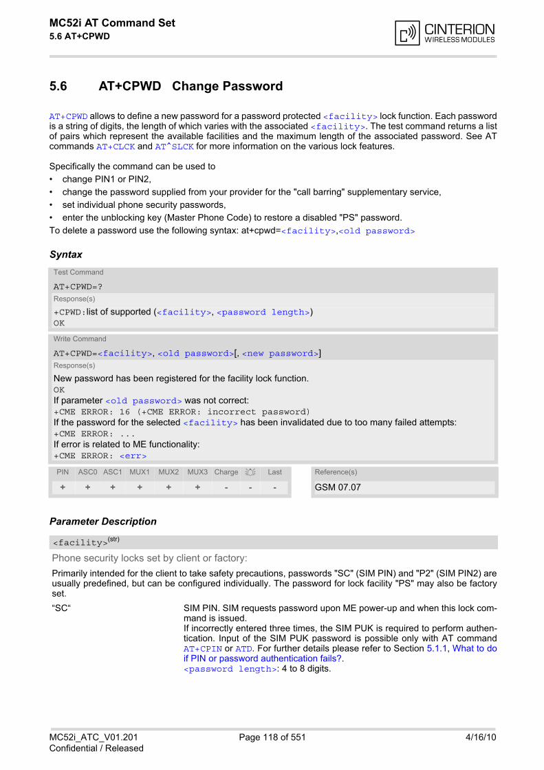
MC52i AT Command Set 5.6 AT+CPWD
MC52i_ATC_V01.201 Page 118 of 551 4/16/10Confidential / Released
5.6 AT+CPWD Change Password
AT+CPWD allows to define a new password for a password protected <facility> lock function. Each passwordis a string of digits, the length of which varies with the associated <facility>. The test command returns a listof pairs which represent the available facilities and the maximum length of the associated password. See ATcommands AT+CLCK and AT^SLCK for more information on the various lock features.
Specifically the command can be used to
• change PIN1 or PIN2,
• change the password supplied from your provider for the "call barring" supplementary service,
• set individual phone security passwords,
• enter the unblocking key (Master Phone Code) to restore a disabled "PS" password.
To delete a password use the following syntax: at+cpwd=<facility>,<old password>
Syntax
Parameter Description
Phone security locks set by client or factory:
Primarily intended for the client to take safety precautions, passwords "SC" (SIM PIN) and "P2" (SIM PIN2) areusually predefined, but can be configured individually. The password for lock facility "PS" may also be factoryset.
“SC“ SIM PIN. SIM requests password upon ME power-up and when this lock com-mand is issued.If incorrectly entered three times, the SIM PUK is required to perform authen-tication. Input of the SIM PUK password is possible only with AT commandAT+CPIN or ATD. For further details please refer to Section 5.1.1, What to doif PIN or password authentication fails?.<password length>: 4 to 8 digits.
Test Command
AT+CPWD=?Response(s)
+CPWD:list of supported (<facility>, <password length>) OK
Write Command
AT+CPWD=<facility>, <old password>[, <new password>]Response(s)
New password has been registered for the facility lock function. OKIf parameter <old password> was not correct:+CME ERROR: 16 (+CME ERROR: incorrect password)If the password for the selected <facility> has been invalidated due to too many failed attempts:+CME ERROR: ...If error is related to ME functionality: +CME ERROR: <err>
PIN ASC0 ASC1 MUX1 MUX2 MUX3 Charge Last Reference(s)
+ + + + + + - - - GSM 07.07
<facility>(str)
MC52i AT Command Set 5.6 AT+CPWD
MC52i_ATC_V01.201 Page 119 of 551 4/16/10Confidential / Released
“PS“ Phone locked to SIM card. ME requests password when other than current SIMcard is inserted."PS" lock is frequently referred to as "phone lock", or "device lock". Accord-ingly, the password may be called "phone code" or "device code". The "PS"password is not associated with the PUK of the SIM card. It must be definedbefore the first use of <facility> "PS" with AT+CLCK. <password length>: 4 digits. If incorrectly entered three times, the Master Phone Code is required to lift thelock. This Unblocking procedure is performed with AT+CPWD using the follow-ing parameters: <facility>="PS", <old password>= Master Phone Code(to be obtained from the module manufacturer), and <new password>= thenew phone code ("PS" password for lock facility), if desired.Mind that successful PIN authentication is a prerequisite for use of AT com-mand AT+CPWD. If Pin authentication has not been completed, input of theMaster Phone code password is possible only with AT command AT+CPIN orATD. For further detail please refer to Section 5.1.1, What to do if PIN or pass-word authentication fails?.Once the Master Phone Code has been acctepted, the mobile is operational,and the "PS" lock is no longer active. If needed it must be set once again withAT+CLCK.
“P2“ SIM PIN 2, e.g. required for authentication with facility lock "FD" (cf. AT+CLCK).If incorrectly entered three times, the SIM PUK 2 is required to perform authen-tication. Input of the SIM PUK 2 password is possible only with AT commandAT+CPIN2 or ATD. For further detail please refer to Section 5.1.1, What to doif PIN or password authentication fails?.<password length>: 4 to 8 digits.
Factory defined SIM locks:
Typical examples of factory set SIM locks are prepaid phones or network locks, used to restrict the operation ofa mobile to a specific provider or operator. The client should be aware that each of these lock types can only beunlocked if the associated password is available. For example, a mobile can be locked to accept only SIM cardsfrom the respective provider, or even one single SIM card. Once a different SIM card is inserted the ME willprompt the client to enter a specific code. This is not the PUK of the SIM card, but usually an 8-digit code whichneeds to be requested from the provider.The locks can only be set by the manufacturer and need to be agreed upon between the parties concerned, e.g.provider, operator, distributor etc. on the one side and the manufacturer on the other side. For details contactyour local dealer or Cinterion Wireless Modules GmbH.
“PF“ Lock Phone to the very First SIM card
“PN“ Network Personalisation
“PU“ Network subset Personalisation
“PP“ Service Provider Personalisation
“PC“ Corporate Personalisation
Supplementary Service Call Barring:
Supplementary Service "Call Barring" allows to specify conditions under which calls will be disallowed by thenetwork.The availability of the Supplementary Services varies with the network. To benefit from call barring the client willneed to subscribe them, though a limited number of call barring types may be included in the basic tariff pack-age. <password length>: The Network Password needs to be supplied from the network provider or network oper-ator. Usually there is one 4 digit password which applies to all call barring options. For details contact your pro-vider.
“AO“ BAOC (Bar All Outgoing Calls)
“OI“ BOIC (Bar Outgoing International Calls)
“OX“ BOIC-exHC (Bar Outgoing International Calls except to Home Country)
“AI“ BAIC (Bar All Incoming Calls)
MC52i AT Command Set 5.6 AT+CPWD
MC52i_ATC_V01.201 Page 120 of 551 4/16/10Confidential / Released
“IR“ BIC-Roam (Bar Incoming Calls when Roaming outside the home country)
“AB“ All Barring services
“AG“ All outGoing barring services
“AC“ All inComing barring services
4...8 Length of password. The range of permitted length for a password depends onthe associated <facility>. It is available from the test command response,or in the description of parameter <facility>.
Password specified for the facility. Parameter <old password> can be ignored if no old password was allocated to the facility. Take into account that a password may have already been set by factory, or that the service is subject to a pass-word issued by the provider. See notes above or contact provider.
New password. Mandatory, if <old password> was an unblocking key (such as the Master Phone Code).
Note• When changing PIN2 (<facility>="P2") it is recommended to check the new state of PIN2 by using the
AT+CPIN2 command.
ExamplesEXAMPLE 1
To change PIN2
EXAMPLE 2
To set password used to enable or disable barring of all outgoing calls:
EXAMPLE 3
Handling of the "PS" lock password
<password length>(num)
<old password>(str)
<new password>(str)
AT+CPWD="P2","0000","8888" (where "0000" = old PIN2 and "8888" = new PIN2) OK PIN2 Password has been changed to "8888"
AT+CPWD="AO","0000","3333" Requests the network to change the password forsupplementary service "call barring".
OK Usually this request will affect all barring services,even though the request is issued for SupplementaryService BAOC ("Barring of all outgoing calls") only.Refer to the respective network provider for detail.
AT+CMEE=2 Enable text output of CME Error information AT+CPWD="PS","1111","2222" (where "1111" = old password and "2222" = new
password) OK Password for facility "PS" is now "2222" AT+CPWD="PS","1111","2222" Repeat command to provoke error "incorrect pass-
word" +CME ERROR: incorrect password ("1111" is no longer the correct password)
MC52i AT Command Set 5.6 AT+CPWD
MC52i_ATC_V01.201 Page 121 of 551 4/16/10Confidential / Released
EXAMPLE 4
To specify a new "PS" lock password, after the old password was disabled (e.g. after three failed attempts tochange the "PS" password): use the master phone code. CAUTION: THIS TEST SHOULD BE PERFORMED ONLY IF THE CORRECT MASTER PHONE CODE FORTHE INDIVIDUAL ME USED IS DEFINITELY AVAILABLE! Otherwise the module used will be rendered use-less until the correct master phone code is entered!:
Alternatively, without giving a new password:
AT+CPWD="PS","12345678","1111" where 12345678 is the Master Phone Code and1111 is the new password. You may also use <newpassword> to restore the former disabled pass-word.
OK
AT+CPWD="PS","12345678" (where 12345678 is the Master Phone Code). Deac-tivates the present phone lock.
OK
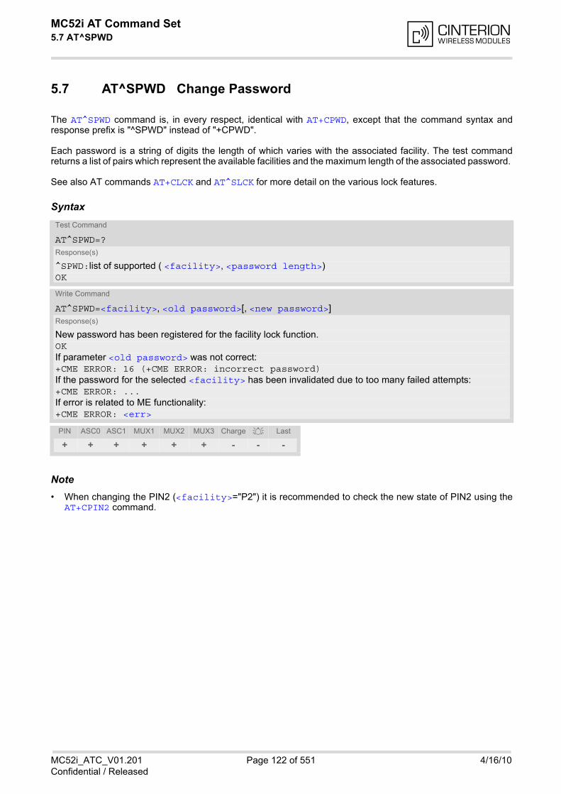
MC52i AT Command Set 5.7 AT^SPWD
MC52i_ATC_V01.201 Page 122 of 551 4/16/10Confidential / Released
5.7 AT^SPWD Change Password
The AT^SPWD command is, in every respect, identical with AT+CPWD, except that the command syntax andresponse prefix is "^SPWD" instead of "+CPWD".
Each password is a string of digits the length of which varies with the associated facility. The test commandreturns a list of pairs which represent the available facilities and the maximum length of the associated password.
See also AT commands AT+CLCK and AT^SLCK for more detail on the various lock features.
Syntax
Note• When changing the PIN2 (<facility>="P2") it is recommended to check the new state of PIN2 using the
AT+CPIN2 command.
Test Command
AT^SPWD=?Response(s)
^SPWD:list of supported ( <facility>, <password length>) OK
Write Command
AT^SPWD=<facility>, <old password>[, <new password>]Response(s)
New password has been registered for the facility lock function. OKIf parameter <old password> was not correct:+CME ERROR: 16 (+CME ERROR: incorrect password)If the password for the selected <facility> has been invalidated due to too many failed attempts:+CME ERROR: ...If error is related to ME functionality: +CME ERROR: <err>
PIN ASC0 ASC1 MUX1 MUX2 MUX3 Charge Last
+ + + + + + - - -
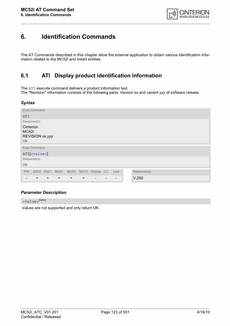
MC52i AT Command Set 6. Identification Commands
MC52i_ATC_V01.201 Page 123 of 551 4/16/10Confidential / Released
6. Identification Commands
The AT Commands described in this chapter allow the external application to obtain various identification infor-mation related to the MC52i and linked entities.
6.1 ATI Display product identification information
The ATI execute command delivers a product information text.The "Revision" information consists of the following parts: Version xx and variant yyy of software release.
Syntax
Parameter Description
Values are not supported and only return OK.
Exec Command
ATIResponse(s)
CinterionMC52iREVISION xx.yyyOK
Exec Command
ATI[<value>]Response(s)
OK
PIN ASC0 ASC1 MUX1 MUX2 MUX3 Charge Last Reference(s)
- + + + + + - - - V.250
<value>(num)

MC52i AT Command Set 6.2 AT+CGMI
MC52i_ATC_V01.201 Page 124 of 551 4/16/10Confidential / Released
6.2 AT+CGMI Request manufacturer identification
AT+CGMI returns a manufacturer identification text. See also: AT+GMI.
Syntax
6.3 AT+GMI Request manufacturer identification
AT+GMI returns a manufacturer identification text. See also: AT+CGMI.
Syntax
Test Command
AT+CGMI=?Response(s)
OK
Exec Command
AT+CGMIResponse(s)
CinterionOK
PIN ASC0 ASC1 MUX1 MUX2 MUX3 Charge Last Reference(s)
- + + + + + - - - GSM 07.07
Test Command
AT+GMI=?Response(s)
OK
Exec Command
AT+GMIResponse(s)
CinterionOK
PIN ASC0 ASC1 MUX1 MUX2 MUX3 Charge Last Reference(s)
- + + + + + - - - V.250

MC52i AT Command Set 6.4 AT+CGMM
MC52i_ATC_V01.201 Page 125 of 551 4/16/10Confidential / Released
6.4 AT+CGMM Request model identification
AT+CGMM returns a product model identification text. Command is identical with AT+GMM.
Syntax
6.5 AT+GMM Request model identification
AT+GMM returns a product model identification text. Command is identical with AT+CGMM.
Syntax
Test Command
AT+CGMM=?Response(s)
OK
Exec Command
AT+CGMMResponse(s)
MC52iOK
PIN ASC0 ASC1 MUX1 MUX2 MUX3 Charge Last Reference(s)
- + + + + + - - - GSM 07.07
Test Command
AT+GMM=?Response(s)
OK
Exec Command
AT+GMMResponse(s)
MC52iOK
PIN ASC0 ASC1 MUX1 MUX2 MUX3 Charge Last Reference(s)
- + + + + + - - - V.250
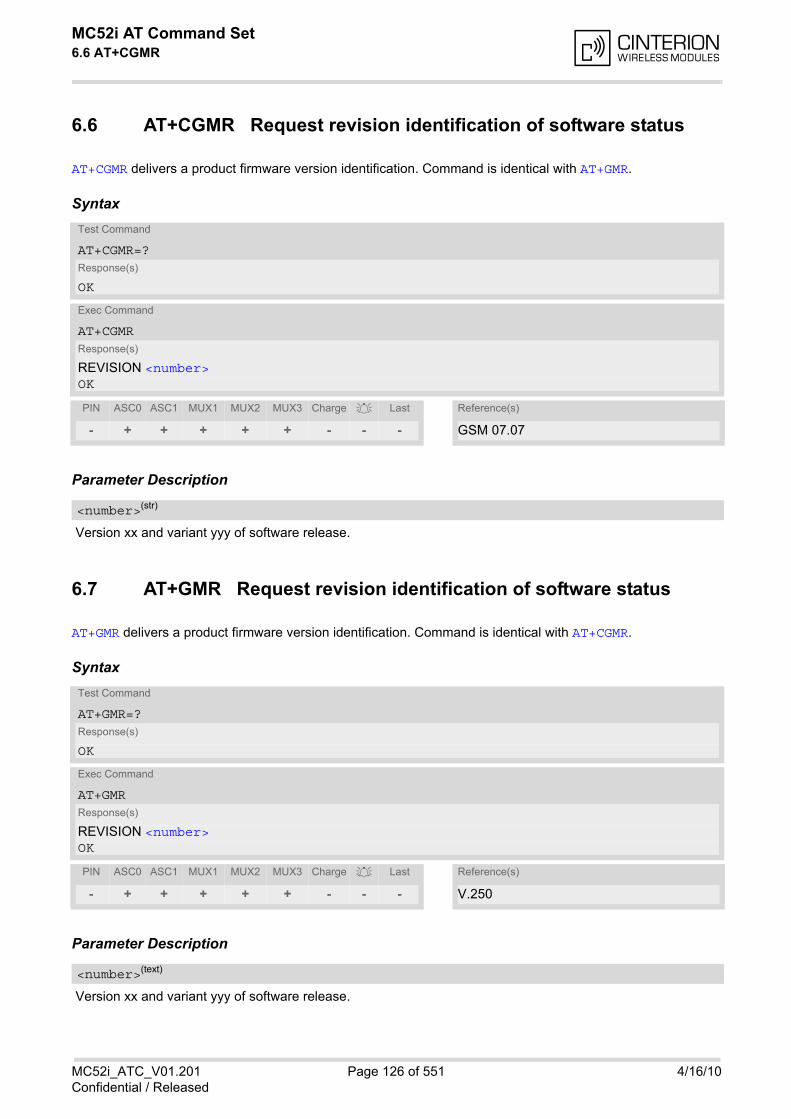
MC52i AT Command Set 6.6 AT+CGMR
MC52i_ATC_V01.201 Page 126 of 551 4/16/10Confidential / Released
6.6 AT+CGMR Request revision identification of software status
AT+CGMR delivers a product firmware version identification. Command is identical with AT+GMR.
Syntax
Parameter Description
Version xx and variant yyy of software release.
6.7 AT+GMR Request revision identification of software status
AT+GMR delivers a product firmware version identification. Command is identical with AT+CGMR.
Syntax
Parameter Description
Version xx and variant yyy of software release.
Test Command
AT+CGMR=?Response(s)
OK
Exec Command
AT+CGMRResponse(s)
REVISION <number>OK
PIN ASC0 ASC1 MUX1 MUX2 MUX3 Charge Last Reference(s)
- + + + + + - - - GSM 07.07
<number>(str)
Test Command
AT+GMR=?Response(s)
OK
Exec Command
AT+GMRResponse(s)
REVISION <number>OK
PIN ASC0 ASC1 MUX1 MUX2 MUX3 Charge Last Reference(s)
- + + + + + - - - V.250
<number>(text)

MC52i AT Command Set 6.8 AT+CGSN
MC52i_ATC_V01.201 Page 127 of 551 4/16/10Confidential / Released
6.8 AT+CGSN Request International Mobile Equipment Identity (IMEI)
AT+CGSN delivers the International Mobile Equipment Identity (IMEI). Command is identical with: AT+GSN.
Syntax
Parameter Description
International Mobile Equipment Identity (IMEI) used to identify a GSM mobile equipment to the GSM network
6.9 AT+GSN Request International Mobile Equipment Identity (IMEI)
AT+GSN delivers the International Mobile Equipment Identity (IMEI). Command is identical with AT+CGSN
Syntax
Parameter Description
International Mobile Equipment Identity (IMEI) used to identify a GSM mobile equipment to the GSM network.
Test Command
AT+CGSN=?Response(s)
OK
Exec Command
AT+CGSNResponse(s)
<sn>OK
PIN ASC0 ASC1 MUX1 MUX2 MUX3 Charge Last Reference(s)
- + + + + + - - - GSM 07.07
<sn>(str)
Test Command
AT+GSN=?Response(s)
OK
Exec Command
AT+GSNResponse(s)
<sn>OK
PIN ASC0 ASC1 MUX1 MUX2 MUX3 Charge Last Reference(s)
- + + + + + - - - V.250
<sn>(str)
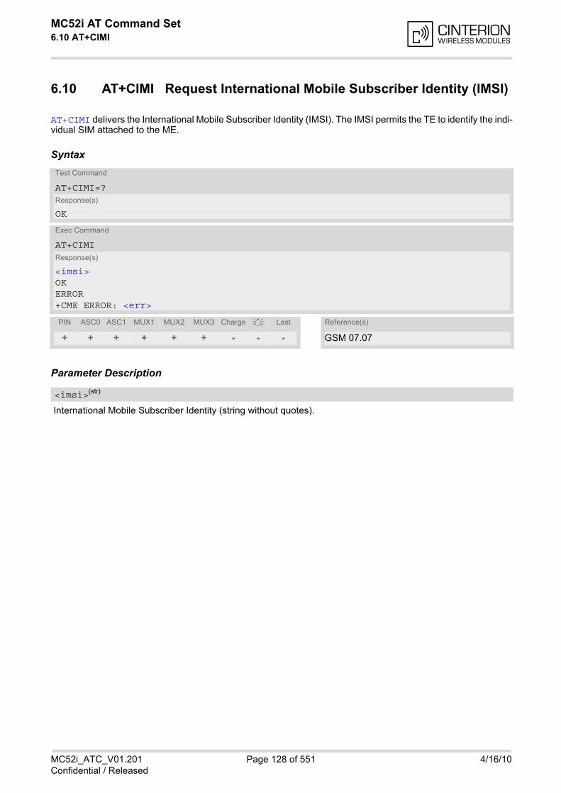
MC52i AT Command Set 6.10 AT+CIMI
MC52i_ATC_V01.201 Page 128 of 551 4/16/10Confidential / Released
6.10 AT+CIMI Request International Mobile Subscriber Identity (IMSI)
AT+CIMI delivers the International Mobile Subscriber Identity (IMSI). The IMSI permits the TE to identify the indi-vidual SIM attached to the ME.
Syntax
Parameter Description
International Mobile Subscriber Identity (string without quotes).
Test Command
AT+CIMI=?Response(s)
OK
Exec Command
AT+CIMIResponse(s)
<imsi>OKERROR+CME ERROR: <err>
PIN ASC0 ASC1 MUX1 MUX2 MUX3 Charge Last Reference(s)
+ + + + + + - - - GSM 07.07
<imsi>(str)
MC52i AT Command Set 7. Call related Commands
MC52i_ATC_V01.201 Page 129 of 551 4/16/10Confidential / Released
7. Call related Commands
The AT Commands described in this chapter are related to Mobile Originated (MOC, i.e. outgoing) Calls andMobile Terminated (MTC, i.e. incoming) Calls.
7.1 Call Status Information
For Circuit switched calls, including voice, fax and data calls, call status information is available with URC"+CIEV: call" (configurable via AT commands AT+CIND and AT+CMER) or - in more detail - from the list of currentcalls. This list can be displayed on request via at commands AT+CLCC and AT^SLCC. It can also be issued bythe ME in the form of an unsolicited result code "^SLCC" if configured with AT^SLCC and AT+CMER.URC "+CIEV: call" and URC "^SLCC" can be configured using AT command AT^SCFG. An overview of the pos-sible configurations and their consequences for the availability of call status information will be given here.
Generally speaking, the call status values recognized by the ME are as follows:
• active
• held
• dialing (MOC)
• alerting (MOC)
• incoming (MTC)
• waiting (MTC)
• terminating: The call is not active anymore, but inband information is still available.
• dropped: The call has been suspended by the network, but may be resumed later.
The values "terminating" and "dropped" are not standardized for AT command AT+CLCC, and therefore onlyavailable for command AT^SLCC. A call in any of these two states will not appear in the list of current calls asdisplayed with AT+CLCC. A call that is not recognized by the ME is considered to be in "unknown" state.Some networks may schedule a traffic channel for a call that is not yet in the "active" state. This is reflected inparameter <traffic channel assigned> of AT command AT^SLCC and the corresponding URC.Depending on the value of AT^SCFG setting <succ>, Indicator "+CIEV" will be issued (if configured withAT+CIND and AT+CMER)
• when a state transition ends in state "active" or in state "unknown" (if AT^SCFG setting <succ>=''restricted'').
• when any state transition (including transitions beginning or ending in state "unknown") occurs in the list ofactive calls, or when a traffic channel is established(if AT^SCFG setting <succ>=''verbose'').
The indicator value for indicator "+CIEV: call" will be "1" if at least one call is in states "held" or "active", and "0"otherwise.
Depending on the value of AT^SCFG setting <sucs>, Indicator "^SLCC" will be issued (if configured with writecommand AT^SLCC and AT+CMER)
• when a state transition ends in state "active" or in state "unknown" (if AT^SCFG setting <sucs>="restricted")
• when any state transition (including transitions beginning or ending in state "unknown") occurs in the list ofactive calls, or when a voice channel is established (if AT^SCFG setting <sucs>="verbose").
Due to compatibility considerations, the powerup default for AT^SCFG setting <succ> is "restricted", offeringcompatibility to the standard behaviour of indicator "+CIEV: call", while the default for setting <sucs> is "ver-bose".In order to see the URCs, event reporting for both indicators must be explicitly configured with the appropriateAT commands.
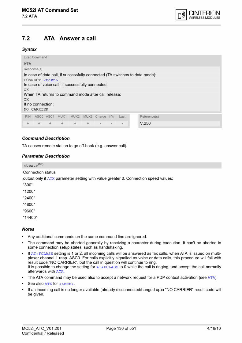
MC52i AT Command Set 7.2 ATA
MC52i_ATC_V01.201 Page 130 of 551 4/16/10Confidential / Released
7.2 ATA Answer a call
Syntax
Command DescriptionTA causes remote station to go off-hook (e.g. answer call).
Parameter Description
Connection status
output only if ATX parameter setting with value greater 0. Connection speed values:
“300“
“1200“
“2400“
“4800“
“9600“
“14400“
Notes• Any additional commands on the same command line are ignored.
• The command may be aborted generally by receiving a character during execution. It can't be aborted insome connection setup states, such as handshaking.
• If AT+FCLASS setting is 1 or 2, all incoming calls will be answered as fax calls, when ATA is issued on multi-plexer channel 1 resp. ASC0. For calls explicitly signalled as voice or data calls, this procedure will fail withresult code "NO CARRIER", but the call in question will continue to ring.It is possible to change the setting for AT+FCLASS to 0 while the call is ringing, and accept the call normallyafterwards with ATA.
• The ATA command may be used also to accept a network request for a PDP context activation (see ATA).
• See also ATX for <text>.
• If an incoming call is no longer available (already disconnected/hanged up)a "NO CARRIER" result code willbe given.
Exec Command
ATAResponse(s)
In case of data call, if successfully connected (TA switches to data mode):CONNECT <text>In case of voice call, if successfully connected:OKWhen TA returns to command mode after call release:OKIf no connection:NO CARRIER
PIN ASC0 ASC1 MUX1 MUX2 MUX3 Charge Last Reference(s)
+ + + + + + - - - V.250
<text>(str)
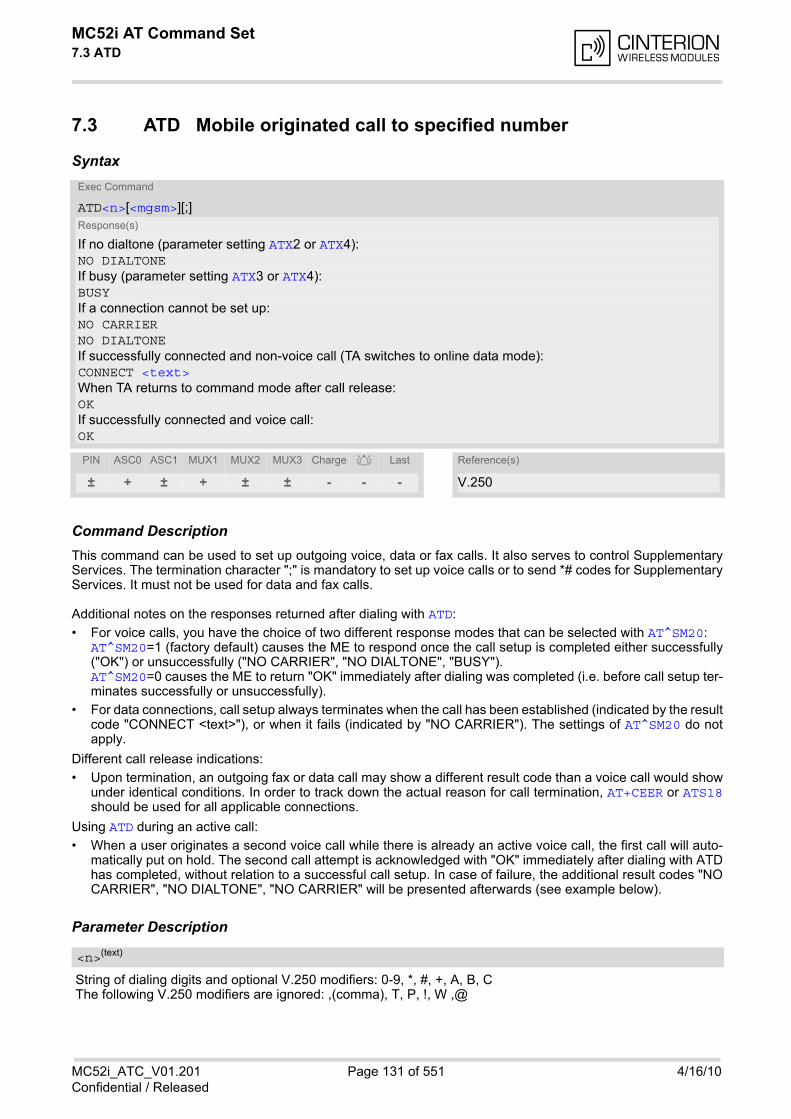
MC52i AT Command Set 7.3 ATD
MC52i_ATC_V01.201 Page 131 of 551 4/16/10Confidential / Released
7.3 ATD Mobile originated call to specified number
Syntax
Command DescriptionThis command can be used to set up outgoing voice, data or fax calls. It also serves to control SupplementaryServices. The termination character ";" is mandatory to set up voice calls or to send *# codes for SupplementaryServices. It must not be used for data and fax calls.
Additional notes on the responses returned after dialing with ATD:
• For voice calls, you have the choice of two different response modes that can be selected with AT^SM20:AT^SM20=1 (factory default) causes the ME to respond once the call setup is completed either successfully("OK") or unsuccessfully ("NO CARRIER", "NO DIALTONE", "BUSY"). AT^SM20=0 causes the ME to return "OK" immediately after dialing was completed (i.e. before call setup ter-minates successfully or unsuccessfully).
• For data connections, call setup always terminates when the call has been established (indicated by the resultcode "CONNECT <text>"), or when it fails (indicated by "NO CARRIER"). The settings of AT^SM20 do notapply.
Different call release indications:
• Upon termination, an outgoing fax or data call may show a different result code than a voice call would showunder identical conditions. In order to track down the actual reason for call termination, AT+CEER or ATS18should be used for all applicable connections.
Using ATD during an active call:
• When a user originates a second voice call while there is already an active voice call, the first call will auto-matically put on hold. The second call attempt is acknowledged with "OK" immediately after dialing with ATDhas completed, without relation to a successful call setup. In case of failure, the additional result codes "NOCARRIER", "NO DIALTONE", "NO CARRIER" will be presented afterwards (see example below).
Parameter Description
String of dialing digits and optional V.250 modifiers: 0-9, *, #, +, A, B, CThe following V.250 modifiers are ignored: ,(comma), T, P, !, W ,@
Exec Command
ATD<n>[<mgsm>][;]Response(s)
If no dialtone (parameter setting ATX2 or ATX4):NO DIALTONEIf busy (parameter setting ATX3 or ATX4):BUSYIf a connection cannot be set up:NO CARRIERNO DIALTONEIf successfully connected and non-voice call (TA switches to online data mode):CONNECT <text>When TA returns to command mode after call release:OKIf successfully connected and voice call:OK
PIN ASC0 ASC1 MUX1 MUX2 MUX3 Charge Last Reference(s)
± + ± + ± ± - - - V.250
<n>(text)

MC52i AT Command Set 7.3 ATD
MC52i_ATC_V01.201 Page 132 of 551 4/16/10Confidential / Released
String of GSM modifiers:I Activates CLIR (disables presentation of own phone number to called party)i Deactivates CLIR (enables presentation of own phone number to called party)G Activate Closed User Group explicit invocation for this call only.g Deactivate Closed User Group explicit invocation for this call only.
Notes• The command may be aborted generally when receiving a character during execution. It cannot be aborted
in some connection setup states, such as handshaking.
• Parameter "I" and "i" only if no *#-code is within the dial string.
• <mgsm> is not supported for data calls.
• <n> is default for last number that can be dialled by ATDL.
• See also ATX for <text>.
• If ATD is used with a USSD command (e.g. ATD*100#;) an AT+CUSD=1 is executed implicitly (see AT+CUSD).
• Parameter 'G' or 'g' will be ignored if Closed User Group was already activated, respectively deactivated withAT+CCUG command before. Call by call invocation of CUG uses the settings provisioned by the provider or,if available, the settings of the parameters <index> and <info> made with AT+CCUG.
• The ME is equipped with a "Blacklist" function according to GSM02.07 Annex A. The handling of failed callattempts follows the timing restrictions specified there. When the maximum number of failed call attempts isreached the number will be blacklisted. Call attempts to blacklisted numbers will be barred by the ME and notsignalled to the network.An attempt to start a voice call to a barred phone number is denied with a "+CME ERROR: call barred".An attempt to start a data or fax call to a barred phone number is denied with "NO CARRIER".According to GSM02.07 Annex A, the barred numbers will be removed from the blacklist after a call attemptwas successful or after module restart.
• Emergency calls: MC52i supports 112, 911 and 08 (standardized GSM emergency numbers, usable with or without SIM).
• When using the command on the second serial interface please see also Section 1.9.
Example
The following example shows the call setup procedure when a call is already active and a second call attemptfails because the line of the called party is busy:
<mgsm>(str)
ATD03012345678; Dialing out the first party's number.OK The first call is established.ATD03022222222; The number of the second party is dialed.OK The response "OK" is issued immediately though no call is established
(same behavior as is you had chosen AT^SM20=0.)BUSY Line of the second called party is busy.
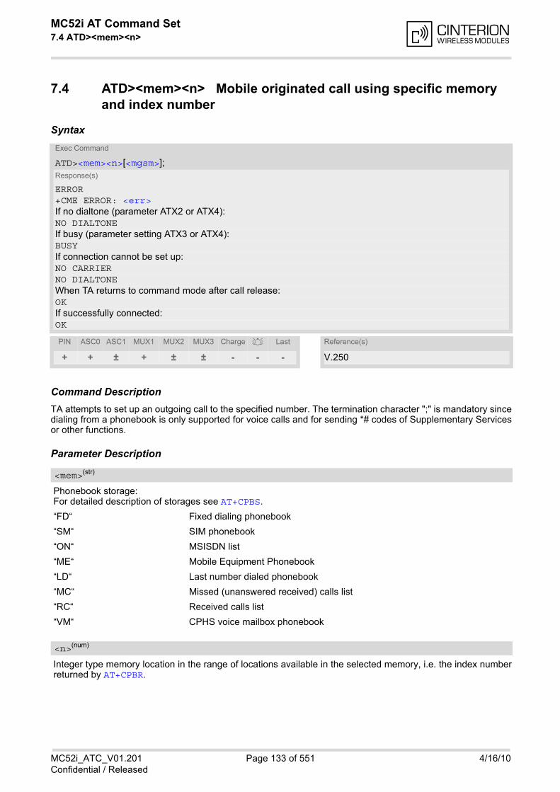
MC52i AT Command Set 7.4 ATD><mem><n>
MC52i_ATC_V01.201 Page 133 of 551 4/16/10Confidential / Released
7.4 ATD><mem><n> Mobile originated call using specific memory and index number
Syntax
Command DescriptionTA attempts to set up an outgoing call to the specified number. The termination character ";" is mandatory sincedialing from a phonebook is only supported for voice calls and for sending *# codes of Supplementary Servicesor other functions.
Parameter Description
Phonebook storage:For detailed description of storages see AT+CPBS.
“FD“ Fixed dialing phonebook
“SM“ SIM phonebook
“ON“ MSISDN list
“ME“ Mobile Equipment Phonebook
“LD“ Last number dialed phonebook
“MC“ Missed (unanswered received) calls list
“RC“ Received calls list
“VM“ CPHS voice mailbox phonebook
Integer type memory location in the range of locations available in the selected memory, i.e. the index numberreturned by AT+CPBR.
Exec Command
ATD><mem><n>[<mgsm>];Response(s)
ERROR+CME ERROR: <err>If no dialtone (parameter ATX2 or ATX4):NO DIALTONEIf busy (parameter setting ATX3 or ATX4):BUSYIf connection cannot be set up:NO CARRIERNO DIALTONEWhen TA returns to command mode after call release:OKIf successfully connected:OK
PIN ASC0 ASC1 MUX1 MUX2 MUX3 Charge Last Reference(s)
+ + ± + ± ± - - - V.250
<mem>(str)
<n>(num)
MC52i AT Command Set 7.4 ATD><mem><n>
MC52i_ATC_V01.201 Page 134 of 551 4/16/10Confidential / Released
String of GSM modifiers:I Activates CLIR (disables presentation of own phone number to called party)i Deactivates CLIR (enables presentation of own phone number to called party)
Notes• This command may be aborted generally by receiving a character during execution. Abortion is not possible
during some states of connection setup such as handshaking.
• There is no <mem> for emergency call ("EN").
• The command is not applicable to data calls. Any attempt to dial a data call number from <mem> causes theresult code "NO CARRIER" to appear.
• Parameter <mgsm> only if no *# code is within the dialing string.
• See ATX for setting result code and call monitoring parameters.
ExamplesEXAMPLE 1
To query the location number of the phonebook entry:
TA returns the entries available in the active phonebook.
EXAMPLE 2
To dial a number from the SIM phonebook, for example the number stored to location 15:
EXAMPLE 3
To dial a phone number stored in the last dial memory on the SIM card:
<mgsm>(str)
AT+CPBR=1,xx
ATD>"SM"15;OK
ATD>"LD"9;OK
MC52i AT Command Set 7.5 ATD><n>
MC52i_ATC_V01.201 Page 135 of 551 4/16/10Confidential / Released
7.5 ATD><n> Mobile originated call from active memory using index number
Syntax
Command DescriptionTA attempts to set up an outgoing call to the stored number. The termination character ";" is mandatory sincedialing from a phonebook is only supported for voice calls and for sending *# codes of Supplementary Servicesor other functions.
Parameter Description
Integer type memory location in the range of locations available in the selected memory, i.e. the index numberreturned by AT+CPBR.
String of GSM modifiers:I Activates CLIR (disables presentation of own phone number to called party)i Deactivates CLIR (enables presentation of own phone number to called party)
Notes• This command may be aborted generally by receiving a character during execution. Abortion is not possible
during some states of connection setup such as handshaking.
• The command is not applicable to data calls. Any attempt to dial a data call number from <n> causes theresult code "NO CARRIER" to appear.
• Parameter <mgsm> only if no *# code is within the dialing string.
Exec Command
ATD><n>[<mgsm>];Response(s)
ERROR+CME ERROR: <err>If no dialtone (parameter ATX2 or ATX4):NO DIALTONEIf busy (parameter setting ATX3 or ATX4):BUSYIf connection cannot be set up:NO CARRIERNO DIALTONEWhen TA returns to command mode after call release:OKIf successfully connected:OK
PIN ASC0 ASC1 MUX1 MUX2 MUX3 Charge Last Reference(s)
+ + ± + ± ± - - - V.250
<n>(num)
<mgsm>(str)
MC52i AT Command Set 7.6 ATD><str>
MC52i_ATC_V01.201 Page 136 of 551 4/16/10Confidential / Released
7.6 ATD><str> Mobile originated call from active memory using cor-responding field
Syntax
Command DescriptionThis command searches the active phonebook for a given string <str> and dials the assigned phone number.The termination character ";" is mandatory since dialing from a phonebook is only supported for voice calls andfor sending *# codes of Supplementary Services or other functions.
Parameter Description
String type value ("x"), which should equal an alphanumeric field in at least one phonebook entry in the searchedmemories; used character set should be the one selected with AT+CSCS. <str> can contain escape sequencesas described in chapter "Supported character sets".<str> must be wrapped in quotation marks (""), if escape sequences or parameter <mgsm> are used or if thealphanumeric strings contains a blank. If not, quotation marks are optional.If AT+CSCS is set to "UCS2", with respect to the coding of UCS2-characters only phonebook entries that containan alphanumeric string with a size less than the half of the parameter <tlength> from AT+CPBW can be dialed.
String of GSM modifiers:I Activates CLIR (disables presentation of own phone number to called party)i Deactivates CLIR (enables presentation of own phone number to called party)
Notes• This command may be aborted generally by receiving a character during execution. Abortion is not possible
during some states of connection setup such as handshaking.
• The command is not applicable to data calls. Any attempt to dial <str> without semicolon ";" causes theresult code "NO CARRIER" to appear.
• Parameter <mgsm> only if no *# code is within the dialing string.
Exec Command
ATD><str>[<mgsm>];Response(s)
ERROR+CME ERROR: <err>If no dialtone (parameter ATX2 or ATX4):NO DIALTONEIf busy (parameter setting ATX3 or ATX4):BUSYIf connectioncannot be set up:NO CARRIERNO DIALTONEWhen TA returns to command mode after call release:OKIf successfully connected:OK
PIN ASC0 ASC1 MUX1 MUX2 MUX3 Charge Last Reference(s)
+ + ± + ± ± - - - V.250
<str>(str)(+CSCS)
<mgsm>(str)
MC52i AT Command Set 7.7 ATDI
MC52i_ATC_V01.201 Page 137 of 551 4/16/10Confidential / Released
7.7 ATDI Mobile originated call to ISDN number
Syntax
Command DescriptionTA attempts to set up an outgoing call to ISDN number. The termination character ";" is mandatory to set up voicecalls or to send *# codes for Supplementary Services. It must not be used for data and fax calls.
Parameter Description
ISDN numberString with maximum length of 20 characters. Allowed characters: +, 0-9, A, B, C.
Note• This command may be aborted generally by receiving a character during execution. Abortion is not possible
during some states of connection setup such as handshaking.
Exec Command
ATDI<n>[;]Response(s)
If no dialtone (parameter ATX2 or ATX4):NO DIALTONEIf busy (parameter setting ATX3 or ATX4):BUSYIf connection cannot be set up:NO CARRIERNO DIALTONEAll other error reasons:+CME ERROR: <err>If successfully connected and non-voice call (TA switches to data state):CONNECT <text>When TA returns to command mode after call release:OKIf successfully connected and voice call:OK
PIN ASC0 ASC1 MUX1 MUX2 MUX3 Charge Last Reference(s)
+ + - + - - - - - V.250
<n>(str)
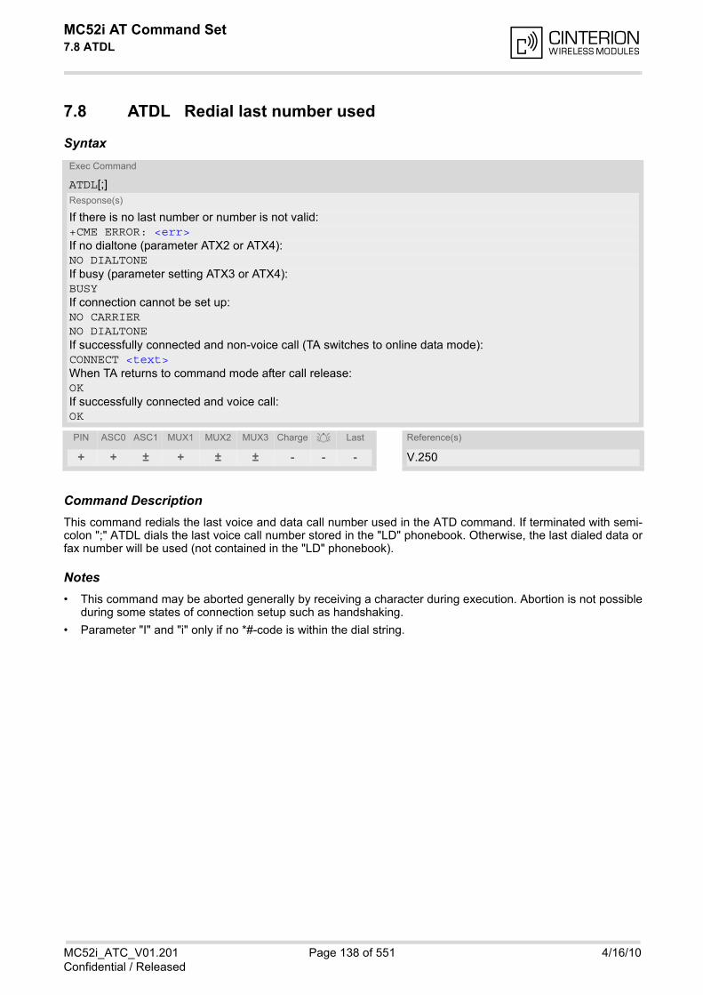
MC52i AT Command Set 7.8 ATDL
MC52i_ATC_V01.201 Page 138 of 551 4/16/10Confidential / Released
7.8 ATDL Redial last number used
Syntax
Command DescriptionThis command redials the last voice and data call number used in the ATD command. If terminated with semi-colon ";" ATDL dials the last voice call number stored in the "LD" phonebook. Otherwise, the last dialed data orfax number will be used (not contained in the "LD" phonebook).
Notes• This command may be aborted generally by receiving a character during execution. Abortion is not possible
during some states of connection setup such as handshaking.
• Parameter "I" and "i" only if no *#-code is within the dial string.
Exec Command
ATDL[;]Response(s)
If there is no last number or number is not valid:+CME ERROR: <err>If no dialtone (parameter ATX2 or ATX4):NO DIALTONEIf busy (parameter setting ATX3 or ATX4):BUSYIf connection cannot be set up:NO CARRIERNO DIALTONEIf successfully connected and non-voice call (TA switches to online data mode):CONNECT <text>When TA returns to command mode after call release:OKIf successfully connected and voice call:OK
PIN ASC0 ASC1 MUX1 MUX2 MUX3 Charge Last Reference(s)
+ + ± + ± ± - - - V.250
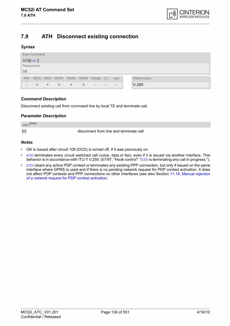
MC52i AT Command Set 7.9 ATH
MC52i_ATC_V01.201 Page 139 of 551 4/16/10Confidential / Released
7.9 ATH Disconnect existing connection
Syntax
Command DescriptionDisconnect existing call from command line by local TE and terminate call.
Parameter Description
[0] disconnect from line and terminate call
Notes• OK is issued after circuit 109 (DCD) is turned off, if it was previously on.
• ATH terminates every circuit switched call (voice, data or fax), even if it is issued via another interface. Thisbehavior is in accordance with ITU-T V.250; (07/97, "Hook control": "ATH is terminating any call in progress.").
• ATH clears any active PDP context or terminates any existing PPP connection, but only if issued on the sameinterface where GPRS is used and if there is no pending network request for PDP context activation. It doesnot affect PDP contexts and PPP connections on other interfaces (see also Section 11.18, Manual rejectionof a network request for PDP context activation.
Exec Command
ATH[<n>]Response(s)
OK
PIN ASC0 ASC1 MUX1 MUX2 MUX3 Charge Last Reference(s)
- + + + + + - - - V.250
<n>(num)
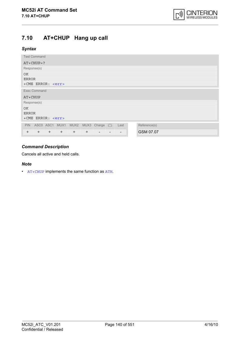
MC52i AT Command Set 7.10 AT+CHUP
MC52i_ATC_V01.201 Page 140 of 551 4/16/10Confidential / Released
7.10 AT+CHUP Hang up call
Syntax
Command DescriptionCancels all active and held calls.
Note• AT+CHUP implements the same function as ATH.
Test Command
AT+CHUP=?Response(s)
OKERROR+CME ERROR: <err>
Exec Command
AT+CHUPResponse(s)
OKERROR+CME ERROR: <err>
PIN ASC0 ASC1 MUX1 MUX2 MUX3 Charge Last Reference(s)
+ + + + + + - - - GSM 07.07

MC52i AT Command Set 7.11 AT^SHUP
MC52i_ATC_V01.201 Page 141 of 551 4/16/10Confidential / Released
7.11 AT^SHUP Hang up call(s) indicating a specific GSM04.08 release cause
The AT^SHUP write command terminates calls known to the ME and indicates a specific GSM04.08 releasecause specified by the user. The command can be used for voice, fax and data calls. Calls will be terminatedregardless of their current call status, which may be any of the states listed with AT+CLCC.
Syntax
Parameter Description
Release cause
GSM04.08 release cause to be indicated to the network. The MC52i will release the selected connection(s) with release cause indication "cause" and location "user" (0)in the "disconnect" protocol message to the network. It depends on the network whether or not the release causewill be forwarded to the remote party.
1 Send GSM04.08 release cause "unassigned (unallocated) number"
16 Send GSM04.08 release cause "normal call clearing "
17 Send GSM04.08 release cause "user busy "
18 Send GSM04.08 release cause "no user responding "
27 Send GSM04.08 release cause "destination out of order "
31 Send GSM04.08 release cause "normal, unspecified"
Call number
The "call number" is an optional index used in the list of current calls indicated by AT+CLCC. The AT^SHUP com-mand will terminate the call identified by the given call number. The default call number "0" is not assigned toany call, but signifies "all calls". As "0" is the default value, it may be omitted.
[0] Terminate all known calls.
1...7 Terminate the specific call number <cn>.
Test Command
AT^SHUP=?Response(s)
OK
Write Command
AT^SHUP=<cause>[, <cn>]Response(s)
OKERROR
PIN ASC0 ASC1 MUX1 MUX2 MUX3 Charge Last
+ + + + + + - - -
<cause>(num)
<cn>(num)
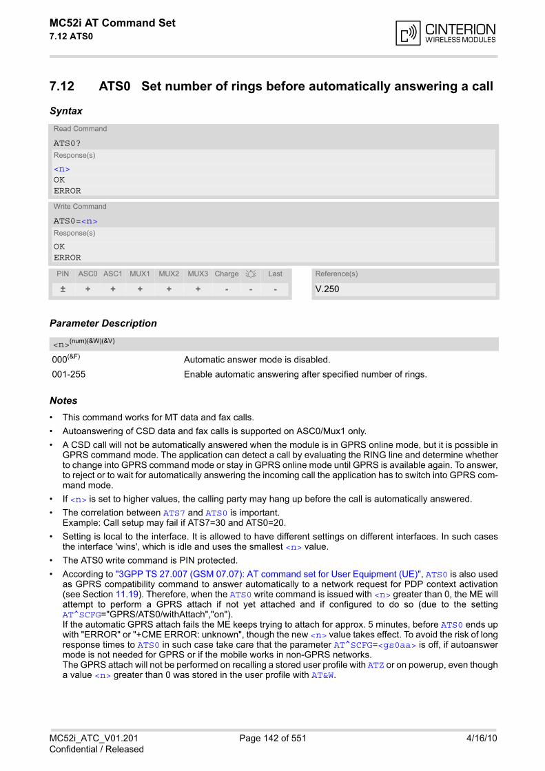
MC52i AT Command Set 7.12 ATS0
MC52i_ATC_V01.201 Page 142 of 551 4/16/10Confidential / Released
7.12 ATS0 Set number of rings before automatically answering a call
Syntax
Parameter Description
000(&F) Automatic answer mode is disabled.
001-255 Enable automatic answering after specified number of rings.
Notes• This command works for MT data and fax calls.
• Autoanswering of CSD data and fax calls is supported on ASC0/Mux1 only.
• A CSD call will not be automatically answered when the module is in GPRS online mode, but it is possible inGPRS command mode. The application can detect a call by evaluating the RING line and determine whetherto change into GPRS command mode or stay in GPRS online mode until GPRS is available again. To answer,to reject or to wait for automatically answering the incoming call the application has to switch into GPRS com-mand mode.
• If <n> is set to higher values, the calling party may hang up before the call is automatically answered.
• The correlation between ATS7 and ATS0 is important.Example: Call setup may fail if ATS7=30 and ATS0=20.
• Setting is local to the interface. It is allowed to have different settings on different interfaces. In such casesthe interface 'wins', which is idle and uses the smallest <n> value.
• The ATS0 write command is PIN protected.
• According to "3GPP TS 27.007 (GSM 07.07): AT command set for User Equipment (UE)", ATS0 is also usedas GPRS compatibility command to answer automatically to a network request for PDP context activation(see Section 11.19). Therefore, when the ATS0 write command is issued with <n> greater than 0, the ME willattempt to perform a GPRS attach if not yet attached and if configured to do so (due to the settingAT^SCFG="GPRS/ATS0/withAttach","on"). If the automatic GPRS attach fails the ME keeps trying to attach for approx. 5 minutes, before ATS0 ends upwith "ERROR" or "+CME ERROR: unknown", though the new <n> value takes effect. To avoid the risk of longresponse times to ATS0 in such case take care that the parameter AT^SCFG=<gs0aa> is off, if autoanswermode is not needed for GPRS or if the mobile works in non-GPRS networks. The GPRS attach will not be performed on recalling a stored user profile with ATZ or on powerup, even thougha value <n> greater than 0 was stored in the user profile with AT&W.
Read Command
ATS0?Response(s)
<n>OKERROR
Write Command
ATS0=<n>Response(s)
OKERROR
PIN ASC0 ASC1 MUX1 MUX2 MUX3 Charge Last Reference(s)
± + + + + + - - - V.250
<n>(num)(&W)(&V)
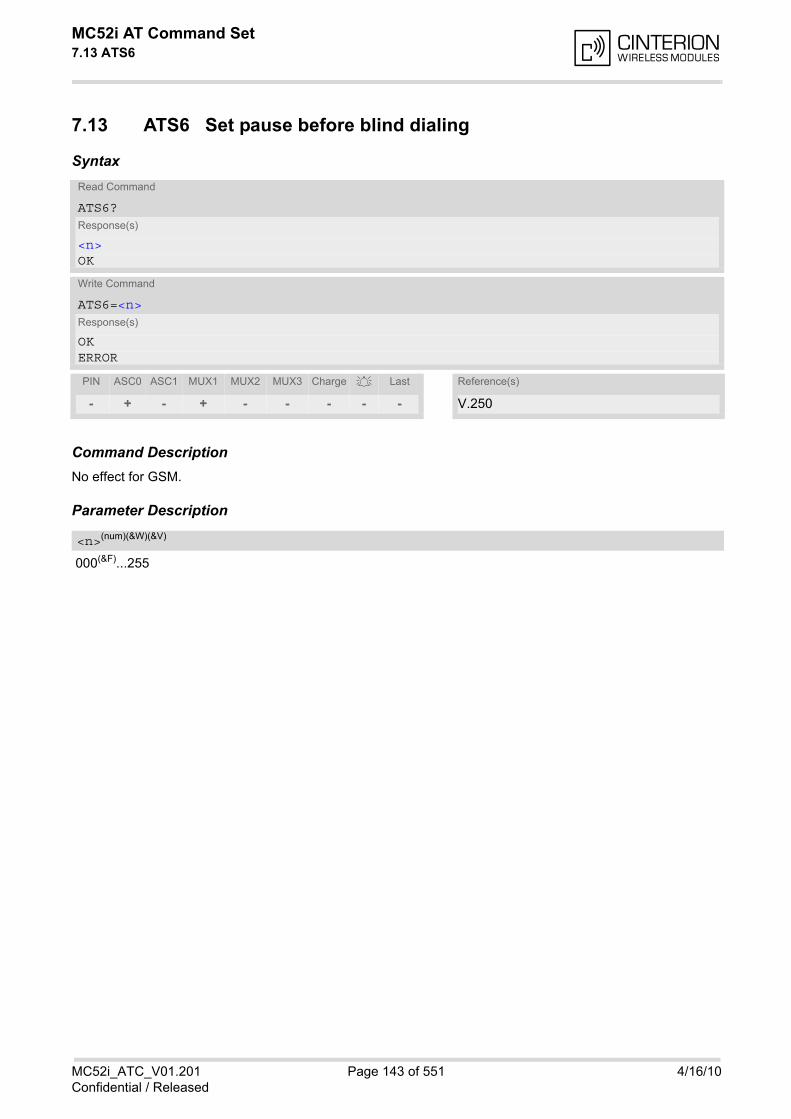
MC52i AT Command Set 7.13 ATS6
MC52i_ATC_V01.201 Page 143 of 551 4/16/10Confidential / Released
7.13 ATS6 Set pause before blind dialing
Syntax
Command DescriptionNo effect for GSM.
Parameter Description
000(&F)...255
Read Command
ATS6?Response(s)
<n>OK
Write Command
ATS6=<n>Response(s)
OKERROR
PIN ASC0 ASC1 MUX1 MUX2 MUX3 Charge Last Reference(s)
- + - + - - - - - V.250
<n>(num)(&W)(&V)
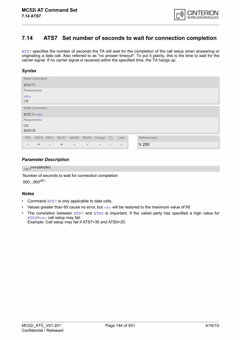
MC52i AT Command Set 7.14 ATS7
MC52i_ATC_V01.201 Page 144 of 551 4/16/10Confidential / Released
7.14 ATS7 Set number of seconds to wait for connection completion
ATS7 specifies the number of seconds the TA will wait for the completion of the call setup when answering ororiginating a data call. Also referred to as "no answer timeout". To put it plainly, this is the time to wait for thecarrier signal. If no carrier signal is received within the specified time, the TA hangs up.
Syntax
Parameter Description
Number of seconds to wait for connection completion
000...060(&F)
Notes• Command ATS7 is only applicable to data calls.
• Values greater than 60 cause no error, but <n> will be restored to the maximum value of 60.
• The correlation between ATS7 and ATS0 is important. If the called party has specified a high value forATS0=<n> call setup may fail. Example: Call setup may fail if ATS7=30 and ATS0=20.
Read Command
ATS7?Response(s)
<n>OK
Write Command
ATS7=<n>Response(s)
OKERROR
PIN ASC0 ASC1 MUX1 MUX2 MUX3 Charge Last Reference(s)
- + - + - - - - - V.250
<n>(num)(&W)(&V)
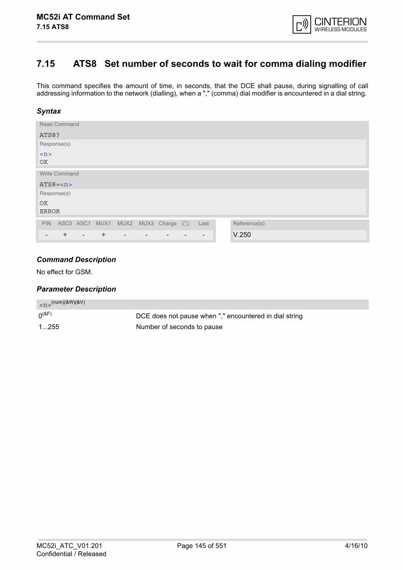
MC52i AT Command Set 7.15 ATS8
MC52i_ATC_V01.201 Page 145 of 551 4/16/10Confidential / Released
7.15 ATS8 Set number of seconds to wait for comma dialing modifier
This command specifies the amount of time, in seconds, that the DCE shall pause, during signalling of calladdressing information to the network (dialling), when a "," (comma) dial modifier is encountered in a dial string.
Syntax
Command DescriptionNo effect for GSM.
Parameter Description
0(&F) DCE does not pause when "," encountered in dial string
1...255 Number of seconds to pause
Read Command
ATS8?Response(s)
<n>OK
Write Command
ATS8=<n>Response(s)
OKERROR
PIN ASC0 ASC1 MUX1 MUX2 MUX3 Charge Last Reference(s)
- + - + - - - - - V.250
<n>(num)(&W)(&V)
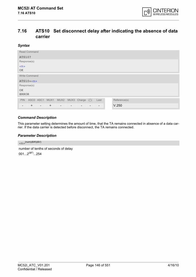
MC52i AT Command Set 7.16 ATS10
MC52i_ATC_V01.201 Page 146 of 551 4/16/10Confidential / Released
7.16 ATS10 Set disconnect delay after indicating the absence of data carrier
Syntax
Command DescriptionThis parameter setting determines the amount of time, that the TA remains connected in absence of a data car-rier. If the data carrier is detected before disconnect, the TA remains connected.
Parameter Description
number of tenths of seconds of delay
001...2(&F)...254
Read Command
ATS10?Response(s)
<n>OK
Write Command
ATS10=<n>Response(s)
OKERROR
PIN ASC0 ASC1 MUX1 MUX2 MUX3 Charge Last Reference(s)
- + - + - - - - - V.250
<n>(num)(&W)(&V)
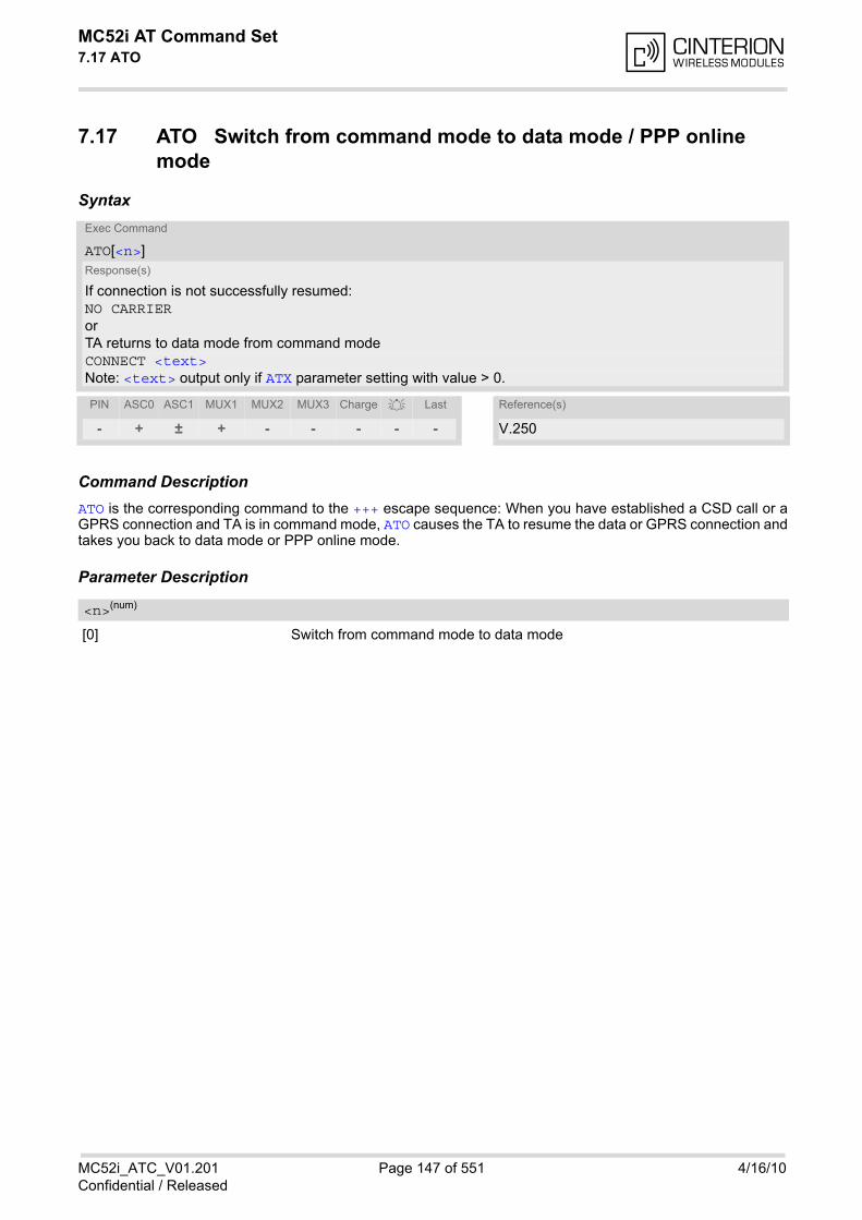
MC52i AT Command Set 7.17 ATO
MC52i_ATC_V01.201 Page 147 of 551 4/16/10Confidential / Released
7.17 ATO Switch from command mode to data mode / PPP online mode
Syntax
Command DescriptionATO is the corresponding command to the +++ escape sequence: When you have established a CSD call or aGPRS connection and TA is in command mode, ATO causes the TA to resume the data or GPRS connection andtakes you back to data mode or PPP online mode.
Parameter Description
[0] Switch from command mode to data mode
Exec Command
ATO[<n>]Response(s)
If connection is not successfully resumed:NO CARRIERorTA returns to data mode from command modeCONNECT <text>Note: <text> output only if ATX parameter setting with value > 0.
PIN ASC0 ASC1 MUX1 MUX2 MUX3 Charge Last Reference(s)
- + ± + - - - - - V.250
<n>(num)
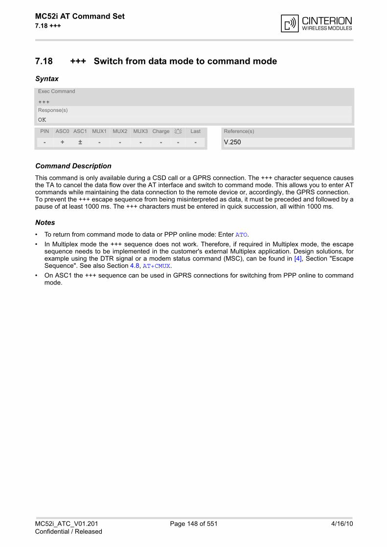
MC52i AT Command Set 7.18 +++
MC52i_ATC_V01.201 Page 148 of 551 4/16/10Confidential / Released
7.18 +++ Switch from data mode to command mode
Syntax
Command DescriptionThis command is only available during a CSD call or a GPRS connection. The +++ character sequence causesthe TA to cancel the data flow over the AT interface and switch to command mode. This allows you to enter ATcommands while maintaining the data connection to the remote device or, accordingly, the GPRS connection. To prevent the +++ escape sequence from being misinterpreted as data, it must be preceded and followed by apause of at least 1000 ms. The +++ characters must be entered in quick succession, all within 1000 ms.
Notes• To return from command mode to data or PPP online mode: Enter ATO.
• In Multiplex mode the +++ sequence does not work. Therefore, if required in Multiplex mode, the escapesequence needs to be implemented in the customer's external Multiplex application. Design solutions, forexample using the DTR signal or a modem status command (MSC), can be found in [4], Section "EscapeSequence". See also Section 4.8, AT+CMUX.
• On ASC1 the +++ sequence can be used in GPRS connections for switching from PPP online to commandmode.
Exec Command
+++Response(s)
OK
PIN ASC0 ASC1 MUX1 MUX2 MUX3 Charge Last Reference(s)
- + ± - - - - - - V.250
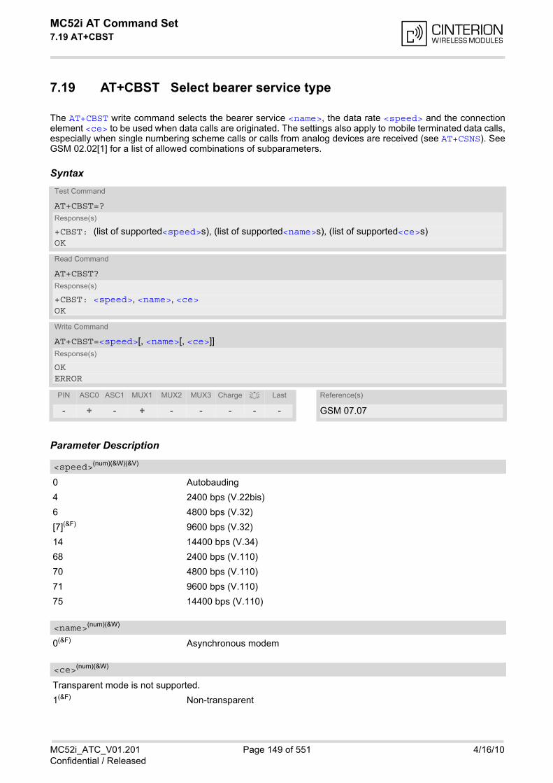
MC52i AT Command Set 7.19 AT+CBST
MC52i_ATC_V01.201 Page 149 of 551 4/16/10Confidential / Released
7.19 AT+CBST Select bearer service type
The AT+CBST write command selects the bearer service <name>, the data rate <speed> and the connectionelement <ce> to be used when data calls are originated. The settings also apply to mobile terminated data calls,especially when single numbering scheme calls or calls from analog devices are received (see AT+CSNS). SeeGSM 02.02[1] for a list of allowed combinations of subparameters.
Syntax
Parameter Description
0 Autobauding
4 2400 bps (V.22bis)
6 4800 bps (V.32)
[7](&F) 9600 bps (V.32)
14 14400 bps (V.34)
68 2400 bps (V.110)
70 4800 bps (V.110)
71 9600 bps (V.110)
75 14400 bps (V.110)
0(&F) Asynchronous modem
Transparent mode is not supported.
1(&F) Non-transparent
Test Command
AT+CBST=?Response(s)
+CBST: (list of supported<speed>s), (list of supported<name>s), (list of supported<ce>s)OK
Read Command
AT+CBST?Response(s)
+CBST: <speed>, <name>, <ce>OK
Write Command
AT+CBST=<speed>[, <name>[, <ce>]]Response(s)
OKERROR
PIN ASC0 ASC1 MUX1 MUX2 MUX3 Charge Last Reference(s)
- + - + - - - - - GSM 07.07
<speed>(num)(&W)(&V)
<name>(num)(&W)
<ce>(num)(&W)
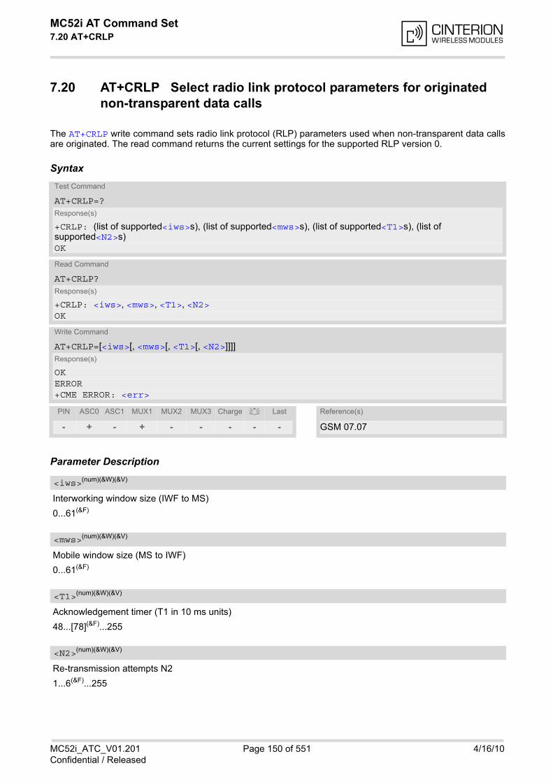
MC52i AT Command Set 7.20 AT+CRLP
MC52i_ATC_V01.201 Page 150 of 551 4/16/10Confidential / Released
7.20 AT+CRLP Select radio link protocol parameters for originated non-transparent data calls
The AT+CRLP write command sets radio link protocol (RLP) parameters used when non-transparent data callsare originated. The read command returns the current settings for the supported RLP version 0.
Syntax
Parameter Description
Interworking window size (IWF to MS)
0...61(&F)
Mobile window size (MS to IWF)
0...61(&F)
Acknowledgement timer (T1 in 10 ms units)
48...[78](&F)...255
Re-transmission attempts N2
1...6(&F)...255
Test Command
AT+CRLP=?Response(s)
+CRLP: (list of supported<iws>s), (list of supported<mws>s), (list of supported<T1>s), (list of supported<N2>s)OK
Read Command
AT+CRLP?Response(s)
+CRLP: <iws>, <mws>, <T1>, <N2>OK
Write Command
AT+CRLP=[<iws>[, <mws>[, <T1>[, <N2>]]]]Response(s)
OKERROR+CME ERROR: <err>
PIN ASC0 ASC1 MUX1 MUX2 MUX3 Charge Last Reference(s)
- + - + - - - - - GSM 07.07
<iws>(num)(&W)(&V)
<mws>(num)(&W)(&V)
<T1>(num)(&W)(&V)
<N2>(num)(&W)(&V)

MC52i AT Command Set 7.21 AT+CLCC
MC52i_ATC_V01.201 Page 151 of 551 4/16/10Confidential / Released
7.21 AT+CLCC List of current calls
The execute command lists all current calls. If the command is successful, but no calls are available, no infor-mation response is sent to TE.
Syntax
Parameter Description
Call identification number as described in GSM02.30 subclause 4.5.5.1; this number can be used in AT+CHLDcommand operations
0 Mobile originated call (MOC)
1 Mobile terminated call (MTC)
State of the call
0 Active
1 Held
2 Dialing (MOC)
3 Alerting (MOC)
4 Incoming (MTC)
5 Waiting (MTC)
Bearer/teleservice
0 Voice
1 Data
2 Fax
Test Command
AT+CLCC=?Response(s)
OK
Exec Command
AT+CLCCResponse(s)
[+CLCC: <idx>, <dir>, <stat>, <mode>, <mpty>[, <number>, <type>[, <alpha>]]][+CLCC: <idx>, <dir>, <stat>, <mode>, <mpty>[, <number>, <type>[, <alpha>]]][+CLCC: ...]OKERROR+CME ERROR: <err>
PIN ASC0 ASC1 MUX1 MUX2 MUX3 Charge Last Reference(s)
+ + + + + + - - - GSM 07.07
<idx>(num)
<dir>(num)
<stat>(num)
<mode>(num)
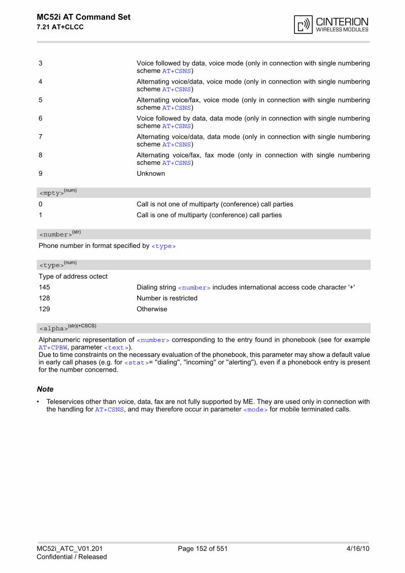
MC52i AT Command Set 7.21 AT+CLCC
MC52i_ATC_V01.201 Page 152 of 551 4/16/10Confidential / Released
3 Voice followed by data, voice mode (only in connection with single numberingscheme AT+CSNS)
4 Alternating voice/data, voice mode (only in connection with single numberingscheme AT+CSNS)
5 Alternating voice/fax, voice mode (only in connection with single numberingscheme AT+CSNS)
6 Voice followed by data, data mode (only in connection with single numberingscheme AT+CSNS)
7 Alternating voice/data, data mode (only in connection with single numberingscheme AT+CSNS)
8 Alternating voice/fax, fax mode (only in connection with single numberingscheme AT+CSNS)
9 Unknown
0 Call is not one of multiparty (conference) call parties
1 Call is one of multiparty (conference) call parties
Phone number in format specified by <type>
Type of address octect
145 Dialing string <number> includes international access code character '+'
128 Number is restricted
129 Otherwise
Alphanumeric representation of <number> corresponding to the entry found in phonebook (see for exampleAT+CPBW, parameter <text>). Due to time constraints on the necessary evaluation of the phonebook, this parameter may show a default valuein early call phases (e.g. for <stat>= ''dialing'', ''incoming'' or ''alerting''), even if a phonebook entry is presentfor the number concerned.
Note• Teleservices other than voice, data, fax are not fully supported by ME. They are used only in connection with
the handling for AT+CSNS, and may therefore occur in parameter <mode> for mobile terminated calls.
<mpty>(num)
<number>(str)
<type>(num)
<alpha>(str)(+CSCS)
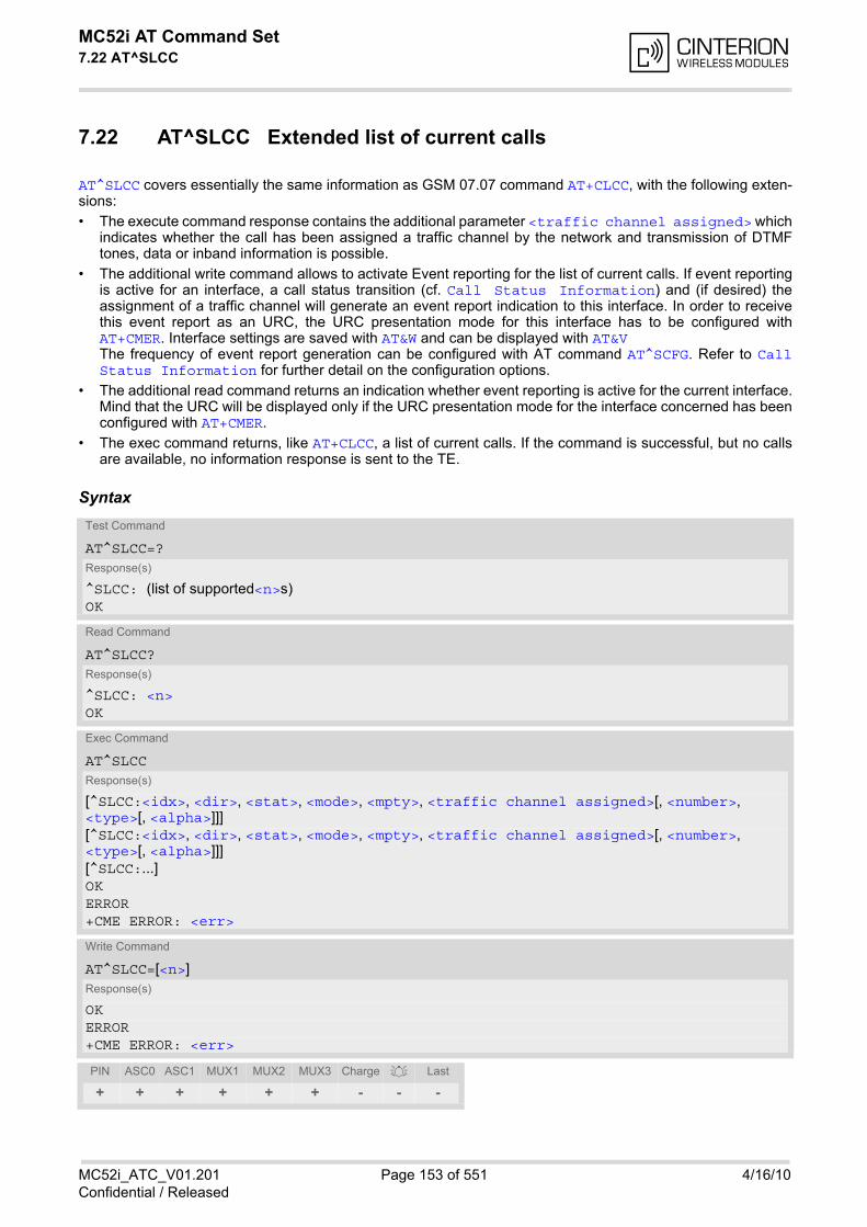
MC52i AT Command Set 7.22 AT^SLCC
MC52i_ATC_V01.201 Page 153 of 551 4/16/10Confidential / Released
7.22 AT^SLCC Extended list of current calls
AT^SLCC covers essentially the same information as GSM 07.07 command AT+CLCC, with the following exten-sions:
• The execute command response contains the additional parameter <traffic channel assigned> whichindicates whether the call has been assigned a traffic channel by the network and transmission of DTMFtones, data or inband information is possible.
• The additional write command allows to activate Event reporting for the list of current calls. If event reportingis active for an interface, a call status transition (cf. Call Status Information) and (if desired) theassignment of a traffic channel will generate an event report indication to this interface. In order to receivethis event report as an URC, the URC presentation mode for this interface has to be configured withAT+CMER. Interface settings are saved with AT&W and can be displayed with AT&VThe frequency of event report generation can be configured with AT command AT^SCFG. Refer to CallStatus Information for further detail on the configuration options.
• The additional read command returns an indication whether event reporting is active for the current interface.Mind that the URC will be displayed only if the URC presentation mode for the interface concerned has beenconfigured with AT+CMER.
• The exec command returns, like AT+CLCC, a list of current calls. If the command is successful, but no callsare available, no information response is sent to the TE.
SyntaxTest Command
AT^SLCC=?Response(s)
^SLCC: (list of supported<n>s)OK
Read Command
AT^SLCC?Response(s)
^SLCC: <n>OK
Exec Command
AT^SLCCResponse(s)
[^SLCC:<idx>, <dir>, <stat>, <mode>, <mpty>, <traffic channel assigned>[, <number>, <type>[, <alpha>]]][^SLCC:<idx>, <dir>, <stat>, <mode>, <mpty>, <traffic channel assigned>[, <number>, <type>[, <alpha>]]][^SLCC:...]OKERROR+CME ERROR: <err>
Write Command
AT^SLCC=[<n>]Response(s)
OKERROR+CME ERROR: <err>
PIN ASC0 ASC1 MUX1 MUX2 MUX3 Charge Last
+ + + + + + - - -
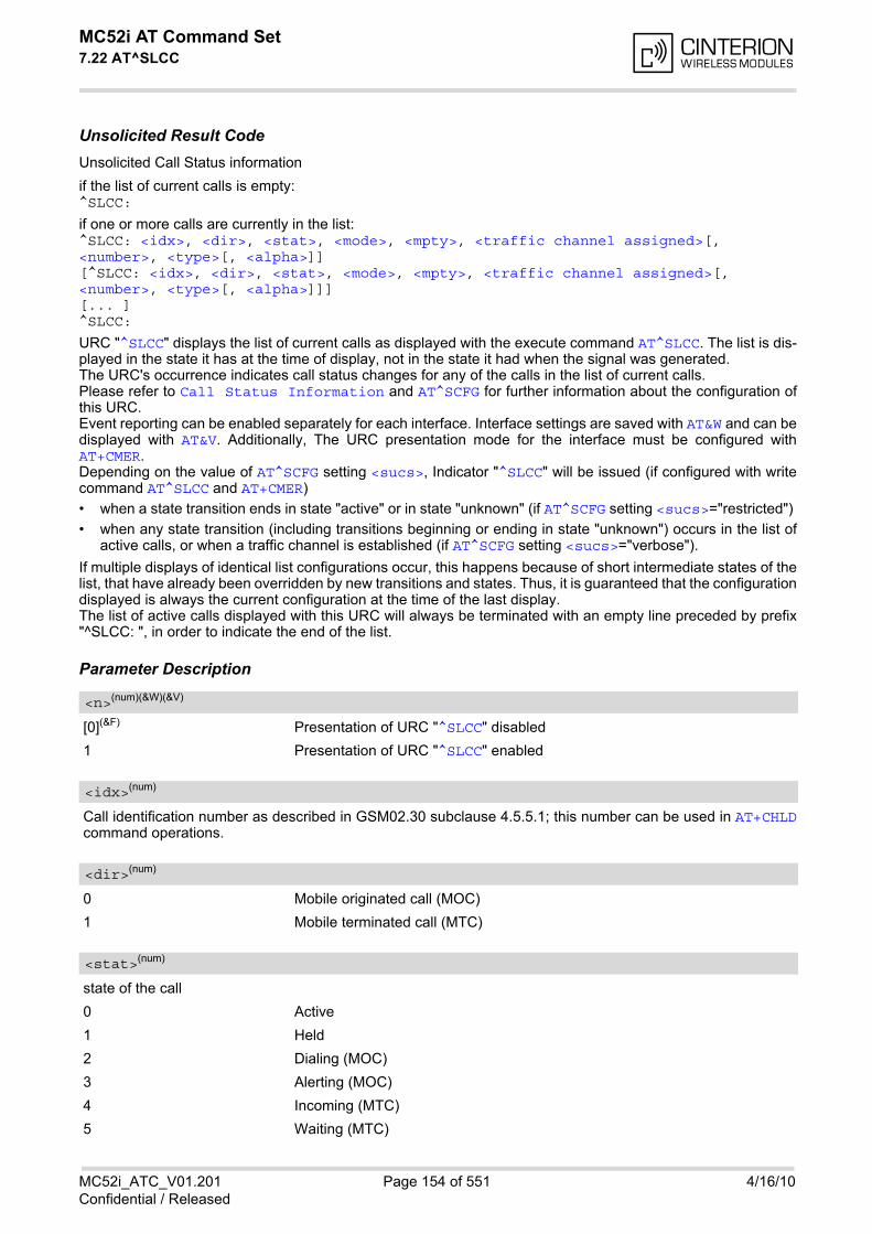
MC52i AT Command Set 7.22 AT^SLCC
MC52i_ATC_V01.201 Page 154 of 551 4/16/10Confidential / Released
Unsolicited Result CodeUnsolicited Call Status information
if the list of current calls is empty: ^SLCC:
if one or more calls are currently in the list: ^SLCC: <idx>, <dir>, <stat>, <mode>, <mpty>, <traffic channel assigned>[, <number>, <type>[, <alpha>]][^SLCC: <idx>, <dir>, <stat>, <mode>, <mpty>, <traffic channel assigned>[, <number>, <type>[, <alpha>]]][... ]^SLCC:
URC "^SLCC" displays the list of current calls as displayed with the execute command AT^SLCC. The list is dis-played in the state it has at the time of display, not in the state it had when the signal was generated.The URC's occurrence indicates call status changes for any of the calls in the list of current calls.Please refer to Call Status Information and AT^SCFG for further information about the configuration ofthis URC.Event reporting can be enabled separately for each interface. Interface settings are saved with AT&W and can bedisplayed with AT&V. Additionally, The URC presentation mode for the interface must be configured withAT+CMER.Depending on the value of AT^SCFG setting <sucs>, Indicator "^SLCC" will be issued (if configured with writecommand AT^SLCC and AT+CMER)
• when a state transition ends in state "active" or in state "unknown" (if AT^SCFG setting <sucs>="restricted")
• when any state transition (including transitions beginning or ending in state "unknown") occurs in the list ofactive calls, or when a traffic channel is established (if AT^SCFG setting <sucs>="verbose").
If multiple displays of identical list configurations occur, this happens because of short intermediate states of thelist, that have already been overridden by new transitions and states. Thus, it is guaranteed that the configurationdisplayed is always the current configuration at the time of the last display.The list of active calls displayed with this URC will always be terminated with an empty line preceded by prefix"^SLCC: ", in order to indicate the end of the list.
Parameter Description
[0](&F) Presentation of URC "^SLCC" disabled
1 Presentation of URC "^SLCC" enabled
Call identification number as described in GSM02.30 subclause 4.5.5.1; this number can be used in AT+CHLDcommand operations.
0 Mobile originated call (MOC)
1 Mobile terminated call (MTC)
state of the call
0 Active
1 Held
2 Dialing (MOC)
3 Alerting (MOC)
4 Incoming (MTC)
5 Waiting (MTC)
<n>(num)(&W)(&V)
<idx>(num)
<dir>(num)
<stat>(num)
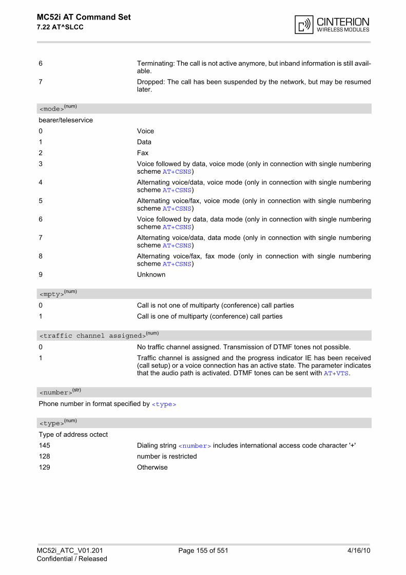
MC52i AT Command Set 7.22 AT^SLCC
MC52i_ATC_V01.201 Page 155 of 551 4/16/10Confidential / Released
6 Terminating: The call is not active anymore, but inband information is still avail-able.
7 Dropped: The call has been suspended by the network, but may be resumedlater.
bearer/teleservice
0 Voice
1 Data
2 Fax
3 Voice followed by data, voice mode (only in connection with single numberingscheme AT+CSNS)
4 Alternating voice/data, voice mode (only in connection with single numberingscheme AT+CSNS)
5 Alternating voice/fax, voice mode (only in connection with single numberingscheme AT+CSNS)
6 Voice followed by data, data mode (only in connection with single numberingscheme AT+CSNS)
7 Alternating voice/data, data mode (only in connection with single numberingscheme AT+CSNS)
8 Alternating voice/fax, fax mode (only in connection with single numberingscheme AT+CSNS)
9 Unknown
0 Call is not one of multiparty (conference) call parties
1 Call is one of multiparty (conference) call parties
0 No traffic channel assigned. Transmission of DTMF tones not possible.
1 Traffic channel is assigned and the progress indicator IE has been received(call setup) or a voice connection has an active state. The parameter indicatesthat the audio path is activated. DTMF tones can be sent with AT+VTS.
Phone number in format specified by <type>
Type of address octect
145 Dialing string <number> includes international access code character '+'
128 number is restricted
129 Otherwise
<mode>(num)
<mpty>(num)
<traffic channel assigned>(num)
<number>(str)
<type>(num)
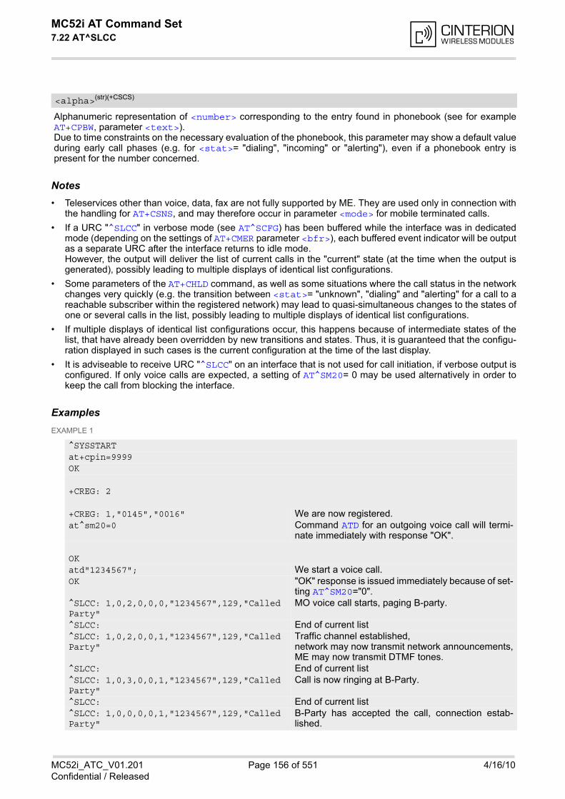
MC52i AT Command Set 7.22 AT^SLCC
MC52i_ATC_V01.201 Page 156 of 551 4/16/10Confidential / Released
Alphanumeric representation of <number> corresponding to the entry found in phonebook (see for exampleAT+CPBW, parameter <text>). Due to time constraints on the necessary evaluation of the phonebook, this parameter may show a default valueduring early call phases (e.g. for <stat>= "dialing", "incoming" or "alerting"), even if a phonebook entry ispresent for the number concerned.
Notes• Teleservices other than voice, data, fax are not fully supported by ME. They are used only in connection with
the handling for AT+CSNS, and may therefore occur in parameter <mode> for mobile terminated calls.
• If a URC "^SLCC" in verbose mode (see AT^SCFG) has been buffered while the interface was in dedicatedmode (depending on the settings of AT+CMER parameter <bfr>), each buffered event indicator will be outputas a separate URC after the interface returns to idle mode. However, the output will deliver the list of current calls in the "current" state (at the time when the output isgenerated), possibly leading to multiple displays of identical list configurations.
• Some parameters of the AT+CHLD command, as well as some situations where the call status in the networkchanges very quickly (e.g. the transition between <stat>= "unknown", "dialing" and "alerting" for a call to areachable subscriber within the registered network) may lead to quasi-simultaneous changes to the states ofone or several calls in the list, possibly leading to multiple displays of identical list configurations.
• If multiple displays of identical list configurations occur, this happens because of intermediate states of thelist, that have already been overridden by new transitions and states. Thus, it is guaranteed that the configu-ration displayed in such cases is the current configuration at the time of the last display.
• It is adviseable to receive URC "^SLCC" on an interface that is not used for call initiation, if verbose output isconfigured. If only voice calls are expected, a setting of AT^SM20= 0 may be used alternatively in order tokeep the call from blocking the interface.
ExamplesEXAMPLE 1
<alpha>(str)(+CSCS)
^SYSSTARTat+cpin=9999OK
+CREG: 2
+CREG: 1,"0145","0016" We are now registered.at^sm20=0 Command ATD for an outgoing voice call will termi-
nate immediately with response "OK".
OKatd"1234567"; We start a voice call.OK "OK" response is issued immediately because of set-
ting AT^SM20="0". ^SLCC: 1,0,2,0,0,0,"1234567",129,"Called Party"
MO voice call starts, paging B-party.
^SLCC: End of current list^SLCC: 1,0,2,0,0,1,"1234567",129,"Called Party"
Traffic channel established, network may now transmit network announcements,ME may now transmit DTMF tones.
^SLCC: End of current list^SLCC: 1,0,3,0,0,1,"1234567",129,"Called Party"
Call is now ringing at B-Party.
^SLCC: End of current list^SLCC: 1,0,0,0,0,1,"1234567",129,"Called Party"
B-Party has accepted the call, connection estab-lished.
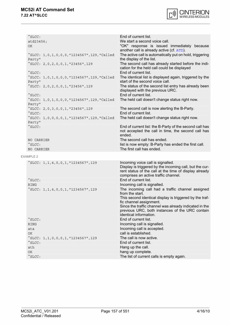
MC52i AT Command Set 7.22 AT^SLCC
MC52i_ATC_V01.201 Page 157 of 551 4/16/10Confidential / Released
EXAMPLE 2
^SLCC: End of current list.atd23456; We start a second voice call.OK "OK" response is issued immediately because
another call is already active (cf. ATD).^SLCC: 1,0,1,0,0,0,"1234567",129,"Called Party"
The active call is automatically put on hold, triggeringthe display of the list.
^SLCC: 2,0,2,0,0,1,"23456",129 The second call has already started before the indi-cation for the held call could be displayed
^SLCC: End of current list.^SLCC: 1,0,1,0,0,0,"1234567",129,"Called Party"
The identical list is displayed again, triggered by thestart of the second voice call.
^SLCC: 2,0,2,0,0,1,"23456",129 The status of the second list entry has already beendisplayed with the previous URC.
^SLCC: End of current list.^SLCC: 1,0,1,0,0,0,"1234567",129,"Called Party"
The held call doesn't change status right now.
^SLCC: 2,0,3,0,0,1,"23456",129 The second call is now alerting the B-Party.^SLCC: End of current list.^SLCC: 1,0,0,0,0,1,"1234567",129,"Called Party"
The held call doesn't change status right now.
^SLCC: End of current list: the B-Party of the second call hasnot accepted the call in time, the second call hasended.
NO CARRIER The second call has ended.^SLCC: list is now empty: B-Party has ended the first call.NO CARRIER The first call has ended.
^SLCC: 1,1,4,0,0,1,"1234567",129 Incoming voice call is signalled.Display is triggered by the incoming call, but the cur-rent status of the call at the time of display alreadycomprises an active traffic channel.
^SLCC: End of current list.RING Incoming call is signalled.^SLCC: 1,1,4,0,0,1,"1234567",129 The incoming call had a traffic channel assigned
from the start.This second identical display is triggered by the traf-fic channel assignment.Since the traffic channel was already indicated in theprevious URC, both instances of the URC containidentical information.
^SLCC: End of current list.RING Incoming call is signalled.ata Incoming call is accepted.OK call is established.^SLCC: 1,1,0,0,0,1,"1234567",129 The call is now active.^SLCC: End of current list.ath Hang up the call.OK hang up complete.^SLCC: The list of current calls is empty again.
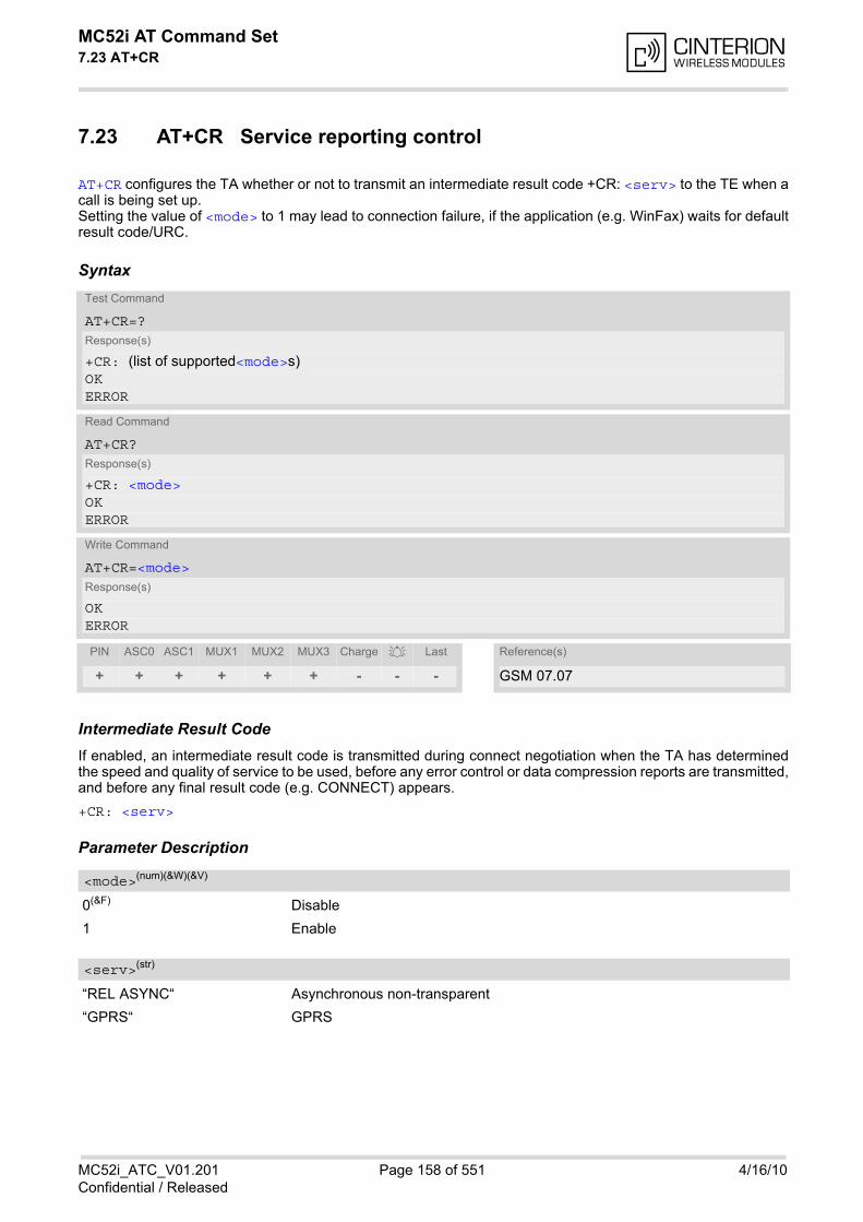
MC52i AT Command Set 7.23 AT+CR
MC52i_ATC_V01.201 Page 158 of 551 4/16/10Confidential / Released
7.23 AT+CR Service reporting control
AT+CR configures the TA whether or not to transmit an intermediate result code +CR: <serv> to the TE when acall is being set up. Setting the value of <mode> to 1 may lead to connection failure, if the application (e.g. WinFax) waits for defaultresult code/URC.
Syntax
Intermediate Result CodeIf enabled, an intermediate result code is transmitted during connect negotiation when the TA has determinedthe speed and quality of service to be used, before any error control or data compression reports are transmitted,and before any final result code (e.g. CONNECT) appears.
+CR: <serv>
Parameter Description
0(&F) Disable
1 Enable
“REL ASYNC“ Asynchronous non-transparent
“GPRS“ GPRS
Test Command
AT+CR=?Response(s)
+CR: (list of supported<mode>s)OKERROR
Read Command
AT+CR?Response(s)
+CR: <mode>OKERROR
Write Command
AT+CR=<mode>Response(s)
OKERROR
PIN ASC0 ASC1 MUX1 MUX2 MUX3 Charge Last Reference(s)
+ + + + + + - - - GSM 07.07
<mode>(num)(&W)(&V)
<serv>(str)
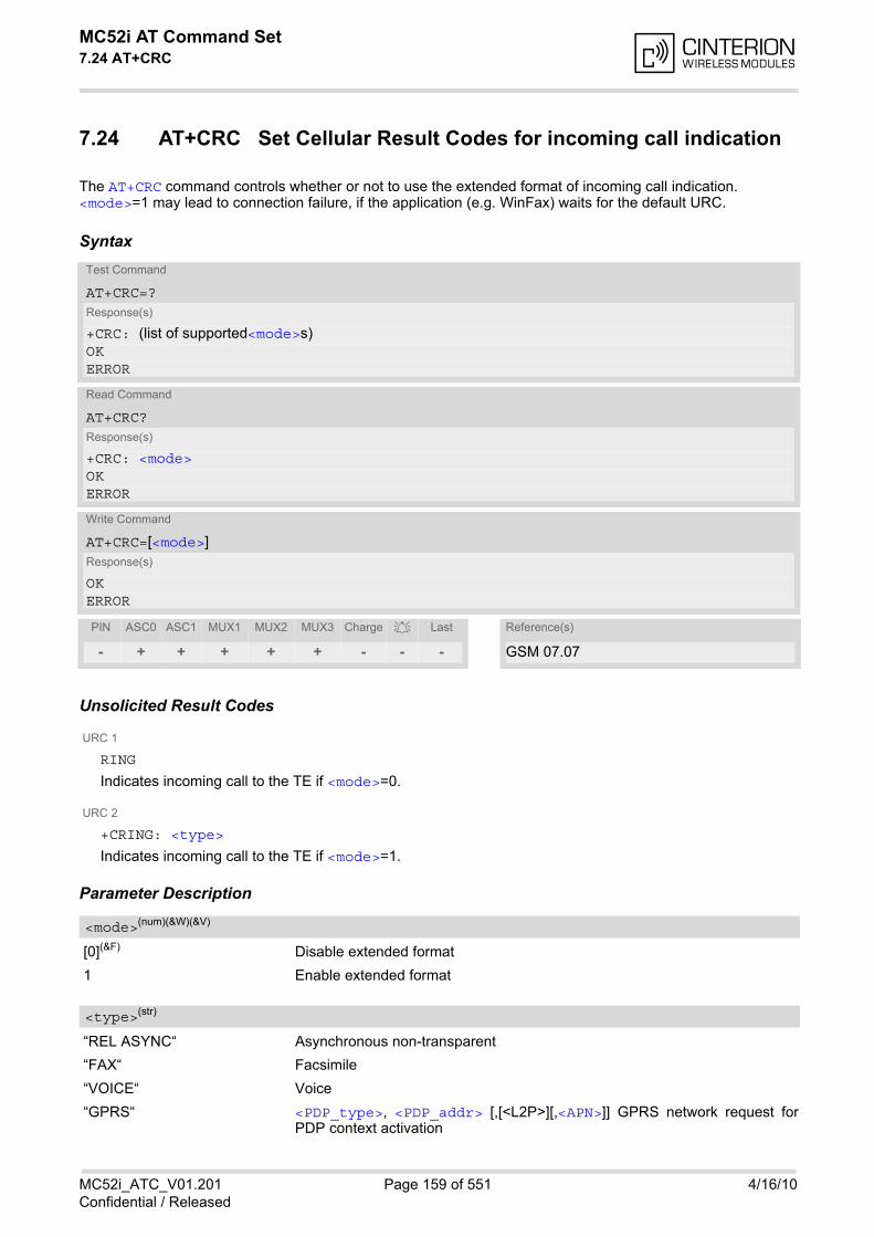
MC52i AT Command Set 7.24 AT+CRC
MC52i_ATC_V01.201 Page 159 of 551 4/16/10Confidential / Released
7.24 AT+CRC Set Cellular Result Codes for incoming call indication
The AT+CRC command controls whether or not to use the extended format of incoming call indication.<mode>=1 may lead to connection failure, if the application (e.g. WinFax) waits for the default URC.
Syntax
Unsolicited Result Codes
URC 1
RING
Indicates incoming call to the TE if <mode>=0.
URC 2
+CRING: <type>
Indicates incoming call to the TE if <mode>=1.
Parameter Description
[0](&F) Disable extended format
1 Enable extended format
“REL ASYNC“ Asynchronous non-transparent
“FAX“ Facsimile
“VOICE“ Voice
“GPRS“ <PDP_type>, <PDP_addr> [,[<L2P>][,<APN>]] GPRS network request forPDP context activation
Test Command
AT+CRC=?Response(s)
+CRC: (list of supported<mode>s)OKERROR
Read Command
AT+CRC?Response(s)
+CRC: <mode>OKERROR
Write Command
AT+CRC=[<mode>]Response(s)
OKERROR
PIN ASC0 ASC1 MUX1 MUX2 MUX3 Charge Last Reference(s)
- + + + + + - - - GSM 07.07
<mode>(num)(&W)(&V)
<type>(str)
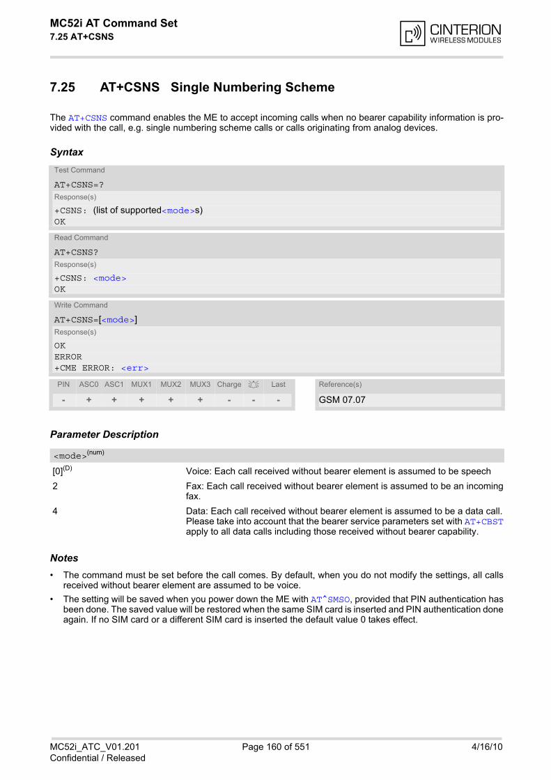
MC52i AT Command Set 7.25 AT+CSNS
MC52i_ATC_V01.201 Page 160 of 551 4/16/10Confidential / Released
7.25 AT+CSNS Single Numbering Scheme
The AT+CSNS command enables the ME to accept incoming calls when no bearer capability information is pro-vided with the call, e.g. single numbering scheme calls or calls originating from analog devices.
Syntax
Parameter Description
[0](D) Voice: Each call received without bearer element is assumed to be speech
2 Fax: Each call received without bearer element is assumed to be an incomingfax.
4 Data: Each call received without bearer element is assumed to be a data call.Please take into account that the bearer service parameters set with AT+CBSTapply to all data calls including those received without bearer capability.
Notes• The command must be set before the call comes. By default, when you do not modify the settings, all calls
received without bearer element are assumed to be voice.
• The setting will be saved when you power down the ME with AT^SMSO, provided that PIN authentication hasbeen done. The saved value will be restored when the same SIM card is inserted and PIN authentication doneagain. If no SIM card or a different SIM card is inserted the default value 0 takes effect.
Test Command
AT+CSNS=?Response(s)
+CSNS: (list of supported<mode>s)OK
Read Command
AT+CSNS?Response(s)
+CSNS: <mode>OK
Write Command
AT+CSNS=[<mode>]Response(s)
OKERROR+CME ERROR: <err>
PIN ASC0 ASC1 MUX1 MUX2 MUX3 Charge Last Reference(s)
- + + + + + - - - GSM 07.07
<mode>(num)
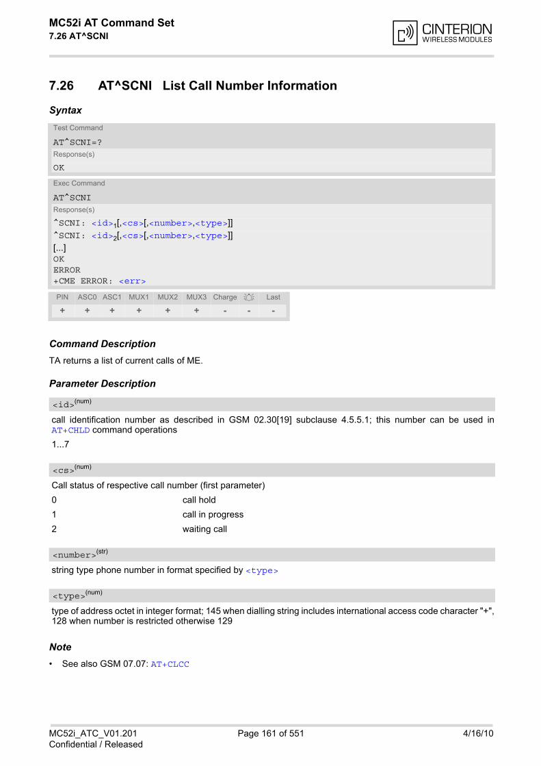
MC52i AT Command Set 7.26 AT^SCNI
MC52i_ATC_V01.201 Page 161 of 551 4/16/10Confidential / Released
7.26 AT^SCNI List Call Number Information
Syntax
Command DescriptionTA returns a list of current calls of ME.
Parameter Description
call identification number as described in GSM 02.30[19] subclause 4.5.5.1; this number can be used inAT+CHLD command operations
1...7
Call status of respective call number (first parameter)
0 call hold
1 call in progress
2 waiting call
string type phone number in format specified by <type>
type of address octet in integer format; 145 when dialling string includes international access code character "+",128 when number is restricted otherwise 129
Note• See also GSM 07.07: AT+CLCC
Test Command
AT^SCNI=?Response(s)
OK
Exec Command
AT^SCNIResponse(s)
^SCNI: <id>1[,<cs>[,<number>,<type>]]^SCNI: <id>2[,<cs>[,<number>,<type>]][...]OKERROR+CME ERROR: <err>
PIN ASC0 ASC1 MUX1 MUX2 MUX3 Charge Last
+ + + + + + - - -
<id>(num)
<cs>(num)
<number>(str)
<type>(num)
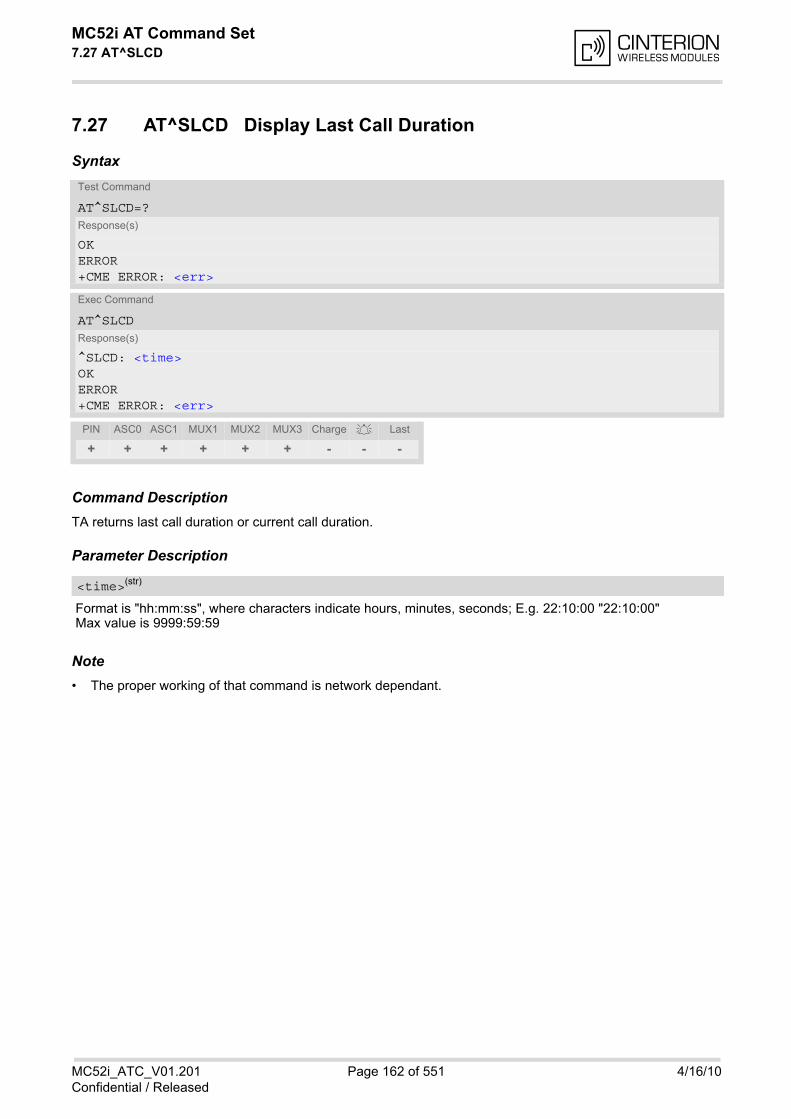
MC52i AT Command Set 7.27 AT^SLCD
MC52i_ATC_V01.201 Page 162 of 551 4/16/10Confidential / Released
7.27 AT^SLCD Display Last Call Duration
Syntax
Command DescriptionTA returns last call duration or current call duration.
Parameter Description
Format is "hh:mm:ss", where characters indicate hours, minutes, seconds; E.g. 22:10:00 "22:10:00"Max value is 9999:59:59
Note• The proper working of that command is network dependant.
Test Command
AT^SLCD=?Response(s)
OKERROR+CME ERROR: <err>
Exec Command
AT^SLCDResponse(s)
^SLCD: <time>OKERROR+CME ERROR: <err>
PIN ASC0 ASC1 MUX1 MUX2 MUX3 Charge Last
+ + + + + + - - -
<time>(str)
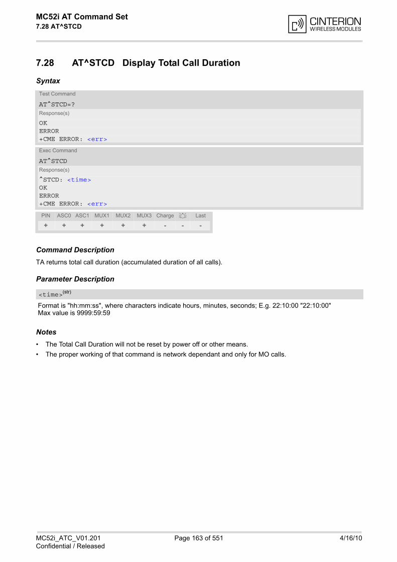
MC52i AT Command Set 7.28 AT^STCD
MC52i_ATC_V01.201 Page 163 of 551 4/16/10Confidential / Released
7.28 AT^STCD Display Total Call Duration
Syntax
Command DescriptionTA returns total call duration (accumulated duration of all calls).
Parameter Description
Format is "hh:mm:ss", where characters indicate hours, minutes, seconds; E.g. 22:10:00 "22:10:00"Max value is 9999:59:59
Notes• The Total Call Duration will not be reset by power off or other means.
• The proper working of that command is network dependant and only for MO calls.
Test Command
AT^STCD=?Response(s)
OKERROR+CME ERROR: <err>
Exec Command
AT^STCDResponse(s)
^STCD: <time>OKERROR+CME ERROR: <err>
PIN ASC0 ASC1 MUX1 MUX2 MUX3 Charge Last
+ + + + + + - - -
<time>(str)
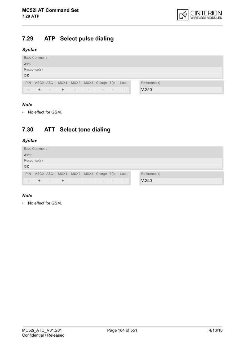
MC52i AT Command Set 7.29 ATP
MC52i_ATC_V01.201 Page 164 of 551 4/16/10Confidential / Released
7.29 ATP Select pulse dialing
Syntax
Note• No effect for GSM.
7.30 ATT Select tone dialing
Syntax
Note• No effect for GSM.
Exec Command
ATPResponse(s)
OK
PIN ASC0 ASC1 MUX1 MUX2 MUX3 Charge Last Reference(s)
- + - + - - - - - V.250
Exec Command
ATTResponse(s)
OK
PIN ASC0 ASC1 MUX1 MUX2 MUX3 Charge Last Reference(s)
- + - + - - - - - V.250
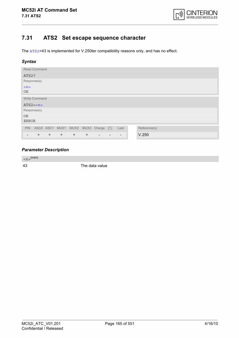
MC52i AT Command Set 7.31 ATS2
MC52i_ATC_V01.201 Page 165 of 551 4/16/10Confidential / Released
7.31 ATS2 Set escape sequence character
The ATS2=43 is implemented for V.250ter compatibility reasons only, and has no effect.
Syntax
Parameter Description
43 The data value
Read Command
ATS2?Response(s)
<n>OK
Write Command
ATS2=<n>Response(s)
OKERROR
PIN ASC0 ASC1 MUX1 MUX2 MUX3 Charge Last Reference(s)
- + + + + + - - - V.250
<n>(num)
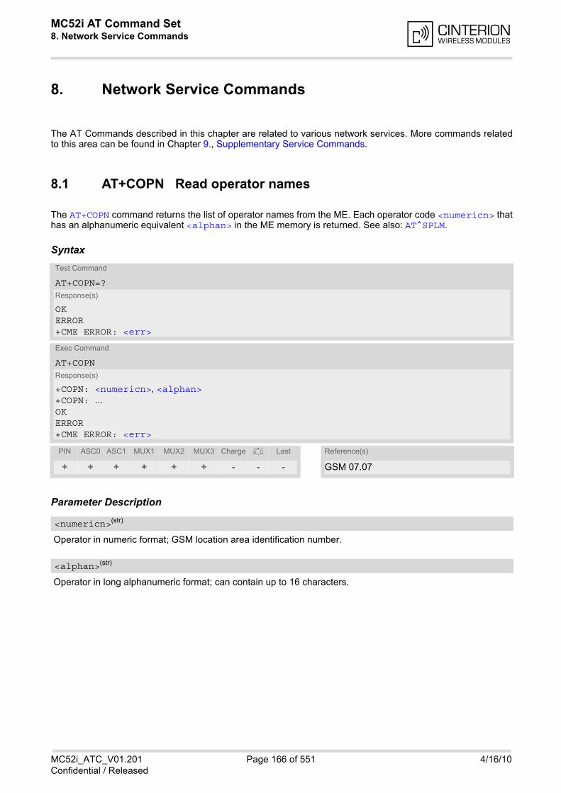
MC52i AT Command Set 8. Network Service Commands
MC52i_ATC_V01.201 Page 166 of 551 4/16/10Confidential / Released
8. Network Service Commands
The AT Commands described in this chapter are related to various network services. More commands relatedto this area can be found in Chapter 9., Supplementary Service Commands.
8.1 AT+COPN Read operator names
The AT+COPN command returns the list of operator names from the ME. Each operator code <numericn> thathas an alphanumeric equivalent <alphan> in the ME memory is returned. See also: AT^SPLM.
Syntax
Parameter Description
Operator in numeric format; GSM location area identification number.
Operator in long alphanumeric format; can contain up to 16 characters.
Test Command
AT+COPN=?Response(s)
OKERROR+CME ERROR: <err>
Exec Command
AT+COPNResponse(s)
+COPN: <numericn>, <alphan>+COPN: ...OKERROR+CME ERROR: <err>
PIN ASC0 ASC1 MUX1 MUX2 MUX3 Charge Last Reference(s)
+ + + + + + - - - GSM 07.07
<numericn>(str)
<alphan>(str)
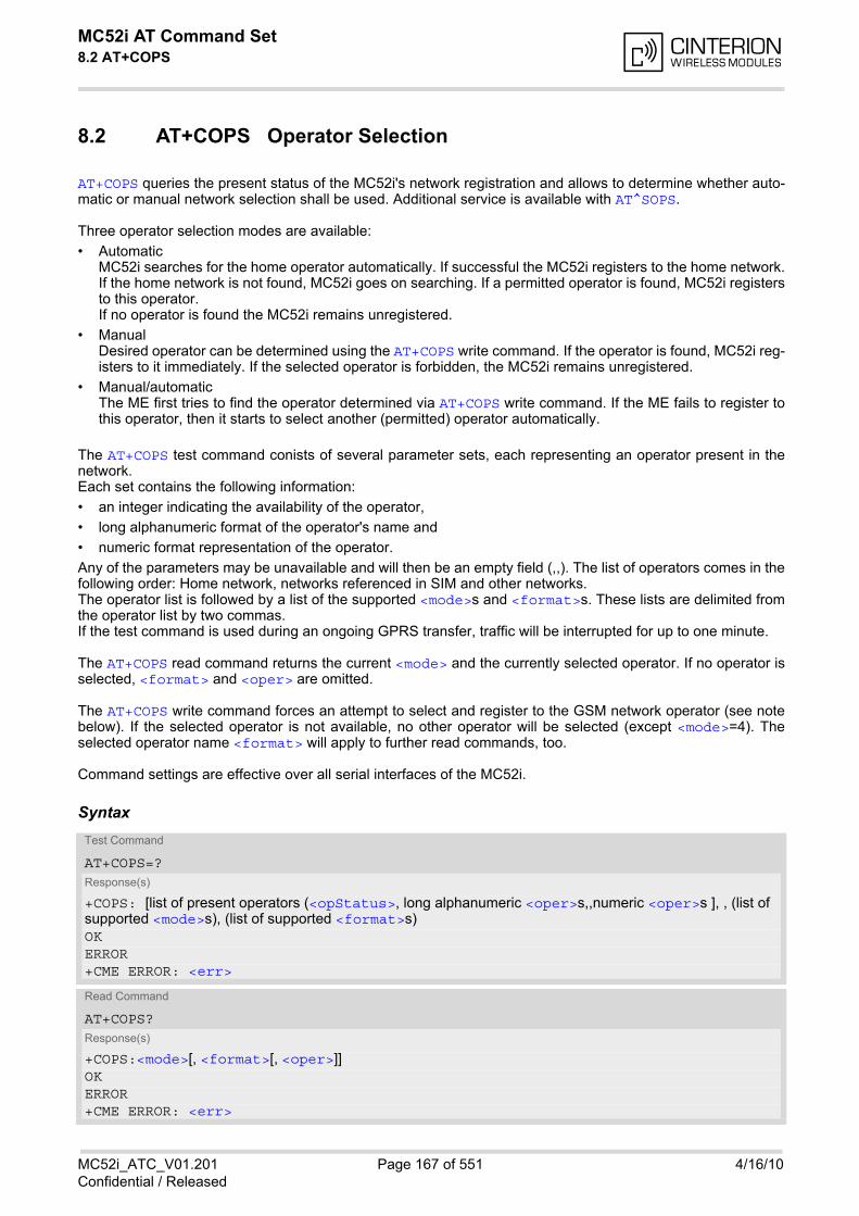
MC52i AT Command Set 8.2 AT+COPS
MC52i_ATC_V01.201 Page 167 of 551 4/16/10Confidential / Released
8.2 AT+COPS Operator Selection
AT+COPS queries the present status of the MC52i's network registration and allows to determine whether auto-matic or manual network selection shall be used. Additional service is available with AT^SOPS.
Three operator selection modes are available:
• Automatic MC52i searches for the home operator automatically. If successful the MC52i registers to the home network.If the home network is not found, MC52i goes on searching. If a permitted operator is found, MC52i registersto this operator. If no operator is found the MC52i remains unregistered.
• Manual Desired operator can be determined using the AT+COPS write command. If the operator is found, MC52i reg-isters to it immediately. If the selected operator is forbidden, the MC52i remains unregistered.
• Manual/automatic The ME first tries to find the operator determined via AT+COPS write command. If the ME fails to register tothis operator, then it starts to select another (permitted) operator automatically.
The AT+COPS test command conists of several parameter sets, each representing an operator present in thenetwork. Each set contains the following information:
• an integer indicating the availability of the operator,
• long alphanumeric format of the operator's name and
• numeric format representation of the operator.
Any of the parameters may be unavailable and will then be an empty field (,,). The list of operators comes in thefollowing order: Home network, networks referenced in SIM and other networks. The operator list is followed by a list of the supported <mode>s and <format>s. These lists are delimited fromthe operator list by two commas. If the test command is used during an ongoing GPRS transfer, traffic will be interrupted for up to one minute.
The AT+COPS read command returns the current <mode> and the currently selected operator. If no operator isselected, <format> and <oper> are omitted.
The AT+COPS write command forces an attempt to select and register to the GSM network operator (see notebelow). If the selected operator is not available, no other operator will be selected (except <mode>=4). Theselected operator name <format> will apply to further read commands, too.
Command settings are effective over all serial interfaces of the MC52i.
SyntaxTest Command
AT+COPS=?Response(s)
+COPS: [list of present operators (<opStatus>, long alphanumeric <oper>s,,numeric <oper>s ], , (list of supported <mode>s), (list of supported <format>s)OKERROR+CME ERROR: <err>
Read Command
AT+COPS?Response(s)
+COPS:<mode>[, <format>[, <oper>]]OKERROR+CME ERROR: <err>

MC52i AT Command Set 8.2 AT+COPS
MC52i_ATC_V01.201 Page 168 of 551 4/16/10Confidential / Released
Parameter Description
Status
0 Unknown
1 Operator available
2 Current operator
3 Operator forbidden
Operator
If test command: Operator name in long alphanumeric format and numeric format.If read command: Operator name as per <format>.If write command: Operator name in numeric format.
Parameter values 0 and 1 are stored non-volatile in the MC52i.
0(D) Automatic mode; <oper> field is ignored.
1 Manual operator selection Write command requires <oper> in numeric format, i.e. <format> shall be 2. Read command returns the current <mode> and the currently selected<oper>. If no operator is selected, <format> and <oper> are omitted.
2 Manually deregister from network and remain unregistered until <mode>=0 or1 or 4 is selected.
3 Set only <format> (for AT+COPS read command).
4 Automatic / manual selection; if manual selection fails, automatic mode(<mode>=0) is entered (<oper> field will be present).
0(&F) Long alphanumeric format of <oper>. Can be up to 16 characters long.
2 Numeric format of <oper>. This is the GSM Location Area Identification (LAI)number, which consists of the 3-digit Mobile Country Code (MCC) plus the 2-or 3-digit Mobile Network Code (MNC).
Write Command
AT+COPS=<mode>[, <format>[, <oper>]]Response(s)
OKERROR+CME ERROR: <err>
PIN ASC0 ASC1 MUX1 MUX2 MUX3 Charge Last Reference(s)
± + + + + + - - - GSM 07.07
<opStatus>(num)
<oper>(str)
<mode>(num)(&V)
<format>(num)(&W)(&V)
MC52i AT Command Set 8.2 AT+COPS
MC52i_ATC_V01.201 Page 169 of 551 4/16/10Confidential / Released
Note• It is not recommended to use the AT+COPS command before passing the CHV (card holder verification) / SIM
PIN1 verification. This is because after PIN1 verification the module will automatically try to register to thenetwork as though AT+COPS were 0, regardless of the settings done before with or without SIM, such asAT+COPS=2 which remains unchanged. Also, the test command should only be used after PIN1 authentica-tion.
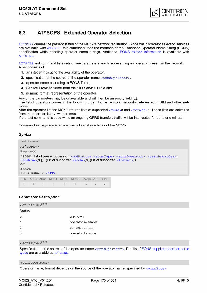
MC52i AT Command Set 8.3 AT^SOPS
MC52i_ATC_V01.201 Page 170 of 551 4/16/10Confidential / Released
8.3 AT^SOPS Extended Operator Selection
AT^SOPS queries the present status of the MC52i's network registration. Since basic operator selection servicesare available with AT+COPS this command uses the methods of the Enhanced Operator Name String (EONS)specification while handling operator name strings. Additional EONS related information is available withAT^SIND.
AT^SOPS test command lists sets of five parameters, each representing an operator present in the network. A set consists of
1. an integer indicating the availability of the operator,
2. specification of the source of the operator name <eonsOperator>,
3. operator name according to EONS Table,
4. Service Provider Name from the SIM Service Table and
5. numeric format representation of the operator.
Any of the parameters may be unavailable and will then be an empty field (,,). The list of operators comes in the following order: Home network, networks referenced in SIM and other net-works. After the operator list the MC52i returns lists of supported <mode>s and <format>s. These lists are delimitedfrom the operator list by two commas. If the test command is used while an ongoing GPRS transfer, traffic will be interrupted for up to one minute.
Command settings are effective over all serial interfaces of the MC52i.
Syntax
Parameter Description
Status
0 unknown
1 operator available
2 current operator
3 operator forbidden
Specification of the source of the operator name <eonsOperator>. Details of EONS-supplied operator nametypes are available at AT^SIND.
Operator name; format depends on the source of the operator name, specified by <eonsType>.
Test Command
AT^SOPS=?Response(s)
^SOPS:[list of present operator( <opStatus>, <eonsType>, <eonsOperator>, <servProvider>, <opName>)s ], , (list of supported <mode>)s, (list of supported <format>)sOKERROR+CME ERROR: <err>
PIN ASC0 ASC1 MUX1 MUX2 MUX3 Charge Last
+ + + + + + - - -
<opStatus>(num)
<eonsType>(num)
<eonsOperator>
MC52i AT Command Set 8.3 AT^SOPS
MC52i_ATC_V01.201 Page 171 of 551 4/16/10Confidential / Released
Service Provider Name according to setting of Service No. 17 in the SIM Service Table (EFSST).
Operator
Operator name in numerical presentation contains the GSM Location Area Identification (LAI) number, whichconsists of the 3-digit Mobile Country Code (MCC) plus the 2- or 3-digit Mobile Network Code (MNC). Parameter is stored non-volatile to the SIM.
Parameter is not applicable.
Parameter is not applicable.
Note• The AT^SOPS Test command is only accepted by the module after a valid pin has been entered.
<servProvider>(str)
<opName>
<mode>(num)
<format>(num)
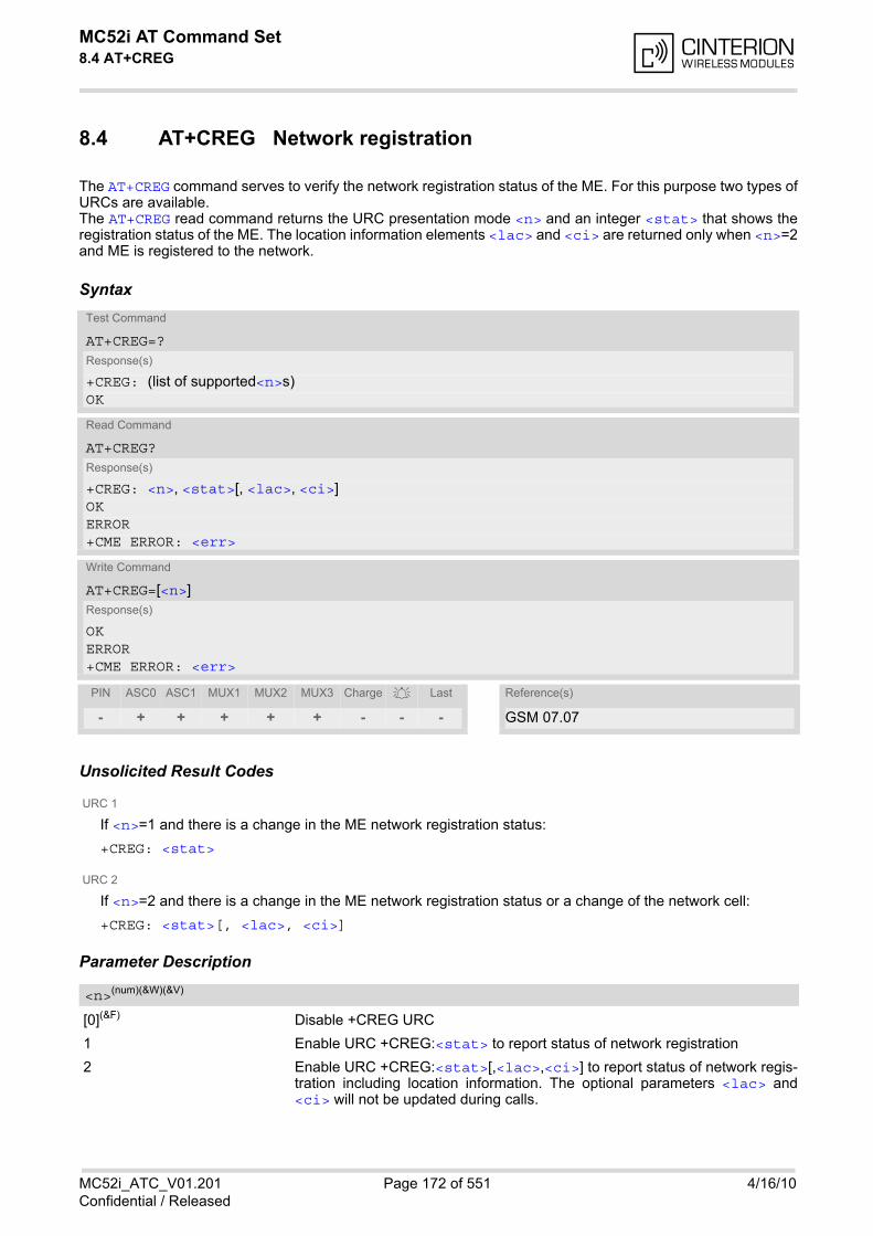
MC52i AT Command Set 8.4 AT+CREG
MC52i_ATC_V01.201 Page 172 of 551 4/16/10Confidential / Released
8.4 AT+CREG Network registration
The AT+CREG command serves to verify the network registration status of the ME. For this purpose two types ofURCs are available. The AT+CREG read command returns the URC presentation mode <n> and an integer <stat> that shows theregistration status of the ME. The location information elements <lac> and <ci> are returned only when <n>=2and ME is registered to the network.
Syntax
Unsolicited Result Codes
URC 1
If <n>=1 and there is a change in the ME network registration status:
+CREG: <stat>
URC 2
If <n>=2 and there is a change in the ME network registration status or a change of the network cell:
+CREG: <stat>[, <lac>, <ci>]
Parameter Description
[0](&F) Disable +CREG URC
1 Enable URC +CREG:<stat> to report status of network registration
2 Enable URC +CREG:<stat>[,<lac>,<ci>] to report status of network regis-tration including location information. The optional parameters <lac> and<ci> will not be updated during calls.
Test Command
AT+CREG=?Response(s)
+CREG: (list of supported<n>s)OK
Read Command
AT+CREG?Response(s)
+CREG: <n>, <stat>[, <lac>, <ci>]OKERROR+CME ERROR: <err>
Write Command
AT+CREG=[<n>]Response(s)
OKERROR+CME ERROR: <err>
PIN ASC0 ASC1 MUX1 MUX2 MUX3 Charge Last Reference(s)
- + + + + + - - - GSM 07.07
<n>(num)(&W)(&V)

MC52i AT Command Set 8.4 AT+CREG
MC52i_ATC_V01.201 Page 173 of 551 4/16/10Confidential / Released
0 Not registered, ME is currently not searching for new operatorThere is a technical problem. User intervention is required. Yet, emergencycalls can be made if any network is available. Probable causes:
• no SIM card available
• no PIN entered
• no valid Home PLMN entry found on the SIM
1 Registered to home network
2 Not registered, but ME is currently searching for a new operatorThe ME searches for an available network. Failure to log in until after more thana minute may be due to one of the following reasons:
• No network available or insufficient Rx level.
• The ME has no access rights to the networks available.
• Networks from the SIM list of allowed networks are around, but login failsdue to one of the following reasons:
- #11 ... PLMN not allowed
- #12 ... Location area not allowed
- #13 ... Roaming not allowed in this location area
After this, the search will be resumed (if automatic network search isenabled).
• The Home PLMN or an allowed PLMN is available, but login is rejected bythe cell (reasons: Access Class or LAC).
If at least one network is available, emergency calls can be made.
3 Registration denied
• If automatic network search is enabled:Authentication or registration fails after Location Update Reject due to oneof the following reasons:
- #2 ... IMSI unknown at HLR
- #3 ... Illegal MS
- #6 ... Illegal ME
Either the SIM or the MS or the ME are unable to log into any network. Userintervention is required. Emergency calls can be made, if any network isavailable.
• Only if manual network search is enabled:Manual registration fails after Location Update Reject due to the followingreasons:
- #2 ... IMSI unknown at HLR
- #3 ... Illegal MS
- #6 ... Illegal ME
- #11 ... PLMN not allowed
- #12 ... Location area not allowed
- #13 ... Roaming not allowed in this location area
No further attempt is made to search or log into a network. Emergency callscan be made if any network is available.
4 Unknown (not used)
5 Registered, roamingThe ME is registered at a foreign network (national or international network)
<stat>(num)(&V)
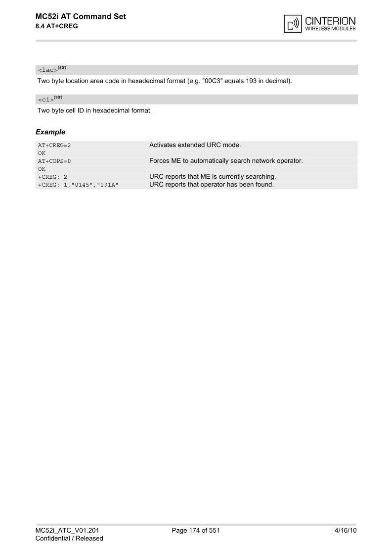
MC52i AT Command Set 8.4 AT+CREG
MC52i_ATC_V01.201 Page 174 of 551 4/16/10Confidential / Released
Two byte location area code in hexadecimal format (e.g. "00C3" equals 193 in decimal).
Two byte cell ID in hexadecimal format.
Example
<lac>(str)
<ci>(str)
AT+CREG=2 Activates extended URC mode.OKAT+COPS=0 Forces ME to automatically search network operator.OK+CREG: 2 URC reports that ME is currently searching.+CREG: 1,"0145","291A" URC reports that operator has been found.
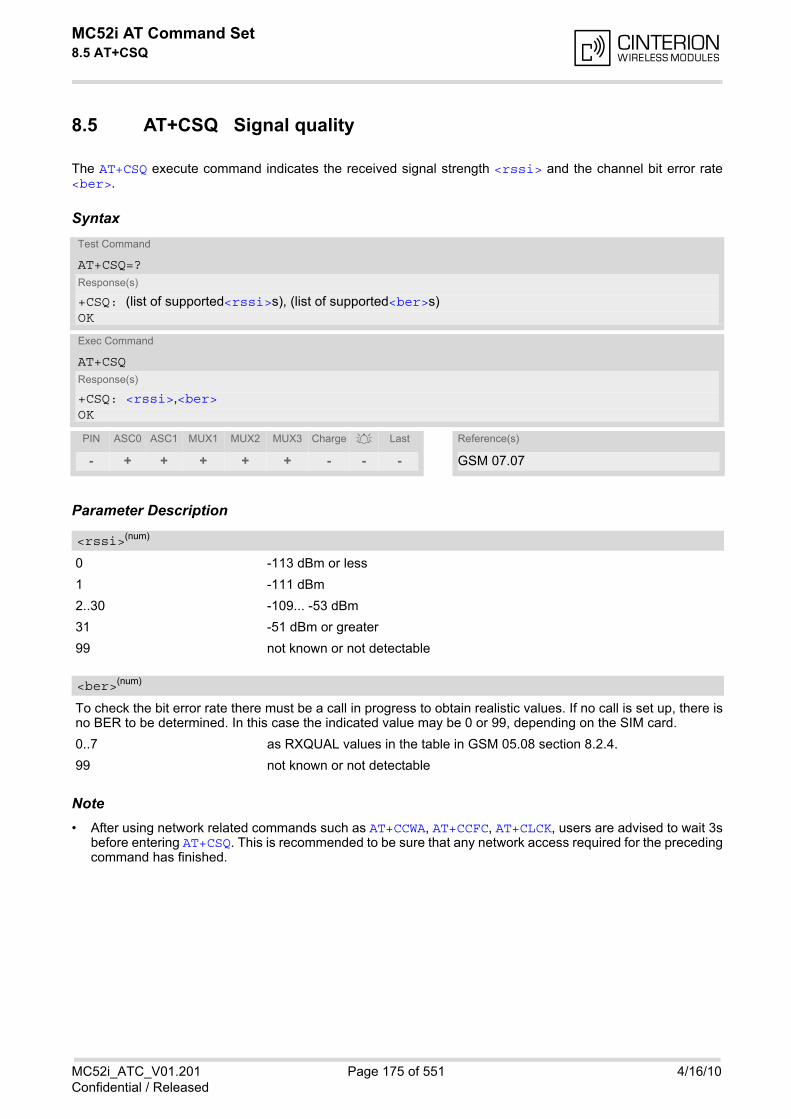
MC52i AT Command Set 8.5 AT+CSQ
MC52i_ATC_V01.201 Page 175 of 551 4/16/10Confidential / Released
8.5 AT+CSQ Signal quality
The AT+CSQ execute command indicates the received signal strength <rssi> and the channel bit error rate<ber>.
Syntax
Parameter Description
0 -113 dBm or less
1 -111 dBm
2..30 -109... -53 dBm
31 -51 dBm or greater
99 not known or not detectable
To check the bit error rate there must be a call in progress to obtain realistic values. If no call is set up, there isno BER to be determined. In this case the indicated value may be 0 or 99, depending on the SIM card.
0..7 as RXQUAL values in the table in GSM 05.08 section 8.2.4.
99 not known or not detectable
Note• After using network related commands such as AT+CCWA, AT+CCFC, AT+CLCK, users are advised to wait 3s
before entering AT+CSQ. This is recommended to be sure that any network access required for the precedingcommand has finished.
Test Command
AT+CSQ=?Response(s)
+CSQ: (list of supported<rssi>s), (list of supported<ber>s)OK
Exec Command
AT+CSQResponse(s)
+CSQ: <rssi>,<ber>OK
PIN ASC0 ASC1 MUX1 MUX2 MUX3 Charge Last Reference(s)
- + + + + + - - - GSM 07.07
<rssi>(num)
<ber>(num)
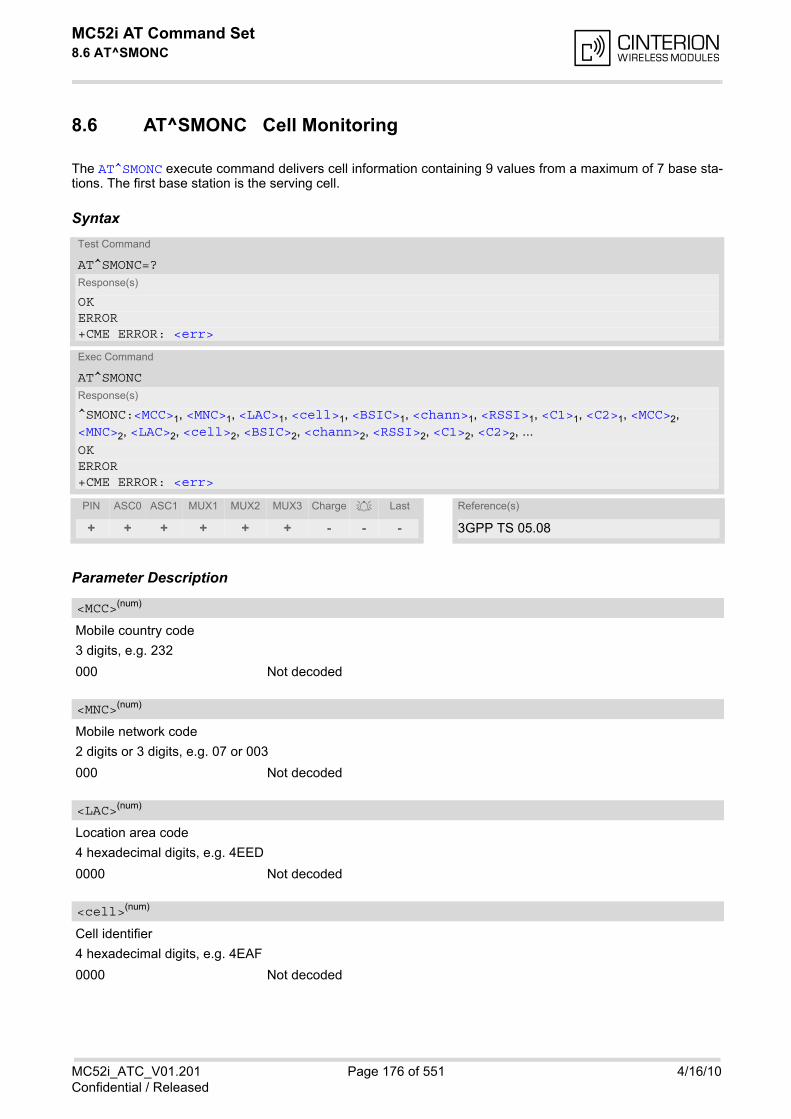
MC52i AT Command Set 8.6 AT^SMONC
MC52i_ATC_V01.201 Page 176 of 551 4/16/10Confidential / Released
8.6 AT^SMONC Cell Monitoring
The AT^SMONC execute command delivers cell information containing 9 values from a maximum of 7 base sta-tions. The first base station is the serving cell.
Syntax
Parameter Description
Mobile country code
3 digits, e.g. 232
000 Not decoded
Mobile network code
2 digits or 3 digits, e.g. 07 or 003
000 Not decoded
Location area code
4 hexadecimal digits, e.g. 4EED
0000 Not decoded
Cell identifier
4 hexadecimal digits, e.g. 4EAF
0000 Not decoded
Test Command
AT^SMONC=?Response(s)
OKERROR+CME ERROR: <err>
Exec Command
AT^SMONCResponse(s)
^SMONC:<MCC>1, <MNC>1, <LAC>1, <cell>1, <BSIC>1, <chann>1, <RSSI>1, <C1>1, <C2>1, <MCC>2, <MNC>2, <LAC>2, <cell>2, <BSIC>2, <chann>2, <RSSI>2, <C1>2, <C2>2, ...OKERROR+CME ERROR: <err>
PIN ASC0 ASC1 MUX1 MUX2 MUX3 Charge Last Reference(s)
+ + + + + + - - - 3GPP TS 05.08
<MCC>(num)
<MNC>(num)
<LAC>(num)
<cell>(num)

MC52i AT Command Set 8.6 AT^SMONC
MC52i_ATC_V01.201 Page 177 of 551 4/16/10Confidential / Released
Base station identity code
2 digits, e.g. 32
00 Not decoded
ARFCN (Absolute Frequency Channel Number)
0 Not decoded. In this case, all remaining parameters related to the same chan-nel are neither decoded. For example, a non-existing cell appears as follows:000,000,0000,0000,00,0,0,-,-
Received signal level of the BCCH carrier (0..63). The indicated value is composed of the measured value indBm plus an offset. This is in accordance with a formula specified in 3GPP TS 05.08
Coefficient for base station reselection, e.g. 30. In dedicated mode, under certain conditions the parameter can-not be updated. In such cases a '-' is presented.
Coefficient for base station reselection, e.g. 30. In dedicated mode, under certain conditions the parameter can-not be updated. In such cases a '-' is presented.
Note• To some extent, the cell monitoring commands AT^MONI, AT^MONP and AT^SMONC cover the same param-
eters. The receiving level, for example, can be queried with all three commands. Yet the resulting values maybe slightly different, even though obtained over a time period of a few seconds. This is quite normal and noth-ing to worry about, as the cell information is permanently updated.
<BSIC>(num)
<chann>(num)
<RSSI>(num)
<C1>(num)
<C2>(num)

MC52i AT Command Set 8.7 AT^SMOND
MC52i_ATC_V01.201 Page 178 of 551 4/16/10Confidential / Released
8.7 AT^SMOND Cell Monitoring
The AT^SMOND execute command can be used to obtain status information of the service cell and up to six neigh-bour cells. The advantage over other cell monitoring commands is that AT^SMOND delivers more detailed infor-mation about the received signal strength.
Syntax
Parameter Description
Serving cell information (comma-separated, no cr/lf included)
<MCC>,<MNC>,<LAC>,<cell>,<BSIC>,<chann>,<RxLev>,<RxLev>Full,<RxLev>Sub,<RxQual>,<RxQual>Full,<RxQual>Sub,<Timeslot>If no serving cell is found, unavailable values are omitted:" ,,,,,,<RxLev>,,,0,,,0"
Neighbour cell information for neighbour cell 1 through 6 (comma-separated, no cr/lf included)
<MCC>1,<MNC>1,<LAC>1,<cell>1,<BSIC>1,<chann>1,<RxLev>1, (these parameters repeated for neighbourcells 2 through 6 with no CR/LF): ... <MCC>6,<MNC>6,<LAC>6,<cell>6,<BSIC>6,<chann>6,<RxLev>6 An unavailable cell appears as follows: " ,,,,,,0"
Values for RSSI and BER (comma-separated, no cr/lf included)
<RSSI>,<BER>
Mobile country code
3 digits, e.g. 232
000 Not decoded
Test Command
AT^SMOND=?Response(s)
OKERROR+CME ERROR: <err>
Exec Command
AT^SMONDResponse(s)
^SMOND:[<sci>][, <nci>][, <TA>][, <rssiber>]OKERROR+CME ERROR: <err>
PIN ASC0 ASC1 MUX1 MUX2 MUX3 Charge Last Reference(s)
+ + + + + + - - - 3GPP TS 05.08
<sci>(str)
<nci>(str)
<rssiber>(str)
<MCC>(num)
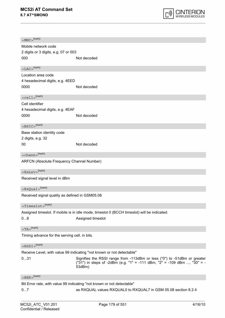
MC52i AT Command Set 8.7 AT^SMOND
MC52i_ATC_V01.201 Page 179 of 551 4/16/10Confidential / Released
Mobile network code
2 digits or 3 digits, e.g. 07 or 003
000 Not decoded
Location area code
4 hexadecimal digits, e.g. 4EED
0000 Not decoded
Cell identifier
4 hexadecimal digits, e.g. 4EAF
0000 Not decoded
Base station identity code
2 digits, e.g. 32
00 Not decoded
ARFCN (Absolute Frequency Channel Number)
Received signal level in dBm
Received signal quality as defined in GSM05.08
Assigned timeslot. If mobile is in idle mode, timeslot 0 (BCCH timeslot) will be indicated.
0...8 Assigned timeslot
Timing advance for the serving cell, in bits.
Receive Level, with value 99 indicating "not known or not detectable"
0...31 Signifies the RSSI range from -113dBm or less ("0") to -51dBm or greater("31") in steps of -2dBm (e.g. "1" = -111 dBm, "2" = -109 dBm ..., "30" = -53dBm)
Bit Error rate, with value 99 indicating "not known or not detectable"
0...7 as RXQUAL values RXQUAL0 to RXQUAL7 in GSM 05.08 section 8.2.4
<MNC>(num)
<LAC>(num)
<cell>(num)
<BSIC>(num)
<chann>(num)
<RxLev>(num)
<RxQual>(num)
<Timeslot>(num)
<TA>(num)
<RSSI>(num)
<BER>(num)

MC52i AT Command Set 8.7 AT^SMOND
MC52i_ATC_V01.201 Page 180 of 551 4/16/10Confidential / Released
Notes• To some extent, the cell monitoring commands AT^SMOND, AT^MONI, AT^MONP and AT^SMONC cover the
same parameters. The receiving level, for example, can be queried with all three commands. Yet the resultingvalues may be slightly different, even though obtained over a time period of a few seconds. This is quite nor-mal and nothing to worry about, as the cell information is permanently updated.
• During a connection, not all of the neighbour cell information can be decoded. The following restrictions apply:
- Information is updated only for neighbour cells that have already been visible at connection setup, andcontinue to be included in the list of cells.
- New neighbour cells added to the list, for example after handover, cannot be displayed until the connectionis released.
Example
at^smond Execute command ^SMOND:262,01,3008,6060,32,100,66,,,0,,,0,262,01,3008,DDD1,35,92,80,262,01,3008,,31,96,83,262,01,3008,BFBE,35,27,86,262,01,3008,,32,98,88,262,01,3008,BB44,32,90,89,262,01,3008,8307,31,22,93,2,23,99
Line breaks inserted for readability in print
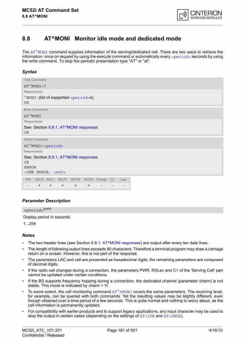
MC52i AT Command Set 8.8 AT^MONI
MC52i_ATC_V01.201 Page 181 of 551 4/16/10Confidential / Released
8.8 AT^MONI Monitor idle mode and dedicated mode
The AT^MONI command supplies information of the serving/dedicated cell. There are two ways to retrieve theinformation: once on request by using the execute command or automatically every <period> seconds by usingthe write command. To stop the periodic presentation type "AT" or "at".
Syntax
Parameter Description
Display period in seconds
1...254
Notes• The two header lines (see Section 8.8.1, AT^MONI responses) are output after every ten data lines.
• The length of following output lines exceeds 80 characters. Therefore a terminal program may draw a carriagereturn on a screen. However, this is not part of the response.
• The parameters LAC and cell are presented as hexadecimal digits, the remaining parameters are composedof decimal digits.
• If the radio cell changes during a connection, the parameters PWR, RXLev and C1 of the 'Serving Cell' partcannot be updated under certain conditions.
• If the BS supports frequency hopping during a connection, the dedicated channel (parameter chann) is notstable. This mode is indicated by chann = 'h'.
• To some extent, the cell monitoring command AT^SMONC covers the same parameters. The receiving level,for example, can be queried with both commands. Yet the resulting values may be slightly different, eventhough obtained over a time period of a few seconds. This is quite normal and nothing to worry about, as thecell information is permanently updated.
• For compatibility with earlier products and to support legacy applications, any input character may be used tostop the output in certain cases (depending on the settings of AT+IPR and AT+CMUX).
Test Command
AT^MONI=?Response(s)
^MONI:(list of supported <period>s)OK
Exec Command
AT^MONIResponse(s)
See: Section 8.8.1, AT^MONI responsesOK
Write Command
AT^MONI=<period>Response(s)
See: Section 8.8.1, AT^MONI responsesOKERROR+CME ERROR: <err>
PIN ASC0 ASC1 MUX1 MUX2 MUX3 Charge Last
- + + + + + - - -
<period>(num)

MC52i AT Command Set 8.8 AT^MONI
MC52i_ATC_V01.201 Page 182 of 551 4/16/10Confidential / Released
8.8.1 AT^MONI responses
ME is not connected:a) ME is camping on a cell and registered to the network:
b) ME is camping on a cell but not registered to the network (only emergency call allowed):
c) ME camping on a cell, but searching for a better cell (cell reselection):
d) ME is searching and could not (yet) find a suitable cell:
ME is connected (Call in progress):
Columns for Serving Cell:
Columns for Dedicated channel:
Serving Cell I Dedicated channelchann rs dBm MCC MNC LAC cell NCC BCC PWR RXLev C1 I chann TS timAdv PWR dBm Q ChMod1013 21 -71 001 01 1001 0103 7 7 33 -105 33 I No connection
Serving Cell I Dedicated channelchann rs dBm MCC MNC LAC cell NCC BCC PWR RXLev C1 I chann TS timAdv PWR dBm Q ChMod1013 21 -71 001 01 1001 0103 7 7 33 -105 33 I Limited Service
Serving Cell I Dedicated channelchann rs dBm MCC MNC LAC cell NCC BCC PWR RXLev C1 I chann TS timAdv PWR dBm Q ChMod1013 21 -71 001 01 1001 0103 7 7 33 -105 33 I Cell Reselection
Serving Cell I Dedicated channelchann rs dBm MCC MNC LAC cell NCC BCC PWR RXLev C1 I chann TS timAdv PWR dBm Q ChModSearching
Serving Cell I Dedicated channelchann rs dBm MCC MNC LAC cell NCC BCC PWR RXLev C1 I chann TS timAdv PWR dBm Q ChMod1013 19 -76 001 01 1001 0103 7 7 33 -105 33 I 1015 1 0 5 -76 0 S_HR
Column Description
chann ARFCN (Absolute Frequency Channel Number) of the BCCH carrier
rs RSSI value 0 - 63 (RSSI = Received signal strength indication)
dBm Receiving level of the BCCH carrier in dBm
MCC Mobile Country Code (first part of the PLMN code)
MNC Mobile Network Code (second part of the PLMN code)
LAC Location area code, see note
cell Cell ID
NCC PLMN colour code
BCC Base station colour code
PWR Maximal power level used on RACH channel in dBm
RXLev Minimal receiving level (in dBm) to allow registration
C1 Coefficient for base station selection
Column Description
chann ARFCN (Absolute Frequency Channel Number) of the TCH carrierNote: <chann> = h indicates frequency hopping.
TS Timeslot number
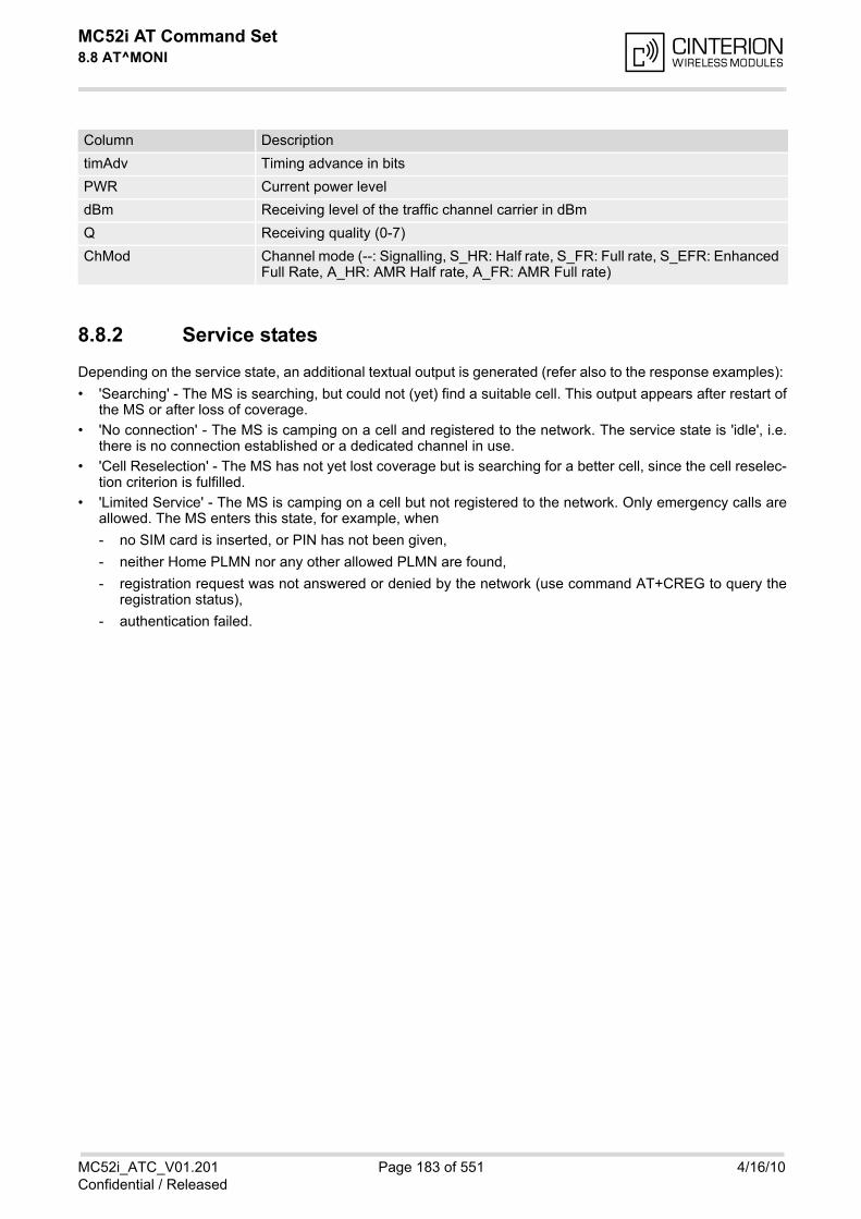
MC52i AT Command Set 8.8 AT^MONI
MC52i_ATC_V01.201 Page 183 of 551 4/16/10Confidential / Released
8.8.2 Service states
Depending on the service state, an additional textual output is generated (refer also to the response examples):
• 'Searching' - The MS is searching, but could not (yet) find a suitable cell. This output appears after restart ofthe MS or after loss of coverage.
• 'No connection' - The MS is camping on a cell and registered to the network. The service state is 'idle', i.e.there is no connection established or a dedicated channel in use.
• 'Cell Reselection' - The MS has not yet lost coverage but is searching for a better cell, since the cell reselec-tion criterion is fulfilled.
• 'Limited Service' - The MS is camping on a cell but not registered to the network. Only emergency calls areallowed. The MS enters this state, for example, when
- no SIM card is inserted, or PIN has not been given,
- neither Home PLMN nor any other allowed PLMN are found,
- registration request was not answered or denied by the network (use command AT+CREG to query theregistration status),
- authentication failed.
timAdv Timing advance in bits
PWR Current power level
dBm Receiving level of the traffic channel carrier in dBm
Q Receiving quality (0-7)
ChMod Channel mode (--: Signalling, S_HR: Half rate, S_FR: Full rate, S_EFR: Enhanced Full Rate, A_HR: AMR Half rate, A_FR: AMR Full rate)
Column Description
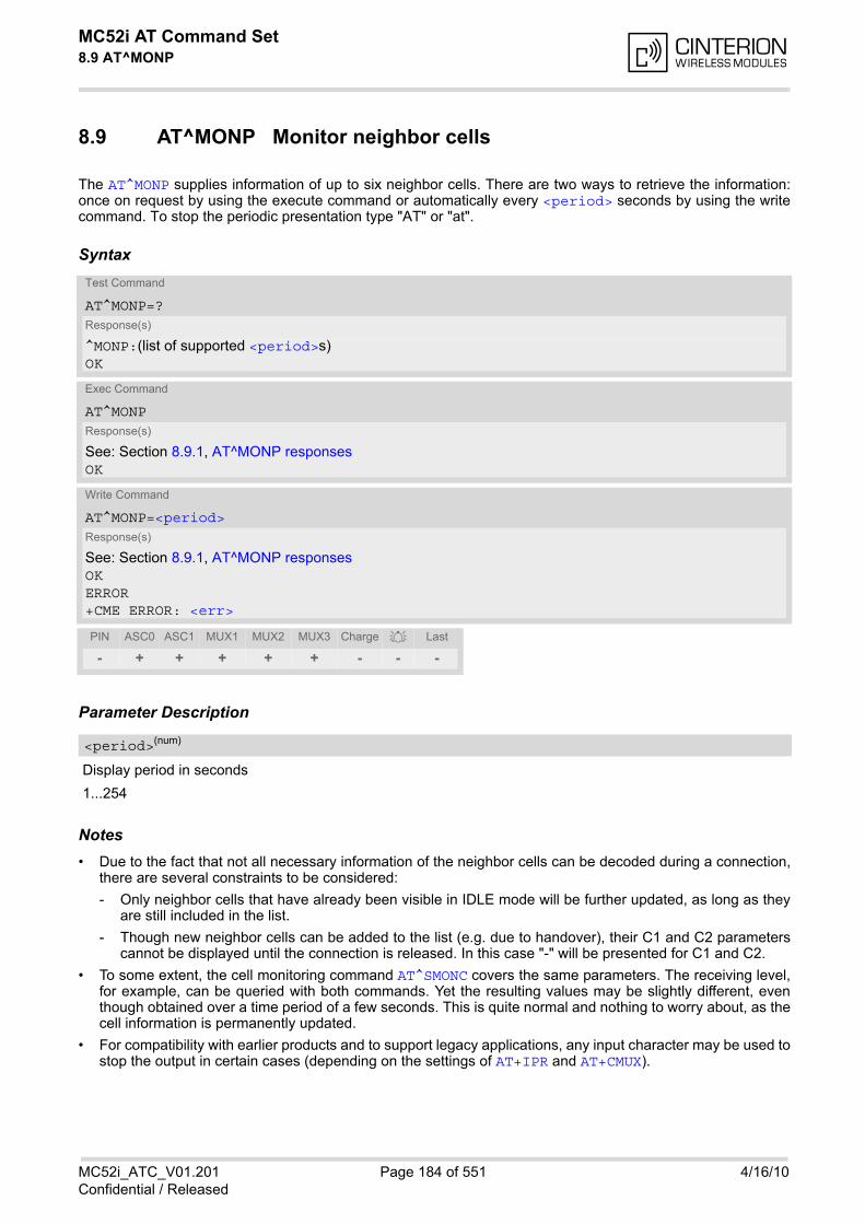
MC52i AT Command Set 8.9 AT^MONP
MC52i_ATC_V01.201 Page 184 of 551 4/16/10Confidential / Released
8.9 AT^MONP Monitor neighbor cells
The AT^MONP supplies information of up to six neighbor cells. There are two ways to retrieve the information:once on request by using the execute command or automatically every <period> seconds by using the writecommand. To stop the periodic presentation type "AT" or "at".
Syntax
Parameter Description
Display period in seconds
1...254
Notes• Due to the fact that not all necessary information of the neighbor cells can be decoded during a connection,
there are several constraints to be considered:
- Only neighbor cells that have already been visible in IDLE mode will be further updated, as long as theyare still included in the list.
- Though new neighbor cells can be added to the list (e.g. due to handover), their C1 and C2 parameterscannot be displayed until the connection is released. In this case "-" will be presented for C1 and C2.
• To some extent, the cell monitoring command AT^SMONC covers the same parameters. The receiving level,for example, can be queried with both commands. Yet the resulting values may be slightly different, eventhough obtained over a time period of a few seconds. This is quite normal and nothing to worry about, as thecell information is permanently updated.
• For compatibility with earlier products and to support legacy applications, any input character may be used tostop the output in certain cases (depending on the settings of AT+IPR and AT+CMUX).
Test Command
AT^MONP=?Response(s)
^MONP:(list of supported <period>s)OK
Exec Command
AT^MONPResponse(s)
See: Section 8.9.1, AT^MONP responsesOK
Write Command
AT^MONP=<period>Response(s)
See: Section 8.9.1, AT^MONP responsesOKERROR+CME ERROR: <err>
PIN ASC0 ASC1 MUX1 MUX2 MUX3 Charge Last
- + + + + + - - -
<period>(num)
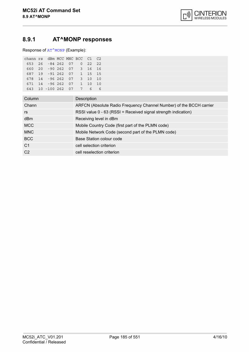
MC52i AT Command Set 8.9 AT^MONP
MC52i_ATC_V01.201 Page 185 of 551 4/16/10Confidential / Released
8.9.1 AT^MONP responses
Response of AT^MONP (Example):
chann rs dBm MCC MNC BCC C1 C2 653 26 -84 262 07 0 22 22 660 20 -90 262 07 3 16 16 687 19 -91 262 07 1 15 15 678 14 -96 262 07 3 10 10 671 14 -96 262 07 1 10 10 643 10 -100 262 07 7 6 6
Column Description
Chann ARFCN (Absolute Radio Frequency Channel Number) of the BCCH carrier
rs RSSI value 0 - 63 (RSSI = Received signal strength indication)
dBm Receiving level in dBm
MCC Mobile Country Code (first part of the PLMN code)
MNC Mobile Network Code (second part of the PLMN code)
BCC Base Station colour code
C1 cell selection criterion
C2 cell reselection criterion
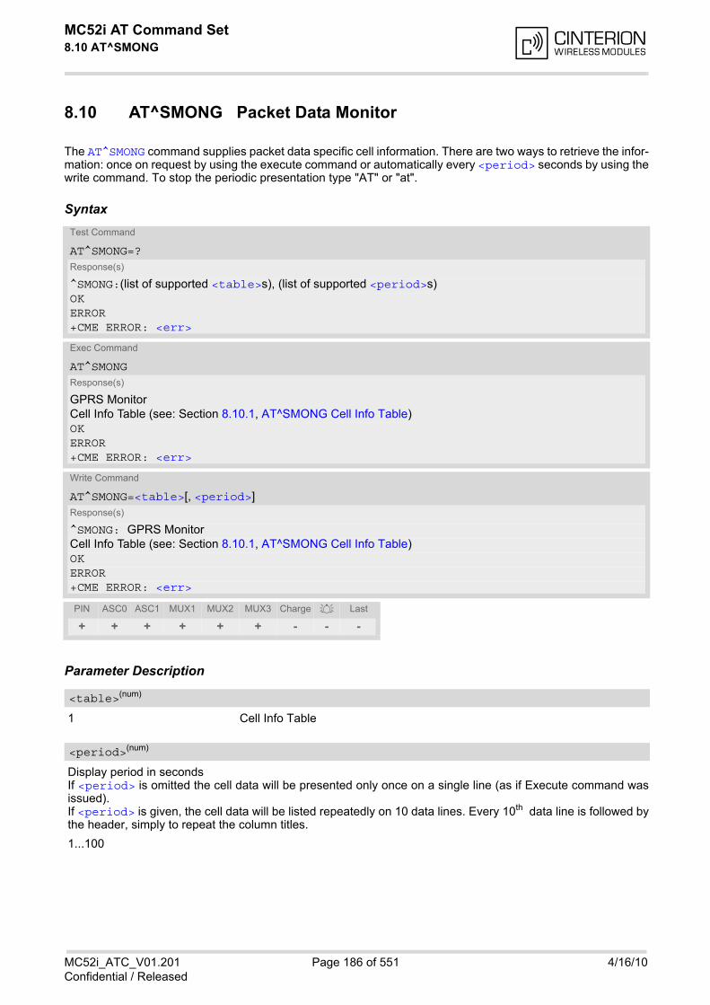
MC52i AT Command Set 8.10 AT^SMONG
MC52i_ATC_V01.201 Page 186 of 551 4/16/10Confidential / Released
8.10 AT^SMONG Packet Data Monitor
The AT^SMONG command supplies packet data specific cell information. There are two ways to retrieve the infor-mation: once on request by using the execute command or automatically every <period> seconds by using thewrite command. To stop the periodic presentation type "AT" or "at".
Syntax
Parameter Description
1 Cell Info Table
Display period in secondsIf <period> is omitted the cell data will be presented only once on a single line (as if Execute command wasissued).If <period> is given, the cell data will be listed repeatedly on 10 data lines. Every 10th data line is followed bythe header, simply to repeat the column titles.
1...100
Test Command
AT^SMONG=?Response(s)
^SMONG:(list of supported <table>s), (list of supported <period>s)OKERROR+CME ERROR: <err>
Exec Command
AT^SMONGResponse(s)
GPRS MonitorCell Info Table (see: Section 8.10.1, AT^SMONG Cell Info Table)OKERROR+CME ERROR: <err>
Write Command
AT^SMONG=<table>[, <period>]Response(s)
^SMONG: GPRS MonitorCell Info Table (see: Section 8.10.1, AT^SMONG Cell Info Table)OKERROR+CME ERROR: <err>
PIN ASC0 ASC1 MUX1 MUX2 MUX3 Charge Last
+ + + + + + - - -
<table>(num)
<period>(num)
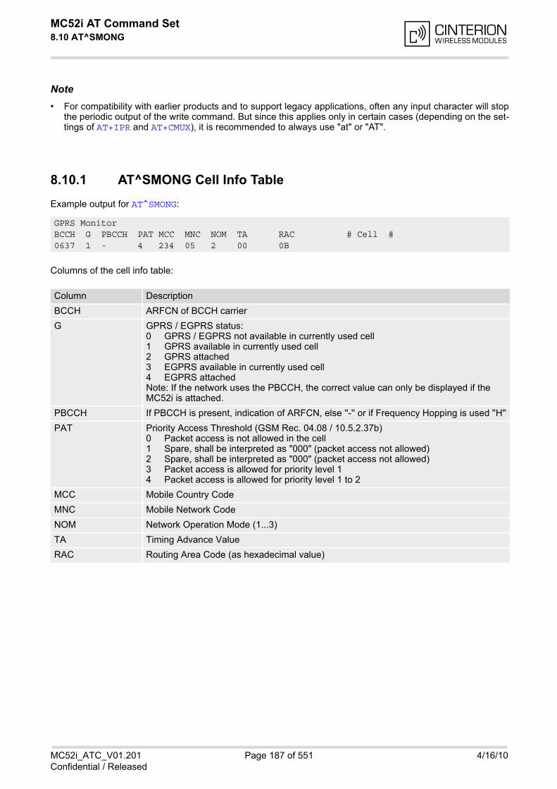
MC52i AT Command Set 8.10 AT^SMONG
MC52i_ATC_V01.201 Page 187 of 551 4/16/10Confidential / Released
Note• For compatibility with earlier products and to support legacy applications, often any input character will stop
the periodic output of the write command. But since this applies only in certain cases (depending on the set-tings of AT+IPR and AT+CMUX), it is recommended to always use "at" or "AT".
8.10.1 AT^SMONG Cell Info Table
Example output for AT^SMONG:
Columns of the cell info table:
GPRS MonitorBCCH G PBCCH PAT MCC MNC NOM TA RAC # Cell #0637 1 - 4 234 05 2 00 0B
Column Description
BCCH ARFCN of BCCH carrier
G GPRS / EGPRS status:0 GPRS / EGPRS not available in currently used cell1 GPRS available in currently used cell2 GPRS attached3 EGPRS available in currently used cell4 EGPRS attachedNote: If the network uses the PBCCH, the correct value can only be displayed if the MC52i is attached.
PBCCH If PBCCH is present, indication of ARFCN, else ''-'' or if Frequency Hopping is used ''H''
PAT Priority Access Threshold (GSM Rec. 04.08 / 10.5.2.37b)0 Packet access is not allowed in the cell1 Spare, shall be interpreted as "000" (packet access not allowed)2 Spare, shall be interpreted as "000" (packet access not allowed)3 Packet access is allowed for priority level 14 Packet access is allowed for priority level 1 to 2
MCC Mobile Country Code
MNC Mobile Network Code
NOM Network Operation Mode (1...3)
TA Timing Advance Value
RAC Routing Area Code (as hexadecimal value)

MC52i AT Command Set 8.11 AT^SALS
MC52i_ATC_V01.201 Page 188 of 551 4/16/10Confidential / Released
8.11 AT^SALS Alternate Line Service
The AT^SALS command is designed to support Alternate Line Service. This allows the subscriber to use twovoice numbers on the same SIM card (service requires a dual line SIM card). The write command enables or disables the presentation of <view> and specifies the <line> used for outgoingcalls. The read command returns the presentation mode of <view> and the currently selected <line>.
Syntax
Unsolicited Result CodeIf switched on with <view>=1:
^SALS: <line>
Indicates the line used by an incoming call.
Parameter Description
Controls the presentation mode of the URC "^SALS" which indicates the line number used by an incoming call:
0(&F)(P) Disables indication of the called line
1 Enables indication of the called line
Selects the line to be used for outgoing calls. Setting is global for the ME and non volatile.
1(&F)(D) ALS Line 1
2 ALS Line 2
Note• If a non ALS SIM is inserted, the <line> will be reset to line 1.
Test Command
AT^SALS=?Response(s)
^SALS:(list of supported <view>s), (list of supported <line>s)OK
Read Command
AT^SALS?Response(s)
^SALS: <view>, <line>OKERROR
Write Command
AT^SALS=<view>[, <line>]Response(s)
OKERROR
PIN ASC0 ASC1 MUX1 MUX2 MUX3 Charge Last
+ + + + + + - - -
<view>(num)
<line>(num)

MC52i AT Command Set 8.11 AT^SALS
MC52i_ATC_V01.201 Page 189 of 551 4/16/10Confidential / Released
Example
AT^SALS=1,1 Line 1 has been selected for outgoing calls. "^SALS" URC is enabled.RING You receive a notification that you have an incoming call on line 2.^SALS: 2
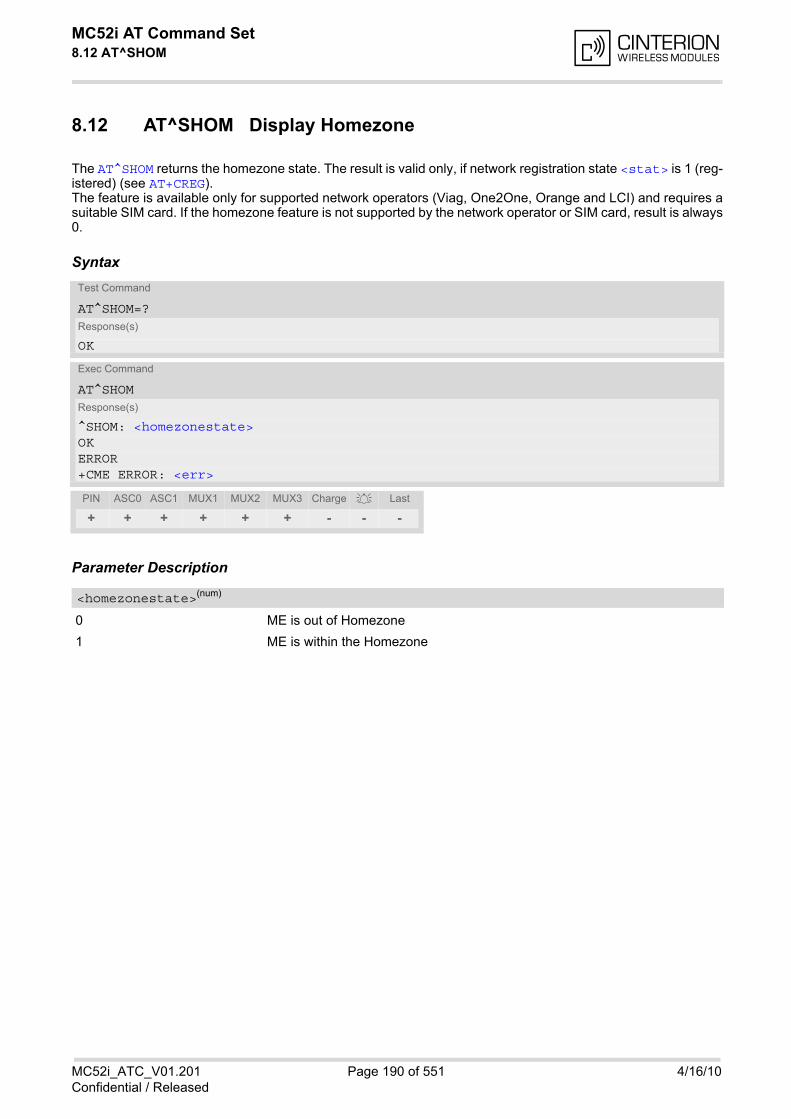
MC52i AT Command Set 8.12 AT^SHOM
MC52i_ATC_V01.201 Page 190 of 551 4/16/10Confidential / Released
8.12 AT^SHOM Display Homezone
The AT^SHOM returns the homezone state. The result is valid only, if network registration state <stat> is 1 (reg-istered) (see AT+CREG). The feature is available only for supported network operators (Viag, One2One, Orange and LCI) and requires asuitable SIM card. If the homezone feature is not supported by the network operator or SIM card, result is always0.
Syntax
Parameter Description
0 ME is out of Homezone
1 ME is within the Homezone
Test Command
AT^SHOM=?Response(s)
OK
Exec Command
AT^SHOMResponse(s)
^SHOM: <homezonestate>OKERROR+CME ERROR: <err>
PIN ASC0 ASC1 MUX1 MUX2 MUX3 Charge Last
+ + + + + + - - -
<homezonestate>(num)
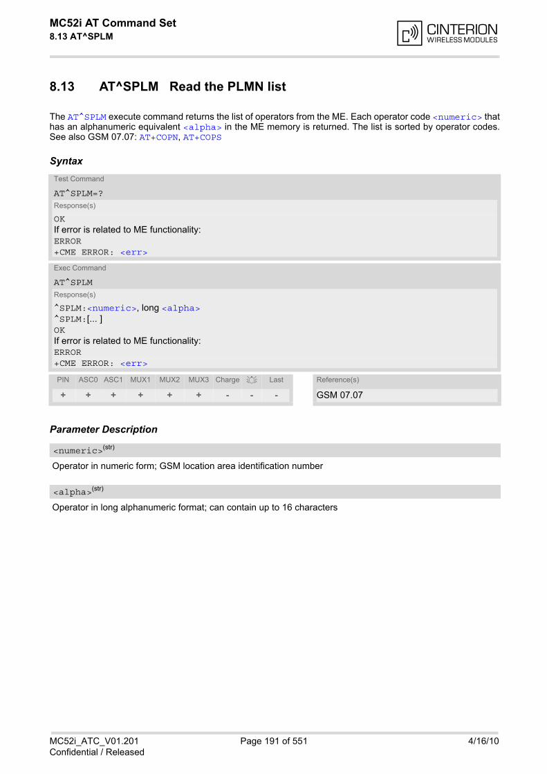
MC52i AT Command Set 8.13 AT^SPLM
MC52i_ATC_V01.201 Page 191 of 551 4/16/10Confidential / Released
8.13 AT^SPLM Read the PLMN list
The AT^SPLM execute command returns the list of operators from the ME. Each operator code <numeric> thathas an alphanumeric equivalent <alpha> in the ME memory is returned. The list is sorted by operator codes.See also GSM 07.07: AT+COPN, AT+COPS
Syntax
Parameter Description
Operator in numeric form; GSM location area identification number
Operator in long alphanumeric format; can contain up to 16 characters
Test Command
AT^SPLM=?Response(s)
OKIf error is related to ME functionality:ERROR+CME ERROR: <err>
Exec Command
AT^SPLMResponse(s)
^SPLM:<numeric>, long <alpha>^SPLM:[... ]OKIf error is related to ME functionality:ERROR+CME ERROR: <err>
PIN ASC0 ASC1 MUX1 MUX2 MUX3 Charge Last Reference(s)
+ + + + + + - - - GSM 07.07
<numeric>(str)
<alpha>(str)
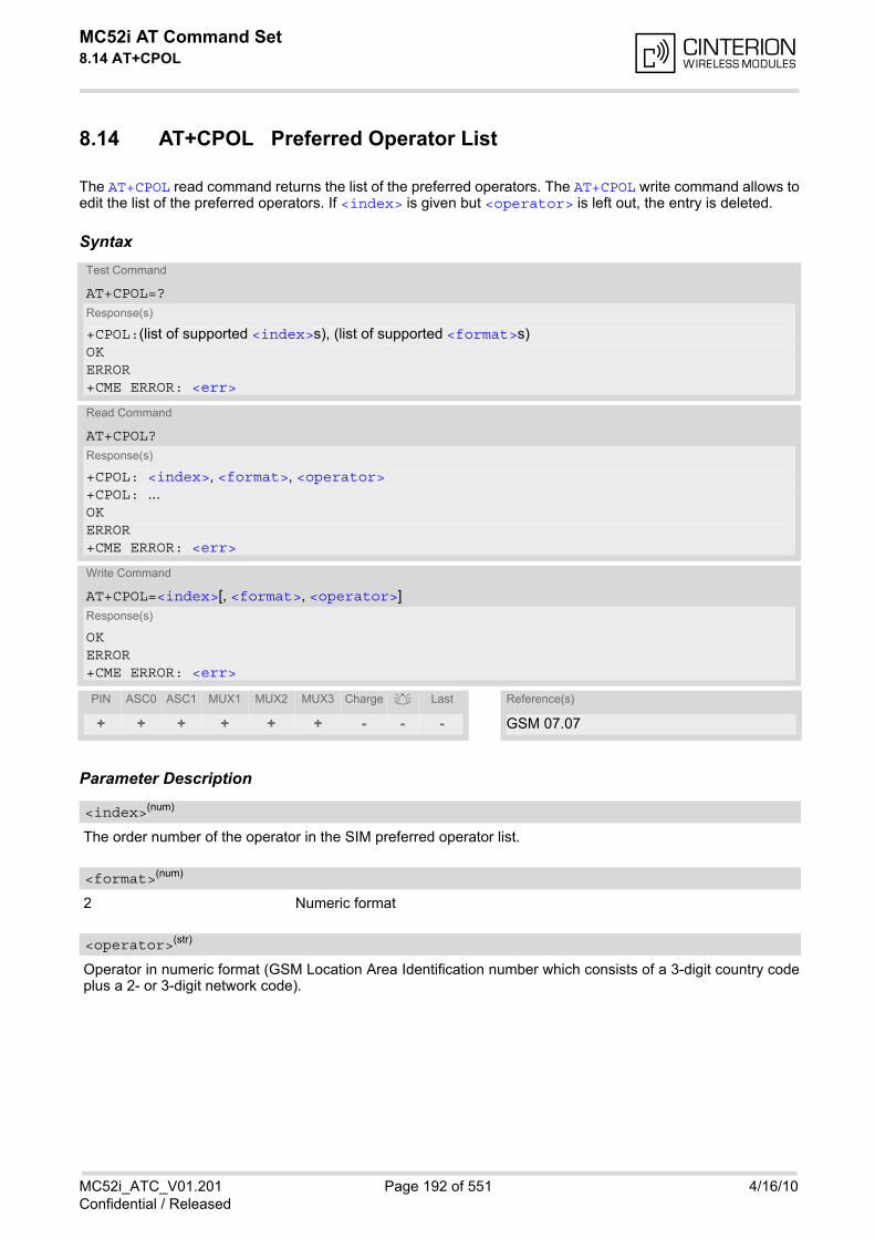
MC52i AT Command Set 8.14 AT+CPOL
MC52i_ATC_V01.201 Page 192 of 551 4/16/10Confidential / Released
8.14 AT+CPOL Preferred Operator List
The AT+CPOL read command returns the list of the preferred operators. The AT+CPOL write command allows toedit the list of the preferred operators. If <index> is given but <operator> is left out, the entry is deleted.
Syntax
Parameter Description
The order number of the operator in the SIM preferred operator list.
2 Numeric format
Operator in numeric format (GSM Location Area Identification number which consists of a 3-digit country codeplus a 2- or 3-digit network code).
Test Command
AT+CPOL=?Response(s)
+CPOL:(list of supported <index>s), (list of supported <format>s)OKERROR+CME ERROR: <err>
Read Command
AT+CPOL?Response(s)
+CPOL: <index>, <format>, <operator>+CPOL: ...OKERROR+CME ERROR: <err>
Write Command
AT+CPOL=<index>[, <format>, <operator>]Response(s)
OKERROR+CME ERROR: <err>
PIN ASC0 ASC1 MUX1 MUX2 MUX3 Charge Last Reference(s)
+ + + + + + - - - GSM 07.07
<index>(num)
<format>(num)
<operator>(str)
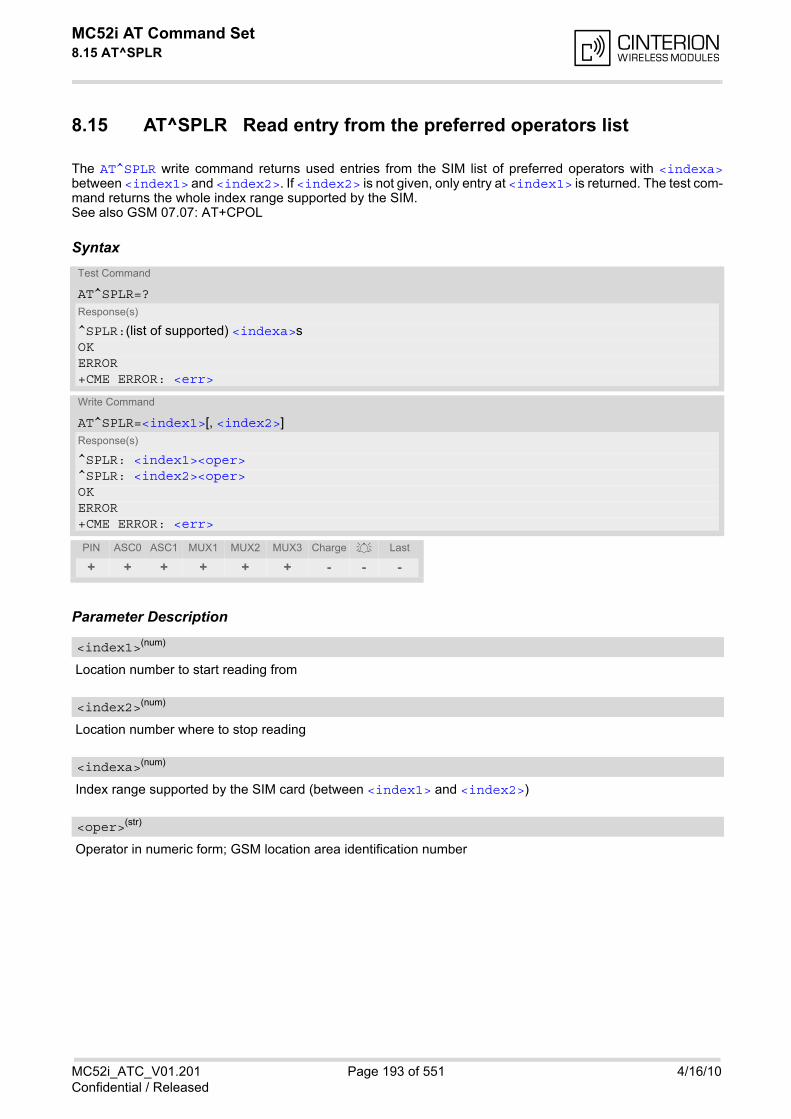
MC52i AT Command Set 8.15 AT^SPLR
MC52i_ATC_V01.201 Page 193 of 551 4/16/10Confidential / Released
8.15 AT^SPLR Read entry from the preferred operators list
The AT^SPLR write command returns used entries from the SIM list of preferred operators with <indexa>between <index1> and <index2>. If <index2> is not given, only entry at <index1> is returned. The test com-mand returns the whole index range supported by the SIM.See also GSM 07.07: AT+CPOL
Syntax
Parameter Description
Location number to start reading from
Location number where to stop reading
Index range supported by the SIM card (between <index1> and <index2>)
Operator in numeric form; GSM location area identification number
Test Command
AT^SPLR=?Response(s)
^SPLR:(list of supported) <indexa>s OKERROR+CME ERROR: <err>
Write Command
AT^SPLR=<index1>[, <index2>]Response(s)
^SPLR: <index1><oper>^SPLR: <index2><oper>OKERROR+CME ERROR: <err>
PIN ASC0 ASC1 MUX1 MUX2 MUX3 Charge Last
+ + + + + + - - -
<index1>(num)
<index2>(num)
<indexa>(num)
<oper>(str)
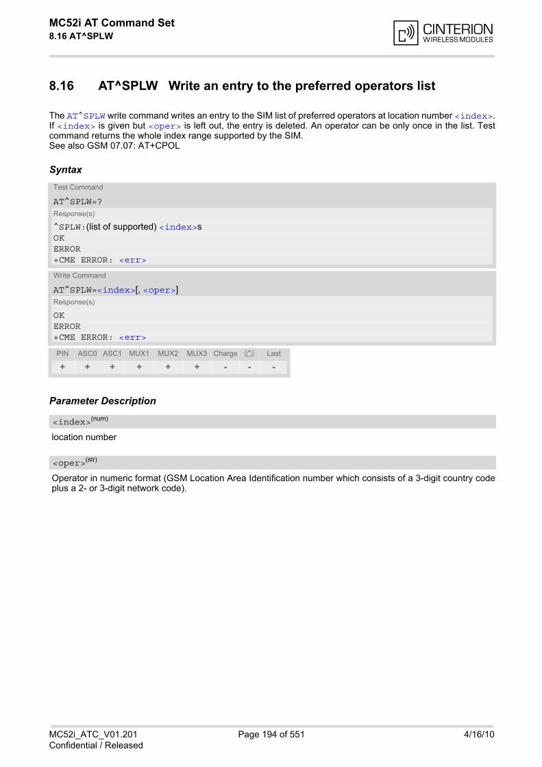
MC52i AT Command Set 8.16 AT^SPLW
MC52i_ATC_V01.201 Page 194 of 551 4/16/10Confidential / Released
8.16 AT^SPLW Write an entry to the preferred operators list
The AT^SPLW write command writes an entry to the SIM list of preferred operators at location number <index>.If <index> is given but <oper> is left out, the entry is deleted. An operator can be only once in the list. Testcommand returns the whole index range supported by the SIM.See also GSM 07.07: AT+CPOL
Syntax
Parameter Description
location number
Operator in numeric format (GSM Location Area Identification number which consists of a 3-digit country codeplus a 2- or 3-digit network code).
Test Command
AT^SPLW=?Response(s)
^SPLW:(list of supported) <index>s OKERROR+CME ERROR: <err>
Write Command
AT^SPLW=<index>[, <oper>]Response(s)
OKERROR+CME ERROR: <err>
PIN ASC0 ASC1 MUX1 MUX2 MUX3 Charge Last
+ + + + + + - - -
<index>(num)
<oper>(str)
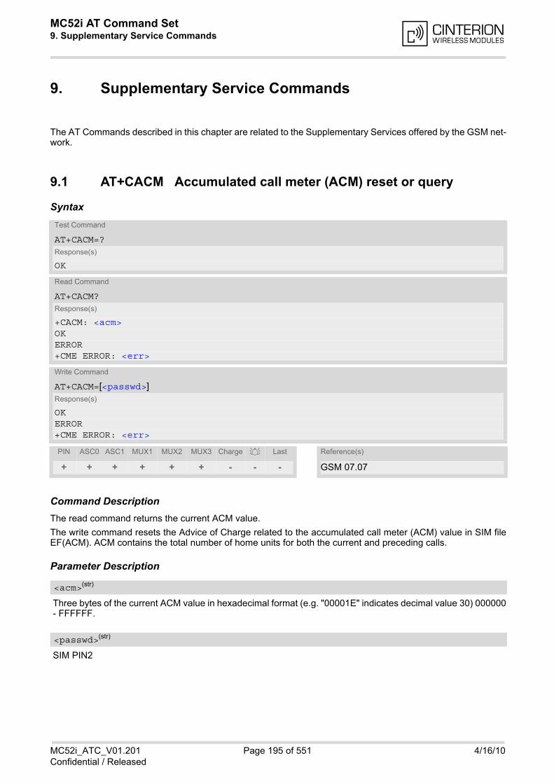
MC52i AT Command Set 9. Supplementary Service Commands
MC52i_ATC_V01.201 Page 195 of 551 4/16/10Confidential / Released
9. Supplementary Service Commands
The AT Commands described in this chapter are related to the Supplementary Services offered by the GSM net-work.
9.1 AT+CACM Accumulated call meter (ACM) reset or query
Syntax
Command DescriptionThe read command returns the current ACM value.
The write command resets the Advice of Charge related to the accumulated call meter (ACM) value in SIM fileEF(ACM). ACM contains the total number of home units for both the current and preceding calls.
Parameter Description
Three bytes of the current ACM value in hexadecimal format (e.g. "00001E" indicates decimal value 30) 000000- FFFFFF.
SIM PIN2
Test Command
AT+CACM=?Response(s)
OK
Read Command
AT+CACM?Response(s)
+CACM: <acm>OKERROR+CME ERROR: <err>
Write Command
AT+CACM=[<passwd>]Response(s)
OKERROR+CME ERROR: <err>
PIN ASC0 ASC1 MUX1 MUX2 MUX3 Charge Last Reference(s)
+ + + + + + - - - GSM 07.07
<acm>(str)
<passwd>(str)
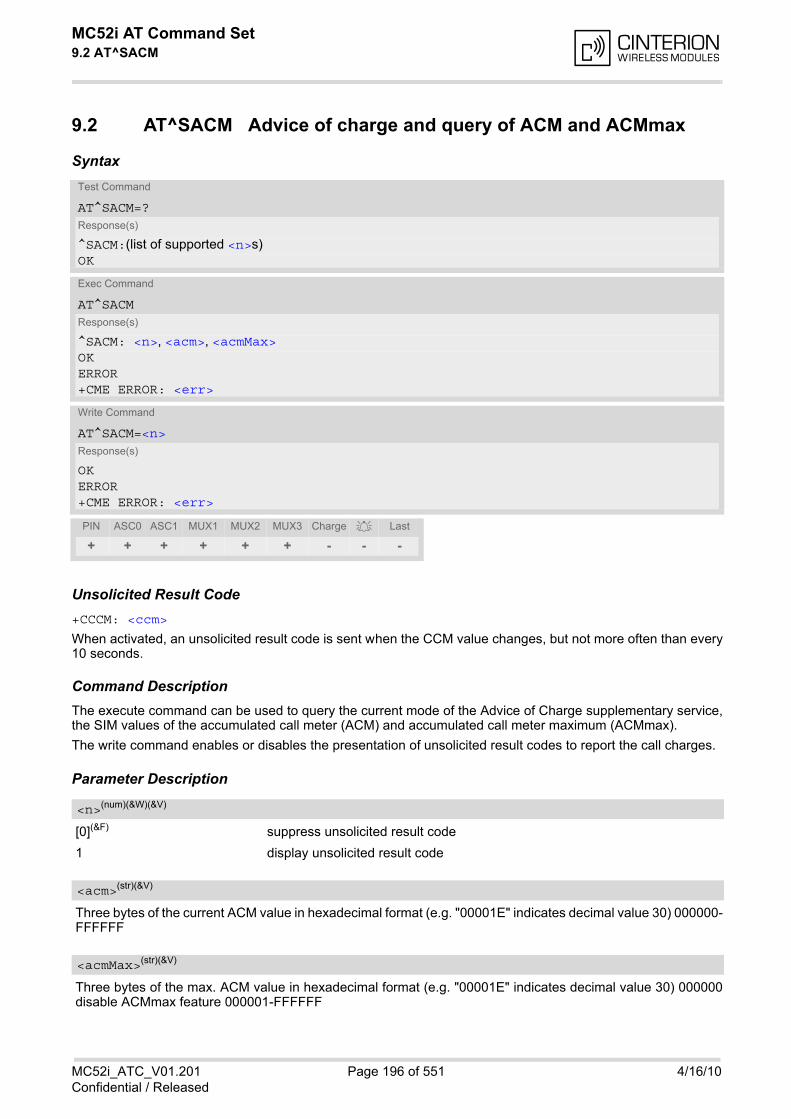
MC52i AT Command Set 9.2 AT^SACM
MC52i_ATC_V01.201 Page 196 of 551 4/16/10Confidential / Released
9.2 AT^SACM Advice of charge and query of ACM and ACMmax
Syntax
Unsolicited Result Code+CCCM: <ccm>
When activated, an unsolicited result code is sent when the CCM value changes, but not more often than every10 seconds.
Command DescriptionThe execute command can be used to query the current mode of the Advice of Charge supplementary service,the SIM values of the accumulated call meter (ACM) and accumulated call meter maximum (ACMmax).
The write command enables or disables the presentation of unsolicited result codes to report the call charges.
Parameter Description
[0](&F) suppress unsolicited result code
1 display unsolicited result code
Three bytes of the current ACM value in hexadecimal format (e.g. "00001E" indicates decimal value 30) 000000-FFFFFF
Three bytes of the max. ACM value in hexadecimal format (e.g. "00001E" indicates decimal value 30) 000000disable ACMmax feature 000001-FFFFFF
Test Command
AT^SACM=?Response(s)
^SACM:(list of supported <n>s)OK
Exec Command
AT^SACMResponse(s)
^SACM: <n>, <acm>, <acmMax>OKERROR+CME ERROR: <err>
Write Command
AT^SACM=<n>Response(s)
OKERROR+CME ERROR: <err>
PIN ASC0 ASC1 MUX1 MUX2 MUX3 Charge Last
+ + + + + + - - -
<n>(num)(&W)(&V)
<acm>(str)(&V)
<acmMax>(str)(&V)
MC52i AT Command Set 9.2 AT^SACM
MC52i_ATC_V01.201 Page 197 of 551 4/16/10Confidential / Released
Three bytes of the current CCM value in hexadecimal format (e.g. "00001E" indicates decimal value 30); bytesare coded in the same way as ACMmax value in the SIM 000000-FFFFFF
Notes• When you power down or reset the ME with AT+CFUN=1,1 the URC presentation mode will be reset to its
default. To benefit from the URC it is recommended to have the setting included in the user profile saved withAT&W, or to select <n>=1 every time you reboot the ME.
• See also GSM07.07: AT+CACM, AT+CAMM, AT+CAOC.
<ccm>(str)

MC52i AT Command Set 9.3 AT+CAMM
MC52i_ATC_V01.201 Page 198 of 551 4/16/10Confidential / Released
9.3 AT+CAMM Accumulated call meter maximum (ACMmax) set or query
Syntax
Command DescriptionThe read command returns the current ACMmax value.
The write command sets the Advice of Charge related to the accumulated call meter maximum value in SIM fileEF (ACMmax). ACMmax contains the maximum number of home units allowed to be consumed by the sub-scriber.
Parameter Description
Three bytes of the max. ACM value in hexadecimal format (e.g. "00001E" indicates decimal value 30) 000000disable ACMmax feature 000001-FFFFFF.
SIM PIN2
Test Command
AT+CAMM=?Response(s)
OK
Read Command
AT+CAMM?Response(s)
+CAMM: <acmmax>OKERROR+CME ERROR: <err>
Write Command
AT+CAMM=<acmmax>[, <passwd>]Response(s)
OKERROR+CME ERROR: <err>
PIN ASC0 ASC1 MUX1 MUX2 MUX3 Charge Last Reference(s)
+ + + + + + - - - GSM 07.07
<acmmax>(str)
<passwd>(str)

MC52i AT Command Set 9.4 AT+CAOC
MC52i_ATC_V01.201 Page 199 of 551 4/16/10Confidential / Released
9.4 AT+CAOC Advice of Charge information
Syntax
Command DescriptionExecute command returns the current call meter value.
The write command sets the Advice of Charge supplementary service function mode.
Parameter Description
0 query CCM value
Three bytes of the current CCM value in hexadecimal format (e.g. "00001E" indicates decimal value 30); bytesare similarly coded as ACMmax value in the SIM 000000-FFFFFF.
Test Command
AT+CAOC=?Response(s)
+CAOC: (list of supported<mode>s)OK
Read Command
AT+CAOC?Response(s)
+CAOC: <mode>OK
Exec Command
AT+CAOCResponse(s)
ERROR+CME ERROR: <err>If <mode>=0, TA returns the current call meter value:+CAOC: <ccm>OK
Write Command
AT+CAOC=[<mode>]Response(s)
ERROR+CME ERROR: <err>If <mode>=0, TA returns the current call meter value.OK
PIN ASC0 ASC1 MUX1 MUX2 MUX3 Charge Last Reference(s)
+ + + + + + - - - GSM 07.07
<mode>(num)(&V)
<ccm>(str)
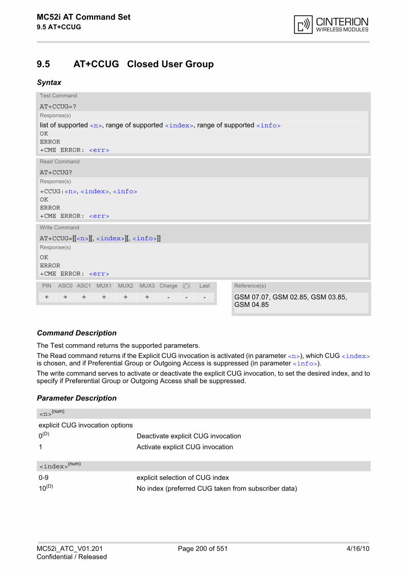
MC52i AT Command Set 9.5 AT+CCUG
MC52i_ATC_V01.201 Page 200 of 551 4/16/10Confidential / Released
9.5 AT+CCUG Closed User Group
Syntax
Command DescriptionThe Test command returns the supported parameters.
The Read command returns if the Explicit CUG invocation is activated (in parameter <n>), which CUG <index>is chosen, and if Preferential Group or Outgoing Access is suppressed (in parameter <info>).
The write command serves to activate or deactivate the explicit CUG invocation, to set the desired index, and tospecify if Preferential Group or Outgoing Access shall be suppressed.
Parameter Description
explicit CUG invocation options
0(D) Deactivate explicit CUG invocation
1 Activate explicit CUG invocation
0-9 explicit selection of CUG index
10(D) No index (preferred CUG taken from subscriber data)
Test Command
AT+CCUG=?Response(s)
list of supported <n>, range of supported <index>, range of supported <info>OKERROR+CME ERROR: <err>
Read Command
AT+CCUG?Response(s)
+CCUG:<n>, <index>, <info>OKERROR+CME ERROR: <err>
Write Command
AT+CCUG=[[<n>][, <index>][, <info>]]Response(s)
OKERROR+CME ERROR: <err>
PIN ASC0 ASC1 MUX1 MUX2 MUX3 Charge Last Reference(s)
+ + + + + + - - - GSM 07.07, GSM 02.85, GSM 03.85, GSM 04.85
<n>(num)
<index>(num)

MC52i AT Command Set 9.5 AT+CCUG
MC52i_ATC_V01.201 Page 201 of 551 4/16/10Confidential / Released
state of the call
0(D) no information
1 suppress outgoing access
2 suppress preferential CUG
3 Suppress preferential CUG and Outgoing Access.
Notes• The active settings for omitted parameters are retained without changes.
• Explicit CUG invocation means that at each call setup, CUG information is added to the called number.
• Upon delivery, settings are predefined with <n>=0, <index>=10, <info>=0. These delivery defaults cannot be recalled automatically.
• When starting a call with ATD, Parameter 'G' or 'g' of command ATD will have no effect if the option selectedfor this single call is identical to the option already selected with AT+CCUG.
• Current settings are saved in the ME automatically.
• ATZ or AT&F do not influence the current settings.
• some combinations of parameters may lead to rejection of CUG calls by the network. For more information,please consult GSM 04.85
<info>(num)

MC52i AT Command Set 9.6 AT+CCFC
MC52i_ATC_V01.201 Page 202 of 551 4/16/10Confidential / Released
9.6 AT+CCFC Call forwarding number and conditions control
AT+CCFC controls the call forwarding supplementary service. Registration, erasure, activation, deactivation andstatus query are supported.
Syntax
Parameter Description
Reason for call forwarding
0 unconditional
1 mobile busy
2 no reply
3 not reachable
4 all call forwarding (includes reasons 0, 1, 2 and 3)
5 all conditional call forwarding (includes reasons 1, 2 and 3)
Network operation to be performed for Supplementary service "call forwarding"
0 disable call forwarding (disable service)
1 enable call forwarding (enable service)
2 query status of call forwarding (query service status)
3 register <number> and activate call forwarding (register service)
4 erase <number> and deactivate call forwarding (erase service)
Test Command
AT+CCFC=?Response(s)
+CCFC:(list/range of supported <reason>s) OK
Write Command
AT+CCFC=<reason>, <mode>[, <number>[, <type>[, <class>[, <time>]]]]Response(s)
If <mode> is not equal 2 and command successful: OKIf <mode>= 2, <reason> is not equal 2 and command successful: +CCFC: <status>, <class>[, <number>, <type>]OKIf <mode>= 2, <reason>= 2 and command successful: +CCFC: <status>, <class>[, <number>, <type>, <time>]OKIf error is related to ME functionality ERROR+CME ERROR: <err>
PIN ASC0 ASC1 MUX1 MUX2 MUX3 Charge Last Reference(s)
+ + + + + + - - - GSM 07.07, GSM 02.04, GSM 02.82, GSM 03.82, GSM 04.82
<reason>(num)
<mode>(num)
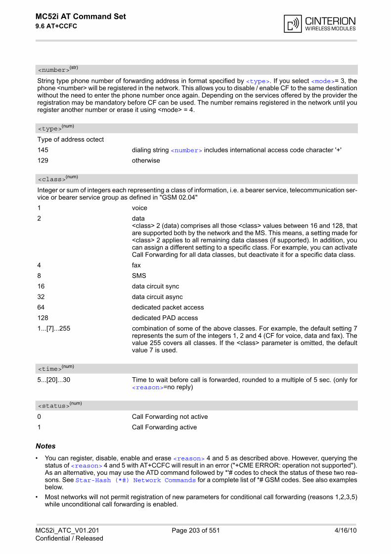
MC52i AT Command Set 9.6 AT+CCFC
MC52i_ATC_V01.201 Page 203 of 551 4/16/10Confidential / Released
String type phone number of forwarding address in format specified by <type>. If you select <mode>= 3, thephone <number> will be registered in the network. This allows you to disable / enable CF to the same destinationwithout the need to enter the phone number once again. Depending on the services offered by the provider theregistration may be mandatory before CF can be used. The number remains registered in the network until youregister another number or erase it using <mode> = 4.
Type of address octect
145 dialing string <number> includes international access code character '+'
129 otherwise
Integer or sum of integers each representing a class of information, i.e. a bearer service, telecommunication ser-vice or bearer service group as defined in "GSM 02.04"
1 voice
2 data<class> 2 (data) comprises all those <class> values between 16 and 128, thatare supported both by the network and the MS. This means, a setting made for<class> 2 applies to all remaining data classes (if supported). In addition, youcan assign a different setting to a specific class. For example, you can activateCall Forwarding for all data classes, but deactivate it for a specific data class.
4 fax
8 SMS
16 data circuit sync
32 data circuit async
64 dedicated packet access
128 dedicated PAD access
1...[7]...255 combination of some of the above classes. For example, the default setting 7represents the sum of the integers 1, 2 and 4 (CF for voice, data and fax). Thevalue 255 covers all classes. If the <class> parameter is omitted, the defaultvalue 7 is used.
5...[20]...30 Time to wait before call is forwarded, rounded to a multiple of 5 sec. (only for<reason>=no reply)
0 Call Forwarding not active
1 Call Forwarding active
Notes• You can register, disable, enable and erase <reason> 4 and 5 as described above. However, querying the
status of <reason> 4 and 5 with AT+CCFC will result in an error ("+CME ERROR: operation not supported").As an alternative, you may use the ATD command followed by *'# codes to check the status of these two rea-sons. See Star-Hash (*#) Network Commands for a complete list of *# GSM codes. See also examplesbelow.
• Most networks will not permit registration of new parameters for conditional call forwarding (reasons 1,2,3,5)while unconditional call forwarding is enabled.
<number>(str)
<type>(num)
<class>(num)
<time>(num)
<status>(num)
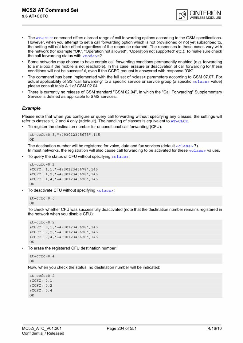
MC52i AT Command Set 9.6 AT+CCFC
MC52i_ATC_V01.201 Page 204 of 551 4/16/10Confidential / Released
• The AT+CCFC command offers a broad range of call forwarding options according to the GSM specifications.However, when you attempt to set a call forwarding option which is not provisioned or not yet subscribed to,the setting will not take effect regardless of the response returned. The responses in these cases vary withthe network (for example "OK", "Operation not allowed", "Operation not supported" etc.). To make sure checkthe call forwarding status with <mode>=2.
• Some networks may choose to have certain call forwarding condtions permanently enabled (e.g. forwardingto a mailbox if the mobile is not reachable). In this case, erasure or deactivation of call forwarding for theseconditions will not be successful, even if the CCFC request is answered with response "OK".
• The command has been implemented with the full set of <class> parameters according to GSM 07.07. Foractual applicability of SS "call forwarding" to a specific service or service group (a specific <class> value)please consult table A.1 of GSM 02.04.
• There is currently no release of GSM standard "GSM 02.04", in which the "Call Forwarding" SupplementaryService is defined as applicable to SMS services.
Example
Please note that when you configure or query call forwarding without specifying any classes, the settings willrefer to classes 1, 2 and 4 only (=default). The handling of classes is equivalent to AT+CLCK.
• To register the destination number for unconditional call forwarding (CFU):
The destination number will be registered for voice, data and fax services (default <class> 7).In most networks, the registration will also cause call forwarding to be activated for these <class> values.
• To query the status of CFU without specifying <class>:
• To deactivate CFU without specifying <class>:
To check whether CFU was successfully deactivated (note that the destination number remains registered inthe network when you disable CFU):
• To erase the registered CFU destination number:
Now, when you check the status, no destination number will be indicated:
at+ccfc=0,3,"+493012345678",145 OK
at+ccfc=0,2 +CCFC: 1,1,"+493012345678",145 +CCFC: 1,2,"+493012345678",145 +CCFC: 1,4,"+493012345678",145 OK
at+ccfc=0,0 OK
at+ccfc=0,2 +CCFC: 0,1,"+493012345678",145 +CCFC: 0,2,"+493012345678",145 +CCFC: 0,4,"+493012345678",145 OK
at+ccfc=0,4 OK
at+ccfc=0,2 +CCFC: 0,1 +CCFC: 0,2 +CCFC: 0,4 OK
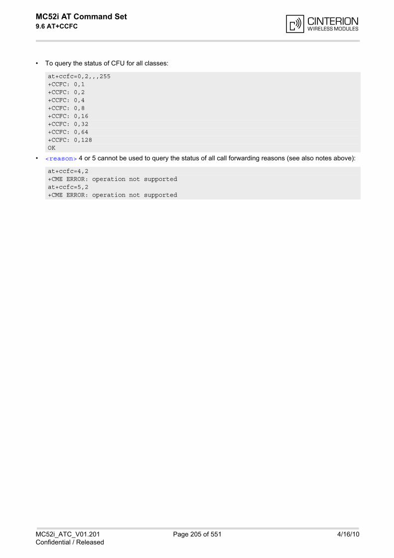
MC52i AT Command Set 9.6 AT+CCFC
MC52i_ATC_V01.201 Page 205 of 551 4/16/10Confidential / Released
• To query the status of CFU for all classes:
• <reason> 4 or 5 cannot be used to query the status of all call forwarding reasons (see also notes above):
at+ccfc=0,2,,,255 +CCFC: 0,1 +CCFC: 0,2 +CCFC: 0,4 +CCFC: 0,8 +CCFC: 0,16 +CCFC: 0,32 +CCFC: 0,64 +CCFC: 0,128 OK
at+ccfc=4,2 +CME ERROR: operation not supported at+ccfc=5,2 +CME ERROR: operation not supported
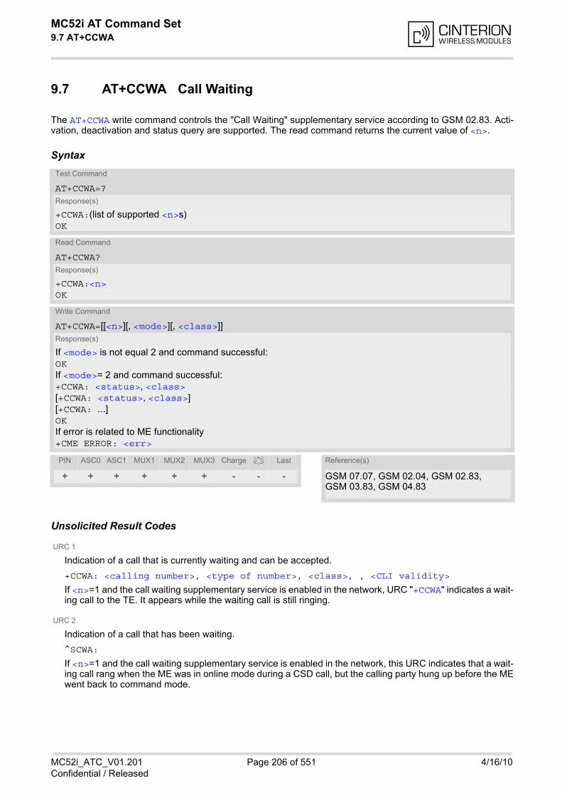
MC52i AT Command Set 9.7 AT+CCWA
MC52i_ATC_V01.201 Page 206 of 551 4/16/10Confidential / Released
9.7 AT+CCWA Call Waiting
The AT+CCWA write command controls the "Call Waiting" supplementary service according to GSM 02.83. Acti-vation, deactivation and status query are supported. The read command returns the current value of <n>.
Syntax
Unsolicited Result Codes
URC 1
Indication of a call that is currently waiting and can be accepted.
+CCWA: <calling number>, <type of number>, <class>, , <CLI validity>
If <n>=1 and the call waiting supplementary service is enabled in the network, URC "+CCWA" indicates a wait-ing call to the TE. It appears while the waiting call is still ringing.
URC 2
Indication of a call that has been waiting.
^SCWA:
If <n>=1 and the call waiting supplementary service is enabled in the network, this URC indicates that a wait-ing call rang when the ME was in online mode during a CSD call, but the calling party hung up before the MEwent back to command mode.
Test Command
AT+CCWA=?Response(s)
+CCWA:(list of supported <n>s) OK
Read Command
AT+CCWA?Response(s)
+CCWA:<n> OK
Write Command
AT+CCWA=[[<n>][, <mode>][, <class>]]Response(s)
If <mode> is not equal 2 and command successful: OKIf <mode>= 2 and command successful: +CCWA: <status>, <class>[+CCWA: <status>, <class>][+CCWA: ...]OKIf error is related to ME functionality +CME ERROR: <err>
PIN ASC0 ASC1 MUX1 MUX2 MUX3 Charge Last Reference(s)
+ + + + + + - - - GSM 07.07, GSM 02.04, GSM 02.83, GSM 03.83, GSM 04.83
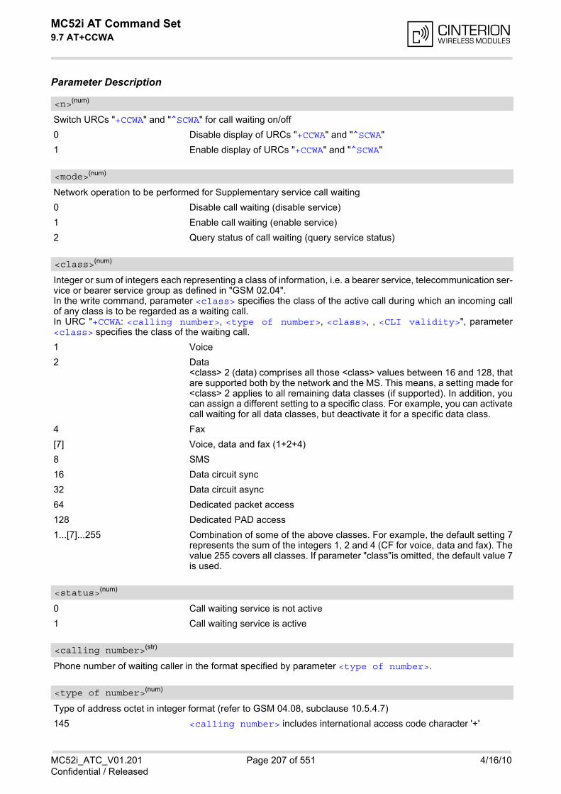
MC52i AT Command Set 9.7 AT+CCWA
MC52i_ATC_V01.201 Page 207 of 551 4/16/10Confidential / Released
Parameter Description
Switch URCs "+CCWA" and "^SCWA" for call waiting on/off
0 Disable display of URCs "+CCWA" and "^SCWA"
1 Enable display of URCs "+CCWA" and "^SCWA"
Network operation to be performed for Supplementary service call waiting
0 Disable call waiting (disable service)
1 Enable call waiting (enable service)
2 Query status of call waiting (query service status)
Integer or sum of integers each representing a class of information, i.e. a bearer service, telecommunication ser-vice or bearer service group as defined in "GSM 02.04".In the write command, parameter <class> specifies the class of the active call during which an incoming callof any class is to be regarded as a waiting call.In URC "+CCWA: <calling number>, <type of number>, <class>, , <CLI validity>", parameter<class> specifies the class of the waiting call.
1 Voice
2 Data<class> 2 (data) comprises all those <class> values between 16 and 128, thatare supported both by the network and the MS. This means, a setting made for<class> 2 applies to all remaining data classes (if supported). In addition, youcan assign a different setting to a specific class. For example, you can activatecall waiting for all data classes, but deactivate it for a specific data class.
4 Fax
[7] Voice, data and fax (1+2+4)
8 SMS
16 Data circuit sync
32 Data circuit async
64 Dedicated packet access
128 Dedicated PAD access
1...[7]...255 Combination of some of the above classes. For example, the default setting 7represents the sum of the integers 1, 2 and 4 (CF for voice, data and fax). Thevalue 255 covers all classes. If parameter "class"is omitted, the default value 7is used.
0 Call waiting service is not active
1 Call waiting service is active
Phone number of waiting caller in the format specified by parameter <type of number>.
Type of address octet in integer format (refer to GSM 04.08, subclause 10.5.4.7)
145 <calling number> includes international access code character '+'
<n>(num)
<mode>(num)
<class>(num)
<status>(num)
<calling number>(str)
<type of number>(num)

MC52i AT Command Set 9.7 AT+CCWA
MC52i_ATC_V01.201 Page 208 of 551 4/16/10Confidential / Released
128 number restricted
129 Otherwise
0 CLI valid
1 CLI has been withheld
2 CLI is not available
Notes• If the active call is a CSD call, and a waiting call is received, then the ME produces a BREAK while still in
online mode, and displays
- the +CCWA URC (as above) when the ME goes back to command mode while the waiting call is still activeand can be accepted;
- or the ^SCWA URC (as above) when the ME goes back to command mode after the waiting call hasended.
• With the AT+CHLD command, it is possible to establish a multiparty call or to set the active voice call on holdand then accept a waiting voice call (not possible with fax and data call). See also AT+CHLD
• Users should be aware that if call waiting is activated (<mode>=1), the presentation of URCs needs to beenabled, too (<n>=1). Otherwise, on the one hand, a waiting caller would be kept waiting due to lack of BUSY signals, while, on theother hand, the waiting call would not be indicated to the called party.
• The AT+CCWA command offers a broad range of options according to the GSM specifications. However,when you attempt to enable call waiting for a <class> for which the service is not provisioned or not sup-ported , the setting will not take effect regardless of the response returned. The responses in these cases varywith the network (for example "OK", "Operation not allowed", "Operation not supported" etc.). To make surecheck the current call waiting settings with <mode>=2.
• The AT+CCWA command has been implemented with the full set of <class> parameters according toGSM 07.07. For actual applicability of SS call waiting to a specific service or service group (a specific<class> value) please consult table A.1 of GSM 02.04
• Despite the specifications stated in GSM 02.04 call waiting is not handled uniformly among all networks: GSM 02.04, Annex A, provides the following specification: "The applicability of call waiting refers to the telecommunication service of the active call and not of the waitingcall. The incoming, waiting, call may be of any kind." Nevertheless, networks do differ on the actual imple-mentation of the service. For example, the activation of call waiting for <class> 4, "fax", causes some net-works to send a call waiting indication if a call "of any kind" comes in during an active fax call, but others may(with the same settings active) indicate a waiting fax call during any kind of active call. Thus, the only reliableway to receive or prevent a call waiting indication under any circumstances and in any network, is to activateor deactivate call waiting for all tele- and bearer services (<class> 255).
<CLI validity>(num)
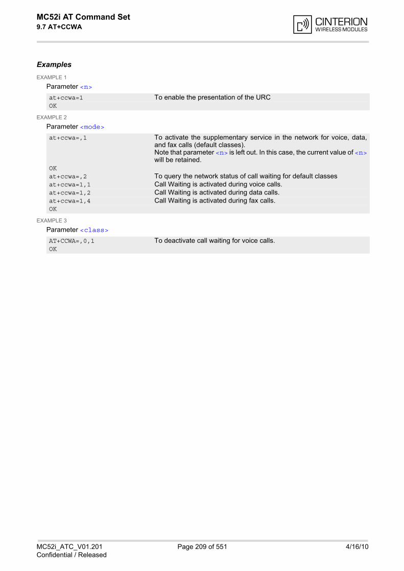
MC52i AT Command Set 9.7 AT+CCWA
MC52i_ATC_V01.201 Page 209 of 551 4/16/10Confidential / Released
ExamplesEXAMPLE 1
Parameter <n>
EXAMPLE 2
Parameter <mode>
EXAMPLE 3
Parameter <class>
at+ccwa=1 To enable the presentation of the URC OK
at+ccwa=,1 To activate the supplementary service in the network for voice, data,and fax calls (default classes). Note that parameter <n> is left out. In this case, the current value of <n>will be retained.
OK at+ccwa=,2 To query the network status of call waiting for default classes at+ccwa=1,1 Call Waiting is activated during voice calls. at+ccwa=1,2 Call Waiting is activated during data calls. at+ccwa=1,4 Call Waiting is activated during fax calls. OK
AT+CCWA=,0,1 To deactivate call waiting for voice calls. OK
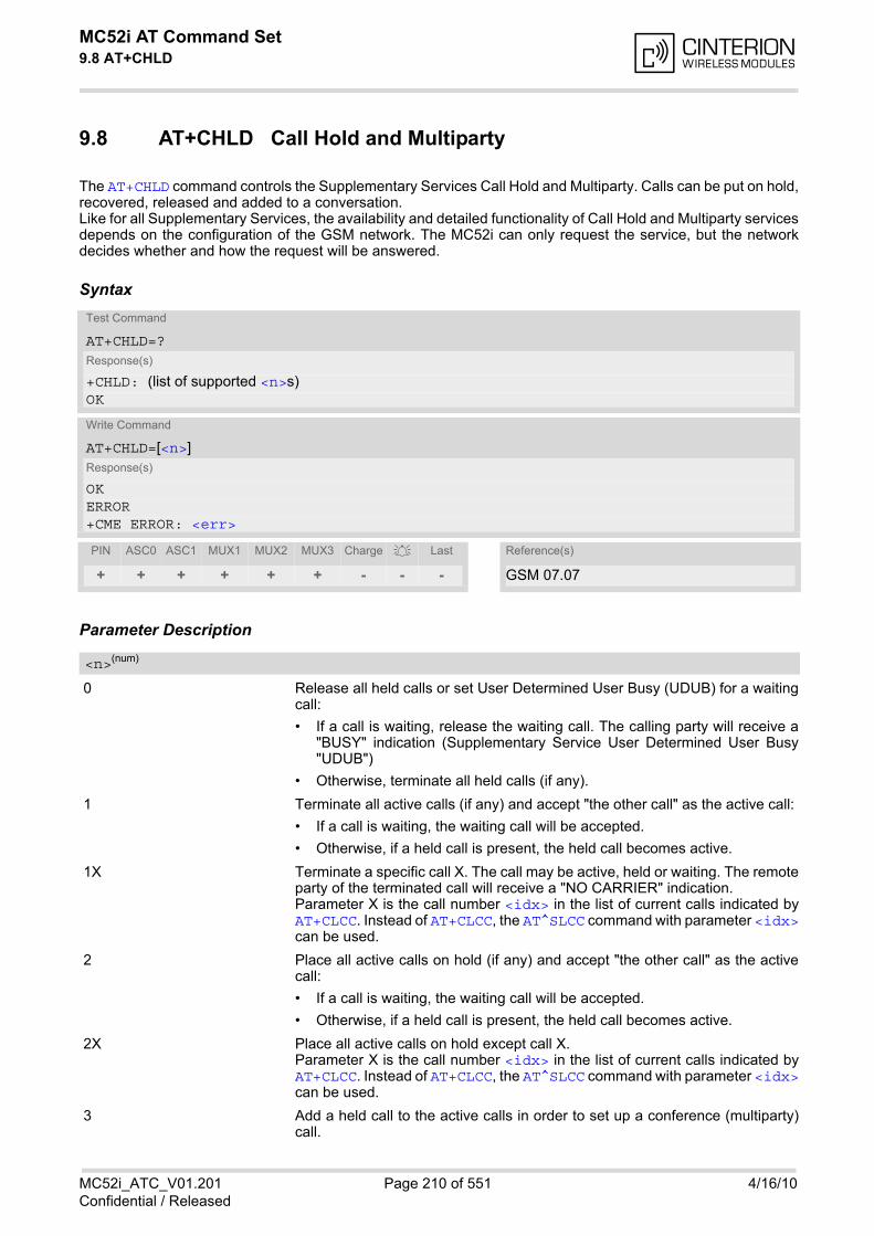
MC52i AT Command Set 9.8 AT+CHLD
MC52i_ATC_V01.201 Page 210 of 551 4/16/10Confidential / Released
9.8 AT+CHLD Call Hold and Multiparty
The AT+CHLD command controls the Supplementary Services Call Hold and Multiparty. Calls can be put on hold,recovered, released and added to a conversation.Like for all Supplementary Services, the availability and detailed functionality of Call Hold and Multiparty servicesdepends on the configuration of the GSM network. The MC52i can only request the service, but the networkdecides whether and how the request will be answered.
Syntax
Parameter Description
0 Release all held calls or set User Determined User Busy (UDUB) for a waitingcall:
• If a call is waiting, release the waiting call. The calling party will receive a"BUSY" indication (Supplementary Service User Determined User Busy"UDUB")
• Otherwise, terminate all held calls (if any).
1 Terminate all active calls (if any) and accept "the other call" as the active call:
• If a call is waiting, the waiting call will be accepted.
• Otherwise, if a held call is present, the held call becomes active.
1X Terminate a specific call X. The call may be active, held or waiting. The remoteparty of the terminated call will receive a "NO CARRIER" indication. Parameter X is the call number <idx> in the list of current calls indicated byAT+CLCC. Instead of AT+CLCC, the AT^SLCC command with parameter <idx>can be used.
2 Place all active calls on hold (if any) and accept "the other call" as the activecall:
• If a call is waiting, the waiting call will be accepted.
• Otherwise, if a held call is present, the held call becomes active.
2X Place all active calls on hold except call X.Parameter X is the call number <idx> in the list of current calls indicated byAT+CLCC. Instead of AT+CLCC, the AT^SLCC command with parameter <idx>can be used.
3 Add a held call to the active calls in order to set up a conference (multiparty)call.
Test Command
AT+CHLD=?Response(s)
+CHLD: (list of supported <n>s)OK
Write Command
AT+CHLD=[<n>]Response(s)
OKERROR+CME ERROR: <err>
PIN ASC0 ASC1 MUX1 MUX2 MUX3 Charge Last Reference(s)
+ + + + + + - - - GSM 07.07
<n>(num)

MC52i AT Command Set 9.8 AT+CHLD
MC52i_ATC_V01.201 Page 211 of 551 4/16/10Confidential / Released
Notes• The AT+CHLD command offers a broad range of options according to the GSM specifications. However, if you
attempt to invoke an option which is not provisioned by the network, or not subscribed to, invocation of thisoption will fail. The responses in these cases may vary with the network (for example "Operation not allowed","Operation not supported" etc.).
• The handling of the supplementary service Call hold and Multiparty varies with the types of calls. This isbecause only voice calls can be put on hold, while data or fax calls cannot. The following procedures apply:With AT+CHLD=2 the user can simultaneously place a voice call on hold and accept another waiting voice,data or fax call. If the waiting call is a data or fax call, it is also possible to put the voice call on hold. To switchback from the active data or fax call to the held voice call the active call must be terminated with AT+CHLD=1.If all active and held calls are voice calls it is possible to switch back and forth with AT+CHLD=2.
• In conflict situations, e.g. when a waiting call comes while there are already held calls, the above proceduresapply to the waiting call only. For example, <n>=0 rejects the waiting call, but does not affect the held calls.
• See also the AT+CCWA command for details on how to display waiting calls.
Example
^SYSSTARTat+cpin="9999"OK+CREG: 2+CREG: 1,"0145","0016" The mobile is now registered.at+ccwa=1,1,1 You activate the indication of waiting calls during
voice calls.OKatd"1234567"; You make a voice call.OK+CCWA: "+491791292364",145,32,,0 You receive a URC indicating a waiting data call.at+chld=2 You put the voice call on hold.CONNECT 9600/RLP The data connection is set up.hello+++ With ''+++'' you go in command mode.OKat+clcc You interrogate the status of all established calls.+CLCC: 1,0,1,0,0,"03038639268",129+CLCC: 2,1,0,1,0,"+491791292364",145OKat+chld=1 The active data call is terminated and the held voice
call becomes active.OKat+clcc+CLCC: 1,0,0,0,0,"03038639268",129OK
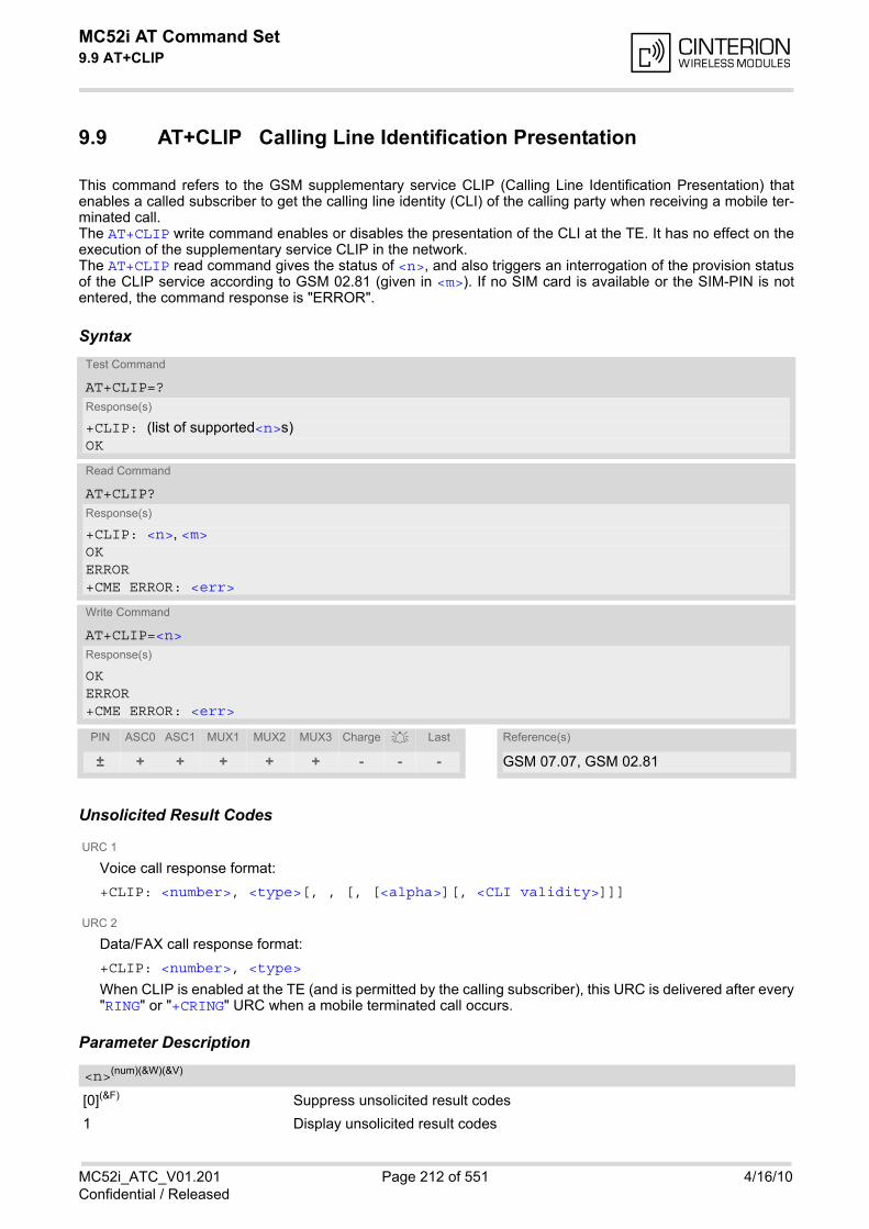
MC52i AT Command Set 9.9 AT+CLIP
MC52i_ATC_V01.201 Page 212 of 551 4/16/10Confidential / Released
9.9 AT+CLIP Calling Line Identification Presentation
This command refers to the GSM supplementary service CLIP (Calling Line Identification Presentation) thatenables a called subscriber to get the calling line identity (CLI) of the calling party when receiving a mobile ter-minated call. The AT+CLIP write command enables or disables the presentation of the CLI at the TE. It has no effect on theexecution of the supplementary service CLIP in the network. The AT+CLIP read command gives the status of <n>, and also triggers an interrogation of the provision statusof the CLIP service according to GSM 02.81 (given in <m>). If no SIM card is available or the SIM-PIN is notentered, the command response is "ERROR".
Syntax
Unsolicited Result Codes
URC 1
Voice call response format:
+CLIP: <number>, <type>[, , [, [<alpha>][, <CLI validity>]]]
URC 2
Data/FAX call response format:
+CLIP: <number>, <type>
When CLIP is enabled at the TE (and is permitted by the calling subscriber), this URC is delivered after every"RING" or "+CRING" URC when a mobile terminated call occurs.
Parameter Description
[0](&F) Suppress unsolicited result codes
1 Display unsolicited result codes
Test Command
AT+CLIP=?Response(s)
+CLIP: (list of supported<n>s)OK
Read Command
AT+CLIP?Response(s)
+CLIP: <n>, <m>OKERROR+CME ERROR: <err>
Write Command
AT+CLIP=<n>Response(s)
OKERROR+CME ERROR: <err>
PIN ASC0 ASC1 MUX1 MUX2 MUX3 Charge Last Reference(s)
± + + + + + - - - GSM 07.07, GSM 02.81
<n>(num)(&W)(&V)
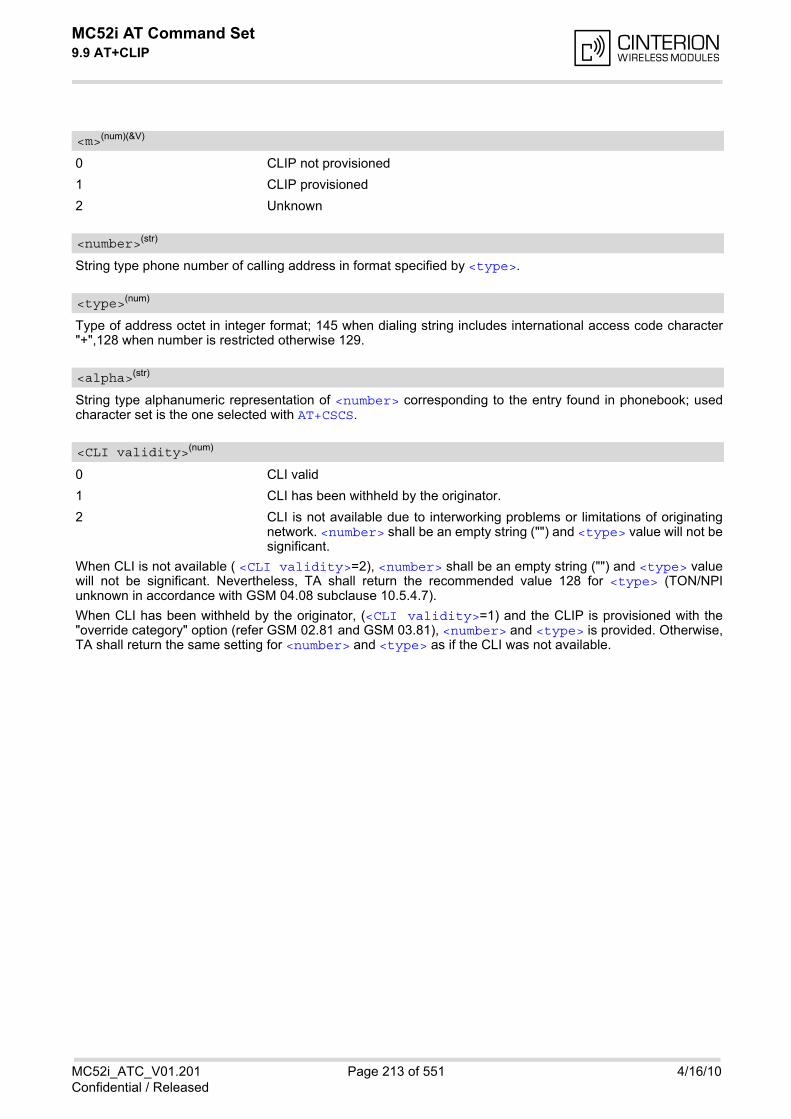
MC52i AT Command Set 9.9 AT+CLIP
MC52i_ATC_V01.201 Page 213 of 551 4/16/10Confidential / Released
0 CLIP not provisioned
1 CLIP provisioned
2 Unknown
String type phone number of calling address in format specified by <type>.
Type of address octet in integer format; 145 when dialing string includes international access code character"+",128 when number is restricted otherwise 129.
String type alphanumeric representation of <number> corresponding to the entry found in phonebook; usedcharacter set is the one selected with AT+CSCS.
0 CLI valid
1 CLI has been withheld by the originator.
2 CLI is not available due to interworking problems or limitations of originatingnetwork. <number> shall be an empty string ("") and <type> value will not besignificant.
When CLI is not available ( <CLI validity>=2), <number> shall be an empty string ("") and <type> valuewill not be significant. Nevertheless, TA shall return the recommended value 128 for <type> (TON/NPIunknown in accordance with GSM 04.08 subclause 10.5.4.7).
When CLI has been withheld by the originator, (<CLI validity>=1) and the CLIP is provisioned with the"override category" option (refer GSM 02.81 and GSM 03.81), <number> and <type> is provided. Otherwise,TA shall return the same setting for <number> and <type> as if the CLI was not available.
<m>(num)(&V)
<number>(str)
<type>(num)
<alpha>(str)
<CLI validity>(num)
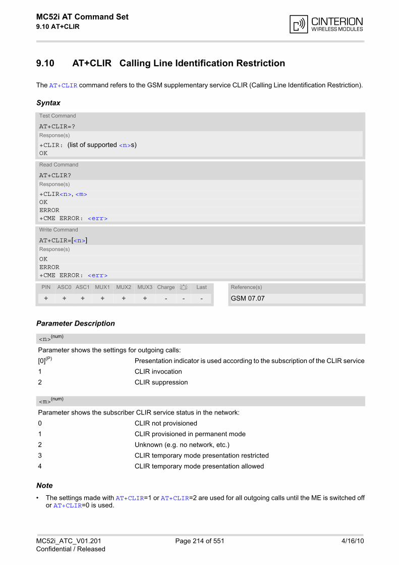
MC52i AT Command Set 9.10 AT+CLIR
MC52i_ATC_V01.201 Page 214 of 551 4/16/10Confidential / Released
9.10 AT+CLIR Calling Line Identification Restriction
The AT+CLIR command refers to the GSM supplementary service CLIR (Calling Line Identification Restriction).
Syntax
Parameter Description
Parameter shows the settings for outgoing calls:
[0](P) Presentation indicator is used according to the subscription of the CLIR service
1 CLIR invocation
2 CLIR suppression
Parameter shows the subscriber CLIR service status in the network:
0 CLIR not provisioned
1 CLIR provisioned in permanent mode
2 Unknown (e.g. no network, etc.)
3 CLIR temporary mode presentation restricted
4 CLIR temporary mode presentation allowed
Note• The settings made with AT+CLIR=1 or AT+CLIR=2 are used for all outgoing calls until the ME is switched off
or AT+CLIR=0 is used.
Test Command
AT+CLIR=?Response(s)
+CLIR: (list of supported <n>s)OK
Read Command
AT+CLIR?Response(s)
+CLIR<n>, <m>OKERROR+CME ERROR: <err>
Write Command
AT+CLIR=[<n>]Response(s)
OKERROR+CME ERROR: <err>
PIN ASC0 ASC1 MUX1 MUX2 MUX3 Charge Last Reference(s)
+ + + + + + - - - GSM 07.07
<n>(num)
<m>(num)
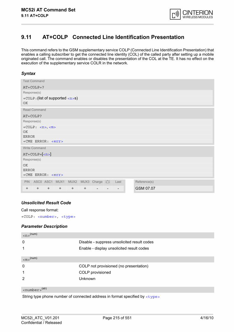
MC52i AT Command Set 9.11 AT+COLP
MC52i_ATC_V01.201 Page 215 of 551 4/16/10Confidential / Released
9.11 AT+COLP Connected Line Identification Presentation
This command refers to the GSM supplementary service COLP (Connected Line Identification Presentation) thatenables a calling subscriber to get the connected line identity (COL) of the called party after setting up a mobileoriginated call. The command enables or disables the presentation of the COL at the TE. It has no effect on theexecution of the supplementary service COLR in the network.
Syntax
Unsolicited Result CodeCall response format:
+COLP: <number>, <type>
Parameter Description
0 Disable - suppress unsolicited result codes
1 Enable - display unsolicited result codes
0 COLP not provisioned (no presentation)
1 COLP provisioned
2 Unknown
String type phone number of connected address in format specified by <type>
Test Command
AT+COLP=?Response(s)
+COLP:(list of supported <n>s)OK
Read Command
AT+COLP?Response(s)
+COLP: <n>, <m>OKERROR+CME ERROR: <err>
Write Command
AT+COLP=[<n>]Response(s)
OKERROR+CME ERROR: <err>
PIN ASC0 ASC1 MUX1 MUX2 MUX3 Charge Last Reference(s)
+ + + + + + - - - GSM 07.07
<n>(num)
<m>(num)
<number>(str)

MC52i AT Command Set 9.11 AT+COLP
MC52i_ATC_V01.201 Page 216 of 551 4/16/10Confidential / Released
Type of address octet in integer format; 145 when dialling string includes international access code character"+", otherwise 129.
<type>(num)
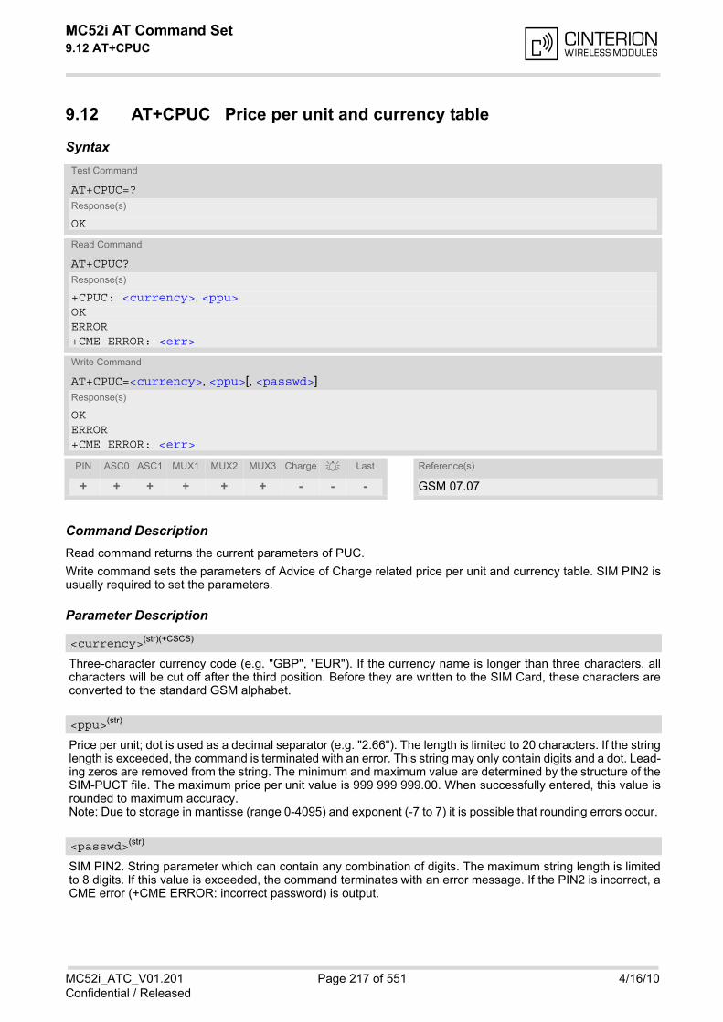
MC52i AT Command Set 9.12 AT+CPUC
MC52i_ATC_V01.201 Page 217 of 551 4/16/10Confidential / Released
9.12 AT+CPUC Price per unit and currency table
Syntax
Command DescriptionRead command returns the current parameters of PUC.
Write command sets the parameters of Advice of Charge related price per unit and currency table. SIM PIN2 isusually required to set the parameters.
Parameter Description
Three-character currency code (e.g. "GBP", "EUR"). If the currency name is longer than three characters, allcharacters will be cut off after the third position. Before they are written to the SIM Card, these characters areconverted to the standard GSM alphabet.
Price per unit; dot is used as a decimal separator (e.g. "2.66"). The length is limited to 20 characters. If the stringlength is exceeded, the command is terminated with an error. This string may only contain digits and a dot. Lead-ing zeros are removed from the string. The minimum and maximum value are determined by the structure of theSIM-PUCT file. The maximum price per unit value is 999 999 999.00. When successfully entered, this value isrounded to maximum accuracy.Note: Due to storage in mantisse (range 0-4095) and exponent (-7 to 7) it is possible that rounding errors occur.
SIM PIN2. String parameter which can contain any combination of digits. The maximum string length is limitedto 8 digits. If this value is exceeded, the command terminates with an error message. If the PIN2 is incorrect, aCME error (+CME ERROR: incorrect password) is output.
Test Command
AT+CPUC=?Response(s)
OK
Read Command
AT+CPUC?Response(s)
+CPUC: <currency>, <ppu>OKERROR+CME ERROR: <err>
Write Command
AT+CPUC=<currency>, <ppu>[, <passwd>]Response(s)
OKERROR+CME ERROR: <err>
PIN ASC0 ASC1 MUX1 MUX2 MUX3 Charge Last Reference(s)
+ + + + + + - - - GSM 07.07
<currency>(str)(+CSCS)
<ppu>(str)
<passwd>(str)
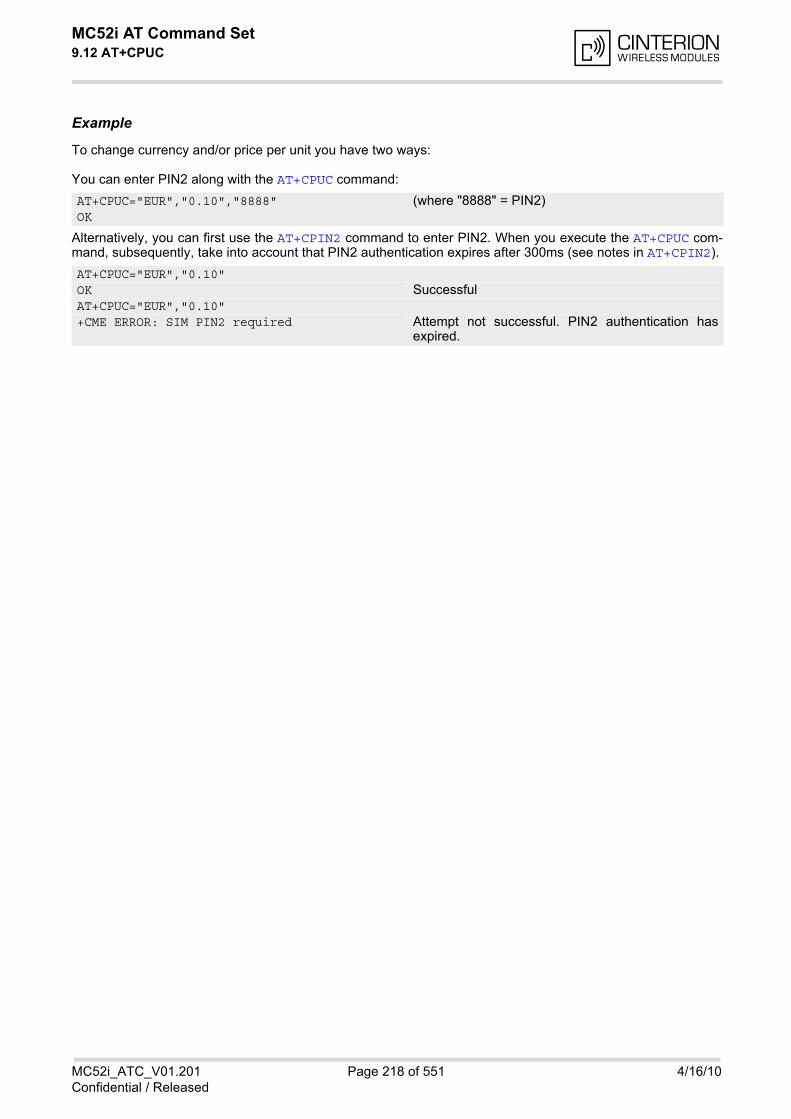
MC52i AT Command Set 9.12 AT+CPUC
MC52i_ATC_V01.201 Page 218 of 551 4/16/10Confidential / Released
Example
To change currency and/or price per unit you have two ways:
You can enter PIN2 along with the AT+CPUC command:
Alternatively, you can first use the AT+CPIN2 command to enter PIN2. When you execute the AT+CPUC com-mand, subsequently, take into account that PIN2 authentication expires after 300ms (see notes in AT+CPIN2).
AT+CPUC="EUR","0.10","8888" (where "8888" = PIN2)OK
AT+CPUC="EUR","0.10"OK SuccessfulAT+CPUC="EUR","0.10"+CME ERROR: SIM PIN2 required Attempt not successful. PIN2 authentication has
expired.

MC52i AT Command Set 9.13 AT+CSSN
MC52i_ATC_V01.201 Page 219 of 551 4/16/10Confidential / Released
9.13 AT+CSSN Supplementary service notifications
Syntax
Unsolicited Result Codes
URC 1
+CSSI: <code 1>
When <n>=1 and a supplementary service notification is received after a mobile originated call setup, inter-mediate result code "+CSSI: <code 1>" is sent to TE before any other MO call setup result codes
URC 2
+CSSU: <code 2>
When <m>=1 and a supplementary service notification is received during a mobile terminated call setup orduring a call, unsolicited result code "+CSSU: <code 2>" is sent to TE.
Command DescriptionThe write command enables or disables the presentation of URCs for supplementary services.
Parameter Description
0(&F)(P) Suppress "+CSSI" URCs
1 Activate "+CSSI" URCs
0(&F)(P) Suppress "+CSSU" URCs
1 Activate "+CSSU" URCs
Test Command
AT+CSSN=?Response(s)
+CSSN: (list of supported<n>s), (list of supported<m>s)OK
Read Command
AT+CSSN?Response(s)
+CSSN: <n>, <m>OK
Write Command
AT+CSSN=<n>[, <m>]Response(s)
OKERROR+CME ERROR: <err>
PIN ASC0 ASC1 MUX1 MUX2 MUX3 Charge Last Reference(s)
- + + + + + - - - GSM 07.07
<n>(num)
<m>(num)
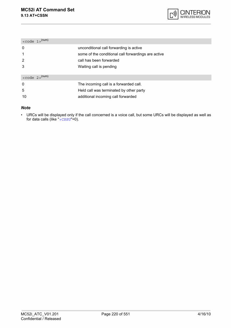
MC52i AT Command Set 9.13 AT+CSSN
MC52i_ATC_V01.201 Page 220 of 551 4/16/10Confidential / Released
0 unconditional call forwarding is active
1 some of the conditional call forwardings are active
2 call has been forwarded
3 Waiting call is pending
0 The incoming call is a forwarded call.
5 Held call was terminated by other party
10 additional incoming call forwarded
Note• URCs will be displayed only if the call concerned is a voice call, but some URCs will be displayed as well as
for data calls (like "+CSSU"=0).
<code 1>(num)
<code 2>(num)
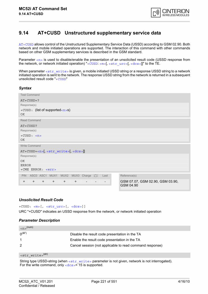
MC52i AT Command Set 9.14 AT+CUSD
MC52i_ATC_V01.201 Page 221 of 551 4/16/10Confidential / Released
9.14 AT+CUSD Unstructured supplementary service data
AT+CUSD allows control of the Unstructured Supplementary Service Data (USSD) according to GSM 02.90. Bothnetwork and mobile initiated operations are supported. The interaction of this command with other commandsbased on other GSM supplementary services is described in the GSM standard.
Parameter <n> is used to disable/enable the presentation of an unsolicited result code (USSD response fromthe network, or network initiated operation) "+CUSD: <m>[, <str_urc>[, <dcs>]]" to the TE.
When parameter <str_write> is given, a mobile initiated USSD string or a response USSD string to a networkinitiated operation is sent to the network. The response USSD string from the network is returned in a subsequentunsolicited result code "+CUSD"
Syntax
Unsolicited Result Code+CUSD: <m>[, <str_urc>[, <dcs>]]
URC "+CUSD" indicates an USSD response from the network, or network initiated operation
Parameter Description
0(&F) Disable the result code presentation in the TA
1 Enable the result code presentation in the TA
2 Cancel session (not applicable to read command response)
String type USSD-string (when <str_write> parameter is not given, network is not interrogated). For the write command, only <dcs>= 15 is supported.
Test Command
AT+CUSD=?Response(s)
+CUSD: (list of supported<n>s)OK
Read Command
AT+CUSD?Response(s)
+CUSD: <n>OK
Write Command
AT+CUSD=<n>[, <str_write>[, <dcs>]]Response(s)
OKERROR+CME ERROR: <err>
PIN ASC0 ASC1 MUX1 MUX2 MUX3 Charge Last Reference(s)
+ + + + + + - - - GSM 07.07, GSM 02.90, GSM 03.90, GSM 04.90
<n>(num)
<str_write>(str)
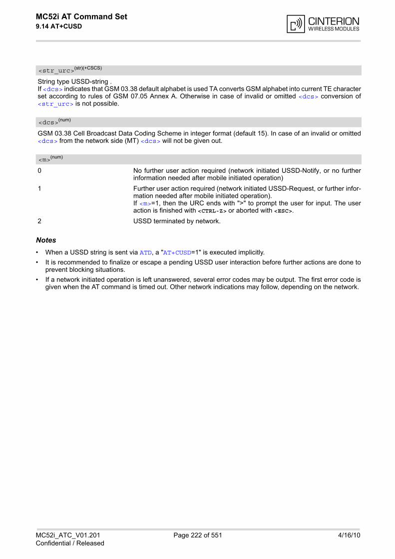
MC52i AT Command Set 9.14 AT+CUSD
MC52i_ATC_V01.201 Page 222 of 551 4/16/10Confidential / Released
String type USSD-string . If <dcs> indicates that GSM 03.38 default alphabet is used TA converts GSM alphabet into current TE characterset according to rules of GSM 07.05 Annex A. Otherwise in case of invalid or omitted <dcs> conversion of<str_urc> is not possible.
GSM 03.38 Cell Broadcast Data Coding Scheme in integer format (default 15). In case of an invalid or omitted<dcs> from the network side (MT) <dcs> will not be given out.
0 No further user action required (network initiated USSD-Notify, or no furtherinformation needed after mobile initiated operation)
1 Further user action required (network initiated USSD-Request, or further infor-mation needed after mobile initiated operation). If <m>=1, then the URC ends with ">" to prompt the user for input. The useraction is finished with <CTRL-Z> or aborted with <ESC>.
2 USSD terminated by network.
Notes• When a USSD string is sent via ATD, a "AT+CUSD=1" is executed implicitly.
• It is recommended to finalize or escape a pending USSD user interaction before further actions are done toprevent blocking situations.
• If a network initiated operation is left unanswered, several error codes may be output. The first error code isgiven when the AT command is timed out. Other network indications may follow, depending on the network.
<str_urc>(str)(+CSCS)
<dcs>(num)
<m>(num)
MC52i AT Command Set 10. Internet Service Commands
MC52i_ATC_V01.201 Page 223 of 551 4/16/10Confidential / Released
10. Internet Service Commands
MC52i has an embedded TCP/IP stack that is driven by AT commands and enables the host application to easilyaccess the Internet. The advantage of this solution is that it eliminates the need for the application manufacturerto implement own TCP/IP and PPP stacks, thus minimizing cost and time to integrate Internet connectivity intoa new or existing host application. This chapter is a reference guide to all the AT commands and responsesdefined for use with the TCP/IP stack.
Access is provided to the following Internet Services:
1. Socket Client and Server for TCP, Client for UDP
2. Transparent TCP Client
3. FTP Client
4. HTTP Client
5. SMTP Client
6. POP3 Client
Two design strategies for using Internet Service AT commands - URC mode or polling mode: The MC52i offers two modes of controlling an Internet session opened with AT^SISO. To select the mode thatbest suits the preferences of your application design use the AT^SCFG command, parameter "Tcp/WithURCs"(refer to <tcpWithUrc>).
• URC mode (delivery default):The progress of an Internet session is URC driven. The URCs notify the host whether data can be sent orreceived, whether data transfer has completed, whether the service can be closed or whether an error hasoccurred. This mechanism eliminates the need to poll the service until the necessary progress information isreceived.To enable the URC mode select: AT^SCFG="Tcp/WithURCs",on.
• Polling mode:In polling mode, the presentation of URCs related to the Internet Services is disabled. The host is responsibleto retrieve all the status information needed for controlling the Internet session. This is done by polling, wherethe host application keeps sending the commands AT^SISR, AT^SISW, AT^SISI. To enable the polling mode select: AT^SCFG="Tcp/WithURCs",off.The disabled URCs are the following: "^SISR" URC, "^SISW" URC and "^SIS" URC for parameter <urc-Cause>=0 (Internet service events), but not for <urcCause>=1 or 2 (needed for Socket listener and alwaysenabled).
Step-by-step overview of how to configure and use TCP/IP communications with MC52i:
• Select URC mode or polling mode as described above.
• First of all, create a CSD or GPRS connection profile with AT^SICS. The connection profile is a set of basicparameters which determines the type of connection to use for an Internet service. The connection type isalso referred to as bearer. Up to 6 connection profiles can be defined, each identified by the <conPro-fileId>.
• Secondly, use AT^SISS to create a service profile based on one of the connection profiles. Up to 10 serviceprofiles can be defined, each identified by the <srvProfileId>. The service profile specifies the type ofInternet service to use, i.e. Socket, FTP, HTTP, or one of the email services SMTP or POP3. To assign aconnection profile to a service profile, the <conProfileId> of AT^SICS must be entered as "conId" valueof the AT^SISS parameter <srvParmTag>. This offers great flexibility to combine connection profiles and service profiles. For example, you may haveone connection profile (CSD or GPRS) specified with AT^SICS which can be associated with an SMTP ser-vice profile for sending emails and a POP3 service profile for retrieving emails.
• Once the connection profile and the service profile are created, an Internet session can be opened by enteringthe AT^SISO write command and the desired <srvProfileId>. In URC mode, the "^SISR" or "^SISW" URC indicates whether the service is ready to receive or send data.This means, that the AT^SISR or AT^SISW command shall be entered after the URC was received. If an error
MC52i AT Command Set
MC52i_ATC_V01.201 Page 224 of 551 4/16/10Confidential / Released
occurs the "^SIS" URC is delivered instead. In polling mode, you can enter the AT^SISR or AT^SISW command straight after AT^SISO though you mayneed to do so several times until the service confirms that data can be sent or received.
• The first parameter of the AT^SISR or AT^SISW commands is always the <srvProfileId>, the secondparameter is the number of bytes which the host either wants to send to or is able to receive from the module.The way the module handles the data transfer follows the rules of the ordinary socket interface and is awarethat a host may be limited by its input buffer size. The maximum data size supported by MC52i is 1500 bytesin both directions (read or write). To send or receive more than 1500 bytes, the read or write action shall berepeated until the data transfer has completed. Each read or write action requires that the command response(of AT^SISR or AT^SISW) confirms that the service is ready to send or receive data. To end an upload data stream set the <eodFlag> in the last AT^SISW command.
• For Transparent TCP service the AT command AT^SIST provides a specific mode for data exchange andaccepts <srvProfileId> only. In that mode the service is connected to the interface in a transparent man-ner and exchanging data is not related to the AT^SISW and AT^SISR cycles. To resume AT command modeenter the +++ escape sequence or toggle the DTR line.
• The AT^SISI command shall be used to monitor the progress of the session. The command reports the ser-vice state of the used service profile and indicates the number of bytes received, the number of bytes sentand, in the case of sending, the number of bytes acknowledged or unacknowledged at TCP layer.
• If an error occurs during a session you can enter the AT^SISE command and the <srvProfileId> to iden-tify the reason. This is especially important in polling mode.
• The AT^SICI command can be used any time to query the current status of one or all connection profile(s).
• Finally, to end a session, enter the AT^SISC write command and the <srvProfileId>.
Maximum number of profiles defined / used:
• Up to 6 connection profiles can be created (with AT^SICS).
• Up to 10 service profiles can be created (with AT^SISS), but the number of parallel profiles of the same ser-vice type is limited as listed below. If the maximum number of a service profile type is already defined, anyattempt to set up another profile for the same type will be denied with "+CME ERROR: operation of servicetemporary not allowed".
- Maximum 3 HTTP profiles
- Maximum 6 socket profiles: The socket service can accept an incoming connection only when at least oneservice profile is still free (not yet created with AT^SISS), otherwise the incoming connection will berejected from the listener.
- 2 Transparent TCP profiles
- 1 FTP profile
- 1 POP3 profile
- 1 SMTP profile
• The TCP/IP stack of MC52i supports one service profile at a time. Trying to run more than one service profilemay result in a blocking of one of these service profiles.
Using Internet Service AT commands on several interfaces (ASC0, ASC1 or Multiplex mode on ASC0):
• A connection profile can be created on one interface and then viewed or changed on all other interfaces.
• A service profile can be used only on one interface at a time:
- Service profiles can only be opened on the interface where they have been defined with AT^SISS.
- Accordingly, on each interface the read commands AT^SISO? and AT^SISI? deliver full status informa-tion for the service profiles configured / opened on this interface, while service profiles related to otherinterfaces are only listed by <srvProfileId> and service type name (= <srvParmTag> value "srv-Type") without any status parameters.
- Changes to a service profile are allowed only on the same interface where it was created, trying to changeit on another interface is denied with "+CME ERROR: invalid index". If queried with the read commandAT^SISS? the entire profile is returned on the interface where the service profile was created, while on allother interfaces only the service type of the profile is stated.
- To free a service profile for use on another interface, use the AT^SISS command and select service type
MC52i AT Command Set
MC52i_ATC_V01.201 Page 225 of 551 4/16/10Confidential / Released
= "none". This action deletes the entire profile and restores all parameters of the profile to their initialpower-up state (all values are empty). For example, to remove the service profile 3, set AT^SISS=3,srv-Type,none. After this, a new profile 3 can be created on any other interface.
Address notationServer addresses must be provided as IP addresses in standard dot-format (e.g. "192.168.1.2") or as serveraddress names resolvable by a DNS server (e.g. "smtp.myserver.de" or "pop3.myserver.de").
TimeoutsTimeouts are not part of the Internet AT command functionality implemented in MC52i and, if desired, are theresponsibility of the host application. It is recommended that the host application validates URCs and AT com-mand responses and reacts adequately, for example by sending a close message or starting a timer.
Socket service used with UDP protocolThe significant differences between the TCP and UDP protocols imply that UDP sometimes requires particularprocedures or even specific parameters. Details on how to handle UDP services can be found in extra notes orare included in the general parameter descriptions.
Using the DCD line to detect the connection status of Internet servicesWith AT&C you can configure the DCD line of the used serial interface to indicate whether an Internet service isactive. For Socket, HTTP, SMTP and POP3 the states "Up" or "Connecting" are indicated, for FTP and transpar-ent TCP only the state "Up".
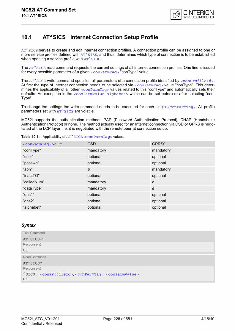
MC52i AT Command Set 10.1 AT^SICS
MC52i_ATC_V01.201 Page 226 of 551 4/16/10Confidential / Released
10.1 AT^SICS Internet Connection Setup Profile
AT^SICS serves to create and edit Internet connection profiles. A connection profile can be assigned to one ormore service profiles defined with AT^SISS, and thus, determines which type of connection is to be establishedwhen opening a service profile with AT^SISO.
The AT^SICS read command requests the current settings of all Internet connection profiles. One line is issuedfor every possible parameter of a given <conParmTag> "conType" value.
The AT^SICS write command specifies all parameters of a connection profile identified by <conProfileId>.At first the type of Internet connection needs to be selected via <conParmTag> value "conType". This deter-mines the applicability of all other <conParmTag> values related to this "conType" and automatically sets theirdefaults. An exception is the <conParmValue-alphabet> which can be set before or after selecting "con-Type".
To change the settings the write command needs to be executed for each single <conParmTag>. All profileparameters set with AT^SICS are volatile.
MC52i supports the authentication methods PAP (Password Authentication Protocol), CHAP (HandshakeAuthentication Protocol) or none. The method actually used for an Internet connection via CSD or GPRS is nego-tiated at the LCP layer, i.e. it is negotiated with the remote peer at connection setup.
Table 10.1: Applicability of AT^SICS <conParmTag> values
Syntax
<conParmTag> value CSD GPRS0
"conType" mandatory mandatory
"user" optional optional
"passwd" optional optional
"apn" ø mandatory
"inactTO" optional optional
"calledNum" mandatory ø
"dataType" mandatory ø
"dns1" optional optional
"dns2" optional optional
"alphabet" optional optional
Test Command
AT^SICS=?Response(s)
OK
Read Command
AT^SICS?Response(s)
^SICS: <conProfileId>, <conParmTag>, <conParmValue>OK

MC52i AT Command Set 10.1 AT^SICS
MC52i_ATC_V01.201 Page 227 of 551 4/16/10Confidential / Released
Parameter Description
0...5 Internet connection profile identifier.The <conProfileId> identifies all parameters of a connection profile, and,when a service profile is created with AT^SISS the <conProfileId> needsto be set as "conId" value of the AT^SISS parameter <srvParmTag>.
Internet connection parameter.
“conType“ Type of Internet connection.For supported values of <conParmValue> refer to <conParmValue-con-Type>.
“alphabet“ Selects the character set for input and output of string parameters within a pro-file. The selected value is bound to the specific profile. This means that differentprofiles may use different alphabets. Unlike other parameters the alphabet canbe changed no matter whether the <conParmTag> value "conType" has beenset. For supported values of <conParmValue> refer to <conParmValue-alphabet>.
“user“ User name string: maximum 32 characters (where "" is default).
“passwd“ Password string: maximum 32 characters (where ***** is default).
“apn“ Access point name string value: maximum 100 characters (where "" is default).
“inactTO“ Inactivity timeout value in seconds: 0 ... 216-1, default = 20Number of seconds the bearer remains open although the service no longerneeds the bearer connection. Do not set the timeout value below 3 sec. This may result in problems whenusing the <eodFlag> (set in the last AT^SISW command to terminate anupload data stream).
“calledNum“ Called BCD number.
“dataType“ Data call type. For supported values of <conParmValue> refer to <conParmValue-dataType>.
“dns1“ Primary DNS server address (IP address in dotted-four-byte format).This value determines whether to use the DNS server addresses dynamicallyassigned by the network or a specific DNS server address given by the user. "dns1" = "0.0.0.0" (default) means that the CSD or GPRS connection profileuses dynamic DNS assignment. Any other address means that the PrimaryDNS is manually set.The default value applies automatically if no other address is set. Note that the
Write Command
AT^SICS=<conProfileId>, <conParmTag>, <conParmValue>Response(s)
OK ERROR +CME ERROR: <err>
PIN ASC0 ASC1 MUX1 MUX2 MUX3 Charge Last
- + + + + + - - -
<conProfileId>(num)
<conParmTag>(str)
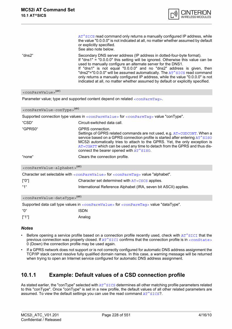
MC52i AT Command Set 10.1 AT^SICS
MC52i_ATC_V01.201 Page 228 of 551 4/16/10Confidential / Released
AT^SICS read command only returns a manually configured IP address, whilethe value "0.0.0.0" is not indicated at all, no matter whether assumed by defaultor explicitly specified. See also note below.
“dns2“ Secondary DNS server address (IP address in dotted-four-byte format).If "dns1" = "0.0.0.0" this setting will be ignored. Otherwise this value can beused to manually configure an alternate server for the DNS1. If "dns1" is not equal "0.0.0.0" and no "dns2" address is given, then"dns2"="0.0.0.0" will be assumed automatically. The AT^SICS read commandonly returns a manually configured IP address, while the value "0.0.0.0" is notindicated at all, no matter whether assumed by default or explicitly specified.
Parameter value; type and supported content depend on related <conParmTag>.
Supported connection type values in <conParmValue> for <conParmTag> value "conType".
“CSD“ Circuit-switched data call.
“GPRS0“ GPRS connection. Settings of GPRS related commands are not used, e.g. AT+CGDCONT. When aservice based on a GPRS connection profile is started after entering AT^SISOMC52i automatically tries to attach to the GPRS. Yet, the only exception isAT+CGATT which can be used any time to detach from the GPRS and thus dis-connect the bearer opened with AT^SISO.
“none“ Clears the connection profile.
Character set selectable with <conParmValue> for <conParmTag> value "alphabet".
[“0“] Character set determined with AT+CSCS applies.
“1“ International Reference Alphabet (IRA, seven bit ASCII) applies.
Supported data call type values in <conParmValue> for <conParmTag> value "dataType".
“0“ ISDN
[“1“] Analog
Notes• Before opening a service profile based on a connection profile recently used, check with AT^SICI that the
previous connection was properly closed. If AT^SICI confirms that the connection profile is in <conState>0 (Down) the connection profile may be used again.
• If a GPRS network does not support or is not correctly configured for automatic DNS address assignment theTCP/IP stack cannot resolve fully qualified domain names. In this case, a warning message will be returnedwhen trying to open an Internet service configured for automatic DNS address assignment.
10.1.1 Example: Default values of a CSD connection profile
As stated earlier, the "conType" selected with AT^SICS determines all other matching profile parameters relatedto this "conType". Once "conType" is set in a new profile, the default values of all other related parameters areassumed. To view the default settings you can use the read command AT^SICS?.
<conParmValue>(str)
<conParmValue-conType>(str)
<conParmValue-alphabet>(str)
<conParmValue-dataType>(str)
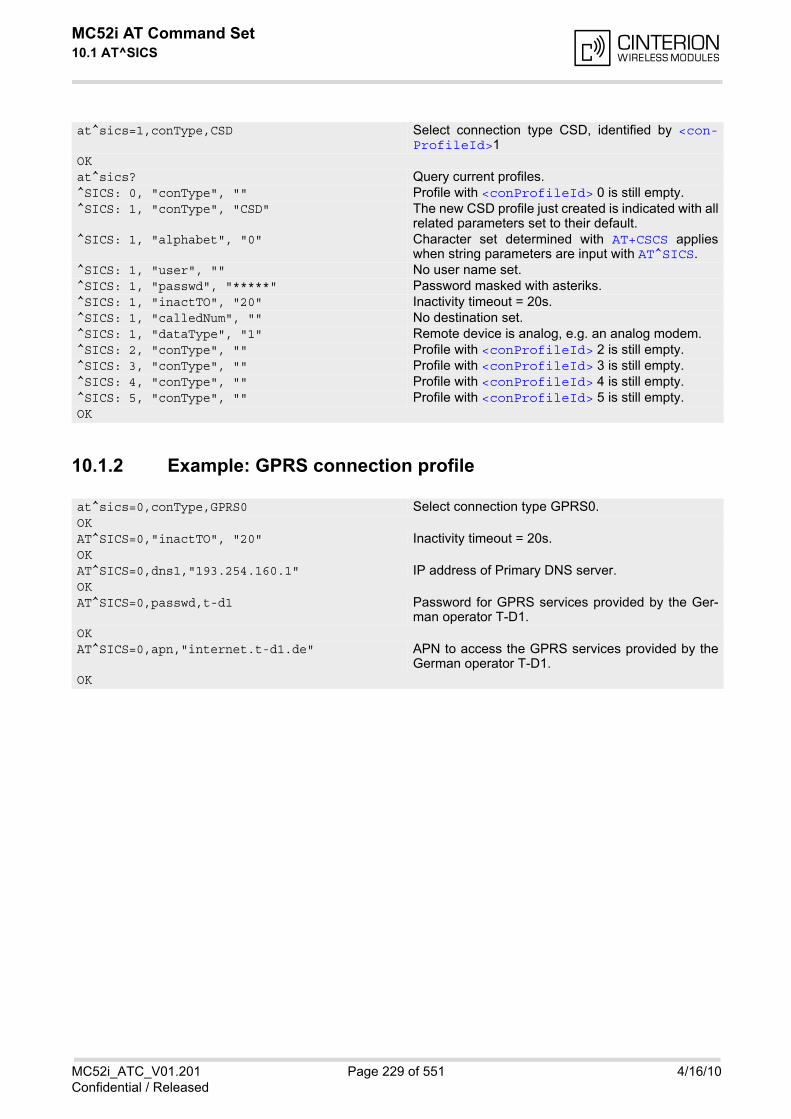
MC52i AT Command Set 10.1 AT^SICS
MC52i_ATC_V01.201 Page 229 of 551 4/16/10Confidential / Released
10.1.2 Example: GPRS connection profile
at^sics=1,conType,CSD Select connection type CSD, identified by <con-ProfileId>1
OKat^sics? Query current profiles.^SICS: 0, "conType", "" Profile with <conProfileId> 0 is still empty.^SICS: 1, "conType", "CSD" The new CSD profile just created is indicated with all
related parameters set to their default.^SICS: 1, "alphabet", "0" Character set determined with AT+CSCS applies
when string parameters are input with AT^SICS.^SICS: 1, "user", "" No user name set.^SICS: 1, "passwd", "*****" Password masked with asteriks.^SICS: 1, "inactTO", "20" Inactivity timeout = 20s.^SICS: 1, "calledNum", "" No destination set.^SICS: 1, "dataType", "1" Remote device is analog, e.g. an analog modem.^SICS: 2, "conType", "" Profile with <conProfileId> 2 is still empty.^SICS: 3, "conType", "" Profile with <conProfileId> 3 is still empty.^SICS: 4, "conType", "" Profile with <conProfileId> 4 is still empty.^SICS: 5, "conType", "" Profile with <conProfileId> 5 is still empty.OK
at^sics=0,conType,GPRS0 Select connection type GPRS0.OKAT^SICS=0,"inactTO", "20" Inactivity timeout = 20s.OKAT^SICS=0,dns1,"193.254.160.1" IP address of Primary DNS server.OKAT^SICS=0,passwd,t-d1 Password for GPRS services provided by the Ger-
man operator T-D1.OKAT^SICS=0,apn,"internet.t-d1.de" APN to access the GPRS services provided by the
German operator T-D1.OK
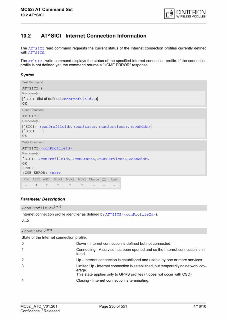
MC52i AT Command Set 10.2 AT^SICI
MC52i_ATC_V01.201 Page 230 of 551 4/16/10Confidential / Released
10.2 AT^SICI Internet Connection Information
The AT^SICI read command requests the current status of the Internet connection profiles currently definedwith AT^SICS.
The AT^SICI write command displays the status of the specified Internet connection profile. If the connectionprofile is not defined yet, the command returns a "+CME ERROR" response.
Syntax
Parameter Description
Internet connection profile identifier as defined by AT^SICS (<conProfileId>).
0...5
State of the Internet connection profile.
0 Down - Internet connection is defined but not connected.
1 Connecting - A service has been opened and so the Internet connection is ini-tated.
2 Up - Internet connection is established and usable by one or more services.
3 Limited Up - Internet connection is established, but temporarily no network cov-erage.This state applies only to GPRS profiles (it does not occur with CSD).
4 Closing - Internet connection is terminating.
Test Command
AT^SICI=?Response(s)
[^SICI:(list of defined <conProfileId>s)]OK
Read Command
AT^SICI?Response(s)
[^SICI: <conProfileId>, <conState>, <numServices>, <conAddr>][^SICI: ...]OK
Write Command
AT^SICI=<conProfileId>Response(s)
^SICI: <conProfileId>, <conState>, <numServices>, <conAddr>OKERROR+CME ERROR: <err>
PIN ASC0 ASC1 MUX1 MUX2 MUX3 Charge Last
- + + + + + - - -
<conProfileId>(num)
<conState>(num)
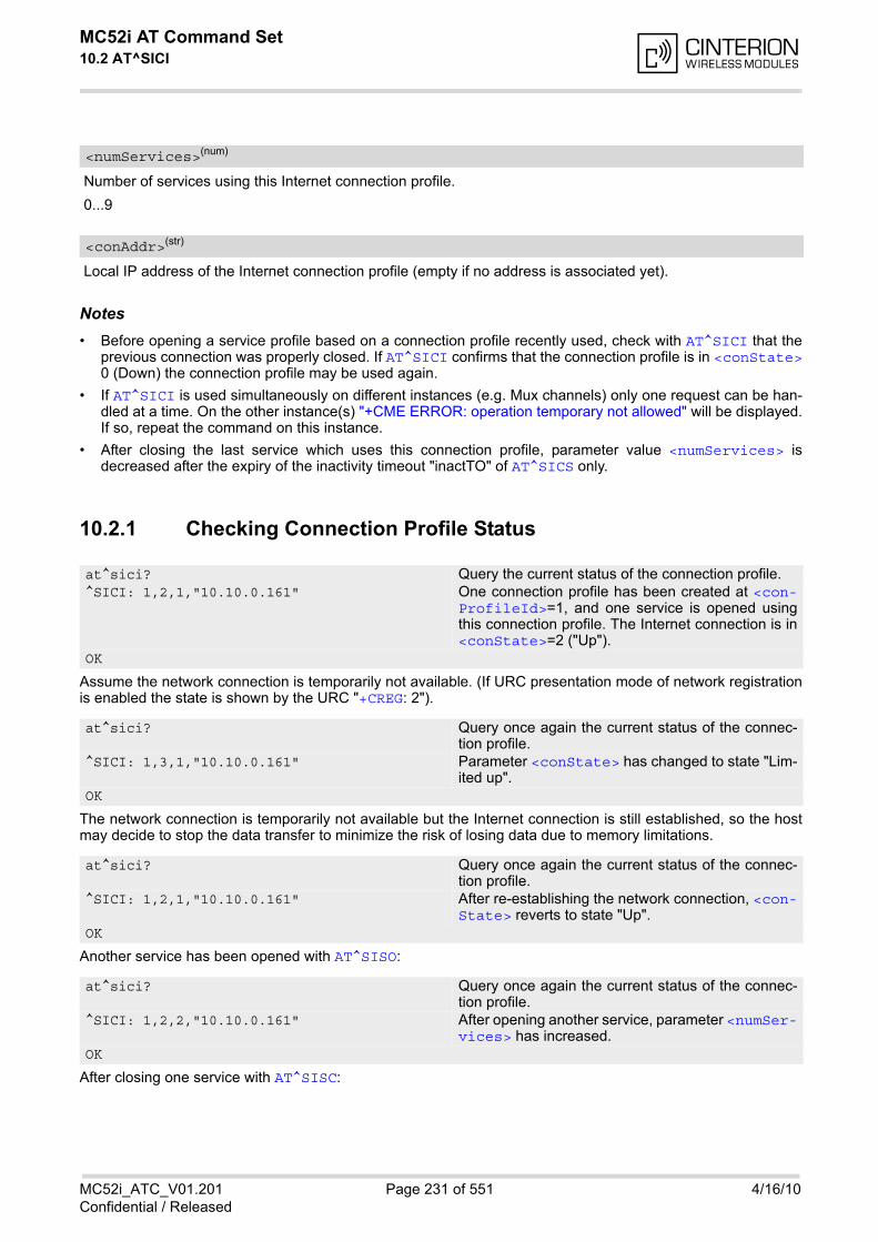
MC52i AT Command Set 10.2 AT^SICI
MC52i_ATC_V01.201 Page 231 of 551 4/16/10Confidential / Released
Number of services using this Internet connection profile.
0...9
Local IP address of the Internet connection profile (empty if no address is associated yet).
Notes• Before opening a service profile based on a connection profile recently used, check with AT^SICI that the
previous connection was properly closed. If AT^SICI confirms that the connection profile is in <conState>0 (Down) the connection profile may be used again.
• If AT^SICI is used simultaneously on different instances (e.g. Mux channels) only one request can be han-dled at a time. On the other instance(s) "+CME ERROR: operation temporary not allowed" will be displayed.If so, repeat the command on this instance.
• After closing the last service which uses this connection profile, parameter value <numServices> isdecreased after the expiry of the inactivity timeout "inactTO" of AT^SICS only.
10.2.1 Checking Connection Profile Status
Assume the network connection is temporarily not available. (If URC presentation mode of network registrationis enabled the state is shown by the URC "+CREG: 2").
The network connection is temporarily not available but the Internet connection is still established, so the hostmay decide to stop the data transfer to minimize the risk of losing data due to memory limitations.
Another service has been opened with AT^SISO:
After closing one service with AT^SISC:
<numServices>(num)
<conAddr>(str)
at^sici? Query the current status of the connection profile.^SICI: 1,2,1,"10.10.0.161" One connection profile has been created at <con-
ProfileId>=1, and one service is opened usingthis connection profile. The Internet connection is in<conState>=2 ("Up").
OK
at^sici? Query once again the current status of the connec-tion profile.
^SICI: 1,3,1,"10.10.0.161" Parameter <conState> has changed to state "Lim-ited up".
OK
at^sici? Query once again the current status of the connec-tion profile.
^SICI: 1,2,1,"10.10.0.161" After re-establishing the network connection, <con-State> reverts to state "Up".
OK
at^sici? Query once again the current status of the connec-tion profile.
^SICI: 1,2,2,"10.10.0.161" After opening another service, parameter <numSer-vices> has increased.
OK
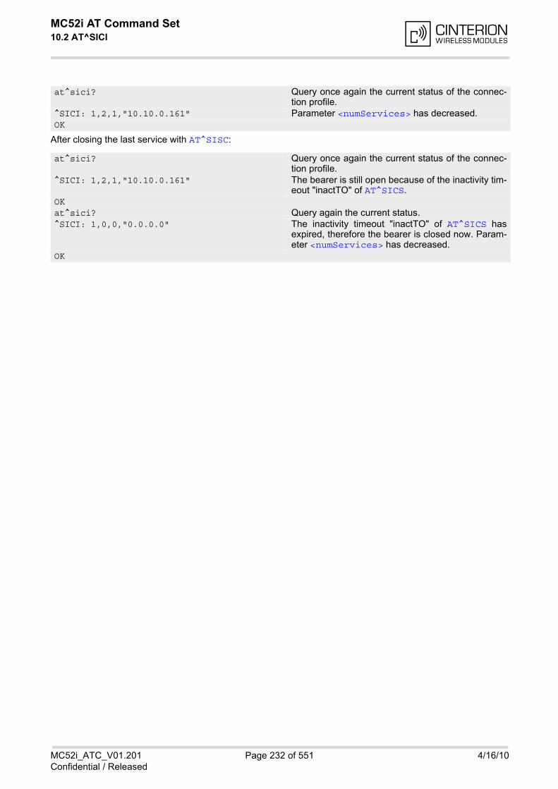
MC52i AT Command Set 10.2 AT^SICI
MC52i_ATC_V01.201 Page 232 of 551 4/16/10Confidential / Released
After closing the last service with AT^SISC:
at^sici? Query once again the current status of the connec-tion profile.
^SICI: 1,2,1,"10.10.0.161" Parameter <numServices> has decreased. OK
at^sici? Query once again the current status of the connec-tion profile.
^SICI: 1,2,1,"10.10.0.161" The bearer is still open because of the inactivity tim-eout "inactTO" of AT^SICS.
OKat^sici? Query again the current status.^SICI: 1,0,0,"0.0.0.0" The inactivity timeout "inactTO" of AT^SICS has
expired, therefore the bearer is closed now. Param-eter <numServices> has decreased.
OK

MC52i AT Command Set 10.3 AT^SISS
MC52i_ATC_V01.201 Page 233 of 551 4/16/10Confidential / Released
10.3 AT^SISS Internet Service Setup Profile
AT^SISS serves to set up the necessary parameters in the Internet service profiles. Any service profile can thenbe used to control a data link in conjunction with AT^SISI, AT^SISO, AT^SISC, AT^SISR, AT^SISW, AT^SISTand AT^SISE.
The AT^SISS read command requests the current settings of all Internet service profiles. One line is issued forevery possible parameter of a given <srvParmTag> "srvType" value.
The AT^SISS write command specifies the parameters for a service profile identified by <srvProfileId>. Atfirst the type of Internet service needs to be selected via <srvParmTag> value "srvType". This determines theapplicability of all other <srvParmTag> values related to this "srvType" and sets their defaults. Changing the<srvParmTag> "srvType" of an existing service profile will reset all <srvParmTag> default values to suit thenew "srvType". An exception is the <srvParmValue-alphabet> which can be set before or after selecting"srvType" and is not reset when "srvType" changes.
To change the settings the write command needs to be executed for each single <srvParmTag>. All profileparameters set with AT^SISS are volatile.
The list below shows which <srvParmTag> parameters apply to each Internet service and which of them aremandatory or optional.
Table 10.2: Applicability of AT^SISS <srvParmTag> values
<srvParmTag> Mandatory or optional
Socket service
"srvType" mandatory
"conId" mandatory
"alphabet" optional
"address" mandatory
"tcpMR" optional
"tcpOT" optional
Transparent service
"srvType" mandatory
"conId" mandatory
"alphabet" optional
"address" mandatory
"tcpMR" optional
"tcpOT" optional
FTP service
"srvType" mandatory
"conId" mandatory
"alphabet" optional
"address" mandatory
"tcpMR" optional
"tcpOT" optional
HTTP service
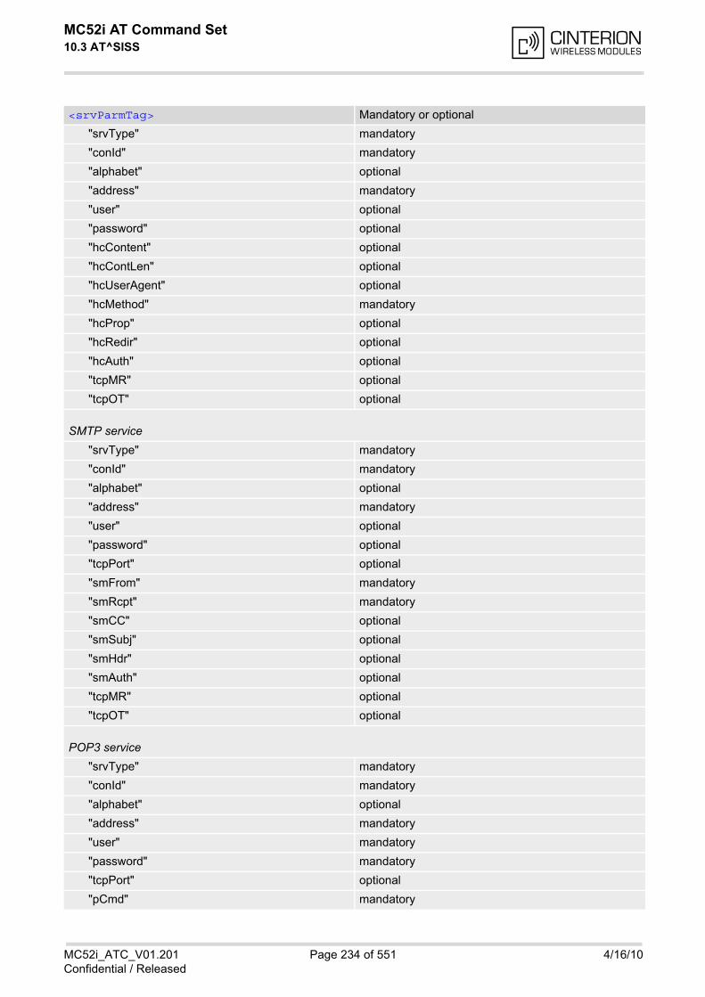
MC52i AT Command Set 10.3 AT^SISS
MC52i_ATC_V01.201 Page 234 of 551 4/16/10Confidential / Released
"srvType" mandatory
"conId" mandatory
"alphabet" optional
"address" mandatory
"user" optional
"password" optional
"hcContent" optional
"hcContLen" optional
"hcUserAgent" optional
"hcMethod" mandatory
"hcProp" optional
"hcRedir" optional
"hcAuth" optional
"tcpMR" optional
"tcpOT" optional
SMTP service
"srvType" mandatory
"conId" mandatory
"alphabet" optional
"address" mandatory
"user" optional
"password" optional
"tcpPort" optional
"smFrom" mandatory
"smRcpt" mandatory
"smCC" optional
"smSubj" optional
"smHdr" optional
"smAuth" optional
"tcpMR" optional
"tcpOT" optional
POP3 service
"srvType" mandatory
"conId" mandatory
"alphabet" optional
"address" mandatory
"user" mandatory
"password" mandatory
"tcpPort" optional
"pCmd" mandatory
<srvParmTag> Mandatory or optional
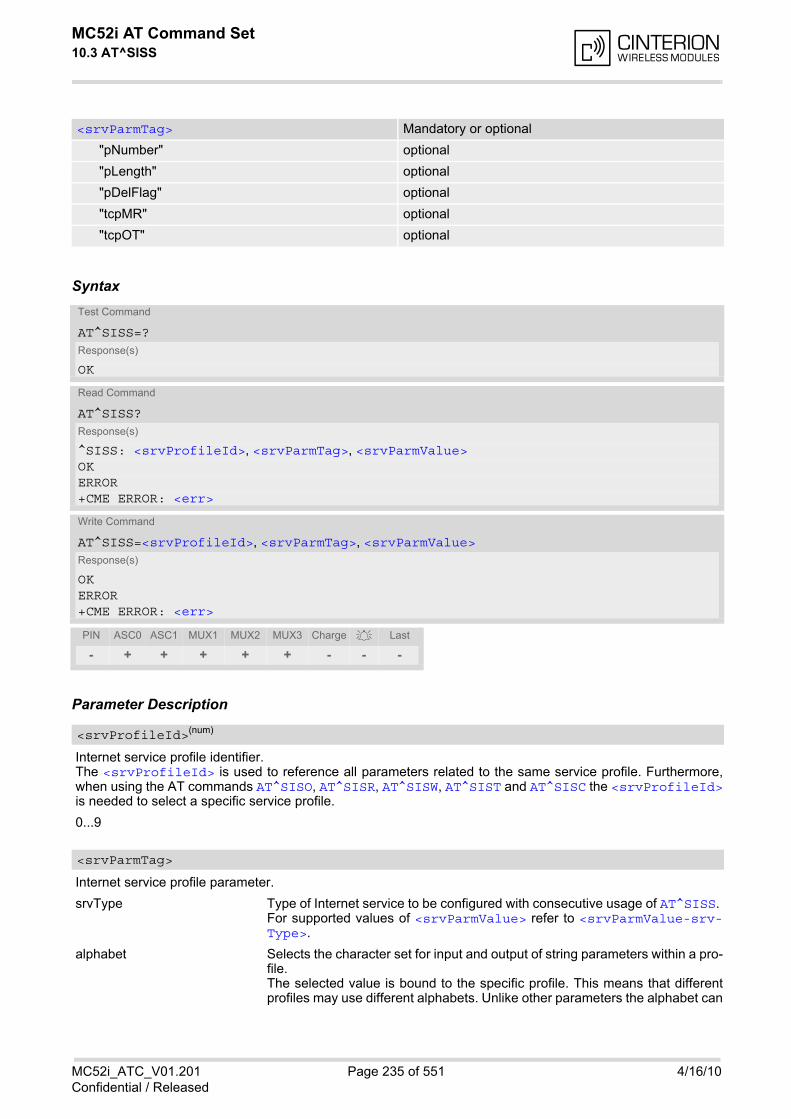
MC52i AT Command Set 10.3 AT^SISS
MC52i_ATC_V01.201 Page 235 of 551 4/16/10Confidential / Released
Syntax
Parameter Description
Internet service profile identifier.The <srvProfileId> is used to reference all parameters related to the same service profile. Furthermore,when using the AT commands AT^SISO, AT^SISR, AT^SISW, AT^SIST and AT^SISC the <srvProfileId>is needed to select a specific service profile.
0...9
Internet service profile parameter.
srvType Type of Internet service to be configured with consecutive usage of AT^SISS. For supported values of <srvParmValue> refer to <srvParmValue-srv-Type>.
alphabet Selects the character set for input and output of string parameters within a pro-file. The selected value is bound to the specific profile. This means that differentprofiles may use different alphabets. Unlike other parameters the alphabet can
"pNumber" optional
"pLength" optional
"pDelFlag" optional
"tcpMR" optional
"tcpOT" optional
Test Command
AT^SISS=?Response(s)
OK
Read Command
AT^SISS?Response(s)
^SISS: <srvProfileId>, <srvParmTag>, <srvParmValue>OKERROR+CME ERROR: <err>
Write Command
AT^SISS=<srvProfileId>, <srvParmTag>, <srvParmValue>Response(s)
OK ERROR +CME ERROR: <err>
PIN ASC0 ASC1 MUX1 MUX2 MUX3 Charge Last
- + + + + + - - -
<srvProfileId>(num)
<srvParmTag>
<srvParmTag> Mandatory or optional
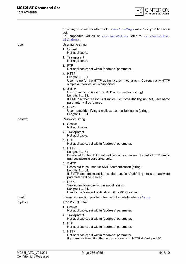
MC52i AT Command Set 10.3 AT^SISS
MC52i_ATC_V01.201 Page 236 of 551 4/16/10Confidential / Released
be changed no matter whether the <srvParmTag> value "srvType" has beenset. For supported values of <srvParmValue> refer to <srvParmValue-alphabet>.
user User name string
1. Socket Not applicable.
2. Transparent Not applicable.
3. FTP Not applicable; set within "address" parameter.
4. HTTPLength: 2 ... 31User name for the HTTP authentication mechanism. Currently only HTTPsimple authentication is supported.
5. SMTP User name to be used for SMTP authentication (string).Length: 4 ... 64. If SMTP authentication is disabled, i.e. "smAuth" flag not set, user nameparameter will be ignored.
6. POP3 User name identifying a mailbox, i.e. mailbox name (string).Length: 1 ... 64.
passwd Password string
1. Socket Not applicable.
2. Transparent Not applicable.
3. FTP Not applicable; set within "address" parameter.
4. HTTP Length: 2 ... 31Password for the HTTP authentication mechanism. Currently HTTP simpleauthentication is supported only.
5. SMTP Password to be used for SMTP authentication (string).Length: 4 ... 64. If SMTP authentication is disabled, i.e. "smAuth" flag not set, passwordparameter will be ignored.
6. POP3 Server/mailbox-specific password (string).Length: 1 ... 64. Used to perform authentication with a POP3 server.
conId Internet connection profile to be used, for details refer AT^SICS.
tcpPort TCP Port Number
1. Socket Not applicable; set within "address" parameter.
2. Transparent Not applicable; set within "address" parameter.
3. FTP Not applicable; set within "address" parameter.
4. HTTP Not applicable; set within "address" parameter. If parameter is omitted the service connects to HTTP default port 80.
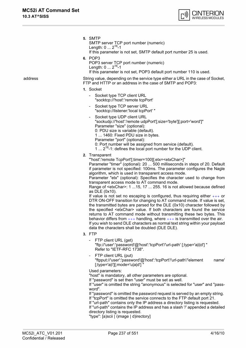
MC52i AT Command Set 10.3 AT^SISS
MC52i_ATC_V01.201 Page 237 of 551 4/16/10Confidential / Released
5. SMTP SMTP server TCP port number (numeric) Length: 0 ... 216-1If this parameter is not set, SMTP default port number 25 is used.
6. POP3 POP3 server TCP port number (numeric)Length: 0 ... 216-1If this parameter is not set, POP3 default port number 110 is used.
address String value, depending on the service type either a URL in the case of Socket,FTP and HTTP or an address in the case of SMTP and POP3:
1. Socket
- Socket type TCP client URL "socktcp://'host':'remote tcpPort'
- Socket type TCP server URL "socktcp://listener:'local tcpPort' "
- Socket type UDP client URL "sockudp://'host':'remote udpPort'[;size='byte'][;port='word']" Parameter "size" (optional): 0: PDU size is variable (default). 1 ... 1460: Fixed PDU size in bytes.Parameter "port" (optional):0: Port number will be assigned from service (default).1 ... 216-1: defines the local port number for the UDP client.
2. Transparent "'host':'remote TcpPort'[;timer=100][;etx=<etxChar>]" Parameter "timer" (optional): 20 ... 500 milliseconds in steps of 20. Defaultif parameter is not specified: 100ms. The parameter configures the Naglealgorithm, which is used in transparent access mode.Parameter "etx" (optional): Specifies the character used to change fromtransparent access mode to AT command mode. Range of <etxChar>: 1 ...15, 17 ... 255. 16 is not allowed because definedas DLE (0x10). If value is not set no escaping is configured, thus requiring either +++ orDTR ON-OFF transition for changing to AT command mode. If value is set,the transmitted bytes are parsed for the DLE (0x10) character followed bythe specified <etxChar> value. If both characters are found the servicereturns to AT command mode without transmitting these two bytes. Thisbehavior differs from +++ handling, where +++ is transmitted over the air.If you wish to send DLE characters as normal text string within your payloaddata the characters shall be doubled (DLE DLE).
3. FTP
- FTP client URL (get)"ftp://'user':'password'@'host':'tcpPort'/'url-path' [;type='a|i|d'] "Refer to "IETF-RFC 1738".
- FTP client URL (put)"ftpput://'user':'password'@'host':'tcpPort'/'url-path'/'element name'[;type='a|i'][;mode='u|a|d'] "
Used parameters:"host" is mandatory, all other parameters are optional. If "password" is set then "user" must be set as well. If "user" is omitted the string "anonymous" is selected for "user" and "pass-word". If "password" is omitted the password request is served by an empty string. If "tcpPort" is omitted the service connects to the FTP default port 21. If "url-path" contains only the IP address a directory listing is requested. If "url-path" contains the IP address and has a slash '/' appended a detaileddirectory listing is requested. "type": [a)scii | i)mage | d)irectory]
MC52i AT Command Set 10.3 AT^SISS
MC52i_ATC_V01.201 Page 238 of 551 4/16/10Confidential / Released
"mode": [u)nique | a)ppend | d)elete] "u)nique" selects the FTP Store Unique command to create a file nameunique to the current directory. If the file name is assigned by the serverthen the "^SIS" URC will appear, indicating <urcInfoId> 2100 and thefile name. "d)elete" clears given 'element name'. If "mode" is omitted "replace mode" is default setting.
4. HTTPHTTP client URLLength: 6 ... 255"http://'server'/'path':'tcpPort' ""server": FQDN or IP-address "path": path of file or directory "tcpPort": If parameter is omitted the service connects to HTTP default port80. Refer to "IETF-RFC 2616".
5. SMTP SMTP server address (string). Length: 4 ... 256.
6. POP3 POP3 server address (string). Length: 4 ... 256.
hcContent Optional parameter for HTTP method "Post".Length: 0 ... 127Can be used to transfer a small amount of data. The content of this string willonly be sent if "hcContLen" = 0. The maximum length of "hcContent" is 127bytes. To transmit a larger amount of data "hcContLen" must be set to a non-zerovalue. In this case the "hcContent" string will be ignored, and data transmissionfrom the client to the server is done with AT^SISW.
hcContLen Mandatory parameter for HTTP method "Post".Length: 0 ... 231-1The content length shall be set in the header of the HTTP "Post" request beforethe data part is transferred.If "hcContLen" = 0 then the data given in the "hcContent" string will be posted.If "hcContLen" > 0 then the AT^SISW command will be used to send data fromthe client to the server. In this case, "hcContLen" specifies the total amount ofdata to be sent. The data can be sent in one or several parts. For each part,the transmission is triggered by the URC "^SISW: x, 1", then the AT^SISW writecommand can be executed. After the exact number of bytes are transferred viathe serial interface, the HTTP client will go from service state "Up" to servicestate "Closing" (see parameters <srvState> and <srvState> for detail).Finally, the URC "^SISW: x, 2" indicates that all data have been transferred andthe service can be closed with AT^SISC.
hcUsrAgent The user agent string must be set by the application to identify the mobile. Usu-ally operation system and software version info is set with this browser identi-fier. Length: 0 ... 63
hcMethod HTTP method specification: 0=GET, 1=POST, 2=HEAD.
hcProp Parameter for several HTTP settings. Length: 0 ... 127The general format is 'key': <space> 'value' Multiple settings can be given separated by "\0d\0a" sequences within thestring, do not put them at the end. Possible 'key' values are defined at HTTP/1.1 Standard RFC 2616.
MC52i AT Command Set 10.3 AT^SISS
MC52i_ATC_V01.201 Page 239 of 551 4/16/10Confidential / Released
hcRedir This flag controls the redirection mechanism of the MC52i acting as HTTP cli-ent (numeric).If "hcRedir" = 0: No redirection.If "hcRedir" = 1: The client automatically sends a new HTTP request if theserver answers with a redirect code (range 30x).Default is 1.
hcAuth If set ("hcAuth" = 1) this flag determines that the HTTP client will automaticallyanswer on authentication requests from the server with the current "passwd"and "user" parameter settings. If these parameters are not specified the MC52iwill terminate the HTTP connection and send an indication to the TA.Default is 1.
smFrom Email sender address, i.e. "MAIL FROM" address (string). Length: 6 ... 256A valid address parameter consists of local part and domain name delimited bya '@' character, e.g. "[email protected]".
smRcpt Recipient address of the email, i.e. "RCPT TO" address (string). Length: 6 ... 256If multiple recipient addresses are to be supplied the comma character is usedas delimiter to separate individual address values, e.g. "[email protected],[email protected]". Some mail servers do not accept recip-ient addresses without brackets <>. It is recommended to use the "RCPT TO"variable with brackets.
smCC CC recipient address of the email (string). Length: 6 ... 256If multiple CC recipient addresses are to be supplied the comma character isused as delimiter to separate individual address values, e.g."[email protected],[email protected]".
smSubj Subject content of the email (string).Length: 0 ... 256If no subject is supplied the email will be sent with an empty subject.
smHdr This parameter, if set, will be appended at the end of the email header section(string).Length: 0... 256Hence, it serves as a generic header field parameter which allows the user toprovide any email header field. It is the user's responsibility to provide correctheader fields!String of max. 256 characters. Example for multipart MIME messages: "Content-Type: multipart/mixed".
smAuth SMTP authentication control flag (numeric). If disabled (<srvParmValue> "0" by default), MC52i performs action withoutSMTP authentication. If enabled (<srvParmValue> "1") authentication procedure with the SMTPserver will be performed by means of supported authentication methods, usingvalues of "user" and "passwd" parameters. If MC52i and SMTP server are notable to negotiate an authentication mechanism supported by both parties, theMC52i continues action without authentication.MC52i supports SMTP authentication.
pCmd POP3 user command to be executed by the POP3 service (numeric). For supported values of <srvParmValue> refer to <srvParmValue-pCmd>.
pNumber Optional message number argument used by the POP3 commands List ("2"),Retrieve ("3") and Delete ("4"). For POP3 commands see <srvParmTag>value "pCmd". Length: 0 ... 231-1If no specific value is set in the service profile, the value "0" is assumed bydefault, i.e. "pNumber" is disabled.
MC52i AT Command Set 10.3 AT^SISS
MC52i_ATC_V01.201 Page 240 of 551 4/16/10Confidential / Released
pLength Maximum message length (string, optional)Length: 0 ... 231-1"pLength" can be used to specify the length of the message(s) to be retrievedfrom or deleted on the POP3 server. If no specific value is set in the serviceprofile, the default value "0" is assumed, which means that there is no limit onthe message size. A warning will be issued inthe following cases:
• If "pNumber" > 0 and a specific message to be retrieved from / deleted onthe server is longer than "pLength".
• If "pNumber" = 0 and all messages to be retrieved from / deleted on theserver are longer than "pLength".
No warning will be issued in the following cases:
• If there are no messages at all on the server.
• If the server has message(s) below and above the "pLength" specified. Inthis case, the message(s) within the range of "pLength" can be successfullyretrieved or deleted, but the message(s) above "pLength" remain on theserver without any further notification given to the user.
• Therefore, after retrieving / deleting messages, it is recommended to checkthe message status on the server. This can be done by adding a furtherPOP3 service profile using the POP3 user command List ("2").
pDelFlag Flag to be used with the POP3 user command Retrieve ("3"). Specifies whetheror not to delete retrieved emails on the server (optional). For supported values of <srvParmValue> refer to <srvParmValue-pDelFlag>.
tcpMR Parameter can be used to overwrite the global AT^SCFG parameter "Tcp/MaxRetransmissions" <tcpMr> for a specific Internet Service connection pro-file. If the parameter is not specified the value specified with AT^SCFG will beused. Supported values <srvParmValue> for this parameter are the same asdescribed for <tcpMr>. Setting is not relevant for Internet Service "Socket" with type "UDP".
tcpOT Parameter can be used to overwrite the global AT^SCFG parameter "Tcp/Over-allTimeout" <tcpOt> for a specific Internet Service connection profile. If theparameter is not specified the value specified with AT^SCFG will be used. Supported values <srvParmValue> for this parameter are the same asdescribed for <tcpOt>. Setting is not relevant for Internet Service "Socket" with type "UDP".
Parameter value; type and supported content depend on related <srvParmTag>.
Supported Internet service type values in <srvParmValue> for <srvParmTag> value "srvType".Before changing the "srvType" of an existing service profile be sure that the profile is closed. To verify the con-nection state of the service profile enter the read command AT^SISI. Only when <srvState>=2 is returnedfor this specific service profile you can change its service type.
“Socket“ MC52i acting as client or server (listener) for TCP or UDP.If MC52i is TCP listener at least two service profiles are required. The firstsocket profile must be configured as listener. The second service profile will bedynamically assigned when a socket connection request from a remote clientis incoming. For this purpose, one service profile must be left free (= not con-figured with AT^SISS). An incoming socket connection request will be indi-cated by the "^SIS" URC, with the next free <srvProfileId> shown insidethe URC as parameter <urcInfoId>. The connection request can beaccepted or rejected by using the commands AT^SISO or AT^SISC and the IDretrieved from the "^SIS".
<srvParmValue>(str)
<srvParmValue-srvType>(str)
MC52i AT Command Set 10.3 AT^SISS
MC52i_ATC_V01.201 Page 241 of 551 4/16/10Confidential / Released
“Transparent“ MC52i acting as Transparent TCP socket client.
“Ftp“ MC52i acting as FTP client.
“Http“ MC52i acting as HTTP client.
“Smtp“ MC52i acting as SMTP client.
“Pop3“ MC52i acting as POP3 client.
“none“ Reset Internet service profile settings. Operation is not allowed if profile is inuse, i.e. it was activated via AT^SISO.
Supported string parameter character set selections in <srvParmValue> for <srvParmTag> value "alphabet".
[“0“] Applicable character set is determined by current setting of AT+CSCS.
“1“ International Reference Alphabet (IRA, seven bit ASCII).
Supported POP3 user command values in <srvParmValue> for <srvParmTag> value "pCmd".
1 Status command. This command retrieves the "drop listing" of a POP3 server. A "drop listing"consists of a single line containing the number of messages in the maildrop listfollowed by the total size of the maildrop list in bytes. Each drop listing will befinished by a so-called "dotline", i.e. a new line with just a single dot.
2 List command. If <srvParmTag> value "pNumber" is set to a non-zero value the "List" com-mand returns the "scan listing", consisting of a single line which contains themessage number and the message size in bytes if the specified messageexists in the maildrop list on the POP3 server. If no such message exists on the server than the POP3 service issues an errorresponse to the user. If <srvParmTag> value "pNumber" is zero the "List" command returns a multi-line "scan listing". For each message on the maildrop list of the server thePOP3 service returns a line containing the message number and its size inbytes. A final "dotline" will be printed at the end of the "scan listing". If there are no messages on the maildrop list of the server, the POP3 servicereturns a positive response, i.e. it doesn't issue an error response, but the"scan listing" will be empty.In either case, each scan listing will be finished by a so-called "dotline", i.e. anew line with just a single dot.
3 Retrieve command. If <srvParmTag> value "pNumber" is set to a non-zero value this commandretrieves the related message from the POP3 server's maildrop list. If no such message exists on the server the POP3 service issues an errorresponse to the user. It depends on the parameter "pDelFlag" if the message will be deleted from thePOP3 server upon successful retrieval. If <srvParmTag> value "pNumber" is zero the "Retrieve" command returns allmessages pending in the POP3 server's maildrop. If there are no messages on the maildrop list of the server the POP3 servicereturns with a positive response, i.e. it doesn't issue an error response, but thereturned list will be empty.Each email will be finished by a so-called "dotline", i.e. a new line with just asingle dot.
4 Delete commandIf <srvParmTag> value "pNumber" is set to a non-zero value the commanddeletes the related message from the POP3 server's maildrop list. In fact, themessage is marked as deleted on the server and will be deleted permanentlyif the POP3 service command executes successfully. In case an error has
<srvParmValue-alphabet>(str)
<srvParmValue-pCmd>(num)

MC52i AT Command Set 10.3 AT^SISS
MC52i_ATC_V01.201 Page 242 of 551 4/16/10Confidential / Released
occurred, e.g. network loss, the message will not be deleted on the server eventhough the POP3 service command has been finished. If <srvParmTag> value "pNumber" is zero the "Delete" command deletes allmessages from the POP3 server's maildrop list. In fact, the messages aremarked as deleted on the server and will be deleted permanently if the POP3service command executes successfully. In case an error has occurred, themessages will not be deleted on the server even though the POP3 servicecommand has been finished.
Supported flag values in <srvParmValue> for <srvParmTag> value "pDelFlag". Only applicable if the profilecontains the POP3 user command Retrieve ("3").
[0] Messages will not be deleted on the server.
1 Delete messages on the server which have been retrieved successfully.
Notes• String parameters are truncated if greater than the maximum length specified above.
• If AT^SISS is used simultaneously on different instances (e.g. Mux channels) only one request can be han-dled at a time. On the other instance(s) "+CME ERROR: operation temporary not allowed" will be displayed.If so, repeat the command on this instance.
<srvParmValue-pDelFlag>(num)
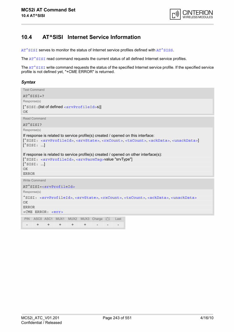
MC52i AT Command Set 10.4 AT^SISI
MC52i_ATC_V01.201 Page 243 of 551 4/16/10Confidential / Released
10.4 AT^SISI Internet Service Information
AT^SISI serves to monitor the status of Internet service profiles defined with AT^SISS.
The AT^SISI read command requests the current status of all defined Internet service profiles.
The AT^SISI write command requests the status of the specified Internet service profile. If the specified serviceprofile is not defined yet, "+CME ERROR" is returned.
SyntaxTest Command
AT^SISI=?Response(s)
[^SISI:(list of defined <srvProfileId>s)]OK
Read Command
AT^SISI?Response(s)
If response is related to service profile(s) created / opened on this interface:[^SISI: <srvProfileId>, <srvState>, <rxCount>, <txCount>, <ackData>, <unackData>][^SISI: ...]
If response is related to service profile(s) created / opened on other interface(s):[^SISI: <srvProfileId>, <srvParmTag>value "srvType"][^SISI: ...]OKERROR
Write Command
AT^SISI=<srvProfileId>Response(s)
^SISI: <srvProfileId>, <srvState>, <rxCount>, <txCount>, <ackData>, <unackData>OKERROR+CME ERROR: <err>
PIN ASC0 ASC1 MUX1 MUX2 MUX3 Charge Last
- + + + + + - - -

MC52i AT Command Set 10.4 AT^SISI
MC52i_ATC_V01.201 Page 244 of 551 4/16/10Confidential / Released
Parameter Description
Internet service profile identifier as defined by AT^SISS (<srvProfileId>).
0...9
Internet service state (for details see AT^SISO parameter <srvState>).
2 Allocated
3 Connecting
4 Up
5 Closing
6 Down
Number of bytes received via AT^SISR or AT^SIST since last successful AT^SISO write command. This is the same value as displayed by the AT^SISO read command with the parameter <rxCount>.
Number of bytes sent via AT^SISW or AT^SIST since last successful AT^SISO write command. This is the same value as displayed by the AT^SISO read command with the parameter <txCount>.
Number of data bytes already sent and acknowledged at TCP layer. Value 0 indicates that no sent data isacknowledged yet. Parameter is not applicable to HTTP, POP3, SMTP and Socket with UDP. For these services the counter isalways set to 0.
Number of data bytes already sent but not yet acknowledged at TCP layer. A value 0 indicates that all sent datais already acknowledged. This is the same value as displayed in the response of the AT^SISW write command with the parameter<unackData>. Parameter is not applicable to HTTP, POP3, SMTP and Socket with UDP. For these services the counter isalways set to 0.
Note• If a service is in state "Down" the responses for <rxCount>, <txCount>, <ackData> and <unackData>
are the last known values for the service in the states "Connecting", "Up" and "Closing".
<srvProfileId>(num)
<srvState>(num)
<rxCount>(num)
<txCount>(num)
<ackData>(num)
<unackData>(num)

MC52i AT Command Set 10.5 AT^SISO
MC52i_ATC_V01.201 Page 245 of 551 4/16/10Confidential / Released
10.5 AT^SISO Internet Service Open
The AT^SISO write command starts the Internet session configured by the service profile. All further stepsneeded to control the session depend on whether you are using URC mode or polling mode. The AT^SISO readcommand returns the current status of all services.
URC mode:If the service opens successfully, the URCs "^SISW" and "^SISR" will trigger the action to follow, either writingdata with AT^SISW or reading data with AT^SISR. To terminate an upload data stream set the <eodFlag>within the last AT^SISW command. If the URCs notify that a data transfer has been successful ("^SISR: x, 2" or"^SISW: x, 2"), the service can be closed with AT^SISC. If a special event occurs, e.g. an error or a warning,after opening or while using a service then the URC type "^SIS" will be delivered.
Polling mode:After opening the service, all progress information needed to control the session shall be explicitly requested bythe host application. The particular sequence of AT commands varies depending on the service used. The fol-lowing list summarizes, by way of an example, the steps normally involved in managing an upload or downloadjob.
• Upload (Socket, FTP, HTTP, SMTP):
- Enter the AT^SISO command, e.g. AT^SISO=9.
- Enter AT^SISW, specify <reqWriteLength>, e.g. AT^SISW=9,20. Check resulting response for <cnf-WriteLength>. Optionally, check error with AT^SISE, e.g. AT^SISE=9. If necessary, repeat thesequence several times.
- Enter last AT^SISW command and enable <eodFlag>, e.g. AT^SISW=9,0,1. If Socket service: Query available data with AT^SISR, e.g. AT^SISR=9,1430.
- Check service state with AT^SISI, e.g. AT^SISI=9, if necessary several times until <srvState>=6("Down").
- Check error with AT^SISE, e.g. AT^SISE=9.
- Close service with AT^SISC, e.g. AT^SISC=9.
• Download (Socket, FTP, HTTP, POP3):
- Enter the AT^SISO command, e.g. AT^SISO=9.
- Enter AT^SISR, specify <reqReadLength>, e.g. AT^SISR=9,1000. Check resulting response for<cnfReadLength>. If necessary, repeat the sequence several times until <cnfReadLength>= -2 (endof data) or ERROR.
- Check error with AT^SISE, e.g. AT^SISE=9.
- Close service with AT^SISC, e.g. AT^SISC=9.
• Socket service (upload and download possible in one session):
- Recommended: Set AT+CMEE=2 to enable extended error text.
- Enter the AT^SISO command, e.g. AT^SISO=9.
- Enter AT^SISR or AT^SISW, specifying <reqReadLength> or <reqWriteLength>, e.g.AT^SISR=9,20 or AT^SISW=9,20. Check resulting response for <cnfReadLength> or <cnfWrite-Length>. If necessary, repeat the sequence several times.
- Check error with AT^SISE, e.g. AT^SISE=9.
- If write action: Enter last AT^SISW command and enable <eodFlag>, e.g. AT^SISW=9,0,1. 1) If Socket service: Query available data with AT^SISR, e.g. AT^SISR=9,1430.
- Close service with AT^SISC, e.g. AT^SISC=9.
• Transparent TCP service:
- Enter the AT^SISO command, e.g. AT^SISO=9.
- Enter AT^SIST to enter transparent data mode. After communication has finished return to AT commandmode via +++ escape sequence.
- Check error with AT^SISE, e.g. AT^SISE=9.
- Close service with AT^SISC, e.g. AT^SISC=9.
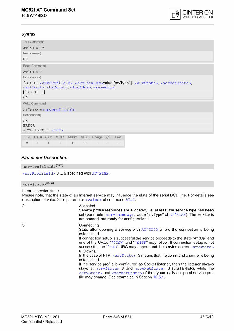
MC52i AT Command Set 10.5 AT^SISO
MC52i_ATC_V01.201 Page 246 of 551 4/16/10Confidential / Released
Syntax
Parameter Description
<srvProfileId> 0 ... 9 specified with AT^SISS.
Internet service state. Please note, that the state of an Internet service may influence the state of the serial DCD line. For details seedescription of value 2 for parameter <value> of command AT&C.
2 Allocated Service profile resources are allocated, i.e. at least the service type has beenset (parameter <srvParmTag>, value "srvType" of AT^SISS). The service isnot opened, but ready for configuration.
3 Connecting State after opening a service with AT^SISO where the connection is beingestablished. If connection setup is successful the service proceeds to the state "4" (Up) andone of the URCs "^SISW" and "^SISR" may follow. If connection setup is notsuccessful, the "^SIS" URC may appear and the service enters <srvState>6 (Down). In the case of FTP, <srvState>=3 means that the command channel is beingestablished.If the service profile is configured as Socket listener, then the listener alwaysstays at <srvState>=3 and <socketState>=3 (LISTENER), while the<srvState> and <socketState> of the dynamically assigned service pro-file may change. See examples in Section 10.5.1.
Test Command
AT^SISO=?Response(s)
OK
Read Command
AT^SISO?Response(s)
^SISO: <srvProfileId>, <srvParmTag>value "srvType" [, <srvState>, <socketState>, <rxCount>, <txCount>, <locAddr>, <remAddr>][^SISO: ...]OK
Write Command
AT^SISO=<srvProfileId>Response(s)
OK ERROR +CME ERROR: <err>
PIN ASC0 ASC1 MUX1 MUX2 MUX3 Charge Last
± + + + + + - - -
<srvProfileId>(num)
<srvState>(num)
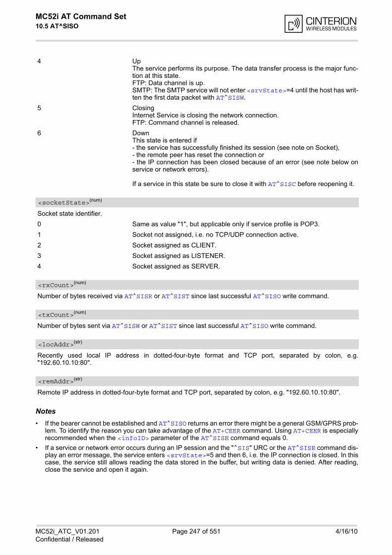
MC52i AT Command Set 10.5 AT^SISO
MC52i_ATC_V01.201 Page 247 of 551 4/16/10Confidential / Released
4 Up The service performs its purpose. The data transfer process is the major func-tion at this state.FTP: Data channel is up.SMTP: The SMTP service will not enter <srvState>=4 until the host has writ-ten the first data packet with AT^SISW.
5 Closing Internet Service is closing the network connection.FTP: Command channel is released.
6 Down This state is entered if - the service has successfully finished its session (see note on Socket), - the remote peer has reset the connection or - the IP connection has been closed because of an error (see note below onservice or network errors).
If a service in this state be sure to close it with AT^SISC before reopening it.
Socket state identifier.
0 Same as value "1", but applicable only if service profile is POP3.
1 Socket not assigned, i.e. no TCP/UDP connection active.
2 Socket assigned as CLIENT.
3 Socket assigned as LISTENER.
4 Socket assigned as SERVER.
Number of bytes received via AT^SISR or AT^SIST since last successful AT^SISO write command.
Number of bytes sent via AT^SISW or AT^SIST since last successful AT^SISO write command.
Recently used local IP address in dotted-four-byte format and TCP port, separated by colon, e.g."192.60.10.10:80".
Remote IP address in dotted-four-byte format and TCP port, separated by colon, e.g. "192.60.10.10:80".
Notes• If the bearer cannot be established and AT^SISO returns an error there might be a general GSM/GPRS prob-
lem. To identify the reason you can take advantage of the AT+CEER command. Using AT+CEER is especiallyrecommended when the <infoID> parameter of the AT^SISE command equals 0.
• If a service or network error occurs during an IP session and the "^SIS" URC or the AT^SISE command dis-play an error message, the service enters <srvState>=5 and then 6, i.e. the IP connection is closed. In thiscase, the service still allows reading the data stored in the buffer, but writing data is denied. After reading,close the service and open it again.
<socketState>(num)
<rxCount>(num)
<txCount>(num)
<locAddr>(str)
<remAddr>(str)
MC52i AT Command Set 10.5 AT^SISO
MC52i_ATC_V01.201 Page 248 of 551 4/16/10Confidential / Released
• As in polling mode no error URCs are available you are advised to integrate the commands AT^SISI andAT^SISE into the command sequences for upload and download jobs. So, the AT^SISO command may befollowed by AT^SISI to check that the service has entered the <srvState>=4 before sending AT^SISR,AT^SISW or AT^SIST. This helps you to detect errors even though the "^SIS" URCs are disabled. A typicalexample is that the service fails to be opened because the service profile contains a wrong destinationaddress. In such a case, after opening with AT^SISO and OK response, the service quickly enters the states<srvState>=2, 4 and 6, with an error being returned no earlier than after sending the first AT^SISR orAT^SISW command. In URC mode, an error URC, such as "Host not found" would be received in this situa-tion, but in polling mode the only way to detect the state is using AT^SISI or, alternatively, AT^SISO.
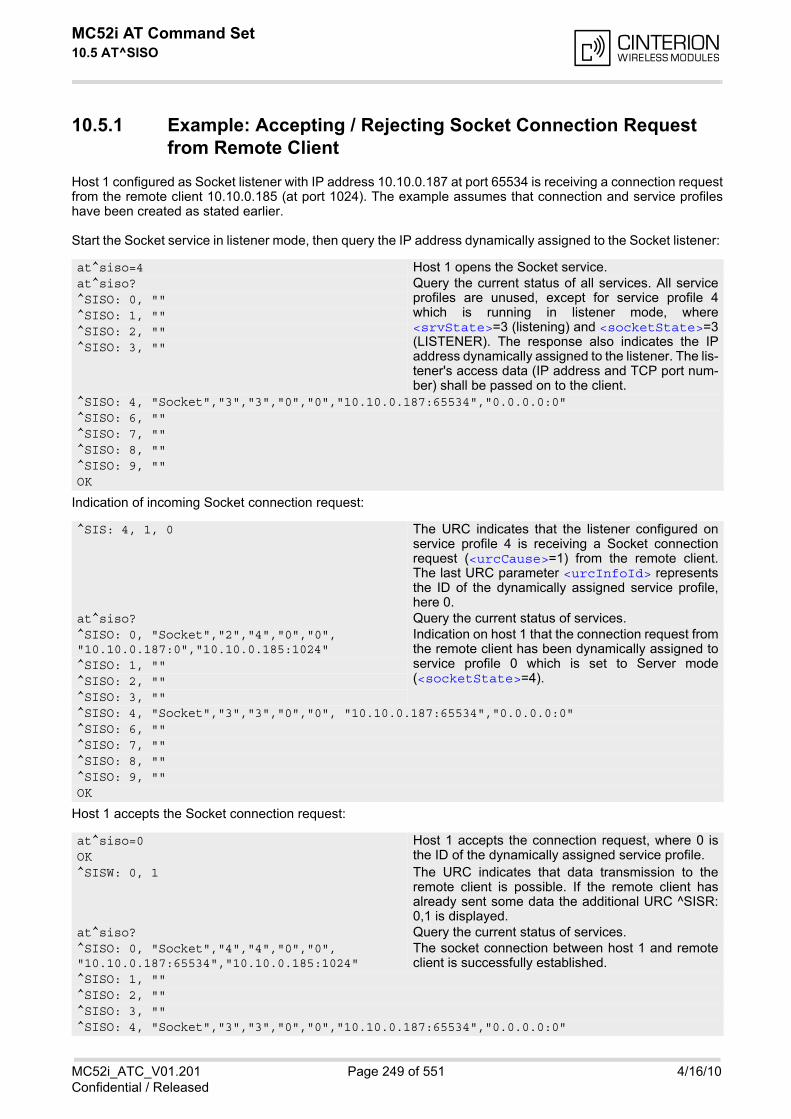
MC52i AT Command Set 10.5 AT^SISO
MC52i_ATC_V01.201 Page 249 of 551 4/16/10Confidential / Released
10.5.1 Example: Accepting / Rejecting Socket Connection Request from Remote Client
Host 1 configured as Socket listener with IP address 10.10.0.187 at port 65534 is receiving a connection requestfrom the remote client 10.10.0.185 (at port 1024). The example assumes that connection and service profileshave been created as stated earlier.
Start the Socket service in listener mode, then query the IP address dynamically assigned to the Socket listener:
Indication of incoming Socket connection request:
Host 1 accepts the Socket connection request:
at^siso=4 Host 1 opens the Socket service.at^siso? Query the current status of all services. All service
profiles are unused, except for service profile 4which is running in listener mode, where<srvState>=3 (listening) and <socketState>=3(LISTENER). The response also indicates the IPaddress dynamically assigned to the listener. The lis-tener's access data (IP address and TCP port num-ber) shall be passed on to the client.
^SISO: 0, ""^SISO: 1, ""^SISO: 2, ""^SISO: 3, ""
^SISO: 4, "Socket","3","3","0","0","10.10.0.187:65534","0.0.0.0:0"^SISO: 6, ""^SISO: 7, ""^SISO: 8, ""^SISO: 9, ""OK
^SIS: 4, 1, 0 The URC indicates that the listener configured onservice profile 4 is receiving a Socket connectionrequest (<urcCause>=1) from the remote client.The last URC parameter <urcInfoId> representsthe ID of the dynamically assigned service profile,here 0.
at^siso? Query the current status of services.^SISO: 0, "Socket","2","4","0","0", "10.10.0.187:0","10.10.0.185:1024"
Indication on host 1 that the connection request fromthe remote client has been dynamically assigned toservice profile 0 which is set to Server mode(<socketState>=4).
^SISO: 1, ""^SISO: 2, ""^SISO: 3, ""^SISO: 4, "Socket","3","3","0","0", "10.10.0.187:65534","0.0.0.0:0"^SISO: 6, ""^SISO: 7, ""^SISO: 8, ""^SISO: 9, ""OK
at^siso=0 Host 1 accepts the connection request, where 0 isthe ID of the dynamically assigned service profile.OK
^SISW: 0, 1 The URC indicates that data transmission to theremote client is possible. If the remote client hasalready sent some data the additional URC ^SISR:0,1 is displayed.
at^siso? Query the current status of services.^SISO: 0, "Socket","4","4","0","0", "10.10.0.187:65534","10.10.0.185:1024"
The socket connection between host 1 and remoteclient is successfully established.
^SISO: 1, ""^SISO: 2, ""^SISO: 3, ""^SISO: 4, "Socket","3","3","0","0","10.10.0.187:65534","0.0.0.0:0"

MC52i AT Command Set 10.5 AT^SISO
MC52i_ATC_V01.201 Page 250 of 551 4/16/10Confidential / Released
Host 1 rejects the Socket connection request:
^SISO: 6, ""^SISO: 7, ""^SISO: 8, ""^SISO: 9, ""OK
at^sisc=0 Host 1 rejects the connection request, where 0 is theID of the dynamically assigned service profile.OK
at^siso? Query the current status of services.^SISO: 0, "" The dynamically assigned service profile is free
again. The Socket listener stays at <srvState>=3(listening) and <socketState>=3 (LISTENER).
^SISO: 1, ""^SISO: 2, ""^SISO: 3, ""^SISO: 4, "Socket","3","3","0","0","10.10.0.187:65534","0.0.0.0:0"^SISO: 6, ""^SISO: 7, ""^SISO: 8, ""^SISO: 9, ""OK
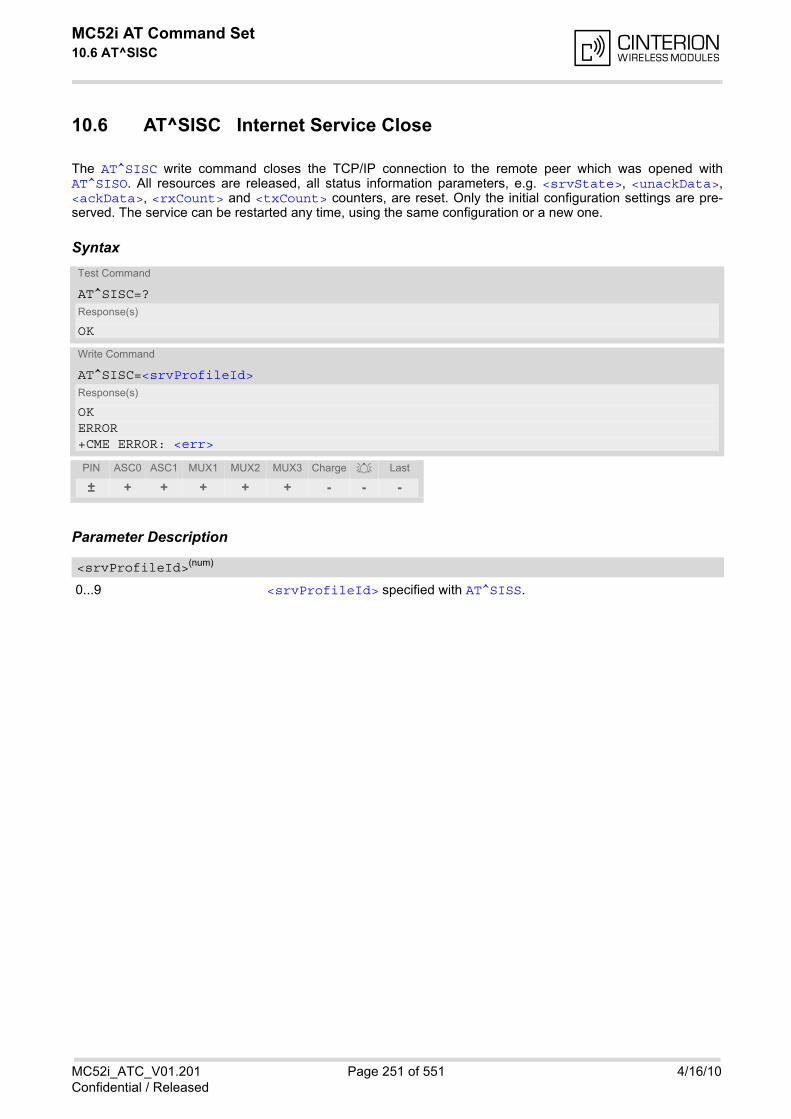
MC52i AT Command Set 10.6 AT^SISC
MC52i_ATC_V01.201 Page 251 of 551 4/16/10Confidential / Released
10.6 AT^SISC Internet Service Close
The AT^SISC write command closes the TCP/IP connection to the remote peer which was opened withAT^SISO. All resources are released, all status information parameters, e.g. <srvState>, <unackData>,<ackData>, <rxCount> and <txCount> counters, are reset. Only the initial configuration settings are pre-served. The service can be restarted any time, using the same configuration or a new one.
Syntax
Parameter Description
0...9 <srvProfileId> specified with AT^SISS.
Test Command
AT^SISC=?Response(s)
OK
Write Command
AT^SISC=<srvProfileId>Response(s)
OK ERROR +CME ERROR: <err>
PIN ASC0 ASC1 MUX1 MUX2 MUX3 Charge Last
± + + + + + - - -
<srvProfileId>(num)
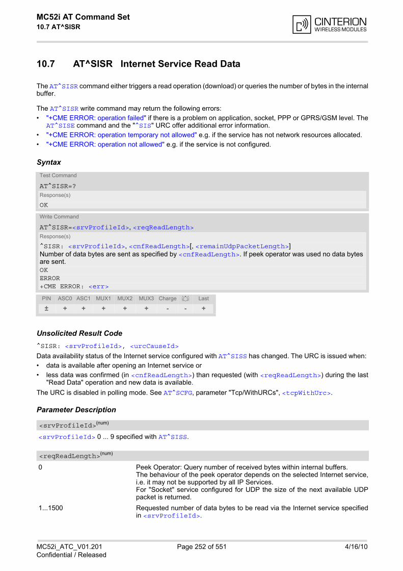
MC52i AT Command Set 10.7 AT^SISR
MC52i_ATC_V01.201 Page 252 of 551 4/16/10Confidential / Released
10.7 AT^SISR Internet Service Read Data
The AT^SISR command either triggers a read operation (download) or queries the number of bytes in the internalbuffer.
The AT^SISR write command may return the following errors:
• "+CME ERROR: operation failed" if there is a problem on application, socket, PPP or GPRS/GSM level. TheAT^SISE command and the "^SIS" URC offer additional error information.
• "+CME ERROR: operation temporary not allowed" e.g. if the service has not network resources allocated.
• "+CME ERROR: operation not allowed" e.g. if the service is not configured.
Syntax
Unsolicited Result Code^SISR: <srvProfileId>, <urcCauseId>
Data availability status of the Internet service configured with AT^SISS has changed. The URC is issued when:
• data is available after opening an Internet service or
• less data was confirmed (in <cnfReadLength>) than requested (with <reqReadLength>) during the last"Read Data" operation and new data is available.
The URC is disabled in polling mode. See AT^SCFG, parameter "Tcp/WithURCs", <tcpWithUrc>.
Parameter Description
<srvProfileId> 0 ... 9 specified with AT^SISS.
0 Peek Operator: Query number of received bytes within internal buffers. The behaviour of the peek operator depends on the selected Internet service,i.e. it may not be supported by all IP Services. For "Socket" service configured for UDP the size of the next available UDPpacket is returned.
1...1500 Requested number of data bytes to be read via the Internet service specifiedin <srvProfileId>.
Test Command
AT^SISR=?Response(s)
OK
Write Command
AT^SISR=<srvProfileId>, <reqReadLength>Response(s)
^SISR: <srvProfileId>, <cnfReadLength>[, <remainUdpPacketLength>]Number of data bytes are sent as specified by <cnfReadLength>. If peek operator was used no data bytes are sent. OKERROR+CME ERROR: <err>
PIN ASC0 ASC1 MUX1 MUX2 MUX3 Charge Last
± + + + + + - - +
<srvProfileId>(num)
<reqReadLength>(num)

MC52i AT Command Set 10.7 AT^SISR
MC52i_ATC_V01.201 Page 253 of 551 4/16/10Confidential / Released
-2 Indicates end of data. Data transfer has been finished (all data have been read)and the service can be closed with AT^SISC.
-1 Applies only to HTTP: Querying number of available bytes is not supported bythe HTTP service.
0 Indicates that no further data is available at the moment.
>0 Number of available data bytes. The range is determined by<reqReadLength>:If <reqReadLength> was greater than 0, then <cnfReadLength> may beless or equal to the value requested with <reqReadLength>. If <reqReadLength> equals 0 (peek operator) the value indicated by<cnfReadLength> may be greater than 1500.
Indicates whether or not data is available for reading with AT^SISR.
1 Data is available and can be read by sending the AT^SISR command. TheURC appears when less data was confirmed (in <cnfReadLength>) thanrequested (with <reqReadLength>) during the last "Read Data" operationand new data is available.
2 End of data. Data transfer has completed (all data read). The service can beclosed with AT^SISC.
Optional third parameter of the AT^SISR write command response displayed only if the Socket service uses theUDP protocol. The reception of each datagram must be completed before the next datagram can be received. This may be aproblem if the buffer of the host application is limited and not designed to handle the maximum packet size of1500 bytes. To compensate this, the host is advised to request, via <reqReadLength>, an amount less orequal its maxmimum buffer capacity and wait for the resulting AT^SISR write command response with param-eter <remainUdpPacketLength>. The benefit of this approach is that the host may properly receive all partsof a UDP datagram, as after each received data part the number of remaining bytes is synchronized, until read-ing the datagram is finished.If the currently read datagram is smaller than the number of bytes requested by the host the <remainUdpPack-etLength> parameter is omitted. Further write attempts with AT^SISR are denied as long as the <remainUdpPacketLength> is unequal 0 oris not omitted. In this case the service returns "+CME ERROR: operation of service temporary not allowed".
0 Indicates that all bytes of the current UDP datagram are read.
1...(max. data size)-1 Indicates that the currently read UDP datagram is not yet complete. The dis-played value is the remaining number of bytes. <remainUdpPacketLength> is unequal 0 until reading all parts of the cur-rent datagram is finished.
10.7.1 Example: Socket Host Reads Small Amounts of UDP Data Pack-ets (URC Mode)
This section applies only to the Socket service using the UDP protocol. The example shows how to read UDPpackets if the buffer of the host application can handle only a few bytes. There are two datagrams available forreading. Buffer size: 6 bytesDatagram A = 18 bytes (content "THIS_IS_DATAGRAM_A")Datagram B = 3 bytes (content "NEW")
<cnfReadLength>(num)
<urcCauseId>(num)
<remainUdpPacketLength>(num)
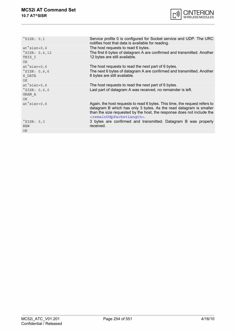
MC52i AT Command Set 10.7 AT^SISR
MC52i_ATC_V01.201 Page 254 of 551 4/16/10Confidential / Released
^SISR: 0,1 Service profile 0 is configured for Socket service and UDP. The URCnotifies host that data is available for reading.
at^sisr=0,6 The host requests to read 6 bytes.^SISR: 0,6,12THIS_I
The first 6 bytes of datagram A are confirmed and transmitted. Another12 bytes are still available.
OKat^sisr=0,6 The host requests to read the next part of 6 bytes.^SISR: 0,6,6S_DATA
The next 6 bytes of datagram A are confirmed and transmitted. Another6 bytes are still available.
OKat^sisr=0,6 The host requests to read the next part of 6 bytes.^SISR: 0,6,0GRAM_A
Last part of datagram A was received, no remainder is left.
OKat^sisr=0,6 Again, the host requests to read 6 bytes. This time, the request refers to
datagram B which has only 3 bytes. As the read datagram is smallerthan the size requested by the host, the response does not include the<remainUdpPacketLength>.
^SISR: 0,3NEW
3 bytes are confirmed and transmitted. Datagram B was properlyreceived.
OK
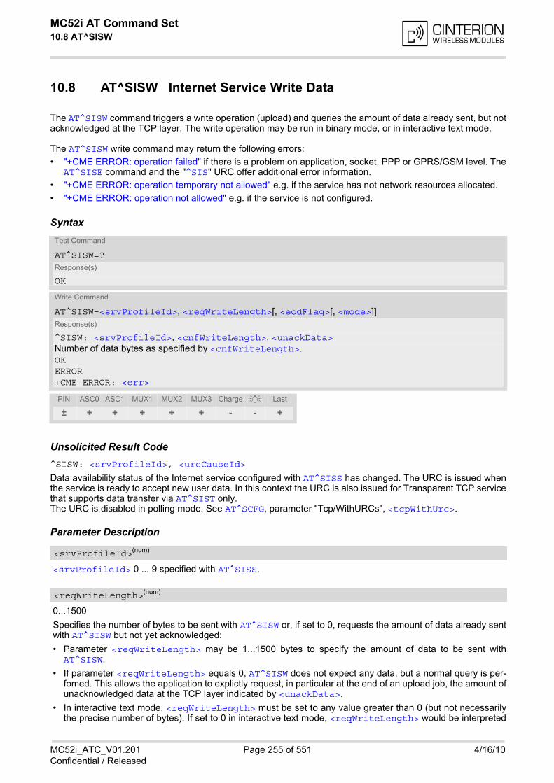
MC52i AT Command Set 10.8 AT^SISW
MC52i_ATC_V01.201 Page 255 of 551 4/16/10Confidential / Released
10.8 AT^SISW Internet Service Write Data
The AT^SISW command triggers a write operation (upload) and queries the amount of data already sent, but notacknowledged at the TCP layer. The write operation may be run in binary mode, or in interactive text mode.
The AT^SISW write command may return the following errors:
• "+CME ERROR: operation failed" if there is a problem on application, socket, PPP or GPRS/GSM level. TheAT^SISE command and the "^SIS" URC offer additional error information.
• "+CME ERROR: operation temporary not allowed" e.g. if the service has not network resources allocated.
• "+CME ERROR: operation not allowed" e.g. if the service is not configured.
Syntax
Unsolicited Result Code^SISW: <srvProfileId>, <urcCauseId>
Data availability status of the Internet service configured with AT^SISS has changed. The URC is issued whenthe service is ready to accept new user data. In this context the URC is also issued for Transparent TCP servicethat supports data transfer via AT^SIST only. The URC is disabled in polling mode. See AT^SCFG, parameter "Tcp/WithURCs", <tcpWithUrc>.
Parameter Description
<srvProfileId> 0 ... 9 specified with AT^SISS.
0...1500
Specifies the number of bytes to be sent with AT^SISW or, if set to 0, requests the amount of data already sentwith AT^SISW but not yet acknowledged:
• Parameter <reqWriteLength> may be 1...1500 bytes to specify the amount of data to be sent withAT^SISW.
• If parameter <reqWriteLength> equals 0, AT^SISW does not expect any data, but a normal query is per-fomed. This allows the application to explictly request, in particular at the end of an upload job, the amount ofunacknowledged data at the TCP layer indicated by <unackData>.
• In interactive text mode, <reqWriteLength> must be set to any value greater than 0 (but not necessarilythe precise number of bytes). If set to 0 in interactive text mode, <reqWriteLength> would be interpreted
Test Command
AT^SISW=?Response(s)
OK
Write Command
AT^SISW=<srvProfileId>, <reqWriteLength>[, <eodFlag>[, <mode>]]Response(s)
^SISW: <srvProfileId>, <cnfWriteLength>, <unackData>Number of data bytes as specified by <cnfWriteLength>. OKERROR+CME ERROR: <err>
PIN ASC0 ASC1 MUX1 MUX2 MUX3 Charge Last
± + + + + + - - +
<srvProfileId>(num)
<reqWriteLength>(num)
MC52i AT Command Set 10.8 AT^SISW
MC52i_ATC_V01.201 Page 256 of 551 4/16/10Confidential / Released
as query for unacknowledged data and, thus, prevent data transfer.
• If Socket service is selected with UDP protocol
- <reqWriteLength>=0 can be used to send an empty UDP packet;
- it is recommended that the size of each data packet be limited to 1460 bytes. Otherwise, it is possible thatthe following URC occurs: "^SIS: <id>, 0, 9, The supplied buffer was too small / large".
End of data indication flag.Parameter is ignored for HTTP, POP3, FTP download.
[0] No end of data. Other data may follow to be transmitted via the Internet service.
1 End of data is signalled to the Internet Service. Further AT^SISW write com-mands return an error response. However, reading data may be possible. The<eodFlag> is effective only if the <reqWriteLength> equals <cnfWrite-Length>, in particular if the <reqWriteLength> equals 0.If <mode> equals 1 the <eodFlag> is effective only if the write operation hasbeen finished with CTRL-Z.
Control how the application provides the data bytes to be sent.
[0] Binary mode This mode allows sending a number of bytes defined with parameter<reqWriteLength>.
1 Interactive text mode This mode allows the user to type and send 8-bit ASCII characters while theservice is open. Ctrl-Z terminates data input and causes the data to be trans-ferred.Interactive text mode requires that the <reqWriteLength> is set to any valuegreater than 0 (though it is not necessary to specify the precise number ofbytes). In this case the <cnfWriteLength> parameter indicates the maxi-mum length of the data stream without control character CTRL-Z. In interactive text mode, the following characters are predefined as controlcodes:
• BACKSPACE ("\x08") deletes the last given character,
• CTRL-Z ("\x1a") terminates the input,
• ESC ("\x1b") aborts the command. An <eodFlag> is ignored in this case.
The V.25 command ATE also controls the echo mode of the interactive textmode. If echo is enabled (ATE1) all characters are echoed until <cnfWrite-Length> is reached. Any attempt to input further data ends up with the warn-ing message 4001 indicated after the data stream has been completed withCTRL-Z, nevertheless all data within the range of <cnfWriteLength> will besent. See also Section 10.11, Internet Service URC "^SIS". ATE0 disables theecho mode generally.
0...1500 Confirmed number of data bytes which can be transmitted via the Internet ser-vice configured in <srvProfileId>. In binary mode (see <mode>) this num-ber may be less or equal to the value requested with <reqWriteLength>.The application has to deliver exactly the number of bytes indicated by <cnf-WriteLength>. A 0 value means that no data can be written at this time, i.e.it serves as a flow control mechanism. In interactive text mode, <cnfWriteLength> indicates the maximum numberof bytes it can process. Characters above the indicated number are ignored.
<eodFlag>(num)
<mode>(num)
<cnfWriteLength>(num)
MC52i AT Command Set 10.8 AT^SISW
MC52i_ATC_V01.201 Page 257 of 551 4/16/10Confidential / Released
Number of data bytes already sent but not yet acknowledged at the TCP layer. The value is constantly changing until the entire upload job has completed. If the value equals 0 all data sent sofar is acknowledged. In binary mode, <unackData> includes the <cnfWriteLength> value of the pending write operation. There-fore, the very first write operation of an upload job returns identical values for <cnfWriteLength> and<unackData>. This mechanism allows the host application to easily verify whether or not the remote host has successfullyreceived the data. Parameter is not applicable to HTTP, POP3, SMTP and Socket with UDP protocol. For these services thecounter is always set to 0.
1 The service is ready to accept new user data.
2 Data transfer has been finished successfully and Internet service may beclosed without loss of data.
Notes• The AT^SISW write command must be terminated only with the ASCII character set with ATS3. The factory
default for S3 is #13 (Carriage Return). Do not send any further characters after the S3 end-of-line identifier,until the response "^SISW" is received. This is necessary to avoid that any characters related to the AT com-mand can be interpreted as being part of the data stream to be transferred. Also refer to Section 1.4, AT Com-mand Syntax.
• If the Socket service is configured for use as UDP client and fixed size and the interactive text mode is active,the PDU length always equals the specified fixed length. If the input characters exceed the specified fixedlength, then all surplus characters will be ignored. If the input characters are less than the specified fixedlength, then the remaining range will be filled with "\0" bytes.
10.8.1 Usage of parameter <eodFlag>
<unackData>(num)
<urcCauseId>(num)
Service type
Socket After the service accepts the end-of-data flag the service state changes to "Closing". No fur-ther user data is accepted. After releasing the TCP link the service remains in state "Down".
FTP Parameter only applicable for FTP upload session. After accepting the end-of-data flag the service state changes to "Closing" and starts to end the running FTP session. No further user data is accepted. After the FTP session is completed on FTP protocol level the service state switches to "Down". In case of successful completion the URC "^SISW: x,2" is generated.
SMTP SMTP service sends some "closing" commands to the SMTP server which are necessary to mark the email as successfully sent on the server. The service enters "Closing" state and remains in it until the final protocol exchange with the SMTP server has been completed. The "OK" response following AT^SISW indicates that the SMTP service has accepted the last data - IT DOES NOT indicate the successful completion of the SMTP service. Successful completion will be indicated either by the appropriate URC "^SISW:x,2" or due to the fact that the SMTP service state changes to "Down" state without any error.
HTTP / POP3 Parameter not applicable, i.e. value is ignored.

MC52i AT Command Set 10.9 AT^SIST
MC52i_ATC_V01.201 Page 258 of 551 4/16/10Confidential / Released
10.9 AT^SIST Enter Transparent Access Mode
The AT^SIST command applies only to the Transparent service defined with AT^SISS. It can be used after theTransparent service has been opened with AT^SISO and is in "Up" state (<srvState>=4). If the service is not"Up" trying to open it will be denied with "+CME ERROR: operation temporary not allowed".
There are two ways to verify that the service is "Up": Each time after opening the service with AT^SISO wait forthe "^SISW: x, 1" URC (if URC mode is enabled). In addition, or when using Polling mode, you can request the<srvState> with AT^SISO or AT^SISI.
Then, after entering the AT^SIST command, the CONNECT response notifies that the service has entered trans-parent access mode and is ready to transparently send and receive payload data over the serial interface. In thismode, the signaling of URCs is dependent on the settings made with AT^SCFG, parameter <udri>.
There are several ways to quit the transparent access mode and revert to AT command mode:
• +++ escape sequence (also transmitted over the air)
• DTR ON-OFF transition (see AT&D for configuring DTR line)
• "etx" parameter set within the server address for transparent access mode (see AT^SISS, <srvParmTag>"address".
Switching back and forth between both modes does not affect the underlying socket and has no influence on theservice <srvState>.
The Transparent service remains in <srvState> 4 ("Up") until closed with AT^SISC or released by the server.
If the Transparent service is released by the server the following applies:
• If the service is in transparent access mode (CONNECT mode): ME returns to AT command mode, issues aspecific "NO CARRIER" result code and goes to <srvState> 6 ("Down"). The "NO CARRIER" result codestarts with 0x10 (DLE) and 0x04 (EOT) and ends with the characters defined by ATS3 and ATS4.
• If the service is in AT command mode and no data is pending: "^SIS" URCs notify the client that the serverhas disconnected and the ME goes to <srvState> 6 ("Down").
• If the service is in AT command mode and data is still available: "^SIS" URCs notify the client that the serverhas disconnected and the service remains in <srvState> 5 ("Closing"). In this case the client shall open thetransparent access mode with AT^SIST. After the CONNECT response, all remaining data can be trans-ferred.
• In all above scenarios, the Transparent service shall be closed with AT^SISC after it has gone to<srvState> 6 ("Down"). Trying to return to transparent access mode with AT^SIST would only end up with"NO CARRIER" once again and is not recommended.
• Use AT^SISO and AT^SISI to check the <srvState>.
• Please note that the "^SIS" URCs mentioned above vary with the network. There may be for example "^SIS"URCs with <urcInfoId> 15 ("Remote host has reset the connection") and 19 ("Socket has been shutdown). See Section 10.11, Internet Service URC "^SIS" for a list of possible URCs.
SyntaxTest Command
AT^SIST=?Response(s)
OK
Write Command
AT^SIST=<srvProfileId>Response(s)
CONNECT(indicates that ME has entered transparent access mode)OK
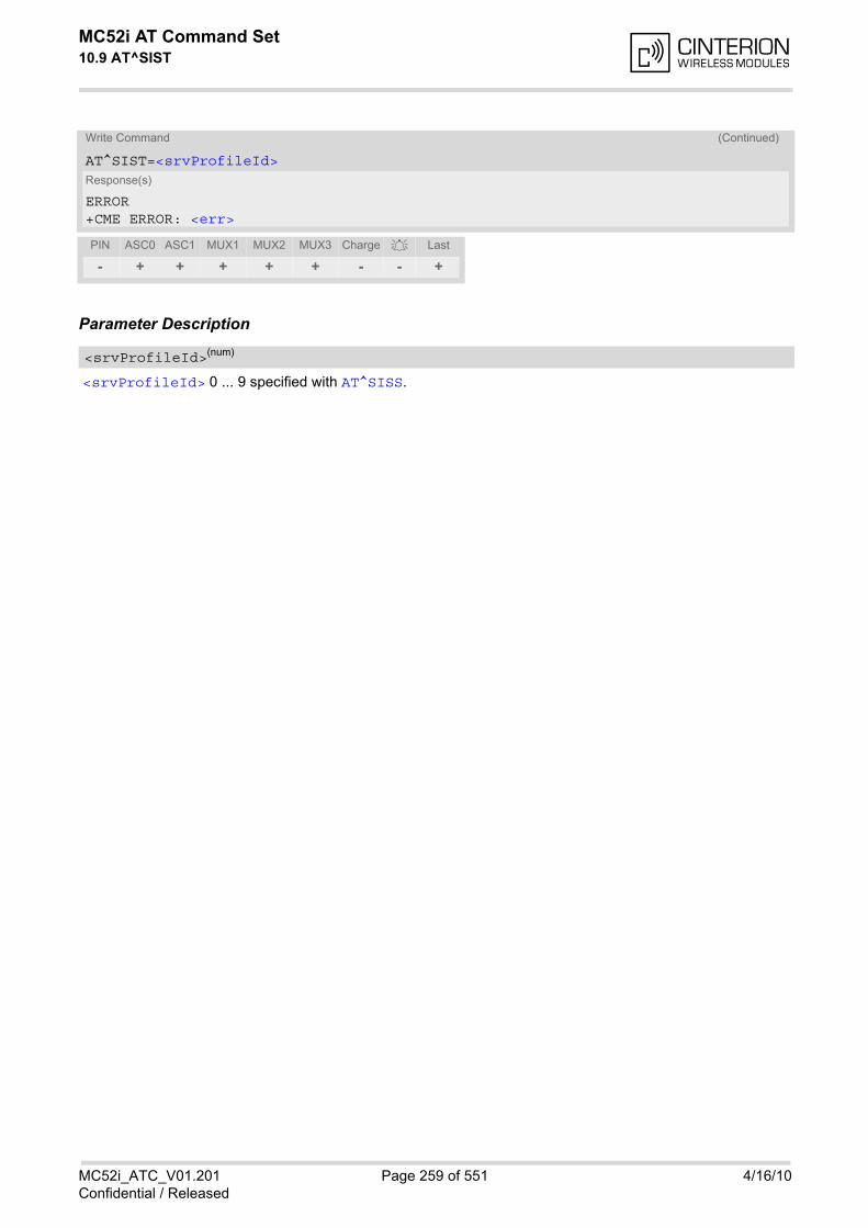
MC52i AT Command Set 10.9 AT^SIST
MC52i_ATC_V01.201 Page 259 of 551 4/16/10Confidential / Released
Parameter Description
<srvProfileId> 0 ... 9 specified with AT^SISS.
ERROR+CME ERROR: <err>
PIN ASC0 ASC1 MUX1 MUX2 MUX3 Charge Last
- + + + + + - - +
<srvProfileId>(num)
Write Command (Continued)
AT^SIST=<srvProfileId>Response(s)
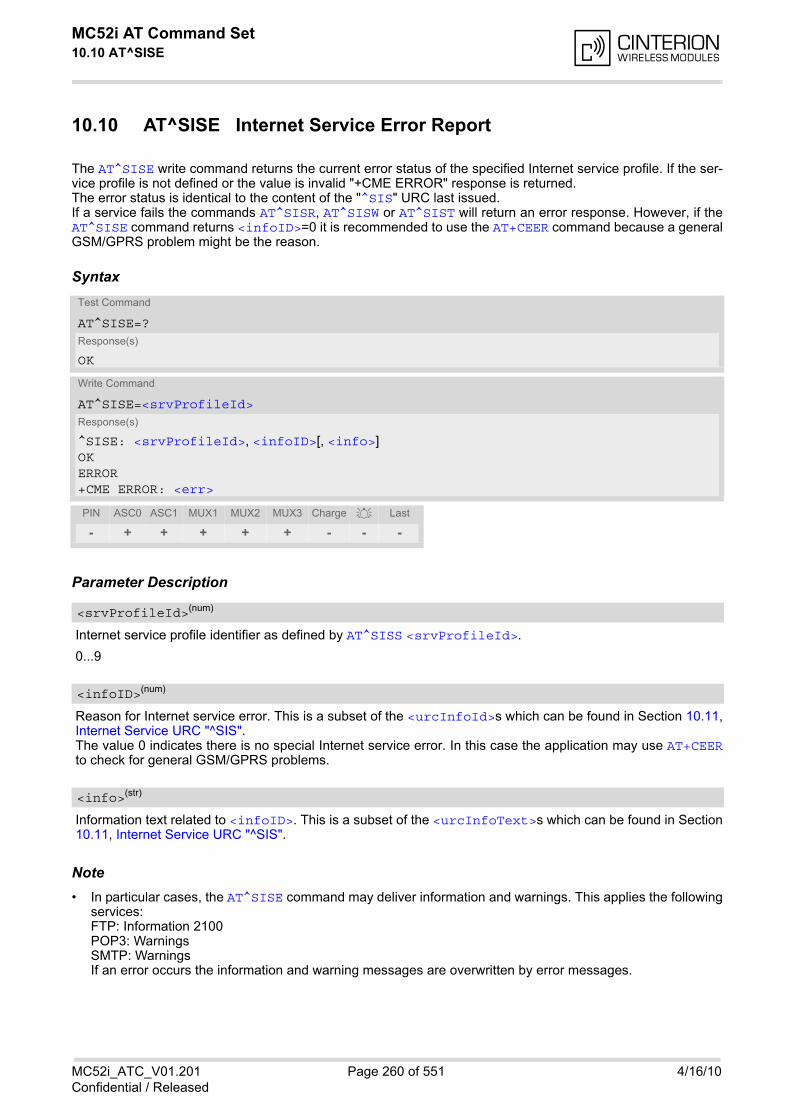
MC52i AT Command Set 10.10 AT^SISE
MC52i_ATC_V01.201 Page 260 of 551 4/16/10Confidential / Released
10.10 AT^SISE Internet Service Error Report
The AT^SISE write command returns the current error status of the specified Internet service profile. If the ser-vice profile is not defined or the value is invalid "+CME ERROR" response is returned. The error status is identical to the content of the "^SIS" URC last issued. If a service fails the commands AT^SISR, AT^SISW or AT^SIST will return an error response. However, if theAT^SISE command returns <infoID>=0 it is recommended to use the AT+CEER command because a generalGSM/GPRS problem might be the reason.
Syntax
Parameter Description
Internet service profile identifier as defined by AT^SISS <srvProfileId>.
0...9
Reason for Internet service error. This is a subset of the <urcInfoId>s which can be found in Section 10.11,Internet Service URC "^SIS". The value 0 indicates there is no special Internet service error. In this case the application may use AT+CEERto check for general GSM/GPRS problems.
Information text related to <infoID>. This is a subset of the <urcInfoText>s which can be found in Section10.11, Internet Service URC "^SIS".
Note• In particular cases, the AT^SISE command may deliver information and warnings. This applies the following
services:FTP: Information 2100POP3: WarningsSMTP: WarningsIf an error occurs the information and warning messages are overwritten by error messages.
Test Command
AT^SISE=?Response(s)
OK
Write Command
AT^SISE=<srvProfileId>Response(s)
^SISE: <srvProfileId>, <infoID>[, <info>]OKERROR+CME ERROR: <err>
PIN ASC0 ASC1 MUX1 MUX2 MUX3 Charge Last
- + + + + + - - -
<srvProfileId>(num)
<infoID>(num)
<info>(str)
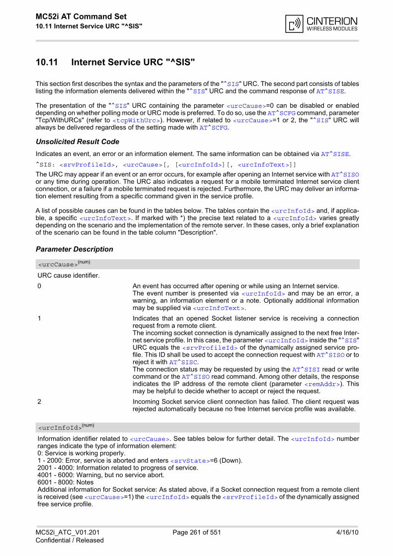
MC52i AT Command Set 10.11 Internet Service URC "^SIS"
MC52i_ATC_V01.201 Page 261 of 551 4/16/10Confidential / Released
10.11 Internet Service URC "^SIS"
This section first describes the syntax and the parameters of the "^SIS" URC. The second part consists of tableslisting the information elements delivered within the "^SIS" URC and the command response of AT^SISE.
The presentation of the "^SIS" URC containing the parameter <urcCause>=0 can be disabled or enableddepending on whether polling mode or URC mode is preferred. To do so, use the AT^SCFG command, parameter"Tcp/WithURCs" (refer to <tcpWithUrc>). However, if related to <urcCause>=1 or 2, the "^SIS" URC willalways be delivered regardless of the setting made with AT^SCFG.
Unsolicited Result CodeIndicates an event, an error or an information element. The same information can be obtained via AT^SISE.
^SIS: <srvProfileId>, <urcCause>[, [<urcInfoId>][, <urcInfoText>]]
The URC may appear if an event or an error occurs, for example after opening an Internet service with AT^SISOor any time during operation. The URC also indicates a request for a mobile terminated Internet service clientconnection, or a failure if a mobile terminated request is rejected. Furthermore, the URC may deliver an informa-tion element resulting from a specific command given in the service profile.
A list of possible causes can be found in the tables below. The tables contain the <urcInfoId> and, if applica-ble, a specific <urcInfoText>. If marked with *) the precise text related to a <urcInfoId> varies greatlydepending on the scenario and the implementation of the remote server. In these cases, only a brief explanationof the scenario can be found in the table column "Description".
Parameter Description
URC cause identifier.
0 An event has occurred after opening or while using an Internet service. The event number is presented via <urcInfoId> and may be an error, awarning, an information element or a note. Optionally additional informationmay be supplied via <urcInfoText>.
1 Indicates that an opened Socket listener service is receiving a connectionrequest from a remote client. The incoming socket connection is dynamically assigned to the next free Inter-net service profile. In this case, the parameter <urcInfoId> inside the "^SIS"URC equals the <srvProfileId> of the dynamically assigned service pro-file. This ID shall be used to accept the connection request with AT^SISO or toreject it with AT^SISC. The connection status may be requested by using the AT^SISI read or writecommand or the AT^SISO read command. Among other details, the responseindicates the IP address of the remote client (parameter <remAddr>). Thismay be helpful to decide whether to accept or reject the request.
2 Incoming Socket service client connection has failed. The client request wasrejected automatically because no free Internet service profile was available.
Information identifier related to <urcCause>. See tables below for further detail. The <urcInfoId> numberranges indicate the type of information element:0: Service is working properly.1 - 2000: Error, service is aborted and enters <srvState>=6 (Down).2001 - 4000: Information related to progress of service.4001 - 6000: Warning, but no service abort.6001 - 8000: NotesAdditional information for Socket service: As stated above, if a Socket connection request from a remote clientis received (see <urcCause>=1) the <urcInfoId> equals the <srvProfileId> of the dynamically assignedfree service profile.
<urcCause>(num)
<urcInfoId>(num)
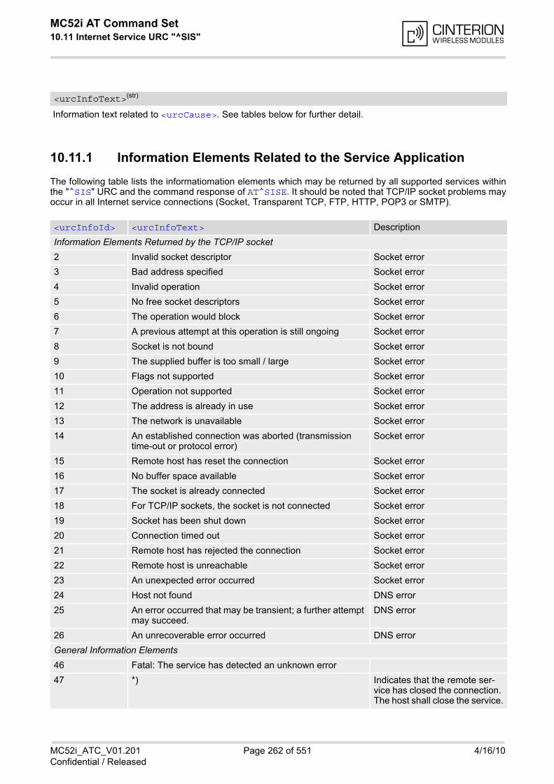
MC52i AT Command Set 10.11 Internet Service URC "^SIS"
MC52i_ATC_V01.201 Page 262 of 551 4/16/10Confidential / Released
Information text related to <urcCause>. See tables below for further detail.
10.11.1 Information Elements Related to the Service Application
The following table lists the informatiomation elements which may be returned by all supported services withinthe "^SIS" URC and the command response of AT^SISE. It should be noted that TCP/IP socket problems mayoccur in all Internet service connections (Socket, Transparent TCP, FTP, HTTP, POP3 or SMTP).
<urcInfoText>(str)
<urcInfoId> <urcInfoText> Description
Information Elements Returned by the TCP/IP socket
2 Invalid socket descriptor Socket error
3 Bad address specified Socket error
4 Invalid operation Socket error
5 No free socket descriptors Socket error
6 The operation would block Socket error
7 A previous attempt at this operation is still ongoing Socket error
8 Socket is not bound Socket error
9 The supplied buffer is too small / large Socket error
10 Flags not supported Socket error
11 Operation not supported Socket error
12 The address is already in use Socket error
13 The network is unavailable Socket error
14 An established connection was aborted (transmission time-out or protocol error)
Socket error
15 Remote host has reset the connection Socket error
16 No buffer space available Socket error
17 The socket is already connected Socket error
18 For TCP/IP sockets, the socket is not connected Socket error
19 Socket has been shut down Socket error
20 Connection timed out Socket error
21 Remote host has rejected the connection Socket error
22 Remote host is unreachable Socket error
23 An unexpected error occurred Socket error
24 Host not found DNS error
25 An error occurred that may be transient; a further attempt may succeed.
DNS error
26 An unrecoverable error occurred DNS error
General Information Elements
46 Fatal: The service has detected an unknown error
47 *) Indicates that the remote ser-vice has closed the connection. The host shall close the service.
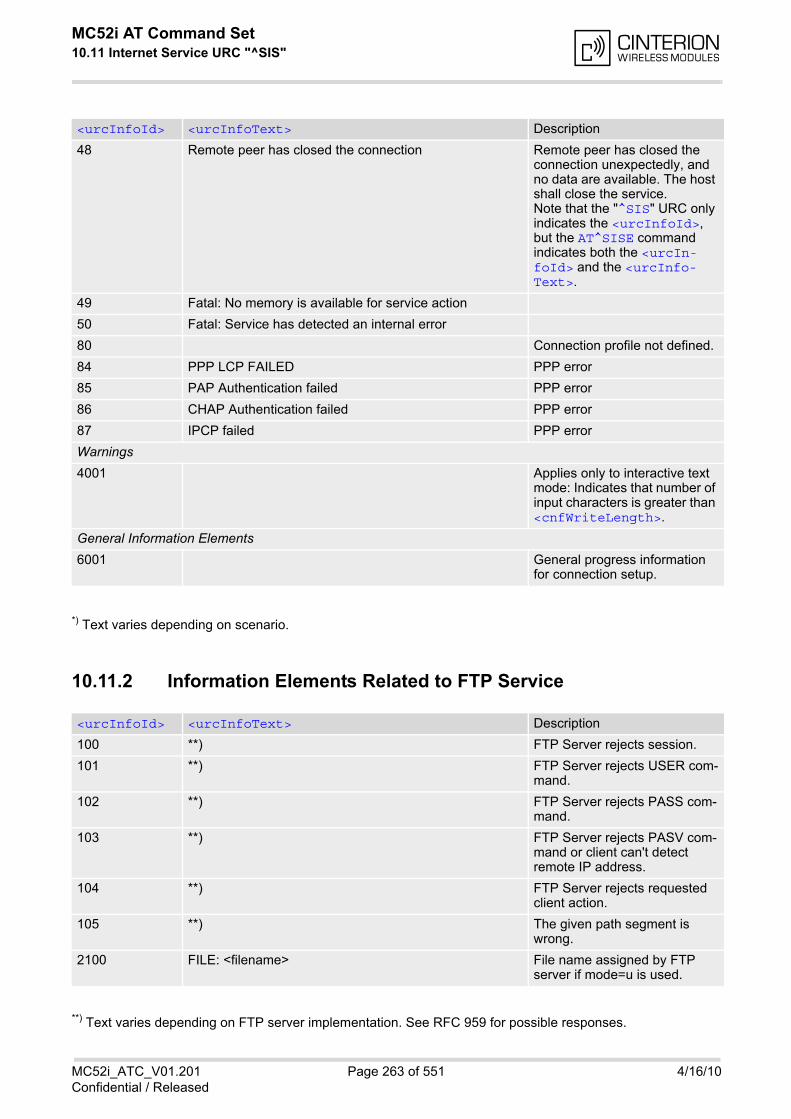
MC52i AT Command Set 10.11 Internet Service URC "^SIS"
MC52i_ATC_V01.201 Page 263 of 551 4/16/10Confidential / Released
*) Text varies depending on scenario.
10.11.2 Information Elements Related to FTP Service
**) Text varies depending on FTP server implementation. See RFC 959 for possible responses.
48 Remote peer has closed the connection Remote peer has closed the connection unexpectedly, and no data are available. The host shall close the service.Note that the "^SIS" URC only indicates the <urcInfoId>, but the AT^SISE command indicates both the <urcIn-foId> and the <urcInfo-Text>.
49 Fatal: No memory is available for service action
50 Fatal: Service has detected an internal error
80 Connection profile not defined.
84 PPP LCP FAILED PPP error
85 PAP Authentication failed PPP error
86 CHAP Authentication failed PPP error
87 IPCP failed PPP error
Warnings
4001 Applies only to interactive text mode: Indicates that number of input characters is greater than <cnfWriteLength>.
General Information Elements
6001 General progress information for connection setup.
<urcInfoId> <urcInfoText> Description
100 **) FTP Server rejects session.
101 **) FTP Server rejects USER com-mand.
102 **) FTP Server rejects PASS com-mand.
103 **) FTP Server rejects PASV com-mand or client can't detect remote IP address.
104 **) FTP Server rejects requested client action.
105 **) The given path segment is wrong.
2100 FILE: <filename> File name assigned by FTP server if mode=u is used.
<urcInfoId> <urcInfoText> Description
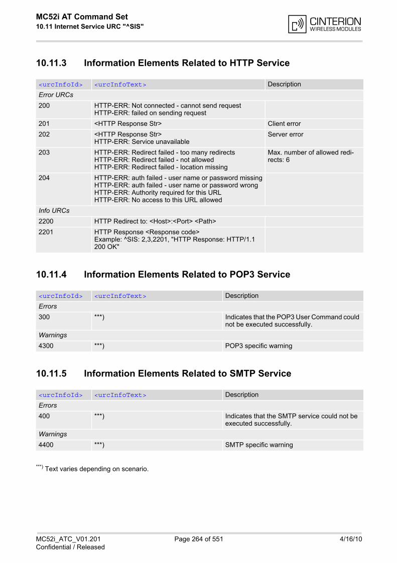
MC52i AT Command Set 10.11 Internet Service URC "^SIS"
MC52i_ATC_V01.201 Page 264 of 551 4/16/10Confidential / Released
10.11.3 Information Elements Related to HTTP Service
10.11.4 Information Elements Related to POP3 Service
10.11.5 Information Elements Related to SMTP Service
***) Text varies depending on scenario.
<urcInfoId> <urcInfoText> Description
Error URCs
200 HTTP-ERR: Not connected - cannot send requestHTTP-ERR: failed on sending request
201 <HTTP Response Str> Client error
202 <HTTP Response Str> HTTP-ERR: Service unavailable
Server error
203 HTTP-ERR: Redirect failed - too many redirectsHTTP-ERR: Redirect failed - not allowedHTTP-ERR: Redirect failed - location missing
Max. number of allowed redi-rects: 6
204 HTTP-ERR: auth failed - user name or password missingHTTP-ERR: auth failed - user name or password wrongHTTP-ERR: Authority required for this URLHTTP-ERR: No access to this URL allowed
Info URCs
2200 HTTP Redirect to: <Host>:<Port> <Path>
2201 HTTP Response <Response code>Example: ^SIS: 2,3,2201, "HTTP Response: HTTP/1.1 200 OK"
<urcInfoId> <urcInfoText> Description
Errors
300 ***) Indicates that the POP3 User Command could not be executed successfully.
Warnings
4300 ***) POP3 specific warning
<urcInfoId> <urcInfoText> Description
Errors
400 ***) Indicates that the SMTP service could not be executed successfully.
Warnings
4400 ***) SMTP specific warning
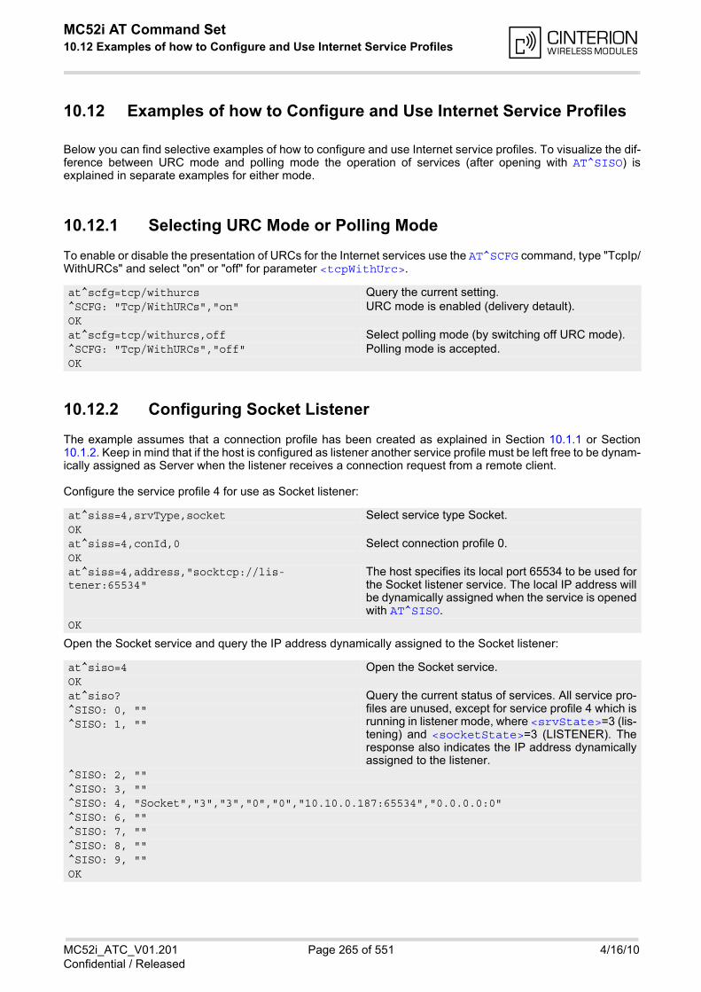
MC52i AT Command Set 10.12 Examples of how to Configure and Use Internet Service Profiles
MC52i_ATC_V01.201 Page 265 of 551 4/16/10Confidential / Released
10.12 Examples of how to Configure and Use Internet Service Profiles
Below you can find selective examples of how to configure and use Internet service profiles. To visualize the dif-ference between URC mode and polling mode the operation of services (after opening with AT^SISO) isexplained in separate examples for either mode.
10.12.1 Selecting URC Mode or Polling Mode
To enable or disable the presentation of URCs for the Internet services use the AT^SCFG command, type "TcpIp/WithURCs" and select "on" or "off" for parameter <tcpWithUrc>.
10.12.2 Configuring Socket Listener
The example assumes that a connection profile has been created as explained in Section 10.1.1 or Section10.1.2. Keep in mind that if the host is configured as listener another service profile must be left free to be dynam-ically assigned as Server when the listener receives a connection request from a remote client.
Configure the service profile 4 for use as Socket listener:
Open the Socket service and query the IP address dynamically assigned to the Socket listener:
at^scfg=tcp/withurcs Query the current setting.^SCFG: "Tcp/WithURCs","on" URC mode is enabled (delivery detault).OKat^scfg=tcp/withurcs,off Select polling mode (by switching off URC mode).^SCFG: "Tcp/WithURCs","off" Polling mode is accepted.OK
at^siss=4,srvType,socket Select service type Socket.OKat^siss=4,conId,0 Select connection profile 0.OKat^siss=4,address,"socktcp://lis-tener:65534"
The host specifies its local port 65534 to be used forthe Socket listener service. The local IP address willbe dynamically assigned when the service is openedwith AT^SISO.
OK
at^siso=4 Open the Socket service.OKat^siso? Query the current status of services. All service pro-
files are unused, except for service profile 4 which isrunning in listener mode, where <srvState>=3 (lis-tening) and <socketState>=3 (LISTENER). Theresponse also indicates the IP address dynamicallyassigned to the listener.
^SISO: 0, ""^SISO: 1, ""
^SISO: 2, ""^SISO: 3, ""^SISO: 4, "Socket","3","3","0","0","10.10.0.187:65534","0.0.0.0:0"^SISO: 6, ""^SISO: 7, ""^SISO: 8, ""^SISO: 9, ""OK
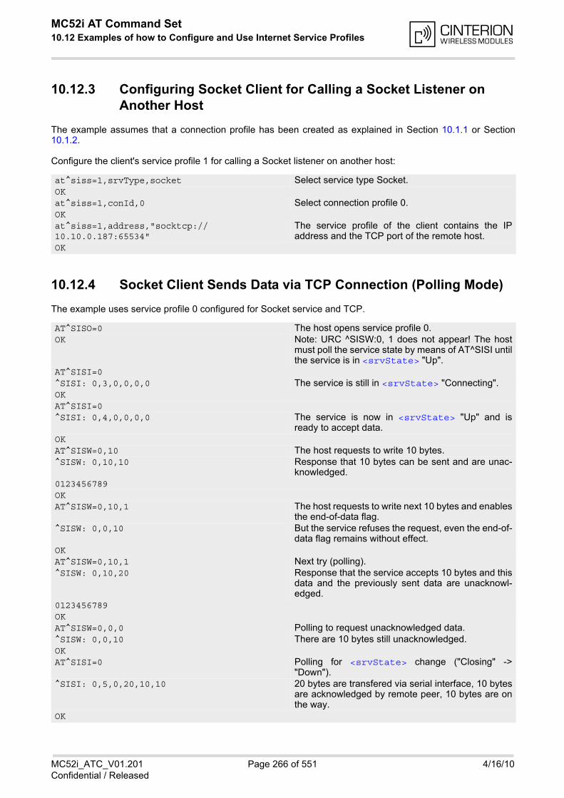
MC52i AT Command Set 10.12 Examples of how to Configure and Use Internet Service Profiles
MC52i_ATC_V01.201 Page 266 of 551 4/16/10Confidential / Released
10.12.3 Configuring Socket Client for Calling a Socket Listener on Another Host
The example assumes that a connection profile has been created as explained in Section 10.1.1 or Section10.1.2.
Configure the client's service profile 1 for calling a Socket listener on another host:
10.12.4 Socket Client Sends Data via TCP Connection (Polling Mode)
The example uses service profile 0 configured for Socket service and TCP.
at^siss=1,srvType,socket Select service type Socket.OKat^siss=1,conId,0 Select connection profile 0.OKat^siss=1,address,"socktcp://10.10.0.187:65534"
The service profile of the client contains the IPaddress and the TCP port of the remote host.
OK
AT^SISO=0 The host opens service profile 0.OK Note: URC ^SISW:0, 1 does not appear! The host
must poll the service state by means of AT^SISI untilthe service is in <srvState> "Up".
AT^SISI=0^SISI: 0,3,0,0,0,0 The service is still in <srvState> "Connecting".OKAT^SISI=0^SISI: 0,4,0,0,0,0 The service is now in <srvState> "Up" and is
ready to accept data.OKAT^SISW=0,10 The host requests to write 10 bytes.^SISW: 0,10,10 Response that 10 bytes can be sent and are unac-
knowledged.0123456789OKAT^SISW=0,10,1 The host requests to write next 10 bytes and enables
the end-of-data flag.^SISW: 0,0,10 But the service refuses the request, even the end-of-
data flag remains without effect.OKAT^SISW=0,10,1 Next try (polling).^SISW: 0,10,20 Response that the service accepts 10 bytes and this
data and the previously sent data are unacknowl-edged.
0123456789OKAT^SISW=0,0,0 Polling to request unacknowledged data.^SISW: 0,0,10 There are 10 bytes still unacknowledged.OKAT^SISI=0 Polling for <srvState> change ("Closing" ->
"Down").^SISI: 0,5,0,20,10,10 20 bytes are transfered via serial interface, 10 bytes
are acknowledged by remote peer, 10 bytes are onthe way.
OK
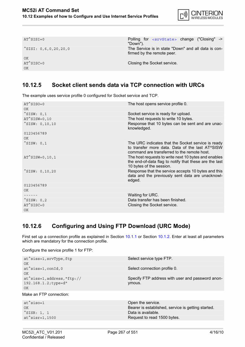
MC52i AT Command Set 10.12 Examples of how to Configure and Use Internet Service Profiles
MC52i_ATC_V01.201 Page 267 of 551 4/16/10Confidential / Released
10.12.5 Socket client sends data via TCP connection with URCs
The example uses service profile 0 configured for Socket service and TCP.
10.12.6 Configuring and Using FTP Download (URC Mode)
First set up a connection profile as explained in Section 10.1.1 or Section 10.1.2. Enter at least all parameterswhich are mandatory for the connection profile.
Configure the service profile 1 for FTP:
Make an FTP connection:
AT^SISI=0 Polling for <srvState> change ("Closing" ->"Down").
^SISI: 0,6,0,20,20,0 The Service is in state "Down" and all data is con-firmed by the remote peer.
OKAT^SISC=0 Closing the Socket service.OK
AT^SISO=0 The host opens service profile 0.OK^SISW: 0,1 Socket service is ready for upload.AT^SISW=0,10 The host requests to write 10 bytes.^SISW: 0,10,10 Response that 10 bytes can be sent and are unac-
knowledged.0123456789OK^SISW: 0,1 The URC indicates that the Socket service is ready
to transfer more data. Data of the last AT^SISWcommand are transferred to the remote host.
AT^SISW=0,10,1 The host requests to write next 10 bytes and enablesthe end-of-data flag to notify that these are the last10 bytes of the session.
^SISW: 0,10,20 Response that the service accepts 10 bytes and thisdata and the previously sent data are unacknowl-edged.
0123456789OK------ Waiting for URC. ^SISW: 0,2 Data transfer has been finished. AT^SISC=0 Closing the Socket service. OK
at^siss=1,srvType,ftp Select service type FTP.OKat^siss=1,conId,0 Select connection profile 0.OKat^siss=1,address,"ftp://192.168.1.2;type=d"
Specify FTP address with user and password anon-ymous.
OK
at^siso=1 Open the service.OK Bearer is established, service is getting started.^SISR: 1, 1 Data is available.at^sisr=1,1500 Request to read 1500 bytes.
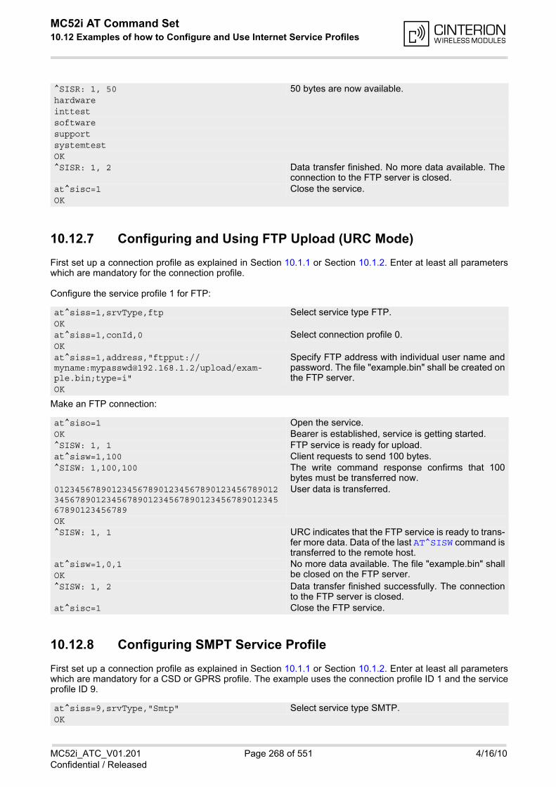
MC52i AT Command Set 10.12 Examples of how to Configure and Use Internet Service Profiles
MC52i_ATC_V01.201 Page 268 of 551 4/16/10Confidential / Released
10.12.7 Configuring and Using FTP Upload (URC Mode)
First set up a connection profile as explained in Section 10.1.1 or Section 10.1.2. Enter at least all parameterswhich are mandatory for the connection profile.
Configure the service profile 1 for FTP:
Make an FTP connection:
10.12.8 Configuring SMPT Service Profile
First set up a connection profile as explained in Section 10.1.1 or Section 10.1.2. Enter at least all parameterswhich are mandatory for a CSD or GPRS profile. The example uses the connection profile ID 1 and the serviceprofile ID 9.
^SISR: 1, 50 50 bytes are now available.hardwareinttestsoftwaresupportsystemtestOK^SISR: 1, 2 Data transfer finished. No more data available. The
connection to the FTP server is closed.at^sisc=1 Close the service.OK
at^siss=1,srvType,ftp Select service type FTP.OKat^siss=1,conId,0 Select connection profile 0.OKat^siss=1,address,"ftpput://myname:[email protected]/upload/exam-ple.bin;type=i"
Specify FTP address with individual user name andpassword. The file "example.bin" shall be created onthe FTP server.
OK
at^siso=1 Open the service.OK Bearer is established, service is getting started.^SISW: 1, 1 FTP service is ready for upload.at^sisw=1,100 Client requests to send 100 bytes.^SISW: 1,100,100 The write command response confirms that 100
bytes must be transferred now.0123456789012345678901234567890123456789012345678901234567890123456789012345678901234567890123456789
User data is transferred.
OK^SISW: 1, 1 URC indicates that the FTP service is ready to trans-
fer more data. Data of the last AT^SISW command istransferred to the remote host.
at^sisw=1,0,1 No more data available. The file "example.bin" shallbe closed on the FTP server.OK
^SISW: 1, 2 Data transfer finished successfully. The connectionto the FTP server is closed.
at^sisc=1 Close the FTP service.
at^siss=9,srvType,"Smtp" Select service type SMTP.OK

MC52i AT Command Set 10.12 Examples of how to Configure and Use Internet Service Profiles
MC52i_ATC_V01.201 Page 269 of 551 4/16/10Confidential / Released
10.12.9 Sending Email (URC Mode)
This example uses the service profile described in Section 10.12.8.
at^siss=9,alphabet,"1" Choose ASCII alphabet.OKat^siss=9,conId,"1" Select connection profile 1.OKat^siss=9,address,"192.168.1.2" Specify SMTP server address.OKat^siss=9,user,"subscriber1" Specify sender's user name required for SMTP
authentication.OKat^siss=9,passwd,"subscr1" Specify password used by the sender for SMTP
authentication.OKat^siss=9,smFrom,"[email protected]"
Sender's email address.
OKat^siss=9,smRcpt,"[email protected]"
Recipient's email address.
OKat^siss=9,smSubj,"Meeting Request Sunday Morning"
Enter text for subject field.
OKat^siss=9,smAuth,"1" Sender name and password can be used for SMTP
authentication.OKat^siss? To check the profile enter the AT^SISS read com-
mand. The response includes the values of all 10connection profiles. In this example, no values areset for the profiles 0 through 8. Service profile 9 con-tains the values specified above and the values auto-matically assumed by default.
^SISS: 0, "srvType", ""^SISS: 1, "srvType", ""^SISS: 2, "srvType", ""^SISS: 3, "srvType", ""^SISS: 4, "srvType", ""^SISS: 6, "srvType", ""^SISS: 7, "srvType", ""^SISS: 8, "srvType", ""^SISS: 9, "srvType", "Smtp"^SISS: 9, "conId", "1"^SISS: 9, "alphabet", "1"^SISS: 9, "address", "192.168.1.2"^SISS: 9, "user", "subscriber1"^SISS: 9, "passwd", "*******"^SISS: 9, "smFrom", "[email protected]"^SISS: 9, "smRcpt", "[email protected]"^SISS: 9, "smCC", ""^SISS: 9, "smSubj", "Meeting Request Sunday Morning"^SISS: 9, "smHdr", ""^SISS: 9, "tcPort", "25" Default: TCP port number commonly used for SMTP.^SISS: 9, "smAuth", "1"^SISS: 9, "tcpMR", "10" Default: Number of retransmission attempts for TCP
packets is 10 (= default of AT^SCFG).^SISS: 9, "tcpOT", "6000" Default: Timeout before closing outstanding TCP
connection is 6000 sec (= default of AT^SCFG).OK
at^siso=9 Open the service, i.e. start to send the email. OK
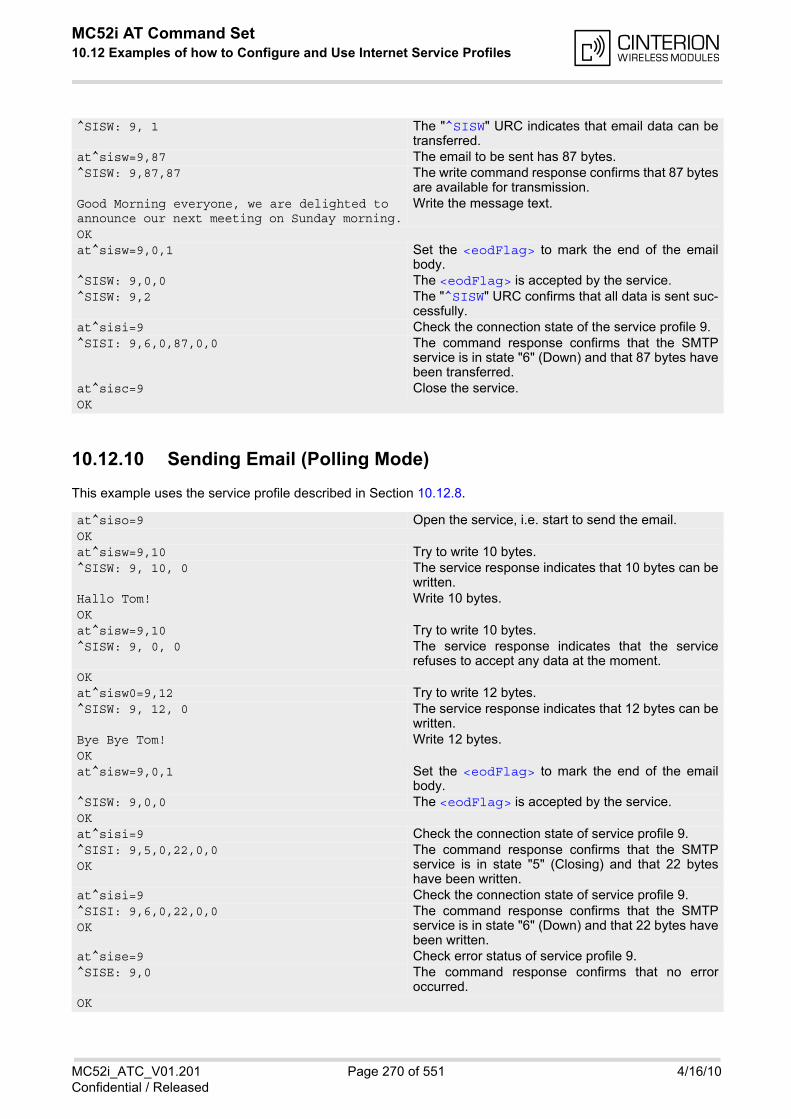
MC52i AT Command Set 10.12 Examples of how to Configure and Use Internet Service Profiles
MC52i_ATC_V01.201 Page 270 of 551 4/16/10Confidential / Released
10.12.10 Sending Email (Polling Mode)
This example uses the service profile described in Section 10.12.8.
^SISW: 9, 1 The "^SISW" URC indicates that email data can betransferred.
at^sisw=9,87 The email to be sent has 87 bytes. ^SISW: 9,87,87 The write command response confirms that 87 bytes
are available for transmission. Good Morning everyone, we are delighted to announce our next meeting on Sunday morning.
Write the message text.
OKat^sisw=9,0,1 Set the <eodFlag> to mark the end of the email
body.^SISW: 9,0,0 The <eodFlag> is accepted by the service.^SISW: 9,2 The "^SISW" URC confirms that all data is sent suc-
cessfully.at^sisi=9 Check the connection state of the service profile 9. ^SISI: 9,6,0,87,0,0 The command response confirms that the SMTP
service is in state "6" (Down) and that 87 bytes havebeen transferred.
at^sisc=9 Close the service. OK
at^siso=9 Open the service, i.e. start to send the email. OKat^sisw=9,10 Try to write 10 bytes.^SISW: 9, 10, 0 The service response indicates that 10 bytes can be
written. Hallo Tom! Write 10 bytes. OKat^sisw=9,10 Try to write 10 bytes.^SISW: 9, 0, 0 The service response indicates that the service
refuses to accept any data at the moment. OKat^sisw0=9,12 Try to write 12 bytes.^SISW: 9, 12, 0 The service response indicates that 12 bytes can be
written. Bye Bye Tom! Write 12 bytes. OKat^sisw=9,0,1 Set the <eodFlag> to mark the end of the email
body.^SISW: 9,0,0 The <eodFlag> is accepted by the service.OKat^sisi=9 Check the connection state of service profile 9. ^SISI: 9,5,0,22,0,0 The command response confirms that the SMTP
service is in state "5" (Closing) and that 22 byteshave been written.
OK
at^sisi=9 Check the connection state of service profile 9. ^SISI: 9,6,0,22,0,0 The command response confirms that the SMTP
service is in state "6" (Down) and that 22 bytes havebeen written.
OK
at^sise=9 Check error status of service profile 9. ^SISE: 9,0 The command response confirms that no error
occurred. OK
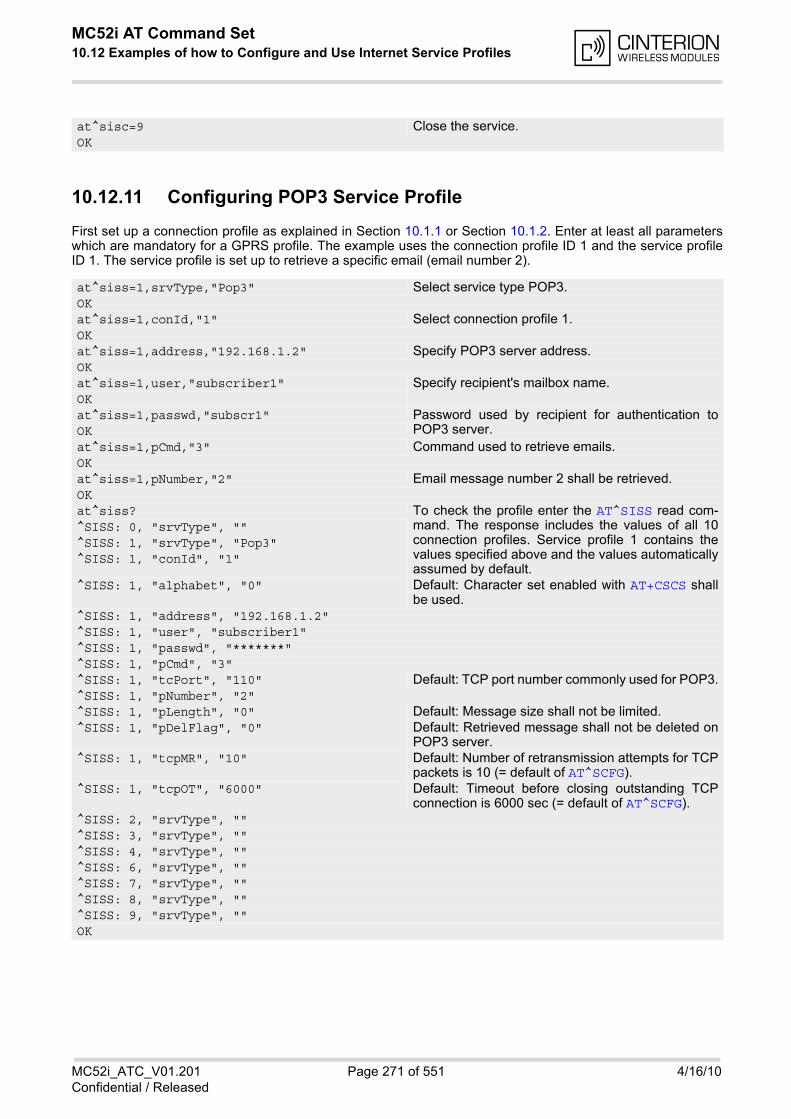
MC52i AT Command Set 10.12 Examples of how to Configure and Use Internet Service Profiles
MC52i_ATC_V01.201 Page 271 of 551 4/16/10Confidential / Released
10.12.11 Configuring POP3 Service Profile
First set up a connection profile as explained in Section 10.1.1 or Section 10.1.2. Enter at least all parameterswhich are mandatory for a GPRS profile. The example uses the connection profile ID 1 and the service profileID 1. The service profile is set up to retrieve a specific email (email number 2).
at^sisc=9 Close the service. OK
at^siss=1,srvType,"Pop3" Select service type POP3.OKat^siss=1,conId,"1" Select connection profile 1.OKat^siss=1,address,"192.168.1.2" Specify POP3 server address.OKat^siss=1,user,"subscriber1" Specify recipient's mailbox name.OKat^siss=1,passwd,"subscr1" Password used by recipient for authentication to
POP3 server.OKat^siss=1,pCmd,"3" Command used to retrieve emails.OKat^siss=1,pNumber,"2" Email message number 2 shall be retrieved. OKat^siss? To check the profile enter the AT^SISS read com-
mand. The response includes the values of all 10connection profiles. Service profile 1 contains thevalues specified above and the values automaticallyassumed by default.
^SISS: 0, "srvType", ""^SISS: 1, "srvType", "Pop3"^SISS: 1, "conId", "1"
^SISS: 1, "alphabet", "0" Default: Character set enabled with AT+CSCS shallbe used.
^SISS: 1, "address", "192.168.1.2"^SISS: 1, "user", "subscriber1"^SISS: 1, "passwd", "*******"^SISS: 1, "pCmd", "3"^SISS: 1, "tcPort", "110" Default: TCP port number commonly used for POP3.^SISS: 1, "pNumber", "2"^SISS: 1, "pLength", "0" Default: Message size shall not be limited.^SISS: 1, "pDelFlag", "0" Default: Retrieved message shall not be deleted on
POP3 server.^SISS: 1, "tcpMR", "10" Default: Number of retransmission attempts for TCP
packets is 10 (= default of AT^SCFG).^SISS: 1, "tcpOT", "6000" Default: Timeout before closing outstanding TCP
connection is 6000 sec (= default of AT^SCFG).^SISS: 2, "srvType", ""^SISS: 3, "srvType", ""^SISS: 4, "srvType", ""^SISS: 6, "srvType", ""^SISS: 7, "srvType", ""^SISS: 8, "srvType", ""^SISS: 9, "srvType", ""OK
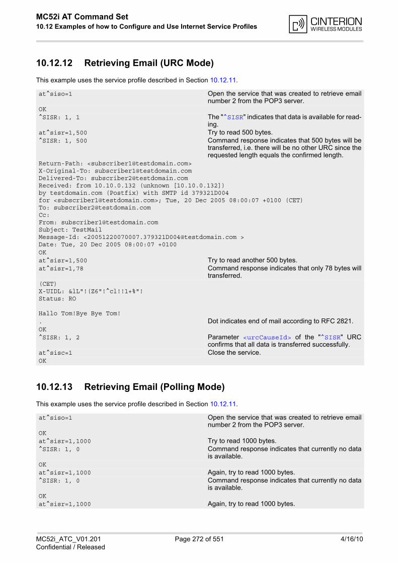
MC52i AT Command Set 10.12 Examples of how to Configure and Use Internet Service Profiles
MC52i_ATC_V01.201 Page 272 of 551 4/16/10Confidential / Released
10.12.12 Retrieving Email (URC Mode)
This example uses the service profile described in Section 10.12.11.
10.12.13 Retrieving Email (Polling Mode)
This example uses the service profile described in Section 10.12.11.
at^siso=1 Open the service that was created to retrieve emailnumber 2 from the POP3 server.
OK^SISR: 1, 1 The "^SISR" indicates that data is available for read-
ing.at^sisr=1,500 Try to read 500 bytes.^SISR: 1, 500 Command response indicates that 500 bytes will be
transferred, i.e. there will be no other URC since therequested length equals the confirmed length.
Return-Path: <[email protected]> X-Original-To: [email protected] Delivered-To: [email protected] Received: from 10.10.0.132 (unknown [10.10.0.132]) by testdomain.com (Postfix) with SMTP id 379321D004 for <[email protected]>; Tue, 20 Dec 2005 08:00:07 +0100 (CET) To: [email protected] Cc: From: [email protected] Subject: TestMail Message-Id: <[email protected] > Date: Tue, 20 Dec 2005 08:00:07 +0100OKat^sisr=1,500 Try to read another 500 bytes.at^sisr=1,78 Command response indicates that only 78 bytes will
transferred.(CET)X-UIDL: &lL"!(Z6"!^cl!!1+%"! Status: RO
Hallo Tom!Bye Bye Tom! . Dot indicates end of mail according to RFC 2821.OK^SISR: 1, 2 Parameter <urcCauseId> of the "^SISR" URC
confirms that all data is transferred successfully.at^sisc=1 Close the service. OK
at^siso=1 Open the service that was created to retrieve emailnumber 2 from the POP3 server.
OKat^sisr=1,1000 Try to read 1000 bytes.^SISR: 1, 0 Command response indicates that currently no data
is available.OKat^sisr=1,1000 Again, try to read 1000 bytes.^SISR: 1, 0 Command response indicates that currently no data
is available.OKat^sisr=1,1000 Again, try to read 1000 bytes.
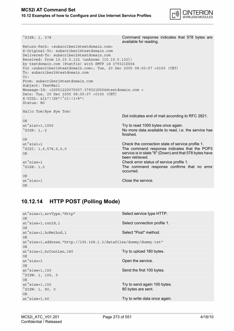
MC52i AT Command Set 10.12 Examples of how to Configure and Use Internet Service Profiles
MC52i_ATC_V01.201 Page 273 of 551 4/16/10Confidential / Released
10.12.14 HTTP POST (Polling Mode)
^SISR: 1, 578 Command response indicates that 578 bytes areavailable for reading.
Return-Path: <[email protected]> X-Original-To: [email protected] Delivered-To: [email protected] Received: from 10.10.0.132 (unknown [10.10.0.132]) by testdomain.com (Postfix) with SMTP id 379321D004 for <[email protected]>; Tue, 20 Dec 2005 08:00:07 +0100 (CET) To: [email protected] Cc: From: [email protected] Subject: TestMail Message-Id: <[email protected] > Date: Tue, 20 Dec 2005 08:00:07 +0100 (CET) X-UIDL: &lL"!(Z6"!^cl!!1+%"! Status: RO
Hallo Tom!Bye Bye Tom! . Dot indicates end of mail according to RFC 2821.OKat^sisr=1,1000 Try to read 1000 bytes once again.^SISR: 1,-2 No more data available to read, i.e. the service has
finished.OKat^sisi=1 Check the connection state of service profile 1. ^SISI: 1,6,578,0,0,0 The command response indicates that the POP3
service is in state "6" (Down) and that 578 bytes havebeen retrieved.
OK
at^sise=1 Check error status of service profile 1. ^SISE: 1,0 The command response confirms that no error
occurred. OKat^sisc=1 Close the service. OK
at^siss=1,srvType,"Http" Select service type HTTP.OKat^siss=1,conId,1 Select connection profile 1.OKat^siss=1,hcMethod,1 Select "Post" method.OKat^siss=1,address,"http://192.168.1.3/datafiles/dummy/dummy.txt"OKat^siss=1,hcContLen,180 Try to upload 180 bytes.OKat^siso=1 Open the service.OKat^sisw=1,100 Send the first 100 bytes. ^SISW: 1, 100, 0OKat^sisw=1,100 Try to send again 100 bytes.^SISW: 1, 80, 0 80 bytes are sent. OKat^sisw=1,40 Try to write data once again.
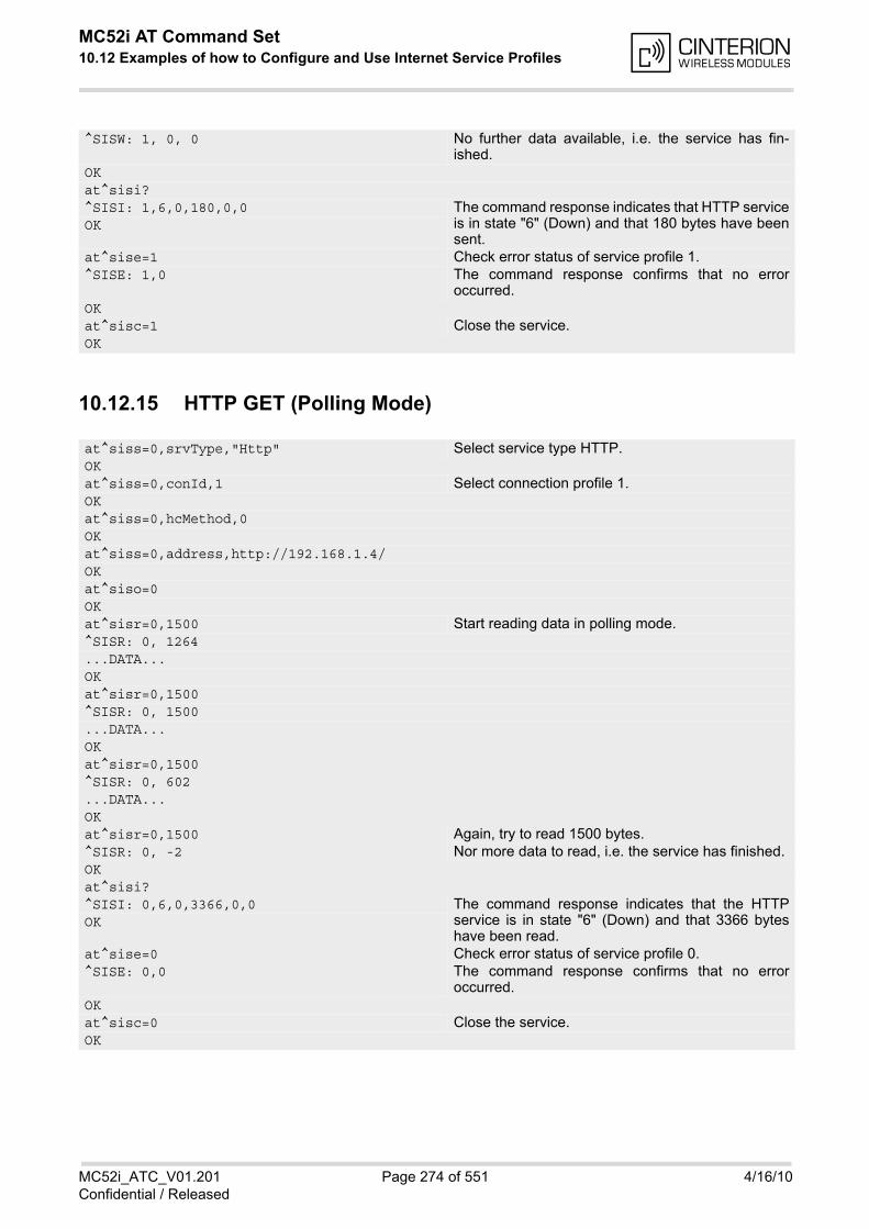
MC52i AT Command Set 10.12 Examples of how to Configure and Use Internet Service Profiles
MC52i_ATC_V01.201 Page 274 of 551 4/16/10Confidential / Released
10.12.15 HTTP GET (Polling Mode)
^SISW: 1, 0, 0 No further data available, i.e. the service has fin-ished.
OKat^sisi?^SISI: 1,6,0,180,0,0 The command response indicates that HTTP service
is in state "6" (Down) and that 180 bytes have beensent.
OK
at^sise=1 Check error status of service profile 1. ^SISE: 1,0 The command response confirms that no error
occurred. OKat^sisc=1 Close the service. OK
at^siss=0,srvType,"Http" Select service type HTTP.OKat^siss=0,conId,1 Select connection profile 1.OKat^siss=0,hcMethod,0OKat^siss=0,address,http://192.168.1.4/OKat^siso=0OKat^sisr=0,1500 Start reading data in polling mode.^SISR: 0, 1264...DATA...OKat^sisr=0,1500^SISR: 0, 1500...DATA...OKat^sisr=0,1500^SISR: 0, 602...DATA...OKat^sisr=0,1500 Again, try to read 1500 bytes.^SISR: 0, -2 Nor more data to read, i.e. the service has finished. OKat^sisi?^SISI: 0,6,0,3366,0,0 The command response indicates that the HTTP
service is in state "6" (Down) and that 3366 byteshave been read.
OK
at^sise=0 Check error status of service profile 0. ^SISE: 0,0 The command response confirms that no error
occurred. OKat^sisc=0 Close the service. OK
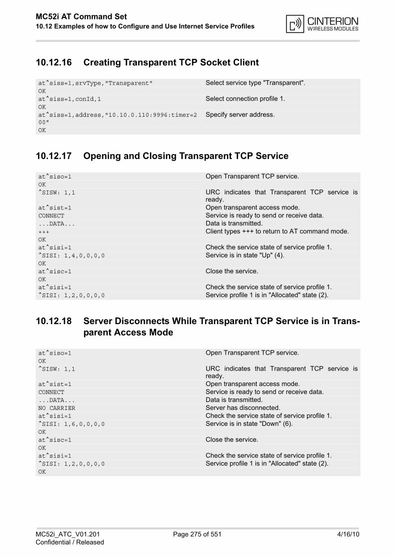
MC52i AT Command Set 10.12 Examples of how to Configure and Use Internet Service Profiles
MC52i_ATC_V01.201 Page 275 of 551 4/16/10Confidential / Released
10.12.16 Creating Transparent TCP Socket Client
10.12.17 Opening and Closing Transparent TCP Service
10.12.18 Server Disconnects While Transparent TCP Service is in Trans-parent Access Mode
at^siss=1,srvType,"Transparent" Select service type "Transparent".OKat^siss=1,conId,1 Select connection profile 1.OKat^siss=1,address,"10.10.0.110:9996:timer=200"
Specify server address.
OK
at^siso=1 Open Transparent TCP service.OK^SISW: 1,1 URC indicates that Transparent TCP service is
ready.at^sist=1 Open transparent access mode.CONNECT Service is ready to send or receive data....DATA... Data is transmitted.+++ Client types +++ to return to AT command mode.OKat^sisi=1 Check the service state of service profile 1. ^SISI: 1,4,0,0,0,0 Service is in state "Up" (4).OKat^sisc=1 Close the service. OKat^sisi=1 Check the service state of service profile 1. ^SISI: 1,2,0,0,0,0 Service profile 1 is in "Allocated" state (2).
at^siso=1 Open Transparent TCP service.OK^SISW: 1,1 URC indicates that Transparent TCP service is
ready.at^sist=1 Open transparent access mode.CONNECT Service is ready to send or receive data....DATA... Data is transmitted.NO CARRIER Server has disconnected.at^sisi=1 Check the service state of service profile 1. ^SISI: 1,6,0,0,0,0 Service is in state "Down" (6).OKat^sisc=1 Close the service. OKat^sisi=1 Check the service state of service profile 1. ^SISI: 1,2,0,0,0,0 Service profile 1 is in "Allocated" state (2).OK
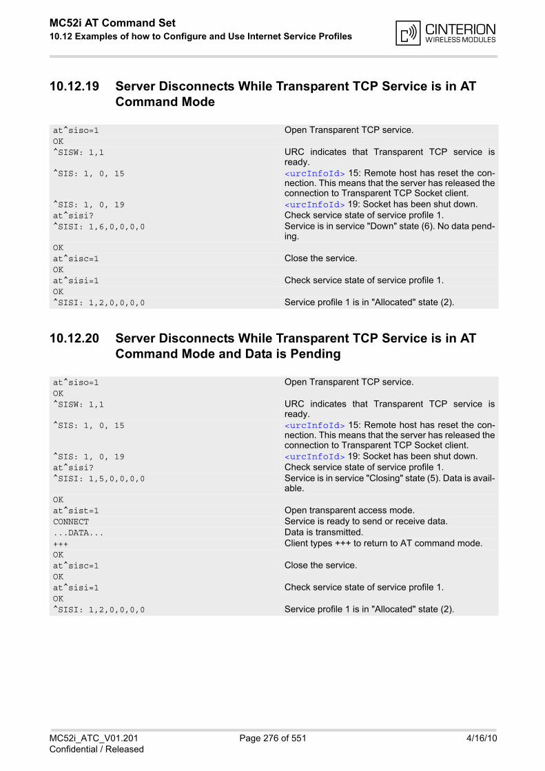
MC52i AT Command Set 10.12 Examples of how to Configure and Use Internet Service Profiles
MC52i_ATC_V01.201 Page 276 of 551 4/16/10Confidential / Released
10.12.19 Server Disconnects While Transparent TCP Service is in AT Command Mode
10.12.20 Server Disconnects While Transparent TCP Service is in AT Command Mode and Data is Pending
at^siso=1 Open Transparent TCP service.OK^SISW: 1,1 URC indicates that Transparent TCP service is
ready.^SIS: 1, 0, 15 <urcInfoId> 15: Remote host has reset the con-
nection. This means that the server has released theconnection to Transparent TCP Socket client.
^SIS: 1, 0, 19 <urcInfoId> 19: Socket has been shut down.at^sisi? Check service state of service profile 1.^SISI: 1,6,0,0,0,0 Service is in service "Down" state (6). No data pend-
ing.OKat^sisc=1 Close the service. OKat^sisi=1 Check service state of service profile 1.OK^SISI: 1,2,0,0,0,0 Service profile 1 is in "Allocated" state (2).
at^siso=1 Open Transparent TCP service.OK^SISW: 1,1 URC indicates that Transparent TCP service is
ready.^SIS: 1, 0, 15 <urcInfoId> 15: Remote host has reset the con-
nection. This means that the server has released theconnection to Transparent TCP Socket client.
^SIS: 1, 0, 19 <urcInfoId> 19: Socket has been shut down.at^sisi? Check service state of service profile 1.^SISI: 1,5,0,0,0,0 Service is in service "Closing" state (5). Data is avail-
able.OKat^sist=1 Open transparent access mode.CONNECT Service is ready to send or receive data....DATA... Data is transmitted.+++ Client types +++ to return to AT command mode.OKat^sisc=1 Close the service. OKat^sisi=1 Check service state of service profile 1.OK^SISI: 1,2,0,0,0,0 Service profile 1 is in "Allocated" state (2).
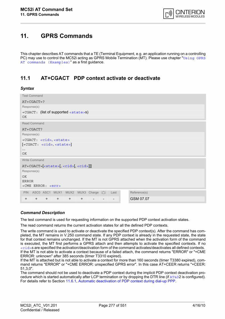
MC52i AT Command Set 11. GPRS Commands
MC52i_ATC_V01.201 Page 277 of 551 4/16/10Confidential / Released
11. GPRS Commands
This chapter describes AT commands that a TE (Terminal Equipment, e.g. an application running on a controllingPC) may use to control the MC52i acting as GPRS Mobile Termination (MT). Please use chapter "Using GPRSAT commands (Examples)" as a first guidance.
11.1 AT+CGACT PDP context activate or deactivate
Syntax
Command DescriptionThe test command is used for requesting information on the supported PDP context activation states.
The read command returns the current activation states for all the defined PDP contexts.
The write command is used to activate or deactivate the specified PDP context(s). After the command has com-pleted, the MT remains in V.250 command state. If any PDP context is already in the requested state, the statefor that context remains unchanged. If the MT is not GPRS attached when the activation form of the commandis executed, the MT first performs a GPRS attach and then attempts to activate the specified contexts. If no<cid>s are specified the activation/deactivation form of the command activates/deactivates all defined contexts. If the MT is not able to activate a context because of a failed attach, the command returns "ERROR" or "+CMEERROR: unknown" after 385 seconds (timer T3310 expired). If the MT is attached but is not able to activate a context for more than 160 seconds (timer T3380 expired), com-mand returns "ERROR" or "+CME ERROR: unspecified GPRS error". In this case AT+CEER returns "+CEER:51,3,0". The command should not be used to deactivate a PDP context during the implicit PDP context deactivation pro-cedure which is started automatically after LCP termination or by dropping the DTR line (if AT&D2 is configured).For details refer to Section 11.6.1, Automatic deactivation of PDP context during dial-up PPP.
Test Command
AT+CGACT=?Response(s)
+CGACT: (list of supported <state>s)OK
Read Command
AT+CGACT?Response(s)
+CGACT: <cid>, <state>[+CGACT: <cid>, <state>]...OK
Write Command
AT+CGACT=[<state>[, <cid>[, <cid>]]]Response(s)
OKERROR+CME ERROR: <err>
PIN ASC0 ASC1 MUX1 MUX2 MUX3 Charge Last Reference(s)
+ + + + + + - - - GSM 07.07
MC52i AT Command Set 11.1 AT+CGACT
MC52i_ATC_V01.201 Page 278 of 551 4/16/10Confidential / Released
Parameter Description
Indicates the state of PDP context activation.
0 deactivated
[1] activated
PDP Context Identifier is a numeric parameter which specifies a particular PDP context definition. The param-eter is local to the TE-MT interface and is used in other PDP context related commands.
1...2
Notes• ATH will deactivate any PDP context.
• If the MT is in dedicated mode, the write command returns "+CME ERROR: operation temporary not allowed".
• A maximum of 2 contexts can be activated at the same time, no matter on which interface. Trying to activatemore than 2 contexts will cause "+CME ERROR: operation temporary not allowed". Note that, depending onthe provider, the number of activated contexts may be further restricted. In such cases "+CME ERROR:unspecified GPRS error" will be returned and AT+CEER returns "+CEER: 50,26,0". Remember that contexts may be activated implicitly by using the ATD*98# or ATD*99# GPRS compatibilitycommands without specifying a <cid>.
• If an activated context will be deactivated without using the command AT+CGACT, then the result code "NOCARRIER" will be issued to indicate the context deactivation. This happens for example if the context deac-tivation is forced by the network or if deactivation results from a network deregistration with AT+COPS=2.
<state>(num)
<cid>(num)

MC52i AT Command Set 11.2 AT+CGANS
MC52i_ATC_V01.201 Page 279 of 551 4/16/10Confidential / Released
11.2 AT+CGANS Manual response to a network request for PDP con-text activation
Syntax
Command DescriptionThe write command requests the MT to respond to a network request for GPRS PDP context activation whichhas been signaled to the TE by the RING or CRING unsolicited result code. The <response> parameter allowsthe TE to accept or reject the request.
Parameter Description
[0] the request is rejected and the MT returns OK to the TE
1 accept and request that the PDP context be activated
a string parameter which indicates the layer 2 protocol to be used (see AT+CGDATA command)
a numeric parameter which specifies a particular PDP context definition (see AT+CGDCONT command).
Note• If <response> is 1, the following procedure is followed by the MT:
If the <L2P> parameter value is unacceptable to the MT, the MT will return an "ERROR" or "+CME ERROR:<err>" response. Otherwise, the MT issues the intermediate result code CONNECT and enters V.250 onlinedata state.A <cid> may be specified for use in the context activation request.During the PDP startup procedure the MT has the PDP type and the PDP address provided by the networkin the Request PDP context activation message. If this is in conflict with the information provided by a spec-ified <cid>, the command will fail. There will be no conflict, if the PDP type matches exactly and the PDPaddress given by the context definition for <cid> is empty or matches exactly with the address specified withthe network PDP context activation message.The context will be activated using the values for PDP type and address provided by the network, togetherwith all other information found in the PDP context definition. An APN may or may not be required, dependingon the application.
Test Command
AT+CGANS=?Response(s)
+CGANS: (list of supported <response>s), (list of supported <L2P>s)OK
Write Command
AT+CGANS=[<response>[, <L2P>[, <cid>]]]Response(s)
CONNECTNO CARRIERERROR+CME ERROR: <err>
PIN ASC0 ASC1 MUX1 MUX2 MUX3 Charge Last Reference(s)
+ + + + + + - - + GSM 07.07
<response>(num)
<L2P>(str)
<cid>(num)
MC52i AT Command Set 11.2 AT+CGANS
MC52i_ATC_V01.201 Page 280 of 551 4/16/10Confidential / Released
If no <cid> is given or if there is no matching context definition, the MT will attempt to activate the contextusing the values for PDP type and address provided by the network. The other parameters will be set to theirdefault values (see AT+CGDCONT).If activation is successful, data transfer may proceed.After data transfer is complete, and the layer 2 protocol termination procedure has completed successfully,the V.250 command state is reentered and the MT returns the final result code OK.In the event of an erroneous termination or a failure to start up, the V.250 command state is re-entered andthe MT returns the final result code NO CARRIER, or if enabled, "+CME ERROR: <err>". Attach, activate andother errors may be reported. It is also an error to issue the AT+CGANS command when there is no pendingnetwork request.The command may be used in both normal and modem compatibility modes.
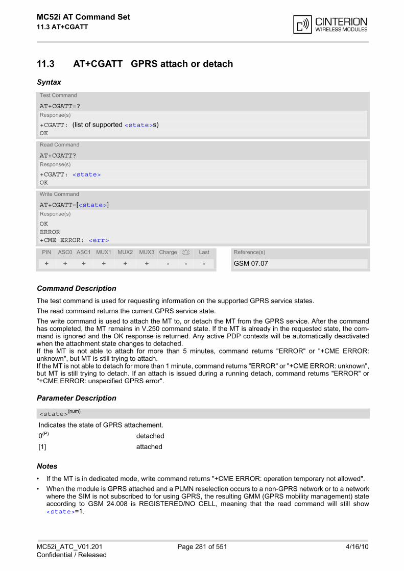
MC52i AT Command Set 11.3 AT+CGATT
MC52i_ATC_V01.201 Page 281 of 551 4/16/10Confidential / Released
11.3 AT+CGATT GPRS attach or detach
Syntax
Command DescriptionThe test command is used for requesting information on the supported GPRS service states.
The read command returns the current GPRS service state.
The write command is used to attach the MT to, or detach the MT from the GPRS service. After the commandhas completed, the MT remains in V.250 command state. If the MT is already in the requested state, the com-mand is ignored and the OK response is returned. Any active PDP contexts will be automatically deactivatedwhen the attachment state changes to detached. If the MT is not able to attach for more than 5 minutes, command returns "ERROR" or "+CME ERROR:unknown", but MT is still trying to attach. If the MT is not able to detach for more than 1 minute, command returns "ERROR" or "+CME ERROR: unknown",but MT is still trying to detach. If an attach is issued during a running detach, command returns "ERROR" or"+CME ERROR: unspecified GPRS error".
Parameter Description
Indicates the state of GPRS attachement.
0(P) detached
[1] attached
Notes• If the MT is in dedicated mode, write command returns "+CME ERROR: operation temporary not allowed".
• When the module is GPRS attached and a PLMN reselection occurs to a non-GPRS network or to a networkwhere the SIM is not subscribed to for using GPRS, the resulting GMM (GPRS mobility management) stateaccording to GSM 24.008 is REGISTERED/NO CELL, meaning that the read command will still show<state>=1.
Test Command
AT+CGATT=?Response(s)
+CGATT: (list of supported <state>s)OK
Read Command
AT+CGATT?Response(s)
+CGATT: <state>OK
Write Command
AT+CGATT=[<state>]Response(s)
OKERROR+CME ERROR: <err>
PIN ASC0 ASC1 MUX1 MUX2 MUX3 Charge Last Reference(s)
+ + + + + + - - - GSM 07.07
<state>(num)
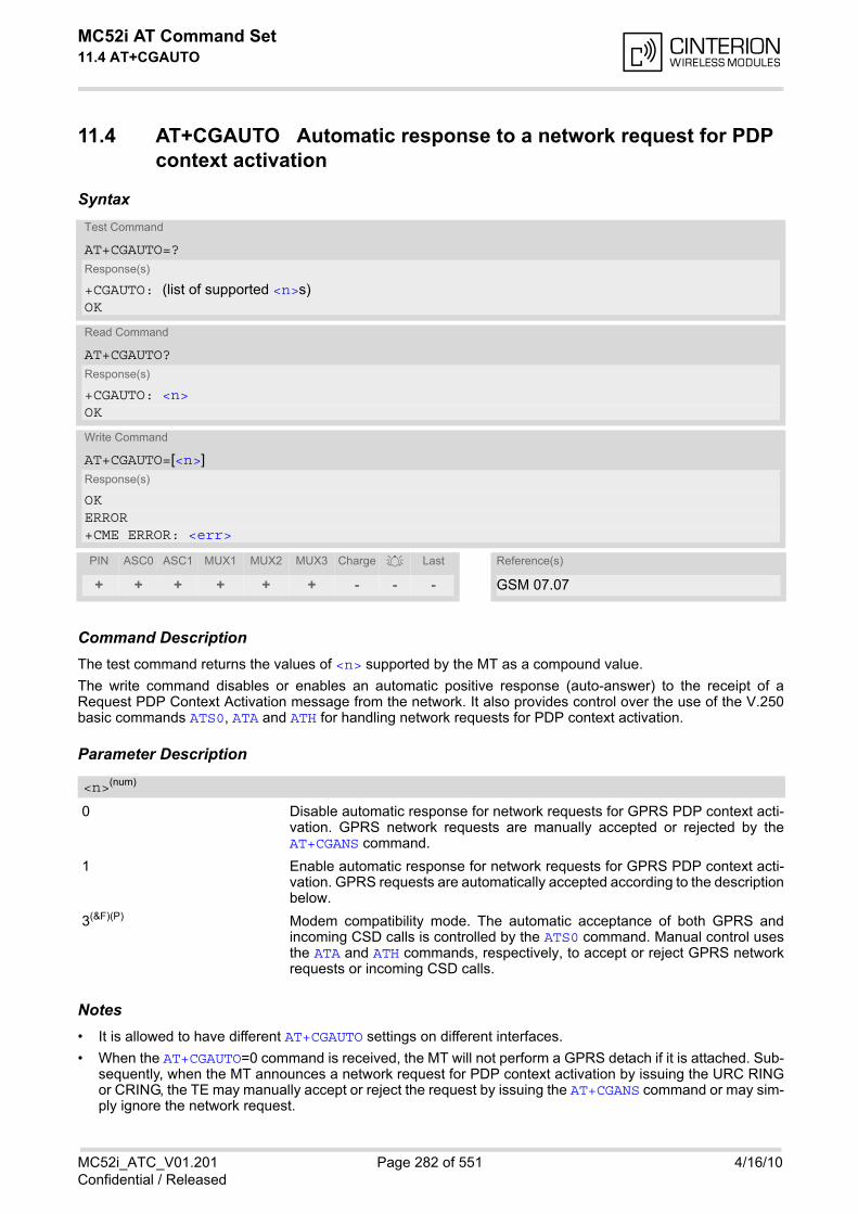
MC52i AT Command Set 11.4 AT+CGAUTO
MC52i_ATC_V01.201 Page 282 of 551 4/16/10Confidential / Released
11.4 AT+CGAUTO Automatic response to a network request for PDP context activation
Syntax
Command DescriptionThe test command returns the values of <n> supported by the MT as a compound value.
The write command disables or enables an automatic positive response (auto-answer) to the receipt of aRequest PDP Context Activation message from the network. It also provides control over the use of the V.250basic commands ATS0, ATA and ATH for handling network requests for PDP context activation.
Parameter Description
0 Disable automatic response for network requests for GPRS PDP context acti-vation. GPRS network requests are manually accepted or rejected by theAT+CGANS command.
1 Enable automatic response for network requests for GPRS PDP context acti-vation. GPRS requests are automatically accepted according to the descriptionbelow.
3(&F)(P) Modem compatibility mode. The automatic acceptance of both GPRS andincoming CSD calls is controlled by the ATS0 command. Manual control usesthe ATA and ATH commands, respectively, to accept or reject GPRS networkrequests or incoming CSD calls.
Notes• It is allowed to have different AT+CGAUTO settings on different interfaces.
• When the AT+CGAUTO=0 command is received, the MT will not perform a GPRS detach if it is attached. Sub-sequently, when the MT announces a network request for PDP context activation by issuing the URC RINGor CRING, the TE may manually accept or reject the request by issuing the AT+CGANS command or may sim-ply ignore the network request.
Test Command
AT+CGAUTO=?Response(s)
+CGAUTO: (list of supported <n>s)OK
Read Command
AT+CGAUTO?Response(s)
+CGAUTO: <n>OK
Write Command
AT+CGAUTO=[<n>]Response(s)
OKERROR+CME ERROR: <err>
PIN ASC0 ASC1 MUX1 MUX2 MUX3 Charge Last Reference(s)
+ + + + + + - - - GSM 07.07
<n>(num)
MC52i AT Command Set 11.4 AT+CGAUTO
MC52i_ATC_V01.201 Page 283 of 551 4/16/10Confidential / Released
• When the AT+CGAUTO=1 command is received, the MT will attempt to perform a GPRS attach if it is not yetattached. Failure will result in ERROR or, if enabled +CME ERROR being returned to the TE. Subsequently,the MT announces a network request for PDP context activation by issuing the URC RING to the TE, followedby the intermediate result code CONNECT. The MT then enters V.250 online data state and follows the sameprocedure as it would after having received a +CGANS=1 with no <L2P> or <cid> values specified.
• If a GPRS attach will be initiated by this command and the MT is not able to attach for more than 385 seconds(timer T3310 expired), command returns with "ERROR" or "+CME ERROR: unknown", but MT is still tryingto attach and the requested automatic mode <n> is in use.
• If a network request for PDP context activation is answered automatically and if another AT command isissued at the same time on the same interface, then this AT command is not executed. Any response belongsto the automatic context activation procedure. If the AT command which caused the collision was a circuitswitched data call, the CONNECT response does not belong to this data call but to the GPRS. This can bedetected if ATX is not set to 0. CS data call will issue CONNECT <text>, GPRS will issue CONNECT only.
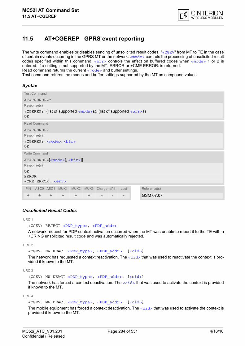
MC52i AT Command Set 11.5 AT+CGEREP
MC52i_ATC_V01.201 Page 284 of 551 4/16/10Confidential / Released
11.5 AT+CGEREP GPRS event reporting
The write command enables or disables sending of unsolicited result codes, "+CGEV" from MT to TE in the caseof certain events occurring in the GPRS MT or the network. <mode> controls the processing of unsolicited resultcodes specified within this command. <bfr> controls the effect on buffered codes when <mode> 1 or 2 isentered. If a setting is not supported by the MT, ERROR or +CME ERROR: is returned. Read command returns the current <mode> and buffer settings. Test command returns the modes and buffer settings supported by the MT as compound values.
Syntax
Unsolicited Result Codes
URC 1
+CGEV: REJECT <PDP_type>, <PDP_addr>
A network request for PDP context activation occurred when the MT was unable to report it to the TE with a+CRING unsolicited result code and was automatically rejected.
URC 2
+CGEV: NW REACT <PDP_type>, <PDP_addr>, [<cid>]
The network has requested a context reactivation. The <cid> that was used to reactivate the context is pro-vided if known to the MT.
URC 3
+CGEV: NW DEACT <PDP_type>, <PDP_addr>, [<cid>]
The network has forced a context deactivation. The <cid> that was used to activate the context is providedif known to the MT.
URC 4
+CGEV: ME DEACT <PDP_type>, <PDP_addr>, [<cid>]
The mobile equipment has forced a context deactivation. The <cid> that was used to activate the context isprovided if known to the MT.
Test Command
AT+CGEREP=?Response(s)
+CGEREP: (list of supported <mode>s), (list of supported <bfr>s)OK
Read Command
AT+CGEREP?Response(s)
+CGEREP: <mode>, <bfr>OK
Write Command
AT+CGEREP=[<mode>[, <bfr>]]Response(s)
OKERROR+CME ERROR: <err>
PIN ASC0 ASC1 MUX1 MUX2 MUX3 Charge Last Reference(s)
+ + + + + + - - - GSM 07.07
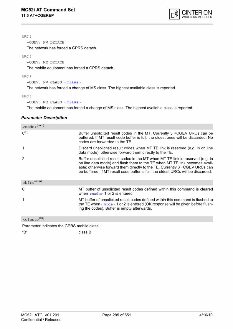
MC52i AT Command Set 11.5 AT+CGEREP
MC52i_ATC_V01.201 Page 285 of 551 4/16/10Confidential / Released
URC 5
+CGEV: NW DETACH
The network has forced a GPRS detach.
URC 6
+CGEV: ME DETACH
The mobile equipment has forced a GPRS detach.
URC 7
+CGEV: NW CLASS <class>
The network has forced a change of MS class. The highest available class is reported.
URC 8
+CGEV: ME CLASS <class>
The mobile equipment has forced a change of MS class. The highest available class is reported.
Parameter Description
0(P) Buffer unsolicited result codes in the MT. Currently 3 +CGEV URCs can bebuffered. If MT result code buffer is full, the oldest ones will be discarded. Nocodes are forwarded to the TE.
1 Discard unsolicited result codes when MT TE link is reserved (e.g. in on linedata mode); otherwise forward them directly to the TE.
2 Buffer unsolicited result codes in the MT when MT TE link is reserved (e.g. inon line data mode) and flush them to the TE when MT TE link becomes avail-able; otherwise forward them directly to the TE. Currently 3 +CGEV URCs canbe buffered. If MT result code buffer is full, the oldest URCs will be discarded.
0 MT buffer of unsolicited result codes defined within this command is clearedwhen <mode> 1 or 2 is entered
1 MT buffer of unsolicited result codes defined within this command is flushed tothe TE when <mode> 1 or 2 is entered (OK response will be given before flush-ing the codes). Buffer is empty afterwards.
Parameter indicates the GPRS mobile class.
“B“ class B
<mode>(num)
<bfr>(num)
<class>(str)
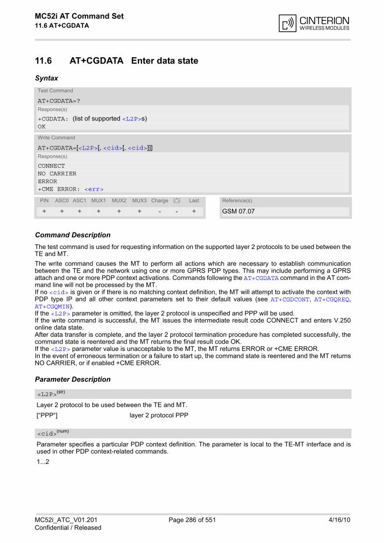
MC52i AT Command Set 11.6 AT+CGDATA
MC52i_ATC_V01.201 Page 286 of 551 4/16/10Confidential / Released
11.6 AT+CGDATA Enter data state
Syntax
Command DescriptionThe test command is used for requesting information on the supported layer 2 protocols to be used between theTE and MT.
The write command causes the MT to perform all actions which are necessary to establish communicationbetween the TE and the network using one or more GPRS PDP types. This may include performing a GPRSattach and one or more PDP context activations. Commands following the AT+CGDATA command in the AT com-mand line will not be processed by the MT. If no <cid> is given or if there is no matching context definition, the MT will attempt to activate the context withPDP type IP and all other context parameters set to their default values (see AT+CGDCONT, AT+CGQREQ,AT+CGQMIN). If the <L2P> parameter is omitted, the layer 2 protocol is unspecified and PPP will be used. If the write command is successful, the MT issues the intermediate result code CONNECT and enters V.250online data state. After data transfer is complete, and the layer 2 protocol termination procedure has completed successfully, thecommand state is reentered and the MT returns the final result code OK. If the <L2P> parameter value is unacceptable to the MT, the MT returns ERROR or +CME ERROR. In the event of erroneous termination or a failure to start up, the command state is reentered and the MT returnsNO CARRIER, or if enabled +CME ERROR.
Parameter Description
Layer 2 protocol to be used between the TE and MT.
[“PPP“] layer 2 protocol PPP
Parameter specifies a particular PDP context definition. The parameter is local to the TE-MT interface and isused in other PDP context-related commands.
1...2
Test Command
AT+CGDATA=?Response(s)
+CGDATA: (list of supported <L2P>s)OK
Write Command
AT+CGDATA=[<L2P>[, <cid>[, <cid>]]]Response(s)
CONNECTNO CARRIERERROR+CME ERROR: <err>
PIN ASC0 ASC1 MUX1 MUX2 MUX3 Charge Last Reference(s)
+ + + + + + - - + GSM 07.07
<L2P>(str)
<cid>(num)
MC52i AT Command Set 11.6 AT+CGDATA
MC52i_ATC_V01.201 Page 287 of 551 4/16/10Confidential / Released
Notes• If the MT is in dedicated mode, write command returns "+CME ERROR: operation temporary not allowed".
• It is possible to leave the GPRS data mode and enter the command mode by using the V.250 command +++.By using the command AT+CGDATA again, the data mode is reentered. Which context is used to return todata mode, depends on the supplied parameter <cid>. If no <cid> is specified, this is equivalent to using the V.250 command ATO, which is usable for GPRS con-nections too. In this case the first context will be used, which is active and already in data mode since it hasbeen activated (the internal context used for GPRS connection without explicitly specifiying a context identi-fier has the highest priority). It is possible to use AT+CGDATA to enter the data mode for a context, which is not yet in data mode since ithas been activated. With ATO this is not possible.
11.6.1 Automatic deactivation of PDP context during dial-up PPP
When using the AT+CGDATA write command or ATD*99# or ATD*98# the MT issues the intermediate resultcode CONNECT and enters V.250ter online data state. In V.250 online data state, first some LCP protocolexchange between MT and TE is performed to set up the PPP link. After successfully establishing the PPP link,the MT performs the PDP context activation procedure if the context is not already activated. As a result, the MTis in a "PDP context activated" state within the PLMN, the PPP link is established on the mobile side and themobile is ready for IP data transfer. If the TE wants to close the LCP link the MT may perform an LCP termination request procedure on PPP level.After this LCP termination procedure the MT deactivates the PDP context automatically and the MT returns toV.250 command mode and issues the final result code NO CARRIER. During the implicit PDP context deactivation procedure after LCP termination the TE may change into V.250command state (e.g. by using +++ or by toggling DTR if AT&D is set to 1) before the result NO CARRIER occurs.In this case the application should not try to deactivate the PDP context by using the commands AT+CGACT orATH. If DTR is configured to disconnect data connections (AT&D2), then the application should not toggle DTRduring the implicit PDP context deactivation and before "NO CARRIER" is received.
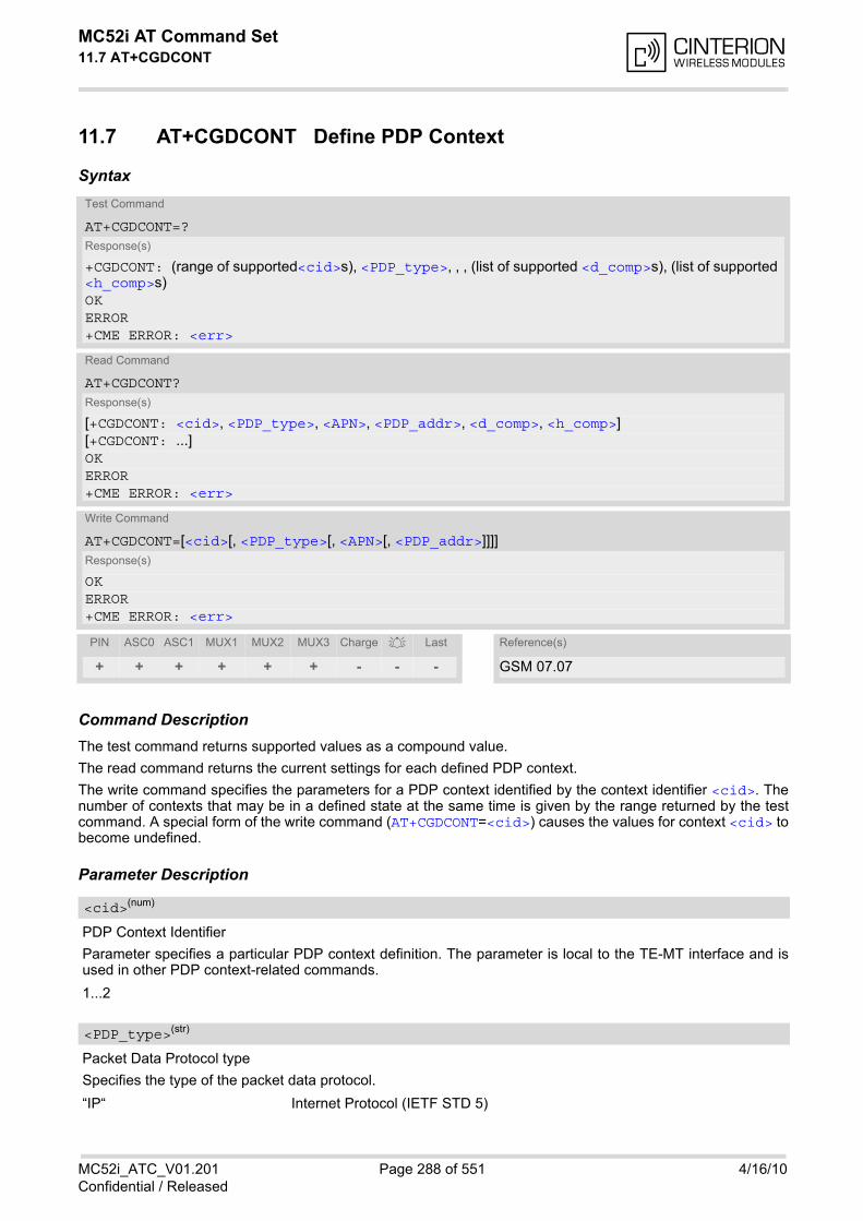
MC52i AT Command Set 11.7 AT+CGDCONT
MC52i_ATC_V01.201 Page 288 of 551 4/16/10Confidential / Released
11.7 AT+CGDCONT Define PDP Context
Syntax
Command DescriptionThe test command returns supported values as a compound value.
The read command returns the current settings for each defined PDP context.
The write command specifies the parameters for a PDP context identified by the context identifier <cid>. Thenumber of contexts that may be in a defined state at the same time is given by the range returned by the testcommand. A special form of the write command (AT+CGDCONT=<cid>) causes the values for context <cid> tobecome undefined.
Parameter Description
PDP Context Identifier
Parameter specifies a particular PDP context definition. The parameter is local to the TE-MT interface and isused in other PDP context-related commands.
1...2
Packet Data Protocol type
Specifies the type of the packet data protocol.
“IP“ Internet Protocol (IETF STD 5)
Test Command
AT+CGDCONT=?Response(s)
+CGDCONT: (range of supported<cid>s), <PDP_type>, , , (list of supported <d_comp>s), (list of supported <h_comp>s)OKERROR+CME ERROR: <err>
Read Command
AT+CGDCONT?Response(s)
[+CGDCONT: <cid>, <PDP_type>, <APN>, <PDP_addr>, <d_comp>, <h_comp>][+CGDCONT: ...]OKERROR+CME ERROR: <err>
Write Command
AT+CGDCONT=[<cid>[, <PDP_type>[, <APN>[, <PDP_addr>]]]]Response(s)
OKERROR+CME ERROR: <err>
PIN ASC0 ASC1 MUX1 MUX2 MUX3 Charge Last Reference(s)
+ + + + + + - - - GSM 07.07
<cid>(num)
<PDP_type>(str)
MC52i AT Command Set 11.7 AT+CGDCONT
MC52i_ATC_V01.201 Page 289 of 551 4/16/10Confidential / Released
Access Point Name
The logical name that is used to select the GGSN or the external packet data network. If the value is null oromitted, then the subscription value will be requested.
Packet Data Protocol address
Identifies the MT in the address space applicable to PDP (e.g. IP V4 address for PDP type IP). If the value isnull or omitted, then a value may be provided by the TE during the PDP startup procedure or, failing that, adynamic address will be requested. The read command will continue to return the null string even if an addresshas been allocated during the PDP startup procedure. The allocated address may be read using AT+CGPADDR.
Data Compression
Controls the PDP data compression (applicable for Subnetwork Dependent Convergence Protocol (SNDCP)only) 3GPP TS 44.065
[0] off
Header Compression
Controls the PDP header compression 3GPP TS 44.065, 3GPP TS 25.323
[0] off
Notes• The MT supports PDP type IP only.
• AT&F and ATZ will undefine every context which is not active or not online.
<APN>(str)
<PDP_addr>(str)
<d_comp>(num)
<h_comp>(num)
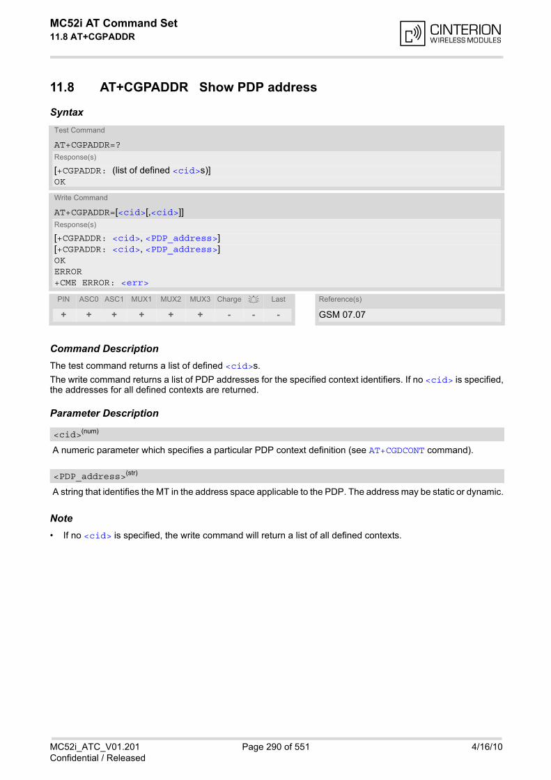
MC52i AT Command Set 11.8 AT+CGPADDR
MC52i_ATC_V01.201 Page 290 of 551 4/16/10Confidential / Released
11.8 AT+CGPADDR Show PDP address
Syntax
Command DescriptionThe test command returns a list of defined <cid>s.
The write command returns a list of PDP addresses for the specified context identifiers. If no <cid> is specified,the addresses for all defined contexts are returned.
Parameter Description
A numeric parameter which specifies a particular PDP context definition (see AT+CGDCONT command).
A string that identifies the MT in the address space applicable to the PDP. The address may be static or dynamic.
Note• If no <cid> is specified, the write command will return a list of all defined contexts.
Test Command
AT+CGPADDR=?Response(s)
[+CGPADDR: (list of defined <cid>s)]OK
Write Command
AT+CGPADDR=[<cid>[,<cid>]]Response(s)
[+CGPADDR: <cid>, <PDP_address>][+CGPADDR: <cid>, <PDP_address>]OKERROR+CME ERROR: <err>
PIN ASC0 ASC1 MUX1 MUX2 MUX3 Charge Last Reference(s)
+ + + + + + - - - GSM 07.07
<cid>(num)
<PDP_address>(str)
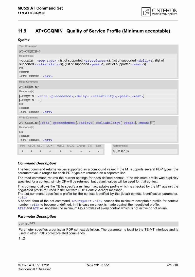
MC52i AT Command Set 11.9 AT+CGQMIN
MC52i_ATC_V01.201 Page 291 of 551 4/16/10Confidential / Released
11.9 AT+CGQMIN Quality of Service Profile (Minimum acceptable)
Syntax
Command DescriptionThe test command returns values supported as a compound value. If the MT supports several PDP types, theparameter value ranges for each PDP type are returned on a separate line.
The read command returns the current settings for each defined context. If no minimum profile was explicitlyspecified for a context, simply OK will be returned, but default values will be used for that context.
This command allows the TE to specify a minimum acceptable profile which is checked by the MT against thenegotiated profile returned in the Activate PDP Context Accept message.The set command specifies a profile for the context identified by the (local) context identification parameter,<cid>.A special form of the set command, AT+CGQMIN= <cid> causes the minimum acceptable profile for contextnumber <cid> to become undefined. In this case no check is made against the negotiated profile. AT&F and ATZ will undefine the minimum QoS profiles of every context which is not active or not online.
Parameter Description
Parameter specifies a particular PDP context definition. The parameter is local to the TE-MT interface and isused in other PDP context-related commands.
1...2
Test Command
AT+CGQMIN=?Response(s)
+CGQMIN: <PDP_type>, (list of supported <precedence>s), (list of supported <delay>s), (list of supported <reliability>s), (list of supported <peak>s), (list of supported <mean>s)OKERROR+CME ERROR: <err>
Read Command
AT+CGQMIN?Response(s)
[+CGQMIN: <cid>, <precedence>, <delay>, <reliability>, <peak>, <mean>][+CGQMIN: ...]OKERROR+CME ERROR: <err>
Write Command
AT+CGQMIN=[<cid>[, <precedence>[, <delay>[, <reliability>[, <peak>[, <mean>]]]]]]Response(s)
OKERROR+CME ERROR: <err>
PIN ASC0 ASC1 MUX1 MUX2 MUX3 Charge Last Reference(s)
+ + + + + + - - - GSM 07.07
<cid>(num)
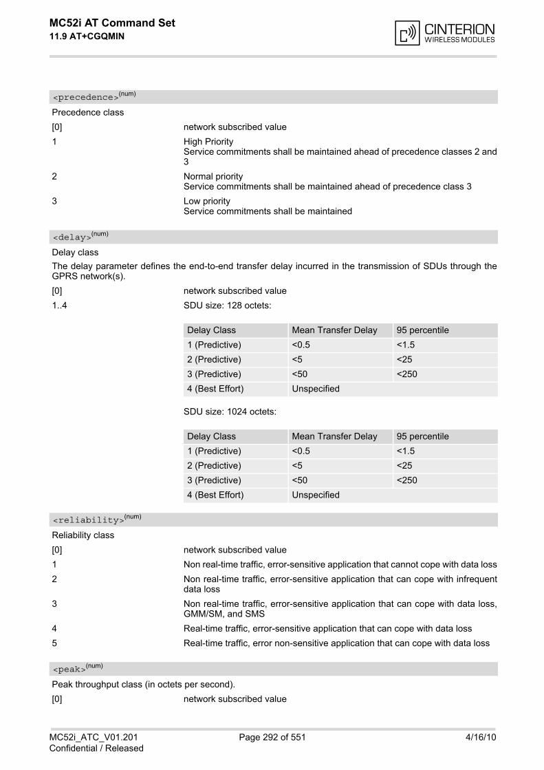
MC52i AT Command Set 11.9 AT+CGQMIN
MC52i_ATC_V01.201 Page 292 of 551 4/16/10Confidential / Released
Precedence class
[0] network subscribed value
1 High PriorityService commitments shall be maintained ahead of precedence classes 2 and3
2 Normal priorityService commitments shall be maintained ahead of precedence class 3
3 Low priorityService commitments shall be maintained
Delay class
The delay parameter defines the end-to-end transfer delay incurred in the transmission of SDUs through theGPRS network(s).
[0] network subscribed value
1..4 SDU size: 128 octets:
SDU size: 1024 octets:
Reliability class
[0] network subscribed value
1 Non real-time traffic, error-sensitive application that cannot cope with data loss
2 Non real-time traffic, error-sensitive application that can cope with infrequentdata loss
3 Non real-time traffic, error-sensitive application that can cope with data loss,GMM/SM, and SMS
4 Real-time traffic, error-sensitive application that can cope with data loss
5 Real-time traffic, error non-sensitive application that can cope with data loss
Peak throughput class (in octets per second).
[0] network subscribed value
<precedence>(num)
<delay>(num)
Delay Class Mean Transfer Delay 95 percentile
1 (Predictive) <0.5 <1.5
2 (Predictive) <5 <25
3 (Predictive) <50 <250
4 (Best Effort) Unspecified
Delay Class Mean Transfer Delay 95 percentile
1 (Predictive) <0.5 <1.5
2 (Predictive) <5 <25
3 (Predictive) <50 <250
4 (Best Effort) Unspecified
<reliability>(num)
<peak>(num)
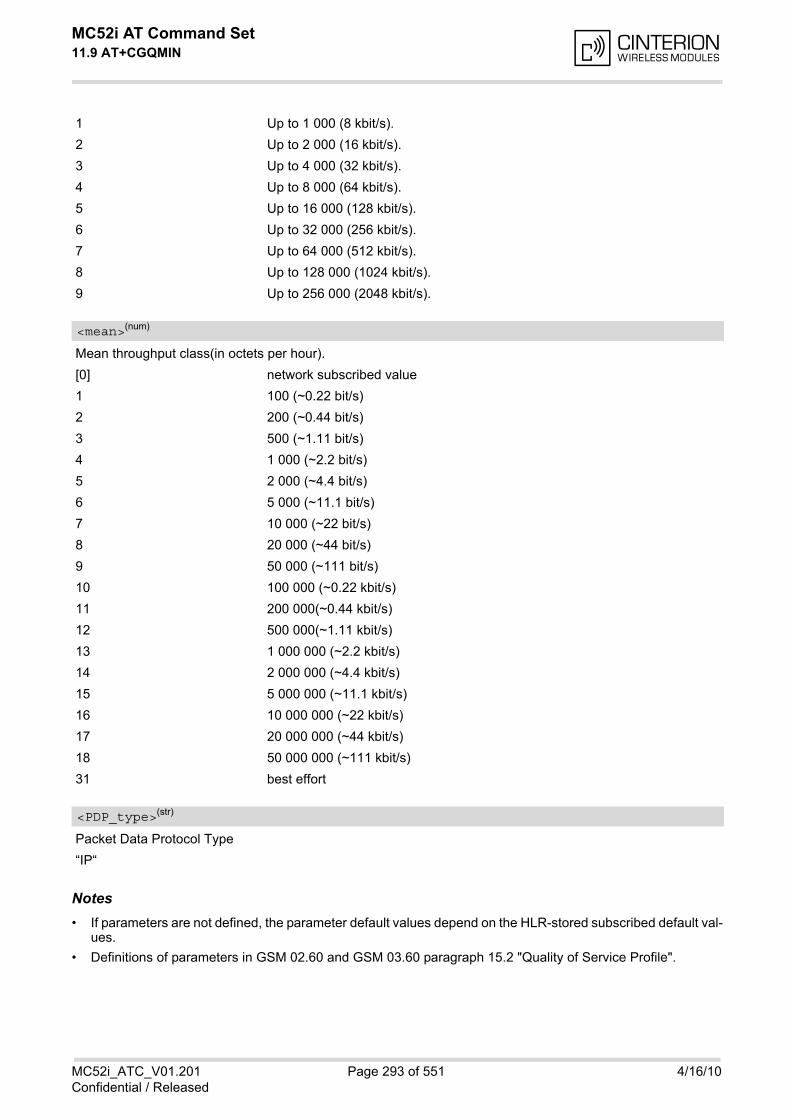
MC52i AT Command Set 11.9 AT+CGQMIN
MC52i_ATC_V01.201 Page 293 of 551 4/16/10Confidential / Released
1 Up to 1 000 (8 kbit/s).
2 Up to 2 000 (16 kbit/s).
3 Up to 4 000 (32 kbit/s).
4 Up to 8 000 (64 kbit/s).
5 Up to 16 000 (128 kbit/s).
6 Up to 32 000 (256 kbit/s).
7 Up to 64 000 (512 kbit/s).
8 Up to 128 000 (1024 kbit/s).
9 Up to 256 000 (2048 kbit/s).
Mean throughput class(in octets per hour).
[0] network subscribed value
1 100 (~0.22 bit/s)
2 200 (~0.44 bit/s)
3 500 (~1.11 bit/s)
4 1 000 (~2.2 bit/s)
5 2 000 (~4.4 bit/s)
6 5 000 (~11.1 bit/s)
7 10 000 (~22 bit/s)
8 20 000 (~44 bit/s)
9 50 000 (~111 bit/s)
10 100 000 (~0.22 kbit/s)
11 200 000(~0.44 kbit/s)
12 500 000(~1.11 kbit/s)
13 1 000 000 (~2.2 kbit/s)
14 2 000 000 (~4.4 kbit/s)
15 5 000 000 (~11.1 kbit/s)
16 10 000 000 (~22 kbit/s)
17 20 000 000 (~44 kbit/s)
18 50 000 000 (~111 kbit/s)
31 best effort
Packet Data Protocol Type
“IP“
Notes• If parameters are not defined, the parameter default values depend on the HLR-stored subscribed default val-
ues.
• Definitions of parameters in GSM 02.60 and GSM 03.60 paragraph 15.2 "Quality of Service Profile".
<mean>(num)
<PDP_type>(str)
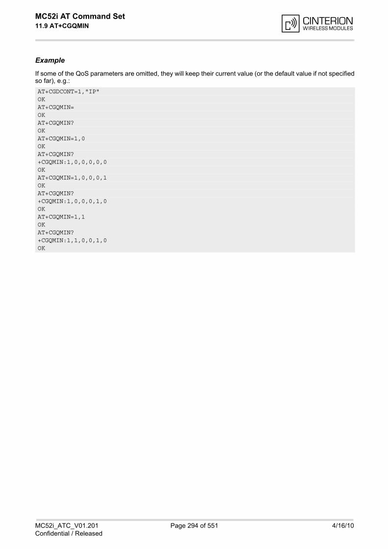
MC52i AT Command Set 11.9 AT+CGQMIN
MC52i_ATC_V01.201 Page 294 of 551 4/16/10Confidential / Released
Example
If some of the QoS parameters are omitted, they will keep their current value (or the default value if not specifiedso far), e.g.:
AT+CGDCONT=1,"IP"OKAT+CGQMIN=OKAT+CGQMIN?OKAT+CGQMIN=1,0OKAT+CGQMIN?+CGQMIN:1,0,0,0,0,0OKAT+CGQMIN=1,0,0,0,1OKAT+CGQMIN?+CGQMIN:1,0,0,0,1,0OKAT+CGQMIN=1,1OKAT+CGQMIN?+CGQMIN:1,1,0,0,1,0OK
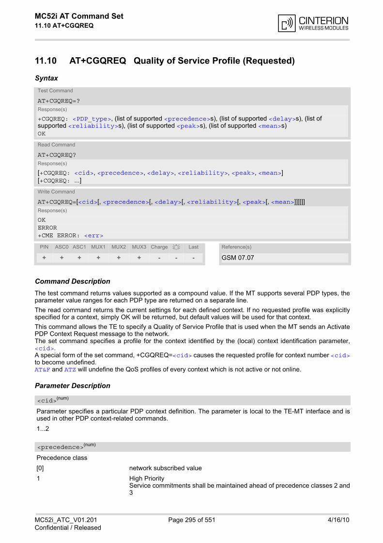
MC52i AT Command Set 11.10 AT+CGQREQ
MC52i_ATC_V01.201 Page 295 of 551 4/16/10Confidential / Released
11.10 AT+CGQREQ Quality of Service Profile (Requested)
Syntax
Command DescriptionThe test command returns values supported as a compound value. If the MT supports several PDP types, theparameter value ranges for each PDP type are returned on a separate line.
The read command returns the current settings for each defined context. If no requested profile was explicitlyspecified for a context, simply OK will be returned, but default values will be used for that context.
This command allows the TE to specify a Quality of Service Profile that is used when the MT sends an ActivatePDP Context Request message to the network.The set command specifies a profile for the context identified by the (local) context identification parameter,<cid>. A special form of the set command, +CGQREQ=<cid> causes the requested profile for context number <cid>to become undefined.AT&F and ATZ will undefine the QoS profiles of every context which is not active or not online.
Parameter Description
Parameter specifies a particular PDP context definition. The parameter is local to the TE-MT interface and isused in other PDP context-related commands.
1...2
Precedence class
[0] network subscribed value
1 High PriorityService commitments shall be maintained ahead of precedence classes 2 and3
Test Command
AT+CGQREQ=?Response(s)
+CGQREQ: <PDP_type>, (list of supported <precedence>s), (list of supported <delay>s), (list of supported <reliability>s), (list of supported <peak>s), (list of supported <mean>s)OK
Read Command
AT+CGQREQ?Response(s)
[+CGQREQ: <cid>, <precedence>, <delay>, <reliability>, <peak>, <mean>][+CGQREQ: ...]
Write Command
AT+CGQREQ=[<cid>[, <precedence>[, <delay>[, <reliability>[, <peak>[, <mean>]]]]]]Response(s)
OKERROR+CME ERROR: <err>
PIN ASC0 ASC1 MUX1 MUX2 MUX3 Charge Last Reference(s)
+ + + + + + - - - GSM 07.07
<cid>(num)
<precedence>(num)
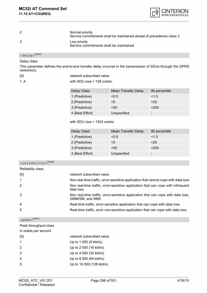
MC52i AT Command Set 11.10 AT+CGQREQ
MC52i_ATC_V01.201 Page 296 of 551 4/16/10Confidential / Released
2 Normal priorityService commitments shall be maintained ahead of precedence class 3
3 Low priorityService commitments shall be maintained
Delay class
This parameter defines the end-to-end transfer delay incurred in the transmission of SDUs through the GPRSnetwork(s).
[0] network subscribed value
1..4 with SDU size = 128 octets:
with SDU size = 1024 octets:
Reliability class
[0] network subscribed value
1 Non real-time traffic, error-sensitive application that cannot cope with data loss
2 Non real-time traffic, error-sensitive application that can cope with infrequentdata loss
3 Non real-time traffic, error-sensitive application that can cope with data loss,GMM/SM, and SMS
4 Real-time traffic, error-sensitive application that can cope with data loss
5 Real-time traffic, error non-sensitive application that can cope with data loss
Peak throughput class
in octets per second
[0] network subscribed value
1 Up to 1 000 (8 kbit/s)
2 Up to 2 000 (16 kbit/s)
3 Up to 4 000 (32 kbit/s)
4 Up to 8 000 (64 kbit/s)
5 Up to 16 000 (128 kbit/s)
<delay>(num)
Delay Class Mean Transfer Delay 95 percentile
1 (Predictive) <0.5 <1.5
2 (Predictive) <5 <25
3 (Predictive) <50 <250
4 (Best Effort) Unspecified -
Delay Class Mean Transfer Delay 95 percentile
1 (Predictive) <0.5 <1.5
2 (Predictive) <5 <25
3 (Predictive) <50 <250
4 (Best Effort) Unspecified -
<reliability>(num)
<peak>(num)
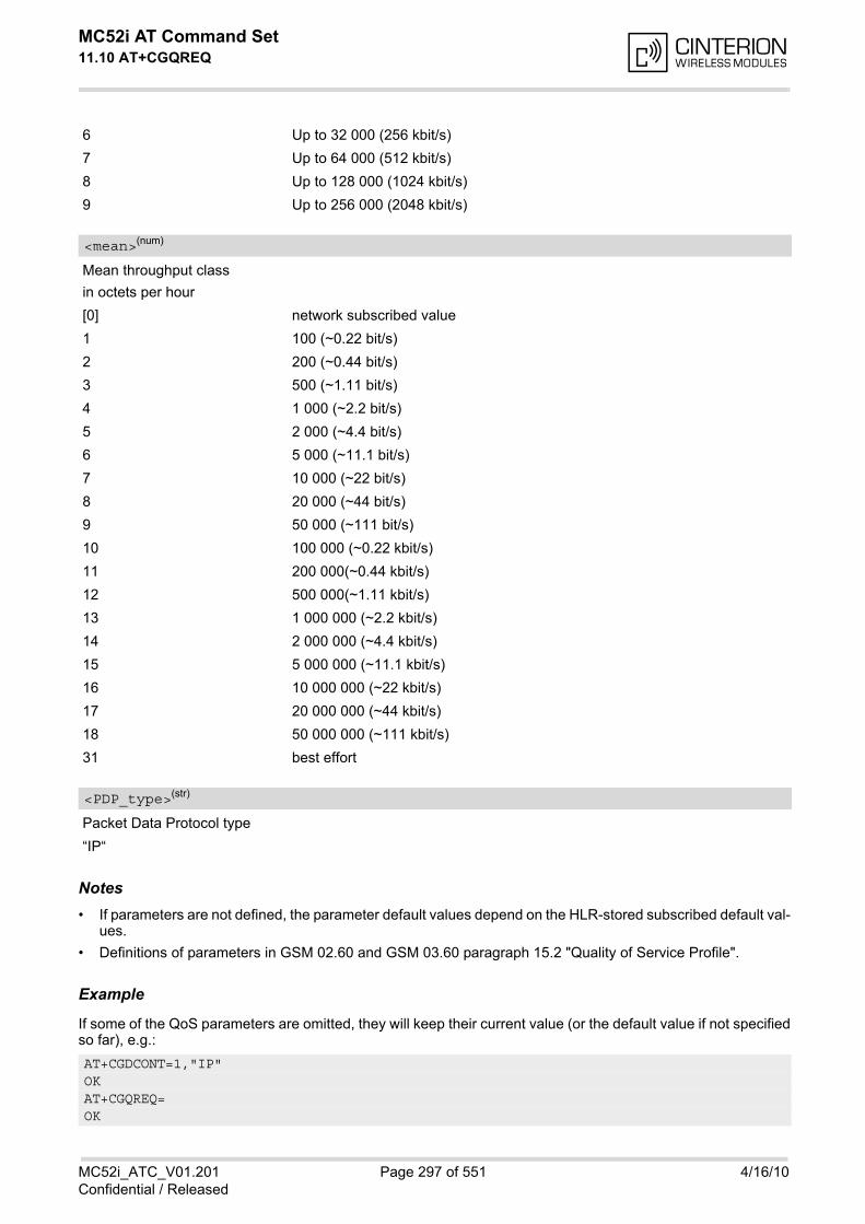
MC52i AT Command Set 11.10 AT+CGQREQ
MC52i_ATC_V01.201 Page 297 of 551 4/16/10Confidential / Released
6 Up to 32 000 (256 kbit/s)
7 Up to 64 000 (512 kbit/s)
8 Up to 128 000 (1024 kbit/s)
9 Up to 256 000 (2048 kbit/s)
Mean throughput class
in octets per hour
[0] network subscribed value
1 100 (~0.22 bit/s)
2 200 (~0.44 bit/s)
3 500 (~1.11 bit/s)
4 1 000 (~2.2 bit/s)
5 2 000 (~4.4 bit/s)
6 5 000 (~11.1 bit/s)
7 10 000 (~22 bit/s)
8 20 000 (~44 bit/s)
9 50 000 (~111 bit/s)
10 100 000 (~0.22 kbit/s)
11 200 000(~0.44 kbit/s)
12 500 000(~1.11 kbit/s)
13 1 000 000 (~2.2 kbit/s)
14 2 000 000 (~4.4 kbit/s)
15 5 000 000 (~11.1 kbit/s)
16 10 000 000 (~22 kbit/s)
17 20 000 000 (~44 kbit/s)
18 50 000 000 (~111 kbit/s)
31 best effort
Packet Data Protocol type
“IP“
Notes• If parameters are not defined, the parameter default values depend on the HLR-stored subscribed default val-
ues.
• Definitions of parameters in GSM 02.60 and GSM 03.60 paragraph 15.2 "Quality of Service Profile".
Example
If some of the QoS parameters are omitted, they will keep their current value (or the default value if not specifiedso far), e.g.:
<mean>(num)
<PDP_type>(str)
AT+CGDCONT=1,"IP"OKAT+CGQREQ=OK
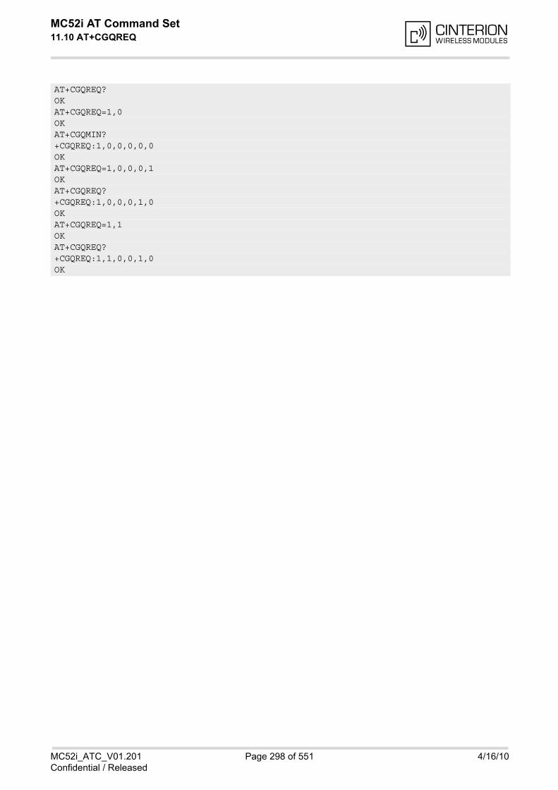
MC52i AT Command Set 11.10 AT+CGQREQ
MC52i_ATC_V01.201 Page 298 of 551 4/16/10Confidential / Released
AT+CGQREQ?OKAT+CGQREQ=1,0OKAT+CGQMIN?+CGQREQ:1,0,0,0,0,0OKAT+CGQREQ=1,0,0,0,1OKAT+CGQREQ?+CGQREQ:1,0,0,0,1,0OKAT+CGQREQ=1,1OKAT+CGQREQ?+CGQREQ:1,1,0,0,1,0OK

MC52i AT Command Set 11.11 AT+CGREG
MC52i_ATC_V01.201 Page 299 of 551 4/16/10Confidential / Released
11.11 AT+CGREG GPRS Network Registration Status
AT+CGREG write command enables presentation of URC "+CGREG: <stat>" when <n>=1 and ME's GPRS net-work registration status changes. AT+CGREG read command queries the current URC presentation status and <stat> which shows whether thenetwork has currently indicated the registration of the ME.
Syntax
Unsolicited Result Code+CGREG: <stat>
Indicates a change in the ME's GPRS network registration status.
Parameter Description
0(&F)(P) Disable network registration unsolicited result code
1 Enable network registration URC "+CGREG: <stat>"
0 Not registered, ME is not currently searching an operator to register to. The MEis in GMM state GMM-NULL or GMM-DEREGISTERED-INITIATED.GPRS service is disabled, the ME is allowed to attach to GPRS if requested bythe user.
1 Registered, home network. The ME is in GMM state GMM-REGISTERED orGMM-ROUTING-AREA-UPDATING-INITIATED INITIATED on the homePLMN
Test Command
AT+CGREG=?Response(s)
+CGREG: (list of supported <n>s)OK
Read Command
AT+CGREG?Response(s)
+CGREG: <n>, <stat>OK
Write Command
AT+CGREG=[<n>]Response(s)
OKERROR+CME ERROR: <err>
PIN ASC0 ASC1 MUX1 MUX2 MUX3 Charge Last Reference(s)
+ + + + + + - - - GSM 07.07
<n>(num)
<stat>(num)
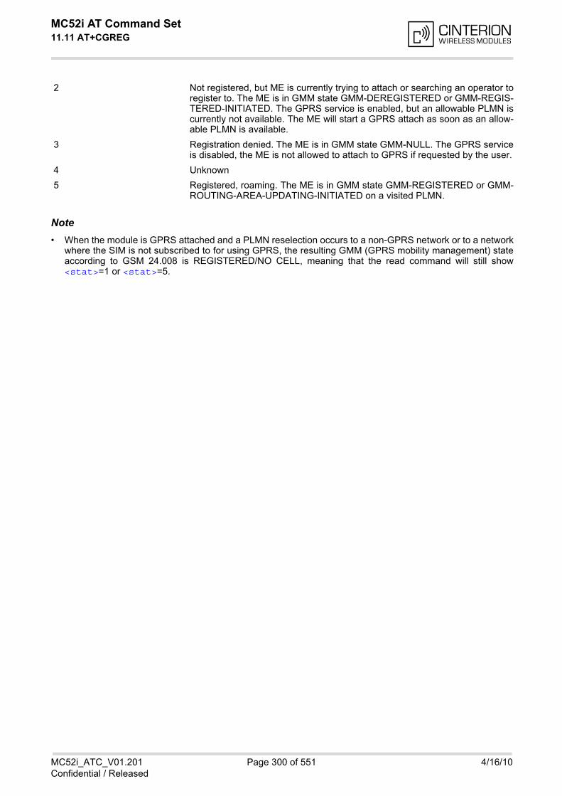
MC52i AT Command Set 11.11 AT+CGREG
MC52i_ATC_V01.201 Page 300 of 551 4/16/10Confidential / Released
2 Not registered, but ME is currently trying to attach or searching an operator toregister to. The ME is in GMM state GMM-DEREGISTERED or GMM-REGIS-TERED-INITIATED. The GPRS service is enabled, but an allowable PLMN iscurrently not available. The ME will start a GPRS attach as soon as an allow-able PLMN is available.
3 Registration denied. The ME is in GMM state GMM-NULL. The GPRS serviceis disabled, the ME is not allowed to attach to GPRS if requested by the user.
4 Unknown
5 Registered, roaming. The ME is in GMM state GMM-REGISTERED or GMM-ROUTING-AREA-UPDATING-INITIATED on a visited PLMN.
Note• When the module is GPRS attached and a PLMN reselection occurs to a non-GPRS network or to a network
where the SIM is not subscribed to for using GPRS, the resulting GMM (GPRS mobility management) stateaccording to GSM 24.008 is REGISTERED/NO CELL, meaning that the read command will still show<stat>=1 or <stat>=5.
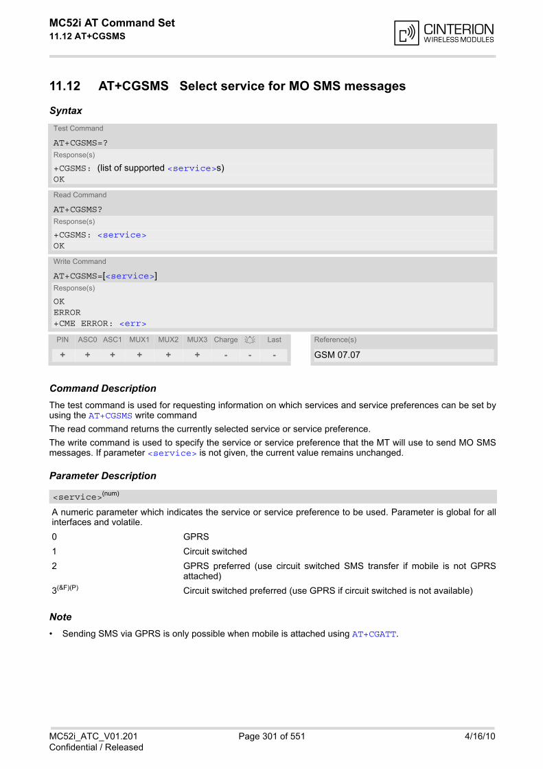
MC52i AT Command Set 11.12 AT+CGSMS
MC52i_ATC_V01.201 Page 301 of 551 4/16/10Confidential / Released
11.12 AT+CGSMS Select service for MO SMS messages
Syntax
Command DescriptionThe test command is used for requesting information on which services and service preferences can be set byusing the AT+CGSMS write command
The read command returns the currently selected service or service preference.
The write command is used to specify the service or service preference that the MT will use to send MO SMSmessages. If parameter <service> is not given, the current value remains unchanged.
Parameter Description
A numeric parameter which indicates the service or service preference to be used. Parameter is global for allinterfaces and volatile.
0 GPRS
1 Circuit switched
2 GPRS preferred (use circuit switched SMS transfer if mobile is not GPRSattached)
3(&F)(P) Circuit switched preferred (use GPRS if circuit switched is not available)
Note• Sending SMS via GPRS is only possible when mobile is attached using AT+CGATT.
Test Command
AT+CGSMS=?Response(s)
+CGSMS: (list of supported <service>s)OK
Read Command
AT+CGSMS?Response(s)
+CGSMS: <service>OK
Write Command
AT+CGSMS=[<service>]Response(s)
OKERROR+CME ERROR: <err>
PIN ASC0 ASC1 MUX1 MUX2 MUX3 Charge Last Reference(s)
+ + + + + + - - - GSM 07.07
<service>(num)
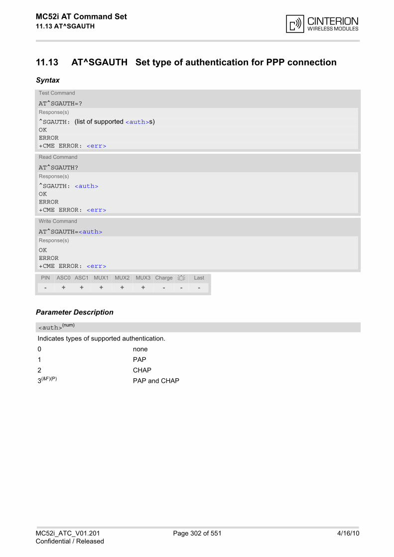
MC52i AT Command Set 11.13 AT^SGAUTH
MC52i_ATC_V01.201 Page 302 of 551 4/16/10Confidential / Released
11.13 AT^SGAUTH Set type of authentication for PPP connection
Syntax
Parameter Description
Indicates types of supported authentication.
0 none
1 PAP
2 CHAP
3(&F)(P) PAP and CHAP
Test Command
AT^SGAUTH=?Response(s)
^SGAUTH: (list of supported <auth>s)OKERROR+CME ERROR: <err>
Read Command
AT^SGAUTH?Response(s)
^SGAUTH: <auth>OKERROR+CME ERROR: <err>
Write Command
AT^SGAUTH=<auth>Response(s)
OKERROR+CME ERROR: <err>
PIN ASC0 ASC1 MUX1 MUX2 MUX3 Charge Last
- + + + + + - - -
<auth>(num)
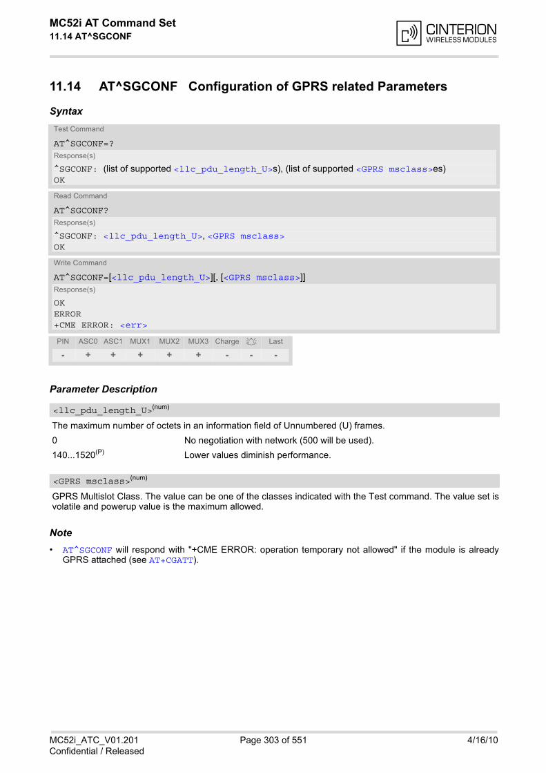
MC52i AT Command Set 11.14 AT^SGCONF
MC52i_ATC_V01.201 Page 303 of 551 4/16/10Confidential / Released
11.14 AT^SGCONF Configuration of GPRS related Parameters
Syntax
Parameter Description
The maximum number of octets in an information field of Unnumbered (U) frames.
0 No negotiation with network (500 will be used).
140...1520(P) Lower values diminish performance.
GPRS Multislot Class. The value can be one of the classes indicated with the Test command. The value set isvolatile and powerup value is the maximum allowed.
Note• AT^SGCONF will respond with "+CME ERROR: operation temporary not allowed" if the module is already
GPRS attached (see AT+CGATT).
Test Command
AT^SGCONF=?Response(s)
^SGCONF: (list of supported <llc_pdu_length_U>s), (list of supported <GPRS msclass>es)OK
Read Command
AT^SGCONF?Response(s)
^SGCONF: <llc_pdu_length_U>, <GPRS msclass>OK
Write Command
AT^SGCONF=[<llc_pdu_length_U>][, [<GPRS msclass>]]Response(s)
OKERROR+CME ERROR: <err>
PIN ASC0 ASC1 MUX1 MUX2 MUX3 Charge Last
- + + + + + - - -
<llc_pdu_length_U>(num)
<GPRS msclass>(num)
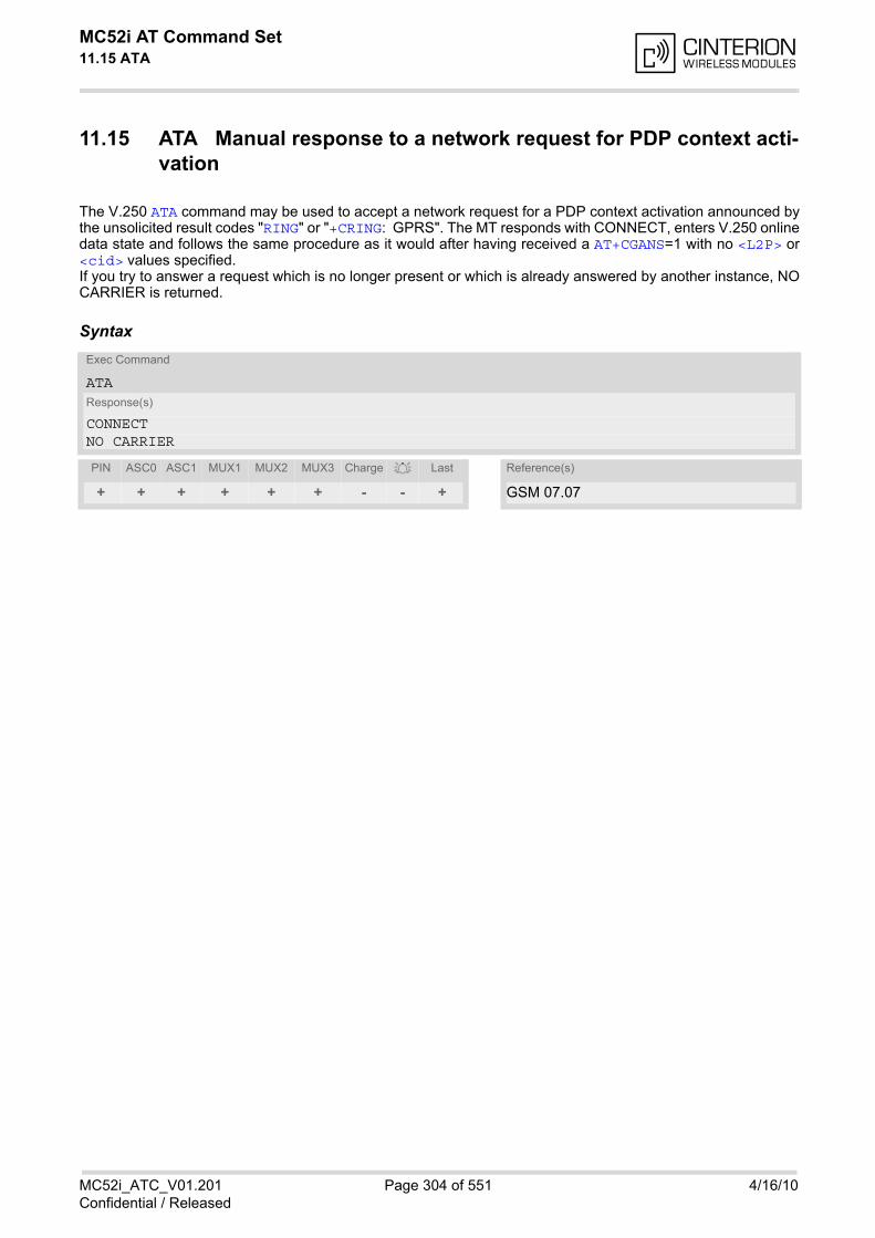
MC52i AT Command Set 11.15 ATA
MC52i_ATC_V01.201 Page 304 of 551 4/16/10Confidential / Released
11.15 ATA Manual response to a network request for PDP context acti-vation
The V.250 ATA command may be used to accept a network request for a PDP context activation announced bythe unsolicited result codes "RING" or "+CRING: GPRS". The MT responds with CONNECT, enters V.250 onlinedata state and follows the same procedure as it would after having received a AT+CGANS=1 with no <L2P> or<cid> values specified. If you try to answer a request which is no longer present or which is already answered by another instance, NOCARRIER is returned.
SyntaxExec Command
ATAResponse(s)
CONNECTNO CARRIER
PIN ASC0 ASC1 MUX1 MUX2 MUX3 Charge Last Reference(s)
+ + + + + + - - + GSM 07.07
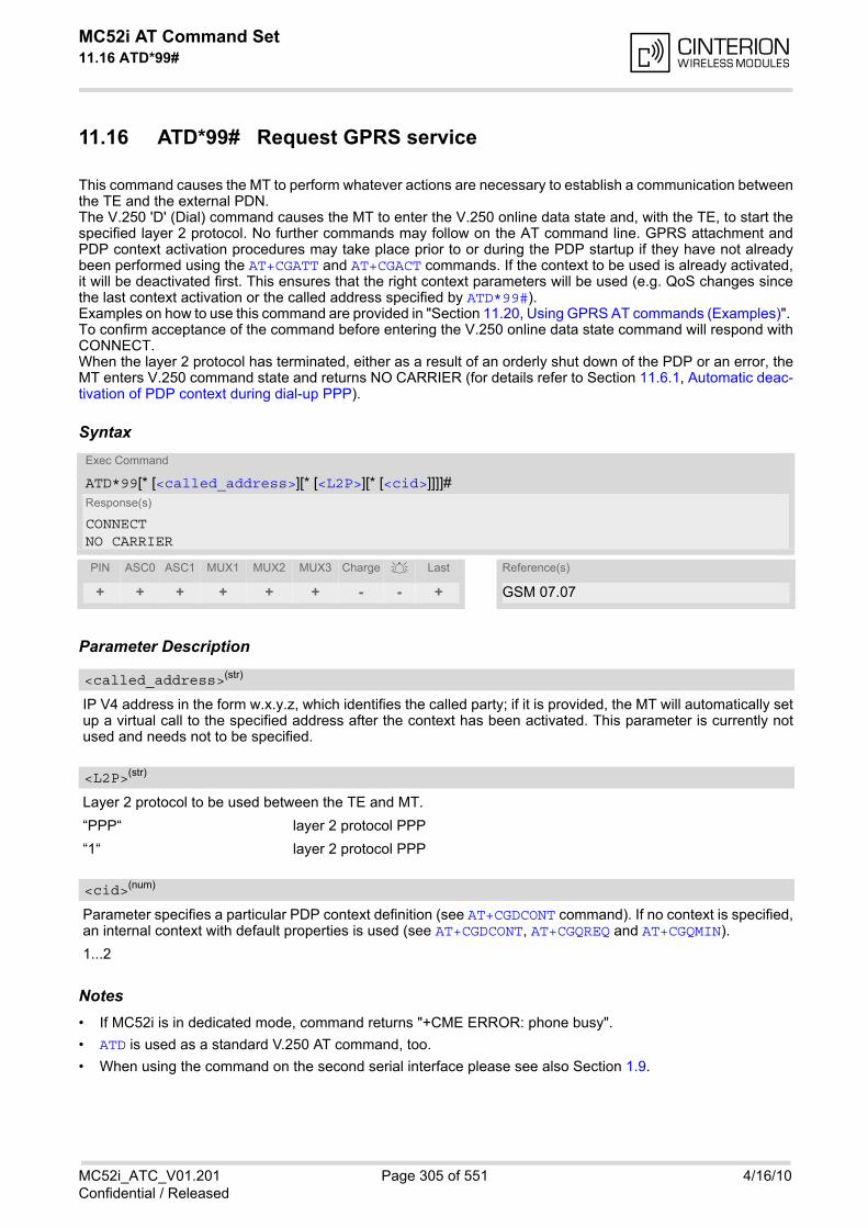
MC52i AT Command Set 11.16 ATD*99#
MC52i_ATC_V01.201 Page 305 of 551 4/16/10Confidential / Released
11.16 ATD*99# Request GPRS service
This command causes the MT to perform whatever actions are necessary to establish a communication betweenthe TE and the external PDN.The V.250 'D' (Dial) command causes the MT to enter the V.250 online data state and, with the TE, to start thespecified layer 2 protocol. No further commands may follow on the AT command line. GPRS attachment andPDP context activation procedures may take place prior to or during the PDP startup if they have not alreadybeen performed using the AT+CGATT and AT+CGACT commands. If the context to be used is already activated,it will be deactivated first. This ensures that the right context parameters will be used (e.g. QoS changes sincethe last context activation or the called address specified by ATD*99#). Examples on how to use this command are provided in "Section 11.20, Using GPRS AT commands (Examples)". To confirm acceptance of the command before entering the V.250 online data state command will respond withCONNECT. When the layer 2 protocol has terminated, either as a result of an orderly shut down of the PDP or an error, theMT enters V.250 command state and returns NO CARRIER (for details refer to Section 11.6.1, Automatic deac-tivation of PDP context during dial-up PPP).
Syntax
Parameter Description
IP V4 address in the form w.x.y.z, which identifies the called party; if it is provided, the MT will automatically setup a virtual call to the specified address after the context has been activated. This parameter is currently notused and needs not to be specified.
Layer 2 protocol to be used between the TE and MT.
“PPP“ layer 2 protocol PPP
“1“ layer 2 protocol PPP
Parameter specifies a particular PDP context definition (see AT+CGDCONT command). If no context is specified,an internal context with default properties is used (see AT+CGDCONT, AT+CGQREQ and AT+CGQMIN).
1...2
Notes• If MC52i is in dedicated mode, command returns "+CME ERROR: phone busy".
• ATD is used as a standard V.250 AT command, too.
• When using the command on the second serial interface please see also Section 1.9.
Exec Command
ATD*99[* [<called_address>][* [<L2P>][* [<cid>]]]]# Response(s)
CONNECTNO CARRIER
PIN ASC0 ASC1 MUX1 MUX2 MUX3 Charge Last Reference(s)
+ + + + + + - - + GSM 07.07
<called_address>(str)
<L2P>(str)
<cid>(num)
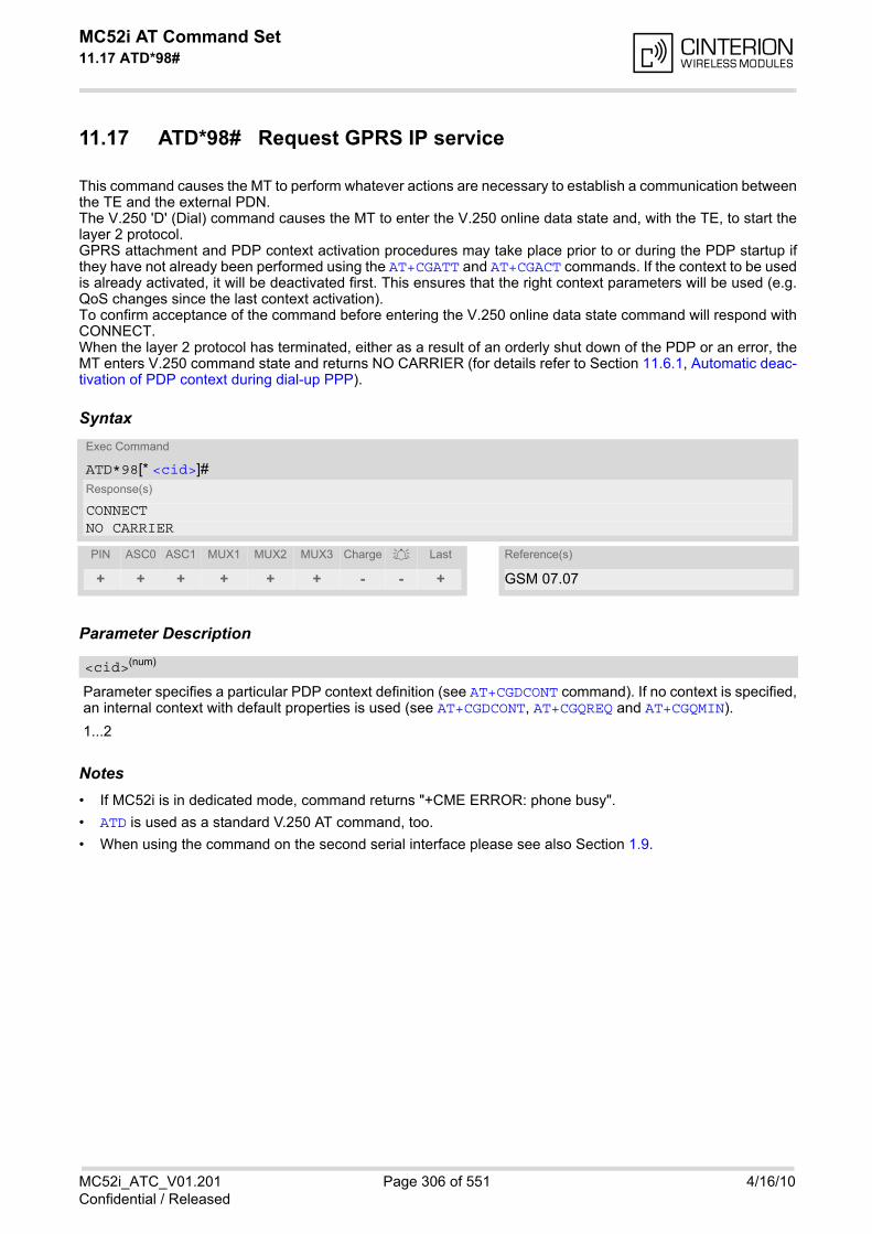
MC52i AT Command Set 11.17 ATD*98#
MC52i_ATC_V01.201 Page 306 of 551 4/16/10Confidential / Released
11.17 ATD*98# Request GPRS IP service
This command causes the MT to perform whatever actions are necessary to establish a communication betweenthe TE and the external PDN.The V.250 'D' (Dial) command causes the MT to enter the V.250 online data state and, with the TE, to start thelayer 2 protocol. GPRS attachment and PDP context activation procedures may take place prior to or during the PDP startup ifthey have not already been performed using the AT+CGATT and AT+CGACT commands. If the context to be usedis already activated, it will be deactivated first. This ensures that the right context parameters will be used (e.g.QoS changes since the last context activation). To confirm acceptance of the command before entering the V.250 online data state command will respond withCONNECT. When the layer 2 protocol has terminated, either as a result of an orderly shut down of the PDP or an error, theMT enters V.250 command state and returns NO CARRIER (for details refer to Section 11.6.1, Automatic deac-tivation of PDP context during dial-up PPP).
Syntax
Parameter Description
Parameter specifies a particular PDP context definition (see AT+CGDCONT command). If no context is specified,an internal context with default properties is used (see AT+CGDCONT, AT+CGQREQ and AT+CGQMIN).
1...2
Notes• If MC52i is in dedicated mode, command returns "+CME ERROR: phone busy".
• ATD is used as a standard V.250 AT command, too.
• When using the command on the second serial interface please see also Section 1.9.
Exec Command
ATD*98[* <cid>]# Response(s)
CONNECTNO CARRIER
PIN ASC0 ASC1 MUX1 MUX2 MUX3 Charge Last Reference(s)
+ + + + + + - - + GSM 07.07
<cid>(num)
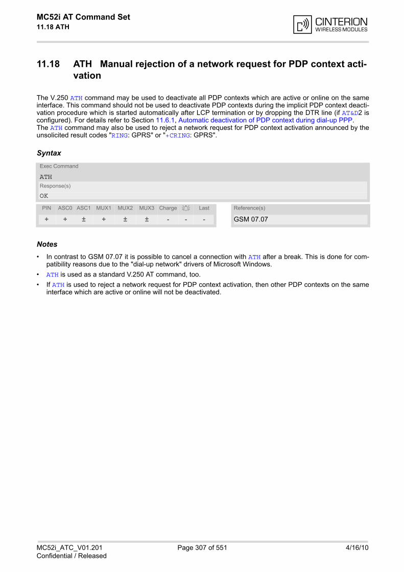
MC52i AT Command Set 11.18 ATH
MC52i_ATC_V01.201 Page 307 of 551 4/16/10Confidential / Released
11.18 ATH Manual rejection of a network request for PDP context acti-vation
The V.250 ATH command may be used to deactivate all PDP contexts which are active or online on the sameinterface. This command should not be used to deactivate PDP contexts during the implicit PDP context deacti-vation procedure which is started automatically after LCP termination or by dropping the DTR line (if AT&D2 isconfigured). For details refer to Section 11.6.1, Automatic deactivation of PDP context during dial-up PPP. The ATH command may also be used to reject a network request for PDP context activation announced by theunsolicited result codes "RING: GPRS" or "+CRING: GPRS".
Syntax
Notes• In contrast to GSM 07.07 it is possible to cancel a connection with ATH after a break. This is done for com-
patibility reasons due to the "dial-up network" drivers of Microsoft Windows.
• ATH is used as a standard V.250 AT command, too.
• If ATH is used to reject a network request for PDP context activation, then other PDP contexts on the sameinterface which are active or online will not be deactivated.
Exec Command
ATHResponse(s)
OK
PIN ASC0 ASC1 MUX1 MUX2 MUX3 Charge Last Reference(s)
+ + ± + ± ± - - - GSM 07.07
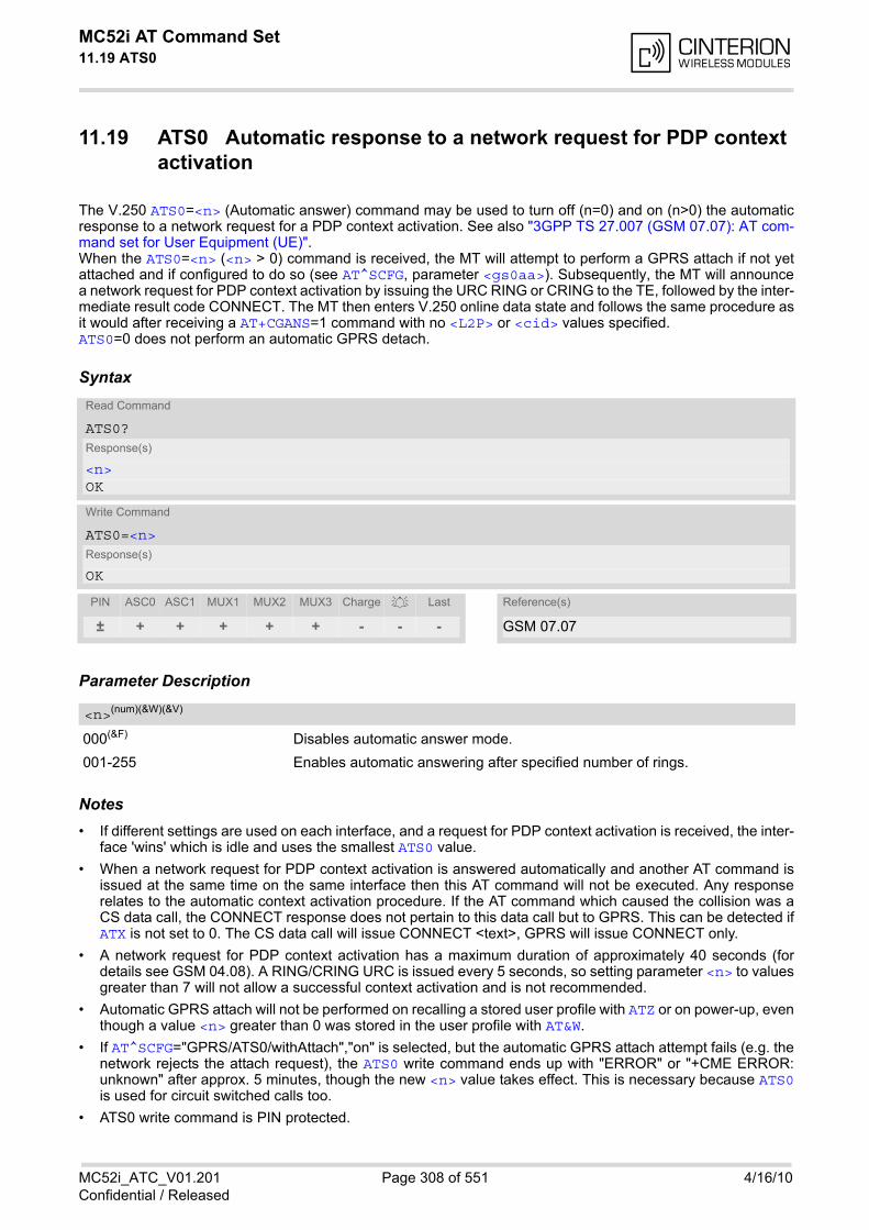
MC52i AT Command Set 11.19 ATS0
MC52i_ATC_V01.201 Page 308 of 551 4/16/10Confidential / Released
11.19 ATS0 Automatic response to a network request for PDP context activation
The V.250 ATS0=<n> (Automatic answer) command may be used to turn off (n=0) and on (n>0) the automaticresponse to a network request for a PDP context activation. See also "3GPP TS 27.007 (GSM 07.07): AT com-mand set for User Equipment (UE)". When the ATS0=<n> (<n> > 0) command is received, the MT will attempt to perform a GPRS attach if not yetattached and if configured to do so (see AT^SCFG, parameter <gs0aa>). Subsequently, the MT will announcea network request for PDP context activation by issuing the URC RING or CRING to the TE, followed by the inter-mediate result code CONNECT. The MT then enters V.250 online data state and follows the same procedure asit would after receiving a AT+CGANS=1 command with no <L2P> or <cid> values specified.ATS0=0 does not perform an automatic GPRS detach.
Syntax
Parameter Description
000(&F) Disables automatic answer mode.
001-255 Enables automatic answering after specified number of rings.
Notes• If different settings are used on each interface, and a request for PDP context activation is received, the inter-
face 'wins' which is idle and uses the smallest ATS0 value.
• When a network request for PDP context activation is answered automatically and another AT command isissued at the same time on the same interface then this AT command will not be executed. Any responserelates to the automatic context activation procedure. If the AT command which caused the collision was aCS data call, the CONNECT response does not pertain to this data call but to GPRS. This can be detected ifATX is not set to 0. The CS data call will issue CONNECT <text>, GPRS will issue CONNECT only.
• A network request for PDP context activation has a maximum duration of approximately 40 seconds (fordetails see GSM 04.08). A RING/CRING URC is issued every 5 seconds, so setting parameter <n> to valuesgreater than 7 will not allow a successful context activation and is not recommended.
• Automatic GPRS attach will not be performed on recalling a stored user profile with ATZ or on power-up, eventhough a value <n> greater than 0 was stored in the user profile with AT&W.
• If AT^SCFG="GPRS/ATS0/withAttach","on" is selected, but the automatic GPRS attach attempt fails (e.g. thenetwork rejects the attach request), the ATS0 write command ends up with "ERROR" or "+CME ERROR:unknown" after approx. 5 minutes, though the new <n> value takes effect. This is necessary because ATS0is used for circuit switched calls too.
• ATS0 write command is PIN protected.
Read Command
ATS0?Response(s)
<n>OK
Write Command
ATS0=<n>Response(s)
OK
PIN ASC0 ASC1 MUX1 MUX2 MUX3 Charge Last Reference(s)
± + + + + + - - - GSM 07.07
<n>(num)(&W)(&V)
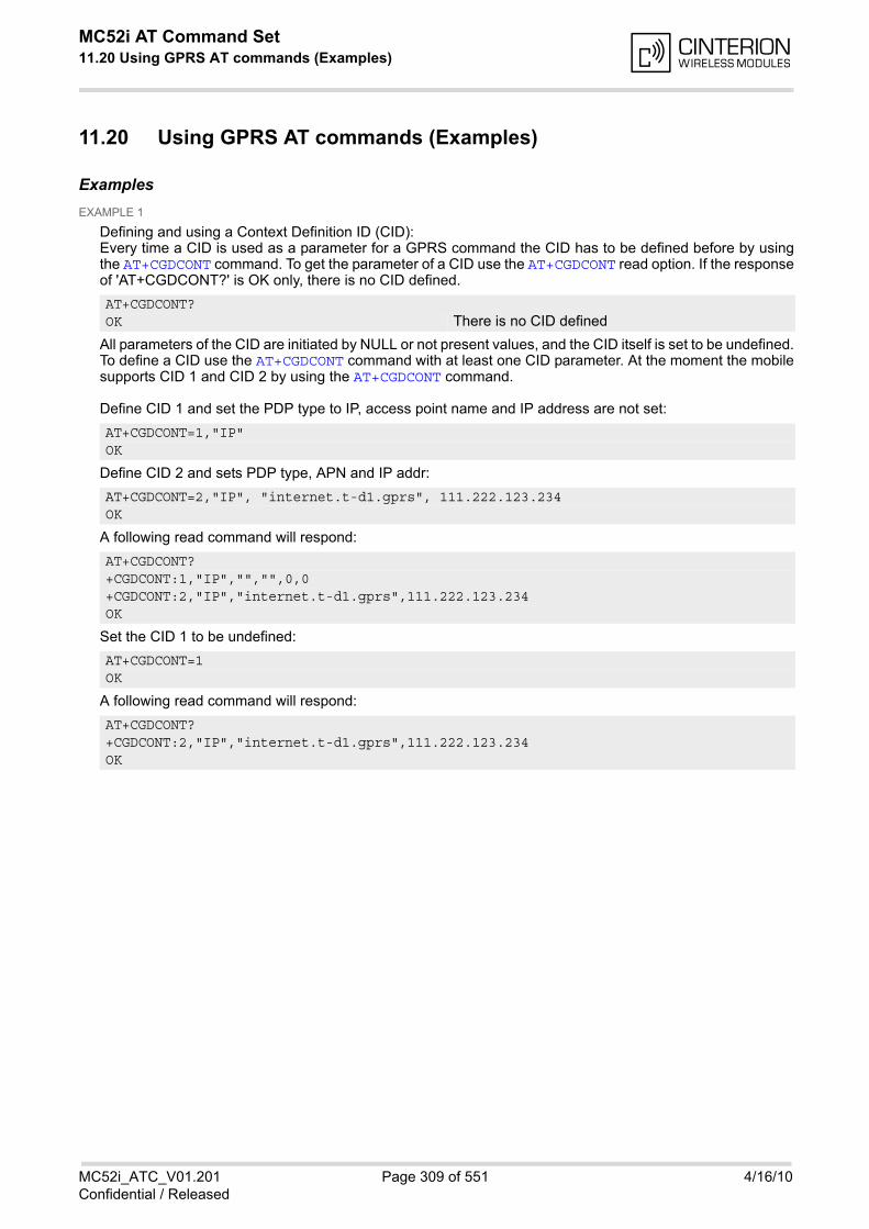
MC52i AT Command Set 11.20 Using GPRS AT commands (Examples)
MC52i_ATC_V01.201 Page 309 of 551 4/16/10Confidential / Released
11.20 Using GPRS AT commands (Examples)
ExamplesEXAMPLE 1
Defining and using a Context Definition ID (CID): Every time a CID is used as a parameter for a GPRS command the CID has to be defined before by usingthe AT+CGDCONT command. To get the parameter of a CID use the AT+CGDCONT read option. If the responseof 'AT+CGDCONT?' is OK only, there is no CID defined.
All parameters of the CID are initiated by NULL or not present values, and the CID itself is set to be undefined.To define a CID use the AT+CGDCONT command with at least one CID parameter. At the moment the mobilesupports CID 1 and CID 2 by using the AT+CGDCONT command.
Define CID 1 and set the PDP type to IP, access point name and IP address are not set:
Define CID 2 and sets PDP type, APN and IP addr:
A following read command will respond:
Set the CID 1 to be undefined:
A following read command will respond:
AT+CGDCONT?OK There is no CID defined
AT+CGDCONT=1,"IP"OK
AT+CGDCONT=2,"IP", "internet.t-d1.gprs", 111.222.123.234OK
AT+CGDCONT?+CGDCONT:1,"IP","","",0,0+CGDCONT:2,"IP","internet.t-d1.gprs",111.222.123.234OK
AT+CGDCONT=1OK
AT+CGDCONT?+CGDCONT:2,"IP","internet.t-d1.gprs",111.222.123.234OK
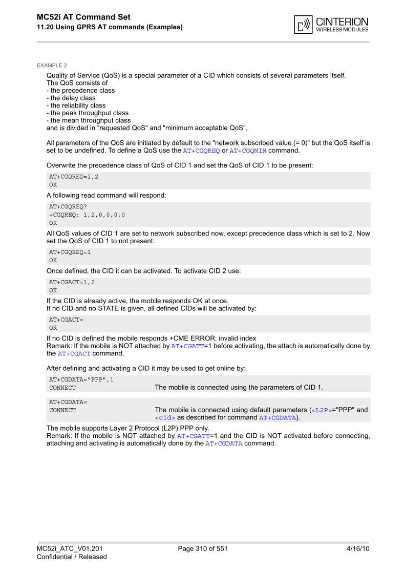
MC52i AT Command Set 11.20 Using GPRS AT commands (Examples)
MC52i_ATC_V01.201 Page 310 of 551 4/16/10Confidential / Released
EXAMPLE 2
Quality of Service (QoS) is a special parameter of a CID which consists of several parameters itself.The QoS consists of - the precedence class- the delay class- the reliability class- the peak throughput class- the mean throughput classand is divided in "requested QoS" and "minimum acceptable QoS".
All parameters of the QoS are initiated by default to the "network subscribed value (= 0)" but the QoS itself isset to be undefined. To define a QoS use the AT+CGQREQ or AT+CGQMIN command.
Overwrite the precedence class of QoS of CID 1 and set the QoS of CID 1 to be present:
A following read command will respond:
All QoS values of CID 1 are set to network subscribed now, except precedence class which is set to 2. Nowset the QoS of CID 1 to not present:
Once defined, the CID it can be activated. To activate CID 2 use:
If the CID is already active, the mobile responds OK at once.If no CID and no STATE is given, all defined CIDs will be activated by:
If no CID is defined the mobile responds +CME ERROR: invalid indexRemark: If the mobile is NOT attached by AT+CGATT=1 before activating, the attach is automatically done bythe AT+CGACT command.
After defining and activating a CID it may be used to get online by:
The mobile supports Layer 2 Protocol (L2P) PPP only.Remark: If the mobile is NOT attached by AT+CGATT=1 and the CID is NOT activated before connecting,attaching and activating is automatically done by the AT+CGDATA command.
AT+CGQREQ=1,2OK
AT+CGQREQ?+CGQREQ: 1,2,0,0,0,0OK
AT+CGQREQ=1OK
AT+CGACT=1,2OK
AT+CGACT=OK
AT+CGDATA="PPP",1CONNECT The mobile is connected using the parameters of CID 1.
AT+CGDATA=CONNECT The mobile is connected using default parameters (<L2P>="PPP" and
<cid> as described for command AT+CGDATA).

MC52i AT Command Set 11.21 Using the GPRS dial command ATD
MC52i_ATC_V01.201 Page 311 of 551 4/16/10Confidential / Released
11.21 Using the GPRS dial command ATD
Example
In addition to the GPRS AT commands you can use the "D" command to dial into to the GPRS network.
There are two GPRS Service Codes for the ATD command: Values 98 and 99.Examples:
ATD*99#CONNECT Establish a connection by service code 99.
ATD*99*123.124.125.126*PPP*1#CONNECT Establish a connection by service code 99, IP
address 123 and L2P = PPP and using CID 1.The CID has to be defined by AT+CGDCONT.
ATD*99**PPP#CONNECT Establish a connection by service code 99 and L2P
= PPP.
ATD*99***1#CONNECT Establish a connection by service code 99 and using
CID 1.
ATD*99**PPP*1#CONNECT Establish a connection by service code 99 and L2P
= PPP and using CID 1. The CID has to be definedby AT+CGDCONT.
ATD*98#CONNECT Establish a connection by service code 98.
ATD*98*1#CONNECT Establish an IP connection by service code 98 using
CID 1. The CID has to be defined by AT+CGDCONT.
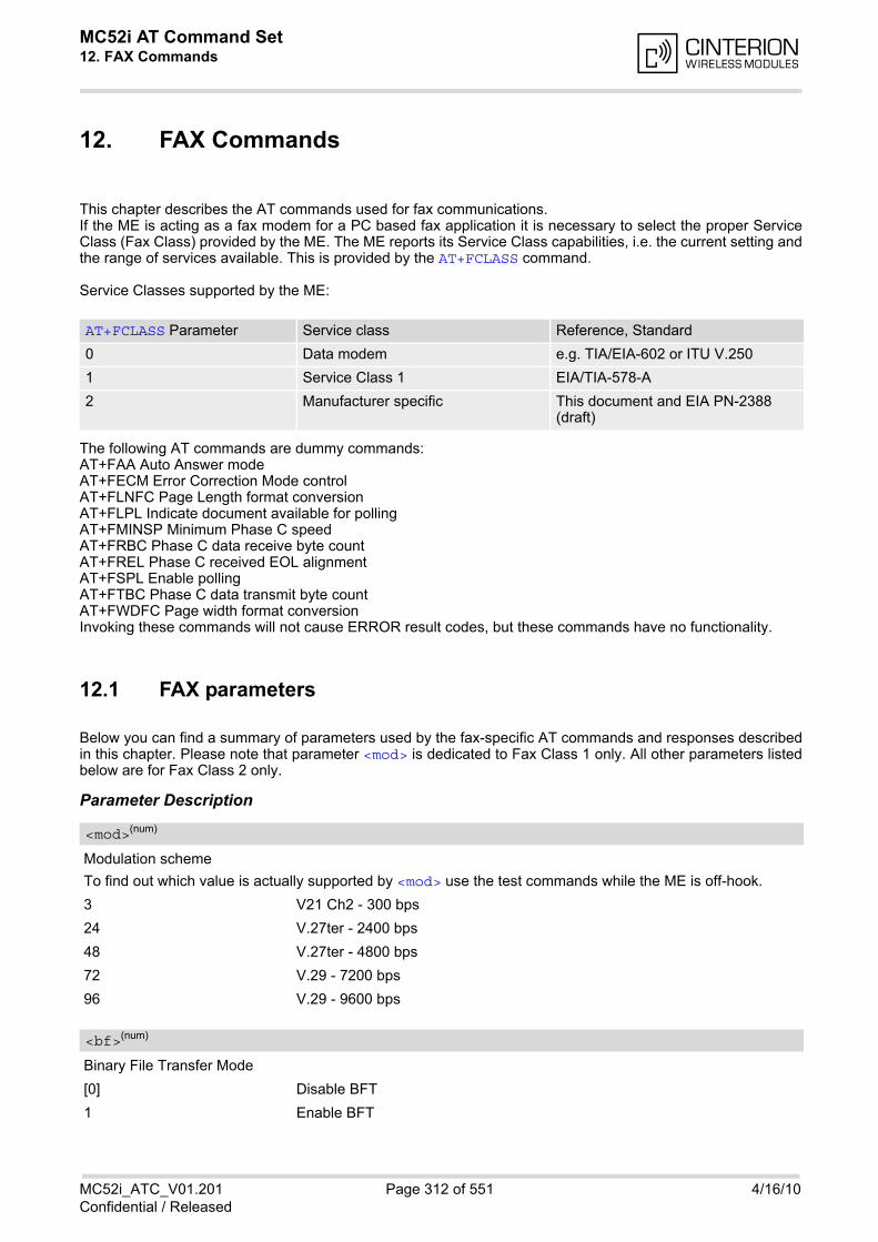
MC52i AT Command Set 12. FAX Commands
MC52i_ATC_V01.201 Page 312 of 551 4/16/10Confidential / Released
12. FAX Commands
This chapter describes the AT commands used for fax communications. If the ME is acting as a fax modem for a PC based fax application it is necessary to select the proper ServiceClass (Fax Class) provided by the ME. The ME reports its Service Class capabilities, i.e. the current setting andthe range of services available. This is provided by the AT+FCLASS command.
Service Classes supported by the ME:
The following AT commands are dummy commands: AT+FAA Auto Answer modeAT+FECM Error Correction Mode controlAT+FLNFC Page Length format conversionAT+FLPL Indicate document available for pollingAT+FMINSP Minimum Phase C speedAT+FRBC Phase C data receive byte countAT+FREL Phase C received EOL alignmentAT+FSPL Enable pollingAT+FTBC Phase C data transmit byte countAT+FWDFC Page width format conversionInvoking these commands will not cause ERROR result codes, but these commands have no functionality.
12.1 FAX parameters
Below you can find a summary of parameters used by the fax-specific AT commands and responses describedin this chapter. Please note that parameter <mod> is dedicated to Fax Class 1 only. All other parameters listedbelow are for Fax Class 2 only.
Parameter Description
Modulation scheme
To find out which value is actually supported by <mod> use the test commands while the ME is off-hook.
3 V21 Ch2 - 300 bps
24 V.27ter - 2400 bps
48 V.27ter - 4800 bps
72 V.29 - 7200 bps
96 V.29 - 9600 bps
Binary File Transfer Mode
[0] Disable BFT
1 Enable BFT
AT+FCLASS Parameter Service class Reference, Standard
0 Data modem e.g. TIA/EIA-602 or ITU V.250
1 Service Class 1 EIA/TIA-578-A
2 Manufacturer specific This document and EIA PN-2388 (draft)
<mod>(num)
<bf>(num)
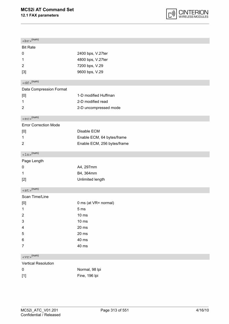
MC52i AT Command Set 12.1 FAX parameters
MC52i_ATC_V01.201 Page 313 of 551 4/16/10Confidential / Released
Bit Rate
0 2400 bps, V.27ter
1 4800 bps, V.27ter
2 7200 bps, V.29
[3] 9600 bps, V.29
Data Compression Format
[0] 1-D modified Huffman
1 2-D modified read
2 2-D uncompressed mode
Error Correction Mode
[0] Disable ECM
1 Enable ECM, 64 bytes/frame
2 Enable ECM, 256 bytes/frame
Page Length
0 A4, 297mm
1 B4, 364mm
[2] Unlimited length
Scan Time/Line
[0] 0 ms (at VR= normal)
1 5 ms
2 10 ms
3 10 ms
4 20 ms
5 20 ms
6 40 ms
7 40 ms
Vertical Resolution
0 Normal, 98 lpi
[1] Fine, 196 lpi
<br>(num)
<df>(num)
<ec>(num)
<ln>(num)
<st>(num)
<vr>(num)

MC52i AT Command Set 12.1 FAX parameters
MC52i_ATC_V01.201 Page 314 of 551 4/16/10Confidential / Released
Page Width
[0] 1728 pixels in 215mm
1 2048 pixels in 255 mm
2 2432 pixels in 303 mm
3 1216 pixels in 151 mm
4 864 pixels in 107 mm
Note• The host application is not required to support all values of the parameters listed above. Depending on the
application design it may be sufficient to implement only the default values. See T.31, T.32 and EIA PN-2388specifications for further advice.
12.1.1 Summary of Fax Class 2 URCs defined by EIA PN-2388
The following URCs are messages indicated in communication only. The URCs are not user definable.
Table 12.1: Summary of Fax Class 2 URCs defined by EIA PN-2388
<wd>(num)
URC Meaning
+FCON Indicates connection with a fax machine.
+FCSI: <id> Reports the remote ID, called station ID.
+FDCS: <vr>, <br>, <wd>, <ln>, <df>, <ec>, <bf>, <st>
Reports current session parameters (refer to EIA PN-2388, Table 3.10).
+FDIS: <vr>, <br>, <wd>, <ln>, <df>, <ec>, <bf>, <st>
Reports the remote station capabilities (refer to EIA PN-2388, Table 3.10).
+FET: <stat> Post page message. Indicates whether or not further pages or documents are pending.
+FHNG: <stat> Reports that call has been terminated and indicates status.
+FNSF: "<param>" Reports non-standard setup frame.
+FPTS: "<stat>" Reports the status of received pages.
+FTSI: "<id>" Reports the remote ID, transmit station ID.
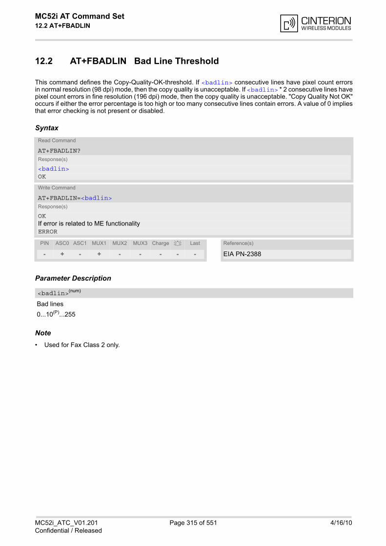
MC52i AT Command Set 12.2 AT+FBADLIN
MC52i_ATC_V01.201 Page 315 of 551 4/16/10Confidential / Released
12.2 AT+FBADLIN Bad Line Threshold
This command defines the Copy-Quality-OK-threshold. If <badlin> consecutive lines have pixel count errorsin normal resolution (98 dpi) mode, then the copy quality is unacceptable. If <badlin> * 2 consecutive lines havepixel count errors in fine resolution (196 dpi) mode, then the copy quality is unacceptable. "Copy Quality Not OK"occurs if either the error percentage is too high or too many consecutive lines contain errors. A value of 0 impliesthat error checking is not present or disabled.
Syntax
Parameter Description
Bad lines
0...10(P)...255
Note• Used for Fax Class 2 only.
Read Command
AT+FBADLIN?Response(s)
<badlin>OK
Write Command
AT+FBADLIN=<badlin>Response(s)
OKIf error is related to ME functionalityERROR
PIN ASC0 ASC1 MUX1 MUX2 MUX3 Charge Last Reference(s)
- + - + - - - - - EIA PN-2388
<badlin>(num)
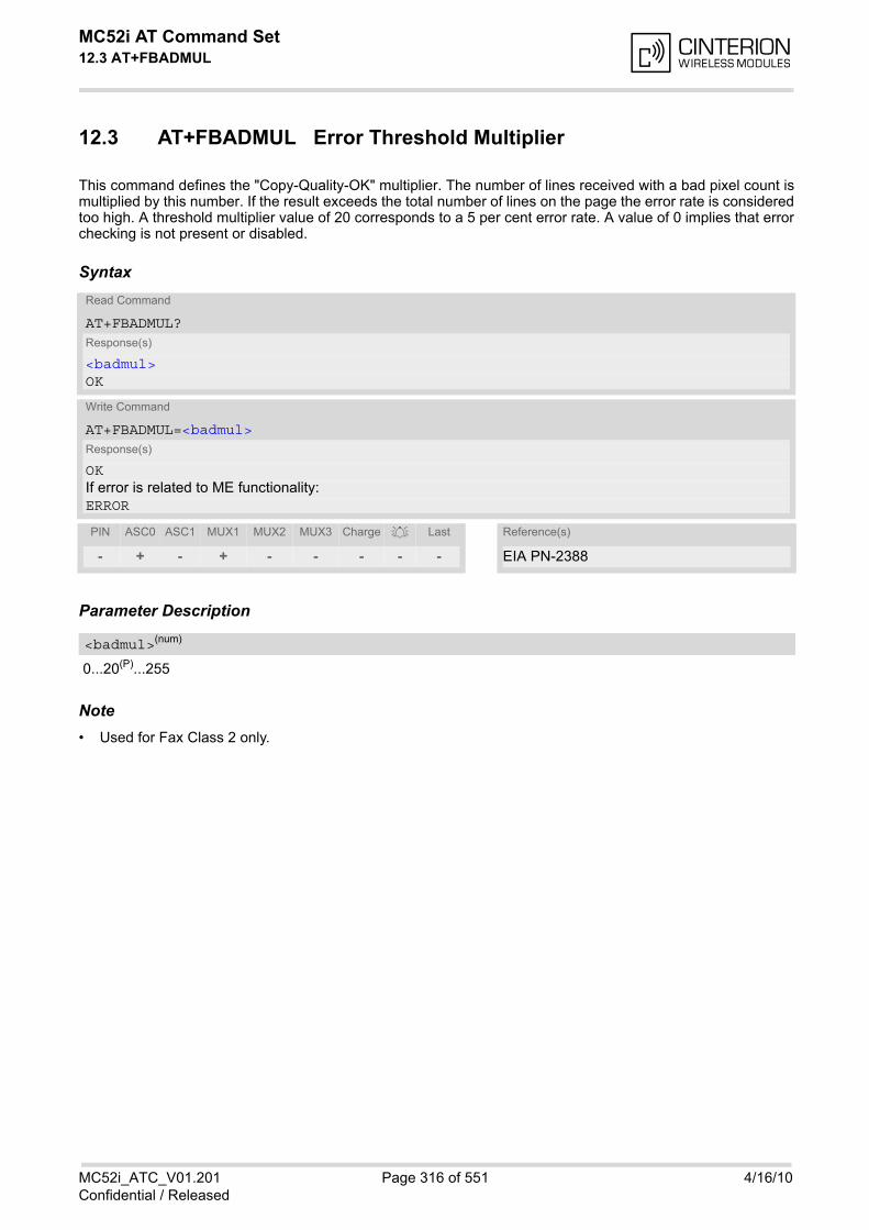
MC52i AT Command Set 12.3 AT+FBADMUL
MC52i_ATC_V01.201 Page 316 of 551 4/16/10Confidential / Released
12.3 AT+FBADMUL Error Threshold Multiplier
This command defines the "Copy-Quality-OK" multiplier. The number of lines received with a bad pixel count ismultiplied by this number. If the result exceeds the total number of lines on the page the error rate is consideredtoo high. A threshold multiplier value of 20 corresponds to a 5 per cent error rate. A value of 0 implies that errorchecking is not present or disabled.
Syntax
Parameter Description
0...20(P)...255
Note• Used for Fax Class 2 only.
Read Command
AT+FBADMUL?Response(s)
<badmul>OK
Write Command
AT+FBADMUL=<badmul>Response(s)
OKIf error is related to ME functionality:ERROR
PIN ASC0 ASC1 MUX1 MUX2 MUX3 Charge Last Reference(s)
- + - + - - - - - EIA PN-2388
<badmul>(num)
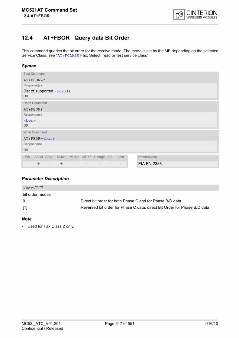
MC52i AT Command Set 12.4 AT+FBOR
MC52i_ATC_V01.201 Page 317 of 551 4/16/10Confidential / Released
12.4 AT+FBOR Query data Bit Order
This command queries the bit order for the receive mode. The mode is set by the ME depending on the selectedService Class, see "AT+FCLASS Fax: Select, read or test service class".
Syntax
Parameter Description
bit order modes
0 Direct bit order for both Phase C and for Phase B/D data.
[1] Reversed bit order for Phase C data, direct Bit Order for Phase B/D data.
Note• Used for Fax Class 2 only.
Test Command
AT+FBOR=?Response(s)
(list of supported <bor>s)OK
Read Command
AT+FBOR?Response(s)
<bor>OK
Write Command
AT+FBOR=<bor>Response(s)
OK
PIN ASC0 ASC1 MUX1 MUX2 MUX3 Charge Last Reference(s)
- + - + - - - - - EIA PN-2388
<bor>(num)
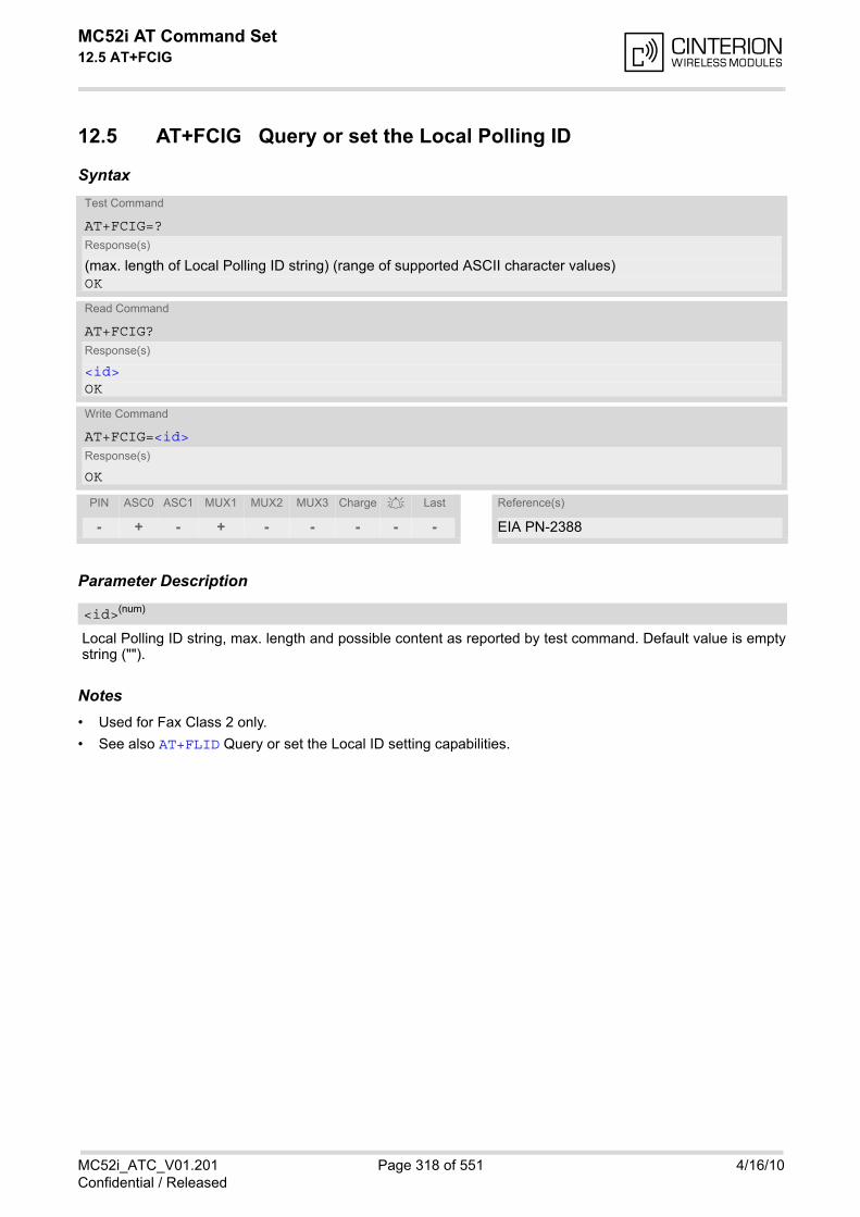
MC52i AT Command Set 12.5 AT+FCIG
MC52i_ATC_V01.201 Page 318 of 551 4/16/10Confidential / Released
12.5 AT+FCIG Query or set the Local Polling ID
Syntax
Parameter Description
Local Polling ID string, max. length and possible content as reported by test command. Default value is emptystring ("").
Notes• Used for Fax Class 2 only.
• See also AT+FLID Query or set the Local ID setting capabilities.
Test Command
AT+FCIG=?Response(s)
(max. length of Local Polling ID string) (range of supported ASCII character values) OK
Read Command
AT+FCIG?Response(s)
<id>OK
Write Command
AT+FCIG=<id>Response(s)
OK
PIN ASC0 ASC1 MUX1 MUX2 MUX3 Charge Last Reference(s)
- + - + - - - - - EIA PN-2388
<id>(num)
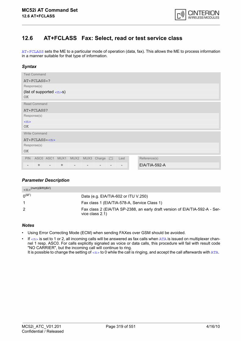
MC52i AT Command Set 12.6 AT+FCLASS
MC52i_ATC_V01.201 Page 319 of 551 4/16/10Confidential / Released
12.6 AT+FCLASS Fax: Select, read or test service class
AT+FCLASS sets the ME to a particular mode of operation (data, fax). This allows the ME to process informationin a manner suitable for that type of information.
Syntax
Parameter Description
0(&F) Data (e.g. EIA/TIA-602 or ITU V.250)
1 Fax class 1 (EIA/TIA-578-A, Service Class 1)
2 Fax class 2 (EIA/TIA SP-2388, an early draft version of EIA/TIA-592-A - Ser-vice class 2.1)
Notes• Using Error Correcting Mode (ECM) when sending FAXes over GSM should be avoided.
• If <n> is set to 1 or 2, all incoming calls will be answered as fax calls when ATA is issued on multiplexer chan-nel 1 resp. ASC0. For calls explicitly signaled as voice or data calls, this procedure will fail with result code"NO CARRIER", but the incoming call will continue to ring.It is possible to change the setting of <n> to 0 while the call is ringing, and accept the call afterwards with ATA.
Test Command
AT+FCLASS=?Response(s)
(list of supported <n>s)OK
Read Command
AT+FCLASS?Response(s)
<n>OK
Write Command
AT+FCLASS=<n>Response(s)
OK
PIN ASC0 ASC1 MUX1 MUX2 MUX3 Charge Last Reference(s)
- + - + - - - - - EIA/TIA-592-A
<n>(num)(&W)(&V)

MC52i AT Command Set 12.7 AT+FCQ
MC52i_ATC_V01.201 Page 320 of 551 4/16/10Confidential / Released
12.7 AT+FCQ Copy Quality Checking
This command controls Copy Quality checking when receiving a fax.
Syntax
Parameter Description
0 No copy quality checking. The ME will generate Copy Quality OK (MCF)responses to complete pages.
[1] ME can check 1-D phase data. The connected application must check copyquality for 2-D phase C data.
Note• Used for Fax Class 2 only.
Test Command
AT+FCQ=?Response(s)
(list of supported copy quality checking <cq>s)OK
Read Command
AT+FCQ?Response(s)
<cq>OK
Write Command
AT+FCQ=<cq>Response(s)
OK
PIN ASC0 ASC1 MUX1 MUX2 MUX3 Charge Last Reference(s)
- + - + - - - - - EIA PN-2388
<cq>(num)
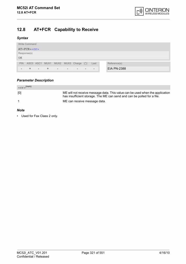
MC52i AT Command Set 12.8 AT+FCR
MC52i_ATC_V01.201 Page 321 of 551 4/16/10Confidential / Released
12.8 AT+FCR Capability to Receive
Syntax
Parameter Description
[0] ME will not receive message data. This value can be used when the applicationhas insufficient storage. The ME can send and can be polled for a file.
1 ME can receive message data.
Note• Used for Fax Class 2 only.
Write Command
AT+FCR=<cr>Response(s)
OK
PIN ASC0 ASC1 MUX1 MUX2 MUX3 Charge Last Reference(s)
- + - + - - - - - EIA PN-2388
<cr>(num)
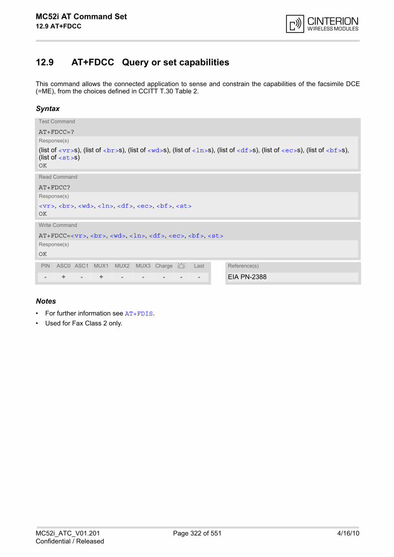
MC52i AT Command Set 12.9 AT+FDCC
MC52i_ATC_V01.201 Page 322 of 551 4/16/10Confidential / Released
12.9 AT+FDCC Query or set capabilities
This command allows the connected application to sense and constrain the capabilities of the facsimile DCE(=ME), from the choices defined in CCITT T.30 Table 2.
Syntax
Notes• For further information see AT+FDIS.
• Used for Fax Class 2 only.
Test Command
AT+FDCC=?Response(s)
(list of <vr>s), (list of <br>s), (list of <wd>s), (list of <ln>s), (list of <df>s), (list of <ec>s), (list of <bf>s), (list of <st>s)OK
Read Command
AT+FDCC?Response(s)
<vr>, <br>, <wd>, <ln>, <df>, <ec>, <bf>, <st>OK
Write Command
AT+FDCC=<vr>, <br>, <wd>, <ln>, <df>, <ec>, <bf>, <st>Response(s)
OK
PIN ASC0 ASC1 MUX1 MUX2 MUX3 Charge Last Reference(s)
- + - + - - - - - EIA PN-2388
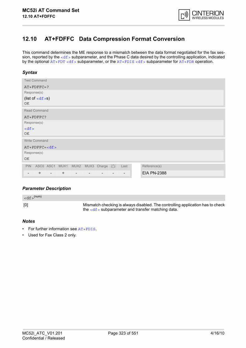
MC52i AT Command Set 12.10 AT+FDFFC
MC52i_ATC_V01.201 Page 323 of 551 4/16/10Confidential / Released
12.10 AT+FDFFC Data Compression Format Conversion
This command determines the ME response to a mismatch between the data format negotiated for the fax ses-sion, reported by the <df> subparameter, and the Phase C data desired by the controlling application, indicatedby the optional AT+FDT <df> subparameter, or the AT+FDIS <df> subparameter for AT+FDR operation.
Syntax
Parameter Description
[0] Mismatch checking is always disabled. The controlling application has to checkthe <df> subparameter and transfer matching data.
Notes• For further information see AT+FDIS.
• Used for Fax Class 2 only.
Test Command
AT+FDFFC=?Response(s)
(list of <df>s)OK
Read Command
AT+FDFFC?Response(s)
<df>OK
Write Command
AT+FDFFC=<df>Response(s)
OK
PIN ASC0 ASC1 MUX1 MUX2 MUX3 Charge Last Reference(s)
- + - + - - - - - EIA PN-2388
<df>(num)
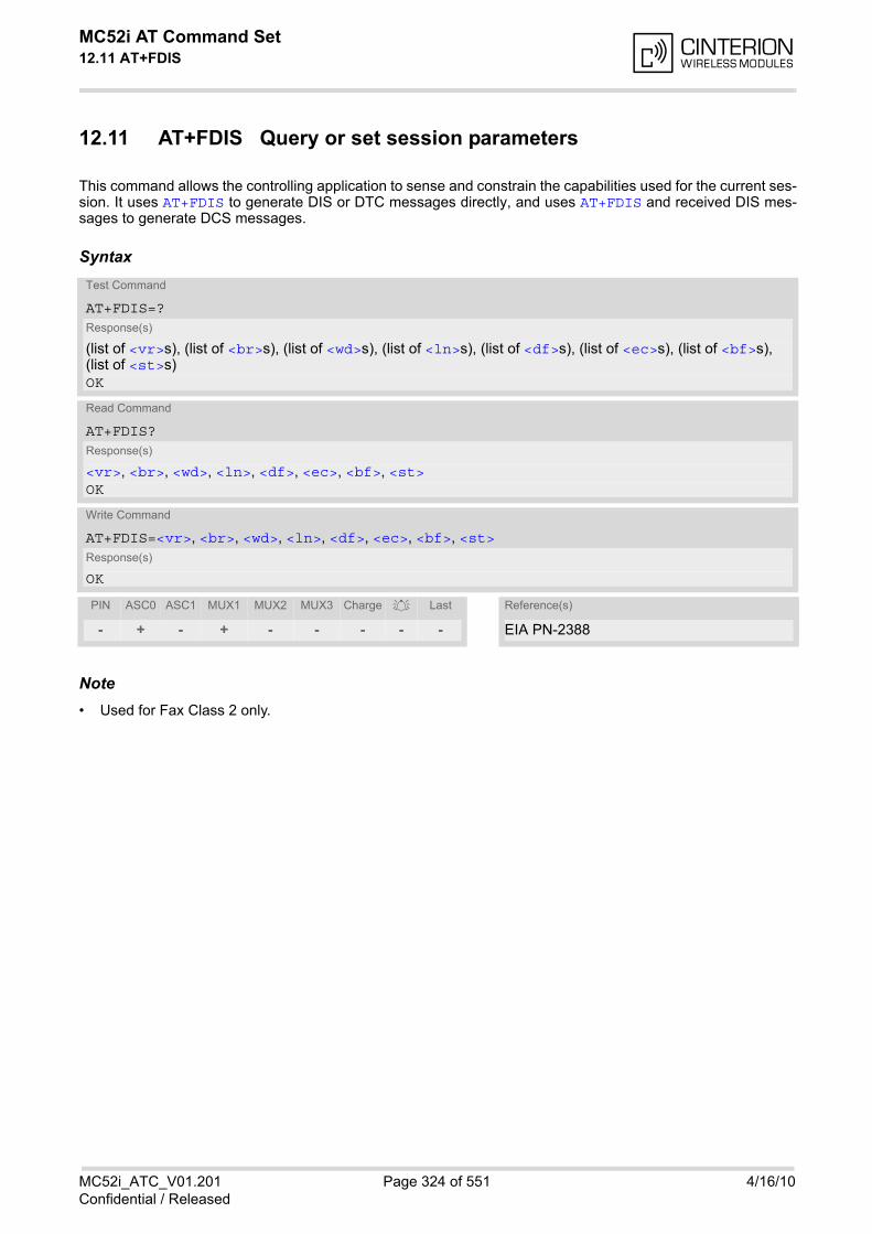
MC52i AT Command Set 12.11 AT+FDIS
MC52i_ATC_V01.201 Page 324 of 551 4/16/10Confidential / Released
12.11 AT+FDIS Query or set session parameters
This command allows the controlling application to sense and constrain the capabilities used for the current ses-sion. It uses AT+FDIS to generate DIS or DTC messages directly, and uses AT+FDIS and received DIS mes-sages to generate DCS messages.
Syntax
Note• Used for Fax Class 2 only.
Test Command
AT+FDIS=?Response(s)
(list of <vr>s), (list of <br>s), (list of <wd>s), (list of <ln>s), (list of <df>s), (list of <ec>s), (list of <bf>s), (list of <st>s)OK
Read Command
AT+FDIS?Response(s)
<vr>, <br>, <wd>, <ln>, <df>, <ec>, <bf>, <st>OK
Write Command
AT+FDIS=<vr>, <br>, <wd>, <ln>, <df>, <ec>, <bf>, <st>Response(s)
OK
PIN ASC0 ASC1 MUX1 MUX2 MUX3 Charge Last Reference(s)
- + - + - - - - - EIA PN-2388
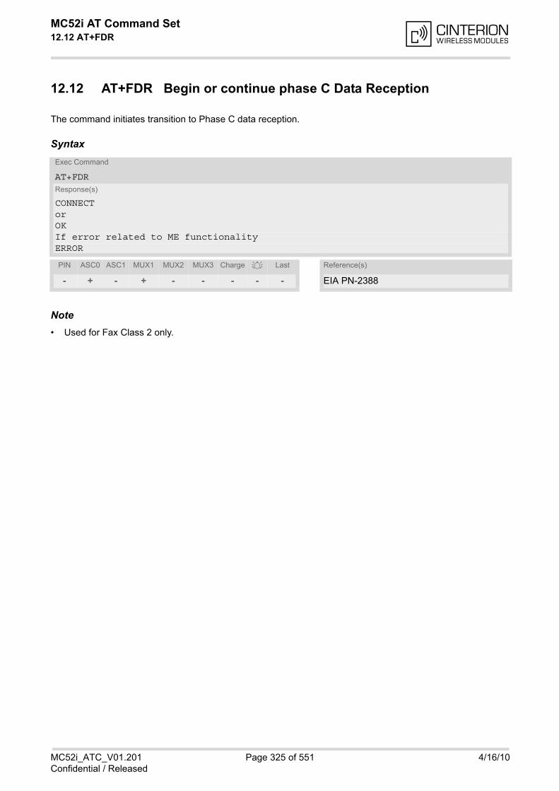
MC52i AT Command Set 12.12 AT+FDR
MC52i_ATC_V01.201 Page 325 of 551 4/16/10Confidential / Released
12.12 AT+FDR Begin or continue phase C Data Reception
The command initiates transition to Phase C data reception.
Syntax
Note• Used for Fax Class 2 only.
Exec Command
AT+FDRResponse(s)
CONNECTorOKIf error related to ME functionalityERROR
PIN ASC0 ASC1 MUX1 MUX2 MUX3 Charge Last Reference(s)
- + - + - - - - - EIA PN-2388
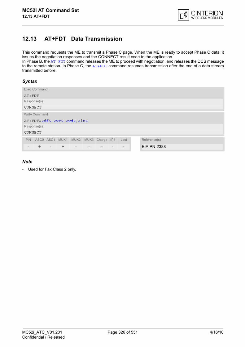
MC52i AT Command Set 12.13 AT+FDT
MC52i_ATC_V01.201 Page 326 of 551 4/16/10Confidential / Released
12.13 AT+FDT Data Transmission
This command requests the ME to transmit a Phase C page. When the ME is ready to accept Phase C data, itissues the negotiation responses and the CONNECT result code to the application. In Phase B, the AT+FDT command releases the ME to proceed with negotiation, and releases the DCS messageto the remote station. In Phase C, the AT+FDT command resumes transmission after the end of a data streamtransmitted before.
Syntax
Note• Used for Fax Class 2 only.
Exec Command
AT+FDTResponse(s)
CONNECT
Write Command
AT+FDT=<df>, <vr>, <wd>, <ln>Response(s)
CONNECT
PIN ASC0 ASC1 MUX1 MUX2 MUX3 Charge Last Reference(s)
- + - + - - - - - EIA PN-2388
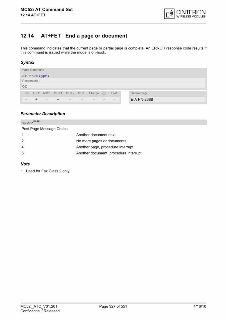
MC52i AT Command Set 12.14 AT+FET
MC52i_ATC_V01.201 Page 327 of 551 4/16/10Confidential / Released
12.14 AT+FET End a page or document
This command indicates that the current page or partial page is complete. An ERROR response code results ifthis command is issued while the mode is on-hook.
Syntax
Parameter Description
Post Page Message Codes
1 Another document next
2 No more pages or documents
4 Another page, procedure interrupt
5 Another document, procedure interrupt
Note• Used for Fax Class 2 only.
Write Command
AT+FET=<ppm>Response(s)
OK
PIN ASC0 ASC1 MUX1 MUX2 MUX3 Charge Last Reference(s)
- + - + - - - - - EIA PN-2388
<ppm>(num)
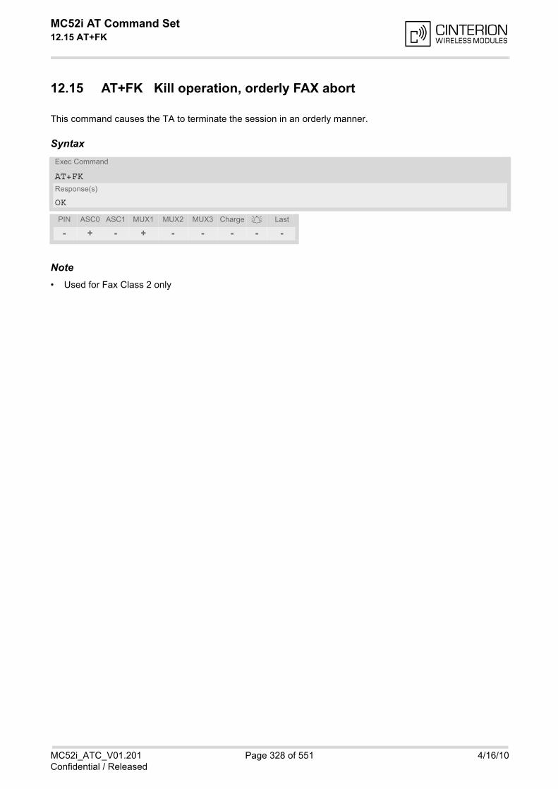
MC52i AT Command Set 12.15 AT+FK
MC52i_ATC_V01.201 Page 328 of 551 4/16/10Confidential / Released
12.15 AT+FK Kill operation, orderly FAX abort
This command causes the TA to terminate the session in an orderly manner.
Syntax
Note• Used for Fax Class 2 only
Exec Command
AT+FKResponse(s)
OK
PIN ASC0 ASC1 MUX1 MUX2 MUX3 Charge Last
- + - + - - - - -

MC52i AT Command Set 12.16 AT+FLID
MC52i_ATC_V01.201 Page 329 of 551 4/16/10Confidential / Released
12.16 AT+FLID Query or set the Local Id setting capabilities
Syntax
Parameter Description
Local ID string
Max. length and possible content as reported by test command. Default value is empty string ("").
Notes• Used for Fax Class 2 only.
• See also AT+FCIG.
Test Command
AT+FLID=?Response(s)
(max. character length of Local ID string) (range of supported ASCII character values) OK
Read Command
AT+FLID?Response(s)
<lid>OK
Write Command
AT+FLID=<lid>Response(s)
OK
PIN ASC0 ASC1 MUX1 MUX2 MUX3 Charge Last Reference(s)
- + - + - - - - - EIA PN-2388
<lid>(num)

MC52i AT Command Set 12.17 AT+FMDL
MC52i_ATC_V01.201 Page 330 of 551 4/16/10Confidential / Released
12.17 AT+FMDL Identify Product Model
This command sends the model identification to the TA.
Syntax
Note• Used for Fax Class 2 only.
Read Command
AT+FMDL?Response(s)
Gipsy Soft ProtocolstackOK
PIN ASC0 ASC1 MUX1 MUX2 MUX3 Charge Last
- + - + - - - - -
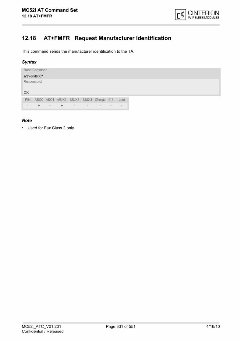
MC52i AT Command Set 12.18 AT+FMFR
MC52i_ATC_V01.201 Page 331 of 551 4/16/10Confidential / Released
12.18 AT+FMFR Request Manufacturer Identification
This command sends the manufacturer identification to the TA.
Syntax
Note• Used for Fax Class 2 only
Read Command
AT+FMFR?Response(s)
OK
PIN ASC0 ASC1 MUX1 MUX2 MUX3 Charge Last
- + - + - - - - -
MC52i AT Command Set 12.19 AT+FOPT
MC52i_ATC_V01.201 Page 332 of 551 4/16/10Confidential / Released
12.19 AT+FOPT Set bit Order independently
Model specific command to set bit order independently of the understanding which is "mirrored" and which isdirect.
Syntax
Parameter Description
0 Non-standard
1 Standard
Note• Used for Fax Class 2 only.
Write Command
AT+FOPT=<opt>Response(s)
OK
PIN ASC0 ASC1 MUX1 MUX2 MUX3 Charge Last
- + - + - - - - -
<opt>(num)
MC52i AT Command Set 12.20 AT+FPHCTO
MC52i_ATC_V01.201 Page 333 of 551 4/16/10Confidential / Released
12.20 AT+FPHCTO DTE Phase C Response Timeout
The timeout value <tout> determines how long the DCE will wait for a command after reaching the end of datawhen transmitting in Phase C. When timeout is reached, the DCE assumes that there are no more pages or doc-uments to send.
Syntax
Parameter Description
Timeout
Value in 100ms units
0...30(P)...255
Note• Used for Fax Class 2 only.
Read Command
AT+FPHCTO?Response(s)
<tout>OK
Write Command
AT+FPHCTO=<tout>Response(s)
OKIf error is related to ME functionalityERROR
PIN ASC0 ASC1 MUX1 MUX2 MUX3 Charge Last Reference(s)
- + - + - - - - - EIA PN-2388
<tout>(num)
MC52i AT Command Set 12.21 AT+FREV
MC52i_ATC_V01.201 Page 334 of 551 4/16/10Confidential / Released
12.21 AT+FREV Identify Product Revision
This comand sends the revision identification to the TA.
Syntax
Note• Used for Fax Class 2 only.
Read Command
AT+FREV?Response(s)
V2.550OK
PIN ASC0 ASC1 MUX1 MUX2 MUX3 Charge Last
- + - + - - - - -
MC52i AT Command Set 12.22 AT+FRH
MC52i_ATC_V01.201 Page 335 of 551 4/16/10Confidential / Released
12.22 AT+FRH Receive Data Using HDLC Framing
The AT+FRH command enables the TA to receive frames using the HDLC protocol and the modulation schemesdefined in Section 12.1, FAX parameters. An ERROR response code results if the command is issued while themodem is on-hook. The test command can be used in off-hook mode to check the modulation schemes sup-ported by MC52i.
Syntax
Note• Used for Fax Class 1 only.
Test Command
AT+FRH=?Response(s)
In off-hook mode only:+FRH:(list of <mod>s)OKIn on-hook mode:ERROR
Write Command
AT+FRH=<mod>Response(s)
CONNECTIf error is related to ME functionalityERROR
PIN ASC0 ASC1 MUX1 MUX2 MUX3 Charge Last Reference(s)
- + - + - - - - - TIA/EIA-578
MC52i AT Command Set 12.23 AT+FRM
MC52i_ATC_V01.201 Page 336 of 551 4/16/10Confidential / Released
12.23 AT+FRM Receive Data
The AT+FRM command causes the TA to enter the receive mode, using one of the modulation schemes definedin Section 12.1, FAX parameters.
An ERROR response code results if the write command is issued while the modem is on-hook. The test com-mand can be used in on-hook or off-hook mode to check the modulation schemes supported by MC52i.
Syntax
Notes• Used for Fax Class 1 only.
• <mod>= 3 is not possible.
Test Command
AT+FRM=?Response(s)
(list of <mod>s)OK
Write Command
AT+FRM=<mod>Response(s)
CONNECTIf error is related to ME functionality:ERROR
PIN ASC0 ASC1 MUX1 MUX2 MUX3 Charge Last Reference(s)
- + - + - - - - - TIA/EIA-578
MC52i AT Command Set 12.24 AT+FRS
MC52i_ATC_V01.201 Page 337 of 551 4/16/10Confidential / Released
12.24 AT+FRS Receive Silence
<time>=n causes the TA to report an OK result code to the TE after the specified period of silence was detectedon the line. The command is aborted if any character is received by the TE. The modem discards the aborting character andissues an OK result code. An ERROR response code results if this command is issued while the mode is on-hook.
Syntax
Parameter Description
Number of 10 millisecond intervals
0...255
Note• Used for Fax Class 1 only
Write Command
AT+FRS=<time>Response(s)
OKIf error is related to ME functionality:ERROR
PIN ASC0 ASC1 MUX1 MUX2 MUX3 Charge Last Reference(s)
- + - + - - - - - TIA/EIA-578
<time>(num)

MC52i AT Command Set 12.25 AT+FTH
MC52i_ATC_V01.201 Page 338 of 551 4/16/10Confidential / Released
12.25 AT+FTH Transmit Data Using HDLC Framing
The AT+FTH command causes the TA to transmit data using the HDLC protocol and the modulation schemesdefined in Section 12.1, FAX parameters. An ERROR response code results if the command is issued while themodem is on-hook. The test command can be used in off-hook mode to check the modulation schemes sup-ported by MC52i.
Syntax
Note• Used for Fax Class 1 only
Test Command
AT+FTH=?Response(s)
In off-hook mode only:+FTH:(list of <mod>s)OKIn on-hook mode:ERROR
Write Command
AT+FTH=<mod>Response(s)
CONNECT
PIN ASC0 ASC1 MUX1 MUX2 MUX3 Charge Last Reference(s)
- + - + - - - - - TIA/EIA-578
MC52i AT Command Set 12.26 AT+FTM
MC52i_ATC_V01.201 Page 339 of 551 4/16/10Confidential / Released
12.26 AT+FTM Transmit Data
The AT+FTM command causes the TA to transmit data, using one of the modulation schemes defined in Section12.1, FAX parameters.
An ERROR response code results if the write command is issued while the modem is on-hook. The test com-mand can be used in on-hook or off-hook mode to check the modulation schemes supported by MC52i.
Syntax
Notes• Used for Fax Class 1 only.
• <mod>= 3 is not possible
Test Command
AT+FTM=?Response(s)
(list of <mod>s)OK
Write Command
AT+FTM=<mod>Response(s)
CONNECTIf error is related to ME functionality:ERROR
PIN ASC0 ASC1 MUX1 MUX2 MUX3 Charge Last Reference(s)
- + - + - - - - - TIA/EIA-578
MC52i AT Command Set 12.27 AT+FTS
MC52i_ATC_V01.201 Page 340 of 551 4/16/10Confidential / Released
12.27 AT+FTS Stop Transmission and Wait
This command causes the TA to terminate a transmission and wait for <time> 10 millisecond intervals beforesending the OK result code to the TE.
Syntax
Parameter Description
no. of 10 millisecond intervals
0...85
Note• Used for Fax Class 1 only
Write Command
AT+FTS=<time>Response(s)
OKIn on-hook mode:ERROR
PIN ASC0 ASC1 MUX1 MUX2 MUX3 Charge Last Reference(s)
- + - + - - - - - TIA/EIA-578
<time>(num)
MC52i AT Command Set 12.28 AT+FVRFC
MC52i_ATC_V01.201 Page 341 of 551 4/16/10Confidential / Released
12.28 AT+FVRFC Vertical Resolution Format Conversion
This command determines the DCE response to a mismatch between the vertical resolution negotiated for thefacsimile session and the Phase C data desired by the DTE.
Syntax
Parameter Description
0 Disable mismatch checking.
[2] Enable mismatch checking, with resolution conversion of 1-D data in the DCE,and an implied AT+FK command executed on 2-D mismatch detection.
Note• Used for Fax Class 2 only.
Test Command
AT+FVRFC=?Response(s)
(list of supported <vrfc>s)OK
Read Command
AT+FVRFC?Response(s)
<vrfc>OK
Write Command
AT+FVRFC=<vrfc>Response(s)
OK
PIN ASC0 ASC1 MUX1 MUX2 MUX3 Charge Last Reference(s)
- + - + - - - - - EIA PN-2388
<vrfc>(num)
MC52i AT Command Set 13. Short Message Service (SMS) Commands
MC52i_ATC_V01.201 Page 342 of 551 4/16/10Confidential / Released
13. Short Message Service (SMS) Commands
The AT Commands described in this chapter allow an external application to use the Short Message Service withthe MC52i.
13.1 SMS parameters
Parameter Description
Format is same for <pdu> in case of SMS, but without GSM 24.11 SC address field and parameter shall bebounded by double quote characters like a normal string type parameter
String type alphanumeric representation of <da> or <oa> corresponding to the entry found in phonebook; thisfeature is not supported
Command Data
GSM 03.40 TP-Command-Data in text mode responses; ME/TA converts each 8-bit octet into two IRA characterlong hexadecimal numbers (e.g. octet with integer value 42 is presented to TE as two characters 2A (IRA 50and 65))
Command Type
GSM 03.40 TP-Command-Type in integer format
[0]...255
Destination Address
GSM 03.40 TP- Destination-Address Address-Value field in string format; BCD numbers (or GSM default alpha-bet characters) are converted into characters; type of address given by <toda>
User Data
In case of SMS: GSM 03.40 TP-User-Data in text mode responses; format:
• If <dcs> indicates that GSM 03.38 default alphabet is used and <fo> indicates that GSM 03.40 TP-User-Data-Header-Indication is not set: ME/TA converts GSM alphabet into current TE character set according torules covered in Annex A.
• If <dcs> indicates that 8-bit or UCS2 data coding scheme is used, or <fo> indicates that GSM 03.40 TP-User-Data-Header-Indication is set: ME/TA converts each 8-bit octet into hexadecimal numbers con-tainingtwo IRA characters (e.g. octet with integer value 42 is presented to TE as two characters 2A (IRA 50 and 65).
In case of CBS: GSM 03.41 CBM Content of Message in text mode responses; format:
• If <dcs> indicates that GSM 03.38 default alphabet is used: ME/TA converts GSM alphabet into current TEcharacter set according to rules covered in Annex A.
• If <dcs> indicates that 8-bit or UCS2 data coding scheme is used: ME/TA converts each 8-bit octet into hexa-decimal numbers containing two IRA characters.
<ackpdu>(num)
<alpha>(str)(+CSCS)
<cdata>(num)
<ct>(num)
<da>(num)(+CSCS)
<data>(num)(+CSCS)
MC52i AT Command Set 13.1 SMS parameters
MC52i_ATC_V01.201 Page 343 of 551 4/16/10Confidential / Released
Discharge Time
GSM 03.40 TP-Discharge-Time in time-string format: "yy/MM/dd,hh:mm:ss+zz", where characters indicate year(two last digits), month, day, hour, minutes, seconds and time zone. For example, 6th of May 1994, 22:10:00GMT+2 hours equals "94/05/06,22:10:00+08"
Integer type; value in the range of location numbers supported by the associated memory
Message Length
Integer type value indicating in the text mode (AT+CMGF=1) the length of the message body <data> (or<cdata>) in characters; or in PDU mode (AT+CMGF=0), the length of the actual TP data unit in octets (i.e. theRP layer SMSC address octets are not counted in the length) In text mode, the maximum length of an SMSdepends on the used coding scheme: It is 160 characters if the 7 bit GSM coding scheme is used, and 140 char-acters according to the 8 bit GSM coding scheme. If the SMS message format is ''text mode'' (AT+CMGF=1) and the character set is set to ''UCS2'' with AT+CSCSand the SMS is also coded as "UCS2" (see <dcs> of AT+CSMP), then the length is in octets instead of charac-ters.
Memory to be used when listing, reading and deleting messages:
“SM“ SIM message storage
“ME“ Mobile Equipment message storage
“MT“(D) Sum of "SM" and "ME" storages
Memory to be used when writing and sending messages:
“SM“ SIM message storage
“ME“ Mobile Equipment message storage
“MT“(D) Sum of "SM" and "ME" storages
Received messages will be placed in this memory storage if routing to TE is not set. See command AT+CNMIwith parameter <mt>=2.
“SM“ SIM message storage
“MT“(D) Sum of "SM" and "ME" storages
Message Identifier
GSM 03.41 CBM Message Identifier in integer format
Message Number
GSM 03.40 TP-Message-Number in integer format
<dt>(num)
<index>(num)
<length>(num)
<mem1>(str)
<mem2>(str)
<mem3>(str)
<mid>(num)
<mn>(num)
MC52i AT Command Set 13.1 SMS parameters
MC52i_ATC_V01.201 Page 344 of 551 4/16/10Confidential / Released
Message Reference
GSM 03.40 TP-Message-Reference in integer format
Originating Address
GSM 03.40 TP-Originating-Address Address-Value field in string format; BCD numbers (or GSM default alpha-bet characters) are converted into characters; type of address given by <tooa>
Page Parameter
GSM 03.41 CBM Page Parameter bits 4-7 in integer format
Page Parameter
GSM 03.41 CBM Page Parameter bits 0-3 in integer format
In the case of SMS: GSM 04.11 SC address followed by GSM 03.40 TPDU in hexadecimal format: ME/TA con-verts each octet of TP data unit into hexadecimal numbers containing two IRA characters (e.g. octet with integervalue 42 is presented to TE as two characters 2A (IRA 50 and 65)). In the case of CBS: <ra> GSM 03.40 TP-Recipient-Address Ad-dress-Value field in string format; BCD numbers (or GSM default alphabet characters)are converted into characters; type of address given by <tora>
Recipient Address
GSM 03.40 TP-Recipient-Address Address-Value field in string format; BCD numbers (or GSM default alphabetcharacters) are converted to characters of the currently selected TE character set (refer to commandAT+CSCS.); type of address given by <tora>
Service Center Address
GSM 04.11 RP SC address Address-Value field in string format; BCD numbers (or GSM default alphabet char-acters) are converted to characters of the currently selected TE character set (refer to command AT+CSCS); typeof address given by <tosca>
Service Centre Time Stamp
GSM 03.40 TP-Service-Centre-Time-Stamp in time-string format (refer <dt>)
Serial Number
GSM 03.41 CBM Serial Number in integer format
<mr>(num)
<oa>(num)(+CSCS)
<page>(num)
<pages>(num)
<pdu>(num)
<ra>(num)(+CSCS)
<sca>(num)(+CSCS)
<scts>(num)
<sn>(num)

MC52i AT Command Set 13.1 SMS parameters
MC52i_ATC_V01.201 Page 345 of 551 4/16/10Confidential / Released
Status
GSM 03.40 TP-Status in integer format
0...255
Message status
3GPP 27.005 Interface of SMS and CB. Indicates the status of message in memory.
Type of Destination Address
GSM 04.11 TP-Destination-Address Type-of-Address octet in integer format (when first character of <da> is +(IRA 43) default is 145, otherwise default is 129)
0...255
Type of Originating Address
GSM 04.11 TP-Originating-Address Type-of-Address octet in integer format (default refer <toda>)
Type of Recipient Address
GSM 04.11 TP-Recipient-Address Type-of-Address octet in integer format (default refer <toda>)
Type of Service Center Address
GSM 04.11 RP SC address Type-of-Address octet in integer format (default refer <toda>)
<st>(num)
<stat>(str)
Description text mode (<mode>=1) PDU mode (<mode>=0) Default
Received unread mes-sages
"REC UNREAD" 0 for SMS reading com-mands
Received read messages "REC READ" 1
Stored unsent messages "STO UNSENT" 2 for SMS writing com-mands
Stored sent messages "STO SENT" 3
All messages "ALL" 4
<toda>(num)
<tooa>(num)
<tora>(num)
<tosca>(num)
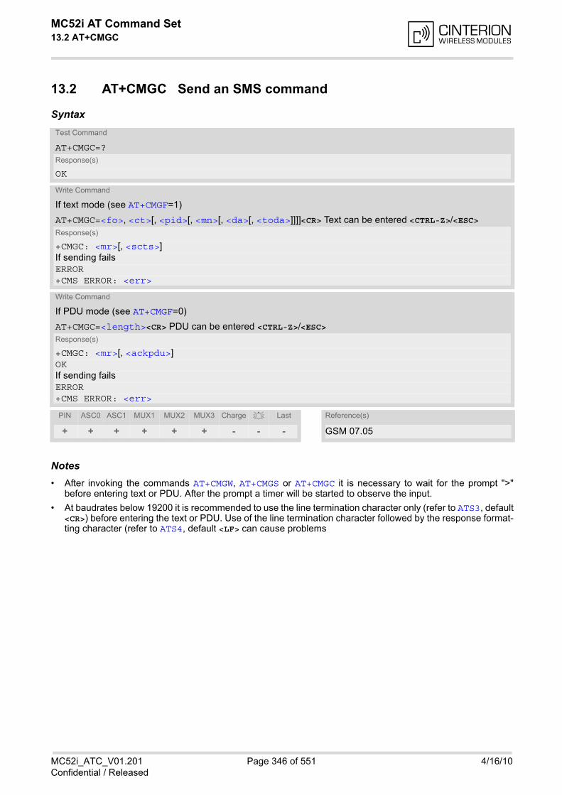
MC52i AT Command Set 13.2 AT+CMGC
MC52i_ATC_V01.201 Page 346 of 551 4/16/10Confidential / Released
13.2 AT+CMGC Send an SMS command
Syntax
Notes• After invoking the commands AT+CMGW, AT+CMGS or AT+CMGC it is necessary to wait for the prompt ">"
before entering text or PDU. After the prompt a timer will be started to observe the input.
• At baudrates below 19200 it is recommended to use the line termination character only (refer to ATS3, default<CR>) before entering the text or PDU. Use of the line termination character followed by the response format-ting character (refer to ATS4, default <LF> can cause problems
Test Command
AT+CMGC=?Response(s)
OK
Write Command
If text mode (see AT+CMGF=1)
AT+CMGC=<fo>, <ct>[, <pid>[, <mn>[, <da>[, <toda>]]]]<CR> Text can be entered <CTRL-Z>/<ESC>Response(s)
+CMGC: <mr>[, <scts>]If sending failsERROR+CMS ERROR: <err>
Write Command
If PDU mode (see AT+CMGF=0)
AT+CMGC=<length><CR> PDU can be entered <CTRL-Z>/<ESC>Response(s)
+CMGC: <mr>[, <ackpdu>]OKIf sending failsERROR+CMS ERROR: <err>
PIN ASC0 ASC1 MUX1 MUX2 MUX3 Charge Last Reference(s)
+ + + + + + - - - GSM 07.05

MC52i AT Command Set 13.3 AT+CMGD
MC52i_ATC_V01.201 Page 347 of 551 4/16/10Confidential / Released
13.3 AT+CMGD Delete short message
The write command deletes a short message from the preferred message storage <mem1> location <index>.
Syntax
Notes• If there is no short message stored at the selected index, the response is OK too.
• Users should be aware that when using this AT command quickly after SIM PIN authentication the SIM datamay not yet be accessible, resulting in a short delay before the requested AT command response is returned.See Section 20.1, Restricted access to SIM data after SIM PIN authentication for further detail.
Test Command
AT+CMGD=?Response(s)
OK
Write Command
AT+CMGD=<index>Response(s)
OKERROR+CMS ERROR: <err>
PIN ASC0 ASC1 MUX1 MUX2 MUX3 Charge Last Reference(s)
+ + + + + + - - - GSM 07.05
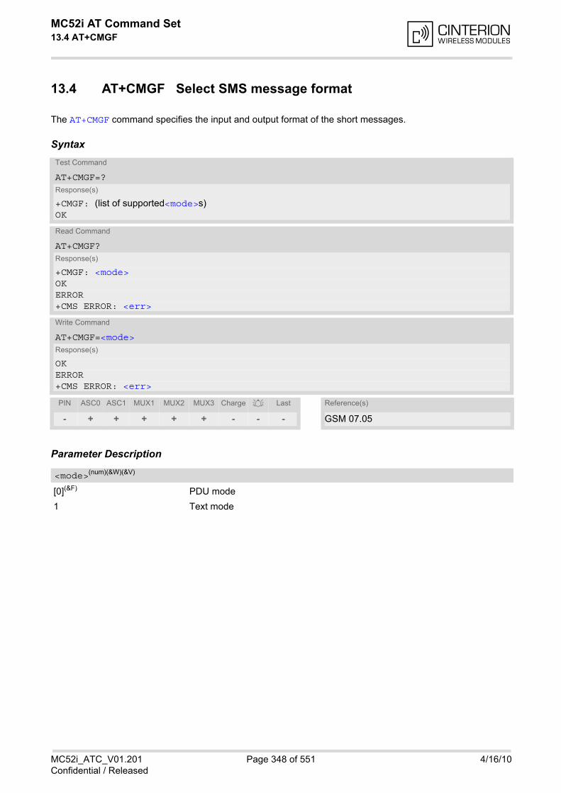
MC52i AT Command Set 13.4 AT+CMGF
MC52i_ATC_V01.201 Page 348 of 551 4/16/10Confidential / Released
13.4 AT+CMGF Select SMS message format
The AT+CMGF command specifies the input and output format of the short messages.
Syntax
Parameter Description
[0](&F) PDU mode
1 Text mode
Test Command
AT+CMGF=?Response(s)
+CMGF: (list of supported<mode>s)OK
Read Command
AT+CMGF?Response(s)
+CMGF: <mode>OKERROR+CMS ERROR: <err>
Write Command
AT+CMGF=<mode>Response(s)
OKERROR+CMS ERROR: <err>
PIN ASC0 ASC1 MUX1 MUX2 MUX3 Charge Last Reference(s)
- + + + + + - - - GSM 07.05
<mode>(num)(&W)(&V)

MC52i AT Command Set 13.5 AT+CMGL
MC52i_ATC_V01.201 Page 349 of 551 4/16/10Confidential / Released
13.5 AT+CMGL List SMS messages from preferred store
The write command returns messages with status value <stat> from message storage <mem1> to the TE. If thestatus of the message is 'received unread', the status in the storage changes to 'received read'.The execute command is the same as the write command with the given default for <stat>.
SyntaxTest Command
AT+CMGL=?Response(s)
+CMGL: (list of supported <stat>s)OK
Exec Command
AT+CMGLResponse(s)
+CMGL: (see write command for default of <stat>)OK
Write Command
AT+CMGL=<stat>Response(s)
Output if text mode (AT+CMGF=1) and command successful: For SMS- SUBMITs and/or SMS-DELIVERs +CMGL: <index>, <stat>, <oa>/<da>, [<alpha>], [<scts>][, <tooa>/<toda>, <length>]<data>[... ]OK
For SMS-STATUS-REPORTs +CMGL: <index>, <stat>, <fo>, <mr>, [<ra>], [<tora>], <scts>, <dt>, <st>[... ]OK
For SMS-Commands +CMGL: <index>, <stat>, <fo>, <ct>[... ]OK
Output if PDU mode AT+CMGF=0 and command successful: For SMS-SUBMITs and/or SMS-DELIVERs +CMGL: <index>, <stat>, [<alpha>], <length><pdu>[... ]OK
If error is related to ME functionalityERROR+CMS ERROR: <err>
PIN ASC0 ASC1 MUX1 MUX2 MUX3 Charge Last Reference(s)
+ + + + + + - - - GSM 07.05
MC52i AT Command Set 13.5 AT+CMGL
MC52i_ATC_V01.201 Page 350 of 551 4/16/10Confidential / Released
Notes• The selected <mem1> can contain different types of SMs (e.g. SMS-DELIVERs, SMS-SUBMITs, SMS-STA-
TUS-REPORTs and SMS-COMMANDs), the response may be a mix of the responses of different SM types.TE application can recognize the response format by examining the third response parameter.
• The parameters <ra> and <tora> will only be displayed if parameter <ra> of the AT^SSCONF command isset to 1.
• Users should be aware that when using this AT command quickly after SIM PIN authentication the SIM datamay not yet be accessible, resulting in a short delay before the requested AT command response is returned.See Section 20.1, Restricted access to SIM data after SIM PIN authentication for further detail.

MC52i AT Command Set 13.6 AT+CMGR
MC52i_ATC_V01.201 Page 351 of 551 4/16/10Confidential / Released
13.6 AT+CMGR Read SMS messages
The write command returns SMS message with location value <index> from message storage <mem1> to theTE. If status of the message is 'received unread', status in the storage changes to 'received read'.
SyntaxTest Command
AT+CMGR=?Response(s)
OK
Write Command
AT+CMGR=<index>Response(s)
Output if text mode (AT+CMGF=1) and command successful: For SMS-DELIVER +CMGR: <stat>, <oa>, [<alpha>], <scts>[, <tooa>, <fo>, <pid>, <dcs>, <sca>, <tosca>, <length>]<data>[... ]OK
For SMS-SUBMIT +CMGR: <stat>, <da>, [<alpha>][, <toda>, <fo>, <pid>, <dcs>, [<vp>], <sca>, <tosca>, <length>]<data>[... ]OK
For SMS-STATUS-REPORT +CMGR: <stat>, <fo>, <mr>, [<ra>], [<tora>], <scts>, <dt>, <st><data>[... ]OK
For SMS-Commands +CMGR: <stat>, <fo>, <ct>[, <pid>, [<mn>], [<da>], [<toda>], <length>]<data>[... ]OK
Output if PDU mode (AT+CMGF=0) and command successful: For SMS-SUBMITs and/or SMS-DELIVERs +CMGR: <stat>, [<alpha>], <length><pdu>[... ]OKERROR+CMS ERROR: <err>
PIN ASC0 ASC1 MUX1 MUX2 MUX3 Charge Last Reference(s)
+ + + + + + - - - GSM 07.05
MC52i AT Command Set 13.6 AT+CMGR
MC52i_ATC_V01.201 Page 352 of 551 4/16/10Confidential / Released
Notes• Response if AT+CMGR is used to read an empty record index: +CMGR: 0,,0
• Response if AT+CMGR is used to read a non-existent record index: +CMS ERROR: invalid memory index
• The parameters <ra> and <tora> will only be displayed if parameter <ra> of the AT^SSCONF command isset to 1.
• Users should be aware that when using this AT command quickly after SIM PIN authentication the SIM datamay not yet be accessible, resulting in a short delay before the requested AT command response is returned.See Section 20.1, Restricted access to SIM data after SIM PIN authentication for further detail.
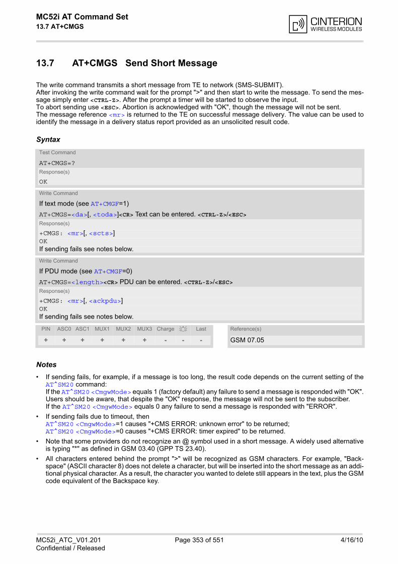
MC52i AT Command Set 13.7 AT+CMGS
MC52i_ATC_V01.201 Page 353 of 551 4/16/10Confidential / Released
13.7 AT+CMGS Send Short Message
The write command transmits a short message from TE to network (SMS-SUBMIT).After invoking the write command wait for the prompt ">" and then start to write the message. To send the mes-sage simply enter <CTRL-Z>. After the prompt a timer will be started to observe the input.To abort sending use <ESC>. Abortion is acknowledged with "OK", though the message will not be sent.The message reference <mr> is returned to the TE on successful message delivery. The value can be used toidentify the message in a delivery status report provided as an unsolicited result code.
Syntax
Notes• If sending fails, for example, if a message is too long, the result code depends on the current setting of the
AT^SM20 command:If the AT^SM20 <CmgwMode> equals 1 (factory default) any failure to send a message is responded with "OK".Users should be aware, that despite the "OK" response, the message will not be sent to the subscriber.If the AT^SM20 <CmgwMode> equals 0 any failure to send a message is responded with "ERROR".
• If sending fails due to timeout, then AT^SM20 <CmgwMode>=1 causes "+CMS ERROR: unknown error" to be returned;AT^SM20 <CmgwMode>=0 causes "+CMS ERROR: timer expired" to be returned.
• Note that some providers do not recognize an @ symbol used in a short message. A widely used alternativeis typing "*" as defined in GSM 03.40 (GPP TS 23.40).
• All characters entered behind the prompt ">" will be recognized as GSM characters. For example, "Back-space" (ASCII character 8) does not delete a character, but will be inserted into the short message as an addi-tional physical character. As a result, the character you wanted to delete still appears in the text, plus the GSMcode equivalent of the Backspace key.
Test Command
AT+CMGS=?Response(s)
OK
Write Command
If text mode (see AT+CMGF=1)
AT+CMGS=<da>[, <toda>]<CR> Text can be entered. <CTRL-Z>/<ESC>Response(s)
+CMGS: <mr>[, <scts>]OKIf sending fails see notes below.
Write Command
If PDU mode (see AT+CMGF=0)
AT+CMGS=<length><CR> PDU can be entered. <CTRL-Z>/<ESC>Response(s)
+CMGS: <mr>[, <ackpdu>]OKIf sending fails see notes below.
PIN ASC0 ASC1 MUX1 MUX2 MUX3 Charge Last Reference(s)
+ + + + + + - - - GSM 07.05

MC52i AT Command Set 13.7 AT+CMGS
MC52i_ATC_V01.201 Page 354 of 551 4/16/10Confidential / Released
• Message Length in Text ModeThe maximum length of a short message depends on the used coding scheme: It is 160 characters if the 7bit GSM coding scheme is used, and 140 characters according to the 8 bit GSM coding scheme.In case UCS2 character set selected it is highly recommended to set Data Coding Scheme (<dcs> ofAT+CSMP) to 16-bit data, otherwise the length of sms user data is restricted to 88 octets. Even better for mes-sages with UCS2 character set is the PDU Mode.
• At baudrates lower than 19200 it is recommended to use the line termination character only (refer to <n> ofATS3, default <CR>) before entering text or PDU. Use of the line termination character followed by theresponse formatting character (see <n> of ATS4, default <LF>) can cause problems.
• During a pending USSD user interaction the AT+CMGS write command returns "+CME ERROR: operationtemporary not allowed" to prevent blocking situations.
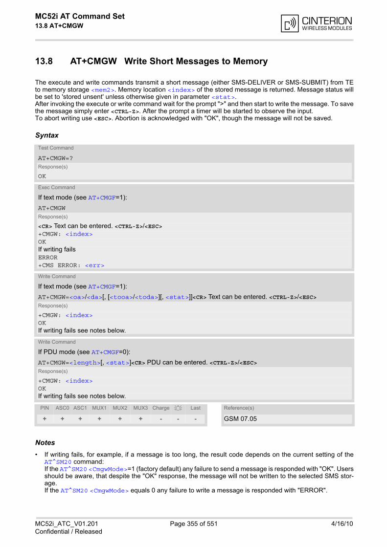
MC52i AT Command Set 13.8 AT+CMGW
MC52i_ATC_V01.201 Page 355 of 551 4/16/10Confidential / Released
13.8 AT+CMGW Write Short Messages to Memory
The execute and write commands transmit a short message (either SMS-DELIVER or SMS-SUBMIT) from TEto memory storage <mem2>. Memory location <index> of the stored message is returned. Message status willbe set to 'stored unsent' unless otherwise given in parameter <stat>.After invoking the execute or write command wait for the prompt ">" and then start to write the message. To savethe message simply enter <CTRL-Z>. After the prompt a timer will be started to observe the input.To abort writing use <ESC>. Abortion is acknowledged with "OK", though the message will not be saved.
Syntax
Notes• If writing fails, for example, if a message is too long, the result code depends on the current setting of the
AT^SM20 command:If the AT^SM20 <CmgwMode>=1 (factory default) any failure to send a message is responded with "OK". Usersshould be aware, that despite the "OK" response, the message will not be written to the selected SMS stor-age.If the AT^SM20 <CmgwMode> equals 0 any failure to write a message is responded with "ERROR".
Test Command
AT+CMGW=?Response(s)
OK
Exec Command
If text mode (see AT+CMGF=1):
AT+CMGWResponse(s)
<CR> Text can be entered. <CTRL-Z>/<ESC> +CMGW: <index>OKIf writing failsERROR+CMS ERROR: <err>
Write Command
If text mode (see AT+CMGF=1):
AT+CMGW=<oa>/<da>[, [<tooa>/<toda>][, <stat>]]<CR> Text can be entered. <CTRL-Z>/<ESC>Response(s)
+CMGW: <index>OKIf writing fails see notes below.
Write Command
If PDU mode (see AT+CMGF=0):
AT+CMGW=<length>[, <stat>]<CR> PDU can be entered. <CTRL-Z>/<ESC>Response(s)
+CMGW: <index>OKIf writing fails see notes below.
PIN ASC0 ASC1 MUX1 MUX2 MUX3 Charge Last Reference(s)
+ + + + + + - - - GSM 07.05
MC52i AT Command Set 13.8 AT+CMGW
MC52i_ATC_V01.201 Page 356 of 551 4/16/10Confidential / Released
• If writing fails due to timeout, then AT^SM20 <CmgwMode>=1 causes "+CMS ERROR: unknown error" to be returned;AT^SM20 <CmgwMode>=0 causes "+CMS ERROR: timer expired" to be returned.
• Note that some providers do not recognize an @ symbol used in a short message. A widely used alternativeis typing "*" as defined in GSM 03.40 (GPP TS 23.40).
• For baudrates lower than 19200 it is recommended to use the line termination character only (refer to ATS3=<n>, default <CR>) before entering the text or PDU. Use of the line termination character followed by theresponse formating character (see ATS4= <n>, default <LF>) may cause problems.
• SMS-COMMANDs and SMS-STATUS-REPORTs cannot be stored in text mode.
• All characters entered behind the ">" prompt will be recognized as GSM characters. For example, "Back-space" (ASCII character 8) does not delete a character, but will be inserted into the short message as an addi-tional physical character. As a result, the character you wanted to delete still appears in the text, plus the GSMcode equivalent of the Backspace key.
• Message Length in Text ModeThe maximum length of a short message depends on the used coding scheme: It is 160 characters if the 7bit GSM coding scheme is used, and 140 characters according to the 8 bit GSM coding scheme.In case UCS2 character set selected it is highly recommended to set Data Coding Scheme (<dcs> ofAT+CSMP) to 16-bit data, otherwise the length of sms user data is restricted to 88 octets. Even better for mes-sages with UCS2 character set is the PDU Mode.
• The length of 8-bit data coded short messages has to be greater than 0.
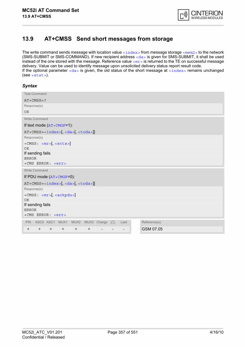
MC52i AT Command Set 13.9 AT+CMSS
MC52i_ATC_V01.201 Page 357 of 551 4/16/10Confidential / Released
13.9 AT+CMSS Send short messages from storage
The write command sends message with location value <index> from message storage <mem2> to the network(SMS-SUBMIT or SMS-COMMAND). If new recipient address <da> is given for SMS-SUBMIT, it shall be usedinstead of the one stored with the message. Reference value <mr> is returned to the TE on successful messagedelivery. Value can be used to identify message upon unsolicited delivery status report result code.If the optional parameter <da> is given, the old status of the short message at <index> remains unchanged(see <stat>).
SyntaxTest Command
AT+CMSS=?Response(s)
OK
Write Command
If text mode (AT+CMGF=1):
AT+CMSS=<index>[, <da>[, <toda>]]Response(s)
+CMSS: <mr>[, <scts>]OKIf sending failsERROR+CMS ERROR: <err>
Write Command
If PDU mode (AT+CMGF=0):
AT+CMSS=<index>[, <da>[, <toda>]]Response(s)
+CMSS: <mr>[, <ackpdu>]OKIf sending failsERROR+CMS ERROR: <err>
PIN ASC0 ASC1 MUX1 MUX2 MUX3 Charge Last Reference(s)
+ + + + + + - - - GSM 07.05

MC52i AT Command Set 13.10 AT+CNMA
MC52i_ATC_V01.201 Page 358 of 551 4/16/10Confidential / Released
13.10 AT+CNMA New Message Acknowledgement to ME/TE, only phase 2+
The write / execute command confirms successful receipt of a new message (SMS-DELIVER or SMS-STATUS-REPORT) routed directly to the TE. TA shall not send another +CMT or +CDS result code to TE until previousone is acknowledged. If ME does not receive acknowledgement within required time (network time-out), MEsends RP-ERROR to the network. TA shall automatically disable routing to TE by setting both <mt> and <ds>values of AT+CNMI to zero.
Syntax
Parameter Description
Parameter required only for PDU mode.
0 Command operates similarly as in text mode.
Notes• The execute / write command shall only be used when AT+CSMS parameter <service> equals 1 (= phase
2+).
• The execute command can be used no matter whether text mode or PDU mode is activated. The write com-mand is designed for the PDU mode only.
• If multiplex mode is activated (AT+CMUX=0) the AT+CNMI parameter will be set to zero on all channels, if onechannel fails to acknowledge an incoming message within the required time.
Test Command
AT+CNMA=?Response(s)
+CNMA: (list of supported <n>s)OK
Exec Command
AT+CNMAResponse(s)
OKERROR+CMS ERROR: <err>
Write Command
AT+CNMA=<n>Response(s)
OKERROR+CMS ERROR: <err>
PIN ASC0 ASC1 MUX1 MUX2 MUX3 Charge Last Reference(s)
+ + + + + + - - - GSM 07.05
<n>(num)

MC52i AT Command Set 13.11 AT+CNMI
MC52i_ATC_V01.201 Page 359 of 551 4/16/10Confidential / Released
13.11 AT+CNMI New short Message Indication
The write command selects the procedure how the receipt of new short messages from the network is indicatedto the TE when TE is active, e.g. DTR signal is ON. If TE is inactive (e.g. DTR signal is OFF), message receivingshould be done as specified in GSM 03.38. If the DTR signal is not available or the state of the signal is ignored(V.250 command AT&D0, reliable message transfer can be assured by using AT+CNMA acknowledgment proce-dure. The rules <mt>=2 and <mt>=3 for storing received messages are possible only if phase 2+ compatibilityis activated with AT+CSMS=1. The parameter <ds>=1 is only available in phase 2+
Syntax
Unsolicited Result Codes
URC 1
<mt>=1:
+CMTI: <mem3>, <index>
Indicates that new message has been received
URC 2
<mt>=2 (PDU mode enabled):
+CMT: <length><CR><LF><pdu>
Indicates that new message has been received
URC 3
<mt>=2 (text mode enabled):
+CMT: <oa>, <scts>[, <tooa>, <fo>, <pid>, <dcs>, <sca>, <tosca>, <length>]<CR><LF><data>
Indicates that new message has been received
Test Command
AT+CNMI=?Response(s)
+CNMI: (list of supported<mode>s), (list of supported <mt>s), (list of supported <bm>s), (list of supported <ds>s), (list of supported <bfr>s)OK
Read Command
AT+CNMI?Response(s)
+CNMI: <mode>, <mt>, <bm>, <ds>, <bfr>OK
Write Command
AT+CNMI=<mode>[, <mt>[, <bm>[, <ds>[, <bfr>]]]]Response(s)
OKERROR+CMS ERROR: <err>
PIN ASC0 ASC1 MUX1 MUX2 MUX3 Charge Last Reference(s)
+ + + + + + - - - GSM 07.05
MC52i AT Command Set 13.11 AT+CNMI
MC52i_ATC_V01.201 Page 360 of 551 4/16/10Confidential / Released
URC 4
<bm>=2 (PDU mode enabled):
+CBM: <length><CR><LF><pdu>
Indicates that new cell broadcast message has been received
URC 5
<bm>=2 (text mode enabled):
+CBM: <sn>, <mid>, <dcs>, <page>, <pages><CR><LF><data>
Indicates that new cell broadcast message has been received
URC 6
<ds>=1 (PDU mode enabled):
+CDS: <length><CR><LF><pdu>
Indicates that new SMS status report has been received
URC 7
<ds>=1 (text mode enabled):
+CDS: <fo>, <mr>[, <ra>][, <tora>], <scts>, <dt>, <st>
Indicates that new SMS status report has been received
URC 8
<ds>=2:
+CDSI: <mem3>, <index>
Indicates that new SMS status report has been received
Parameter Description
[0](&F) Buffer unsolicited result codes in the TA. If TA result code buffer is full, indica-tions can be buffered in some other place or the oldest indications may be dis-carded and replaced with the new received indications.
1 Discard indication and reject new received message unsolicited result codeswhen TA-TE link is reserved (e.g. in on-line data mode). Otherwise forwardthem directly to the TE.
2 Buffer unsolicited result codes in the TA when TA-TE link is reserved (e.g. inonline data mode) and flush them to the TE after reservation. Otherwise for-ward them directly to the TE.
3 Forward unsolicited result codes directly to the TE. When TA-TE link isreserved (e.g. in online data mode) the URCs are signaled according to theAT^SCFG parameters <uri>, <udri> and <urat>.
Rules for storing received short messages depend on the relevant data coding method (refer to GSM 03.38),preferred memory storage (AT+CPMS) setting and this value.Note: If AT command interface is acting as the only display device, the ME must support storage of class 0 mes-sages and messages in the message waiting indication group (discard message)
[0](&F) No SMS-DELIVER indications are routed to the TE.
1 If SMS-DELIVER is stored in ME/TA, indication of the memory location isrouted to the TE using unsolicited result code.
<mode>(num)(&W)
<mt>(num)(&W)(&V)

MC52i AT Command Set 13.11 AT+CNMI
MC52i_ATC_V01.201 Page 361 of 551 4/16/10Confidential / Released
2 SMS-DELIVERs, except class 2 messages and messages in the messagewaiting indication group (store message) are routed directly to the TE usingunsolicited result code.
3 Class 3 SMS-DELIVERs are routed directly to the TE using unsolicited resultcodes defined in <mt>=2. Messages of other data coding schemes result inindication as defined in <mt>=1.
Rules for storing received CBMs depend on the relevant data coding method (refer to GSM 03.38), the settingof Select CBM Types (AT+CSCB) and this value:
[0](&F) No CBM indications are routed to the TE.
2 New CBMs are routed directly to the TE using unsolicited result code.
3 Class 3 CBMs are routed directly to TE using unsolicited result codes definedin <bm>=2.
[0](&F) No SMS-STATUS-REPORTs are routed to the TE.
1 SMS-STATUS-REPORTs are routed to the TE using unsolicited result code.
2 If SMS-STATUS-REPORT is routed into ME/TA, indication of the memorylocation is routed to the TE using unsolicited result code.
[1](&F) TA buffer of unsolicited result codes defined within this command is clearedwhen <mode> changes from 0 to 1...3.
Integer type; value in the range of location numbers supported by the associated memory
Notes• Parameters <mt>=2,3 and <ds>=1 are only available with GSM phase 2+ (see AT+CSMS=1). Incoming SMs
or Status Reports have to be acknowledged with AT+CNMA=0 when using these phase 2+ parameters.
• Requirements specific to Multiplex mode:In multiplex mode (AT+CMUX=0) only one channel can use a phase 2+ parameter. The parameter for <mt>and <ds> on the other channels have to be set to zero. If either a SM or a Status Report is not acknowledged,all AT+CNMI parameter in all channels will be set to zero.
• If the ME operates on different instances (MUX channels 1, 2, 3 or ASC0/ASC1) avoid different settings forrouting and indicating short messages. For example, if messages shall be routed directly to one instance ofthe TE (set with AT+CNMI, AT^SSDA), it is not possible to activate the presentation of URCs with AT+CMERor AT+CNMI on another instance. Any attempt to activate settings that conflict with existing settings onanother interface, will result in "+CME ERROR", or accordingly "+CMS ERROR".
• Handling of Class 0 short messages: If the host application is provided with a display and AT^SSDA=1 has been set Class 0 short messages canbe displayed immediately.If the host application does not include a display, ME handles Class 0 short messages as though there wasno message class, i.e. it will ignore bits 0 and 1 in the <dcs> and normal rules for exceeded memory capacityshall apply. This approach is compliant with GSM 03.38 .
• The parameters <ra> and <tora> will only be displayed if <ra> of the AT^SSCONF command is set to 1.
• If either a SM or a Status Report is not acknowledged, all AT+CNMI parameter in all channels will be set tozero.
<bm>(num)(&W)(&V)
<ds>(num)(&W)(&V)
<bfr>(num)(&V)
<index>(num)
MC52i AT Command Set 13.12 AT+CPMS
MC52i_ATC_V01.201 Page 362 of 551 4/16/10Confidential / Released
13.12 AT+CPMS Preferred SMS message storage
The write command selects memory storages <mem1>,<mem2>, <mem3> to be used for reading, writing, etc.
Syntax
Parameter Description
Number of messages currently in <mem1>
Number of messages currently in <mem2>
Number of messages currently in <mem3>
Number of messages storable in <mem1>
Number of messages storable in <mem2>
Number of messages storable in <mem3>
Test Command
AT+CPMS=?Response(s)
+CPMS: (list of supported <mem1>s), (list of supported <mem2>s), (list of supported <mem3>s)OK
Read Command
AT+CPMS?Response(s)
+CPMS: <mem1>, <used1>, <total1>, <mem2>, <used2>, <total2>, <mem3>, <used3>, <total3>OKERROR+CMS ERROR: <err>
Write Command
AT+CPMS=<mem1>[, <mem2>[, <mem3>]]Response(s)
+CPMS: <used1>, <total1>, <used2>, <total2>, <used3>, <total3>OKERROR+CMS ERROR: <err>
PIN ASC0 ASC1 MUX1 MUX2 MUX3 Charge Last Reference(s)
+ + + + + + - - - GSM 07.05
<used1>(num)
<used2>(num)
<used3>(num)
<total1>(num)
<total2>(num)
<total3>(num)
MC52i AT Command Set 13.12 AT+CPMS
MC52i_ATC_V01.201 Page 363 of 551 4/16/10Confidential / Released
Notes• The Mobile Equipment storage ''ME'' offers space for 25 short messages, see <mem1>.
• ''MT'' is the sum of ''ME'' (= 25 locations) and ''SM'' (capacity varies with SIM card). The indices <index> ofthe ''MT'' storage are dependent on the order selected with AT^SSMSS
• The <mem1>, <mem2> and <mem3> parameter will be stored in non-volatile memory.
• The user should be aware that the setting ''MT'' involves ''ME'' and ''SM'', with ''ME'' being filled up first. If the''ME'' storage is full, MC52i will proceed with the ''SM'' storage. Incoming Class 1 short messages (ME specific) will be preferably stored to ''ME'' and may be transferred tothe ''SM'' storage if ''ME'' is used up. Incoming Class 2 messages (SIM specific) will be stored to the SIM card only, no matter whether or not thereis free ''ME'' space. As a result, the ^SMGO: 2 indication (see AT^SMGO) may be presented without prior indi-cation of ^SMGO: 1. For more information regarding SIM and ME specific message classes refer to <dcs>and the following specifications: GSM 03.38 and 3GPP TS23038.
• When <mem3> is switched over from ''MT'' to ''SM'' all free ''ME'' locations will be filled with dummy short mes-sages. This procedure can take up to 35 seconds, until all the 25 records are written. If switching from ''MT'' to ''SM'' was not finished due to error or user break, the value of <mem3> remains ''MT'',but some of the dummy records remain in the ''ME'' storage. These records have to be deleted manually.When <mem3> equals ''SM'', do not delete the dummy messages in the ''ME''. storage. They will be automat-ically deleted when you switch back from ''SM'' to ''MT''. Again, this may take up to 35 seconds. If switching from ''SM'' to ''MT'' was not finished due to an error or user break, the value of <mem3> remains''SM'', but the ''ME'' storage will no longer be filled with dummy records. New incoming short messages maynow be written to the ''ME'' storage, if ''SM'' is already full. To avoid this, repeat the AT+CPMS command assoon as possible to switch <mem3> back to ''MT''. As an alternative, you can manually delete the dummyrecords and issue AT+CPMS=MT,MT,MT.
• Multiplexer: In Multiplex mode or when the two physical serial interfaces are connected, the parameter<mem3> will be the same on all instances, but the settings of <mem1> and <mem2> may vary on each channel/ interface. As a result, changes on parameter <mem1> and/or <mem2> befor activating the multiplexer or dif-ferences values for other instanes can result in not desired behaviours like different outputs for AT+CMGL andso on.
• While <mem3> equals ''SM'' and <mem1> equals ''ME'' it is possible that, after deleting short messages from''ME'', the freed space on ''ME'' is reclaimed for new incoming short messages, when there is no space left onthe ''SM'' storage. As it is often the clients concern to have received short messages stored only to the SIMcard, inconsistent settings should be generally avoided. This can be achieved simply by using the sameparameter for all memory indices.
• Users should be aware that when using this AT command quickly after SIM PIN authentication the SIM datamay not yet be accessible, resulting in a short delay before the requested AT command response is returned.See Section 20.1, Restricted access to SIM data after SIM PIN authentication for further detail.
• The indices <index> of the storage are dependent on the order selected with AT^SSMSS.
MC52i AT Command Set 13.13 AT+CSCA
MC52i_ATC_V01.201 Page 364 of 551 4/16/10Confidential / Released
13.13 AT+CSCA SMS Service Center Address
Write command updates the SMSC address, through which mobile originated SMs are transmitted. In text mode,setting is used by send and write commands. In PDU mode, setting is used by the same commands, but onlywhen the length of the SMSC address coded into the <pdu> parameter equals zero.
Syntax
Notes• In case of using no parameter after AT+CSCA= the content of <sca> will be deleted.
• This command writes the service center address to non-volatile memo.
• The SMS service center address should be entered as specified by the service provider.
Test Command
AT+CSCA=?Response(s)
OK
Read Command
AT+CSCA?Response(s)
+CSCA: <sca>, <tosca>OK
Write Command
AT+CSCA=<sca>[, <tosca>]Response(s)
OK
PIN ASC0 ASC1 MUX1 MUX2 MUX3 Charge Last Reference(s)
+ + + + + + - - - GSM 07.05

MC52i AT Command Set 13.14 AT+CSCB
MC52i_ATC_V01.201 Page 365 of 551 4/16/10Confidential / Released
13.14 AT+CSCB Select Cell Broadcast Message Indication
The test command returns the supported modes as a compound value.The write command selects which types of CBMs are to be received by the ME.
Syntax
Parameter Description
Message mode
0(&F) Accept messages that are defined in <mids> and <dcss>
1 Forbid messages that are defined in <mids> and <dcss>
Cell Broadcast Message ID specification
[““](&F) default value of this parameter is empty string, and it means that no CBM iden-tifiers are specified.
• For <mode>=0: Six different possible combinations of CBM IDs (e.g. "0,1,5,320-478,922,2000-3000"). In certain configurations, e.g. if using SIMs that contain data in Elementary File EF-CBMID (Cell BroadcastMessage Identifier for Data download) less than six combinations may be available. To access a SIM's Elementary File data refer to command AT+CRSM.
• For <mode>=1: One CBM ID or range of IDs (e.g. "320-478").
CBM data coding scheme specification
[““](&F) default value of this parameter is empty string
All different possible combinations of CBM data coding schemes (e.g. "0-3,5"). Using default empty string leadsto get all CBMs independent of their dcss. A given <dcss> replaces any former value and is used for consecutive requests.
Test Command
AT+CSCB=?Response(s)
+CSCB: (list of supported <mode>s)OK
Read Command
AT+CSCB?Response(s)
+CSCB: <mode>, <mids>, <dcss>OK
Write Command
AT+CSCB=<mode>[, <mids>[, <dcss>]]Response(s)
OK
PIN ASC0 ASC1 MUX1 MUX2 MUX3 Charge Last Reference(s)
+ + + + + + - - - GSM 07.05
<mode>(num)
<mids>(str)
<dcss>(str)
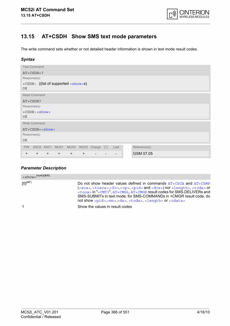
MC52i AT Command Set 13.15 AT+CSDH
MC52i_ATC_V01.201 Page 366 of 551 4/16/10Confidential / Released
13.15 AT+CSDH Show SMS text mode parameters
The write command sets whether or not detailed header information is shown in text mode result codes.
Syntax
Parameter Description
[0](&F) Do not show header values defined in commands AT+CSCA and AT+CSMP(<sca>, <tosca>,<fo>,<vp>, <pid> and <dcs>) nor <length>, <toda> or<tooa> in "+CMTI", AT+CMGL, AT+CMGR result codes for SMS-DELIVERs andSMS-SUBMITs in text mode; for SMS-COMMANDs in +CMGR result code, donot show <pid>,<mn>,<da>, <toda>, <length> or <cdata>
1 Show the values in result codes
Test Command
AT+CSDH=?Response(s)
+CSDH: ((list of supported <show>s)OK
Read Command
AT+CSDH?Response(s)
+CSDH:<show>OK
Write Command
AT+CSDH=<show>Response(s)
OK
PIN ASC0 ASC1 MUX1 MUX2 MUX3 Charge Last Reference(s)
+ + + + + + - - - GSM 07.05
<show>(num)(&W)
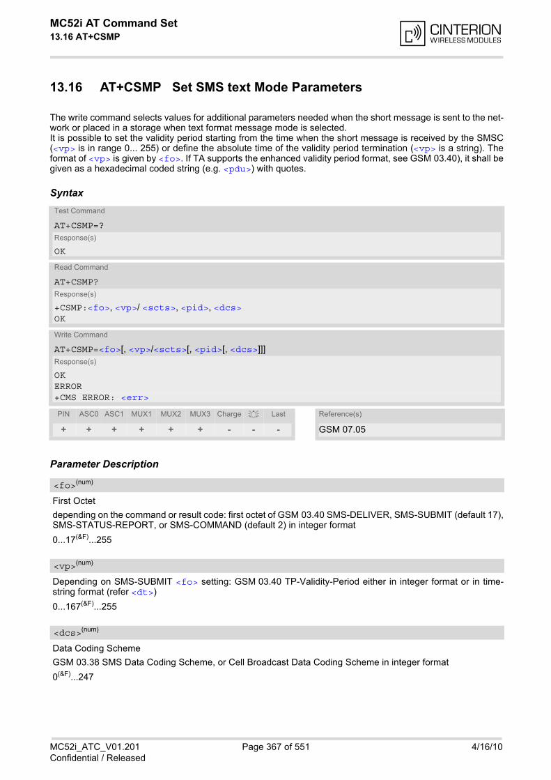
MC52i AT Command Set 13.16 AT+CSMP
MC52i_ATC_V01.201 Page 367 of 551 4/16/10Confidential / Released
13.16 AT+CSMP Set SMS text Mode Parameters
The write command selects values for additional parameters needed when the short message is sent to the net-work or placed in a storage when text format message mode is selected. It is possible to set the validity period starting from the time when the short message is received by the SMSC(<vp> is in range 0... 255) or define the absolute time of the validity period termination (<vp> is a string). Theformat of <vp> is given by <fo>. If TA supports the enhanced validity period format, see GSM 03.40), it shall begiven as a hexadecimal coded string (e.g. <pdu>) with quotes.
Syntax
Parameter Description
First Octet
depending on the command or result code: first octet of GSM 03.40 SMS-DELIVER, SMS-SUBMIT (default 17),SMS-STATUS-REPORT, or SMS-COMMAND (default 2) in integer format
0...17(&F)...255
Depending on SMS-SUBMIT <fo> setting: GSM 03.40 TP-Validity-Period either in integer format or in time-string format (refer <dt>)
0...167(&F)...255
Data Coding Scheme
GSM 03.38 SMS Data Coding Scheme, or Cell Broadcast Data Coding Scheme in integer format
0(&F)...247
Test Command
AT+CSMP=?Response(s)
OK
Read Command
AT+CSMP?Response(s)
+CSMP:<fo>, <vp>/ <scts>, <pid>, <dcs>OK
Write Command
AT+CSMP=<fo>[, <vp>/<scts>[, <pid>[, <dcs>]]]Response(s)
OKERROR+CMS ERROR: <err>
PIN ASC0 ASC1 MUX1 MUX2 MUX3 Charge Last Reference(s)
+ + + + + + - - - GSM 07.05
<fo>(num)
<vp>(num)
<dcs>(num)

MC52i AT Command Set 13.16 AT+CSMP
MC52i_ATC_V01.201 Page 368 of 551 4/16/10Confidential / Released
Protocol Identifier
GSM 03.40 TP-Protocol-Identifier in integer format
0(&F)...255
Notes• When storing a SMS DELIVER from the TE to the preferred memory storage in text mode (using the AT+CMGW
write command), <vp> field can be used for <scts>.
• The command writes the parameters to the non-volatile memory.
<pid>(num)
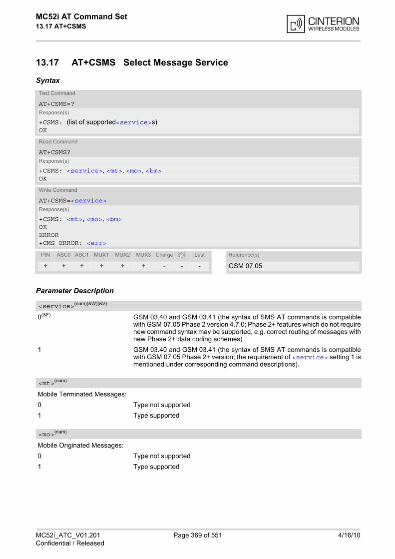
MC52i AT Command Set 13.17 AT+CSMS
MC52i_ATC_V01.201 Page 369 of 551 4/16/10Confidential / Released
13.17 AT+CSMS Select Message Service
Syntax
Parameter Description
0(&F) GSM 03.40 and GSM 03.41 (the syntax of SMS AT commands is compatiblewith GSM 07.05 Phase 2 version 4.7.0; Phase 2+ features which do not requirenew command syntax may be supported, e.g. correct routing of messages withnew Phase 2+ data coding schemes)
1 GSM 03.40 and GSM 03.41 (the syntax of SMS AT commands is compatiblewith GSM 07.05 Phase 2+ version; the requirement of <service> setting 1 ismentioned under corresponding command descriptions).
Mobile Terminated Messages:
0 Type not supported
1 Type supported
Mobile Originated Messages:
0 Type not supported
1 Type supported
Test Command
AT+CSMS=?Response(s)
+CSMS: (list of supported<service>s)OK
Read Command
AT+CSMS?Response(s)
+CSMS: <service>, <mt>, <mo>, <bm>OK
Write Command
AT+CSMS=<service>Response(s)
+CSMS: <mt>, <mo>, <bm>OKERROR+CMS ERROR: <err>
PIN ASC0 ASC1 MUX1 MUX2 MUX3 Charge Last Reference(s)
+ + + + + + - - - GSM 07.05
<service>(num)(&W)(&V)
<mt>(num)
<mo>(num)
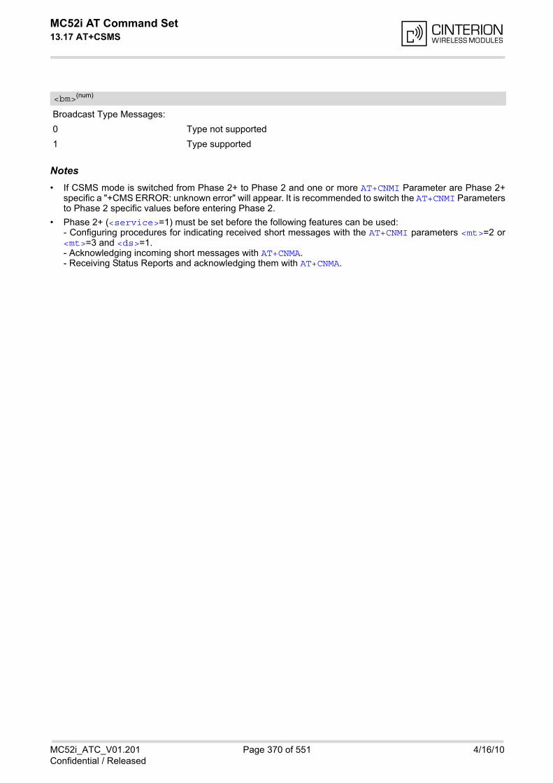
MC52i AT Command Set 13.17 AT+CSMS
MC52i_ATC_V01.201 Page 370 of 551 4/16/10Confidential / Released
Broadcast Type Messages:
0 Type not supported
1 Type supported
Notes• If CSMS mode is switched from Phase 2+ to Phase 2 and one or more AT+CNMI Parameter are Phase 2+
specific a "+CMS ERROR: unknown error" will appear. It is recommended to switch the AT+CNMI Parametersto Phase 2 specific values before entering Phase 2.
• Phase 2+ (<service>=1) must be set before the following features can be used: - Configuring procedures for indicating received short messages with the AT+CNMI parameters <mt>=2 or<mt>=3 and <ds>=1. - Acknowledging incoming short messages with AT+CNMA. - Receiving Status Reports and acknowledging them with AT+CNMA.
<bm>(num)
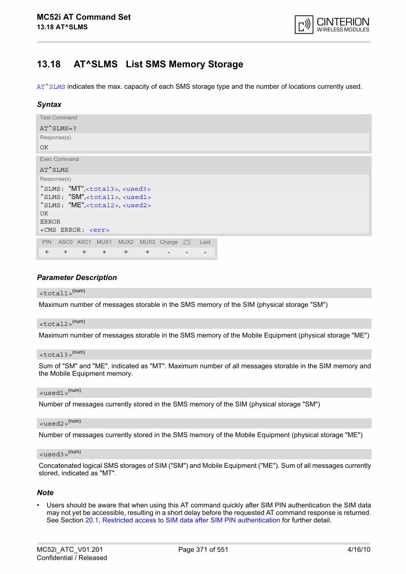
MC52i AT Command Set 13.18 AT^SLMS
MC52i_ATC_V01.201 Page 371 of 551 4/16/10Confidential / Released
13.18 AT^SLMS List SMS Memory Storage
AT^SLMS indicates the max. capacity of each SMS storage type and the number of locations currently used.
Syntax
Parameter Description
Maximum number of messages storable in the SMS memory of the SIM (physical storage "SM")
Maximum number of messages storable in the SMS memory of the Mobile Equipment (physical storage "ME")
Sum of "SM" and "ME", indicated as "MT". Maximum number of all messages storable in the SIM memory andthe Mobile Equipment memory.
Number of messages currently stored in the SMS memory of the SIM (physical storage "SM")
Number of messages currently stored in the SMS memory of the Mobile Equipment (physical storage "ME")
Concatenated logical SMS storages of SIM ("SM") and Mobile Equipment ("ME"). Sum of all messages currentlystored, indicated as "MT".
Note• Users should be aware that when using this AT command quickly after SIM PIN authentication the SIM data
may not yet be accessible, resulting in a short delay before the requested AT command response is returned.See Section 20.1, Restricted access to SIM data after SIM PIN authentication for further detail.
Test Command
AT^SLMS=?Response(s)
OK
Exec Command
AT^SLMSResponse(s)
^SLMS: ''MT'',<total3>, <used3>^SLMS: ''SM'',<total1>, <used1>^SLMS: ''ME'',<total2>, <used2>OKERROR+CMS ERROR: <err>
PIN ASC0 ASC1 MUX1 MUX2 MUX3 Charge Last
+ + + + + + - - -
<total1>(num)
<total2>(num)
<total3>(num)
<used1>(num)
<used2>(num)
<used3>(num)

MC52i AT Command Set 13.19 AT^SMGL
MC52i_ATC_V01.201 Page 372 of 551 4/16/10Confidential / Released
13.19 AT^SMGL List Short Messages from preferred store without set-ting status to REC READ
The write command allows to select a status type and lists, from the message storage <mem1>, all messagesthat currently have the specified <stat>. The major difference over the standard command AT+CMGL is that thestatus of the listed messages remains u n c h a n g e d (unread remains unread).The execute command is the same as the write command, but uses the given default of <stat>.
Syntax
Notes• The selected <mem1> can contain different types of SMs (e.g. SMS-DELIVERs, SMS-SUBMITs, SMS-STA-
TUS-REPORTs and SMS-COMMANDs), the response may be a mix of the responses of different SM types.TE application can recognize the response format by examining the third response parameter.
• Users should be aware that when using this AT command quickly after SIM PIN authentication the SIM datamay not yet be accessible, resulting in a short delay before the requested AT command response is returned.See Section 20.1, Restricted access to SIM data after SIM PIN authentication for further detail.
Test Command
AT^SMGL=?Response(s)
same as AT+CMGL
Exec Command
AT^SMGLResponse(s)
^SMGL: (For default values of <stat>, see "Section 13.1, SMS parameters.)OK
Write Command
AT^SMGL=<stat>Response(s)
same as AT+CMGL
PIN ASC0 ASC1 MUX1 MUX2 MUX3 Charge Last
+ + + + + + - - -
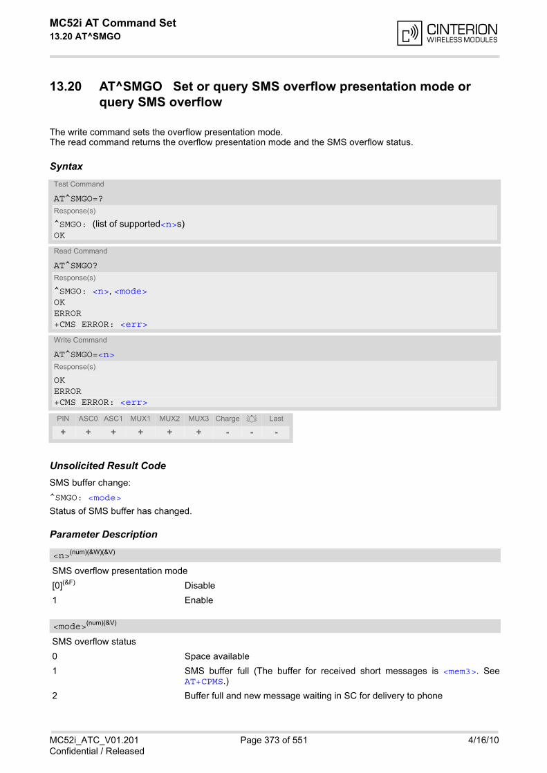
MC52i AT Command Set 13.20 AT^SMGO
MC52i_ATC_V01.201 Page 373 of 551 4/16/10Confidential / Released
13.20 AT^SMGO Set or query SMS overflow presentation mode or query SMS overflow
The write command sets the overflow presentation mode.The read command returns the overflow presentation mode and the SMS overflow status.
Syntax
Unsolicited Result CodeSMS buffer change:
^SMGO: <mode>
Status of SMS buffer has changed.
Parameter Description
SMS overflow presentation mode
[0](&F) Disable
1 Enable
SMS overflow status
0 Space available
1 SMS buffer full (The buffer for received short messages is <mem3>. SeeAT+CPMS.)
2 Buffer full and new message waiting in SC for delivery to phone
Test Command
AT^SMGO=?Response(s)
^SMGO: (list of supported<n>s)OK
Read Command
AT^SMGO?Response(s)
^SMGO: <n>, <mode>OKERROR+CMS ERROR: <err>
Write Command
AT^SMGO=<n>Response(s)
OKERROR+CMS ERROR: <err>
PIN ASC0 ASC1 MUX1 MUX2 MUX3 Charge Last
+ + + + + + - - -
<n>(num)(&W)(&V)
<mode>(num)(&V)

MC52i AT Command Set 13.20 AT^SMGO
MC52i_ATC_V01.201 Page 374 of 551 4/16/10Confidential / Released
Notes• Incoming short messages with message class 1 (ME specific short messages) or class 2 (SIM specific short
messages), see <dcs> in GSM 03.38, will be stored either in ''ME'' or in ''SM'' storage. Therefore the "^SMGO:2" indication could occur, without issuing the indication "^SMGO: 1" before. The indication "^SMGO: 1" meansthat both buffers (''ME'' and ''SM'') are full.
• For more information regarding SIM and ME specific message classes refer to <dcs> and the following spec-ifications: GSM 03.38 and 3GPP TS 23.038 .
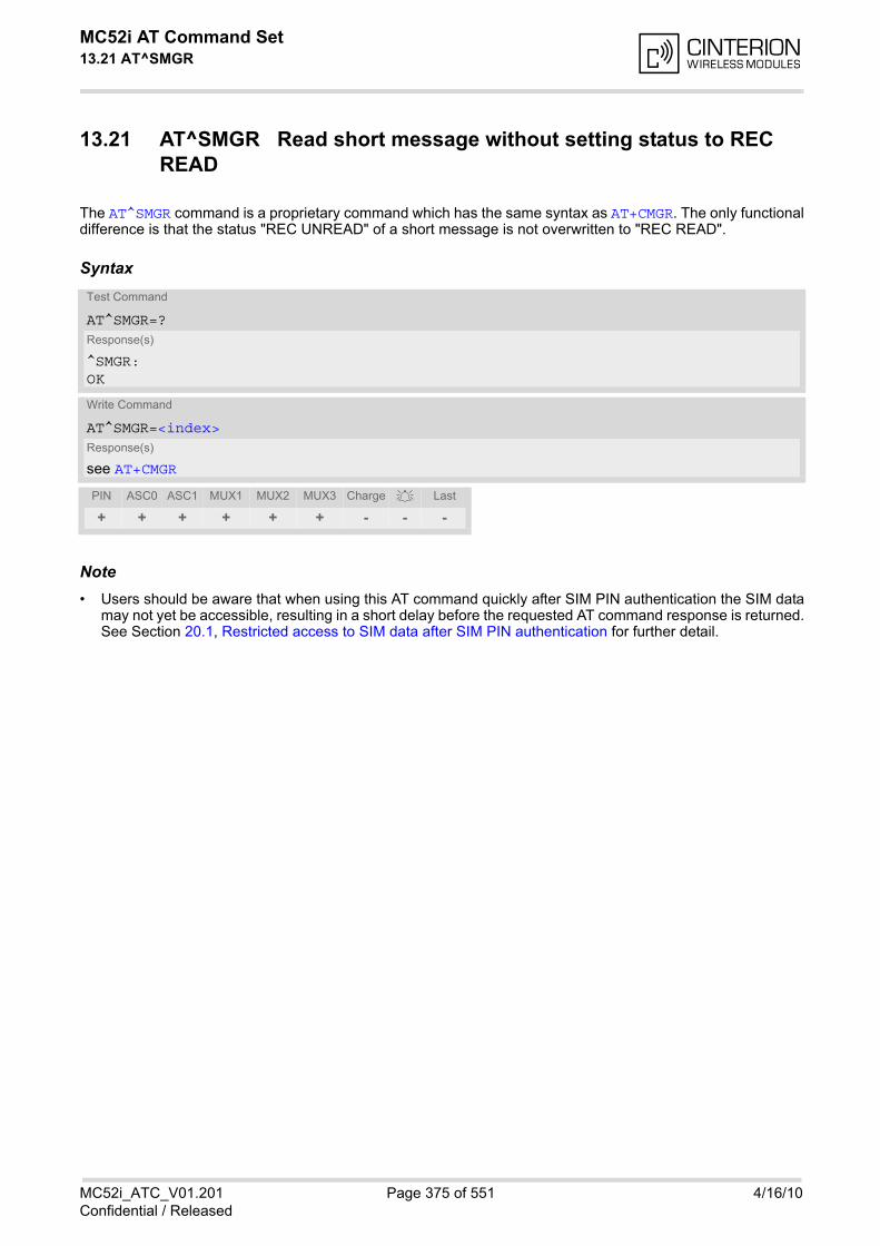
MC52i AT Command Set 13.21 AT^SMGR
MC52i_ATC_V01.201 Page 375 of 551 4/16/10Confidential / Released
13.21 AT^SMGR Read short message without setting status to REC READ
The AT^SMGR command is a proprietary command which has the same syntax as AT+CMGR. The only functionaldifference is that the status "REC UNREAD" of a short message is not overwritten to "REC READ".
Syntax
Note• Users should be aware that when using this AT command quickly after SIM PIN authentication the SIM data
may not yet be accessible, resulting in a short delay before the requested AT command response is returned.See Section 20.1, Restricted access to SIM data after SIM PIN authentication for further detail.
Test Command
AT^SMGR=?Response(s)
^SMGR: OK
Write Command
AT^SMGR=<index>Response(s)
see AT+CMGR
PIN ASC0 ASC1 MUX1 MUX2 MUX3 Charge Last
+ + + + + + - - -
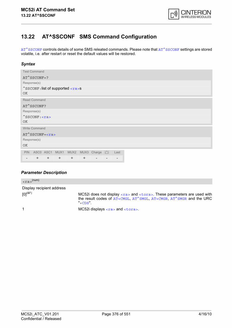
MC52i AT Command Set 13.22 AT^SSCONF
MC52i_ATC_V01.201 Page 376 of 551 4/16/10Confidential / Released
13.22 AT^SSCONF SMS Command Configuration
AT^SSCONF controls details of some SMS releated commands. Please note that AT^SSCONF settings are storedvolatile, i.e. after restart or reset the default values will be restored.
Syntax
Parameter Description
Display recipient address
[0](&F) MC52i does not display <ra> and <tora>. These parameters are used withthe result codes of AT+CMGL, AT^SMGL, AT+CMGR, AT^SMGR and the URC"+CDS".
1 MC52i displays <ra> and <tora>.
Test Command
AT^SSCONF=?Response(s)
^SSCONF:list of supported <ra>s OK
Read Command
AT^SSCONF?Response(s)
^SSCONF:<ra>OK
Write Command
AT^SSCONF=<ra>Response(s)
OK
PIN ASC0 ASC1 MUX1 MUX2 MUX3 Charge Last
- + + + + + - - -
<ra>(num)

MC52i AT Command Set 13.23 AT^SSDA
MC52i_ATC_V01.201 Page 377 of 551 4/16/10Confidential / Released
13.23 AT^SSDA Set SMS Display Availability
This command allows to notify the MC52i of its controlling application's capability to immediately display incom-ing SMS on a display. If the application is able to display incoming short messages, a class 0 message shall be displayed immediately.However, if it does not, class 0 messages shall be treated as if no message class is determined (GSM 03.38[17]). The effect of this command if <da>=1 is to determine the behavior of parameter <mt> of AT+CNMI: If <da>=1 and <mt>=1 incoming class 0 mesages need to be acknowledged with AT+CNMA (see also AT+CNMIand AT+CSMS) If multiplex mode is enabled (AT+CMUX) and <da>=1 with <mt>=1 is set on any logical channel, all other chan-nels have to use <mt>=0.
Syntax
Parameter Description
Display Availability
0(&F) Application is not able to display incoming short message
1 Application is able to display incoming short message
Note• If the ME operates on different instances (MUX channels 1, 2, 3 or ASC0/ASC1) avoid different settings for
routing and indicating short messages. For example, if messages shall be routed directly to one instance ofthe TE (set with AT+CNMI, AT^SSDA), it is not possible to activate the presentation of URCs with AT+CMERor AT+CNMI on another instance. Any attempt to activate settings that conflict with existing settings onanother interface, will result in "+CME ERROR", or accordingly "+CMS ERROR".
Test Command
AT^SSDA=?Response(s)
^SSDA:list of supported <da>s OK
Read Command
AT^SSDA?Response(s)
^SSDA:<da>OK
Write Command
AT^SSDA=<da>Response(s)
OK
PIN ASC0 ASC1 MUX1 MUX2 MUX3 Charge Last
- + + + + + - - -
<da>(num)
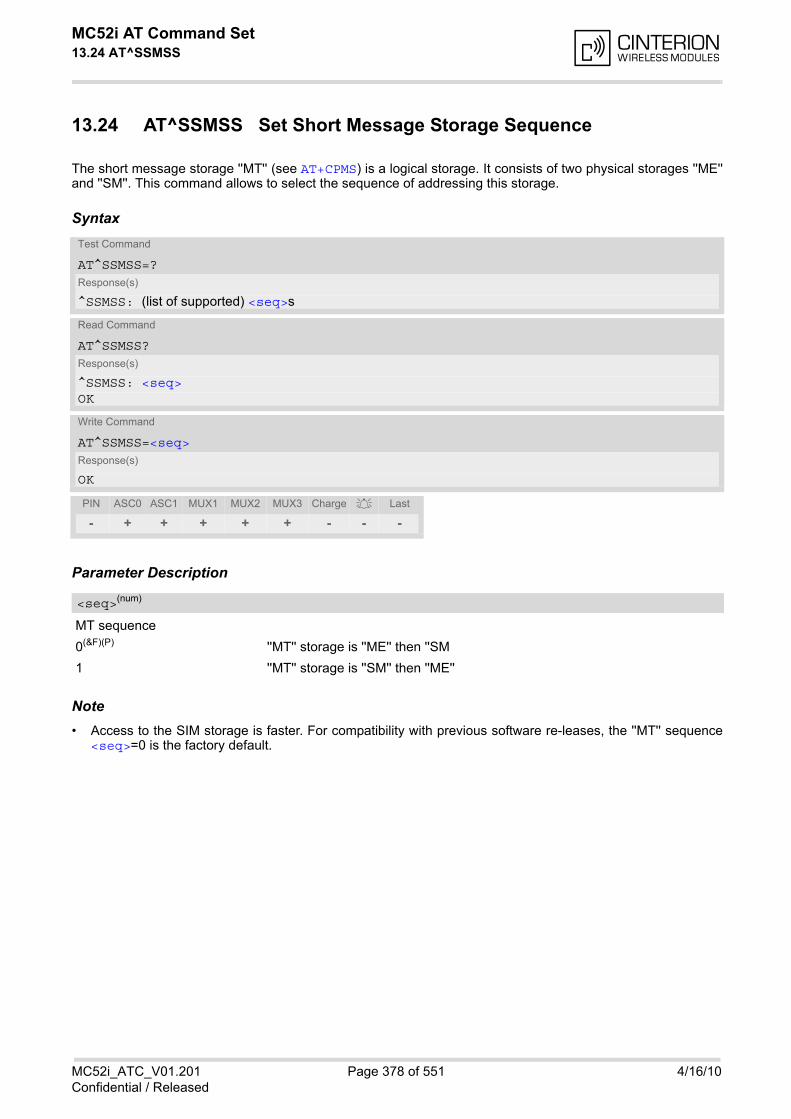
MC52i AT Command Set 13.24 AT^SSMSS
MC52i_ATC_V01.201 Page 378 of 551 4/16/10Confidential / Released
13.24 AT^SSMSS Set Short Message Storage Sequence
The short message storage ''MT'' (see AT+CPMS) is a logical storage. It consists of two physical storages ''ME''and ''SM''. This command allows to select the sequence of addressing this storage.
Syntax
Parameter Description
MT sequence
0(&F)(P) ''MT'' storage is ''ME'' then ''SM
1 ''MT'' storage is ''SM'' then ''ME''
Note• Access to the SIM storage is faster. For compatibility with previous software re-leases, the ''MT'' sequence
<seq>=0 is the factory default.
Test Command
AT^SSMSS=?Response(s)
^SSMSS: (list of supported) <seq>s
Read Command
AT^SSMSS?Response(s)
^SSMSS: <seq>OK
Write Command
AT^SSMSS=<seq>Response(s)
OK
PIN ASC0 ASC1 MUX1 MUX2 MUX3 Charge Last
- + + + + + - - -
<seq>(num)
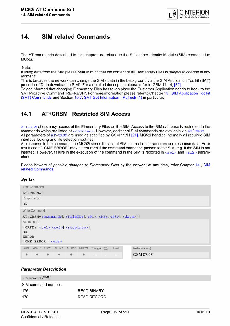
MC52i AT Command Set 14. SIM related Commands
MC52i_ATC_V01.201 Page 379 of 551 4/16/10Confidential / Released
14. SIM related Commands
The AT commands described in this chapter are related to the Subscriber Identity Module (SIM) connected toMC52i.
Note:If using data from the SIM please bear in mind that the content of all Elementary Files is subject to change at anymoment!This is because the network can change the SIM's data in the background via the SIM Application Toolkit (SAT)procedure "Data download to SIM". For a detailed description please refer to GSM 11.14, [22]. To get informed that changing Elementary Files has taken place the Customer Application needs to hook to theSAT Proactive Command "REFRESH". For more information please refer to Chapter 15., SIM Application Toolkit(SAT) Commands and Section 15.7, SAT Get Information - Refresh (1) in particular.
14.1 AT+CRSM Restricted SIM Access
AT+CRSM offers easy access of the Elementary Files on the SIM. Access to the SIM database is restricted to thecommands which are listed at <command>. However, additional SIM commands are available via AT^SXSM. All parameters of AT+CRSM are used as specified by GSM 11.11 [21]. MC52i handles internally all required SIMinterface locking and file selection routines. As response to the command, the MC52i sends the actual SIM information parameters and response data. Errorresult code "+CME ERROR" may be returned if the command cannot be passed to the SIM, e.g. if the SIM is notinserted. However, failure in the execution of the command in the SIM is reported in <sw1> and <sw2> param-eters.
Please beware of possible changes to Elementary Files by the network at any time, refer Chapter 14., SIMrelated Commands.
Syntax
Parameter Description
SIM command number.
176 READ BINARY
178 READ RECORD
Test Command
AT+CRSM=?Response(s)
OK
Write Command
AT+CRSM=<command>[, <fileID>[, <P1>, <P2>, <P3>[, <data>]]]Response(s)
+CRSM: <sw1>,<sw2>[,<response>] OK ERROR +CME ERROR: <err>
PIN ASC0 ASC1 MUX1 MUX2 MUX3 Charge Last Reference(s)
+ + + + + + - - - GSM 07.07
<command>(num)
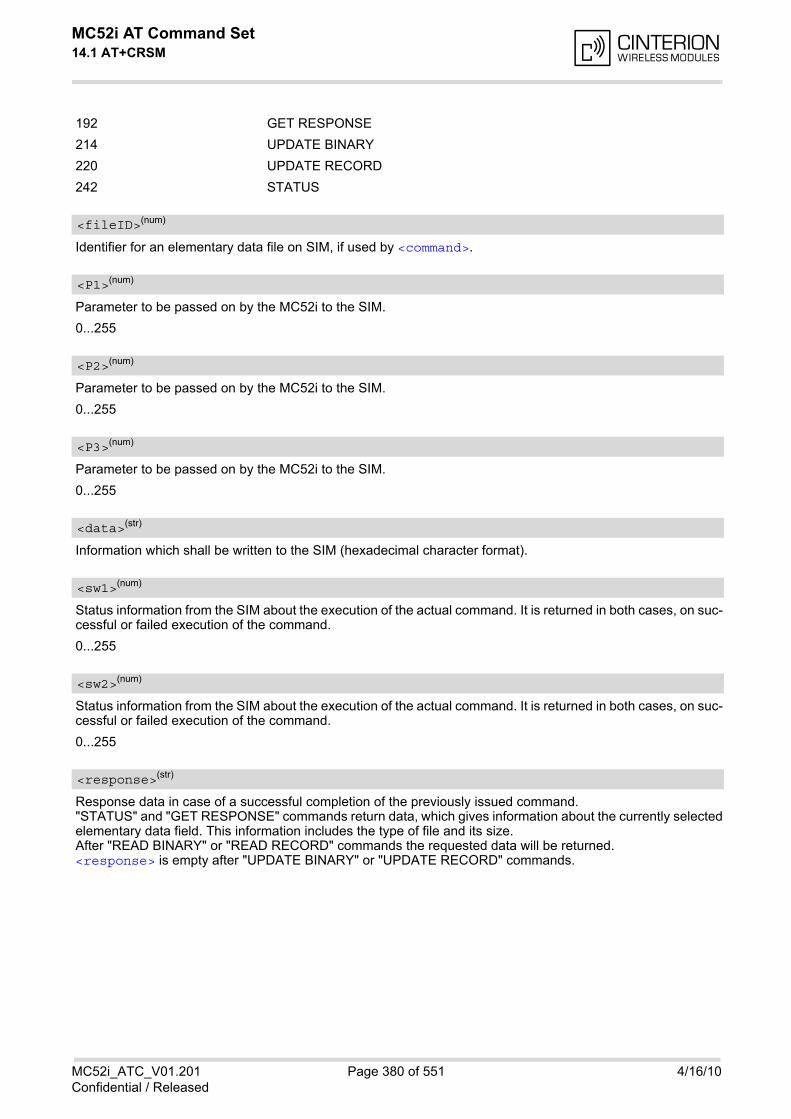
MC52i AT Command Set 14.1 AT+CRSM
MC52i_ATC_V01.201 Page 380 of 551 4/16/10Confidential / Released
192 GET RESPONSE
214 UPDATE BINARY
220 UPDATE RECORD
242 STATUS
Identifier for an elementary data file on SIM, if used by <command>.
Parameter to be passed on by the MC52i to the SIM.
0...255
Parameter to be passed on by the MC52i to the SIM.
0...255
Parameter to be passed on by the MC52i to the SIM.
0...255
Information which shall be written to the SIM (hexadecimal character format).
Status information from the SIM about the execution of the actual command. It is returned in both cases, on suc-cessful or failed execution of the command.
0...255
Status information from the SIM about the execution of the actual command. It is returned in both cases, on suc-cessful or failed execution of the command.
0...255
Response data in case of a successful completion of the previously issued command. "STATUS" and "GET RESPONSE" commands return data, which gives information about the currently selectedelementary data field. This information includes the type of file and its size. After "READ BINARY" or "READ RECORD" commands the requested data will be returned. <response> is empty after "UPDATE BINARY" or "UPDATE RECORD" commands.
<fileID>(num)
<P1>(num)
<P2>(num)
<P3>(num)
<data>(str)
<sw1>(num)
<sw2>(num)
<response>(str)
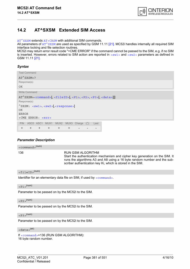
MC52i AT Command Set 14.2 AT^SXSM
MC52i_ATC_V01.201 Page 381 of 551 4/16/10Confidential / Released
14.2 AT^SXSM Extended SIM Access
AT^SXSM extends AT+CRSM with additional SIM commands. All parameters of AT^SXSM are used as specified by GSM 11.11 [21]. MC52i handles internally all required SIMinterface locking and file selection routines. MC52i may return error result code "+CME ERROR" if the command cannot be passed to the SIM, e.g. if no SIMis inserted. However, errors related to SIM action are reported in <sw1> and <sw2> parameters as defined inGSM 11.11 [21].
Syntax
Parameter Description
136 RUN GSM ALGORITHM Start the authentication mechanism and cipher key generation on the SIM. Itruns the algorithms A3 and A8 using a 16 byte random number and the sub-scriber authentication key Ki, which is stored in the SIM.
Identifier for an elementary data file on SIM, if used by <command>.
Parameter to be passed on by the MC52i to the SIM.
Parameter to be passed on by the MC52i to the SIM.
Parameter to be passed on by the MC52i to the SIM.
If <command>=136 (RUN GSM ALGORITHM): 16 byte random number.
Test Command
AT^SXSM=?Response(s)
OK
Write Command
AT^SXSM=<command>[, <fileID>[, <P1>, <P2>, <P3>[, <data>]]]Response(s)
^SXSM: <sw1>, <sw2>[,<response>] OK ERROR +CME ERROR: <err>
PIN ASC0 ASC1 MUX1 MUX2 MUX3 Charge Last
+ + + + + + - - -
<command>(num)
<fileID>(num)
<P1>(num)
<P2>(num)
<P3>(num)
<data>(str)
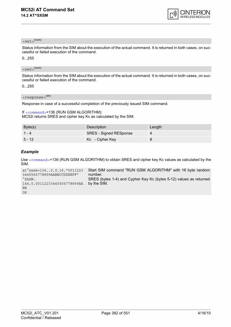
MC52i AT Command Set 14.2 AT^SXSM
MC52i_ATC_V01.201 Page 382 of 551 4/16/10Confidential / Released
Status information from the SIM about the execution of the actual command. It is returned in both cases, on suc-cessful or failed execution of the command.
0...255
Status information from the SIM about the execution of the actual command. It is returned in both cases, on suc-cessful or failed execution of the command.
0...255
Response in case of a successful completion of the previously issued SIM command.
If <command>=136 (RUN GSM ALGORITHM): MC52i returns SRES and cipher key Kc as calculated by the SIM.
Example
Use <command>=136 (RUN GSM ALGORITHM) to obtain SRES and cipher key Kc values as calculated by theSIM.
<sw1>(num)
<sw2>(num)
<response>(str)
Byte(s) Description Length
1 - 4 SRES - Signed RESponse 4
5 - 12 Kc - Cipher Key 8
at^sxsm=136,,0,0,16,"00112233445566778899AABBCCDDEEFF"
Start SIM command "RUN GSM ALGORITHM" with 16 byte randomnumber.
^SXSM: 144,0,00112233445566778899AABB
SRES (bytes 1-4) and Cypher Key Kc (bytes 5-12) values as returnedby the SIM.
OK

MC52i AT Command Set 14.3 AT^SCKS
MC52i_ATC_V01.201 Page 383 of 551 4/16/10Confidential / Released
14.3 AT^SCKS Query SIM and Chip Card Holder Status
This command controls the SIM connection presentation mode and queries the connection status of the SIM andthe card holder tray of the MC52i.
Syntax
Unsolicited Result Code^SCKS: <SimStatus>
If the SIM connection status has changed an unsolicited result code (URC) is issued.
Parameter Description
0(&F) Suppress unsolicited result codes
1 Output unsolicited result codes
0 Card holder tray removed or SIM connection error
1 SIM inserted (refer to note)
Note• <SimStatus> reflects the status of the SIM and the card holder tray. Therefore if an empty SIM card holder
tray is inserted, two URCs will be presented, indicating the status 1 followed by 0. See example.
Test Command
AT^SCKS=?Response(s)
^SCKS:(list of supported <mode>s)OK
Read Command
AT^SCKS?Response(s)
^SCKS: <mode>, <SimStatus>OKERROR+CME ERROR: <err>
Write Command
AT^SCKS=<mode>Response(s)
OKERROR+CME ERROR: <err>
PIN ASC0 ASC1 MUX1 MUX2 MUX3 Charge Last
- + + + + + - - -
<mode>(num)(&W)(&V)
<SimStatus>(num)(&V)
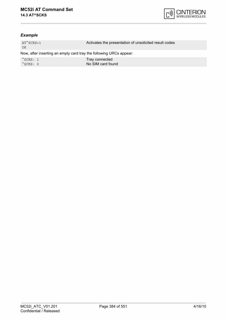
MC52i AT Command Set 14.3 AT^SCKS
MC52i_ATC_V01.201 Page 384 of 551 4/16/10Confidential / Released
Example
Now, after inserting an empty card tray the following URCs appear:
AT^SCKS=1 Activates the presentation of unsolicited result codesOK
^SCKS: 1 Tray connected^SCKS: 0 No SIM card found
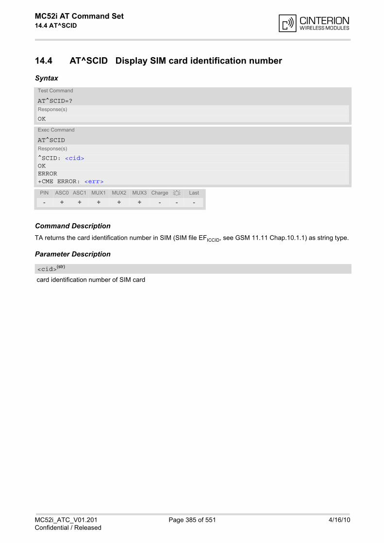
MC52i AT Command Set 14.4 AT^SCID
MC52i_ATC_V01.201 Page 385 of 551 4/16/10Confidential / Released
14.4 AT^SCID Display SIM card identification number
Syntax
Command DescriptionTA returns the card identification number in SIM (SIM file EFICCID, see GSM 11.11 Chap.10.1.1) as string type.
Parameter Description
card identification number of SIM card
Test Command
AT^SCID=?Response(s)
OK
Exec Command
AT^SCIDResponse(s)
^SCID: <cid>OKERROR+CME ERROR: <err>
PIN ASC0 ASC1 MUX1 MUX2 MUX3 Charge Last
- + + + + + - - -
<cid>(str)
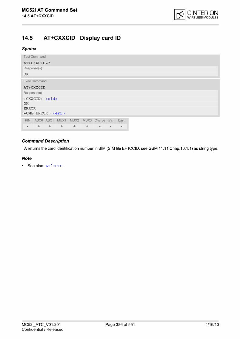
MC52i AT Command Set 14.5 AT+CXXCID
MC52i_ATC_V01.201 Page 386 of 551 4/16/10Confidential / Released
14.5 AT+CXXCID Display card ID
Syntax
Command DescriptionTA returns the card identification number in SIM (SIM file EF ICCID, see GSM 11.11 Chap.10.1.1) as string type.
Note• See also: AT^SCID.
Test Command
AT+CXXCID=?Response(s)
OK
Exec Command
AT+CXXCIDResponse(s)
+CXXCID: <cid>OKERROR+CME ERROR: <err>
PIN ASC0 ASC1 MUX1 MUX2 MUX3 Charge Last
- + + + + + - - -
MC52i AT Command Set 15. SIM Application Toolkit (SAT) Commands
MC52i_ATC_V01.201 Page 387 of 551 4/16/10Confidential / Released
15. SIM Application Toolkit (SAT) Commands
This chapter describes AT commands and responses related to the MC52i's SIM Application Toolkit (SAT) imple-mentation.
3GPP document GSM 11.14 [22] specifies SAT in detail.
SIM Application Toolkit (SAT) is a technology that allows an application running on the SIM to control the GSMMobile Engine (ME). Remote-SAT (RSAT) provides a link between applications located on the SIM and a Cus-tomer Application (TE). The purpose of Remote-SAT is to allow the TE to send AT commands to the SAT inter-face and to display all SAT activities on the user interface of the Customer Application. The overall scenario isillustrated in the context diagram below.
Two groups of commands are exchanged between the SAT located on the MC52i and the SIM Application run-ning on the SIM:
• Proactive commands are sent from the SIM application to the MC52i's SAT, such as "DISPLAY TEXT".
• Envelope commands are sent from the MC52i's SAT to the SIM application, such as "MENU SELECTION".
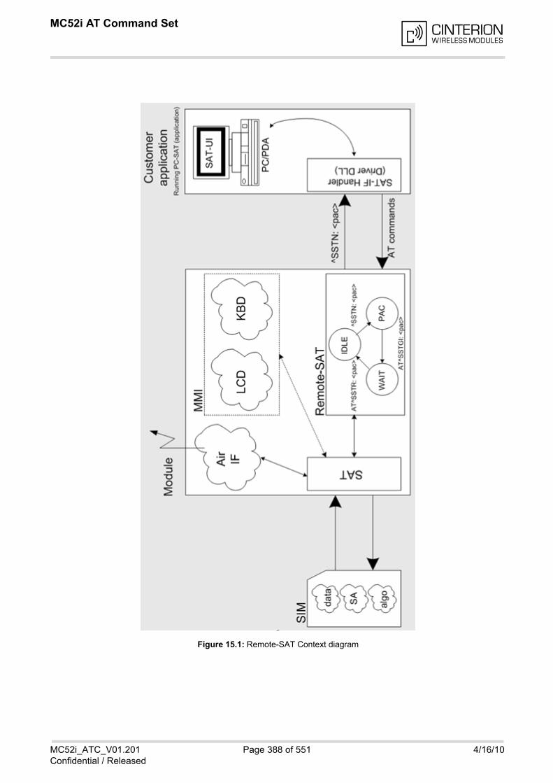
MC52i AT Command Set
MC52i_ATC_V01.201 Page 388 of 551 4/16/10Confidential / Released
Figure 15.1: Remote-SAT Context diagram
MC52i AT Command Set 15.1 Usage of Remote-SAT
MC52i_ATC_V01.201 Page 389 of 551 4/16/10Confidential / Released
15.1 Usage of Remote-SAT
If SAT functionality is delivered by the SIM provider, the related SAT commands have to be handled. Otherwiseother SIM functionality may not working correctly (e.g. SMS-PP downloads).Therefore two possible modes are available.
15.1.1 Automatic Response Mode (AR Mode)
If the ME operates in this (default) mode, usage of any Remote-Sat AT commands is not necessary. In this case,all commands and responses are exchanged automatically between the ME and the SIM application. The typeof Terminal Response (TR) to a SAT Proactive Command issued by the SIM application used in AR mode islisted in Table 15.6, Command Type Table, column "Auto Terminal Response".To take full advantage of Remote-SAT the ER mode has to be enabled using AT^SSTA=1. This setting is storednon-volatile and takes effect after next switch-on of the ME.
15.1.2 Explicit Response Mode (ER Mode)
As a Wireless Modem does not have an MMI, Remote-SAT differs from a phone implementation of SAT. It usesa special set of AT commands to pass data, e.g. a list of menu items, to the TE and to receive responses, e.g. aselected menu item.The TE is required to monitor the status of an ongoing SAT Proactive Command (PAC) and, if required, sendsappropriate AT commands, depending upon users input.
15.1.3 Character Sets
Strings are passed as UCS2 characters, but using the GSM alphabet is also possible. Use of GSM alphabet isnot recommended since a SIM can contain text which might be not displayable, e.g. greek characters. UseAT^SSTA command to select the type of alphabet both for input and output. UCS is specified in ISO/IEC 10646.There are 2 and 4 octet versions available, of which only the 2-octet variant is used, known as UCS2. The 65536positions in the 2-octet form of UCS are divided into 256 rows, each with 256 cells. The first octet of a characterrepresentation gives the row number, the second the cell number. The first row, row 0, contains exactly the samecharacters as ISO/IEC 8859-1. The first 128 characters are thus the ASCII characters. The octet representingan ISO/IEC 8859-1 character is easily transformed to the representation in UCS by putting a 0 octet in front of it.UCS includes the same control characters as ISO/IEC 8859 which are located in row 0.
15.1.4 SIM Update Initiated by the Network
If the Customer Application uses data of the SIM card please consider that the contents of all elementary filesare subject to change at any time. This happens because the network can change the SIM card data in the back-ground via the SIM Application Toolkit (SAT) procedure "Data download to SIM". For a detailed description referto GSM 11.14. In order to receive the information that an elementary file has been changed the TE has to activateRemote SAT and needs to look for the SAT Proactive Command "REFRESH", Section 15.7, SAT Get Informa-tion - Refresh (1).
15.1.5 Icon Handling
Several SAT Proactive commands may provide an icon identifier. Icons are intended to enhance the MMI by pro-viding graphical information to the user. The display of icons is optional for the ME.The SIM indicates to the ME whether the icon replaces an alpha identifier or text string, or whether it accompa-nies it (icon qualifier).
MC52i AT Command Set 15.1 Usage of Remote-SAT
MC52i_ATC_V01.201 Page 390 of 551 4/16/10Confidential / Released
If both an alpha identifier or text string, and an icon are provided with a proactive command, and both arerequested to be displayed, but the ME is not able to display both together on the screen, then the alpha identifieror text string takes precedence over the icon.
If the SIM provides an icon identifier with a proactive command, then the ME shall inform the SIM if the icon couldnot be displayed by sending the response "Command performed successfully, but requested icon could not bedisplayed" (via AT^SSTR).
The icon data can be fetched directly from the SIM via command AT+CRSM, for details please refer to GSM11.11, Annex G. The icon data can be read from the SIM on system start then cached.
15.1.6 Using SMS Related AT Commands
ME activities triggered by SAT often end in sending or receiving short messages. Usually, a short message con-taining a service request is sent to the network, for example a request to send the latest news. Subsequently,the network returns a short message containing the requested information. This short message needs to be readby the application running on the TE.
Set SMS text modeAT+CMGF=1
Activate the display of a URC on every received SMSAT+CNMI=1,1
If needed activate extended SMS text mode parameter outputAT+CSDH=1This is useful in order to obtain more detailed header information along with the incoming SMS (e.g. SMS class).Please refer to 3GPP standard GSM 03.38 for details.As a result, a URC will be output each time a short message is received+CMTI: "MT", 1 where• the first parameter "MT" specifies the storage type of the SMS• the second parameter contains a unique location number.In the given example, the short message was stored to the memory type "MT" at location number 1.The short message storage "MT" is a logical storage. It is the sum of the two physical storages "ME" (MobileEquipment message storage) and "SM" (SIM message storage). For more detailed information please refer to[1], particularly AT+CPMS and AT^SSMSS.
To read the SMS data useAT+CMGR=<location>where <location> is the location number of the received SMS, e.g. 1 in the example above.
To list all stored short messages useAT+CMGL="ALL"
To delete a certain SMS after reading useAT+CMGD=<location>
MC52i AT Command Set 15.2 Remote-SAT States
MC52i_ATC_V01.201 Page 391 of 551 4/16/10Confidential / Released
15.2 Remote-SAT States
In order to communicate with the SIM Application Toolkit it is necessary to use AT commands which areexplained in detail in the following chapters. In general, the type of AT command which should be issued dependson the current state of the Remote-SAT interface. The current state of Remote-SAT is determined by
1. the Remote-SAT operating mode (AR or ER mode),
2. the application running on the SIM,
3. the Customer Application (in case of ER mode only), and
4. internal actions of the ME (especially SAT and Call Control).
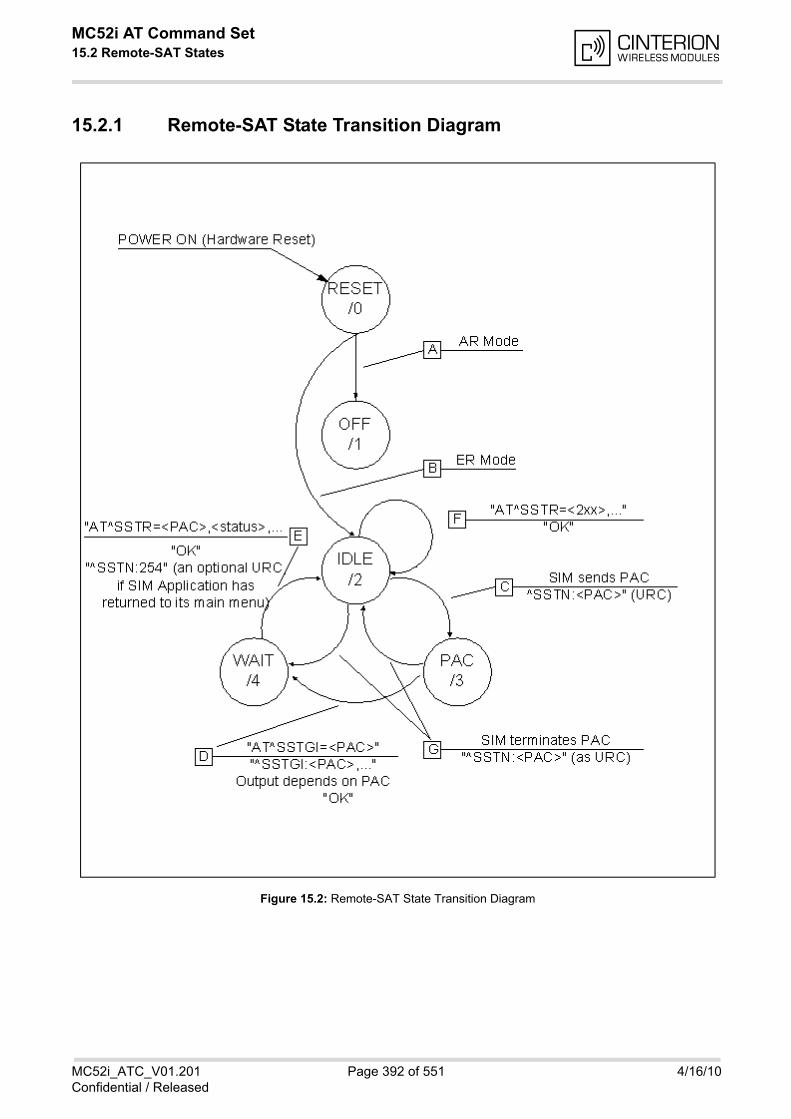
MC52i AT Command Set 15.2 Remote-SAT States
MC52i_ATC_V01.201 Page 392 of 551 4/16/10Confidential / Released
15.2.1 Remote-SAT State Transition Diagram
Figure 15.2: Remote-SAT State Transition Diagram

MC52i AT Command Set 15.2 Remote-SAT States
MC52i_ATC_V01.201 Page 393 of 551 4/16/10Confidential / Released
15.2.2 Remote-SAT State Transition Table
The following table outlines which AT commands can be issued during certain states. However, the test and readAT commands are available at any time. This way it is possible to determine the current state of the interface viaAT^SSTA?.
Meaning of options usable in column "M/O/X" of the following tables:M: The TE has to issue the AT command to get Remote-SAT service (mandatory).O: Usage of AT command is optional.X: Usage of AT command is not allowed or not useful at this time and may cause an error message.
Table 15.1: State: RESET description
Table 15.2: State: OFF description
Table 15.3: State: IDLE description
RESET: State after power on the ME.
AT command M/O/X Description
^SSTA=0,n O Enable AR Mode (with alphabet type <n>)
^SSTA=1,n O Enable ER Mode (with alphabet type <n>)
^SSTGI=<pac> X
^SSTR=<pac> X
^SSTR=<event> X
OFF: ME is in Auto Response Mode.
AT command M/O/X Description
^SSTA=0,n O Enable AR Mode (with alphabet type <n>)
^SSTA=1,n O Enable ER Mode (with alphabet type <n>)
^SSTGI=<pac> X
^SSTR=<pac> X
^SSTR=<event> X
IDLE: ME is in Explicit Response Mode.
AT command M/O/X Description
^SSTA=0,n O Enable AR Mode (with alphabet type <n>)
^SSTA=1,n O Enable ER Mode (with alphabet type <n>)
^SSTGI=<pac> O Show PAC information
^SSTR=<pac> X
^SSTR=<event> O
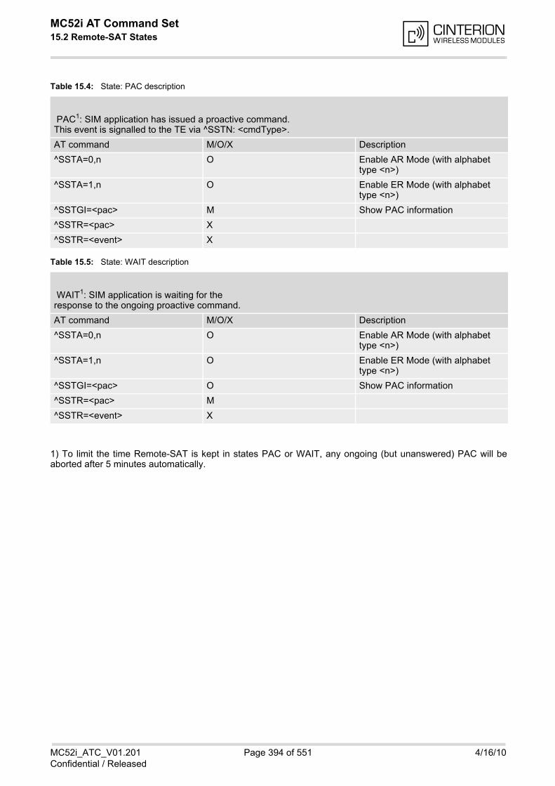
MC52i AT Command Set 15.2 Remote-SAT States
MC52i_ATC_V01.201 Page 394 of 551 4/16/10Confidential / Released
Table 15.4: State: PAC description
Table 15.5: State: WAIT description
1) To limit the time Remote-SAT is kept in states PAC or WAIT, any ongoing (but unanswered) PAC will beaborted after 5 minutes automatically.
PAC1: SIM application has issued a proactive command.This event is signalled to the TE via ^SSTN: <cmdType>.
AT command M/O/X Description
^SSTA=0,n O Enable AR Mode (with alphabet type <n>)
^SSTA=1,n O Enable ER Mode (with alphabet type <n>)
^SSTGI=<pac> M Show PAC information
^SSTR=<pac> X
^SSTR=<event> X
WAIT1: SIM application is waiting for theresponse to the ongoing proactive command.
AT command M/O/X Description
^SSTA=0,n O Enable AR Mode (with alphabet type <n>)
^SSTA=1,n O Enable ER Mode (with alphabet type <n>)
^SSTGI=<pac> O Show PAC information
^SSTR=<pac> M
^SSTR=<event> X
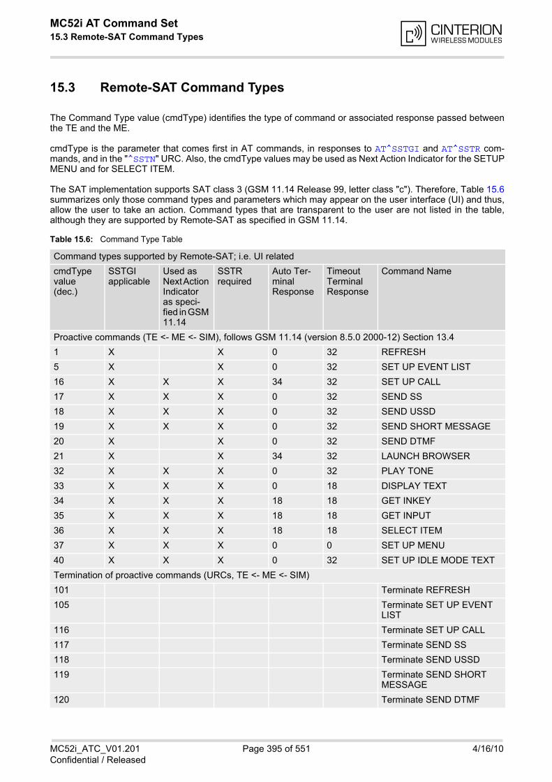
MC52i AT Command Set 15.3 Remote-SAT Command Types
MC52i_ATC_V01.201 Page 395 of 551 4/16/10Confidential / Released
15.3 Remote-SAT Command Types
The Command Type value (cmdType) identifies the type of command or associated response passed betweenthe TE and the ME.
cmdType is the parameter that comes first in AT commands, in responses to AT^SSTGI and AT^SSTR com-mands, and in the "^SSTN" URC. Also, the cmdType values may be used as Next Action Indicator for the SETUPMENU and for SELECT ITEM.
The SAT implementation supports SAT class 3 (GSM 11.14 Release 99, letter class "c"). Therefore, Table 15.6summarizes only those command types and parameters which may appear on the user interface (UI) and thus,allow the user to take an action. Command types that are transparent to the user are not listed in the table,although they are supported by Remote-SAT as specified in GSM 11.14.
Table 15.6: Command Type Table
Command types supported by Remote-SAT; i.e. UI related
cmdType value (dec.)
SSTGI applicable
Used as Next Action Indicator as speci-fied in GSM 11.14
SSTR required
Auto Ter-minal Response
Timeout Terminal Response
Command Name
Proactive commands (TE <- ME <- SIM), follows GSM 11.14 (version 8.5.0 2000-12) Section 13.4
1 X X 0 32 REFRESH
5 X X 0 32 SET UP EVENT LIST
16 X X X 34 32 SET UP CALL
17 X X X 0 32 SEND SS
18 X X X 0 32 SEND USSD
19 X X X 0 32 SEND SHORT MESSAGE
20 X X 0 32 SEND DTMF
21 X X 34 32 LAUNCH BROWSER
32 X X X 0 32 PLAY TONE
33 X X X 0 18 DISPLAY TEXT
34 X X X 18 18 GET INKEY
35 X X X 18 18 GET INPUT
36 X X X 18 18 SELECT ITEM
37 X X X 0 0 SET UP MENU
40 X X X 0 32 SET UP IDLE MODE TEXT
Termination of proactive commands (URCs, TE <- ME <- SIM)
101 Terminate REFRESH
105 Terminate SET UP EVENT LIST
116 Terminate SET UP CALL
117 Terminate SEND SS
118 Terminate SEND USSD
119 Terminate SEND SHORT MESSAGE
120 Terminate SEND DTMF
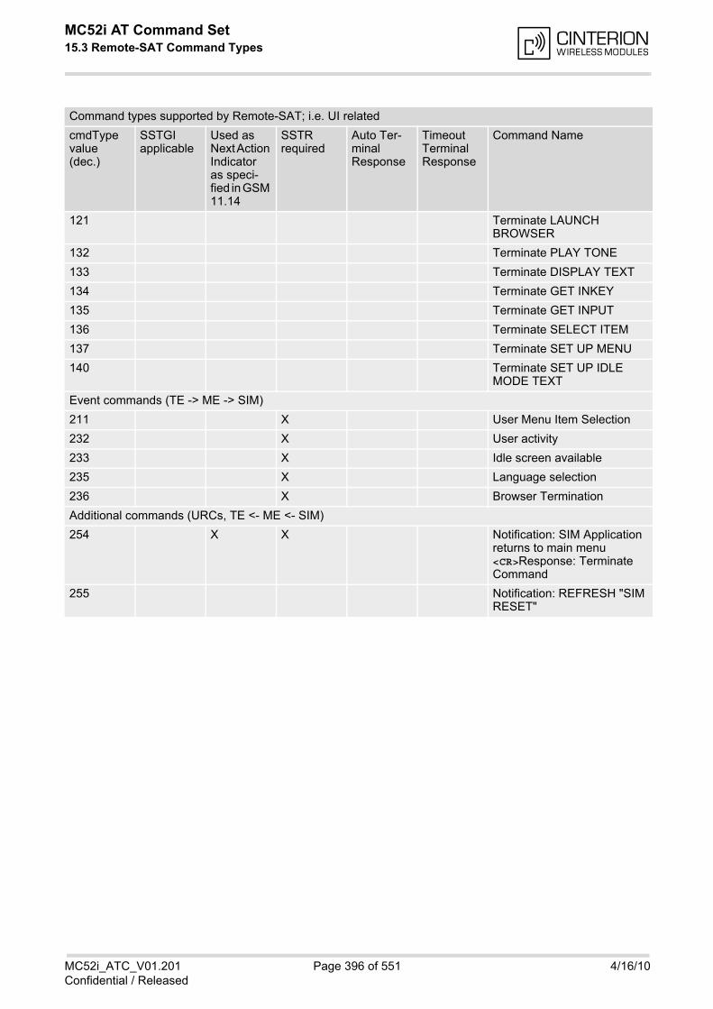
MC52i AT Command Set 15.3 Remote-SAT Command Types
MC52i_ATC_V01.201 Page 396 of 551 4/16/10Confidential / Released
121 Terminate LAUNCH BROWSER
132 Terminate PLAY TONE
133 Terminate DISPLAY TEXT
134 Terminate GET INKEY
135 Terminate GET INPUT
136 Terminate SELECT ITEM
137 Terminate SET UP MENU
140 Terminate SET UP IDLE MODE TEXT
Event commands (TE -> ME -> SIM)
211 X User Menu Item Selection
232 X User activity
233 X Idle screen available
235 X Language selection
236 X Browser Termination
Additional commands (URCs, TE <- ME <- SIM)
254 X X Notification: SIM Application returns to main menu <CR>Response: Terminate Command
255 Notification: REFRESH "SIM RESET"
Command types supported by Remote-SAT; i.e. UI related
cmdType value (dec.)
SSTGI applicable
Used as Next Action Indicator as speci-fied in GSM 11.14
SSTR required
Auto Ter-minal Response
Timeout Terminal Response
Command Name

MC52i AT Command Set 15.4 AT^SSTA
MC52i_ATC_V01.201 Page 397 of 551 4/16/10Confidential / Released
15.4 AT^SSTA SAT Interface Activation
The AT^SSTA write command can be used to specify the Remote-SAT activation mode <mode> and, if ExplicitResponse mode is enabled, to explicitly activate the Remote SAT interface. Removing and inserting the SIMdoes not affect the activation status.SAT commands which are not using the AT interface (non-MMI related SAT commands, e.g. PROVIDE LOCALINFORMATION) are executed without activating Remote-SAT.The read command can be used to request the current operating status and the used alphabet of the Remote-SAT interface.
Syntax
Parameter Description
MC52i Remote-SAT interface states
0 RESET
1 OFF
2 IDLE
3 PAC
4 WAIT
Parameter is stored non-volatile and takes effect after next restart of the ME.
0(D) GSM character setInput of a character requests one byte, e.g. "Y".
1 UCS2To display the 16 bit value of characters represented in UCS2 alphabet a 4 bytestring is required, e.g. "0059" is coding the character "Y". For details pleaserefer to ISO/IEC 10646.
Test Command
AT^SSTA=?Response(s)
^SSTA:(list of supported <state>s), (list of supported <Alphabet>s)OK
Read Command
AT^SSTA?Response(s)
^SSTA: <state>, <Alphabet>, <allowedInstance>, <SatProfile>OK
Write Command
AT^SSTA=<mode>[, <Alphabet>]Response(s)
OK
PIN ASC0 ASC1 MUX1 MUX2 MUX3 Charge Last Reference(s)
- + + + + + - - - CINTERION
<state>(num)
<Alphabet>(num)
MC52i AT Command Set 15.4 AT^SSTA
MC52i_ATC_V01.201 Page 398 of 551 4/16/10Confidential / Released
The whole RSAT handling (^SSTN, AT^SSTGI, AT^SSTR will only be active at the Instance, for which the SSTAcommand was executed.However, if the Instance should be changed, please execute AT^SSTA at the desired Instance and restart themodule for activation of the new settings.
0 SAT is already used on another instance (logical channel in case of the multi-plex protocol). Only test and read commands can be used.
1 SAT may be started on this instance via the write version of this command.
SAT profile according to GSM 11.14 [22].The profile tells the SIM Application which features (e.g. proactive commands) are supported by the SIM Appli-cation Toolkit implementation of the MC52i.
Select Remote SAT activation mode.Parameter is stored non-volatile and takes effect after next restart of the ME. Removing and inserting the SIMdoes not affect the activation status.
0(D) Automatic response (AR) mode.All commands and responses are exchanged automatically between the MEand the SIM application. This eliminates the need to enter any Remote SAT ATcommands incl. the AT^SSTA command.If AR mode is enabled the ME enters the OFF state (<state>=1) after reboot.
1 Explicit response (ER) mode.This mode is intended for use with an MMI. If ER mode is enabled the MMI isrequired to handle, via the module's Remote-SAT interface, all commands andresponses transmitted to or from the SIM.If ER mode is enabled the ME enters the IDLE state (<state>= 2) after reboot.
<allowedInstance>(num)
<SatProfile>(str)
<mode>(num)
MC52i AT Command Set 15.5 ^SSTN
MC52i_ATC_V01.201 Page 399 of 551 4/16/10Confidential / Released
15.5 ^SSTN SAT Notification
Unsolicited Result Codes
URC 1
Proactive command notification
^SSTN: <cmdType>
Every time the SIM Application issues an MMI relevant proactive command, via the ME, the TE will receive anotification. This indicates the type of proactive command issued.AT^SSTGI must then be used by the TE to request the parameters of the proactive command from the ME.Upon receiving the ^SSTGI response from the ME, the TE must send AT^SSTR to confirm the execution ofthe proactive command and provide any required user response, e.g. a selected menu item.
URC 2
Terminate proactive command notification
^SSTN: <cmdTerminateValue>
When the SIM Application has issued a proactive command to the ME, it is possible that this command willbe terminated later. URC "^SSTN" is sent with a different proactive command type number (added terminateoffset 100) to indicate the termination of the specified command.The state changes to idle. Therefore the TE should avoid sending any further commands related to the ter-minated proactive command, e.g. AT^SSTGI or AT^SSTR.
URC 3
Notification to the TE when the SIM Application has finished a command cycle and does not issue a subse-quent proactive command.
^SSTN: 254
The TE does not need to respond directly, i.e. AT^SSTR is not required. The next action is left as an imple-mentation decision to the manufacturer of the Customer Application (TE). Examples:
• If a Toolkit menu "^SSTN: 37" (SET UP MENU) proactive command was received at startup, the customerapplication can return to this Toolkit menu again after receiving the "^SSTN: 254" URC.
• In a Windows Mobile environment, the ToolkitUI application can be closed after receiving this URC.
Important notes:
• The Idle Mode text transferred with the SET UP IDLE MODE TEXT proactive command should not beremoved as a result of this URC.
• If the text transferred with the DISPLAY TEXT proactive command is coded with an immediate responseobject set to "1" (see parameter <immediateResponse> of the AT^SSTGI=33 command), the textshould not be removed as a result of this URC.
URC 4
SIM reset notification
^SSTN: 255
Notification to the TE indicating that the SIM is lost, e.g. if a proactive command "REFRESH - SIM Reset" hasbeen issued by the SIM Application, please refer to AT^SSTGI=1.This URC should be used to set the Customer Application to its initial state since the SIM Application will startfrom the beginning, too.The TE does not need to respond directly, i.e. related AT^SSTGI and AT^SSTR are neither required norallowed.After reset SIM PIN authentication is required.
Parameter Description
Proactive Command number
<cmdType>(num)

MC52i AT Command Set 15.5 ^SSTN
MC52i_ATC_V01.201 Page 400 of 551 4/16/10Confidential / Released
Defined as <cmdType> + terminate offset. The terminate offset equals 100.
<cmdTerminateValue>(num)

MC52i AT Command Set 15.6 AT^SSTGI
MC52i_ATC_V01.201 Page 401 of 551 4/16/10Confidential / Released
15.6 AT^SSTGI SAT Get Information
Regularly this command is used upon receipt of an URC "^SSTN" to request the parameters of the ProactiveCommand. Then the TE is expected to acknowledge the AT^SSTGI response with AT^SSTR to confirm that the ProactiveCommand has been executed. AT^SSTR will also provide any user information, e.g. a selected menu item. The Proactive Command type value specifies to which "^SSTN" the command is related.
Syntax
Parameter Description
MC52i Remote-SAT interface states
0 RESET
1 OFF
2 IDLE
3 PAC
4 WAIT
Related Proactive Command
Test Command
AT^SSTGI=?Response(s)
^SSTGI:(list of supported <state>s), (list of supported <cmdType>s)OK
Read Command
AT^SSTGI?Response(s)
^SSTGI: <state>, <cmdType>OK
Write Command
AT^SSTGI=<cmdType>Response(s)
OKERROR+CME ERROR: <err>
PIN ASC0 ASC1 MUX1 MUX2 MUX3 Charge Last
- + + + + + - - -
<state>(num)
<cmdType>(num)
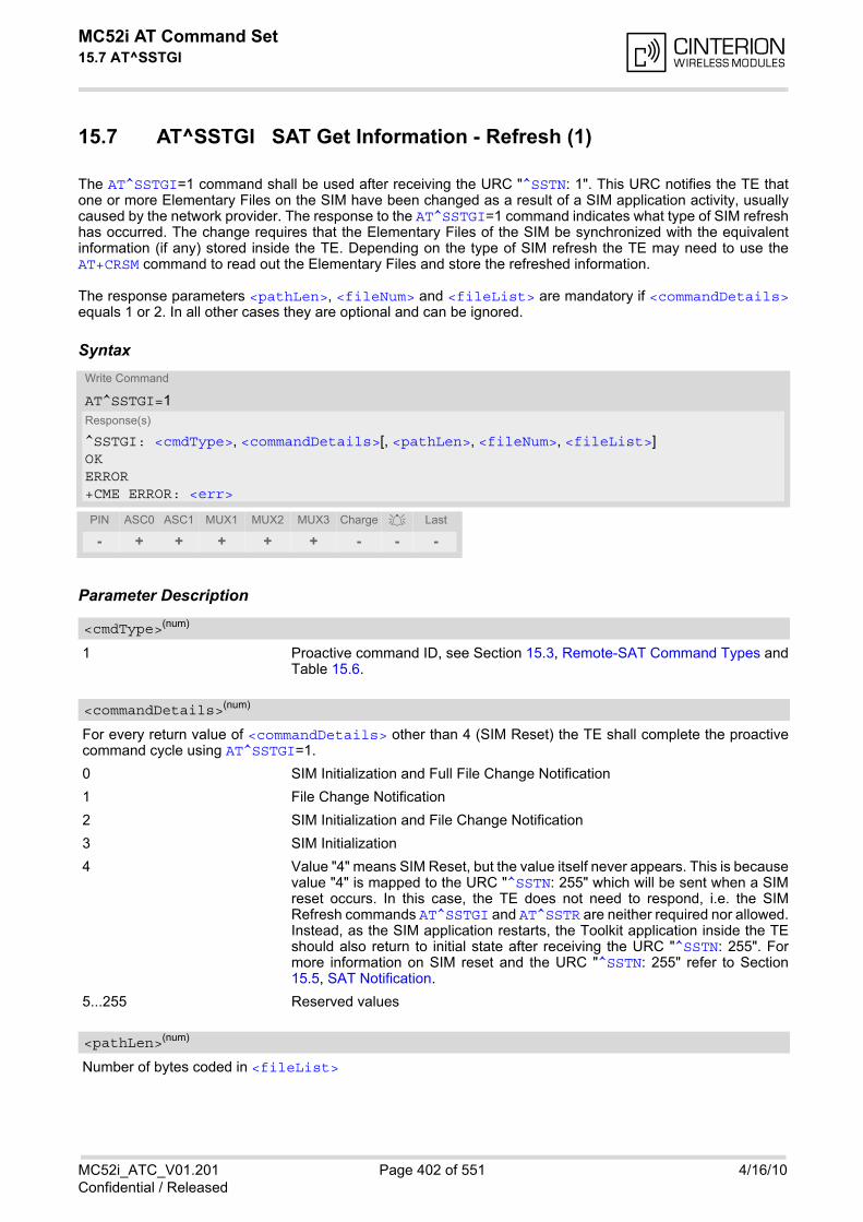
MC52i AT Command Set 15.7 AT^SSTGI
MC52i_ATC_V01.201 Page 402 of 551 4/16/10Confidential / Released
15.7 AT^SSTGI SAT Get Information - Refresh (1)
The AT^SSTGI=1 command shall be used after receiving the URC "^SSTN: 1". This URC notifies the TE thatone or more Elementary Files on the SIM have been changed as a result of a SIM application activity, usuallycaused by the network provider. The response to the AT^SSTGI=1 command indicates what type of SIM refreshhas occurred. The change requires that the Elementary Files of the SIM be synchronized with the equivalentinformation (if any) stored inside the TE. Depending on the type of SIM refresh the TE may need to use theAT+CRSM command to read out the Elementary Files and store the refreshed information.
The response parameters <pathLen>, <fileNum> and <fileList> are mandatory if <commandDetails>equals 1 or 2. In all other cases they are optional and can be ignored.
Syntax
Parameter Description
1 Proactive command ID, see Section 15.3, Remote-SAT Command Types andTable 15.6.
For every return value of <commandDetails> other than 4 (SIM Reset) the TE shall complete the proactivecommand cycle using AT^SSTGI=1.
0 SIM Initialization and Full File Change Notification
1 File Change Notification
2 SIM Initialization and File Change Notification
3 SIM Initialization
4 Value "4" means SIM Reset, but the value itself never appears. This is becausevalue "4" is mapped to the URC "^SSTN: 255" which will be sent when a SIMreset occurs. In this case, the TE does not need to respond, i.e. the SIMRefresh commands AT^SSTGI and AT^SSTR are neither required nor allowed.Instead, as the SIM application restarts, the Toolkit application inside the TEshould also return to initial state after receiving the URC "^SSTN: 255". Formore information on SIM reset and the URC "^SSTN: 255" refer to Section15.5, SAT Notification.
5...255 Reserved values
Number of bytes coded in <fileList>
Write Command
AT^SSTGI=1Response(s)
^SSTGI: <cmdType>, <commandDetails>[, <pathLen>, <fileNum>, <fileList>]OKERROR+CME ERROR: <err>
PIN ASC0 ASC1 MUX1 MUX2 MUX3 Charge Last
- + + + + + - - -
<cmdType>(num)
<commandDetails>(num)
<pathLen>(num)
MC52i AT Command Set 15.7 AT^SSTGI
MC52i_ATC_V01.201 Page 403 of 551 4/16/10Confidential / Released
Number of updated Elementary Files (EF) with path given in <fileList>
String containing Elementary File paths. Each path contains at least two file entries; each file entry (MF, EF orDF) consists of two bytes, e.g. '3F002FE2' or '3F007F206FAD'. Every path in the file description begins with theMaster File (MF). There can be any number of Dedicated File (DF) entries between Master File and ElementaryFile.
<fileNum>(num)
<fileList>(num)
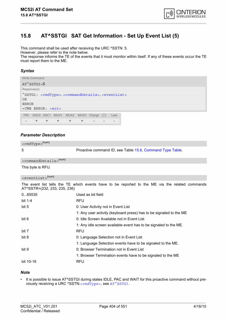
MC52i AT Command Set 15.8 AT^SSTGI
MC52i_ATC_V01.201 Page 404 of 551 4/16/10Confidential / Released
15.8 AT^SSTGI SAT Get Information - Set Up Event List (5)
This command shall be used after receiving the URC ^SSTN: 5.However, please refer to the note below.The response informs the TE of the events that it must monitor within itself. If any of these events occur the TEmust report them to the ME.
Syntax
Parameter Description
5 Proactive command ID, see Table 15.6, Command Type Table.
This byte is RFU.
The event list tells the TE which events have to be reported to the ME via the related commandsAT^SSTR=(232, 233, 235, 236)
0...65535 Used as bit field
bit 1-4 RFU
bit 5 0: User Activity not in Event List
1: Any user activity (keyboard press) has to be signaled to the ME
bit 6 0: Idle Screen Available not in Event List
1: Any idle screen available event has to be signaled to the ME.
bit 7 RFU
bit 8 0: Language Selection not in Event List
1: Language Selection events have to be signaled to the ME.
bit 9 0: Browser Termination not in Event List
1: Browser Termination events have to be signaled to the ME
bit 10-16 RFU
Note• It is possible to issue AT^SSTGI during states IDLE, PAC and WAIT for this proactive command without pre-
viously receiving a URC ^SSTN:<cmdType>, see AT^SSTGI.
Write Command
AT^SSTGI=5Response(s)
^SSTGI: <cmdType>, <commandDetails>, <eventList>OKERROR+CME ERROR: <err>
PIN ASC0 ASC1 MUX1 MUX2 MUX3 Charge Last
- + + + + + - - -
<cmdType>(num)
<commandDetails>(num)
<eventList>(num)
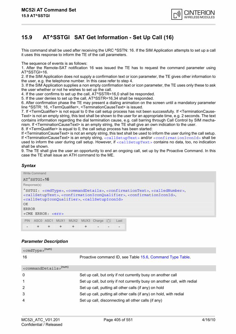
MC52i AT Command Set 15.9 AT^SSTGI
MC52i_ATC_V01.201 Page 405 of 551 4/16/10Confidential / Released
15.9 AT^SSTGI SAT Get Information - Set Up Call (16)
This command shall be used after receiving the URC ^SSTN: 16. If the SIM Application attempts to set up a callit uses this response to inform the TE of the call parameters.
The sequence of events is as follows:1. After the Remote-SAT notification 16 was issued the TE has to request the command parameter usingAT^SSTGI=16.2. If the SIM Application does not supply a confirmation text or icon parameter, the TE gives other information tothe user, e.g. the telephone number. In this case refer to step 4.3. If the SIM Application supplies a non empty confirmation text or icon parameter, the TE uses only these to askthe user whether or not he wishes to set up the call.4. If the user confirms to set up the call, AT^SSTR=16,0 shall be responded.5. If the user denies to set up the call, AT^SSTR=16,34 shall be responded.6. After confirmation phase the TE may present a dialing animation on the screen until a mandatory parameterline ^SSTR: 16, <TermQualifier>, <TerminationCauseText> is issued.7. If <TermQualifier> is not equal to 0 the call setup process has not been successfully. If <TerminationCause-Text> is not an empty string, this text shall be shown to the user for an appropriate time, e.g. 2 seconds. The textcontains information regarding the dial termination cause, e.g. call barring through Call Control by SIM mecha-nism. If <TerminationCauseText> is an empty string, the TE shall give an own indication to the user.8. If <TermQualifier> is equal to 0, the call setup process has been started:If <TerminationCauseText> is not an empty string, this text shall be used to inform the user during the call setup.If <TerminationCauseText> is an empty string, <callSetupText> and/or <confirmationIconId> shall beused to inform the user during call setup. However, if <callSetupText> contains no data, too, no indicationshall be shown.9. The TE shall give the user an opportunity to end an ongoing call, set up by the Proactive Command. In thiscase the TE shall issue an ATH command to the ME.
Syntax
Parameter Description
16 Proactive command ID, see Table 15.6, Command Type Table.
0 Set up call, but only if not currently busy on another call
1 Set up call, but only if not currently busy on another call, with redial
2 Set up call, putting all other calls (if any) on hold
3 Set up call, putting all other calls (if any) on hold, with redial
4 Set up call, disconnecting all other calls (if any)
Write Command
AT^SSTGI=16Response(s)
^SSTGI: <cmdType>, <commandDetails>, <confirmationText>, <calledNumber>, <callSetupText>, <confirmationIconQualifier>, <confirmationIconId>, <callSetupIconQualifier>, <callSetupIconId>OKERROR+CME ERROR: <err>
PIN ASC0 ASC1 MUX1 MUX2 MUX3 Charge Last
- + + + + + - - -
<cmdType>(num)
<commandDetails>(num)

MC52i AT Command Set 15.9 AT^SSTGI
MC52i_ATC_V01.201 Page 406 of 551 4/16/10Confidential / Released
5 Set up call, disconnecting all other calls (if any), with redial
6...255 Reserved Values
String for user confirmation stage
String containing called number
String for call set up stage
0...255 Used as bit field
bit 1 0: Icon is self explanatory and replaces text
1: Icon is not self-explanatory and shall be displayed with the text Determinedvalue only if associated icon ID is not 0 (an icon exists).
bit 2-8 RFU
0...255
0 No Icon
0...255 Used as bit field
bit 1 0: Icon is self explanatory and replaces text
1: Icon is not self-explanatory and shall be displayed with the text Determinedvalue only if associated icon ID is not 0 (an icon exists).
bit 2-8 RFU
0...255
0 No Icon
Note• If the Fixed Dialling Number service is enabled, the number included in the SET UP CALL proactive command
shall not be checked against those of the FDN list.
<confirmationText>(str)
<calledNumber>(num)
<callSetupText>(str)
<confirmationIconQualifier>(num)
<confirmationIconId>(num)
<callSetupIconQualifier>(num)
<callSetupIconId>(num)
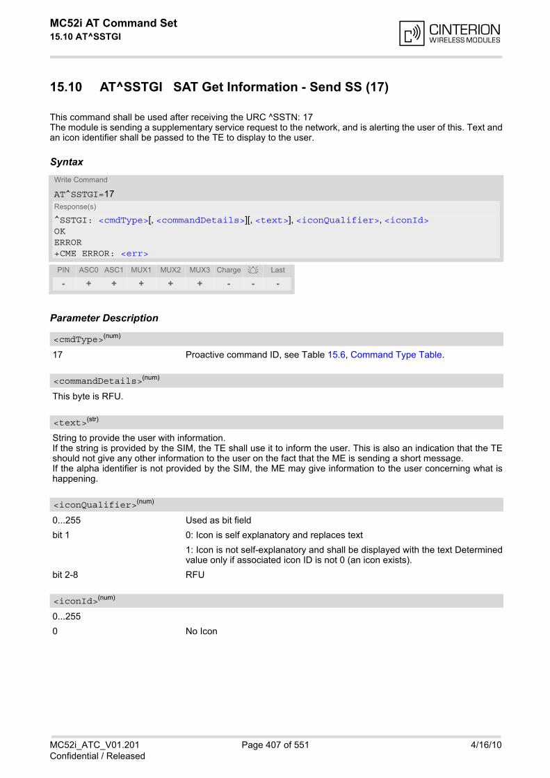
MC52i AT Command Set 15.10 AT^SSTGI
MC52i_ATC_V01.201 Page 407 of 551 4/16/10Confidential / Released
15.10 AT^SSTGI SAT Get Information - Send SS (17)
This command shall be used after receiving the URC ^SSTN: 17The module is sending a supplementary service request to the network, and is alerting the user of this. Text andan icon identifier shall be passed to the TE to display to the user.
Syntax
Parameter Description
17 Proactive command ID, see Table 15.6, Command Type Table.
This byte is RFU.
String to provide the user with information.If the string is provided by the SIM, the TE shall use it to inform the user. This is also an indication that the TEshould not give any other information to the user on the fact that the ME is sending a short message.If the alpha identifier is not provided by the SIM, the ME may give information to the user concerning what ishappening.
0...255 Used as bit field
bit 1 0: Icon is self explanatory and replaces text
1: Icon is not self-explanatory and shall be displayed with the text Determinedvalue only if associated icon ID is not 0 (an icon exists).
bit 2-8 RFU
0...255
0 No Icon
Write Command
AT^SSTGI=17Response(s)
^SSTGI: <cmdType>[, <commandDetails>][, <text>], <iconQualifier>, <iconId>OKERROR+CME ERROR: <err>
PIN ASC0 ASC1 MUX1 MUX2 MUX3 Charge Last
- + + + + + - - -
<cmdType>(num)
<commandDetails>(num)
<text>(str)
<iconQualifier>(num)
<iconId>(num)
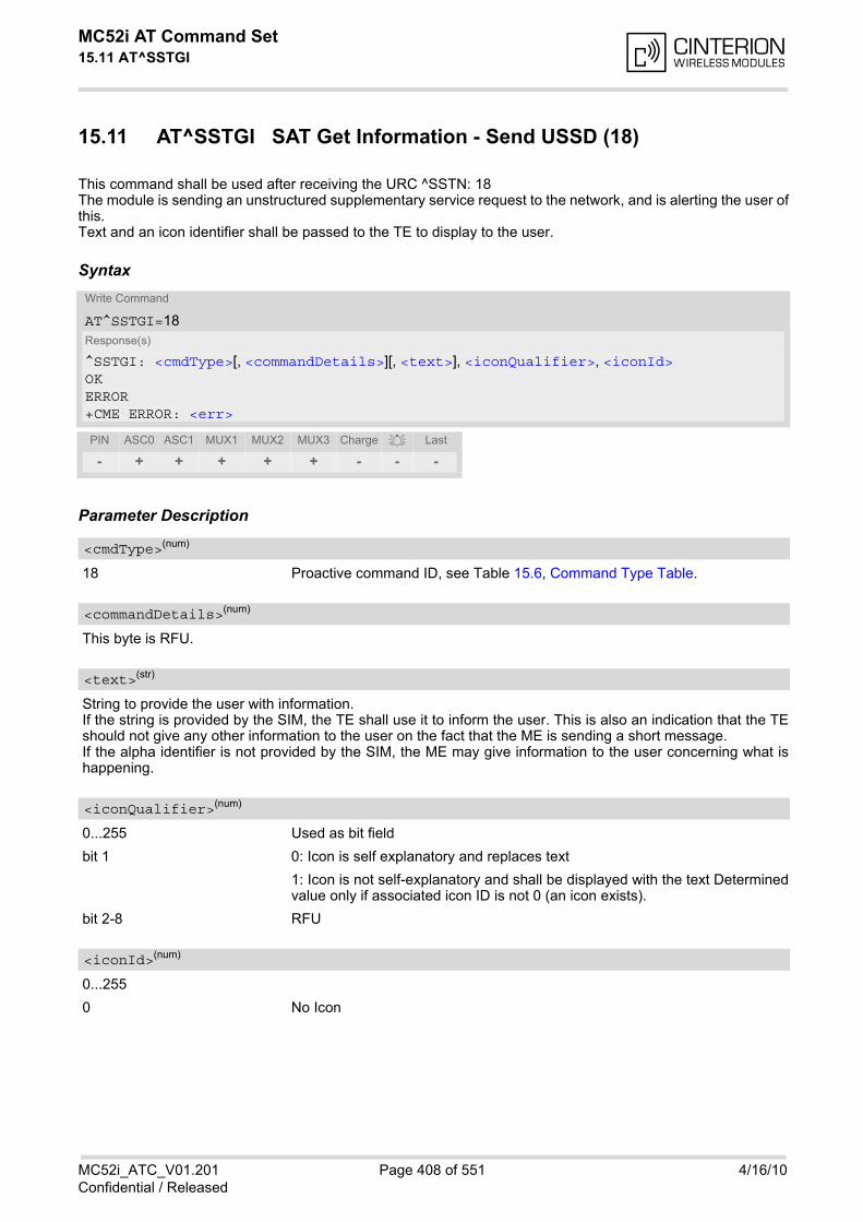
MC52i AT Command Set 15.11 AT^SSTGI
MC52i_ATC_V01.201 Page 408 of 551 4/16/10Confidential / Released
15.11 AT^SSTGI SAT Get Information - Send USSD (18)
This command shall be used after receiving the URC ^SSTN: 18The module is sending an unstructured supplementary service request to the network, and is alerting the user ofthis.Text and an icon identifier shall be passed to the TE to display to the user.
Syntax
Parameter Description
18 Proactive command ID, see Table 15.6, Command Type Table.
This byte is RFU.
String to provide the user with information.If the string is provided by the SIM, the TE shall use it to inform the user. This is also an indication that the TEshould not give any other information to the user on the fact that the ME is sending a short message.If the alpha identifier is not provided by the SIM, the ME may give information to the user concerning what ishappening.
0...255 Used as bit field
bit 1 0: Icon is self explanatory and replaces text
1: Icon is not self-explanatory and shall be displayed with the text Determinedvalue only if associated icon ID is not 0 (an icon exists).
bit 2-8 RFU
0...255
0 No Icon
Write Command
AT^SSTGI=18Response(s)
^SSTGI: <cmdType>[, <commandDetails>][, <text>], <iconQualifier>, <iconId>OKERROR+CME ERROR: <err>
PIN ASC0 ASC1 MUX1 MUX2 MUX3 Charge Last
- + + + + + - - -
<cmdType>(num)
<commandDetails>(num)
<text>(str)
<iconQualifier>(num)
<iconId>(num)
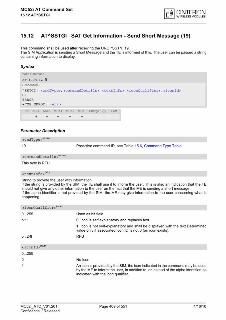
MC52i AT Command Set 15.12 AT^SSTGI
MC52i_ATC_V01.201 Page 409 of 551 4/16/10Confidential / Released
15.12 AT^SSTGI SAT Get Information - Send Short Message (19)
This command shall be used after receiving the URC ^SSTN: 19The SIM Application is sending a Short Message and the TE is informed of this. The user can be passed a stringcontaining information to display.
Syntax
Parameter Description
19 Proactive command ID, see Table 15.6, Command Type Table.
This byte is RFU.
String to provide the user with information.If the string is provided by the SIM, the TE shall use it to inform the user. This is also an indication that the TEshould not give any other information to the user on the fact that the ME is sending a short message.If the alpha identifier is not provided by the SIM, the ME may give information to the user concerning what ishappening.
0...255 Used as bit field
bit 1 0: Icon is self explanatory and replaces text
1: Icon is not self-explanatory and shall be displayed with the text Determinedvalue only if associated icon ID is not 0 (an icon exists).
bit 2-8 RFU
0...255
0 No Icon
1 An icon is provided by the SIM, the icon indicated in the command may be usedby the ME to inform the user, in addition to, or instead of the alpha identifier, asindicated with the icon qualifier.
Write Command
AT^SSTGI=19Response(s)
^SSTGI: <cmdType>, <commandDetails>, <textInfo>, <iconQualifier>, <iconId>OKERROR+CME ERROR: <err>
PIN ASC0 ASC1 MUX1 MUX2 MUX3 Charge Last
- + + + + + - - -
<cmdType>(num)
<commandDetails>(num)
<textInfo>(str)
<iconQualifier>(num)
<iconId>(num)
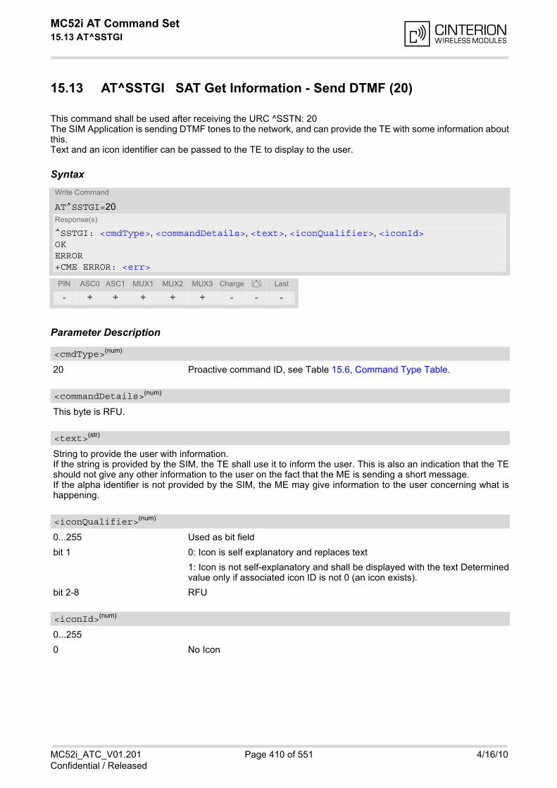
MC52i AT Command Set 15.13 AT^SSTGI
MC52i_ATC_V01.201 Page 410 of 551 4/16/10Confidential / Released
15.13 AT^SSTGI SAT Get Information - Send DTMF (20)
This command shall be used after receiving the URC ^SSTN: 20The SIM Application is sending DTMF tones to the network, and can provide the TE with some information aboutthis.Text and an icon identifier can be passed to the TE to display to the user.
Syntax
Parameter Description
20 Proactive command ID, see Table 15.6, Command Type Table.
This byte is RFU.
String to provide the user with information.If the string is provided by the SIM, the TE shall use it to inform the user. This is also an indication that the TEshould not give any other information to the user on the fact that the ME is sending a short message.If the alpha identifier is not provided by the SIM, the ME may give information to the user concerning what ishappening.
0...255 Used as bit field
bit 1 0: Icon is self explanatory and replaces text
1: Icon is not self-explanatory and shall be displayed with the text Determinedvalue only if associated icon ID is not 0 (an icon exists).
bit 2-8 RFU
0...255
0 No Icon
Write Command
AT^SSTGI=20Response(s)
^SSTGI: <cmdType>, <commandDetails>, <text>, <iconQualifier>, <iconId>OKERROR+CME ERROR: <err>
PIN ASC0 ASC1 MUX1 MUX2 MUX3 Charge Last
- + + + + + - - -
<cmdType>(num)
<commandDetails>(num)
<text>(str)
<iconQualifier>(num)
<iconId>(num)
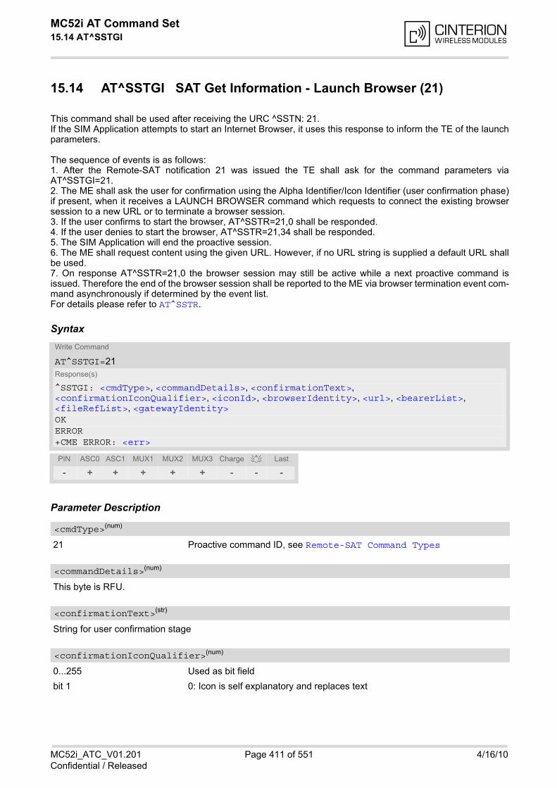
MC52i AT Command Set 15.14 AT^SSTGI
MC52i_ATC_V01.201 Page 411 of 551 4/16/10Confidential / Released
15.14 AT^SSTGI SAT Get Information - Launch Browser (21)
This command shall be used after receiving the URC ^SSTN: 21.If the SIM Application attempts to start an Internet Browser, it uses this response to inform the TE of the launchparameters.
The sequence of events is as follows:1. After the Remote-SAT notification 21 was issued the TE shall ask for the command parameters viaAT^SSTGI=21.2. The ME shall ask the user for confirmation using the Alpha Identifier/Icon Identifier (user confirmation phase)if present, when it receives a LAUNCH BROWSER command which requests to connect the existing browsersession to a new URL or to terminate a browser session.3. If the user confirms to start the browser, AT^SSTR=21,0 shall be responded.4. If the user denies to start the browser, AT^SSTR=21,34 shall be responded.5. The SIM Application will end the proactive session. 6. The ME shall request content using the given URL. However, if no URL string is supplied a default URL shallbe used.7. On response AT^SSTR=21,0 the browser session may still be active while a next proactive command isissued. Therefore the end of the browser session shall be reported to the ME via browser termination event com-mand asynchronously if determined by the event list.For details please refer to AT^SSTR.
Syntax
Parameter Description
21 Proactive command ID, see Remote-SAT Command Types
This byte is RFU.
String for user confirmation stage
0...255 Used as bit field
bit 1 0: Icon is self explanatory and replaces text
Write Command
AT^SSTGI=21Response(s)
^SSTGI: <cmdType>, <commandDetails>, <confirmationText>, <confirmationIconQualifier>, <iconId>, <browserIdentity>, <url>, <bearerList>, <fileRefList>, <gatewayIdentity>OKERROR+CME ERROR: <err>
PIN ASC0 ASC1 MUX1 MUX2 MUX3 Charge Last
- + + + + + - - -
<cmdType>(num)
<commandDetails>(num)
<confirmationText>(str)
<confirmationIconQualifier>(num)
MC52i AT Command Set 15.14 AT^SSTGI
MC52i_ATC_V01.201 Page 412 of 551 4/16/10Confidential / Released
1: Icon is not self-explanatory and shall be displayed with the text Determinedvalue only if associated icon ID is not 0 (an icon exists).
bit 2-8 RFU
0...255
0 No Icon
0...255 Browser to be used
0 Default Browser shall be used.
1...255 RFU
String containing URL to be used by the TE to request content. The way the ME requests content using the URLis out of the scope of the present document. This is specified in RFC 1738 Annex K for example.
“00“ SMS
“01“ CSD
“02“ USSD
“03“ GPRS
04...FF RFU
String containing full path to the provisioning file. The first byte contains the number of files. Every comma sep-arated path is the concatenation of file identifiers starting from the Master File (e.g. 3F007F206FXY). The filecontains a single unambiguous set of parameters required to make the connection. The content of the file isexpected to be consistent with the format defined for provisioning information for the requested type of browser.
String containing the Gateway/Proxy Identity which gives to the mobile the name/identity of the Gateway/Proxyto be used for connecting to the URL. This Gateway/Proxy identity is required when the bearer data object ispresent.
<iconId>(num)
<browserIdentity>(num)
<url>(str)
<bearerList>(str)
<fileRefList>(str)
<gatewayIdentity>(str)
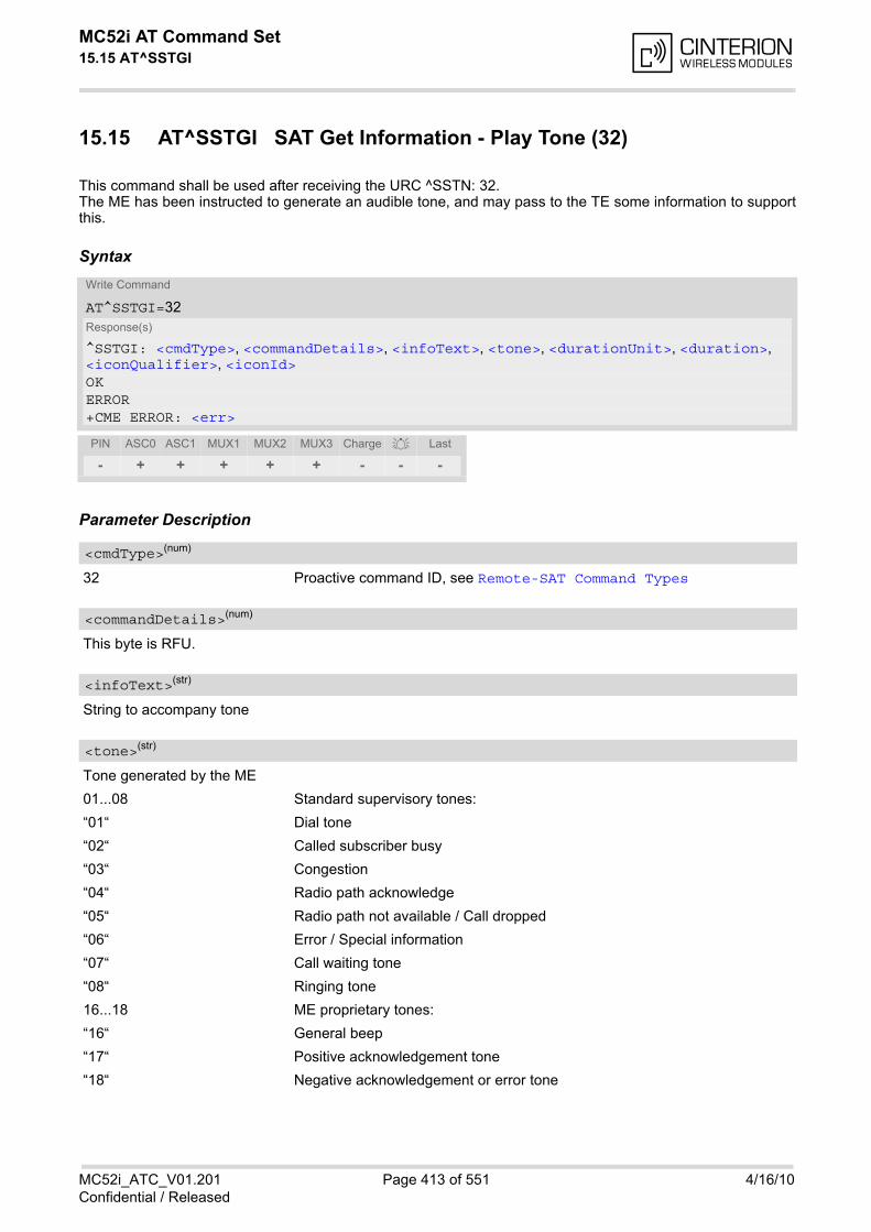
MC52i AT Command Set 15.15 AT^SSTGI
MC52i_ATC_V01.201 Page 413 of 551 4/16/10Confidential / Released
15.15 AT^SSTGI SAT Get Information - Play Tone (32)
This command shall be used after receiving the URC ^SSTN: 32.The ME has been instructed to generate an audible tone, and may pass to the TE some information to supportthis.
Syntax
Parameter Description
32 Proactive command ID, see Remote-SAT Command Types
This byte is RFU.
String to accompany tone
Tone generated by the ME
01...08 Standard supervisory tones:
“01“ Dial tone
“02“ Called subscriber busy
“03“ Congestion
“04“ Radio path acknowledge
“05“ Radio path not available / Call dropped
“06“ Error / Special information
“07“ Call waiting tone
“08“ Ringing tone
16...18 ME proprietary tones:
“16“ General beep
“17“ Positive acknowledgement tone
“18“ Negative acknowledgement or error tone
Write Command
AT^SSTGI=32Response(s)
^SSTGI: <cmdType>, <commandDetails>, <infoText>, <tone>, <durationUnit>, <duration>, <iconQualifier>, <iconId>OKERROR+CME ERROR: <err>
PIN ASC0 ASC1 MUX1 MUX2 MUX3 Charge Last
- + + + + + - - -
<cmdType>(num)
<commandDetails>(num)
<infoText>(str)
<tone>(str)

MC52i AT Command Set 15.15 AT^SSTGI
MC52i_ATC_V01.201 Page 414 of 551 4/16/10Confidential / Released
0 Minutes
1 Seconds
2 Tenth of Seconds
1...255 Duration of tone, expressed in units
0...255 Used as bit field
bit 1 0: Icon is self explanatory and replaces text
1: Icon is not self-explanatory and shall be displayed with the text Determinedvalue only if associated icon ID is not 0 (an icon exists).
bit 2-8 RFU
0...255
0 No Icon
<durationUnit>(num)
<duration>(num)
<iconQualifier>(num)
<iconId>(num)
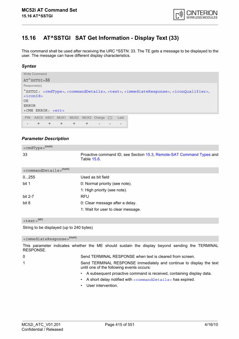
MC52i AT Command Set 15.16 AT^SSTGI
MC52i_ATC_V01.201 Page 415 of 551 4/16/10Confidential / Released
15.16 AT^SSTGI SAT Get Information - Display Text (33)
This command shall be used after receiving the URC ^SSTN: 33. The TE gets a message to be displayed to theuser. The message can have different display characteristics.
Syntax
Parameter Description
33 Proactive command ID, see Section 15.3, Remote-SAT Command Types andTable 15.6.
0...255 Used as bit field
bit 1 0: Normal priority (see note).
1: High priority (see note).
bit 2-7 RFU
bit 8 0: Clear message after a delay.
1: Wait for user to clear message.
String to be displayed (up to 240 bytes)
This parameter indicates whether the ME should sustain the display beyond sending the TERMINALRESPONSE.
0 Send TERMINAL RESPONSE when text is cleared from screen.
1 Send TERMINAL RESPONSE immediately and continue to display the textuntil one of the following events occurs:
• A subsequent proactive command is received, containing display data.
• A short delay notified with <commandDetails> has expired.
• User intervention.
Write Command
AT^SSTGI=33Response(s)
^SSTGI: <cmdType>, <commandDetails>, <text>, <immediateResponse>, <iconQualifier>, <iconId>OKERROR+CME ERROR: <err>
PIN ASC0 ASC1 MUX1 MUX2 MUX3 Charge Last
- + + + + + - - -
<cmdType>(num)
<commandDetails>(num)
<text>(str)
<immediateResponse>(num)
MC52i AT Command Set 15.16 AT^SSTGI
MC52i_ATC_V01.201 Page 416 of 551 4/16/10Confidential / Released
• A higher priority event occurs, e.g. a mobile terminated call.
No further TERMINAL RESPONSE shall be sent when the ME removes thetext from the display, regardless of the cause.If the <immediateResponse> parameter equals "1" the subsequent "^SSTN:254" URC should not be used to clear the text from the screen - in this case thetext should remain on the screen until one of the above events occurs.
0...255 Used as bit field
bit 1 0: Icon is self explanatory and replaces text.
1: Icon is not self-explanatory and shall be displayed with the text Determinedvalue only if associated icon ID is not 0 (an icon exists).
bit 2-8 RFU
0...255
0 No Icon
Notes• The MMI shall reject normal priority text commands if the screen is currently used for more than its normal
standby display, e.g. if the MMI is in sub-menu. If the command is rejected, the MMI sends the TERMINALRESPONSE message to the SIM (ME currently unable to process command - screen busy).
• High priority text shall be displayed on the screen immediately, except if a priority conflict of the alerting eventsoccurs, e.g. incoming call or a URC if the battery needs to be charged, see GSM 11.14, Chapter "ProactiveSIM commands and procedures, Display Text".
<iconQualifier>(num)
<iconId>(num)
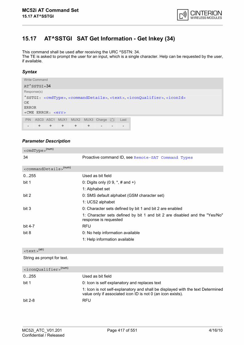
MC52i AT Command Set 15.17 AT^SSTGI
MC52i_ATC_V01.201 Page 417 of 551 4/16/10Confidential / Released
15.17 AT^SSTGI SAT Get Information - Get Inkey (34)
This command shall be used after receiving the URC ^SSTN: 34.The TE is asked to prompt the user for an input, which is a single character. Help can be requested by the user,if available.
Syntax
Parameter Description
34 Proactive command ID, see Remote-SAT Command Types
0...255 Used as bit field
bit 1 0: Digits only (0 9, *, # and +)
1: Alphabet set
bit 2 0: SMS default alphabet (GSM character set)
1: UCS2 alphabet
bit 3 0: Character sets defined by bit 1 and bit 2 are enabled
1: Character sets defined by bit 1 and bit 2 are disabled and the "Yes/No"response is requested
bit 4-7 RFU
bit 8 0: No help information available
1: Help information available
String as prompt for text.
0...255 Used as bit field
bit 1 0: Icon is self explanatory and replaces text
1: Icon is not self-explanatory and shall be displayed with the text Determinedvalue only if associated icon ID is not 0 (an icon exists).
bit 2-8 RFU
Write Command
AT^SSTGI=34Response(s)
^SSTGI: <cmdType>, <commandDetails>, <text>, <iconQualifier>, <iconId>OKERROR+CME ERROR: <err>
PIN ASC0 ASC1 MUX1 MUX2 MUX3 Charge Last
- + + + + + - - -
<cmdType>(num)
<commandDetails>(num)
<text>(str)
<iconQualifier>(num)
MC52i AT Command Set 15.17 AT^SSTGI
MC52i_ATC_V01.201 Page 418 of 551 4/16/10Confidential / Released
0...255
0 No Icon
<iconId>(num)
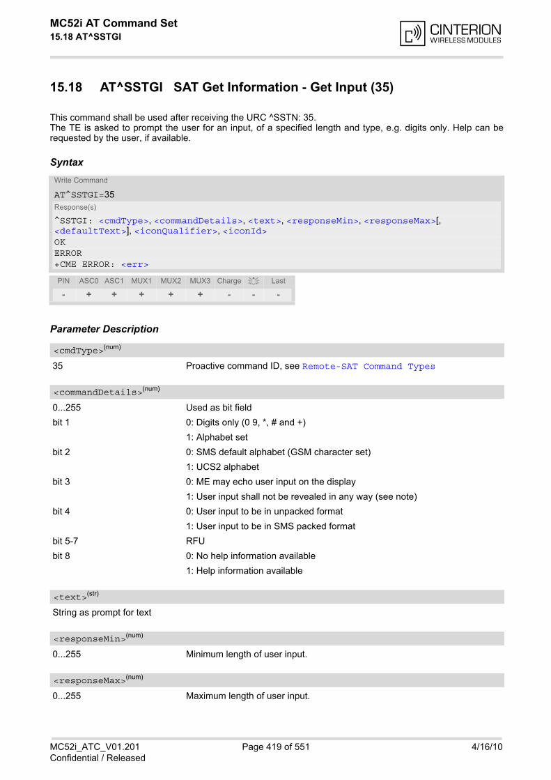
MC52i AT Command Set 15.18 AT^SSTGI
MC52i_ATC_V01.201 Page 419 of 551 4/16/10Confidential / Released
15.18 AT^SSTGI SAT Get Information - Get Input (35)
This command shall be used after receiving the URC ^SSTN: 35.The TE is asked to prompt the user for an input, of a specified length and type, e.g. digits only. Help can berequested by the user, if available.
Syntax
Parameter Description
35 Proactive command ID, see Remote-SAT Command Types
0...255 Used as bit field
bit 1 0: Digits only (0 9, *, # and +)
1: Alphabet set
bit 2 0: SMS default alphabet (GSM character set)
1: UCS2 alphabet
bit 3 0: ME may echo user input on the display
1: User input shall not be revealed in any way (see note)
bit 4 0: User input to be in unpacked format
1: User input to be in SMS packed format
bit 5-7 RFU
bit 8 0: No help information available
1: Help information available
String as prompt for text
0...255 Minimum length of user input.
0...255 Maximum length of user input.
Write Command
AT^SSTGI=35Response(s)
^SSTGI: <cmdType>, <commandDetails>, <text>, <responseMin>, <responseMax>[, <defaultText>], <iconQualifier>, <iconId>OKERROR+CME ERROR: <err>
PIN ASC0 ASC1 MUX1 MUX2 MUX3 Charge Last
- + + + + + - - -
<cmdType>(num)
<commandDetails>(num)
<text>(str)
<responseMin>(num)
<responseMax>(num)

MC52i AT Command Set 15.18 AT^SSTGI
MC52i_ATC_V01.201 Page 420 of 551 4/16/10Confidential / Released
String supplied as default response text
0...255 Used as bit field
bit 1 0: Icon is self explanatory and replaces text
1: Icon is not self-explanatory and shall be displayed with the text Determinedvalue only if associated icon ID is not 0 (an icon exists).
bit 2-8 RFU
0...255
0 No Icon
Note• Hidden entry mode (see GSM 11.14) is only available when using digit input. In hidden entry mode only char-
acters ('0', '9', '*' and '#') are allowed.
<defaultText>(str)
<iconQualifier>(num)
<iconId>(num)
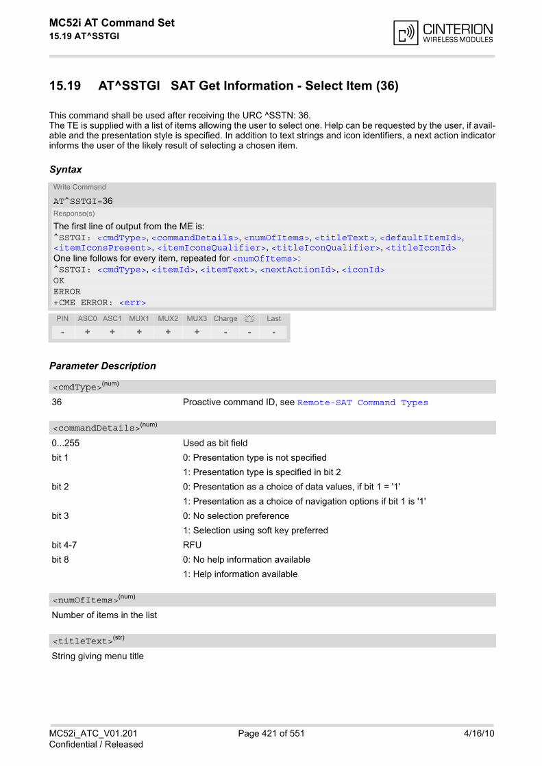
MC52i AT Command Set 15.19 AT^SSTGI
MC52i_ATC_V01.201 Page 421 of 551 4/16/10Confidential / Released
15.19 AT^SSTGI SAT Get Information - Select Item (36)
This command shall be used after receiving the URC ^SSTN: 36.The TE is supplied with a list of items allowing the user to select one. Help can be requested by the user, if avail-able and the presentation style is specified. In addition to text strings and icon identifiers, a next action indicatorinforms the user of the likely result of selecting a chosen item.
Syntax
Parameter Description
36 Proactive command ID, see Remote-SAT Command Types
0...255 Used as bit field
bit 1 0: Presentation type is not specified
1: Presentation type is specified in bit 2
bit 2 0: Presentation as a choice of data values, if bit 1 = '1'
1: Presentation as a choice of navigation options if bit 1 is '1'
bit 3 0: No selection preference
1: Selection using soft key preferred
bit 4-7 RFU
bit 8 0: No help information available
1: Help information available
Number of items in the list
String giving menu title
Write Command
AT^SSTGI=36Response(s)
The first line of output from the ME is:^SSTGI: <cmdType>, <commandDetails>, <numOfItems>, <titleText>, <defaultItemId>, <itemIconsPresent>, <itemIconsQualifier>, <titleIconQualifier>, <titleIconId>One line follows for every item, repeated for <numOfItems>:^SSTGI: <cmdType>, <itemId>, <itemText>, <nextActionId>, <iconId>OKERROR+CME ERROR: <err>
PIN ASC0 ASC1 MUX1 MUX2 MUX3 Charge Last
- + + + + + - - -
<cmdType>(num)
<commandDetails>(num)
<numOfItems>(num)
<titleText>(str)

MC52i AT Command Set 15.19 AT^SSTGI
MC52i_ATC_V01.201 Page 422 of 551 4/16/10Confidential / Released
ID of default itemThe SIM may supply with the list an indication of the default item, e.g. the previously selected item
0 No default item issued by the SIM application
1...255 Id of the default Item
0 No icons
1 Icons present
0...255 Used as bit field
bit 1 0: Icon is self explanatory and replaces text
1: Icon is not self-explanatory and shall be displayed with the text Determinedvalue only if associated icon ID is not 0 (an icon exists).
bit 2-8 RFU
0...255 Used as bit field
bit 1 0: Icon is self explanatory and replaces text
1: Icon is not self-explanatory and shall be displayed with the text Determinedvalue only if associated icon ID is not 0 (an icon exists).
bit 2-8 RFU
0...255
0 No Icon
Item identifier (1 - <numOfItems>)
String giving menu title
The next proactive command type to be issued upon execution of the menu item. See Remote-SAT CommandTypes
0 Next Action information available
0...255
0 No Icon
<defaultItemId>(num)
<itemIconsPresent>(num)
<itemIconsQualifier>(num)
<titleIconQualifier>(num)
<titleIconId>(num)
<itemId>(num)
<itemText>(str)
<nextActionId>(num)
<iconId>(num)
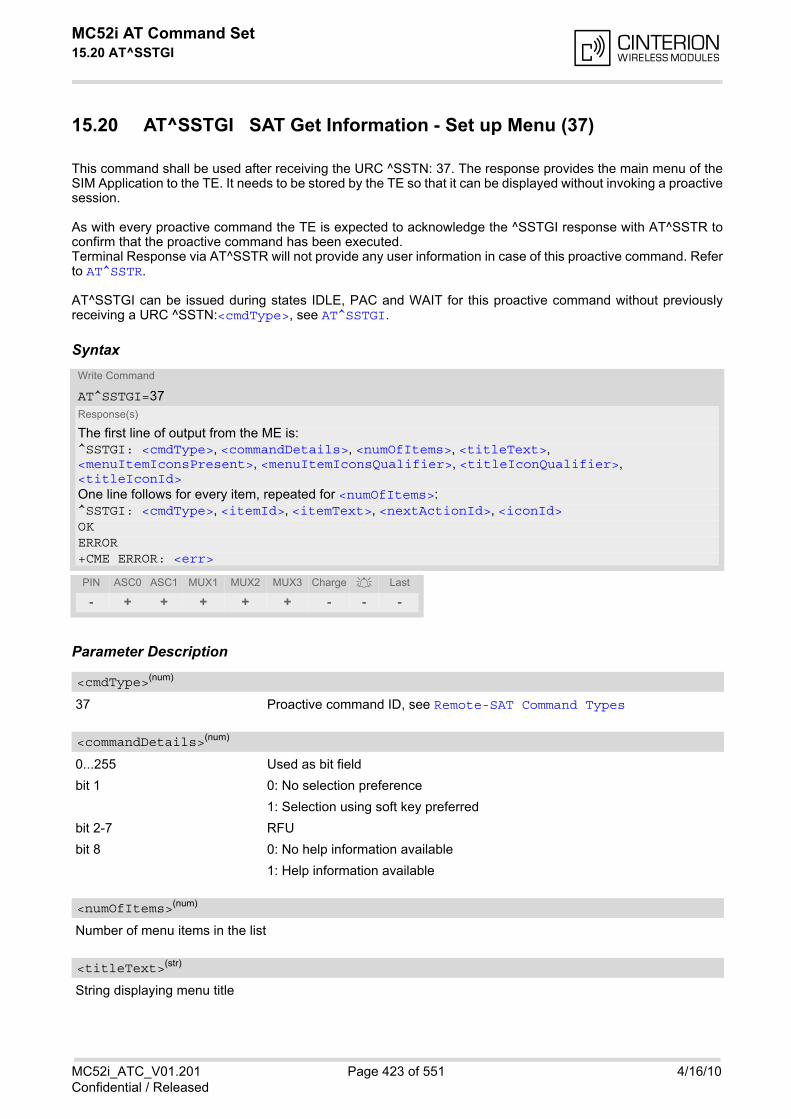
MC52i AT Command Set 15.20 AT^SSTGI
MC52i_ATC_V01.201 Page 423 of 551 4/16/10Confidential / Released
15.20 AT^SSTGI SAT Get Information - Set up Menu (37)
This command shall be used after receiving the URC ^SSTN: 37. The response provides the main menu of theSIM Application to the TE. It needs to be stored by the TE so that it can be displayed without invoking a proactivesession.
As with every proactive command the TE is expected to acknowledge the ^SSTGI response with AT^SSTR toconfirm that the proactive command has been executed.Terminal Response via AT^SSTR will not provide any user information in case of this proactive command. Referto AT^SSTR.
AT^SSTGI can be issued during states IDLE, PAC and WAIT for this proactive command without previouslyreceiving a URC ^SSTN:<cmdType>, see AT^SSTGI.
Syntax
Parameter Description
37 Proactive command ID, see Remote-SAT Command Types
0...255 Used as bit field
bit 1 0: No selection preference
1: Selection using soft key preferred
bit 2-7 RFU
bit 8 0: No help information available
1: Help information available
Number of menu items in the list
String displaying menu title
Write Command
AT^SSTGI=37Response(s)
The first line of output from the ME is:^SSTGI: <cmdType>, <commandDetails>, <numOfItems>, <titleText>, <menuItemIconsPresent>, <menuItemIconsQualifier>, <titleIconQualifier>, <titleIconId>One line follows for every item, repeated for <numOfItems>:^SSTGI: <cmdType>, <itemId>, <itemText>, <nextActionId>, <iconId>OKERROR+CME ERROR: <err>
PIN ASC0 ASC1 MUX1 MUX2 MUX3 Charge Last
- + + + + + - - -
<cmdType>(num)
<commandDetails>(num)
<numOfItems>(num)
<titleText>(str)

MC52i AT Command Set 15.20 AT^SSTGI
MC52i_ATC_V01.201 Page 424 of 551 4/16/10Confidential / Released
0 No icons
1 Icons present
0...255 Used as bit field
bit 1 0: Icon is self explanatory and replaces text
1: Icon is not self-explanatory and shall be displayed with the text Determinedvalue only if associated icon ID is not 0 (an icon exists).
bit 2-8 RFU
0...255 Used as bit field
bit 1 0: Icon is self explanatory and replaces text
1: Icon is not self-explanatory and shall be displayed with the text Determinedvalue only if associated icon ID is not 0 (an icon exists).
bit 2-8 RFU
0...255
0 No Icon
Menu item identifier (1 - <numOfItems>)
Title of menu item
The next proactive command type to be issued upon execution of the menu item. See Remote-SAT CommandTypes
0 No next Action information available
0...255
0 No Icon
<menuItemIconsPresent>(num)
<menuItemIconsQualifier>(num)
<titleIconQualifier>(num)
<titleIconId>(num)
<itemId>(num)
<itemText>(str)
<nextActionId>(num)
<iconId>(num)

MC52i AT Command Set 15.21 AT^SSTGI
MC52i_ATC_V01.201 Page 425 of 551 4/16/10Confidential / Released
15.21 AT^SSTGI SAT Get Information - Set up Idle Mode Text (40)
This command shall be used after receiving the URC ^SSTN: 40.It provides text and optionally an icon to be displayed by the TE when the display is Idle.
Syntax
Parameter Description
40 Proactive command ID, see Remote-SAT Command Types
This byte is RFU.
Text to be displayed when TE in IDLE mode
0...255 Used as bit field
bit 1 0: Icon is self explanatory and replaces text
1: Icon is not self-explanatory and shall be displayed with the text Determinedvalue only if associated icon ID is not 0 (an icon exists).
bit 2-8 RFU
0...255
0 No Icon
Note• AT^SSTGI can be issued during states IDLE, PAC and WAIT for this proactive command without previously
receiving a URC ^SSTN:<cmdType>, see AT^SSTGI.
Write Command
AT^SSTGI=40Response(s)
^SSTGI: <cmdType>, <commandDetails>, <text>, <iconQualifier>, <iconId>OKERROR+CME ERROR: <err>
PIN ASC0 ASC1 MUX1 MUX2 MUX3 Charge Last
- + + + + + - - -
<cmdType>(num)
<commandDetails>(num)
<text>(str)
<iconQualifier>(num)
<iconId>(num)
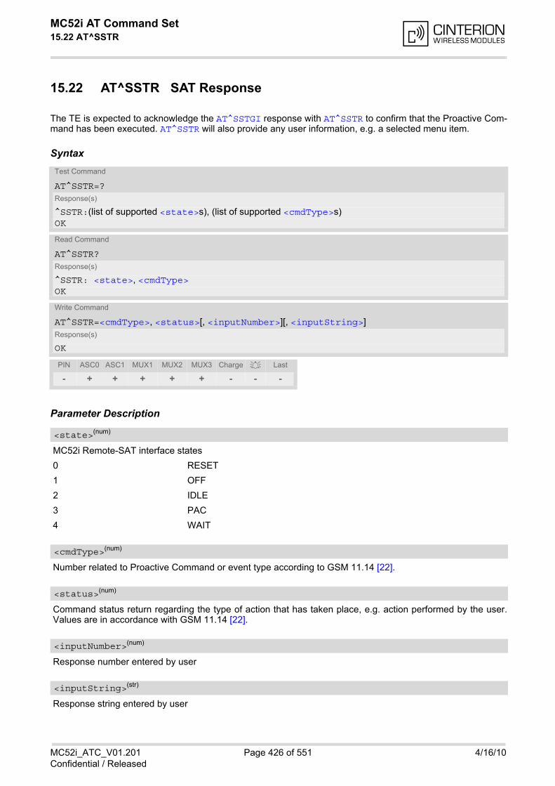
MC52i AT Command Set 15.22 AT^SSTR
MC52i_ATC_V01.201 Page 426 of 551 4/16/10Confidential / Released
15.22 AT^SSTR SAT Response
The TE is expected to acknowledge the AT^SSTGI response with AT^SSTR to confirm that the Proactive Com-mand has been executed. AT^SSTR will also provide any user information, e.g. a selected menu item.
Syntax
Parameter Description
MC52i Remote-SAT interface states
0 RESET
1 OFF
2 IDLE
3 PAC
4 WAIT
Number related to Proactive Command or event type according to GSM 11.14 [22].
Command status return regarding the type of action that has taken place, e.g. action performed by the user.Values are in accordance with GSM 11.14 [22].
Response number entered by user
Response string entered by user
Test Command
AT^SSTR=?Response(s)
^SSTR:(list of supported <state>s), (list of supported <cmdType>s)OK
Read Command
AT^SSTR?Response(s)
^SSTR: <state>, <cmdType>OK
Write Command
AT^SSTR=<cmdType>, <status>[, <inputNumber>][, <inputString>]Response(s)
OK
PIN ASC0 ASC1 MUX1 MUX2 MUX3 Charge Last
- + + + + + - - -
<state>(num)
<cmdType>(num)
<status>(num)
<inputNumber>(num)
<inputString>(str)
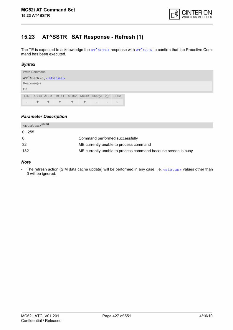
MC52i AT Command Set 15.23 AT^SSTR
MC52i_ATC_V01.201 Page 427 of 551 4/16/10Confidential / Released
15.23 AT^SSTR SAT Response - Refresh (1)
The TE is expected to acknowledge the AT^SSTGI response with AT^SSTR to confirm that the Proactive Com-mand has been executed.
Syntax
Parameter Description
0...255
0 Command performed successfully
32 ME currently unable to process command
132 ME currently unable to process command because screen is busy
Note• The refresh action (SIM data cache update) will be performed in any case, i.e. <status> values other than
0 will be ignored.
Write Command
AT^SSTR=1, <status>Response(s)
OK
PIN ASC0 ASC1 MUX1 MUX2 MUX3 Charge Last
- + + + + + - - -
<status>(num)
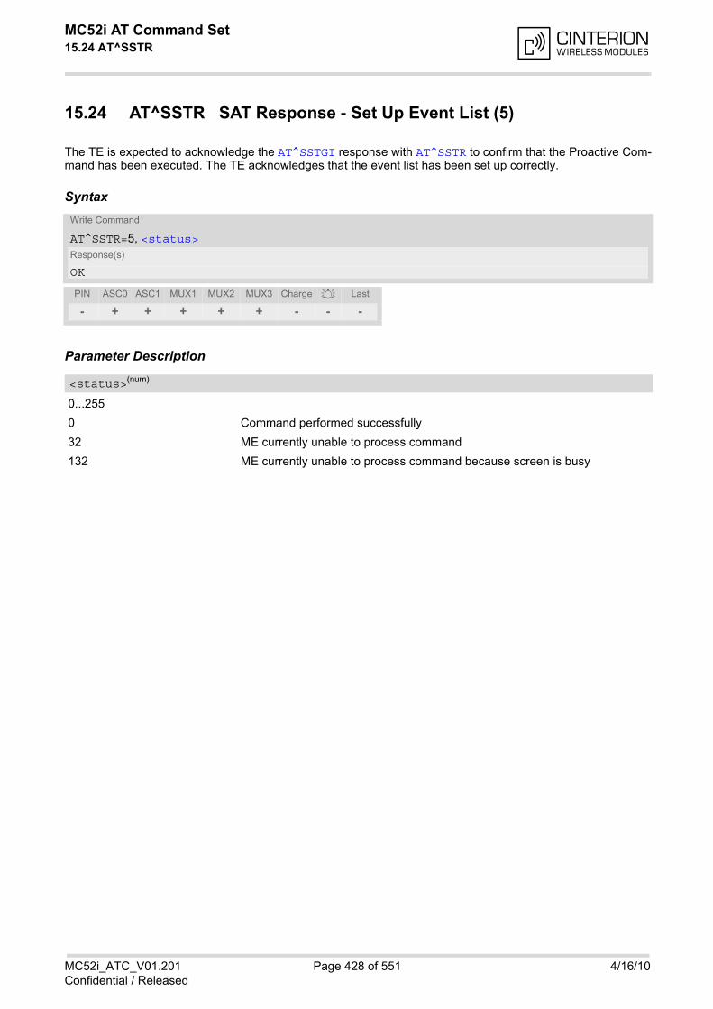
MC52i AT Command Set 15.24 AT^SSTR
MC52i_ATC_V01.201 Page 428 of 551 4/16/10Confidential / Released
15.24 AT^SSTR SAT Response - Set Up Event List (5)
The TE is expected to acknowledge the AT^SSTGI response with AT^SSTR to confirm that the Proactive Com-mand has been executed. The TE acknowledges that the event list has been set up correctly.
Syntax
Parameter Description
0...255
0 Command performed successfully
32 ME currently unable to process command
132 ME currently unable to process command because screen is busy
Write Command
AT^SSTR=5, <status>Response(s)
OK
PIN ASC0 ASC1 MUX1 MUX2 MUX3 Charge Last
- + + + + + - - -
<status>(num)
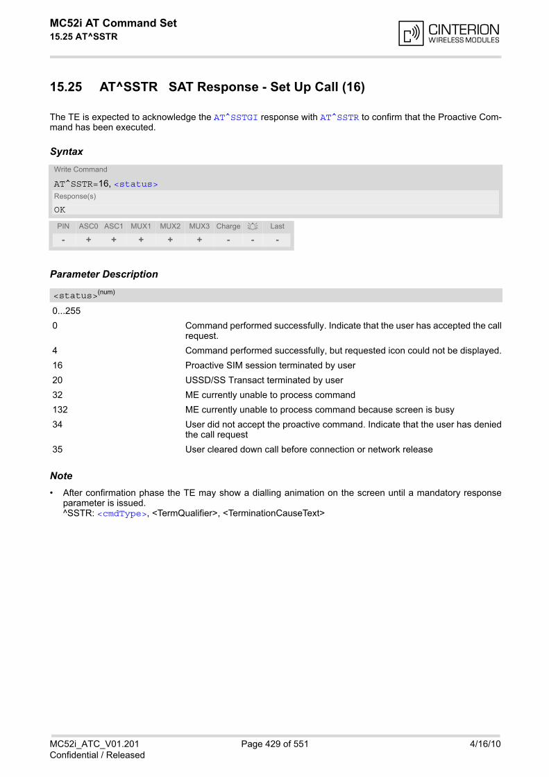
MC52i AT Command Set 15.25 AT^SSTR
MC52i_ATC_V01.201 Page 429 of 551 4/16/10Confidential / Released
15.25 AT^SSTR SAT Response - Set Up Call (16)
The TE is expected to acknowledge the AT^SSTGI response with AT^SSTR to confirm that the Proactive Com-mand has been executed.
Syntax
Parameter Description
0...255
0 Command performed successfully. Indicate that the user has accepted the callrequest.
4 Command performed successfully, but requested icon could not be displayed.
16 Proactive SIM session terminated by user
20 USSD/SS Transact terminated by user
32 ME currently unable to process command
132 ME currently unable to process command because screen is busy
34 User did not accept the proactive command. Indicate that the user has deniedthe call request
35 User cleared down call before connection or network release
Note• After confirmation phase the TE may show a dialling animation on the screen until a mandatory response
parameter is issued.^SSTR: <cmdType>, <TermQualifier>, <TerminationCauseText>
Write Command
AT^SSTR=16, <status>Response(s)
OK
PIN ASC0 ASC1 MUX1 MUX2 MUX3 Charge Last
- + + + + + - - -
<status>(num)
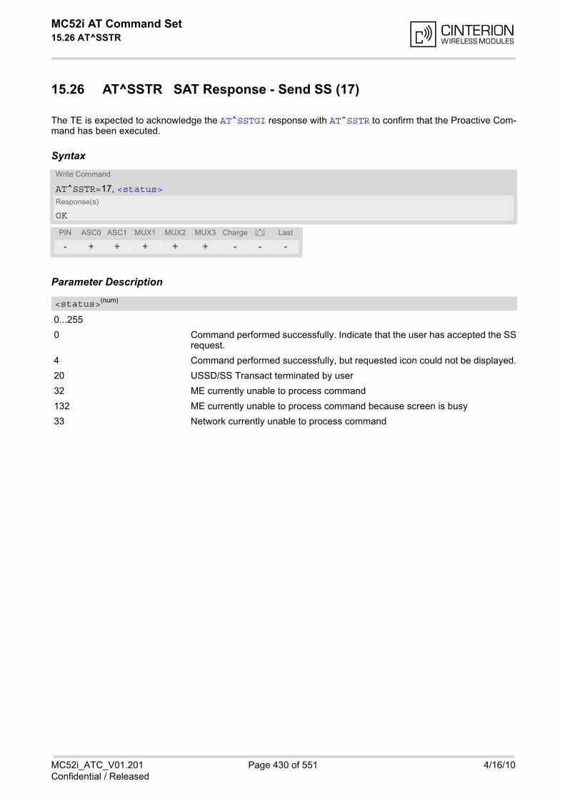
MC52i AT Command Set 15.26 AT^SSTR
MC52i_ATC_V01.201 Page 430 of 551 4/16/10Confidential / Released
15.26 AT^SSTR SAT Response - Send SS (17)
The TE is expected to acknowledge the AT^SSTGI response with AT^SSTR to confirm that the Proactive Com-mand has been executed.
Syntax
Parameter Description
0...255
0 Command performed successfully. Indicate that the user has accepted the SSrequest.
4 Command performed successfully, but requested icon could not be displayed.
20 USSD/SS Transact terminated by user
32 ME currently unable to process command
132 ME currently unable to process command because screen is busy
33 Network currently unable to process command
Write Command
AT^SSTR=17, <status>Response(s)
OK
PIN ASC0 ASC1 MUX1 MUX2 MUX3 Charge Last
- + + + + + - - -
<status>(num)

MC52i AT Command Set 15.27 AT^SSTR
MC52i_ATC_V01.201 Page 431 of 551 4/16/10Confidential / Released
15.27 AT^SSTR SAT Response - Send USSD (18)
The TE is expected to acknowledge the AT^SSTGI response with AT^SSTR to confirm that the Proactive Com-mand has been executed.
Syntax
Parameter Description
0...255
0 Command performed successfully. Indicate that the user has accepted theUSSD request.
4 Command performed successfully, but requested icon could not be displayed.
20 USSD/SS Transact terminated by user
32 ME currently unable to process command
132 ME currently unable to process command because screen is busy
33 Network currently unable to process command
Write Command
AT^SSTR=18, <status>Response(s)
OK
PIN ASC0 ASC1 MUX1 MUX2 MUX3 Charge Last
- + + + + + - - -
<status>(num)
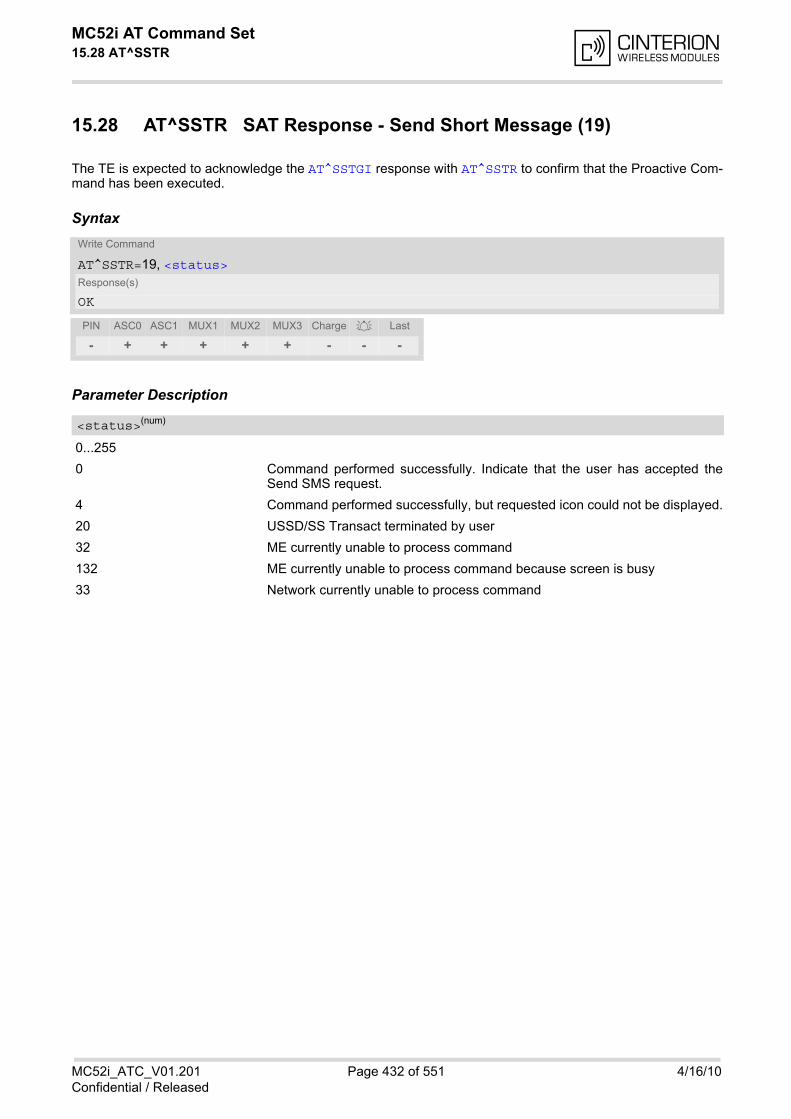
MC52i AT Command Set 15.28 AT^SSTR
MC52i_ATC_V01.201 Page 432 of 551 4/16/10Confidential / Released
15.28 AT^SSTR SAT Response - Send Short Message (19)
The TE is expected to acknowledge the AT^SSTGI response with AT^SSTR to confirm that the Proactive Com-mand has been executed.
Syntax
Parameter Description
0...255
0 Command performed successfully. Indicate that the user has accepted theSend SMS request.
4 Command performed successfully, but requested icon could not be displayed.
20 USSD/SS Transact terminated by user
32 ME currently unable to process command
132 ME currently unable to process command because screen is busy
33 Network currently unable to process command
Write Command
AT^SSTR=19, <status>Response(s)
OK
PIN ASC0 ASC1 MUX1 MUX2 MUX3 Charge Last
- + + + + + - - -
<status>(num)
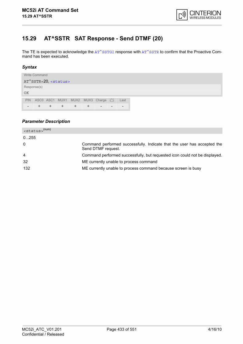
MC52i AT Command Set 15.29 AT^SSTR
MC52i_ATC_V01.201 Page 433 of 551 4/16/10Confidential / Released
15.29 AT^SSTR SAT Response - Send DTMF (20)
The TE is expected to acknowledge the AT^SSTGI response with AT^SSTR to confirm that the Proactive Com-mand has been executed.
Syntax
Parameter Description
0...255
0 Command performed successfully. Indicate that the user has accepted theSend DTMF request.
4 Command performed successfully, but requested icon could not be displayed.
32 ME currently unable to process command
132 ME currently unable to process command because screen is busy
Write Command
AT^SSTR=20, <status>Response(s)
OK
PIN ASC0 ASC1 MUX1 MUX2 MUX3 Charge Last
- + + + + + - - -
<status>(num)
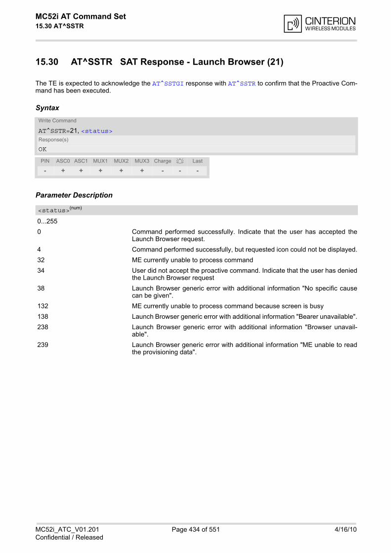
MC52i AT Command Set 15.30 AT^SSTR
MC52i_ATC_V01.201 Page 434 of 551 4/16/10Confidential / Released
15.30 AT^SSTR SAT Response - Launch Browser (21)
The TE is expected to acknowledge the AT^SSTGI response with AT^SSTR to confirm that the Proactive Com-mand has been executed.
Syntax
Parameter Description
0...255
0 Command performed successfully. Indicate that the user has accepted theLaunch Browser request.
4 Command performed successfully, but requested icon could not be displayed.
32 ME currently unable to process command
34 User did not accept the proactive command. Indicate that the user has deniedthe Launch Browser request
38 Launch Browser generic error with additional information "No specific causecan be given".
132 ME currently unable to process command because screen is busy
138 Launch Browser generic error with additional information "Bearer unavailable".
238 Launch Browser generic error with additional information "Browser unavail-able".
239 Launch Browser generic error with additional information "ME unable to readthe provisioning data".
Write Command
AT^SSTR=21, <status>Response(s)
OK
PIN ASC0 ASC1 MUX1 MUX2 MUX3 Charge Last
- + + + + + - - -
<status>(num)
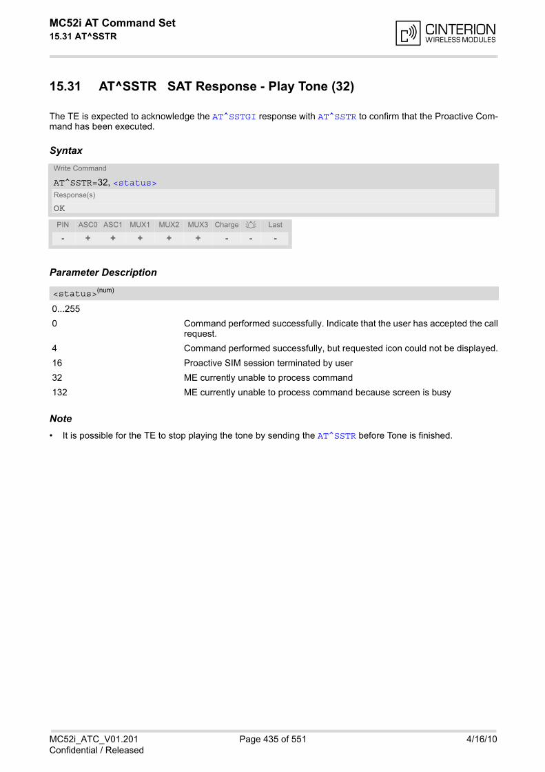
MC52i AT Command Set 15.31 AT^SSTR
MC52i_ATC_V01.201 Page 435 of 551 4/16/10Confidential / Released
15.31 AT^SSTR SAT Response - Play Tone (32)
The TE is expected to acknowledge the AT^SSTGI response with AT^SSTR to confirm that the Proactive Com-mand has been executed.
Syntax
Parameter Description
0...255
0 Command performed successfully. Indicate that the user has accepted the callrequest.
4 Command performed successfully, but requested icon could not be displayed.
16 Proactive SIM session terminated by user
32 ME currently unable to process command
132 ME currently unable to process command because screen is busy
Note• It is possible for the TE to stop playing the tone by sending the AT^SSTR before Tone is finished.
Write Command
AT^SSTR=32, <status>Response(s)
OK
PIN ASC0 ASC1 MUX1 MUX2 MUX3 Charge Last
- + + + + + - - -
<status>(num)
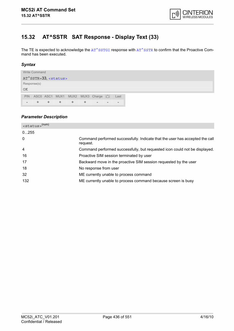
MC52i AT Command Set 15.32 AT^SSTR
MC52i_ATC_V01.201 Page 436 of 551 4/16/10Confidential / Released
15.32 AT^SSTR SAT Response - Display Text (33)
The TE is expected to acknowledge the AT^SSTGI response with AT^SSTR to confirm that the Proactive Com-mand has been executed.
Syntax
Parameter Description
0...255
0 Command performed successfully. Indicate that the user has accepted the callrequest.
4 Command performed successfully, but requested icon could not be displayed.
16 Proactive SIM session terminated by user
17 Backward move in the proactive SIM session requested by the user
18 No response from user
32 ME currently unable to process command
132 ME currently unable to process command because screen is busy
Write Command
AT^SSTR=33, <status>Response(s)
OK
PIN ASC0 ASC1 MUX1 MUX2 MUX3 Charge Last
- + + + + + - - -
<status>(num)
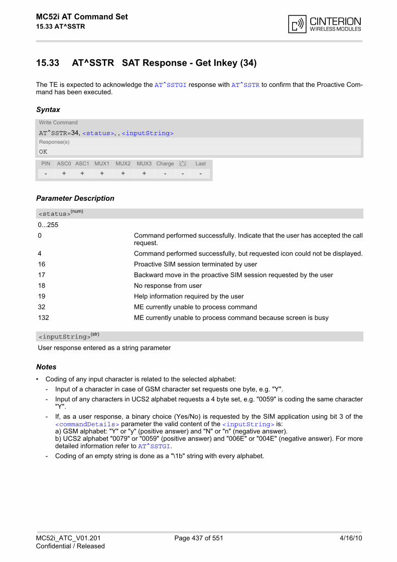
MC52i AT Command Set 15.33 AT^SSTR
MC52i_ATC_V01.201 Page 437 of 551 4/16/10Confidential / Released
15.33 AT^SSTR SAT Response - Get Inkey (34)
The TE is expected to acknowledge the AT^SSTGI response with AT^SSTR to confirm that the Proactive Com-mand has been executed.
Syntax
Parameter Description
0...255
0 Command performed successfully. Indicate that the user has accepted the callrequest.
4 Command performed successfully, but requested icon could not be displayed.
16 Proactive SIM session terminated by user
17 Backward move in the proactive SIM session requested by the user
18 No response from user
19 Help information required by the user
32 ME currently unable to process command
132 ME currently unable to process command because screen is busy
User response entered as a string parameter
Notes• Coding of any input character is related to the selected alphabet:
- Input of a character in case of GSM character set requests one byte, e.g. "Y".
- Input of any characters in UCS2 alphabet requests a 4 byte set, e.g. "0059" is coding the same character"Y".
- If, as a user response, a binary choice (Yes/No) is requested by the SIM application using bit 3 of the<commandDetails> parameter the valid content of the <inputString> is:a) GSM alphabet: "Y" or "y" (positive answer) and "N" or "n" (negative answer).b) UCS2 alphabet "0079" or "0059" (positive answer) and "006E" or "004E" (negative answer). For moredetailed information refer to AT^SSTGI.
- Coding of an empty string is done as a "\1b" string with every alphabet.
Write Command
AT^SSTR=34, <status>, , <inputString>Response(s)
OK
PIN ASC0 ASC1 MUX1 MUX2 MUX3 Charge Last
- + + + + + - - -
<status>(num)
<inputString>(str)
MC52i AT Command Set 15.33 AT^SSTR
MC52i_ATC_V01.201 Page 438 of 551 4/16/10Confidential / Released
• The <Alphabet> parameter of AT^SSTA determines the alphabet used on the AT command interface, whilethe value reported by the <commandDetails> bit 2 of the AT^SSTGI=34 command determines the set ofcharacters allowed. If these alphabet settings are different, the following applies:Example: If UCS2 alphabet is selected with AT^SSTA and the <commandDetails> bit 2 of theAT^SSTGI=34 command is reported as "SMS default alphabet (GSM character set)" any input has to be donein UCS2 alphabet. However, take care to enter only UCS2 characters for which equivalent characters aredefined in the SMS (GSM) default alphabet. In this case, the ME will correctly translate the given UCS2 datainto a TERMINAL RESPONSE coded in SMS (GSM) default alphabet. See also Section 1.6.2, UCS2 andGSM character coding and conversion.

MC52i AT Command Set 15.34 AT^SSTR
MC52i_ATC_V01.201 Page 439 of 551 4/16/10Confidential / Released
15.34 AT^SSTR SAT Response - Get Input (35)
The TE is expected to acknowledge the AT^SSTGI response with AT^SSTR to confirm that the Proactive Com-mand has been executed.
Syntax
Parameter Description
0...255
0 Command performed successfully. Indicate that the user has accepted the callrequest.
4 Command performed successfully, but requested icon could not be displayed.
16 Proactive SIM session terminated by user
17 Backward move in the proactive SIM session requested by the user
18 No response from user
19 Help information required by the user
32 ME currently unable to process command
132 ME currently unable to process command because screen is busy
User response entered as a string, length depends on the <responseMin> and <responseMax> valuesreturned by the related AT^SSTGI=35 command.
Notes• Coding of any input character is related to the selected alphabet:
• Input of a character in case of GSM character set requests one byte, e.g. "Y".• Input of any characters in UCS2 alphabet requests a 4 byte set, e.g. "0059" is coding the same character "Y".• Coding of an empty string is done as a "\1b" string with every alphabet.
• The <Alphabet> parameter of AT^SSTA determines the alphabet used on the AT command interface, whilethe value reported by the <commandDetails> bit 2 of the AT^SSTGI=35 command determines the set ofcharacters allowed. If these alphabet settings are different, the following applies:Example: If UCS2 alphabet is selected with AT^SSTA and the <commandDetails> bit 2 of theAT^SSTGI=35 command is reported as "SMS default alphabet (GSM character set)" any input has to be donein UCS2 alphabet. However, take care to enter only UCS2 characters for which equivalent characters aredefined in the SMS (GSM) default alphabet. In this case, the ME will correctly translate the given UCS2 datainto a TERMINAL RESPONSE coded in SMS (GSM) default alphabet. See also Section 1.6.2, UCS2 andGSM character coding and conversion.
Write Command
AT^SSTR=35, <status>, , <inputString>Response(s)
OK
PIN ASC0 ASC1 MUX1 MUX2 MUX3 Charge Last
- + + + + + - - -
<status>(num)
<inputString>(str)
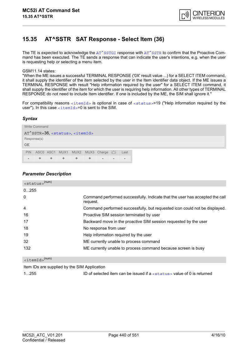
MC52i AT Command Set 15.35 AT^SSTR
MC52i_ATC_V01.201 Page 440 of 551 4/16/10Confidential / Released
15.35 AT^SSTR SAT Response - Select Item (36)
The TE is expected to acknowledge the AT^SSTGI response with AT^SSTR to confirm that the Proactive Com-mand has been executed. The TE sends a response that can indicate the user's intentions, e.g. when the useris requesting help or selecting a menu item.
GSM11.14 states:"When the ME issues a successful TERMINAL RESPONSE ('0X' result value ...) for a SELECT ITEM command,it shall supply the identifier of the item selected by the user in the Item identifier data object. If the ME issues aTERMINAL RESPONSE with result "Help information required by the user" for a SELECT ITEM command, itshall supply the identifier of the item for which the user is requiring help information. All other types of TERMINALRESPONSE do not need to include Item identifier. If one is included by the ME, the SIM shall ignore it."
For compatibility reasons <itemId> is optional in case of <status>=19 ("Help information required by theuser"). In this case <itemId>=0 is sent to the SIM.
Syntax
Parameter Description
0...255
0 Command performed successfully. Indicate that the user has accepted the callrequest.
4 Command performed successfully, but requested icon could not be displayed.
16 Proactive SIM session terminated by user
17 Backward move in the proactive SIM session requested by the user
18 No response from user
19 Help information required by the user
32 ME currently unable to process command
132 ME currently unable to process command because screen is busy
Item IDs are supplied by the SIM Application
1...255 ID of selected item can be issued if a <status> value of 0 is returned
Write Command
AT^SSTR=36, <status>, <itemId>Response(s)
OK
PIN ASC0 ASC1 MUX1 MUX2 MUX3 Charge Last
- + + + + + - - -
<status>(num)
<itemId>(num)

MC52i AT Command Set 15.36 AT^SSTR
MC52i_ATC_V01.201 Page 441 of 551 4/16/10Confidential / Released
15.36 AT^SSTR SAT Response - Setup Menu (37)
The TE is expected to acknowledge the AT^SSTGI response with AT^SSTR to confirm that the Proactive Com-mand has been executed.
Syntax
Parameter Description
0...255
0 Command performed successfully. Indicate that the user has accepted the callrequest.
4 Command performed successfully, but requested icon could not be displayed.
32 ME currently unable to process command
132 ME currently unable to process command because screen is busy
Note• The response simply conveys, to the SAT, the information that the main menu was received and set up on
the user interface. It does not transmit any information about a selected item, like in the case of AT^SSTR.
Once this command was executed the user can proceed as described in the AT^SSTR SAT Response - SetupMenu (37).
Write Command
AT^SSTR=37, <status>Response(s)
OK
PIN ASC0 ASC1 MUX1 MUX2 MUX3 Charge Last
- + + + + + - - -
<status>(num)

MC52i AT Command Set 15.37 AT^SSTR
MC52i_ATC_V01.201 Page 442 of 551 4/16/10Confidential / Released
15.37 AT^SSTR SAT Response - Set Up Idle Mode Text (40)
The TE is expected to acknowledge the AT^SSTGI response with AT^SSTR to confirm that the Proactive Com-mand has been executed.
Syntax
Parameter Description
0...255
0 Command performed successfully. Indicate that the user has accepted the callrequest.
32 ME currently unable to process command
132 ME currently unable to process command because screen is busy
Write Command
AT^SSTR=40, <status>Response(s)
OK
PIN ASC0 ASC1 MUX1 MUX2 MUX3 Charge Last
- + + + + + - - -
<status>(num)

MC52i AT Command Set 15.38 AT^SSTR
MC52i_ATC_V01.201 Page 443 of 551 4/16/10Confidential / Released
15.38 AT^SSTR SAT Event - Menu Selection (211)
The TE specifies the user's selection of an item from the main menu, which was set up using SETUP MENUcommand. Alternatively help can be requested.
Syntax
Parameter Description
0...255
0 Command performed successfully.
19 Help information required by the user, no other value can be returned.
ID of selected item
0...255
Write Command
AT^SSTR=211, <status>, <itemId>Response(s)
OK
PIN ASC0 ASC1 MUX1 MUX2 MUX3 Charge Last
- + + + + + - - -
<status>(num)
<itemId>(num)
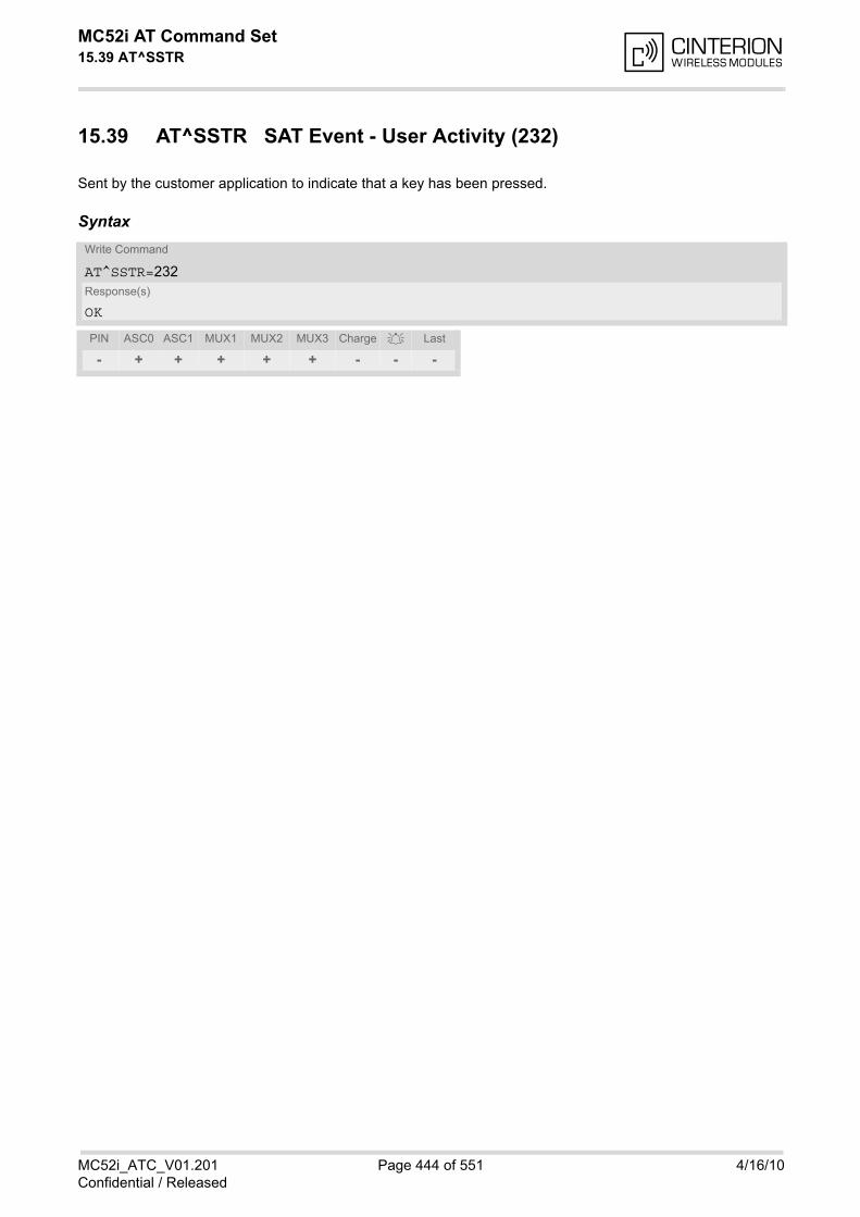
MC52i AT Command Set 15.39 AT^SSTR
MC52i_ATC_V01.201 Page 444 of 551 4/16/10Confidential / Released
15.39 AT^SSTR SAT Event - User Activity (232)
Sent by the customer application to indicate that a key has been pressed.
SyntaxWrite Command
AT^SSTR=232Response(s)
OK
PIN ASC0 ASC1 MUX1 MUX2 MUX3 Charge Last
- + + + + + - - -
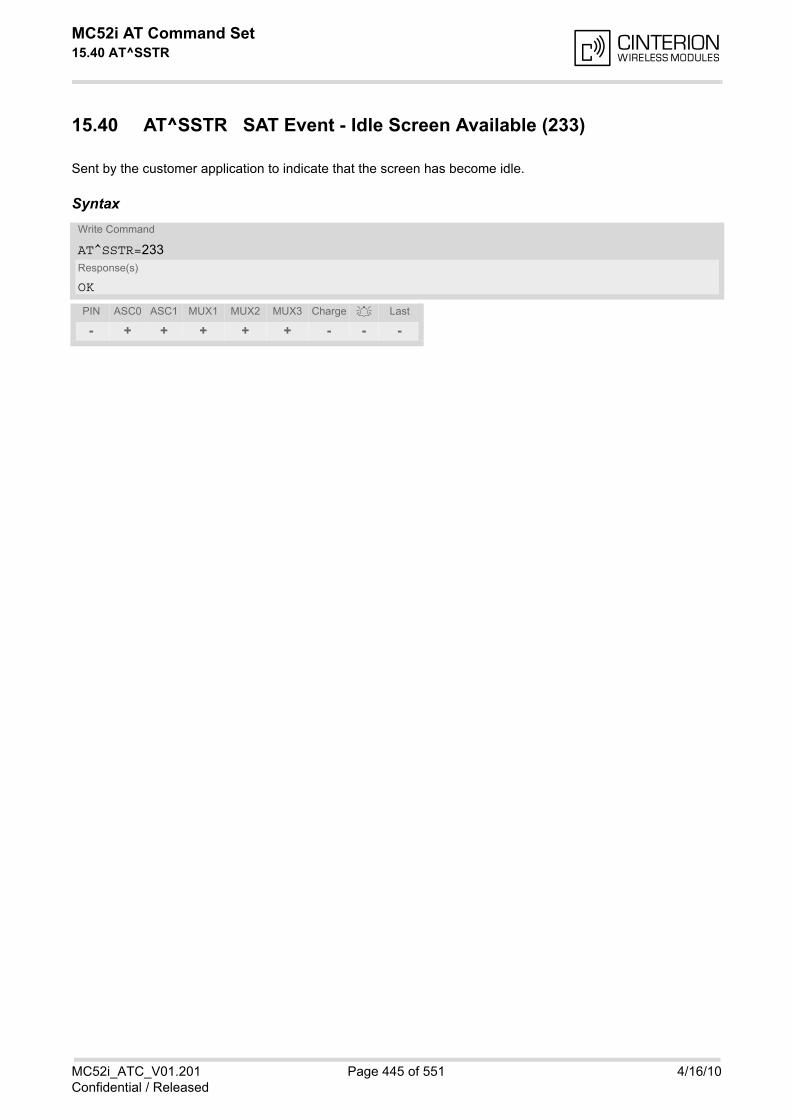
MC52i AT Command Set 15.40 AT^SSTR
MC52i_ATC_V01.201 Page 445 of 551 4/16/10Confidential / Released
15.40 AT^SSTR SAT Event - Idle Screen Available (233)
Sent by the customer application to indicate that the screen has become idle.
SyntaxWrite Command
AT^SSTR=233Response(s)
OK
PIN ASC0 ASC1 MUX1 MUX2 MUX3 Charge Last
- + + + + + - - -
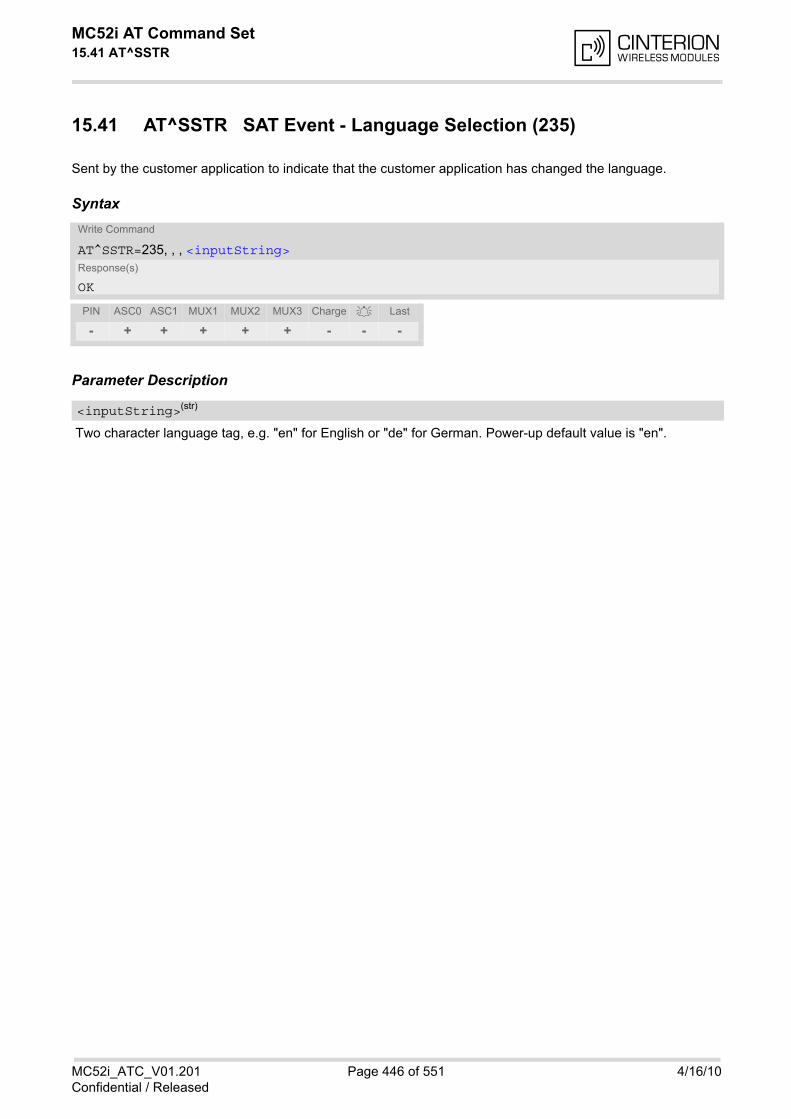
MC52i AT Command Set 15.41 AT^SSTR
MC52i_ATC_V01.201 Page 446 of 551 4/16/10Confidential / Released
15.41 AT^SSTR SAT Event - Language Selection (235)
Sent by the customer application to indicate that the customer application has changed the language.
Syntax
Parameter Description
Two character language tag, e.g. "en" for English or "de" for German. Power-up default value is "en".
Write Command
AT^SSTR=235, , , <inputString>Response(s)
OK
PIN ASC0 ASC1 MUX1 MUX2 MUX3 Charge Last
- + + + + + - - -
<inputString>(str)
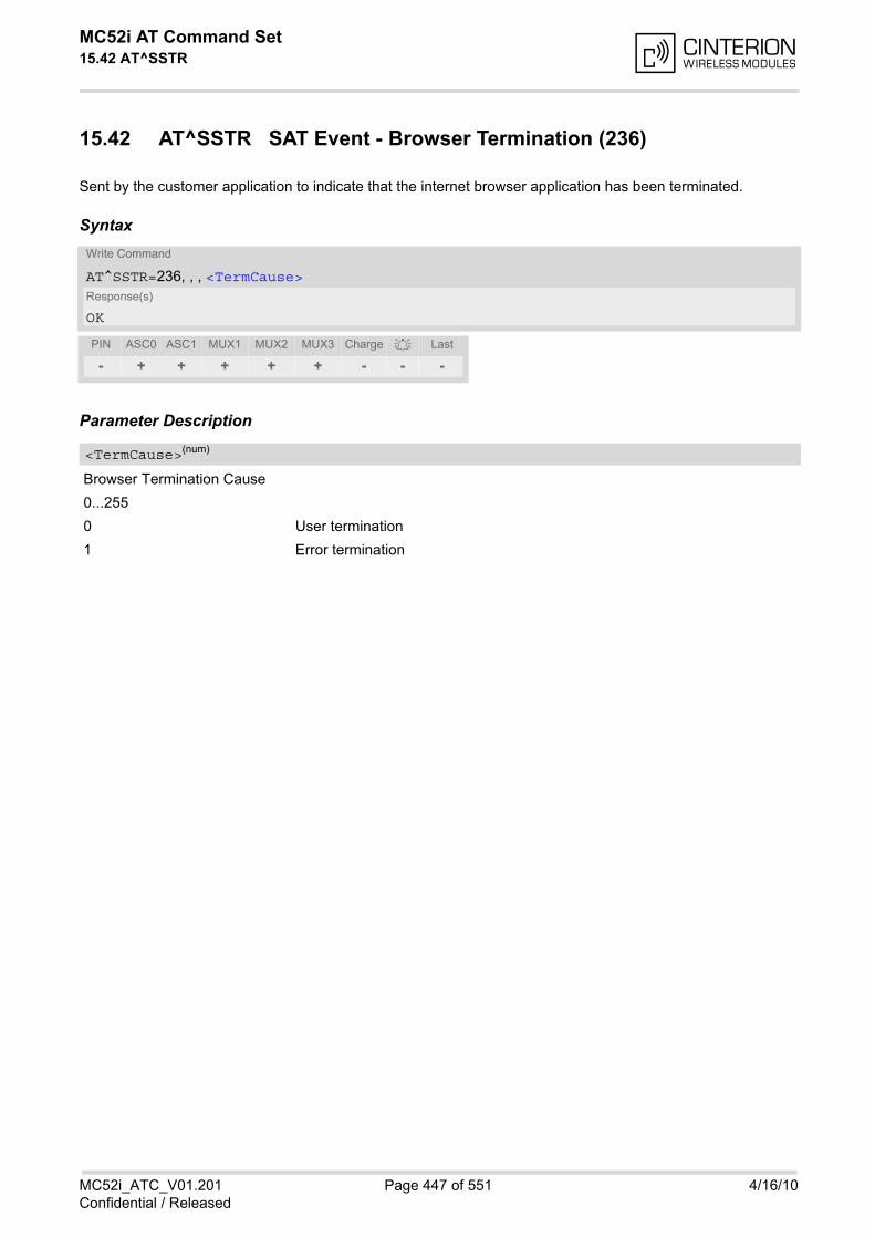
MC52i AT Command Set 15.42 AT^SSTR
MC52i_ATC_V01.201 Page 447 of 551 4/16/10Confidential / Released
15.42 AT^SSTR SAT Event - Browser Termination (236)
Sent by the customer application to indicate that the internet browser application has been terminated.
Syntax
Parameter Description
Browser Termination Cause
0...255
0 User termination
1 Error termination
Write Command
AT^SSTR=236, , , <TermCause>Response(s)
OK
PIN ASC0 ASC1 MUX1 MUX2 MUX3 Charge Last
- + + + + + - - -
<TermCause>(num)
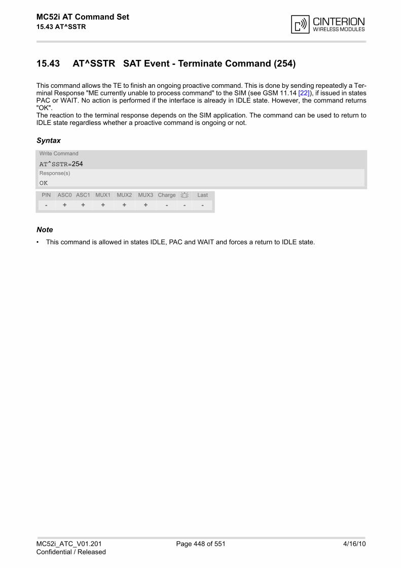
MC52i AT Command Set 15.43 AT^SSTR
MC52i_ATC_V01.201 Page 448 of 551 4/16/10Confidential / Released
15.43 AT^SSTR SAT Event - Terminate Command (254)
This command allows the TE to finish an ongoing proactive command. This is done by sending repeatedly a Ter-minal Response "ME currently unable to process command" to the SIM (see GSM 11.14 [22]), if issued in statesPAC or WAIT. No action is performed if the interface is already in IDLE state. However, the command returns"OK".The reaction to the terminal response depends on the SIM application. The command can be used to return toIDLE state regardless whether a proactive command is ongoing or not.
Syntax
Note• This command is allowed in states IDLE, PAC and WAIT and forces a return to IDLE state.
Write Command
AT^SSTR=254Response(s)
OK
PIN ASC0 ASC1 MUX1 MUX2 MUX3 Charge Last
- + + + + + - - -
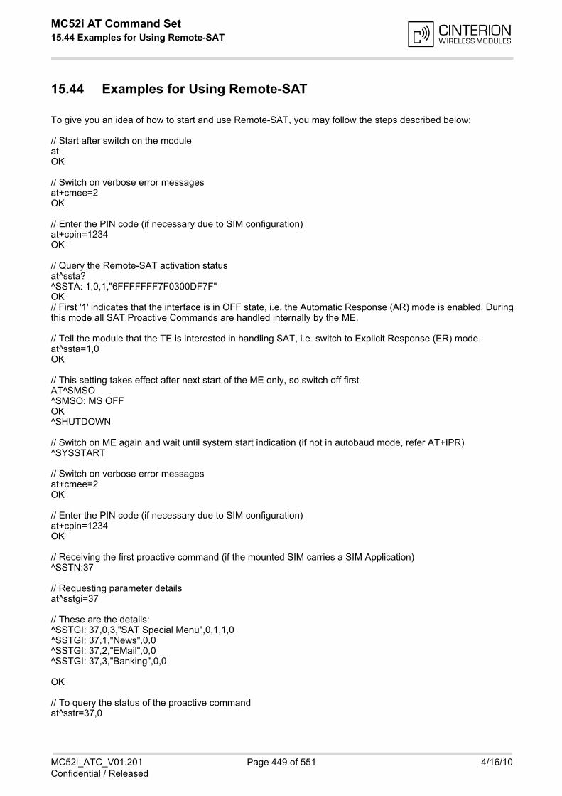
MC52i AT Command Set 15.44 Examples for Using Remote-SAT
MC52i_ATC_V01.201 Page 449 of 551 4/16/10Confidential / Released
15.44 Examples for Using Remote-SAT
To give you an idea of how to start and use Remote-SAT, you may follow the steps described below:
// Start after switch on the moduleatOK
// Switch on verbose error messagesat+cmee=2OK
// Enter the PIN code (if necessary due to SIM configuration)at+cpin=1234OK
// Query the Remote-SAT activation statusat^ssta?^SSTA: 1,0,1,"6FFFFFFF7F0300DF7F" OK// First '1' indicates that the interface is in OFF state, i.e. the Automatic Response (AR) mode is enabled. Duringthis mode all SAT Proactive Commands are handled internally by the ME.
// Tell the module that the TE is interested in handling SAT, i.e. switch to Explicit Response (ER) mode.at^ssta=1,0OK
// This setting takes effect after next start of the ME only, so switch off firstAT^SMSO^SMSO: MS OFFOK ^SHUTDOWN
// Switch on ME again and wait until system start indication (if not in autobaud mode, refer AT+IPR)^SYSSTART
// Switch on verbose error messagesat+cmee=2OK
// Enter the PIN code (if necessary due to SIM configuration)at+cpin=1234OK
// Receiving the first proactive command (if the mounted SIM carries a SIM Application)^SSTN:37
// Requesting parameter detailsat^sstgi=37
// These are the details:^SSTGI: 37,0,3,"SAT Special Menu",0,1,1,0^SSTGI: 37,1,"News",0,0^SSTGI: 37,2,"EMail",0,0^SSTGI: 37,3,"Banking",0,0
OK
// To query the status of the proactive commandat^sstr=37,0
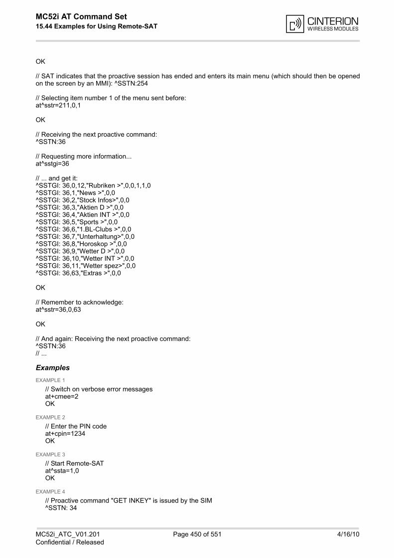
MC52i AT Command Set 15.44 Examples for Using Remote-SAT
MC52i_ATC_V01.201 Page 450 of 551 4/16/10Confidential / Released
OK
// SAT indicates that the proactive session has ended and enters its main menu (which should then be openedon the screen by an MMI): ^SSTN:254
// Selecting item number 1 of the menu sent before:at^sstr=211,0,1
OK
// Receiving the next proactive command:^SSTN:36
// Requesting more information...at^sstgi=36
// ... and get it:^SSTGI: 36,0,12,"Rubriken >",0,0,1,1,0^SSTGI: 36,1,"News >",0,0^SSTGI: 36,2,"Stock Infos>",0,0^SSTGI: 36,3,"Aktien D >",0,0^SSTGI: 36,4,"Aktien INT >",0,0^SSTGI: 36,5,"Sports >",0,0^SSTGI: 36,6,"1.BL-Clubs >",0,0^SSTGI: 36,7,"Unterhaltung>",0,0^SSTGI: 36,8,"Horoskop >",0,0^SSTGI: 36,9,"Wetter D >",0,0^SSTGI: 36,10,"Wetter INT >",0,0^SSTGI: 36,11,"Wetter spez>",0,0^SSTGI: 36,63,"Extras >",0,0
OK
// Remember to acknowledge:at^sstr=36,0,63
OK
// And again: Receiving the next proactive command:^SSTN:36// ...
ExamplesEXAMPLE 1
// Switch on verbose error messagesat+cmee=2OK
EXAMPLE 2
// Enter the PIN codeat+cpin=1234OK
EXAMPLE 3
// Start Remote-SATat^ssta=1,0OK
EXAMPLE 4
// Proactive command "GET INKEY" is issued by the SIM^SSTN: 34
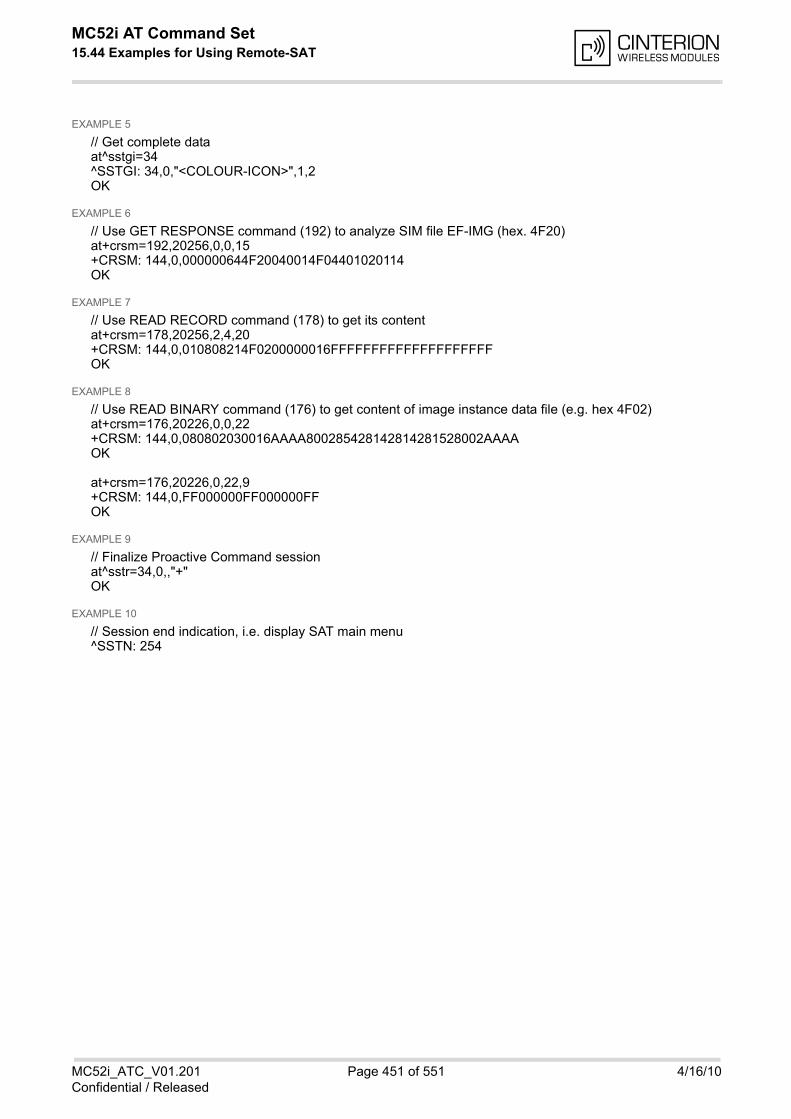
MC52i AT Command Set 15.44 Examples for Using Remote-SAT
MC52i_ATC_V01.201 Page 451 of 551 4/16/10Confidential / Released
EXAMPLE 5
// Get complete dataat^sstgi=34^SSTGI: 34,0,"<COLOUR-ICON>",1,2OK
EXAMPLE 6
// Use GET RESPONSE command (192) to analyze SIM file EF-IMG (hex. 4F20)at+crsm=192,20256,0,0,15+CRSM: 144,0,000000644F20040014F04401020114OK
EXAMPLE 7
// Use READ RECORD command (178) to get its contentat+crsm=178,20256,2,4,20+CRSM: 144,0,010808214F0200000016FFFFFFFFFFFFFFFFFFFFOK
EXAMPLE 8
// Use READ BINARY command (176) to get content of image instance data file (e.g. hex 4F02)at+crsm=176,20226,0,0,22+CRSM: 144,0,080802030016AAAA800285428142814281528002AAAAOK
at+crsm=176,20226,0,22,9+CRSM: 144,0,FF000000FF000000FFOK
EXAMPLE 9
// Finalize Proactive Command sessionat^sstr=34,0,,"+"OK
EXAMPLE 10
// Session end indication, i.e. display SAT main menu^SSTN: 254
MC52i AT Command Set 16. Phonebook Commands
MC52i_ATC_V01.201 Page 452 of 551 4/16/10Confidential / Released
16. Phonebook Commands
The AT commands described in this chapter allow the external application to access the phonebooks located inthe MC52i's memory or on the attached Subscriber Identity Module (SIM).
16.1 Sort Order for Phonebooks
Due to the support of UCS2 for the <text> part of phonebook entries, the sort order for phonebook records fol-lows the algorithm published as Unicode Technical Standard #10, "Unicode Collation Algorithm".A memory-optimized version of the proposed collation tables "[AllKeys]" from Unicode Technical Standard #10is used in order to determine collation weights for Code points between 0000 and 06FF, and composed keys areused for Code points from ranges 0700 to 33FF, A000 to D7FF and E000 to FFFD. Code Points not referencedin these tables will be assigned a default collation weight with their unicode value as level 1 weight. Decomposi-tion is not supported.Phonebook entries whose names contain only characters from the GSM07.07 default alphabet are convertedinternally into their UCS2 equivalents in order to achieve consistent sorting results.
For the user, this means that:
• Punctuation marks and other non-alphabetical characters from the common latin-based character sets, andfrom the standard GSM character set, will be sorted before any alphabetical characters. The ordering in whichthese marks appear as compared to other non-alphabetical characters from the same group is determinedby their collation weights and does not reflect their code values in the UCS2 or GSM alphabet tables above.Please refer to www.unicode.org for detail.
• Alphabetical characters from the common latin-based character sets, and from the standard GSM characterset, will be sorted according to their underlying base characters, plus the collation weights of their accentsigns.
• Only collation levels 1 and 2 are regarded, so sorting is not case-sensitive.
Example: the european letters "Å" (GSM 0EH, UCS2 00C5h), "æ" (GSM 1DH, UCS2 00E6h), "ç" (GSM09h,UCS2 00E7h), "a" (GSM 61H, UCS2 0061h ) and "b" (GSM 62H, UCS2 0062h) will be sorted in order "a", "Å","æ" "b","ç" although their numerical values in GSM and UCS2 suggest a different ordering.

MC52i AT Command Set 16.2 AT+CPBR
MC52i_ATC_V01.201 Page 453 of 551 4/16/10Confidential / Released
16.2 AT+CPBR Read from Phonebook
AT+CPBR serves to read one or more entries from the phonebook selected with AT command AT+CPBS.
The AT+CPBR test command returns the location range supported by the current phonebook storage, the maxi-mum length of <number> field and the maximum length of <text> field.Note: Length information may not be available while SIM storage is selected. If storage does not offer formatinformation, the format list contains empty parenthesizes.
The AT+CPBR write command determines the phonebook entry to be displayed with <location1> or a locationrange from <location1> to <location2>. Hence, if no <location2> is given only the entry at<location1> will be displayed. If no entries are found at the selected location "OK" will be returned.
Syntax
Parameter Description
The first (lowest) location number within phonebook memory where to start reading. The maximum range sup-ported by the current phonebook is given in the test command response. If <location1> exceeds the upper bound <maxloc> (as indicated by the test command), command willrespond with "+CME ERROR: invalid index".
The last (highest) location number within phonebook memory where to stop reading. The maximum range sup-ported by the current phonebook is given in the test command response. If both <location1> and <location2> are in the range indicated by the test command parameter <max-loc>, the list of entries will be output and terminated with "OK". If <location2> exceeds the range indicated by the test command parameter <maxloc>, the list of entries willbe output but terminated with "+CME ERROR: invalid index".
Phone number in format specified by <type>, it may be an empty string.
Test Command
AT+CPBR=?Response(s)
+CPBR: (1-<maxloc>), <nlength>, <tlength>OKERROR+CME ERROR: <err>
Write Command
AT+CPBR=<location1>[, <location2>]Response(s)
[+CPBR: <location1>, <number>, <type>, <text>][+CPBR: <location2>, <number>, <type>, <text>]OKERROR+CME ERROR: <err>
PIN ASC0 ASC1 MUX1 MUX2 MUX3 Charge Last Reference(s)
+ + + + + + - - - GSM 07.07, GSM 11.11
<location1>(num)
<location2>(num)
<number>(str)
MC52i AT Command Set 16.2 AT+CPBR
MC52i_ATC_V01.201 Page 454 of 551 4/16/10Confidential / Released
Type of address octet, which defines the used type of number (ton) and the numbering plan identification (npi).Please consider that for types other than 129 or 145 dialing from phonebook with ATD><mem><n> is, dependingon the network, not always possible (refer to GSM 04.08 subclause 10.5.4.7 for details). See also <type> ofAT+CPBW. Possible values are:
145 Dialing string <number> includes international access code character '+'
161 National number. Network support of this type is optional.
209 Dialing string <number> has been saved as ASCII string and includes non-digit characters other than "*", "#" or "+". Note that phonebook entries savedwith this type cannot be dialed.
255 Dialing string <number> is a command to control a Supplementary Service,i.e. "*", "#" codes are contained. Network support of this type is optional.
129 Otherwise
Text assigned to a phone number. The maximum length for this parameter is given with test command responseparameter <tlength>. If using an ASCII terminal characters which are coded differently in ASCII and GSM have to be entered viaescape sequences as described in Section 1.6, Supported character sets.
Maximum location number for the currently selected storage. For phonebooks located on the SIM this valuedepends on the SIM card type.
Maximum length of phone number for "normal" locations. Depending on the storage a limited number of loca-tions with extended memory is available per phonebook. These locations allow storing numbers with twice thestandard length, which is 2*<nlength> digits for normal numbers, but only <nlength> digits for numberssaved with <type>=209.
Maximum length of <text> assigned to the telephone number. The value indicated by the test command isgiven in octets. If <text> is given as GSM characters each character corresponds to one octet. If the <text>string is given in UCS2, the maximum number of characters depends on the coding scheme used for the alphafield of the SIM according to GSM 11.11, Annex B [21]. In the worst case the number of UCS2 characters is atleast one less than half the number of GSM characters.
Note• Users should be aware that when using this AT command quickly after SIM PIN authentication the SIM data
may not yet be accessible, resulting in a short delay before the requested AT command response is returned.See Section 20.1, Restricted access to SIM data after SIM PIN authentication for further detail.
<type>(num)
<text>(str)(+CSCS)
<maxloc>(num)
<nlength>(num)
<tlength>(num)
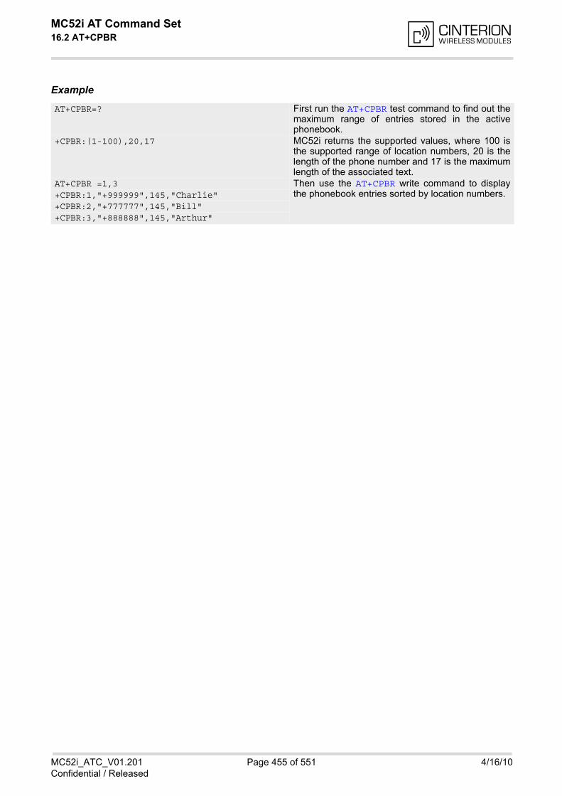
MC52i AT Command Set 16.2 AT+CPBR
MC52i_ATC_V01.201 Page 455 of 551 4/16/10Confidential / Released
Example
AT+CPBR=? First run the AT+CPBR test command to find out themaximum range of entries stored in the activephonebook.
+CPBR:(1-100),20,17 MC52i returns the supported values, where 100 isthe supported range of location numbers, 20 is thelength of the phone number and 17 is the maximumlength of the associated text.
AT+CPBR =1,3 Then use the AT+CPBR write command to displaythe phonebook entries sorted by location numbers. +CPBR:1,"+999999",145,"Charlie"
+CPBR:2,"+777777",145,"Bill" +CPBR:3,"+888888",145,"Arthur"
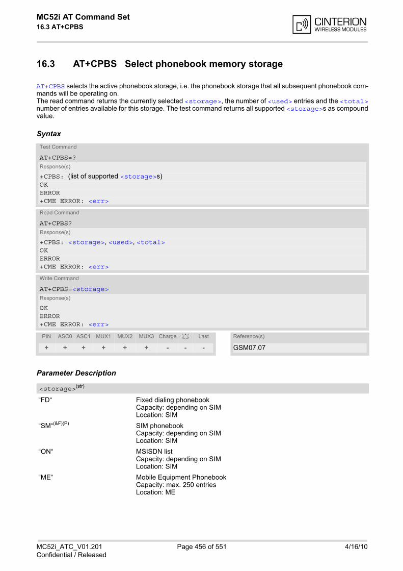
MC52i AT Command Set 16.3 AT+CPBS
MC52i_ATC_V01.201 Page 456 of 551 4/16/10Confidential / Released
16.3 AT+CPBS Select phonebook memory storage
AT+CPBS selects the active phonebook storage, i.e. the phonebook storage that all subsequent phonebook com-mands will be operating on.The read command returns the currently selected <storage>, the number of <used> entries and the <total>number of entries available for this storage. The test command returns all supported <storage>s as compoundvalue.
Syntax
Parameter Description
“FD“ Fixed dialing phonebookCapacity: depending on SIMLocation: SIM
“SM“(&F)(P) SIM phonebookCapacity: depending on SIMLocation: SIM
“ON“ MSISDN listCapacity: depending on SIMLocation: SIM
“ME“ Mobile Equipment PhonebookCapacity: max. 250 entriesLocation: ME
Test Command
AT+CPBS=?Response(s)
+CPBS: (list of supported <storage>s)OKERROR+CME ERROR: <err>
Read Command
AT+CPBS?Response(s)
+CPBS: <storage>, <used>, <total>OKERROR+CME ERROR: <err>
Write Command
AT+CPBS=<storage>Response(s)
OKERROR+CME ERROR: <err>
PIN ASC0 ASC1 MUX1 MUX2 MUX3 Charge Last Reference(s)
+ + + + + + - - - GSM07.07
<storage>(str)
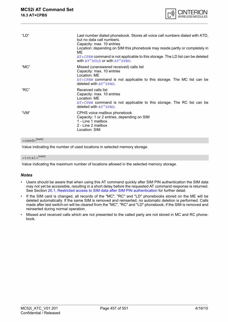
MC52i AT Command Set 16.3 AT+CPBS
MC52i_ATC_V01.201 Page 457 of 551 4/16/10Confidential / Released
“LD“ Last number dialed phonebook. Stores all voice call numbers dialed with ATD,but no data call numbers.Capacity: max. 10 entriesLocation: depending on SIM this phonebook may reside partly or completely inMEAT+CPBW command is not applicable to this storage. The LD list can be deletedwith AT^SDLD or with AT^SPBD.
“MC“ Missed (unanswered received) calls listCapacity: max. 10 entriesLocation: MEAT+CPBW command is not applicable to this storage. The MC list can bedeleted with AT^SPBD.
“RC“ Received calls listCapacity: max. 10 entriesLocation: MEAT+CPBW command is not applicable to this storage. The RC list can bedeleted with AT^SPBD.
“VM“ CPHS voice mailbox phonebookCapacity: 1 or 2 entries, depending on SIM1 - Line 1 mailbox2 - Line 2 mailboxLocation: SIM
Value indicating the number of used locations in selected memory storage.
Value indicating the maximum number of locations allowed in the selected memory storage.
Notes• Users should be aware that when using this AT command quickly after SIM PIN authentication the SIM data
may not yet be accessible, resulting in a short delay before the requested AT command response is returned.See Section 20.1, Restricted access to SIM data after SIM PIN authentication for further detail.
• If the SIM card is changed, all records of the "MC", "RC" and "LD" phonebooks stored on the ME will bedeleted automatically. If the same SIM is removed and reinserted, no automatic deletion is performed. Callsmade after last switch-on will be cleared from the "MC", "RC" and "LD" phonebook, if the SIM is removed andreinserted during normal operation.
• Missed and received calls which are not presented to the called party are not stored in MC and RC phone-book.
<used>(num)
<total>(num)

MC52i AT Command Set 16.4 AT+CPBW
MC52i_ATC_V01.201 Page 458 of 551 4/16/10Confidential / Released
16.4 AT+CPBW Write into Phonebook
The AT+CPBW write command can be used to create, edit and delete a phonebook entry at a <location> ofthe active storage selected with AT+CPBS.If <storage>="FD" (SIM fixed dialing numbers) is selected, PIN2 authentication has to be performed prior toany write access.
The AT+CPBW test command returns the location range supported by the current storage, the maximum lengthof the <number> field, the range of supported <type> values and the maximum length of the <text> field.Note: The length may not be available while SIM storage is selected. If storage does not offer format information,the format list contains empty parenthesizes.
Syntax
Parameter Description
Location number within phonebook memory. The maximum range supported by each storage type is indicatedin the test command response. If <location> is not given, the first free entry will be used.If <location> is given as the only parameter, the phonebook entry specified by <location> is deleted.
Phone number in format specified by <type>. Parameter must be present, although it may be an empty string.Alphabetic characters are not permitted. <number> may contain dialstring modifiers "*", "#" or "+".If other printable non-alphabetic characters are used the entry needs to be saved with <type>=209. Otherwise,if <type>=209 is not used any non-digit characters other than "*", "#" or "+" will be removed from the string andonly accepted modifiers from the GSM alphabet will be saved.A <number> saved with <type>=209 requires double memory. In order to fit into a standard location, the num-ber needs to be reduced to a maximum length of <nlength>/2, including all digits and dial string modifiers.Extended locations may be used as stated below for <nlength>.
Test Command
AT+CPBW=?Response(s)
+CPBW: (1-<maxloc>), <nlength>, (list of supported <type>s), <tlength>OKERROR+CME ERROR: <err>
Write Command
AT+CPBW=[<location>][, <number>[[, <type>][, <text>]]]Response(s)
OKERROR+CME ERROR: <err>
PIN ASC0 ASC1 MUX1 MUX2 MUX3 Charge Last Reference(s)
+ + + + + + - - - GSM 07.07, GSM 04.08
<location>(num)
<number>(str)
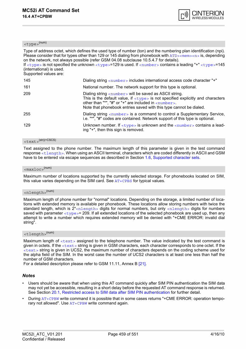
MC52i AT Command Set 16.4 AT+CPBW
MC52i_ATC_V01.201 Page 459 of 551 4/16/10Confidential / Released
Type of address octet, which defines the used type of number (ton) and the numbering plan identification (npi).Please consider that for types other than 129 or 145 dialing from phonebook with ATD><mem><n> is, dependingon the network, not always possible (refer GSM 04.08 subclause 10.5.4.7 for details).If <type> is not specified the unknown <type>=129 is used. If <number> contains a leading "+" <type>=145(international) is used.Supported values are:
145 Dialing string <number> includes international access code character "+"
161 National number. The network support for this type is optional.
209 Dialing string <number> will be saved as ASCII string.This is the default value, if <type> is not specified explicitly and charactersother than "*", "#" or "+" are included in <number>.Note that phonebook entries saved with this type cannot be dialed.
255 Dialing string <number> is a command to control a Supplementary Service,i.e. "*", "#" codes are contained. Network support of this type is optional.
129 Unknown number. If <type> is unknown and the <number> contains a lead-ing "+", then this sign is removed.
Text assigned to the phone number. The maximum length of this parameter is given in the test commandresponse <tlength>. When using an ASCII terminal, characters which are coded differently in ASCII and GSMhave to be entered via escape sequences as described in Section 1.6, Supported character sets.
Maximum number of locations supported by the currently selected storage. For phonebooks located on SIM,this value varies depending on the SIM card. See AT+CPBS for typical values.
Maximum length of phone number for "normal" locations. Depending on the storage, a limited number of loca-tions with extended memory is available per phonebook. These locations allow storing numbers with twice thestandard length, which is 2*<nlength> digits for normal numbers, but only <nlength> digits for numberssaved with parameter <type>= 209. If all extended locations of the selected phonebook are used up, then anyattempt to write a number which requires extended memory will be denied with "+CME ERROR: invalid dialstring".
Maximum length of <text> assigned to the telephone number. The value indicated by the test command isgiven in octets. If the <text> string is given in GSM characters, each character corresponds to one octet. If the<text> string is given in UCS2, the maximum number of characters depends on the coding scheme used forthe alpha field of the SIM. In the worst case the number of UCS2 characters is at least one less than half thenumber of GSM characters.For a detailed description please refer to GSM 11.11, Annex B [21].
Notes• Users should be aware that when using this AT command quickly after SIM PIN authentication the SIM data
may not yet be accessible, resulting in a short delay before the requested AT command response is returned.See Section 20.1, Restricted access to SIM data after SIM PIN authentication for further detail.
• During AT+CPBW write command it is possible that in some cases returns "+CME ERROR: operation tempo-rary not allowed". Use AT+CPBW write command again.
<type>(num)
<text>(str)(+CSCS)
<maxloc>(num)
<nlength>(num)
<tlength>(num)
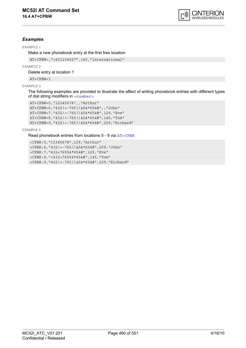
MC52i AT Command Set 16.4 AT+CPBW
MC52i_ATC_V01.201 Page 460 of 551 4/16/10Confidential / Released
ExamplesEXAMPLE 1
Make a new phonebook entry at the first free location
EXAMPLE 2
Delete entry at location 1
EXAMPLE 3
The following examples are provided to illustrate the effect of writing phonebook entries with different typesof dial string modifiers in <number>
EXAMPLE 4
Read phonebook entries from locations 5 - 9 via AT+CPBR
AT+CPBW=,"+431234567",145,"international"
AT+CPBW=1
AT+CPBW=5,"12345678",,"Arthur" AT+CPBW=6,"432!+-765()&54*654#",,"John" AT+CPBW=7,"432!+-765()&54*654#",129,"Eve" AT+CPBW=8,"432!+-765()&54*654#",145,"Tom" AT+CPBW=9,"432!+-765()&54*654#",209,"Richard"
+CPBR:5,"12345678",129,"Arthur" +CPBR:6,"432!+-765()&54*654#",209,"John" +CPBR:7,"432+76554*654#",129,"Eve" +CPBR:8,"+432+76554*654#",145,"Tom" +CPBR:9,"432!+-765()&54*654#",209,"Richard"
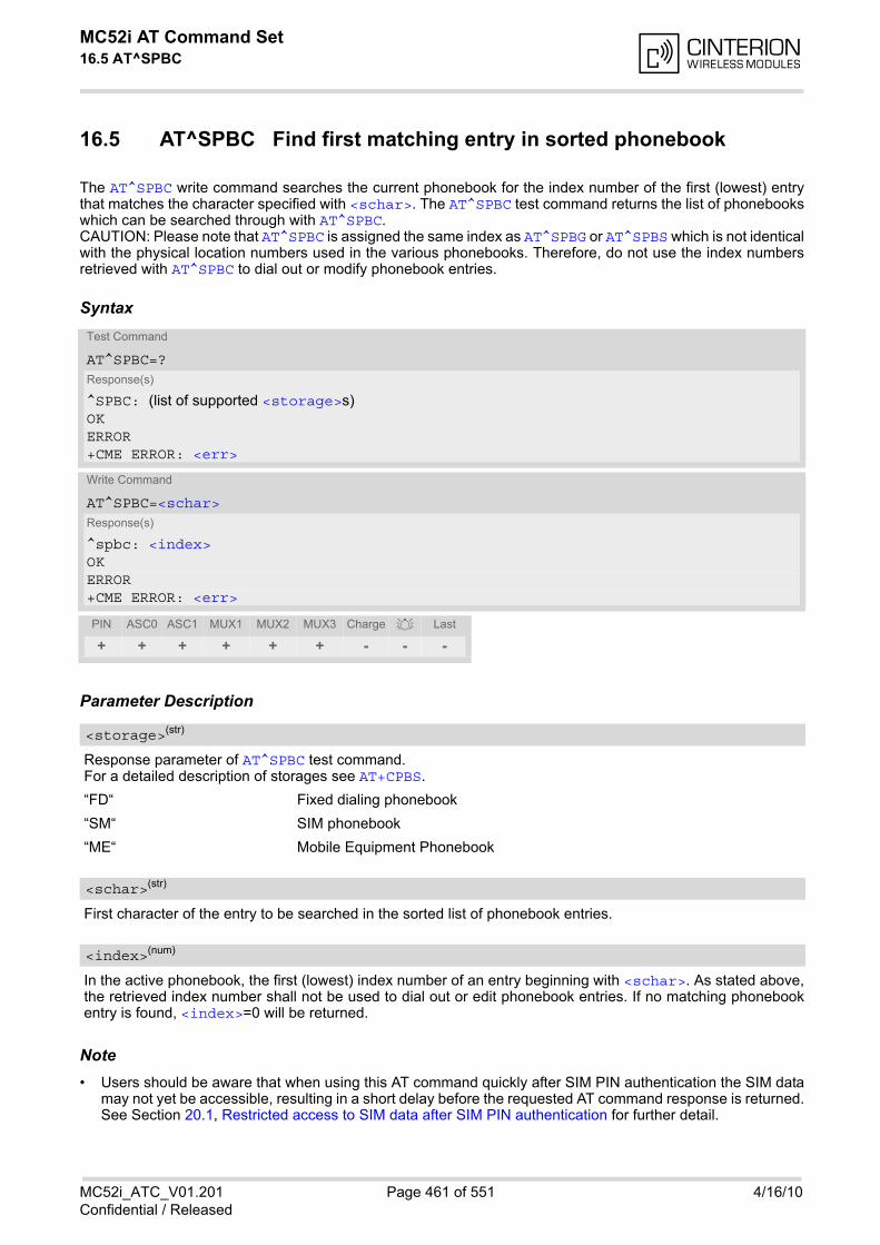
MC52i AT Command Set 16.5 AT^SPBC
MC52i_ATC_V01.201 Page 461 of 551 4/16/10Confidential / Released
16.5 AT^SPBC Find first matching entry in sorted phonebook
The AT^SPBC write command searches the current phonebook for the index number of the first (lowest) entrythat matches the character specified with <schar>. The AT^SPBC test command returns the list of phonebookswhich can be searched through with AT^SPBC.CAUTION: Please note that AT^SPBC is assigned the same index as AT^SPBG or AT^SPBS which is not identicalwith the physical location numbers used in the various phonebooks. Therefore, do not use the index numbersretrieved with AT^SPBC to dial out or modify phonebook entries.
Syntax
Parameter Description
Response parameter of AT^SPBC test command. For a detailed description of storages see AT+CPBS.
“FD“ Fixed dialing phonebook
“SM“ SIM phonebook
“ME“ Mobile Equipment Phonebook
First character of the entry to be searched in the sorted list of phonebook entries.
In the active phonebook, the first (lowest) index number of an entry beginning with <schar>. As stated above,the retrieved index number shall not be used to dial out or edit phonebook entries. If no matching phonebookentry is found, <index>=0 will be returned.
Note• Users should be aware that when using this AT command quickly after SIM PIN authentication the SIM data
may not yet be accessible, resulting in a short delay before the requested AT command response is returned.See Section 20.1, Restricted access to SIM data after SIM PIN authentication for further detail.
Test Command
AT^SPBC=?Response(s)
^SPBC: (list of supported <storage>s)OKERROR+CME ERROR: <err>
Write Command
AT^SPBC=<schar>Response(s)
^spbc: <index>OKERROR+CME ERROR: <err>
PIN ASC0 ASC1 MUX1 MUX2 MUX3 Charge Last
+ + + + + + - - -
<storage>(str)
<schar>(str)
<index>(num)
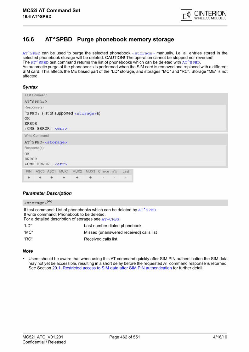
MC52i AT Command Set 16.6 AT^SPBD
MC52i_ATC_V01.201 Page 462 of 551 4/16/10Confidential / Released
16.6 AT^SPBD Purge phonebook memory storage
AT^SPBD can be used to purge the selected phonebook <storage> manually, i.e. all entries stored in theselected phonebook storage will be deleted. CAUTION! The operation cannot be stopped nor reversed!The AT^SPBD test command returns the list of phonebooks which can be deleted with AT^SPBD.An automatic purge of the phonebooks is performed when the SIM card is removed and replaced with a differentSIM card. This affects the ME based part of the "LD" storage, and storages "MC" and "RC". Storage "ME" is notaffected.
Syntax
Parameter Description
If test command: List of phonebooks which can be deleted by AT^SPBD.If write command: Phonebook to be deleted.For a detailed description of storages see AT+CPBS.
“LD“ Last number dialed phonebook
“MC“ Missed (unanswered received) calls list
“RC“ Received calls list
Note• Users should be aware that when using this AT command quickly after SIM PIN authentication the SIM data
may not yet be accessible, resulting in a short delay before the requested AT command response is returned.See Section 20.1, Restricted access to SIM data after SIM PIN authentication for further detail.
Test Command
AT^SPBD=?Response(s)
^SPBD: (list of supported <storage>s)OKERROR+CME ERROR: <err>
Write Command
AT^SPBD=<storage>Response(s)
OKERROR+CME ERROR: <err>
PIN ASC0 ASC1 MUX1 MUX2 MUX3 Charge Last
+ + + + + + - - -
<storage>(str)
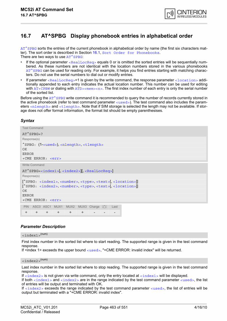
MC52i AT Command Set 16.7 AT^SPBG
MC52i_ATC_V01.201 Page 463 of 551 4/16/10Confidential / Released
16.7 AT^SPBG Display phonebook entries in alphabetical order
AT^SPBG sorts the entries of the current phonebook in alphabetical order by name (the first six characters mat-ter). The sort order is described in Section 16.1, Sort Order for Phonebooks.There are two ways to use AT^SPBG:
• If the optional parameter <RealLocReq> equals 0 or is omitted the sorted entries will be sequentially num-bered. As these numbers are not identical with the location numbers stored in the various phonebooksAT^SPBG can be used for reading only. For example, it helps you find entries starting with matching charac-ters. Do not use the serial numbers to dial out or modify entries.
• If parameter <RealLocReq>=1 is given by the write command, the response parameter <location> addi-tionally appended to each entry indicates the actual location number. This number can be used for editingwith AT+CPBW or dialing with ATD><mem><n>. The first index number of each entry is only the serial numberof the sorted list.
Before using the AT^SPBG write command it is recommended to query the number of records currently stored inthe active phonebook (refer to test command parameter <used>). The test command also includes the param-eters <nlength> and <tlength>. Note that if SIM storage is selected the length may not be available. If stor-age does not offer format information, the format list should be empty parenthesises.
Syntax
Parameter Description
First index number in the sorted list where to start reading. The supported range is given in the test commandresponse.If <index 1> exceeds the upper bound <used>, "+CME ERROR: invalid index" will be returned.
Last index number in the sorted list where to stop reading. The supported range is given in the test commandresponse.If <index2> is not given via write command, only the entry located at <index1> will be displayed.If both <index1> and <index2> are in the range indicated by the test command parameter <used>, the listof entries will be output and terminated with OK.If <index2> exceeds the range indicated by the test command parameter <used>, the list of entries will beoutput but terminated with a "+CME ERROR: invalid index".
Test Command
AT^SPBG=?Response(s)
^SPBG: (1-<used>), <nlength>, <tlength>OKERROR+CME ERROR: <err>
Write Command
AT^SPBG=<index1>[, <index2>][, <RealLocReq>]Response(s)
[^SPBG: <index1>, <number>, <type>, <text>[, <location>]][^SPBG: <index2>, <number>, <type>, <text>[, <location>]]OKERROR+CME ERROR: <err>
PIN ASC0 ASC1 MUX1 MUX2 MUX3 Charge Last
+ + + + + + - - -
<index1>(num)
<index2>(num)
MC52i AT Command Set 16.7 AT^SPBG
MC52i_ATC_V01.201 Page 464 of 551 4/16/10Confidential / Released
Is a display of the "real" <location> of the entry required?
[0] Do not show an entry's "real" location number. Parameter <location> will notbe displayed.
1 Show the "real" location number as parameter <location> at the end of eachentry.
String type phone number in format specified by <type>.The number parameter may be an empty string.
Type of address octet, which defines the used type of number (ton) and the numbering plan identification (npi).Please consider that for types other than 129 or 145 dialing from phonebook with ATD><mem><n> is, dependingon the network, not always possible (refer to GSM 04.08 subclause 10.5.4.7 for details). See also <type> ofAT+CPBW. Possible values are:
145 Dialing string <number> includes international access code character '+'
161 National number. Network support of this type is optional.
209 Dialing string <number> has been saved as ASCII string and includes non-digit characters other than "*", "#" or "+". Note that phonebook entries savedwith this type cannot be dialed.
255 Dialing string <number> is a command to control a Supplementary Service,i.e. "*", "#" codes are contained. Network support of this type is optional.
129 Otherwise
Text assigned to the phone number. The maximum length for this parameter is given in test command response<tlength>.
Value indicating the number of used locations in selected memory storage.
The location within phonebook memory at which the corresponding entry is located.This location may be used for other commands (e.g. AT+CPBR or ATD><mem><n>)
Maximum length of phone number for "normal" locations. Depending on the storage, a limited number of loca-tions with extended memory is available per phonebook. Please refer to AT command AT+CPBW for detail.
Maximum length of <text> assigned to the telephone number. The value indicated by the test command isgiven in octets. If the <text> string is given in GSM characters, each character corresponds to one octet. If the<text> string is given in UCS2, the maximum number of characters depends on the coding scheme used forthe alpha field of the SIM according to GSM 11.11, Annex B [21]. In the worst case the number of UCS2 char-acters is at least one less than half the number of GSM characters.
<RealLocReq>(num)
<number>(str)
<type>(num)
<text>(str)(+CSCS)
<used>(num)
<location>(num)
<nlength>(num)
<tlength>(num)
MC52i AT Command Set 16.7 AT^SPBG
MC52i_ATC_V01.201 Page 465 of 551 4/16/10Confidential / Released
Notes• The command can be used for the phonebooks "SM", "FD", "ME" (cf. AT+CPBS).
• Users should be aware that when using this AT command quickly after SIM PIN authentication the SIM datamay not yet be accessible, resulting in a short delay before the requested AT command response is returned.See Section 20.1, Restricted access to SIM data after SIM PIN authentication for further detail.
ExamplesEXAMPLE 1
Using AT^SPBG without <RealLocReq>:
The numbers at the beginning of each line are not the memory locations in the phonebook, but only serialnumbers assigned to the entries' positions in the alphabetical list.
EXAMPLE 2
Using AT^SPBG with <RealLocReq>:
The numbers at the end of each line are the memory locations in the phonebook and can be used for dialingor editing phonebook entries:
AT^SPBG=? First run the AT^SPBG test command to find out therange of entries stored in the current phonebook.
^SPBG: (1-33),20,17 TA returns the range, where 33 is the number ofentries stored in the current phonebook.
AT^SPBG=1,33 Now, enter the write command. To obtain bestresults it is recommended to query the full range ofentries. TA returns phonebook entries in alphabeticalorder.
^SPBG:1,"+999999",145,"Arthur"^SPBG:2,"+777777",145,"Bill"^SPBG:3,"+888888",145,"Charlie"......................
AT^SPBG=? First run the AT^SPBG test command to find out therange of entries stored in the current phonebook.
^SPBG: (1-33),20,17 TA returns the range, where 33 is the number ofentries stored in the current phonebook.
AT^SPBG=1,33,1 Now, enter the write command including parameter<RealLocReq>=1 to get the actual location num-bers.
^SPBG:1,"+999999",145,"Arthur",27^SPBG:2,"+777777",145,"Bill",6^SPBG:3,"+888888",145,"Charlie",15......................
AT+CPBR=27 Read out phonebook location 27.+CPBR: 27,"+999999",145,"Arthur" This entry can be edited with AT+CPBW or used for
dialing with ATD><mem><n>.
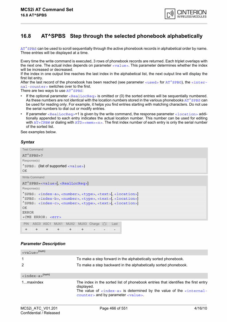
MC52i AT Command Set 16.8 AT^SPBS
MC52i_ATC_V01.201 Page 466 of 551 4/16/10Confidential / Released
16.8 AT^SPBS Step through the selected phonebook alphabetically
AT^SPBS can be used to scroll sequentially through the active phonebook records in alphabetical order by name.Three entries will be displayed at a time.
Every time the write command is executed, 3 rows of phonebook records are returned. Each triplet overlaps withthe next one. The actual index depends on parameter <value>. This parameter determines whether the indexwill be increased or decreased.If the index in one output line reaches the last index in the alphabetical list, the next output line will display thefirst list entry.After the last record of the phonebook has been reached (see parameter <used> for AT^SPBG), the <inter-nal-counter> switches over to the first.There are two ways to use AT^SPBS:
• If the optional parameter <RealLocReq> is omitted or (0) the sorted entries will be sequentially numbered.As these numbers are not identical with the location numbers stored in the various phonebooks AT^SPBS canbe used for reading only. For example, it helps you find entries starting with matching characters. Do not usethe serial numbers to dial out or modify entries.
• If parameter <RealLocReq>=1 is given by the write command, the response parameter <location> addi-tionally appended to each entry indicates the actual location number. This number can be used for editingwith AT+CPBW or dialing with ATD><mem><n>. The first index number of each entry is only the serial numberof the sorted list.
See examples below.
Syntax
Parameter Description
1 To make a step forward in the alphabetically sorted phonebook.
2 To make a step backward in the alphabetically sorted phonebook.
1...maxindex The index in the sorted list of phonebook entries that identifies the first entrydisplayed.The value of <index-a> is determined by the value of the <internal-counter> and by parameter <value>.
Test Command
AT^SPBS=?Response(s)
^SPBS: (list of supported <value>) OK
Write Command
AT^SPBS=<value>[, <RealLocReq>]Response(s)
^SPBS: <index-a>, <number>, <type>, <text>[, <location>]^SPBS: <index-b>, <number>, <type>, <text>[, <location>]^SPBS: <index-c>, <number>, <type>, <text>[, <location>]OKERROR+CME ERROR: <err>
PIN ASC0 ASC1 MUX1 MUX2 MUX3 Charge Last
+ + + + + + - - -
<value>(num)
<index-a>(num)
MC52i AT Command Set 16.8 AT^SPBS
MC52i_ATC_V01.201 Page 467 of 551 4/16/10Confidential / Released
After a write command has terminated successfully with "OK", the value fromparameter <index-a> is saved and retained as the new <internal-counter> value.Mind after the last record of phonebook, the first entry follows.
1...maxindex The index in the sorted list of phonebook entries that identifies the second entrydisplayed.<index-b>= (<index-a>+1).Mind after the last record of phonebook, the first entry follows.
1...maxindex The index in the sorted list of phonebook entries that identifies the third entrydisplayed.<index-c>= (<index-b>+1).Mind after the last record of phonebook, the first entry follows.
String type phone number in format specified by <type>.the number parameter may be an empty string.
Type of address octet, which defines the used type of number (ton) and the numbering plan identification (npi).Please consider that for types other than 129 or 145 dialing from phonebook with ATD><mem><n> is, dependingon the network, not always possible (refer to GSM 04.08 subclause 10.5.4.7 for details). See also <type> ofAT+CPBW. Possible values are:
145 Dialing string <number> includes international access code character '+'
161 National number. Network support of this type is optional.
209 Dialing string <number> has been saved as ASCII string and includes non-digit characters other than "*", "#" or "+". Note that phonebook entries savedwith this type cannot be dialed.
255 Dialing string <number> is a command to control a Supplementary Service,i.e. "*", "#" codes are contained. Network support of this type is optional.
129 Otherwise
Text assigned to the phone number.
Is a display of the "real" <location> of the entry required?
[0] Do not show an entry's "real" location number. Parameter <location> will notbe displayed
1 Show the "real" location number as parameter <location> at the end of theentry
The location within phonebook memory at which the corresponding entry is located.This location may be used for other phonebook commands (e.g. AT+CPBR, AT+CPBW, ATD><mem><n>).
<index-b>(num)
<index-c>(num)
<number>(str)
<type>(num)
<text>(str)(+CSCS)
<RealLocReq>(num)
<location>(num)
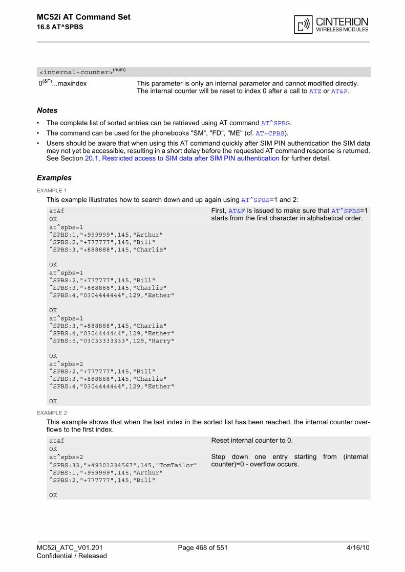
MC52i AT Command Set 16.8 AT^SPBS
MC52i_ATC_V01.201 Page 468 of 551 4/16/10Confidential / Released
0(&F)...maxindex This parameter is only an internal parameter and cannot modified directly.The internal counter will be reset to index 0 after a call to ATZ or AT&F.
Notes• The complete list of sorted entries can be retrieved using AT command AT^SPBG.
• The command can be used for the phonebooks "SM", "FD", "ME" (cf. AT+CPBS).
• Users should be aware that when using this AT command quickly after SIM PIN authentication the SIM datamay not yet be accessible, resulting in a short delay before the requested AT command response is returned.See Section 20.1, Restricted access to SIM data after SIM PIN authentication for further detail.
ExamplesEXAMPLE 1
This example illustrates how to search down and up again using AT^SPBS=1 and 2:
EXAMPLE 2
This example shows that when the last index in the sorted list has been reached, the internal counter over-flows to the first index.
<internal-counter>(num)
at&f First, AT&F is issued to make sure that AT^SPBS=1starts from the first character in alphabetical order.OK
at^spbs=1^SPBS:1,"+999999",145,"Arthur"^SPBS:2,"+777777",145,"Bill"^SPBS:3,"+888888",145,"Charlie"
OK at^spbs=1^SPBS:2,"+777777",145,"Bill"^SPBS:3,"+888888",145,"Charlie"^SPBS:4,"0304444444",129,"Esther"
OK at^spbs=1^SPBS:3,"+888888",145,"Charlie"^SPBS:4,"0304444444",129,"Esther"^SPBS:5,"03033333333",129,"Harry"
OK at^spbs=2^SPBS:2,"+777777",145,"Bill"^SPBS:3,"+888888",145,"Charlie"^SPBS:4,"0304444444",129,"Esther"
OK
at&f Reset internal counter to 0.OKat^spbs=2 Step down one entry starting from (internal
counter)=0 - overflow occurs.^SPBS:33,"+49301234567",145,"TomTailor"^SPBS:1,"+999999",145,"Arthur"^SPBS:2,"+777777",145,"Bill"
OK
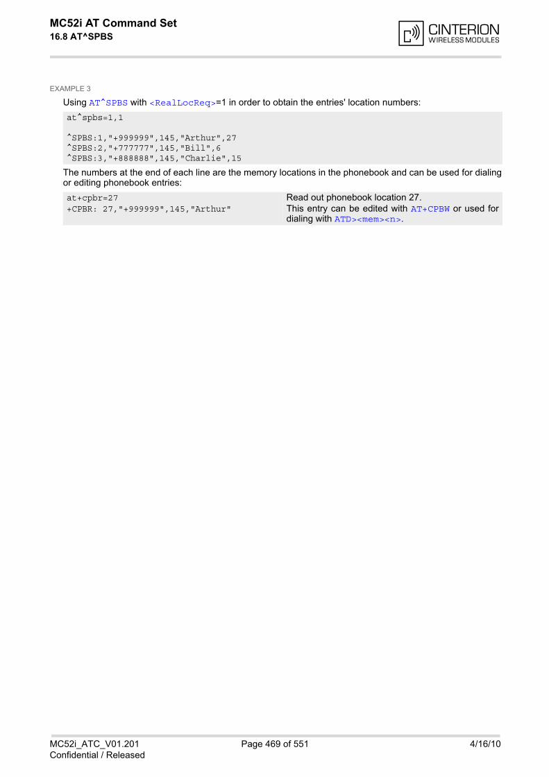
MC52i AT Command Set 16.8 AT^SPBS
MC52i_ATC_V01.201 Page 469 of 551 4/16/10Confidential / Released
EXAMPLE 3
Using AT^SPBS with <RealLocReq>=1 in order to obtain the entries' location numbers:
The numbers at the end of each line are the memory locations in the phonebook and can be used for dialingor editing phonebook entries:
at^spbs=1,1
^SPBS:1,"+999999",145,"Arthur",27^SPBS:2,"+777777",145,"Bill",6^SPBS:3,"+888888",145,"Charlie",15
at+cpbr=27 Read out phonebook location 27.+CPBR: 27,"+999999",145,"Arthur" This entry can be edited with AT+CPBW or used for
dialing with ATD><mem><n>.
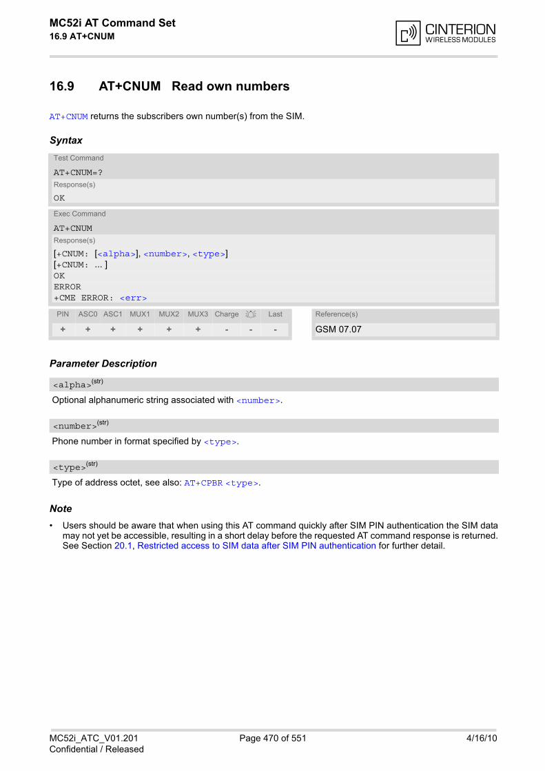
MC52i AT Command Set 16.9 AT+CNUM
MC52i_ATC_V01.201 Page 470 of 551 4/16/10Confidential / Released
16.9 AT+CNUM Read own numbers
AT+CNUM returns the subscribers own number(s) from the SIM.
Syntax
Parameter Description
Optional alphanumeric string associated with <number>.
Phone number in format specified by <type>.
Type of address octet, see also: AT+CPBR <type>.
Note• Users should be aware that when using this AT command quickly after SIM PIN authentication the SIM data
may not yet be accessible, resulting in a short delay before the requested AT command response is returned.See Section 20.1, Restricted access to SIM data after SIM PIN authentication for further detail.
Test Command
AT+CNUM=?Response(s)
OK
Exec Command
AT+CNUMResponse(s)
[+CNUM: [<alpha>], <number>, <type>][+CNUM: ... ]OKERROR+CME ERROR: <err>
PIN ASC0 ASC1 MUX1 MUX2 MUX3 Charge Last Reference(s)
+ + + + + + - - - GSM 07.07
<alpha>(str)
<number>(str)
<type>(str)
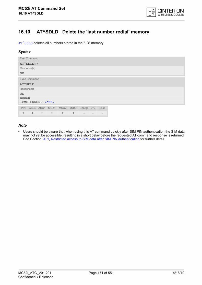
MC52i AT Command Set 16.10 AT^SDLD
MC52i_ATC_V01.201 Page 471 of 551 4/16/10Confidential / Released
16.10 AT^SDLD Delete the 'last number redial' memory
AT^SDLD deletes all numbers stored in the "LD" memory.
Syntax
Note• Users should be aware that when using this AT command quickly after SIM PIN authentication the SIM data
may not yet be accessible, resulting in a short delay before the requested AT command response is returned.See Section 20.1, Restricted access to SIM data after SIM PIN authentication for further detail.
Test Command
AT^SDLD=?Response(s)
OK
Exec Command
AT^SDLDResponse(s)
OKERROR+CME ERROR: <err>
PIN ASC0 ASC1 MUX1 MUX2 MUX3 Charge Last
+ + + + + + - - -
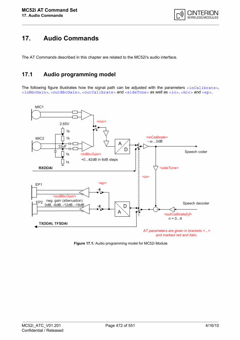
MC52i AT Command Set 17. Audio Commands
MC52i_ATC_V01.201 Page 472 of 551 4/16/10Confidential / Released
17. Audio Commands
The AT Commands described in this chapter are related to the MC52i's audio interface.
17.1 Audio programming model
The following figure illustrates how the signal path can be adjusted with the parameters <inCalibrate>,<inBbcGain>, <outBbcGain>, <outCalibrate> and <sideTone> as well as <io>, <mic> and <ep>.
Figure 17.1: Audio programming model for MC52i Module
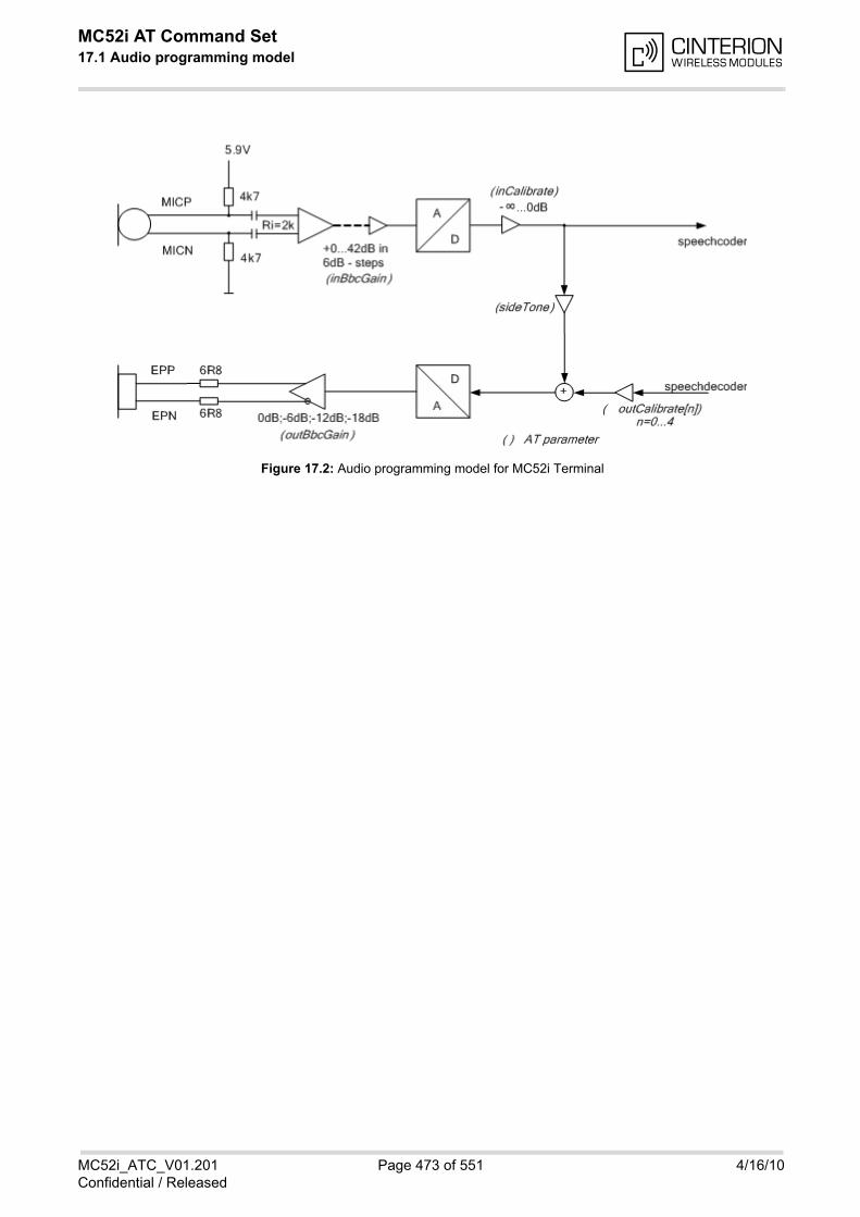
MC52i AT Command Set 17.1 Audio programming model
MC52i_ATC_V01.201 Page 473 of 551 4/16/10Confidential / Released
Figure 17.2: Audio programming model for MC52i Terminal
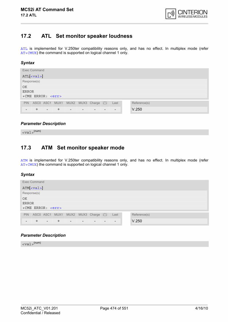
MC52i AT Command Set 17.2 ATL
MC52i_ATC_V01.201 Page 474 of 551 4/16/10Confidential / Released
17.2 ATL Set monitor speaker loudness
ATL is implemented for V.250ter compatibility reasons only, and has no effect. In multiplex mode (referAT+CMUX) the command is supported on logical channel 1 only.
Syntax
Parameter Description
17.3 ATM Set monitor speaker mode
ATM is implemented for V.250ter compatibility reasons only, and has no effect. In multiplex mode (referAT+CMUX) the command is supported on logical channel 1 only.
Syntax
Parameter Description
Exec Command
ATL[<val>]Response(s)
OKERROR+CME ERROR: <err>
PIN ASC0 ASC1 MUX1 MUX2 MUX3 Charge Last Reference(s)
- + - + - - - - - V.250
<val>(num)
Exec Command
ATM[<val>]Response(s)
OKERROR+CME ERROR: <err>
PIN ASC0 ASC1 MUX1 MUX2 MUX3 Charge Last Reference(s)
- + - + - - - - - V.250
<val>(num)
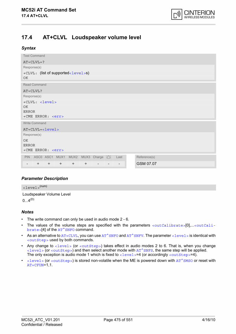
MC52i AT Command Set 17.4 AT+CLVL
MC52i_ATC_V01.201 Page 475 of 551 4/16/10Confidential / Released
17.4 AT+CLVL Loudspeaker volume level
Syntax
Parameter Description
Loudspeaker Volume Level
0...4(D)
Notes• The write command can only be used in audio mode 2 - 6.
• The values of the volume steps are specified with the parameters <outCalibrate>[0],...<outCali-brate>[4] of the AT^SNFO command.
• As an alternative to AT+CLVL, you can use AT^SNFO and AT^SNFV. The parameter <level> is identical with<outStep> used by both commands.
• Any change to <level> (or <outStep>) takes effect in audio modes 2 to 6. That is, when you change<level> (or <outStep>) and then select another mode with AT^SNFS, the same step will be applied.The only exception is audio mode 1 which is fixed to <level>=4 (or accordingly <outStep>=4).
• <level> (or <outStep>) is stored non-volatile when the ME is powered down with AT^SMSO or reset withAT+CFUN=1,1.
Test Command
AT+CLVL=?Response(s)
+CLVL: (list of supported<level>s)OK
Read Command
AT+CLVL?Response(s)
+CLVL: <level>OKERROR+CME ERROR: <err>
Write Command
AT+CLVL=<level>Response(s)
OKERROR+CME ERROR: <err>
PIN ASC0 ASC1 MUX1 MUX2 MUX3 Charge Last Reference(s)
- + + + + + - - - GSM 07.07
<level>(num)
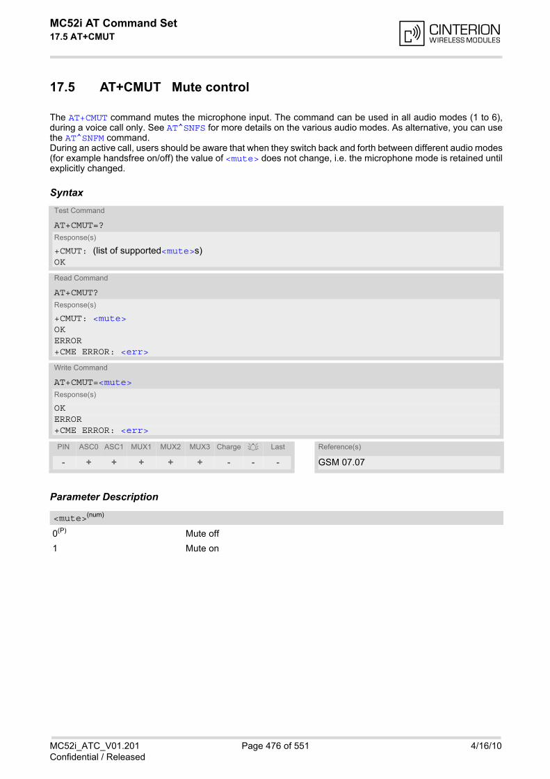
MC52i AT Command Set 17.5 AT+CMUT
MC52i_ATC_V01.201 Page 476 of 551 4/16/10Confidential / Released
17.5 AT+CMUT Mute control
The AT+CMUT command mutes the microphone input. The command can be used in all audio modes (1 to 6),during a voice call only. See AT^SNFS for more details on the various audio modes. As alternative, you can usethe AT^SNFM command.During an active call, users should be aware that when they switch back and forth between different audio modes(for example handsfree on/off) the value of <mute> does not change, i.e. the microphone mode is retained untilexplicitly changed.
Syntax
Parameter Description
0(P) Mute off
1 Mute on
Test Command
AT+CMUT=?Response(s)
+CMUT: (list of supported<mute>s)OK
Read Command
AT+CMUT?Response(s)
+CMUT: <mute>OKERROR+CME ERROR: <err>
Write Command
AT+CMUT=<mute>Response(s)
OKERROR+CME ERROR: <err>
PIN ASC0 ASC1 MUX1 MUX2 MUX3 Charge Last Reference(s)
- + + + + + - - - GSM 07.07
<mute>(num)

MC52i AT Command Set 17.6 AT+VTD
MC52i_ATC_V01.201 Page 477 of 551 4/16/10Confidential / Released
17.6 AT+VTD Tone duration
This command refers to an integer <duration> that defines the length of tones transmitted with the AT+VTScommand.
Syntax
Parameter Description
Duration of the DTMF signal in 1/10 seconds with tolerance. The minimum duration of DTMF signals is 300ms. DTMF tones below 300ms cannot be generated.
1(&F)(P)...255
Test Command
AT+VTD=?Response(s)
+VTD: (list of supported<duration>s)OK
Read Command
AT+VTD?Response(s)
<duration>OKERROR+CME ERROR: <err>
Write Command
AT+VTD=<duration>Response(s)
OKERROR+CME ERROR: <err>
PIN ASC0 ASC1 MUX1 MUX2 MUX3 Charge Last Reference(s)
- + + + + + - - - GSM 07.07
<duration>(num)

MC52i AT Command Set 17.7 AT+VTS
MC52i_ATC_V01.201 Page 478 of 551 4/16/10Confidential / Released
17.7 AT+VTS DTMF and tone generation
AT+VTS is intended to send ASCII characters or strings which cause the Mobile Switching Center (MSC) to trans-mit DTMF tones to a remote subscriber. The command can only be used during active voice calls and offers thefollowing variants:
• AT+VTS=<dtmfString> allows to send a sequence of DTMF tones with a duration defined with AT+VTD.
• AT+VTS=<dtmf>[,<duration>] allows to send a single DTMF tone. In this case, the duration can be ind-vidually determined during the call.
Syntax
Parameter Description
String of ASCII characters in the set 0-9,#,*,A, B, C, D. Maximal length of the string is 29. The string must beenclosed in quotation marks ("...").
ASCII character in the set 0...9,#,*, A, B, C, D.
Tone duration in 1/10 seconds with tolerance. If not specified current setting of AT+VTD is used. The minimum duration of DTMF signals is 300ms. DTMF tones below 300ms cannot be generated.
1...255
Test Command
AT+VTS=?Response(s)
+VTS: (list of supported<dtmf>s), (list of supported<duration>s)OK
Write Command
AT+VTS=<dtmfString>Response(s)
OKERROR+CME ERROR: <err>
Write Command
AT+VTS=<dtmf>[, <duration>]Response(s)
OKERROR+CME ERROR: <err>
PIN ASC0 ASC1 MUX1 MUX2 MUX3 Charge Last Reference(s)
- + + + + + - - - GSM 07.07
<dtmfString>(str)
<dtmf>(str)
<duration>(num)
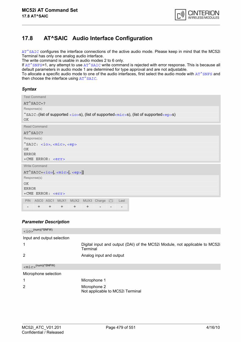
MC52i AT Command Set 17.8 AT^SAIC
MC52i_ATC_V01.201 Page 479 of 551 4/16/10Confidential / Released
17.8 AT^SAIC Audio Interface Configuration
AT^SAIC configures the interface connections of the active audio mode. Please keep in mind that the MC52iTerminal has only one analog audio interface. The write command is usable in audio modes 2 to 6 only. If AT^SNFS=1, any attempt to use AT^SAIC write command is rejected with error response. This is because alldefault parameters in audio mode 1 are determined for type approval and are not adjustable. To allocate a specific audio mode to one of the audio interfaces, first select the audio mode with AT^SNFS andthen choose the interface using AT^SAIC.
Syntax
Parameter Description
Input and output selection
1 Digital input and output (DAI) of the MC52i Module, not applicable to MC52iTerminal
2 Analog input and output
Microphone selection
1 Microphone 1
2 Microphone 2 Not applicable to MC52i Terminal
Test Command
AT^SAIC=?Response(s)
^SAIC:(list of supported <io>s), (list of supported<mic>s), (list of supported<ep>s)OK
Read Command
AT^SAIC?Response(s)
^SAIC: <io>, <mic>, <ep>OKERROR+CME ERROR: <err>
Write Command
AT^SAIC=<io>[, <mic>[, <ep>]]Response(s)
OKERROR+CME ERROR: <err>
PIN ASC0 ASC1 MUX1 MUX2 MUX3 Charge Last
- + + + + + - - -
<io>(num)(^SNFW)
<mic>(num)(^SNFW)
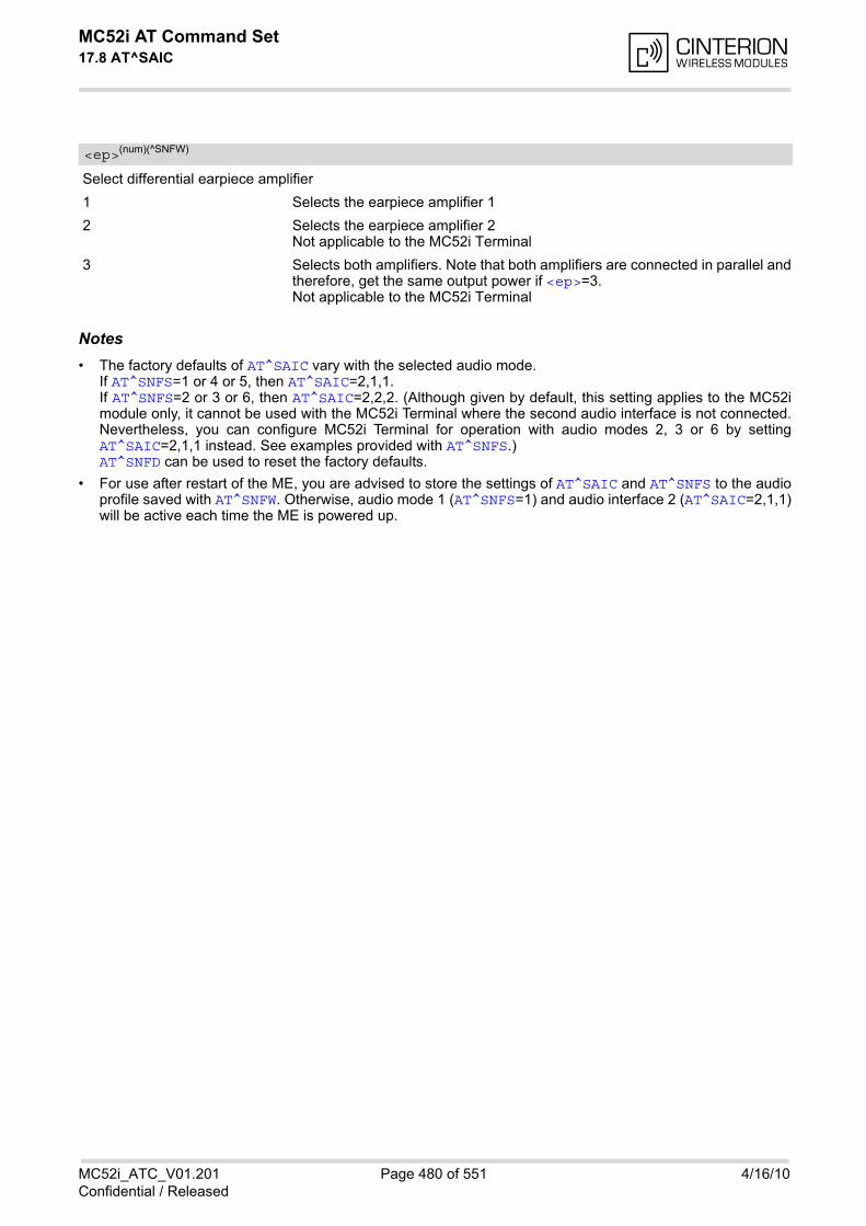
MC52i AT Command Set 17.8 AT^SAIC
MC52i_ATC_V01.201 Page 480 of 551 4/16/10Confidential / Released
Select differential earpiece amplifier
1 Selects the earpiece amplifier 1
2 Selects the earpiece amplifier 2 Not applicable to the MC52i Terminal
3 Selects both amplifiers. Note that both amplifiers are connected in parallel andtherefore, get the same output power if <ep>=3. Not applicable to the MC52i Terminal
Notes• The factory defaults of AT^SAIC vary with the selected audio mode.
If AT^SNFS=1 or 4 or 5, then AT^SAIC=2,1,1. If AT^SNFS=2 or 3 or 6, then AT^SAIC=2,2,2. (Although given by default, this setting applies to the MC52imodule only, it cannot be used with the MC52i Terminal where the second audio interface is not connected.Nevertheless, you can configure MC52i Terminal for operation with audio modes 2, 3 or 6 by settingAT^SAIC=2,1,1 instead. See examples provided with AT^SNFS.) AT^SNFD can be used to reset the factory defaults.
• For use after restart of the ME, you are advised to store the settings of AT^SAIC and AT^SNFS to the audioprofile saved with AT^SNFW. Otherwise, audio mode 1 (AT^SNFS=1) and audio interface 2 (AT^SAIC=2,1,1)will be active each time the ME is powered up.
<ep>(num)(^SNFW)

MC52i AT Command Set 17.9 AT^SNFA
MC52i_ATC_V01.201 Page 481 of 551 4/16/10Confidential / Released
17.9 AT^SNFA Set or query of microphone attenuation
AT^SNFA specifies the large-scale attenuation on the microphone path of the audio device currently selectedwith AT^SNFS. The write command is only available in audio modes 2 to 6.
Syntax
Parameter Description
Multiplication factor for input samples. Parameter <atten> is identical with <inCalibrate> of AT^SNFI.Formula used to calculate microphone attenuation (negative gain):Gain in dB = 20 * log(<atten>/32768)
0...32767(P)...65535
0 Microphone is muted. Please note that AT^SNFA cannot be used to mute the microphone. Therefore,any attempt to enter 0 will be rejected with error response. Value 0 is returnedonly by the read command AT^SNFA? after the microphone was muted withAT^SNFM=0 during an active call.
32767 No attenuation on the microphone pathValues greater than 32767 will be suppressed to 32767.
Notes• This command is provided for compatibility with former products (e.g. M20) and is a subset of AT^SNFI. The
parameter <inCalibrate> of AT^SNFI is identical with <atten> of AT^SNFA.
• To make the changes persistent use AT^SNFW.
Test Command
AT^SNFA=?Response(s)
^SNFA: (list of supported <atten>s) OK
Read Command
AT^SNFA?Response(s)
^SNFA: <atten>OKERROR+CME ERROR: <err>
Write Command
AT^SNFA=<atten>Response(s)
OKERROR+CME ERROR: <err>
PIN ASC0 ASC1 MUX1 MUX2 MUX3 Charge Last
- + + + + + - - -
<atten>(num)(^SNFW)

MC52i AT Command Set 17.9 AT^SNFA
MC52i_ATC_V01.201 Page 482 of 551 4/16/10Confidential / Released
Example
^SYSSTARTat^snfa=?^SNFA: (0-65535)OKat^snfa?^SNFA: 32767OKat^snfs=4OKat^snfa=1OKat^snfa?^SNFA: 1OKat^snfi?^SNFI: 5,1OKat^snfi=5,45OKat^snfa?^SNFA: 45OK
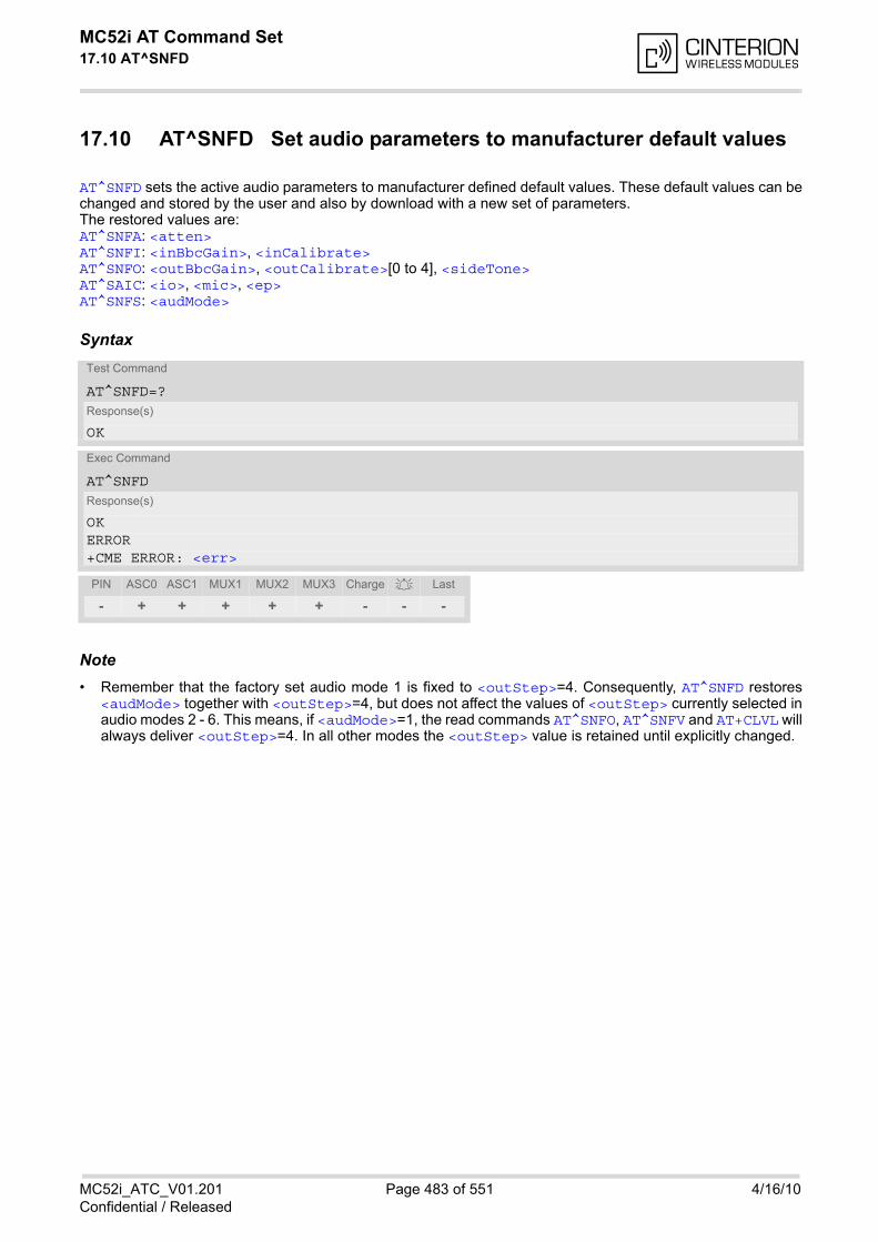
MC52i AT Command Set 17.10 AT^SNFD
MC52i_ATC_V01.201 Page 483 of 551 4/16/10Confidential / Released
17.10 AT^SNFD Set audio parameters to manufacturer default values
AT^SNFD sets the active audio parameters to manufacturer defined default values. These default values can bechanged and stored by the user and also by download with a new set of parameters.The restored values are:AT^SNFA: <atten>AT^SNFI: <inBbcGain>, <inCalibrate>AT^SNFO: <outBbcGain>, <outCalibrate>[0 to 4], <sideTone>AT^SAIC: <io>, <mic>, <ep>AT^SNFS: <audMode>
Syntax
Note• Remember that the factory set audio mode 1 is fixed to <outStep>=4. Consequently, AT^SNFD restores
<audMode> together with <outStep>=4, but does not affect the values of <outStep> currently selected inaudio modes 2 - 6. This means, if <audMode>=1, the read commands AT^SNFO, AT^SNFV and AT+CLVL willalways deliver <outStep>=4. In all other modes the <outStep> value is retained until explicitly changed.
Test Command
AT^SNFD=?Response(s)
OK
Exec Command
AT^SNFDResponse(s)
OKERROR+CME ERROR: <err>
PIN ASC0 ASC1 MUX1 MUX2 MUX3 Charge Last
- + + + + + - - -

MC52i AT Command Set 17.11 AT^SNFI
MC52i_ATC_V01.201 Page 484 of 551 4/16/10Confidential / Released
17.11 AT^SNFI Set microphone path parameters
AT^SNFI controls the microphone path amplification. Read and write options of this command refer to the activeaudio mode. The write command works only in audio modes 2 to 6.
Syntax
Parameter Description
ADC gain adjustable in eight 6 dB steps from 0 dB to 42 dB (0=0dB, 7=42dB, 8 steps of 6 dB).
0...7
Multiplication factor for input samples. Formula to calculate the negative gain (attenuation) of the input signal:Gain in dB = 20 * log (inCalibrate / 32768)
0...32767
Notes• The range of <inCalibrate> is up to 65535 but will be suppressed to 32767. Values above <inCali-
brate>= 65535 will cause a failure.
• The parameter <inCalibrate> of AT^SNFI is identical with <atten> of AT^SNFA.
• For use after restart, changed values can be stored with AT^SNFW.
• Attention! When you adjust audio parameters avoid exceeding the maximum allowed level. Bear in mind thatexposure to excessive levels of noise can cause physical damage to users!
Test Command
AT^SNFI=?Response(s)
^SNFI: (list of supported <inBbcGain>s) , (list of supported <inCalibrate>s) OK
Read Command
AT^SNFI?Response(s)
^SNFI: <inBbcGain>, <inCalibrate>OKERROR+CME ERROR: <err>
Write Command
AT^SNFI=<inBbcGain>, <inCalibrate>Response(s)
OKERROR+CME ERROR: <err>
PIN ASC0 ASC1 MUX1 MUX2 MUX3 Charge Last
- + + + + + - - -
<inBbcGain>(num)(^SNFW)
<inCalibrate>(num)(^SNFW)

MC52i AT Command Set 17.12 AT^SNFM
MC52i_ATC_V01.201 Page 485 of 551 4/16/10Confidential / Released
17.12 AT^SNFM Set microphone audio path and power supply
The AT^SNFM read command returns the microphone mute and supply voltage status.The AT^SNFM write command can be used to switch the microphone's audio path (muted / not muted) or to con-trol the power supply of the MICP2 line (microphone input of the second analog audio interface). Please keep in mind that the MC52i Terminal has no programmable microphone power supply, therefore onlythe mute switch applies. The microphone can be muted or activated by changing <MicSwitch> in all audio modes (1 to 6), during a voicecall only. As an alternative, you can use the AT+CMUT command to mute the microphone.
Syntax
Parameter Description
Microphone mute control parameter. Evaluated only during voice calls and if <MicVccCtl> is omitted, e.g. AT^SNFM=1. Command does not depend on audio mode.
0 Mutes the microphone.
1(P) Activates the microphone.
Microphone supply voltage control parameter. Parameter is not applicable to the MC52i Terminal. Setting applies to microphone input 2 only. CME error is given if <MicSwitch> is not omitted. Enter for example AT^SNFM=,1 or AT^SNFM=,2.
0 Supply voltage is always switched off.
1 Supply voltage is always switched on.
2(P) Supply voltage state during voice calls is controlled by the ME. The actualvalue is determined by the parameter data set of the selected audio mode.
Test Command
AT^SNFM=?Response(s)
^SNFM: (list of supported <MicSwitch>s) , (list of supported <MicVccCtl>s) OK
Read Command
AT^SNFM?Response(s)
^SNFM: <MicSwitch>, <MicVccState>OKERROR+CME ERROR: <err>
Write Command
AT^SNFM=[<MicSwitch>][, <MicVccCtl>]Response(s)
OKERROR+CME ERROR: <err>
PIN ASC0 ASC1 MUX1 MUX2 MUX3 Charge Last
- + + + + + - - -
<MicSwitch>(num)
<MicVccCtl>(num)
MC52i AT Command Set 17.12 AT^SNFM
MC52i_ATC_V01.201 Page 486 of 551 4/16/10Confidential / Released
Microphone supply voltage control status.
0 Supply voltage was set to a constant value.
2 Supply voltage state is controlled by the ME and depends on the parameterdata set of the selected audio mode.
Notes• The programmable power supply of the MICP2 line gives you greater flexibility in connecting audio accesso-
ries or using MICP2 for a variety of functions other than audio. A detailed description of the extended usageof MICP2 can be found in [8].
• During an active call, users should be aware that when they switch back and forth between different audiomodes (for example handsfree on/off) the value of <MicSwitch> does not change, i.e. the microphone modeis retained until explicitly changed.
<MicVccState>(num)
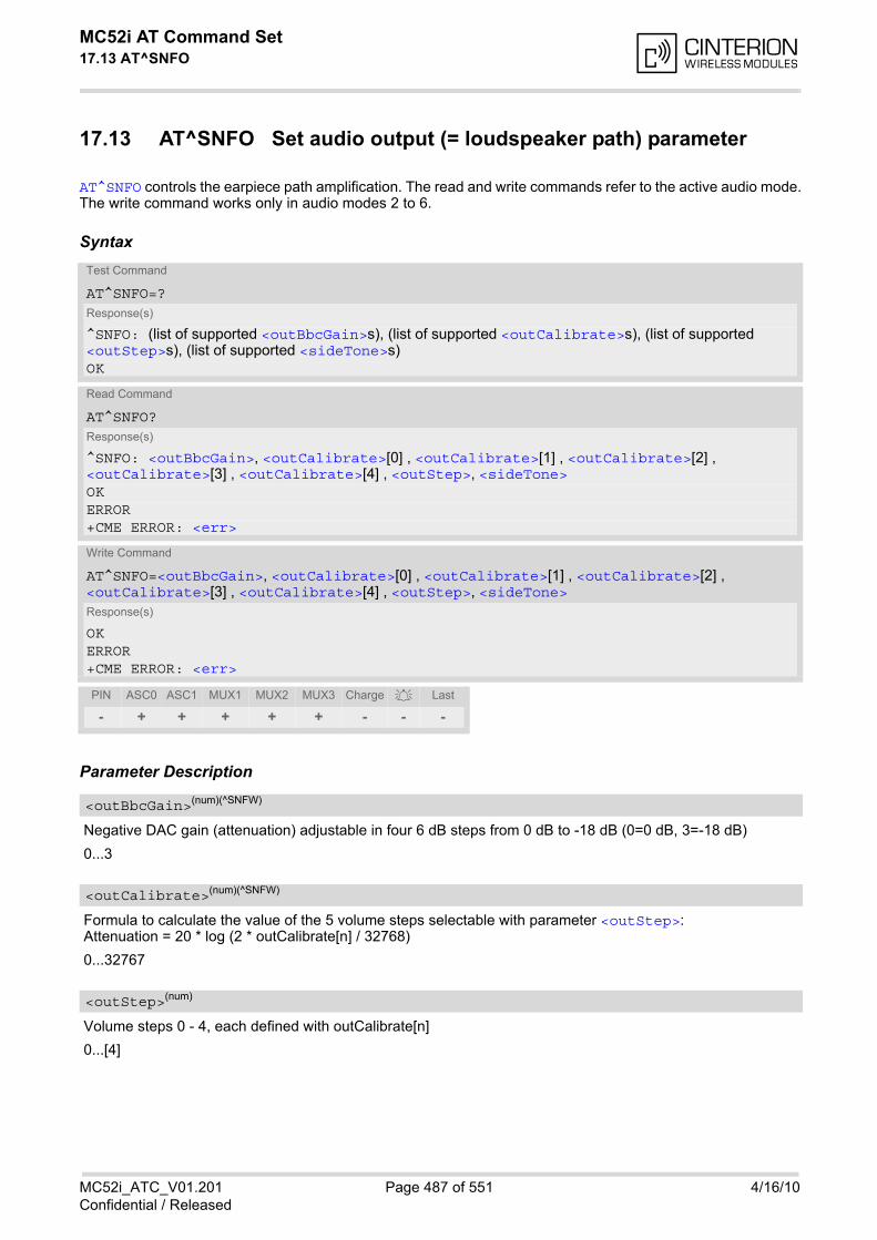
MC52i AT Command Set 17.13 AT^SNFO
MC52i_ATC_V01.201 Page 487 of 551 4/16/10Confidential / Released
17.13 AT^SNFO Set audio output (= loudspeaker path) parameter
AT^SNFO controls the earpiece path amplification. The read and write commands refer to the active audio mode.The write command works only in audio modes 2 to 6.
Syntax
Parameter Description
Negative DAC gain (attenuation) adjustable in four 6 dB steps from 0 dB to -18 dB (0=0 dB, 3=-18 dB)
0...3
Formula to calculate the value of the 5 volume steps selectable with parameter <outStep>:Attenuation = 20 * log (2 * outCalibrate[n] / 32768)
0...32767
Volume steps 0 - 4, each defined with outCalibrate[n]
0...[4]
Test Command
AT^SNFO=?Response(s)
^SNFO: (list of supported <outBbcGain>s), (list of supported <outCalibrate>s), (list of supported <outStep>s), (list of supported <sideTone>s)OK
Read Command
AT^SNFO?Response(s)
^SNFO: <outBbcGain>, <outCalibrate>[0] , <outCalibrate>[1] , <outCalibrate>[2] , <outCalibrate>[3] , <outCalibrate>[4] , <outStep>, <sideTone>OKERROR+CME ERROR: <err>
Write Command
AT^SNFO=<outBbcGain>, <outCalibrate>[0] , <outCalibrate>[1] , <outCalibrate>[2] , <outCalibrate>[3] , <outCalibrate>[4] , <outStep>, <sideTone>Response(s)
OKERROR+CME ERROR: <err>
PIN ASC0 ASC1 MUX1 MUX2 MUX3 Charge Last
- + + + + + - - -
<outBbcGain>(num)(^SNFW)
<outCalibrate>(num)(^SNFW)
<outStep>(num)
MC52i AT Command Set 17.13 AT^SNFO
MC52i_ATC_V01.201 Page 488 of 551 4/16/10Confidential / Released
Multiplication factor for the sidetone gain.Formula to calculate how much of the original microphone signal is added to the earpiece signal:Sidetone gain in dB = 20 * log (sideTone / 32768).
0...32767
Notes• <outCalibrate> specifies the amount of volume of each <outStep>. The range of each <outCali-
brate> is up to 65535, but will be suppressed to 32767. A value above <outCalibrate>= 65535 will causean error.
• The range of <sideTone> is up to 65535, but will be suppressed to 32767. A value above <sideTone>=65535 will cause an error.
• Any change to <outStep> takes effect in audio modes 2 to 6. That is, when you change <outStep> andthen select another mode with AT^SNFS, the same step will be applied. Nevertheless, the sound quality andthe amount of volume are not necessarily the same, since all remaining audio parameters can use differentvalues in either mode.
• Audio mode 1 is fixed to <outStep>=4. In this mode, any attempt to change <outStep> or other parametersreturns an error.
• The value of <outStep> is stored non-volatile when the ME is powered down with AT^SMSO or reset withAT+CFUN=x,1. Any other parameters changed with AT^SNFO need to be saved with AT^SNFW for use afterrestart. See also AT^SNFD for details on restoring factory defaults.
• The values of <outStep> can also be changed with AT^SNFV and AT+CLVL.
• CAUTION! When you adjust audio parameters avoid exceeding the maximum allowed level. Bear in mind thatexposure to excessive levels of noise can cause physical damage to users!
<sideTone>(num)(^SNFW)
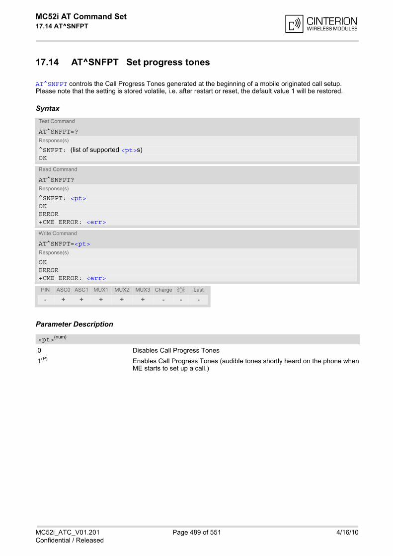
MC52i AT Command Set 17.14 AT^SNFPT
MC52i_ATC_V01.201 Page 489 of 551 4/16/10Confidential / Released
17.14 AT^SNFPT Set progress tones
AT^SNFPT controls the Call Progress Tones generated at the beginning of a mobile originated call setup. Please note that the setting is stored volatile, i.e. after restart or reset, the default value 1 will be restored.
Syntax
Parameter Description
0 Disables Call Progress Tones
1(P) Enables Call Progress Tones (audible tones shortly heard on the phone whenME starts to set up a call.)
Test Command
AT^SNFPT=?Response(s)
^SNFPT: (list of supported <pt>s) OK
Read Command
AT^SNFPT?Response(s)
^SNFPT: <pt>OKERROR+CME ERROR: <err>
Write Command
AT^SNFPT=<pt>Response(s)
OKERROR+CME ERROR: <err>
PIN ASC0 ASC1 MUX1 MUX2 MUX3 Charge Last
- + + + + + - - -
<pt>(num)
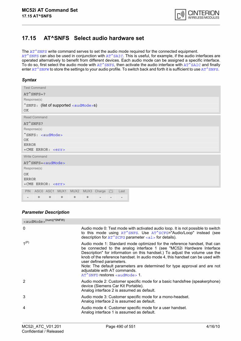
MC52i AT Command Set 17.15 AT^SNFS
MC52i_ATC_V01.201 Page 490 of 551 4/16/10Confidential / Released
17.15 AT^SNFS Select audio hardware set
The AT^SNFS write command serves to set the audio mode required for the connected equipment. AT^SNFS can also be used in conjunction with AT^SAIC. This is useful, for example, if the audio interfaces areoperated alternatively to benefit from different devices. Each audio mode can be assigned a specific interface.To do so, first select the audio mode with AT^SNFS, then activate the audio interface with AT^SAIC and finallyenter AT^SNFW to store the settings to your audio profile. To switch back and forth it is sufficient to use AT^SNFS.
Syntax
Parameter Description
0 Audio mode 0: Test mode with activated audio loop. It is not possible to switchto this mode using AT^SNFS. Use AT^SCFG="Audio/Loop" instead (seedescription for AT^SCFG parameter <al> for details).
1(P) Audio mode 1: Standard mode optimized for the reference handset, that canbe connected to the analog interface 1 (see "MC52i Hardware InterfaceDescription" for information on this handset.) To adjust the volume use theknob of the reference handset. In audio mode 4, this handset can be used withuser defined parameters. Note: The default parameters are determined for type approval and are notadjustable with AT commands. AT^SNFD restores <audMode> 1.
2 Audio mode 2: Customer specific mode for a basic handsfree (speakerphone)device (Siemens Car Kit Portable).Analog interface 2 is assumed as default.
3 Audio mode 3: Customer specific mode for a mono-headset.Analog interface 2 is assumed as default.
4 Audio mode 4: Customer specific mode for a user handset.Analog interface 1 is assumed as default.
Test Command
AT^SNFS=?Response(s)
^SNFS: (list of supported <audMode>s) OK
Read Command
AT^SNFS?Response(s)
^SNFS: <audMode>OKERROR+CME ERROR: <err>
Write Command
AT^SNFS=<audMode>Response(s)
OKERROR+CME ERROR: <err>
PIN ASC0 ASC1 MUX1 MUX2 MUX3 Charge Last
- + + + + + - - -
<audMode>(num)(^SNFW)
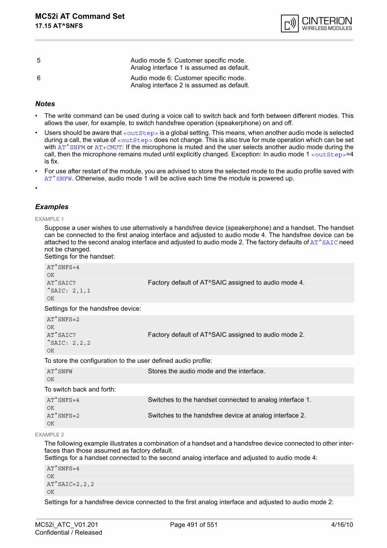
MC52i AT Command Set 17.15 AT^SNFS
MC52i_ATC_V01.201 Page 491 of 551 4/16/10Confidential / Released
5 Audio mode 5: Customer specific mode. Analog interface 1 is assumed as default.
6 Audio mode 6: Customer specific mode.Analog interface 2 is assumed as default.
Notes• The write command can be used during a voice call to switch back and forth between different modes. This
allows the user, for example, to switch handsfree operation (speakerphone) on and off.
• Users should be aware that <outStep> is a global setting. This means, when another audio mode is selectedduring a call, the value of <outStep> does not change. This is also true for mute operation which can be setwith AT^SNFM or AT+CMUT: If the microphone is muted and the user selects another audio mode during thecall, then the microphone remains muted until explicitly changed. Exception: In audio mode 1 <outStep>=4is fix.
• For use after restart of the module, you are advised to store the selected mode to the audio profile saved withAT^SNFW. Otherwise, audio mode 1 will be active each time the module is powered up.
•
ExamplesEXAMPLE 1
Suppose a user wishes to use alternatively a handsfree device (speakerphone) and a handset. The handsetcan be connected to the first analog interface and adjusted to audio mode 4. The handsfree device can beattached to the second analog interface and adjusted to audio mode 2. The factory defaults of AT^SAIC neednot be changed.Settings for the handset:
Settings for the handsfree device:
To store the configuration to the user defined audio profile:
To switch back and forth:
EXAMPLE 2
The following example illustrates a combination of a handset and a handsfree device connected to other inter-faces than those assumed as factory default.Settings for a handset connected to the second analog interface and adjusted to audio mode 4:
Settings for a handsfree device connected to the first analog interface and adjusted to audio mode 2:
AT^SNFS=4OKAT^SAIC? Factory default of AT^SAIC assigned to audio mode 4.^SAIC: 2,1,1OK
AT^SNFS=2OKAT^SAIC? Factory default of AT^SAIC assigned to audio mode 2.^SAIC: 2,2,2OK
AT^SNFW Stores the audio mode and the interface.OK
AT^SNFS=4 Switches to the handset connected to analog interface 1.OKAT^SNFS=2 Switches to the handsfree device at analog interface 2.OK
AT^SNFS=4OKAT^SAIC=2,2,2OK

MC52i AT Command Set 17.15 AT^SNFS
MC52i_ATC_V01.201 Page 492 of 551 4/16/10Confidential / Released
To store the configuration to the user defined audio profile:
To switch back and forth:
AT^SNFS=2OKAT^SAIC=2,1,1OK
AT^SNFW Stores the audio mode and the interface.OK
AT^SNFS=4 Switches to the handset connected to analog interface 1.OKAT^SNFS=2 Switches to the handsfree device at analog interface 2.OK
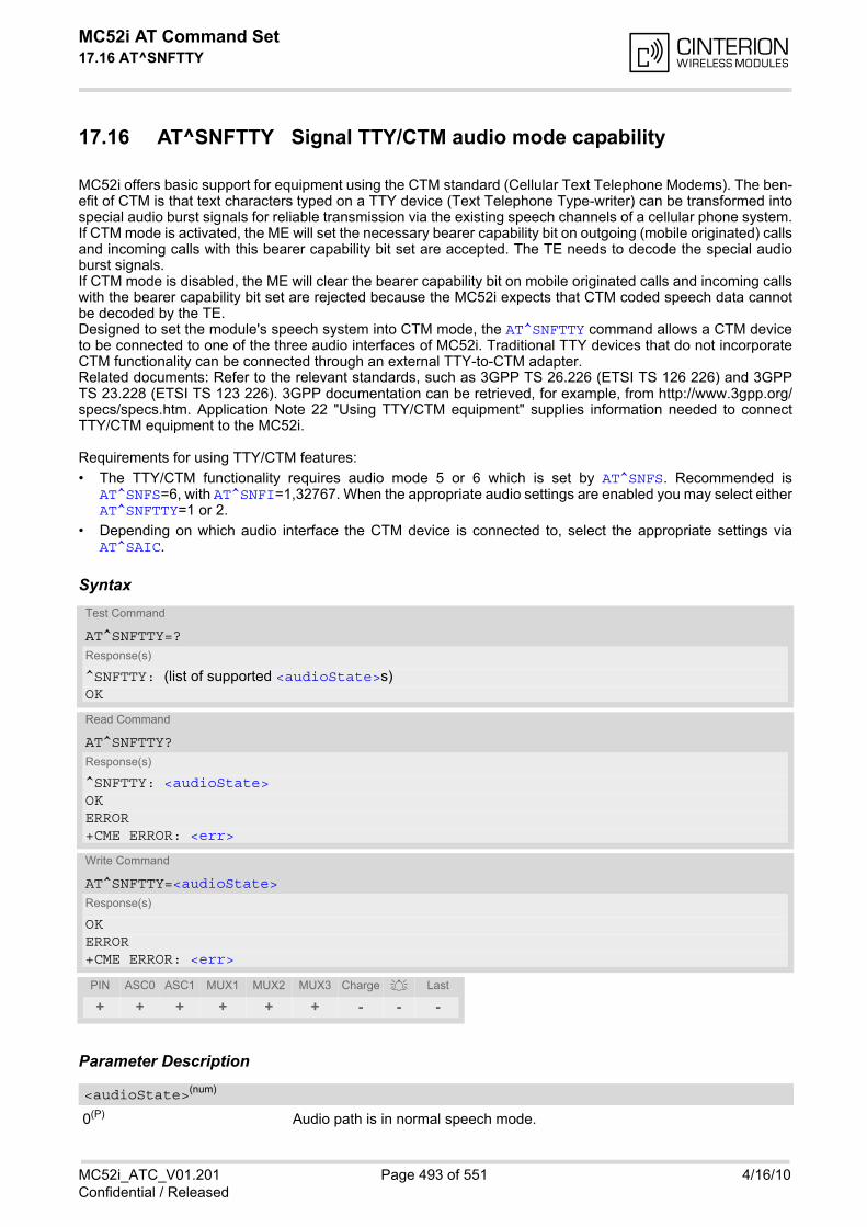
MC52i AT Command Set 17.16 AT^SNFTTY
MC52i_ATC_V01.201 Page 493 of 551 4/16/10Confidential / Released
17.16 AT^SNFTTY Signal TTY/CTM audio mode capability
MC52i offers basic support for equipment using the CTM standard (Cellular Text Telephone Modems). The ben-efit of CTM is that text characters typed on a TTY device (Text Telephone Type-writer) can be transformed intospecial audio burst signals for reliable transmission via the existing speech channels of a cellular phone system.If CTM mode is activated, the ME will set the necessary bearer capability bit on outgoing (mobile originated) callsand incoming calls with this bearer capability bit set are accepted. The TE needs to decode the special audioburst signals. If CTM mode is disabled, the ME will clear the bearer capability bit on mobile originated calls and incoming callswith the bearer capability bit set are rejected because the MC52i expects that CTM coded speech data cannotbe decoded by the TE. Designed to set the module's speech system into CTM mode, the AT^SNFTTY command allows a CTM deviceto be connected to one of the three audio interfaces of MC52i. Traditional TTY devices that do not incorporateCTM functionality can be connected through an external TTY-to-CTM adapter. Related documents: Refer to the relevant standards, such as 3GPP TS 26.226 (ETSI TS 126 226) and 3GPPTS 23.228 (ETSI TS 123 226). 3GPP documentation can be retrieved, for example, from http://www.3gpp.org/specs/specs.htm. Application Note 22 "Using TTY/CTM equipment" supplies information needed to connectTTY/CTM equipment to the MC52i.
Requirements for using TTY/CTM features:
• The TTY/CTM functionality requires audio mode 5 or 6 which is set by AT^SNFS. Recommended isAT^SNFS=6, with AT^SNFI=1,32767. When the appropriate audio settings are enabled you may select eitherAT^SNFTTY=1 or 2.
• Depending on which audio interface the CTM device is connected to, select the appropriate settings viaAT^SAIC.
Syntax
Parameter Description
0(P) Audio path is in normal speech mode.
Test Command
AT^SNFTTY=?Response(s)
^SNFTTY: (list of supported <audioState>s) OK
Read Command
AT^SNFTTY?Response(s)
^SNFTTY: <audioState>OKERROR+CME ERROR: <err>
Write Command
AT^SNFTTY=<audioState>Response(s)
OKERROR+CME ERROR: <err>
PIN ASC0 ASC1 MUX1 MUX2 MUX3 Charge Last
+ + + + + + - - -
<audioState>(num)
MC52i AT Command Set 17.16 AT^SNFTTY
MC52i_ATC_V01.201 Page 494 of 551 4/16/10Confidential / Released
1 Audio path is in TTY/CTM mode (external CTM modem).
2 Audio path is in TTY/CTM mode (internal CTM modem).
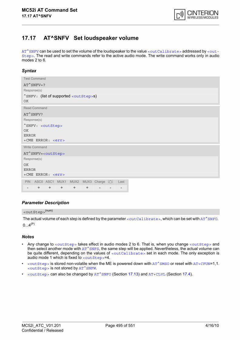
MC52i AT Command Set 17.17 AT^SNFV
MC52i_ATC_V01.201 Page 495 of 551 4/16/10Confidential / Released
17.17 AT^SNFV Set loudspeaker volume
AT^SNFV can be used to set the volume of the loudspeaker to the value <outCalibrate> addressed by <out-Step>. The read and write commands refer to the active audio mode. The write command works only in audiomodes 2 to 6.
Syntax
Parameter Description
The actual volume of each step is defined by the parameter <outCalibrate>, which can be set with AT^SNFO.
0...4(P)
Notes• Any change to <outStep> takes effect in audio modes 2 to 6. That is, when you change <outStep> and
then select another mode with AT^SNFS, the same step will be applied. Nevertheless, the actual volume canbe quite different, depending on the values of <outCalibrate> set in each mode. The only exception isaudio mode 1 which is fixed to <outStep>=4.
• <outStep> is stored non-volatile when the ME is powered down with AT^SMSO or reset with AT+CFUN=1,1.<outStep> is not stored by AT^SNFW.
• <outStep> can also be changed by AT^SNFO (Section 17.13) and AT+CLVL (Section 17.4).
Test Command
AT^SNFV=?Response(s)
^SNFV: (list of supported <outStep>s) OK
Read Command
AT^SNFV?Response(s)
^SNFV: <outStep>OKERROR+CME ERROR: <err>
Write Command
AT^SNFV=<outStep>Response(s)
OKERROR+CME ERROR: <err>
PIN ASC0 ASC1 MUX1 MUX2 MUX3 Charge Last
- + + + + + - - -
<outStep>(num)
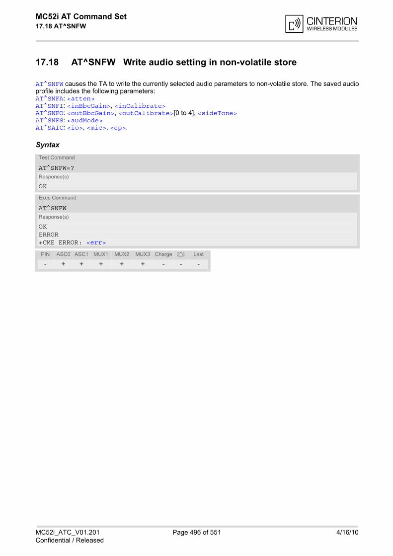
MC52i AT Command Set 17.18 AT^SNFW
MC52i_ATC_V01.201 Page 496 of 551 4/16/10Confidential / Released
17.18 AT^SNFW Write audio setting in non-volatile store
AT^SNFW causes the TA to write the currently selected audio parameters to non-volatile store. The saved audioprofile includes the following parameters: AT^SNFA: <atten> AT^SNFI: <inBbcGain>, <inCalibrate> AT^SNFO: <outBbcGain>, <outCalibrate>[0 to 4], <sideTone> AT^SNFS: <audMode> AT^SAIC: <io>, <mic>, <ep>.
SyntaxTest Command
AT^SNFW=?Response(s)
OK
Exec Command
AT^SNFWResponse(s)
OKERROR+CME ERROR: <err>
PIN ASC0 ASC1 MUX1 MUX2 MUX3 Charge Last
- + + + + + - - -
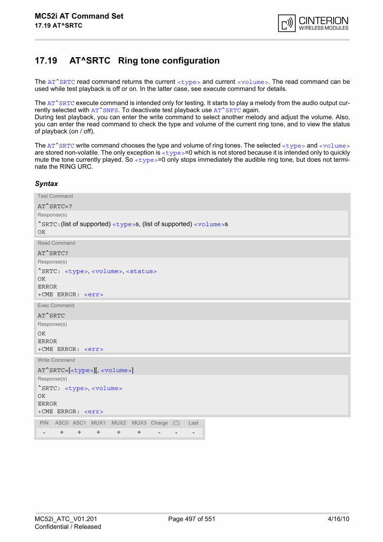
MC52i AT Command Set 17.19 AT^SRTC
MC52i_ATC_V01.201 Page 497 of 551 4/16/10Confidential / Released
17.19 AT^SRTC Ring tone configuration
The AT^SRTC read command returns the current <type> and current <volume>. The read command can beused while test playback is off or on. In the latter case, see execute command for details.
The AT^SRTC execute command is intended only for testing. It starts to play a melody from the audio output cur-rently selected with AT^SNFS. To deactivate test playback use AT^SRTC again.During test playback, you can enter the write command to select another melody and adjust the volume. Also,you can enter the read command to check the type and volume of the current ring tone, and to view the statusof playback (on / off).
The AT^SRTC write command chooses the type and volume of ring tones. The selected <type> and <volume>are stored non-volatile. The only exception is <type>=0 which is not stored because it is intended only to quicklymute the tone currently played. So <type>=0 only stops immediately the audible ring tone, but does not termi-nate the RING URC.
SyntaxTest Command
AT^SRTC=?Response(s)
^SRTC:(list of supported) <type>s, (list of supported) <volume>sOK
Read Command
AT^SRTC?Response(s)
^SRTC: <type>, <volume>, <status>OKERROR+CME ERROR: <err>
Exec Command
AT^SRTCResponse(s)
OKERROR+CME ERROR: <err>
Write Command
AT^SRTC=[<type>][, <volume>]Response(s)
^SRTC: <type>, <volume>OKERROR+CME ERROR: <err>
PIN ASC0 ASC1 MUX1 MUX2 MUX3 Charge Last
- + + + + + - - -
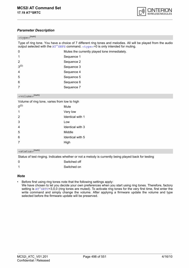
MC52i AT Command Set 17.19 AT^SRTC
MC52i_ATC_V01.201 Page 498 of 551 4/16/10Confidential / Released
Parameter Description
Type of ring tone. You have a choice of 7 different ring tones and melodies. All will be played from the audiooutput selected with the AT^SNFS command. <type>=0 is only intended for muting.
0 Mutes the currently played tone immediately.
1 Sequence 1
2 Sequence 2
3(D) Sequence 3
4 Sequence 4
5 Sequence 5
6 Sequence 6
7 Sequence 7
Volume of ring tone, varies from low to high
0(D) Mute
1 Very low
2 Identical with 1
3 Low
4 Identical with 3
5 Middle
6 Identical with 5
7 High
Status of test ringing. Indicates whether or not a melody is currently being played back for testing
0 Switched off
1 Switched on
Note• Before first using ring tones note that the following settings apply:
We have chosen to let you decide your own preferences when you start using ring tones. Therefore, factorysetting is AT^SRTC=3,0,0 (ring tones are muted). To activate ring tones for the very first time, first enter thewrite command and simply change the volume. After applying a firmware update the volume and typeselected before the firmware update will be preserved.
<type>(num)
<volume>(num)
<status>(num)

MC52i AT Command Set 18. Hardware related Commands
MC52i_ATC_V01.201 Page 499 of 551 4/16/10Confidential / Released
18. Hardware related Commands
All AT commands described in this chapter are related to the hardware interface of the MC52i. Further informa-tion regarding this interface is available in the "MC52i Hardware Interface Description" [2].
18.1 AT+CCLK Real Time Clock
Syntax
Parameter Description
Format is "yy/mm/dd,hh:mm:ss", where the characters indicate the two last digits of the year, followed by month,day, hour, minutes, seconds; for example 6th of July 2005, 22:10:00 hours equals to "05/07/06,22:10:00"Factory default is "03/01/01,00:00:00"
Notes• <time> is retained if the device enters the Power Down mode via AT^SMSO.
• <time> will be reset to its factory default if power is totally disconnected. In this case, the clock starts with<time>= "03/01/01,00:00:00" upon next power-up.
• Each time MC52i is restarted it takes 2s to re-initialize the RTC and to update the current time. Therefore, itis recommended to wait 2s before using the commands AT+CCLK and AT+CALA (for example 2s after^SYSSTART has been output).
Test Command
AT+CCLK=?Response(s)
OK
Read Command
AT+CCLK?Response(s)
+CCLK: <time>OK
Write Command
AT+CCLK=<time>Response(s)
OKERROR+CME ERROR: <err>
PIN ASC0 ASC1 MUX1 MUX2 MUX3 Charge Last Reference(s)
- + + + + + + + - GSM 07.07
<time>(str)
MC52i AT Command Set 18.2 AT+CALA
MC52i_ATC_V01.201 Page 500 of 551 4/16/10Confidential / Released
18.2 AT+CALA Set alarm time
The AT+CALA write command can be used to set an alarm time in the ME When the alarm time is reached andthe alarm is executed the ME returns an Unsolicited Result Code (URC) and the alarm time is reset to "00/01/01,00:00:00".The alarm can adopt two functions, depending on whether or not you switch the ME off after setting the alarm:
• Reminder message: You can use the alarm function to generate reminder messages. For this purpose, setthe alarm as described below and do not switch off or power down the ME. When executed the messagecomes as an Unsolicited Result Code which reads "+CALA".
• Alarm mode (only applicable to MC52i Module, not permitted for MC52i Terminal): You can use the alarmfunction to restart the ME when powered down. For this purpose, set the alarm as described below. Thenpower down the ME by entering the AT^SMSO command. When the alarm time is reached, the ME will wakeup to Alarm mode. To prevent the ME from unintentionally logging into the GSM network, Alarm mode pro-vides restricted operation. Upon wake-up, the ME indicates an Unsolicited Result Code which reads:"+CALA". A limited number of AT commands is available during Alarm mode, for details see Section 20.4,Availability of AT Commands Depending on Operating Mode of ME. The ME remains dereg-istered from the GSM network.If you want the ME to return to full operation (normal operating mode) it is necessary to restart the ME bydriving the ignition line (IGT pin of application interface) to ground. If your ME is battery powered note that the battery can be charged while the ME stays in Alarm mode. Fordetails please refer to [2].
The AT+CALA test command returns the supported array index values <n>, the supported alarm types <type>and the maximum length of the text <tlength> to be output.The AT+CALA read command returns the current alarm settings in the ME.
SyntaxTest Command
AT+CALA=?Response(s)
+CALA: (list of supported<n>s), (list of supported<type>s), (list of supported<tlength>s)OKERROR+CME ERROR: <err>
Read Command
AT+CALA?Response(s)
+CALA: <time>[, <n>[, <type>[, <text>]]]OKERROR+CME ERROR: <err>
Write Command
AT+CALA=<time>[, <n>[, <type>[, <text>]]]Response(s)
OKERROR+CME ERROR: <err>
PIN ASC0 ASC1 MUX1 MUX2 MUX3 Charge Last Reference(s)
- + + + + + + + - GSM 07.07
MC52i AT Command Set 18.2 AT+CALA
MC52i_ATC_V01.201 Page 501 of 551 4/16/10Confidential / Released
Unsolicited Result Codes
URC 1
+CALA: [<text>]
Indicates reminder message.
URC 2
^SYSSTART ALARM MODE+CALA: <text>
Only applicable to MC52i Module: Indicates ME wake-up into Alarm mode. If autobauding is active(AT+IPR=0) the line "+CALA" does not appear, but your individual <text> message will be displayed.
Parameter Description
Format is "yy/MM/dd,hh:mm:ss". For example, 6th of July 2005, 22:10:00 equals to "05/07/06,22:10:00" (seealso AT+CCLK). Note: If <time> equals the current date and time or is set to an earlier date, write commandreturns an error.
Integer type value indicating the array index of the alarm.The ME allows to set only one alarm at a time. Therefore, the list of supported alarm events indicated by the testcommand AT+CALA=? is <n>=0. If a second alarm time is set, the previous alarm will be deleted. Therefore, theread command AT+CALA? will always return <n>=0. This is also true if individual settings are made on ASC0and ASC1 or the various Multiplexer channels, for details see notes below.
Integer type value indicating the type of the alarm.
0 Alarm indication: text message via serial interface
String type value indicating the text to be displayed when alarm time is reached; maximum length is <tlength>.By factory default, <text> is undefined.Note: <text> will be stored to the non-volatile flash memory when the device enters the Power Down mode viaAT^SMSO. Once saved, it will be available upon next power-up, until you overwrite it by typing another text. Thiseliminates the need to enter the full string when setting a fresh alarm.<text> should not contain characters which are coded differently in ASCII and GSM (e.g. umlauts), see also"Supported character sets" and "GSM alphabet tables".
Integer type value indicating the maximum length of <text>. The maximum length is 16.
Notes• After the alarm was executed the parameter <time> of AT+CALA will be reset to "00/01/01,00:00:00", but
<text> will be preserved as described above.
• If MC52i is totally disconnected from power supply the most recently saved configuration of +CALA:<time>[,<n>[,<type>[,<text>]]] will be presented when MC52i is powered up.
• Each time MC52i is restarted with ignition it takes 2s to re-initialize the RTC and to update the current time.Therefore, it is recommended to wait 2s before using the commands AT+CCLK and AT+CALA (for example2s after ^SYSSTART has been output).
<time>(str)
<n>(num)
<type>(num)
<text>(str)
<tlength>(num)
MC52i AT Command Set 18.2 AT+CALA
MC52i_ATC_V01.201 Page 502 of 551 4/16/10Confidential / Released
• Alarm settings on ASC0 / ASC1 and different Multiplexer channels (see AT+CMUX):
- An alarm set on one of the interfaces overwrites the alarm setting on all remaining interfaces. Therefore,the total number of alarm events returned by the read command AT+CALA? will always be <n>=0.
- When the scheduled alarm occurs, the ME sends the URC only on the interface where the most recentalarm setting was made. The alarm time will be reset to "00/01/01,00:00:00" on all interfaces.
ExamplesEXAMPLE 1
You may want to configure a reminder message for July 31, 2005, at 9.30h, including the message "GoodMorning".
Do not switch off the ME. When the alarm occurs the ME returns the following URC:
EXAMPLE 2
To set a fresh alarm using the same message as in Example 1, simply enter date and time. <n>, <type>,<text>, <tlength> can be omitted:
When the alarm is executed the URC comes with the same message:
EXAMPLE 3
Only applicable to MC52i Module: To enable the ME to wake up into Alarm mode, e.g. on July 20, 2005, at8.30h, enter
Next, power down the ME:
When the alarm is executed the ME wakes up to Alarm mode and displays a URC. If available, this line isfollowed by the individual <text> most recently saved. If no individual message was saved only the first lineappears.
AT+CALA="05/07/31,09:30:00",0,0,"Good Morning"OK
+CALA: Good Morning
AT+CALA="05/07/31,08:50:00"OK
+CALA: Good Morning
AT+CALA="05/07/20,08:30:00"OK
AT^SMSO^SMSO: MS OFFOK^SHUTDOWN
"+CALA" +CALA: Good Morning
MC52i AT Command Set 18.3 AT^SBC
MC52i_ATC_V01.201 Page 503 of 551 4/16/10Confidential / Released
18.3 AT^SBC Battery Charge Control
The functions of the AT^SBC differ depending on whether or not a battery is present.
• General functions:The AT^SBC write command enables the presentation of URCs alerting the user of undervoltage conditionsbefore the module switches off. The automatic shutdown caused by undervoltage is equivalent to the power-down initiated with the AT^SMSO command, i.e. ME logs off from the network and the software enters a securestate avoiding loss of data. When the module is in IDLE mode it takes typically one minute to deregister fromthe network and to switch off. For further details regarding automatic shutdown and voltage ratings pleaserefer to the Hardware Interface Description [2]. The AT^SBC read command displays the average current consumption of the module and, if specified, of theexternal application.
• Functions available with battery connected: The AT^SBC read command can be used to query the status of the battery and the charger. The AT^SBC write command is important for entering the current consumption of the external application via<current>. It should be noted that the charge control supported by MC52i works only if the requirementsdescribed in the Hardware Interface Description [2] are met (battery type Lithium-Ion or Lithium Polymer,presence of an NTC and protection circuit etc.) and if <current> is correctly specified. If the battery doesnot incorporate an NTC, or the battery and the NTC are not compliant with the specified requirements thebattery cannot be detected by MC52i.
Syntax
Unsolicited Result Code
Test Command
AT^SBC=?Response(s)
^SBC:(list of supported <bcs>s), (list of supported <bcl>s), (list of supported <mpc>s)OK
Read Command
AT^SBC?Response(s)
^SBC: <bcs>, <bcl>, <mpc>OKERROR+CME ERROR: <err>
Write Command
AT^SBC=<current>Response(s)
OKERROR+CME ERROR: <err>
PIN ASC0 ASC1 MUX1 MUX2 MUX3 Charge Last
- + + + + + ± + -
MC52i AT Command Set 18.3 AT^SBC
MC52i_ATC_V01.201 Page 504 of 551 4/16/10Confidential / Released
^SBC: Undervoltage
The message will be reported, for example, when the user attempts to set up a call while the voltage is close tothe critical limit and further power loss is caused during the transmit burst. When the external charging circuitincludes an NTC connected to the BATT_TEMP pin, the URC appears several times before the module switchesoff.The undervoltage protection is also efficient in applications which are not battery operated, i.e. where no NTC isconnected to the BATT_TEMP pin. To use this feature it is sufficient to issue the write command which automat-ically enables the presentation of URCs. You do not need to specify <current>. Please note, that in contrastto applications with an NTC, MC52i will present the undervoltage URC only once and will then switch off withoutsending any further messages.
Parameter Description
Connection status of battery pack
0 No charging adapter is connected
1 Charging adapter is connected
2 Charging adapter is connected, charging in progress
3 Charging adapter is connected, charging has finished
4 Charging error, charging is interrupted
5 False charging temperature, charging is interrupted while temperature isbeyond allowed range
Battery capacity 0, 20, 40, 60, 80, 100 percent of remaining capacity (6 steps)."0" indicates that either the battery is exhausted or the capacity value is not available. "100" indicates a remain-ing capacity between 81 and 100 percent, "80" indicates 61 ... 81 percent, and so on.While charging is in progress (charging adapter connected) the battery capacity is not available. Consequently,parameter <bcl>=0. To query the battery capacity disconnect the charger.
Average current consumption. Value (0...5000) of average current consumption (mean value over a couple of seconds) in mA. <mpc> is obtained from the MC52i's current consumption, plus the value you have specified for the applicationby using the write command AT^SBC=<current>. Remember that the current consumption of MC52i varieswith its operating mode (IDLE, TALK, DATA, GPRS/DATA) and the power level. If <current> was not yet specified and no battery pack NTC is detected <mpc> returns only the module'spresent current consumption. If <current> was not yet specified, but the NTC of the connected battery pack is detected, an offset value of200mA will be added by default. 200mA represents the assumed current consumption of a typical external appli-cation connected to the MC52i. It is recommended that you enter the correct power consumption of your appli-cation as described below.
0(P)...5000 Enter the current consumption of your host application in mA. This informationenables MC52i to correctly determine the end of charging and terminate charg-ing automatically when the battery is fully charged. If used, the current drawnfrom the VDD pin of the module's application interface must be added, too. When the MC52i is powered down or reset, the value of <current> isrestored to its default. This affects the charging control and disables the pre-sentation of Unsolicited Result Codes. Therefore, the parameter should be setevery time when needed after rebooting the MC52i.
<bcs>(num)
<bcl>(num)
<mpc>(num)
<current>(num)

MC52i AT Command Set 18.3 AT^SBC
MC52i_ATC_V01.201 Page 505 of 551 4/16/10Confidential / Released
Notes• If multiplex mode (AT+CMUX) is active, any virtual channel can be used for entering the read or write com-
mand. The undervoltage URC will be issued simultaneously on all three channels.
• The URC "^SYSSTART CHARGE ONLY MODE" is indicated automatically when the module enters this mode(except when autobauding is active). Unlike the undervoltage URC, it cannot be disabled or enabled by theTE.
18.3.1 Responses returned by read command
Responses returned by the AT^SBC read command vary with the operating mode of the MC52i:
• Normal mode: MC52i is switched on by Ignition pin and running in SLEEP, IDLE, TALK or DATA mode.Charger is not connected. The AT^SBC read command indicates the battery capacity and the current con-sumption of the MC52i module and the application (if value of application was specified before as <cur-rent>).
• Normal mode + charging: Allows charging while MC52i is switched on by Ignition pin and running in SLEEP,IDLE, TALK or DATA mode. The AT^SBC read command returns only charger status and current consump-tion of the MC52i module and the application. Percentage of battery capacity is not available.
• CHARGE ONLY mode: Allows charging while MC52i is detached from GSM network. When started, the modeis indicated by the URC "^SYSSTART CHARGE ONLY MODE". The AT^SBC read command returns only thecharger status and current consumption of the MC52i module and the application. Percentage of batterycapacity is not available. In CHARGE ONLY mode a limited number of AT commands is accessible (seeAppendix). There are several ways to activate the CHARGE ONLY mode:
- from POWER DOWN mode: Connect charger while the MC52i was powered down with AT^SMSO
- from Normal mode: Connect charger, then enter AT^SMSO.
• Alarm mode: The battery can be charged while the MC52i stays in Alarm mode, but the AT^SBC read com-mand returns only charger status and current consumption of the MC52i module and the application. Percent-age of battery capacity is not available.
MC52i AT Command Set 18.4 AT^SBV
MC52i_ATC_V01.201 Page 506 of 551 4/16/10Confidential / Released
18.4 AT^SBV Battery/Supply Voltage
The AT^SBV execute command allows to monitor the supply (or battery) voltage of the module. The voltage iscontinuously measured at intervals depending on the operating mode of the RF interface. The duration of a mea-surement period ranges from 0.5s in TALK / DATA mode up to 50s when MC52i is in IDLE mode or Limited Ser-vice (deregistered). The displayed value is averaged over the last measuring period before the AT^SBVcommand was executed.
The measurement is related to the reference points of BATT+ and GND. For details on the reference pointsplease refer to the Hardware Interface Description [2].
Syntax
Parameter Description
Supply (or battery) voltage in mV
Test Command
AT^SBV=?Response(s)
OKERROR+CME ERROR: <err>
Exec Command
AT^SBVResponse(s)
^SBV: <value>OKERROR+CME ERROR: <err>
PIN ASC0 ASC1 MUX1 MUX2 MUX3 Charge Last
- + + + + + + + -
<value>(num)

MC52i AT Command Set 18.5 AT^SCTM
MC52i_ATC_V01.201 Page 507 of 551 4/16/10Confidential / Released
18.5 AT^SCTM Set critical operating temperature presentation mode or query temperature
Use this command to monitor the temperature range of the module and the battery. The write command enablesor disables the presentation of URCs to report critical temperature limits.CAUTION: During a guard period of two minutes after power-up, the module will not switch off, even if the criticaltemperature limit is exceeded. This allows the user to issue emergency calls before the module switches off.During this guard period, the module operates in an automatic report mode: URCs can be always displayedregardless of the selected mode <n>. Refer to Section 18.5.1, Deferred shutdown for detail.
Syntax
Unsolicited Result Codes
URC 1
URCs will be automatically sent to the TA when the temperature reaches or exceeds the critical level, or whenit is back to normal.
^SCTM_A: <m>
for battery temperature
URC 2
^SCTM_B: <m>
for module (board) temperature
Test Command
AT^SCTM=?Response(s)
^SCTM:(list of supported <n>s)[, (list of supported <p>s)]OK
Read Command
AT^SCTM?Response(s)
^SCTM: <n>, <m>[, <temp>]OKERROR+CME ERROR: <err>
Write Command
AT^SCTM=<n>[, <p>]Response(s)
OKERROR+CME ERROR: <err>
PIN ASC0 ASC1 MUX1 MUX2 MUX3 Charge Last
- + + + + + + + -
MC52i AT Command Set 18.5 AT^SCTM
MC52i_ATC_V01.201 Page 508 of 551 4/16/10Confidential / Released
Command DescriptionThe read command returns:
• the URC presentation mode
• information about the current temperature range of the module
• The board temperature in Celsius if parameter <p>=1.
Please note that the Read command does not indicate the temperature range of the battery. The battery temper-ature can only be reported by an Unsolicited Result Code.
Select <n> to enable or disable the presentation of the URCs. Please note that the setting will not be stored uponPower Down, i.e. after restart or reset, the default <n>=0 will be restored. To benefit from the URCs <n>=1 needsto be selected every time you reboot the GSM engine.
Parameter Description
0(&F)(P) Presentation of URCs is disabled (except for <m> equal to -2 or +2).
1 Presentation of URCs is enabled.
-2 Below lowest temperature limit (causes immediate switch-off)
-1 Below low temperature alert limit
0 Normal operating temperature
1 Above upper temperature alert limit
2 Above uppermost temperature limit (causes immediate switch-off)
0(&F)(P) Suppress output of <temp> in read command.
1 Output <temp> in read command.
Board temperature in Celsius. Is comprised between the lowest temperature warning level and the uppermosttemperature warning level.
Notes• Please refer to the "Hardware Interface Description" for specifications on critical temperature ranges.
• To avoid damage the module will shut down once the critical temperature is exceeded.The procedure is equivalent to the power-down initiated with AT^SMSO.
• URCs indicating the alert level "1" or "-1" are intended to enable the user to take appropriate precautions,such as protect the module and the battery from exposure to extreme conditions, or save or back up data etc.The presentation of "1" or "-1" URCs depends on the settings selected with the write command:If <n>=0: Presentation is enabled during the two minute guard period after the module was switched on. Afterexpiry of the two minute guard period, the presentation will be disabled, i.e. no URCs with alert levels "1" or''-1" will be generated.If <n>= 1: Presentation of "1" or "-1" URCs is always enabled.
• Level "2" or "-2" URCs are followed by immediate shutdown, except in cases described in Section 18.5.1,Deferred shutdown. The presentation of these URCs is always enabled, i.e. they will be output even thoughthe factory setting AT^SCTM=0 was never changed.
<n>(num)
<m>(num)
<p>(num)
<temp>(num)
MC52i AT Command Set 18.5 AT^SCTM
MC52i_ATC_V01.201 Page 509 of 551 4/16/10Confidential / Released
ExamplesEXAMPLE 1
URCs issued when the operating temperature is out of range:
EXAMPLE 2
URCs issued when the temperature is back to normal (URC is output once):
18.5.1 Deferred shutdown
In the following cases, automatic shutdown will be deferred if a critical temperature limit is exceeded:
• while an emergency call is in progress
• during a two minute guard period after powerup. This guard period has been introduced in order to allow forthe user to make an emergency call. The start of any one of these calls extends the guard period until the endof the call. Any other network activity may be terminated by shutdown upon expiry of the guard time.
While in a "deferred shutdown" situation, the engine continues to measure the temperature and to deliver alertmessages, but deactivates the shutdown functionality. Once the guard period is expired or the call is terminated,full temperature control will be resumed. If the temperature is still out of range, ME switches off immediately (with-out another alert message).CAUTION! Automatic shutdown is a safety feature intended to prevent damage to the module. Extended usageof the deferred shutdown facilities provided may result in damage to the module, and possibly other severe con-sequences.
^SCTM_A: 1 Caution: Battery close to overtemperature limit. ^SCTM_A: 2 Alert: Battery above overtemperature limit. Engine switches off. ^SCTM_B: 1 Caution: Module close to overtemperature limit. ^SCTM_B: 2 Alert: Module is above overtemperature limit and switches off. ^SCTM_A: -1 Caution: Battery close to undertemperature limit. ^SCTM_A: -2 Alert: Battery below undertemperature limit. Engine switches off.^SCTM_B: -1 Caution: Module close to undertemperature limit. ^SCTM_B: -2 Alert: Module is below undertemperature limit and switches off.
^SCTM_A: 0 Battery temperature back to normal temperature. ^SCTM_B: 0 Module back to normal temperature.

MC52i AT Command Set 18.6 AT^SSYNC
MC52i_ATC_V01.201 Page 510 of 551 4/16/10Confidential / Released
18.6 AT^SSYNC Configure SYNC Pin
The AT^SSYNC command serves to configure the SYNC pin of the application interface. The applicability of thedifferent types of <mode> is product dependent:
• If you have a MC52i module you may select either mode, depending on whether your application is designedto use the SYNC mode (indicates the current consumption in a transmit burst) or the LED mode (drives astatus LED connected to the pin). See [2] for further details on both modes.
• In the case of the MC52i Terminal the AT^SSYNC command is intended only to control the status LED placedon the front panel. Therefore, the SYNC mode (<mode>=0) is not applicable. Further details on the LED canbe found in [3].
Syntax
Parameter Description
Operation mode of the SYNC pin. Setting is stored non-volatile.
0(D) SYNC mode:Enables the SYNC pin to indicate growing power consumption during a trans-mit burst. You can make use of the signal generated by the SYNC pin, if powerconsumption is your concern. To do so, ensure that your application is capableof processing the signal. Your platform design must be such that the incomingsignal causes other components to draw less current. In short, this allows yourapplication to accommodate current drain and thus, supply sufficient current tothe GSM engine if required.Note: <mode>=0 is the factory default of the MC52i module. In the case of theMC52i Terminal this mode is not applicable and should not be selected.
1 LED mode:Enables the SYNC pin to drive a status LED installed in your applicationaccording to the specifications provided in [2].The coding of the LED is described in Section 18.6.1, ME status indicated bystatus LED patterns.Note: <mode>=1 is the factory default of the MC52i Terminal.
Test Command
AT^SSYNC=?Response(s)
^SSYNC:list of supported <mode>s OK
Read Command
AT^SSYNC?Response(s)
^SSYNC:<mode>OK
Write Command
AT^SSYNC=<mode>Response(s)
OK
PIN ASC0 ASC1 MUX1 MUX2 MUX3 Charge Last
- + + + + + - - -
<mode>(num)
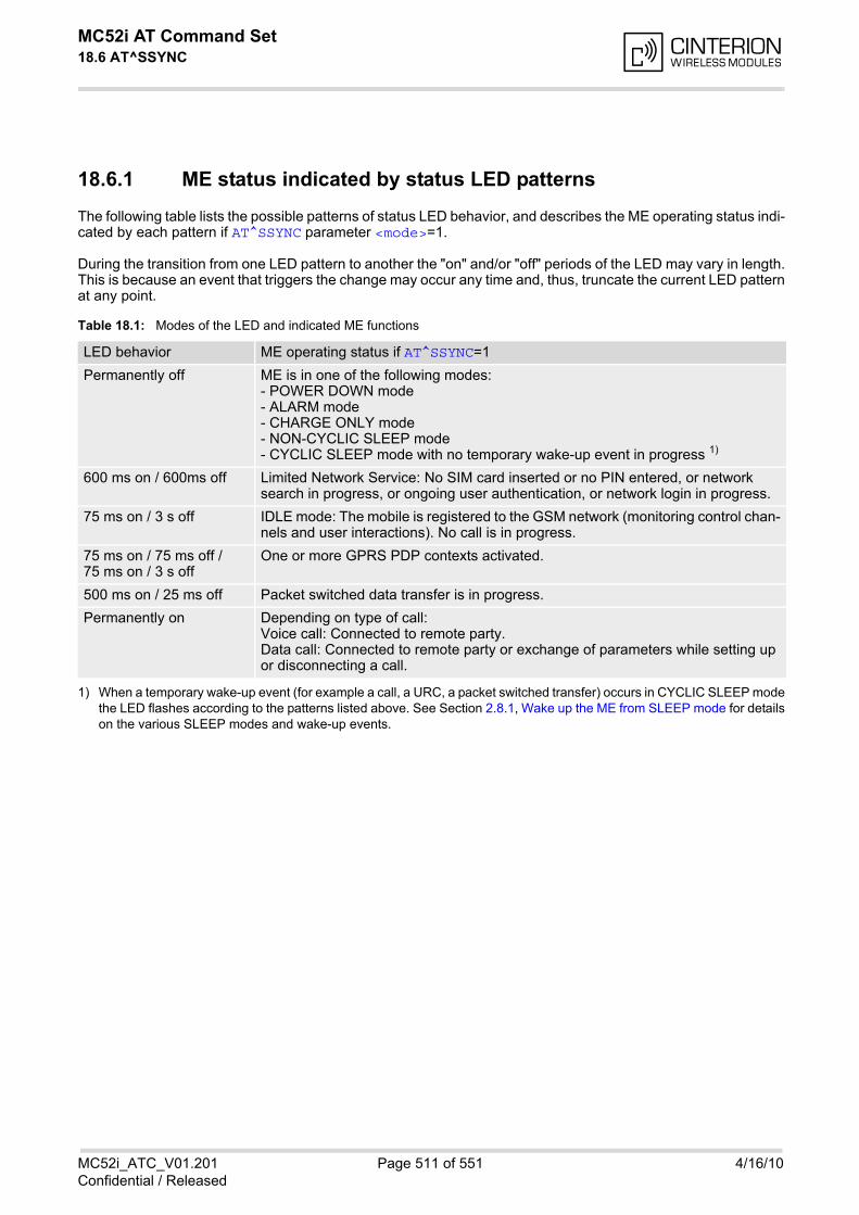
MC52i AT Command Set 18.6 AT^SSYNC
MC52i_ATC_V01.201 Page 511 of 551 4/16/10Confidential / Released
18.6.1 ME status indicated by status LED patterns
The following table lists the possible patterns of status LED behavior, and describes the ME operating status indi-cated by each pattern if AT^SSYNC parameter <mode>=1.
During the transition from one LED pattern to another the "on" and/or "off" periods of the LED may vary in length.This is because an event that triggers the change may occur any time and, thus, truncate the current LED patternat any point.
Table 18.1: Modes of the LED and indicated ME functions
1) When a temporary wake-up event (for example a call, a URC, a packet switched transfer) occurs in CYCLIC SLEEP modethe LED flashes according to the patterns listed above. See Section 2.8.1, Wake up the ME from SLEEP mode for detailson the various SLEEP modes and wake-up events.
LED behavior ME operating status if AT^SSYNC=1
Permanently off ME is in one of the following modes: - POWER DOWN mode - ALARM mode - CHARGE ONLY mode - NON-CYCLIC SLEEP mode- CYCLIC SLEEP mode with no temporary wake-up event in progress 1)
600 ms on / 600ms off Limited Network Service: No SIM card inserted or no PIN entered, or network search in progress, or ongoing user authentication, or network login in progress.
75 ms on / 3 s off IDLE mode: The mobile is registered to the GSM network (monitoring control chan-nels and user interactions). No call is in progress.
75 ms on / 75 ms off /75 ms on / 3 s off
One or more GPRS PDP contexts activated.
500 ms on / 25 ms off Packet switched data transfer is in progress.
Permanently on Depending on type of call:Voice call: Connected to remote party.Data call: Connected to remote party or exchange of parameters while setting up or disconnecting a call.
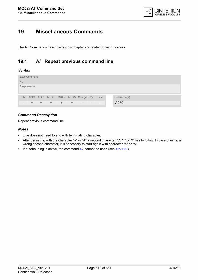
MC52i AT Command Set 19. Miscellaneous Commands
MC52i_ATC_V01.201 Page 512 of 551 4/16/10Confidential / Released
19. Miscellaneous Commands
The AT Commands described in this chapter are related to various areas.
19.1 A/ Repeat previous command line
Syntax
Command DescriptionRepeat previous command line.
Notes• Line does not need to end with terminating character.
• After beginning with the character "a" or "A" a second character "t", "T" or "/" has to follow. In case of using awrong second character, it is necessary to start again with character "a" or "A".
• If autobauding is active, the command A/ cannot be used (see AT+IPR).
Exec Command
A/Response(s)
PIN ASC0 ASC1 MUX1 MUX2 MUX3 Charge Last Reference(s)
- + + + + + - - - V.250
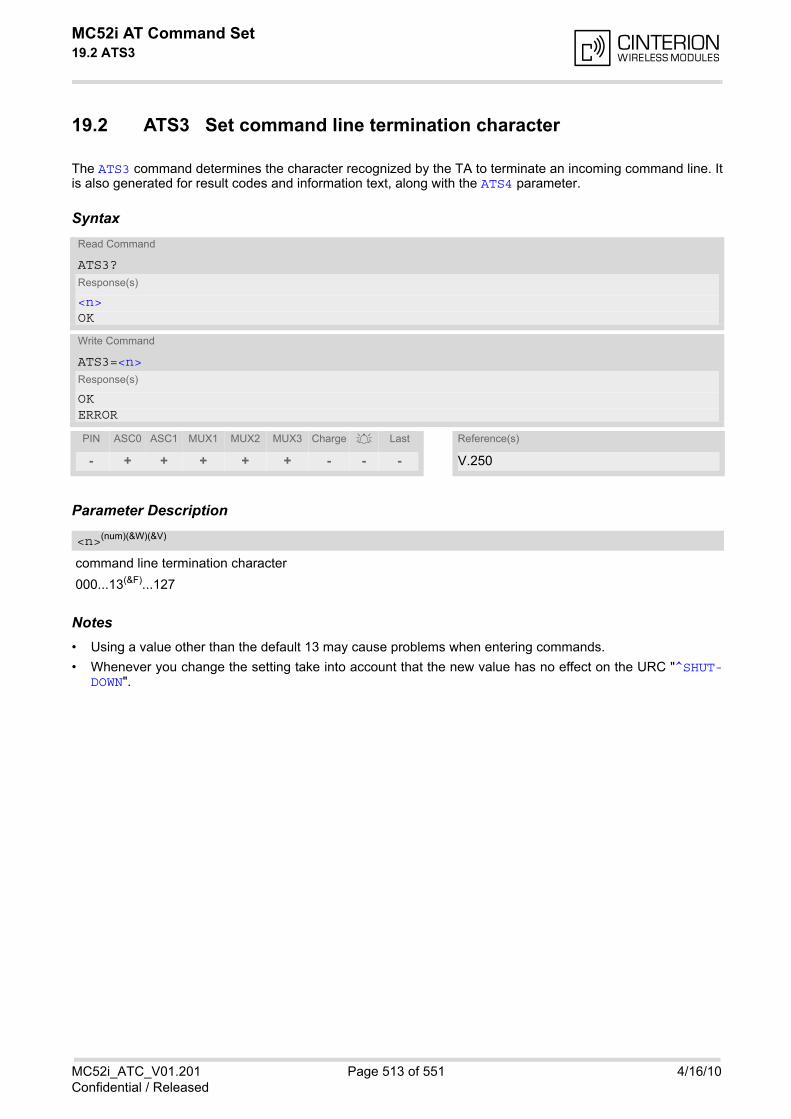
MC52i AT Command Set 19.2 ATS3
MC52i_ATC_V01.201 Page 513 of 551 4/16/10Confidential / Released
19.2 ATS3 Set command line termination character
The ATS3 command determines the character recognized by the TA to terminate an incoming command line. Itis also generated for result codes and information text, along with the ATS4 parameter.
Syntax
Parameter Description
command line termination character
000...13(&F)...127
Notes• Using a value other than the default 13 may cause problems when entering commands.
• Whenever you change the setting take into account that the new value has no effect on the URC "^SHUT-DOWN".
Read Command
ATS3?Response(s)
<n>OK
Write Command
ATS3=<n>Response(s)
OKERROR
PIN ASC0 ASC1 MUX1 MUX2 MUX3 Charge Last Reference(s)
- + + + + + - - - V.250
<n>(num)(&W)(&V)
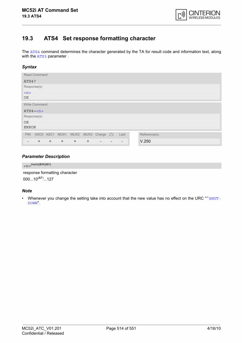
MC52i AT Command Set 19.3 ATS4
MC52i_ATC_V01.201 Page 514 of 551 4/16/10Confidential / Released
19.3 ATS4 Set response formatting character
The ATS4 command determines the character generated by the TA for result code and information text, alongwith the ATS3 parameter .
Syntax
Parameter Description
response formatting character
000...10(&F)...127
Note• Whenever you change the setting take into account that the new value has no effect on the URC "^SHUT-
DOWN".
Read Command
ATS4?Response(s)
<n>OK
Write Command
ATS4=<n>Response(s)
OKERROR
PIN ASC0 ASC1 MUX1 MUX2 MUX3 Charge Last Reference(s)
- + + + + + - - - V.250
<n>(num)(&W)(&V)
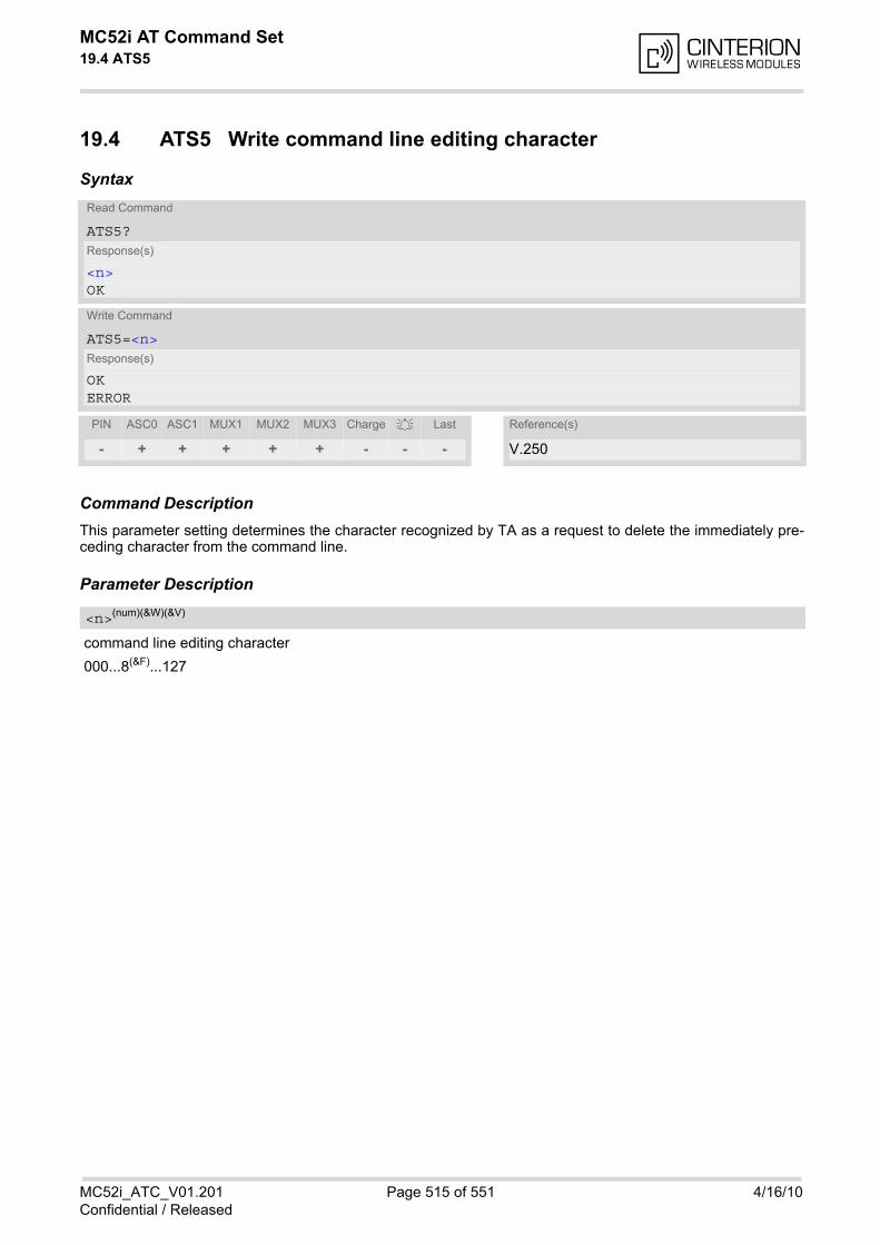
MC52i AT Command Set 19.4 ATS5
MC52i_ATC_V01.201 Page 515 of 551 4/16/10Confidential / Released
19.4 ATS5 Write command line editing character
Syntax
Command DescriptionThis parameter setting determines the character recognized by TA as a request to delete the immediately pre-ceding character from the command line.
Parameter Description
command line editing character
000...8(&F)...127
Read Command
ATS5?Response(s)
<n>OK
Write Command
ATS5=<n>Response(s)
OKERROR
PIN ASC0 ASC1 MUX1 MUX2 MUX3 Charge Last Reference(s)
- + + + + + - - - V.250
<n>(num)(&W)(&V)
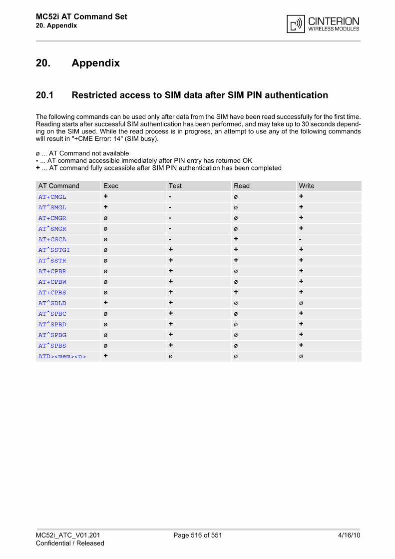
MC52i AT Command Set 20. Appendix
MC52i_ATC_V01.201 Page 516 of 551 4/16/10Confidential / Released
20. Appendix
20.1 Restricted access to SIM data after SIM PIN authentication
The following commands can be used only after data from the SIM have been read successfully for the first time.Reading starts after successful SIM authentication has been performed, and may take up to 30 seconds depend-ing on the SIM used. While the read process is in progress, an attempt to use any of the following commandswill result in "+CME Error: 14" (SIM busy).
ø ... AT Command not available- ... AT command accessible immediately after PIN entry has returned OK+ ... AT command fully accessible after SIM PIN authentication has been completed
AT Command Exec Test Read Write
AT+CMGL + - ø +
AT^SMGL + - ø +
AT+CMGR ø - ø +
AT^SMGR ø - ø +
AT+CSCA ø - + -
AT^SSTGI ø + + +
AT^SSTR ø + + +
AT+CPBR ø + ø +
AT+CPBW ø + ø +
AT+CPBS ø + + +
AT^SDLD + + ø ø
AT^SPBC ø + ø +
AT^SPBD ø + ø +
AT^SPBG ø + ø +
AT^SPBS ø + ø +
ATD><mem><n> + ø ø ø

MC52i AT Command Set 20.2 Star-Hash (*#) Network Commands
MC52i_ATC_V01.201 Page 517 of 551 4/16/10Confidential / Released
20.2 Star-Hash (*#) Network Commands
The following command strings can be sent to the network via ATD and have to be terminated with a semicolon.The command strings are defined with GSM 2.30 [16].
Table 20.1: Star-Hash (*#) Command Overview
Star-Hash Code Functionality Response, also refer to Table 20.3
Phone Security
*#06# Query IMEI <IMEI> OK
**04[2]*oldPin[2]*newPin[2]*new-Pin[2]#
Change SIM pwd +CME ERROR: <err> / OK
**05[2]*unblKey[2]*newPin[2]*new-Pin[2]#
Change/Unblocking SIM pwd +CME ERROR: <err> / OK
*#0003*MasterPhoneCode# Unlock ''PS'' lock with Master Phone Code
+CME ERROR: <err> / OK
*[*]03*[ZZ]*oldPw*newPw*newPw# Registration of net password +CME ERROR: <err> / OK
Phone number presentation
*#30# Check status of CLIP (Calling Line Identification Presentation)
+CLIP : <n>,<m> OK (see AT+CLIP)
*#31# Check status of CLIR (Calling Line Identification Restriction)
+CLIR : <n>,<m> OK (see AT+CLIR)
*31#<Phonenumber>[;] Suppress CLIR (see AT+CLIR)
#31#<Phonenumber>[;] Activate CLIR (see AT+CLIR)
*#76# Check status of COLP (Connected Line Identification Presentation)
+COLP : <n>,<m> OK (see: AT+COLP)
*#77# Check status of COLR (Connected Line Identification Restriction)
+COLR : 0,<m> OK (where <m> = active or not active)
Call forwarding
(choice of *,#,*#,**,##)21*DN*BS# Act/deact/int/reg/eras CFU ^SCCFC : <reason>, <status>, <class> [,...] like +CCFC *) (see: AT+CCFC)
(choice of *,#,*#,**,##)67*DN*BS# Act/deact/int/reg/eras CF busy see above
(choice of *,#,*#,**,##)61*DN*BS*T#
Act/deact/int/reg/eras CF no reply see above
(choice of *,#,*#,**,##)62*DN*BS# Act/deact/int/reg/eras CF no reach see above
(choice of *,#,*#,**,##)002*DN*BS*T#
Act/deact/int/reg/eras CF all see above
(choice of *,#,*#,**,##)004*DN*BS*T#
Act/deact/int/reg/eras CF all cond. see above
Call waiting
(choice of *,#,*#)43*BS# Activation/deactivation/int WAIT +CCWA : <status>, <class> [,...] like +CCWA *) (see: AT+CCWA)

MC52i AT Command Set 20.2 Star-Hash (*#) Network Commands
MC52i_ATC_V01.201 Page 518 of 551 4/16/10Confidential / Released
*) Notes on ^SCCFC, +CCWA, ^SCLCK: The output depends on the affected basic service of the Star-Hash code. One linewill be output for every tele- or bearer service coded in basic service code BS.^SCCFC and ^SCLCK are modified by giving an additional <reason> or <fac> in front of the regular output string gener-ated by the standard commands +CCFC and +CLCK.
Table 20.2: Abbreviations of Codes and Parameters used in Table 20.1
Call barring
(choice of *,#,*#)33*Pw*BS# Act/deact/int BAOC ^SCLCK : <fac>, <status>, <class> [, ...] like +CLCK *) (Refer to AT+CLCK)
(choice of *,#,*#)331*Pw*BS# Act/deact/int BAOIC see above
(choice of *,#,*#)332*Pw*BS# Act/deact/int BAOIC exc.home see above
(choice of *,#,*#)35*Pw*BS# Act/deact/int. BAIC see above
(choice of *,#,*#)351*Pw*BS# Act/deact/int BAIC roaming see above
#330*Pw*BS# Deact. All Barring Services see above
#333*Pw*BS# Deact. All Outg.Barring Services see above
#353*Pw*BS# Deact. All Inc.Barring Services see above
Call Hold / Multiparty
C[C] in call Call hold and multiparty +CME ERROR: <err> / OK
USSD messages
[C]...[C]# Send USSD message +CME ERROR: <err> / OK
C[C] (excluded 1[C]) Send USSD message +CME ERROR: <err> / OK
Abbreviation Meaning Value
ZZ Type of supplementary services:Barring servicesAll services
330Not specified
DN Dialing number String of digits 0-9
BS Basic service equivalent to parameter class:VoiceFAXSMSSMS+FAXData circuit asynchronData circuit synchrondedicated PAD accessdedicated Packet accessData circuit asynchron+PADData circuit synchron+PacketData circuit asynchron+synchron+Packet+PADAll Services
1113161225242726212220--
T Time in seconds In contrast to AT+CCFC, parameter T has no default value. If T is not specified, an operator defined default or the last known value may be used, depending on the network operator.
Star-Hash Code Functionality Response, also refer to Table 20.3
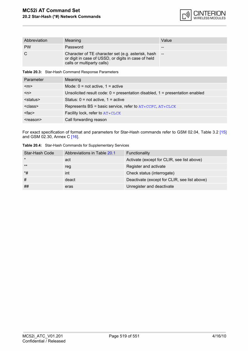
MC52i AT Command Set 20.2 Star-Hash (*#) Network Commands
MC52i_ATC_V01.201 Page 519 of 551 4/16/10Confidential / Released
Table 20.3: Star-Hash Command Response Parameters
For exact specification of format and parameters for Star-Hash commands refer to GSM 02.04, Table 3.2 [15]and GSM 02.30, Annex C [16].
Table 20.4: Star-Hash Commands for Supplementary Services
PW Password --
C Character of TE character set (e.g. asterisk, hash or digit in case of USSD, or digits in case of held calls or multiparty calls)
--
Parameter Meaning
<m> Mode: 0 = not active, 1 = active
<n> Unsolicited result code: 0 = presentation disabled, 1 = presentation enabled
<status> Status: 0 = not active, 1 = active
<class> Represents BS = basic service, refer to AT+CCFC, AT+CLCK
<fac> Facility lock, refer to AT+CLCK
<reason> Call forwarding reason
Star-Hash Code Abbreviations in Table 20.1 Functionality
* act Activate (except for CLIR, see list above)
** reg Register and activate
*# int Check status (interrogate)
# deact Deactivate (except for CLIR, see list above)
## eras Unregister and deactivate
Abbreviation Meaning Value
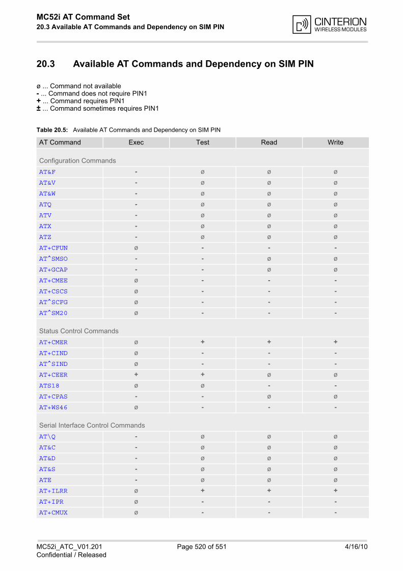
MC52i AT Command Set 20.3 Available AT Commands and Dependency on SIM PIN
MC52i_ATC_V01.201 Page 520 of 551 4/16/10Confidential / Released
20.3 Available AT Commands and Dependency on SIM PIN
ø ... Command not available- ... Command does not require PIN1+ ... Command requires PIN1± ... Command sometimes requires PIN1
Table 20.5: Available AT Commands and Dependency on SIM PIN
AT Command Exec Test Read Write
Configuration Commands
AT&F - ø ø ø
AT&V - ø ø ø
AT&W - ø ø ø
ATQ - ø ø ø
ATV - ø ø ø
ATX - ø ø ø
ATZ - ø ø ø
AT+CFUN ø - - -
AT^SMSO - - ø ø
AT+GCAP - - ø ø
AT+CMEE ø - - -
AT+CSCS ø - - -
AT^SCFG ø - - -
AT^SM20 ø - - -
Status Control Commands
AT+CMER ø + + +
AT+CIND ø - - -
AT^SIND ø - - -
AT+CEER + + ø ø
ATS18 ø ø - -
AT+CPAS - - ø ø
AT+WS46 ø - - -
Serial Interface Control Commands
AT\Q - ø ø ø
AT&C - ø ø ø
AT&D - ø ø ø
AT&S - ø ø ø
ATE - ø ø ø
AT+ILRR ø + + +
AT+IPR ø - - -
AT+CMUX ø - - -
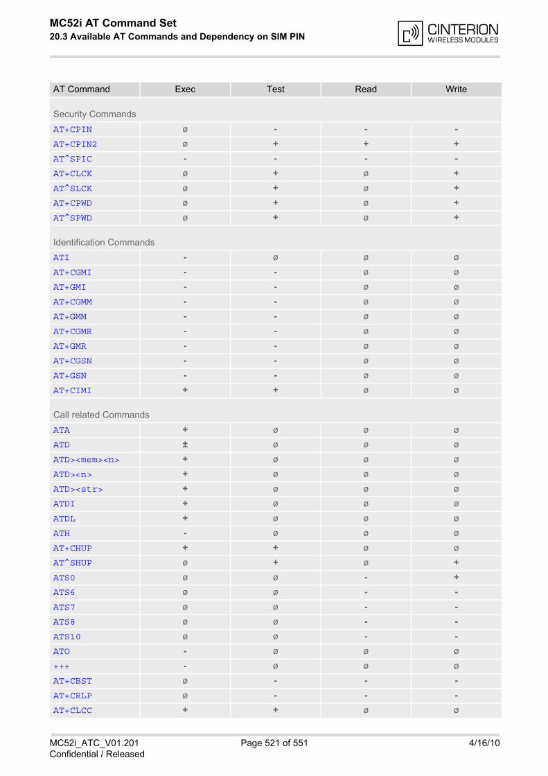
MC52i AT Command Set 20.3 Available AT Commands and Dependency on SIM PIN
MC52i_ATC_V01.201 Page 521 of 551 4/16/10Confidential / Released
Security Commands
AT+CPIN ø - - -
AT+CPIN2 ø + + +
AT^SPIC - - - -
AT+CLCK ø + ø +
AT^SLCK ø + ø +
AT+CPWD ø + ø +
AT^SPWD ø + ø +
Identification Commands
ATI - ø ø ø
AT+CGMI - - ø ø
AT+GMI - - ø ø
AT+CGMM - - ø ø
AT+GMM - - ø ø
AT+CGMR - - ø ø
AT+GMR - - ø ø
AT+CGSN - - ø ø
AT+GSN - - ø ø
AT+CIMI + + ø ø
Call related Commands
ATA + ø ø ø
ATD ± ø ø ø
ATD><mem><n> + ø ø ø
ATD><n> + ø ø ø
ATD><str> + ø ø ø
ATDI + ø ø ø
ATDL + ø ø ø
ATH - ø ø ø
AT+CHUP + + ø ø
AT^SHUP ø + ø +
ATS0 ø ø - +
ATS6 ø ø - -
ATS7 ø ø - -
ATS8 ø ø - -
ATS10 ø ø - -
ATO - ø ø ø
+++ - ø ø ø
AT+CBST ø - - -
AT+CRLP ø - - -
AT+CLCC + + ø ø
AT Command Exec Test Read Write
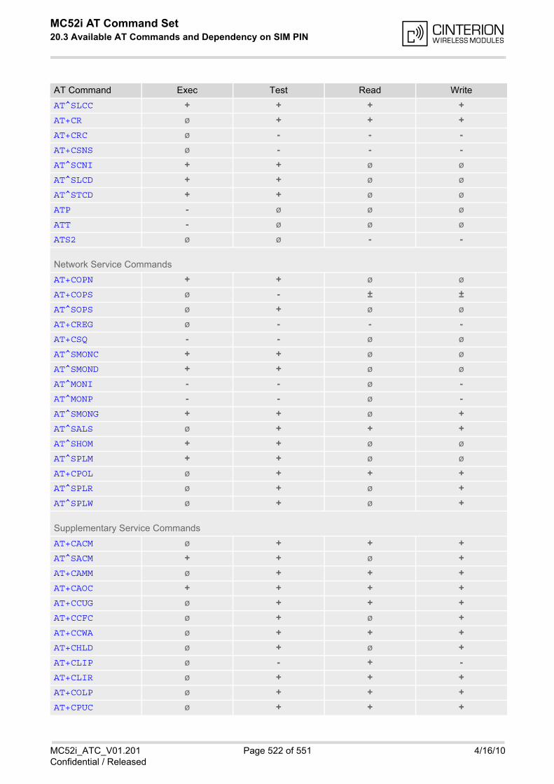
MC52i AT Command Set 20.3 Available AT Commands and Dependency on SIM PIN
MC52i_ATC_V01.201 Page 522 of 551 4/16/10Confidential / Released
AT^SLCC + + + +
AT+CR ø + + +
AT+CRC ø - - -
AT+CSNS ø - - -
AT^SCNI + + ø ø
AT^SLCD + + ø ø
AT^STCD + + ø ø
ATP - ø ø ø
ATT - ø ø ø
ATS2 ø ø - -
Network Service Commands
AT+COPN + + ø ø
AT+COPS ø - ± ±
AT^SOPS ø + ø ø
AT+CREG ø - - -
AT+CSQ - - ø ø
AT^SMONC + + ø ø
AT^SMOND + + ø ø
AT^MONI - - ø -
AT^MONP - - ø -
AT^SMONG + + ø +
AT^SALS ø + + +
AT^SHOM + + ø ø
AT^SPLM + + ø ø
AT+CPOL ø + + +
AT^SPLR ø + ø +
AT^SPLW ø + ø +
Supplementary Service Commands
AT+CACM ø + + +
AT^SACM + + ø +
AT+CAMM ø + + +
AT+CAOC + + + +
AT+CCUG ø + + +
AT+CCFC ø + ø +
AT+CCWA ø + + +
AT+CHLD ø + ø +
AT+CLIP ø - + -
AT+CLIR ø + + +
AT+COLP ø + + +
AT+CPUC ø + + +
AT Command Exec Test Read Write
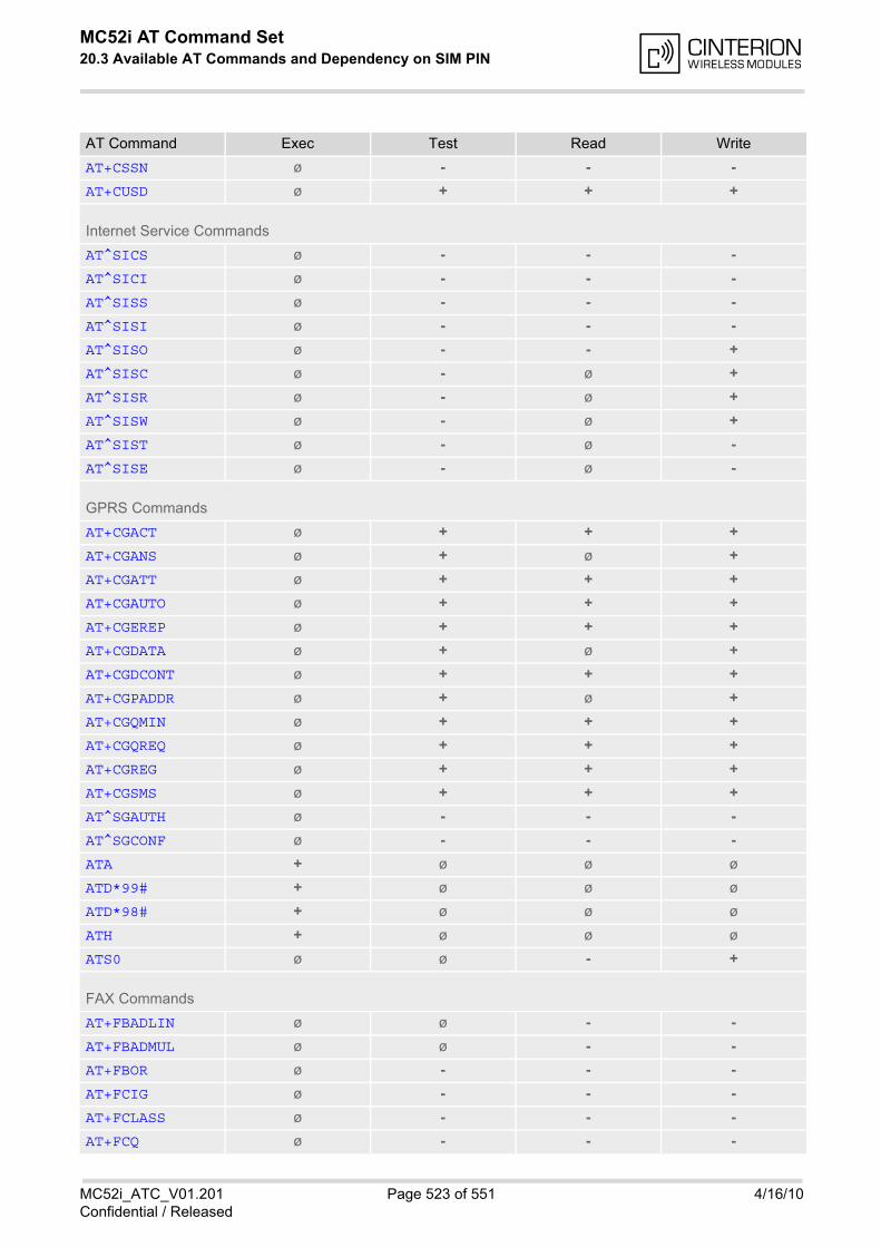
MC52i AT Command Set 20.3 Available AT Commands and Dependency on SIM PIN
MC52i_ATC_V01.201 Page 523 of 551 4/16/10Confidential / Released
AT+CSSN ø - - -
AT+CUSD ø + + +
Internet Service Commands
AT^SICS ø - - -
AT^SICI ø - - -
AT^SISS ø - - -
AT^SISI ø - - -
AT^SISO ø - - +
AT^SISC ø - ø +
AT^SISR ø - ø +
AT^SISW ø - ø +
AT^SIST ø - ø -
AT^SISE ø - ø -
GPRS Commands
AT+CGACT ø + + +
AT+CGANS ø + ø +
AT+CGATT ø + + +
AT+CGAUTO ø + + +
AT+CGEREP ø + + +
AT+CGDATA ø + ø +
AT+CGDCONT ø + + +
AT+CGPADDR ø + ø +
AT+CGQMIN ø + + +
AT+CGQREQ ø + + +
AT+CGREG ø + + +
AT+CGSMS ø + + +
AT^SGAUTH ø - - -
AT^SGCONF ø - - -
ATA + ø ø ø
ATD*99# + ø ø ø
ATD*98# + ø ø ø
ATH + ø ø ø
ATS0 ø ø - +
FAX Commands
AT+FBADLIN ø ø - -
AT+FBADMUL ø ø - -
AT+FBOR ø - - -
AT+FCIG ø - - -
AT+FCLASS ø - - -
AT+FCQ ø - - -
AT Command Exec Test Read Write

MC52i AT Command Set 20.3 Available AT Commands and Dependency on SIM PIN
MC52i_ATC_V01.201 Page 524 of 551 4/16/10Confidential / Released
AT+FCR ø ø ø -
AT+FDCC ø - - -
AT+FDFFC ø - - -
AT+FDIS ø - - -
AT+FDR - ø ø ø
AT+FDT - ø ø -
AT+FET ø ø ø -
AT+FK - ø ø ø
AT+FLID ø - - -
AT+FMDL ø ø - ø
AT+FMFR ø ø - ø
AT+FOPT ø ø ø -
AT+FPHCTO ø ø - -
AT+FREV ø ø - ø
AT+FRH ø - ø -
AT+FRM ø - ø -
AT+FRS ø ø ø -
AT+FTH ø - ø -
AT+FTM ø - ø -
AT+FTS ø ø ø -
AT+FVRFC ø - - -
Short Message Service (SMS) Commands
AT+CMGC ø + ø +
AT+CMGD ø + ø +
AT+CMGF ø - - -
AT+CMGL + + ø +
AT+CMGR ø + ø +
AT+CMGS ø + ø +
AT+CMGW + + ø +
AT+CMSS ø + ø +
AT+CNMA + + ø +
AT+CNMI ø + + +
AT+CPMS ø + + +
AT+CSCA ø + + +
AT+CSCB ø + + +
AT+CSDH ø + + +
AT+CSMP ø + + +
AT+CSMS ø + + +
AT^SLMS + + ø ø
AT^SMGL + + ø +
AT^SMGO ø + + +
AT Command Exec Test Read Write
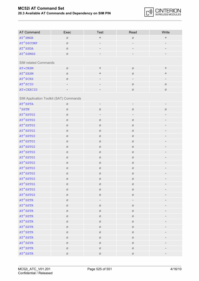
MC52i AT Command Set 20.3 Available AT Commands and Dependency on SIM PIN
MC52i_ATC_V01.201 Page 525 of 551 4/16/10Confidential / Released
AT^SMGR ø + ø +
AT^SSCONF ø - - -
AT^SSDA ø - - -
AT^SSMSS ø - - -
SIM related Commands
AT+CRSM ø + ø +
AT^SXSM ø + ø +
AT^SCKS ø - - -
AT^SCID - - ø ø
AT+CXXCID - - ø ø
SIM Application Toolkit (SAT) Commands
AT^SSTA ø - - -
^SSTN ø ø ø ø
AT^SSTGI ø - - -
AT^SSTGI ø ø ø -
AT^SSTGI ø ø ø -
AT^SSTGI ø ø ø -
AT^SSTGI ø ø ø -
AT^SSTGI ø ø ø -
AT^SSTGI ø ø ø -
AT^SSTGI ø ø ø -
AT^SSTGI ø ø ø -
AT^SSTGI ø ø ø -
AT^SSTGI ø ø ø -
AT^SSTGI ø ø ø -
AT^SSTGI ø ø ø -
AT^SSTGI ø ø ø -
AT^SSTGI ø ø ø -
AT^SSTGI ø ø ø -
AT^SSTR ø - - -
AT^SSTR ø ø ø -
AT^SSTR ø ø ø -
AT^SSTR ø ø ø -
AT^SSTR ø ø ø -
AT^SSTR ø ø ø -
AT^SSTR ø ø ø -
AT^SSTR ø ø ø -
AT^SSTR ø ø ø -
AT^SSTR ø ø ø -
AT^SSTR ø ø ø -
AT Command Exec Test Read Write
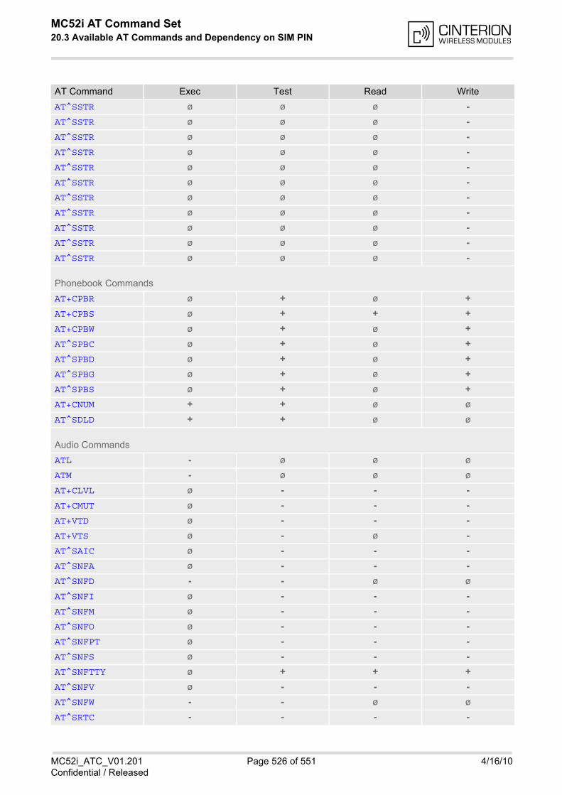
MC52i AT Command Set 20.3 Available AT Commands and Dependency on SIM PIN
MC52i_ATC_V01.201 Page 526 of 551 4/16/10Confidential / Released
AT^SSTR ø ø ø -
AT^SSTR ø ø ø -
AT^SSTR ø ø ø -
AT^SSTR ø ø ø -
AT^SSTR ø ø ø -
AT^SSTR ø ø ø -
AT^SSTR ø ø ø -
AT^SSTR ø ø ø -
AT^SSTR ø ø ø -
AT^SSTR ø ø ø -
AT^SSTR ø ø ø -
Phonebook Commands
AT+CPBR ø + ø +
AT+CPBS ø + + +
AT+CPBW ø + ø +
AT^SPBC ø + ø +
AT^SPBD ø + ø +
AT^SPBG ø + ø +
AT^SPBS ø + ø +
AT+CNUM + + ø ø
AT^SDLD + + ø ø
Audio Commands
ATL - ø ø ø
ATM - ø ø ø
AT+CLVL ø - - -
AT+CMUT ø - - -
AT+VTD ø - - -
AT+VTS ø - ø -
AT^SAIC ø - - -
AT^SNFA ø - - -
AT^SNFD - - ø ø
AT^SNFI ø - - -
AT^SNFM ø - - -
AT^SNFO ø - - -
AT^SNFPT ø - - -
AT^SNFS ø - - -
AT^SNFTTY ø + + +
AT^SNFV ø - - -
AT^SNFW - - ø ø
AT^SRTC - - - -
AT Command Exec Test Read Write
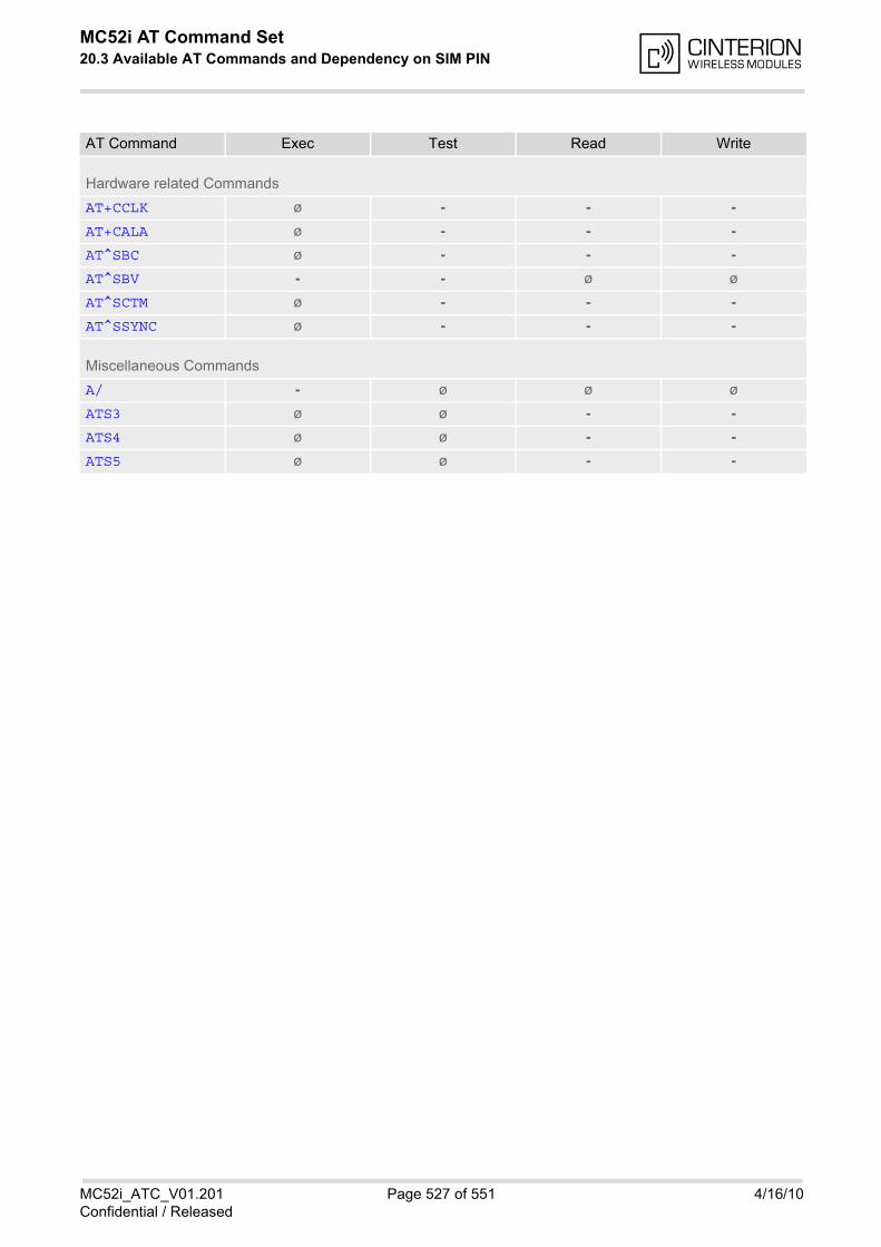
MC52i AT Command Set 20.3 Available AT Commands and Dependency on SIM PIN
MC52i_ATC_V01.201 Page 527 of 551 4/16/10Confidential / Released
Hardware related Commands
AT+CCLK ø - - -
AT+CALA ø - - -
AT^SBC ø - - -
AT^SBV - - ø ø
AT^SCTM ø - - -
AT^SSYNC ø - - -
Miscellaneous Commands
A/ - ø ø ø
ATS3 ø ø - -
ATS4 ø ø - -
ATS5 ø ø - -
AT Command Exec Test Read Write
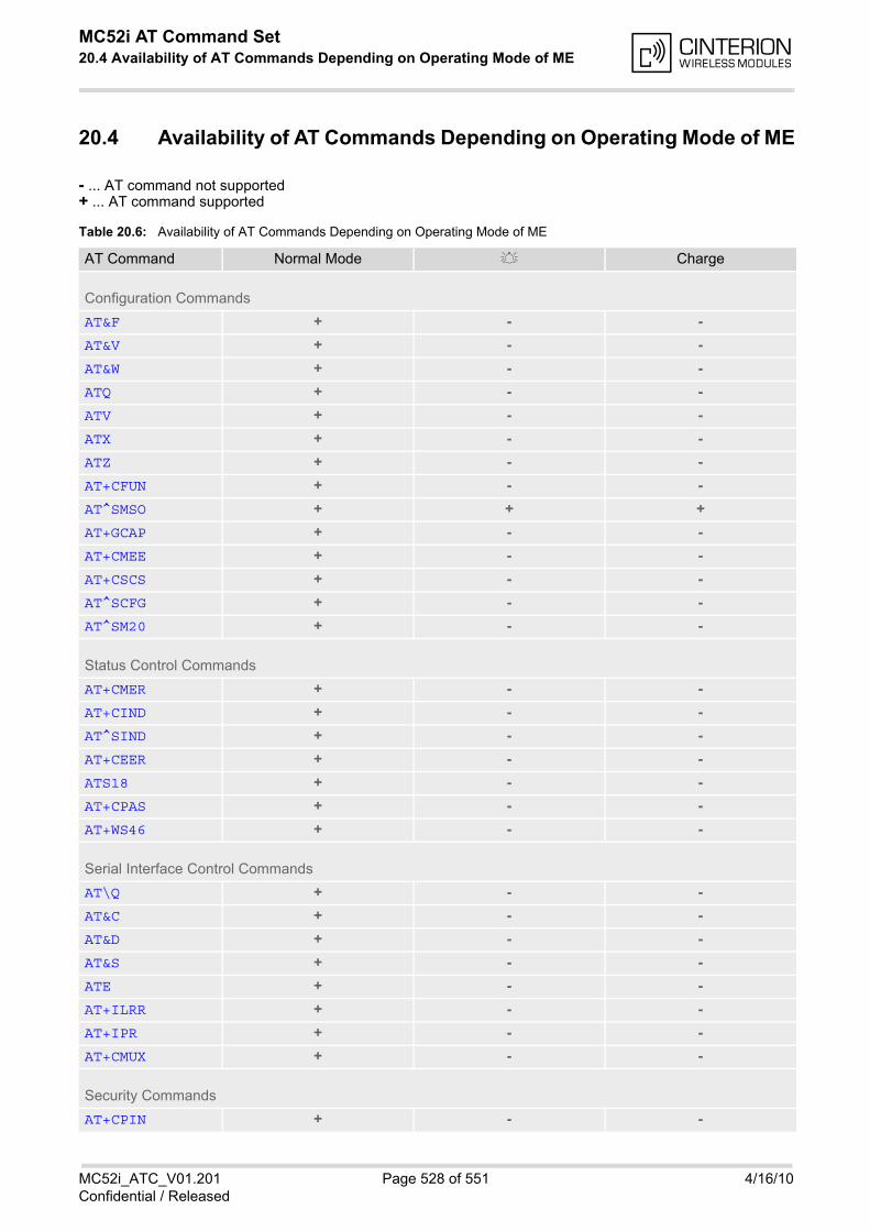
MC52i AT Command Set 20.4 Availability of AT Commands Depending on Operating Mode of ME
MC52i_ATC_V01.201 Page 528 of 551 4/16/10Confidential / Released
20.4 Availability of AT Commands Depending on Operating Mode of ME
- ... AT command not supported+ ... AT command supported
Table 20.6: Availability of AT Commands Depending on Operating Mode of ME
AT Command Normal Mode Charge
Configuration Commands
AT&F + - -
AT&V + - -
AT&W + - -
ATQ + - -
ATV + - -
ATX + - -
ATZ + - -
AT+CFUN + - -
AT^SMSO + + +
AT+GCAP + - -
AT+CMEE + - -
AT+CSCS + - -
AT^SCFG + - -
AT^SM20 + - -
Status Control Commands
AT+CMER + - -
AT+CIND + - -
AT^SIND + - -
AT+CEER + - -
ATS18 + - -
AT+CPAS + - -
AT+WS46 + - -
Serial Interface Control Commands
AT\Q + - -
AT&C + - -
AT&D + - -
AT&S + - -
ATE + - -
AT+ILRR + - -
AT+IPR + - -
AT+CMUX + - -
Security Commands
AT+CPIN + - -

MC52i AT Command Set 20.4 Availability of AT Commands Depending on Operating Mode of ME
MC52i_ATC_V01.201 Page 529 of 551 4/16/10Confidential / Released
AT+CPIN2 + - -
AT^SPIC + - -
AT+CLCK + - -
AT^SLCK + - -
AT+CPWD + - -
AT^SPWD + - -
Identification Commands
ATI + - -
AT+CGMI + - -
AT+GMI + - -
AT+CGMM + - -
AT+GMM + - -
AT+CGMR + - -
AT+GMR + - -
AT+CGSN + - -
AT+GSN + - -
AT+CIMI + - -
Call related Commands
ATA + - -
ATD + - -
ATD><mem><n> + - -
ATD><n> + - -
ATD><str> + - -
ATDI + - -
ATDL + - -
ATH + - -
AT+CHUP + - -
AT^SHUP + - -
ATS0 + - -
ATS6 + - -
ATS7 + - -
ATS8 + - -
ATS10 + - -
ATO + - -
+++ + - -
AT+CBST + - -
AT+CRLP + - -
AT+CLCC + - -
AT^SLCC + - -
AT+CR + - -
AT Command Normal Mode Charge
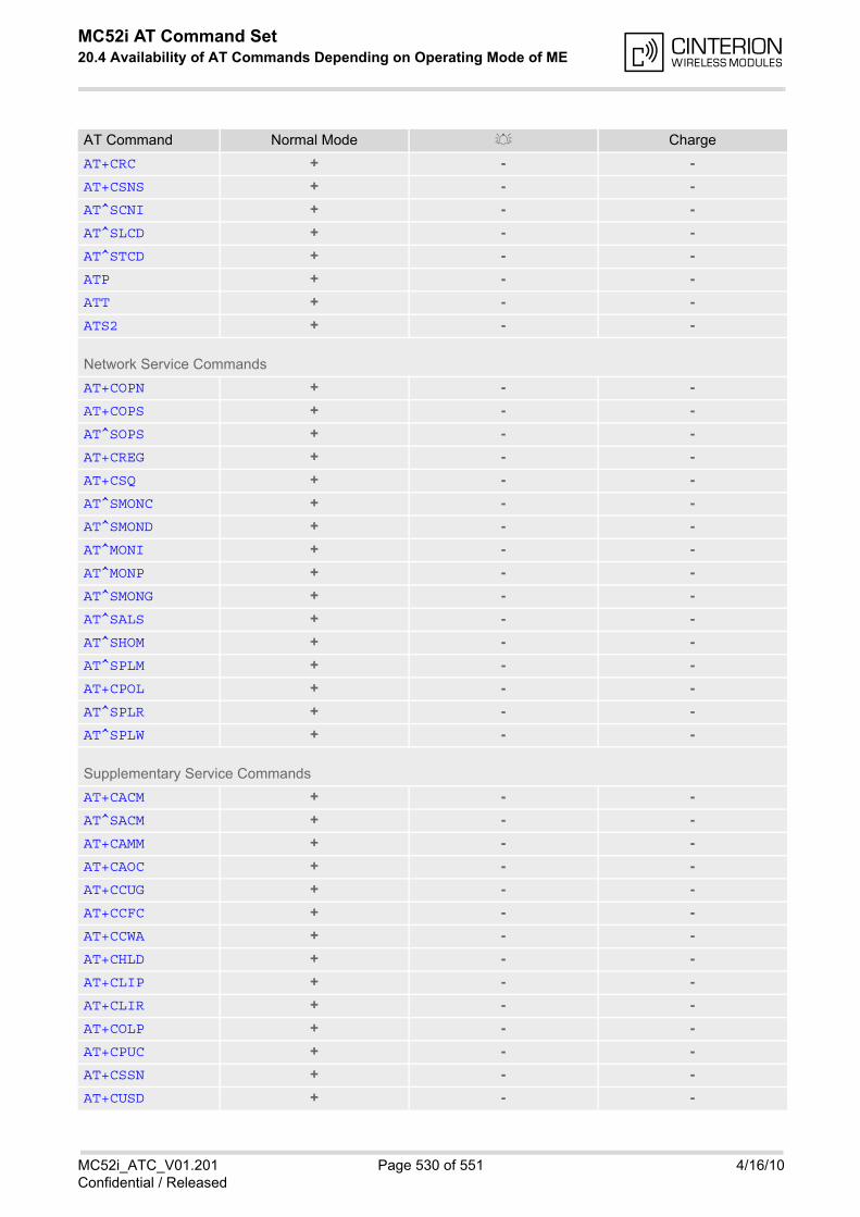
MC52i AT Command Set 20.4 Availability of AT Commands Depending on Operating Mode of ME
MC52i_ATC_V01.201 Page 530 of 551 4/16/10Confidential / Released
AT+CRC + - -
AT+CSNS + - -
AT^SCNI + - -
AT^SLCD + - -
AT^STCD + - -
ATP + - -
ATT + - -
ATS2 + - -
Network Service Commands
AT+COPN + - -
AT+COPS + - -
AT^SOPS + - -
AT+CREG + - -
AT+CSQ + - -
AT^SMONC + - -
AT^SMOND + - -
AT^MONI + - -
AT^MONP + - -
AT^SMONG + - -
AT^SALS + - -
AT^SHOM + - -
AT^SPLM + - -
AT+CPOL + - -
AT^SPLR + - -
AT^SPLW + - -
Supplementary Service Commands
AT+CACM + - -
AT^SACM + - -
AT+CAMM + - -
AT+CAOC + - -
AT+CCUG + - -
AT+CCFC + - -
AT+CCWA + - -
AT+CHLD + - -
AT+CLIP + - -
AT+CLIR + - -
AT+COLP + - -
AT+CPUC + - -
AT+CSSN + - -
AT+CUSD + - -
AT Command Normal Mode Charge
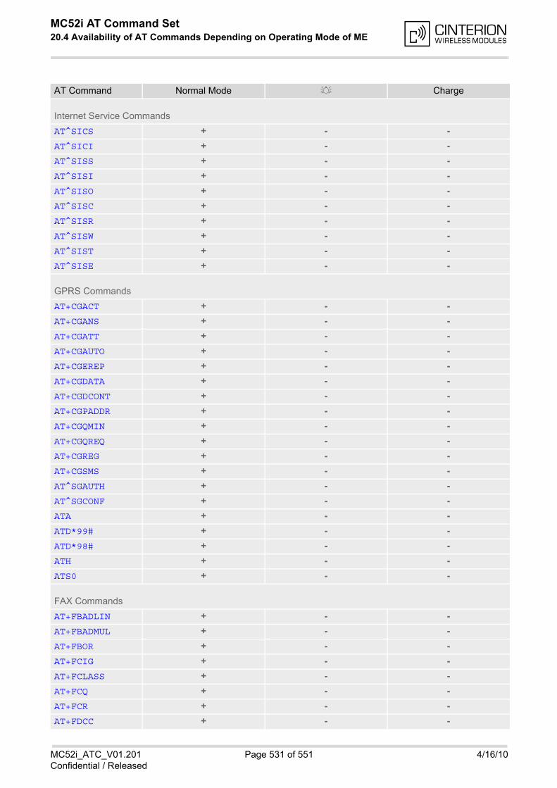
MC52i AT Command Set 20.4 Availability of AT Commands Depending on Operating Mode of ME
MC52i_ATC_V01.201 Page 531 of 551 4/16/10Confidential / Released
Internet Service Commands
AT^SICS + - -
AT^SICI + - -
AT^SISS + - -
AT^SISI + - -
AT^SISO + - -
AT^SISC + - -
AT^SISR + - -
AT^SISW + - -
AT^SIST + - -
AT^SISE + - -
GPRS Commands
AT+CGACT + - -
AT+CGANS + - -
AT+CGATT + - -
AT+CGAUTO + - -
AT+CGEREP + - -
AT+CGDATA + - -
AT+CGDCONT + - -
AT+CGPADDR + - -
AT+CGQMIN + - -
AT+CGQREQ + - -
AT+CGREG + - -
AT+CGSMS + - -
AT^SGAUTH + - -
AT^SGCONF + - -
ATA + - -
ATD*99# + - -
ATD*98# + - -
ATH + - -
ATS0 + - -
FAX Commands
AT+FBADLIN + - -
AT+FBADMUL + - -
AT+FBOR + - -
AT+FCIG + - -
AT+FCLASS + - -
AT+FCQ + - -
AT+FCR + - -
AT+FDCC + - -
AT Command Normal Mode Charge
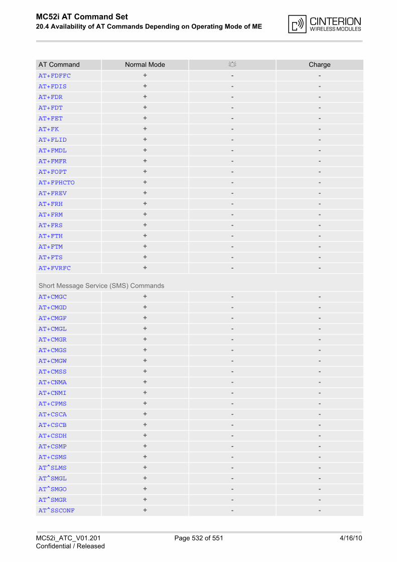
MC52i AT Command Set 20.4 Availability of AT Commands Depending on Operating Mode of ME
MC52i_ATC_V01.201 Page 532 of 551 4/16/10Confidential / Released
AT+FDFFC + - -
AT+FDIS + - -
AT+FDR + - -
AT+FDT + - -
AT+FET + - -
AT+FK + - -
AT+FLID + - -
AT+FMDL + - -
AT+FMFR + - -
AT+FOPT + - -
AT+FPHCTO + - -
AT+FREV + - -
AT+FRH + - -
AT+FRM + - -
AT+FRS + - -
AT+FTH + - -
AT+FTM + - -
AT+FTS + - -
AT+FVRFC + - -
Short Message Service (SMS) Commands
AT+CMGC + - -
AT+CMGD + - -
AT+CMGF + - -
AT+CMGL + - -
AT+CMGR + - -
AT+CMGS + - -
AT+CMGW + - -
AT+CMSS + - -
AT+CNMA + - -
AT+CNMI + - -
AT+CPMS + - -
AT+CSCA + - -
AT+CSCB + - -
AT+CSDH + - -
AT+CSMP + - -
AT+CSMS + - -
AT^SLMS + - -
AT^SMGL + - -
AT^SMGO + - -
AT^SMGR + - -
AT^SSCONF + - -
AT Command Normal Mode Charge

MC52i AT Command Set 20.4 Availability of AT Commands Depending on Operating Mode of ME
MC52i_ATC_V01.201 Page 533 of 551 4/16/10Confidential / Released
AT^SSDA + - -
AT^SSMSS + - -
SIM related Commands
AT+CRSM + - -
AT^SXSM + - -
AT^SCKS + - -
AT^SCID + - -
AT+CXXCID + - -
SIM Application Toolkit (SAT) Commands
AT^SSTA + - -
^SSTN + - -
AT^SSTGI + - -
AT^SSTGI + - -
AT^SSTGI + - -
AT^SSTGI + - -
AT^SSTGI + - -
AT^SSTGI + - -
AT^SSTGI + - -
AT^SSTGI + - -
AT^SSTGI + - -
AT^SSTGI + - -
AT^SSTGI + - -
AT^SSTGI + - -
AT^SSTGI + - -
AT^SSTGI + - -
AT^SSTGI + - -
AT^SSTGI + - -
AT^SSTR + - -
AT^SSTR + - -
AT^SSTR + - -
AT^SSTR + - -
AT^SSTR + - -
AT^SSTR + - -
AT^SSTR + - -
AT^SSTR + - -
AT^SSTR + - -
AT^SSTR + - -
AT^SSTR + - -
AT^SSTR + - -
AT^SSTR + - -
AT Command Normal Mode Charge
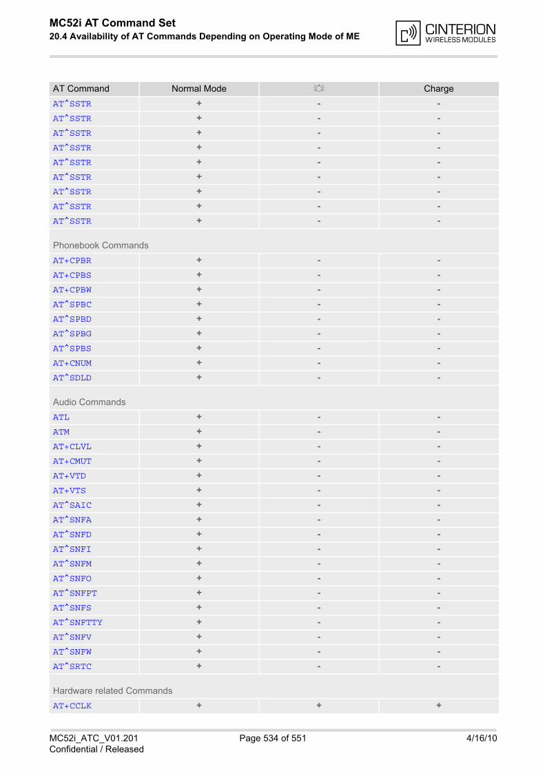
MC52i AT Command Set 20.4 Availability of AT Commands Depending on Operating Mode of ME
MC52i_ATC_V01.201 Page 534 of 551 4/16/10Confidential / Released
AT^SSTR + - -
AT^SSTR + - -
AT^SSTR + - -
AT^SSTR + - -
AT^SSTR + - -
AT^SSTR + - -
AT^SSTR + - -
AT^SSTR + - -
AT^SSTR + - -
Phonebook Commands
AT+CPBR + - -
AT+CPBS + - -
AT+CPBW + - -
AT^SPBC + - -
AT^SPBD + - -
AT^SPBG + - -
AT^SPBS + - -
AT+CNUM + - -
AT^SDLD + - -
Audio Commands
ATL + - -
ATM + - -
AT+CLVL + - -
AT+CMUT + - -
AT+VTD + - -
AT+VTS + - -
AT^SAIC + - -
AT^SNFA + - -
AT^SNFD + - -
AT^SNFI + - -
AT^SNFM + - -
AT^SNFO + - -
AT^SNFPT + - -
AT^SNFS + - -
AT^SNFTTY + - -
AT^SNFV + - -
AT^SNFW + - -
AT^SRTC + - -
Hardware related Commands
AT+CCLK + + +
AT Command Normal Mode Charge
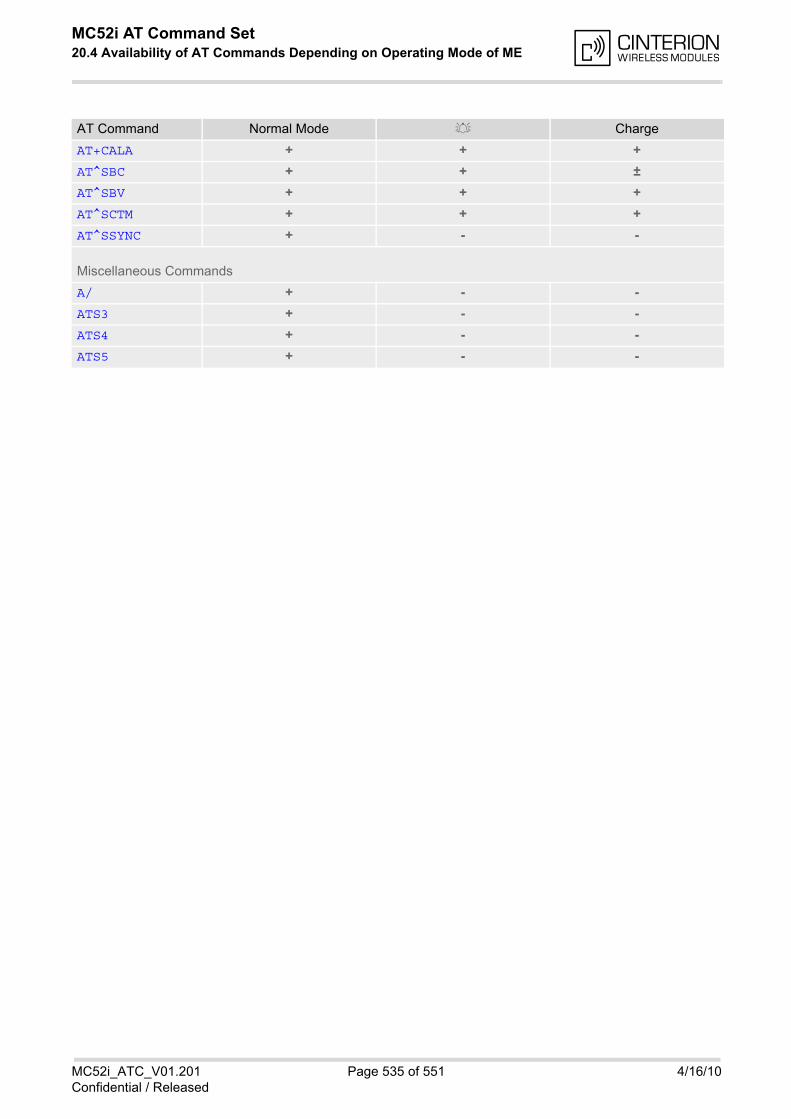
MC52i AT Command Set 20.4 Availability of AT Commands Depending on Operating Mode of ME
MC52i_ATC_V01.201 Page 535 of 551 4/16/10Confidential / Released
AT+CALA + + +
AT^SBC + + ±
AT^SBV + + +
AT^SCTM + + +
AT^SSYNC + - -
Miscellaneous Commands
A/ + - -
ATS3 + - -
ATS4 + - -
ATS5 + - -
AT Command Normal Mode Charge
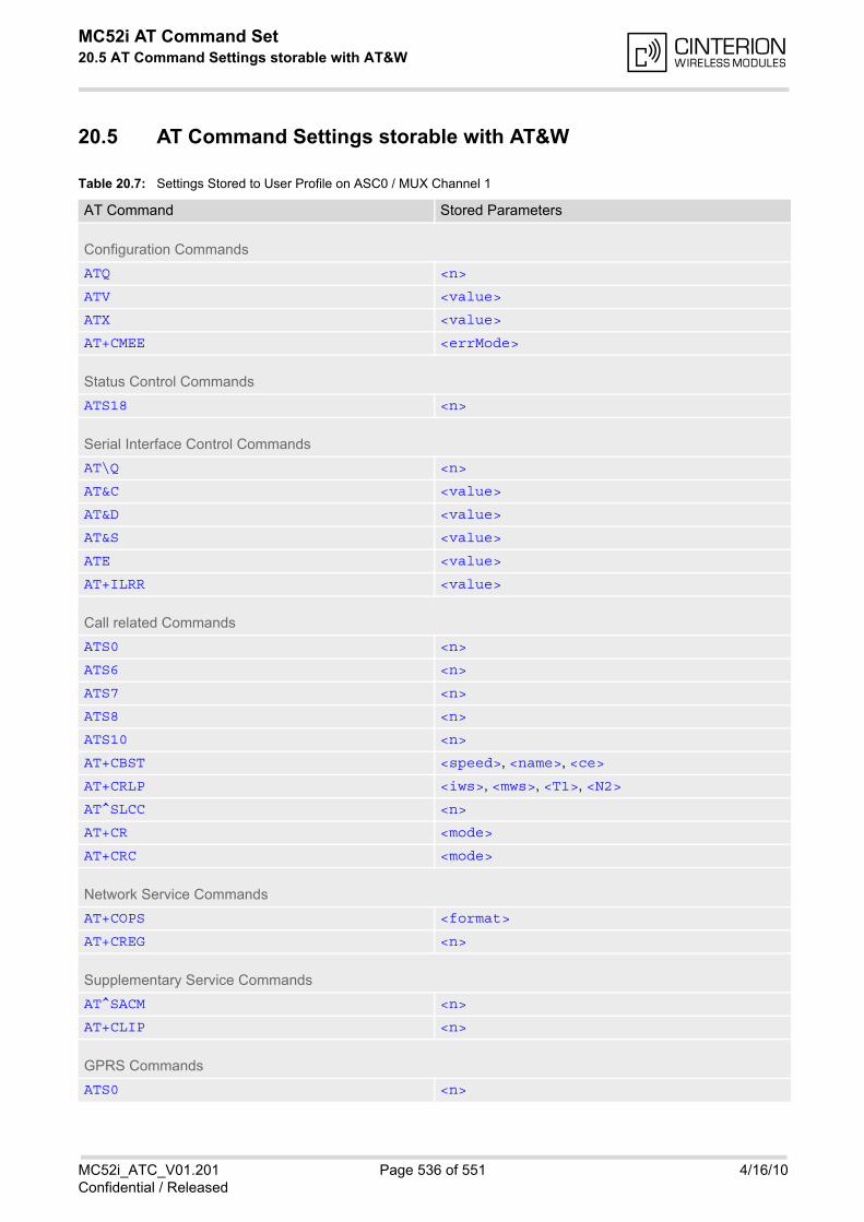
MC52i AT Command Set 20.5 AT Command Settings storable with AT&W
MC52i_ATC_V01.201 Page 536 of 551 4/16/10Confidential / Released
20.5 AT Command Settings storable with AT&W
Table 20.7: Settings Stored to User Profile on ASC0 / MUX Channel 1
AT Command Stored Parameters
Configuration Commands
ATQ <n>
ATV <value>
ATX <value>
AT+CMEE <errMode>
Status Control Commands
ATS18 <n>
Serial Interface Control Commands
AT\Q <n>
AT&C <value>
AT&D <value>
AT&S <value>
ATE <value>
AT+ILRR <value>
Call related Commands
ATS0 <n>
ATS6 <n>
ATS7 <n>
ATS8 <n>
ATS10 <n>
AT+CBST <speed>, <name>, <ce>
AT+CRLP <iws>, <mws>, <T1>, <N2>
AT^SLCC <n>
AT+CR <mode>
AT+CRC <mode>
Network Service Commands
AT+COPS <format>
AT+CREG <n>
Supplementary Service Commands
AT^SACM <n>
AT+CLIP <n>
GPRS Commands
ATS0 <n>
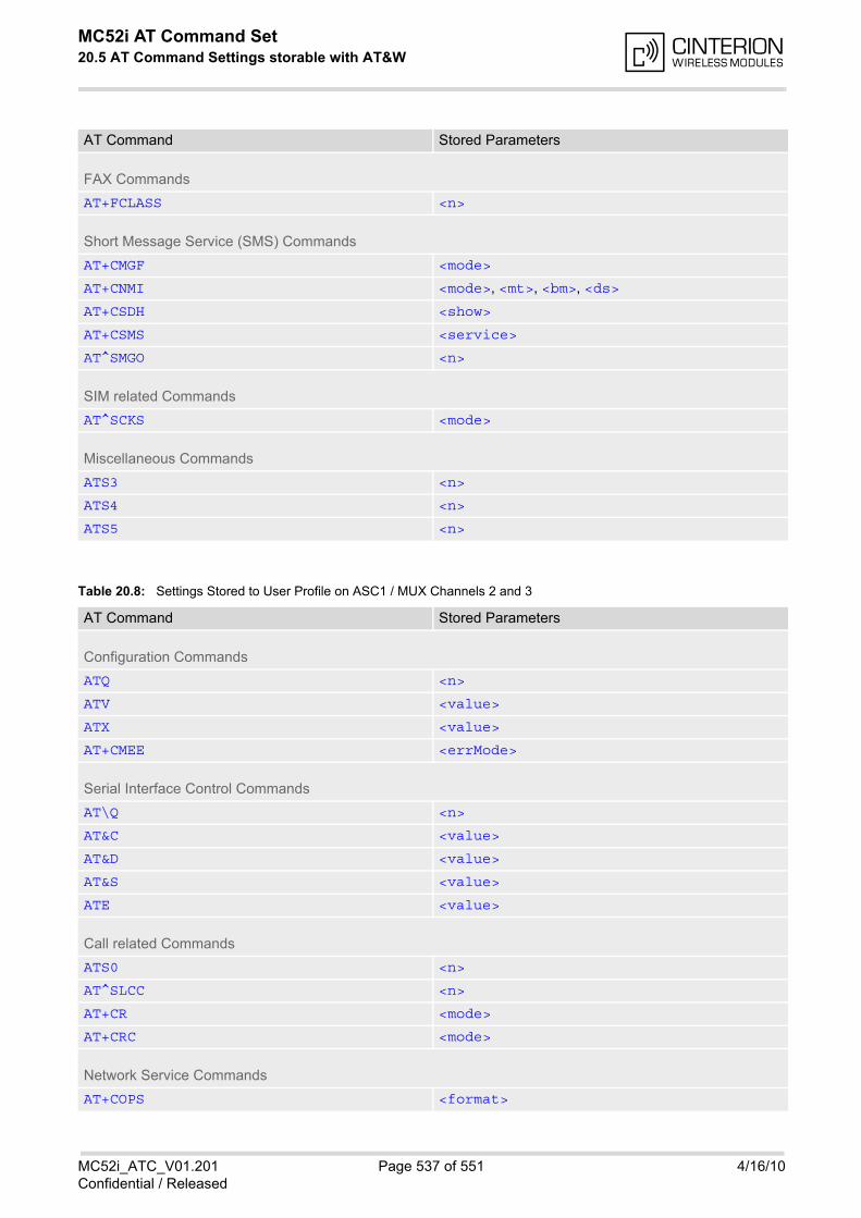
MC52i AT Command Set 20.5 AT Command Settings storable with AT&W
MC52i_ATC_V01.201 Page 537 of 551 4/16/10Confidential / Released
Table 20.8: Settings Stored to User Profile on ASC1 / MUX Channels 2 and 3
FAX Commands
AT+FCLASS <n>
Short Message Service (SMS) Commands
AT+CMGF <mode>
AT+CNMI <mode>, <mt>, <bm>, <ds>
AT+CSDH <show>
AT+CSMS <service>
AT^SMGO <n>
SIM related Commands
AT^SCKS <mode>
Miscellaneous Commands
ATS3 <n>
ATS4 <n>
ATS5 <n>
AT Command Stored Parameters
Configuration Commands
ATQ <n>
ATV <value>
ATX <value>
AT+CMEE <errMode>
Serial Interface Control Commands
AT\Q <n>
AT&C <value>
AT&D <value>
AT&S <value>
ATE <value>
Call related Commands
ATS0 <n>
AT^SLCC <n>
AT+CR <mode>
AT+CRC <mode>
Network Service Commands
AT+COPS <format>
AT Command Stored Parameters
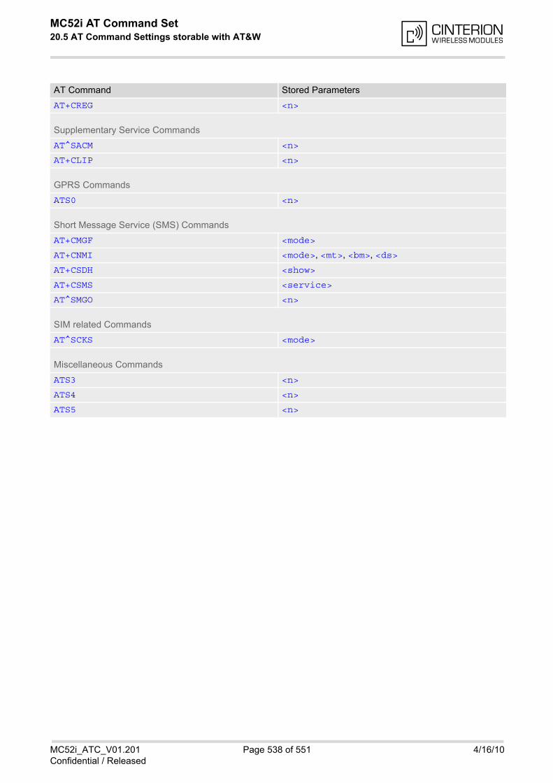
MC52i AT Command Set 20.5 AT Command Settings storable with AT&W
MC52i_ATC_V01.201 Page 538 of 551 4/16/10Confidential / Released
AT+CREG <n>
Supplementary Service Commands
AT^SACM <n>
AT+CLIP <n>
GPRS Commands
ATS0 <n>
Short Message Service (SMS) Commands
AT+CMGF <mode>
AT+CNMI <mode>, <mt>, <bm>, <ds>
AT+CSDH <show>
AT+CSMS <service>
AT^SMGO <n>
SIM related Commands
AT^SCKS <mode>
Miscellaneous Commands
ATS3 <n>
ATS4 <n>
ATS5 <n>
AT Command Stored Parameters
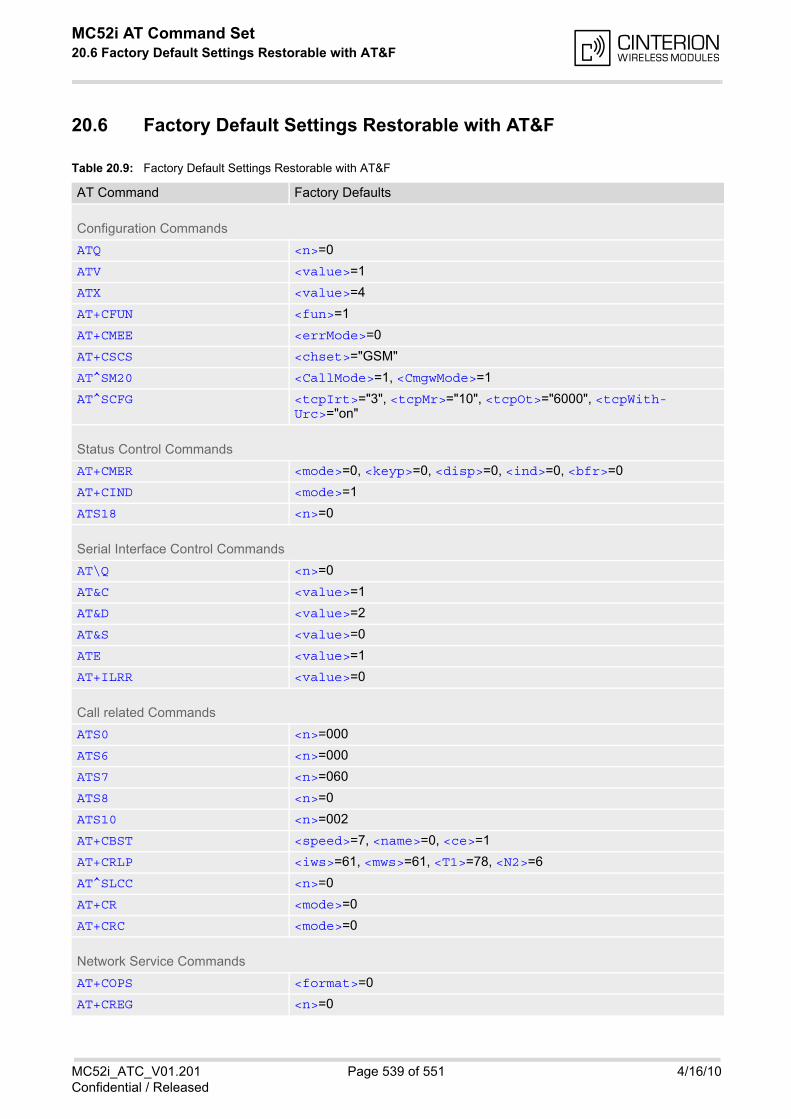
MC52i AT Command Set 20.6 Factory Default Settings Restorable with AT&F
MC52i_ATC_V01.201 Page 539 of 551 4/16/10Confidential / Released
20.6 Factory Default Settings Restorable with AT&F
Table 20.9: Factory Default Settings Restorable with AT&F
AT Command Factory Defaults
Configuration Commands
ATQ <n>=0
ATV <value>=1
ATX <value>=4
AT+CFUN <fun>=1
AT+CMEE <errMode>=0
AT+CSCS <chset>="GSM"
AT^SM20 <CallMode>=1, <CmgwMode>=1
AT^SCFG <tcpIrt>="3", <tcpMr>="10", <tcpOt>="6000", <tcpWith-Urc>="on"
Status Control Commands
AT+CMER <mode>=0, <keyp>=0, <disp>=0, <ind>=0, <bfr>=0
AT+CIND <mode>=1
ATS18 <n>=0
Serial Interface Control Commands
AT\Q <n>=0
AT&C <value>=1
AT&D <value>=2
AT&S <value>=0
ATE <value>=1
AT+ILRR <value>=0
Call related Commands
ATS0 <n>=000
ATS6 <n>=000
ATS7 <n>=060
ATS8 <n>=0
ATS10 <n>=002
AT+CBST <speed>=7, <name>=0, <ce>=1
AT+CRLP <iws>=61, <mws>=61, <T1>=78, <N2>=6
AT^SLCC <n>=0
AT+CR <mode>=0
AT+CRC <mode>=0
Network Service Commands
AT+COPS <format>=0
AT+CREG <n>=0
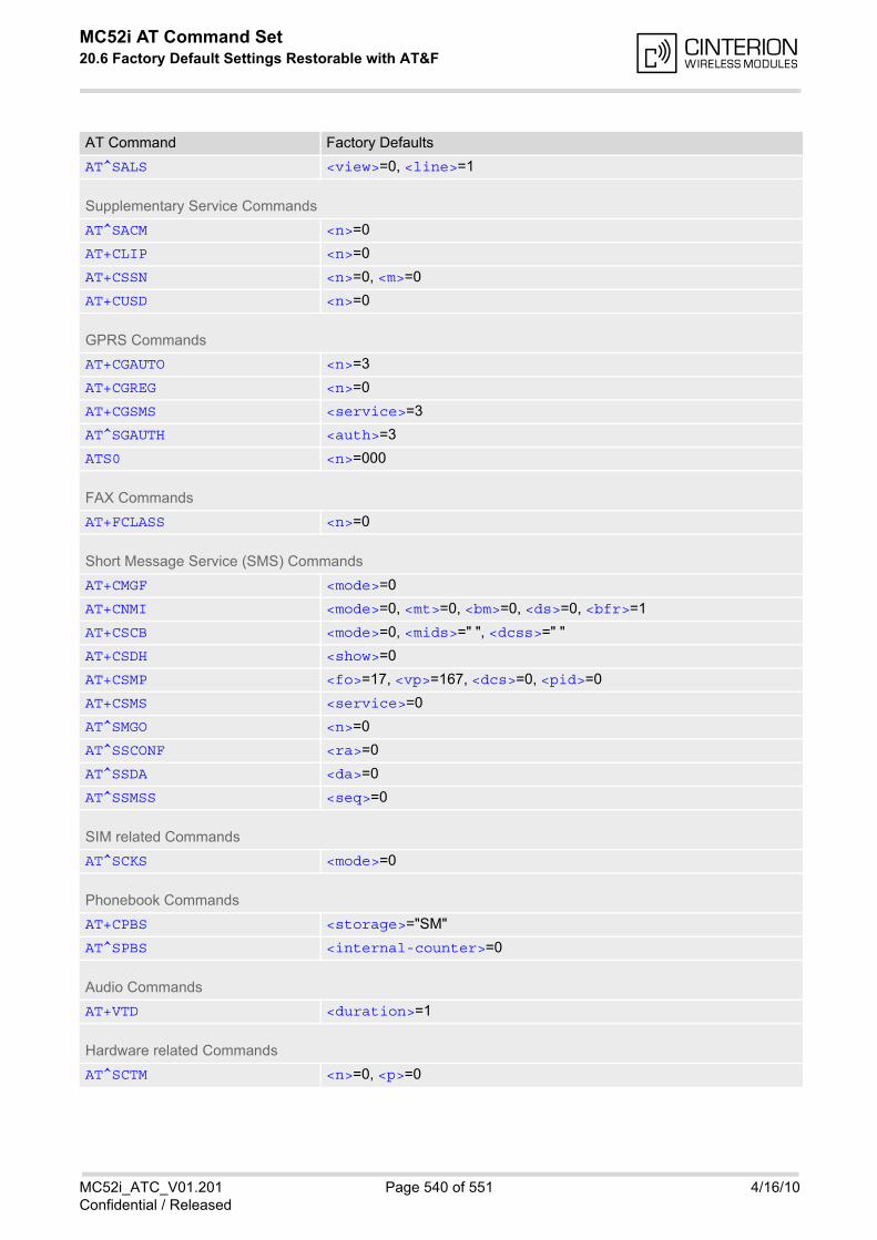
MC52i AT Command Set 20.6 Factory Default Settings Restorable with AT&F
MC52i_ATC_V01.201 Page 540 of 551 4/16/10Confidential / Released
AT^SALS <view>=0, <line>=1
Supplementary Service Commands
AT^SACM <n>=0
AT+CLIP <n>=0
AT+CSSN <n>=0, <m>=0
AT+CUSD <n>=0
GPRS Commands
AT+CGAUTO <n>=3
AT+CGREG <n>=0
AT+CGSMS <service>=3
AT^SGAUTH <auth>=3
ATS0 <n>=000
FAX Commands
AT+FCLASS <n>=0
Short Message Service (SMS) Commands
AT+CMGF <mode>=0
AT+CNMI <mode>=0, <mt>=0, <bm>=0, <ds>=0, <bfr>=1
AT+CSCB <mode>=0, <mids>=" ", <dcss>=" "
AT+CSDH <show>=0
AT+CSMP <fo>=17, <vp>=167, <dcs>=0, <pid>=0
AT+CSMS <service>=0
AT^SMGO <n>=0
AT^SSCONF <ra>=0
AT^SSDA <da>=0
AT^SSMSS <seq>=0
SIM related Commands
AT^SCKS <mode>=0
Phonebook Commands
AT+CPBS <storage>="SM"
AT^SPBS <internal-counter>=0
Audio Commands
AT+VTD <duration>=1
Hardware related Commands
AT^SCTM <n>=0, <p>=0
AT Command Factory Defaults

MC52i AT Command Set 20.6 Factory Default Settings Restorable with AT&F
MC52i_ATC_V01.201 Page 541 of 551 4/16/10Confidential / Released
Miscellaneous Commands
ATS3 <n>=013
ATS4 <n>=010
ATS5 <n>=008
AT Command Factory Defaults
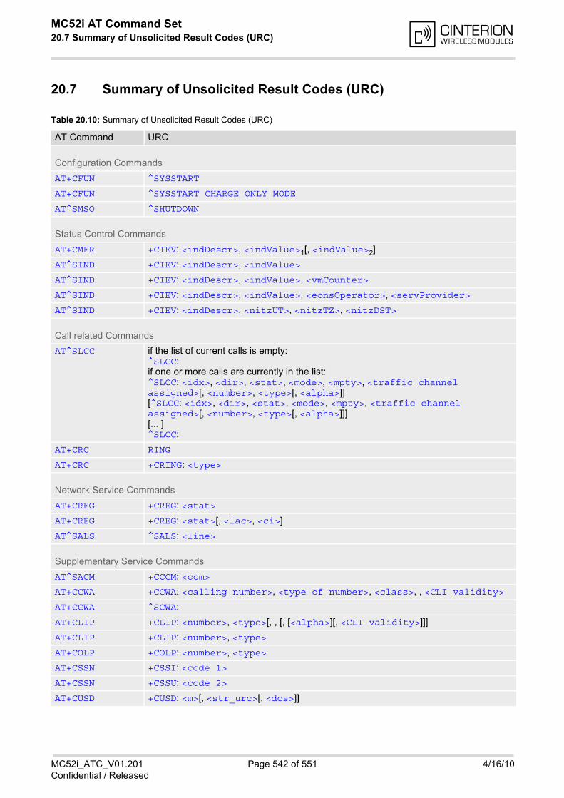
MC52i AT Command Set 20.7 Summary of Unsolicited Result Codes (URC)
MC52i_ATC_V01.201 Page 542 of 551 4/16/10Confidential / Released
20.7 Summary of Unsolicited Result Codes (URC)
Table 20.10: Summary of Unsolicited Result Codes (URC)
AT Command URC
Configuration Commands
AT+CFUN ^SYSSTART
AT+CFUN ^SYSSTART CHARGE ONLY MODE
AT^SMSO ^SHUTDOWN
Status Control Commands
AT+CMER +CIEV: <indDescr>, <indValue>1[, <indValue>2]
AT^SIND +CIEV: <indDescr>, <indValue>
AT^SIND +CIEV: <indDescr>, <indValue>, <vmCounter>
AT^SIND +CIEV: <indDescr>, <indValue>, <eonsOperator>, <servProvider>
AT^SIND +CIEV: <indDescr>, <nitzUT>, <nitzTZ>, <nitzDST>
Call related Commands
AT^SLCC if the list of current calls is empty: ^SLCC: if one or more calls are currently in the list: ^SLCC: <idx>, <dir>, <stat>, <mode>, <mpty>, <traffic channel assigned>[, <number>, <type>[, <alpha>]][^SLCC: <idx>, <dir>, <stat>, <mode>, <mpty>, <traffic channel assigned>[, <number>, <type>[, <alpha>]]][... ]^SLCC:
AT+CRC RING
AT+CRC +CRING: <type>
Network Service Commands
AT+CREG +CREG: <stat>
AT+CREG +CREG: <stat>[, <lac>, <ci>]
AT^SALS ^SALS: <line>
Supplementary Service Commands
AT^SACM +CCCM: <ccm>
AT+CCWA +CCWA: <calling number>, <type of number>, <class>, , <CLI validity>
AT+CCWA ^SCWA:
AT+CLIP +CLIP: <number>, <type>[, , [, [<alpha>][, <CLI validity>]]]
AT+CLIP +CLIP: <number>, <type>
AT+COLP +COLP: <number>, <type>
AT+CSSN +CSSI: <code 1>
AT+CSSN +CSSU: <code 2>
AT+CUSD +CUSD: <m>[, <str_urc>[, <dcs>]]

MC52i AT Command Set 20.7 Summary of Unsolicited Result Codes (URC)
MC52i_ATC_V01.201 Page 543 of 551 4/16/10Confidential / Released
Internet Service Commands
AT^SISR ^SISR: <srvProfileId>, <urcCauseId>
AT^SISW ^SISW: <srvProfileId>, <urcCauseId>
Internet Ser-vice URC "^SIS"
^SIS: <srvProfileId>, <urcCause>[, [<urcInfoId>][, <urcInfoText>]]
GPRS Commands
AT+CGEREP +CGEV: REJECT <PDP_type>, <PDP_addr>
AT+CGEREP +CGEV: NW REACT <PDP_type>, <PDP_addr>, [<cid>]
AT+CGEREP +CGEV: NW DEACT <PDP_type>, <PDP_addr>, [<cid>]
AT+CGEREP +CGEV: ME DEACT <PDP_type>, <PDP_addr>, [<cid>]
AT+CGEREP +CGEV: NW DETACH
AT+CGEREP +CGEV: ME DETACH
AT+CGEREP +CGEV: NW CLASS <class>
AT+CGEREP +CGEV: ME CLASS <class>
AT+CGREG +CGREG: <stat>
Short Message Service (SMS) Commands
AT+CNMI +CMTI: <mem3>, <index>
AT+CNMI +CMT: <length><CR><LF><pdu>
AT+CNMI +CMT: <oa>, <scts>[, <tooa>, <fo>, <pid>, <dcs>, <sca>, <tosca>, <length>]<CR><LF><data>
AT+CNMI +CBM: <length><CR><LF><pdu>
AT+CNMI +CBM: <sn>, <mid>, <dcs>, <page>, <pages><CR><LF><data>
AT+CNMI +CDS: <length><CR><LF><pdu>
AT+CNMI +CDS: <fo>, <mr>[, <ra>][, <tora>], <scts>, <dt>, <st>
AT+CNMI +CDSI: <mem3>, <index>
AT^SMGO ^SMGO: <mode>
SIM related Commands
AT^SCKS ^SCKS: <SimStatus>
SIM Application Toolkit (SAT) Commands
^SSTN ^SSTN: <cmdType>
^SSTN ^SSTN: <cmdTerminateValue>
^SSTN ^SSTN: 254
^SSTN ^SSTN: 255
Hardware related Commands
AT+CALA +CALA: [<text>]
AT+CALA ^SYSSTART ALARM MODE+CALA: <text>
AT^SBC ^SBC: Undervoltage
AT Command URC
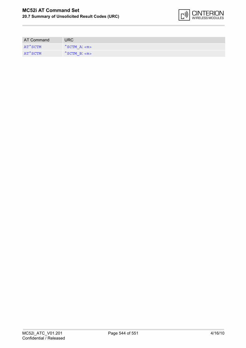
MC52i AT Command Set 20.7 Summary of Unsolicited Result Codes (URC)
MC52i_ATC_V01.201 Page 544 of 551 4/16/10Confidential / Released
AT^SCTM ^SCTM_A: <m>
AT^SCTM ^SCTM_B: <m>
AT Command URC
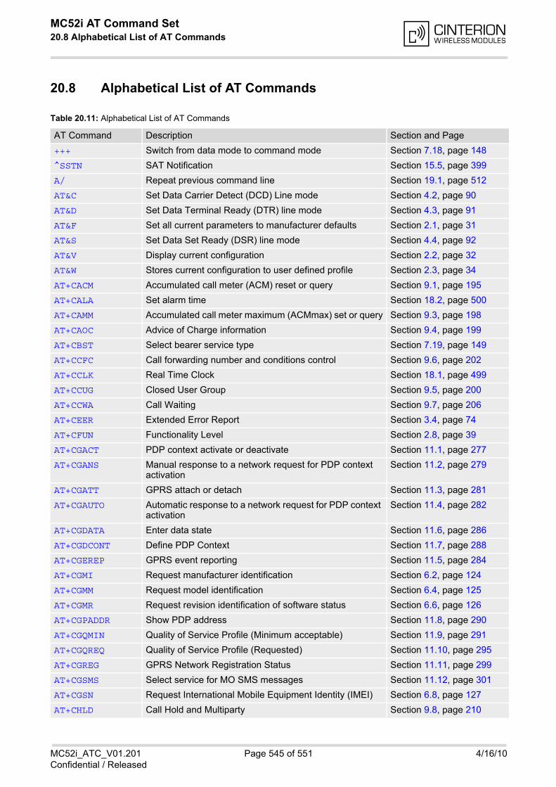
MC52i AT Command Set 20.8 Alphabetical List of AT Commands
MC52i_ATC_V01.201 Page 545 of 551 4/16/10Confidential / Released
20.8 Alphabetical List of AT Commands
Table 20.11: Alphabetical List of AT Commands
AT Command Description Section and Page
+++ Switch from data mode to command mode Section 7.18, page 148
^SSTN SAT Notification Section 15.5, page 399
A/ Repeat previous command line Section 19.1, page 512
AT&C Set Data Carrier Detect (DCD) Line mode Section 4.2, page 90
AT&D Set Data Terminal Ready (DTR) line mode Section 4.3, page 91
AT&F Set all current parameters to manufacturer defaults Section 2.1, page 31
AT&S Set Data Set Ready (DSR) line mode Section 4.4, page 92
AT&V Display current configuration Section 2.2, page 32
AT&W Stores current configuration to user defined profile Section 2.3, page 34
AT+CACM Accumulated call meter (ACM) reset or query Section 9.1, page 195
AT+CALA Set alarm time Section 18.2, page 500
AT+CAMM Accumulated call meter maximum (ACMmax) set or query Section 9.3, page 198
AT+CAOC Advice of Charge information Section 9.4, page 199
AT+CBST Select bearer service type Section 7.19, page 149
AT+CCFC Call forwarding number and conditions control Section 9.6, page 202
AT+CCLK Real Time Clock Section 18.1, page 499
AT+CCUG Closed User Group Section 9.5, page 200
AT+CCWA Call Waiting Section 9.7, page 206
AT+CEER Extended Error Report Section 3.4, page 74
AT+CFUN Functionality Level Section 2.8, page 39
AT+CGACT PDP context activate or deactivate Section 11.1, page 277
AT+CGANS Manual response to a network request for PDP context activation
Section 11.2, page 279
AT+CGATT GPRS attach or detach Section 11.3, page 281
AT+CGAUTO Automatic response to a network request for PDP context activation
Section 11.4, page 282
AT+CGDATA Enter data state Section 11.6, page 286
AT+CGDCONT Define PDP Context Section 11.7, page 288
AT+CGEREP GPRS event reporting Section 11.5, page 284
AT+CGMI Request manufacturer identification Section 6.2, page 124
AT+CGMM Request model identification Section 6.4, page 125
AT+CGMR Request revision identification of software status Section 6.6, page 126
AT+CGPADDR Show PDP address Section 11.8, page 290
AT+CGQMIN Quality of Service Profile (Minimum acceptable) Section 11.9, page 291
AT+CGQREQ Quality of Service Profile (Requested) Section 11.10, page 295
AT+CGREG GPRS Network Registration Status Section 11.11, page 299
AT+CGSMS Select service for MO SMS messages Section 11.12, page 301
AT+CGSN Request International Mobile Equipment Identity (IMEI) Section 6.8, page 127
AT+CHLD Call Hold and Multiparty Section 9.8, page 210
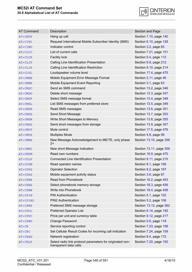
MC52i AT Command Set 20.8 Alphabetical List of AT Commands
MC52i_ATC_V01.201 Page 546 of 551 4/16/10Confidential / Released
AT+CHUP Hang up call Section 7.10, page 140
AT+CIMI Request International Mobile Subscriber Identity (IMSI) Section 6.10, page 128
AT+CIND Indicator control Section 3.2, page 65
AT+CLCC List of current calls Section 7.21, page 151
AT+CLCK Facility lock Section 5.4, page 112
AT+CLIP Calling Line Identification Presentation Section 9.9, page 212
AT+CLIR Calling Line Identification Restriction Section 9.10, page 214
AT+CLVL Loudspeaker volume level Section 17.4, page 475
AT+CMEE Mobile Equipment Error Message Format Section 2.11, page 46
AT+CMER Mobile Equipment Event Reporting Section 3.1, page 63
AT+CMGC Send an SMS command Section 13.2, page 346
AT+CMGD Delete short message Section 13.3, page 347
AT+CMGF Select SMS message format Section 13.4, page 348
AT+CMGL List SMS messages from preferred store Section 13.5, page 349
AT+CMGR Read SMS messages Section 13.6, page 351
AT+CMGS Send Short Message Section 13.7, page 353
AT+CMGW Write Short Messages to Memory Section 13.8, page 355
AT+CMSS Send short messages from storage Section 13.9, page 357
AT+CMUT Mute control Section 17.5, page 476
AT+CMUX Multiplex Mode Section 4.8, page 99
AT+CNMA New Message Acknowledgement to ME/TE, only phase 2+
Section 13.10, page 358
AT+CNMI New short Message Indication Section 13.11, page 359
AT+CNUM Read own numbers Section 16.9, page 470
AT+COLP Connected Line Identification Presentation Section 9.11, page 215
AT+COPN Read operator names Section 8.1, page 166
AT+COPS Operator Selection Section 8.2, page 167
AT+CPAS Mobile equipment activity status Section 3.6, page 87
AT+CPBR Read from Phonebook Section 16.2, page 453
AT+CPBS Select phonebook memory storage Section 16.3, page 456
AT+CPBW Write into Phonebook Section 16.4, page 458
AT+CPIN PIN Authentication Section 5.1, page 102
AT+CPIN2 PIN2 Authentication Section 5.2, page 106
AT+CPMS Preferred SMS message storage Section 13.12, page 362
AT+CPOL Preferred Operator List Section 8.14, page 192
AT+CPUC Price per unit and currency table Section 9.12, page 217
AT+CPWD Change Password Section 5.6, page 118
AT+CR Service reporting control Section 7.23, page 158
AT+CRC Set Cellular Result Codes for incoming call indication Section 7.24, page 159
AT+CREG Network registration Section 8.4, page 172
AT+CRLP Select radio link protocol parameters for originated non-transparent data calls
Section 7.20, page 150
AT Command Description Section and Page
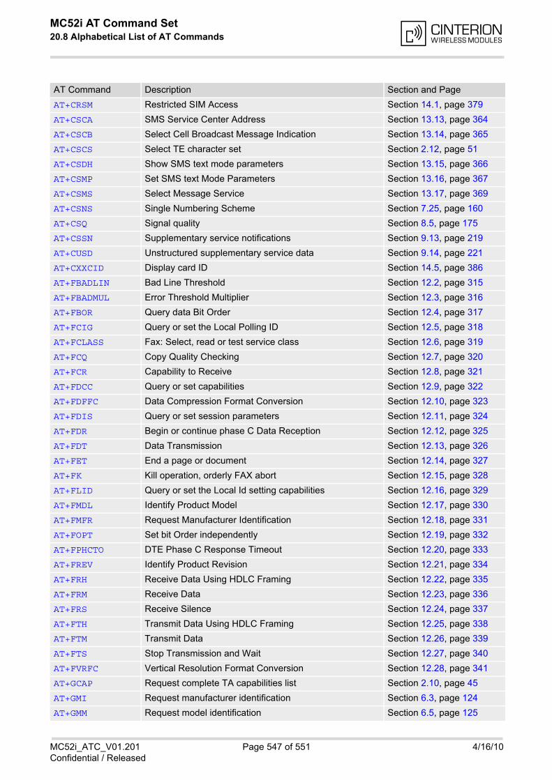
MC52i AT Command Set 20.8 Alphabetical List of AT Commands
MC52i_ATC_V01.201 Page 547 of 551 4/16/10Confidential / Released
AT+CRSM Restricted SIM Access Section 14.1, page 379
AT+CSCA SMS Service Center Address Section 13.13, page 364
AT+CSCB Select Cell Broadcast Message Indication Section 13.14, page 365
AT+CSCS Select TE character set Section 2.12, page 51
AT+CSDH Show SMS text mode parameters Section 13.15, page 366
AT+CSMP Set SMS text Mode Parameters Section 13.16, page 367
AT+CSMS Select Message Service Section 13.17, page 369
AT+CSNS Single Numbering Scheme Section 7.25, page 160
AT+CSQ Signal quality Section 8.5, page 175
AT+CSSN Supplementary service notifications Section 9.13, page 219
AT+CUSD Unstructured supplementary service data Section 9.14, page 221
AT+CXXCID Display card ID Section 14.5, page 386
AT+FBADLIN Bad Line Threshold Section 12.2, page 315
AT+FBADMUL Error Threshold Multiplier Section 12.3, page 316
AT+FBOR Query data Bit Order Section 12.4, page 317
AT+FCIG Query or set the Local Polling ID Section 12.5, page 318
AT+FCLASS Fax: Select, read or test service class Section 12.6, page 319
AT+FCQ Copy Quality Checking Section 12.7, page 320
AT+FCR Capability to Receive Section 12.8, page 321
AT+FDCC Query or set capabilities Section 12.9, page 322
AT+FDFFC Data Compression Format Conversion Section 12.10, page 323
AT+FDIS Query or set session parameters Section 12.11, page 324
AT+FDR Begin or continue phase C Data Reception Section 12.12, page 325
AT+FDT Data Transmission Section 12.13, page 326
AT+FET End a page or document Section 12.14, page 327
AT+FK Kill operation, orderly FAX abort Section 12.15, page 328
AT+FLID Query or set the Local Id setting capabilities Section 12.16, page 329
AT+FMDL Identify Product Model Section 12.17, page 330
AT+FMFR Request Manufacturer Identification Section 12.18, page 331
AT+FOPT Set bit Order independently Section 12.19, page 332
AT+FPHCTO DTE Phase C Response Timeout Section 12.20, page 333
AT+FREV Identify Product Revision Section 12.21, page 334
AT+FRH Receive Data Using HDLC Framing Section 12.22, page 335
AT+FRM Receive Data Section 12.23, page 336
AT+FRS Receive Silence Section 12.24, page 337
AT+FTH Transmit Data Using HDLC Framing Section 12.25, page 338
AT+FTM Transmit Data Section 12.26, page 339
AT+FTS Stop Transmission and Wait Section 12.27, page 340
AT+FVRFC Vertical Resolution Format Conversion Section 12.28, page 341
AT+GCAP Request complete TA capabilities list Section 2.10, page 45
AT+GMI Request manufacturer identification Section 6.3, page 124
AT+GMM Request model identification Section 6.5, page 125
AT Command Description Section and Page
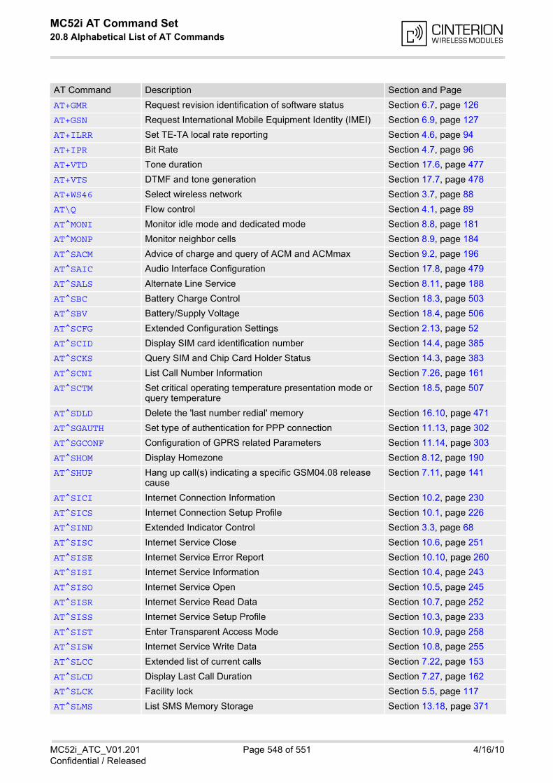
MC52i AT Command Set 20.8 Alphabetical List of AT Commands
MC52i_ATC_V01.201 Page 548 of 551 4/16/10Confidential / Released
AT+GMR Request revision identification of software status Section 6.7, page 126
AT+GSN Request International Mobile Equipment Identity (IMEI) Section 6.9, page 127
AT+ILRR Set TE-TA local rate reporting Section 4.6, page 94
AT+IPR Bit Rate Section 4.7, page 96
AT+VTD Tone duration Section 17.6, page 477
AT+VTS DTMF and tone generation Section 17.7, page 478
AT+WS46 Select wireless network Section 3.7, page 88
AT\Q Flow control Section 4.1, page 89
AT^MONI Monitor idle mode and dedicated mode Section 8.8, page 181
AT^MONP Monitor neighbor cells Section 8.9, page 184
AT^SACM Advice of charge and query of ACM and ACMmax Section 9.2, page 196
AT^SAIC Audio Interface Configuration Section 17.8, page 479
AT^SALS Alternate Line Service Section 8.11, page 188
AT^SBC Battery Charge Control Section 18.3, page 503
AT^SBV Battery/Supply Voltage Section 18.4, page 506
AT^SCFG Extended Configuration Settings Section 2.13, page 52
AT^SCID Display SIM card identification number Section 14.4, page 385
AT^SCKS Query SIM and Chip Card Holder Status Section 14.3, page 383
AT^SCNI List Call Number Information Section 7.26, page 161
AT^SCTM Set critical operating temperature presentation mode or query temperature
Section 18.5, page 507
AT^SDLD Delete the 'last number redial' memory Section 16.10, page 471
AT^SGAUTH Set type of authentication for PPP connection Section 11.13, page 302
AT^SGCONF Configuration of GPRS related Parameters Section 11.14, page 303
AT^SHOM Display Homezone Section 8.12, page 190
AT^SHUP Hang up call(s) indicating a specific GSM04.08 release cause
Section 7.11, page 141
AT^SICI Internet Connection Information Section 10.2, page 230
AT^SICS Internet Connection Setup Profile Section 10.1, page 226
AT^SIND Extended Indicator Control Section 3.3, page 68
AT^SISC Internet Service Close Section 10.6, page 251
AT^SISE Internet Service Error Report Section 10.10, page 260
AT^SISI Internet Service Information Section 10.4, page 243
AT^SISO Internet Service Open Section 10.5, page 245
AT^SISR Internet Service Read Data Section 10.7, page 252
AT^SISS Internet Service Setup Profile Section 10.3, page 233
AT^SIST Enter Transparent Access Mode Section 10.9, page 258
AT^SISW Internet Service Write Data Section 10.8, page 255
AT^SLCC Extended list of current calls Section 7.22, page 153
AT^SLCD Display Last Call Duration Section 7.27, page 162
AT^SLCK Facility lock Section 5.5, page 117
AT^SLMS List SMS Memory Storage Section 13.18, page 371
AT Command Description Section and Page
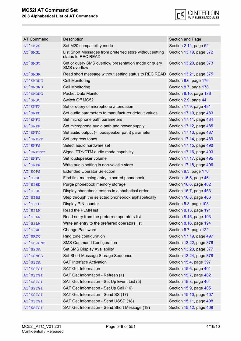
MC52i AT Command Set 20.8 Alphabetical List of AT Commands
MC52i_ATC_V01.201 Page 549 of 551 4/16/10Confidential / Released
AT^SM20 Set M20 compatibility mode Section 2.14, page 62
AT^SMGL List Short Messages from preferred store without setting status to REC READ
Section 13.19, page 372
AT^SMGO Set or query SMS overflow presentation mode or query SMS overflow
Section 13.20, page 373
AT^SMGR Read short message without setting status to REC READ Section 13.21, page 375
AT^SMONC Cell Monitoring Section 8.6, page 176
AT^SMOND Cell Monitoring Section 8.7, page 178
AT^SMONG Packet Data Monitor Section 8.10, page 186
AT^SMSO Switch Off MC52i Section 2.9, page 44
AT^SNFA Set or query of microphone attenuation Section 17.9, page 481
AT^SNFD Set audio parameters to manufacturer default values Section 17.10, page 483
AT^SNFI Set microphone path parameters Section 17.11, page 484
AT^SNFM Set microphone audio path and power supply Section 17.12, page 485
AT^SNFO Set audio output (= loudspeaker path) parameter Section 17.13, page 487
AT^SNFPT Set progress tones Section 17.14, page 489
AT^SNFS Select audio hardware set Section 17.15, page 490
AT^SNFTTY Signal TTY/CTM audio mode capability Section 17.16, page 493
AT^SNFV Set loudspeaker volume Section 17.17, page 495
AT^SNFW Write audio setting in non-volatile store Section 17.18, page 496
AT^SOPS Extended Operator Selection Section 8.3, page 170
AT^SPBC Find first matching entry in sorted phonebook Section 16.5, page 461
AT^SPBD Purge phonebook memory storage Section 16.6, page 462
AT^SPBG Display phonebook entries in alphabetical order Section 16.7, page 463
AT^SPBS Step through the selected phonebook alphabetically Section 16.8, page 466
AT^SPIC Display PIN counter Section 5.3, page 108
AT^SPLM Read the PLMN list Section 8.13, page 191
AT^SPLR Read entry from the preferred operators list Section 8.15, page 193
AT^SPLW Write an entry to the preferred operators list Section 8.16, page 194
AT^SPWD Change Password Section 5.7, page 122
AT^SRTC Ring tone configuration Section 17.19, page 497
AT^SSCONF SMS Command Configuration Section 13.22, page 376
AT^SSDA Set SMS Display Availability Section 13.23, page 377
AT^SSMSS Set Short Message Storage Sequence Section 13.24, page 378
AT^SSTA SAT Interface Activation Section 15.4, page 397
AT^SSTGI SAT Get Information Section 15.6, page 401
AT^SSTGI SAT Get Information - Refresh (1) Section 15.7, page 402
AT^SSTGI SAT Get Information - Set Up Event List (5) Section 15.8, page 404
AT^SSTGI SAT Get Information - Set Up Call (16) Section 15.9, page 405
AT^SSTGI SAT Get Information - Send SS (17) Section 15.10, page 407
AT^SSTGI SAT Get Information - Send USSD (18) Section 15.11, page 408
AT^SSTGI SAT Get Information - Send Short Message (19) Section 15.12, page 409
AT Command Description Section and Page

MC52i AT Command Set 20.8 Alphabetical List of AT Commands
MC52i_ATC_V01.201 Page 550 of 551 4/16/10Confidential / Released
AT^SSTGI SAT Get Information - Send DTMF (20) Section 15.13, page 410
AT^SSTGI SAT Get Information - Launch Browser (21) Section 15.14, page 411
AT^SSTGI SAT Get Information - Play Tone (32) Section 15.15, page 413
AT^SSTGI SAT Get Information - Display Text (33) Section 15.16, page 415
AT^SSTGI SAT Get Information - Get Inkey (34) Section 15.17, page 417
AT^SSTGI SAT Get Information - Get Input (35) Section 15.18, page 419
AT^SSTGI SAT Get Information - Select Item (36) Section 15.19, page 421
AT^SSTGI SAT Get Information - Set up Menu (37) Section 15.20, page 423
AT^SSTGI SAT Get Information - Set up Idle Mode Text (40) Section 15.21, page 425
AT^SSTR SAT Response Section 15.22, page 426
AT^SSTR SAT Response - Refresh (1) Section 15.23, page 427
AT^SSTR SAT Response - Set Up Event List (5) Section 15.24, page 428
AT^SSTR SAT Response - Set Up Call (16) Section 15.25, page 429
AT^SSTR SAT Response - Send SS (17) Section 15.26, page 430
AT^SSTR SAT Response - Send USSD (18) Section 15.27, page 431
AT^SSTR SAT Response - Send Short Message (19) Section 15.28, page 432
AT^SSTR SAT Response - Send DTMF (20) Section 15.29, page 433
AT^SSTR SAT Response - Launch Browser (21) Section 15.30, page 434
AT^SSTR SAT Response - Play Tone (32) Section 15.31, page 435
AT^SSTR SAT Response - Display Text (33) Section 15.32, page 436
AT^SSTR SAT Response - Get Inkey (34) Section 15.33, page 437
AT^SSTR SAT Response - Get Input (35) Section 15.34, page 439
AT^SSTR SAT Response - Select Item (36) Section 15.35, page 440
AT^SSTR SAT Response - Setup Menu (37) Section 15.36, page 441
AT^SSTR SAT Response - Set Up Idle Mode Text (40) Section 15.37, page 442
AT^SSTR SAT Event - Menu Selection (211) Section 15.38, page 443
AT^SSTR SAT Event - User Activity (232) Section 15.39, page 444
AT^SSTR SAT Event - Idle Screen Available (233) Section 15.40, page 445
AT^SSTR SAT Event - Language Selection (235) Section 15.41, page 446
AT^SSTR SAT Event - Browser Termination (236) Section 15.42, page 447
AT^SSTR SAT Event - Terminate Command (254) Section 15.43, page 448
AT^SSYNC Configure SYNC Pin Section 18.6, page 510
AT^STCD Display Total Call Duration Section 7.28, page 163
AT^SXSM Extended SIM Access Section 14.2, page 381
ATA Answer a call Section 7.2, page 130
ATA Manual response to a network request for PDP context activation
Section 11.15, page 304
ATD Mobile originated call to specified number Section 7.3, page 131
ATD*98# Request GPRS IP service Section 11.17, page 306
ATD*99# Request GPRS service Section 11.16, page 305
ATD><mem><n> Mobile originated call using specific memory and index number
Section 7.4, page 133
AT Command Description Section and Page
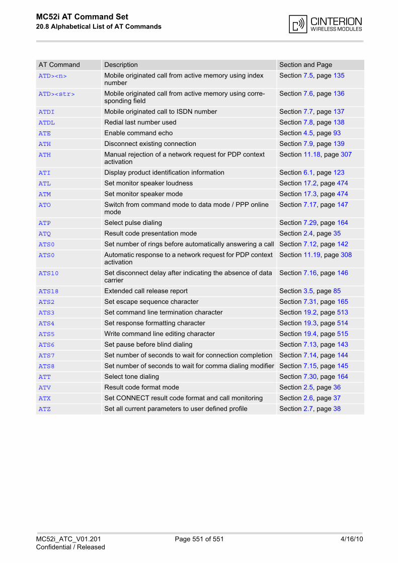
MC52i AT Command Set 20.8 Alphabetical List of AT Commands
MC52i_ATC_V01.201 Page 551 of 551 4/16/10Confidential / Released
ATD><n> Mobile originated call from active memory using index number
Section 7.5, page 135
ATD><str> Mobile originated call from active memory using corre-sponding field
Section 7.6, page 136
ATDI Mobile originated call to ISDN number Section 7.7, page 137
ATDL Redial last number used Section 7.8, page 138
ATE Enable command echo Section 4.5, page 93
ATH Disconnect existing connection Section 7.9, page 139
ATH Manual rejection of a network request for PDP context activation
Section 11.18, page 307
ATI Display product identification information Section 6.1, page 123
ATL Set monitor speaker loudness Section 17.2, page 474
ATM Set monitor speaker mode Section 17.3, page 474
ATO Switch from command mode to data mode / PPP online mode
Section 7.17, page 147
ATP Select pulse dialing Section 7.29, page 164
ATQ Result code presentation mode Section 2.4, page 35
ATS0 Set number of rings before automatically answering a call Section 7.12, page 142
ATS0 Automatic response to a network request for PDP context activation
Section 11.19, page 308
ATS10 Set disconnect delay after indicating the absence of data carrier
Section 7.16, page 146
ATS18 Extended call release report Section 3.5, page 85
ATS2 Set escape sequence character Section 7.31, page 165
ATS3 Set command line termination character Section 19.2, page 513
ATS4 Set response formatting character Section 19.3, page 514
ATS5 Write command line editing character Section 19.4, page 515
ATS6 Set pause before blind dialing Section 7.13, page 143
ATS7 Set number of seconds to wait for connection completion Section 7.14, page 144
ATS8 Set number of seconds to wait for comma dialing modifier Section 7.15, page 145
ATT Select tone dialing Section 7.30, page 164
ATV Result code format mode Section 2.5, page 36
ATX Set CONNECT result code format and call monitoring Section 2.6, page 37
ATZ Set all current parameters to user defined profile Section 2.7, page 38
AT Command Description Section and Page