Embed Size (px)
Citation preview

613-001527 Rev. B
AT-MC102XLPCIAT-MC102XLPCIe100TX to 100FX(SC) PCI & PCI Express Bus Media Converter
Installation Guide

Copyright © 2014 Allied Telesis, Inc.
All rights reserved. No part of this publication may be reproduced without prior written permission from Allied Telesis, Inc.
Allied Telesis and the Allied Telesis logo are trademarks of Allied Telesis, Incorporated. All other product names, company names, logos or other designations mentioned herein are trademarks or registered trademarks of their respective owners.
Allied Telesis, Inc. reserves the right to make changes in specifications and other information contained in this document without prior written notice. The information provided herein is subject to change without notice. In no event shall Allied Telesis, Inc. be liable for any incidental, special, indirect, or consequential damages whatsoever, including but not limited to lost profits, arising out of or related to this manual or the information contained herein, even if Allied Telesis, Inc. has been advised of, known, or should have known, the possibility of such damages.

Electrical Safety and Emissions Standards
This product meets the following standards.
RFI EmissionsFCC Class B, CISPR 22 Class B, EN55022 Class B, VCCI Class B, C-TICK
ImmunityEN55024
Electrical SafetyUL 60950-1 (CULUS), EN60950 (TUV), CSA, NRTL, CE
U.S. Federal Communications Commission
Declaration of Conformity
Manufacturer Name: Allied Telesis, Inc.
Declares that the product: Media Converter
Model Numbers: AT-MC102XLPCI, AT-MC102XLPCIe
This product complies with FCC Part 15B, Class B Limits:
This device complies with part 15 of the FCC Rules. Operation is subject to the following two conditions: (1) This device must not cause harmful interference, and (2) this device must accept any interference received, including interference that may cause undesired operation.
Radiated Energy
Note: This equipment has been tested and found to comply with the limits for a Class B digital device pursuant to Part 15 of FCC Rules. These limits are designed to provide reasonable protection against harmful interference in a residential installation. This equipment generates, uses and can radiate radio frequency energy and, if not installed and used in accordance with instructions, may cause harmful interference to radio or television reception, which can be determined by turning the equipment off and on. The user is encouraged to try to correct the interference by one or more of the following measures:
- Reorient or relocate the receiving antenna.
- Increase the separation between the equipment and the receiver.
- Connect the equipment into an outlet on a circuit different from that to which the receiver is connected.
- Consult the dealer or an experienced radio/TV technician for help.
Changes and modifications not expressly approved by the manufacturer or registrant of this equipment can void your authority to operate this equipment under Federal Communications Commission rules.
Industry Canada
This Class B digital apparatus meets all requirements of the Canadian Interference-Causing Equipment Regulations.
Cet appareil numérique de la classe B respecte toutes les exigences du Règlement sur le matériel brouilleur du Canada.
3

Translated Safety Statements
Important: The indicates that a translation of the safety statement is available in a PDF document titled “Translated Safety Statements” posted on the Allied Telesis website at www.alliedtelesis.com/support.
4
Contents
Preface ............................................................................................................................................................ 11Safety Symbols .......................................................................................................................................... 12Contacting Allied Telesis............................................................................................................................ 13
Chapter 1: Product Overview ....................................................................................................................... 15Key Features.............................................................................................................................................. 16Status LEDs ............................................................................................................................................... 17Auto MDI/MDIX .......................................................................................................................................... 18Auto-Negotiation ........................................................................................................................................ 19MissingLink & Link Test Features .............................................................................................................. 21
MissingLink Feature ............................................................................................................................ 21Link Test Feature................................................................................................................................. 21Configuring MissingLink & Link Test Features .................................................................................... 22
Chapter 2: Installation ................................................................................................................................... 23Reviewing Safety Precautions ................................................................................................................... 24Pre-Installation Checklist............................................................................................................................ 26
Planning the Installation ...................................................................................................................... 26Unpacking the Media Converter .......................................................................................................... 26Replacing the Bracket ......................................................................................................................... 28Configuring Auto-Negotiation .............................................................................................................. 29Configuring MissingLink & Link Test ................................................................................................... 30
Installing a Network Media Converter ........................................................................................................ 31Connecting the Network Cables................................................................................................................. 34
Chapter 3: Troubleshooting ......................................................................................................................... 37Twisted-Pair LED ....................................................................................................................................... 38Fiber Port LED ........................................................................................................................................... 39Link Test..................................................................................................................................................... 40
Technical Specifications ............................................................................................................................... 41
5

Contents
6

Figures
Figure 1. AT-MC102XLPCI Media Converter ..................................................................................................................... 16Figure 2. Status LEDs ........................................................................................................................................................ 17Figure 3. PC Board Location of Jumper J4......................................................................................................................... 19Figure 4. PC Board Location of Jumper J5......................................................................................................................... 22Figure 5. AT-MC102XLPCI Media Converter Items ........................................................................................................... 27Figure 6. Removing the Low-Profile Bracket ...................................................................................................................... 28Figure 7. Installing the Standard Bracket............................................................................................................................ 29Figure 8. Removing the PC Cover...................................................................................................................................... 31Figure 9. Removing the Faceplate From PCI Slot .............................................................................................................. 32Figure 10. Inserting the Adapter with a High-profile Bracket .............................................................................................. 32Figure 11. Securing the Adapter with a High-profile Bracket.............................................................................................. 33Figure 12. Connecting the Fiber Optic Cable to the AT-MC102XLPCI Media Converter ................................................... 34Figure 13. Connecting the Twisted-pair Cable to the AT-MC102XLPCI Media Converter ................................................. 35Figure 14. RJ-45 Connector and Port Pin Layout............................................................................................................... 43
7

List of Figures
8

Tables
9
Table 1. LED Functions ......................................................................................................................................................17Table 2. Auto-Negotiation Configuration- Jumper J4 Positions ..........................................................................................20Table 3. MissingLink & Link Test - Jumper J5 Positions ....................................................................................................22Table 4. Physical Specifications .........................................................................................................................................41Table 5. Operating and Storage Conditions .......................................................................................................................41Table 6. Electrical Rating ....................................................................................................................................................42Table 7. Agency Certifications ............................................................................................................................................42Table 8. Environmental Compliance ...................................................................................................................................42Table 9. Twisted-Pair Cable Requirements for the 100Base-TX Ports ..............................................................................43Table 10. RJ-45 Pin Signals for MDI and MDI-X ................................................................................................................43Table 11. Fiber Optic Cable Loss Budget ...........................................................................................................................44Table 12. Fiber Optic Launch Power ..................................................................................................................................44Table 13. Fiber Optic Receive Power .................................................................................................................................44Table 14. Fiber Optic Cable Distance .................................................................................................................................45Table 15. Fiber Optic Loss Specifications ..........................................................................................................................45

Tables
10

Preface
This guide contains instructions on how to install an AT-MC102XLPCI & AT-MC102XLPCIe 100Mbps Media Converters.
This preface contains the following sections:
❒ “Safety Symbols” on page 12
❒ “Contacting Allied Telesis” on page 13
11

Preface
Safety Symbols
This document uses the following conventions:
NoteNotes provide additional information.
CautionCautions inform you that performing or omitting a specific action may result in equipment damage or loss of data.
WarningWarnings inform you that performing or omitting a specific action may result in bodily injury.
WarningWarnings inform you that an eye and skin hazard exists due to the presence of a Class 1 laser device.
12

AT-MC102XLPCI & AT-MC102XLPCIE 100Mbps Media Converter Installation Guide
Contacting Allied Telesis
If you need assistance with this product, you may contact Allied Telesis technical support by going to the Support & Services section of the Allied Telesis web site at www.alliedtelesis.com/support. You can find links for the following services on this page:
❒ 24/7 Online Support - Enter our interactive support center to search for answers to your questions in our knowledge database, check support tickets, learn about RMAs, and contact Allied Telesis technical experts.
❒ USA and EMEA phone support - Select the phone number that best fits your location and customer type.
❒ Hardware warranty information - Learn about Allied Telesis warranties and register your product online.
❒ Replacement Services - Submit a Return Merchandise Authorization (RMA) request via our interactive support center.
❒ Documentation - View the most recent installation guides, user guides, software release notes, white papers and data sheets for your product.
❒ Software Updates - Download the latest software releases for your product.
For sales or corporate contact information, go to www.alliedtelesis.com/purchase and select your region.
13

Preface
14

Chapter 1
Product Overview
The AT-MC102XLPCI & AT-MC102XLPCIe 100Mbps Media Converters products are designed to connect with the PCI bus in a computer. The MC102XLPCI is designed for a PCI card slot and the MC102XLPCIe is designed to interface with a PCI Express card slot. The specifications for these two products along with their respective installation instructions are identical with one exception - the physical connector is different between the two products to conform with the different dimensions of the PCI and PCI Express connectors.
NoteFor simplicity in the rest of this manual, the AT-MC102XLPCI & AT-MC102XLPCIe 100Mbps Media Converters will be referred to as AT-MC102XLPCI Media Converter.
The AT-MC102XLPCI Media Converter is designed to connect a copper Ethernet medium with a fiber Ethernet medium. A common application for this product is providing an interconnection between a computer's network copper port and a fiber network infrastructure.
This chapter contains the following sections:
❒ Key Features on page 16
❒ Status LEDs on page 17
❒ Auto MDI/MDIX on page 18
❒ Auto-Negotiation on page 19
❒ MissingLink & Link Test Features on page 21
15

Chapter 1: Product Overview
Key Features
The AT-MC102XLPCI Media Converter features a 100Base-TX twisted-pair port and an 100Base-FX fiber optic port. The twisted-pair port has an RJ-45 connector and a maximum operating distance of 100 meters (328 feet). The fiber optic port has a dual SC connector and a maximum operating distance of 2 kilometers (1.2 miles).
This media converter operates at 100 Mbps and is configured from the factory for Auto-Negotiation mode.
The AT-MC102XLPCI Media Converter is designed to be installed in a PCI bus slot of a PC and does not require any software configuration or management.
An AT-MC102XLPCI Media Converter is illustrated in Figure 1.
Figure 1. AT-MC102XLPCI Media Converter
The AT-MC102XLPCI Media Converter has the following key features:
❒ 100Base-TX twisted-pair port Half- or full-duplex operation - See Figure 1.
❒ 100Base-FX fiber optic port - See Figure 1.
❒ See Status LEDs on page 17 for more information.
❒ See Auto MDI/MDIX on page 18 for more information.
❒ See Auto-Negotiation on page 19 for more information.
❒ See MissingLink & Link Test Features on page 21 for more information.
16

AT-MC102XLPCI & AT-MC102XLPCIE 100Mbps Media Converter Installation Guide
Status LEDs
The AT-MC102XLPCI Media Converter has two status LEDs associated with the 100Base-TX twisted-pair port and the 100Base-FX fiber optic port. The location of these LEDs is shown in Figure 2.
Figure 2. Status LEDs
The functional description of the port Status LEDs are given in Table 1.
Table 1. LED Functions
LED Color Description
TX
Solid Green1,2
1. In Link Test mode, the TX and RX link LEDs indicate link independently of each other based on whether their respective port has a compatible link.
Indicates a link is established on the copper port.
OFF Indicates that a link is not established on the copper port.
FX
Solid Green1,2
2. In Missing Link mode, the TX and FX LEDs will not indicate a link (OFF) until both ports are simultaneously linked successfully (Solid Green).
Indicates a link is established on the fiber port.
OFF Indicates that a link is not established on the fiber port.
Fiber Link
TXLink
LED LED
17

Chapter 1: Product Overview
Auto MDI/MDIX
An RJ-45 twisted-pair port on an 100 Mbps Ethernet network device can have one of two possible wiring configurations: MDI or MDI-X. The RJ-45 port on a PC, router, or bridge is typically wired as MDI, while the twisted-pair port on a switch or hub is usually MDI-X.
The AT-MC102XLPCI Media Converter features automatic MDI/MDI-X. The 100Base-TX port automatically determines the configuration of the port on the device to which it is connected and then configures itself appropriately. For example, if a port on a media converter is connected to a PC, which is typically wired as MDI, the port on the media converter automatically configures itself as MDI-X. This feature allows you to use a straight-through cable when connecting to any type of device.
18

AT-MC102XLPCI & AT-MC102XLPCIE 100Mbps Media Converter Installation Guide
Auto-Negotiation
The Auto-Negotiation feature is used to automatically determine a common duplex mode between the twisted-pair port and its link partner. This feature is enabled at the factory and is compatible with the IEEE 802.3u specification.
The 100FX port usually operates in Full Duplex mode. The goal of the Auto-Negotiation feature is to avoid a duplex mismatch between the copper and fiber ports of the AT-MC102XLPCI by ensuring that the twisted-pair port and its link partner are also configured to operate in Full Duplex mode. In most configurations, the link partner of the twisted-pair port is configured for Auto-Negotiation by default so the Auto-Negotiation feature of the MC102XLPCI also needs to also be activated (factory default configuration). If the twisted-pair link partner’s port is set to Fixed Full Duplex mode, then the MC102XLPCI should be configured with the Auto-Negotiation disabled. In both cases, these settings allow the twisted-pair ports to operate in Full Duplex mode.
NoteIf the twisted-pair link partner’s port is set to Fixed Half Duplex mode, a duplex mismatch can occur with the fiber port assuming the fiber port is operating in Full Duplex mode. This situation can result in significant degradation of Ethernet traffic throughput. To avoid this issue, ensure that the twisted-pair link partner’s port is configured for either Auto-Negotiation or Fixed Full Duplex when the fiber port is operating in Full Duplex mode.
The location of the jumper (J4) is shown in Figure 3. The Auto-Negotiation configuration and jumper pin positions for jumper J4 are given in Table 2.
Figure 3. PC Board Location of Jumper J4
19

Chapter 1: Product Overview
NoteAlthough it is not marked on J4, Pin 2 is positioned between pins 1 and 3.
NoteIf you choose to remove the jumper, Allied Telesis recommends that you re-install the jumper on the center pin (2) only, 90 degrees from the pins 1 and 3 so that it does not get lost.
Table 2. Auto-Negotiation Configuration- Jumper J4 Positions
Pin Position of Jumper Feature Configuration
1 and 2 (Factory Default) Auto-Negotiation feature enabled
2 and 3 Auto-Negotiation feature disabled
No Jumper Installed Auto-Negotiation feature enabled
20
AT-MC102XLPCI & AT-MC102XLPCIE 100Mbps Media Converter Installation Guide
MissingLink & Link Test Features
The MissingLink & Link Test jumper (J5) on the PC board is configured at the factory with the MissingLink feature enabled and Link Test disabled. This section contains the following topics:
❒ MissingLink Feature
❒ Link Test Feature
❒ Configuring MissingLink & Link Test Features on page 22
MissingLinkFeature
The MissingLink feature enables the fiber optic and twisted-pair ports on the media converter to pass the “Link” status of their connections to each other. The AT-MC102XLPCI is configured for MissingLink at the factory with pin 1 and pin 2 connected of jumper J5 (see Figure 4). When the AT-MC102XLPCI detects that an active link has gone down on one of its ports, it shuts down the link to its opposite port. The result is that the AT-MC102XLPCI notifies the end node connected to the opposite port by setting its link to go down.
This type of behavior is a form of network monitoring and fault notification for the network device connected to the opposite port of the AT-MC102XLPCI. Some network devices can be configured to recognize that the loss of connection on a port and take a specific action in response to this event. For example if the end node is a managed switch, it can be configured to choose a redundant path as an alternative data path and/or send out a trap to a network management station so that the network administrator can be notified of the problem.
For example, if the twisted-pair cable to the 100Base-TX port on the media converter were to fail and the link went down, the AT-MC102XLPCI would respond by dropping the link on the 100Base-FX fiber optic port. In this way, the media converter notifies the end-node connected to the fiber optic port that the connection on the twisted-pair port has been lost. If the failure had started with the fiber optic cabling, the unit would drop the link to the twisted-pair port. When the failed Ethernet path is repaired and the link is re-established, then the AT-MC102XLPCI re-establishes the link on its opposite port.
Link Test Feature The Link Test mode provides a method of testing the connections between the ports on the media converter and the nodes that are connected to the ports. If a network problem occurs, you can perform a Link Test to determine which port is experiencing a problem. This test allows you to focus on the port and end-node where the problem resides.
21
Chapter 1: Product Overview
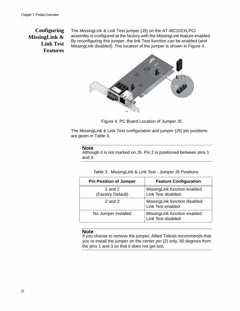
ConfiguringMissingLink &
Link TestFeatures
The MissingLink & Link Test jumper (J5) on the AT-MC102XLPCI assembly is configured at the factory with the MissingLink feature enabled. By reconfiguring this jumper, the link Test function can be enabled (and MissingLink disabled). The location of the jumper is shown in Figure 4.
Figure 4. PC Board Location of Jumper J5
The MissingLink & Link Test configuration and jumper (J5) pin positions are given in Table 3.
NoteAlthough it is not marked on J5, Pin 2 is positioned between pins 1 and 3.
NoteIf you choose to remove the jumper, Allied Telesis recommends that you re-install the jumper on the center pin (2) only, 90 degrees from the pins 1 and 3 so that it does not get lost.
Table 3. MissingLink & Link Test - Jumper J5 Positions
Pin Position of Jumper Feature Configuration
1 and 2(Factory Default)
MissingLink function enabledLink Test disabled
2 and 3 MissingLink function disabledLink Test enabled
No Jumper Installed MissingLink function enabledLink Test disabled
22
Chapter 2
Installation
This chapter contains the following installation procedures for the AT-MC102XLPCI Media Converter.
❒ "Reviewing Safety Precautions" on page 24
❒ "Planning the Installation" on page 26
❒ "Unpacking the Media Converter" on page 26
❒ "Pre-Installation Checklist" on page 26
❒ "Installing a Network Media Converter" on page 31
❒ "Connecting the Network Cables" on page 34
23

Chapter 2: Installation
Reviewing Safety Precautions
Please review the following safety guidelines before installing the media converter.
NoteThe indicates that a translation of the safety statement is available in a PDF document titled Translated Safety Statements.
WarningClass 1 Laser product. L1
WarningDo not stare into the laser beam. L2
WarningDo not look directly at the fiber optic cable ends or inspect the cable ends with an optical lens. L6
WarningDo not work on equipment or cables during periods of lightning activity. E2
Operating Temperature. This product is designed for a maximum ambient temperature of 40° degrees C. E7
All Countries: Install product in accordance with local and National Electrical Codes. E8
24

AT-MC102XLPCI & AT-MC102XLPCIE 100Mbps Media Converter Installation Guide
WarningThe adapter is being installed in a system that operates with voltages that can be lethal. Before you remove the cover of your system, you must observe the following precautions to protect yourself and to prevent damage to the system components:
– Remove any metallic objects or jewelry from your hands and wrists.
– Use only insulated and nonconducting tools.
– Verify that the system is powered off and unplugged before accessing the internal components.
– Installation or removal of adapters must be performed in a static-free environment. The use of a properly grounded wrist strap or other personal anti-static device and an anti-static mat is strongly recommended. E39
25

Chapter 2: Installation
Pre-Installation Checklist
This is a pre-installation checklist for you to follow prior to installing the AT-MC102XLPCI media converter in your computer chassis:
❒ Planning the Installation
❒ Unpacking the Media Converter
❒ "Replacing the Bracket" on page 28
❒ "Configuring Auto-Negotiation" on page 29
❒ "Configuring MissingLink & Link Test" on page 30
Planning theInstallation
Observe the following guidelines when planning the installation of your media converter:
❒ The end-node connected to the fiber port of the media converter must be configured for 100 Mbps Full Duplex. The end-node connected to the copper port of the media converter must be configured for either Auto-Negotiation or 100Mbps Full duplex which is configured with Jumper J4. See Table 2, “Auto-Negotiation Configuration- Jumper J4 Positions” on page 20 for more information.
❒ If you choose to disable the Auto-Negotiation feature, this must be done prior to installing the AT-MC102XLPCI into the computer chassis. See "Configuring Auto-Negotiation" on page 29 for more information.
❒ If you choose to disable the MissingLink feature and enable the Link Test feature, this must be done prior to installing the AT-MC102XLPCI into the computer chassis. See "Configuring MissingLink & Link Test" on page 30 and "Link Test" on page 40 for more information.
❒ Refer to Table 9, “Twisted-Pair Cable Requirements for the 100Base-TX Ports” on page 43 for the twisted-pair specifications.
❒ Refer to Table 12, “Fiber Optic Launch Power” on page 44 for the fiber optic port specifications.
Unpacking theMedia Converter
To unpack the AT-MC102XLPCI Media Converter, perform the following procedure:
26

AT-MC102XLPCI & AT-MC102XLPCIE 100Mbps Media Converter Installation Guide
WarningWear a grounding device and observe electrostatic discharge precautions when installing the network adapter card in a system. Failure to observe this caution could result in damage to the card.
1. Remove all components from the shipping package.
NoteStore the packaging material in a safe location. If you need to return the unit to Allied Telesis, you may re-use the packing material.
2. Make sure the following items are included in your package. If any item is missing or damaged, contact your Allied Telesis sales.
Figure 5. AT-MC102XLPCI Media Converter Items
3. Holding the AT-MC102XLPCI by the edges, remove it from its shipping package and place it on an anti-static surface.
4. Check the media converter for visible signs of damage, particularly on the card’s edge connector.
One AT-MC102XLPCI 100Mbps Media Converter with factory-installed low profile bracket
One standard profile PCI bracket
27

Chapter 2: Installation
CautionDo not attempt to install a damaged AT-MC102XLPCI media converter. If it is damaged, contact Allied Telesis.
Replacing theBracket
The AT-MC102XLPCI Media Converter is shipped with the low-profile bracket attached to the adapter and a separate standard-profile bracket. You may need to replace the low-profile bracket attached to your adapter with the standard profile bracket depending on your PC.
The following procedure describes how to remove the low-profile bracket from the adapter and replace it with the standard bracket. You can also use this procedure to remove the standard bracket and replace it with the low-profile bracket.
To replace the low-profile bracket with the standard bracket, perform the following procedure:
1. Remove the screws that attach the low-profile bracket to the adapter. See Figure 6.
Figure 6. Removing the Low-Profile Bracket
28

AT-MC102XLPCI & AT-MC102XLPCIE 100Mbps Media Converter Installation Guide
2. Align the tabs of the standard bracket with the holes on the adapter and fasten the screws onto the adapter. See Figure 7.
Figure 7. Installing the Standard Bracket
ConfiguringAuto-Negotiation
A jumper (J4) is pre-installed at the factory between pins 1 and 2 which enables the Auto-Negotiation feature. Refer to Figure 4 for the location of this jumper.
If you choose to move this jumper to reconfigure the Auto-Negotiation feature, it must be done prior to the installation of the AT-MC102XLPCI assembly into your computer chassis. Refer to Table 2 on page 20 for a functional description if this jumper (J4). To disable Auto-Negotiation, install jumper J4 between pins 2 and 3.
NoteIf this jumper (J4) is removed from the assembly, the Auto-Negotiation function is enabled.
NoteIf you choose to remove the jumper, Allied Telesis recommends that you re-install the jumper on the center pin (2) only, 90 degrees from the pins 1 and 3 so that it does not get lost.
29
Chapter 2: Installation
ConfiguringMissingLink &
Link Test
The MissingLink feature is enabled by default from the factory with a jumper (J5) pre-installed between pins 1 and 2 on the AT-MC102XLPCI assembly. Refer to Figure 4 for the location of this jumper.If you choose to disable MissingLink and enable Link Test, it must be done prior to the installation of the AT-MC102XLPCI assembly into your computer chassis. Refer to Table 3 on page 22 for a functional description of this jumper (J5). To disable MissingLink and enable Link Test, install jumper J5 between pins 2 and 3.
NoteIf this jumper (J5) is removed from the assembly, the MissingLink feature is enabled and Link Test is Disabled.
NoteIf you choose to remove the jumper, Allied Telesis recommends that you re-install the jumper on the center pin (2) only, 90 degrees from the pins 1 and 3 so that it does not get lost.
30

AT-MC102XLPCI & AT-MC102XLPCIE 100Mbps Media Converter Installation Guide
Installing a Network Media Converter
The following instructions apply to installing AT-MC102XLPCI Media Converter in most systems. For details about performing these tasks on your particular system, refer to the manuals that were supplied with your computer system.
NoteTo perform this procedure, you need to provide a Phillips-head screw driver.
To install an AT-MC102XLPCI Media Converter perform the following procedure:
1. Read the "Reviewing Safety Precautions" on page 24 and follow the "Pre-Installation Checklist" on page 26 before proceeding to the next step.
2. If your computer is powered on, turn off the power.
3. When the system is completely shut down, unplug your computer.
4. Ensure that proper electrical grounding procedures have been followed.
WarningHigh voltage inside the system presents a safety hazard. Make sure the power is off before removing the cover.
5. Remove the system cover. See Figure 8 .
Figure 8. Removing the PC Cover
31

Chapter 2: Installation
6. Depending on which product you are installing, select and empty non- shared PCI or PCIe slot on the computer motherboard.
7. Remove the faceplate that is associated with the card slot you have identified for installation. See Figure 9.
Figure 9. Removing the Faceplate From PCI Slot
NoteKeep the faceplate in a safe place. You may need it for future use.
8. On the inside of the computer chassis, push the media converter card until it is firmly seated in the appropriate PCI slot by applying even pressure at both corners of the card. See Figure 10. Make sure the card is securely seated.
Figure 10. Inserting the Adapter with a High-profile Bracket
32

AT-MC102XLPCI & AT-MC102XLPCIE 100Mbps Media Converter Installation Guide
CautionDo not use excessive force when seating the card, because this may damage the system or the adapter. If the card resists seating, remove it from the system, realign it, and try again.
9. Secure the network adapter card to the chassis with a Phillips-head screw (not provided). See Figure 11.
Figure 11. Securing the Adapter with a High-profile Bracket
10. Replace the system’s cover and secure it with the screws removed in Step 5.
11. Power the system on.
Once power is turned on to the computer system and it returns to proper operation, the AT-MC102XLPCI Media Converter is fully installed. Next, connect the network cables. See "Connecting the Network Cables" on page 34.
33
Chapter 2: Installation
Connecting the Network Cables
The AT-MC102XLPCI Media Converter has an SC type fiber optic connector with a transmit and receive ports and one twisted-pair connector.
For the fiber optic cable specifications, see Appendix A, “Fiber Optic Port Specifications” on page 43.
For twisted-pair cable specifications and pin-out information, see Appendix A, “RJ-45 Twisted-Pair Port Specifications” on page 43.
To connect a network cable to the adapter, perform the following procedure:
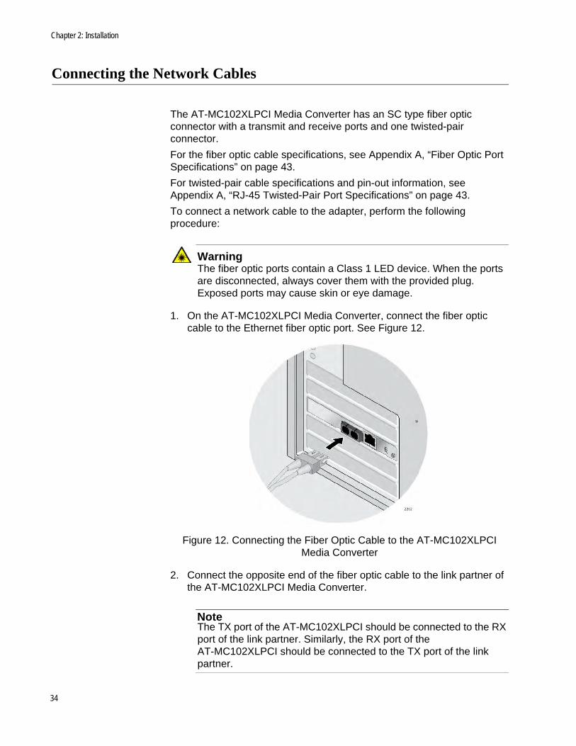
WarningThe fiber optic ports contain a Class 1 LED device. When the ports are disconnected, always cover them with the provided plug. Exposed ports may cause skin or eye damage.
1. On the AT-MC102XLPCI Media Converter, connect the fiber optic cable to the Ethernet fiber optic port. See Figure 12.
Figure 12. Connecting the Fiber Optic Cable to the AT-MC102XLPCI Media Converter
2. Connect the opposite end of the fiber optic cable to the link partner of the AT-MC102XLPCI Media Converter.
NoteThe TX port of the AT-MC102XLPCI should be connected to the RX port of the link partner. Similarly, the RX port of the AT-MC102XLPCI should be connected to the TX port of the link partner.
34

AT-MC102XLPCI & AT-MC102XLPCIE 100Mbps Media Converter Installation Guide
3. On the AT-MC102XLPCI Media Converter, connect the twisted-pair Ethernet cable to the RJ-45 port. See Figure 13.
Figure 13. Connecting the Twisted-pair Cable to the AT-MC102XLPCI Media Converter
4. Connect the other end of the twisted-pair cable to the link partner of the AT-MC102XLPCI Media Converter.
After you connect the system to the network and power is supplied, the AT-MC102XLPCI Media Converter attempts to establish a link at 100 Mbps.
NoteAfter the cables are properly connected at both ends and power is supplied to the devices at both ends of each cable, the media converter port LEDs should be functional. See "Status LEDs" on page 17 for a description of LED operation.
35

Chapter 2: Installation
36

Chapter 3
Troubleshooting
The following guidelines are provided to test and troubleshoot the installation in the event a problem occurs:
❒ Twisted-Pair LED
❒ Fiber Port LED on page 39
❒ Link Test on page 40
37

Overview
Twisted-Pair LED
If the LINK LED for the twisted-pair port is OFF, do the following:
1. Verify that the PC is powered ON and has booted up successfully.
2. Check that the end-node connected to the port is powered ON and is operating properly.
3. Check that the twisted-pair cable is securely connected to the twisted-pair port on the media converter and on the remote end-node.
4. Make sure that the twisted-pair cable does not exceed 100 meters (328 feet) and that you are using Category 5 or better Ethernet cable.
5. Verify that the copper port of the media converter and the copper end node are configured with matching speed/duplex settings (both set to Auto Negotiate OR both set to 100Mbps Full Duplex).
6. If you are still experiencing problems, refer to Contacting Allied Telesis on page 13 or visit our web site at www.alliedtelesis.com/support.
38

AT-MC102XLPCI & AT-MC102XLPCIE 100Mbps Media Converter Installation Guide
Fiber Port LED
If the LINK LED for the fiber optic port is OFF, do the following:
1. Verify that the PC is powered ON and has booted up successfully.
2. Verify that the end-node connected to the port is powered ON and is operating properly.
3. Check that the fiber optic cable is securely connected to the fiber optic port on the media converter and on the end-node.
4. Verify that the end node connected to the fiber port of the media converter is a 100FX port and that it is configured for 100 Mbps Full Duplex.
5. Make sure that the cable connected to the media converter’s receiver port (RX) is connected to the end-node’s transmitter port (TX) and that the media converter’s transmitter port (TX) is connected to the end-node’s receiver port (RX).
6. Test the attenuation on the fiber optic cable to ensure that it does not exceed acceptable values. Refer to Fiber Optic Port Specifications on page 43 for more information.
7. Verify that you are using the appropriate type of fiber optic cable and that you have not exceeded the maximum operating distance. For maximum operating distances and cable types, refer to Fiber Optic Port Specifications on page 43.
8. Check that the operating specifications (e.g., wavelength and maximum operating distance) of the fiber optic port on the end-node are compatible with the operating specifications of the fiber optic port on the media converter. Refer to Fiber Optic Port Specifications on page 43 for more information.
9. If you are still experiencing problems, refer to Contacting Allied Telesis on page 13 or visit our web site at www.alliedtelesis.com/support.
39
Overview
Link Test
To check hardware reliability of the media converter, perform the following procedure:
1. If the media converter is not already configured for Link Test mode, Power OFF the PC chassis where the media converter is installed and remove the the media converter from the chassis.
2. Configure the media converter for Link Test and re-install the media converter in the PC and then re-install the media converter in the PC chassis.
NoteSee Installing a Network Media Converter on page 31 for more information.
NoteSee Configuring MissingLink & Link Test on page 30 for more information.
3. Connect the RJ-45 twisted pair port to a 100Base port on an end-node, such as an Ethernet switch, and power ON the end-node.
4. Verify that the copper port of the media converter and the copper end node are configured with matching speed/duplex settings (both set to Auto Negotiate OR both set to 100Mbps Full Duplex).
5. Using a tested and good fiber patch cable, attach the fiber cable to the fiber connector of the media converter and the opposite end to a another Ethernet device with a compatible 100 MB fiber port. Power ON the end-node.
6. Power ON the PC chassis where the media converter is installed.
7. Verify that the PC is powered ON and has booted up successfully.
8. Verify that the LINK LED on both the twisted pair and fiber optic ports are green.
9. If the LEDs are green, the unit is working properly and there is a problem elsewhere on the segment.
10. If the LEDs are OFF, , refer to Contacting Allied Telesis on page 13 or visit our web site at www.alliedtelesis.com/support.
40

Appendix A
Technical Specifications
This appendix contains the following specifications
❒ Physical Specifications
❒ Operating and Storage Conditions
❒ Electrical Rating on page 42
❒ Agency Certifications on page 42
❒ Environmental Compliance on page 42
❒ RJ-45 Twisted-Pair Port Specifications on page 43
❒ Fiber Optic Port Specifications on page 43
Physical Specifications
Operating and Storage Conditions
Table 4. Physical Specifications
Dimensions (W x H) 12.5 cm x 6.4 cm (4.9 in x 2.5 in)
Weight .062 kg (2.2 oz)
Table 5. Operating and Storage Conditions
Operating Temperature
0° C to 40° C (32° F to 105° F)
Storage Temperature -20° C to 80° C (-4° F to 176° F)
Operating Humidity 5% to 90% non-condensing
Storage Humidity 5% to 95% non-condensing
Operating Altitude Up to 3,048 meters (10,000 feet)
41

Chapter : Technical Specifications
Electrical Rating
Agency Certifications
Environmental Compliance
Table 6. Electrical Rating
Input Supply Voltage 3.3 V DC
Power Consumption 1.65 Watts Maximum
Table 7. Agency Certifications
RFI Emissions FCC Part 15 Class B, EN55022 Class B, CISPR 22 Class B, C-TICK
Immunity EN55024
Electrical Safety UL 60950-1 (CULUS), EN60950-1 (TUV), CE
Laser Safety: EN60825-1
Table 8. Environmental Compliance
Eu-RoHS compliant Yes
China-RoHS compliant Yes
WEEE Yes
42

AT-MC102XLPCI & AT-MC102XLPCIE 100Mbps Media Converter Installation Guide
RJ-45 Twisted-Pair Port Specifications
This section contains the following RJ-45 twisted pair port specifications:
❒ Cable Requirements on page 43
❒ RJ-45 Twisted- Pair Port Pinouts on page 43
CableRequirements
The cable requirements of the RJ-45 twisted-pair port are given in Table 9.
RJ-45 Twisted-Pair Port Pinouts
Figure 14 illustrates the pin layout to an RJ-45 connector and port.
Figure 14. RJ-45 Connector and Port Pin Layout
Table 10 lists the MDI and MDI-X RJ-45 pin signals with a twisted-pair port.
Table 9. Twisted-Pair Cable Requirements for the 100Base-TX Ports
Cable Type 100Mbps
Standard TIA/EIA 568-A-compliant Category 5 or TIA/EIA 568-B-compliant Enhanced Category 5 (Cat 5e) shielded or unshielded cabling with 100 ohm impedance and a frequency of 100 MHz.
Yes
Standard TIA/EIA 568-B-compliant Category 6 or 6a shielded cabling.
Yes
Table 10. RJ-45 Pin Signals for MDI and MDI-X
Pin MDI Signal MDI-X Signal
1 TX+ RX+
2 TX- RX-
3 RX+ TX+
6 RX- TX-
43

Chapter : Technical Specifications
Fiber Optic Port Specifications
The cable requirements of the fiber port are given in Table 11.
The fiber optic specifications are given in the following tables:
❒ Table 12, “Fiber Optic Launch Power”
❒ Table 13, “Fiber Optic Receive Power”
❒ Table 14, “Fiber Optic Cable Distance” on page 45
❒ Table 15, “Fiber Optic Loss Specifications” on page 45
Table 11. Fiber Optic Cable Loss Budget
Type of Fiber Optic Cable
Maximum Operating Distance
Maximum Allowable Loss
Budget
50/125 or 62.5/125 micron multimode
2 km (1.2 mi) 13 dB at 1310 nm
Table 12. Fiber Optic Launch Power
Fiber Type
1
1. MMF = Multimode Fiber
Fiber Optic
Diameter (microns)
Optical Wavelength
Launch Power (dBm)2
2. The launch power is measured at one meter from the transmitter.
Min. Avg. Max.
MMF50/125
or62.5/125
1310 nm -19.0 -16.8 -14.0
Table 13. Fiber Optic Receive Power
Fiber Type
1
1. MMF = Multimode Fiber / SMF = Single-mode Fiber
Fiber Optic
Diameter (microns)
Optical Wavelength
Receive Power (dBm)
Min. Typical Saturation
MMF50/125
or 62.5/125
1310 nm -31.8 -34.5 -14.0
44

AT-MC102XLPCI & AT-MC102XLPCIE 100Mbps Media Converter Installation Guide
Table 14. Fiber Optic Cable Distance
Fiber Type1
1. MMF = Multimode Fiber / SMF = Single-mode Fiber
Max. Power /
Link Budget
Min. Distance Spec.2
2. The recommended minimum range is stated in all cases where the maximum transmitter output power exceeds the receivers saturation level. This is to prevent blinding or burning out of the optical receiver on the far-end-node.
Max. Distance Spec.
50/125 MMFor
62.5/125 MMF12.8 dB 0 2 km (1.2 mi)
Table 15. Fiber Optic Loss Specifications
Fiber Type1
1. MMF = Multimode Fiber
Fiber Optic Diameter (microns)
Optical Wavelength
Typical Loss Factor (dB/km)
Bandwidth (Mhz * km)
MMF50/125 1310 nm 1.00 400
62.5/125 1310 nm 1.00 500
45

Chapter : Technical Specifications
46