Embed Size (px)
Citation preview

GE Consumer & IndustrialPower Quality
ZTG SeriesLow-Voltage Automatic Transfer Switches

PB-1201 • Page 2
GE Zenith’s ZTG Series switches are built for standard applicationsrequiring the dependability and ease of operation found in a powercontactor switch.
• Ratings 40 to 3000 amps (2, 3 or 4 poles)
• UL 1008 listed at 480 VAC
• CSA certified at 600 VAC (200-260 amp - 480V)
• IEC listed at 480V
• Double throw, mechanically interlocked contactor mechanism
• Electrically operated, mechanically held
• Designed for emergency and standby applications
• Available in standard (ZTG) or delayed transition (ZTGD) models
ZTG switches are equipped with GE Zenith’s next-generation MX150microprocessor panel, which controls the operation and displays thestatus of the transfer switch’s position, timers and available sources. As an embedded digital controller, the MX150 offers high reliability and ease of unattended operation across a range of applications. The MX150 features include:
• Timer and voltage/frequency settings adjustable without disconnectionfrom the power section
• Built-in diagnostics with an LCD display for immediate troubleshooting
• LED/LCD indicators for ease of viewing and long life
• Nonvolatile memory—clock battery backup not required for standardswitch operation
• Processor and digital circuitry isolated from line voltage
• Inputs optoisolated for high electrical immunity to transients and noise
• Communications network interface
Fully Approved
• UL, CSA and IEC listed
• Ringing wave immunity per IEEE 472(ANSI C37.90A)
• Conducted and Radiated Emissions per EN55022 Class B (CISPR 22) (Exceeds EN55011 & MILSTD 461 Class 3)
• ESD immunity test per EN61000-4-2Class B (Level 4)
• Radiated RF, electromagnetic fieldimmunity test per EN61000-4-3(ENV50140) 10v/m
• Electrical fast transient/burst immunitytest per EN61000-4-4
• Surge immunity test per EN61000-4-5 IEEE C62.41 (1.2 X 50μs, 0.5 & 4 kV)
• Conducted immunity test perEN61000-4-6 (ENV50141)
• Voltage dips and interruption immunityEN61000-4-11
Design and Construction Features
• Close differential 3 phase under-voltagesensing of Source 1 (normal)—factorystandard setting 90% pickup, 80%dropout (adjustable); under-frequencysensing of Source 1 factory setting95% pickup (adjustable)
• Voltage and frequency sensing of theSource 2 (emergency)—factory standardsetting 90% pickup voltage, 95% pickupfrequency (adjustable)
• Test switch (fast test/load/no load) tosimulate Source 1 (normal) failure—automatically bypassed should theSource 2 (emergency) fail
• NEMA Type 1 enclosure is standard—also available in open style or NEMATypes 3R, 4, 4X or 12

Page 3 • PB-1201
Standard Features (MSTDG Option Pkg.)MX150 Control Panel
Front View
6/P Test Switch, Momentary
A3 Auxiliary Contact: Closed when the switch is in the Source 2 position (S2)
A4 Auxiliary Contact: Closed when the switch is in the Source 1 position (S1)
CALIBRATE Capabilities are available for Frequency and AB, BC, CA Phase to Phasevoltage for both Sources
CDT Daily 7, 14, 28 timed exercise (CDT memory backup battery included),pushbutton/timer operation
E Engine Start Contact
EL/P Event Log of 16 Events that track date, time, reason and action taken
J1E Adjustable under frequency sensor for S2
K/P Voltage and Frequency Indication for S1 and S2
L Indicating LED Pilot Lights:
L1 Indicates switch in S2 positionL2 Indicates switch in S1 positionL3 Indicates S1 source available L4 Indicates S2 source available
P1 Time Delay to Engine Start
Q2 Peak Shave / Remote Load Test
R50 In-Phase Monitor, self-adjusting
T Time Delay on Retransfer to Normal: To delay retransfer to S1 (immediate retransfer on S2 failure)
R2E Under voltage sensing of S2
S13 Microprocessor activated commit / no commit on tranferring to S2
U Time Delay for Engine Cool Down: Allows engine to run unloaded afterswitch retransfer to S1
W Time Delay on Transfer to Emergency: To delay transfer to S2 after availability
YEN Pushbutton Bypass of T & W Timers
When specified for use with a ZTGD Series delayed transition switch, the control panelalso includes the following:
DT Time Delay from Neutral Switch Position to S1 on Retransfer
DW Time Delay from Neutral Switch Position to S2
LN/P Center-Off position/Off Delay Timing indicating lights
MX150
S 1 O K * E *
2 1 : 5 6M O N 1 0 A P R 2 0 0 6
M O R E T E S T
Additional Standard Features (MEXEG Option Pkg.)
CDP Clock Exerciser Load/No Load (Replaces CDT Exerciser Option)
VI Voltage Imbalance Monitor (Three Phase)
PB-1201 • Page 4
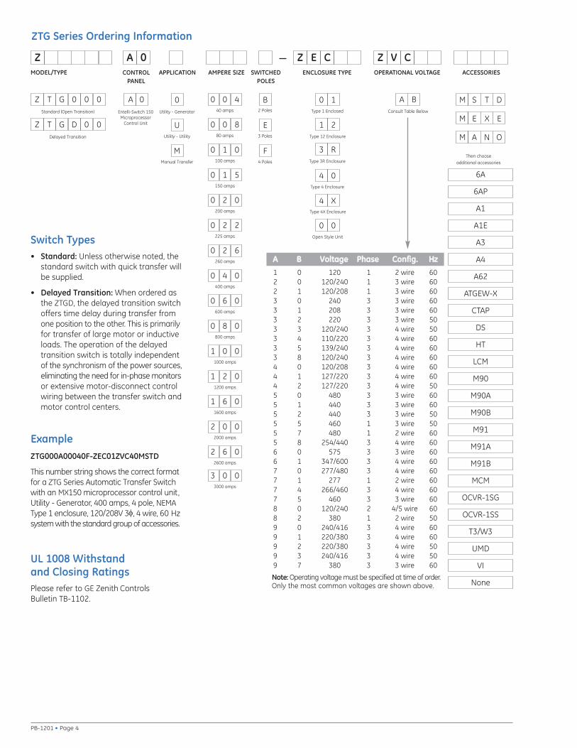
ExampleZTG000A00040F-ZEC01ZVC40MSTD
This number string shows the correct formatfor a ZTG Series Automatic Transfer Switchwith an MX150 microprocessor control unit,Utility - Generator, 400 amps, 4 pole, NEMAType 1 enclosure, 120/208V 3φ, 4 wire, 60 Hzsystem with the standard group of accessories.
Switch Types• Standard: Unless otherwise noted, the
standard switch with quick transfer willbe supplied.
• Delayed Transition: When ordered asthe ZTGD, the delayed transition switchoffers time delay during transfer fromone position to the other. This is primarilyfor transfer of large motor or inductiveloads. The operation of the delayedtransition switch is totally independentof the synchronism of the power sources,eliminating the need for in-phase monitorsor extensive motor-disconnect controlwiring between the transfer switch andmotor control centers.
6A
6AP
A1
A1E
A3
A4
A62
ATGEW-X
CTAP
DS
HT
LCM
M90
M90A
M90B
M91
M91A
M91B
MCM
OCVR-1SG
OCVR-1SS
T3/W3
UMD
VI
None
Then choose additional accessories
UL 1008 Withstand and Closing RatingsPlease refer to GE Zenith ControlsBulletin TB-1102.
MODEL/TYPE AMPERE SIZE SWITCHEDPOLES
ENCLOSURE TYPE OPERATIONAL VOLTAGE ACCESSORIES
A BConsult Table Below40 amps Type 1 Enclosed
Open Style Unit
B2 Poles
F4 Poles
E3 Poles
A 0Standard (Open Transition)
Z A 0 Z E C Z V C
T DSM
CONTROLPANEL
0 0 4
80 amps
0 0 8
100 amps
0 1 0
150 amps
0 1 5
200 amps
0 2 0
225 amps
0 2 2
260 amps
0 2 6
400 amps
0 4 0
600 amps
0 6 0
800 amps
0 8 0
1000 amps
1 0 0
1200 amps
1 2 0
1600 amps
1 6 0
2000 amps
2 0 0
2600 amps
2 6 0
3000 amps
3 0 0
APPLICATION
0Utility - Generator
MManual Transfer
UUtility - Utility
Type 4 Enclosure
Type 12 Enclosure
Type 4X Enclosure
Type 3R Enclosure
0 1
1 2
3 R
4 0
4 X
0 0
AA BB VVoollttaaggee PPhhaassee CCoonnffiigg.. HHzz1 0 120 1 2 wire 602 0 120/240 1 3 wire 602 1 120/208 1 3 wire 603 0 240 3 3 wire 603 1 208 3 3 wire 603 2 220 3 3 wire 503 3 120/240 3 4 wire 503 4 110/220 3 4 wire 603 5 139/240 3 4 wire 603 8 120/240 3 4 wire 604 0 120/208 3 4 wire 604 1 127/220 3 4 wire 604 2 127/220 3 4 wire 505 0 480 3 3 wire 605 1 440 3 3 wire 605 2 440 3 3 wire 505 5 460 1 3 wire 505 7 480 1 2 wire 605 8 254/440 3 4 wire 606 0 575 3 3 wire 606 1 347/600 3 4 wire 607 0 277/480 3 4 wire 607 1 277 1 2 wire 607 4 266/460 3 4 wire 607 5 460 3 3 wire 608 0 120/240 2 4/5 wire 608 2 380 1 2 wire 509 0 240/416 3 4 wire 609 1 220/380 3 4 wire 609 2 220/380 3 4 wire 509 3 240/416 3 4 wire 509 7 380 3 3 wire 60
Note: Operating voltage must be specified at time of order.Only the most common voltages are shown above.
X EEM
N OAM
ZTG Series Ordering Information
Entelli-Switch 150Microprocessor
Control Unit
Z T G 0 0 0
Delayed Transition
Z T G D 0 0
Page 5 • PB-1201
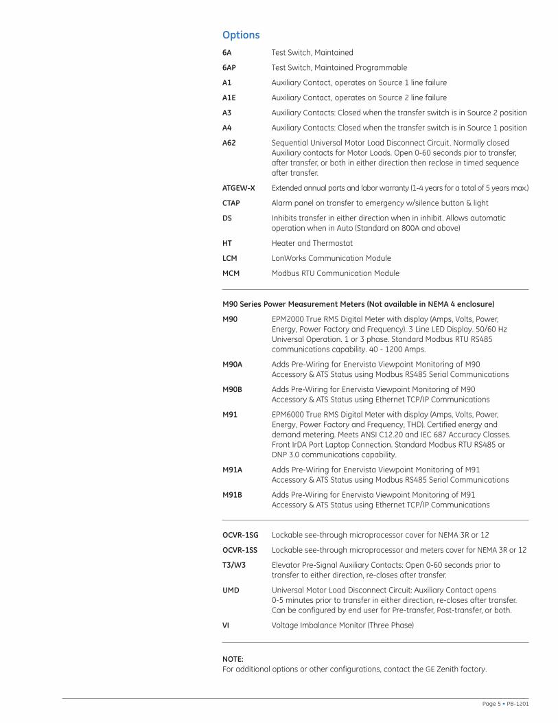
Options
NOTE:For additional options or other configurations, contact the GE Zenith factory.
6A Test Switch, Maintained
6AP Test Switch, Maintained Programmable
A1 Auxiliary Contact, operates on Source 1 line failure
A1E Auxiliary Contact, operates on Source 2 line failure
A3 Auxiliary Contacts: Closed when the transfer switch is in Source 2 position
A4 Auxiliary Contacts: Closed when the transfer switch is in Source 1 position
A62 Sequential Universal Motor Load Disconnect Circuit. Normally closedAuxiliary contacts for Motor Loads. Open 0-60 seconds pior to transfer,after transfer, or both in either direction then reclose in timed sequenceafter transfer.
ATGEW-X Extended annual parts and labor warranty (1-4 years for a total of 5 years max.)
CTAP Alarm panel on transfer to emergency w/silence button & light
DS Inhibits transfer in either direction when in inhibit. Allows automatic operation when in Auto (Standard on 800A and above)
HT Heater and Thermostat
LCM LonWorks Communication Module
MCM Modbus RTU Communication Module
M90 Series Power Measurement Meters (Not available in NEMA 4 enclosure)
M90 EPM2000 True RMS Digital Meter with display (Amps, Volts, Power, Energy, Power Factory and Frequency). 3 Line LED Display. 50/60 HzUniversal Operation. 1 or 3 phase. Standard Modbus RTU RS485 communications capability. 40 - 1200 Amps.
M90A Adds Pre-Wiring for Enervista Viewpoint Monitoring of M90 Accessory & ATS Status using Modbus RS485 Serial Communications
M90B Adds Pre-Wiring for Enervista Viewpoint Monitoring of M90 Accessory & ATS Status using Ethernet TCP/IP Communications
M91 EPM6000 True RMS Digital Meter with display (Amps, Volts, Power, Energy, Power Factory and Frequency, THD). Certified energy and demand metering. Meets ANSI C12.20 and IEC 687 Accuracy Classes.Front IrDA Port Laptop Connection. Standard Modbus RTU RS485 or DNP 3.0 communications capability.
M91A Adds Pre-Wiring for Enervista Viewpoint Monitoring of M91 Accessory & ATS Status using Modbus RS485 Serial Communications
M91B Adds Pre-Wiring for Enervista Viewpoint Monitoring of M91 Accessory & ATS Status using Ethernet TCP/IP Communications
OCVR-1SG Lockable see-through microprocessor cover for NEMA 3R or 12
OCVR-1SS Lockable see-through microprocessor and meters cover for NEMA 3R or 12
T3/W3 Elevator Pre-Signal Auxiliary Contacts: Open 0-60 seconds prior to transfer to either direction, re-closes after transfer.
UMD Universal Motor Load Disconnect Circuit: Auxiliary Contact opens 0-5 minutes prior to transfer in either direction, re-closes after transfer.Can be configured by end user for Pre-transfer, Post-transfer, or both.
VI Voltage Imbalance Monitor (Three Phase)
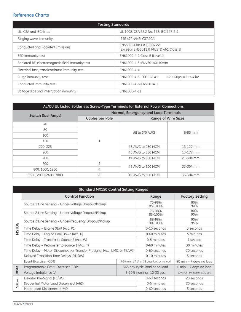
Reference Charts
PB-1201 • Page 6
Testing Standards
UL, CSA and IEC listed UL 1008, CSA 22.2 No. 178, IEC 947-6-1
Ringing wave immunity IEEE 472 (ANSI C37.90A)
ESD immunity test EN61000-4-2 Class B (Level 4)
Radiated RF, electromagnetic field immunity test EN61000-4-3 (ENV50140) 10v/m
Electrical fast, transient/burst immunity test EN61000-4-4
Conducted immunity test EN61000-4-6 (ENV50141)
Voltage dips and interruption immunity EN61000-4-11
Surge immunity test EN61000-4-5 IEEE C62.41 1.2 X 50μs, 0.5 to 4 kV
Conducted and Radiated EmissionsEN55022 Class B (CISPR 22) (Exceeds EN55011 & MILSTD 461 Class 3)
AL/CU UL Listed Solderless Screw-Type Terminals for External Power Connections
Switch Size (Amps)
40
80
100
150
400
600
800, 1000, 1200
2
4
Normal, Emergency and Load TerminalsCables per Pole
1
Range of Wire Sizes
#8 to 3/0 AWG
#6 AWG to 250 MCM
#4 AWG to 600 MCM
#2 AWG to 600 MCM
Source 1 Line Sensing – Under-voltage Dropout/Pickup
Source 2 Line Sensing – Under-voltage Dropout/Pickup
Source 2 Line Sensing – Under-frequency Dropout/Pickup
Time Delay – Engine Start (Acc. P1)
Time Delay – Engine Cool Down (Acc. U)
Time Delay – Transfer to Source 2 (Acc. W)
Time Delay – Retransfer to Source 1 (Acc. T)
75-98%85-100%75-98%
85-100%88-98%
90-100%
0-10 seconds
0-60 minutes
0-5 minutes
0-60 minutes
0-60 seconds
80%90%
Control Function Range Factory Setting
80%90%
90%95%
3 seconds
5 minutes
1 second
30 minutes
Time Delay – Motor Disconnect or Transfer Presignal (Acc. UMD, or T3/W3)
Delayed Transition Time Delays (DT, DW) 0-10 minutes
20 seconds
5 seconds
200, 225
1600, 2000, 2600, 3000 8 #2 AWG to 600 MCM
#6 AWG to 350 MCM
Elevator Pre-Signal (T3/W3)
0 min. - 7 days no load
10% Fail, 8% Restore; 30 sec.
20 seconds
20 seconds
5 seconds
MST
DG
8-85 mm
13-127 mm
13-177 mm
21-304 mm
33-304 mm
33-304 mm
Motor Load Disconnect (UMD)
Sequential Motor Load Disconnect (A62)
Opt
ions
260
365 day cycle, load or no load
0-60 seconds
0-5 minutes
0-60 seconds
5-20% nominal; 10-30 sec.
20 min. - 7 days no load5-60 min.-1,7,14 or 28 days load or no load
Voltage Imbalance (VI)
Programmable Event Exerciser (CDP)
MEX
EG
Event Exerciser (CDT)
Standard MX150 Control Setting Ranges

Page 7 • PB-1201
Dimensional and Weight Specifications
1. Metric dimensions (cm) and weights (kg) shown in parentheses adjacent to English measurements.
2. Includes 1.25" door projection beyond base depth. Allow a minimum of 3" additional depth for projection of handle, lights, switches, pushbuttons, etc.
3. All dimensions and weights are approximate and subject to change without notice.
4. Packing materials must be added to weights shown. Allow 15% additional weight for cartons, skids, crates, etc.
5. Special enclosure (NEMA 3R, 4, 4X, 12, etc.) dimensions and layouts may differ. Consult factory for details.
6. A ZTG(D) 40-225A, when ordered with the following options, will require a larger enclosure of 46”x 24”x 14.13” (HxWxD): A62(T), Digital Meter, HT, OCVR-1SG, OCVR-1SS.
7. Add 3" in height for removable lifting eyes.
8. Ventilation louvers on side and rear of enclosure at 1600-3000 amps. One set of louvers must be clear for airflow with standard cable connections.
Reference Figures
Figure A Figure B Figure C
Application Notes:
ZTG and ZTGD Model, Dimensions and Weight
Model AmpereRating Poles
NEMA 1 Weight ApplicationNotes
Height(A)
Width(B)
Depth(C)
Ref.Figure
OpenType NEMA 1
ZTG
40, 80 2, 3 24 (61) 18 (46) 11 (28) A 21 (10) 57 (26) 1 - 64 21 (10) 60 (27)
100, 150 2, 3 24 (61) 18 (46) 11 (28) A 21 (10) 57 (26) 1 - 64 21 (10) 60 (27)
200, 225 2, 3 24 (61) 18 (46) 11 (28) A 21 (10) 57 (26) 1 - 64 21 (10) 60 (27)
260, 400 2, 3 46 (117) 24 (61) 14 (36) A 70 (32) 175 (80) 1 - 54 75 (34) 180 (82)
600 2, 3 66 (168) 24 (61) 19.5 (50) B 165 (75) 400 (450) 1 - 5, 74 185 (84) 450 (204)
800, 1000, 1200 2, 3 74 (188) 40 (102) 19.5 (50) B 190 (86) 455 (206) 1 - 5, 74 210 (95) 540 (245)
1600, 2000 3 90 (229) 35.5 (90) 48 (122) C 345 (156) 1010 (458) 1 - 5, 7-84 450 (204) 1160 (526)
3000 3 90 (229) 35.5 (90) 48 (122) C 465 (211) 1010 (458) 1 - 5, 7-84 670 (304) 1160 (526)
ZTGD
40, 80 2, 3 46 (117) 24 (61) 14 (36) A 21 (10) 57 (26) 1 - 64 21 (10) 60 (27)
100, 150 2, 3 46 (117) 24 (61) 14 (36) A 21 (10) 57 (26) 1 - 64 21 (10) 60 (27)
200, 225 2, 3 46 (117) 24 (61) 14 (36) A 21 (10) 57 (26) 1 - 64 21 (10) 60 (27)
260, 400 2, 3 46 (117) 24 (61) 14 (36) A 80 (36) 220 (100) 1 - 54 85 (39) 230 (102)
600 2, 3 66 (168) 24 (61) 19.5 (50) B 185 (84) 400 (181) 1 - 5, 74 205 (93) 450 (204)
800, 1000, 1200 2, 3 74 (188) 40 (102) 19.5 (50) B 210 (95) 475 (215) 1 - 5, 74 230 (104) 560 (254)
1600, 2000 3 90 (229) 35.5 (90) 48 (122) C 365 (166) 1010 (458) 1 - 5, 7-84 470 (204) 1160 (526)
3000 3 90 (229) 35.5 (90) 48 (122) C 485 (220) 1130 (513) 1 - 5, 7-84 690 (313) 1395 (633)

PB-1201 (10/06)
GE Consumer & Industrial – Power Quality701 E 22nd Street, Lombard, IL 60148 USA
773 299 6600 www.geindustrial.com/ats
Information subject to change without notice. Please verify all details with GE. © 2006 General Electric Company All Rights Reserved
Extensive Customer Service and Support
Supported by a worldwide network of factory-trained AuthorizedService Centers, our Technical Service Representatives can provide you with field service, equipment parts and preventive maintenance.
Because emergency power systems are required to operate under themost adverse circumstances, site personnel may be called upon at anytime to make decisions regarding the operation of the system, thereforetraining of these personnel is critical to the future of any installation.
GE Zenith Controls offers a variety of training options including on-siteclasses for project personnel, factory instruction on your equipmentprior to shipment and service schools covering transfer switches andswitchgear systems.
Product Overview
When you purchase emergency power equipment, reliability and qualityare a necessity. GE Zenith Controls is committed to providing the highestlevel of quality demanded by the industry. Our complete product linewill allow you to specify a total power management system while maintaining overall compatibility and the most comprehensive warranty in the industry.
Committed to the Customer
All team members at GE Zenith are aware of the critical situations inwhich our products are called upon to perform. With that understandingcomes an obligation beyond merely fulfilling an order or turning out aproduct. Serving that obligation is our mission at GE Zenith Controls.
GE Zenith’s team works with you from the first phone call through completedstart-up. Then, working hand in hand with the consulting engineer, thecontractor and the facility owner/operator, we’ll ensure that the systemfulfills both current and future needs.
“Commitment to our customer” has been GE Zenith’s driving force formore than 75 years in the power control industry. This same sense ofpurpose and responsibility will continue as we address future powercontrol challenges.


![csb-ep.com® Plastic bearings...3P)4Kw'Á¨ó-Vm¸, s+Rc>rf EC Directive 2011/65/EU (the RoHS Directive) ßHg % ÇCr+6 úPb ×Cd ö ß Ê ý PBDE ö ß Ê ýPBB P 6 H]¹_¾RÞOñ ÓC¾h](https://img.pdfslide.us/doc/110x75/5f7dea107afee12f965c3543/csb-epcom-plastic-bearings-3p4kw-vm-srcrf-ec-directive-201165eu.jpg)